Funding: STEER – INTELLIGENT ENERGY EUROPE (IEE) Grant Agreement IEE/10/290/SI2.589420

Implementation Implementation Implementation Implementation
planplanplanplan
Description
of
best examples

Deliverable 4.1: Implementation plan for BioEnergy Farm
Final version
Katrin Heinsoo
Estonian University of Life Sciences
Riia 181
51014, Tartu
Estonia
Tel.: +(372)7311882
EXCLUSION OF LIABILITY
The sole responsibility for the content of this publication lies with the authors. It does not necessarily reflect
the opinion of the European Union. Neither the EACI nor the European Commission are responsible for any
use that may be made of the information contained therein.
Imprint

BioEnergy Farm: Implementation plan for BioEnergy FarmIEE Contract No: IEE/09/637 S12.558213
D 4.1 Description of best examples
Organisation name of lead contractor for this deliverable: EULS Document status: public

Bioenergy production is a new branch and quickly developing branch of industry in most of European countries. Recently engineers have done a lot of applied research work in order to find different efficient solution of energy conversion from different biomass recourses and this process is continuous. Therefore it is important that the most updated info could be available for those interested in local development, investment or scientific improvement in bioenergy industry. There is a lot of info available about the best examples of bioenergy production in the internet already and only the short list of these can be found here :
• Biogas Regions project: http://www.biogasregions.org/shining_examples.php• Eubionet II project: http://eubionet2.ohoi.net/• Bio-Nett project http://ieea.erba.hu/ieea/page/Page.jsp?op=project_detail&prid=1463• RuralE.Evolution project: http://www.ruraleevolution.eu/• GasHighway: project http://www.gashighway.net/default.asp?sivuID=25922&component=/modules/bbsView.asp&recID=16793• Biopros project: http://www.biopros.info/137.0.html• IEA Task 39 report: http://www.docstoc.com/docs/14960355/BEST-CASE-STUDIES-ON-BIODIESEL-PRODUCTION-PLANTS-IN-EUROPE• Agrobiogas project: • Bioprom project: http://www.bioprom.net/en/referencesystems.html• Probiogas project: http://web.sdu.dk/bio/Probiogas/down/Case_studies.pdf• Marches Energy Agency: http://www.iee-library.eu/images/all_ieelibrary_docs/26%20bioenergyguidewebversion.pdf• Regbie project: http://www.regbieplus.eu/258.0.html

In the current IEE project we decided to make another collection of best case studies in order to get the most updated info that is available through our partner organisations. We also focussed on the technologies that can be used by small-size entrepreneurs and the topics of interest of our target group. According to our previous questionnaire more knowledge was needed about
• biogas fermentisation technology• biogas upgrading • cogeneration technology • increasing biomass production from agricultural land • production of second generation crops
We hope that this material can be useful to all those we want to promote bioenergy production in Europe. The best practice collection was elaborated under the leadership of Estonian University of Life Sciences (EULS) in a close co-operation with following partners:
• Cornelissen Consulting Services B.V.• University of Turin• National Energy Conservation Agency (Poland)• University of Stuttgart• Biogas-E
Tartu, EstoniaApril 2011
Katrin Heinsoo, PhDEstonian University of Life Sciences
Task leader
Supported by IEE
The sole responsibility for the content of this publication lies with the authors. It does not necessarily reflect the opinion of the European Union. Neither the EACI nor the European Commission are responsible for any use that may be made of the information contained therein.

1. GROENE STROOM LIEVENS – G.S.L.
BELGIUM
Annotation
Cofermentation of manure, waste and energy crops with posttreatment of the digestate (nutrient removal). G.S.L. is located in Halle (Belgium) and was engineered and built by BiogasTec and Trevi. The anaerobic digestion plant processes annually 27,000 tons: 3,000 tons manure, 11,500 tons agricultural related products (especially corn) and 12,500 tons organic bio-waste. The manure, energy crops and organic biological waste are converted to biogas through anaerobic digestion. The biogas is used for the production of ‘green’ energy
in a gas engine (CHP, 1.1 MW). The biogas plant is operational since September 2009, and up to now works at a 85% full load percentage.
General information
The digestion residue is separated in a solid and a liquid fraction. The solid part, which contains the majority of the phosphates, is used in agriculture as a fertilizer on nearby fields or is composted and exported. By biological treatment of the liquid fraction, up to 90% of the nitrogen is removed, so the nutrient pressure on the surrounding agricultural fields is kept as low as possible.
The link between the fermentation technology and the biological treatment process is emphasised in the design by building the post treatment unit around the fermentation tank. That way the biology provides an insulating buffer around the fermentation tank so extra heating is not necessary. This concept was developed by BiogasTec and Trevi, registered by an approved European patent.
1

The end product of the biological treatment process is, further on concentrated with the heat of the gas engine. Annually approximately 9,500 m³ water is evaporated so that a big part of the transport movements for the spreading of effluent are reduced.
Start of operation September 2009Engineering/construction BiogasTec, TreviOperator BiogasTec, Wim LievensAmount of gas produced 4 Mio m3 per yearCost 4 Mio Euros
Feedstock
• Maize silage 11,500 tons per year• Manure 3,000 tons per year• Waste products of
grain processing industry 2,000 tons per year potato, starch industry 1,700 tons per yearbio-ethanol industry 600 tons per yearsugar industry 500 tons per yearbeverage industry 2,500 tons per yearvegetable industry 1,000 tons per year
• Biosludge of food processing industry 4,000 tons per year
Production data
• Electric power of the engine 1131 kW• Thermal power of the engine 1311 kW• Generated electricity 8,4 Mio kWh per year• Power consumption of the biogas plant 1,3 Mio kWh per year• Delivery of electricity to the grid 7,1 Mio kWh per year
Input
• Storage of liquids 550 m3 • Storage of solids 9300 m3
2

Technical information
Digester
Digester 3200 m3
Biogas storage 1000 m3
Operating temperature 40 °CResidence time 30 daysPost treatment
Storage of liquid fraction of digestate 200 m3
Post treatment 3000 m3
Evaporation tank 450 m3
Lagoon (storage of effluent) 6000 m3
Contacts
• BiogasTec NVDulle-Grietlaan 17/4, B-9050 [email protected]
3

2. PRAKTIJKCENTRUM DE MARKE IN HENGELO (GLD)
THE NETHERLANDS
Annotation
Small-scale anaerobic digestion combined with upgrading biogas to biomethane
General information
Praktijkcentrum De Marke is part of the Wageningen University Livestock Research. De Marke researches and demonstrates clean and profitable dairy farming. The goal is to minimize the environmental impact of dairy farming. In practice this means reducing the loss of ammonium, nitrate, phosphate and greenhouse gases to a minimum. Manure and minerals are used as efficiently as possible, so the demand for raw materials and energy is kept to a minimum. Altogether, the ecological footprint of dairy farming is minimized. The knowledge which is gained at De Marke is implemented on pioneering farms who are part of the project called “Koeien en Kansen”, which means “Cows and Opportunities”.
An important contribution to the reduction of the ecological footprint is delivered by the biogas installation. The installation has been running since 2003. On behalf of research facility De Marke, Mr. Zwier van der Vegte is the contact person.
4

The digester tank and CHP
Technical information
The digestion installation consists of one continuously stirred vertical digester with a capacity of 1.440 m3. Originally, it was a manure storage tank which was converted into a digester tank.
On a yearly basis, the installation is fed with 3.000 m3 of cow manure and 100 tons of additional dry biomass. Originally, a Combined Heat and Power installation (CHP) was connected to the biogas installation, delivering 156.000 kWh of electrical energy on an annual basis. Meanwhile, also an installation for the upgrade to biomethane has been built and tested. The installation is working and is now being optimised. in cooperation with CCS B.V.
The raw biogas is also used as fuel for the tractor at the farm. When the engine idles, it runs on “ordinary” diesel. When the engine delivers power, biogas is added to the fuel system, approximately 50% on average. The performance of the engine has risen by 10 to 20%, whereas the emissions of CO2 and NOx
have decreased.
Socio-economic aspects
The investment amount for the installation was € 156.000,-. Two people are employed to run the installation. The MEP subsidy has been granted for this installation, but the financial result was not a key objective within this project. The costs of recently built gas upgrade installation are between 250.000 and 300.000€.The biogas upgrade system
5

Originally, the biogas was used to create electricity, 156.000 kWh per year. This corresponds to a yearly CO2 reduction of 88 ton. Since the biogas-upgrade installation is not running full time, there are no figures yet about the ecological impact of that installation. As mentioned, running the tractor on biogas also reduces the emission of CO2 and Nox.
General assessment
The digestion tank is in fact an old storage tank for manure. It has been modified to function as a digestion tank. One of the difficulties was to provide sufficient insulation. After start-up, the heating system broke down. The CHP also gave some errors with valves that were blocked. The main lesson learned is that it is better to build a new digester from scratch than to modify an existing manure tank.
The biogas tractor
6

3. CHICORY PLANTATION (HYDROCULTURE)
JOLUWA NIVELLES, BELGIUM
Annotation
Joluwa, located nearby Brussels, is a specialized plantation that uses hydroculture for its chicory production. Chicory is grown completely underground or underground during the first year and then indoors in the absence of sunlight in order to prevent the leaves from turning green and opening up. The plant has to be kept just below the soil surface as it grows, only showing the very tip of the leaves. Belgian endive is cultivated for culinary use by cutting the leaves from the growing plant, then keeping the living stem and root in a dark place. A new bud develops but without sunlight it is white and lacks the bitterness of the sun-exposed foliage. The bud is separated from the root and stem after which it is further grown using hydroculture.
General information
Objective of the project is power generation through Bio methanisation of the organic waste (roots and stems of the chicory plant).On a daily basis, approximately 25 tons of chicory is picked, cleaned and packed for transport. As a result of the cultivation of the plant and the picking process, a lot of organic waste is generated (roots and stems of the plant during the separation of the buds and leaves during the picking and packing). This organic waste amounts to 16 tons/day.
Since the organic waste contains an interesting potential volume of biogas, a feasibility study was carried out by Greenwatt. This study showed that through the bio methanisation of the waste a considerable amount of clean energy (biogas) could be generated. This biogas would then be transferred into electricity and heat.

The electricity would be consumed on site. Part of the generated heat would be used on site, the remainder would be “sold” to a nearby printing company (Rossel Printing , located 1.000m down the street). 16 ton/day of organic chicory waste results in: 429mWhe & 500mWhth per annum. Through bio methanisation on site ,345 ton CO2/year is saved.
Implementation 2008 - 2009

The production of biogas takes place on site, is 100% self-sufficient, without livestock manure and offers durable and economic management of organic (agricultural, from the food processing industry, breweries,…) waste material whilst benefiting from a green and modern image.
Technical information
The Biomass supply can be of single or mixed materials, liquid or solid, animal or vegetable origin, 10 to 400T per day in volume, and can provide from 100kWe to 5Mwe in electrical power.
• Hyfad technology: unique high efficiency, fixed bed methane generator design with an integrated anti-clogging system and biofilm renewal.
• Multi-Stage technology: the liquefaction of solid waste (acid stage), the methanogenesis (pH neutral stage) and the post-digestion take place in separate dedicated digesters, which provides robustness, reliability, flexibility of use and optimum efficiency.
Installations :
Feeding bunker Galvanized steel plate, 5m³ feeding bunker placed on load cells. Equipped with automated feeding and crushing system.
Liquefaction tank High strength reinforced concrete tank (450m³) with anti-corrosive membrane and heating systems.
Hyfad digester 55m³ digester. Greenwatt Design.Storage tank (post digester) High strength reinforced concrete tank (450m³) with
anti-corrosive membrane and heating system.Co-generation unit : 100kW
Circulation system for warm water to Rossel Printing. Input: 16 T/day organic vegetable waste (roots, stems and leaves). Output : Bio methanisation of 16 ton/day of chicory waste results in:
• 429mWhe per annum• 500mWhth per annum • GHG savings of 345 ton per year
Electrical energy : daily average 80 kWe

Thermal energy : daily average 94 kWthOf which 80kWth water at 90°C & 10kWth water at 40°C
Socio-economic aspects
Digestate: 2 tons of quality digesate (fertilizer) per day (which is reused on the fields)Water: 14m³ of water per day (which can be purified and reused on site).
Total investment Turn Key for this project was 1.400.000€. Excluding water purification, excluding thermal circulation. The Walloon Region has granted a subsidy in the amount of 40% on the investment.
For the generation of renewable energy the following certificates have been granted;
• GSC (certificate for electricity generated through renewable energy) 85€/GCS/mWhe• WSC (certificate for thermal energy generated in cogeneration) 85€/WSC/mWtth
Savings have been made in:
• The proper consumption of energy (no more need to ‘buy’ energy).• Waste management (no more need for waste treatment).• GHG emissions (345 ton CO2 is saved every year)
Income has been generated through:
• The sales of overcapacity of electrical and thermal energy.• The sales of the digestate.
General assessment
During the initial stage of the design and engineering ,several challenges had to be overcome. Most of these challenges were conquered by our in house team of bio- and mechanical engineers, for other specific challenges we called in the expertise of experts.
Challenges met :
• Feeding and crushing system for the input material (chicory waste).• Optimization of the proper use of thermal energy.

◦ For proper heating purpose the solution was readily found.◦ The use of the thermal energy for cooling purposes however was abandoned.
• Optimization of the heat circulation towards Rossel Printing.• Dimensioning of pumps and buffer capacity. • Insulation of the 1km long pipes
Especially the administration and red tape for this project caused headaches.
• Obtaining building permits.• Obtaining the exploitation permits.• Receiving of information in regards as to the subsidies and intervention.
As the project is located in a rural area with little neighbors, getting acceptance for the implementation was relatively easy. Finding and convincing a ‘client’ for the thermal energy produced. Lack of public awareness in regards to the potential of bio methanization based on ‘waste’.
Strengths:
• Generated energy output exceeds expectations.• The multi stage technology and HYFAD = sturdy and self regulating process.• Other input material(s) can (and presently is) be used.• As the plantation is owner of the bio methanization installation, the supply of input
material is guaranteed and completely traceable.
Weaknesses:
• Distance between the output and use of the thermal energy.

4. BIELEVELD BIO-ENERGIE B.V. IN HEETEN
THE NETHERLANDS
Annotation
2 MW co-digestion installation including the treatment of digestate, resulting in commercially interesting end products.
General information
Originally, this installation was initiated by 50 pig farmers, who wanted to reduce the cost for disposal of pig manure. Unique about this installation is that the digestate is transformed into commercially interesting products, such as liquid replacement for artificial fertilizer. The installation has been built by Certified Energy (biogas installation) and VP Kasag (digestate treatment). Apart from the builders, Spexgoor, Bureau Blauw, Biogas Plus and CCS B.V. have advised the owners before, during and after the building phase.
The installation has been running since 2007. On behalf of Bieleveld Bio-energie B.V., Mr. Henk Nijman is the contact person.
Technical information
The digestion installation consists of 2 plug flow digesters, each with a capacity of 600 m3, and 5 continuously stirred vertical digesters (main reactors), each with a capacity of 1.800 m3.
The plug flow reactors
12

The continuously stirred main reactors
On a yearly basis, the installation is fed with 43.500 m3 pig manure, 5.000m3 cow manure, 7.000 m3 poultry manure and 22.500 tons of maize. The biogas is consumed by a 1.965 kW CHP-installation, which leads to a yearly production of 9.700.000 kWh (in 2008).
The digestate is transformed into commercially interesting products. The first step is mechanically separating the solid fraction from the liquid fraction. The solid fraction is then dried, using the heat from the CHP. The liquid fraction is processed by means of ultrafiltration and reversed osmosis. The resulting products are a liquid replacement for artificial fertilizers, and water.
Mechanical separation
Ultrafiltration
Reversed osmosis
13

Socio-economic aspects
The investment amount for the installation was € 6.000.000,-. Two people are employed to run the installation. The MEP subsidy has been granted for this installation, which means a subsidy of € 0,096 per kWhe.
The installation produces 9,7 GWh of electricity each year. The production is CO2 neutral, leading to an annual saving of almost 5.500 tons of CO2. Furthermore, the installation will provide heat to a residential area in Deventer in the future.
General assessment
During the first period that the installation was in use, there were problems with the gas production and there were complaints about the odour which came from the installation. The substrate menu of the installation was improved, after which the problems were solved.
Another difficulty with this installation was the integration between the biogas installation and the digestate treatment. This has led to extra costs, whereas the revenues from the liquid artificial fertilizer replacement were not as high as anticipated. The installation has not been profitable yet, but the prognoses for the future is much better, since the process is better controlled and the installation is likely to provide heat to a residential area in Deventer.
14

5. SHORT ROTATION COPPICE FOR WASTEWATER PURIFICATION
KAMBJA, ESTONIA
Annotation
The prototype was designed to introduce the possibilities of sustainable development in rural areas. Totally 16 ha of Short Rotation Coppice (mainly Salix, but also Populus and Alnus) have been planted close village of ca 1000 p.e. The main goal of this plantation is to purify the municipal wastewater of the village. Also enough wood is produced to cover 10...15% of the annual demand of local distant heating boiler.
General information
The previous local purification plant consisted of ineffective BIO-100 device and two bioponds. The purification system had a bypass pipe which ended in two ponds in the valley that worked as passive bioponds with the outflow to Tatra stream. The local municipality paid a yearly penalty for polluting the environment. Most of the plantation area was not used for agricultural purposes for more than 5 years already due to local economical and social situation.
The main goal was to present the innovative sustainable wastewater purification system as a way for solving local environmental/energy supply problems in Estonia. The main objectives to achieve were:
• to purify the local wastewater sufficiently to meet the national legislation about wastewater lead to natural waterbodies and
• to produce biomass for bioenergy purposes in both economically and environmentally feasible way.
The local village had a large distant heating boiler combusting mainly woodchips. The created system enabled to have small-scale circulation of energy/nutrients that is important to achieve for sustainable development in rural areas.
The prototype was designed in 2001-2003. The pre-purification system was established and the Short Rotation Coppice (SRC) planted in 2003. The vegetation filter started to work in full scale in 2004. The basic idea for such prototype was imported from Sweden and developed In
15

Estonian University of Life Sciences (www.emu.ee). The technical layout and blueprints were produced in the engineering company “AS Kobras”
In 2009 Estonian industry produced 5859 th m3 of log wood plus 766 th tons of wood chips for bioenergy purposes. Regarding to the large number of distant heating boilers and cogeneration units using wooden biomass for combustion the local wooden biomass market is increasing rapidly. Due to growth of export the prices are also increasing.
Contacts
• K. Heinsoo,EULS ([email protected])Internet link www.zbi.ee/life
Life Environment
Enterprise Estonia
Technical information
The wastewater purification prototype consists of:
• mechanical pre-purification of the wastewater• two passive wastewater stabilisation ponds
without aeration• vegetation filter of 11 ha willow, alder and aspen
plantation with on-ground wastewater irrigation system
The Short Rotation Coppice consists of:
• 10 plots with willows (W), alders or aspens• 11 ha of irrigation systems (I)• 5 ha of control area (C)
16

The planting density of willows in the plantation was 14.8 or 17.8 th plants per ha. The plantation was harvested in winter 2008 and the new generation of shoots re-sprout from the old stumps in the spring after harvest. The average wood yield in the plantation control area was 22 tons of dry biomass per ha in the end of 5th growing season of plants. Wastewater treatment increased the wood yield more than twice – 50 t d.w. per ha. The root system in the plantation survived the previous harvest and therefore even larger wood biomass production can be expected in the second harvest cycle.
Willow Short rotation Coppice is planted with 20…25 cm long sticks
During vegetation period willow shoots can grow 2…3 cm per day.
Most of the SRC is planted with willows Salix viminalis and S. dasyclados from 8 different genotypes, bred by Swedish company Lantmännen Agroenergi AB. Usage of wastewater for irrigation of willows diminishes the pollution of natural waterbodies as the N and P from pre-purified water is taken up by the plants or microbes in the plant rizosphere. Therefore there is no leakage of pollutants to the groundwater any more.
17

Socio-economic information
As a thumb rule, the construction costs of a vegetation filter are almost the same as investment costs of conventional wastewater treatment plant. However, the management costs in vegetation filter are much smaller. During the vegetation period there occurs a cost of electricity for running the pump of 3 kW eight hours per night. Other typical management procedures are cleaning the mechanical filter of the septic tank and pumping out the sediments from the first stabilisation pond. The last procedure is carried out typically once a year and the sludge can be utilised in the control area of the vegetation filter. The plantation should be harvested once in every 4…5 years. The SRC is established in the former agricultural land and therefore is a subject of agricultural subsidies.
Running of the prototype results in very low cost of the wastewater purification for local households. Local supply of biomass for energy gives also the basis for lower heat cost in the local distant heating syste m.The GHG emission is decreased mainly through the local chain of energy/biomass. Production of wood in the abandoned agricultural land increases also the usage of renewable energy instead of fossil fuels. Compared with conventional wastewater purification no chemicals are used in the technology that diminishes the energy and fossil fuel input. However, more studies are needed to measure the GHG emissions through the purification processes in situ.
The main idea of the prototype establishment was to re-use the nutrients from the waste product and to get an ecologically reasonable new product having market demand. The whole technology develops the living standard of the local community and decreases environmental pollution.
General assessment
The strengths of the prototype are:
• Small-scale cycle of energy/nutrients• Positive impact on environment • Increase the usage of biomass for energy purposes• Low cost for both wastewater purification and biomass production
The weaknesses of the prototype are:• Lack of practice with current technology and suitable machinery (SRC harvester)• Obscurity of legislation (monitoring of purification efficiency, land category etc)
18

6. BIOGAS PLANT AND UPGRADING OF BIOGAS
BURGRIEDEN, GERMANY
Annotation
The biogas is produced in a biogas plant owned by a companionship of farmers. The „Bioenergie Laupheim GmbH & Co. KG“ consists of 21 farmers living in the region and the Burgrieden community. The biogas is sold to “Erdgas Südwest GmbH”, a subsidiary of the energy corporation EnBW, which is upgrading the biogas and feeding it in the gas grid.
General information
Pilot project/demonstration plant which connects production of biogas, biogas upgrading, feeding the upgraded gas in the gas grid and provision of households with renewable energy. The biogas plant of the „Bioenergie Laupheim GmbH & Co. KG“ is located in the Federal State of Baden-Wuerttemberg Germany in the region of Oberschwaben, south-east from Laupheim.
Ground-breaking ceremony: June 2007Start of operation: May 2008
Contacts
• Erdgas Südwest GmbH (subsidiary of the energy corporation EnBW)Brunnenbergstraße 27, 89597 Munderkingenhttp://www.erdgas-suedwest.de
• Herr Gerold Braig Mail: [email protected],Tel: +49 (0)7393 958 140
19

For operation of the biogas plant mainly energy crops are used: maize (about 80%), grass and whole grain crops (about 20%). In total an agricultural area of about 1,200 hectare is demanded. The upgraded gas is feed-in the gas grid and households are provided with renewable energy.
Technical information
The biogas plant supplies the processing plant of “Erdgas Südwest GmbH” with about 5 million m3 of untreated biogas every year. About 2.8 million m3 of upgraded biogas are fed into the gas grid. Around 1,000 household can be supplied with biogas.
Main components of the biogas plant:
• Storing of silage (2 silos with 15,600 m3 and 7,200 m3 capacity), • 1 covered pre-digester (capacity 314 m3), • 2 covered digesters (each with capacity of 1,884 m3), • 1 covered after digester (capacity 1,884 m3), • 2 covered final storages.
Capacity of the biogas CHP plant: 1.000 kWel
Production of biogas: about 600 m3/h;
Procedure for biogas upgrading: Pressure Swing Adsorption (PSA). The methane content of the upgraded gas is about 97% (natural gas quality). The amount of upgraded biogas which is fed
20

into the gas grid is about 300 m3/h. CO2 which is separated during the PSA process is used for fermenter heating. This contributes to an efficient process.
Socio-economic information
The upgraded gas is fed in the local gas grid by “Erdgas Südwest GmbH” and offered to gas costumers. Gas customers are informed about the opportunity to use natural gas from a biogas plant in their region.
About 1,000 household can be supplied with natural gas from the biogas plant. Compared to the widespread use of a combined heat and power plant for biogas utilisation the upgrading of biogas and feed-in the gas grid provides a main advantage: spatiotemporal decoupling of production and utilisation of biogas/energy.
General assessment
Strong points: local gas supply; purchasing power is kept in the region; gas customers are provided with regional renewable energy.
Links
• GERBIO http://www.fnbb.org
• Internet presentation of “Erdgas Südwest” http://www.erdgas-suedwest.de/Ueber-uns-_5.html
• Petersson, A.; Welling, A. (2009): Biogas upgrading technologies: developments and innovations. IEA Bioenergy, Task 37. October 2009
• http://www.enbw.com/content/de/presse/pressemilteilungen/2007/06/PM_2007_06_1 3/index.jsp
21

7. THE FIRST BIO-ENERGY VILLAGE OF BADEN-WUERTTEMBERG
MAUENHEIM, GERMANY
Annotation
Mauenheim is a small village within the municipality of Immendingen, Lkr. Tuttlingen, which belongs to the Federal State of Baden-Wuerttemberg located in the south-west region of Germany. Mauenheim has about 430 inhabitants living in about 100 households.
Mauenheim is the first village in Baden-Wuerttemberg which meets its electrical and hot water needs completely from local, renewable sources. Electricity and heat provision is realised by a biogas plant, a woodchip heat plant and solar power (photovoltaic) stations. Electricity is fed into the local electrical grid. The produced heat is fed into the newly built local hot water supply grid.
General information
The project was initiated by two farmers, who wanted to establish a biogas system. From the beginning, the use of surplus heat from the cogeneration unit in addition to the use of
22

electricity played an important role for project development. The farmers together with “Clean Energy” get into contact with the company “solarcomplex”. The planning, public approvals, and delivery of the project was realised by “solarcomplex”.
The ambition of a Bio-Energy village is to meet its electrical and hot water needs completely from local or regional sources. Since December 2005 the biogas system is providing electricity to the grid. Since October 2006 the surplus heat is fed into the local hot water supply grid. The hot water supply grid is installed and connects 66 buildings within Mauenheim including official buildings as well as private residential buildings. The woodchip heat plant is running and feeds the hot water supply grid. Additionally, the photovoltaic systems are installed and connected to the electrical grid. All structural measures have been completed.
Main institutions involved in the project:
• KCH Biogas GmbH• Solarcomplex• Clean Energy• Administrative District of Immendingen
The substrates for the biogas plant and woodchip heat plant are provided locally. The biogas plant is fed with about 6,500 tones per year of energy crops which are cultivated locally on 180 hectares. The energy crops comprise maize, whole-crop silage, clover-grass and lucerne. Additionally, the manure from a local 150 head cattle barn is also used in the biogas system.
The woodchip heat plant has a capacity of nearly 1 MW. About 400 tonnes of woodchips are demanded per year which are available from the local community forest.
Electricity from the biogas and photovoltaic systems is fed into the electrical grid. According to the German Renewable Energy Sources Act (EEG) specific subsidies, i.e. feed-in tariffs, are paid for electricity from renewables which is fed into the grid. The surplus heat from the biogas plant as well as the heat from the woodchip plant are fed into the local hot water grid which supplies the village of Mauenheim with local heat.
Contacts
• Ralf KellerDielstr. 16, 78194 Immendingen-MauenheimTel + 49 (0)173 6570843; Fax 07733 [email protected]
23

• Bene MüllerEkkehardstr. 10, 78224 SingenTel + 49 (0)7731 [email protected]; www.solarcomplex.de
• Jörg Dürr-PucherFritz-Reichle-Ring 6, 78315 RadolfzellTel + 49 (0)7732 [email protected]; www.clean-energy.biz
Technical information
The electricity from renewables is fed into the local electrical grid. The produced amount of energy exceeds the demand of Mauenheim by the factor of 8.
The surplus heat from the continuously running biogas plant serves to provide the heat base load for the village. Heat from the woodchip heat plant is available especially in the winter for peak heat demands. Thus the two systems are operating together to ensure complete hot water provision during the year for Mauenheim.
Figure: Village of Mauenheim and local heat grid, woodchip heat plant and biogas plant.
The company KCH Biogas GmbH operates the biogas plant. The electrical cogeneration system of the biogas systems produces about 4 million kWh (kilowatt-hours) of electricity and about 3.5 million kWh of surplus heat. The latter is about the yearly heat demand of Mauenheim.
Wood chips heating plant includes hot water supply grid. The woodchip heat plant has a capacity of nearly 1 MW and is installed in a kind of container. The local hot water supply grid includes about 4 km of trenches, and nearly 8 km of conduit. The grid supplies the old village centre, the existing development area in the village, as well as future development areas with hot water. In each building connected to the gird, a heat transfer system with buffer tank was installed at the expense of the operator company. Using a calibrated heat flow sensor, the supplied hot water is registered, and accounts are settled at the end of the year.
24

The photovoltaic systems which have been installed in Mauenheim, on e.g. roofs, in total have a solar power capacity of about 326 kWp. About 260 kWp have been installed and financed completely by private persons. Additionally, a new 66 kW photovoltaic system was established through the involvement of a citizen-financed component.
Socio-economic information
The biogas system which has been financed independently by the operator company KCH (consisting of the two farmers and a third private investor), costs approximately €2.1 million.
The woodchip heat plant, the local hot water supply grid, the heat transfer systems in each building, and the 66 kW photovoltaic system have been financed by “Solarcomplex” (a locally owned investment group). The total investment costs amounted to €1.6 million Euro. These investment costs have been financed to one-third by citizen capital. Solarcomplex became a limited partnership, allowing local citizens of Mauenheim to participate financially. The minimum investment stake was €2,500, with actual participation from €2,500 to €50,000. Altogether €605,000 of citizens capital was raised. A 5% return was forecasted for these citizen investments. Two-third of the investments costs are financed by a loan from the federal KfW Renewable Energy Loan Program. Additionally, a grant from the State of Baden-Wuerttemberg´s Wood Energy Advancement Program for €136,000 was given.
The project duration is expected to be 20 years. Nevertheless, the technical components are expected to continue to operate beyond this period. Fuel expenditures are now spent locally, keeping purchasing power in the community. Currently, the citizens of Mauenheim save over 300,000 litres fuel oil. With the current price of oil price, this offsets costs of approximately €200,000 per year.
Ecological information
The use of electricity and heat from renewables replaces the use of conventional fuel types resulting in green house gas emission reductions. For the Bio-Energy village Mauenheim in total CO2 emission reductions within the range of 3,720 t CO2e per year can be calculated: Electricity from the biogas system saves about 2,600 t CO2e/year (based on the current German electricity supply mix).The use of the surplus heat of the biogas cogeneration unit and the woodchip heating system saves about 1,000 t CO2e/year. The photovoltaic systems save about 120 t CO2e /year. Over the next 20 years, approximately 60,000 tones CO2e will be saved.
25

General assessment
Strong points: local heat and electricity supply; purchasing power is kept in the community; Citizens are aware of energy demand and provision.
Non-technical barriers occurred during permit procedure but have been solved together with the responsible approving authority.
Links
• http://bioenergiedorf-mauenheim.de/
26

8. FARM BIOGAS PLANT NACLAW, POLAND
Annotation
Nac aw is a village located in north-western Poland, Zachodniopomorskie Voivodship,ł Powiat Koszali ski, Polanów Municipality. Poldanor, an animal and crop production company,ń built six agricultural biogas plants in the vicinity of farms managed by the company. The biogas plant in Nac aw was opened in 2010.ł
General information
The farm biogas plant in Naclaw is the fifth biogas plant opened by Poldanor in Poland, first one in Zachodniopomorskie Voivodship. It was opened on June 7th, 2010. It is the first Polish biogas plant supplying heat to the local community, that is to a housing estate, school, etc.
The plant was set up to produce a better quality fertilizer from manure and to decrease the odours related to fertilizing fields with manure. The company is also realizing its environmental policy objectives, producing energy from a renewable source and reducing greenhouse gas emissions.
Official opening on June 7th 2010. Construction permission issued on March 3rd, 2009, construction works begun on June 5th, 2009, a year before the opening. Production in 2010: 2 746 MWh, in the years to come, the planned production is to be 4 928 MWh.
Owing to the pro-ecological policy of the company, in 2005 the Management Board of Poldanor SA decided to build several agricultural biogas plants in the vicinity of farms managed by the company. In order to execute the idea and to carry out the necessary actions, the Biogas Department was established, with Benny Hedegaard Laursen appointed as its head and coordinator of its work. The team of highly qualified specialists in power production, building construction and biogas production are responsible for planning, design and supervision of the construction of the biogas production plant. The department also actively cooperates with the Institute for Renewable Energy as well as with research and development centres of universities in Poland and Denmark in the promotion and development of renewable energy sources. The company has a biogas section in its corporate structure.
27

www.poldanor.com.pl
The basic activity of the company is breeding pigs, plant production and production of equipment of buildings for livestock. Breeding takes place in 17 own farms and 5 other farms cooperating under contracts with farmers. The area of the arable lands in use is more than 15,000 ha.
The main input for the biogas plant is manure from farms in Nac aw (approximately 29ł 200 t/year), maize silage -8760 t/year and others 730 t/year. Manure, other agricultural products are converted into odor-free, environmentally friendly fertilizers. In the process, electric and heat power are produced. Some of the power is used by the facility, surplus is sold. The income from energy sales comprises more than 2-3% of the overall income of the company.
Contacts
• Pawe Karwat or Anita Klimas, ł
tel. (+48) 59 833 43 [email protected]; [email protected]
• contact partner from our team: NAPEAnna Wiszniewska,tel. (+48) 22 505 45 69, [email protected]
28

Technical information
Agricultural biogas plants are biogas production facilities in which the technological process is based on mesophilic (37 ± 2° C) or thermophilic fermentation. The process of fermentation by methanogenic bacteria results in biogas containing 58-64% of biomethane and 36-42% of carbon dioxide. The energy raw materials used for biogas production include animal and plant production waste, maize silage, ground grain and glycerol. The biogas produced in the process is burned in a CHP module, which produces electricity and heat. The electric and heat is used partly by the facility itself, but the remaining part is sold to external consumers. The post-production waste in biogas production is a fermented mixture of the energy raw materials, which can be used as a fertiliser or for compost production.
Main facilities of the biogas plant:
• Technical building with electric power and boiler room• 2 biomas tank – 34,6 m3
• Pretank for slorry – 1000 m3
• Digestion tank – 1250 m3
• Afterstorage tank- 2000 m3
• 2 laguns – 10 000 m3
Basic biogas plant specifications:
• Liquid manure input – 29 200 tons/year• Maize silage input – now 8760 tons/year• Others input – 730 tons/year• The electric power of 625 kWe• Gas boiler with the thermal power of 690 kW
Annual output if the biogas plant:
• Biogas approximately 2 400 000 m3
• Electric power approximately 4 928 000 kWh/year• Thermal energy approximately 5 460 000 kWh/year
29
Socio-economic information
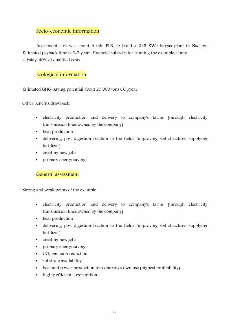
Investment cost was about 9 mln PLN, to build a 625 KWe biogas plant in Naclaw. Estimated payback time is 5-7 years. Financial subsides for running the example, if anysubsidy: 40% of qualified costs
Ecological information
Estimated GHG-saving potential about 20 000 tons CO2/year.
Other benefits/drawback:
• electricity production and delivery to company's farms (through electricity transmission lines owned by the company)
• heat production• delivering post-digestion fraction to the fields (improving soil structure, supplying
fertilizer)• creating new jobs• primary energy savings
General assessment
Strong and weak points of the example
• electricity production and delivery to company's farms (through electricity transmission lines owned by the company)
• heat production• delivering post-digestion fraction to the fields (improving soil structure, supplying
fertilizer)• creating new jobs• primary energy savings• CO2 emission reduction • substrate availability• heat and power production for company's own use (highest profitability)• highly efficient cogeneration
30

Technical problems met so far:
• administrative problems - Energy Company administration requires additional safety measures against power loss
• agreements with veterinary inspection • agreements with sanitary inspection • necessity of installing heat energy meters (to demonstrate high-performance
cogeneration)• frequent breaks in energy distribution by energy company ZE Koszalin due to
inefficient transmission infrastructure
Non-technical barriers:
• problem with utilisation of post-digestion product (area too small compared with the amount of post-digestion product obtained)
• requirement of having a back-up biogas boiler in case of a generator failure
31

9. FARM BIOGAS PLANT
PAWLOWKO, POLAND
Annotation
Paw ówko is a village located in north-western Poland, Pomorskie Voivodship, Powiatł Cz uchowski, Przechlewo Municipality. Poldanor, an animal and crop production company, builtł six agricultural biogas plants in the vicinity of farms managed by the company. The biogas plant in Paw ówko, opened in 2005 by Poldanor, was also the first facility of this kind to be built inł Poland.
General information
The biogas plant in Pawlowko was the first untertaking of this kind in Poland. It was opened on 9 June 2005. Poldanor operates in Poland since 1994. Its basic activity is animal and crop production.
The plant was set up to produce a better quality fertilizer from manure and to decrease the odours related to fertilizing fields with manure. The company is also realizing its environmental policy objectives, producing energy from a renewable source and reducing greenhouse gas emissions.
The farm biogas plant in Pawlowko was opened on 9 June 2005, two years after the administrational proceedings and construction work begun. In 2006, the plant produced 1478 MWh of electric energy, in 2007 - 2762 MWh, and now produces approximately 7 100 000 kWh of electric power annually.
Owing to the pro-ecological policy of the company, in 2005 the Management Board of Poldanor SA decided to build several agricultural biogas plants in the vicinity of farms managed by the company. In order to execute the idea and to carry out the necessary actions, the Biogas Department was established, with Benny Hedegaard Laursen appointed as its head and coordinator of its work. The team of highly qualified specialists in power production, building construction and biogas production are responsible for planning, design and supervision of the construction of the biogas production plant. The department also actively cooperates with the Institute for Renewable Energy as well as with research and development centres of universities in Poland and Denmark in the promotion and development of renewable energy sources.
32

www.poldanor.com.pl
The farm biogas plant in Pawlowko was established by Poldanor company. The basic activity of the company is breeding pigs, plant production and production of equipment of buildings for livestock. Breeding takes place in 17 own farms and 5 other farms cooperating under contracts with farmers. The area of the arable lands in use is more than 15,000 ha.The main input for the biogas plant is manure from farms in Pawlowko and Dobrzyn (approximately 29 000 t/year) and maize silage -7000 t/year. In this installation are also use waste from meat production (1000-1500 t/year). Manure, other agricultural products and waste are converted into odor-free, environmentally friendly fertilizers. In the process, electric and heat power are produced. Some of the power is used by the facility, surplus is sold. The income from energy sales comprises more than 3-5% of the overall income of the company.
Contacts
• Pawe Karwat or Anita Klimas, ł
tel. (+48) 59 833 43 [email protected]; [email protected]
• contact partner from our team: NAPEAnna Wiszniewska,tel. (+48) 22 505 45 69, [email protected]
Technical information
Agricultural biogas plants are biogas production facilities in which the technological process is based on mesophilic (37 ± 2°C) or thermophilic fermentation. The process of fermentation by methanogenic bacteria results in biogas containing 58-64% of biomethane and 36-42% of carbon dioxide. The energy raw materials used for biogas production include animal and plant production waste, maize silage, ground grain and glycerol. The biogas produced in the process is burned in a CHP module, which produces electricity and heat. The electric and heat is used partly by the facility itself, but the remaining part is sold to external consumers. The post-
33

production waste in biogas production is a fermented mixture of the energy raw materials, which can be used as a fertiliser or for compost production.
Main facilities of the biogas plant:
• Raw material reception station• Primary tank with pumping station• 2 digestion tanks• Technical facility with hygienisation unit• Post-digestion tank
Basic biogas plant specifications:
• Liquid manure input – 29 000 tons/year• Maize silage input – now 7 000 tons/year• Slaughter waste input – 1000 -1500 tons/year• Total capacity of digestion chambers – 1500m3
• 2 combined heating and power stations with the electric power of 526kWe and 420 kWe
Annual output if the biogas plant:
• Biogas approximately 3 000 000 m3
• Electric power approximately 7 100 000 kWh/year• Thermal energy approximately 7 600 000 kWh/year
34

Socio-economic information
Investment cost (construction and modernization) was 11 mln PLN, to build a 946 KWe biogas plant in Pawlowko. Expected payback time is 5-7 years.
Poldanor employs more than 490 people from Powiat Czluchowski. Poldanor's strategy is: “Contribution to development of local infrastructure, creation of workplaces for local society, and contribution to integration and economic and cultural cooperation between Poland and Denmark.” Among other things, Poldanor gives support through: co-financing of modernisation of local roads and other infrastructure in rural areas, sponsoring of sports clubs, cultural events, financing of needs of the disabled and sick, sponsoring of different initiatives related to environmental protection.
Ecological information
Estimated GHG-saving potential: about 20 000 tons CO2/year
Other benefits/drawback
• utilization of waste is paid for by the company that delivers waste • utilization of abattoir waste from a sister company• electricity production and delivery to company's farms (through electricity
transmission lines owned by the company)• heat production• reduction of odours from liquid manure • delivering post-digestion fraction to the fields (improving soil structure, supplying
fertilizer)• creating new jobs• primary energy savings• when substrate change is sudden, methane content changes, influencing the engine
operation (CHP), including engine stop when methane content is too low
General assessment
Strong and weak points of the example
• utilization of waste is paid for by the company that delivers waste • utilization of abattoir waste from a sister company• electricity production and delivery to company's farms (through electricity
35

transmission lines owned by the company)• heat production• reduction of odours from liquid manure • delivering post-digestion fraction to the fields (improving soil structure, supplying
fertilizer)• creating new jobs• CO2 emission reduction • primary energy savings• when substrate change is sudden, methane content changes, influencing the engine
operation (CHP), including engine stop when methane content is too low • substrate availability• heat and power production for company's own use (highest profitability)
Technical problems met so far
• administrative problems - Energy Company administration requires additional safety measures against power loss
• agreements with veterinary inspection • agreements with sanitary inspection • necessity of installing heat energy meters (to demonstrate high-performance
cogeneration)
Non-technical barriers
• lack of heat recipients • odours from the
hygienisation unit• problem with utilisation of
post-digestion product (area too small compared with the amount of post-digestion product obtained)
• requirement of having a back-up biogas boiler in case of a generator failure (Pawlowko does not have such a boiler) Digestion tank building.
36

Inside of the digestion tank building.
Photos: Poldanor
37

10. ENERGY INDIPENDENT FARM
VENARIA, (TO), ITALY
Annotation
The aim of “La Bellotta” is to become an energy independent farm. This objective is carried out through production of Biogas from biomass sources and co-generation. Also the future use of tractors with fuel cells (from CNH), that run with hydrogen from biomethane generation, will make the farm unique in term of self sufficiency from fossil fuel sources
General information
Given the national incentives (0,28 €/kWh) to the production of electric energy from biomass local sources, the farm “La Bellotta s.s.” decided to implement an anaerobic digestion system and biogas production. In June 2009, the company filed for permission for the construction and activity of the plant at the Province of Turin. The “Conferenza dei servizi” (typical meeting of Italian legislation) was held in September 2009 and the Province of Turin, after gaining the favorable opinions of the other public bodies involved in the process, has granted permission in December 2009.
The company is keen to put their crops in an anaerobic digestion plant and biogas to produce electricity to be sold to the national grid. The company has also decided to invest in that sector to cope
38

the recent economic difficulty conditions which was caused by fell sharply of sales prices of commodities after peaking in 2007.
The result of the digestion process is then spread on the same fields which the biomass crop comes from, aiding the environment with the save of mineral fertilizers, whose production results in substantial energy consumption.
The aim of the farm is to become the first energy indipenden farm in Italy. A NH2™ hydrogen-powered prototype will become operational at the farm by the third quarter 2011.
Hydrogen will be experimentally generated using electricity from photovoltaic panels and via the steam methane reforming of a new 1MW biogas plant inaugurated on the farm in early August 2010.
The practical trial will begin at La Bellotta Farm in Venaria, a few kilometres outside of Turin. By the end of 2011 the farm will see the introduction of the first of New Holland’s second-generation NH2™ tractors, which will be used to trial electrical-powered implements such as seed drills, planters, transplanters and spreaders.
The NH2™ hydrogen-powered tractor uses fuel cell technology to generate electricity that powers its electric drive motor; on-board auxiliary apparatus and even electrical tilling implements. Based on the New Holland T6000 tractor, the model in operation at La Bellotta will have three fuel cells with a total power output of 100 kW.
Technical information
The biogas plant consist of the following structures:
• 3 trenches for the storage of plant biomass input• 2 pre-tank for the loading of liquid matrix into digestion system• 2 digesters where anaerobic digestion happens• Technical control structure and container for co-generator and transformer: the gas
collected into gasometrical dome is sent to a cogeneration system made by a four-stroke engine, coupled with synchronous alternator, with a nominal power approximately 2.458 kW. The engine has an electrical efficiency of 40,6% that releases a power of 989 kWe. The thermal energy is generated at full load through the heat exchanger of the cooling engine for a power of 573 kWt and an efficiency of 23%.
39

• Storage facilities for outgoing materials: tank for the final storage of the digested liquid fraction and shallow manure pit for solid fractions.
The plant is daily fed with a mixture of approximately 47.5 t of biomass (including 38.5 t of corn silage, 4 t of triticale silage and 5 t of sorghum silage ), plus about 10 t / day of recirculated from the liquid fraction of digestate.
In the digestion plant will be demolished almost the entire volatile portion (90 - 95%) of dry matter input: it follows a daily production of approximately 11.600 Nm3 gas and a output of digested mass of the plant about 43,2 t/day, that is sent to mechanical separation, after which the remaining liquid fraction is partly recycled in the digesters (10 t/day), partly released into the final storage tank (27.7 t/day), while the solid fraction (5.5 t/day) is discharged and the shallow manure pit.
Daily production of biogas is about 11.600 Nm3 gas, with an average content of methane in the biogas produced of 53%. The cogeneration group work for approximately 8.500 maxim hours per year, while the remaining hours are used for maintenance, which involves an annual production of electricity amounted to 8,483,000 kWhe. About 5% of the energy produced is used for the operation of the auxiliary services, for which the share sold to the national grid amounted to 8.050.850 kWhe.
The thermal energy is generated at full load through a heat exchanger cooling water engine, to a power equal to 537 kWt and an exchanger and flue gases - water for a power equal to 428 kWt: some of this energy (with estimated peak about 560 kWt) is reused in the plant to heat the digesters, while the remainder is used to heat 14 <inserire il riscaldamento del centro aziendale > apartments, located approximately 250 m south - west of the plant.
The innovative solution to remove suphur from the gas allows long lifetime for the engines and less/null emissions of SO2 after gas combustion. In addition, the use of a special unit with Lithium Bromure to cool down and remove moisture from the gas allows other important saving in the energy required by the plant.
40

Socio-economic information
INVESTMENTSUMMARY N €/CAD €Proposed plantBiogas plant 1.739.000Cogeneration engine 1 900.000 960.000SCR plant 0 150.000 -weighing machine, varius 0 18.576Works in concrete (digesters, tanks, trenches) 926.000Accessory works 0 25 59.000Completion of earthworks and ancillary works 105.480TOTAL WORKS 3.808.056Technical and general expenses 5% 171.363TOTAL 3.979.419GRAND TOTAL 3.979.419Government grant 0%ACTUAL INVESTMENT 3.979.419
The approach adopted for the system provides synergy among many local companies, which related by contracts for the delivery of the product (silage), and, most importantly, the agronomic use of the digestate, which will allow substantial savings for chemical fertilizers. The creation of these agreements enable the supply chain to reach out to the small producer with a significant economic impact in terms of product prices, which the plant will be able to recognize in return for fidelization of delivery and a good quality standard guaranteed for the biomass.
Important will also be part of the delivery of skilled labor from the farm to the plant, aiming to perform important tasks such as collection and storage of silage, the loading system and the spreading of the digestate with its rapid burial. These effects will be extremely important for local businesses and work.
After a detailed analysis of emissions during pre-and post-implant was possible to arrive at an evaluation summary. Below are tables of the situation before and after installation and phase specific analysis:
41

Comparison between the emission situation before and after plant construction.
(a minus sign indicate savings)
PARAMETER CO2 CH4 NOx NH3 CO PMUNITS t/y t/y t/y t/y t/y t/yBefore plant 4.111,42 7,09 8,15 2,22 3,77 1,51After plant 273,36 4,07 14,90 8,46 15,63 0,32Delta - 3.838,06 - 3,02 6,75 6,25 11,86 - 1,18
In addition to the sale of electricity to the network, the company also values the share of thermal energy of cogeneration, which is sold by the district heating network of 14 housing units located in the area close to the plant and the large farm area, avoiding the use of fossil fuels for the operation of traditional boilers. The ability in the fully exploitation of share of electricity and heat co-produced makes these types of systems even more virtuous from the standpoint of environment.
The digested output of the installation is an excellent resource fertilizer (input) and soil amendment, which is enhanced by spreading on fields from which comes the biomass entering the plant: this use allows to close a kind of biological cycle and saves a lot of mineral fertilizers, whose production results in a substantial energy consumption. To allow large energy saving and to use the digestate in a timely manner, the farm just built a 7 km umbilical system, used for both irrigation and digestate distribution.
In the future the farm objective is to be energy independent with the use of New Holland Tractor T6000, with fuel cells, that run with hydrogen from biomethane generation, will make the farm unique in term of self sufficiency from fossil fuel sources. Hydrogen will be produced following the process presented in the picture
Stab ilized sewage
Biomass input
Mechanical pretreatment and biomass homogenization
Bioreactor for H 2production Bioreactor for biogas
production
Exhausted gas
Biogas purif icationH2 purif ication
H2 storage Biogas storage
Digested sludgeGas recirculated
Nutrient reintegration
Continuous process
Dark anaerobic fermentation process
42

General assessment
The agricultural enterprise “La Bellotta s.s.”, though the use of biomass from dedicated cultivations for energy purposes, has been able to support the development of a dedicated plant to produce electrical and thermal energy. Through it is possible to derive energy from a renewable source of energy and not from a fossil fuel reserves, derived from exhaustible (oil): in fact, the CO2
released in combustion of the biogas is absorbed by plant organisms (plants corn or other energy crops), which are in turn used to produce biomass treatment in the plant of anaerobic digestion.
The use of the gas to make purified hydrogen for tractors with zeroemission will make the farm virtually energy indipendent and with zero emission from fossil fuels to run the equipment for agricultural operations.
Thus the biogas plants now represent an effective alternative to energy production from fossil fuels and allow the adoption of a rewarding sustainable policy in the environmental aspect.
43

11.
SECOND GENERATION BIOETHANOL DEMONSTRATION PLANT CRESCENTINO (VC), ITALY
Annotation
Is a Innovative and sustainable biotechnological conversion of lignocellulosic biomass into bioethanol in a 51 million liters per year plant. The integrated biofuel demo plant will be capable of converting lignocellulosic biomass from selected energy crops into bioethanol utilizing proprietary process and component design, novel enzymes cocktail and high efficiency fermenting microorganisms.
General information
The Crescentino Bioethanol Plant will be managed by the society Italian Bio Products (IBP – M&G) with the support of Chemtex Italia, a wholly-owned global engineering subsidiary of Mossi & Ghisolfi (M&G). The Bioethanol Plant will be built in the Town of Crescentino (VC), that is located in Piemont region, North West of Italy (40 km from Turin, 115 km from Milan, 140 km from Genoa).
Since 2006, Chemtex-M&G has conducted research into cellulosic crop optimisation and agronomics, has designed, engineered, developed and test at lab and pilot scale proprietary technology and components for key aspects of the biomass to fuel conversion process and has partnered with leading technology providers for the key biological process components. Building a bioethanol facility to demonstrate this technology in Europe is the next incremental step in development of the M&G/Chemtex technology. Information needed for the successful scale-up to commercial scale, necessitates the construction and operation of this demonstration plant in Europe.
The Second generation 40.000 ton/y BioEthanol Plant has established the following overall project goals:
• Demonstration at commercial scale of a new pretreatment technology (unique process producing high quality low cost sugars from lignocellulosic biomass, running on a continuous pilot scale in Chemtex R&D Center since June 2009)
44

• High efficiency in viscosity reduction and enzymatic hydrolysis with unique patented process design
• Incorporation of innovative Hydrolysis and fermentation steps (simultaneous co-fermentation of C5 and C6 sugars in a SSF set up)
• Incorporate all component designs into an integrated and techno-economic sustainable process package
• Prove the economic viability of the process design• Ensure that environmental, safety, health and security requirements are fully
incorporated and properly implemented into the project’s design and execution.
The permitting phase of he Crescentino Ethanol Plant has been started from March 2010.
Timeframe:
Basic engineering start March 2010Permitting phase completed Q1 2011 Ground breaking April 12, 2011Construction start May 2011Mechanical completion April 2012 Plant start-up Q2 2012
Mossi & Ghisolfi (M&G) is a multinational group – headquartered in Tortona (AL, Italy) with global operations in US, Italy, Brazil, India, China and Mexico – that is the world leader in polyethylene terephthalate (PET plastics) in both production quantity and technology. M&G has a proud heritage of successfully delivering on technically challenging projects around the world. It is this experience that shapes the future for M&G in the renewable and alternative energy sectors and strengthens the development technology for the conversion of renewable biomass into liquid transportation fuel at a cost competitive with petroleum.
Firms of the MOSSI & GHISOLFI Group involved in the Second generation bioethanol plant:
• M&G FINANZIARIA Srl (M&G) –www.gruppomg.comLegal office: Strada Ribrocca n. 11 15057 Tortona (AL), Italy
• Italian Bio Products SpA (IBP) www.biocrescentino.itLegal office: Strada Ribrocca n. 11 15057 Tortona (AL), Italy – Owner of the Crescentino Bioethanol plant
45
• Chemtex Italia Srl (Chemtex) www.chemtex.comLegal office: Strada Ribrocca n. 11 15057 Tortona (AL), Italy
Bio-fuels production from the fermentation of simple sugars derived from non-food related and geographically suitable biomasses that can substitute for commercial grade fossil fuels (gasoline, diesel) area is an achievable target. Bioethanol is the most produced biofuel worldwide with almost 74 billion litres in 2009. Recently, multiple large oil companies have approached M&G, expressing interest in the technology and requesting data needed to support capital projects.
Contacts
• Giuliano GHIGLIONE – VP for Business Development CHEMTEX ITALIAPhone +39 0131-810369 E-mail [email protected] Strada Ribrocca, 11 – 15057 Tortona (AL) – ITALY
• Alessandra FRATTINI – R&D Funding Projects Manager CHEMTEX ITALIAPhone +39 0131 882839 E-mail: [email protected] Strada Savonesa, 9 – Blocco D – 15057 Tortona (AL), Frazione Rivalta Scrivia – ITALY
Based on Chemtex’s biofuels engineering experience, M&G has conducted a complimentary research in the bioethanol area for over five years. With these R&D activities, M&G Group has demonstrated the feasibility of the process by completing a 120 million euro research programme on second generation ethanol technology from lignocellulosic biomass (PROESATM – Bio-ethanol production from lignocellulosic biomass).
Since 2008, R&D activities of the PROESATM technology have received the support of several collaborative national and international projects, such as:
• Agronomic research in cooperation with Italian Region (Piedmont and Emilia Romagna) and Mexico
• Basic research with Piedmont Region• Research at pilot scale with Piedmont Region and FP7- NEMO Project• Development of Pretreatment process with Industria 2015 – PRIT Project
46

• Development of Hydrolysis and Fermentation steps with FP7 – Biolyfe Project
Technical information
The plant is designed to produce bioethanol through hydrolysis and fermentation of cellulose and hemicellulose starting from lignocellulosic biomass (Arundo Donax or Wheat Straw). The denaturant will be added to the produced alcohol before mixing with gasoline.
The main process steps for ethanol production from lignocellulosic feedstock are:
• Biomass pretreatment to destruct the lignocellulose matrix and solubilize C5 and C6 sugars;
• Hydrolysis to reduce the cellulose and hemicellulose into fermentable sugars;• Fermentation of sugars to ethanol;• Solid separation, ethanol recovery and dehydration.
The technology development target is to design an energy efficient pretreatment process able to produce pretreated material that facilitates optimal enzymatic and microorganism activity. In particular many efforts have been done to limiting formation of degradation products that could inhibit enzyme and microorganism performance.
Plant is designed to guarantee flexible operation with different feedstock and to maximize ethanol yield. Liquid effluent coming from the process section are sent to waste water treatment where organic content is converted to biogas. Biogas is used for steam production. Redundant systems are integrated in critical sections of the plant to guarantee the maximum reliability in all the expected run conditions, during start up and shout down operations.
The Second generation BioEthanol Plant Production main figures
PRODUCTION Unit [unit/year]BIOETHANOL [liter] 50,697,085Lignin cake [Ton] 164,019Biogas [Ton] 11,18
Socio-economic information
The overall investment costs at Crescentino site including site acquisition and
47

refurbishing, power generation unit, waste water treatment and ethanol production plant is more than 100 mln/€.
It is expected that more than 100 people, including partners, employees and highly specialized consultants, will work all together by this plant. The manpower will be mainly local. The Company indicated that, in agreement with the Farmers' Associations, it will define a framework agreement to be signed by the individual farmers who will express their willingness to grow Arundo donax.
LCA results. On a life cycle basis, without taking into consideration energy credits from co-products, total non-renewable energy use is 1.13 MJ/km for the bioethanol case and 2.55 MJ/km for the gasoline case. The relevant energy credit arising from surplus co-produced electricity allows to reduce the global non-renewable energy use for the bioethanol life cycle to 0.91 MJ/km: this means a 64% reduction with respect to the conventional gasoline pathway. For each kg of bioethanol produced, gross GHG emissions are 1.174 kgCO2 equivalent while an emission credit of 0.462 kg CO2 equivalent is related to the surplus electricity produced, resulting in a net GHG emission of 0.712 kgCO2 equivalent per kg of ethanol. The comparison with gasoline over the whole life cycle shows a significant reduction of GHG emissions for second generation bioethanol: 51 gCO2 equivalent /km with respect to 172 gCO2 equivalent /km of the gasoline pathway, equivalent to a 70% GHG emission saving.
The Crescentino plant is designed to utilize Arundo Donax or Wheat Straw as main feedstocks.
The production capacity of the plant is 51 million liters (40,000 T) of bioethanol per year, with a dry biomass input of about 160,000 – 180,000 T/y. Within a radius of 70 km from the plant are available 9,388 ha of uncultivated land, so the estimated land needed for plantation is about 5,200 ha distributed in an area.
A short supply chain resulting from an ethanol facility surrounded by the fields producing the feedstock and providing it to the plant is assumed. A model of Material Requirement Planning is being studied by a research project Goarundo (with includes, among the partner, DEIAFA-University of Turin) with the aim to deliver the biomass on demand without large storage and needs of drying process that could lower the energy balance of the process. A long term supply agreement with Italian companies (direct farmers, Coop, Agricultural consortium, Agricultural Federations) specialized in agricultural products is under negotiation to secure the feedstock to the plant . Wheat straw, as alternative biomass, is available on the commodity market and from the farmers around the plant.
48

General assessment
The Crescentino Plant Key Features
• Production based on Arundo donax (only 4,000 Ha of the lower quality land to be converted to this energy crop cultivation) and wheat straw
• Demonstration at commercial scale of a new pretreatment technology • High efficiency in viscosity reduction and enzymatic hydrolysis with unique patented
process design • Incorporation of innovative fermentation step• Dry Ethanol sell to major oil company/ies • 68.000 ton of CO2 emission saved per year• Production of 51 Ml/y (40.000 t/y) of Ethanol • Production of the co-product Lignin free from sulfur, clorine and ammonia that can
constitute an unique base for producing chemical from biomass in addition to energy • Low OPEX: possibility to produce cost competitive bioethanol in almost any
geographical area (conversion of renewable biomass into liquid transportation fuel at a competitive cost with petroleum)
Non-technical barriers
The construction permit was held on April 2011 and the plants was modified in order to respond to local, Italian and European laws.
49