Subsurface Flow Controls - · PDF fileSubsurface Flow Controls Locks and Landing Nipples ......
30
© 2016 Halliburton. All rights reserved. Subsurface Flow Controls
Transcript of Subsurface Flow Controls - · PDF fileSubsurface Flow Controls Locks and Landing Nipples ......

© 2016 Halliburton. All rights reserved.
Subsurface Flow Controls
2 © 2016 Halliburton. All rights reserved.
Subsurface Flow Controls
Locks and Landing Nipples – X®, R®, RPT, SRH Nippleless Plugs - Mirage® and Evo-Trieve bridge plugs
DuraSleeve® Sliding Side-Door® circulating device
Wellhead Plugs - SRP, SSP
Accessory Items – flow couplings, blast joints

© 2016 Halliburton. All rights reserved.
Locks and Landing Nipples
4 © 2016 Halliburton. All rights reserved.
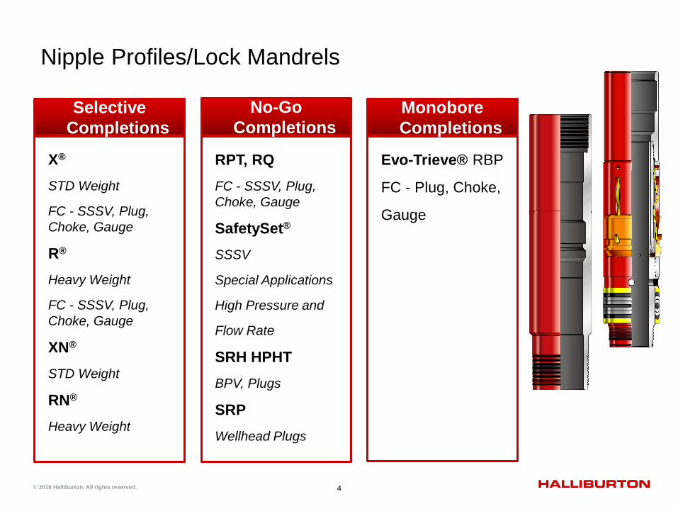
Nipple Profiles/Lock Mandrels
X®
STD Weight
FC - SSSV, Plug, Choke, Gauge
R®
Heavy Weight
FC - SSSV, Plug, Choke, Gauge
XN®
STD Weight
RN®
Heavy Weight
Selective Completions
RPT, RQ FC - SSSV, Plug, Choke, Gauge
SafetySet® SSSV
Special Applications
High Pressure and
Flow Rate
SRH HPHT BPV, Plugs
SRP Wellhead Plugs
No-Go Completions
Evo-Trieve® RBP
FC - Plug, Choke,
Gauge
Monobore Completions

5 © 2016 Halliburton. All rights reserved.
X® & R® Selective Landing Nipple/Locking Mandrel System
OTIS X® Landing Nipple
OTIS® X® Locking Mandrel
Design Benefits ▌ Nipples installed in tubing string in any order- reducing
workover risk ▌ Provides unlimited number of positions to set ▌ Running tool allows selection of nipple to land and set
the lock ▌ Same ID in all nipples reducing flowing pressure loss and
minimizing turbulence ▌ Maximum flow capacity from large, straight-through bore
of locking mandrel ▌ Maximum versatility reducing completion and production
maintenance costs ▌ Allows for repositioning of flow controls as well conditions
change ▌ Keys of locking mandrel retracted into assembly while
running and retrieving
6 © 2016 Halliburton. All rights reserved.
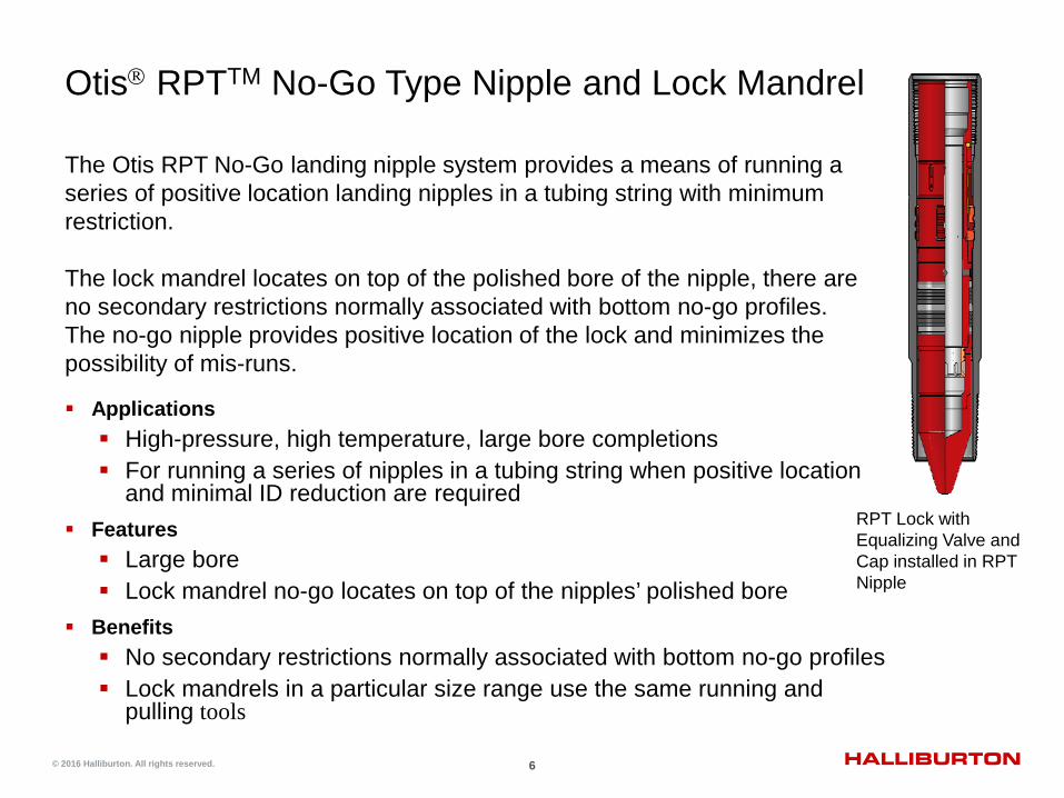
Otis RPTTM No-Go Type Nipple and Lock Mandrel
Applications High-pressure, high temperature, large bore completions For running a series of nipples in a tubing string when positive location
and minimal ID reduction are required Features Large bore Lock mandrel no-go locates on top of the nipples’ polished bore
Benefits No secondary restrictions normally associated with bottom no-go profiles Lock mandrels in a particular size range use the same running and
pulling tools
The Otis RPT No-Go landing nipple system provides a means of running a series of positive location landing nipples in a tubing string with minimum restriction. The lock mandrel locates on top of the polished bore of the nipple, there are no secondary restrictions normally associated with bottom no-go profiles. The no-go nipple provides positive location of the lock and minimizes the possibility of mis-runs.
RPT Lock with Equalizing Valve and Cap installed in RPT Nipple

7 © 2016 Halliburton. All rights reserved.
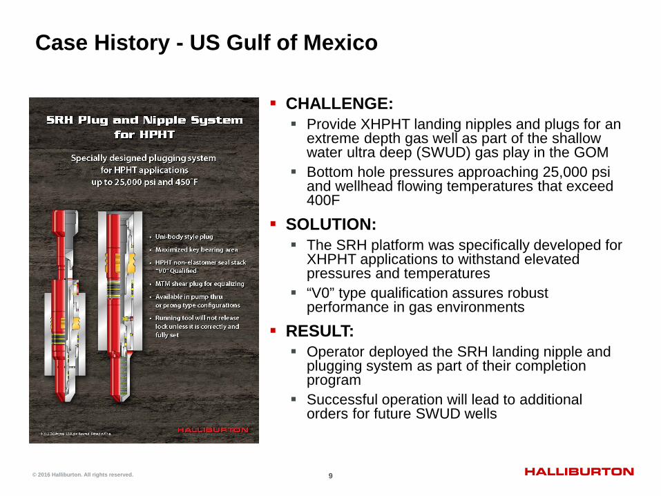
SRH Plug and Nipple System for HP/HT
Uni-body style plug
3 x 45 deg loading surfaces on key above and below, maximizing key bearing area
HP/HT non-elastomer seal stack “V0” Qualified to 25,000 psi and 450F
MTM shear plug for equalizing

8 © 2016 Halliburton. All rights reserved.
SRH Plug Operational Benefits
Two plug types possible Pump through capable plug
»Prong installed for a positive plug to hold pressure from above
Conventional prong type plug (as shown)
Two moving parts, expander sleeve and keys
Running tool does not release unless lock is correctly and fully set
9 © 2016 Halliburton. All rights reserved.
Case History - US Gulf of Mexico
CHALLENGE: Provide XHPHT landing nipples and plugs for an
extreme depth gas well as part of the shallow water ultra deep (SWUD) gas play in the GOM
Bottom hole pressures approaching 25,000 psi and wellhead flowing temperatures that exceed 400F
SOLUTION: The SRH platform was specifically developed for
XHPHT applications to withstand elevated pressures and temperatures
“V0” type qualification assures robust performance in gas environments
RESULT: Operator deployed the SRH landing nipple and
plugging system as part of their completion program
Successful operation will lead to additional orders for future SWUD wells

© 2016 Halliburton. All rights reserved.
Nippleless Plugs

11 © 2016 Halliburton. All rights reserved.
Fully qualified to ISO 14310 V0 qualification
Max pressure rating of 7,500 psi (above / below)
Temperature 40°F to 325°F
Plug design is as compact as possible
Top sub equalize and release (GS profile)
Evo- Trieve™ Bridge Plug Development Objectives

12 © 2016 Halliburton. All rights reserved.
Overview - Evo-Trieve™ Bridge Plug
Equalizing Sub Slip System Packing
Element Guide Sub

FOR INTERNAL USE ONLY.
1. Autofill and Mirage plug are run to depth below a hydraulic set packer. The tubing is filled through the Autofill when running downhole.
2. Multiple pressure cycles against the Mirage plug allows closure of Autofill, tubing test and setting of packer.
3. Final pressure cycle dissolves Mirage plug matrix for full bore access.
Production Packer Autofill Device + Mirage Plug
Mirage® Disappearing Plug and Autofill Device

FOR INTERNAL USE ONLY.
Allows for 6 - 7 tubing pressure cycles of 4000 psi (minimum cycle pressure) Note: hydrostatic overbalance from
tubing to annulus must be <600 psi
On final pressure cycle, the fresh water is introduced into the plug and expends
Applications In: Horizontal wells Setting production or isolation
packers Testing tubing Wells where slickline or CTU
intervention after completion is undesirable
Rubber membrane
Self contained fresh water in ID of tool
Expendable plug
Cycle mechanism
Multi-Cycle Mirage® Disappearing Plug (MPB)
15 © 2016 Halliburton. All rights reserved.
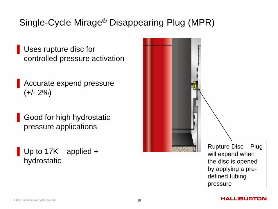
Rupture Disc – Plug will expend when the disc is opened by applying a pre-defined tubing pressure
▌Uses rupture disc for controlled pressure activation
▌Accurate expend pressure (+/- 2%)
▌Good for high hydrostatic pressure applications
▌Up to 17K – applied + hydrostatic
Single-Cycle Mirage® Disappearing Plug (MPR)

16 © 2016 Halliburton. All rights reserved.
Case History – Mirage Plug replaces POP in Malaysia
CHALLENGE: Design a simple and effective open hole
completion for an 18 well campaign for a major operator in Malaysia
The original completion design included a pump out plug (POP) for tubing testing and packer setting
SOLUTION: Replace the POP with the Mirage
disappearing plug and Autofill sub Eliminates the need to pump down a ball to
expend the POP, which can be problematic and time consuming in horizontal or highly deviated wells
RESULT: The operator chose the simplicity and time
savings of the Mirage plug for the campaign Mirage plug has become the standard for all
the customers horizontal openhole wells
© 2016 Halliburton. All rights reserved.
Sliding Side-Door®
Circulating Devices

FOR INTERNAL USE ONLY.
18 DuraSleeve® Non-Elastomer Circulation / Production
Sleeve
Applications in: Producing alternate zone in single-selective
completions Circulating kill fluid eliminates expense of
perforating tubing Secondary recovery Washing above packer Design Capability: Sizes 1 ½-in. to 7 in. Pressure rating equal to tubing rating Open-up and open-down options using B
shifter

19 © 2016 Halliburton. All rights reserved.
Shifting forces for Nitrile Seal, PEEK seal, and the DURATEF™ ECM seal
Designing sleeves to shift after years of production
Shifting forces for DuraSleeve® sliding sleeve are less than 1/5 the force required for sleeves with competitive
materials such as PEEK
Shifting Force of DURATEF™ ECM Seals

20 © 2016 Halliburton. All rights reserved.
Slimline Sliding Side-Door® Device
Small OD SSD designed for concentric string gravel pack completions Allows for running larger size tubing inside
small ID casing 2 3/8-in. – 2.72 v. 3.25 OD 2 7/8-in. – 3.22 v. 3.92 OD 3 ½-in. - 3.92 v. 4.50 OD OD’s comparable to CS Hydril upset 5000 psi rating (more with material upgrade) Tensile rating 60-70% of N-80 tubing Standard B shifting tool

© 2016 Halliburton. All rights reserved.
Wellhead Plugs

22 © 2016 Halliburton. All rights reserved.
SRP Wellhead Plugs
Deepwater development has created demand for wellhead plugs
Used primarily in subsea trees
Ultra-compact design allows for use in horizontal trees
Available in equalizing and non-equalizing models
High-pressure rating above and below
No-go design with minimum restriction

23 © 2016 Halliburton. All rights reserved.
SRP Wellhead Plug
Design Features
Compact length reduces space requirements of wellhead
Single leak path is through two full packing stacks
High pressure rating from above and below
Multiple shear pin hold down mechanisms for redundancy
Simple design for high reliability. Only two moving parts: keys and expander sleeve
24 © 2016 Halliburton. All rights reserved.
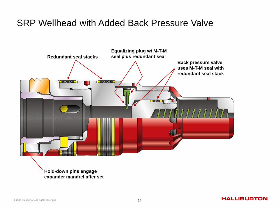
SRP Wellhead with Added Back Pressure Valve
Redundant seal stacks Back pressure valve uses M-T-M seal with redundant seal stack
Equalizing plug w/ M-T-M seal plus redundant seal
Hold-down pins engage expander mandrel after set

25 © 2016 Halliburton. All rights reserved.
SRP Wellhead Back Pressure Valve
Optional test prong isolates the back pressure valve to allow pressure testing of SRP plug from above

26 © 2016 Halliburton. All rights reserved.
SSP Wellhead Plug
MTM seal plus a single packing stack, compatible with FMC wellhead
Compact length
Test pressures up to 15,000 psi
API 17D, API 14L, PR-2 and vibration tested
Static after set
Hydrostatic running tool applies predetermined force into expander sleeve taper
3 degree taper statically sets key into profile for no plug movement
Secondary interference locking sleeve
Three fishnecks
Two fishnecks on expander sleeve
Additional fishneck on plug body
Interference Sleeve for Secondary Hold Down
MTM Seal
3° Taper
Second Fishneck
Third Fishneck
First Fishneck
Expander Sleeve
Debris Barriers

© 2016 Halliburton. All rights reserved.
Accessory Items
28 © 2016 Halliburton. All rights reserved.
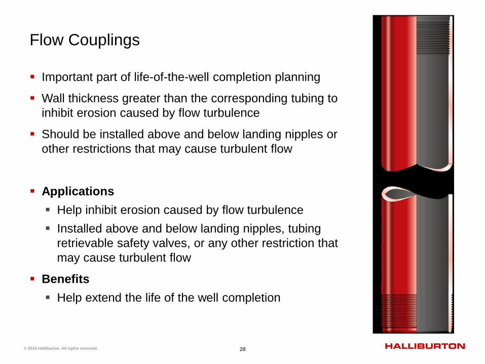
Flow Couplings
Important part of life-of-the-well completion planning
Wall thickness greater than the corresponding tubing to inhibit erosion caused by flow turbulence
Should be installed above and below landing nipples or other restrictions that may cause turbulent flow
Applications Help inhibit erosion caused by flow turbulence Installed above and below landing nipples, tubing
retrievable safety valves, or any other restriction that may cause turbulent flow
Benefits Help extend the life of the well completion
29 © 2016 Halliburton. All rights reserved.
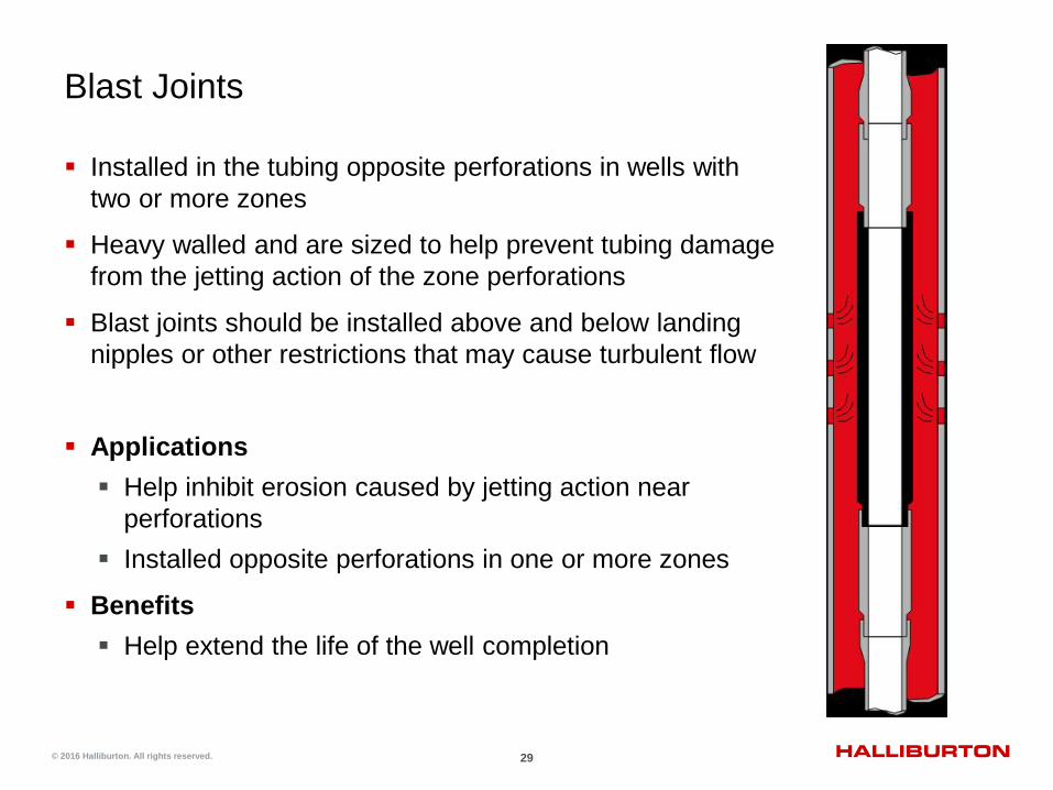
Blast Joints
Installed in the tubing opposite perforations in wells with two or more zones
Heavy walled and are sized to help prevent tubing damage from the jetting action of the zone perforations
Blast joints should be installed above and below landing nipples or other restrictions that may cause turbulent flow
Applications Help inhibit erosion caused by jetting action near
perforations Installed opposite perforations in one or more zones
Benefits Help extend the life of the well completion

30 © 2016 Halliburton. All rights reserved.