Submittal of the Responses to Source Term …1 Draft Audit Questions-Response Status Post-Audit Exit...
15
1 Draft Audit Questions-Response Status Post-Audit Exit Meeting on August 20, 2015- APR1400 Chapter 12 Radiation Protection--Source Term Calculations Audit Background The purpose of this document is to document resolution/action items developed among NRC staff and KHNP and KEPCO E&C from the audit exit meeting on August 20, 2015. Plans are for KHNP/KEPCO E&C to respond back to NRC by 08/28/2015. The following is a legend of the proposed resolutions: RAI: The staff will issue an RAI on the topic. DCD markup: The applicant may provide a DCD markup to address the NRC staff’s concern on the topic. Audit observations – Open items: The applicant is to discuss internally and then let staff know their proposed approach going forward. Audit observations – Closed Items: No further action from the applicant is needed. These results will be documented in the audit report, as stated in the audit plan (see ML15208A492). The audit team will issue an audit summary within 45 days that will be declared and entered as an official agency record in the NRC’s Agencywide Documents Access and Management System (ADAMS) records management system. Draft -Audit Questions 1. The applicant indicates that they are excluding the removal of Yttrium from the CVCS, SI system, and safe shutdown cooling system. In the response to RAI 7896, Question 12.02-4, the applicant indicates that this was assumed for the CVCS for simplification and because WASH-1258, does not include a removal fraction for Yttrium for cation removal. However, WASH-1258 is dated 1973 and is not referenced in the Chapter 11 or 12 SRP or Regulatory Guide 1.206. Furthermore, more recent guidance documents which are referenced in the SRP provide removal rates which would include Yttrium. Specifically, both NUREG-0017 and ANSI-18.1-1999 indicate that mixed bed purification ion exchangers would have an efficiency of 98% for Yttrium. In addition, even though the applicant does not consider removal of Yttrium for the CVCS, SI system, and safe shutdown cooling system, the 0.25% and 1% failed fuel RCS source terms do consider Yttrium removal by the CVCS. In addition, it does not appear that expected effluent release rates have been modified to consider no Yttrium removal. Not accounting for Yttrium removal by the CVCS also effects other source terms, such as the solid waste management system, as some of these sources are derived from the CVCS. Please correct all source terms to account for Yttrium removal in the appropriate systems in amounts anticipated for the equipment being used, or provide additional justification for why the current approach is acceptable. RAI: The staff will issue an RAI on the topic.
Transcript of Submittal of the Responses to Source Term …1 Draft Audit Questions-Response Status Post-Audit Exit...

1
Draft Audit Questions-Response Status Post-Audit Exit Meeting on August 20, 2015- APR1400 Chapter 12 Radiation Protection--Source Term Calculations Audit Background The purpose of this document is to document resolution/action items developed among NRC staff and KHNP and KEPCO E&C from the audit exit meeting on August 20, 2015. Plans are for KHNP/KEPCO E&C to respond back to NRC by 08/28/2015. The following is a legend of the proposed resolutions:
RAI: The staff will issue an RAI on the topic. DCD markup: The applicant may provide a DCD markup to address the NRC staff’s
concern on the topic. Audit observations – Open items: The applicant is to discuss internally and then let staff
know their proposed approach going forward. Audit observations – Closed Items: No further action from the applicant is needed.
These results will be documented in the audit report, as stated in the audit plan (see ML15208A492). The audit team will issue an audit summary within 45 days that will be declared and entered as an official agency record in the NRC’s Agencywide Documents Access and Management System (ADAMS) records management system. Draft -Audit Questions
1. The applicant indicates that they are excluding the removal of Yttrium from the CVCS, SI
system, and safe shutdown cooling system. In the response to RAI 7896, Question 12.02-4, the applicant indicates that this was assumed for the CVCS for simplification and because WASH-1258, does not include a removal fraction for Yttrium for cation removal. However, WASH-1258 is dated 1973 and is not referenced in the Chapter 11 or 12 SRP or Regulatory Guide 1.206. Furthermore, more recent guidance documents which are referenced in the SRP provide removal rates which would include Yttrium. Specifically, both NUREG-0017 and ANSI-18.1-1999 indicate that mixed bed purification ion exchangers would have an efficiency of 98% for Yttrium. In addition, even though the applicant does not consider removal of Yttrium for the CVCS, SI system, and safe shutdown cooling system, the 0.25% and 1% failed fuel RCS source terms do consider Yttrium removal by the CVCS. In addition, it does not appear that expected effluent release rates have been modified to consider no Yttrium removal. Not accounting for Yttrium removal by the CVCS also effects other source terms, such as the solid waste management system, as some of these sources are derived from the CVCS. Please correct all source terms to account for Yttrium removal in the appropriate systems in amounts anticipated for the equipment being used, or provide additional justification for why the current approach is acceptable.
RAI: The staff will issue an RAI on the topic.
2
Audit observation-Open Item: The applicant is to discuss internally and respond by 8/28/2014 with proposed resolution/response or at least a statement of that the question is understood.
DCD markup: The applicant may provide a DCD markup to address the NRC staff’s concern on the topic.
Response: KHNP will calculate the source terms for purification ion exchanger by using the DF=50 (efficiency of 98%) instead of DF=1 (efficiency of 0%) for Yttrium and evaluate the impact on other source terms, such as the solid waste management system. The result will be provided as a part of RAI-8339 response.
2. The gaseous radwaste system (GRS) source terms are based, in part, on 0.32 scfm
continuous venting of the gas stripper to the gaseous radwaste system. Please discuss the basis for this value (is it the maximum rate).
Audit Observation-Open Item: The applicant is to check the noted calculation parameters and provide information on the basis of vapor volume and related calculations.
Response: The gas stripper removes dissolved radioactive noble gases from continuous letdown flow, from refueling and shutdown wastes and from leakage. Total refueling wastes and the venting flowrate of gas stripper are calculated as follows: Cycle length (day) : 480 Letdown flowrate (gpm) : 80 1) Liquid volume from letdown during one cycle (gal) : 55,296,000
(=80 gpm * 480 day * 24 hr/day * 60 min/hr) 2) Total refueling waste (gal) : 211,700
- Waste of refueling shutdown (gal) : 46,800 - Waste of drainage (gal) : 42,700 - Waste of refueling startup (gal) : 122,200
3) Cold shutdown and Startup during normal operation (gal) : 100,252 4) Leakage from RDT and EDT (gal) : 144,000
- RDT (gal) : 120,000 (=250 gpd * 480 day) - EDT (gal) : 24,000 (=50 gpd * 480 day)
Total liquid volume of normal waste = 55,751,952 gal * 3.785 kgH2O@STP/gal
= 2.11E+08 kgH2O@STP
The water density is assumed to be 1 g/cm3. Gas stripper will be assumed to be 100% efficient and remove 30 cm3/kgH2O of gas. Gaseous volume stripped by the gas stripper during one cycle
= 2.11E+08 kgH2O * 30 cm3/kgH2O = 6.33E+09 cm3

3
Cycle average vent flow rate = 6.33E+09 cm3 *3.531E-5 ft3/cm3 / (480 day * 1440 min/day) = 0.32 scfm
DCD markup: The applicant may provide a DCD markup to address the NRC staff’s
concern on the topic. Audit Observation-Open Item: KHNP: Additional documentation (Specific Activities of
Sources to GWMS, 11A60-RE-CA120-31, Rev.0) was added to the ERR. Additional Follow up: In reviewing the audit information the staff believes they
understand the response to RAI 7998, Question 12.02-11, Item 1. This question asks the applicant to explain why certain noble gases are higher in the 0.25% source term in both the RCS and GRS than the 1% source term. Staff now understands that since the 1% RCS source term includes gas stripping, certain noble gases never get as high as the 0.25% (since 0.25% does not include gas stripping) and therefore, since the GRS source terms are based on the RCS the 1% source term for the GRS is lower than the 0.25% for certain isotopes (essentially the 0.25% GRS source term is processing RCS that has been allowed to build up without processing).
If this is an appropriate understanding, the applicant may respond to item 1 of RAI 7998, Question 12.02-11, indicating that since the 1% RCS source term includes gas stripping that the 1% GRS source term is lower than the 0.25% GRS source term for certain isotopes, without any further explanation.
Audit Observation-Open Item: KHNP: This was provided in RAI-7998 response.
3. The ion exchange volumes in Section 5.5.18 of 11A60-RE-CA120-27 appear inconsistent with the revised source term dimensions provided in response to RAI 7856, proposed revised FSAR Table 12.2-25. Please correct this discrepancy and ensure that this does not impact source terms.
o KHNP: The vessel volume (VIX) for the ion exchangers is 417 gal (55.7 ft3) and the resin volume (VR) is 32 ft3, and the water volume at resin region is assumed to be 50%. Only 50% of the resin bed volume is used as it is assumed that the other 50% is void space, due to the physical shape of resin, which will be filled with water. Therefore, the volume used is VL (39.7 ft3) = VIX – (0.5) VR. Then, for the conservative shielding calculation, only the resin volume (32ft3) was used with water density, so the volumes used in the source term and the shielding calculation are different ,but the two values are correct.
Audit observations – Closed Items: No further action from the applicant is needed.
4. Section 5.8 of 11A60-RE-CA120-27 discusses the decontamination factors of ion exchangers. It indicates that these values are based on several reference documents. However, it is unclear where the decontamination factor of 100 for Cs and Rb for the pre-holdup IX comes from and RAI 7896, Question 12.02-4, just states that the value is 100 and that it is conservative without providing any basis for the value. While the value is likely conservative for the pre-holdup ion exchanger, it would result in less activity reaching downstream components, such as the boric acid concentrator.

4
Please explain where the decontamination factor of 100 for Cs and Rb was obtained and indicate if the value is an accurate estimation of what would be expected for the pre-holdup ion exchanger during operation. If not, please discuss the impact on the source term for components downstream of the pre-holdup ion exchanger or revise the source terms to assume a more appropriate value.
RAI: The staff will issue an RAI on the topic. Audit Observation-Open Item: KHNP: Agree with the proposed resolution. Response: KHNP will calculate the source terms for pre-holdup ion exchanger by using
the DF=2 (efficiency of 50%) instead of DF=100 (efficiency of 99%) for Cs and Rb and evaluate the impact on the source term for components downstream of the pre-holdup ion exchanger. The result will be provided as a part of RAI-8339 response.
5. In the applicant’s response to RP-CQ-201506-Ch12_#2, response to “2c” the applicant
provides an equation for lithium removal by the purification ion exchanger to calculate the source term contribution from lithium removal. Staff is unable to locate any information on this equation in the calculation package. Please address the following questions or if additional information addressing these questions is found in the calculation packages please refer staff to the correct section of the calculation package. a. Is the same purification ion exchanger expected to be used for both regular
radionuclide removal and lithium removal during one operational period for that ion exchanger? If so, wouldn’t the removal of lithium deplete the ion exchanger? In addition, please explain how the decontamination factors for the ion exchanger change (with some decontamination factors getting higher and others lower) from lithium removal to non-lithium removal, without physically changing the ion exchanger.
b. Please provide additional justification for the equation used for determining the activity from lithium removal or explain how it was derived. Specifically, it is unclear why the decontamination factor for the ion exchanger, without lithium removal (DFIX), is in the denominator of that equation.
Audit Observation-Open Item: The staff request the applicant to supplement the response to RP-CQ-201506-Ch12_#2 or the FSAR to explain that while in reality separate purification ion exchangers will be used for lithium removal and radionuclide removal, independently, the source term for each purification ion exchanger conservatively assumes that one ion exchanger is doing both in a change out period (480 days). If this is true, this is acceptable.
Audit Observation-Open Item: KHNP: Agree with the proposed resolution and will supplement the response.
DCD markup: The applicant may provide a DCD markup to address the NRC staff’s concern on the topic.
Response: KHNP revised the response to RP-CQ-201506-Ch12_#2 and provided it in a separate submittal.

5
Additional Follow up Questions from the August 12, 2015 teleconference: 1. The staff asked the applicant if they are going to maintain the liquid level in Holdup Tank
to 20% of the tanks total volume, as was assumed in source term calculations and the response to RAI 7856, Question 12.02-2. The applicant indicated that there will be an alarm on the holdup tank at 20% volume and this is why the source term is why the liquid is assumed to be at 20% volume for source terms and shielding. A review of FSAR Section 9.3.4.5.3 indicates that there will be a high level alarm that indicates that tank processing needs to be initiated and a high-high level alarm that indicates that filling of the tank needs to be secured. It is inconsistent with the operating experience of NRC staff that these types of tanks would only be filled to 20% capacity. In addition, it does not make sense to staff that the tank would be designed with a volume of 420,000 gallons, if it is only going to be filled to 20% of its capacity.
SRP Section 12.3-12.4 indicates that the plant should be zoned to the maximum design dose rate zones. Therefore, the zones, and hence the shielding, should be based on the maximum design basis source terms. Therefore, the tank should be assumed filled to near full capacity (e.g. 95% full), for the source term for shielding and zoning purposes. This also applies to the Reactor Drain Tank (assumed 79% full) and the Equipment Drain Tank (assumed 37% full). Due to the large amount of information involved in source term calculations, the staff’s review is limited to higher level information and selected sources. Assumptions made for developing the sources and for determining shielding and zoning thicknesses are to be based on the design basis source terms and should be adequate to determine maximum shielding and zoning for the plant. Assumptions that are not realistic or conservative (considering the source itself and downstream components that are effected by the source) for representing maximum conditions are unacceptable for meeting SRP Chapter 12. The applicant should review their calculations for source terms, shielding, and zoning and ensure that all assumptions are realistic for the maximum source term or are conservative, making any corrections necessary.
RAI: The staff will issue a follow up RAI to Question 12.02-2 regarding the assumed maximum tank levels assumed.
Audit Observation-Open Item: Agree with the proposed resolution. Response: This issue will be responded through follow up RAI which will be issued later
by NRC.
2. For the airborne source terms for the auxiliary and compound buildings and the response to Question 12.02-7, the applicant indicates that the source terms are based on the maximum allowed leak rate. What is meant by maximum allowable leak rate? What is imposing these requirements?
Audit Observation-Open Item: KHNP: Maximum allowable leak rate means the expected maximum values from the design of the components, such as valves, pumps, and flanges. The maximum values were determined by the required leak rate in the

6
design specification of each component and the engineering margin given from the operating experiences of CE NPPs.
Audit observations – Closed Items: No further action from the applicant is needed. 3. The calculations for the airborne activity in the auxiliary and compound buildings indicate
that their purpose is in part to determine appropriate HVAC flow rate for each room to satisfy NUREG-0800 Section 12.3.II.3. However, the FSAR states that the ventilation flow rate values provided for each cubicle are assumed values. Shouldn’t the FSAR state that these values are the minimum flow rates for each cubicle?
RAI: The staff will issue an RAI on the topic and issues related to the halogen partition factor and assumptions about the composition of airborne materials.
Audit Observation-Open Item: KHNP: Could the specific location or section described with the sentence “the ventilation flow rate values provided for each cubicle are assumed values” in DCD be provided for clear understanding?
Audit Observation-Open Item: DCD markup: The applicant may provide a DCD markup to address the NRC staff’s
concern on the topic, including page 12.2-14 and possibly Table 12.2-26. Response: It is correct that the values in the column headed as “HVAC Flow” in DCD
Table 12.2-26 mean the minimum HVAC flow rates to maintain the DAC fractions less than 1.0 DAC. For clarity, DCD Table 12.2-26 will be updated as indicated in the Attachment.
4. Is the shielding and zoning design based on the ventilation system filters processing the
quantities of radioactive material assumed in the airborne activity concentrations? Audit Observation-Open Item: KHNP: Could more detailed meaning of this question be
provided for clear understanding? For example, it is unclear which ventilation system. Audit Observation-Open Item: The Auxiliary Building Ventilation System Filters are the
issue of concern. The applicant is to discuss internally and then let staff know their proposed approach going forward.
DCD markup: The applicant may provide a DCD markup to address the NRC staff’s concern on the topic.
Response: The source term used for shielding of Auxiliary Building Ventilation filters was determined using the annual effluent releases through the Auxiliary Building provided in DCD Table 11.3-1, which are calculated by PWR-GALE code. The airborne concentration values prior to the filters are then reversely calculated using the Auxiliary Building air flow rate and the filter removal efficiencies for particulates and iodines. Since the the annual releases estimated by PWR-GALE represent the expected values, the calculated airborne concentrations prior to the filters are again adjusted to take into account the shielding design basis source term of 0.25% fuel defect. Using these adjusted airborne concentrations, the annual buildup activities in the filters are calculated.
5. The airborne activity concentrations for the fuel handling area are based on tritium alone.
However, the applicant’s spent fuel pool source term in FSAR Table 12.2-17 contains

7
other isotopes which would be expected to be present in airborne concentrations, specifically halogens. Therefore, the airborne activity concentrations and ventilation systems should appropriate consider other nuclides beyond tritium, unless appropriately justified.
Open Observation-Open Items: KHNP: Please refer to the item 6 in the Question No. 12.02-7 (RAI No. : 23-7929)
Open Observation-Open Items: Why only tritium? Other nuclides need to be quantified, even if they are at low levels. Is the data available or not? The applicant is to discuss internally and then let staff know their proposed approach going forward.
RAI: The staff will consider issuing an RAI on the topic pending the response received from KHNP on 08/28/2015.
Response: In order to quantify the impact of other nuclides than tritium, an additional calculation needs to be performed. This will be provided as a response to follow up RAI which will be issued later by NRC.
6. In reviewing the spent fuel pool cooling and cleanup system source term calculations, it is unclear how the spent fuel pool source term in FSAR Table 12.2-17 relates to this information. Is the source term in Table 12.2-17 the source term after the SFP has been separated from the refueling pool and has been processed? It is unclear to staff if Table 12.2-17 accurately represents the maximum spent fuel pool source term.
Audit Observation-Open Item: KHNP: For the spent fuel pool cooling and cleanup system source term calculations, the expected, 0.25% (Table 12.2-17 in DCD), and 1.0% failed fuel source terms of spent fuel pool (Table C.1-1, 2 and 3 of DID. 1 in the calculation No. 1.035-N377-003) were used. The source term in Table 12.2-17 is the values given after the SFP has been mixed with the refueling pool including RCS coolant not considering decay and any cleaning system, therefore, the source term represents the maximum. The source term in table 12.2-17 is the 0.25 % failed fuel source term. The expected and 0.25 failed fuel source terms are calculated by the same manner too.
Audit observations – Closed Items: No further action from the applicant is needed Additional comments for discussion
1. If the applicant has any additional information regarding their proposed approach to
resolving RAI 8090 and RAI 7998, Question 12.02-10, it would be useful. Staff expects that the buildup of all daughter radionuclides within components be considered, including the buildup of all daughter nuclides discussed in Question 12.02-10, unless there is justification for why buildup of certain nuclides need not be considered.
Audit Observation-Open Item: KHNP: This issue will be responded through RAI 8090. Audit Observation-Open Item: RAI 8090 response is due to NRC by 09/06/2015. Response: This issue will be addressed in the response to RAI 8090.
2. Staff will review information regarding the design basis source terms beyond the
conclusion of this audit to resolve RAI responses. Therefore, addition RAIs beyond those discussed above may be necessary and review of revised and new calculations
8
may be necessary. Most RAI responses that have been submitted recently have not been fully reviewed at this time.
RAI: The staff will issue RAIs or subsequent RAIs on Chapter 12 topics pending the response received from KHNP on 08/28/2015.
APR1400 DCD TIER 2
12.2-14
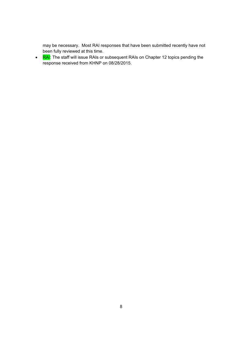
Table 12.2-23 provides the airborne radioactivity concentrations and DAC fractions for the main cubicles in the reactor containment, auxiliary building, and compound building.
Equilibrium airborne radioactivity concentrations in rooms, cubicles, and other areas during normal operation are calculated based on the following equation:
CA =LCP
(λV+F)
Where:
CA = airborne concentration in each cubicle (Bq/cm3)
L = leak rate (cm3/min)
C = radioactive concentration of liquid or gas (Bq/cm3)
P = fraction of activity released to air
λ = decay constant (min-1)
V = enclosed room volume (cm3)
F = air exhaust flow rate (cm3/min)
The equation above represents the solution of a differential equation in equilibrium conditions in which there is no airborne radioactivity in the ventilation airflow(s) entering the area under consideration. To accommodate situations in which airborne radioactivity is in one or more ventilation airflow streams entering the area of concern, additional term(s) are added to the basic differential equation. Assumptions and parameters used in the airborne source term calculations are provided in Table 12.2-26.
12.2.3 Sources Used in NUREG-0737 Post-Accident Shielding Analysis
Item II.B.2.3 of NUREG-0737 (Reference 4) clarifies the requirement for providing reasonable assurance that areas that require post-accident personnel access or contain safety-related equipment are adequately shielded in the vicinity of systems that may contain highly radioactive materials as a result of a DBA.
Rev. 0
Response to Source Term Audit Attachment (1/7)
41342
줄 긋기
41342
설명선
Minimum HVAC flow rates

APR1400 DCD TIER 2
12.2-61
Table 12.2-26 (3 of 8)
Auxiliary and Compound Building
Cubicle Volume
(m3) Leak Sources and
Number of Sources Leak Rate (L/min)
Source Terms (1), (2)
HVAC Flow (m3/hr)
CS Pump and Miniflow HX Rm
461 Pump seal (1) Flange (4)
Valve 1″ (4) Valve 4″ (2)
Valve 14″ (1)
1.67E-04 2.00E-03 6.66E-04 1.33E-03 2.33E-03
IRWST 170
SI Pump Rm 762 Pump seal (1) Flange (3)
Valve 4″ (4) Valve 10″ (1)
1.67E-04 1.40E-03 2.66E-03 1.67E-03
IRWST 850
Floor Drain Sump Pump Rm
94.9 Evaporation from sump
6.74E-02 0.1 PCA 680
Pipe Chase and Valve Rm (055-A14C)
1,246 Valve 18″ (2) Valve 20″ (1)
5.98E-03 3.33E-03
IRWST 170
Shutdown Cooling HX Rm 1,155 Valve 1.5″ (1) Valve 10″ (2)
2.50E-04 3.33E-03
IRWST 170
Rev. 0
Response to Source Term Audit Attachment (2/7)
41342
설명선
Minimum HVAC flow rate
Sangho Kang
줄 긋기

APR1400 DCD TIER 2
12.2-62
Table 12.2-26 (4 of 8)
Cubicle Volume
(m3) Leak Sources and
Number of Sources Leak Rate (L/min)
Source Terms (1), (2)
HVAC Flow (m3/hr)
Charging Pump Rm 1,156 Pump Seal (1) Flange (3)
Valve 1″ (1) Valve 3″ (4) Valve 4″ (2)
8.33E-04 1.40E-03 1.67E-04 2.00E-03 1.33E-03
VCT – Halogens
RCS – NG
850
Charging Pump Miniflow HX Rm
187 Valve 2.5″ (1) 4.16E-04 VCT – Halogens
RCS – NG
170
Equipment Drain Tank Rm 501 Flange (2) Valve 1″ (1) Valve 6” (1)
9.99E-04 1.67E-03 9.99E-04
EDT 170
Reactor Drain Pump Rm 200 Pump Seal (1) Flange (4)
8.33E-04 2.00E-03
RDT 850
Gas Stripper Rm 697 Flange (1) 5.00E-04 Gas Stripper 1,444
Filter and Demi. Valve Area 174 Valve 3″ (1) Valve 3″ (27)
5.00E-04 1.40E-02
RDT 1.0 PCA
1,529
Rev. 0
Response to Source Term Audit Attachment (3/7)
41342
줄 긋기
41342
설명선
Minimum HVAC flow rate
Sangho Kang
줄 긋기

APR1400 DCD TIER 2
12.2-63
Table 12.2-26 (5 of 8)
Cubicle Volume
(m3) Leak Sources and
Number of Sources Leak Rate (L/min)
Source Terms (1), (2)
HVAC Flow (m3/hr)
SFP Cleanup Pump Rm 224 Flange (6) Valve 4″ (3) Valve 6″ (4)
5.00E-03 2.00E-03 4.01E-03
SFP 510
Reactor Makeup Water Pump Rm
168 Flange (8) Pump Seal (2)
1.67E-03 4.01E-03
RMWT 340
Holdup Pump Rm 11,000 Flange (8) Pump Seal (2)
1.67E-03 4.01E-03
Holdup Tank
340
Valve Rm (120-A23A) 331 Valve 3″ (1) Valve 3″ (1) Valve 3″ (1)
5.00E-04 5.00E-04 5.00E-04
1.0 PCA RMWT BAST
510
Valve Rm (063-P07) 762 Flange (6) Valve 2” (9)
Valve 2.5” (2)
3.00E-03 3.00E-03 8.33E-04
1.0 PCA 340
Equipment Waste Pump Rm
138 Pump Seal (1) Flange (6)
Valve 2″ (2) Valve 3″ (6)
8.44E-03 3.00E-03 6.66E-04 3.00E-03
0.32 PCA 510
Equipment Waste Tank Rm 221 Flange (2) 9.99E-04 Equipment Waste Tank
510
Rev. 0
Response to Source Term Audit Attachment (4/7)
41342
줄 긋기
41342
설명선
Minimum HVAC flow rate
Sangho Kang
줄 긋기

APR1400 DCD TIER 2
12.2-64
Table 12.2-26 (6 of 8)
Cubicle Volume
(m3) Leak Sources and
Number of Sources Leak Rate (L/min)
Source Terms (1), (2)
HVAC Flow (m3/hr)
Floor Drain Pump Rm 413 Pump seal (1) Flange (2)
Valve 2″ (4) Valve 3″ (12)
1.67E-02 5.98E-03 1.33E-03 5.98E-03
0.44 PCA 1,359
Normal Sump Pump Rm 68.5 Flange (4) Valve 3″ (2)
Evaporation from sump
2.00E-03 9.99E-04 4.92E-02
0.01 PCA 1,019
Chemical Waste Pump Rm 215 Pump seal (2) Flange (10)
Valve 3″ (11) Valve 2″ (2)
1.67E-02 5.00E-03 5.49E-03 6.66E-04
0.01 PCA 1,104
Floor Drain Tank Rm 184 Flange (2) 9.99E-04 Floor Drain Tank
170
Chemical Waste Tank Rm 331 Flange (2) 9.99E-04 Chemical Waste Tank
170
Rev. 0
Response to Source Term Audit Attachment (5/7)
41342
줄 긋기
41342
설명선
Minimum HVAC flow rate
Sangho Kang
줄 긋기

APR1400 DCD TIER 2
12.2-65
Table 12.2-26 (7 of 8)
Cubicle Volume
(m3) Leak Sources and
Number of Sources Leak Rate (m3/min)
Source Terms (1), (2)
HVAC Flow (m3/hr)
Detergent Waste Tank and Pump Rm
657 Pump seal Flange (4)
Valve 2″ (2) Valve 3″ (3) Valve 4″ (7)
Evaporation from sump
1.67E-05 2.00E-06 6.66E-07 1.50E-06 4.66E-06 3.51E-05
Detergent Waste Tank
170
Chemical Drain Sump Pump Rm
119 Flange (2) Valve 2″ (1)
Evaporation from sump
8.93E-07 3.33E-07 4.92E-05
0.01 PCA 934
Monitor Tank Rm 88.6 Flange (4) 2.00E-06 Monitor Tank
170
Monitor Tank Pump Rm 197 Pump seal (2) Flange (10)
Valve 2.5″ (9) Valve 3″ (2)
Valve 4″ (14)
1.53E-05 5.00E-06 3.75E-06 9.99E-07 9.31E-06
Monitor Tank
170
Valve Rm (085-P06) 180 Valve 4” (1) 6.66E-07 1.0 PCA (Except for
NG)
170
Rev. 0
Response to Source Term Audit Attachment (6/7)
41342
줄 긋기
41342
설명선
Minimum HVAC flow rate
Sangho Kang
줄 긋기

APR1400 DCD TIER 2
12.2-66
Table 12.2-26 (8 of 8)
Cubicle Volume
(m3) Leak Sources and
Number of Sources Leak Rate (m3/min)
Source Terms (1), (2)
HVAC Flow (m3/hr)
Valve Rm (085-P15) 263 Valve 3″ (2) Valve 6″ (4)
5.00E-07 4.01E-06
1 PCA (Except for
NG)
510
Valve Rm (085-P16) 269 Valve 4″ (1) 6.66E-07 0.32 PCA 1,444
Valve 6″ (2) 2.00E-06 0.32 PCA
Valve 6″ (3) 3.00E-06 0.1 PCA
Valve 6″ (1) 9.99E-07 0.44 PCA
Valve 4″ (2) 1.33E-06 0.01 PCA
(1) PCA: Fraction of primary coolant activity concentrations
(2) NG: Noble gases
Rev. 0
Response to Source Term Audit Attachment (7/7)
41342
줄 긋기
41342
설명선
Minimum HVAC flow rate
Sangho Kang
줄 긋기