
SUBMITTAL DATA: PVA-A30AA7 &...
8
Job Name: System Reference: Date: Indoor Unit: PVA-A30AA7 Outdoor Unit: PUZ-HA30NHA5 INDOOR UNIT FEATURES • Ducted air handler provides a solution to cool and heat large zones • Highly efficient totally enclosed ECM motor • Selectable external static pressure: 0.30, 0.50 and 0.80 in.WG with 3 fan speeds at each static setting • 1 inch R4.2 fiberglass free insulation reduces condensation and boosts efficiency • Positive pressure cabinet with air leakage of less than 1.0% at 1.0 in.WG • Unique blow through design allows simple coil cleaning when the blower is removed • Multi-position installation: horizontal (left or right), vertical (up or down). For downflow configurations, the CMA-1 is recommended for proper management of condensate to prevent water blow-off in certain conditions • Optional electric heat kit for additional heat capacity • Optional humidifier control and ERV control OUTDOOR UNIT FEATURES • Variable speed INVERTER-driven compressor • High heating capacity: flash injection circuit maintains 100% heating capacity at 5°F outdoor temperature • Wide heating range: heating performance down to -13°F (average of 80% heating capacity) • High speed heating at start up: Hyper-Heating INVERTER ® reduces the time for heating at start up by about half compared to standard models • Suction accumulator pre-charged with refrigerant volume for piping length up to 100 ft. • Twinning of two indoor units possible with the 36 kBtu/h model • High pressure/temperature protection SUBMITTAL DATA: PVA-A30AA7 & PUZ-HA30NHA5 30,000 BTU/H AIR HANDLER HEAT PUMP SYSTEM Specifications are subject to change without notice. © 2018 Mitsubishi Electric Trane HVAC US LLC. All rights reserved. P-SERIES
Transcript of SUBMITTAL DATA: PVA-A30AA7 &...
Job Name:
System Reference: Date:
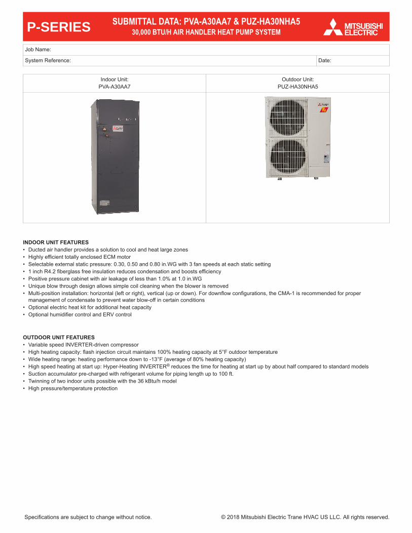
Indoor Unit:PVA-A30AA7
Outdoor Unit:PUZ-HA30NHA5
INDOOR UNIT FEATURES• Ducted air handler provides a solution to cool and heat large zones• Highly efficient totally enclosed ECM motor• Selectable external static pressure: 0.30, 0.50 and 0.80 in.WG with 3 fan speeds at each static setting• 1 inch R4.2 fiberglass free insulation reduces condensation and boosts efficiency • Positive pressure cabinet with air leakage of less than 1.0% at 1.0 in.WG• Unique blow through design allows simple coil cleaning when the blower is removed• Multi-position installation: horizontal (left or right), vertical (up or down). For downflow configurations, the CMA-1 is recommended for proper
management of condensate to prevent water blow-off in certain conditions• Optional electric heat kit for additional heat capacity• Optional humidifier control and ERV control
OUTDOOR UNIT FEATURES• Variable speed INVERTER-driven compressor• High heating capacity: flash injection circuit maintains 100% heating capacity at 5°F outdoor temperature• Wide heating range: heating performance down to -13°F (average of 80% heating capacity)• High speed heating at start up: Hyper-Heating INVERTER® reduces the time for heating at start up by about half compared to standard models• Suction accumulator pre-charged with refrigerant volume for piping length up to 100 ft.• Twinning of two indoor units possible with the 36 kBtu/h model• High pressure/temperature protection
SUBMITTAL DATA: PVA-A30AA7 & PUZ-HA30NHA530,000 BTU/H AIR HANDLER HEAT PUMP SYSTEM
Specifications are subject to change without notice. © 2018 Mitsubishi Electric Trane HVAC US LLC. All rights reserved.
P-SERIES

Model NumberIndoor Unit PVA-A30AA7
Outdoor Unit PUZ-HA30NHA5
Cooling1
Maximum Capacity Btu/h 30,000
Rated Capacity Btu/h 28,500
Minimum Capacity Btu/h 18,000
Maximum Power Input W 2,500
Rated Power Input W 2,280
Moisture Removal Pints/h 7.0
Sensible Heat Factor 0.70
Power Factor % 92.6
Heating at 47°F2
Maximum Capacity Btu/h 34,000
Rated Capacity Btu/h 32,000
Minimum Capacity Btu/h 18,000
Maximum Power Input W 3,240
Rated Power Input W 2,590
Power Factor % 93.8
Heating at 17°F3
Maximum Capacity Btu/h 32,000
Rated Capacity Btu/h 22,600
Maximum Power Input W 4,930
Rated Power Input W 2,740
Heating at 5°F4Maximum Capacity Btu/h 32,000
Maximum Power Input W 5,320
Efficiency
SEER 17.0
EER1 12.5
HSPF (IV) 9.7
COP at 47°F2 3.62
COP at 17°F in Maximum Capacity 1.90
COP at 5°F in Maximum Capacity 1.76
ENERGY STAR® Certified (ENERGY STAR products are third-party certified byan EPA-recognized Certification Body)
Yes
Electrical
Voltage, Phase, Frequency 208 / 230V, 1-phase, 60 Hz
Guaranteed Voltage Range V AC 198 – 253
Voltage: Indoor - Outdoor, S1-S2 V AC 208V / 230
Voltage: Indoor - Outdoor, S2-S3 V DC 24
Voltage: Indoor - Remote controller V DC 12
Recommended Fuse/Breaker Size A 30
Recommended Wire Size (Indoor - Outdoor) AWG 14
Indoor Unit
MCA A 4.13
Fan Motor Full Load Amperage A 3.30
Fan Motor Output W 244
Airflow Rate, Dry CFM 613-744-875
SPECIFICATIONS: PVA-A30AA7 & PUZ-HA30NHA5
Specifications are subject to change without notice. © 2018 Mitsubishi Electric Trane HVAC US LLC. All rights reserved.

Model NumberIndoor Unit PVA-A30AA7
Outdoor Unit PUZ-HA30NHA5
Airflow Rate, Wet CFM n/a
External Static Pressure in.WG 0.30-0.50-0.80
Sound Pressure Level dB(A) 30-34-38
Drain Pipe Size In. (mm) 3/4 FPT (19.05)
Condensate Lift Mechanism, Maximum Distance Ft. (m) n/a
Heat Exchanger Type Plate fin coil
External Finish Color Galvanized steel cabinet-Powder coatedSlate Gray
Unit Dimensions // Grille Dimensions
W: In. (mm) 21 (534)
D: In. (mm) 21-5/8 (548)
H: In. (mm) 54-1/4 (1378)
Unit Weight Lbs. (kg) 141 (64)
Indoor Unit OperatingTemperature Range
Cooling Intake Air Temp (Maximum / Minimum) °F 90 DB, 73 WB / 66 DB, 59 WB
Heating Intake Air Temp (Maximum / Minimum) °F 82 DB / 50 DB
Outdoor Unit
MCA A 28
MOCP A 40
Fan Motor Full Load Amperage A 0.4+0.4
Fan Motor Output W 86+86
Airflow Rate CFM 3,530
Refrigerant Control Electronic Expansion Valve
Defrost Method Reverse Cycle
Heat Exchanger Type Cross fin
Sound Pressure Level, Cooling1 dB(A) 52
Sound Pressure Level, Heating2 dB(A) 53
Compressor Type INVERTER-Driven Twin Rotary
Compressor Model ANB33FJEMT
Compressor Rated Load Amps A 18
Compressor Locked Rotor Amps A 27.5
Compressor Oil Type // Charge oz. FV50S // 45
External Finish Color Ivory Munsell 3Y 7.8/1.1
Base Pan Heater n/a
Unit Dimensions
W: In. (mm) 37-3/8 (950)
D: In. (mm) 13 + 1-3/16 (330 + 30)
H: In. (mm) 53-1/8 (1,350)
Package Dimensions
W: In. (mm) 40-15/16 (1,040)
D: In. (mm) 17-11/16 (450)
H: In. (mm) 56-11/16 (1,440)
Unit Weight Lbs. (kg) 265 (120)
Package Weight Lbs. (kg) 289 (131)
SPECIFICATIONS: PVA-A30AA7 & PUZ-HA30NHA5
Specifications are subject to change without notice. © 2018 Mitsubishi Electric Trane HVAC US LLC. All rights reserved.

Model NumberIndoor Unit PVA-A30AA7
Outdoor Unit PUZ-HA30NHA5
Outdoor Unit OperatingTemperature Range
Cooling Intake Air Temp (Maximum / Minimum) °F 115 DB / 0* DB
Heating Intake Air Temp (Maximum / Minimum) °F 70 DB, 59 WB / -13 DB, -13 WB
Thermal Lock-out / Re-start Temperatures** °F n/a
RefrigerantType R410A
Charge Lbs, oz 12
Piping
Gas Pipe Size O.D. (Flared) In.(mm) 5/8 (15.88)
Liquid Pipe Size O.D. (Flared) In.(mm) 3/8 (9.52)
Maximum Piping Length Ft. (m) 245 (75)
Maximum Height Difference Ft. (m) 100 (30)
Maximum Number of Bends 15
Notes
AHRI Rated Conditions(Rated data isdetermined at a fixedcompressor speed)
1Cooling (Indoor // Outdoor) °F 80 DB, 67 WB // 95 DB, 75 WB2Heating at 47°F (Indoor // Outdoor) °F 70 DB, 60 WB // 47 DB, 43 WB3Heating at 17°F (Indoor // Outdoor) °F 70 DB, 60 WB // 17 DB, 15 WB
Conditions 4Heating at 5°F (Indoor // Outdoor) °F 70 DB, 60 WB // -4 DB, -5 WB
*Wind baffles required to operate below 23°F DB in cooling mode. PUZ with wind baffle: 0°F - 115°F.**System cuts out in heating mode to avoid thermistor error and automatically restarts at these temperatures.
SPECIFICATIONS: PVA-A30AA7 & PUZ-HA30NHA5
Specifications are subject to change without notice. © 2018 Mitsubishi Electric Trane HVAC US LLC. All rights reserved.

Signal Receiver □ PAR-SA9CA-E
Wireless Remote Controller □ PAR-FL32MA-E
Wireless Remote Receiver □ PAR-FA32MA-E
Backlit, Wall-mounted, Wireless Controller □ MHK1
Portable Central Controller □ MCCH1
Wired MA Controller □ PAR-33MAA
Simple MA Controller □ PAC-YT53CRAU
Touch MA Controller □ PAR-CT01MAU-SB
Wired Remote Sensor □ PAC-SE41TS-E
Wireless Temperature and Humidity Sensor □ PAC-USWHS003-TH-1
Outside Air Sensor for MHK1 □ MOS1
Wireless Interface □ PAC-USWHS002-WF-1
Thermostat Interface □ PAC-US444CN-1
kumo station® □ PAC-WHS01HC-E
USNAP Interface □ PAC-WHS01UP-E
IT Extender □ PAC-WHS01IE-E
BACnet® and Modbus Interface □ PAC-UKPRC001-CN-1
External Fan / Heater Control Relay Adapter □ CN24RELAY-KIT-CM3
Connector cable for remote display □ PAC-SA88HA-EP
Connector for CN32 (remote on/off) □ PAC-SE55RA-E
Remote Operation Adapter (with wire terminals for remote ON/OFF and operation status/ error)1 □ PAC-SF40RM-E
Blue Diamond Sensor Extension Cable—15 Ft. □ C13-103
MegaBlue Advanced Blue Diamond Condensate Pump w/ Reservoir & Sensor □ X87-835 - 110 to 250V
MaxiBlue Advanced Blue Diamond Mini Condensate Pump w/ Reservoir & Sensor (208/230V) up to 48,000 Btu/h[recommended]
□ X87-721 - 208/230V
MegaBlue Blue Diamond Condensate Pump (110-230V) up to 170,000 Btu/h □ X87-835
Drain Pan Level Sensor (Control for indoor unit shut off to prevent drain pan overflow) □ DPLS2
3 Pole Disconnect Switch (30A/600VUL) [fits 2"X4" utility] - Black □ TAZ-MS303
Separate Power Terminal Block Kit □ SPTB1
Electric Heat Lockout Control □ ETC-211000-MIT
Electric Heat Kit for Multi-position AHU □ EH03-MPA-M(B)
Electric Heat Kit for Multi-position AHU □ EH05-MPA-M(B)
Electric Heat Kit for Multi-position AHU □ EH08-MPA-M(B)
Electric Heat Kit for Multi-position AHU □ EH10-MPA-M(B)1 Unable to use with wireless remote controller
ACCESSORIES: PVA-A30AA7
Specifications are subject to change without notice. © 2018 Mitsubishi Electric Trane HVAC US LLC. All rights reserved.
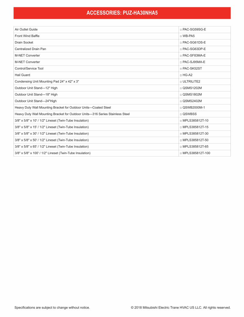
Air Outlet Guide □ PAC-SG59SG-E
Front Wind Baffle □ WB-PA5
Drain Socket □ PAC-SG61DS-E
Centralized Drain Pan □ PAC-SG63DP-E
M-NET Converter □ PAC-SF83MA-E
M-NET Converter □ PAC-SJ95MA-E
Control/Service Tool □ PAC-SK52ST
Hail Guard □ HG-A2
Condensing Unit Mounting Pad 24" x 42" x 3" □ ULTRILITE2
Outdoor Unit Stand—12" High □ QSMS1202M
Outdoor Unit Stand—18" High □ QSMS1802M
Outdoor Unit Stand—24"High □ QSMS2402M
Heavy Duty Wall Mounting Bracket for Outdoor Units—Coated Steel □ QSWB2000M-1
Heavy Duty Wall Mounting Bracket for Outdoor Units—316 Series Stainless Steel □ QSWBSS
3/8" x 5/8" x 10' / 1/2" Lineset (Twin-Tube Insulation) □ MPLS385812T-10
3/8" x 5/8" x 15' / 1/2" Lineset (Twin-Tube Insulation) □ MPLS385812T-15
3/8" x 5/8" x 30' / 1/2" Lineset (Twin-Tube Insulation) □ MPLS385812T-30
3/8" x 5/8" x 50' / 1/2" Lineset (Twin-Tube Insulation) □ MPLS385812T-50
3/8" x 5/8" x 65' / 1/2" Lineset (Twin-Tube Insulation) □ MPLS385812T-65
3/8" x 5/8" x 100' / 1/2" Lineset (Twin-Tube Insulation) □ MPLS385812T-100
ACCESSORIES: PUZ-HA30NHA5
Specifications are subject to change without notice. © 2018 Mitsubishi Electric Trane HVAC US LLC. All rights reserved.
PVA-A30AA7
Spe
cific
atio
ns a
re s
ubje
ct to
cha
nge
with
out n
otic
e.
© 2
016
Mits
ubis
hi E
lect
ric U
S, I
nc.
17
6OU
TLIN
ES &
DIM
ENSI
ONS
IND
OO
R U
NIT
PVA
-A12
, 18,
24,
30,
36,
42A
A7
(18-3/16)(20X24X1) (22-13/16X15-7/8)
(31-3/16)(18-13/16) (15-1/8) (10-1/2) (54-1/4) (29-1/16) (37-9/16)
(25) (22-13/16) (19-1/8) (12-1/2) (31-7/16) (41-1/2) (33-5/8) (22-3/16)
(21)
(20X20X1) (18-13/16X15-7/8)
Model A B C D E F G H J Gas pipe Liquid pipe
PVA-A30AA4477 382.6 266.5 1378 737 953.5
PVA-A36AA4 635 579 484.6 317.5 1511(59-1/2)
798.5 1053 853.5 563
PVA-A42AA4
Model Nominal Filter size Duct Connection
PVA-A30AA4
PVA-A36AA4
PVA-A42AA4
(5/8) (3/8)
461534508X609.6X25.4
508X508X25.4
579X402
477X402J
77.8(3-1/8)
66(2-5/8)
36.8(1-1/2)
43(1-3/4) 8(3/8)
92(3-5/8) 30(1-3/16)
43(1-3/4)8(3/8)
55(2-3/16)
548(21-5/8)117.4 (4-5/8) 402(15-7/8)
B(Duct) 28.8(1-3/16)76(3)C
A
D
525.
5(20
-3/4
)50
.8(2
)47
0(18
-9/1
6)
H55
(2-3
/16)
G70
(2-1
3/16
)
8(3/
8)
F55
(2-3
/16)
E24
(15/
16)
13.2
(9/1
6)
Control box
Air filter
Air outlet
Air inlet
(Duct)
Refrigerant pipingbrazing connection(gas)Refrigerant pipingbrazing connection(liquid)
Primary drain pipe(Gravity drain)ø19.05(3/4) 3/4"FPT
Secondary drain pipe(Emergency draining)ø19.05(3/4) 3/4"FPT
Primary drain pipe(Gravity drain)ø19.05(3/4) 3/4"FPT(Horizontal left)
(Horizontal Right)
Secondary drain pipe(Emergency draining)ø19.05(3/4) 3/4"FPT
Primary drain pipe(Gravity drain)ø19.05(3/4) 3/4"FPT
Secondary drain pipe(Emergency draining)ø19.05(3/4) 3/4"FPT
Terminal block(Indoor / Outdoor unit connection)
Terminal block(Remote controller transmission)
2-ø4.6 Burring Holesfor electric heat installation
ø26 Knockout Hole(Remote controller transmission)
ø26 Knockout Hole
ø26 Knockout Hole
ø26 Knockout Hole
(Indoor / Outdoor unit connection)
(Indoor /Outdoor unit connection)
(Remote controller transmission)
792Ø15.88 Ø9.52
Note 1.Keep the service space for maintenance at the front.
Unit:mm(in.)
Top
Topview
Front
Bottom
Bottomview
view
Left sideview
Right sideview
1
3
3
2
1
2
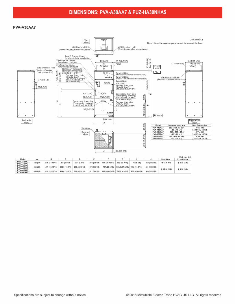
Model �Nominal Filter Size Duct ConnectionPVA-A12AA7 508 x 406.4 x 25.4
(20 x 16 x 1)376 x 402
(14-13/16 x 15-7/8)PVA-A18AA7PVA-A24AA7 508 x 508 x 25.4
(20 x 20 x 1)477 x 402
(18-13/16 x 15-7/8)PVA-A30AA7PVA-A36AA7 508 x 609.6 x 25.4
(20 x 24 x 1)579 x 402
(22-13/16 x 15-7/8)PVA-A42AA7
Unit: mm (in.)Model A B C D E F G H J �Gas Pipe �Liquid Pipe
PVA-A12AA7 432 (17) 376 (14-13/16) 281 (11-1/8) 224 (8-7/8) 1275 (50-1/4) 680 (26-13/16) 823 (32-7/16) 735.5 (29) 360 (14-3/16) Φ 12.7 (1/2) Φ 6.35 (1/4)PVA-A18AA7PVA-A24AA7 534 (21) 477 (18-13/16) 382.6 (15-1/8) 266.5 (10-1/2) 1378 (54-1/4) 737 (29-1/16) 953.5 (37-9/16) 792 (31-3/16) 461 (18-3/16)
Φ 15.88 (5/8) Φ 9.52 (3/8)PVA-A30AA7PVA-A36AA7 635 (25) 579 (22-13/16) 484.6 (19-1/8) 317.5 (12-1/2) 1511 (59-1/2) 798.5 (31-7/16) 1053 (41-1/2) 853.5 (33-5/8) 563 (22-3/16)PVA-A42AA7
(18-3/16)(20X24X1) (22-13/16X15-7/8)
(31-3/16)(18-13/16) (15-1/8) (10-1/2) (54-1/4) (29-1/16) (37-9/16)
(25) (22-13/16) (19-1/8) (12-1/2) (31-7/16) (41-1/2) (33-5/8) (22-3/16)
(21)
(20X20X1) (18-13/16X15-7/8)Model A B C D E F G H J Gas pipe Liquid pipe
P VA-A30AA4477 382.6 266.5 1378 737 953.5
P VA-A36AA4 635 579 484.6 317.5 1511(59-1/2)
798.5 1053 853.5 563P VA-A42AA4
Model Nominal Filter si ze Duct Connection
P VA-A30AA4
P VA-A36AA4
P VA-A42AA4
(5/8) (3/8)
461534508X609.6X25.4
508X508X25.4
579X402
477X402J
77.8(3-1/8)
66(2-5/8)
36.8(1-1/2)
43(1-3/4) 8(3/8)
92(3-5/8) 30(1-3/16)
43(1-3/4)8(3/8)
55(2-3/16)
548(21-5/8)117.4 (4-5/8) 402(15-7/8)
B(Duct) 28.8(1-3/16)76(3)C
A
D
525.
5(20
-3/4
)50
.8(2
)47
0(18
-9/1
6)
H55
(2-3
/16)
G70
(2-1
3/16
)
8(3/
8)
F55
(2-3
/16)
E24
(15/
16)
13.2
(9/1
6)
Control b ox
Air filter
Air outlet
Air inlet
(Duct)
Ref rigerant piping�are connection(gas)Ref rigerant piping�are connection(liquid)
P rimary drain pipe(G ravity drain)ø19.05(3/4) 3/4"FPT
Seconda ry drain pipe(Emergency d raining)ø19.05(3/4) 3/4"FPT
P rimary drain pipe(G ravity drain)ø19.05(3/4) 3/4"FPT(Ho rizontal left)
(Ho rizontal Right)
Seconda ry drain pipe(Emergency d raining)ø19.05(3/4) 3/4"FPT
P rimary drain pipe(G ravity drain)ø19.05(3/4) 3/4"FPT
Seconda ry drain pipe(Emergency d raining)ø19.05(3/4) 3/4"FPT
Terminal block(Indoor / Outdoor unit connection)
Terminal block(Remote controller t ransmission)
2-ø4.6 Bur ring Holesfor elect ric heat installation
ø26 Kno ckout Hole(Remote controller t ransmission)
ø26 Kno ckout Hole
ø26 Kno ckout Hole
ø26 Kno ckout Hole
(Indoor / Outdoor unit connection)
(Indoor /Outdoor unit connection)
(Remote controller t ransmission)
792Ø15.88 Ø9.52
Note 1. Keep the se rvice space for maintenance at the front .
Unit:mm(in.)
Top
Topview
Front
Bottom
Bottomview
view
Left sideview
Right sideview
1
3
3
2
1
2
DIMENSIONS: PVA-A30AA7 & PUZ-HA30NHA5
Specifications are subject to change without notice. © 2018 Mitsubishi Electric Trane HVAC US LLC. All rights reserved.

PUZ-HA30NHA5
10
6O
UTLIN
ES AN
D D
IMEN
SION
S
Min. 1000mm<39-3/8>
Min. 150mm<5-29/32>
Min. 10mm<3/8>
Min. 10mm<3/8>
FREE
<Foundation bolt height>
FOUNDATION
Service space
Terminal BlockLeft···Power supply wiringRight····Indoor/Outdoor wiring
Earth terminal
Service panel
Handle
1
2
23<2
9/32
>
1076
<42-
3/8>
*1
447<
17-1
9/32
>
*1
443<
17-7
/16>
Handle
Front piping cover
Rear piping cover
Air Discharge
Rear Air Intake
Side Air Intake
31<1
-7/3
2>
145<5-23/32>
145<5-23/32>
220<8-21/32>30<1-3/16>
145<5-23/32>
81<3
-3/1
6>21
9<8-
5/8>
71<2
-13/
16>
71<2-13/16>
Bottom piping hole(Knockout)
Drain hole5-[33<1-5/16>
Handle
Side Air Intake
Air intake
Rear Air Intake
Handle Handle
40<1-9/16>
74<2-19/32>
When installing the conduit.Set the attachment to the inner side of each panel.
2-[22.2<7/8>
1/2 Conduit attachment45<1-25/32> 40<1-9/16>
65<2-9/16>92<3-5/8>
27<1
-1/1
6>55
<2-3/
16>
23<2
9/32
>73
<2-7
/8>
63<2
-1/2
>
Rear piping hole(Knockout)
Rear trunking hole(Knockout)
Conduit hole (2-[27<1-1/16>Knockout)
[92<3-5/8>
19<3/4> 55<2-3/16>
92<3-5/8>
75<2-31/32> 40<1-9/16>
73<2
-7/8
>63
<2-1
/2>
23<2
9/32
>27
<1-1
/16>
92<3
-5/8
>
Right piping hole(Knockout) Right trunking hole
(Knockout)
Conduit hole (2-[27<1-1/16>Knockout)
[92<3-5/8>
92<3-5/8>65<2-9/16>
45<1-25/32>40<1-9/16>
27<1
-1/1
6>55
<2-3/
16>
23<2
9/32
>73
<2-7
/8>
63<2
-1/2
>
Front piping hole(Knockout)
Front trunking hole(Knockout)
Conduit hole (2-[27<1-1/16>Knockout)
[92
<3-5/8>
371<
14-1
9/32
>
330<
13>
30<1
-3/1
6>
175<6-7/8> 600<23-5/8> 175<6-7/8>
42<1-21/32>66<2-5/8>
950<37-13/32>
322<12-11/16>
1350
<53-
5/32
>
635<
25>
19<3
/4>
417<
16-1
3/32
>
370<
14-9
/16>
2-U Shaped notched hole(Foundation Bolt M10<W3/8>)
56<2
-7/3
2>
28<1
-3/3
2>
53<2
-3/3
2>
45<1
-25/
32>
2-12 o 36 Oval hole(Foundation Bolt M10<W3/8>)
1····Refrigerant GAS pipe connection (FLARE)[15.88<5/8>2····Refrigerant LIQUID pipe connection (FLARE)[ 9.52<3/8>*1 ····Indication of STOP VALVE connection location.
Example of Notes
1 FREE SPACE (Around the unit) 2 SERVICE SPACE 3 FOUNDATION BOLTS 4 PIPING-WIRING DIRECTIONS
Piping Knockout Hole Details
The diagram below shows abasic example.Explanation of particular details aregiven in the installation manuals, etc.
Dimensions of space neededfor service access areshown in the below diagram.
Please secure the unit firmlywith 4 foundation (M10<W3/8>)bolts. (Bolts and washers mustbe purchased locally.)
Piping and wiring connectionscan be made from 4 directions:front, right, rear and below.
Min.10mm<3/8> Mi
n.50
0mm
<19-1
1/16>
Min.500mm<19-11/16>
Min.
150m
m<5
-29/32
>
Min.
30mm
<1-3/
16>
OCH607
Unit : mm<inch>
FORM# PVA-A30AA7 / PUZ-HA30NHA5 - 201810
1340 Satellite Boulevard, Suwanee, GA 30024Toll Free: 800-433-4822 www.mehvac.com
DIMENSIONS: PVA-A30AA7 & PUZ-HA30NHA5
Specifications are subject to change without notice. © 2018 Mitsubishi Electric Trane HVAC US LLC. All rights reserved.


![[Model Name] [Service Ref.] PUZ-ZM35VKA PUZ-ZM50VKA PUZ ... · puz-zm60vha(-et) puz-zm71vha(-et) symbol 1 g r01 e72 221fan motor 1 1 mf1 2 g r01 e12 115propeller fan 1 1 3 g r01 e09](https://static.fdocuments.in/doc/165x107/5e1925b50df5c673806c1e57/model-name-service-ref-puz-zm35vka-puz-zm50vka-puz-puz-zm60vha-et-puz-zm71vha-et.jpg)