Subgrade Models for Rigid Pavements. Development of theories for analyzing rigid pavements include...
30
Subgrade Models for Rigid Pavements
-
date post
22-Dec-2015 -
Category
Documents
-
view
228 -
download
3
Transcript of Subgrade Models for Rigid Pavements. Development of theories for analyzing rigid pavements include...

Subgrade Models for Rigid Pavements
Subgrade Models for Rigid Pavements
Development of theories for analyzing rigid pavements include the choice of a subgrade model. When the chosen model closely represents the actual situation, the resulting analyses are useful tools for design engineers.
The model for analyzing a concrete pavement consists generallyof an elastic plate that rests on a foundation model. Whereas the equations for plates that are subjected to mechanical load and thermaleffects are well established , the modeling of the supporting base is not.
The simplest and most popular model for the foundation base isthe one proposed by Winkler (1867), consisting of closely spaced independent springs. For static loads, the response of this base modelis the same as the response of a liquid base. An early solution for the infinite plate on a Winkler base subjected to a vertical load was presented by Hertz (1884). Solutions for a semi-infinite plate with a “free” boundary - for interior, edge, and corner loads - were presentedby Westergaard (1926, 1939, 1947). These solutions have been at the

heart of slab design since the 1920’s. According to Iounnides et al.(1985), several investigators have noted repeatedly that althoughthe Westergaard solution agreed fairly well with their observation for the interior condition, it failed to give even a close estimate of the response for edge and corner loads.
It appears that this failure has less to do with the accuracy of theWestergaard solutions than with the inadequacy of the Winkler foundation model, which consists of closely spaced independent springs. From an interior load, the interaction between these springs is provided by the pavement, whereas along the “free” edge, these interactions - which take place in an actual subgrade - are missing. They are included in the Pasternak and Kerr subgrade models.

kw
P
w
k
G
P
(I) Winkler Model (II) Pasternak Model
P
G
kl
ka
(III) Kerr Model

0
1.0
0.6
0.2
1.4
q=3472
lb/in2
Dis
pla
cem
ets,
in
-0.4 -0.2 0 0.2 0.4
x/L
Kerr ModelPasternak ModelFinite Element
Winkler Model
L/2 L/2
q
H(E,v)
π
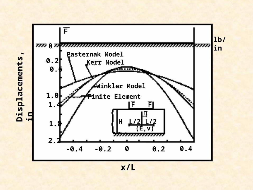
-0.4 -0.2 0 0.2 0.4
0
1.0
0.6
0.2
1.4
1.8
2.2
Pasternak ModelKerr Model
Winkler Model
Finite Element
lb/in
H(E,v)
L/2 L/2
F F
F
x/L
Dis
pla
cem
ents
, in
π

-0.4 -0.2 0 0.2 0.4
0
200
600
1000
Pasternak Model
Winkler Model
Kerr Model
Finite Element
x/L
Mo
men
ts,
Kip
s in
/in
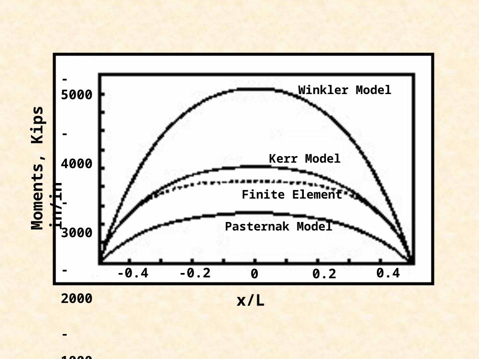
-5000
-4000
-3000
-2000
-1000
0 -0.4 -0.2 0 0.2 0.4
x/L
Mo
men
ts,
Kip
s in
/in
Pasternak Model
Kerr Model
Finite Element
Winkler Model

P
Most Foundation models are in between these two.
Winkler FoundationP(x,y)=k w(x,y)
w
Figure 1
Elastic Foundation
P
(a)
Figure 2
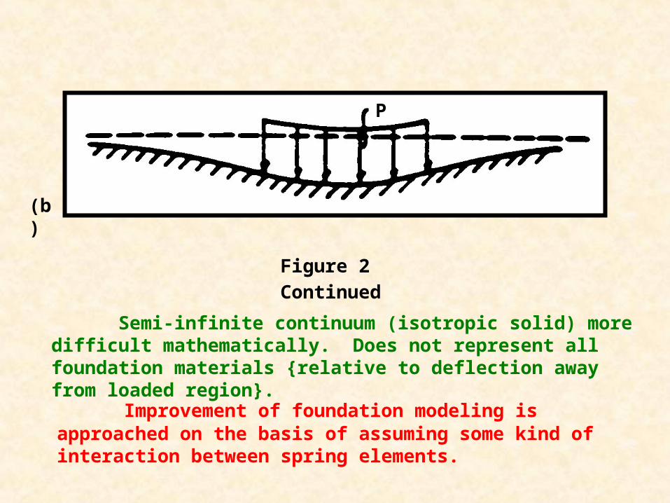
Semi-infinite continuum (isotropic solid) more difficult mathematically. Does not represent all foundation materials {relative to deflection away from loaded region}.
Improvement of foundation modeling is approached on the basis of assuming some kind of interaction between spring elements.
P
Figure 2 Continued
(b)
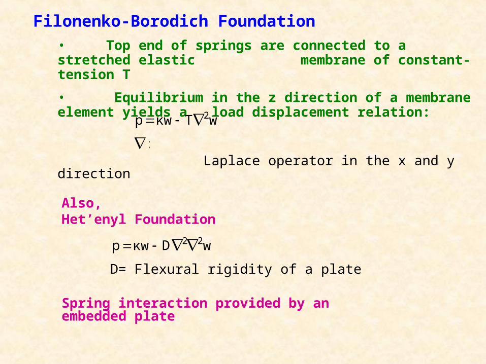
Filonenko-Borodich Foundation
• Top end of springs are connected to a stretched elastic membrane of constant- tension T
• Equilibrium in the z direction of a membrane element yields a load displacement relation:
Laplace operator in the x and y direction
Also,Het’enyl Foundation
D= Flexural rigidity of a plate
Spring interaction provided by an embedded plate
wTκwp 2
:
wDκwp 22

T T
stretched membrane, plate in bonding, or shear layer
Spring interaction is a function of T
Figure 3

Assumes existence of shear interaction between spring elements. Connection of springs by incompressible vertical elements which deform by transverse shear.
Pasternak Foundation
δx
δw
w
x x
z
Figure 4
Shear Intaction
dxδx
δww
dxx
xzτ

dyδ
δNN
y
yy
y
y+dy
y
x
xNy
PNx
dxδ
δNN
x
xx
qs
Vertical Equilibrium
Figure 4 Continued
dxx

Pasternak Foundation
Valasov Foundation
Uses a ‘continuum’ approach by means of a variational method. Certain restrictions are imposed on possible deformations of the elastic layer. A load-deflection relation is obtained which can be re-dined to match the Pasternak expression.
Plate Element
Element of Shear Layer
dxδ
δNN
x
xx dy
δ
δNN
y
yy
qs
y
y+dyy
x x+axx
qs
msy
msx
dxdy
Figure 12
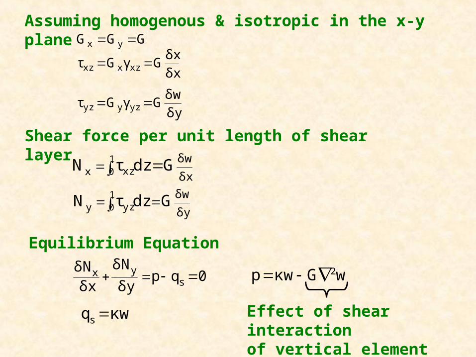
Assuming homogenous & isotropic in the x-y plane
Shear force per unit length of shear layer
δy
δwGdzτN yzy10
δx
δwGdzτN xzx10
Equilibrium Equation
0qpδy
δN
δxδN
syx
κwqs
wGκwp 2
Effect of shear interaction of vertical element
GGG yx
δx
δxGγGτ xzxxz
δy
δwGγGτ yzyyz
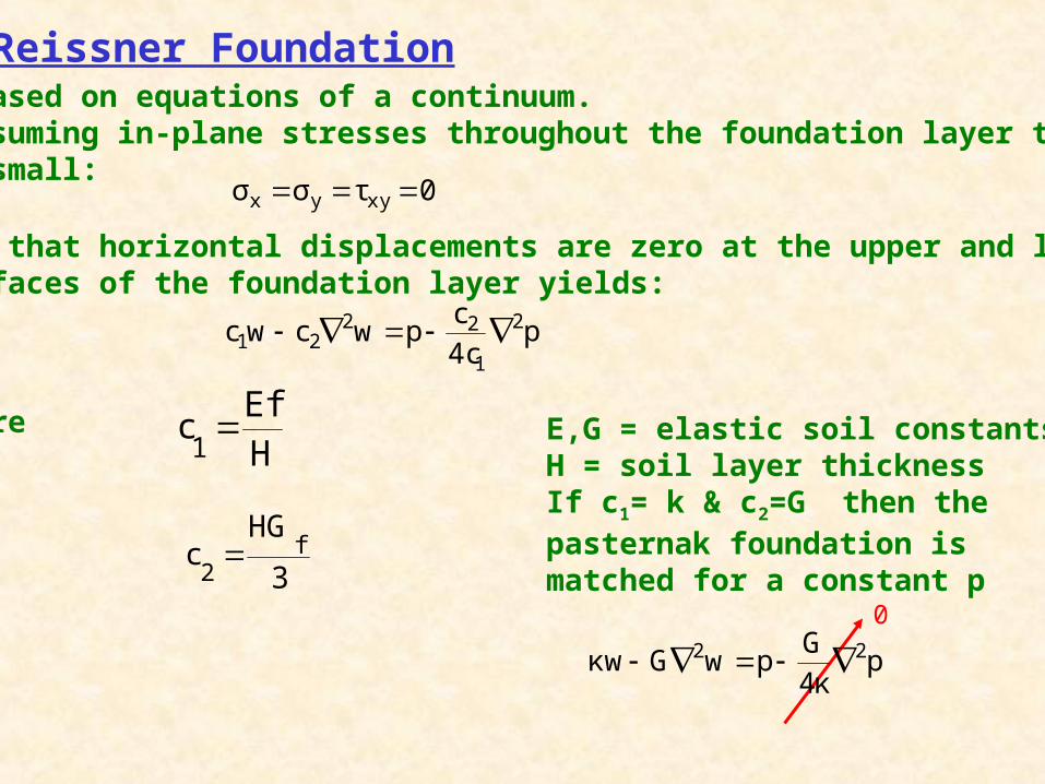
Reissner Foundation• Based on equations of a continuum.•Assuming in-plane stresses throughout the foundation layer tobe small:
and that horizontal displacements are zero at the upper and lowersurfaces of the foundation layer yields:
where E,G = elastic soil constantsH = soil layer thicknessIf c1= k & c2=G then the pasternak foundation is matched for a constant p
H
Efc
1
3
HGc f
2
0τσσ xyyx
p4c
cpwcwc 2
1
2221
p4κ
GpwGκw 22
0

A consequence of the above assumption is that the shear stresses zx and xy are independent of z and thus are constant throughout the depth of the foundation for a given surface point (x,y); physically a nonrealistic result particularly for relatively thick foundation layers. However, in view of the fact that foundation models are introduced to study the response of the foundation surface to loads and not the stresses caused within the foundation, this deficiency may in general be of no serious consequence.

Deflection profiles for typical highway pavement under a point load

Interior Loading Deflction Profiles
-0.001
0
0.001
0.002
0.003
0.004
0.005
0.006
0.007
0.008
0.009
0.01
0 20 40 60 80 100 120 140 160
Horizontal offset (in.)
Vert
ical
Def
lecti
on
(in
.)
Elastic Solid
Dense Liquid
Kerr
Two-Parameter
Figure 2a

Edge Loading Deflection Profiles
0
0.005
0.01
0.015
0.02
0.025
0.03
0.035
0 10 20 30 40 50 60 70 80 90 100
Horizontal Offset (in.)
Ve
rtic
al
De
fle
cti
on
(in
.)
Dense Liquid
Elastic Solid
Kerr
Two-Parameter
Figure 2a

Corner Loading Deflection Profiles
0
0.01
0.02
0.03
0.04
0.05
0.06
0.07
0.08
0 20 40 60 80 100 120 140 160
Horizontal Offset (in.)
Ve
rtic
al D
efl
ec
tio
n (
in.)
Kerr
Two-Parameter
Elastic Solid
Dense Liquid
Figure 2a

Deflection profiles for typical highway pavement under a uniformly distributed load
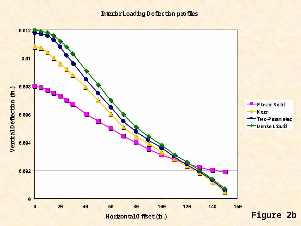
Interior Loading Deflection profiles
0
0.002
0.004
0.006
0.008
0.01
0.012
0 20 40 60 80 100 120 140 160
Horizontal Offset (in.)
Ver
tica
l D
efle
ctio
n (
in.)
Elastic Solid
Kerr
Two-Parameter
Dense Liquid
Figure 2b
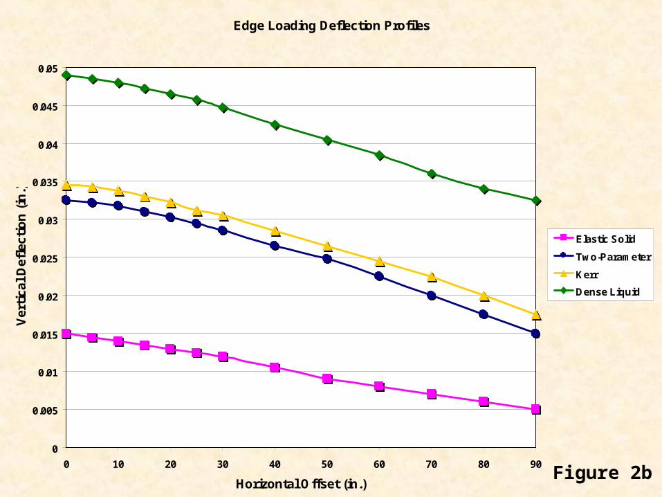
Edge Loading Deflection Profiles
0
0.005
0.01
0.015
0.02
0.025
0.03
0.035
0.04
0.045
0.05
0 10 20 30 40 50 60 70 80 90
Horizontal Offset (in.)
Ver
tica
l D
efle
ctio
n (
in.)
Elastic Solid
Two-Parameter
Kerr
Dense Liquid
Figure 2b

Corner Loading Deflection Profiles
0
0.02
0.04
0.06
0.08
0.1
0.12
0 20 40 60 80 100 120 140 160
Horizontal Offset (in.)
Ver
tica
l D
efle
ctio
n (
in.)
Elastic Solid
Two-Parameter
Kerr
Dense Liquid
Figure 2b

Shear LayerPlate in Bending
Figure 7p
q q
Reaction Distribution
Bending Moment
Figure 8
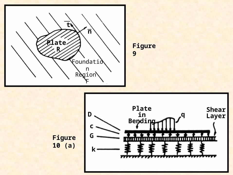
Plate R
FoundationRegion
F
tn
Figure 9
D
c
G
k
qPlate in Bending
Shear Layer
Figure 10 (a)

q
p
Figure 10 (b)

q
r
a a
Figure 11