
Style 240 Molded PTFE Lined Insert - MIPR...
12
Transcript of Style 240 Molded PTFE Lined Insert - MIPR...


Style 240 Spherical Molded PTFE Lined Insert Expansion Joints are designed for piping systems to absorb pipe movements, relieve stress, reduce system noise/vibration, compensate for misalignment/offset and to protect rotating mechanical equipment against start-up surge forces.
The molded style 240 single sphere designed bellows are inherently stronger than the conventional hand-built style spool arch type. Internal pressure within a “sphere” is exerted in all directions, distributing forces evenly over a larger area. The spherical design “flowing arch” reduces turbulence and sediment buildup.
Features and Benefits:
Absorbs Directional MovementThermal movements appear in any rigid pipe system due to temperature changes. The Style 240 spherical arch expansion joints allow for axial compression or axial extension, lateral deflection as well as angular movement. (Note: Rated movements in this publication are based on single plane movements. Multiple movement conditions are based on a multiple movement calculation. )
Easy Installation with Rotating Metallic FlangesThe floating metallic flanges freely rotate on the bellows, compensating for mating flange misalignment, thus speeding up installation time. Gaskets are not required with the Style 240, provided the expansion joints are mated against a flat face flange as required in the installation instructions.
Flange Materials/DrillingThe Style 240 molded expansion joints are furnished complete with plated carbon steel flanges for corrosion protection. 304 or 316 stainless steel flanges are available upon request as well as ANSI 250/300 lb., DIN PN10 and PN16 drilling.
Absorbs Vibration, Noise and ShockThe Style 240 molded expansion joints effectively dampen and insulate downstream piping against the transmission of noise and vibration generated by mechanical equipment. Noise and vibration caused by equipment can cause stress in pipe, pipe guides, anchors and other equipment downstream. Water hammer and pumping impulses can also cause strain, stress or shock to a piping system. Install the Style 240 molded expansion joints to help compensate for these system pressure spikes.
Wide Service Range with Low Cost Compared to conventional hand-built spool type joints, you will invest less money when specifying the mass-produced, consistent high quality, molded single sphere expansion joints.
Material IdentificationAll Style 240 molded expansion joints have branded elastomer designations. PTFE Neoprene Cover (NT) elastomer designated joints meet the Coast Guard Requirements and conform to ASTM F1123-87.
Information subject to change without notice.
Protecting Piping and Equipment Systems from Stress/Motion
Style 240 Molded PTFE Lined Insert
1
The 240-A and 240-C are reinforced with Polyester.1. NT elastomer designated joints meet the Coast Guard Requirements and conform to ASTM F 1123-87 and are marked accordingly.2. Products with PTFE loose liner are not intended for vacuum service.3. All elastomers above are not intended for steam service.
Notes:
240 Single Sphere
Table 1: Available Styles • Materials
240-
C
Material Code
Cover Elastomer 1
Tube Elastomer 2
Maximum Operating Temp. °F
Identifying Color
Band/Label
X /ET EPDM PTFE 250° Red
X /ET-9 EPDM PTFE 265° DBL Red
X /NT Neoprene PTFE 225° Yellow

2
Style 240 PTFE Lined Insert Performance Data
Thrust Factor=“Effective Area”
NOTES:
1. Movements shown in the above tables are non-concurrent.
2. Calculation of Thrust (Thrust Factor). When expansion joints are installed in the pipeline, the static portion of the thrust is calculated as a product of the area of the I.D. of the arch of the expansion joint times the maximum pressure (design, test or surge) that will occur in the line. The result is a force expressed in pounds. Take design, surge or test pressure X thrust factor to calculate end thrust.
3. Pressure rating is based on 170oF operating temperature. The pressure rating is reduced at higher temperatures.
4. Pressures shown at maximum “operating pressure”. Test pressure is 1.5 times “operating pressure”. Burst pressure is 4 times “operating pressure”. If factory hydro-test is required, an additional joint per size must be purchased and tested. Once hydro-tested this joint may not be sent to field for installation as the beaded end will have taken a (compressed) set and can not be reused.
5. In addition to standard 150 lb. drilled flanges, can provide expansion joints listed above in 300 lb. drilling, Metric PN10 and PN16 drilling.
Table 2: Sizes • Movements • Pressures • Flange Standards • Weights
NOMINALPipe Size
I.D.
NeutralLength
Style Number
1
240 Movement Capability: From Neutral Position 1 Pressure 3 Standard Flange Drilling
Dimensions 5 Weight in lbs
Axial
Comp
ressi
onIn
ches
Axial
Exten
sion
Inch
es
Later
al De
flecti
onIn
ches
Angu
lar D
eflec
tion
Degr
ees
Thru
st Fa
ctor 2
Posit
ive 4
PSIG
Flang
e O.D
. Inc
hes
Bolt C
ircle
Inch
es
Numb
er of
Hole
s
Size o
f Hole
sIn
ches
Exp.
Joint
&
Flang
es
Cont
rol U
nit Se
t (2
Rod
)
1(25) 5.00 240-C 0.500 0.625 0.562 22 2.21 87 4.25 3.13 4 0.625 3.8 3.3
1.25(32) 5.00 240-C 0.500 0.625 0.562 8 3.17 87 4.63 3.5 4 0.625 5.0 3.3
1.5(40) 5.00 240-C 0.500 0.625 0.562 22 3.24 87 5.0 3.88 4 0.625 5.1 4.6
2(50)
5.00 6.00
240-C 240-A
0.500 0.562
0.625 0.562 0.562 22 3.53 87 6.0 4.75 4 0.750 7.1 6.3
2.5(65)
5.00 6.00
240-C 240-A
0.500 0.562
0.625 0.562 0.562 22
21 5.52 87 7.0 5.5 4 0.750 10.6 12.0 7.6
3(80)
5.00 6.00
240-C 240-A
0.500 0.562
0.6250.562 0.562 20
19 6.68 87 7.5 6.0 4 0.750 13.3 13.8 8.3
4(100)
5.00 6.00
240-C 240-A
0.500 0.562
0.625 0.562 0.562 16
15 11.34 87 9.0 7.5 8 0.750 16.5 17.5 7.4
5(125)
5.00 6.00
240-C 240-A
0.500 0.562
0.625 0.562 0.562 13
22 15.01 87 10.0 8.5 8 0.875 20.3 21.8 8.3
6(150)
5.00 6.00
240-C 240-A
0.500 0.562
0.6250.562 0.562 11
10 20.64 87 11.0 9.5 8 0.875 22.6 24.0 10.4
8(200)
5.00 6.00
240-C 240-A
0.500 0.562 0.562 0.562 8 31.81 87 13.5 11.75 8 0.875 35.5
38.5 13.4
10(250)
5.00 8.00
240-C 240-A
0.500 0.562 0.562 0.562 7
6 51.93 87 16.0 14.25 12 1.000 49.3 53.6
21.021.3
12(300)
5.00 8.00
240-C 240-A
0.500 0.562
0.6250.562 0.562 6
5 68.94 87 19.0 17.0 12 1.000 73.4 80.0
26.527.0
we

Style 240 PTFE Lined Drilling Chart
3
Table 3: Flange Drilling
NOMINALPipe Size
Inch(mm)
American 125/150#Conforms to ANSI B16.1 and B16.5
American 250/300#Conforms to ANSI B16.1 and B16.5
Flang
e Thic
knes
s
Flang
e O.D
.
Bolt C
ircle
No. o
f Hole
s
Drille
d Hole
Size
Flang
e Thic
knes
s
Flang
e O.D
.
Bolt C
ircle
No. o
f Hole
s
Hole
Size
1(25)
0.55 (14.0)
4.25 (108.0)
3.13 (79.4) 4 0.62
(15.9) 0.63
(16.0) 4.88
(124.0) 3.5
(88.9) 4 0.75 (19.1)
1.25(32)
0.55 (14.0)
4.63 (118.0)
3.5 (88.9) 4 0.62
(15.9) 0.63
(16.0) 5.25
(133.0) 3.88
(98.4) 4 0.75 (19.1)
1.5(40)
0.55 (14.0)
5.0 (127.0)
3.88 (98.4) 4 0.62
(15.9) 0.63
(16.0) 6.12
(156.0) 4.50
(114.3) 4 0.88 (22.2)
2(50)
0.63 (16.0)
6.0 (152.0)
4.75 (120.7) 4 0.75
(19.1) 0.71
(18.0) 6.50
(165.0) 5.00
(127.0) 8 0.75 (19.1)
2.5(65)
0.71 (18.0)
7.0 (178.0)
5.5 (139.7) 4 0.75
(19.1) 0.71
(18.0) 7.5
(191.0)5.88
(149.2) 8 0.88 (22.2)
3(80)
0.71 (18.0)
7.5 (191.0)
6.0 (152.4) 4 0.75
(19.1) 0.79
(20.0) 8.25
(210.0) 6.62
(168.2) 8 0.88 (22.2)
4(100)
0.71 (18.0)
9.0 (229.0)
7.5 (190.5) 8 0.75
(19.1) 0.79
(20.0) 10.0
(254.0) 7.88
(200.0) 8 0.88 (22.2)
5(125)
0.79 (20.0)
10.0 (254.0)
8.5 (215.9) 8 0.88
(22.2) 0.87
(22.0) 11.0
(279.0) 9.25
(235.0) 8 0.88 (22.2)
6(150)
0.87 (22.0)
11.0 (279.0)
9.5 (241.3) 8 0.88
(22.2) 0.87
(22.2) 12.5
(318.0) 10.62
(269.9) 12 0.88 (22.2)
8(200)
0.87 (22.0)
13.5 (343.0)
11.75 (298.5) 8 0.88
(22.2) 0.95
(24.0) 15.0
(381.0) 13.0
(330.2) 12 1.00 (25.4)
10(250)
0.95(24.0)
16.0 (406.0)
14.25 (362.0) 12 1.00
(25.4) 1.02
(26.0) 17.5
(445.0) 15.25
(387.4) 16 1.13(28.6)
12(300)
0.95 (24.0)
19.0 (483.0)
17.0 (431.8) 12 1.00
(25.4) 1.02
(26.0) 20.5
(521.0) 17.75
(450.9) 16 1.25 (31.8)

4
Table 3: Flange Drilling
NOMINALPipe Size
Inch(mm)
Metric SeriesConforms to I.S.O. 2084-1974 Table NP10 Holes to
I.S.O. /R-273
Metric SeriesConforms to I.S.O. 2084-1974 Table NP16 Holes to
I.S.O. /R-273Fla
nge T
hickn
ess
Flang
e O.D
.
Bolt C
ircle
No. o
f Hole
s
Hole
Size
Flang
e Thic
knes
s
Flang
e O.D
.
Bolt C
ircle
No. o
f Hole
s
Hole
Size
1(25)
0.63 (16.0)
4.53 (115.0)
3.35 (85.0) 4 0.55
(14.0) 0.63
(16.0) 4.53
(115.0) 3.35
(85.0) 4 0.55(14.0)
1.25(32)
0.63 (16.0)
5.51 (140.0)
3.94 (85.0) 4 0.71
(18.0) 0.63
(16.0) 5.51
(140.0) 3.94
(100.0) 4 0.71(18.0)
1.5(40)
0.63 (16.0)
5.91 (150.0)
4.33 (110.0) 4 0.71
(18.0) 0.63
(16.0) 5.91
(150.0) 4.33
(110.0) 4 0.71(18.0)
2(50)
0.71 (18.0)
6.50 (165.0)
4.92 (125.0) 4 0.71
(18.0) 0.71
(18.0) 6.50
(165.0) 4.92
(125.0) 4 0.71(18.0)
2.5(65)
0.71 (18.0)
7.25 (185.0)
5.71 (145.0) 4 0.71
(18.0) 0.71
(18.0) 7.28
(185.0) 5.71
(145.0) 4 0.71(18.0)
3(80)
0.79 (20.0)
7.87 (200.0)
6.3 (160.0) 8 0.71
(18.0) 0.79
(20.0) 7.87
(200.0) 6.30
(160.0) 8 0.71(18.0)
4(100)
0.79 (20.0)
8.66 (220.0)
7.09 (180.0) 8 0.71
(18.0) 0.79
(20.0) 8.66
(220.0) 7.09
(180.0) 8 0.71(18.0)
5(125)
0.87 (22.0)
9.84 (250.0)
8.27 (210.0) 8 0.71
(18.0) 0.87
(22.0) 9.84
(250.0) 8.27
(210.0) 8 0.71(18.0)
6(150)
0.87 (22.0)
11.22 (285.0)
9.45 (240.0) 8 0.87
(22.0) 0.87
(22.0) 11.22
(285.0) 9.45
(240.0) 8 0.87(22.0)
8(200)
0.87 (22.0)
13.39 (340.0)
11.61 (295.0) 8 0.87
(22.0) 0.87
(22.0) 13.39
(340.0) 11.61
(295.0) 12 0.87(22.0)
10(250)
1.02 (26.0)
15.55 (395.0)
13.78 (350.0) 12 0.87
(22.0) 1.02
(26.0) 15.94
(405.0) 13.98
(355.0) 12 1.02(26.0)
12(300)
1.02 (26.0)
17.52 (445.0)
15.75 (400.0) 12 0.87
(22.0) 1.02
(26.0) 18.11
(460.0) 16.14
(410.0) 12 1.02(26.0)
Style 240 PTFE Lined Drilling Chart

5
Drilling Chart for Bolting Requirements
Metric Conversion Formula: Nominal I.D.: in. x 25 = mm; Dimensions/Thickness’: in. x 25.4 = mm. Notes:1. Flange Dimensions shown are in accordance with ANSI B16.1 and ANSI B16.5 Class 125/150, AWWA C-207-07, Tbl 2 and 3 - Class D, Table 4 - Class E. Hole size shown is 1/8” larger than AWWA Standard.2. Limit/Control Rod length is determined by neutral length of rubber expansion joint, rated extension, control rod plate thickness, mating flange thickness and number of nuts. Consult for rod lengths. 3. Adjacent mating flange thickness is required to determine overall rod length and compression sleeve length (if required). 4. Plate thickness is based on a maximum width would use to design a Limit/Control Rod plate.5. Control rod plate O.D. installed dimension is based on a maximum O.D. would supply.6. Control rod diameter is based on a maximum diameter would use to design a control rod.
Table 4: Standard Drilling for Rubber Expansion Joints
Thickness of Materials for Rubber Expansion Joints
Control Unit Plate Detail
Nominal Pipe Size Expansion Joint I.D.
Inch /(mm)
Flange Dimensions 1 Material Thickness 2
for Bolt Length RequirementsFla
nge O
.D.
Inch
/ (m
m)
Bolt C
ircle
Inch
/ (m
m)
Numb
er O
f Hole
s
Size O
f Hole
sIn
ch /
(mm)
Nomi
nal F
lange
/Be
aded
End T
hickn
ess
Inch
/ (m
m) (A
ppro
x. Va
lue)
Adjac
ent M
ating
3
Flang
e Thic
knes
s
Max.
Cont
rol 4
Ro
d Plat
e Thic
knes
sIn
ch /
(mm) Control Rod 5
Plate O.D.Inch / (mm)
Maximum 6
Rod Diameter
Inch / (mm)
1(25)
4.25 (108.00)
3.13 (79.50) 4 0.625
(15.87) 1.25
(31.75)
CUSTOMER
TO SPECIFY
MATING
FLANGE THICKNESS
0.375(9.53)
8.375(215.9)
0.625(15.9)
1.25(32)
4.63(118.00)
3.5(88.90) 4 0.625
(15.87)1.25
(31.75)0.375(9.53)
8.750(222.3)
0.625(15.9)
1.5(40)
5.0 (127.00)
3.88 (98.55) 4 0.625
(15.87)1.25
(31.75)0.375(9.53)
9.125(231.8)
0.625(15.9)
2(50)
6.00(152.00)
4.75(120.65) 4 0.750
(19.05) 1.25
(31.75)0.375(9.53)
10.125(257.2)
0.625(15.9)
2.5(65)
7.00(178.00)
5.50(139.70) 4 0.750
(19.05) 1.25
(31.75)0.375(9.53)
11.125(282.6)
0.625(15.9)
3(80)
7.50(191.00)
6.00(152.40) 4 0.750
(19.05) 1.25
(31.75)0.375(9.53)
11.625(295.3)
0.625(15.9)
4(100)
9.00(229.00)
7.50(190.50) 8 0.750
(19.05) 1.25
(31.75)0.375(9.53)
13.125(333.4)
0.625(15.9)
5(125)
10.00(254.00)
8.50(215.90) 8 0.875
(22.23) 1.50
(38.10)0.500
(12.70) 14.125(358.8)
0.625(15.9)
6(150)
11.00(279.00)
9.50(241.30) 8 0.875
(22.23) 1.50
(38.10)0.500
(12.70) 15.125(384.2)
0.625(15.9)
8(200)
13.50(343.00)
11.75(298.45) 8 0.875
(22.23) 1.50
(38.10)0.750
(19.05) 19.125(485.8)
1.000(25.4)
10(250)
16.00(406.00)
14.25(361.95) 12 1.000
(25.40) 1.50
(38.10)0.750
(19.05) 21.625(549.3)
1.000(25.4)
12(300)
19.00(483.00)
17.00(431.80) 12 1.000
(25.40) 1.50
(38.10)0.750
(19.05) 24.625(625.5)
1.000(25.4)
we
we
we
s u
s u
6
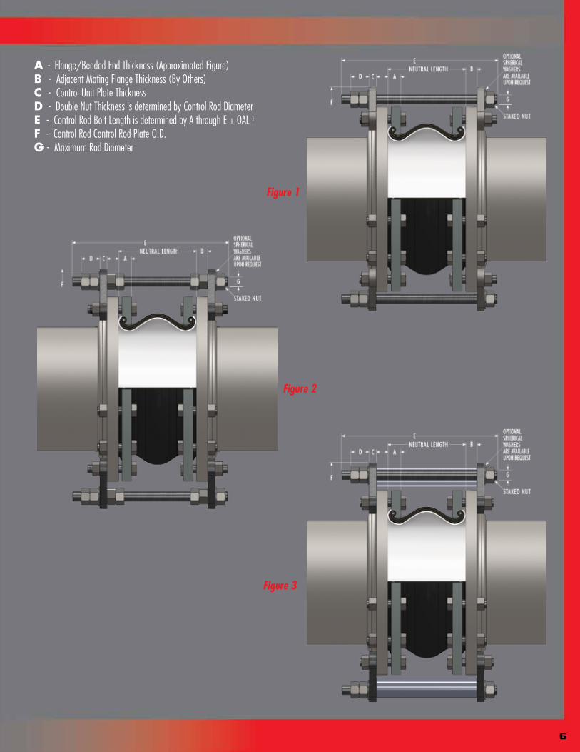
A - Flange/Beaded End Thickness (Approximated Figure)B - Adjacent Mating Flange Thickness (By Others)C - Control Unit Plate ThicknessD - Double Nut Thickness is determined by Control Rod DiameterE - Control Rod Bolt Length is determined by A through E + OAL 1F - Control Rod Control Rod Plate O.D.G - Maximum Rod Diameter
Figure 1
Figure 2
Figure 3

7
Limit RodsUse of Control Units with Rubber Expansion JointsDefinitionA control unit assembly is a system of two or more control rod units (limit rods, tie rods or compression sleeves) placed across an expansion joint from flange to flange to minimize possible damage caused by excessive motion of a pipeline. The control unit assemblies can be set at the maximum allowable expansion and/or contraction of the rubber expansion joint. When used in this manner, control units are an additional safety factor and can minimize possible damage to adjacent equipment.
Rubber expansion joints should be installed between two fixed anchor points in a piping system. The pipe system must be rigidly anchored on both sides of the expansion joint to control expansion or contraction of the line. Piping anchors must be capable of withstanding the line thrusts generated by internal pressure or wide temperature fluctuations.
When proper anchoring cannot be provided, CONTROL UNITS ARE REQUIRED. For un-anchored piping systems nuts shall be tightened snug against rod plate to prevent over-extension due to pressure thrust created by expansion joint. Refer to “Thrust Factor” in Table 2, note 5 in this manual. Please also see Table 7 for number of control rods recommended based on maximum serge for test pressure of the system
Listed below are three (3) control unit configurations supplied and are commonly used with rubber expansion joints in piping systems.
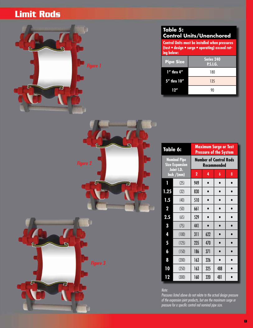
Figure 1Known as a LIMIT ROD, this control unit configuration will allow an expansion joint to extend to a predetermined extension setting. Nuts shall be field-set to no more than the maximum allowable extension movement of a rubber expansion joint (unless used in an un-anchored system). Refer to Table 2 in this manual for allowable movement capabilities. Spherical washers can also be furnished (upon request) to combat any “nut-to-plate” binding during offset. Consult the systems engineer for proper nut settings prior to system operation.
Figure 2Known as a LIMIT/CONTROL ROD, this control unit configuration is used to allow specified pipe expansion (expansion joint axial compression) and pipe contraction (expansion joint axial extension) movements. Nuts shall be field set to no more than the maximum allowable extension (unless used in an un-anchored pipe system) or compression of a rubber expansion joint. Refer to Table 2 in this manual for allowable movement capabilities. Internal and external nuts can also be field-set to allow for no movement in the horizontal plane. This setting will allow the rubber to move laterally while keeping expansion joint thrust forces low on adjacent equipment. Spherical washers can also be furnished (upon request) to combat any potential “nut-to-plate” binding during offset. Limit/Control rods with internal nuts must be specified at the time of inquiry. Consult the systems engineer for proper nut settings prior to system operation.
Figure 3 Known as a COMPRESSION SLEEVE, this configuration is used to allow for specified pipe expansion (expansion joint axial compression) and pipe contraction (expansion joint extension) movements. Nuts shall be field-set to no more than the maximum allowable extension (unless used in an un-anchored pipe system) of a rubber expansion joint. Refer to Table 2 in this manual for allowable movement capabilities. will manufacture each compression sleeve to allow for no axial movement unless otherwise specified by the purchaser. Compression sleeves shall be field-trimmed to meet required allowable axial movement as set forth by system requirements. Spherical washers can also be furnished (upon request) to combat any potential “nut-to-plate” binding during offset. Consult the systems engineer for proper sleeve lengths prior to system operation.
Important Control Unit Considerations The number of rods, control rod diameters and control rod plate thicknesses are important considerations when specifying control units for an application. As a minimum, specifying engineers or purchasers shall follow the guidelines as set forth in Appendix C of the Fluid Sealing Association’s Technical Handbook, Seventh Edition. engineer its control unit assemblies to system requirements. Our designs incorporate an allowable stress of 65% of material yield for each rod and plate (rod and plate material to be specified by purchaser). Therefore, it is important to provide pressure and temperature ratings to when requesting control units for rubber expansion joints. It is also important to provide adjacent mating flange thickness or mating specifications to ensure correct rod lengths are provided.
Installation Instructions for Limit Rods1. Assemble expansion joint between pipe flanges in its manufactured face-to-face length.
2. Assemble control rod plates behind pipe flanges as shown. Flange bolts or all-thread studs through the control rod plate must be longer to accommodate the plate thickness. Control rod plates should be equally spaced around the flange. Depending upon the size and pressure rating of the system, 2, 3, 4, or more control/limit rods may be required. Refer to Table 4 in this manual or to the Fluid Sealing Association’s Technical Handbook, Seventh Edition, for control rod pressure ratings.
3. Insert control/limit rods through top plate holes. Steel flat washers are to be positioned at outer plate surface.
4. If a single nut per unit is furnished, position this nut so that there is a gap between the nut and the steel flat washer. This gap is equal to the joint’s maximum extension (commencing with the nominal face-to-face length). To lock this nut in position, either “stake” the thread in two places or tack weld the nut to the rod. If two nuts are supplied, the nuts will create a “jamming” effect to prevent loosening. (Nuts should be snug against the flat washer and control rod plate when piping system is un-anchored.)
Note: Consult the manufacturer if there are any questions as to the rated compression and elongation. These two dimensions are critical in setting the nuts and sizing the compression pipe sleeve (if supplied).
5. If there is a requirement for compression pipe sleeves, an ordinary pipe may be used, sized in length to allow the joint to be compressed to its normal limit.
6. If there is a requirement for optional spherical washers, these washers are to be positioned at the inner and/or outer plate surface and backed up by movable double nuts.
We
We
8
Table 6: Maximum Surge or Test Pressure of the System
Nominal Pipe Size Expansion
Joint I.D. Inch /(mm)
Number of Control Rods Recommended
2 4 6 8
1 (25) 949 • • •
1.25 (32) 830 • • •
1.5 (40) 510 • • •
2 (50) 661 • • •
2.5 (65) 529 • • •
3 (75) 441 • • •
4 (100) 311 622 • •
5 (125) 235 470 • •
6 (150) 186 371 • •
8 (200) 163 326 • •
10 (250) 163 325 488 •
12 (300) 160 320 481 •
Note:Pressures listed above do not relate to the actual design pressure of the expansion joint products, but are the maximum surge or pressure for a specific control rod nominal pipe size.
Table 5: Control Units/UnanchoredControl Units must be installed when pressures(test • design • surge • operating) exceed rat-ing below:
Pipe Size Series 240P.S.I.G.
1” thru 4” 180
5” thru 10” 135
12” 90
Figure 1
Figure 3
Figure 2
Limit Rods

1. Service Conditions: Make sure the expansion joint rating for temperature, pressure, vacuum*, movements and selection of elastomeric materials match the system requirements. Contact the manufacturer if the system requirements exceed those of the expansion joint selected. (*Vacuum service for spherical rubber connectors: Vacuum rating is based on neutral installed length. These products should not be installed “extended” on vacuum applications.)
2. Alignment: Expansion joints are not designed to make up for piping misalignment errors. Piping misalignment should be no more than 1/8” in any direction. Misalignment of an expansion joint will reduce the rated movements and can induce severe stress of the material properties, thus causing reduced service life or premature failure.
3. Anchoring: Expansion joints should be located as close as possible to anchor points with proper pipe guides. Install expansion joints only on straight runs between anchors. It is recommended that control rods be installed on the expansion joint to prevent excessive movements from occurring due to pressure thrust of the line.
4. Pipe Support: Piping must be supported so expansion joints do not carry any pipe weight.
5. Mating Flanges: Install the expansion joint against the mating pipe flanges and install bolts so that the bolt head is against the expansion joint flange. Flange-to-flange dimension of the expansion joint must match the breech opening*. (*A spherical rubber connector must be pre-compressed 1/8” to 3/16” during installation in order to obtain a correct installed face-to-face dimension.)
Make sure the mating flanges are clean and are a flat-faced type. When attaching beaded end flange expansion joints to raised face flanges, the use of composite gaskets are required to prevent metal flange faces from cutting rubber bead during installation.
Never install expansion joints next to wafer type check or butterfly valves.
6. Bolting Torque: Table 8 shows the recommended torque values for non-metallic expansion joints with beaded end type-flanges: Tighten bolts in stages by alternating around the flange. Use the recommended torque values in Table 8 to achieve a good seal. Never tighten an expansion joint to the point that there is metal-to-metal contact between the expansion joint flanges and the mating flanges. A slight bulge in the rubber beaded end should create a flush tight seal. Note: Torque values are approximate due to mating flange surfaces, installation offsets, operating pressures and environmental conditions.
7. Storage: Ideal storage is in a warehouse with a relatively dry, cool location. Store flanges face down on a pallet or wooden platform. Do not store other heavy items on top of the expansion joints. Ten year shelf life can be expected with ideal conditions. If storage must be outdoors, place on a wooden platform and joints should not be in contact with the ground. Cover with a tarpaulin.
8. Large Joint Handling: Do not lift with ropes or bars through the bolt holes. If lifting through the bore, use padding or a saddle to distribute the weight. Make sure cables or forklift tines do not contact the rubber. Do not let expansion joints sit vertically on the edges of the flanges for any period of time.
9. Additional Tips: A. Do not insulate/cover over a rubber expansion joint. This prevents inspection of the tightness of the joint bolting. B. It is acceptable (but not necessary) to lubricate the expansion joint beaded end with a thin film of graphite dispersed in glycerin or water at time of installation to prevent damage. C. Do not weld in the near vicinity of a non-metallic joint. D. If expansion joints are to be installed underground, or will be submerged in water, contact manufacturer for specific recommendations. E. If the expansion joint will be installed outdoors, make sure the cover material will withstand ozone, sunlight, etc. F. Check the tightness of flanges two or three weeks after installation and retighten if necessary. Refer to Notes in Para 6. Bolting Torque. G. Expansion joint installation should be conducted by an authorized and qualified pipe fitter. H. While all expansion joints are guaranteed for a period of one year and designed for many years of service, it is suggested that expansion joints be routinely inspected based on service conditions.
Warning: Expansion joints may operate in pipelines or equipment carrying fluids and/or gasses at elevated temperature and pressures and may transport hazardous materials. Precautions should be taken to protect personnel in the event of leakage or splash. Rubber joints should not be installed in areas where inspection is impossible. Make sure proper drainage is available in the event of leakage when operating personnel are not available.
Installation Instructions for Non-Metallic Expansion
9

Joints with Beaded End Flanges
10
Table 7: Bolt-Torque
Nominal Pipe Size Expansion Joint I.D.
Inch /(mm)
Step 1FT-LBS(Nm)
RestStep 2 FT-LBS(Nm)
RestStep 3 FT-LBS(Nm)
1(25)
18(25)
30 Min
30(40)
60 Min
45-60(60-80)
1.25(32)
18(25)
30 Min
30(40)
60 Min
45-60(60-80)
1.5(40)
18(25)
30 Min
30(40)
60 Min
45-60(60-80)
2(50)
18(25)
30 Min
30(40)
60 Min
45-60(60-80)
2.5(65)
18(25)
30 Min
35(50)
60 Min
50-60(70-80)
3(80)
25(35)
30 Min
45(60)
60 Min
60-75(80-100)
4(100)
25(35)
30 Min
45(60)
60 Min
60-75(80-100)
5(125)
25(35)
30 Min
45(60)
60 Min
60-75(80-100)
6(150)
30(40)
30 Min
50(70)
60 Min
60-75(80-100)
8(200)
30(40)
30 Min
50(70)
60 Min
60-75(80-100)
10(250)
30(40)
30 Min
50(70)
60 Min
75-85(100-115)
12(300)
30(40)
30 Min
50(70)
60 Min
75-85(100-115)
Right:Weld neck
flanges with correct ID
prevent damage to rubber.
Tighten opposing nuts/bolts gradually according to the following sequence
A
Right:Flanges with
correct ID help prevent damage
to rubber.
Pipe Stop
C
Right:In case of B, D, F an additional
metal gasket can be used to
prevent damage to rubber.
E
Right:Well rounded smooth edge
prevents damage to rubber. G
Wrong:Insure mating
flange I.D. is flush with
rubber.
B
Wrong:Uneven end of pipe can cause
damage to rubber.
D
Wrong:Inner edge of flanges damages
rubber.F
Note: Bolt torque based on new bolts and nuts

Optional Spherical Washers
240-ITR Single Sphere