Study on the Application of an Axle Box Heating Detection
4
19 JR EAST Technical Review-No.22 S pecial edition paper e axle box temperature heating detection system was developed for early detection of abnormal heating of components of axle bearings—important running devices for railway rolling stock— so that critical accidents could be prevented. 1) 2) 3) e developed system is now being deployed for major lines in the greater Tokyo area. Early detection of abnormality of bearings is needed in regions with heavy snowfall too, so we examined functions for cold and snow resistance to apply the system for the greater Tokyo area to cold regions. We installed a prototype system that reflected the examination results at Ugo-Ushijima Station on the Uetsu Line (in Akita City) in the period from December 2010 to September 2011. Using that, we investigated the effects low temperature, snow cover, and snowfall have on performance. Development for System for Cold Regions 2 e developed system measures temperature of components of an axle box that holds bearings. Specifically, it is a system using contactless infrared temperature sensors (infrared radiation thermometers) installed facing axle boxes of running train cars as shown in Fig. 1. e system measures surface temperature of axle boxes obliquely from below, and it gives an alert if it detects that a designated temperature is exceeded. Wheel detectors that are installed on the rail determine the position of each axle box. By using three wheel detectors on each side, velocity of passing trains is calculated to identify the position of the axles. e system has a built-in heater to keep ambient temperature at 5 ºC or higher for stable operation of temperature sensors. As the sensors are an infrared type, there should be no obstacles between the system and the axle box to be measured. Furthermore, to apply the current system to cold regions, cold and snow resistance has to be enhanced. Taking into account those conditions and installation to lines along the coast of the Japan Sea (Uetsu Line and Ou Line), we set the following specification values for cold regions based on weather data in the previous five years at Niitsu, Akita, Odate and Hirosaki. Introduction 1 · Cold resistance: Lowest operation temperature -20 ºC · Snow resistance (snow cover): Largest snow depth 75 cm · Snow resistance (snowfall): Heaviest snowfall 40 cm/day 2.1 Snow Resistance Test (Snowfall) To see the effect of snowfall, we carried out snowfall simulation tests using actual snow and a screen (Fig. 2). In the test, we found some distorted waveforms of temperature measured with the temperature sensor caused by snowfall blocking the infrared light path. e test results, however, confirmed that the system did not make incorrect detection of temperature as being higher than actual temperature, even in snowfall of the simulation test level where accurate measurement was difficult because around 10 - 30% of the infrared light was shadowed (Fig. 3). Study on the Application of an Axle Box Heating Detection System to Cold Regions • Keywords: Axle bearing, Axle box, Temperature detection, Temperature sensor, Snow cover, Snowfall An axle box heating detection system completed in fiscal 2008 is being deployed for major line sections in the greater Tokyo area. As there is demand for this system in regions with heavy snowfall too, we examined functions for cold and snow resistance and developed an axle box heating detection system for cold regions. Bench tests and field verification of cold and snow resistance performance of the developed system proved that the system could work correctly to measure temperature of axle boxes at the level of snow cover seen in the winter of 2010 - 2011. * Technical Center, Research and Development Center of JR East Group ** Technical Center ( currently at TaKASAKI TETSUDO service Co., Ltd.) *** Technical Center (currently at East Japan Transport Technology Co., Ltd.) Yukio Kurosaki* Jun’ichiro Mishima * Yoshimitsu Sugiura * Keisuke Ishii*** Akira Yokokura * Satoshi Chiba** Axle box Temperature sensor Measures peak temperature at axle boxes. Fig. 1 Overview of Axle Box Heating Detection System
Transcript of Study on the Application of an Axle Box Heating Detection
19JR EAST Technical Review-No.22
Special edition paper
The axle box temperature heating detection system was developed for early detection of abnormal heating of components of axle bearings—important running devices for railway rolling stock—so that critical accidents could be prevented.1) 2) 3) The developed system is now being deployed for major lines in the greater Tokyo area. Early detection of abnormality of bearings is needed in regions with heavy snowfall too, so we examined functions for cold and snow resistance to apply the system for the greater Tokyo area to cold regions. We installed a prototype system that reflected the examination results at Ugo-Ushijima Station on the Uetsu Line (in Akita City) in the period from December 2010 to September 2011. Using that, we investigated the effects low temperature, snow cover, and snowfall have on performance.
Development for System for Cold Regions2
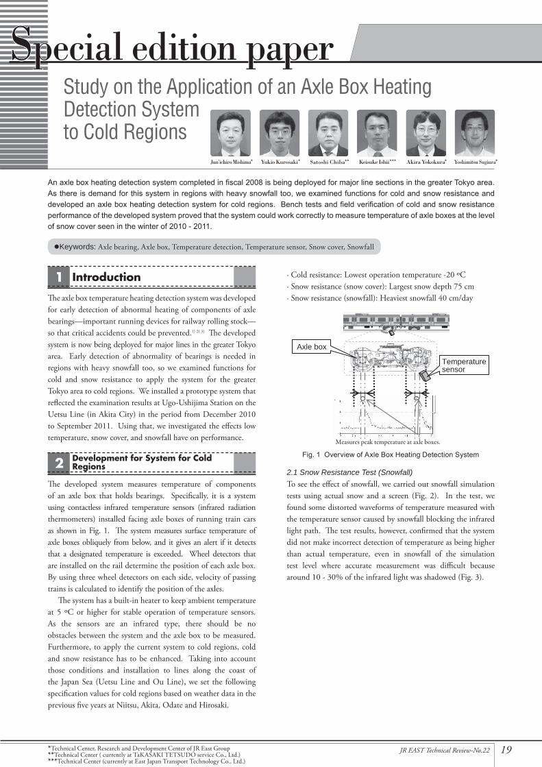
The developed system measures temperature of components of an axle box that holds bearings. Specifically, it is a system using contactless infrared temperature sensors (infrared radiation thermometers) installed facing axle boxes of running train cars as shown in Fig. 1. The system measures surface temperature of axle boxes obliquely from below, and it gives an alert if it detects that a designated temperature is exceeded. Wheel detectors that are installed on the rail determine the position of each axle box. By using three wheel detectors on each side, velocity of passing trains is calculated to identify the position of the axles.
The system has a built-in heater to keep ambient temperature at 5 ºC or higher for stable operation of temperature sensors. As the sensors are an infrared type, there should be no obstacles between the system and the axle box to be measured. Furthermore, to apply the current system to cold regions, cold and snow resistance has to be enhanced. Taking into account those conditions and installation to lines along the coast of the Japan Sea (Uetsu Line and Ou Line), we set the following specification values for cold regions based on weather data in the previous five years at Niitsu, Akita, Odate and Hirosaki.
Introduction1 · Cold resistance: Lowest operation temperature -20 ºC· Snow resistance (snow cover): Largest snow depth 75 cm· Snow resistance (snowfall): Heaviest snowfall 40 cm/day
2.1 Snow Resistance Test (Snowfall)To see the effect of snowfall, we carried out snowfall simulation tests using actual snow and a screen (Fig. 2). In the test, we found some distorted waveforms of temperature measured with the temperature sensor caused by snowfall blocking the infrared light path. The test results, however, confirmed that the system did not make incorrect detection of temperature as being higher than actual temperature, even in snowfall of the simulation test level where accurate measurement was difficult because around 10 - 30% of the infrared light was shadowed (Fig. 3).
Study on the Application of an Axle Box Heating Detection System to Cold Regions
•Keywords: Axle bearing, Axle box, Temperature detection, Temperature sensor, Snow cover, Snowfall
An axle box heating detection system completed in fiscal 2008 is being deployed for major line sections in the greater Tokyo area. As there is demand for this system in regions with heavy snowfall too, we examined functions for cold and snow resistance and developed an axle box heating detection system for cold regions. Bench tests and field verification of cold and snow resistance performance of the developed system proved that the system could work correctly to measure temperature of axle boxes at the level of snow cover seen in the winter of 2010 - 2011.
*Technical Center, Research and Development Center of JR East Group**Technical Center ( currently at TaKASAKI TETSUDO service Co., Ltd.)***Technical Center (currently at East Japan Transport Technology Co., Ltd.)
Yukio Kurosaki*Jun’ichiro Mishima* Yoshimitsu Sugiura*Keisuke Ishii*** Akira Yokokura*Satoshi Chiba**
Axle box
Temperature sensor
Measures peak temperature at axle boxes.
Fig. 1 Overview of Axle Box Heating Detection System

20 JR EAST Technical Review-No.22
Special edition paper
the side surface on the track side (Fig. 5). We also improved the heater as a measure against low temperature.
2.3 Cold Resistance TestTo check cold resistance performance, we installed a controller unit and temperature sensor unit, each with a heater, in a thermostatic chamber set at 20 ºC and carried out continuous operation testing for 25 hours. The test results proved that the temperature in each unit was kept at 5 ºC or higher and both units continued operating. The electric power of the heater required for the controller unit was found to be approx. 400 W (Fig. 6).
2.4 Second Snow Resistance Test (Snowfall)In order to quantify the snowfall simulation test results of section 2.1, we carried out snow resistance tests again at the Shiozawa Snow Testing Station of the Railway Technical Research Institute (Fig. 7). No distorted waveforms were observed under the test conditions this time (snowfall intensity “strong”: 3 cm/h or more). However, we decided to further conduct field verification tests because snow quality varies by location.
2.2 Snow Resistance Test (Snow Cover)To see the effect of snow cover, we installed a temperature sensor unit for the greater Tokyo area and an electric snow melting mat in the yard of the Odate Transport Depot (Odate City, Akita Prefecture, Fig. 4) and carried out snow resistance tests. The test results proved that snow on the front side of the unit could be melted even in snow cover of approx. 20 cm.
The window for the infrared sensor is located on the top of the unit for the greater Tokyo area, but we found it could be covered with snow. We thus decided to move the window to
Heat generator
Temperature sensor housing
Screen
Temperature waveform distorted by simulated snowfall
March 10, 2010 (approx. 20 cm snow cover)
March 18, 2010 (approx. 10 cm snow cover)
Dust prevention labyrinth
Temperature sensorWindow for sensor
Fig. 3 Temperature Waveform Measured in Snowfall Simulation Test
Fig. 2 Snowfall Simulation Test
Fig. 4 Outdoor Snow Covering Test (at Odate Transport Depot)
Fig. 6 Thermostatic Chamber
Fig. 5 Temperature Sensor Unit Designed for Cold Regions
Fig. 7 Snowfall Simulation Test

21JR EAST Technical Review-No.22
Special edition paper
Field Tests33.1 Installation of the Prototype SystemBased on the results of prior verification, we produced a prototype system with changes in the location of the sensor window and the power of the heater, and we installed that at Ugo-Ushijima Station for the field test. System configuration and photos of installation are shown in Fig. 8. Since the test location was in a single-line section, we installed temperature sensors at an angle of 90º to the rail too to check if there was any difference according to train running direction. Those sensors would be installed at 45º to the rail in the greater Tokyo area. We also changed the wheel detectors to models with a heater and moved those from the inside of the rail (flange side) as they are located in the greater Tokyo area to the outside of the rail (rim side) where less effect of snow cover would be expected.
Weather data of Akita City in 2010 - 2011 winter was as follows.· Lowest temperature -7.1 ºC (January 16 and 27, 2011)· Deepest snow cover 43 cm (February 11, 2011)· Heaviest snowfall 19 cm/day (February 10, 2011)(Source: website of the Japan Meteorological Agency)
Fig. 9 shows a train actually in operation passing the prototype system. The field tests demonstrated that the prototype system could make stable measurement for passing trains too, while the system for the greater Tokyo area measures temperature when a train enters a station to stop there. Almost no difference in measured temperature according to train running directions was observed either.
to Akita to Niigata
Distant view (1)
Camera image
Monitor camera
Snowfall meter
ID reader antenna
Temperature sensor unitControl panel
Wheel detector
Ugo-Ushijima Station
Outbound main lineOutbound side track 1
Inbound main line
Wheel detector
Distant view (2)
Temperature sensor unit
Inside of temperature sensor unit
Blower
(1) (2)
Fig. 9 Example View of Train Passing Prototype System
Fig. 8 Prototype System Installed at Ugo-Ushijima Station

22 JR EAST Technical Review-No.22
Special edition paper
3.2 Test Results for Snow CoverFig. 10 shows the test site on February 11 when the deepest snow cover that winter was observed. We were able to confirm that the snow in front of the temperature sensor unit was melted by the snow melting mat and that the infrared light path was secured.
3.3 Test Results for SnowfallTo see the effect of snowfall on temperature measurement, we checked the waveform data of the temperature sensor. Fig. 11 shows the test site on February 10 when the heaviest snowfall of that winter was observed. Due to intense snowfall, the snow melting mat was temporary covered with snow, but we were able to confirm that the infrared light path for the sensor was still secured.
As an example of waveform data, the temperature waveform data of bogies No. 1 and 2 of the second car of a train that passed the prototype system on February 10 is shown in Fig. 12. Compared to the data of the axle box of bogie No. 2, the temperature data of the axle box of bogie No. 1 had some waveform distortion and drop in measured temperature. Those temperature drops would be due to the snow accumulated between the sensor and the axle box, which hindered measurement. The width of the distortion, however, was rather small compared to the width of the axle box. We thus believe that the prototype system could successfully measure the highest temperature of each axle box under the conditions of the field tests.
3.4 Test Results for Low TemperatureFor cold resistance performance of the prototype system, we checked the temperature in the controller unit and the temperature sensor unit in the test period including January 16 and 27 when the lowest temperature in that winter was observed. The results confirmed that the temperature could be kept at 5 ºC or higher. No malfunction of the prototype system due to low temperature occurred in the test period.
Conclusion4As introduced above, we improved the axle box heating detection system for the greater Tokyo area to adapt it to cold regions. We then installed the prototype system in Ugo-Ushijima Station and carried out tests in winter. The test results confirmed that the measures against low temperature and snow functioned as expected and that the overall system including the temperature sensors and the controller unit worked correctly under the conditions of the 2010 - 2011 winter.
Reference:1) Satoshi Chiba, Keisuke Ishii, Yasukatsu Akimoto, “Development of
the Axle Box Temperature Detection System for Railway Vehicle” (119-S2), Proceedings of the 15th Jointed Railway Technolog y Symposium (J-Rail 2008) , (December 2012): 461
2) Satoshi Chiba, Keisuke Ishii, “TC-gata Jikubako Ondo Kenchi System no Shinraisei no Kojo Oyobi Jitsuyoka [in Japanese],” JREA, vol. 52, No. 12, Japan Railway Engineers’ Association (December 2009): 31
3) Jun’ichiro Mishima, Yukio Kurosaki, Satoshi Chiba, Keisuke Ishii, “Study on Application to the Cold Districts of the Axle Box Temperature Detection System for Railway Vehicle” (S2-5-4), Proceedings of the 18th Jointed Railway Technology Symposium (J-Rail 2011) (December 2011): 475
Snow accumulated in front of the temperature sensor unit was su�ciently melted.
to Niigata
to Akita
Infrared light path was su�ciently secured.
to Niigata
to Akita
With distorted waveform
Bogie No. 1 of second car
Bogie No. 2 of second car
With no distorted waveform
Width of distortion
Width of axle box
Distance from front of leading car (m)
Fig. 11 Photo of Prototype System at 12:15, February 10, 2011
Fig. 12 Example of Waveform on Day of Heaviest Snowfall
Fig. 10 Photo of Prototype System at 7:00, February 11, 2011