
StudioHub+ Adapter Pinout Guidestudiohub.com/PDF/PinoutGuidewithAdapters.pdfPin-2 Pin-1 Pin-6...
2
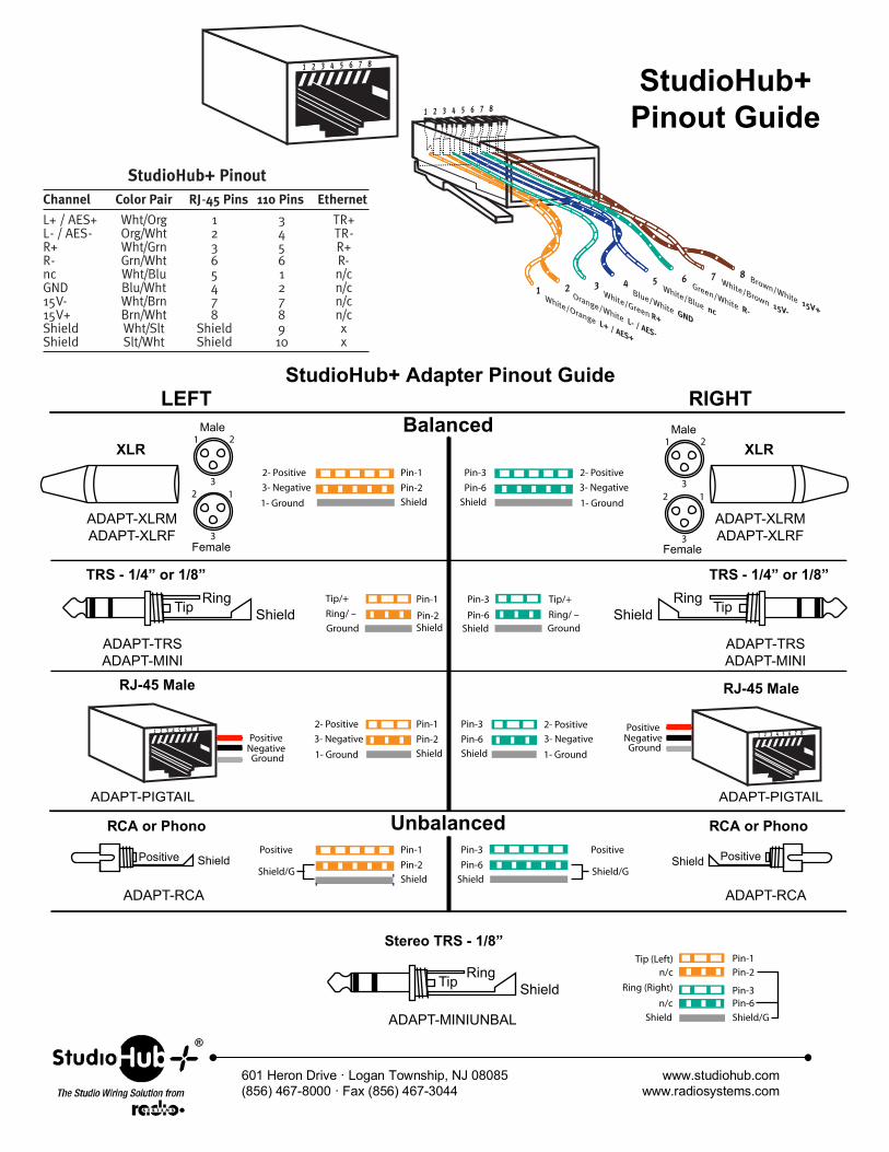
StudioHub+ Pinout Guide StudioHub+ Adapter Pinout Guide ® www.studiohub.com www.radiosystems.com 601 Heron Drive · Logan Township, NJ 08085 (856) 467-8000 · Fax (856) 467-3044 2- Positive Pin-1 Pin-2 Shield Pin-3 Pin-6 Shield 1 2 3 1 2 3 3- Negative Tip Male LEFT Balanced Unbalanced RIGHT Female Positive Shield Positive Shield Ring Shield Tip RJ-45 Male Ring Shield 1- Ground 1- Ground 2- Positive 1 2 3 1 2 3 3- Negative ADAPT-XLRM ADAPT-XLRF Male Female Pin-1 Pin-2 Shield Shield Pin-3 Pin-6 Shield/G Positive Tip/+ Pin-1 Pin-2 Shield Pin-3 Pin-6 Ring/ – Tip/+ Ring/ – Ground Positive Negative RJ-45 Male Ground Positive Negative 1- Ground 1- Ground Ground Shield Ground 2- Positive Pin-1 Pin-2 Pin-3 Pin-6 Shield Shield 3- Negative 2- Positive 3- Negative XLR ADAPT-XLRM ADAPT-XLRF XLR ADAPT-RCA RCA or Phono ADAPT-RCA RCA or Phono ADAPT-TRS ADAPT-MINI TRS - 1/4” or 1/8” ADAPT-TRS ADAPT-MINI ADAPT-PIGTAIL ADAPT-PIGTAIL TRS - 1/4” or 1/8” Pin-2 Pin-1 Pin-6 Shield/G ADAPT-MINIUNBAL Stereo TRS - 1/8” Shield/G Positive n/c Tip (Left) Shield n/c Pin-3 Ring (Right) Tip Ring Shield
Transcript of StudioHub+ Adapter Pinout Guidestudiohub.com/PDF/PinoutGuidewithAdapters.pdfPin-2 Pin-1 Pin-6...
StudioHub+Pinout Guide
StudioHub+ Adapter Pinout Guide
®
www.studiohub.comwww.radiosystems.com
601 Heron Drive · Logan Township, NJ 08085(856) 467-8000 · Fax (856) 467-3044
2- Positive Pin-1
Pin-2
Shield
Pin-3
Pin-6
Shield
1 2
312
3
3- Negative
Tip
Male
LEFTBalanced
Unbalanced
RIGHT
Female
Positive Shield PositiveShield
RingShield Tip
RJ-45 Male
RingShield
1- Ground1- Ground
2- Positive
1 2
312
3
3- Negative
ADAPT-XLRMADAPT-XLRF
Male
Female
Pin-1
Pin-2
Shield Shield
Pin-3
Pin-6Shield/G
Positive
Tip/+ Pin-1
Pin-2Shield
Pin-3
Pin-6Ring/ –
Tip/+
Ring/ –
Ground
PositiveNegative
RJ-45 Male
Ground
PositiveNegative
1- Ground 1- Ground
Ground Shield Ground
2- Positive Pin-1
Pin-2
Pin-3
Pin-6
ShieldShield
3- Negative
2- Positive
3- Negative
XLR
ADAPT-XLRMADAPT-XLRF
XLR
ADAPT-RCA
RCA or Phono
ADAPT-RCA
RCA or Phono
ADAPT-TRSADAPT-MINI
TRS - 1/4” or 1/8”
ADAPT-TRSADAPT-MINI
ADAPT-PIGTAIL ADAPT-PIGTAIL
TRS - 1/4” or 1/8”
Pin-2
Pin-1
Pin-6
Shield/GADAPT-MINIUNBAL
Stereo TRS - 1/8”
Shield/G
Positive
n/cTip (Left)
Shield
n/cPin-3Ring (Right)Tip Ring
Shield
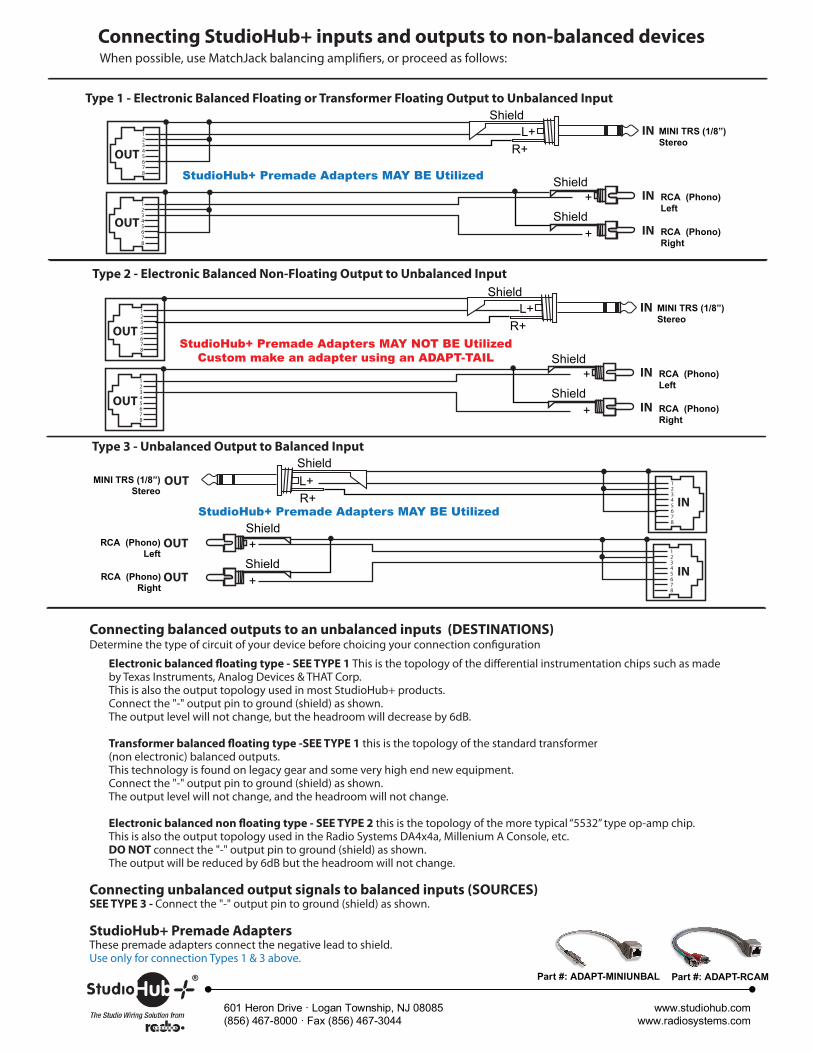
When possible, use MatchJack balancing ampli�ers, or proceed as follows:
Connecting unbalanced output signals to balanced inputs (SOURCES)SEE TYPE 3 - Connect the "-" output pin to ground (shield) as shown.
Connecting balanced outputs to an unbalanced inputs (DESTINATIONS)Determine the type of circuit of your device before choicing your connection con�guration
Electronic balanced �oating type - SEE TYPE 1 This is the topology of the di�erential instrumentation chips such as made by Texas Instruments, Analog Devices & THAT Corp.This is also the output topology used in most StudioHub+ products.Connect the "-" output pin to ground (shield) as shown. The output level will not change, but the headroom will decrease by 6dB.
Transformer balanced �oating type -SEE TYPE 1 this is the topology of the standard transformer (non electronic) balanced outputs.This technology is found on legacy gear and some very high end new equipment. Connect the "-" output pin to ground (shield) as shown. The output level will not change, and the headroom will not change.
Electronic balanced non �oating type - SEE TYPE 2 this is the topology of the more typical “5532” type op-amp chip.This is also the output topology used in the Radio Systems DA4x4a, Millenium A Console, etc. DO NOT connect the "-" output pin to ground (shield) as shown.The output will be reduced by 6dB but the headroom will not change.
Part #: ADAPT-MINIUNBAL Part #: ADAPT-RCAM
StudioHub+ Premade AdaptersThese premade adapters connect the negative lead to shield. Use only for connection Types 1 & 3 above.
Connecting StudioHub+ inputs and outputs to non-balanced devices
StudioHub+ Premade Adapters MAY BE Utilized
StudioHub+ Premade Adapters MAY BE Utilized
StudioHub+ Premade Adapters MAY NOT BE UtilizedCustom make an adapter using an ADAPT-TAIL
®
www.studiohub.comwww.radiosystems.com
601 Heron Drive · Logan Township, NJ 08085(856) 467-8000 · Fax (856) 467-3044
Type 1 - Electronic Balanced Floating or Transformer Floating Output to Unbalanced Input
Type 2 - Electronic Balanced Non-Floating Output to Unbalanced Input
Type 3 - Unbalanced Output to Balanced Input
Shield+
Shield+
RCA (Phono)Left
RCA (Phono)Right
12345678
IN
OUT
OUT
OUT
MINI TRS (1/8”)Stereo
L+R+
Shield12345678
IN
IN
IN
IN
MINI TRS (1/8”)Stereo
L+R+
Shield12345678
OUT
OUT
Shield+
Shield+
RCA (Phono)Left
RCA (Phono)Right
12345678
IN
IN
IN
MINI TRS (1/8”)Stereo
L+R+
Shield12345678
OUT
OUT
Shield+
Shield+
RCA (Phono)Left
RCA (Phono)Right
12345678
OUT
OUT


![Atmel | SMART SAM4N16 SAM4N8 Datasheet...SAM4N8/SAM4N16 [DATASHEET] Atmel-11158B-ATARM-SAM4N8-SAM4N16-Datasheet_23-Mar-15 8 4. Package and Pinout SAM4N devices are pin-to-pin compatible](https://static.fdocuments.in/doc/165x107/60dfbaec88785c6c186ab092/atmel-smart-sam4n16-sam4n8-datasheet-sam4n8sam4n16-datasheet-atmel-11158b-atarm-sam4n8-sam4n16-datasheet23-mar-15.jpg)

