Structure Design of Cargo Tanks in River Liquefied Gas ...
12
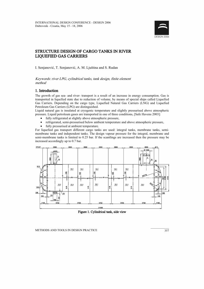
METHODS AND TOOLS IN DESIGN PRACTICE 357 INTERNATIONAL DESIGN CONFERENCE - DESIGN 2006 Dubrovnik - Croatia, May 15 - 18, 2006 STRUCTURE DESIGN OF CARGO TANKS IN RIVER LIQUEFIED GAS CARRIERS I. Senjanović, T. Senjanović, A. M. Ljuština and S. Rudan Keywords: river LPG, cylindrical tanks, tank design, finite element method 1. Introduction The growth of gas sea- and river- transport is a result of an increase in energy consumption. Gas is transported in liquefied state due to reduction of volume, by means of special ships called Liquefied Gas Carriers. Depending on the cargo type, Liquefied Natural Gas Carriers (LNG) and Liquefied Petroleum Gas Carriers (LPG) are distinguished. Liquid natural gas is insulated at cryogenic temperature and slightly pressurised above atmospheric pressure. Liquid petroleum gases are transported in one of three conditions, [Safe Havens 2003]: • fully refrigerated at slightly above atmospheric pressure, • refrigerated, semi-pressurised below ambient temperature and above atmospheric pressure, • fully pressurised at ambient temperature. For liquefied gas transport different cargo tanks are used: integral tanks, membrane tanks, semi- membrane tanks and independent tanks. The design vapour pressure for the integral, membrane and semi-membrane tanks is limited to 0.25 bar. If the scantlings are increased then the pressure may be increased accordingly up to 0.7 bar. Figure 1. Cylindrical tank, side view
Transcript of Structure Design of Cargo Tanks in River Liquefied Gas ...
METHODS AND TOOLS IN DESIGN PRACTICE 357
INTERNATIONAL DESIGN CONFERENCE - DESIGN 2006 Dubrovnik - Croatia, May 15 - 18, 2006
STRUCTURE DESIGN OF CARGO TANKS IN RIVER LIQUEFIED GAS CARRIERS
I. Senjanović, T. Senjanović, A. M. Ljuština and S. Rudan
Keywords: river LPG, cylindrical tanks, tank design, finite element method
1. Introduction The growth of gas sea- and river- transport is a result of an increase in energy consumption. Gas is transported in liquefied state due to reduction of volume, by means of special ships called Liquefied Gas Carriers. Depending on the cargo type, Liquefied Natural Gas Carriers (LNG) and Liquefied Petroleum Gas Carriers (LPG) are distinguished. Liquid natural gas is insulated at cryogenic temperature and slightly pressurised above atmospheric pressure. Liquid petroleum gases are transported in one of three conditions, [Safe Havens 2003]:
• fully refrigerated at slightly above atmospheric pressure, • refrigerated, semi-pressurised below ambient temperature and above atmospheric pressure, • fully pressurised at ambient temperature.
For liquefied gas transport different cargo tanks are used: integral tanks, membrane tanks, semi-membrane tanks and independent tanks. The design vapour pressure for the integral, membrane and semi-membrane tanks is limited to 0.25 bar. If the scantlings are increased then the pressure may be increased accordingly up to 0.7 bar.
Figure 1. Cylindrical tank, side view

METHODS AND TOOLS IN DESIGN PRACTICE 358
Independent cargo tanks are self-supported structures and do not participate in the ship's strength. They are further subdivided into A, B and C type. The first two tank categories are usually plane structures and the design vapour pressure is up to 0.7 bar. The type C independent tanks are shell structures meeting the vessel criteria. They operate up to the design vapour pressure of 20 bar. Since the transport of gas is hazardous due to potential danger as fire, toxicity, corrosiveness, reactivity, low temperature and high pressure, it is regulated by the International Code for Construction and Equipment of Ships Carrying Liquefied Gases in Bulk (IGC Code) [Resolution MSC.5(48) 1993, Böckenhauer 1981]. The Unified Requirements G1 and G2 of the IGC Code are specified by the International Association of Classification Societies (IACS), and each of IACS members has incorporated this document into their own classification rules, [Rules GL 2000]. This paper deals with the methodology of structure design of the type C independent cargo tanks, also referred to as pressure vessels, built in river ships. The design of tanks for river ships is much easier than for the seagoing ships. Only the design vapour pressure without liquid pressure caused by ship's motion in waves is taken into account. Thus, swash bulkheads are not required for tanks in river ships. The tank supports have to be designed to withstand longitudinal acceleration of 0.3 g in case of collision. The volume of one tank is limited to 380 m3.
2. Tank particulars The design procedure is illustrated in case of a river ship which is equipped with eight cylindrical tanks in two rows. The tanks particulars are the following, Figs. 1 and 2:
outer diameter 4730 mm total length 21 000 mm design pressure 15.8 bar test pressure 237 bar max. outer overpressure 0.6 bar (vacuum) temperature –10°C up to +40°C material S 690 QL1
Essential equipment reads: one manhole, diameter 700 mm one dome for gauge, diameter 500 mm one valve dome, diameter 1200 mm one nozzle for deep well pump, diameter 600 mm one sump for deep well pump, diameter 700 mm ten nozzles, diameter 50 – 125 mm three thermowells, four sample-lines inside upper spray line, diameter 100 mm inside lower spray line, diameter 125 mm ladder
The tanks are covered with epoxy coating of 300 micron. The tanks are designed according to the Rules of Germanischer Lloyd (GL) and the rules for the transport of dangerous goods on the river Rhine (ADNR). The applicable GL Rules are [Rules GL 2000]:
• Pressure Vessels for Inland Waterway Vessels, (general requirements), • Steam Boilers (calculation formulae applicable to pressure vessels), • Materials (steel for cargo tanks), • Welding of pressure vessels.
ADNR Rules are written in French and German. However, the ADNR technical rules, Part 9, are nearly identical to the ADN technical rules, Part 9. The ADN are the recommendations for the transport of dangerous goods on inland waterways from the United Nations Economic Commission for Europe [Recommendations...].

METHODS AND TOOLS IN DESIGN PRACTICE 359
Figure 2. Cylindrical tank, top view
Material for tank production is S 690 QL1 with the following characteristics: Young's modulus, E = 2.06 · 105 N/mm2 Poisson's ratio, υ = 0.3 yield stress, Re = 690 N/mm2 tensile strength, Rm = 770 N/mm2
The allowable stress according to GL yields: allowable membrane stress, amσ = Rm /2.7 = 285 N/mm2 allowable total stress, atσ = 0.57 Rm = 439 N/mm2
3. Shell thickness The cargo tanks structure consists of cylindrical shells and spherical dished ends with a toroidal connection for the reduction of stress concentration. In a similar way, the tank domes and sumps are constructed. Thickness of the constitutive shell types is determined by using the GL Rules formulae for pressure vessel and steam boilers, which are based on the membrane theory and allowable stresses, as given below [Rules GL 2000].
Cylindrical shell Spherical shell Toroidal shell
cam
ca
pvpDt+
=σ20
cam
ca
pvpDt+
=σ40
v
pDtam
ca
σβ
40=
where: t - thickness, mm Da - outside diameter, mm pc - design pressure, bar β - design coefficient for dished ends v - weakening factor
amσ - allowable membrane stress

METHODS AND TOOLS IN DESIGN PRACTICE 360
Figure 3. Head of cylindrical tank
In the considered case the value of the outer diameter of the cylindrical and toroidal shell reads Da = 4 730 mm, while diameter of the spherical shell is Da = 7 580 mm. Furthermore, the value of the weakening factor v = 1 is taken into account. Based on the above data, the thickness of the cylindrical and spherical shells yields 13.1 mm and 10.5 mm respectively, Fig. 3. The value of the design coefficient β = 2.45 for the toroidal shell is determined from the corresponding diagram in [Rules GL 2000] based on the ratio H / Da and t / Da, where H is the height of dished ends. The thickness of the dome and sump is determined in a similar way according to the GL Rules and AD Merkblatt [AD Merkblatt 1990]. The weakening effect in the tank shell due to the dome and sump existence is calculated by taking into account the compensation for the open areas. The tank shell is shown in Figures 1, 2 and 3.
4. Shell Buckling
4.1 Cylindrical shell In the case of external pressure a segment of the cylindrical tank shell between the two vacuum rings may lose stability. According to the GL Rules the critical pressure for elastic buckling of a cylindrical shell is determined by the following formula [Rules GL 2000]:
⎪⎪⎪
⎭
⎪⎪⎪
⎬
⎫
⎪⎪⎪
⎩
⎪⎪⎪
⎨
⎧
⎥⎥⎥⎥
⎦
⎤
⎢⎢⎢⎢
⎣
⎡
⎟⎠⎞
⎜⎝⎛+
−−+−−
⎟⎟⎠
⎞⎜⎜⎝
⎛ −
+
⎥⎥⎦
⎤
⎢⎢⎣
⎡⎟⎠⎞
⎜⎝⎛+−
−
= 2
22
2
3
222 1
121)1(3
1)1(
20
zn
nnD
ct
znn
Dct
SEp aa
k
tcr
υυ
(1)
where

METHODS AND TOOLS IN DESIGN PRACTICE 361
2,002.03,2 ak
a DR
Rct
Sl
Dz =−
+==π
(2)
and further pcr - critical pressure, bar t - shell thickness, mm Da - outside diameter, mm l - length of shell, mm c - allowance for corrosion and wear, mm Et - modulus of elasticity at design temperature, N/mm2 υ - Poisson's ratio Sk - safety factor against elastic buckling n - number of buckled folds occurring round the periphery in the event of failure, which gives
minimum pcr value.
0
1
2
3
4
5
6
7
8
9
10
0 2 4 6 8 10 12 14 16 18 20 22 24 26
n
p (b
ar)
Figure 4. Critical pressure of cylindrical segment
In the considered case l = 3 722 mm and c = 0 so that z = 1.995 and Sk = 3.36. By varying the number of buckled folds n in (1) value of critical pressure is determined as shown in Figure 4. The minimum pressure value pcr = 0.856 bar is obtained for n = 8, that is higher than the given external value pe = 0.6 bar. Therefore, the cylindrical shell reinforced by the vacuum rings at distance l = 3 722 mm is stable.
4.2 Spherical shell The tank dished ends are designed as segments of the spherical shell. Their stability may be checked by determining the buckling pressure of the complete sphere. According to the GL Rules, buckling pressure is given by the formula [Rules GL 2000]:
2
66.3 ⎟⎠⎞
⎜⎝⎛ −=
Rct
SEp
k
tcr (3)
Since Sk = 3.72 one finds pcr = 1.565 bar that is higher than the external pressure pe = 0.6 bar. Thus, the spherical shell is stable.

METHODS AND TOOLS IN DESIGN PRACTICE 362
5. Vacuum rings The vacuum rings are used to ensure the stability of the tank shell in the event of the internal pressure being reduced below the atmospheric value. The design pressure difference, called external pressure, is pe = 0.6 bar.
Figure 5. Vacuum ring
The vacuum ring is shown in Figure 5. Its cross-section 145 × 25 mm, together with the effective breadth of the cylindrical shell
27456.1 == tRbm mm (4)
forms a T–profile with the moment of inertia I = 0.168 · 10-4 m4. The span between the vacuum rings, l = 3 722 mm, is determined in the buckling analysis of the cylindrical shell. Critical pressure of a ring is given by formula [Handbook of Structural Stability 1971]:
lREIpcr 3
3= (5)
Thus, one finds pcr = 2.15 bar, so that the safety factor takes an acceptable value S = pcr / pe =3.58.
6. Stiffening rings
6.1 Ring load Steel mass is approximately 34.4 t. Tank volume is 351.4 m3 and in case of transport of vinyl chloride monomer, where mass density is ρ = 0.97 t/m3, the cargo mass reads 341 t. Thus, the total tank weight takes the value of 3 682 kN. The tank support is loaded by one half of that amount, i.e. Q = 1 841 kN. The stiffening ring is exposed to the action of circumferential shear load due to tank bending as a thin

METHODS AND TOOLS IN DESIGN PRACTICE 363
wall structure between two supports. Thus, the shear distribution is presented with the formula, Figure 6a
πϕϕ 20,sin0
≤≤= tt qq (6)
where 0tq is obtained from equilibrium condition of vertical forces
∫=π
ϕϕ0
sin2 dRqQ t (7)
By substituting (6) into (7) one finds
2480
==πR
Qqt kN/m (8)
On the other side, the reaction of the saddle support is distributed as shown in Figure 6b, i.e.
πϕπϕ23
2,cos
0≤≤= ss qq (9)
where based on the equilibrium condition of vertical forces
∫=π
π
ϕϕ2
dRqQ s cos2 (10)
Thus, by substituting (9) into (10) yields
πRQqs
20
= (11)
Figure 6. Load of stiffening ring: a – shear load, b – reaction load

METHODS AND TOOLS IN DESIGN PRACTICE 364
Figure 7. Deformation of stiffening ring
(the bottom point is fixed)
Figure 8. Axial force of stiffening ring Nxx,
(maximum value at the ring bottom, =ϕ 180°)

METHODS AND TOOLS IN DESIGN PRACTICE 365
Figure 9. Shear force of stiffening ring Nxz,
(extreme values in the points =ϕ 45°, 135°, 225° and 315°)
Figure 10. Bending moment of stiffening ring My,
(extreme values in the points =ϕ 0°, 90°, 180° and 270°)

METHODS AND TOOLS IN DESIGN PRACTICE 366
6.2 Ring forces The ring sectional forces due to the relative circumferential shear load and normal support reaction, i.e. taking Q = 1 kN into account, are determined by the finite element method, using the program [SESAM 1999]. The T–profile of the ring cross-section is assumed as follows: effective breadth of the cylindrical shell
27456.1 == cm Rtb mm
web 500 × 20 and flange 300 × 25 mm. Thus, the resulting cross-section parameters are:
• cross-section area, A = 0.021 m2 • shear area, Aw = 0.01 m2 • moment of inertia, I = 0.919 · 10-3 m4.
The ring circumference is divided into 72 arch elements by step of the central angle of 5°, starting from the ring top. The rigid body motion of the ring model is suspended. The obtained results of the FEM analysis are shown in Figures 7, 8, 9 and 10. The actual sectional forces for each stiffening ring are obtained by multiplying their relative values calculated for the unit tank shear force with the corresponding value of the support reaction.
6.3 Ring stresses The stresses caused by the actual sectional forces are calculated at five positions of the ring cross-section in two Gaussian points of each arch element of the ring FEM model. The stress positions are chosen in the symmetry line of the cross-section, at the level of neutral axis, at the ends of the web and at the outer side of the flange and tank shell, Figure 11. Furthermore, the equivalent stresses at the same positions and points are determined using the von Mises formula
bnx
xyyxyxe
σσσ
τσσσσσ
+=
+−+= 222 3 (12)
Figure 11. Cross-section of stiffening ring

METHODS AND TOOLS IN DESIGN PRACTICE 367
where xσ and yσ are normal stresses in the x and y direction respectively, xyτ is shear stress in the
xy plane, nσ and bσ are normal stresses due to the axial force and the bending moment respectively. The final dimensions of the stiffening rings at different cross-sections are determined by varying the initial scantlings until meeting the stress criteria. Based on the difference between the equivalent and allowable stresses, the flange and web thickness and the web height are changed.
Figure 12. Stiffening ring
The final scantlings of the ring are shown in Figure 12. The web is reinforced with bars against buckling. Distribution of the equivalent von Mises stress at five points of the ring cross-section is presented in Figure 13. Clockwise numbering of the arch finite elements starts from the tank top. Maximum stress occurs in the cylindrical shell at the ring bottom very close to the allowable value
=atσ 439 N/mm2.
7. Conclusion Liquefied Gas Carriers are special and sophisticated ships. Due to high pressure and low temperature, the design of their cargo tanks requires special attention [Senjanović et al. 2002]. Therefore, the Classification Rules are the implementation of the IMO Code requirements. The design of cargo tanks in river ships is somewhat simpler than that for sea going ships since hydrodynamic load due to ship motion in waves is not actual. Only longitudinal acceleration of 0.3 g in case of ship collision is taken into account for the design of tank supports. This paper deals with the design methodology and procedure of the C type cargo tanks in river ships. The integral procedure includes the way of
• determination of shell thickness according to the Classification Rules, • checking of stability of structural elements (cylindrical and spherical shells and vacuum rings)
according to the buckling theory, • scantlings of stiffening rings based on the theory of thin-walled girders.
The procedure may be used as a design standard since it is in accordance with the requirements of Classification Societies. The presented example of tank design illustrates the application of the procedure that may be useful in design of similar tanks. Besides the challenge of the tank design, some problems during tank manufacturing may be of special interest as for instance the remedy of tank misalignment, [Senjanović et al. 2005].

METHODS AND TOOLS IN DESIGN PRACTICE 368
Figure 13. Von Mises stresses in stiffening ring
References AD Merkblatt B3, Edition 10.90, 1990. Böckenhauer, M., "Some notes on the practical application of the IMCO Gas Carrier Code to pressure vessel type cargo tanks", Proceedings of conference with Exhibition, GASTECH, 1981. Handbook of Structural Stability, Edited by Column Research Committee of Japan, Corona Publishing Company, Ltd. Tokyo, 1971. Recommendations for the transport of dangerous goods on inland waterways, The United Nations Economic commission for Europe, http://www.unece.org/trans/danger/adnry2005.html. Resolution MSC.5(48) International Code for the Construction and Equipment of Ships Carrying Liquefied Gasses in Bulk, IMO, Edition 1993. Rules for Classification and construction, I ship Technology, 1 Seagoing Ships, 6 Liquefied Gas Tankers, Germanischer Lloyd, 2000. Safe Havens for Disabled Gas Carriers, Society of International Gas Tanker & Terminal Operations Ltd., third Edition, February, 2003. Senjanović, I., Mravak, Z., Slapničar, V., Gospić, I., "Structure design of bilobe cargo tanks in Liquefied Gas Carriers", Brodogradnja, 50 (2002) 3, pp. 323-334. Senjanović, I., Rudan, S., Ljuština A.M., "Reinforcement of imperfect bilobe cargo tanks in Liquefied Gas Carriers", Brodogradnja, 55 (2005) 2, pp. 123-140. "SESAM User's manual", Det norske Veritas, Hövik, 1999. Ivo Senjanović, Professor University of Zagreb, Faculty of Mechanical Engineering and Naval Architecture, Ivana Lučića 5, 10000 Zagreb, Croatia Tel.: +385 1 6168-164 Fax.: +385 1 6156-940 Email: [email protected]