Structurally Integrated Antenna Concepts for HALE UAVs · PDF fileStructurally Integrated...
23
October 2006 NASA/TM-2006-214513 Structurally Integrated Antenna Concepts for HALE UAVs Robin L. Cravey, Erik Vedeler, Larry Goins, W. Robert Young, and Roland W. Lawrence Langley Research Center, Hampton, Virginia https://ntrs.nasa.gov/search.jsp?R=20060051786 2018-05-21T08:17:50+00:00Z
Transcript of Structurally Integrated Antenna Concepts for HALE UAVs · PDF fileStructurally Integrated...

October 2006
NASA/TM-2006-214513
Structurally Integrated Antenna Concepts for HALE UAVs Robin L. Cravey, Erik Vedeler, Larry Goins, W. Robert Young, and Roland W. Lawrence Langley Research Center, Hampton, Virginia
https://ntrs.nasa.gov/search.jsp?R=20060051786 2018-05-21T08:17:50+00:00Z

The NASA STI Program Office . . . in Profile
Since its founding, NASA has been dedicated to the advancement of aeronautics and space science. The NASA Scientific and Technical Information (STI) Program Office plays a key part in helping NASA maintain this important role.
The NASA STI Program Office is operated by Langley Research Center, the lead center for NASA’s scientific and technical information. The NASA STI Program Office provides access to the NASA STI Database, the largest collection of aeronautical and space science STI in the world. The Program Office is also NASA’s institutional mechanism for disseminating the results of its research and development activities. These results are published by NASA in the NASA STI Report Series, which includes the following report types:
• TECHNICAL PUBLICATION. Reports of
completed research or a major significant phase of research that present the results of NASA programs and include extensive data or theoretical analysis. Includes compilations of significant scientific and technical data and information deemed to be of continuing reference value. NASA counterpart of peer-reviewed formal professional papers, but having less stringent limitations on manuscript length and extent of graphic presentations.
• TECHNICAL MEMORANDUM. Scientific
and technical findings that are preliminary or of specialized interest, e.g., quick release reports, working papers, and bibliographies that contain minimal annotation. Does not contain extensive analysis.
• CONTRACTOR REPORT. Scientific and
technical findings by NASA-sponsored contractors and grantees.
• CONFERENCE PUBLICATION. Collected
papers from scientific and technical conferences, symposia, seminars, or other meetings sponsored or co-sponsored by NASA.
• SPECIAL PUBLICATION. Scientific,
technical, or historical information from NASA programs, projects, and missions, often concerned with subjects having substantial public interest.
• TECHNICAL TRANSLATION. English-
language translations of foreign scientific and technical material pertinent to NASA’s mission.
Specialized services that complement the STI Program Office’s diverse offerings include creating custom thesauri, building customized databases, organizing and publishing research results ... even providing videos. For more information about the NASA STI Program Office, see the following: • Access the NASA STI Program Home Page at
http://www.sti.nasa.gov • E-mail your question via the Internet to
[email protected] • Fax your question to the NASA STI Help Desk
at (301) 621-0134 • Phone the NASA STI Help Desk at
(301) 621-0390 • Write to:
NASA STI Help Desk NASA Center for AeroSpace Information 7121 Standard Drive Hanover, MD 21076-1320

National Aeronautics and Space Administration Langley Research Center Hampton, Virginia 23681-2199
October 2006
NASA/TM-2006-214513
Structurally Integrated Antenna Concepts for HALE UAVs Robin L. Cravey, Erik Vedeler, Larry Goins, W. Robert Young, and Roland W. Lawrence Langley Research Center, Hampton, Virginia

Available from: NASA Center for AeroSpace Information (CASI) National Technical Information Service (NTIS) 7121 Standard Drive 5285 Port Royal Road Hanover, MD 21076-1320 Springfield, VA 22161-2171 (301) 621-0390 (703) 605-6000
Acknowledgments
The authors would like to acknowledge Hunter Walden, Eddie Ford, and Theresa Butler for their measurement and modeling support on this project.
The use of trademarks or names of manufacturers in the report is for accurate reporting and does not constitute an official endorsement, either expressed or implied, of such products or manufacturers by the National Aeronautics and Space Administration.

1
Introduction
This technical memorandum describes work done in support of the Multifunctional Structuresand Materials Team under the Vehicle Systems Program’s ITAS (Integrated Tailored AeroStructures) Project during FY 2005. The Electromagnetics and Sensors Branch (ESB) developedthree ultra lightweight antenna concepts compatible with HALE UAVs (High Altitude LongEndurance Unmanned Aerial Vehicles). ESB also developed antenna elements that minimize theinteraction between elements and the vehicle to minimize the impact of wing flexure on the EM(electromagnetic) performance of the integrated array. In addition, computer models weredeveloped to perform phase correction for antenna arrays whose elements are moving relative toeach other due to wing deformations expected in HALE vehicle concepts. Development oflightweight, conformal or structurally integrated antenna elements and compensating for theimpact of a lightweight, flexible structure on a large antenna array are important steps in therealization of HALE UAVs for microwave applications such as passive remote sensing andcommunications.
Background
In recent years there has been rapidly increasing interest in Unmanned Aerial Vehicles (UAVs),also called Remotely Piloted Vehicles (RPVs), for numerous applications. These UAVapplications compare extremely favorably to current technology alternatives such as spacebornesatellites, lighter than air, and piloted aircraft. The interest, mission goals and availabletechnology developed in the last several years have spawned many mission specificsubcategories of UAVs. The world has seen the high profile effectiveness of military UAVs,such as Predator®, a registered trademark of General Atomics Aeronautical Systems Inc., andGlobalhawk®, a registered trademark of Northrop Grumman Corp., capable of deliveringweapons to, and intelligence from, threat regions. Since the mid 1990s, however, there has beena rapidly growing niche for High Altitude Platform Stations (HAPS) and the use of UAVs tosupport such missions. NASA has been involved with HAPS concepts in the EnvironmentalResearch Aircraft and Sensor Technology (ERAST), HALE programs and of course the recordbreaking Helios Prototype (see Figure 1).

2
Figure 1. Helios prototype test flight.
After several generations of HAPS – UAVs starting back in 1997 with the Pathfinder, the HeliosPrototype in August 2001 exceeded the altitude record for fixed wing jet or propeller aircraft byreaching 96,000 ft. Being solar powered and above weather systems the plane could remain ataltitude indefinitely during daylight hours. Currently research is being conducted at NASA andelsewhere to develop lightweight electrical energy storage devices such as hydrogen fuel cellsand lightweight batteries to extend the capability to stay aloft through the nighttime hours. Theimpact of a success would be far reaching, and future mission goals of HAPS would be tomaintain the UAV at 60,000 ft for up to 6 months. No piloted aircraft could perform such amission.
Potential mission areas for microwave HAPS-UAVs
This section identifies three broad areas where appropriately designed microwave HAPS-UAVscould have huge impacts in the immediate future. The mission areas are environmental,communications and military.
Environmental – Microwave passive remote sensing instruments are vital to understandingnumerous ecological, meteorological / climatological and agricultural phenomena.

3
Communications – broadband wireless technology is today currently limited by the ability todeliver the high capacity data and other information to potential users. Examples of thesecurrent needs are in 3G mobile, direct broadcast (radio, TV, HDTV), fixed and mobilebroadband (internet) and high capacity narrowband (mobile voice).
Military – Ground Penetrating Radar (GPR), Foliage Penetrating Radar (FPR), SyntheticAperture Radar (SAR), C3 (Command, Control and Communications) / Airborne Warning andControl Systems (AWACS).
The GPR technology also has many commercial / research uses such as environmental andarcheological.
The above applications all have one important thing in common. They all rely heavily on theUHF / L-Band microwave frequency range.
Antennas for microwave HAPS-UAV applications
To achieve the desired performance characteristics for HALE UAVs, the overall vehicle weightmust be minimized. When designing the various subsystems which must be included on thevehicle, one approach is to attempt to reduce the weight and aerodynamic impact of eachsubsystem independently. A more holistic approach is to combine functionality between thevehicle structure and various subsystems in order to eliminate unnecessary components and thusreduce weight. This approach is particularly beneficial for applications where long wavelengthsand high spatial resolution are required. Since required antenna apertures can be very vehicleintrusive, optimizing the sensor/vehicle concept to meet the mission requirements may lead tosubstantially improved performance
In support of the Multifunctional Structures and Materials Team under the Vehicle SystemsProgram’s ITAS Project, ESB developed several antenna concepts integrable with HALE UAVvehicle configurations. The antennas were designed to be either very lightweight and thin (thefirst approach described above) or to have part of the vehicle structure providing either physicalsupport for the antennas, electromagnetic functionality, or both (the second approach describedabove).
The frequency ranges required for HALE UAV antennas will vary according to the specificapplication. The biggest challenge, however, will be the design of antennas for the lowerfrequencies. Higher frequency antennas are inherently smaller and would have less impact onthe overall vehicle weight. In some cases (L-band soil moisture measurements, for example) theantenna array might need to span the entire vehicle. Unless the weight of the elements iscarefully considered during the design, including such an array on a HALE UAV might beimpossible.

4
In addition to the weight issue, another aspect of HALE UAVs must be considered if they are tosupport missions which require large antenna arrays with elements which are distributed over theentire vehicle. The flexibility of such a large, lightweight structure will induce errors in theantenna array pattern as the elements move relative to each other when the vehicle aeroelasticallyflexes during flight. For some applications, the errors in the array pattern will causeunacceptable errors in the data. Some correction technique must be used to mitigate the effectsof the vehicle flexion.
In the following sections, three antenna designs are described which have potential for use onHALE UAVs. In addition to being lightweight, two of the designs are envisioned as structurallyintegrated antennas, and one is envisioned as a very thin conformal surface mounted element.Following the discussion of the antenna elements developed for the program, a description of acomputational phase correction technique to mitigate the effects of vehicle distortion on a largeantenna array is given. Such a correction scheme will be necessary for passive remote sensingapplications using large, flexible antenna arrays such as the one envisioned here.
Design assumptions
The goal of this work is to develop antennas which are compatible with a HALE UAV platform.The approach taken was to address the most challenging technology development issues. Also, itwas desired to develop specific antennas which could be modeled, fabricated and tested. Certaindesign assumptions about the frequencies of interest and the HALE UAV vehicle configurationwere made a priori to achieve these goals. This section describes these assumptions.
Frequency: As explained in the previous section, the lowest frequencies of interest are seen asthe biggest challenge for the HALE UAV antenna design, due to the physical size requirementsfor these frequencies. For this reason, this research concentrated on UHF / L-Band frequencies.Interest in UHF / L-Band frequencies for many applications is due to a number of reasons. Forcommunications, low frequency RF has the unique ability to penetrate and “bend” aroundbuildings’ topography. UHF and L-Band are at the upper end of what would be considered lowband, and to gain the maximum bandwidth for data capacity this is the obvious choice. The FCChas designated a number of frequency bands in this range for mobile telephone and othercommunication uses. Sometimes the frequency is dictated by physics as in the case ofradiometry, GPR and FPR. L-Band happens to contain a strong water emission line.
Vehicle configuration: This section explains some of the rationale for the UAV configurationchosen for this study. The UAV as outlined in this paper is designed to fly at extraordinarilyhigh altitudes for great lengths of time. Because of this the high altitude, extremely high lift andlow velocity requirements of the mission, AeroVironment Inc. and other air framers have notonly considered but also built actual prototypes of flying wings. The flying wings have beeneither of single wing element or bi-plane design. The bi-plane design was primarily considered

5
for structural reasons, but it was the single wing element design which was actually used in theHelios and Pathfinder missions. Since there is no fuselage on these candidate aircraft we haveconsidered only wing surface and some potential wing volumes as possible locations forantennas.
Figure 2 shows the vehicle and a potential wing cross section design. This cross section is basedon a few assumptions made following structural and onboard power needs discussions. As canbe seen there is a forward and rear span-wise structural member assumed to run along the length(span) of the wing. With the possibility of a hydrogen fuel cell electrical power storage system,it has been envisioned that the hydrogen would be stored in a metallized bladder (tank) betweenthese 2 structures. This tank may itself be this structure. The metallization creates antennaground plane possibilities for the antennas described in the following sections, as well as otherpotential designs. Chord-wise structural elements and a thin volume between the lower surfaceand the tank create ideal locations for the Vivaldi and reduced surface wave (RSW) antennasdescribed in detail in the following sections.
Figure 2. Potential antenna locations on HALE UAV wing section.
The leading edge has been identified as a potential free zone for antenna elements also. Therewould unlikely be any flight control surface or flight system requirements for this volume andwould be coveted by the antenna community. This volume is perfect for helical antennasdescribed in the next section. If appropriately designed, these antennas could potentially serve as

6
structural elements themselves. The size of this volume as indicated by the structural designswould be compatible with helical antennas from UHF to microwave frequencies.
Antenna designs
Helical antenna
The first antenna concept developed under this program is an extremely lightweight helicalantenna operating in the axial mode. A working one third scale model of the proposed helixantenna is described here. At one third scale, the actual working L band frequency of 900 MHzscales to 2.7 GHz. As can be seen in Figure 2, the concept for incorporating this antenna into aUAV wing involves using the forward spar as a ground plane, and it is envisioned that theleading edge of the wing would be filled with a lightweight, low dielectric constant foammaterial which would support the helix and also provide some structural stiffness for the wing.
The design goals for this antenna, in addition to light weight, were to have the broadest possiblebandwidth and beam width of 60 degrees. This helical design was accomplished using thefollowing guidelines for optimal performance:
The circumference of the helix (C) must be equal to a wavelength (λ)The number of turns (N) must be greater than 3 (4 were used in this case)The total length of the helix (L) must be equal to (λ/4) * N
From these guidelines, the following design parameters were obtained:
D = 3.56 cm = helix diameterL = N*(λ/4) = λ = 11.0 cmS = 2.75 cm = spacing between turns
From Equations 1 and 2 (Reference 1) we can compute the predicted axial ratio and half powerbeamwidth of the helical antenna.
Axial Ratio= (2*N+1)/2*N=1.125 (1)
Half Power Beamwidth=52 / (C/λ) * (N*S/λ)^(0.5) = 60 degrees (2)
As stated above, the antenna’s center frequency of 2.7 GHz scales to 900 MHz, the centerfrequency for the full size antenna. It is constructed on a 3.56 cm diameter polystyrene foamcylinder, which provides mechanical support. Four turns of 0.00254 cm thick copper tape 0.305cm wide were helically wound on the surface of the cylinder. The center to center spacing of thetape on the cylinder is 2.75cm. The tape was wound in a counter clockwise direction, as viewedfrom the top, and produces right hand circularly polarized radiation. The foam cylinder was

7
mounted in the center of a 30.5 cm (2.77 λ) square aluminum ground plane. The helix is fedusing an SMA connector mounted in the ground plane and has the center conductor connected tothe bottom of the helix at the level of the ground plane. In order to improve the impedancematch, it was necessary to add a small triangle of copper tape near the feed point of the helix atthe ground plane. The shape and location were empirically determined. The final antenna ispictured in Figure 3.
Figure 3. Foam and tape helical antenna
The antenna’s performance characteristics were measured in LaRC’s Low Frequency AntennaChamber. Test results exceeded the requirements envisioned, and are summarized in Table 1below:
Parameter Measured ValueBandwidth 1.9 to 3.5 GHzGain (circularly polarized) 8 dBi at band edges, 9 dBi at the centerBeamwidth 60 degreesAxial Ratio On axis band center: 0.5 dB
30 degrees off axis band center: 3.0dB30 degrees off axis band edge: 6.0 dB
S11 -10 dB or better across the bandWeight excluding ground plane andconnector
3.8 grams
Table 1. Foam and tape helical antenna performance summary.

8
A representative S11 plot and endfire pattern at the band center of 2.7 GHz are shown in Figure4. The input impedance for the helical antenna is seen to correspond to an S11 of less than -10dB from 2 to 3.5 GHz.
Copper Tape on Foam Helix Antenna
-18
-16
-14
-12
-10
-8
-6
-4
-2
0
1.5 2 2.5 3 3.5 4
Frequency in GHz
S1
1 in
dB
Figure 4. S11 and endfire pattern for foam and tape helical antenna.
For comparison purposes a free standing helical antenna had been constructed. This version wasmade using 10 gauge copper wire and has the same dimensions and ground plane size as thefoam version. This antenna is pictured in Figure 5. Performance characteristics werecomparable to the foam and tape helix.

9
Figure 5. Free standing helical antenna.
Vivaldi antenna
The second antenna concept proposed for HALE UAVs is a balanced antipodal Vivaldi (BAV)antenna. Vivaldi antennas are inherently very broadband and therefore could be potentiallyuseful for a wide range of applications. BAV antennas avoid some of the disadvantages ofregular Vivaldi antennas (high cross polarization, complicated feeding structure) by providing asimple stripline input and low cross polarization (Reference 2). A BAV antenna consists of twodielectric layers sandwiched with three metallic layers. The top and bottom metallic layers areidentical. They form the left side of the radiating element and the ground planes for the striplineinput (shown in gray in Figure 6). The middle metallic layer forms the right side of the radiatingelement and the strip for the stripline (shown in darker blue in Figure 6). The dielectric materialis shown in lighter blue in Figure 6.
Figure 6. MWS model of BAV antenna.

10
In Figure 2 was shown an artist’s concept of how the BAV antenna might be incorporated into aUAV’s wing strut. In order to realize a design like this in practice, antenna designers andstructural engineers would have to work closely in choosing materials which met both structuraland electromagnetic requirements.
To design a BAV which operates down to the desired L-band frequency range, a commercialelectromagnetics software modeling tool called CST-Microwave Studio was used. Acommercially available thin, lightweight, copper clad foam material called Foamclad R/F 100,manufactured by Arlon, was investigated as a potential material for use in this application. Thespecific material used in the design is 1.8796 mm thick, clad on both sides, and has a relativedielectric constant of 1.23. For an antenna size of 92 mm by 207 mm, Microwave Studio givesthe input impedance plot shown in Figure 7. The design has an acceptable S11 of approximately-8 dB or lower above about 1.5 GHz. By scaling the design slightly larger, acceptableperformance at lower frequencies could be obtained. Figure 7 also shows antenna patterns at 2and 3 GHz. The pattern cut is in the plane of the antenna, with the phi component having the Evector in the plane of the cut and the theta component having the E vector perpendicular to theplane of the cut.
Foamclad Vivaldi at 2 and 3 GHz
-50
-40
-30
-20
-10
0
10
0 30 60 90 120 150 180Theta (deg.)
Abs
olut
e ga
in (d
Bi)
Dir.Th[dBi] 2 GHzDir.Ph[dBi] 2 GHzDir.Th[dBi] 3 GHzDir.Ph[dBi] 3 Ghz
Foamclad Balanced Antipodal Vivaldi Computed S11
-20
-15
-10
-5
0
0 1 2 3 4
Frequency (GHz)
Mag
(S11
) (dB
)
Figure 7. Computed S11 and patterns for Foamclad R/F 100 BAV.

11
Reduced surface wave antenna
As discussed earlier in this paper, one important application for large, lightweight UAVs ispassive remote sensing of the earth. A concept which has been investigated in the past for thisapplication utilizes array elements along an aircraft fuselage and wings to emulate a much largerantenna array [reference 3]. However, this Scanned Thinned Array Radiometer (STAR)technique requires well-characterized antenna array performance. Therefore, changes in mutualcoupling between elements and edge effects from the structure caused by the bending and flexingof a STAR instrument mounted on a HALE UAV can cause large errors in the final radiometricimage. These errors must be corrected by some numerical technique in order to obtain a usableimage. Even if the relative positions of the elements are known at any given time, these mutualcoupling and edge effects are very complex, and a numerical correction would be very difficultto obtain. Thus, an antenna element was sought which would eliminate or reduce the need forthese complex correction schemes and enable the use of a STAR instrument on a large, flexiblestructure such as a HALE UAV.
For a reduced surface wave (RSW) antenna, mutual coupling and edge effects can be largelyneglected, since most of the energy which propagates along the surface and contributes to theseundesirable quantities for many other antenna types is not present. There are various methodsavailable to reduce surface waves, including surface treatments for the antenna substrate, but forthis study a Shorted Annular Ring (SAR) RSW configuration was used. The geometry for aSAR-RSW antenna is shown in Figure 8. It is a standard circular microstrip patch antenna with acircular cutout in the center. The cutout is metalized to connect the patch with the ground planebeneath. For a given resonance frequency, the SAR-RSW is slightly larger in diameter than astandard circular patch. The dimensions of the SAR-RSW can be calculated from (Reference 4):
b = x11’ / kTM0 (3)
J1(k1a) / Y1(k1a) = J1’(k1x11’/kTM0) / Y1’(k1x11’/kTM0) (4)
where x11’ is the first zero of J1’(x), k1 is the wavenumber for the dielectric of the substrate, andkTM0 is the wavenumber for the TM0 surface wave. Equation (3) for outer patch radius b is thecondition for eliminating the TM0 surface wave. Equation (4) for inner short circuit radius a isthe condition for resonance at the desired frequency (see Figure 8).

12
Top View
GROUND PLANE
SUBSTRATE RSW PATCH
Side View
Top View
GROUND PLANE
SUBSTRATE RSW PATCH
Side View
Figure 8. SAR-RSW antenna geometry.
To achieve a conformal configuration for mounting on the surface of a UAV wing (see Figure 2),a SAR-RSW antenna was designed using a very lightweight, thin material. The material usedwas double clad Arlon Foamclad R/F 100 which was described in the previous section on Vivaldiantennas. The design was achieved using CST-Microwave Studio. A test article was alsofabricated for this case. The circular patch was fabricated using conventional circuit boardetching techniques, and copper tape was soldered to the cutout to achieve the center short.Figure 9 shows the test article which has a mass of 19.8 grams excluding center metallizationand coaxial connector. The test article was evaluated in LaRC’s Low Frequency AntennaChamber.
Figure 9. Foamclad R/F 100 RSW antenna

13
Figure 10 shows a plot of computed and measured antenna patterns, as well as the computedpattern for a conventional circular patch designed to resonate at the same frequency. The planeof the antenna pattern cut is perpendicular to the plane of the antenna. As can be seen from thefigure, the level of the RSW antenna pattern is much lower at the sides and back of the antennaas compared to the conventional circular patch. The conventional circular patch diffraction lobes(in the back half plane), resulting from energy which interacts with the ground plane edges, aremuch lower in the RSW case. The measured and computed RSW patterns agree quite well.
Figure 10. Measured and computed patterns for Foamclad R/F 100 RSW antenna at 1.41 GHz.
Computing a pattern for an electrically large antenna array whose elements are moving relativeto each other, and accounting for all the element-element and element-ground plane interactionsis a daunting task. However, by using a RSW antenna with a simple approximation for itsantenna pattern, and neglecting edge and mutual coupling effects (which should be valid for theRSW case), a fast computer program has been developed which calculates the array pattern forvarious array deflections (Reference 5). In the next section, results from this computer programwill be presented and a simple phase correction technique developed at NASA Langley will bedescribed which could be used to correct images obtained by a remote sensing array composedof RSW antennas.
Modeling EM effects of aeroelastic deformation
The impact of aeroelastic deformation on the performance of antenna arrays mounted on flexibleHALE UAV type aircraft can be considerable. The movement of antenna elements relative toeach other causes errors in the radiation pattern as the antenna phases combine constructivelyand destructively, resulting in pattern degradation and gain loss. This pattern distortion is fairlynegligible for zenith and nadir directions, but the phase errors become more pronounced withincreasing scan angle and can lead to unpredictable array behavior and mission failure.
Foamclad RSW
-50
-40
-30
-20
-10
0
10
-180 -150 -120 -90 -60 -30 0 30 60 90 120 150 180
Angle (deg)
Abso
lute
Gai
n (d
Bi)
14
RSW antennas exhibit greatly reduced mutual coupling and edge effects compared to a regularcircular patch. By neglecting these effects, an array pattern calculation for RSW elements isgreatly simplified. Under the NASA Summer Faculty Fellowship Program, a MATLABcomputer code (Reference 5) which computes the pattern for an array of RSW elements has beendeveloped. The RSW element pattern may be approximated by a simple analytic expression,which allows for a reasonable and quick approximation of RSW antenna array behavior.
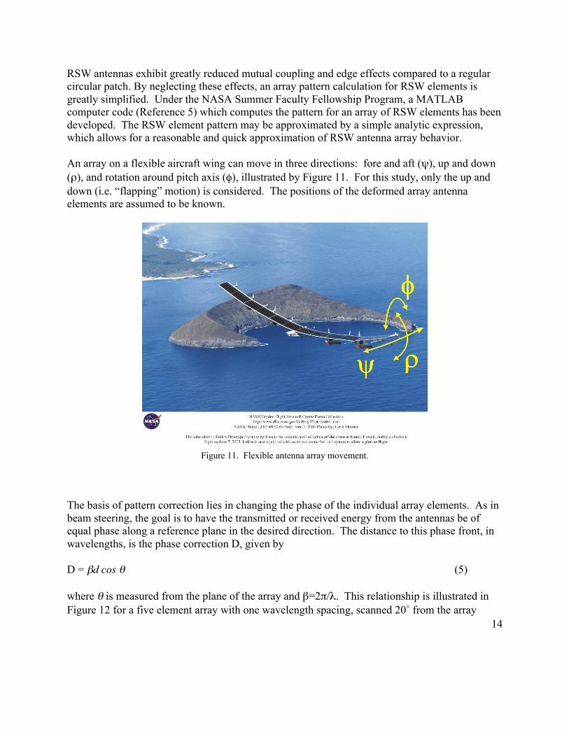
An array on a flexible aircraft wing can move in three directions: fore and aft (ψ), up and down(ρ), and rotation around pitch axis (φ), illustrated by Figure 11. For this study, only the up anddown (i.e. “flapping” motion) is considered. The positions of the deformed array antennaelements are assumed to be known.
Figure 11. Flexible antenna array movement.
The basis of pattern correction lies in changing the phase of the individual array elements. As inbeam steering, the goal is to have the transmitted or received energy from the antennas be ofequal phase along a reference plane in the desired direction. The distance to this phase front, inwavelengths, is the phase correction D, given by
D = βd cos θ (5)
where θ is measured from the plane of the array and β=2π/λ. This relationship is illustrated inFigure 12 for a five element array with one wavelength spacing, scanned 20˚ from the array

15
normal. It is observed that the main lobe of the pattern, the lobe of greatest gain, has expectedlyshifted by 20˚.
(a) Zenith looking array (b) Zenith radiation pattern
(c) Scanning array (d) Scanning radiation pattern
Figure 12. A planar antenna array with 20˚ scan angle from array normal.
As the array is flexed, the distance to the phase front changes and so the phase of each elementmust be adjusted such that
D = β(d1+d2) cos θ (6)

16
as shown by Figure 13.
Figure 13. Flexed antenna array.
The radiation pattern for a five element array, scanned 20˚, with parabolic deformation issimulated for 5.17 inch tip deflection, shown in Figure 14a. Phase correction is calculated foreach antenna in the array and the phase-adjusted array pattern is shown in Figure 14b.
(a) Flexed array radiation pattern (b) Flexed pattern with phase correction
Figure 14. Flexed array pattern with 5.17 inch tip displacement scanned 20˚ from array normal.
It is seen in the uncorrected pattern how array deformation has corrupted the planar pattern ofFigure 12d such that the direction of maximum gain has shifted and the scan direction of interesthas experienced gain loss. After correction, the main lobe is again observed at 20˚. The entirepattern is not recreated for every angle, but this is not necessary as we are only concerned withthe direction of interest. Note that although the main beam width is slightly decreased by using

17
this simple correction scheme, the amplitude at the beam maximum (in the direction of interest)is restored.
Calculating mutual coupling and antenna edge effects for a large antenna array is virtuallyimpossible. Neglecting these effects simplifies the simulation and, with approximation of theRSW radiation pattern and assuming each antenna’s position in space is known, results in areasonably valid correction scheme which should compare well with test measurements.
Summary and Conclusions
In support of the Multifunctional Structures and Materials Team, three antenna conceptscompatible with HALE UAVs have been developed. The antennas were designed to work at LBand / UHF frequencies since those frequencies are considered to present the biggest designchallenges for a lightweight, flexible structure such as a HALE UAV. Also, a phase correctiontechnique has been presented which allows for pattern correction for an array of RSW elements,by making the assumption that mutual coupling and edge effects are negligible for theseelements.

18
References
1. Stutzman, W. L., and Thiele, G. A.: Antenna Theory and Design, John Wiley & Sons, 1981.
2. Langley, J. D. S., Hall, P. S., and Newham, P.: Novel ultrawide-bandwidth Vivaldi antennawith low crosspolarisation. Electronics Letters, vol. 29, no. 23, pp. 2004-2005, Nov. 1993.
3. Lawrence, R. W., and Hilliard Larry: Mission Concept for the Remote Sensing of theCryosphere using Autonomous Aerial Observation Systems. Proceedings of SPIE vol. 5661Remote Sensing Applications of the Global Positioning Systems, Dec 2004
4. Khayat, M. A., Williams, J. T., Jackson, D. R., and Long, S. A.: Mutual Coupling BetweenReduced Surface-Wave Microstrip Antennas. IEEE Transactions on Antennas and Propagation,Vol. 48., No. 10, October 2000.
5. Baginsky, M. E.: “Patch2fast” code developed under the 2004 Summer Faculty FellowshipProgram with LaRC researcher Garnett Horner.

REPORT DOCUMENTATION PAGE Form ApprovedOMB No. 0704-0188
2. REPORT TYPE Technical Memorandum
4. TITLE AND SUBTITLE
Structurally Integrated Antenna Concepts for HALE UAVs5a. CONTRACT NUMBER
6. AUTHOR(S)
Cravey, Robin L.; Vedeler, Erik; Goins, Larry; Young, W. Robert; andLawrence, Roland W.
7. PERFORMING ORGANIZATION NAME(S) AND ADDRESS(ES)
NASA Langley Research CenterHampton, VA 23681-2199
9. SPONSORING/MONITORING AGENCY NAME(S) AND ADDRESS(ES)
National Aeronautics and Space AdministrationWashington, DC 20546-0001
8. PERFORMING ORGANIZATION REPORT NUMBER
L-19278
10. SPONSOR/MONITOR'S ACRONYM(S)
NASA
13. SUPPLEMENTARY NOTESAn electronic version can be found at http://ntrs.nasa.gov
12. DISTRIBUTION/AVAILABILITY STATEMENTUnclassified - UnlimitedSubject Category 32Availability: NASA CASI (301) 621-0390
19a. NAME OF RESPONSIBLE PERSON
STI Help Desk (email: [email protected])
14. ABSTRACT
This technical memorandum describes work done in support of the Multifunctional Structures and Materials Team under the VehicleSystems Program’s ITAS (Integrated Tailored Aero Structures) Project during FY 2005. The Electromagnetics and Sensors Branch (ESB)developed three ultra lightweight antenna concepts compatible with HALE UAVs (High Altitude Long Endurance Unmanned AerialVehicles). ESB also developed antenna elements that minimize the interaction between elements and the vehicle to minimize the impact ofwing flexure on the EM (electromagnetic) performance of the integrated array. In addition, computer models were developed to performphase correction for antenna arrays whose elements are moving relative to each other due to wing deformations expected in HALE vehicleconcepts. Development of lightweight, conformal or structurally integrated antenna elements and compensating for the impact of alightweight, flexible structure on a large antenna array are important steps in the realization of HALE UAVs for microwave applicationssuch as passive remote sensing and communications.15. SUBJECT TERMSAntenna design; Electromagnetic; HALE UAVs; Helios Prototype; Integrated Tailored Aero Structures; Remotely PilotedVehicles
18. NUMBER OF PAGES
2319b. TELEPHONE NUMBER (Include area code)
(301) 621-0390
a. REPORT
U
c. THIS PAGE
U
b. ABSTRACT
U
17. LIMITATION OF ABSTRACT
UU
Prescribed by ANSI Std. Z39.18Standard Form 298 (Rev. 8-98)
3. DATES COVERED (From - To)
5b. GRANT NUMBER
5c. PROGRAM ELEMENT NUMBER
5d. PROJECT NUMBER
5e. TASK NUMBER
5f. WORK UNIT NUMBER
732759.07
11. SPONSOR/MONITOR'S REPORT NUMBER(S)
NASA/TM-2006-214513
16. SECURITY CLASSIFICATION OF:
The public reporting burden for this collection of information is estimated to average 1 hour per response, including the time for reviewing instructions, searching existing data sources, gathering and maintaining the data needed, and completing and reviewing the collection of information. Send comments regarding this burden estimate or any other aspect of this collection of information, including suggestions for reducing this burden, to Department of Defense, Washington Headquarters Services, Directorate for Information Operations and Reports (0704-0188), 1215 Jefferson Davis Highway, Suite 1204, Arlington, VA 22202-4302. Respondents should be aware that notwithstanding any other provision of law, no person shall be subject to any penalty for failing to comply with a collection of information if it does not display a currently valid OMB control number.PLEASE DO NOT RETURN YOUR FORM TO THE ABOVE ADDRESS.
1. REPORT DATE (DD-MM-YYYY)
10 - 200601-