InTech-Planar Antenna Technology for Mm Wave Automotive Radar Sensing and Communications
FACULTY OF ENGINEERING AND SUSTAINABLE DEVELOPMENT...
NEW INTEGRATED SDARS ANTENNA ELEMENT
FOR AUTOMOTIVE APPLICATIONS
Muhammad Imtiaz
September 2011
Master’s Thesis in Electronics
Master’s Program in Electronics/Telecommunications
Examiner: Dr. José Chilo Supervisors: Dr. Jochen Christ
Dipl.-Ing. Mohammad Bashir


Dedicated To
My beloved parents & family who show me the right path to live successfully

Abstract
In the past few years the demand for light weight compact automotive antennas in the customers
desired mounting position has brought a challenge for the automotive antenna developers. Due to the
high demands for the accuracy and compactness it became very difficult to develop antenna elements
which fulfil all the strict requirements. Integrated SDARS (Satellite Digital Audio Radio Service)
antenna element is one of such tasks which require strong gain requirements at particular elevation
angles for the best reception of the satellite signals along with the car manufacturer’s desired mounting
positions.
To achieve the desired objectives for SDARS element, different antenna designs were proposed and
tested during the project work. Finally a newly developed two port cylindrical dielectric resonator
antenna (DRA) with a parasitic element is presented due to its high performance, simplicity and
compactness. The newly developed DRA antenna fulfils the strict SiriusXm gain requirements for the
challenging mounting position in the car. The SDARS antenna element is simulated using CST
Microwave Studio and verified by prototype measurements. The developed DRA antenna element has
a broad beam with a peak gain more than 6dBi at the null position. An axial ratio of less than 3dB is
achieved at the peak gain position. Real time 3D far field measurements are taken by using the MiDAS
4.1 system which verifies the simulated results of the developed integrated SDARS antenna. A good
agreement is achieved between the simulated and measured results.

Muhammad Imtiaz NEW INTEGRATED SDARS ANTENNA ELEMENT FOR AUTOMOTIVE APPLICATIONS
v
Acknowledgements
This thesis presents my research and development in Electronics engineering carried out at the antenna
development department of WISI Automotive, Germany, to fulfil the requirement for Master degree in
Electronics/Telecommunications at the University of Gävle, Sweden.
First of all I would like to thank Allah Almighty for His blessings and love. I would like to express my
sincere gratitude to my supervisors Dr. Jochen Christ and Dipl. –Ing. Mohammad Bashir for all their
support, encouragement, valuable guidance, technical training, and inspirations throughout my project
at the WISI Automotive. This work would not have been possible without their effort and support.
I would like to thank my academic advisor and examiner, Dr. José Chilo, for his kind guidance and
support.
I would like to express my gratitude to all staff members at WISI Automotive for providing me with
various supports, valuable talks and nice environments. I would like to express my appreciation to all
of my friends for their encouragement, support and prayers.
Last but not least, I would like to express my deepest gratitude to my parents and family for their
endless love, support, and encouragement throughout my life.

Muhammad Imtiaz NEW INTEGRATED SDARS ANTENNA ELEMENT FOR AUTOMOTIVE APPLICATIONS
vi
Table of contents
Abstract .................................................................................................................................................. iv
Acknowledgements ................................................................................................................................. v
Table of contents .................................................................................................................................... vi
List of Figures ...................................................................................................................................... viii
List of Abbreviations ............................................................................................................................... x
1 Introduction ..................................................................................................................................... 1
1.1 Background ............................................................................................................................. 1
1.2 Objective ................................................................................................................................. 2
1.3 Organization of the Report ...................................................................................................... 3
2 Theory ............................................................................................................................................. 4
2.1 Basic Antenna Theory ............................................................................................................. 4
2.2 Antenna Parameters ................................................................................................................. 4
2.2.1 Antenna Gain ................................................................................................................... 4
2.2.2 Scattering Parameters ...................................................................................................... 5
2.2.3 Polarization ...................................................................................................................... 5
2.2.4 Axial Ratio ...................................................................................................................... 6
2.2.5 Radiation Pattern ............................................................................................................. 7
2.2.6 Physical Size & Construction .......................................................................................... 7
2.3 Automotive Antennas .............................................................................................................. 7
2.4 Satellite Radio Services for Automotives................................................................................ 8
2.5 SDARS Antenna...................................................................................................................... 9
3 Design and Results ........................................................................................................................ 11
3.1 Numerical Simulations .......................................................................................................... 11
3.2 Measurement Setup ............................................................................................................... 11
3.3 Antenna Mounting Positions in Car ...................................................................................... 12
3.3.1 Top Roof Position ......................................................................................................... 13
3.3.2 Windscreen Position ...................................................................................................... 13

Muhammad Imtiaz NEW INTEGRATED SDARS ANTENNA ELEMENT FOR AUTOMOTIVE APPLICATIONS
vii
3.3.3 Spoiler Position ............................................................................................................. 14
3.4 Reference Antennas for the Measurements ........................................................................... 14
3.5 Proposed Antenna Elements .................................................................................................. 15
3.5.1 Ring Antenna Design .................................................................................................... 16
3.5.2 Circular Microstrip Patch Design .................................................................................. 16
3.5.3 Dielectric Resonator Antenna Design ........................................................................... 17
3.6 Comparison & Analysis of Proposed Designs ...................................................................... 18
3.7 Results of Dielectric Resonator Antenna .............................................................................. 19
3.7.1 Return Loss of DRA ...................................................................................................... 19
3.7.2 Axial Ratio of DRA ....................................................................................................... 20
3.7.3 Effect of Parasitic Element ............................................................................................ 21
3.7.4 Optimization of the DRA .............................................................................................. 22
3.8 DRA Simulation Results ....................................................................................................... 23
3.8.1 Roof Top Position ......................................................................................................... 23
3.8.2 Windscreen Position ...................................................................................................... 24
3.8.3 Spoiler Position ............................................................................................................. 25
3.9 DRA Measurement Results ................................................................................................... 26
3.9.1 Roof Top Position ......................................................................................................... 26
3.9.2 Windscreen Position ...................................................................................................... 27
3.9.3 Spoiler Position ............................................................................................................. 28
3.10 Discussion ............................................................................................................................. 29
4 Conclusions and Future Work ....................................................................................................... 31
References ............................................................................................................................................. 32
Appendix A: Measured reference antennas .......................................................................................... A1
Appendix B: Measured proposed antennas ........................................................................................... B1
Appendix C: Measure DRA in comparison to reference antenna ......................................................... C1

Muhammad Imtiaz NEW INTEGRATED SDARS ANTENNA ELEMENT FOR AUTOMOTIVE APPLICATIONS
viii
List of Figures
Fig. 1.1: SiriusXM gain requirements for SDARS antenna
Fig.1.2: MiDAS 3D far field Test Setup
Fig.1.3: Antenna mounting position (a) in car (b) Top roof position
Fig.1.4: windscreen position
Fig.1.5: Spoiler position.
Fig.1.6: Linearly polarized reference antenna
Fig.1.7: Circularly polarized reference antenna
Fig.1.8: Proposed designs (a) L-shaped patch antenna (b) Z-element (c) Single T-slot
Fig.1.9: Ring antenna (a) simulated design in cavity (b) ring element in space
Fig.1.10: Circular patch antenna (a) design in space (b) simulated design in cavity (c) feed network
Fig.1.11: Dielectric resonator antenna (DRA)
Fig.1.12: Simulated return loss of DRA
Fig.1.13: Measured return loss of DRA
Fig.1.14: Axial ratio of the simulated DRA
Fig.1.15: Axial ratio of the measured DRA
Fig.1.16: Measured effects of p-element on the DRA
Fig.1.17: Simulated design of the DRA in the top roof position
Fig.1.18: Simulated co-polarization of the DRA in the top roof position
Fig.1.19: Simulated design of the DRA in the windscreen position
Fig.1.20: Simulated co-polarization of the DRA in the windscreen position
Fig.1.21: Simulated design of the DRA in the spoiler position
Fig.1.22: Simulated co-polarization of the DRA in the spoiler position
Fig.1.23: Measured design of the DRA in the top roof position
Fig.1.24: Measured co-polarization of the DRA in the top roof position
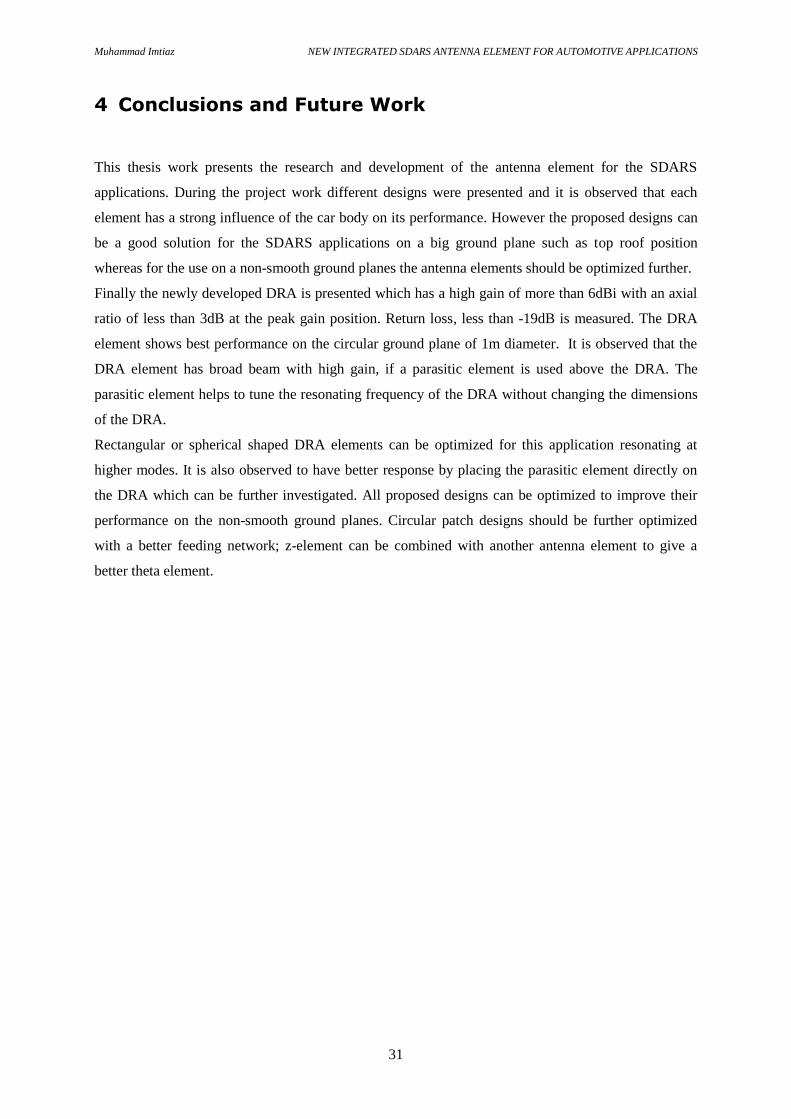
Fig.1.25: Measured design of the DRA in the windscreen position
Fig.1.26: Measured co-polarization of the DRA in the windscreen position
Fig.1.27: Measured design of the DRA in the spoiler position
Fig.1.28: Measured co-polarization of the DRA in the spoiler position
Fig.1.29: Comparison of the measured co-polarizations of the DRA
Figures from Appendix A: Measured reference antennas
Fig.A.1: Measured LHCP for cross dipole at 2320 MHz
Fig.A.2: Measured vertical component of quarter wave monopole at 2320 MHz
Muhammad Imtiaz NEW INTEGRATED SDARS ANTENNA ELEMENT FOR AUTOMOTIVE APPLICATIONS
ix
Figures from Appendix B: Measured proposed antennas
Fig.B.1: L-shaped patch measured design in windscreen car cavity
Fig.B.2: Measured Z-element design
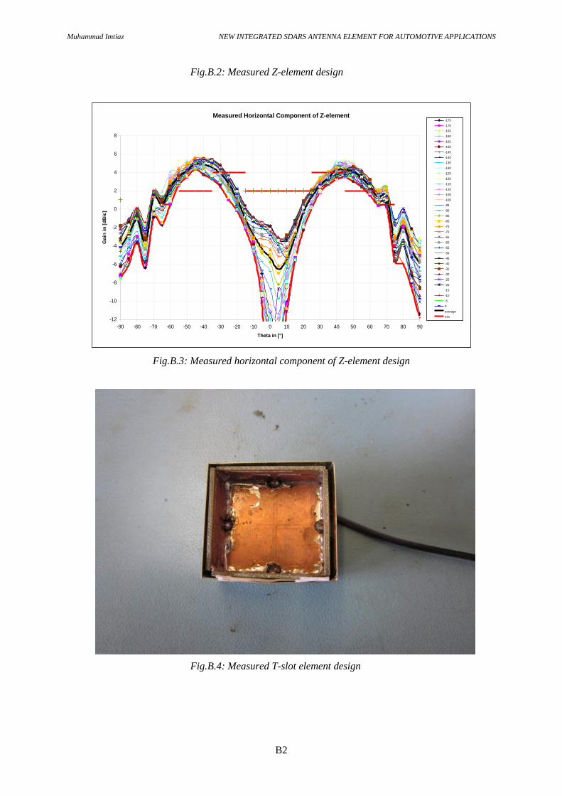
Fig.B.3: Measured horizontal component of Z-element design
Fig.B.4: Measured T-slot element design
Fig.B.5: Measured vertical component of T-slot element design
Fig.B.6: Measured ring antenna design
Fig.B.7: Measured co-polarization of the ring antenna at 2320MHz
Fig.B.8: Measured circular patch antenna design
Fig.B.9: Measured co-polarization of the circular patch antenna
Figures from Appendix C: Measured DRA in comparison to reference antenna
Fig.C.1Comparison of the measured reference antenna and DRA at Top roof position
Fig.C.2: Comparison of the measured reference antenna and DRA at windscreen position
Fig.C.3: Comparison of the measured reference antenna and DRA at spoiler position
Muhammad Imtiaz NEW INTEGRATED SDARS ANTENNA ELEMENT FOR AUTOMOTIVE APPLICATIONS
x
List of Abbreviations
SDARS Satellite Digital Audio Radio Service
DRA Dielectric Resonator Antenna
LHCP Left Hand Circular Polarized
RHCP Right Hand Circular Polarized
LP Linearly Polarized
GEO Geosynchronous Earth Orbit
LEO Low Earth Orbit
MEO Medium Earth Orbit
LTE Long Term Evolution
UMTS Universal Mobile Telecommunication System
GSM Global System of Mobiles
DAB Digital Audio Broadcast
DVB Digital Video Broadcast
WLAN Wireless Local Area Network
GPS Global Positioning System
FM Frequency Modulated
AM Amplitude Modulated
C2C Car to Car Communication
VICS Vehicle Information and Communication System

Muhammad Imtiaz NEW INTEGRATED SDARS ANTENNA ELEMENT FOR AUTOMOTIVE APPLICATIONS
xi

Muhammad Imtiaz NEW INTEGRATED SDARS ANTENNA ELEMENT FOR AUTOMOTIVE APPLICATIONS
1
1 Introduction
Due to the increasing demand of infotainment and multimedia services with high performance in the
daily life it also became field of interest for the automotive industry to bring the same services
available for the car customers while driving on the road. To provide various high performance
multimedia and infotainment services such as HD Audio/Video services, GPS, Cellular, SDARS,
WLAN and Bluetooth within the car with least effects on the performance, weight, excellence and
design of the car it became more challenging and important for the car manufacturers to design such
innovative technologies.
Satellite Digital Audio Radio Service (SDARS) is a digital satellite radio service available in the
content of USA and Canada provided by the SiriusXm. SDARS uses two GEO and three LEO
satellites to provide its digital radio services with both high quality and large quantity. SDARS also
provides some video channels along with large choice of audio radio channels. One of the potential
customers for the SDARS is the automotive industry as the car customers desire to have high
performance infotainment services available in the car.
To provide the satellite radio with in the cars is a big challenge due to the strict conditions for satellite
signal availability, car performance issues and car body effects. Considering all these effects the car
manufacturer demands for compact, lightweight and high gain SDARS antenna element.
1.1 Background
Automotive vehicles are increasingly being equipped with special electronic modules such as global
positioning system, telematics and infotainments devices that require wireless data communications.
One such system is SDARS which employs the wireless technology to provide satellite digital audio
radio service. Antennas for SDARS should be able to receive an optimal satellite signal at particular
elevation angles.
A lot of work is done to improve the performance and compactness of the SDARS antenna elements in
past few years. Reference [1] describes an overview of SDARS automotive antennas available in the
market. Different types of antenna elements such as microstrip patch, probe feed patch and ceramic
patch antennas are in the market for SDARS applications. The different solutions available in
literature are the quadrifilar antenna, as in [2], the standard dual polarized antennas, as in [3-7], or the
low profile antenna, as in [8]).
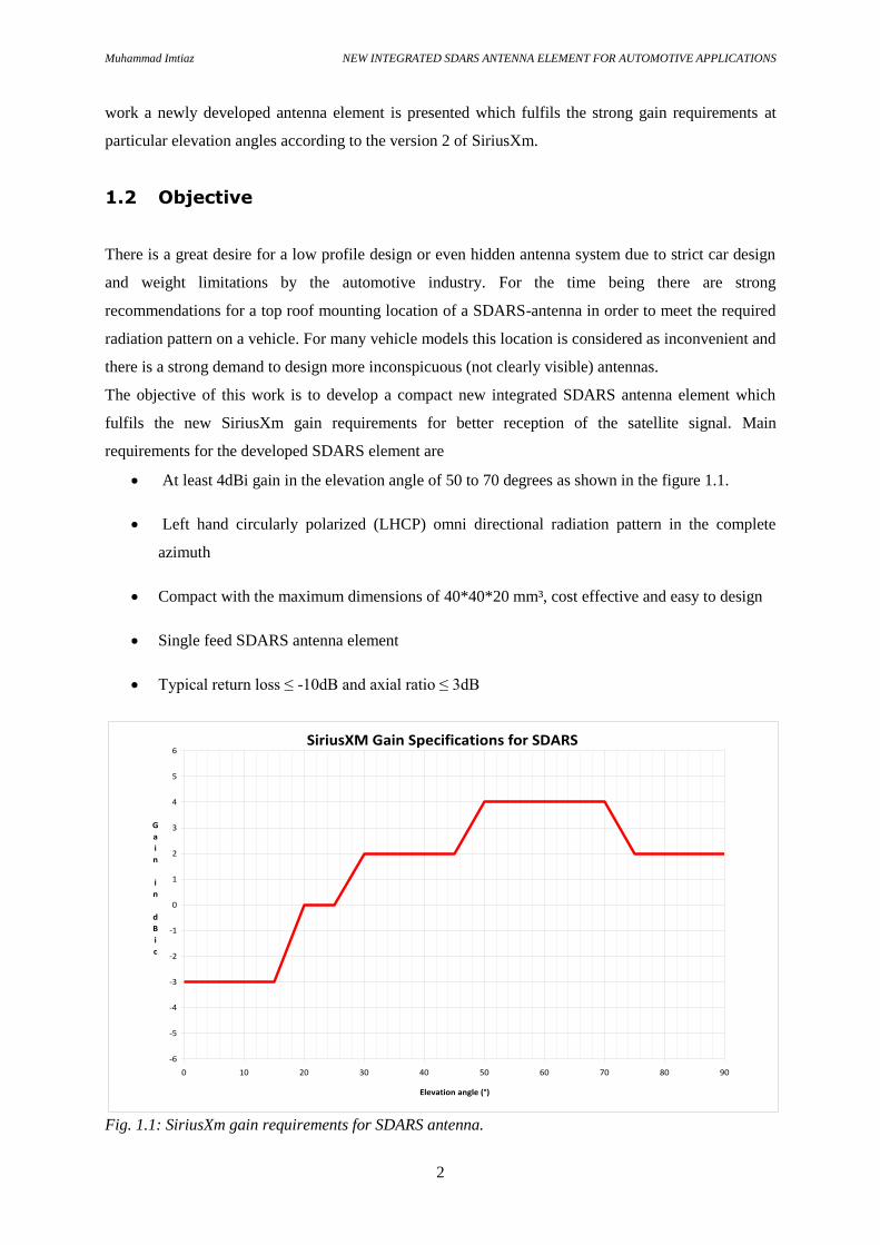
Most of the antennas available in the field are complex and expensive which fulfils the version 1 of the
SiriusXm gain requirements. However gain requirements are revised by the SiriusXm in version 2
with more strong gain requirements. In version 1 a maximum gain of 3dBi is acceptable but in version
2 it is required to have at least 4dBi gain at the particular elevation angles as shown in fig. 1.1. In this
Muhammad Imtiaz NEW INTEGRATED SDARS ANTENNA ELEMENT FOR AUTOMOTIVE APPLICATIONS
2
work a newly developed antenna element is presented which fulfils the strong gain requirements at
particular elevation angles according to the version 2 of SiriusXm.
1.2 Objective
There is a great desire for a low profile design or even hidden antenna system due to strict car design
and weight limitations by the automotive industry. For the time being there are strong
recommendations for a top roof mounting location of a SDARS-antenna in order to meet the required
radiation pattern on a vehicle. For many vehicle models this location is considered as inconvenient and
there is a strong demand to design more inconspicuous (not clearly visible) antennas.
The objective of this work is to develop a compact new integrated SDARS antenna element which
fulfils the new SiriusXm gain requirements for better reception of the satellite signal. Main
requirements for the developed SDARS element are
At least 4dBi gain in the elevation angle of 50 to 70 degrees as shown in the figure 1.1.
Left hand circularly polarized (LHCP) omni directional radiation pattern in the complete
azimuth
Compact with the maximum dimensions of 40*40*20 mm³, cost effective and easy to design
Single feed SDARS antenna element
Typical return loss ≤ -10dB and axial ratio ≤ 3dB
Fig. 1.1: SiriusXm gain requirements for SDARS antenna.
SiriusXM Gain Specifications for SDARS
-6
-5
-4
-3
-2
-1
0
1
2
3
4
5
6
0 10 20 30 40 50 60 70 80 90
Elevation angle (°)
G
a
i
n
i
n
d
B
i
c

Muhammad Imtiaz NEW INTEGRATED SDARS ANTENNA ELEMENT FOR AUTOMOTIVE APPLICATIONS
3
1.3 Organization of the Report
The project report is organized as follows:
Chapter 2: Theory An introduction to the basic antenna theory related to the project work is given in
this chapter. A brief description of the automotive and SDARS antenna element and its important
requirements mandatory for its application in the automotive industry is given in the chapter.
Chapter 3: Design and Results a detailed description of the different proposed antenna designs is
given here including their simulation and measurement results. A comparison with the finally selected
SDARS antenna element with a detailed presentation and analysis of the finally developed SDARS
antenna element. Finally a brief discussion summarizes the results obtained during the project work
for DRA.
Chapter 4: Conclusions and Future Work to summarize the work carried out in this report a
conclusion is given here along with some possible future work related to the project.
Muhammad Imtiaz NEW INTEGRATED SDARS ANTENNA ELEMENT FOR AUTOMOTIVE APPLICATIONS
4
2 Theory
Selection of a suitable antenna element is the first and most important task for the development of an
antenna design. In this chapter the theoretical part of the project is presented in detail which is latter
implemented to complete the project.
2.1 Basic Antenna Theory
A device which can transmit and receive electromagnetic waves can be defined as an antenna. In an
antenna, the direction of radiated power focuses on itself structure or shape. Like a dipole antenna has
the properties of omni directional antenna in the azimuth. However, a horn antenna only has a
dominated directional radiated power when it is working [9].
Antennas are widely used in radio frequency range as a key component of radio communication
system. There many different types of antennas depending on their electrical characteristics, shape,
size such as monopole, dipole, parabolic, micro strip , dielectric resonators, PIFA, yagi etc.
2.2 Antenna Parameters
Antenna performance varies depending on the geometry, physical size, environment and electrical
characteristics of the antenna. Some important antenna parameters, which define the electrical
characteristics of the antenna, such as antenna gain, s-parameters, polarization and radiation pattern
are discussed below.
2.2.1 Antenna Gain
The gain of the antenna can be defined as “the ratio of the radiation intensity in a given direction to the
accepted radiation intensity being radiated from the source in homogenously in all directions”. Gain
can be calculated by the following equation
G (θ, Φ) = 4
(dimensionless) (1)
Here G (θ, Φ) = Gain in θ and Φ directions
U (θ, Φ) = Radiation intensity in θ and Φ directions
Pin = Total input (accepted) power

Muhammad Imtiaz NEW INTEGRATED SDARS ANTENNA ELEMENT FOR AUTOMOTIVE APPLICATIONS
5
Antenna gain can also be defined in terms of directivity and the antenna efficiency.
G (θ, Φ) = k ∙ D (θ, Φ) (dimensionless) (2)
Here D (θ, Φ) is the directivity, a measure of radiation intensity in a particular direction, and k (0 ≤ k ≤
1) is the efficiency factor of the antenna. If the antenna efficiency is less than 100 percent, the gain is
less than the directivity. The antenna efficiency depends on the ohmic losses of the antenna, which are
due to the non-radiated power of the antenna causing increase in temperature of the antenna structure
[10].
2.2.2 Scattering Parameters
For every antenna design scattering parameter is the most important parameter to analyse and compare
the performance of the designed antenna. Scattering parameters provides the information for the
resonating frequency, bandwidth, impedance match, power transmitted & reflected and coupling
effects between the ports. In the thesis work most important S-parameter is S11 also called return loss.
The return loss of antenna gives the information that how much of the incident power is reflected
instead of being transmitted [11]. In the presented work S11 is measured in dB. A lower value of S11
means most of the input power is transmitted through the network that is antenna and the feed network
is well matched. For example if S11 = −10dB, it means that 90 parent of the incident power will be
transmitted through the network. It is defined as
|S11|dB = 20log|Γ| (3)
Where |Γ| = SWR − 1 (4)
SWR + 1
Here Γ = reflection coefficient
S11 = return loss
SWR = standing wave ratio
In this project a typical value of the return loss (S11) of -10dB needs to be maintained for the whole
operating frequency band of 25MHz.
2.2.3 Polarization
Polarization of the plane wave refers to the orientation of the electric field vector, which may be in a
fixed direction or may change with time [12]. The polarization of an antenna is defined as the
polarization of the wave radiated when the antenna is excited, or the polarization of an incident wave
Muhammad Imtiaz NEW INTEGRATED SDARS ANTENNA ELEMENT FOR AUTOMOTIVE APPLICATIONS
6
which results in maximum available power at the antenna. Polarization of a wave can be classified into
linear, circular and elliptically polarized waves.
Linear polarization is obtained if the field vector (electric or magnetic) possesses only one component
or two orthogonal linear components that are out of phase by 180˚. Linearly polarized wave has either
vertical (Eθ) or horizontal (EΦ) component of the filed vector [12].
Circular polarization occurs when the two linear orthogonal components have equal magnitude and
the time-phase difference between them is odd multiples of π/2. If the magnitudes are different,
elliptical polarization is obtained. Clock wise rotation of the field vector is designated as the right hand
circularly polarized (RHCP) wave and counter clock wise rotation of the field vector as left hand
circularly polarized wave (LHCP). Left and right hand field components can be calculated from the
tangential components as follows [13]
Eleft
(Eθ – i EΦ) (5)
Eright
(Eθ + i EΦ) (6)
Here
Eleft = Left hand circularly polarized field component
Eright = Right hand circularly polarized field component
Eθ = Vertical field component
EΦ = Horizontal field component
2.2.4 Axial Ratio
The axial ratio is the ratio of orthogonal components (horizontal and vertical) of an E-field. The axial
ratio for an ellipse is larger than 1 (>0 dB). The axial ratio for pure linear polarization is infinite,
because the orthogonal components of the field are zero.
An ideal circularly polarized antenna means equal magnitude of the orthogonal horizontal and vertical
components and so the axial ratio is 1 (or 0 dB). In addition, the axial ratio tends to degrade away from
the main beam of an antenna. As the designed antenna is circularly polarized so axial ratio is an
important parameter to measure the circularity of the antenna. An axial ratio of at least 3dB is desired
in the main beam direction of the designed SDARS antenna. Axial ratio can be calculated by the
following formula
XPD = 20 log ((A.R+1)/(A.R-1)) dB (7)
Where
A.R= axial ratio (linear)
XPD= cross polarization discrimination

Muhammad Imtiaz NEW INTEGRATED SDARS ANTENNA ELEMENT FOR AUTOMOTIVE APPLICATIONS
7
2.2.5 Radiation Pattern
The radiation pattern of an antenna is a plot of the magnitude of the far-zone field strength versus
position around the antenna, at a fixed distance from the antenna [14].
The antenna radiation patterns can be either plotted for the elevation plane ´θ´ or for the azimuth plane
´Φ´. Typically radiation patterns are measured in two dimensional and three dimensional graphs which
show the generated field strengths away from antenna at a certain distance. Spherical (r, θ, Φ), polar (r,
Φ) or (r, θ) and rectilinear (x, y) coordinate system are used to represent radiation pattern of the
antennas. Radiation patterns generated by the antenna mainly depends on the geometry, material,
physical size and its electrical characteristics. Antennas have isotropic, directional, omnidirectional
radiation patterns.
2.2.6 Physical Size & Construction
Physical size and the construction of the antenna is one of the important parameters which effects the
electrical characteristics and performance of the antenna. Size of the antenna mainly depends on the
operating frequency. Normally at higher frequencies due to small wavelength size of the antenna
decreases and vice versa. Antennas can be constructed in many different ways e.g. simple wire
antennas, patch antennas, micro strip antennas, reflector antennas, aperture antennas, horn antennas
etc. When considering antennas suitable at 2.320 GHz (λ ≈ 129mm) frequency for the SDARS
application a compact and light weight antenna is desired with high gain.
2.3 Automotive Antennas
The mobility by vehicles is indispensable for our personal lives as well as business activities. There
have been strong requirements of safety, comfortable time & space, and convenience for the mobility
by vehicles.
Initially AM radio reception was only available in vehicles. Several systems for these requirements
have been gradually installed into vehicles with the growth of wireless technologies [15], [16]. FM
radio and television (TV) programs can be currently received in vehicles by FM/AM, SDARS, DAB,
DVB etc. Drivers can achieve information of own positions by Global Positioning Systems (GPS) and
congestion information by Vehicle Information and Communication systems (VICS). Telephone can
be used in vehicle and Bluetooth helps links between mobile terminals of driver and vehicle terminals.
Laser radars and millimeter-wave radars have been installed as forward looking sensors [17].
Automotive antenna design technique is one of the key techniques to contribute the system realization
very much. Automotive antennas generally need simple architectures and low cost due to consumer
products, and compactness or low profile due to limited installation spaces of vehicle. Also, inclusion

Muhammad Imtiaz NEW INTEGRATED SDARS ANTENNA ELEMENT FOR AUTOMOTIVE APPLICATIONS
8
of the vehicle body into the antenna design is needed, when antenna performance is strongly affected
by the vehicle body.
The frequency bands used in automotive wireless systems range widely from AM band to the
millimetre-wave band. The different frequency bands result in the different problems and difficulties
of the development of antennas. The establishment of automotive antenna design techniques is needed
in wide frequency range.
2.4 Satellite Radio Services for Automotives
With the increasing demand for connectivity anywhere and anytime, the satellite services market is
contributing to improve the available services to the automotive market. The main automotive and
mobile technologies today available, or under development, through the satellite providers are using L
and S band, and are able to provide satellite internet access, satellite phone, satellite radio, satellite
television and satellite navigation.
While different satellite services are used to deliver the mentioned technologies to end users, the
following table 1 depicts some of the main services used for automotive, nautical or air markets in L/S
band [18].
Table 1: satellite technologies used in the automotive market [18]
Service Operating frequency Polarization Orbit
Thuraya or
Inmarsat BGAN
Downlink: 1525 to 1560
MHz;
Uplink: 1625 to 1660
MHz
Dual switchable SAT
(LHCP or RHCP)
GEO
(Geosynchrornous
orbit)
Global
Navigation
Satellite Systems
(i.e. GPS and
Galileo)
Downlink: 1575 MHz RHCP MEO (Medium earth
orbit)
Iridium Uplink /Downlink: 1610 to
1626
MHz
RHCP LEO (Low earth orbit)
Globalstar Downlink: 1610 to 1626
MHz.
Downlink: 2484 to 2499
MHz
LHCP LEO
DVB-SH Downlink: 2170 to 2200 Dual switchable SAT GEO

Muhammad Imtiaz NEW INTEGRATED SDARS ANTENNA ELEMENT FOR AUTOMOTIVE APPLICATIONS
9
MHz;
Uplink: 1980 to 2010
MHz
(LHCP or RHCP) and
TER (LP)
SDARS Downlink:2320 to 2345
MHz
Dual SAT (LHCP)
and
TER (LP)
GEO, LEO
The data in the table show the frequencies used for each service, specifying the transmission from
earth to satellite (uplink) and the transmission from satellite to earth (downlink) bands. For each
service the polarizations required by the antenna specifications is specified, discriminating between
the LHCP (Left Hand Circular Polarization), the RHCP (Right Hand Circular Polarization) and the LP
(Linear Polarization).
2.5 SDARS Antenna
SDARS (satellite digital audio radio service) is a satellite service used to provide digital radio to end
users. Starting from its first requirements release ([19] [20]), it was underlined that the circularly
polarized satellite signal should reach the users in the open areas, being further supported by terrestrial
transmitters providing the necessary coverage especially in the urban environment, where the satellite
signal could be obstructed by buildings or other constructions.
Since several years, SDARS is available in USA and Canada [21], and the service is in operation in
the S-band (from 2320 to 2345 MHz), employing dual transmission broadcast format: LHCP signals
provided by satellites and LP signals radiated by terrestrial stations. Currently SiriusXm is using a
network of five satellites including two GEO and three LEO satellites. GEO is a very common
Geosynchronous orbit at the altitude of 35,786km from the Earth whereas LEO is a small low earth
orbit with an altitude less than 2000km above the Earth [14]. The network of the satellites operates in
such a way that for complete 24 hours of the day, at least one satellite is visible to the SDARS receiver
antennas. Unlike global positioning system (GPS) which has a large network of satellites with at least
satellite availability of 5 to 6 at a time for its customers. SDARS network of satellite can provide about
2 to 3 satellites in most of the time in a day except a small interval of time when only one satellite is
visible to the SDARS receivers. This is why SDARS antenna needs strict gain requirements for high
performance and to provide the satellite digital radio service available every time for the users.
Operating satellite system by SiriusXm, for SDARS, uses right hand circularly polarized (RHCP)
antenna for the uplink communications whereas for the downlink communications SDARS antenna
element uses left hand circularly polarized (LHCP) radiation pattern. To enhance the reliability,
overall throughput of the system and performance circularly polarized antennas are required.

Muhammad Imtiaz NEW INTEGRATED SDARS ANTENNA ELEMENT FOR AUTOMOTIVE APPLICATIONS
10
The automotive SDARS antennas implement such as dual polarized system either with two separate
antennas (dual–arm solution), one optimized for the LP terrestrial reception and the other for the
LHCP satellite one; or with a single antenna (single-arm solution) receiving both signals. However
now a days antenna element for satellite communication is main topic of interest in SDARS
application due to its high performance, quality and complexity instead of terrestrial antenna.

Muhammad Imtiaz NEW INTEGRATED SDARS ANTENNA ELEMENT FOR AUTOMOTIVE APPLICATIONS
11
3 Design and Results
An overview of the measurement and simulation tools is given in the beginning in the chapter. Some
important proposed antenna elements and their performance issues are discussed in detail here. A
comparison of the proposed designs is given and finally the simulation and measurement results for
the best selected design are analysed and discussed in detail.
3.1 Numerical Simulations
Computer simulation technology (CST) provides the 3D electromagnetic field simulation tool CST
Microwave Studio (MWS). A full-wave electromagnetic field simulator such as CST models and
computes the interaction of electromagnetic fields with the physical object and environment. The
software efficiently uses Maxwell's equations to calculate antenna performance, electromagnetic
compatibility, radar cross section and electromagnetic wave propagation, etc. [13]. It offers the
different solvers such as Time and Frequency domain solvers.
In the presented work CST MWS is used for the numerical simulations of the designed antenna
elements. Broadband calculations for operating frequency, S-parameters and the radiation patterns
were analysed and optimized by CST MWS. CST MWS gives the possibility to optimize the design
for the defined goals or optimize and analyse the individual design parameter by setting parameter
sweep. Both tools parameter sweep and optimization tool, in CST MWS, are efficiently used thought
out the project work for the in depth analysis of the designed antenna models. All simulated results
were well verified by the real time measurements of the prototypes.
3.2 Measurement Setup
MiDAS 4.1 system by Orbit/FR is used for the real time 3D far field radiation pattern
measurements of the designed antennas. MiDAS system has the capability to measure real time 3D,
2D and 1D far field radiation patterns for the antenna elements. It has the capability to measure
vertical, horizontal and circularly polarized (LHCP, RHCP) antenna elements. By control module of
the MiDAS system the test antenna can be rotated in the six different axes. In the measurement
scenario test antenna is placed about 20m away and 7m high from the transmit antenna as shown in
fig. 1.2. Transmit antenna has the capability to transmit circular (LHCP, RHCP) and linearly
(Horizontal, Vertical) polarized waves within a frequency range of 1 to 18 GHz [17]. Transmit
antenna throughout the measurements, remain fixed at the lower end directed towards the receiver.
Before the measurement starts transmit and receive antennas are aligned in their LOS and then control

Muhammad Imtiaz NEW INTEGRATED SDARS ANTENNA ELEMENT FOR AUTOMOTIVE APPLICATIONS
12
module automatically adjusts the position of the test antenna to -90 degrees. It is possible to control
the rotation and movement of the axes either manually or automatically.
Fig.1.2: MiDAS 3D far field test setup
MiDAS system calculates the receive power (dBm) by rotating the test antenna from -90 degrees to
+90 degrees with the step of 5 degrees on axis 3 (elevation plane). On each 5 degree step the test
antenna is rotated about its axis 4 (phi-plane) by 360 degrees. To measure more accurate and detailed
radiation patterns, the step on the elevation plane can be reduced to 1 degree. In these measurements
hemispherical 3D radiation pattern is obtained for the test antenna which gives the information for the
received signal power at the test antenna.
3.3 Antenna Mounting Positions in Car
Most challenging task of this project is to make a compact SDARS antenna element which fits well
into the small space of the car mounting position. There are many different antenna mounting
positions in the car for different antenna services as shown in fig. 1.3(a). However for the SDARS
element the desired mounting positions are 7, 4 and 3 as shown in fig. 1.3(a).
Test antenna
-plane
-plane
Transmit antenna

Muhammad Imtiaz NEW INTEGRATED SDARS ANTENNA ELEMENT FOR AUTOMOTIVE APPLICATIONS
13
(a)
(b)
Fig.1.3: Antenna mounting position (a) in car (b) Top roof position.
3.3.1 Top Roof Position
Third possible position for mounting the SDARS antenna element in the car is at top roof as shown in
figure 1.3(b). This position is the most suitable place for mounting the antenna element on the car to
get best possible quality of receive signal. It is because at the top roof, antenna element has no cavity
and no edges near to it also a big ground plane is available around the antenna by the metal roof of the
car. In this position the available cavity dimension is 50*50*20 mm3.
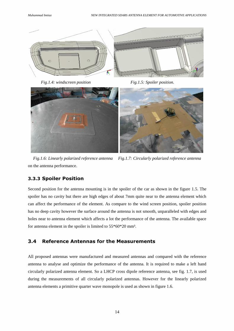
3.3.2 Windscreen Position
The most desired mounting position was just below the wind screen, inside the car. At this position
maximum possible space for the complete SDARS antenna element is 41*42*20 mm³ with a tilt of 10
degree towards the driving direction. In this position distance between the wind screen glass and the
antenna mounting position is only 5.6mm. To avoid wind screen glass of the car and its effects on the
antenna performance, at maximum the antenna element is allowed to have only 2.5mm space out of
the cavity. The car cavity for this position is shown in figure 1.4. In this project work windscreen
position is considered initially for the antenna measurements due to its strong requirement and effects
Muhammad Imtiaz NEW INTEGRATED SDARS ANTENNA ELEMENT FOR AUTOMOTIVE APPLICATIONS
14
Fig.1.4: windscreen position Fig.1.5: Spoiler position.
Fig.1.6: Linearly polarized reference antenna Fig.1.7: Circularly polarized reference antenna
on the antenna performance.
3.3.3 Spoiler Position
Second position for the antenna mounting is in the spoiler of the car as shown in the figure 1.5. The
spoiler has no cavity but there are high edges of about 7mm quite near to the antenna element which
can affect the performance of the element. As compare to the wind screen position, spoiler position
has no deep cavity however the surface around the antenna is not smooth, unparalleled with edges and
holes near to antenna element which affects a lot the performance of the antenna. The available space
for antenna element in the spoiler is limited to 55*60*20 mm³.
3.4 Reference Antennas for the Measurements
All proposed antennas were manufactured and measured antennas and compared with the reference
antenna to analyse and optimize the performance of the antenna. It is required to make a left hand
circularly polarized antenna element. So a LHCP cross dipole reference antenna, see fig. 1.7, is used
during the measurements of all circularly polarized antennas. However for the linearly polarized
antenna elements a primitive quarter wave monopole is used as shown in figure 1.6.

Muhammad Imtiaz NEW INTEGRATED SDARS ANTENNA ELEMENT FOR AUTOMOTIVE APPLICATIONS
15
During all measurements the reference antenna is placed on a 1m circular ground plane without car
cavity. However the test antennas are measured in the three different car positions. As all
measurements during this project were done in an open air environment so for each test antenna
measurement, reference antenna is measured in the same weather environment to make exact
comparison. At 2320MHz 3D far field radiation patterns for the reference antennas were measured,
see Appendix A.
3.5 Proposed Antenna Elements
During the project work different antenna elements such as cross dipole, PIFA, patch antennas, ring
antenna, dielectric resonator antennas etc. were designed for the required objectives. Few important
designs are discussed in this report. Following designs were simulated and measured with the
prototype design. Finally by comparison the best suitable design was selected. Mainly radiation
pattern, circularity and gain of the proposed designs were focused for the initial results which are
presented here. Manufactured prototypes of the proposed designs and their measured results with
SDARS gain specifications are shown in Appendix B.
Fig.1.8: Proposed designs (a) L-shaped patch antenna (b) Z-element (c) single T-slot
Initially L-shaped patch design shown in fig. 1.8 (a) is tested and verified by the MiDAS system.
However the simulated and measured results for L-shape patch design has shown that the design does
not fulfil the SiriusXm gain requirements.
Another design with a Z-element surrounded by four T-slots is simulated and tested. The simulation
results fulfils the requirement however the measured design for the T-slot has less as compare to the
simulated result. Also the complete design is complex to manufacture with five ports which also
makes this design expensive.
(a)
(b)
(c)
Muhammad Imtiaz NEW INTEGRATED SDARS ANTENNA ELEMENT FOR AUTOMOTIVE APPLICATIONS
16
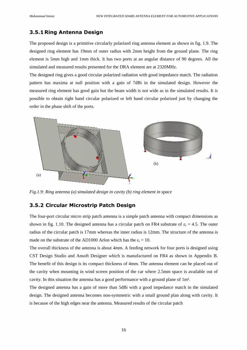
3.5.1 Ring Antenna Design
The proposed design is a primitive circularly polarized ring antenna element as shown in fig. 1.9. The
designed ring element has 19mm of outer radius with 2mm height from the ground plane. The ring
element is 5mm high and 1mm thick. It has two ports at an angular distance of 90 degrees. All the
simulated and measured results presented for the DRA element are at 2320MHz.
The designed ring gives a good circular polarized radiation with good impedance match. The radiation
pattern has maxima at null position with a gain of 7dBi in the simulated design. However the
measured ring element has good gain but the beam width is not wide as in the simulated results. It is
possible to obtain right hand circular polarized or left hand circular polarized just by changing the
order in the phase shift of the ports.
Fig.1.9: Ring antenna (a) simulated design in cavity (b) ring element in space
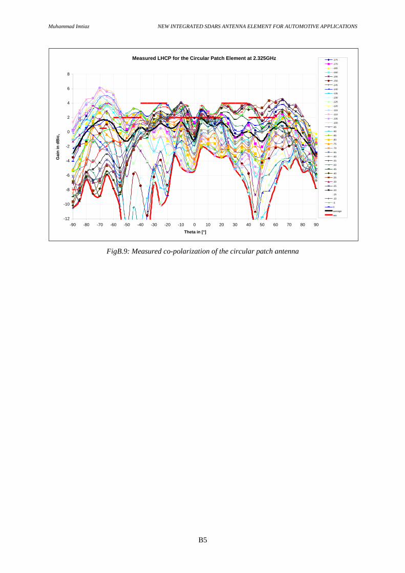
3.5.2 Circular Microstrip Patch Design
The four-port circular micro strip patch antenna is a simple patch antenna with compact dimensions as
shown in fig. 1.10. The designed antenna has a circular patch on FR4 substrate of εr = 4.5. The outer
radius of the circular patch is 17mm whereas the inner radius is 12mm. The structure of the antenna is
made on the substrate of the AD1000 Arlon which has the εr = 10.
The overall thickness of the antenna is about 4mm. A feeding network for four ports is designed using
CST Design Studio and Ansoft Designer which is manufactured on FR4 as shown in Appendix B.
The benefit of this design is its compact thickness of 4mm. The antenna element can be placed out of
the cavity when mounting in wind screen position of the car where 2.5mm space is available out of
cavity. In this situation the antenna has a good performance with a ground plane of 1m².
The designed antenna has a gain of more than 5dBi with a good impedance match in the simulated
design. The designed antenna becomes non-symmetric with a small ground plan along with cavity. It
is because of the high edges near the antenna. Measured results of the circular patch
(b)
(a)

Muhammad Imtiaz NEW INTEGRATED SDARS ANTENNA ELEMENT FOR AUTOMOTIVE APPLICATIONS
17
Fig.1.10: Circular patch antenna (a) design in space (b) simulated design in cavity (c) feed network
element are not good. It has low gain with high axial ratio. However the antenna element can be
improved by the further optimization of the antenna parameters and the feeding network.
3.5.3 Dielectric Resonator Antenna Design
Dielectric resonator antenna (DRA) is a two port cylindrical element with a radius of 13mm and height
of 10mm. Two metal strips are used with the width of 1mm and height of 9mm spaced with 90 degree
angular distance around the DRA as shown in the fig. 1.11. DRA element has broad beam and strong
circularity with a gain more than 6dBi. Due to cavity walls in the mounting position the DRA had
reduced a little its performance. To remove the wall effects a parasitic element 1mm above the DRA is
used which improves the radiation pattern. Detailed result and analysis for the DRA element are
presented later in the chapter.
Fig.1.11: Dielectric resonator antenna (DRA)
4-port feed network
Simulated design
(a)
(c)
(b)
Muhammad Imtiaz NEW INTEGRATED SDARS ANTENNA ELEMENT FOR AUTOMOTIVE APPLICATIONS
18
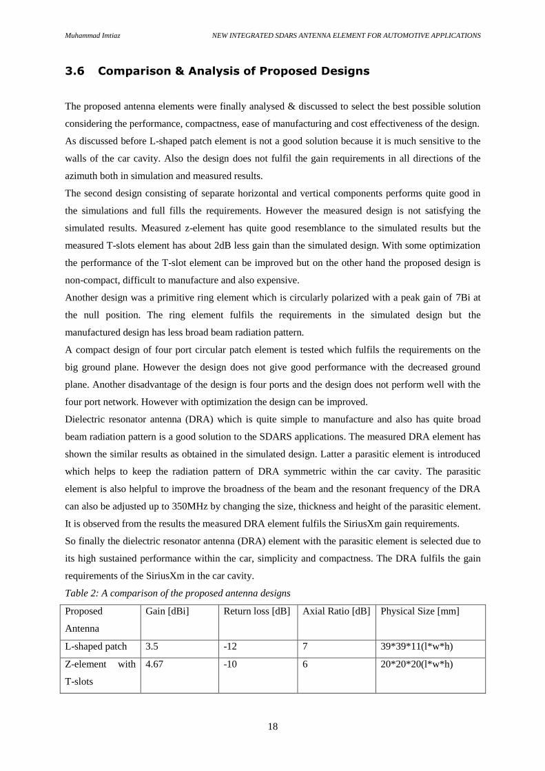
3.6 Comparison & Analysis of Proposed Designs
The proposed antenna elements were finally analysed & discussed to select the best possible solution
considering the performance, compactness, ease of manufacturing and cost effectiveness of the design.
As discussed before L-shaped patch element is not a good solution because it is much sensitive to the
walls of the car cavity. Also the design does not fulfil the gain requirements in all directions of the
azimuth both in simulation and measured results.
The second design consisting of separate horizontal and vertical components performs quite good in
the simulations and full fills the requirements. However the measured design is not satisfying the
simulated results. Measured z-element has quite good resemblance to the simulated results but the
measured T-slots element has about 2dB less gain than the simulated design. With some optimization
the performance of the T-slot element can be improved but on the other hand the proposed design is
non-compact, difficult to manufacture and also expensive.
Another design was a primitive ring element which is circularly polarized with a peak gain of 7Bi at
the null position. The ring element fulfils the requirements in the simulated design but the
manufactured design has less broad beam radiation pattern.
A compact design of four port circular patch element is tested which fulfils the requirements on the
big ground plane. However the design does not give good performance with the decreased ground
plane. Another disadvantage of the design is four ports and the design does not perform well with the
four port network. However with optimization the design can be improved.
Dielectric resonator antenna (DRA) which is quite simple to manufacture and also has quite broad
beam radiation pattern is a good solution to the SDARS applications. The measured DRA element has
shown the similar results as obtained in the simulated design. Latter a parasitic element is introduced
which helps to keep the radiation pattern of DRA symmetric within the car cavity. The parasitic
element is also helpful to improve the broadness of the beam and the resonant frequency of the DRA
can also be adjusted up to 350MHz by changing the size, thickness and height of the parasitic element.
It is observed from the results the measured DRA element fulfils the SiriusXm gain requirements.
So finally the dielectric resonator antenna (DRA) element with the parasitic element is selected due to
its high sustained performance within the car, simplicity and compactness. The DRA fulfils the gain
requirements of the SiriusXm in the car cavity.
Table 2: A comparison of the proposed antenna designs
Proposed
Antenna
Gain [dBi] Return loss [dB] Axial Ratio [dB] Physical Size [mm]
L-shaped patch 3.5 -12 7 39*39*11(l*w*h)
Z-element with
T-slots
4.67 -10 6 20*20*20(l*w*h)
Muhammad Imtiaz NEW INTEGRATED SDARS ANTENNA ELEMENT FOR AUTOMOTIVE APPLICATIONS
19
Ring 7 -14 4 36*9 (diameter*height)
Cicular patch 5.53 -5 6 40*3.5(diameter*height)
DRA 6.8 -33 Less than 3 26*10(diameter*height)
3.7 Results of Dielectric Resonator Antenna
The designed and measured results for the dielectric resonator antenna are presented in the following
subsections. Effect of the different parameters of DRA on the performance of DRA are presented and
discussed in detail here.
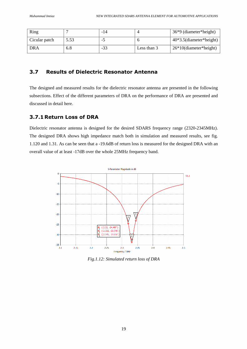
3.7.1 Return Loss of DRA
Dielectric resonator antenna is designed for the desired SDARS frequency range (2320-2345MHz).
The designed DRA shows high impedance match both in simulation and measured results, see fig.
1.120 and 1.31. As can be seen that a -19.6dB of return loss is measured for the designed DRA with an
overall value of at least -17dB over the whole 25MHz frequency band.
Fig.1.12: Simulated return loss of DRA
Muhammad Imtiaz NEW INTEGRATED SDARS ANTENNA ELEMENT FOR AUTOMOTIVE APPLICATIONS
20
Fig.1.13: Measured return loss of DRA
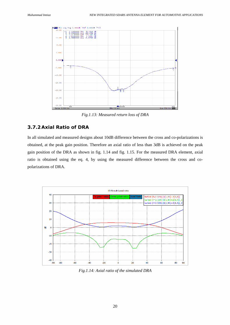
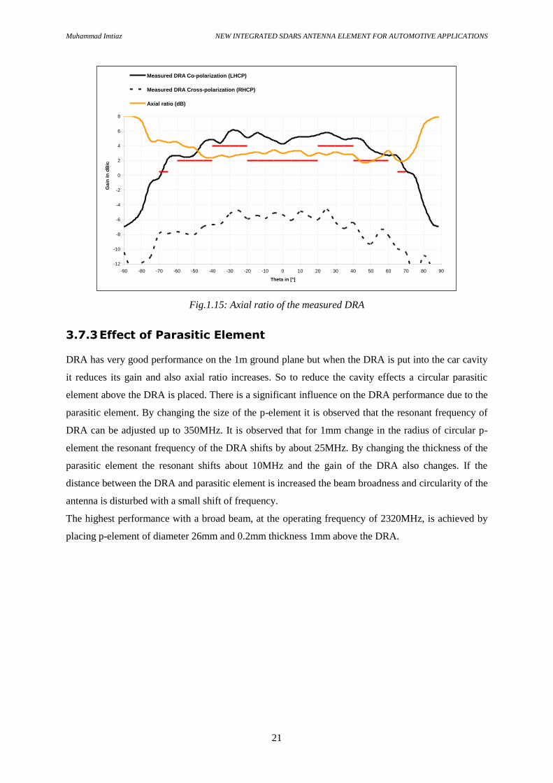
3.7.2 Axial Ratio of DRA
In all simulated and measured designs about 10dB difference between the cross and co-polarizations is
obtained, at the peak gain position. Therefore an axial ratio of less than 3dB is achieved on the peak
gain position of the DRA as shown in fig. 1.14 and fig. 1.15. For the measured DRA element, axial
ratio is obtained using the eq. 4, by using the measured difference between the cross and co-
polarizations of DRA.
Fig.1.14: Axial ratio of the simulated DRA
Muhammad Imtiaz NEW INTEGRATED SDARS ANTENNA ELEMENT FOR AUTOMOTIVE APPLICATIONS
21
Fig.1.15: Axial ratio of the measured DRA
3.7.3 Effect of Parasitic Element
DRA has very good performance on the 1m ground plane but when the DRA is put into the car cavity
it reduces its gain and also axial ratio increases. So to reduce the cavity effects a circular parasitic
element above the DRA is placed. There is a significant influence on the DRA performance due to the
parasitic element. By changing the size of the p-element it is observed that the resonant frequency of
DRA can be adjusted up to 350MHz. It is observed that for 1mm change in the radius of circular p-
element the resonant frequency of the DRA shifts by about 25MHz. By changing the thickness of the
parasitic element the resonant shifts about 10MHz and the gain of the DRA also changes. If the
distance between the DRA and parasitic element is increased the beam broadness and circularity of the
antenna is disturbed with a small shift of frequency.
The highest performance with a broad beam, at the operating frequency of 2320MHz, is achieved by
placing p-element of diameter 26mm and 0.2mm thickness 1mm above the DRA.
-12
-10
-8
-6
-4
-2
0
2
4
6
8
-90 -80 -70 -60 -50 -40 -30 -20 -10 0 10 20 30 40 50 60 70 80 90
Theta in [°]
Gain
In
dB
ic
Measured DRA Co-polarization (LHCP)
Measured DRA Cross-polarization (RHCP)
Axial ratio (dB)

Muhammad Imtiaz NEW INTEGRATED SDARS ANTENNA ELEMENT FOR AUTOMOTIVE APPLICATIONS
22
Fig.1.16: Measured effects of p-element on the DRA
3.7.4 Optimization of the DRA
The designed DRA element is optimized by changing all possible parameters. As the car cavity is very
small so all proposed elements had so much effect of the cavity walls and edges. For the DRA element
much less effects are observed and DRA sustained its good performance even in the cavity. It is
because of the strong concentrated fields around the DRA element. It is observed that the resonating
frequency of the DRA can be adjusted by changing the permittivity, height, diameter and the parasitic
element. There is not much effect on frequency due to the two feeding strips.
It is seen the DRA radiation pattern gets broader if the parasitic element is placed parallel to the car
cavity hole. Also the circularity of the DRA increases in this case.
The feeding network of the DRA gives the possibility to switch the polarity of the antenna from left
hand circular polarization to right hand circular polarization if the order of the phase shift between the
ports is changed. It is also observed that the axial ratio goes bad if the phase shift between the ports is
more or less than 90 degrees. Width of the feeding strips has minor effects on frequency shift and
radiation pattern of the DRA.
The dimensions of DRA have much effect on the gain, radiation pattern, circularity and impedance
matching of the developed antenna. It is observed that by increasing the height of the DRA element
from 8mm to 12mm, gain and broadness of the beam increases with a shift to lower frequency.
Increasing the height of the DRA also affects the circularity of the DRA element. If the radius of the
DRA is increased the overall gain of the element increases but due to the cavity wall effects the
circularity is not so good.
-12
-10
-8
-6
-4
-2
0
2
4
6
8
-90 -80 -70 -60 -50 -40 -30 -20 -10 0 10 20 30 40 50 60 70 80 90
Theta in [°]
Ga
in i
n [
dB
ic]
Average LHCP of reference antenna Average RHCP of reference antenna Average LHCP of DRA without p-element
Average RHCP of DRA without p-element Average LHCP of DRA with p-element Average RHCP of DRA with p-element

Muhammad Imtiaz NEW INTEGRATED SDARS ANTENNA ELEMENT FOR AUTOMOTIVE APPLICATIONS
23
3.8 DRA Simulation Results
The simulation results for the DRA element obtained using CST microwave studio are presented here.
As can be seen radiation pattern is quite broad with an axial ratio of less than 3 dB in the peak gain
directions. The DRA element is initially simulated on a 1m ground plane. As the results on the 1m
ground plane are very good so the DRA is simulated within the simple car cavity. Results obtained in
all three different car positions were simulated which are discussed below.
3.8.1 Roof Top Position
Initially the DRA element is simulated on 1m circular ground plane buried in a cavity with a tilt of 10
degree as shown in fig. 1.17. This is the most suitable position for the DRA with an available space of
50*50*20 and with no edges around the DRA element. In real life top roof position of the car has
more than 1m metal roof which serves as the ground plane for the DRA which further improves the
DRA performance.
The simulated results show the gain of 5.33dBi is achieved with a wide beam width. The difference
between the LHCP and RHCP of the DRA is more than 9 dB which gives an axial ratio of less than
3dB at the peak gain position.
Fig.1.17: Simulated design of the DRA in the top roof position

Muhammad Imtiaz NEW INTEGRATED SDARS ANTENNA ELEMENT FOR AUTOMOTIVE APPLICATIONS
24
Fig.1.18: Simulated co-polarization of the DRA in the top roof position
3.8.2 Windscreen Position
At the windscreen position the complete DRA element has the available space of 41*42*20 mm³. The
designed DRA element is buried in cavity as shown in fig. 1.19. The result obtained from the
simulated design is shown in fig. 1.20. Here it is required to hide the antenna within the cavity in such
a way that the antenna is not out of the cavity more than 2.5mm. At this position high gain of the
antenna is observed but the beam width decreases a little as compare to top roof position. It is due to
the near edges and the limited height available out of the cavity at this position. In the radiation pattern
cuts at different elevation angles shows the effect of the cavity wall and edges around the DRA
element.
Fig.1.19: Simulated design of the DRA in the windscreen position

Muhammad Imtiaz NEW INTEGRATED SDARS ANTENNA ELEMENT FOR AUTOMOTIVE APPLICATIONS
25
Fig.1.20: Simulated co-polarization of the DRA in the windscreen position
3.8.3 Spoiler Position
At the spoiler position the complete DRA element has the available space of 55*60*20 mm³. The
designed DRA element is place in spoiler with high edges of about 8mm around it as shown in fig.
1.21. The result obtained from the simulated design is shown in fig. 1.22. At this position good gain of
the antenna is observed but the beam width decreases a little as compare to top roof position. The
radiation pattern shows some cuts which are the effects of the side edges in the spoiler position.
Fig.1.21: Simulated design of the DRA in the spoiler position

Muhammad Imtiaz NEW INTEGRATED SDARS ANTENNA ELEMENT FOR AUTOMOTIVE APPLICATIONS
26
Fig.1.22: Simulated co-polarization of the DRA in the spoiler position
3.9 DRA Measurement Results
After successful simulation results of the DRA element a prototype is measured using vector network
analyser and MiDAS 4.1 for the far field radiation pattern measurements. The measured results are
similar to the simulated results. The developed SDARS antenna is tested for all three positions.
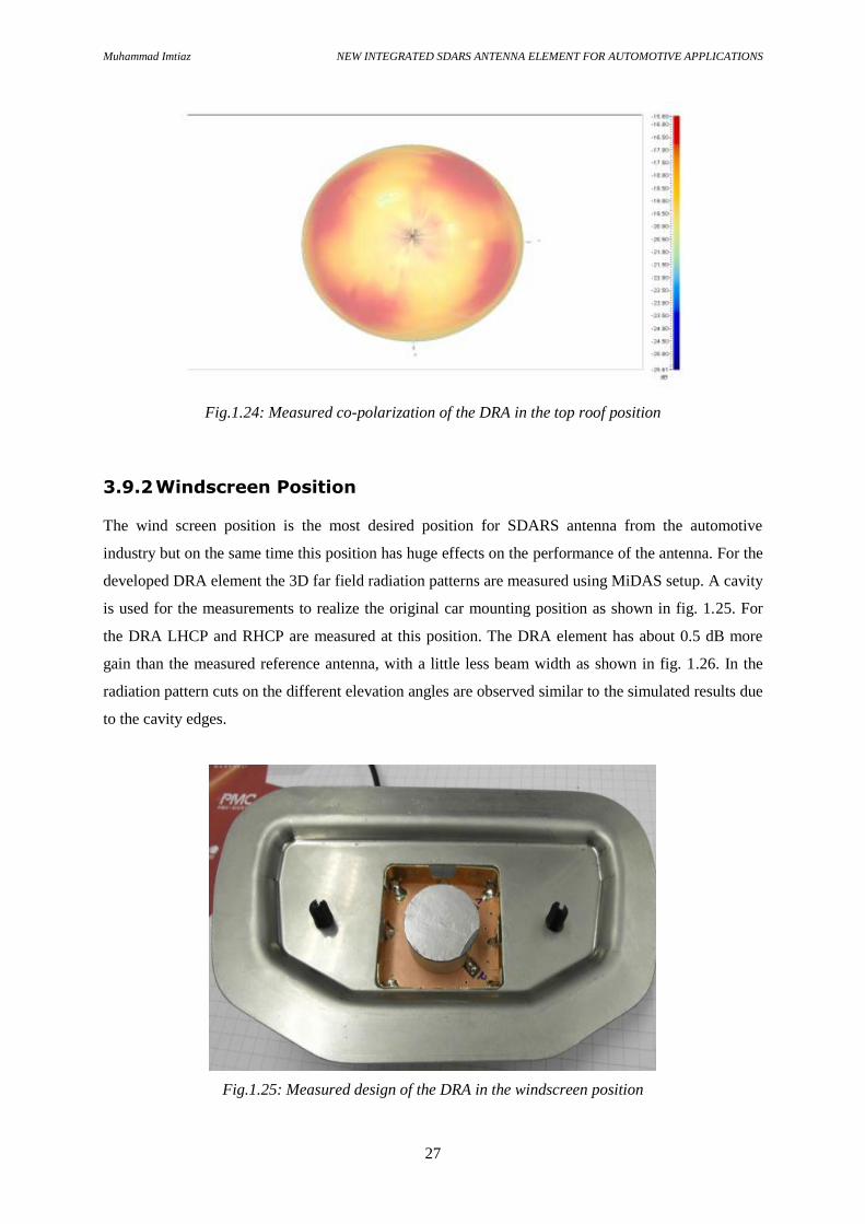
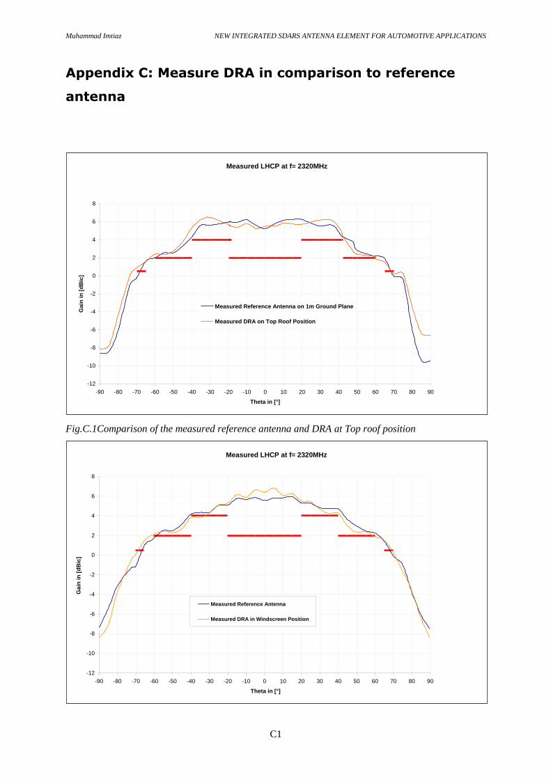
3.9.1 Roof Top Position
For the realization of the top roof position a circular ground plane of 1m diameter is used as shown in
fig. 1.23. The measured DRA element at this position shows very good performance with a high gain
at desired elevation angles as shown in fig. 1.24. Both LHCP and RHCP of the DRA are measured in
this position. An axial ratio of less than 2dB is observed at this position. It is observed that DRA
element has about 1.5 dB higher gain than the reference cross dipole antenna.
Fig.1.23: Measured design of the DRA in the top roof position
Muhammad Imtiaz NEW INTEGRATED SDARS ANTENNA ELEMENT FOR AUTOMOTIVE APPLICATIONS
27
Fig.1.24: Measured co-polarization of the DRA in the top roof position
3.9.2 Windscreen Position
The wind screen position is the most desired position for SDARS antenna from the automotive
industry but on the same time this position has huge effects on the performance of the antenna. For the
developed DRA element the 3D far field radiation patterns are measured using MiDAS setup. A cavity
is used for the measurements to realize the original car mounting position as shown in fig. 1.25. For
the DRA LHCP and RHCP are measured at this position. The DRA element has about 0.5 dB more
gain than the measured reference antenna, with a little less beam width as shown in fig. 1.26. In the
radiation pattern cuts on the different elevation angles are observed similar to the simulated results due
to the cavity edges.
Fig.1.25: Measured design of the DRA in the windscreen position

Muhammad Imtiaz NEW INTEGRATED SDARS ANTENNA ELEMENT FOR AUTOMOTIVE APPLICATIONS
28
Fig.1.26: Measured co-polarization of the DRA in the windscreen position
3.9.3 Spoiler Position
A spoiler of an old car is used in this measurement for the realization of the spoiler position as shown
in fig. 1.27. The measured DRA element at this position has a little less gain than the measured
reference antenna element as shown in fig. 1.28.
Fig.1.27: Measured design of the DRA in the spoiler position

Muhammad Imtiaz NEW INTEGRATED SDARS ANTENNA ELEMENT FOR AUTOMOTIVE APPLICATIONS
29
Fig.1.28: Measured co-polarization of the DRA in the spoiler position
Both LHCP and RHCP of the DRA are measured in this position. An axial ratio of less than 3dB is
observed at this position. It is observed that DRA element has about 1.5 dB lower gain than the
reference cross dipole antenna.
3.10 Discussion
Fig.1.29: Comparison of the measured co-polarizations of the DRA
Different designs were presented for the SDARS applications. All presented antennas show very good
performance on the ground plane without cavity. However it is observed that each of the presented
antenna elements have strong influence of the different car mounting positions. The presented antenna
Measured LHCP at f=2320MHz
-20
-15
-10
-5
0
5
10
0 10 20 30 40 50 60 70 80 90
Theta In [°]
Gai
n in
[d
Bic
]
DRA on Top Roof Position
DRA in Windscreen Position
DRA in Spoiler Position

Muhammad Imtiaz NEW INTEGRATED SDARS ANTENNA ELEMENT FOR AUTOMOTIVE APPLICATIONS
30
elements can be a good solution for the SDARS applications on a big ground plane such as top roof
position whereas for the use in the cavity and non-smooth ground planes, the antenna elements should
be optimized further. The newly developed DRA element for the SDARS application shows very good
performance. All simulated results were well verified by the measured results using MiDAS setup. A
high impedance match and less axial ratio is observed. The developed DRA performs best on the 1m
ground plane whereas it has some effects of the car cavity on the windscreen and spoiler position. It
can be seen that DRA element has high gain at the top roof and windscreen position. A comparison of
the DRA gain performance is shown in the fig. 1.29. It can be seen that the DRA element fulfils the
SiriusXm gain requirements of 4dBic at the top roof position and the windscreen positions. The DRA
performance degrades a little in the spoiler position due to the high edges and bends around the
antenna. Each position of the car has its own effects on the gain, operating frequency and circularity of
the antenna which needs to be optimized accordingly. Measured DRA is compared with a reference
circularly polarized cross dipole antenna. A comparison graph for all three possible positions is shown
in Appendix C. It can be seen that the DRA fulfils the SiriusXm gain requirements at the high
elevation angles. For the low elevation angles the element has little less gain but for satellite
communication gain at the high elevation angles specifically between 50 – 70 degrees must be
achieved. For the top roof and windscreen position DRA element has gain more than the reference
element.
Muhammad Imtiaz NEW INTEGRATED SDARS ANTENNA ELEMENT FOR AUTOMOTIVE APPLICATIONS
31
4 Conclusions and Future Work
This thesis work presents the research and development of the antenna element for the SDARS
applications. During the project work different designs were presented and it is observed that each
element has a strong influence of the car body on its performance. However the proposed designs can
be a good solution for the SDARS applications on a big ground plane such as top roof position
whereas for the use on a non-smooth ground planes the antenna elements should be optimized further.
Finally the newly developed DRA is presented which has a high gain of more than 6dBi with an axial
ratio of less than 3dB at the peak gain position. Return loss, less than -19dB is measured. The DRA
element shows best performance on the circular ground plane of 1m diameter. It is observed that the
DRA element has broad beam with high gain, if a parasitic element is used above the DRA. The
parasitic element helps to tune the resonating frequency of the DRA without changing the dimensions
of the DRA.
Rectangular or spherical shaped DRA elements can be optimized for this application resonating at
higher modes. It is also observed to have better response by placing the parasitic element directly on
the DRA which can be further investigated. All proposed designs can be optimized to improve their
performance on the non-smooth ground planes. Circular patch designs should be further optimized
with a better feeding network; z-element can be combined with another antenna element to give a
better theta element.

Muhammad Imtiaz NEW INTEGRATED SDARS ANTENNA ELEMENT FOR AUTOMOTIVE APPLICATIONS
32
References
[1] A. Petros, I. I. Zafar, S. Licul, “Reviewing SDARS antenna requirements”, Microwaves & RF,
2003, vol. 42, no9, pp. 51-62.
[2] C. McCarrick, "A Combination Monopole/Quadrifilar Helix Antenna for S-Band
Terrestrial/Satellite Applications", Microwave Journal, May 2001.
[3] H. Lindenmeier, J. Hopf, L. Reiter, “Low profile SDARS-Antenna with diversity Functionality”
IEEE Antennas and Propag. Symp.,vol. 4, pp. 744–747, 2002.
[4] D.-C. Chang, J.-H. Cheng, “2.3 GHz Antenna with both LHCP and LP for SDARS,” IEEE
Antennas and Propag. Symp.,vol. 3, pp. 874–877, June 2003.
[5] International Patent Classification H01Q 21/24, International Publication Number WO 01/80366
A1 - Applicant: Receptec L.L.C.
[6] A. Petros and S. Licul:, ““Folded” Quadrifilar Helix Antenna”. 2001 IEEE Antennas &
Propagation Society, International Symposium, Boston, July 8-13, 2001, 2001 Digest, Volume Four,
p. 569
[7] H.-G. Schuering, G.-H. Hassmann, H.K. Lindenmeier, L.M. Reiter, J.F. Hopf, S.M. Lindenmeier,
(Delphi Fuba Reception Syst.). “State of the art of vehicle antennas for satellite radio”. IEEE Antennas
and Propagation Society International Symposium, page(s): 68/71, vol. 1B, 2005.
[8] H. Man-Hoe; J Joo-Seong. "Microstrip patch antenna for SDARS reception". Antennas and
Propagation Society International Symposium, 2005, Page(s): 313 - 316 vol. 3B.
[9] P-S. Kildal and K. Rosengren, “Correlation and capacity of MIMO systems and mutual coupling,
radiation efficiency and diversity gain of antennas: simulations and Measurements in reverberation
chamber”, IEEE Communications Magazine, pp. 104-114, Vol.42, No. 12, Dec 2004.
[10] John D. Kraus, Antennas, second edition, McGraw-Hill, Inc. 1988
[11] David M. Pozar, Microwave Engineering, third edition, Jhon Wiley & Sons (Asia) Pte. Ltd., 1989

Muhammad Imtiaz NEW INTEGRATED SDARS ANTENNA ELEMENT FOR AUTOMOTIVE APPLICATIONS
33
[12] Constantine A. Balanis, Antenna Theory Analysis and Design, second edition, John Wiley &
Sons, Inc
[13] Computer code Computer Software Technology Microwave Studio, Available at
http://www.cst.de
[14] R. H. Rasshofer, M. Spies, and H. Spies, Advances in Radio Science, BMW Group Research and
Technology, Ingenieurb¨uro Spies, © Author(s) 2011. CC Attribution 3.0 License.
[15] K. Fujimoto, “Overview of antenna systems for mobile communications and prospects for the
future technology,” IEICE Trans. Commun., vol.E74-B, no.10, pp.3191-3201,Oct. 1991.
[16] K. Nishikawa, “Land vehicle antennas,” IEICE Trans. Commun., vol.E86-B, no.3, pp.993-1004,
Mar. 2003.
[17] ´´MiDAS User Manual´´, The ultimate in Microwave Measurement Software, by Orbit/FR, 2004.
[18] Massimo Pannozzo and Luca Salghetti Drioli, ´`State of the Art Review for Automotive Satellite
Antennas`´ 5th Advanced Satellite Multimedia Systems Conference and the 11th Signal Processing for
Space Communications Workshop, 2010.
[19] “XM Antenna Specification”, by XM Satellite Radio, Boca Raton, 2001.
[20] “Sirius-Antenna Specifications”, by Sirius Satellite, Radio, New York, 2001.
[21] Y.-P. Hong, J.-M. Kim, S.-C. Jeong, D.-H. Kim, abd J.-G. Yook, “Low-Profile S-Band Dual
Polarized Antenna for SDARS Application” IEEE Antennas and Wireless Propagation Letters, Vol. 4,
2005.

Muhammad Imtiaz NEW INTEGRATED SDARS ANTENNA ELEMENT FOR AUTOMOTIVE APPLICATIONS
A1
Appendix A: Measured reference antennas
Fig.A.1: Measured LHCP for cross dipole at 2.32GHz
Fig.A.2: Measured vertical component of quarter wave monopole at 2.32GHz

Muhammad Imtiaz NEW INTEGRATED SDARS ANTENNA ELEMENT FOR AUTOMOTIVE APPLICATIONS
B1
Appendix B: Measured proposed antennas
Fig.B.1: L-shaped patch measured design in windscreen car cavity
Muhammad Imtiaz NEW INTEGRATED SDARS ANTENNA ELEMENT FOR AUTOMOTIVE APPLICATIONS
B2
Fig.B.2: Measured Z-element design
Fig.B.3: Measured horizontal component of Z-element design
Fig.B.4: Measured T-slot element design
Measured Horizontal Component of Z-element
-12
-10
-8
-6
-4
-2
0
2
4
6
8
-90 -80 -70 -60 -50 -40 -30 -20 -10 0 10 20 30 40 50 60 70 80 90
Theta in [°]
Gain
in
[d
Bic
]
-175
-170
-165
-160
-155
-150
-145
-140
-135
-130
-125
-120
-115
-110
-105
-100
-95
-90
-85
-80
-75
-70
-65
-60
-55
-50
-45
-40
-35
-30
-25
-20
-15
-10
-5
0
average
min

Muhammad Imtiaz NEW INTEGRATED SDARS ANTENNA ELEMENT FOR AUTOMOTIVE APPLICATIONS
B3
Fig.B.5: Measured vertical component of T-slot element design
Fig.B.6: Measured ring antenna design
Measured Vertical Component of 4-Slot element
-12
-10
-8
-6
-4
-2
0
2
4
6
8
-90 -80 -70 -60 -50 -40 -30 -20 -10 0 10 20 30 40 50 60 70 80 90
Theta in [°]
Ga
in i
n [
dB
i]
-175
-170
-165
-160
-155
-150
-145
-140
-135
-130
-125
-120
-115
-110
-105
-100
-95
-90
-85
-80
-75
-70
-65
-60
-55
-50
-45
-40
-35
-30
-25
-20
-15
-10
-5
0
min
max
average
min
max

Muhammad Imtiaz NEW INTEGRATED SDARS ANTENNA ELEMENT FOR AUTOMOTIVE APPLICATIONS
B4
Fig.B.7: Measured co-polarization of the ring antenna at 2320MHz
Fig.B.8: Measured circular patch antenna design (a) top view (b) bottom view
Measured LHCP of Ring element in Cavity
-12
-10
-8
-6
-4
-2
0
2
4
6
8
-90 -80 -70 -60 -50 -40 -30 -20 -10 0 10 20 30 40 50 60 70 80 90
Theta in [°]
Ga
in i
n [
dB
ic]
-175
-170
-165
-160
-155
-150
-145
-140
-135
-130
-125
-120
-115
-110
-105
-100
-95
-90
-85
-80
-75
-70
-65
-60
-55
-50
-45
-40
-35
-30
-25
-20
-15
-10
-5
0
min
max
average
min
max
(a)
(b)
Muhammad Imtiaz NEW INTEGRATED SDARS ANTENNA ELEMENT FOR AUTOMOTIVE APPLICATIONS
B5
FigB.9: Measured co-polarization of the circular patch antenna
Measured LHCP for the Circular Patch Element at 2.325GHz
-12
-10
-8
-6
-4
-2
0
2
4
6
8
-90 -80 -70 -60 -50 -40 -30 -20 -10 0 10 20 30 40 50 60 70 80 90
Theta in [°]
Ga
in i
n d
Bic
,-175
-170
-165
-160
-155
-150
-145
-140
-135
-130
-125
-120
-115
-110
-105
-100
-95
-90
-85
-80
-75
-70
-65
-60
-55
-50
-45
-40
-35
-30
-25
-20
-15
-10
-5
0
average
min
Muhammad Imtiaz NEW INTEGRATED SDARS ANTENNA ELEMENT FOR AUTOMOTIVE APPLICATIONS
C1
Appendix C: Measure DRA in comparison to reference
antenna
Fig.C.1Comparison of the measured reference antenna and DRA at Top roof position
Measured LHCP at f= 2320MHz
-12
-10
-8
-6
-4
-2
0
2
4
6
8
-90 -80 -70 -60 -50 -40 -30 -20 -10 0 10 20 30 40 50 60 70 80 90
Theta in [°]
Ga
in i
n [
dB
ic]
Measured Reference Antenna on 1m Ground Plane
Measured DRA on Top Roof Position
Measured LHCP at f= 2320MHz
-12
-10
-8
-6
-4
-2
0
2
4
6
8
-90 -80 -70 -60 -50 -40 -30 -20 -10 0 10 20 30 40 50 60 70 80 90
Theta in [°]
Ga
in i
n [
dB
ic]
Measured Reference Antenna
Measured DRA in Windscreen Position

Muhammad Imtiaz NEW INTEGRATED SDARS ANTENNA ELEMENT FOR AUTOMOTIVE APPLICATIONS
C2
Fig.C.2: Comparison of the measured reference antenna and DRA at windscreen position
Fig.C.3: Comparison of the measured reference antenna and DRA at spoiler position
Measured LHCP at f= 2320MHz
-12
-10
-8
-6
-4
-2
0
2
4
6
8
-90 -80 -70 -60 -50 -40 -30 -20 -10 0 10 20 30 40 50 60 70 80 90
Theta in [°]
Ga
in i
n [
dB
ic]
Measured Reference Antenna on 1m Ground Plane
Measured DRA in Spoiler Position