STRUCTURAL INTEGRITY OF AN AGED OIL TANKER CONVERTED …
13
Nikola Vladimir Ivo Senjanović Neven Alujević Dae-Seung Cho Jose Luis Mantari Laureano https://doi.org/10.21278/TOF.4310 ISSN 1333-1124 eISSN 1849-1391 STRUCTURAL INTEGRITY OF AN AGED OIL TANKER CONVERTED INTO THE PORT OIL STORAGE Summary A procedure for strength assessment of a ship structure partially grounded in mud is developed. The paper deals with a practical engineering problem of evaluating the structural integrity of a single bottom tanker which, after its regular service, was grounded in mud and continued to be used as oil storage in order to increase the storage capacity of the port. A mathematical model of the ship static equilibrium is formulated, consistently taking into account the ship, the cargo and ballast weights, the supporting mud reaction, and the surrounding water buoyancy. For simplicity, the global strength assessment is done using the beam model, where the calculation of ship sectional properties is performed by the specialized in-house software. Subsequently, the developed model is used as a basis for a detailed 3D FEM analysis. The thickness measurements of the complete ship structure were performed in order to directly account for the corrosion effect. Key words: single hull oil tanker, oil storage, corrosion, structural analysis, FEM. 1. Introduction Demolition of aged ships is an important strategy for balancing the fleet capacity in the shipping sector [1]. As discussed by Yin and Fan [1], it is influenced by the ship obsolescence, technical developments, and environmental regulations on ship demolition, as well as by the state of the shipping market in general and by operating costs. A similar conclusion can also be drawn from the studies done by Stott [2] and Schøyen et al. [3]. Instead of submitting aged tankers to the usual recycling process, which is nowadays the subject of different policies [4], their hulls can sometimes be used to increase storage capacities in ports if this is economically justified [5]. However, one should take care about the ship hull integrity because of human safety during operation and potential environmental issues [6]. Generally speaking, a primary concern in the maritime sector is to enhance ship safety and to reduce marine pollution related to ship incidents and accidents [7]. In this process, the hull inspection is a very important task. Namely, it is well-known that corrosion affects both the local and the global ship strength so that a number of models have been TRANSACTIONS OF FAMENA XLIII-1 (2019) 65
Transcript of STRUCTURAL INTEGRITY OF AN AGED OIL TANKER CONVERTED …

Nikola Vladimir Ivo Senjanović Neven Alujević Dae-Seung Cho Jose Luis Mantari Laureano
https://doi.org/10.21278/TOF.43105 ISSN 1333-1124
eISSN 1849-1391
STRUCTURAL INTEGRITY OF AN AGED OIL TANKER CONVERTED INTO THE PORT OIL STORAGE
Summary
A procedure for strength assessment of a ship structure partially grounded in mud is developed. The paper deals with a practical engineering problem of evaluating the structural integrity of a single bottom tanker which, after its regular service, was grounded in mud and continued to be used as oil storage in order to increase the storage capacity of the port. A mathematical model of the ship static equilibrium is formulated, consistently taking into account the ship, the cargo and ballast weights, the supporting mud reaction, and the surrounding water buoyancy. For simplicity, the global strength assessment is done using the beam model, where the calculation of ship sectional properties is performed by the specialized in-house software. Subsequently, the developed model is used as a basis for a detailed 3D FEM analysis. The thickness measurements of the complete ship structure were performed in order to directly account for the corrosion effect.
Key words: single hull oil tanker, oil storage, corrosion, structural analysis, FEM.
1. Introduction
Demolition of aged ships is an important strategy for balancing the fleet capacity in the shipping sector [1]. As discussed by Yin and Fan [1], it is influenced by the ship obsolescence, technical developments, and environmental regulations on ship demolition, as well as by the state of the shipping market in general and by operating costs. A similar conclusion can also be drawn from the studies done by Stott [2] and Schøyen et al. [3]. Instead of submitting aged tankers to the usual recycling process, which is nowadays the subject of different policies [4], their hulls can sometimes be used to increase storage capacities in ports if this is economically justified [5]. However, one should take care about the ship hull integrity because of human safety during operation and potential environmental issues [6]. Generally speaking, a primary concern in the maritime sector is to enhance ship safety and to reduce marine pollution related to ship incidents and accidents [7]. In this process, the hull inspection is a very important task. Namely, it is well-known that corrosion affects both the local and the global ship strength so that a number of models have been
TRANSACTIONS OF FAMENA XLIII-1 (2019) 65

N. Vladimir, I. Senjanović, D.S. Cho, Structural Integrity of an Aged Oil Tanker N. Alujević, J.L. Mantari Laureano Converted Into the Port Oil Storage
developed in order to improve the structural analysis, inspection, and maintenance procedures as reported in [8,9,10,11]. Moreover, corrosion is one of the time-dependent detrimental phenomena which can lead to catastrophic failures [11,12,13].
This paper is focused on the practical problem of strength assessment of a grounded, aged, single-hull oil tanker, which is being used as the port oil storage. Namely, after its regular service, the ship was converted in such a way that its cargo area module is used as a stationary object with the aim of increasing the port storage capacities. The outline of a theoretical model with some selected 3D FEM results was presented in the conference paper [14]. The developed theoretical model is based on static equilibrium and geometric relations; in the model, the mud mass density is adjusted in order to properly take into account the sea bottom stiffness, i.e. the bottom reaction force. This is done because it was confirmed by observations that the exact ship position is independent of the loading condition variation. Therefore, it is reasonable to conclude that the mud reaction continuously changes depending on the cargo filling levels.
Although the developed theoretical procedure originates from a practical problem, it can be also useful for applications to similar problems such as, for instance, the salvage of ships in shallow waters. Although every grounding or stranding event is unique [15,16], in many cases, it is useful to know the exact value of contact force between the ship and the sea bottom [17], which can be precisely determined by the presented procedure.
2. Theoretical model
A single hull tanker vertically immersed in mud and surrounded by the sea water is presented in Fig. 1.
Fig. 1 Schematic diagram of the ship position [14]
The weight of the grounded ship is equilibrated partly by the buoyancy of water and partly by the sea bottom reaction. Hence, the total reaction R=F-B, as a difference between the ship weight, F, and the buoyancy, B, is known, but its distribution along the ship is not. In the proposed procedure it is assumed that the ship hull freely floats both in water and in mud, Fig. 2, [14].
The ship weight, F, has to be equilibrated by the buoyancy of the water and the mud, respectively:
0 0
d dL L
w w m mF g A x x g A x x , (1)
which gives:
w w m mF gV gV , (2)
where ρw and ρm denote the density of the water and the mud, respectively. In addition, Vw and Vm represent the volume of the ship immersed in the water and the mud, respectively, while Aw and Am denote the cross-section area immersed in the water and the mud, respectively. The gravity constant is denoted by g. From Eq. (2), one can calculate the mud density necessary to maintain the static equilibrium:
66 TRANSACTIONS OF FAMENA XLIII-1 (2019)

Structural Integrity of an Aged Oil Tanker N. Vladimir, I. Senjanović, D.S. Cho, Converted Into the Port Oil Storage N. Alujević, J.L. Mantari Laureano
w wm
m
F gVgV
. (3)
In the case of unit immersion of a ship, additional buoyancy represents the sea bottom (mud) stiffness, and yields:
m mk gB . (4)
where Bm is the cross-section breadth at the borderline between the mud and the water, Fig. 2.
Fig. 2 Cross-section of a ship immersed in the water and the mud [14]
2.1 Determination of the mud pressure The distribution of the mud reaction along the ship hull is shown in Fig. 3a. It can be
calculated by knowing the total weight of the ship and the cargo, F, and the longitudinal position of the centre of gravity (CG), xCG, which are regularly available from the loading manual.
Fig. 3 Mud reaction (a) and the mud pressure distribution (b) along the ship
According to Fig. 3a, the following expressions are obtained from the force and moment equilibrium:
21 2
1 1
21 l Fq ql l
, (5)
21 2 2 1 22 2
1 1
1 423 CG
lq q q l l Fxl l
, (6)
which leads to:
TRANSACTIONS OF FAMENA XLIII-1 (2019) 67

N. Vladimir, I. Senjanović, D.S. Cho, Structural Integrity of an Aged Oil Tanker N. Alujević, J.L. Mantari Laureano Converted Into the Port Oil Storage
2 21 2 2
1 1 1
1 41 2 13 CG
l lq q Fxl l l
. (7)
After substituting (5) into (7), one can write:
2 22
1 1 1 1
2 21 2 13
CGxl l Fql l l l
. (8)
Based on the above derivation, q2 and q1 can be expressed as:
1 1 22 1 2
1 12 2
1 1
2 2 12, 1
213
CGxFl l lFq q q
l ll ll l
. (9)
For the pressure calculation, the width of the mud waterline, BWLMUD, is relevant, Fig. 3a. According to Fig. 3b, one can write for the first, the second, and generally for the i-th tank area:
1 21 2, , i
iWLMUD WLMUD i
qq qp p pB B B
. (10)
2.2 An outline of the 1D FEM procedure For the 1D FEM analysis, an in-house code has been developed based on the
Timoshenko beam theory [18]; the analysis is performed by the finite element method [19,20]. The two-node finite element equation reads, [19,20]:
e eq b rF F K K , (11)
where {F} denotes the nodal force vector, and {δ} represents the vector of nodal displacements. The ordinary stiffness matrix for bending and shear from [19] is used, while the restoring matrix reads:
2
2 2 2 2
2 2 2 2 2
2 2
2 2
420 1 12
156 3528 20160 22 462 2520 54 1512 10080 13 378 2520
4 84 504 13 378 2520 3 84 504,
156 3528 20160 22 462 2520
. 4 84 504
r
klK
l l
l l l
l
Sym l
, (12)
where k represents the mud stiffness and 2/ sEI GA l . The buoyancy vector yields:
1 2
3 7 120 3 3 403 1 10 2 1 153 3 40 3 7 12060 1 12 60 1 122 1 15 3 1 10
e b
l lb l b lF
l l
, (13)
68 TRANSACTIONS OF FAMENA XLIII-1 (2019)

Structural Integrity of an Aged Oil Tanker N. Vladimir, I. Senjanović, D.S. Cho, Converted Into the Port Oil Storage N. Alujević, J.L. Mantari Laureano
where b1 and b2 represent the buoyancy values at the beginning and the end of FE, respectively. Similarly, for the weight vector with uniform weight distribution, one can write:
30 1 85 1 1230 1 860 1 125 1 12
e q
lqlF
l
. (14)
After acquiring the global stiffness, restoring matrices, and loading vectors, the hull deflection is obtained:
1
e er q bK K F F
. (15)
Finally, after determining the displacement vector , the nodal shear forces and bending moments can be obtained by returning to the finite element equation, Eq. (11).
3. Ship data, description of calculation setup and FEM models
3.1 Ship data The considered ship was built in 1956, with the tank layout shown in Fig. 4 and the
following main particulars: Length between perpendiculars: LPP = 149.07 m, Breadth: B = 25.72 m, Depth to the main deck: H = 14.1 m.
The central cargo tanks 4C-9C are intended to be used as the oil storage. The side tanks 1L, 1D, 4L, and 4D are to be empty, whereas the tanks 2L, 2D, 3L, 3D, 5L, 5D, 6L, and 6D contain permanent ballast, which together with the lightship mass, ensure a permanent contact between the ship structure and the bottom, [14].
Fig. 4 Ship arrangement with the disposition of tanks
(C – central tanks, L – port side tanks, D – starboard tanks)
Thickness measurement of the entire structure of the ship has been performed in order to accurately take into account the corrosion effect, i.e. to reliably simulate a realistic ship condition. For illustration, the arrangement of measurement points for the side tank plating is shown in Fig. 5. The ship is made of steel; for the purpose of calculation, the values of Young's modulus, material density, and Poisson's ratio are set at 2.1x10¹¹ N/m2, 7850 kg/m3, and 0.3, respectively.
TRANSACTIONS OF FAMENA XLIII-1 (2019) 69

N. Vladimir, I. Senjanović, D.S. Cho, Structural Integrity of an Aged Oil Tanker N. Alujević, J.L. Mantari Laureano Converted Into the Port Oil Storage
Fig. 5 Arrangement of measurement points for a side tank
3.2 Calculation setup For both the global and the local strength assessment, two sets of different
representative loading conditions are defined. For the global strength assessment, the ship is considered as a beam, and it is reasonable to assume that critical loading conditions are those representing a beam subjected to concentrated forces. In this sense, the loading conditions LC1 and LC2, Fig. 6a and 6b, are defined. Since the aims of the global and the local strength assessments are different, separate loading conditions should be considered in the 3D FEM analysis. In the local strength assessment, it is reasonable to assume that critical loading conditions are those causing maximum stresses in the transverse bulkheads, as shown in Fig. 6c and 6d.
Fig. 6 Schematic diagram of load cases
3.3 1D FEM model Stiffness parameters of the ship hull cross-section are determined using the strip
element method [21]; the software used here is the in-house software STIFF [22], Fig. 7.
70 TRANSACTIONS OF FAMENA XLIII-1 (2019)

Structural Integrity of an Aged Oil Tanker N. Vladimir, I. Senjanović, D.S. Cho, Converted Into the Port Oil Storage N. Alujević, J.L. Mantari Laureano
Fig. 7 Averaged thickness of plating at the midship section – STIFF software
The developed in-house code is used to determine global deflections of the ship structure supported by the mud and surrounded by the sea water. The beam model consists of 20 finite elements, where each tank is modelled with 2 finite elements. Longitudinal weight distributions for LC1 and LC2 are given in Fig. 8 and 9, respectively, where FE nodes along the ship are also marked.
Fig. 8 Longitudinal weight distribution for LC1 Fig. 9 Longitudinal weight distribution for LC2
3.4 3D FEM model A fine mesh 3D FEM model is generated in order to perform a detailed strength
assessment. The axonometric view on the FEM model is shown in Fig. 10. The complete FEM model was updated with ultrasonic gauging inspection data, as shown in the case of a typical cargo tank structure together with the side (ballast) tank structure, Fig. 11a, and the transverse bulkhead, Fig. 11b. Besides ordinary frames, the analysed ship structure is characterized by both semi-web frames, Fig. 12.
TRANSACTIONS OF FAMENA XLIII-1 (2019) 71

N. Vladimir, I. Senjanović, D.S. Cho, Structural Integrity of an Aged Oil Tanker N. Alujević, J.L. Mantari Laureano Converted Into the Port Oil Storage
Fig. 10 3D FEM model used in the structural analysis (view without the main deck structure)
Fig. 11 Typical cargo and ballast tank structure and transverse bulkhead with indicated plate thickness (mm)
Fig. 12 Typical web frames
4. Results
The FEM results obtained by the 1D FEM model are summarized in Fig. 13, where deflections along the ship are shown. For both LC1 and LC2, static deformations are almost negligible, confirming that the longitudinal strength is not an issue for a ship continuously supported by the mud. Some significant global deformations and consequently higher stresses can be expected only if the whole ship is moved from the existing equilibrium position, which cannot be achieved only by changing the amount of cargo.
72 TRANSACTIONS OF FAMENA XLIII-1 (2019)

Structural Integrity of an Aged Oil Tanker N. Vladimir, I. Senjanović, D.S. Cho, Converted Into the Port Oil Storage N. Alujević, J.L. Mantari Laureano
Fig. 13 Ship vertical deflections for LC1 and LC2
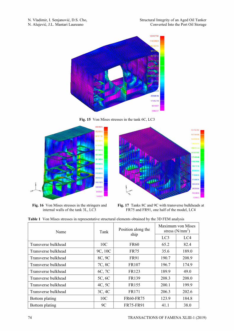
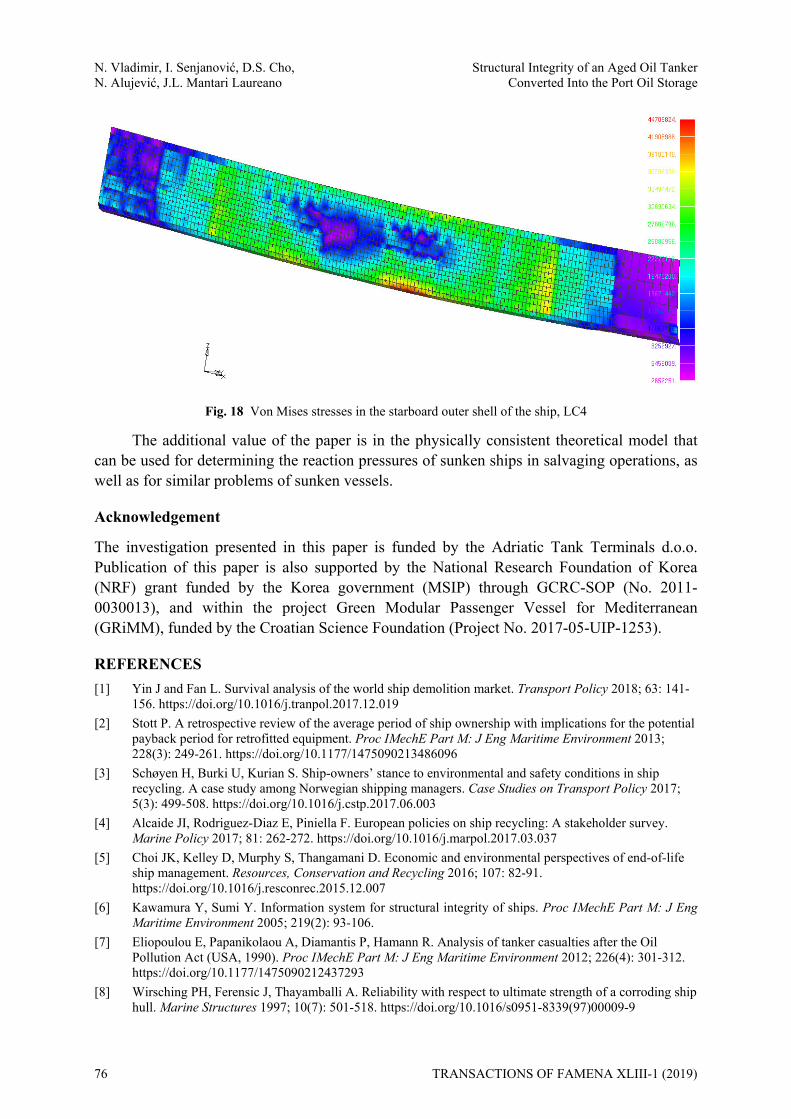
The 3D FEM static analysis is performed by the NASTRAN software [23] and the von Mises stresses are obtained for LC3 and LC4 in all structural elements, Table 1. The obtained stresses are compared with the maximum allowable stress which reads 230 N/mm2 [24]. Next, an overview of the results is given, where stress distributions are shown for characteristic structural members within the cargo area. Stress units in all figures are N/m2. Besides the von Mises stresses in the transverse bulkheads, Fig. 14a, shear stresses are also checked, Fig. 14b. A typical von Mises stress distribution in a cargo tank area is shown in Fig. 15. Fig. 16 shows the stress distribution in a typical ballast tank structure, while Fig. 17 shows characteristic structural elements with the highest stress levels for LC4 (transverse bulkhead at FR91). Finally, Figure 18 shows the von Mises stresses in the starboard outer shell of a ship.
Fig. 14 Stress levels in the transverse bulkhead at FR139, LC3; a) von Mises stresses, b) shear stresses
TRANSACTIONS OF FAMENA XLIII-1 (2019) 73
N. Vladimir, I. Senjanović, D.S. Cho, Structural Integrity of an Aged Oil Tanker N. Alujević, J.L. Mantari Laureano Converted Into the Port Oil Storage
Fig. 15 Von Mises stresses in the tank 6C, LC3
Fig. 16 Von Mises stresses in the stringers and internal walls of the tank 3L, LC3
Fig. 17 Tanks 8C and 9C with transverse bulkheads at FR75 and FR91, one half of the model, LC4
Table 1 Von Mises stresses in representative structural elements obtained by the 3D FEM analysis
Name Tank Position along the ship
Maximum von Mises stress (N/mm2)
LC3 LC4 Transverse bulkhead 10C FR60 65.2 82.4 Transverse bulkhead 9C, 10C FR75 35.6 189.0 Transverse bulkhead 8C, 9C FR91 190.7 208.9 Transverse bulkhead 7C, 8C FR107 196.7 174.9 Transverse bulkhead 6C, 7C FR123 189.9 49.0 Transverse bulkhead 5C, 6C FR139 208.3 208.0 Transverse bulkhead 4C, 5C FR155 200.1 199.9 Transverse bulkhead 3C, 4C FR171 206.3 202.6 Bottom plating 10C FR60-FR75 123.9 184.8 Bottom plating 9C FR75-FR91 41.1 38.0
74 TRANSACTIONS OF FAMENA XLIII-1 (2019)

Structural Integrity of an Aged Oil Tanker N. Vladimir, I. Senjanović, D.S. Cho, Converted Into the Port Oil Storage N. Alujević, J.L. Mantari Laureano
Name Tank Position along the ship
Maximum von Mises stress (N/mm2)
LC3 LC4 Bottom plating 8C FR91-FR107 36.2 57.4 Bottom plating 7C FR107-FR123 52.9 50.1 Bottom plating 6C FR123-FR139 41.0 59.3 Bottom plating 5C FR139-FR155 64.1 76.3 Bottom plating 4C FR155-FR171 45.5 57.9 Bottom plating 3C FR171-FR187 53.8 62.0 Tank internal structure 10C FR60-FR75 97.5 138.4 Tank internal structure 9C FR75-FR91 158.2 121.2 Tank internal structure 8C FR91-FR107 124.7 169.3 Tank internal structure 7C FR107-FR123 139.3 133.6 Tank internal structure 6C FR123-FR139 132.6 142.4 Tank internal structure 5C FR139-FR155 141.0 134.9 Tank internal structure 4C FR155-FR171 155.4 163.1 Tank internal structure 3C FR171-FR187 152.4 171.7 Longitudinal bulkhead, port side 10C FR60-FR75 42.0 64.4 Longitudinal bulkhead, port side 9C FR75-FR91 82.1 59.4 Longitudinal bulkhead, port side 8C FR91-FR107 61.2 82.2 Longitudinal bulkhead, port side 7C FR107-FR123 65.4 67.8 Longitudinal bulkhead, port side 6C FR123-FR139 53.7 64.8 Longitudinal bulkhead, port side 5C FR139-FR155 66.2 78.7 Longitudinal bulkhead, port side 4C FR155-FR171 52.6 59.8 Longitudinal bulkhead, port side 3C FR171-FR187 77.0 83.6
5. Conclusion
A procedure for assessing both the global and the local strength of the ship structure partially grounded in mud has been presented. It has been illustrated by a practical problem of strength assessment of an aged single hull tanker. The mud buoyancy is imposed as a hydrostatic pressure on the ship bottom. The analysis has been performed by 1D FEM and 3D FEM models. The global strength assessment performed by the 1D FEM model indicates that in this particular case there is practically no bending of the ship hull girder, meaning that the global stresses can be neglected. This is because the ship is supported by the mud and it remains the same in different loading conditions. The von Mises stresses and shear stresses are taken as the representative stresses for the evaluation of structural integrity in the 3D FEM analysis. Locations with the highest stress levels are identified for selected load cases. Despite the selection of the most unfavourable loading conditions, represented by different successive combinations of empty and full cargo tanks, the calculated stresses are below permissible values for all structural members. As expected, the maximum stress levels are regularly obtained in transverse bulkheads of the cargo (central) tanks.
TRANSACTIONS OF FAMENA XLIII-1 (2019) 75
N. Vladimir, I. Senjanović, D.S. Cho, Structural Integrity of an Aged Oil Tanker N. Alujević, J.L. Mantari Laureano Converted Into the Port Oil Storage
Fig. 18 Von Mises stresses in the starboard outer shell of the ship, LC4
The additional value of the paper is in the physically consistent theoretical model that can be used for determining the reaction pressures of sunken ships in salvaging operations, as well as for similar problems of sunken vessels.
Acknowledgement
The investigation presented in this paper is funded by the Adriatic Tank Terminals d.o.o. Publication of this paper is also supported by the National Research Foundation of Korea (NRF) grant funded by the Korea government (MSIP) through GCRC-SOP (No. 2011-0030013), and within the project Green Modular Passenger Vessel for Mediterranean (GRiMM), funded by the Croatian Science Foundation (Project No. 2017-05-UIP-1253).
REFERENCES [1] Yin J and Fan L. Survival analysis of the world ship demolition market. Transport Policy 2018; 63: 141-
156. https://doi.org/10.1016/j.tranpol.2017.12.019 [2] Stott P. A retrospective review of the average period of ship ownership with implications for the potential
payback period for retrofitted equipment. Proc IMechE Part M: J Eng Maritime Environment 2013; 228(3): 249-261. https://doi.org/10.1177/1475090213486096
[3] Schøyen H, Burki U, Kurian S. Ship-owners’ stance to environmental and safety conditions in ship recycling. A case study among Norwegian shipping managers. Case Studies on Transport Policy 2017; 5(3): 499-508. https://doi.org/10.1016/j.cstp.2017.06.003
[4] Alcaide JI, Rodriguez-Diaz E, Piniella F. European policies on ship recycling: A stakeholder survey. Marine Policy 2017; 81: 262-272. https://doi.org/10.1016/j.marpol.2017.03.037
[5] Choi JK, Kelley D, Murphy S, Thangamani D. Economic and environmental perspectives of end-of-life ship management. Resources, Conservation and Recycling 2016; 107: 82-91. https://doi.org/10.1016/j.resconrec.2015.12.007
[6] Kawamura Y, Sumi Y. Information system for structural integrity of ships. Proc IMechE Part M: J Eng Maritime Environment 2005; 219(2): 93-106.
[7] Eliopoulou E, Papanikolaou A, Diamantis P, Hamann R. Analysis of tanker casualties after the Oil Pollution Act (USA, 1990). Proc IMechE Part M: J Eng Maritime Environment 2012; 226(4): 301-312. https://doi.org/10.1177/1475090212437293
[8] Wirsching PH, Ferensic J, Thayamballi A. Reliability with respect to ultimate strength of a corroding ship hull. Marine Structures 1997; 10(7): 501-518. https://doi.org/10.1016/s0951-8339(97)00009-9
76 TRANSACTIONS OF FAMENA XLIII-1 (2019)

Structural Integrity of an Aged Oil Tanker N. Vladimir, I. Senjanović, D.S. Cho, Converted Into the Port Oil Storage N. Alujević, J.L. Mantari Laureano
[9] Saad-Eldeen S, Garbatov Y, Guedes Soares C. Strength assessment of a severely corroded box girder subjected to bending moment. J Constr Steel Res 2014; 92: 90-102. https://doi.org/10.1016/j.jcsr.2013.09.010
[10] Ventikos NP, Sotiralis P, Drakakis M. A dynamic model for the hull inspection of ships: The analysis and results. Ocean Eng 2018; 151: 355-365. https://doi.org/10.1016/j.oceaneng.2017.11.020
[11] Ivošević Š, Meštrović R, Kovač, N. Probabilistic estimates of corrosion rate of fuel tank structures of aging bulk carriers. Int J Nav Archit Ocean Eng 2018. https://doi.org/10.1016/j.ijnaoe.2018.03.003
[12] Paik JK, Thayamballi AK. Ultimate strength of ageing ships. Proc IMechE Part M: J Eng Maritime Environment 2002; 216(1): 57-77. https://doi.org/10.1243/147509002320382149
[13] Rahbar-Ranji A. Ultimate strength of corroded steel plates with irregular surfaces under in-plane compression. Ocean Eng 2012; 54: 261-269. https://doi.org/10.1016/j.oceaneng.2012.07.030
[14] Vladimir N, Senjanović I, Alujević N, Tomašević S, Cho DS. Strength assessment of an aged single hull tanker grounded in mud and used as port oil storage, Proceedings of the 4th International Conference on Maritime Technology and Engineering MARTECH 2018 – Progress in Maritime Engineering and Technology, Lisbon, Portugal, 2018; 345-356. https://doi.org/10.1201/9780429505294-40
[15] Mansour Youssef SA and Paik JK. Hazard identification and scenario selection of ship grounding accidents. Ocean Eng 2018; 153: 242-255. https://doi.org/10.1016/j.oceaneng.2018.01.110
[16] Gray W. Raising titans: How do you salvage a mega-ship?. New Scientist 2013; 220(2944): 48-51. https://doi.org/10.1016/s0262-4079(13)62748-7
[17] Lee CS, Yoon HS, Kim D, Na WB. Lifting forces required to salvage a sunken vessel and caisson and their response to bottom friction, buoyancy release, surface tension, water capture and water release. Ocean Eng 2016; 125: 82-89. https://doi.org/10.1016/j.oceaneng.2016.08.008
[18] Senjanović I and Vladimir N. Physical insight into Timoshenko beam theory and its modification with extension. Struct Eng Mech 2013; 48(4): 519-545. https://doi.org/10.12989/sem.2013.48.4.519
[19] Senjanović I, Tomašević S, Vladimir N. An advanced theory of thin-walled girders with application to ship vibrations. Mar Struct 2009; 22: 387-437. https://doi.org/10.1016/j.marstruc.2009.03.004
[20] Senjanović I. Finite element method in analysis of ship structures, University of Zagreb, Zagreb, 2002. (textbook, in Croatian).
[21] Cheung YK. Strip Method in Structural Analysis, Pergamon Press, 1976. [22] Fan Y and Senjanović I. STIFF, User's Manual, University of Zagreb, Faculty of Mechanical Engineering
and Naval Architecture, Zagreb, Croatia, 1990. [23] MSC. 2005. MSC.NASTRAN2005: Installation and Operations Guide, MSC Software. [24] CRS. 2016. Rules for Classification of Ships, Part 2 – Hull, Croatian Register of Shipping, Split, Croatia.
Submitted: 31.7.2018 Accepted: 10.12.2018
Nikola Vladimir Ivo Senjanović Neven Alujević Faculty of Mechanical Engineering and Naval Architecture, Ivana Lucica 5, 10000 Zagreb, Croatia, [email protected] Dae-Seung Cho Pusan National University, 63 beon-gil 2, Busandaehak-ro, Geumjeong-gu, Busan, 609-735, Korea Jose Luis Mantari Laureano Faculty of Mechanical Engineering, Universidad Nacional de Ingeniería (UNI), Avenida Tupac Amaru 210, Rimac, Lima, Peru, [email protected]
TRANSACTIONS OF FAMENA XLIII-1 (2019) 77