Structural Design Criteria -...
34
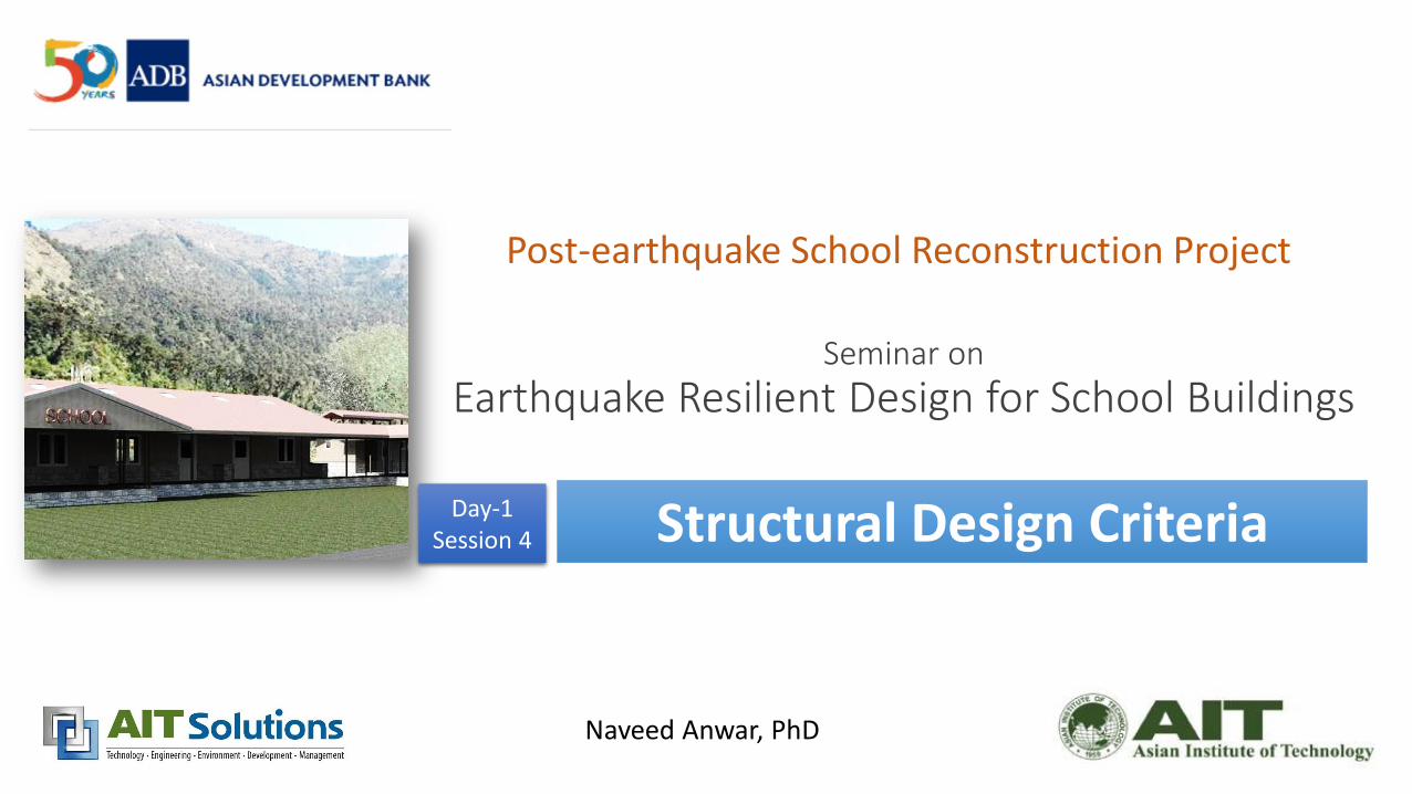
Seminar on Earthquake Resilient Design for School Buildings Naveed Anwar, PhD Post-earthquake School Reconstruction Project Structural Design Criteria Day-1 Session 4
Transcript of Structural Design Criteria -...
Seminar on
Earthquake Resilient Design for School Buildings
Naveed Anwar, PhD
Post-earthquake School Reconstruction Project
Structural Design Criteria Day-1Session 4

Structural Design Criteria Day : 1Session: 4

3
Document is Public
Now Available : doe.gov.np

4
Introduction
• After Gorkha Earthquake, The Government of Nepal (GON), and several development partners have developed a comprehensive Post Disaster Need Assessment (PDNA) document.
• One of the sector considered in the overall PDNA is Education, which identities the needs for rehabilitation and reconstruction of effected infrastructure for education sector, including the school buildings and facilities.
• As part of the rebuilding strategy, guidelines have been developed for the design of new schools.

5
Introduction
• This document presents the proposed design criteria and overall methodology to beused for the structural design of school buildings.
• This document has been prepared by the Asian Development Bank (ADB) and JapanInternational Cooperation Agency (JICA).
• The document is intended to be the official guidelines to the Department ofEducation (DOE), for structural aspects of planning and design of new schoolsconsistent with the Design Guidelines for Type Design of School Buildings which setsout architectural and planning requirements.
6
Scope and Purpose
• This document is intended to provide a unified and consistent criterion for carrying out detailed structural design of school buildings in Nepal, for resistance to the effects of earthquakes and other natural hazards.
• The document is particularly applicable to the Type Design of new school buildings for the post-earthquake reconstruction in the 14 most effected districts.
• The document may also be used for structural design of school buildings in general for all districts in Nepal, either in mountains, hills or plains.

7
Contents
• Introduction
• Design Philosophy and Approach
• Basic Materials
• Loads
• Structural Systems
• Code-based Design
• Seismic Performance-based Evaluation

8
Structural Systems
Sys-1: Ordinary reinforced concrete moment frame with unreinforced masonry infill wallsSys-2: Special steel moment resisting frameSys-3: Reinforced interlocking block bearing wall system (for example, Habitech system)Sys-4: Special reinforced concrete moment frameSys-5: Cold-formed steel ordinary moment frameSys-6: Hold-rolled steel ordinary moment frameSys-7: Timber structure

9
Two Design Approaches
Approach 1: Code based and Performance Based
Approach 2:Code based and optional verification
10
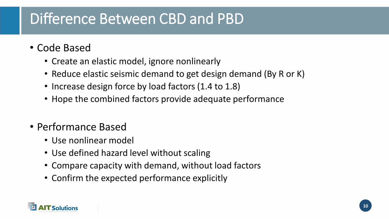
• Code Based• Create an elastic model, ignore nonlinearly
• Reduce elastic seismic demand to get design demand (By R or K)
• Increase design force by load factors (1.4 to 1.8)
• Hope the combined factors provide adequate performance
• Performance Based• Use nonlinear model
• Use defined hazard level without scaling
• Compare capacity with demand, without load factors
• Confirm the expected performance explicitly
Difference Between CBD and PBD

11
• The basis of Hazard levels in the Code are not clearly
• There are arbitrary factors in Codes (K and R) used to scale the elastic response
• The capacity and response of specific structural systems can be verified/confirmed using the code approach only
• Schools are for the future, and codes will be revised, greater reliability is required
• This criteria is for “Type Designs” to be used for large number of replications
Why Two Approaches
12
13
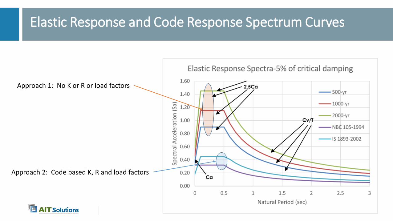
Elastic Response and Code Response Spectrum Curves
Approach 1: No K or R or load factors
Approach 2: Code based K, R and load factors
14
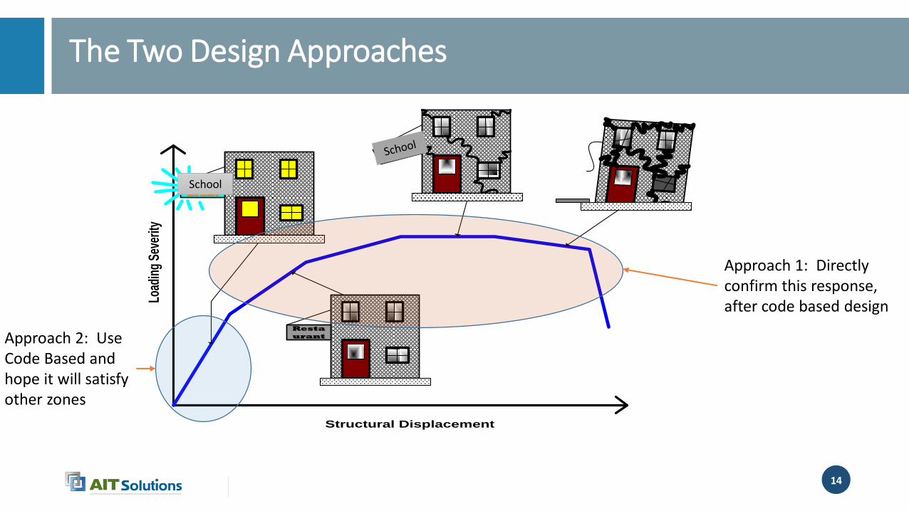
The Two Design Approaches
Structural Displacement
Load
ing
Seve
rity
Resta
urant
Resta
urant
Resta
urant
School
Approach 1: Directly confirm this response, after code based design
Approach 2: Use Code Based and hope it will satisfy other zones
15
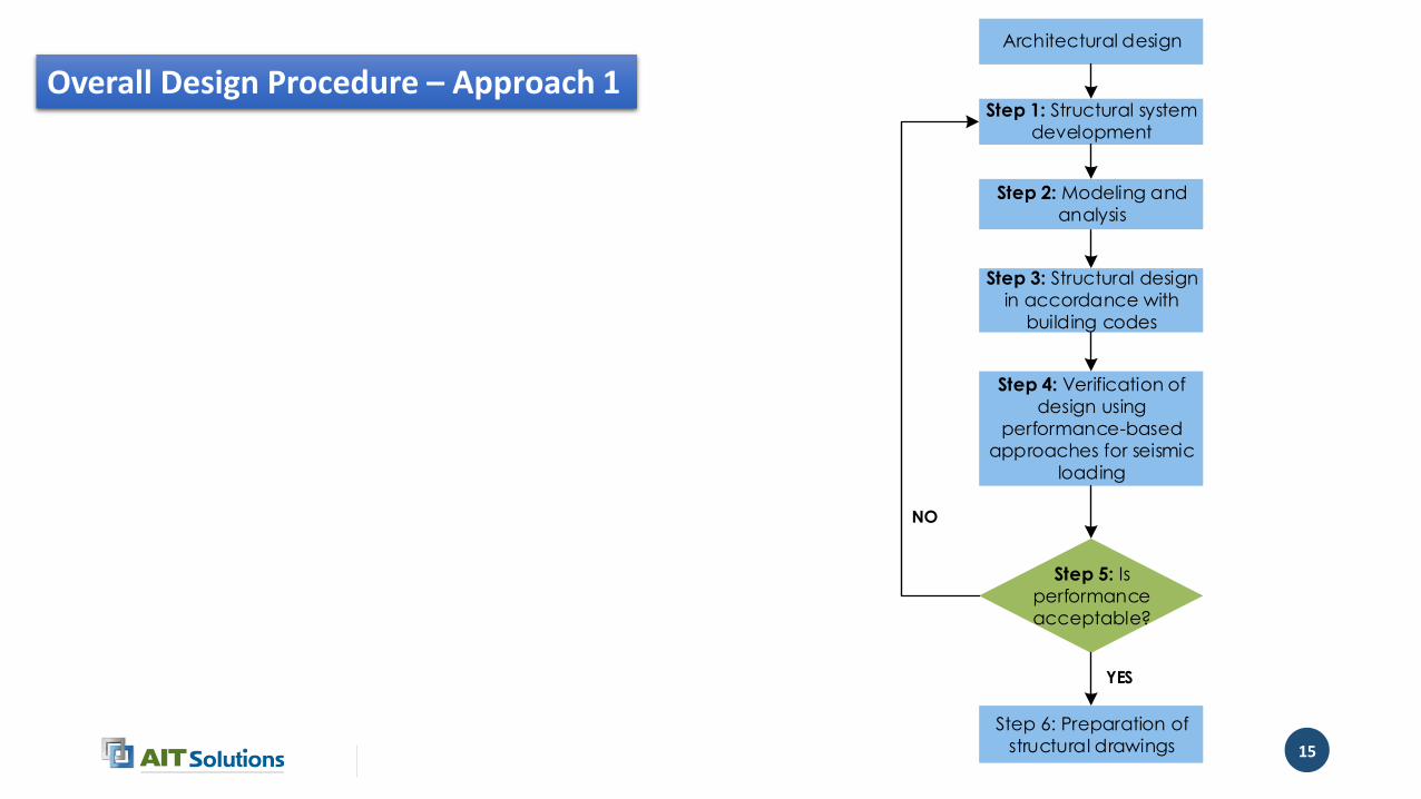
Architectural design
Step 1: Structural system
development
Step 2: Modeling and
analysis
Step 3: Structural design
in accordance with
building codes
Step 5: Is
performance
acceptable?
Step 4: Verification of
design using
performance-based
approaches for seismic
loading
Step 6: Preparation of
structural drawings
YES
NO
Overall Design Procedure – Approach 1
16
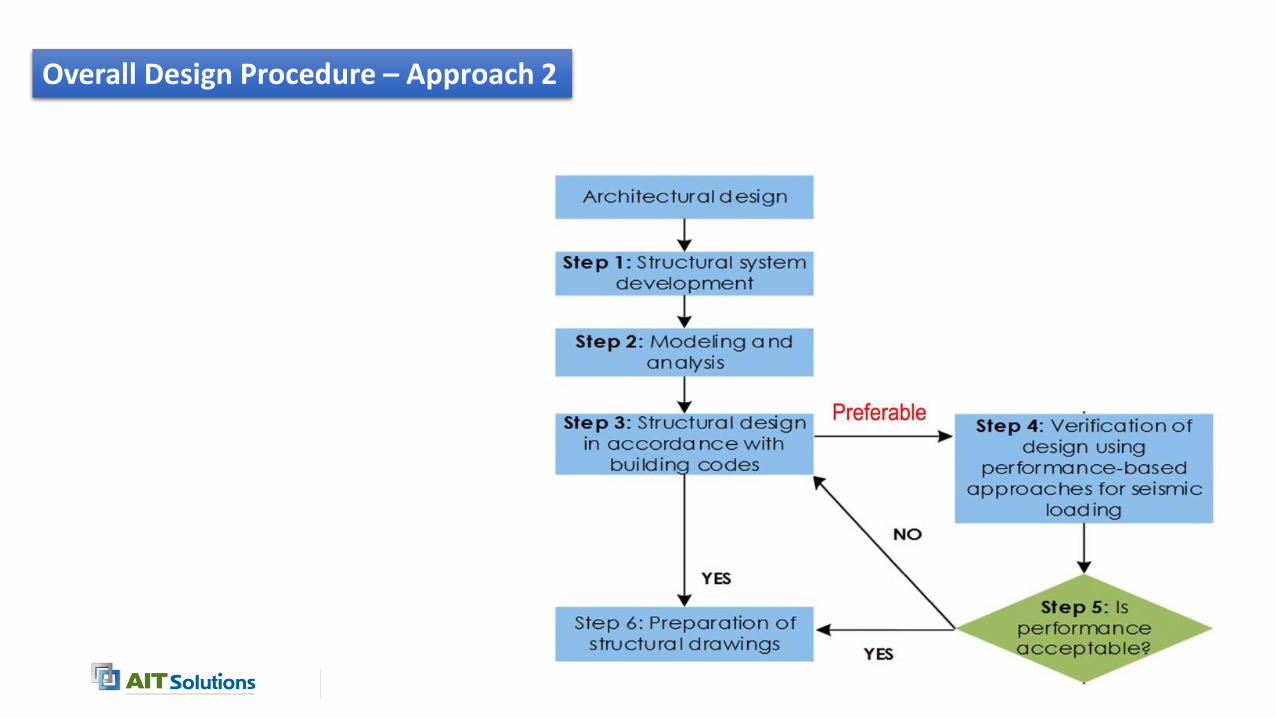
Overall Design Procedure – Approach 2
17
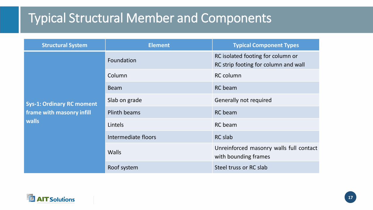
Typical Structural Member and Components
Structural System Element Typical Component Types
Sys-1: Ordinary RC moment
frame with masonry infill
walls
FoundationRC isolated footing for column or
RC strip footing for column and wall
Column RC column
Beam RC beam
Slab on grade Generally not required
Plinth beams RC beam
Lintels RC beam
Intermediate floors RC slab
WallsUnreinforced masonry walls full contact
with bounding frames
Roof system Steel truss or RC slab
18
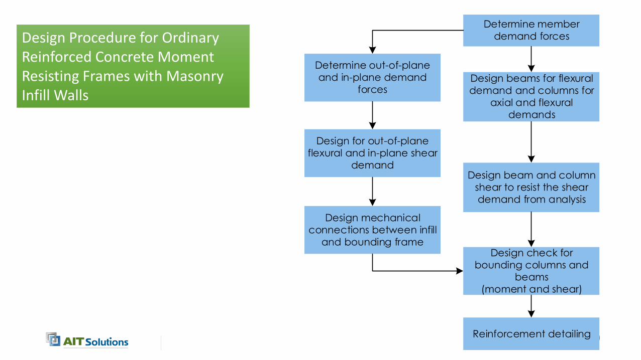
Determine member
demand forces
Design beams for flexural
demand and columns for
axial and flexural
demands
Design beam and column
shear to resist the shear
demand from analysis
Reinforcement detailing
Determine out-of-plane
and in-plane demand
forces
Design mechanical
connections between infill
and bounding frame
Design for out-of-plane
flexural and in-plane shear
demand
Design check for
bounding columns and
beams
(moment and shear)
Design Procedure for Ordinary Reinforced Concrete Moment Resisting Frames with Masonry Infill Walls
19
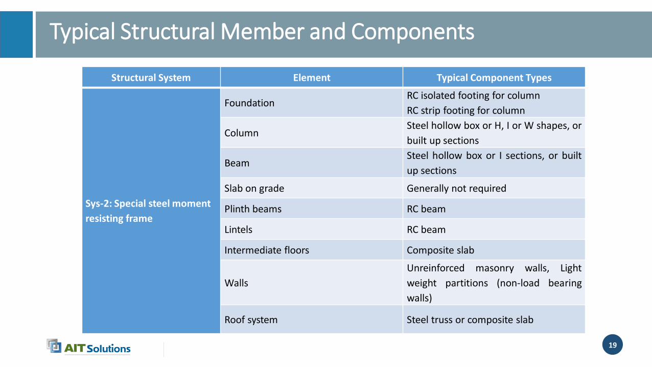
Typical Structural Member and Components
Structural System Element Typical Component Types
Sys-2: Special steel moment
resisting frame
FoundationRC isolated footing for column
RC strip footing for column
ColumnSteel hollow box or H, I or W shapes, or
built up sections
BeamSteel hollow box or I sections, or built
up sections
Slab on grade Generally not required
Plinth beams RC beam
Lintels RC beam
Intermediate floors Composite slab
Walls
Unreinforced masonry walls, Light
weight partitions (non-load bearing
walls)
Roof system Steel truss or composite slab
20
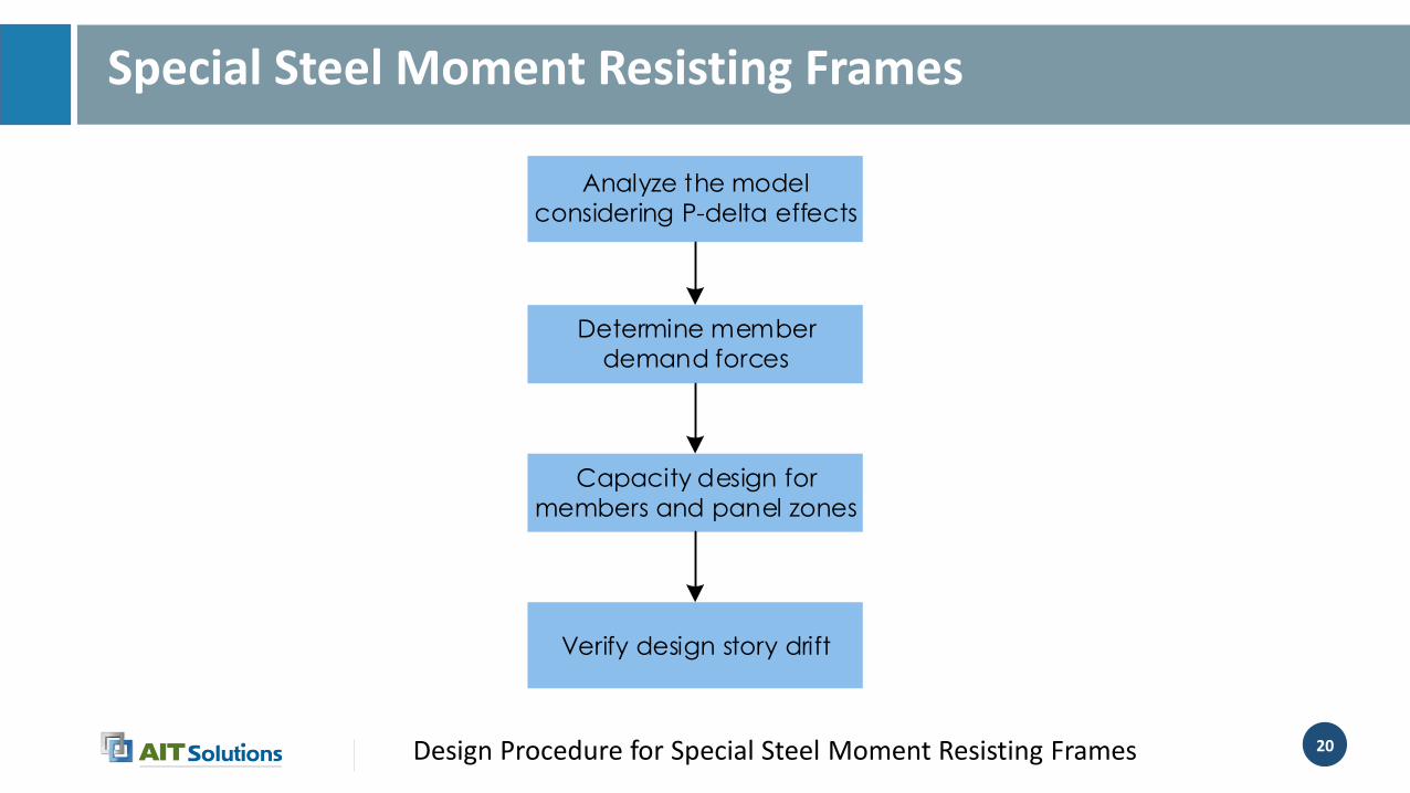
Special Steel Moment Resisting Frames
Determine member
demand forces
Capacity design for
members and panel zones
Verify design story drift
Analyze the model
considering P-delta effects
Design Procedure for Special Steel Moment Resisting Frames

21
Typical Structural Member and Components
Structural System Element Typical Component Types
Sys-3: Reinforced interlocking
bearing wall (Habitech
system)
Foundation
Brick or stone
RC strip footing for wall reinforced
stone masonry in C/C mortar
Bearing wallCompressed interlocking blocks,
reinforced with rebars
Slab on grade Generally not required
Plinth beams RC beam, blocks reinforced with rebars
Lintels RC beam, blocks reinforced with rebars
Intermediate floors RC slab, Habitech waist slab or similar
Roof system Steel truss or RC slab
22
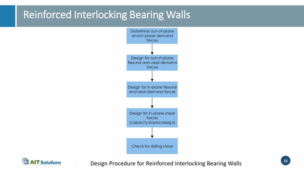
Reinforced Interlocking Bearing Walls
Determine out-of-plane
and in-plane demand
forces
Design for out-of-plane
flexural and axial demand
forces
Design for in-plane flexural
and axial demand forces
Design for in-plane shear
forces
(capacity-based design)
Check for sliding shear
Design Procedure for Reinforced Interlocking Bearing Walls

23
Typical Structural Member and Components
Structural System Element Typical Component Types
Sys-4: Special reinforced
concrete moment frame
FoundationRC isolated footing for column
RC strip footing for column
Column RC column
Beam RC beam
Slab on grade Generally not required
Plinth beams RC beam
Lintels RC beam
Intermediate floors RC slab
Walls
Unreinforced masonry walls, Light
weight partitions ( non-load bearing
walls)
Roof system Steel truss or RC slab

24
Reinforced Concrete Special Moment Resisting Frame
Determine member
demand forces
Design beams for flexural
demand and columns for
axial and flexural
demands
Design beam and column
shear based on capacity
based design procedures
Check for joint shear
Check strong column/
weak beam requirements
Reinforcement detailing
Design Procedure for Reinforced Concrete Special Moment Resisting Frame

25
Typical Structural Member and Components
Structural System Element Typical Component Types
Sys-5: Cold-formed steel
ordinary moment frame
FoundationRC isolated footing for column
RC strip footing for column
Column Cold-formed channel sections
Beam Cold-formed channel sections
Slab on grade Generally not required
Plinth beams RC beam
Lintels RC beam
Intermediate floors Not permitted.
Walls
Unreinforced masonry walls, Light
weight partitions ( non-load bearing
walls)
Roof system Cold-formed steel channel truss

26
Cold-formed steel ordinary moment resisting frames
• Cold-formed steel ordinary moment resisting frames shall be proportioned anddetailed in such a way that the frame will remain essentially elastic or design thehigher strength to reduce the high ductility demands under earthquakes.
• As the mass of structural system is small, the design will be primarily governedby wind loading.
27
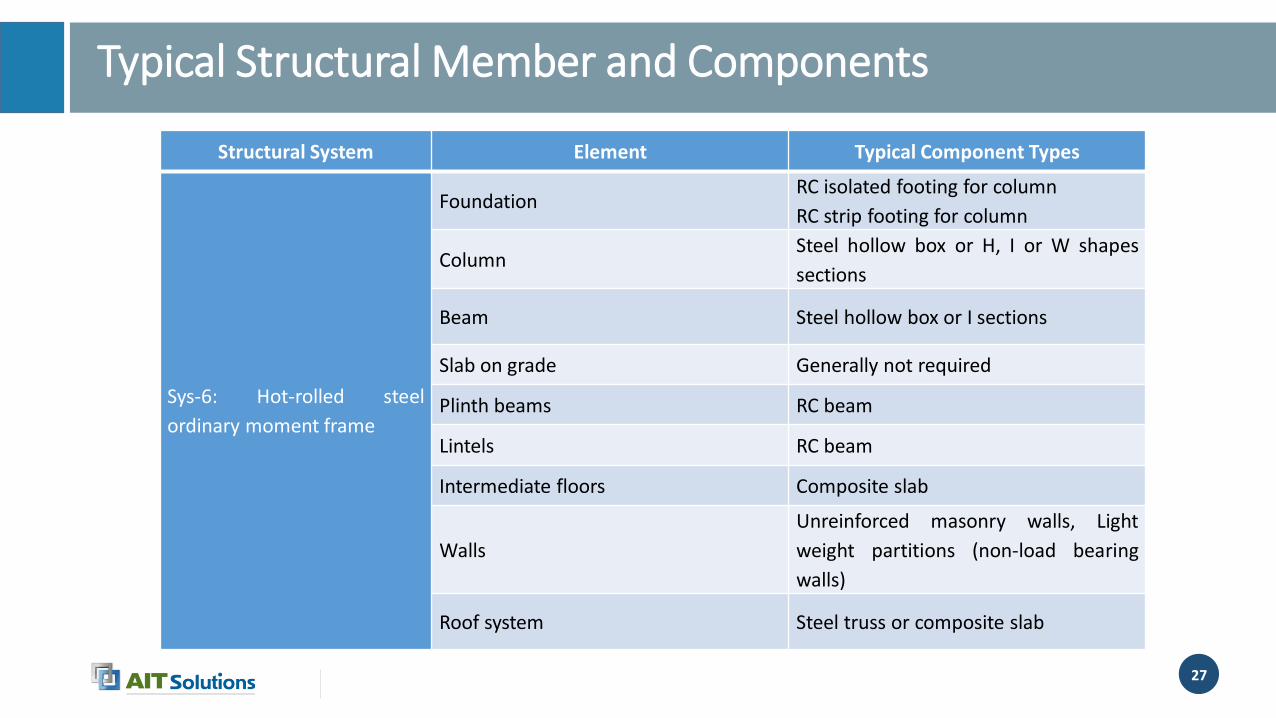
Typical Structural Member and Components
Structural System Element Typical Component Types
Sys-6: Hot-rolled steel
ordinary moment frame
FoundationRC isolated footing for column
RC strip footing for column
ColumnSteel hollow box or H, I or W shapes
sections
Beam Steel hollow box or I sections
Slab on grade Generally not required
Plinth beams RC beam
Lintels RC beam
Intermediate floors Composite slab
Walls
Unreinforced masonry walls, Light
weight partitions (non-load bearing
walls)
Roof system Steel truss or composite slab
28
Hot-rolled steel ordinary moment resisting frames
• Hot-rolled steel ordinary moment resisting frames shall be designed and detailed for higher strength to reduce the high ductility demands.

29
Typical Structural Member and Components
Structural System Element Typical Component Types
Sys-7: Timber structure
FoundationRC isolated footing for column
RC strip footing for column
Column Timber column
Beam Timber beam
Slab on grade Generally not required
Plinth beams RC beam
Intermediate floors Timber floor
Roof system Timber truss
30
Timber structure
• Wood-frame shear walls sheathed with shear panels of particle board, structural fiber board, and gypsum wall board are used to resist the seismic forces.
• Bearing wall system category would be applicable because shear walls used for seismic force resistance also function to support gravity loads of a building.
31
• Materials, loading and load combination should be according to code basedprovisions.
• Typical modeling, analysis and design procedure of structural systems are alsoexplained in document.
• Seismic performance-based evaluation of structural systems are also explained indocument.
32
References
• Structural design criteria for type design of school buildings, DOE, Nepal

33
Any Questions

34