IS 13551 (1992): Structural Design of Spillway Pier and ...Criteria for design of solid gravity dams...
13
Disclosure to Promote the Right To Information Whereas the Parliament of India has set out to provide a practical regime of right to information for citizens to secure access to information under the control of public authorities, in order to promote transparency and accountability in the working of every public authority, and whereas the attached publication of the Bureau of Indian Standards is of particular interest to the public, particularly disadvantaged communities and those engaged in the pursuit of education and knowledge, the attached public safety standard is made available to promote the timely dissemination of this information in an accurate manner to the public. इंटरनेट मानक “!ान $ एक न’ भारत का +नम-ण” Satyanarayan Gangaram Pitroda “Invent a New India Using Knowledge” “प0रा1 को छोड न’ 5 तरफ” Jawaharlal Nehru “Step Out From the Old to the New” “जान1 का अ+धकार, जी1 का अ+धकार” Mazdoor Kisan Shakti Sangathan “The Right to Information, The Right to Live” “!ान एक ऐसा खजाना > जो कभी च0राया नहB जा सकता ह ै” Bhartṛhari—Nītiśatakam “Knowledge is such a treasure which cannot be stolen” IS 13551 (1992): Structural Design of Spillway Pier and Crest - Criteria [WRD 9: Dams and Spillways]
Transcript of IS 13551 (1992): Structural Design of Spillway Pier and ...Criteria for design of solid gravity dams...

Disclosure to Promote the Right To Information
Whereas the Parliament of India has set out to provide a practical regime of right to information for citizens to secure access to information under the control of public authorities, in order to promote transparency and accountability in the working of every public authority, and whereas the attached publication of the Bureau of Indian Standards is of particular interest to the public, particularly disadvantaged communities and those engaged in the pursuit of education and knowledge, the attached public safety standard is made available to promote the timely dissemination of this information in an accurate manner to the public.
इंटरनेट मानक
“!ान $ एक न' भारत का +नम-ण”Satyanarayan Gangaram Pitroda
“Invent a New India Using Knowledge”
“प0रा1 को छोड न' 5 तरफ”Jawaharlal Nehru
“Step Out From the Old to the New”
“जान1 का अ+धकार, जी1 का अ+धकार”Mazdoor Kisan Shakti Sangathan
“The Right to Information, The Right to Live”
“!ान एक ऐसा खजाना > जो कभी च0राया नहB जा सकता है”Bhartṛhari—Nītiśatakam
“Knowledge is such a treasure which cannot be stolen”
“Invent a New India Using Knowledge”
है”ह”ह
IS 13551 (1992): Structural Design of Spillway Pier andCrest - Criteria [WRD 9: Dams and Spillways]

lndiun Standard
STRUCTURALDESTGNOFSPILLWAY PIER AND CREST-CRITERIA
UDC 627-83-066
@ BLS 1992
RUREAU OF INDIAN STANDARDS MANAK BHAVAN, 9 BAHADUK SHAH ZAFAR MARG
NEW DELHT 1102
December 1992 Price Group 3

Spillways Including Energy Dissipaters Sectional Committee, RVD 10
FOREWORD
This Indian Standard was Spillways Including Energy Division Council.
adopted by the Bureau of Indian Standards, after the draft finalized by t Dissipaters Sectional Committee had been approved by the River Valley
Spillway piers are erected over the crest profile and are provided to divide the spillway into number of bays so as to control the flow over the spillway by installing gates between two piers. Piers are also used to support the bridge over the spillway for the movement of gantry crane and normal traffic.
This standard is prepared to guide the designers, for the structural design of spillway pier and crest, based on the practices being followed in this country.
For the purpose of deciding whether a particular requirement of this standard is complied with, the final values, observed or calculated, expressing the results of a test or analysis, shall be rounded off in accordance with IS 2 : 1960 ‘Rules for rounding off numerical values ( revised)‘. The number of signi- ficant places retained in the rounded off value should be the same as that of the specified value in this standard.
IS 13551 : WE
Indian Standard
STRUCTURAL DESIGN OF SPILLWAY PIER AND CREST - CRITERIA
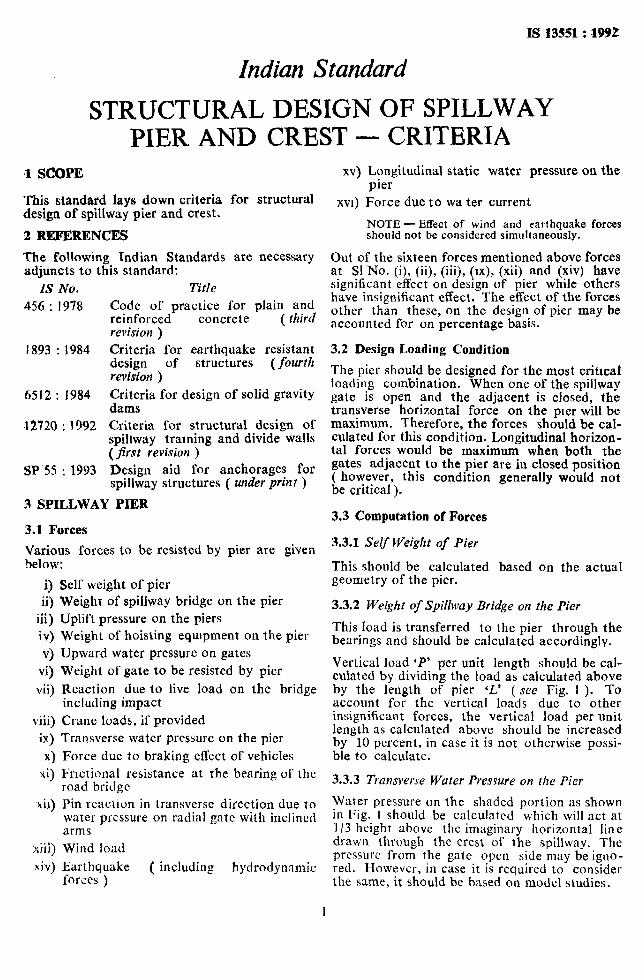
.l SCOPE
This standard lays down criteria for structural design of spillway pier and crest.
2 REFERENCES
The following Indian Standards are necessary adjuncts to this standard:
IS No.
456 : 1978
I 893 : 1984
6512 : 1984
,I2720 : 1992
SP 5s : 1993
Title
Code of practice for plain and reinforced concrete ( third revision )
Criteria for earthquake resistant design of structures (fourth revision )
Criteria for design of solid gravity dams Criteria for structural design of spillway training and divide walls (first revision )
Design aid for anchorages for spillway structures ( under print )
3 SPILLWAY PIER
3.1 Forces
;zarus forces to be resisted by pier are given
3 ii)
iii) iv)
v) vi)
vii)
viii) ix)
X) xi)
xii)
xiii)
.xiv)
Self weight of pier Weight of spillway bridge on the pier Uplift pressure on the piers Weight of hoisting equrpment on the pier Upward water pressure on gates Weight of gate to be resisted by pier
Reaction due to live load on the bridge including impact
Crane loads, if provided Transverse water pressure on the pier
Force due to braking effect of vehicles Frictional resistance at the bearing of the road bridge Pin reaction in transverse direction due to water pressure on radial gate with inclined arms
Wind load
Earthquake ( including hydrodynamic forces )
XV) Longitudinal static water pressure on the pier
XVI) Force due to wa ter current
NOTE -Effect of wind and earthquake forces should not be considered simultaneously.
Out of the sixteen forces mentioned above forces. at Sl No. (i), (ii), (iii), (lx), (xii) and (xiv) have significant effect on design of pier while others have insignificant effect. The effect of the forces other than these, on the design of pier may be accounted for on percentage basis.
3.2 Design Loading Condition
The pier should be designed for the most critical loading combination. When one of the spillway gate is open and the adjacent is closed, the transverse horizontal force on the pier will be maximum. Thereforr+.the forces should be cal- culated for this condrtton. Longitudinal horizon- tal forces would be maximum when both the gates adjacent to the pier are in closed position ( however, this condition generally would not be critical ).
3.3 Computation of Forces
3.3.1 Self Weight of Pier
This should be calculated based on the actua! geometry of the pier.
3.3.2 Weight of Spillway Bridge on the Pier
This load is transferred to the pier through the bearings and should be calculated accordingly.
Vertical load ‘P’ per unit length should be cal- culated by dividing the load as calculated above by the length of pier ‘L’ ( see Fig. 1 ). To account for the vertical loads due to other insignificant forces, the vertical load per unit length as calculated above should be increased by 10 percent, in case it is not otherwise possi- ble to calculate.
3.3.3 Tmnsverse Water Pressure on the Pier
Water pressure on the shaded portion as shown in Fig. I should be calculated which will act at l/3 height above the imaginary horizontal line drawn through the crest of the spillway. The prcssurc from the gate open side may be igno- red. However, in case it is required to consider the same, it should be based on model studies.
1

IS 13551 : 1992
3.3.4 Pin Reaction in Transverse Direction due to Water Pressure on Radial Gate with Inclined Arms
This is calculated for the condition when one gate is closed and the adjacent gate is open. This horizontal component of load (PT) in trans- verse direction at trunnion due to water pressure on the gate is given below:
P, = -J$ L tan 0
where w = unit weight of water
la - height of gate L = width of gate 0 = angle of inclination of arm with the
pier
3.3.5 Uplift Pressure on the Pie)
For planes below spillway crest level, the uplift pressure may be calculated according to 4.4.4.
For planes above spillway crest level, the uplift pressure may be calculated as given below:
4
b)
When the tail water level is below the spill- way crest level -’ Uplift pressure equal to the hydrostatic head over the plane under consideration may be taken to be acting uniformly over the full width of the pier up to a distance A ( see Fig. 1 ) and reduc- ing to zero at the intersection of the plane with the upper nappe profile.
When the tail water level is above the spill- way crest level - Uplift pressure equal to the hydrostatic head over the plane under consideration may be taken to be acting uniformly over the full width of the pier up to a distance A ( see Fig. 1 > and reduc- ing to the head corresponding to the tail water level at the downstream end of the pier.
Uplift pressure per unit length for zones 1 and 2 may be calculated by dividing the total uplift force in the zones under consideration by their respective lengths.
3.3.6 Earthquake
Earthquake forces ( including hydrodynamic forces ) should be calculated according to IS 1893 : 1984.
3.4 Design of Spillway Intermediate Pier
3.4.1 The entire pier should be divided into three zones ( see Fig. 2 ).
Zone I - Bending moment per unit length M,, is as given below:
M, M1= n_tB
where, M,, is moment due to the transver.;e water pressure about the imaginary horizontal line drawn through the crest of the spillway, and A and B are shown in Fig. 2. To account for the moments due to other insignificant forces, the moment per unit length calculated above should be increased by 20 percent in case it is not otherwise possible to calculate.
Zone 2 - Bending moment per unit length A[*,, is given below:
M, = MT + 0.35 Ml
where
MT = P.r x OT _. .--- L1
where, PT is horizontal component of loads Jt the trunnion due to water pressure tit the gate ( as calculated in 3.3.4 ). OT and L, are shown in Fig. 1.
AREA ON WHICH WATER PRESSURE ACTS FROM GATE CLOSED SIDE
SHORTEST DISTANCE
OF TRUNION FRqbi
ZONE 3
FIG. 1 WATER PRESSURB ACTING ON PIER
2
FIG. 2 ZONBS OF PIER
IS 13551 : l!m
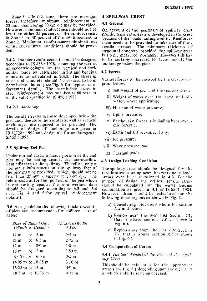
Zone 3 -. In this zone, there are no major forces, therefore minimum reinforcement of 25 mm diameter @ 30 cm c,‘c may be provided. However, minimum reinforcement should not be less than either 25 percent of the reinforcement in Zone 1 or 50 percent of the reinforcement in Zone 2. Maximum reinforcement obtained out of the above three conditions should be provi- ded.
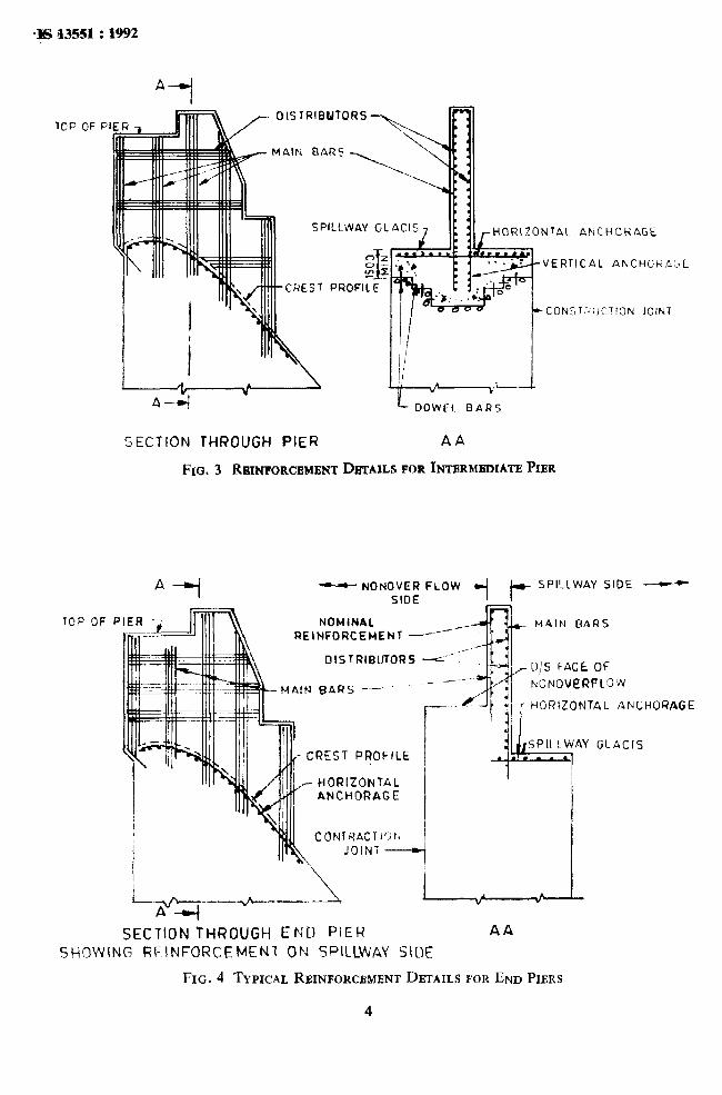
3.4.2 The pier reinforcement should be designed according to IS 456 : 1978, assuming the pier as an eccentric column for the vertical and hori- zontal loads as calculated in 3.3 and bending moments as calculated in 3.4.1. The stress in steel and concrete should be ensured to be in permissible limits ( see Fig. 3 for typical rein- forcement detail ). The permissible stress in steel reinforcement may be t.aken as 80 percent of the value specified in TS 456 : 1978.
3.4.2.1 Anchorage
The tensile stresses are also developed below the pier and, therefore, horizontal as well as vertical anchorages are required to be provided. The details of design of anchorage are given in IS 12720 : 1992 and design aid for anchorages in SP 55 : 1993.
3.5 Spillway Ead Pier
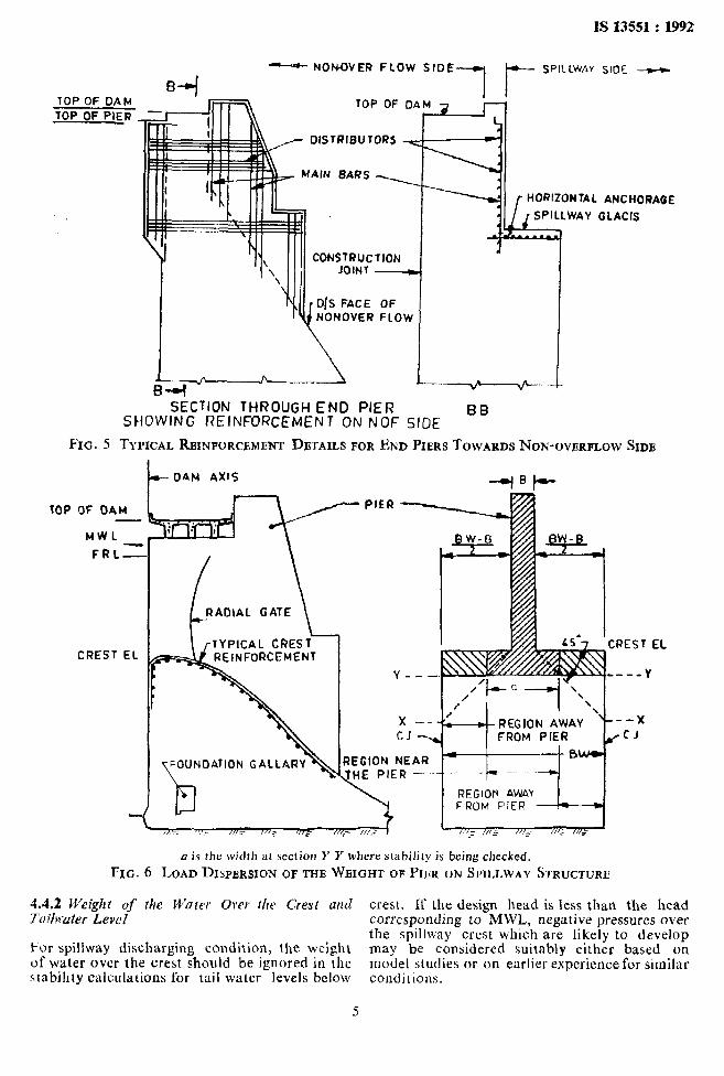
Under normal cases, a major portion of the end pier may be resting against the non-overflow dam adjacent to the spillway. Therefore, only a nominal reinforcement on the spillway face of the pier may be provided, which should not be less than 25 mm diameter @ 30 cm c/c, The reinforcement for the portion of the pier which is not resting against the non-overflow dam should be designed according to 3.3 and 3.4 ( see Fig. 4 and 5 for typical reinforcement details ).
3.6 As a guideline the following thickness/width of piers are recommended for different size of gates:
Sizes of Radial Gate T1~icknes.s~ Width ( Width x Height ) qf Pier
12 m x 5m 2.5 n-i
12 m x 6.5 m 2.75 m
12 in x 8.0 m 3*0 m
I5 m x I 2 111 3.50 III 9. I5 Ill x 64 111 2-5 m
14.95 ni x 10 GS m 3.50 m
lS*55 m x 14m 4.0 m 18,s III x J 6.75 m 4.75 m
4 SPILLWAY CREST
4.1 General
On account of the geometry of spillway cre:,t profile, tensile stresses are developed in the crest because of the loads acting over it. Reinforcc- ment needs to be provided to take care of these tensile stresses. The minimum thickness of structural concrete provided for spillway_erest is l-5 m, measured normally. However this has to be suitably increased to accommodate the anchorage below the piers.
4.2 Forces
Various forces to be resisted by the cresf are .!> given below:
0 ii)
iii)
iv)
v)
Self weight of pier and the spillway crert;
Weight of water over the crest and tail- water, where applicable;
Horizontal water pressure;
Uplift pressure;
Earthquake forces ( including hydrociyn;a- mic forces );
vi) Earth and silt pressure, if any;
vii) Ice pressure;
viii) Wave pressure; and
ix) Thermal loads.
4.3 Design Loading Condition
The spillway crest should be designed fJr ~he tensile stresses set up near the crest due to loads acting over it as mentioned in 4.2. For the purpose of design the critical tensile stres,, should be calculated for the worst loading combination as given in 4.1 of IS 6.512 : 1984. However, these should bc calculated for the following three regions as shown in Fig. 6.
a 1
b)
c>
Considering block RS a whole for se,tion XX and below.
Region near the pier ( At Scctiorl E-1, that is above section XX as chr\~n in Fig. 6 ).
Region away from the pier ( At Scctic-:I YY, that is above section XX as ihow; in Fig. 6 >,
4.4 Computation of Forces
This should be calculated for the appropr~at.: areas ( see Fig. 6 ) dependingupon the clc?,:tl I(*,$, at which stability is being checked.
3
WP OF P
TCP OF
SHOWI
fiik /-
OlSTRIBWTORS 1171
MAIN DAR’? -
SPILLWAY Gl
REST PRO!=11
HORIZONTAL ANCHORAGE
VERTICAL ANCHORA
CONST:‘!IIITION JOINT
‘JE
SECTION THROUGH PIER AA
FIG. 3 RBINPORCBMBNT DETAILS FOR INTBRMB~IATI3 PIER
*-I - NONOVER FLOW SIDE Lit--
SPILLWAY SIDE --
P NOMINAL REINFORCEMENT d
DISTRIBUTORS -I-
MAIt4 BARS - - - NONOWf?RFCo’fl
HORIZONTAL ANCHORAGE
CREST PROFILE
’ HORIZONTAL ANCHORAGE
I CO~TRnCrur;rl
JOINT
SECTION THROUGH END PIER AA
NG REINFORCEMENT ON SPICDVAY SIDE:
FIG. 4 TYPICAL RBINFORCBMENT DBTAILS FOR END PIERS
4
IS 13551 : 1992
TOP OF DAM TOP OF PIER
-- NONQVER FLOW SIDE L SPILLWAY SIOE ---tc
11
DISTRIBUTORs
CONSWUc JOINT
r D/S FACE
I :llON
-7 OF
HORUONUl ANCHORAGE
I_ _~ _~ I~VER FLOWI ; v^ (
SECTION THROUGH END PIER SHOWING REINFORCEMENT ON NOF SIDE
BB
FIG. 5 TYPZCAL RBINFORCGMENT DETAILS FOR END PIERS TOWARDS NON-OVERFLOW SIDE
I--- DAM AXIS
RAOIAL GATE
TYPICAL CREST REINFORCEMENT
REGlOfi AWAY FROM PIER --
a is the width at section Y Y where stability is being checked.
Fxc. 6 LOAD DI~PBRSION OF THE WEIGHT OF PIBR ON SPILLWAY STRUCTURE
4.42 Weight of the Water Over the Crest and Tdrafer Level
Fur spillway discharging condition, the weight of water over the crest should be ignored in the stabihty calculations for tail water levels below
5
crest. 1C the design head is less than the head corresponding to MWL, negative pressures ovel the spillway crest which are likely to develop may be considered suitably either based on model studies or on earlier experience for similar COnditions.

Is13551:1992
4.4.3 Horizorttal Water Pressure
The horizontal water pressure acting above spillway crest elevation in respect of gat;d spillway over the gates should be taken to be transferred to the pier at an appropriate eleva- tion depending on the type of gates used. For region away from the pier in respect of sections above XX (see Fig. 6 ) this force should not be considered.
4.4.4 Uplift Pressure
Uplift pressures should be considered to be acting over the spillway section only and not in the pier portion. For spillway discharging conditions and tail water levels, below the section at which stability is being checked, the effect of the sheet of water flowing over the spillway for uplift calculations may be ignored. For tailwater levels above the section consi- dered, uplift at the downstream end and the weight of water above crest should be suitably considered ( see Fig. 6 ).
4.4.5 The other forces mentioned in 4.2 ( v ) to ( ix ) should be computed as given in TS 65 12 : 1984.
I
4.5 Reinforcement
4.5.1 Spillway crest reinforcement should be calculated in respect of the tensile stress as cal- culated in 4.3. The crest reinforcement should be provided only if the tensile stresses exceed the allowable tensile stresses specified in 5.13.2.3 of JS 6512 : 1984.
4.5.2 The area of steel reinforcement should bc calculated in accordance with IS 456 : 1978. The permissible tensile stress in steel reinforcemenr may be taken as 80 percent of the value specified in IS 4.56 : 1978.
4.5.3 The reinforcement should be provided up 11) an elevation below which tensile stresses arc within permissible limits ( see 4.5.1 ). The deve- lopmcnt length below this elevation, however, hc provided according to 1s 456:: 1978.
45.4 Distribution reinforcement equal tc) WL less than 20 y0 of the main reinforcement should be provided. .Kowever, it should not be 1~~s th:?jl I6 mm diameter @ 25 cm c/c.
I i. ;
/ I
Standard Mark I The use of the Standard Mark is governed by the provisions of the Bureau of Indian
Standards Act, 1986 and the Rules and Regulations made thereunder. The Standard Mark on products covered by 8x1 Indian Standard conveys the assurance that they have been produced to comply with the requirements of that standard under a well defined system of inspection, testing and quality control which is devised and supervised by BIS and operated by the producer. Standard marked products are also continuously checked by BIS for con- formity to that standard as a further safeguard. Details of conditions under which a licence for the use of the Standard Mark may be granted to manufacturers or producers may be obtained from the Bureau of Indian Standards.

Bureau of Indian Standards
BLS is a statutory institution established under the Bureuu of Indian Standards Act, 1986 to harmonious development of the activities of standardization, marking and quality certification and attending to connected matters in the country.
Copyright
promote of goods
BIS has the copyright of all its publications. No part of these publications may be reproduced in any form without the prior permission in writing of BIS. This does not preclude the free use, in the course of implementing the standard, of necessary details, such as symbols and sizes, type or grade designations. Enquiries relating to copyright be addressed to the Director ( Publications ), BIS.
Revision of Indian Standards
Indian Standaras are reviewed periodically and revised, when necessary and amendments, if any, are issued from time to time. Users of Indian Standards should ascertain that they are in possession of the latest amendments or edition, Comments on this Indian Standard may be sent to BIS givmg the following reference:
Dot : No RVD 10 ( 4592 )
Amendments Issued Since Publication
Amend No. Date of lssue Text Affected
BUREAU OF INDIAN STANDARDS
Headquarters:
Manak Bhavan, 9 Bahadur Shah Zafar Marg, New Delhi 110002 Telephones : 331 01 31, 331 13 75
Regional Offices :
Central : Manak Bhavan, 9 Bahadur Shah Zafar Marg NEW DELHI 110002
Eastern : 1 14 C. I. T. Scheme VII M, V. I. P. Road, Maniktola c! ALCUTTA 700054
Northern : SC0 445-446, Sector 35-C, CHANDIGARH 160036
Southern : C. I. T. Campus, IV Cross Road, MADRAS 600113
Western : Manakalaya, E9 MIDC, Marol, Andheri ( East ) BOMBAY 400093
Telegrams : Manaksanstha ( Common to all offices )
Telephone
t
331 01 31 331 13 75
t
37 84 99, 37 85 61 37 86 26, 37 86 62
I
53 38 43, 53 16 40 53 23 84
{
235 02 16, 235 04 42 235 15 19, 235 23 15
632 92 95, 632 78 58 632 78 91, 632 78 92
Branches : AHMADABAD. ISANGALORE. RHOPAL. BHUBANESHWAR. COIMBATORE. FARTDABAD. GHAZIABAD. GUWAHATI. HYD.El<AI~Al~. JATPUR. KANPIJR. LUCKNOW. I’ATNA. ‘l-HIRlJVANANTIIAPIJRAM.