Structural Adaptive Façades Chloë Maryssecombining transformable structures with façade...
254
Structural Adaptive Façades Chloë Marysse Supervisor: Prof. dr. ir.-arch. Jan Belis Counsellor: Bert Van Lancker Master's dissertation submitted in order to obtain the academic degree of Master of Science in Civil Engineering Department of Structural Engineering Chair: Prof. dr. ir. Luc Taerwe Faculty of Engineering and Architecture Academic year 2015-2016
Transcript of Structural Adaptive Façades Chloë Maryssecombining transformable structures with façade...
Structural Adaptive Façades
Chloë Marysse
Supervisor: Prof. dr. ir.-arch. Jan Belis Counsellor: Bert Van Lancker Master's dissertation submitted in order to obtain the academic degree of
Master of Science in Civil Engineering
Department of Structural Engineering Chair: Prof. dr. ir. Luc Taerwe Faculty of Engineering and Architecture Academic year 2015-2016

ii
iii
Preface
The rapidly changing climate and the growing population present science and engineering major
challenges to save energy. A direct result is the increasing popularity of low-energy buildings during
the last decades. Buildings are responsible for a considerable part of the global energy consumption,
which explains this growing popularity. More sustainable designs may contribute to lower the negative
impact of buildings on the climate. Up till now, active technology was the most popular approach to
save energy in buildings. However, passive design strategies possess also fundamental advantages to
develop low-energy buildings. Efforts to lower the energy use by focusing on the construction and the
shape of a building have already resulted and will further result in promising energy efficient and
aesthetic applications.
By continuously changing their configuration, structural adaptive façades ensure a better building
performance. The flexibility in the systems allows to maintain a good performance over time by
anticipation and reaction. The façade is no longer seen as just a static barrier that separates the interior
building environment from the external one. In contrast, the façade becomes a dynamic playground
to optimise between energy objectives and occupants’ wishes. Clever and creative thinking and
designing allow to realise beautiful pieces of architecture that contribute to the lowering of the total
energy use of the building.

iv
v
Acknowledgements
During the year, I worked on the accomplishment of this thesis with a high interest and fascination for
the subject. At the realisation of this thesis many people, both directly and indirectly, contributed. I
would like to use this word of thanks for their support and dedication.
First of all, I want to thank my supervisor prof. dr. ir.-arch. Jan Belis to enable the creation of this thesis.
His support and professional help where of incredible importance to achieve this piece of work. His
critical look and helpful feedback made it able to work precisely and structured on the different parts.
He answered all my questions, both theoretical and practical, with experienced explanations that
contribute to a great extent to the final result. On the same time, he allowed an open approach and
personal interest, which enabled me to work with passion.
Secondly, I am grateful to Delphine Sonck, Jonas Dispersyn, Pieterjan Criel and Bert Van Lancker for
their expert knowledge on some specific parts. This knowledge was very useful and improved the
quality of the calculations. In this context, I also want to thank Sam Bouten for the sharing of his
experience with the drawing program Rhino and our constructive dialogues.
Finally, I am very thankful to my dad, Ferdy Marysse, for his continuous support and creative ideas. He
also took the time to read my thesis and to give helpful comments which had a final positive influence
to the end-result.

vi

vii
Permission for usage
“The author gives permission to make this master dissertation available for consultation and to copy
parts of this master dissertation for personal use. In the case of any other use, the limitations of the
copyright have to be respected, in particular with regard to the obligation to state expressly the source
when quoting results from this master dissertation.”
June 1, 2016
Chloë Marysse

viii
ix
Overview
Structural Adaptive Façades
By Chloë Marysse
Supervisor: Prof. dr. ir.-arch. Jan Belis
Counsellor: Bert Van Lancker
Master’s dissertation submitted in order to obtain the academic degree of
Master of Science in Civil Engineering
Department of Structural Engineering
Chair: Prof. dr. ir. Luc Taerwe
Faculty of Engineering and Architecture
Academic year 2015-2016
Summary
Structural adaptive façades are worldwide a rather unknown subject but in architectural surroundings
a lot of knowledge and structures are already available. Notwithstanding, most of this knowledge is
only applied on a small scale and for specific projects. A lot of opportunities exist to further broaden
this subject to a larger application scale and to develop new potential prototypes. The main aim of this
thesis is to provide insight in the application and design of structural adaptive façades, and to use this
knowledge in the development of innovative prototypes.
In the first part of the thesis, an extensive literature research is done to understand the possibilities of
combining transformable structures with façade applications. Research about the different types of
transformable structures is followed by the studying of façade structures. In a third part, both aspects
are integrated to obtain a clear view over the design of adaptive façades. During this research, several
case studies were analysed to gather knowledge about which current applications already exist and
which shortcomings offer opportunities for the design and improvement of future creations. These
case studies also provide a better understanding of the working principles of structural adaptive
façades.
The second part is focused on the design of new promising structural adaptive prototypes. A first
prototype faces the current energy problem with the emphasis on the intelligent application of
photovoltaic cells. The adaptability is used to provide both a higher energy efficiency and better
shading control. The design is characterised by its simplicity and functionality. A second prototype
approaches the balcony as a dynamic feature of a curtain wall façade. A double using principle arises
from the complete transformation between a balcony and a perforated screen. The design decreases
the primary energy use of the building by its positive influence on glare problems, overheating and
ventilation. The prototype facilitates an improved aesthetical appearance and allows more
architectural freedom. In addition, the prototype permits local control according to the users’ wishes.
Keywords
Sustainable building, transformable structure, adaptive façade, photovoltaics, dynamic balcony

x
xi
Structural Adaptive Façades
Chloë Marysse
Supervisor: Jan Belis
Counsellor: Bert Van Lancker
1
Abstract – This paper presents the implementation of
structural adaptive façades as a clever and aesthetic
solution to lower the energy footprint of a building. An
overall review of the current knowledge and applications
is given, followed by the design of two new adaptive
prototypes.
Keywords – Sustainable building, transformable
structure, adaptive façade, photovoltaics, dynamic
balcony
I. INTRODUCTION
The prevalent climate change faces science and
engineering with increased challenges to save energy.
Buildings are responsible for approximately one third
of the world’s energy use, which makes them an
attractive area to concentrate on. More sustainable
building designs may contribute to lower the negative
impact of buildings’ energy consumption on the
vulnerable climate.
Triggered by the need for more low-energy buildings,
structural adaptive façades win in recognition as they
present aesthetic and economic solutions. These
flexible systems break with the traditional use of the
façade as a static barrier that separates the internal and
external environment. In contrast, the façade becomes
a dynamic playground to make a compromise between
energy objectives and occupants’ wishes.
The subject of structural adaptive façades is - apart
from in architectural surroundings - not widely known.
Most of the knowledge is applied on specific and
unique projects. A lot of opportunities exist to improve
future designs and to broaden this branch of
architecture to a larger application scale.
II. LITERATURE REVIEW
A good understanding of the current knowledge
about structural adaptive façades is essential to
understand the present shortcomings and/or
opportunities to develop new innovative adaptive
solutions. The literature review concentrates on the
different types of transformable structures and the
contemporary knowledge about advanced building
1 C. Marysse is with the Department of Civil Engineering, Ghent
University (UGent), Gent, Belgium. E-mail: [email protected] .
façades. Both aspects are integrated to obtain a clear
view on the design of adaptive façades.
Transformable structures
Adaption and reaction to changing circumstances are
only possible with the application of transformable
structures. Therefore, a clever designed deployment
system, based on controlled movement, is necessary. A
wide range of possibilities exists to create these
structures. However, not all systems are suited for
façades. For building purposes, lattice structures
combined with flexible membranes or rigid plates can
provide stable and lightweight solutions. A good
consideration of the used actuators and locking systems
is important to make a fluent deployment possible.
Building façades
More sustainable buildings originate from the use of
advanced façades accommodated with a lower total life
cycle cost, decreased environmental impact and
increased internal comfort. The façade, as the envelope
of the building, permits to lower the impact of
environmental changes in an effective way.
Two major types of façades exist: curtain walls and
double façades. Both can contribute to a more optimal
thermal comfort. Curtain walls have high qualities in
influencing daylight control and energy gain. The
strong aspects of double façades are the capacity for
natural ventilation and acoustic control. Double façades
have the disadvantage of higher costs and a higher loss
of useful building space. A curtain wall is better suited
for the high position of the sun on the south façade, due
to its potential for horizontal shading systems. In
contrast, the double façade is more appropriate for the
east and west façade, because the lower position of the
sun requires vertical shading systems.
The higher initial cost, required for the construction
of these façades, is compensated by the lower energy
use of the building during its life cycle. A current
shortcoming of most façade applications is the strict
focus on only one (or two) comfort increasing
parameters, mostly solar control. A higher influence on
the energy balance may be achieved by concentrating
on different building physics integrated in one clever
design.
xii
Different geographical locations have different
climate characteristics and other primary requirements.
Adaptive systems are most suited for the moderate
climate zone, as a consequence of the seasonal variation
between the need for heating and the protection against
overheating. In addition, adaptive systems can be
efficient for (sub)tropical zones as well by providing
solar shading and natural ventilation. In contrast, cold
and polar zones require less adaptivity due to their
primary need for solar heating.
Adaptive façades
An envelope that uses flexibility to actively regulate
the indoor conditions, is one of the effective solutions
to increase the energy efficiency of a building. In this
line, adaptive systems with a mechanic based
movement principle hold endless possibilities.
Rotational, translational and even hybrid systems are
possible. Extrinsic control of these adaptive systems
possesses the quality to combine (central) automated
strategies with local control and individual user needs.
The domain of adaptive façades is far from saturated
and mature. Most current adaptive systems focus on
thermal and/or optical aspects. The amount of
applications that focus on the domain of energy gain is
rather small. This offers considerable opportunities for
the development of new promising photovoltaic
building applications. The biggest challenge is to make
the systems cost efficient and to combine creativity
with simplicity and standardisation to facilitate their
design.
III. CREATING NEW PROTOTYPES
Based on the knowledge acquired during the
literature review, the noticed shortcomings and their
opportunities are used to elaborate two designs of
prototypes with a future potential.
Prototype I: A photovoltaic solar shade system
Structural adaptive façades that emphasise the smart
application of photovoltaic cells in building façades are
currently present to a lesser extent. However, these
cells possess the quality to improve the overall building
performance.
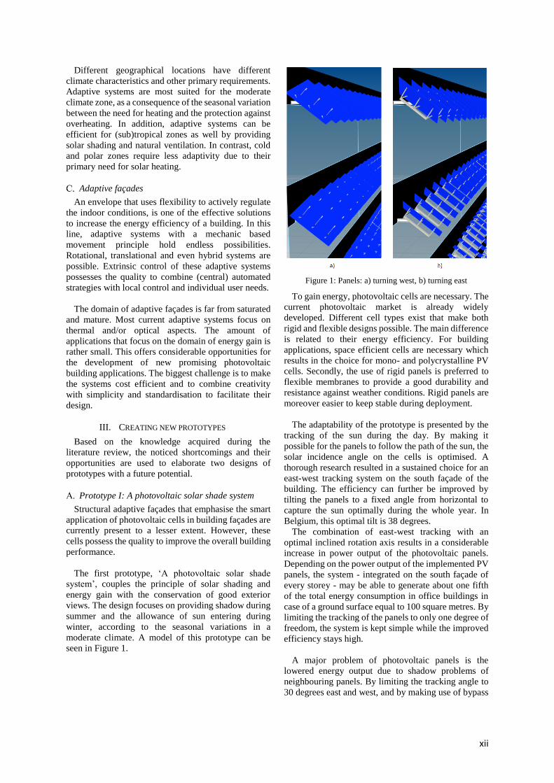
The first prototype, ‘A photovoltaic solar shade
system’, couples the principle of solar shading and
energy gain with the conservation of good exterior
views. The design focuses on providing shadow during
summer and the allowance of sun entering during
winter, according to the seasonal variations in a
moderate climate. A model of this prototype can be
seen in Figure 1.
Figure 1: Panels: a) turning west, b) turning east
To gain energy, photovoltaic cells are necessary. The
current photovoltaic market is already widely
developed. Different cell types exist that make both
rigid and flexible designs possible. The main difference
is related to their energy efficiency. For building
applications, space efficient cells are necessary which
results in the choice for mono- and polycrystalline PV
cells. Secondly, the use of rigid panels is preferred to
flexible membranes to provide a good durability and
resistance against weather conditions. Rigid panels are
moreover easier to keep stable during deployment.
The adaptability of the prototype is presented by the
tracking of the sun during the day. By making it
possible for the panels to follow the path of the sun, the
solar incidence angle on the cells is optimised. A
thorough research resulted in a sustained choice for an
east-west tracking system on the south façade of the
building. The efficiency can further be improved by
tilting the panels to a fixed angle from horizontal to
capture the sun optimally during the whole year. In
Belgium, this optimal tilt is 38 degrees.
The combination of east-west tracking with an
optimal inclined rotation axis results in a considerable
increase in power output of the photovoltaic panels.
Depending on the power output of the implemented PV
panels, the system - integrated on the south façade of
every storey - may be able to generate about one fifth
of the total energy consumption in office buildings in
case of a ground surface equal to 100 square metres. By
limiting the tracking of the panels to only one degree of
freedom, the system is kept simple while the improved
efficiency stays high.
A major problem of photovoltaic panels is the
lowered energy output due to shadow problems of
neighbouring panels. By limiting the tracking angle to
30 degrees east and west, and by making use of bypass
xiii
diodes, the energy output can be kept high and the
losses due to shadow negligible.
To make the adaptive prototype not only functional
but also aesthetically attractive, frameless panels with
glass sheets provided at both sides of the photovoltaic
cells are used. This laminated module is combined with
a lightweight aluminium carrier system at the back.
Adhesive point fixings realise the connection between
the photovoltaic module and the aluminium system.
The simultaneous movement from east to west (and
backwards) of the panels can be achieved by a push-
pull system with steel bars and a gearing wheel. This
tracking system can be foreseen close to the wall of the
building to maintain an elegant façade and to facilitate
an easy placement.
Prototype II: A perforated balcony screen
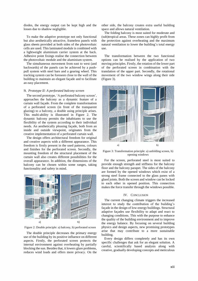
The second prototype, ‘A perforated balcony screen’,
approaches the balcony as a dynamic feature of a
curtain wall façade. From the complete transformation
of a perforated screen (in front of the transparent
glazing) to a balcony, a double using principle arises.
This multi-ability is illustrated in Figure 2. The
dynamic balcony permits the inhabitants to use the
flexibility of the system according to their individual
needs. An aesthetically pleasing façade, both from an
inside and outside viewpoint, originates from the
creative implementation of a perforated curtain wall.
The design offers architectural freedom for original
and creative aspects with a different appearance. This
freedom is firstly present in the used patterns, colours
and finishes for the perforated screen. Secondly, the
mounting freedom of the structural placement of the
curtain wall also creates different possibilities for the
overall appearance. In addition, the dimensions of the
balcony can be chosen within some ranges, taking
functionality and safety in mind.
Figure 2: Double principle: a) balcony, b) perforated screen
The double principle decreases the primary energy
use of the building by its positive influence on different
aspects. Firstly, the perforated screen protects the
internal environment against overheating by partially
blocking the sun. Besides that, it lowers glare problems,
reduces wind loads and offers more privacy. On the
other side, the balcony creates extra useful building
space and allows natural ventilation.
The folding balcony is most suited for moderate and
(sub)tropical areas. These zones can highly profit from
the protection against overheating and the maximum
natural ventilation to lower the building’s total energy
use.
The transformation between the two functional
options can be realised by the application of two
moving principles. Firstly, the rotation of the lower part
of the perforated screen in combination with the
translation of the upper part. Secondly, the rotational
movement of the two window wings along their side
(Figure 3).
Figure 3: Transformation principle: a) unfolding screen, b)
opening windows
For the screen, perforated steel is most suited to
provide enough strength and stiffness for the balcony
floor and the balcony parapet. The sides of the balcony
are formed by the opened windows which exist of a
strong steel frame connected to the glass panes with
glued joints. Both the screen and window can be locked
to each other in opened position. This connection
makes the force transfer through the windows possible.
IV. CONCLUSION
The current changing climate triggers the increased
interest to study the contribution of the building’s
façade in the design of low-energy buildings. Structural
adaptive façades use flexibility to adapt and react to
changing conditions. This with the purpose to enhance
the quality of the building environment and to improve
the energy balance. By focusing on several building
physics and design aspects, new promising prototypes
arise that may contribute to a more sustainable
building.
Every design differs completely and has its own
specific challenges that ask for an elegant solution. A
careful, scientifically based analysis along with
creative, gradually developing concepts and meticulous
xiv
calculations may contribute to an improved building
performance and internal comfort on the same time.
V. FUTURE
A lot of applications already exist, but the domain of
adaptive façades remains far from saturated. By
considering different building physics, multiple
opportunities are present to create new promising
designs.
The two developed prototypes in this paper require
application-specific and context-dependent
calculations to further optimise their design.
Furthermore, there is a lack of monitoring and
evaluating the performance of adaptive façades. New
simulation tools and whole-life evaluation methods
should be developed to judge the often challenging
adaptive designs.
ACKNOWLEDGEMENTS
The author would like to acknowledge the creative
and critical discussion with supervisor Jan Belis during
the research and completion of this paper.
xv
Contents
List of abbreviations ............................................................................................................................ xviii
List of Symbols ....................................................................................................................................... xix
1 Introduction ................................................................................................................................. 1
PART I. Literature review ......................................................................................................................... 3
2 Transformable structures ............................................................................................................ 6
2.1 Introduction ......................................................................................................................... 6
2.2 Definition ............................................................................................................................. 7
2.3 Classification ........................................................................................................................ 8
2.3.1 Rigid links – Bar elements .......................................................................................... 10
2.3.2 Rigid links – Continuous surfaces .............................................................................. 14
2.3.3 Deformable links – Bar elements .............................................................................. 17
2.3.4 Deformable links – Continuous surfaces ................................................................... 19
2.3.5 Other systems ............................................................................................................ 21
2.4 Conclusions ........................................................................................................................ 23
3 Building façades......................................................................................................................... 26
3.1 Introduction ....................................................................................................................... 26
3.2 Functional requirements ................................................................................................... 27
3.2.1 Essential requirements .............................................................................................. 27
3.2.2 Comfort increasing functions .................................................................................... 28
3.2.3 Conclusions ................................................................................................................ 32
3.3 Façade structures .............................................................................................................. 33
3.3.1 Curtain walls .............................................................................................................. 33
3.3.2 Double façades .......................................................................................................... 38
3.3.3 Conclusions ................................................................................................................ 42
3.4 Integration of building functions and structures .............................................................. 43
3.4.1 Curtain walls .............................................................................................................. 43
3.4.2 Double façades .......................................................................................................... 48
3.4.3 Overview curtain wall façade and double façade and cost comparison ................... 52
3.4.4 Orientation of the façade .......................................................................................... 54
3.4.5 Conclusions ................................................................................................................ 55
3.5 Climate zones .................................................................................................................... 56
3.5.1 Humid-warm climate / Tropical rain / Equatorial ..................................................... 57
3.5.2 Dry climate / Arid / Subtropics .................................................................................. 57
3.5.3 Warm moderate rain climate / warm temperate ..................................................... 57
3.5.4 Boreal or snow forest climate / Cold ......................................................................... 57
3.5.5 Snow climate / Polar ................................................................................................. 58
3.5.6 Sun path ..................................................................................................................... 58
3.5.7 Overview .................................................................................................................... 58
3.5.8 Conclusions case studies ........................................................................................... 60
3.6 Sustainable building .......................................................................................................... 61

xvi
4 Adaptive façades ....................................................................................................................... 64
4.1 Introduction ....................................................................................................................... 64
4.2 Definition ........................................................................................................................... 65
4.3 Adaptive façades ............................................................................................................... 68
4.3.1 General ...................................................................................................................... 68
4.3.2 Dynamic Interfaces .................................................................................................... 68
4.3.3 Ecological footprint ................................................................................................... 70
4.3.4 Structural placement ................................................................................................. 71
4.3.5 Movement ................................................................................................................. 71
4.3.6 Flexible systems: adaptability, multi-ability and evolvability .................................... 72
4.3.7 Environmental impacts during the building’s lifetime .............................................. 72
4.3.8 Control ....................................................................................................................... 73
4.3.9 Operation .................................................................................................................. 74
4.4 Classification ...................................................................................................................... 75
4.4.1 Proposal of a new classification system .................................................................... 75
4.4.2 Movement ................................................................................................................. 76
4.4.3 Control ....................................................................................................................... 80
4.4.4 Relevant physics ........................................................................................................ 80
4.4.5 Biomimetics ............................................................................................................... 82
4.5 Conclusions and future perspectives ................................................................................ 84
PART II. Design of prototypes ................................................................................................................ 85
5 Prototype I : A photovoltaic solar shade system ....................................................................... 88
5.1 Case definition ................................................................................................................... 88
5.2 PV panels ........................................................................................................................... 90
5.2.1 PV panels: general ..................................................................................................... 90
5.2.2 Flexible versus rigid cladding ..................................................................................... 93
5.2.3 Decision ..................................................................................................................... 94
5.3 Solar tracking ..................................................................................................................... 94
5.3.1 General ...................................................................................................................... 94
5.3.2 Angle of incidence ..................................................................................................... 95
5.3.3 Efficiency difference tracking systems ...................................................................... 95
5.3.4 Optimum tilt angle (single-axis trackers) - Europe .................................................... 97
5.3.5 Shadow problems ...................................................................................................... 99
5.3.6 Practical study: Belgium .......................................................................................... 101
5.4 Creation of a prototype ................................................................................................... 104
5.4.1 Dimensions .............................................................................................................. 104
5.4.2 Turning tube at a distance of the panel .................................................................. 106
5.4.3 Tracking system ....................................................................................................... 108
5.4.4 Materials, mounting system and connections ........................................................ 112
5.4.5 Forces on the panel ................................................................................................. 113
5.4.6 Force transfer .......................................................................................................... 118
5.4.7 Adhesive point fixings.............................................................................................. 121
xvii
5.4.8 Stresses and deformations ...................................................................................... 121
5.4.9 Final lay-out – Optimisation .................................................................................... 127
5.4.10 Energy calculation ................................................................................................... 129
5.5 Conclusions ...................................................................................................................... 131
6 Prototype II: A perforated balcony screen .............................................................................. 136
6.1 Case definition ................................................................................................................. 136
6.2 Prototype idea ................................................................................................................. 137
6.2.1 Double principle ...................................................................................................... 137
6.2.2 Adaptive principle ................................................................................................... 138
6.3 Creation of a prototype ................................................................................................... 141
6.3.1 Dimensions .............................................................................................................. 141
6.3.2 Materials, mounting system and connections ........................................................ 143
6.3.3 Actuating and locking system .................................................................................. 147
6.3.4 Forces on the panel ................................................................................................. 149
6.3.5 Stresses and deformations ...................................................................................... 152
6.4 Conclusions ...................................................................................................................... 157
7 General conclusion .................................................................................................................. 159
8 Future perspectives ................................................................................................................. 160
APPENDIX A. Case Studies ................................................................................................................... 161
1 Realisations.............................................................................................................................. 164
2 Prototypes ............................................................................................................................... 201
References ........................................................................................................................................... 217
List of Figures ....................................................................................................................................... 227
List of Tables ........................................................................................................................................ 232
xviii
List of abbreviations
a-Si Amorphous silicon
BIPV Building-integrated photovoltaic
CABS Climate adaptive building shells
CC2 Consequence class 2
CdTe Cadmium Telluride
CIGS Copper Indium Gallium Selenide
CO2 Carbon dioxide
DCMS Deployable closed-membrane structure
DDC Developable double corrugation
ETFE Ethylene tetrafluoroethylene
EVA Ethylene-vinyl acetate
GCR Ground cover ratio
HVAC Heating, ventilation, and air conditioning
IGU Insulated glass unit
ISA Instantaneous screw axis
LED Light-emitting diode
LTR Length-to-thickness ratio
Mono Si Monocrystalline silicon
NURBS Non-uniform rational basis spline
Poly Si Polycrystalline silicon
PTFE Polytetrafluoroethylene
PV Photovoltaic
PVB Polyvinyl butyral
PVC Polyvinyl chloride
SLE Scissor-like element
SLS Serviceability limit state
ULS Ultimate limit state
UV Ultraviolet
xix
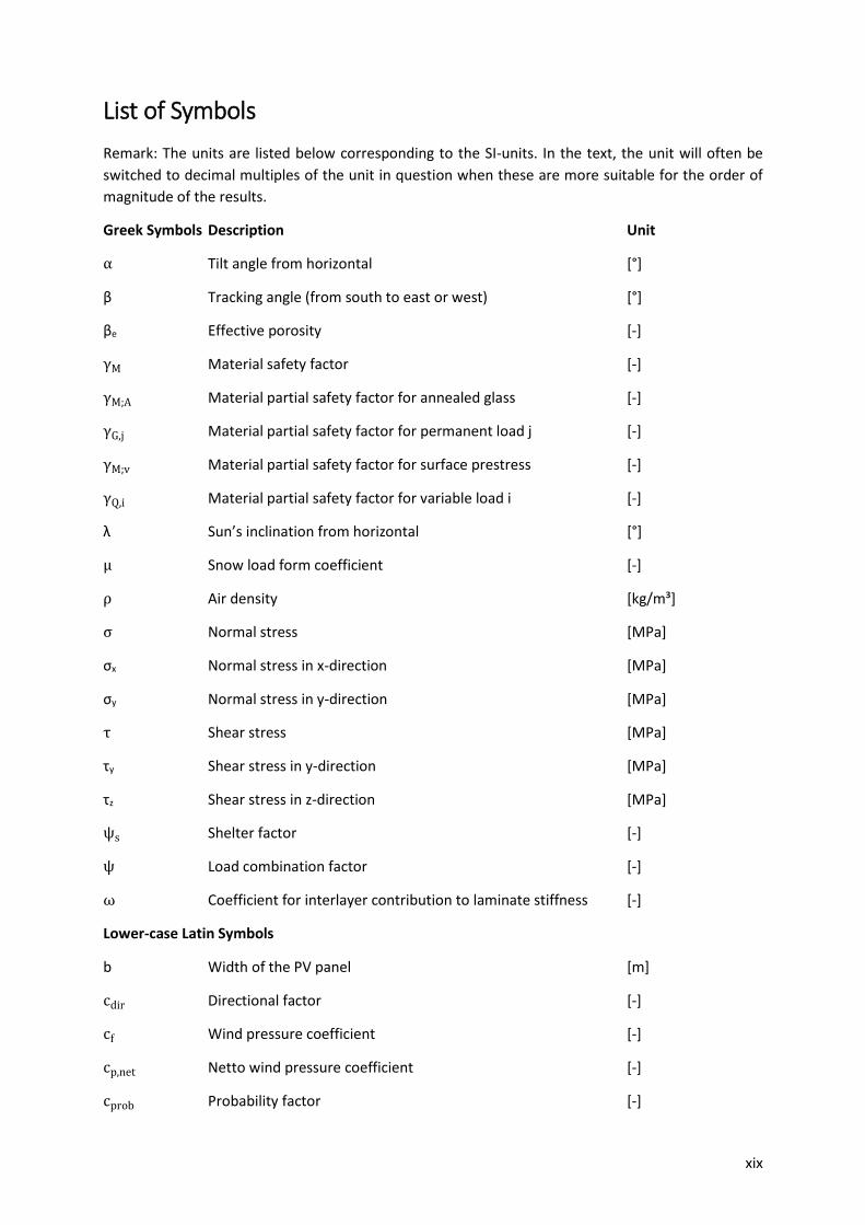
List of Symbols
Remark: The units are listed below corresponding to the SI-units. In the text, the unit will often be
switched to decimal multiples of the unit in question when these are more suitable for the order of
magnitude of the results.
Greek Symbols Description Unit
α Tilt angle from horizontal [°]
β Tracking angle (from south to east or west) [°]
βe Effective porosity [-]
γM Material safety factor [-]
γM;A Material partial safety factor for annealed glass [-]
γG,j Material partial safety factor for permanent load j [-]
γM;v Material partial safety factor for surface prestress [-]
γQ,i Material partial safety factor for variable load i [-]
λ Sun’s inclination from horizontal [°]
μ Snow load form coefficient [-]
ρ Air density [kg/m³]
σ Normal stress [MPa]
σx Normal stress in x-direction [MPa]
σy Normal stress in y-direction [MPa]
τ Shear stress [MPa]
τy Shear stress in y-direction [MPa]
τz Shear stress in z-direction [MPa]
ψs Shelter factor [-]
ψ Load combination factor [-]
ω Coefficient for interlayer contribution to laminate stiffness [-]
Lower-case Latin Symbols
b Width of the PV panel [m]
cdir Directional factor [-]
cf Wind pressure coefficient [-]
cp,net Netto wind pressure coefficient [-]
cprob Probability factor [-]
xx
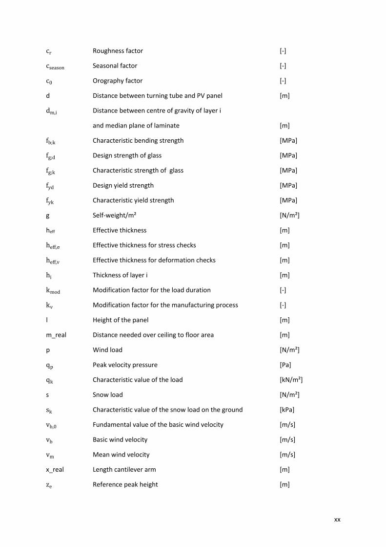
cr Roughness factor [-]
cseason Seasonal factor [-]
c0 Orography factor [-]
d Distance between turning tube and PV panel [m]
dm,i Distance between centre of gravity of layer i
and median plane of laminate [m]
fb;k Characteristic bending strength [MPa]
fg;d Design strength of glass [MPa]
fg;k Characteristic strength of glass [MPa]
fyd Design yield strength [MPa]
fyk Characteristic yield strength [MPa]
g Self-weight/m² [N/m²]
heff Effective thickness [m]
heff,σ Effective thickness for stress checks [m]
heff,v Effective thickness for deformation checks [m]
hi Thickness of layer i [m]
kmod Modification factor for the load duration [-]
kv Modification factor for the manufacturing process [-]
l Height of the panel [m]
m_real Distance needed over ceiling to floor area [m]
p Wind load [N/m²]
qp Peak velocity pressure [Pa]
qk Characteristic value of the load [kN/m²]
s Snow load [N/m²]
sk Characteristic value of the snow load on the ground [kPa]
vb,0 Fundamental value of the basic wind velocity [m/s]
vb Basic wind velocity [m/s]
vm Mean wind velocity [m/s]
x_real Length cantilever arm [m]
ze Reference peak height [m]
xxi
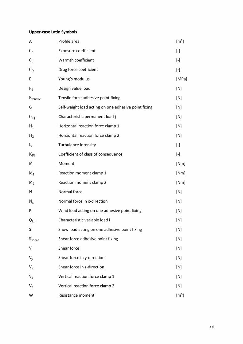
Upper-case Latin Symbols
A Profile area [m²]
Ce Exposure coefficient [-]
Ct Warmth coefficient [-]
CD Drag force coefficient [-]
E Young’s modulus [MPa]
Fd Design value load [N]
Ftensile Tensile force adhesive point fixing [N]
G Self-weight load acting on one adhesive point fixing [N]
Gk,j Characteristic permanent load j [N]
H1 Horizontal reaction force clamp 1 [N]
H2 Horizontal reaction force clamp 2 [N]
Iv Turbulence intensity [-]
KFI Coefficient of class of consequence [-]
M Moment [Nm]
M1 Reaction moment clamp 1 [Nm]
M2 Reaction moment clamp 2 [Nm]
N Normal force [N]
Nx Normal force in x-direction [N]
P Wind load acting on one adhesive point fixing [N]
Qk,i Characteristic variable load i [N]
S Snow load acting on one adhesive point fixing [N]
Sshear Shear force adhesive point fixing [N]
V Shear force [N]
Vy Shear force in y-direction [N]
Vz Shear force in z-direction [N]
V1 Vertical reaction force clamp 1 [N]
V2 Vertical reaction force clamp 2 [N]
W Resistance moment [m³]

xxii
1
1 Introduction
The prevalent climate change triggers the growing need for measures with a positive impact on the
global energy use. Buildings, both residential and commercial, are responsible for about one third of
this total energy consumption. This explains that a focus on this research area is of great importance.
The façade is the envelope of the building that forms the interface between the indoor and outdoor
climate. The total energy consumption of a building is mainly dictated by this interface. That is the
reason why concentrating on this design aspect is important for the development of a sustainable
building.
From an architectural point of view, the façade is the place where the architects can implement their
creative ideas that will determine the aesthetic appearance of the building. From the engineering point
of view, the façade is in the first place important for the influence of the design on the energy efficiency
of the building. The combination of both the architectural and the engineering input will be the
guidance for this thesis.
The conventional envelope is based on static designs that do not possess the flexibility to adapt and
react to changing conditions. However, both the building’s environment and the occupants’ wishes are
changing over time. This insight explains the growing interest towards adaptive façades. The building
envelope is no longer seen as just a shield but as a surface that can control efficiently the energy
balances. Adaptive façades add the fourth dimension of time - by implementing dynamic features -
which is an underestimated aspect that receives up till now not enough attention in the building
industry. To better understand the current state of adaptive applications, case studies are analysed.
The investigated examples can be found in Appendix A. A large part of these examples are still quite
complex and more research and experience is necessary to facilitate and improve future economic
designs.
To create adaptive façades, transformable structures are needed. These structures are characterised
by controlled movement during transformation, but result in static structures once the mechanism is
locked in place. A good understanding of this type of structures is necessary to be able to develop
smart and creative adaptive façades.
From this viewpoint, the following important research questions can be formulated for the literature
study:
What is the state of the art of transformable structures/building façades/adaptive façades?
How can an adaptive façade be made with a transformable structure?
Which type of transformable structure is best suited for an adaptive façade?
Which type of façade is best suited for an adaptive façade?
The domain of designing adaptive façades possesses a wider range of solutions than only structural
adaptability. The literature research will shortly mention the other possibilities but will focus on the
structural domain in the issue of adaptive façades. In this line, the accomplishment of the literature
study about transformable structures, building façades and adaptive façades will be followed by a
second part that will focus on the design of some structural adaptive prototypes. These prototypes
investigate current shortcomings in existing applications with the purpose of a more sustainable
building in mind.

2

3
PART I. Literature review

4
5
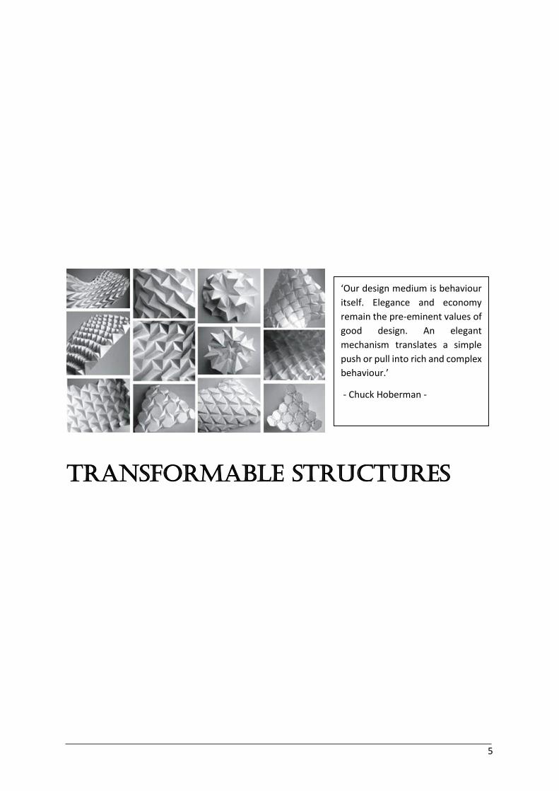
Transformable Structures
‘Our design medium is behaviour
itself. Elegance and economy
remain the pre-eminent values of
good design. An elegant
mechanism translates a simple
push or pull into rich and complex
behaviour.’
- Chuck Hoberman -
2.1 Introduction 6
2 Transformable structures 2.1 Introduction
Transformable and deployable architecture possesses unique opportunities. This kind of architecture
aims for structures that are efficient, economic and elegant. The elegance of the structure is related
to the transformation of the structure and its resulting behaviour. Changing behaviour due to
transformations creates possibilities to design structures that are more aesthetically pleasing because
of their exciting dynamics. The changing behaviour is often regulated by dynamic feedback from the
environment or other types of smart technology. Control systems based on feedback are intelligent
ways to change the physical properties of structures in an effective manner.
The dynamic behaviour makes it possible to improve the sustainability of structures. Transformable
design is multidisciplinary. It contributes to create not only structures but also products and
environments that change their size and shape. This adaptive, interactive approach is needed to deal
with the current climate change. Transformable architecture may contribute in a creative way in the
design of buildings to save energy and enhance the quality of the building environment.
The integration of adaptive elements in the design process requires mathematics, mechanics and
structural engineering. Chuck Hoberman states that a process of transformation needs to respect three
requirements to come to fluid responsiveness, adaptability and ease of use. These three aspects are a
complete and fully three-dimensional transformation that is smooth and continuous and on the same
time reversible and repeatable.
2.2 Definition 7
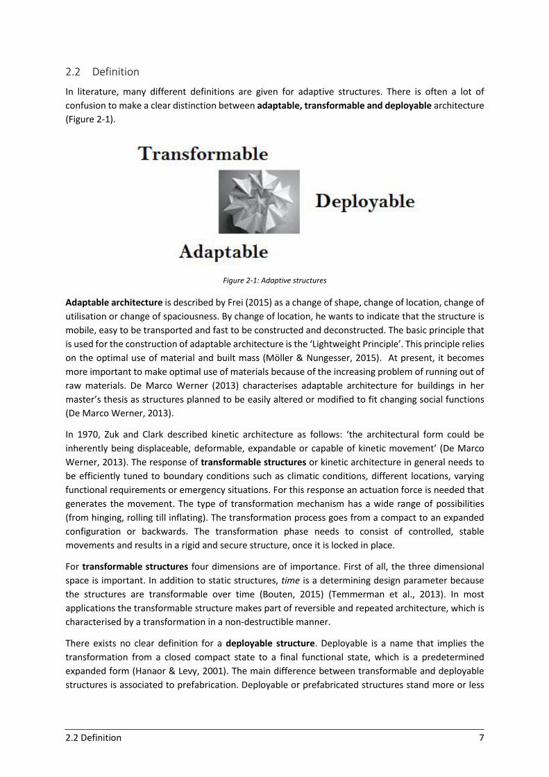
2.2 Definition
In literature, many different definitions are given for adaptive structures. There is often a lot of
confusion to make a clear distinction between adaptable, transformable and deployable architecture
(Figure 2-1).
Figure 2-1: Adaptive structures
Adaptable architecture is described by Frei (2015) as a change of shape, change of location, change of
utilisation or change of spaciousness. By change of location, he wants to indicate that the structure is
mobile, easy to be transported and fast to be constructed and deconstructed. The basic principle that
is used for the construction of adaptable architecture is the ‘Lightweight Principle’. This principle relies
on the optimal use of material and built mass (Möller & Nungesser, 2015). At present, it becomes
more important to make optimal use of materials because of the increasing problem of running out of
raw materials. De Marco Werner (2013) characterises adaptable architecture for buildings in her
master’s thesis as structures planned to be easily altered or modified to fit changing social functions
(De Marco Werner, 2013).
In 1970, Zuk and Clark described kinetic architecture as follows: ‘the architectural form could be
inherently being displaceable, deformable, expandable or capable of kinetic movement’ (De Marco
Werner, 2013). The response of transformable structures or kinetic architecture in general needs to
be efficiently tuned to boundary conditions such as climatic conditions, different locations, varying
functional requirements or emergency situations. For this response an actuation force is needed that
generates the movement. The type of transformation mechanism has a wide range of possibilities
(from hinging, rolling till inflating). The transformation process goes from a compact to an expanded
configuration or backwards. The transformation phase needs to consist of controlled, stable
movements and results in a rigid and secure structure, once it is locked in place.
For transformable structures four dimensions are of importance. First of all, the three dimensional
space is important. In addition to static structures, time is a determining design parameter because
the structures are transformable over time (Bouten, 2015) (Temmerman et al., 2013). In most
applications the transformable structure makes part of reversible and repeated architecture, which is
characterised by a transformation in a non-destructible manner.
There exists no clear definition for a deployable structure. Deployable is a name that implies the
transformation from a closed compact state to a final functional state, which is a predetermined
expanded form (Hanaor & Levy, 2001). The main difference between transformable and deployable
structures is associated to prefabrication. Deployable or prefabricated structures stand more or less

2.3 Classification 8
for the pre-assembly of the entire structure in a factory and the deploying of the structure on site (De
Marco Werner, 2013).
Although the differences between adaptable, transformable and deployable structures are not always
clear, there is no doubt about their useful applications. Adaptive structures can be efficiently used for
purposes as temporary spaces, climatic response in buildings and buildings with change of use.
2.3 Classification
To create a clear overview and to gain insight, making a classification in transformable architecture is
necessary. In literature, a lot of classifications have been made. The choice of the classification system
depends on which parameters are of predominant importance for the specific study. A very useful one,
is the classification by Hanaor and Levy (2001) (Figure 2-2).
Figure 2-2: Hanaor classification system (Hanaor & Levy, 2001)
2.3 Classification 9
This classification is based on two main parameters: kinematics and morphology (structural-
morphological properties). For transformable structures, morphological aspects are most important.
They describe the way of deployment of the structure. In the master’s thesis of Bouten (2015), a third
parameter, mobility, is added to this classification. Mobility represents the degrees of freedom of the
structure in case it is constructed of rigid link mechanisms. Considering the first parameter, the
kinematic degrees of freedom that characterise a mechanism, two types of release are possible. A
hinge, which results in a rotational degree of freedom, and a slide, resulting in a translational degree
of freedom. The secondary parameter, morphological aspects, makes a difference in the elements that
form the transformable parts of the structure. Each of the parameters is further subdivided into
substructures. The kinematic subdivision is between rigid links and deformable components. The
morphologic subdivision makes a distinction between lattice (bar structures) and stressed-skin
structures, which are continuous surfaces. In lattice structures, the load-bearing structures are
discrete members (bar elements), while in the continuous surfaces, the surface covering itself carries
out the load-bearing function. A third possible class is the combination of both, resulting in hybrid
structures.
Structures often need auxiliary permanent or non-permanent supports for their stability. If structures
are stable without the use of a support, they are called dynamic, self-erecting structures. These
structures are most interesting to apply in adaptive façades. Mostly, structures that have more degrees
of freedom are more flexible and need to be stabilised to be able to carry loads. Curved surfaces are
more resistant than planar structures. They can be subdivided in three important groups, the single
curvature structures, double curvature structures and freeform structures. The single curvature
structures are characterised by a zero Gaussian curve. Double curvature structures can be synclastic
(positive Gaussian curve) or anticlastic (negative Gaussian curve). Freeform curved structures have
much more flexibility compared to the previous two types. Typical known freeform curves are Bézier
curves, B-spline curves or NURBS (Non-uniform rational basis spline) curves. The first ones are
structural most easy and therefore most applied. The NURBS curves are the most complex of the three
given examples (Susam, 2013).
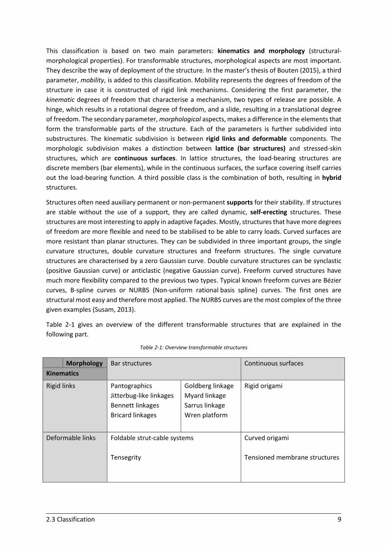
Table 2-1 gives an overview of the different transformable structures that are explained in the
following part.
Table 2-1: Overview transformable structures
Morphology Bar structures Continuous surfaces
Kinematics
Rigid links Pantographics
Jitterbug-like linkages
Bennett linkages
Bricard linkages
Goldberg linkage
Myard linkage
Sarrus linkage
Wren platform
Rigid origami
Deformable links Foldable strut-cable systems
Tensegrity
Curved origami
Tensioned membrane structures
2.3 Classification 10
2.3.1 Rigid links – Bar elements
2.3.1.1 SLE’s (Scissor-Like Elements) - Pantographic structures
Lattice bar structures (also called SLE’s) are divided into three major types in the chart of Hanaor: the
double-layer grids, single-layer grids and linear grids (masts or spines). Most scissor-like elements are
foreseen of a cover layer. The grid, composed of bar elements, forms the primary load-bearing
structure; contrarily to the covering, which forms the non-load-bearing surface. The interaction
between the grid and the covering, both in deployed and undeployed state, is crucial. Scissor elements
are often combined with flexible cladding components such as membranes as covering.
Scissor units, also called pantographs, are pivot-hinge structures. These mobile, deployable structures
consist of hinged bars (Temmerman et al., 2013). A basic scissor unit is composed of two bars,
interconnected by a revolute joint at the intermediate hinge point. This allows a free rotation of the
bars around the axis perpendicular to the plane of the pantograph. Planar and spatial grids can be
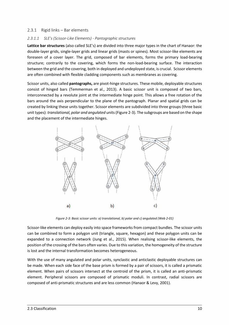
created by linking these units together. Scissor elements are subdivided into three groups (three basic
unit types): translational, polar and angulated units (Figure 2-3). The subgroups are based on the shape
and the placement of the intermediate hinges.
Figure 2-3: Basic scissor units: a) translational, b) polar and c) angulated (Web 2-01)
Scissor-like elements can deploy easily into space frameworks from compact bundles. The scissor units
can be combined to form a polygon unit (triangle, square, hexagon) and these polygon units can be
expanded to a connection network (Jung et al., 2015). When realising scissor-like elements, the
position of the crossing of the bars often varies. Due to this variation, the homogeneity of the structure
is lost and the internal transformation becomes heterogeneous.
With the use of many angulated and polar units, synclastic and anticlastic deployable structures can
be made. When each side face of the base prism is formed by a pair of scissors, it is called a prismatic
element. When pairs of scissors intersect at the centroid of the prism, it is called an anti-prismatic
element. Peripheral scissors are composed of prismatic moduli. In contrast, radial scissors are
composed of anti-prismatic structures and are less common (Hanaor & Levy, 2001).
2.3 Classification 11
The grid of scissor structures has in architecture the popular trend to form the network of the principal
curvature lines. This creates a more efficient way of translating the forces that act on the structure
(Bouten, 2015). Pantographs are in architecture often used in combination with a movable supporting
structure, like struts, arches or frames. These are substructures which are permanent and can act as
supporting system for the transformable structure (Susam, 2013).
For a successful deployment and folding, issues like the shape of elements, the type of material, the
deployment behaviour, joint connections should be carefully considered. For the total performance,
not only the structural performance in deployed and undeployed state is important but also the
dynamic performance during transformation plays a major role (Umweni & Ianakiev, 2015).
2.3.1.2 Jitterbug-like linkages
Mechanisms that possess only one degree of freedom are called Jitterbug-like linkages. These
mechanisms can transform from one polyhedron into a different one by using only one single process.
Fuller was the first person who invented and created a Jitterbug mechanism. The polyhedron structure
that he used was an octahedron. The Jitterbug transformation is not only applicable for an octahedron
but can be applied to the different polyhedron groups. Most often, polyhedrons from the Platonic and
Archimedean solids are used (Bouten, 2015).
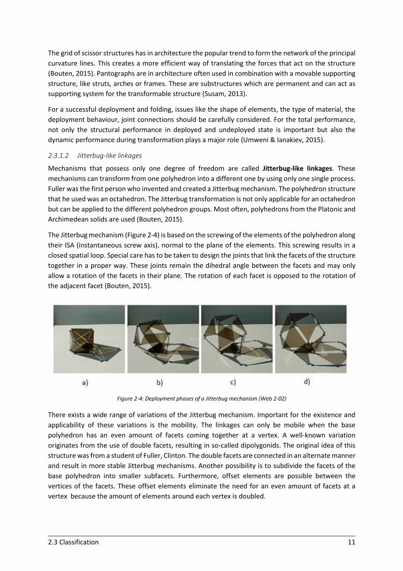
The Jitterbug mechanism (Figure 2-4) is based on the screwing of the elements of the polyhedron along
their ISA (instantaneous screw axis), normal to the plane of the elements. This screwing results in a
closed spatial loop. Special care has to be taken to design the joints that link the facets of the structure
together in a proper way. These joints remain the dihedral angle between the facets and may only
allow a rotation of the facets in their plane. The rotation of each facet is opposed to the rotation of
the adjacent facet (Bouten, 2015).
Figure 2-4: Deployment phases of a Jitterbug mechanism (Web 2-02)
There exists a wide range of variations of the Jitterbug mechanism. Important for the existence and
applicability of these variations is the mobility. The linkages can only be mobile when the base
polyhedron has an even amount of facets coming together at a vertex. A well-known variation
originates from the use of double facets, resulting in so-called dipolygonids. The original idea of this
structure was from a student of Fuller, Clinton. The double facets are connected in an alternate manner
and result in more stable Jitterbug mechanisms. Another possibility is to subdivide the facets of the
base polyhedron into smaller subfacets. Furthermore, offset elements are possible between the
vertices of the facets. These offset elements eliminate the need for an even amount of facets at a
vertex because the amount of elements around each vertex is doubled.
2.3 Classification 12
2.3.1.3 Linkages and platforms
Next to SLE’s and Jitterbug mechanisms, overconstrained linkages are another application of rigid bar
elements. These linkages all possess one degree of freedom and are connected by only revolute joints.
The term overconstrained is related to the prediction of less degrees of freedom according to the
Grübler criterion. Different types of these linkages are treated below.
Bennett linkage
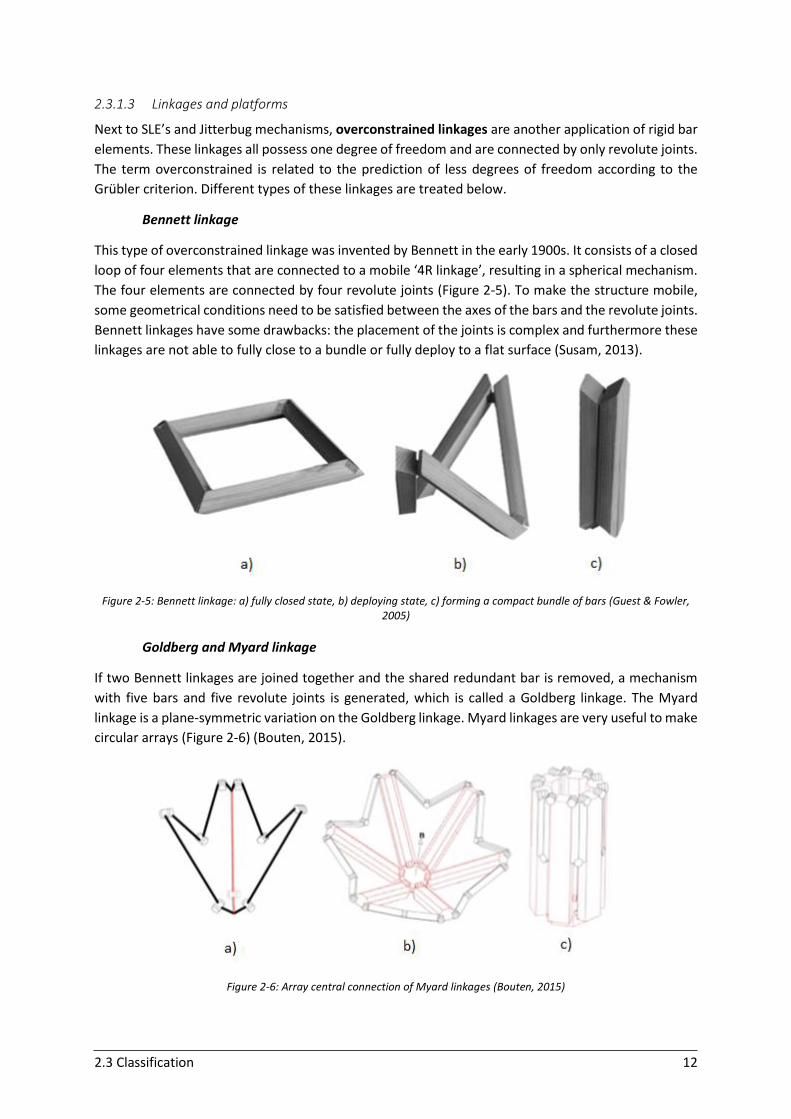
This type of overconstrained linkage was invented by Bennett in the early 1900s. It consists of a closed
loop of four elements that are connected to a mobile ‘4R linkage’, resulting in a spherical mechanism.
The four elements are connected by four revolute joints (Figure 2-5). To make the structure mobile,
some geometrical conditions need to be satisfied between the axes of the bars and the revolute joints.
Bennett linkages have some drawbacks: the placement of the joints is complex and furthermore these
linkages are not able to fully close to a bundle or fully deploy to a flat surface (Susam, 2013).
Figure 2-5: Bennett linkage: a) fully closed state, b) deploying state, c) forming a compact bundle of bars (Guest & Fowler, 2005)
Goldberg and Myard linkage
If two Bennett linkages are joined together and the shared redundant bar is removed, a mechanism
with five bars and five revolute joints is generated, which is called a Goldberg linkage. The Myard
linkage is a plane-symmetric variation on the Goldberg linkage. Myard linkages are very useful to make
circular arrays (Figure 2-6) (Bouten, 2015).
Figure 2-6: Array central connection of Myard linkages (Bouten, 2015)
2.3 Classification 13
Bricard linkage
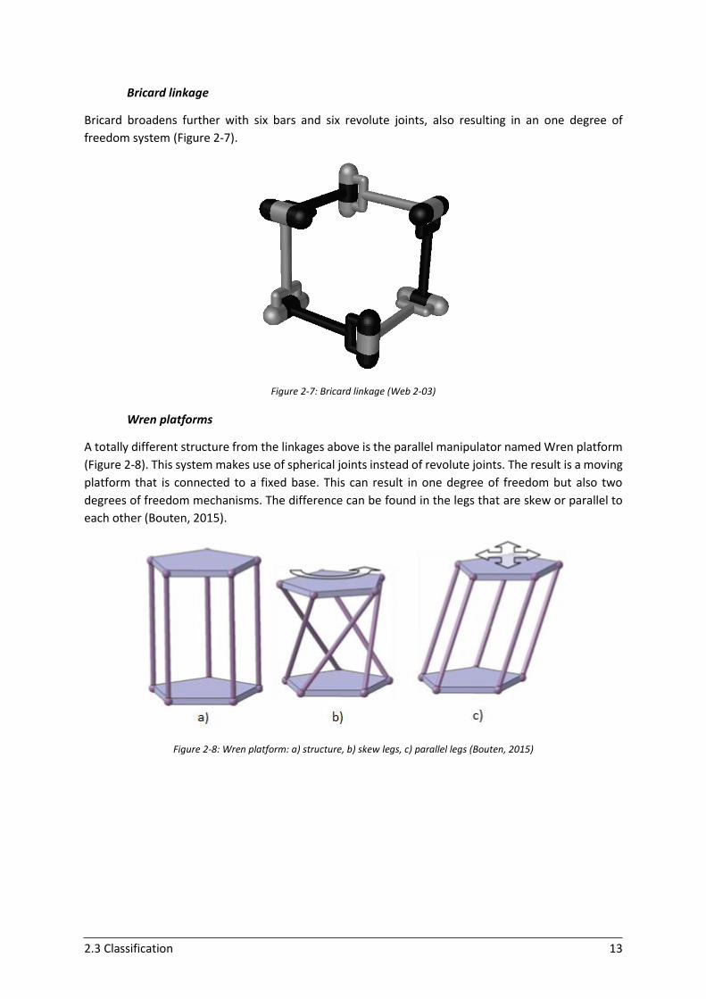
Bricard broadens further with six bars and six revolute joints, also resulting in an one degree of
freedom system (Figure 2-7).
Figure 2-7: Bricard linkage (Web 2-03)
Wren platforms
A totally different structure from the linkages above is the parallel manipulator named Wren platform
(Figure 2-8). This system makes use of spherical joints instead of revolute joints. The result is a moving
platform that is connected to a fixed base. This can result in one degree of freedom but also two
degrees of freedom mechanisms. The difference can be found in the legs that are skew or parallel to
each other (Bouten, 2015).
Figure 2-8: Wren platform: a) structure, b) skew legs, c) parallel legs (Bouten, 2015)
2.3 Classification 14
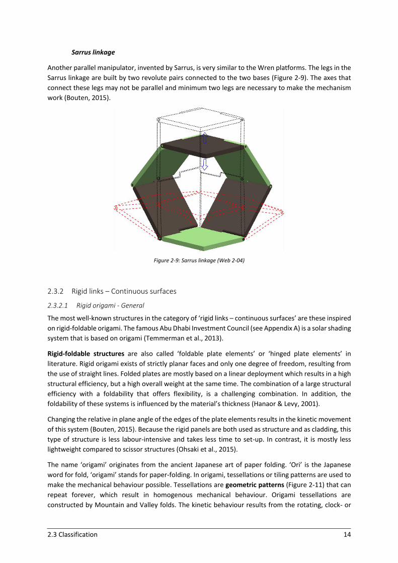
Sarrus linkage
Another parallel manipulator, invented by Sarrus, is very similar to the Wren platforms. The legs in the
Sarrus linkage are built by two revolute pairs connected to the two bases (Figure 2-9). The axes that
connect these legs may not be parallel and minimum two legs are necessary to make the mechanism
work (Bouten, 2015).
Figure 2-9: Sarrus linkage (Web 2-04)
2.3.2 Rigid links – Continuous surfaces
2.3.2.1 Rigid origami - General
The most well-known structures in the category of ‘rigid links – continuous surfaces’ are these inspired
on rigid-foldable origami. The famous Abu Dhabi Investment Council (see Appendix A) is a solar shading
system that is based on origami (Temmerman et al., 2013).
Rigid-foldable structures are also called ‘foldable plate elements’ or ‘hinged plate elements’ in
literature. Rigid origami exists of strictly planar faces and only one degree of freedom, resulting from
the use of straight lines. Folded plates are mostly based on a linear deployment which results in a high
structural efficiency, but a high overall weight at the same time. The combination of a large structural
efficiency with a foldability that offers flexibility, is a challenging combination. In addition, the
foldability of these systems is influenced by the material’s thickness (Hanaor & Levy, 2001).
Changing the relative in plane angle of the edges of the plate elements results in the kinetic movement
of this system (Bouten, 2015). Because the rigid panels are both used as structure and as cladding, this
type of structure is less labour-intensive and takes less time to set-up. In contrast, it is mostly less
lightweight compared to scissor structures (Ohsaki et al., 2015).
The name ‘origami’ originates from the ancient Japanese art of paper folding. ‘Ori’ is the Japanese
word for fold, ‘origami’ stands for paper-folding. In origami, tessellations or tiling patterns are used to
make the mechanical behaviour possible. Tessellations are geometric patterns (Figure 2-11) that can
repeat forever, which result in homogenous mechanical behaviour. Origami tessellations are
constructed by Mountain and Valley folds. The kinetic behaviour results from the rotating, clock- or
2.3 Classification 15
counterclockwise, of the plate elements around these folds (Bouten, 2015). Folding patterns can be
optimised by placing the pattern along the principal moment lines in order to reduce forces and avoid
peak stresses (Trautz & Cierniak, 2011).
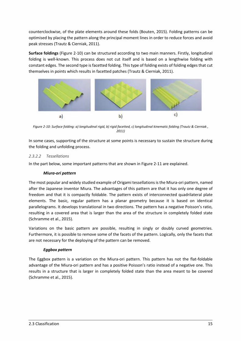
Surface foldings (Figure 2-10) can be structured according to two main manners. Firstly, longitudinal
folding is well-known. This process does not cut itself and is based on a lengthwise folding with
constant edges. The second type is facetted folding. This type of folding exists of folding edges that cut
themselves in points which results in facetted patches (Trautz & Cierniak, 2011).
Figure 2-10: Surface folding: a) longitudinal rigid, b) rigid facetted, c) longitudinal kinematic folding (Trautz & Cierniak , 2011)
In some cases, supporting of the structure at some points is necessary to sustain the structure during
the folding and unfolding process.
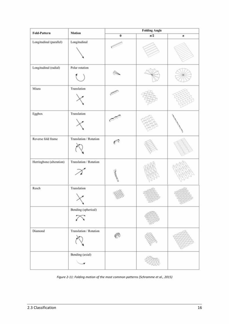
2.3.2.2 Tessellations
In the part below, some important patterns that are shown in Figure 2-11 are explained.
Miura-ori pattern
The most popular and widely studied example of Origami tessellations is the Miura-ori pattern, named
after the Japanese inventor Miura. The advantages of this pattern are that it has only one degree of
freedom and that it is compactly foldable. The pattern exists of interconnected quadrilateral plate
elements. The basic, regular pattern has a planar geometry because it is based on identical
parallelograms. It develops translational in two directions. The pattern has a negative Poisson’s ratio,
resulting in a covered area that is larger than the area of the structure in completely folded state
(Schramme et al., 2015).
Variations on the basic pattern are possible, resulting in singly or doubly curved geometries.
Furthermore, it is possible to remove some of the facets of the pattern. Logically, only the facets that
are not necessary for the deploying of the pattern can be removed.
Eggbox pattern
The Eggbox pattern is a variation on the Miura-ori pattern. This pattern has not the flat-foldable
advantage of the Miura-ori pattern and has a positive Poisson’s ratio instead of a negative one. This
results in a structure that is larger in completely folded state than the area meant to be covered
(Schramme et al., 2015).
2.3 Classification 16
Figure 2-11: Folding motion of the most common patterns (Schramme et al., 2015)
2.3 Classification 17
Yoshimura pattern (Diamond pattern)
In contrast to the Miura-ori pattern, the Yoshimura pattern is based on triangular elements instead of
parallelograms connected by hinges. Furthermore, one angle must be at least 90 degrees and all
elements must have the same shape and equal apex angles. The most often seen surface with this
pattern is singly curved; nevertheless doubly curved surfaces are possible as well. The Yoshimura
pattern has, as the Miura-ori pattern, the advantage to be completely foldable. However, it is more
complicated because it is characterised by more degrees of freedom. By increasing the number of
folds, the load-bearing capacity of the structure increases. By increasing the apex angel, the clear width
increases, but also the number of elements and the hinges (Ohsaki et al., 2015).
Resch pattern
The Resch pattern is named after the geometrist Resch. This regular pattern exists of triangular facets
and typically has two degrees of freedom. It is characterised by two facet layers. The front layer exists
of triangular facets that rotate around their normal axes through their centroid. The back layer is
‘tucked in’ between the front layers. The pattern not always exists of only triangular facets, but also
square and hexagonal facets are often used (Bouten, 2015).
2.3.2.3 Remarks
The maximum compactness of continuous surfaces is in general much lower compared to a structure
that consists of bar elements. In contrast, the distribution of forces can be very efficient, because the
loads can be more spread instead of being locally concentrated.
Rigid-foldable origami is rather unexplored. A lot of problems, like hinges, plate thickness,
waterproofing and compactness need further research. In general, the folding process of deployable
surfaces is interesting for the active control of light; more research can be very promising.
Furthermore, the influence of loads on the folded system and the different deployment states need to
be examined. Also the material properties need further investigation. The demand for natural light is
in conflict with the density of most plates. Synthetic materials can be a promising solution for this
problem (Schramme et al., 2015).
A special application of scissor systems and panel systems is the deployment of linked panel units using
shape recovery of bent super-elastic alloys. In this principle, the shape-memory and shape-recovery
of super-elastic alloys act as a lightweight actuator for the deployment. The panel unit can be folded
and deployed like a scissors mechanism. This system is very useful for applications in combination with
solar panels (Takatsuka, 2015).
2.3.3 Deformable links – Bar elements
Strut-cable systems combine rigid bars with cables. The big advantage of this principle is that it can
optimise the conflicting requirements of deploying, simplicity and structural efficiency (Hanaor & Levy,
2001). The most important and dominating concepts are the tensegrity structures. Strut-cable
structures are very promising for large span applications because they have a higher structural
efficiency than SLE’s. SLE’s have a low structural efficiency in terms of load-bearing capacity relative to
self-weight. The structural efficiency of strut-cable systems is also better than conventional double-
layer space trusses.
2.3 Classification 18
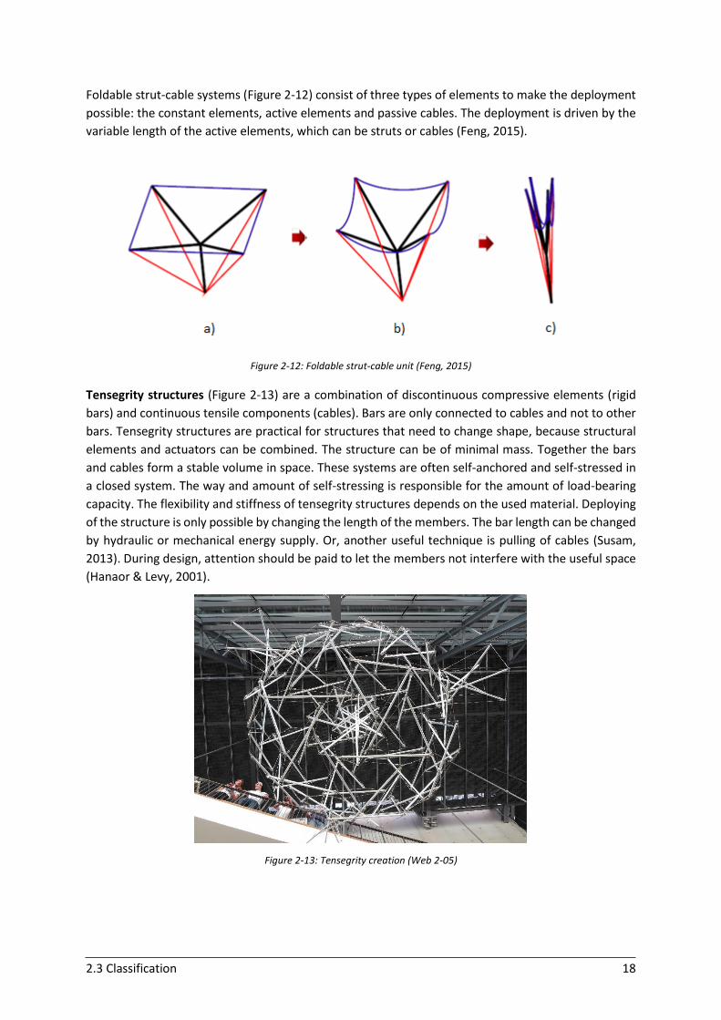
Foldable strut-cable systems (Figure 2-12) consist of three types of elements to make the deployment
possible: the constant elements, active elements and passive cables. The deployment is driven by the
variable length of the active elements, which can be struts or cables (Feng, 2015).
Figure 2-12: Foldable strut-cable unit (Feng, 2015)
Tensegrity structures (Figure 2-13) are a combination of discontinuous compressive elements (rigid
bars) and continuous tensile components (cables). Bars are only connected to cables and not to other
bars. Tensegrity structures are practical for structures that need to change shape, because structural
elements and actuators can be combined. The structure can be of minimal mass. Together the bars
and cables form a stable volume in space. These systems are often self-anchored and self-stressed in
a closed system. The way and amount of self-stressing is responsible for the amount of load-bearing
capacity. The flexibility and stiffness of tensegrity structures depends on the used material. Deploying
of the structure is only possible by changing the length of the members. The bar length can be changed
by hydraulic or mechanical energy supply. Or, another useful technique is pulling of cables (Susam,
2013). During design, attention should be paid to let the members not interfere with the useful space
(Hanaor & Levy, 2001).
Figure 2-13: Tensegrity creation (Web 2-05)
2.3 Classification 19
2.3.4 Deformable links – Continuous surfaces
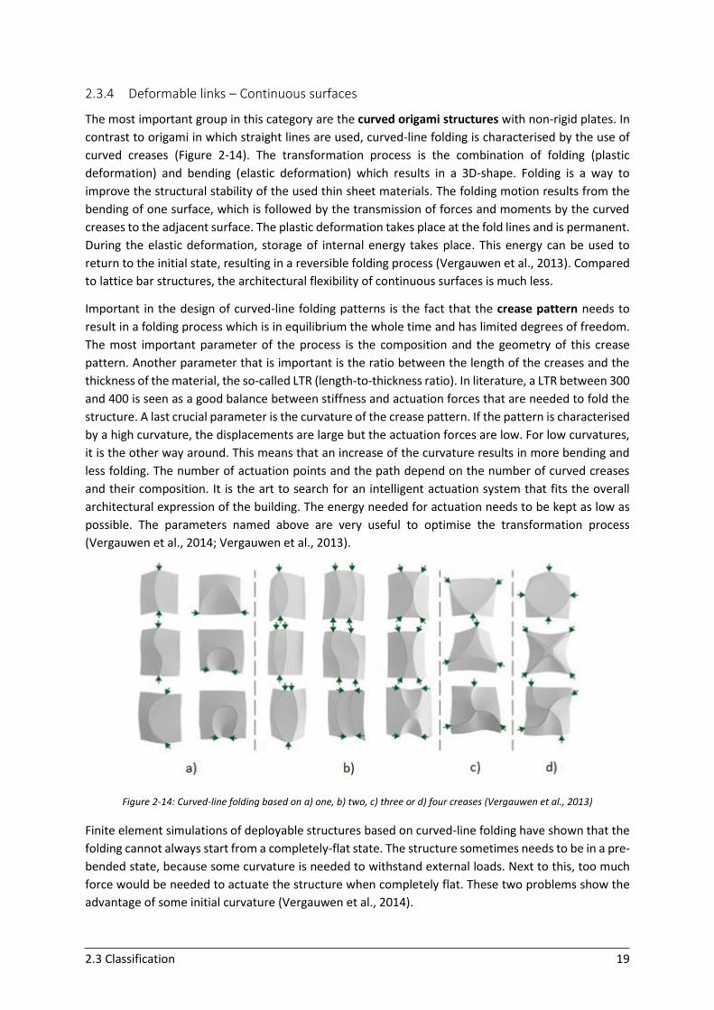
The most important group in this category are the curved origami structures with non-rigid plates. In
contrast to origami in which straight lines are used, curved-line folding is characterised by the use of
curved creases (Figure 2-14). The transformation process is the combination of folding (plastic
deformation) and bending (elastic deformation) which results in a 3D-shape. Folding is a way to
improve the structural stability of the used thin sheet materials. The folding motion results from the
bending of one surface, which is followed by the transmission of forces and moments by the curved
creases to the adjacent surface. The plastic deformation takes place at the fold lines and is permanent.
During the elastic deformation, storage of internal energy takes place. This energy can be used to
return to the initial state, resulting in a reversible folding process (Vergauwen et al., 2013). Compared
to lattice bar structures, the architectural flexibility of continuous surfaces is much less.
Important in the design of curved-line folding patterns is the fact that the crease pattern needs to
result in a folding process which is in equilibrium the whole time and has limited degrees of freedom.
The most important parameter of the process is the composition and the geometry of this crease
pattern. Another parameter that is important is the ratio between the length of the creases and the
thickness of the material, the so-called LTR (length-to-thickness ratio). In literature, a LTR between 300
and 400 is seen as a good balance between stiffness and actuation forces that are needed to fold the
structure. A last crucial parameter is the curvature of the crease pattern. If the pattern is characterised
by a high curvature, the displacements are large but the actuation forces are low. For low curvatures,
it is the other way around. This means that an increase of the curvature results in more bending and
less folding. The number of actuation points and the path depend on the number of curved creases
and their composition. It is the art to search for an intelligent actuation system that fits the overall
architectural expression of the building. The energy needed for actuation needs to be kept as low as
possible. The parameters named above are very useful to optimise the transformation process
(Vergauwen et al., 2014; Vergauwen et al., 2013).
Figure 2-14: Curved-line folding based on a) one, b) two, c) three or d) four creases (Vergauwen et al., 2013)
Finite element simulations of deployable structures based on curved-line folding have shown that the
folding cannot always start from a completely-flat state. The structure sometimes needs to be in a pre-
bended state, because some curvature is needed to withstand external loads. Next to this, too much
force would be needed to actuate the structure when completely flat. These two problems show the
advantage of some initial curvature (Vergauwen et al., 2014).
2.3 Classification 20
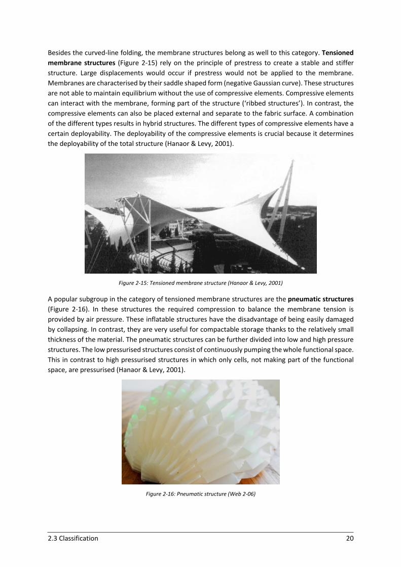
Besides the curved-line folding, the membrane structures belong as well to this category. Tensioned
membrane structures (Figure 2-15) rely on the principle of prestress to create a stable and stiffer
structure. Large displacements would occur if prestress would not be applied to the membrane.
Membranes are characterised by their saddle shaped form (negative Gaussian curve). These structures
are not able to maintain equilibrium without the use of compressive elements. Compressive elements
can interact with the membrane, forming part of the structure (‘ribbed structures’). In contrast, the
compressive elements can also be placed external and separate to the fabric surface. A combination
of the different types results in hybrid structures. The different types of compressive elements have a
certain deployability. The deployability of the compressive elements is crucial because it determines
the deployability of the total structure (Hanaor & Levy, 2001).
Figure 2-15: Tensioned membrane structure (Hanaor & Levy, 2001)
A popular subgroup in the category of tensioned membrane structures are the pneumatic structures
(Figure 2-16). In these structures the required compression to balance the membrane tension is
provided by air pressure. These inflatable structures have the disadvantage of being easily damaged
by collapsing. In contrast, they are very useful for compactable storage thanks to the relatively small
thickness of the material. The pneumatic structures can be further divided into low and high pressure
structures. The low pressurised structures consist of continuously pumping the whole functional space.
This in contrast to high pressurised structures in which only cells, not making part of the functional
space, are pressurised (Hanaor & Levy, 2001).
Figure 2-16: Pneumatic structure (Web 2-06)
2.3 Classification 21
2.3.5 Other systems
The different types in the classification of Hanaor and Levy (Figure 2-2) can be combined to form hybrid
structures. The integration of mixed strut-cable systems with a covering is an example of a useful
combination. This can result in very smart and promising structures but still needs further research.
Some examples of promising hybrid solutions are explained below.
2.3.5.1 Ori-ssors
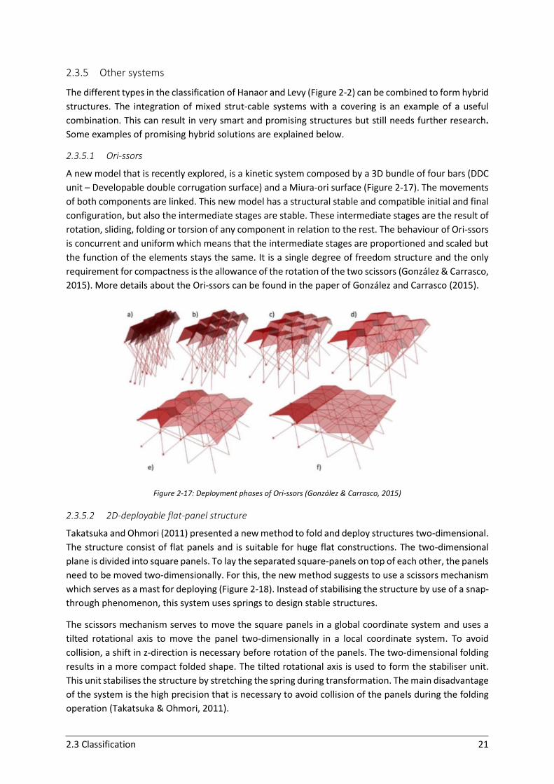
A new model that is recently explored, is a kinetic system composed by a 3D bundle of four bars (DDC
unit – Developable double corrugation surface) and a Miura-ori surface (Figure 2-17). The movements
of both components are linked. This new model has a structural stable and compatible initial and final
configuration, but also the intermediate stages are stable. These intermediate stages are the result of
rotation, sliding, folding or torsion of any component in relation to the rest. The behaviour of Ori-ssors
is concurrent and uniform which means that the intermediate stages are proportioned and scaled but
the function of the elements stays the same. It is a single degree of freedom structure and the only
requirement for compactness is the allowance of the rotation of the two scissors (González & Carrasco,
2015). More details about the Ori-ssors can be found in the paper of González and Carrasco (2015).
Figure 2-17: Deployment phases of Ori-ssors (González & Carrasco, 2015)
2.3.5.2 2D-deployable flat-panel structure
Takatsuka and Ohmori (2011) presented a new method to fold and deploy structures two-dimensional.
The structure consist of flat panels and is suitable for huge flat constructions. The two-dimensional
plane is divided into square panels. To lay the separated square-panels on top of each other, the panels
need to be moved two-dimensionally. For this, the new method suggests to use a scissors mechanism
which serves as a mast for deploying (Figure 2-18). Instead of stabilising the structure by use of a snap-
through phenomenon, this system uses springs to design stable structures.
The scissors mechanism serves to move the square panels in a global coordinate system and uses a
tilted rotational axis to move the panel two-dimensionally in a local coordinate system. To avoid
collision, a shift in z-direction is necessary before rotation of the panels. The two-dimensional folding
results in a more compact folded shape. The tilted rotational axis is used to form the stabiliser unit.
This unit stabilises the structure by stretching the spring during transformation. The main disadvantage
of the system is the high precision that is necessary to avoid collision of the panels during the folding
operation (Takatsuka & Ohmori, 2011).
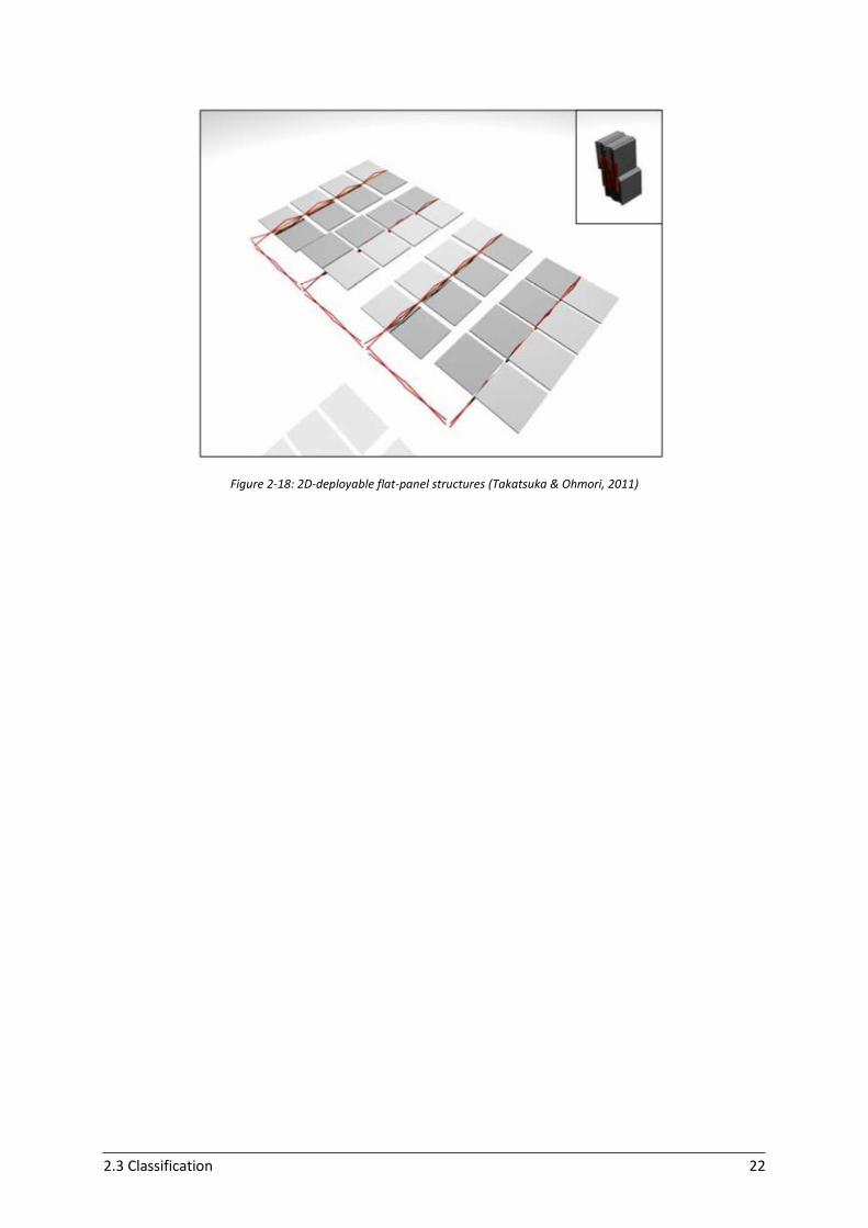
2.3 Classification 22
Figure 2-18: 2D-deployable flat-panel structures (Takatsuka & Ohmori, 2011)
2.4 Conclusions 23
2.4 Conclusions
The design of transformable structures is focused on the enabling of the structure to adapt to changing
circumstances. This capacity implies a physical transformation triggered by a sudden need
(emergency), changing climate (rain, wind, heat/cold, sun), changing functional requirements or other
changing boundary conditions. This chapter focused on transformation in terms of deployment.
Transformable systems require mostly lightweight structures combined with an optimal structural
performance. Besides the type of transformation, the materials that are used are of great importance
and have an influence on the performance as well. Deployable structures have a wide range of
possibilities. However, the challenge is to provide sustainable solutions. Good designed structures can
contribute in a creative way to design buildings with a low energy use and enhanced building
environment.
To build adaptive façade structures, rigid links such as bar elements can form the effective base for the
deploying motion. Rigid links can give the structure a high stability and often lightweight materials can
be used. It allows to deploy easily from compacted to deployed state. Rigid links offer the possibility
to be combined with coverings such as flexible membranes or rigid plates.
Membranes allow architects to design aesthetically pleasing building envelopes combined with
improved functionality. As membranes, a wide variety of materials can be used that can create
different forms and shapes, which gives the architect a lot of freedom. Furthermore, membranes can
control the degree of daylight, the amount of provided shading, the ventilation, the transparency …
Therefore, they can be useful to apply to reduce the energy consumption in buildings. In addition,
these materials usually need only a low amount of maintenance and have a long useful life. Recently,
the technology of membranes is improving, which makes their application even more attractive. They
can protect the building against weather effects and deterioration. However, during design, some
attention should be paid because the membranes need to be stable not only in deployed and
undeployed state but also during deployment.
Next to membranes, rigid plates can be used as covering in combination with bar elements as well.
Folded plates offer potential for building applications by using tessellations. Origami folding can result
in limited material consumption and an implicit structural lightness. The folding techniques can have
different forms, volumes and directions of deploying. The necessary actuator characteristics depend
on the relationship between modules, folds and cuts. Both mechanical systems and active materials
can be used as actuators. In comparison to mechanical devices, active materials can result in a
reduction of actuation energy. The activation of the self-folding pattern is the most difficult part
compared to the more easy deployment once the folding takes place.
Recently, a lot of successful transformable building applications were created that make use of rigid
plates to create adaptive façades (see Appendix A). Besides the many applications of rigid-foldable
origami, applying curved-line folding can be useful for the creation of adaptive behaviour in buildings
as well. However, this domain is rather unexplored. A lot of research still has to be done to optimise
the surface displacements. Shading systems based on curved-line folding need more studies about the
changing of parameters that define the kinematic behaviour in relation with the building morphology.
The optimisation process is not easy, the effect of the parameters on the performance need to be
studied in detail and further research to improve these systems is necessary.

24
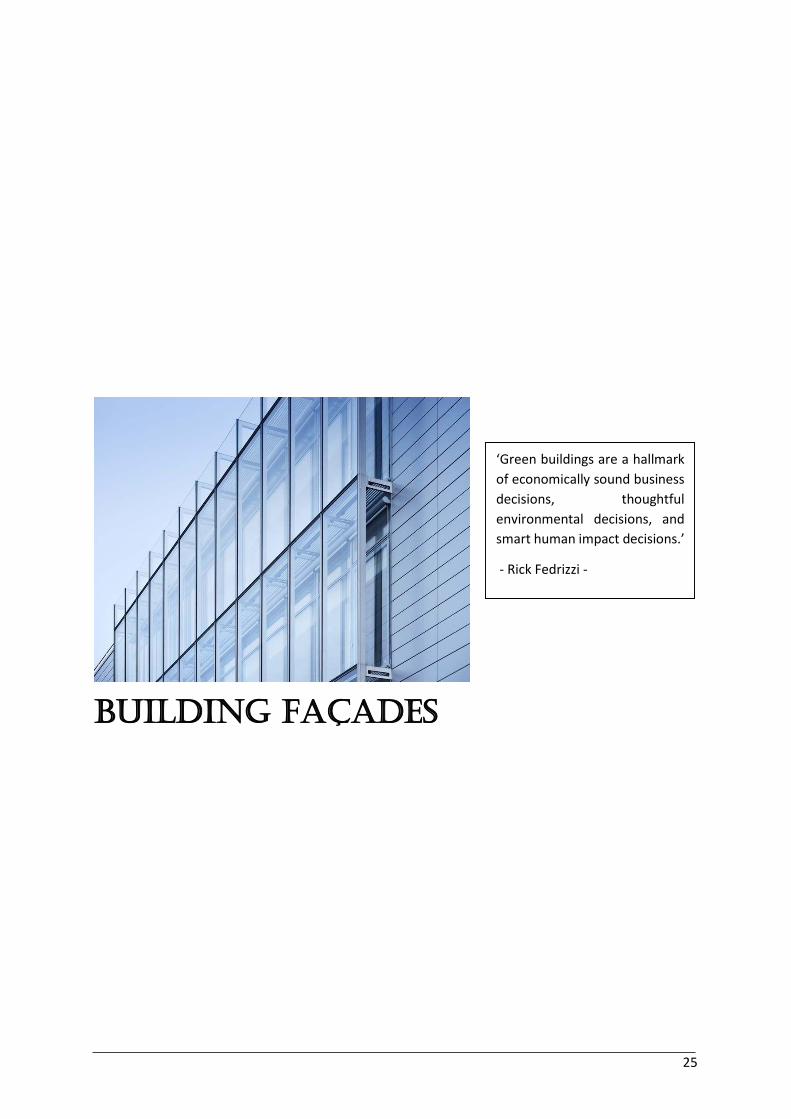
25
Building Façades
‘Green buildings are a hallmark
of economically sound business
decisions, thoughtful
environmental decisions, and
smart human impact decisions.’
- Rick Fedrizzi -

3.1 Introduction 26
3 Building façades 3.1 Introduction
All history long, people have searched for building and living conditions to make life comfortable
through the seasonal weather changes. The last century and more specific the last decades, the world
population keeps on growing significantly and the global warming and climate change form a challenge
for our planet. The current trend is to build higher buildings on a smaller surface which enables people
to live more concentrated. To obtain a good performance in combination with an efficient energy use
for mid/high-rise buildings, new building methods are developed.
Façades of commercial buildings and high-rise buildings in general, contain mostly large amounts of
glass. Such façade configurations can result in significant heat losses or heat gains depending on the
season. The creation of highly glazed façades with an excellent performance is a complex challenge for
which still a lot of tools, technologies, processes and databases are missing. Using a second layer that
accommodates the first one can contribute to an improved performance. One option is to place a kind
of curtain in front of the wall. Another possibility is to use a second layer of glass or other opaque
materials, which is called a double façade.
When a façade is built, some functional requirements need to be fulfilled. First of all, some essential
requirements are important such as the tightness, fire safety, maintenance and repair … In addition,
the design of an advanced façade tries to achieve improved indoor air quality, energy efficiency,
thermal performance and occupant comfort by concepts such as ventilation systems, shading systems
for sun control, the regulation of daylight and acoustic insulation. This optimisation of the building
façade decreases the heating, cooling and lighting load of the building. The most difficult aspect for
the design is to combine several strategies together.
The design of a façade has to respect the location of the building as well. Different geographical
locations have different climate characteristics with other primary requirements. An increased internal
comfort (better air quality, thermal comfort …) results in a better occupant health in combination with
a better productivity and amenities for the occupants. Also, the current problems of running out of
resources of raw materials and increasing costs of materials make the demand for innovating concepts
that minimise the use of energy and material consumption more pressing. The purposes of advanced
façades to reduce overall energy use and environmental impacts can only be achieved when these
different aspects are respected (Lee et al., 2002).
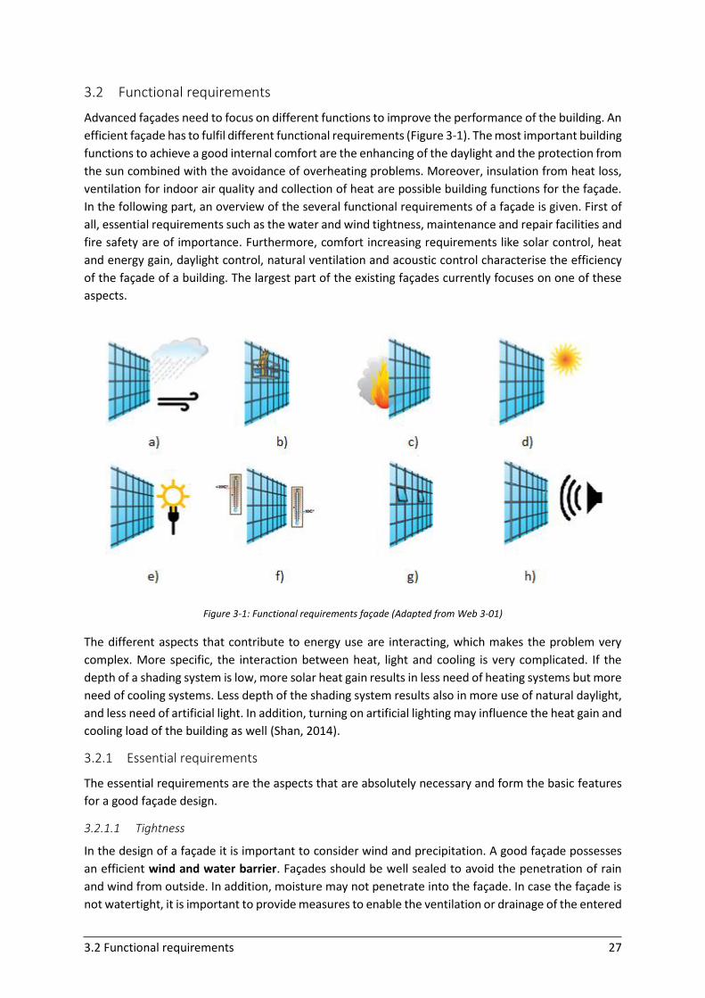
3.2 Functional requirements 27
3.2 Functional requirements
Advanced façades need to focus on different functions to improve the performance of the building. An
efficient façade has to fulfil different functional requirements (Figure 3-1). The most important building
functions to achieve a good internal comfort are the enhancing of the daylight and the protection from
the sun combined with the avoidance of overheating problems. Moreover, insulation from heat loss,
ventilation for indoor air quality and collection of heat are possible building functions for the façade.
In the following part, an overview of the several functional requirements of a façade is given. First of
all, essential requirements such as the water and wind tightness, maintenance and repair facilities and
fire safety are of importance. Furthermore, comfort increasing requirements like solar control, heat
and energy gain, daylight control, natural ventilation and acoustic control characterise the efficiency
of the façade of a building. The largest part of the existing façades currently focuses on one of these
aspects.
Figure 3-1: Functional requirements façade (Adapted from Web 3-01)
The different aspects that contribute to energy use are interacting, which makes the problem very
complex. More specific, the interaction between heat, light and cooling is very complicated. If the
depth of a shading system is low, more solar heat gain results in less need of heating systems but more
need of cooling systems. Less depth of the shading system results also in more use of natural daylight,
and less need of artificial light. In addition, turning on artificial lighting may influence the heat gain and
cooling load of the building as well (Shan, 2014).
3.2.1 Essential requirements
The essential requirements are the aspects that are absolutely necessary and form the basic features
for a good façade design.
3.2.1.1 Tightness
In the design of a façade it is important to consider wind and precipitation. A good façade possesses
an efficient wind and water barrier. Façades should be well sealed to avoid the penetration of rain
and wind from outside. In addition, moisture may not penetrate into the façade. In case the façade is
not watertight, it is important to provide measures to enable the ventilation or drainage of the entered
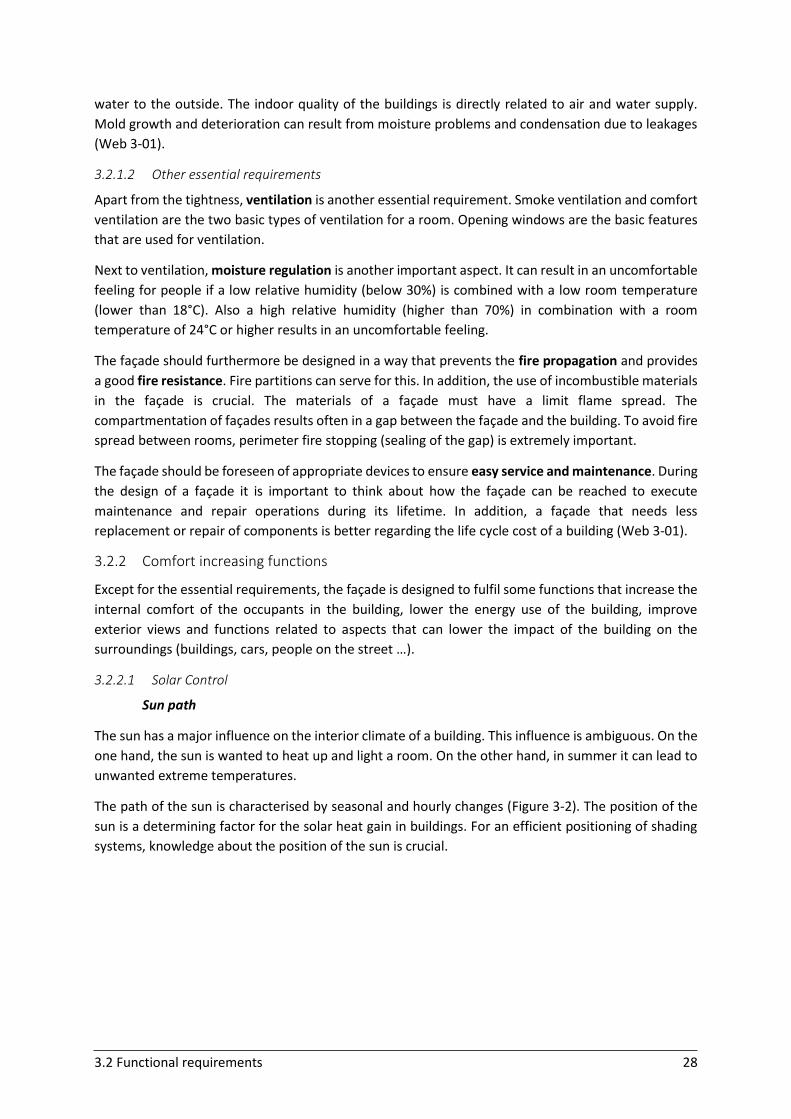
3.2 Functional requirements 28
water to the outside. The indoor quality of the buildings is directly related to air and water supply.
Mold growth and deterioration can result from moisture problems and condensation due to leakages
(Web 3-01).
3.2.1.2 Other essential requirements
Apart from the tightness, ventilation is another essential requirement. Smoke ventilation and comfort
ventilation are the two basic types of ventilation for a room. Opening windows are the basic features
that are used for ventilation.
Next to ventilation, moisture regulation is another important aspect. It can result in an uncomfortable
feeling for people if a low relative humidity (below 30%) is combined with a low room temperature
(lower than 18°C). Also a high relative humidity (higher than 70%) in combination with a room
temperature of 24°C or higher results in an uncomfortable feeling.
The façade should furthermore be designed in a way that prevents the fire propagation and provides
a good fire resistance. Fire partitions can serve for this. In addition, the use of incombustible materials
in the façade is crucial. The materials of a façade must have a limit flame spread. The
compartmentation of façades results often in a gap between the façade and the building. To avoid fire
spread between rooms, perimeter fire stopping (sealing of the gap) is extremely important.
The façade should be foreseen of appropriate devices to ensure easy service and maintenance. During
the design of a façade it is important to think about how the façade can be reached to execute
maintenance and repair operations during its lifetime. In addition, a façade that needs less
replacement or repair of components is better regarding the life cycle cost of a building (Web 3-01).
3.2.2 Comfort increasing functions
Except for the essential requirements, the façade is designed to fulfil some functions that increase the
internal comfort of the occupants in the building, lower the energy use of the building, improve
exterior views and functions related to aspects that can lower the impact of the building on the
surroundings (buildings, cars, people on the street …).
3.2.2.1 Solar Control
Sun path
The sun has a major influence on the interior climate of a building. This influence is ambiguous. On the
one hand, the sun is wanted to heat up and light a room. On the other hand, in summer it can lead to
unwanted extreme temperatures.
The path of the sun is characterised by seasonal and hourly changes (Figure 3-2). The position of the
sun is a determining factor for the solar heat gain in buildings. For an efficient positioning of shading
systems, knowledge about the position of the sun is crucial.
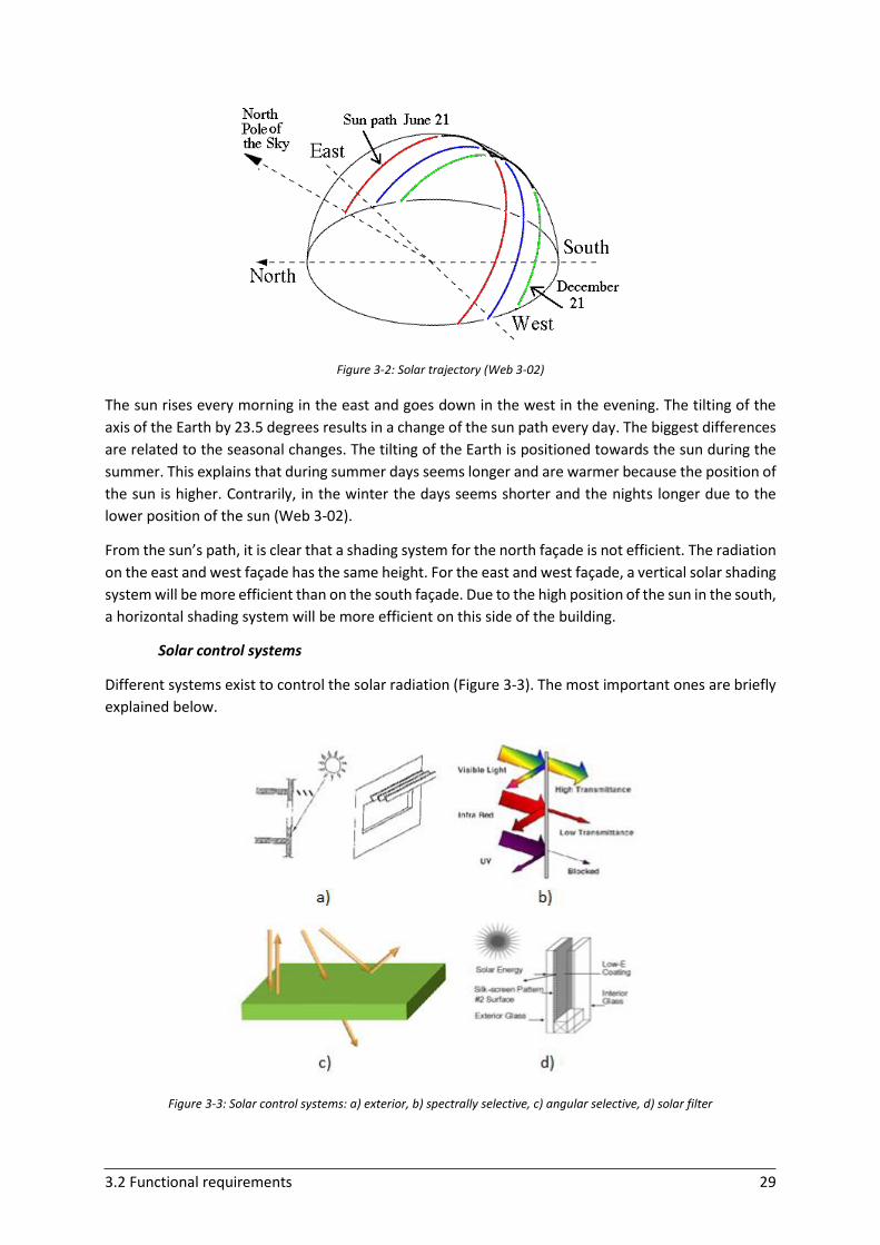
3.2 Functional requirements 29
Figure 3-2: Solar trajectory (Web 3-02)
The sun rises every morning in the east and goes down in the west in the evening. The tilting of the
axis of the Earth by 23.5 degrees results in a change of the sun path every day. The biggest differences
are related to the seasonal changes. The tilting of the Earth is positioned towards the sun during the
summer. This explains that during summer days seems longer and are warmer because the position of
the sun is higher. Contrarily, in the winter the days seems shorter and the nights longer due to the
lower position of the sun (Web 3-02).
From the sun’s path, it is clear that a shading system for the north façade is not efficient. The radiation
on the east and west façade has the same height. For the east and west façade, a vertical solar shading
system will be more efficient than on the south façade. Due to the high position of the sun in the south,
a horizontal shading system will be more efficient on this side of the building.
Solar control systems
Different systems exist to control the solar radiation (Figure 3-3). The most important ones are briefly
explained below.
Figure 3-3: Solar control systems: a) exterior, b) spectrally selective, c) angular selective, d) solar filter
3.2 Functional requirements 30
Exterior solar control
The most well-known solar system is the exterior control of the sun by overhang systems or window
screens. These dynamic systems block direct sun before it enters the building. In contrast to fixed
systems, they can control thermal gain, reduce glare and redirect sunlight and are far more flexible
and efficient. Typical examples are louvers or blinds. These are composed of horizontal or/and vertical
slats. Their most important function is to serve as shading system, but they are able to redirect light as
well (Lee et al., 2002).
Spectrally selective solar control
Spectrally selective glazings are glass systems that in contrast to the common glazings screen out,
absorb or reflect the ultraviolet and infrared radiation which arrives at the building surface. By blocking
this portion of the solar spectrum, the generation of heat diminishes. In general, absorption can still
result in some of the heat that transfers to the interior of the building, which makes reflection more
efficient than the principle of absorption.
The spectrally selective glazings can deal with overheating problems during summer and heat loss
during winter. On the same time, these glazings permit the biggest part of the visible light to enter,
resulting in efficient use of natural daylight as well (Lee et al., 2002).
Angular selective solar control
Another possibility to allow the entering of daylight in combination with blocking or reflecting of
sunlight are angular selective façades. These façades control the solar radiation by a system based on
the angle of the sun. To adjust the blockage angle to the changing position of the sun during the year,
automated control systems can be used.
Besides the traditional systems, another promising idea is to develop coatings that result in angular
solar control. Up till today, no commercial products exist because the design of these angular selective
coatings is not easy and is a challenging future research area (Lee et al., 2002).
Solar filters
Solar filters, made with an opaque or transparent base material, absorb or reflect a portion of both
direct and diffuse solar radiation. The thickness of the filter, the opacity and the reflectance/absorption
play an important role in the effectiveness of the solar control. Solar filters can be placed interior or
exterior (Lee et al., 2002).
3.2.2.2 Daylight control
Besides systems that focus on the control of solar radiation, systems that focus on the control of
daylight are also well-known. By increasing the effective use of natural daylight, reduced artificial
lighting and on the same time improved quality of lighting and visual comfort can be obtained. The
purpose of these systems is to distribute the incoming daylight over the entire room as good as
possible by using principles of reflection, refraction, diffraction and optics.
3.2 Functional requirements 31
Sunlight redirection and sky-light redirection
Light-directing systems are supposed to redirect both direct sunlight and diffuse skylight. In summer,
the sun is high and need to be blocked. In winter, the altitude of the sun is lower and the sun can
penetrate the room. So, seasonal variations in the position of the sun are the basis for the design of
these lighting systems. Systems designed to block sun are often less efficient with respect to
redirection of daylight (Lee et al., 2002).
Sky-light redirection systems are designed to increase the use of daylight and have less attention for
the depth of the light redirection. Systems that work with gathering of diffuse light and guiding this by
using mirrors are well-known (Lee et al., 2002).
Glare
For the visual comfort of the occupants (fatigue, discomfort …) and the surrounding people and
buildings, the control of glare is important. Glare in buildings results from the reflection of light from
the sun on a reflective surface, such as glass. Glare can result in safety risks and can increase the solar
loads on adjacent buildings by reflecting on the glass surfaces. In addition, reflected glare can hit
pedestrians or drivers outside or other buildings in the surroundings and disturb their occupants. Glare
can be efficiently controlled by blinds or louvers (Shih & Huang, 2001).
3.2.2.3 Energy gain/storage
Solar radiation is energy in the form of electromagnetic radiation. The amount of energy that building
envelopes receive, can be used as the energy that is needed to operate the building (Lee et al., 2002)
(Burton, 2012). The quantity that strikes the building’s façade depends on the weather conditions,
location and orientation of the sun.
A recent principle to capture energy is the installation of BIPVs (building-integrated photovoltaics) in
the building’s envelope. Photovoltaics are a form of renewable energy that produce energy on site
directly from the sun. Photovoltaics serve simultaneously as building envelope material and power
generator and provide savings in material and electricity costs which lowers the total life cycle cost of
the building (Web 3-03).
3.2.2.4 Natural ventilation
Fresh air and natural ventilation are important for the internal comfort. Besides the opening of
windows, other systems exist that allow natural ventilation such as the efficient use of the air cavity
between two layers. In general, air movement has a strong influence on the comfort depending on the
situation. When the temperature in a room is high, increased ventilation has a positive influence on
the comfort. In contrast, low temperatures ask for a decrease in ventilation (Van Dijk, 2009).
3.2.2.5 Acoustic control
Most building façades focus on thermal and optical requirements. Recently, the growth in
environmental noise pollution and building high-rise buildings in noisy urban areas, results in acoustic
requirements for the building envelopes as well. For the façades, the control of the outdoor-indoor
transmission of sounds is essential. Walls are exposed to noise sources such as cars, trains, aircrafts …
The mitigation of this outside noise in office buildings is important to increase the acoustic
performance of the work environment. Therefore, the occurrence and propagation of disturbing noise
should be limited.
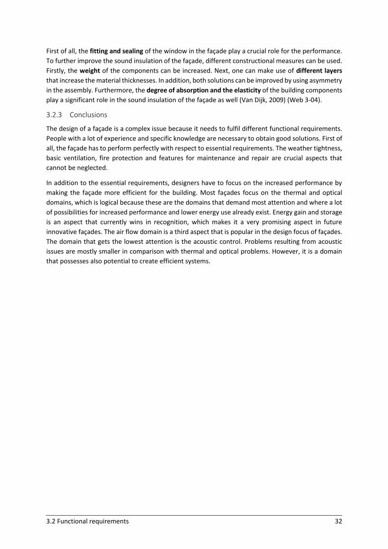
3.2 Functional requirements 32
First of all, the fitting and sealing of the window in the façade play a crucial role for the performance.
To further improve the sound insulation of the façade, different constructional measures can be used.
Firstly, the weight of the components can be increased. Next, one can make use of different layers
that increase the material thicknesses. In addition, both solutions can be improved by using asymmetry
in the assembly. Furthermore, the degree of absorption and the elasticity of the building components
play a significant role in the sound insulation of the façade as well (Van Dijk, 2009) (Web 3-04).
3.2.3 Conclusions
The design of a façade is a complex issue because it needs to fulfil different functional requirements.
People with a lot of experience and specific knowledge are necessary to obtain good solutions. First of
all, the façade has to perform perfectly with respect to essential requirements. The weather tightness,
basic ventilation, fire protection and features for maintenance and repair are crucial aspects that
cannot be neglected.
In addition to the essential requirements, designers have to focus on the increased performance by
making the façade more efficient for the building. Most façades focus on the thermal and optical
domains, which is logical because these are the domains that demand most attention and where a lot
of possibilities for increased performance and lower energy use already exist. Energy gain and storage
is an aspect that currently wins in recognition, which makes it a very promising aspect in future
innovative façades. The air flow domain is a third aspect that is popular in the design focus of façades.
The domain that gets the lowest attention is the acoustic control. Problems resulting from acoustic
issues are mostly smaller in comparison with thermal and optical problems. However, it is a domain
that possesses also potential to create efficient systems.
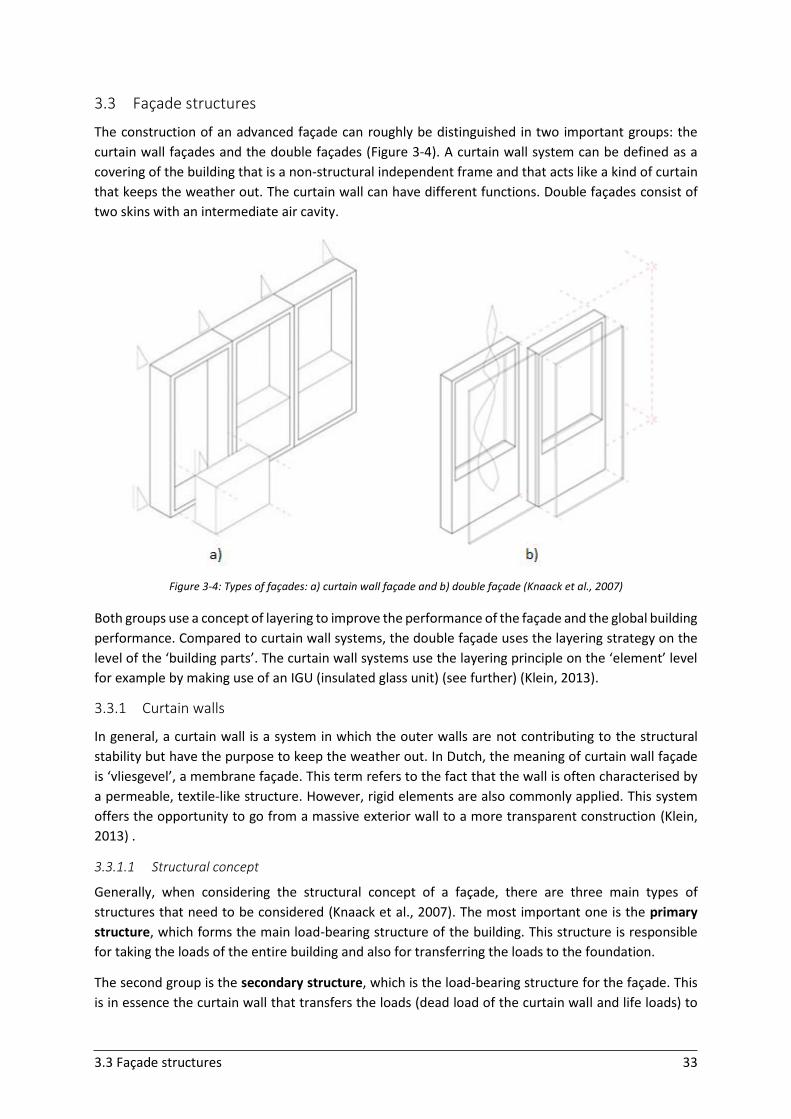
3.3 Façade structures 33
3.3 Façade structures
The construction of an advanced façade can roughly be distinguished in two important groups: the
curtain wall façades and the double façades (Figure 3-4). A curtain wall system can be defined as a
covering of the building that is a non-structural independent frame and that acts like a kind of curtain
that keeps the weather out. The curtain wall can have different functions. Double façades consist of
two skins with an intermediate air cavity.
Figure 3-4: Types of façades: a) curtain wall façade and b) double façade (Knaack et al., 2007)
Both groups use a concept of layering to improve the performance of the façade and the global building
performance. Compared to curtain wall systems, the double façade uses the layering strategy on the
level of the ‘building parts’. The curtain wall systems use the layering principle on the ‘element’ level
for example by making use of an IGU (insulated glass unit) (see further) (Klein, 2013).
3.3.1 Curtain walls
In general, a curtain wall is a system in which the outer walls are not contributing to the structural
stability but have the purpose to keep the weather out. In Dutch, the meaning of curtain wall façade
is ‘vliesgevel’, a membrane façade. This term refers to the fact that the wall is often characterised by
a permeable, textile-like structure. However, rigid elements are also commonly applied. This system
offers the opportunity to go from a massive exterior wall to a more transparent construction (Klein,
2013) .
3.3.1.1 Structural concept
Generally, when considering the structural concept of a façade, there are three main types of
structures that need to be considered (Knaack et al., 2007). The most important one is the primary
structure, which forms the main load-bearing structure of the building. This structure is responsible
for taking the loads of the entire building and also for transferring the loads to the foundation.
The second group is the secondary structure, which is the load-bearing structure for the façade. This
is in essence the curtain wall that transfers the loads (dead load of the curtain wall and life loads) to
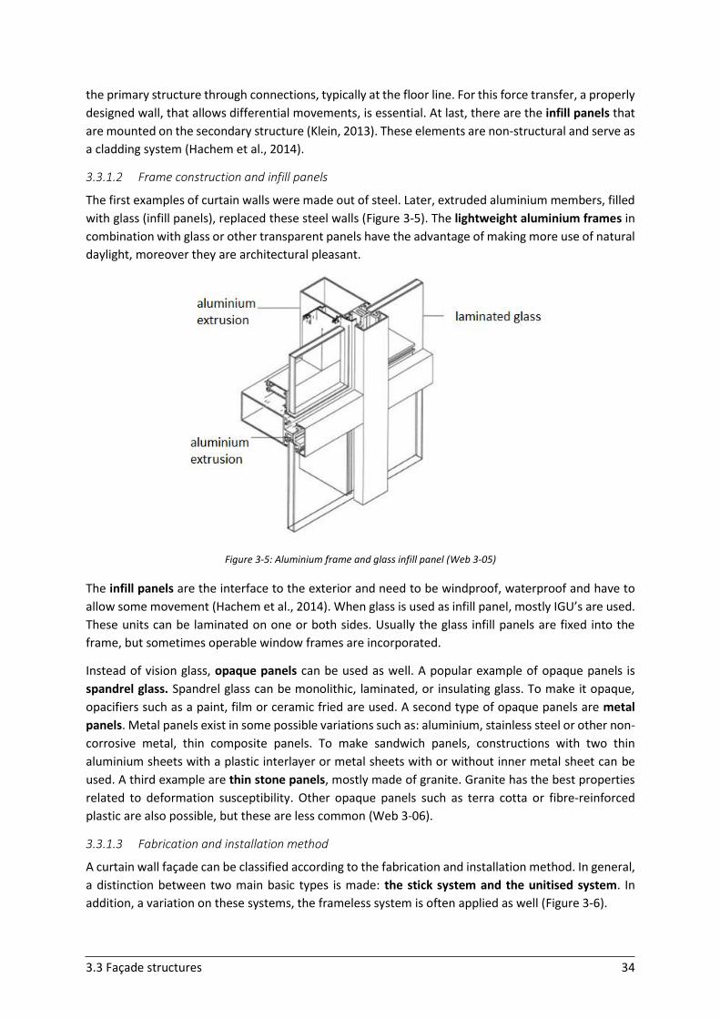
3.3 Façade structures 34
the primary structure through connections, typically at the floor line. For this force transfer, a properly
designed wall, that allows differential movements, is essential. At last, there are the infill panels that
are mounted on the secondary structure (Klein, 2013). These elements are non-structural and serve as
a cladding system (Hachem et al., 2014).
3.3.1.2 Frame construction and infill panels
The first examples of curtain walls were made out of steel. Later, extruded aluminium members, filled
with glass (infill panels), replaced these steel walls (Figure 3-5). The lightweight aluminium frames in
combination with glass or other transparent panels have the advantage of making more use of natural
daylight, moreover they are architectural pleasant.
Figure 3-5: Aluminium frame and glass infill panel (Web 3-05)
The infill panels are the interface to the exterior and need to be windproof, waterproof and have to
allow some movement (Hachem et al., 2014). When glass is used as infill panel, mostly IGU’s are used.
These units can be laminated on one or both sides. Usually the glass infill panels are fixed into the
frame, but sometimes operable window frames are incorporated.
Instead of vision glass, opaque panels can be used as well. A popular example of opaque panels is
spandrel glass. Spandrel glass can be monolithic, laminated, or insulating glass. To make it opaque,
opacifiers such as a paint, film or ceramic fried are used. A second type of opaque panels are metal
panels. Metal panels exist in some possible variations such as: aluminium, stainless steel or other non-
corrosive metal, thin composite panels. To make sandwich panels, constructions with two thin
aluminium sheets with a plastic interlayer or metal sheets with or without inner metal sheet can be
used. A third example are thin stone panels, mostly made of granite. Granite has the best properties
related to deformation susceptibility. Other opaque panels such as terra cotta or fibre-reinforced
plastic are also possible, but these are less common (Web 3-06).
3.3.1.3 Fabrication and installation method
A curtain wall façade can be classified according to the fabrication and installation method. In general,
a distinction between two main basic types is made: the stick system and the unitised system. In
addition, a variation on these systems, the frameless system is often applied as well (Figure 3-6).
3.3 Façade structures 35
Figure 3-6: Overview curtain wall systems: a) stick, b) unitised, c) frameless (Klein, 2013) (Knaack et al., 2007)
The stick system and the unitised system can be designed as interior or exterior glazed systems. The
choice between interior or exterior glazed systems depends on different aspects. When glazing or
opaque panels form the interior side, air infiltration can happen. Interior glazed systems are only used
in specific applications in which the interior of the curtain wall is obstructed as limited as possible.
These systems allow adequate access. For exterior glazed systems, the repair and the replacement of
parts of the structure are not easy. For the maintenance, swing stages or scaffolding are required (Web
3-06).
Stick system
The majority of curtain walls follow the stick system. This system is based on the installation of long
pieces, called sticks. These sticks are a more developed manner to build the façades than by using
craftsmanship (Hachem et al., 2014). The stick pieces are installed one by one on site with the panels
inserted into the frame. The pieces are installed between floors in a vertical way and/or between
vertical members in a horizontal way.
The structural support for the curtain wall construction is ensured by a framework of mullions and
transoms that form the façade substructure. The mullions transfer the forces due to dead load and
wind load. Furthermore they provide support for the cladding. The mullions are mostly storey-high
vertical elements that are linked by the transoms. Transoms are horizontal structural elements that
transfer wind loads and the weight of the panels to the main load-bearing, primary structure. The
mullions and transoms are in literature also called posts and beams, which results in an alternative
name: post-and-beam façade (= mullion-transom façade) (Figure 3-7). Two important variations on
these façades are possible, more specifically the post façade and the beam façade (Sommer, 2010).
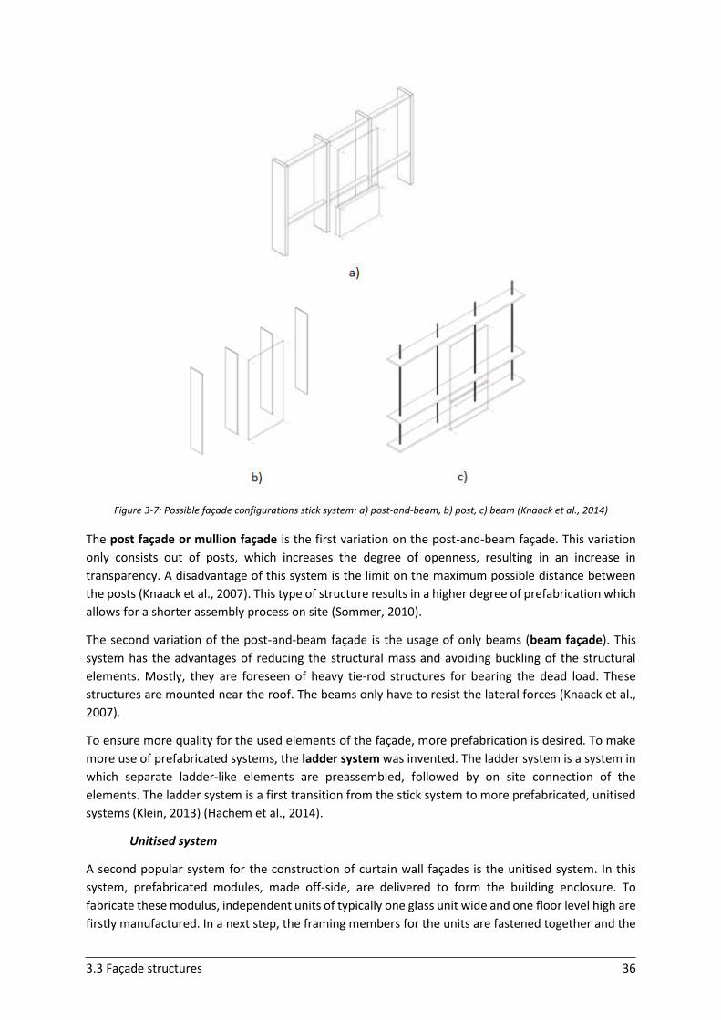
3.3 Façade structures 36
Figure 3-7: Possible façade configurations stick system: a) post-and-beam, b) post, c) beam (Knaack et al., 2014)
The post façade or mullion façade is the first variation on the post-and-beam façade. This variation
only consists out of posts, which increases the degree of openness, resulting in an increase in
transparency. A disadvantage of this system is the limit on the maximum possible distance between
the posts (Knaack et al., 2007). This type of structure results in a higher degree of prefabrication which
allows for a shorter assembly process on site (Sommer, 2010).
The second variation of the post-and-beam façade is the usage of only beams (beam façade). This
system has the advantages of reducing the structural mass and avoiding buckling of the structural
elements. Mostly, they are foreseen of heavy tie-rod structures for bearing the dead load. These
structures are mounted near the roof. The beams only have to resist the lateral forces (Knaack et al.,
2007).
To ensure more quality for the used elements of the façade, more prefabrication is desired. To make
more use of prefabricated systems, the ladder system was invented. The ladder system is a system in
which separate ladder-like elements are preassembled, followed by on site connection of the
elements. The ladder system is a first transition from the stick system to more prefabricated, unitised
systems (Klein, 2013) (Hachem et al., 2014).
Unitised system
A second popular system for the construction of curtain wall façades is the unitised system. In this
system, prefabricated modules, made off-side, are delivered to form the building enclosure. To
fabricate these modulus, independent units of typically one glass unit wide and one floor level high are
firstly manufactured. In a next step, the framing members for the units are fastened together and the
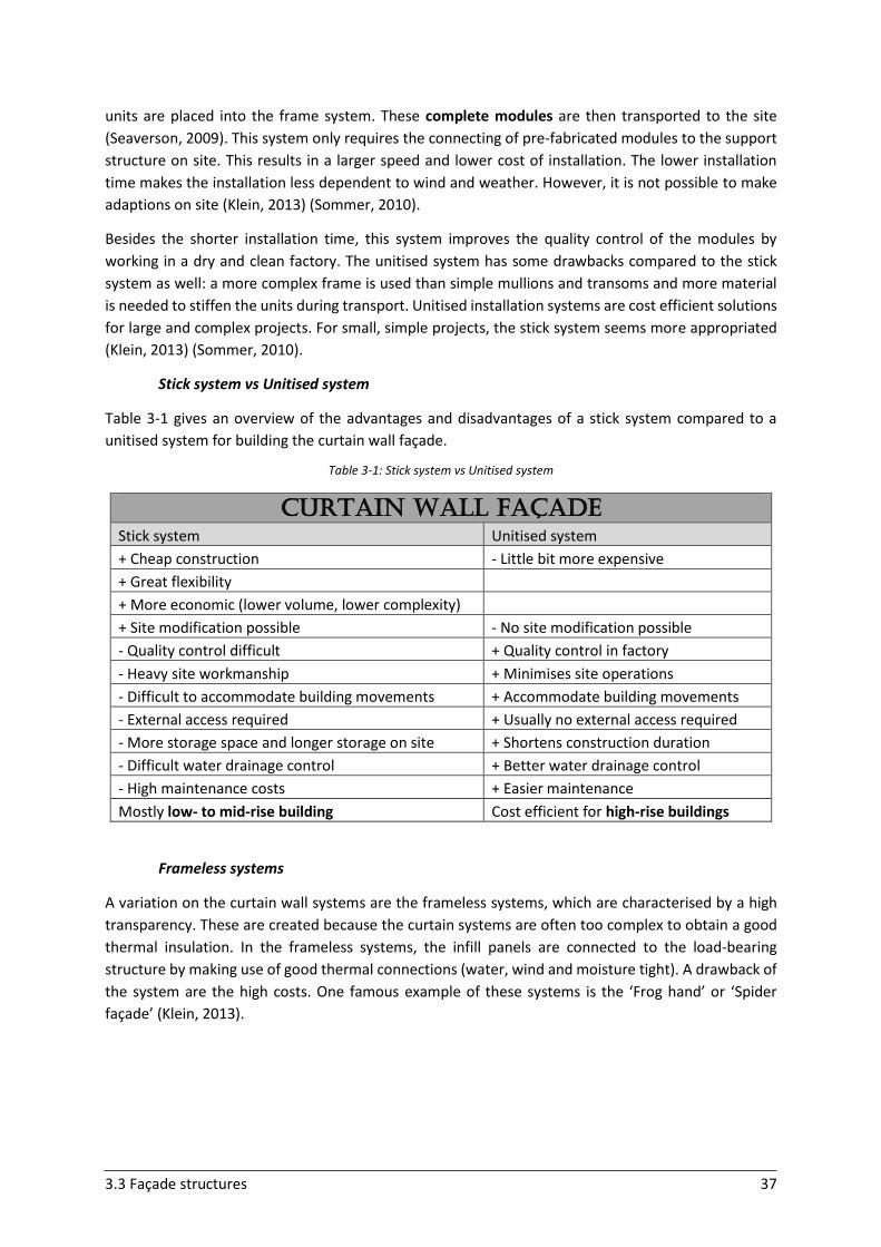
3.3 Façade structures 37
units are placed into the frame system. These complete modules are then transported to the site
(Seaverson, 2009). This system only requires the connecting of pre-fabricated modules to the support
structure on site. This results in a larger speed and lower cost of installation. The lower installation
time makes the installation less dependent to wind and weather. However, it is not possible to make
adaptions on site (Klein, 2013) (Sommer, 2010).
Besides the shorter installation time, this system improves the quality control of the modules by
working in a dry and clean factory. The unitised system has some drawbacks compared to the stick
system as well: a more complex frame is used than simple mullions and transoms and more material
is needed to stiffen the units during transport. Unitised installation systems are cost efficient solutions
for large and complex projects. For small, simple projects, the stick system seems more appropriated
(Klein, 2013) (Sommer, 2010).
Stick system vs Unitised system
Table 3-1 gives an overview of the advantages and disadvantages of a stick system compared to a
unitised system for building the curtain wall façade.
Table 3-1: Stick system vs Unitised system
CURTAIN WALL façade
Stick system Unitised system
+ Cheap construction - Little bit more expensive
+ Great flexibility
+ More economic (lower volume, lower complexity)
+ Site modification possible - No site modification possible
- Quality control difficult + Quality control in factory
- Heavy site workmanship + Minimises site operations
- Difficult to accommodate building movements + Accommodate building movements
- External access required + Usually no external access required
- More storage space and longer storage on site + Shortens construction duration
- Difficult water drainage control + Better water drainage control
- High maintenance costs + Easier maintenance
Mostly low- to mid-rise building Cost efficient for high-rise buildings
Frameless systems
A variation on the curtain wall systems are the frameless systems, which are characterised by a high
transparency. These are created because the curtain systems are often too complex to obtain a good
thermal insulation. In the frameless systems, the infill panels are connected to the load-bearing
structure by making use of good thermal connections (water, wind and moisture tight). A drawback of
the system are the high costs. One famous example of these systems is the ‘Frog hand’ or ‘Spider
façade’ (Klein, 2013).
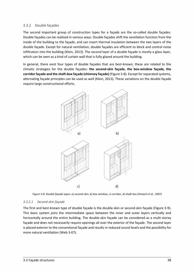
3.3 Façade structures 38
3.3.2 Double façades
The second important group of construction types for a façade are the so-called double façades.
Double façades can be realised in various ways. Double façades shift the ventilation function from the
inside of the building to the façade, and can insert thermal insulation between the two layers of the
double façade. Except for natural ventilation, double façades are efficient to block and control noise
infiltration into the building (Klein, 2013). The second layer of a double façade is mostly a glass layer,
which can be seen as a kind of curtain wall that is fully glazed around the building.
In general, there exist four types of double façades that are best-known, these are related to the
climatic strategies for the double façades: the second-skin façade, the box-window façade, the
corridor façade and the shaft-box façade (chimney façade) (Figure 3-8). Except for separated systems,
alternating façade principles can be used as well (Klein, 2013). These variations on the double façade
require large constructional efforts.
Figure 3-8: Double façade types: a) second-skin, b) box-window, c) corridor, d) shaft-box (Knaack et al., 2007)
3.3.2.1 Second-skin façade
The first and best-known type of double façade is the double-skin or second-skin façade (Figure 3-9).
This basic system joins the intermediate space between the inner and outer layers vertically and
horizontally around the entire building. The double-skin façade can be considered as a multi-storey
façade and does not necessarily require openings all over the exterior of the façade. The second layer
is placed exterior to the conventional façade and results in reduced sound levels and the possibility for
more natural ventilation (Web 3-07).
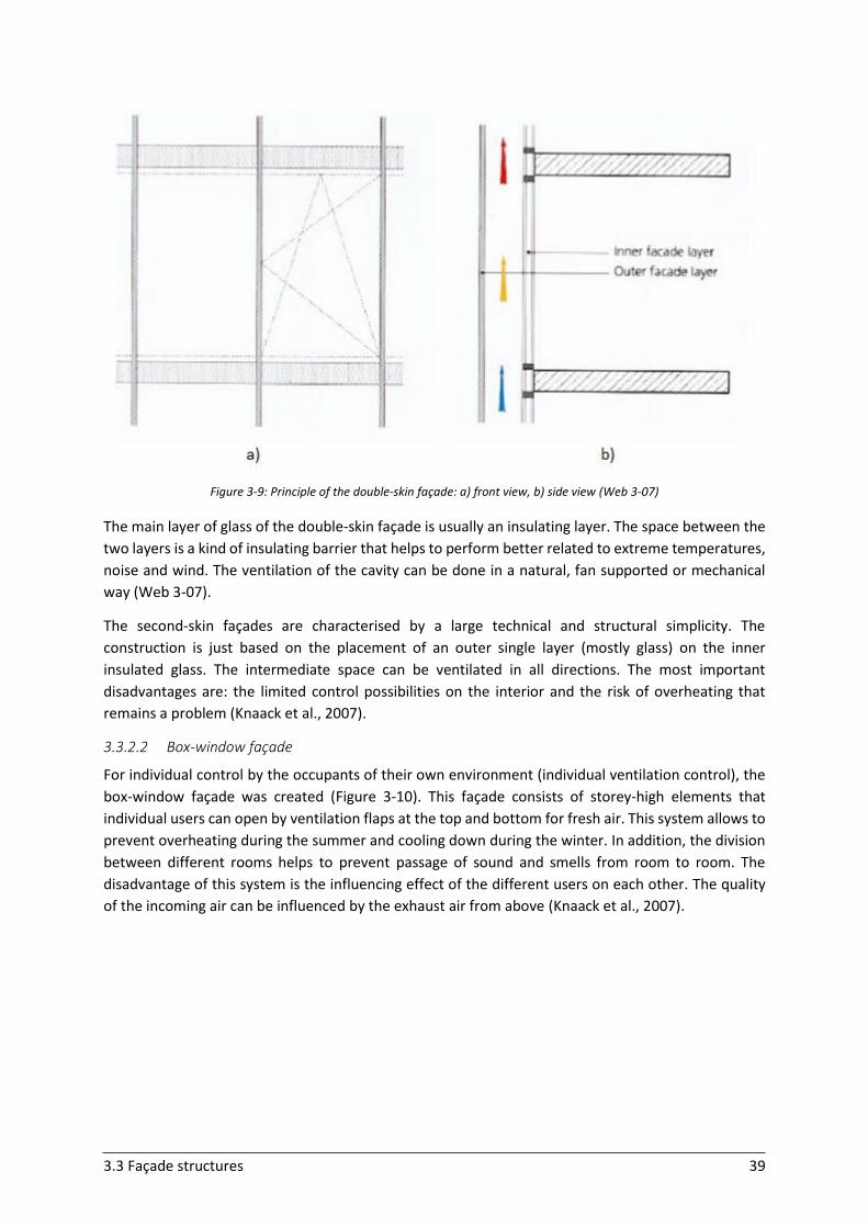
3.3 Façade structures 39
Figure 3-9: Principle of the double-skin façade: a) front view, b) side view (Web 3-07)
The main layer of glass of the double-skin façade is usually an insulating layer. The space between the
two layers is a kind of insulating barrier that helps to perform better related to extreme temperatures,
noise and wind. The ventilation of the cavity can be done in a natural, fan supported or mechanical
way (Web 3-07).
The second-skin façades are characterised by a large technical and structural simplicity. The
construction is just based on the placement of an outer single layer (mostly glass) on the inner
insulated glass. The intermediate space can be ventilated in all directions. The most important
disadvantages are: the limited control possibilities on the interior and the risk of overheating that
remains a problem (Knaack et al., 2007).
3.3.2.2 Box-window façade
For individual control by the occupants of their own environment (individual ventilation control), the
box-window façade was created (Figure 3-10). This façade consists of storey-high elements that
individual users can open by ventilation flaps at the top and bottom for fresh air. This system allows to
prevent overheating during the summer and cooling down during the winter. In addition, the division
between different rooms helps to prevent passage of sound and smells from room to room. The
disadvantage of this system is the influencing effect of the different users on each other. The quality
of the incoming air can be influenced by the exhaust air from above (Knaack et al., 2007).
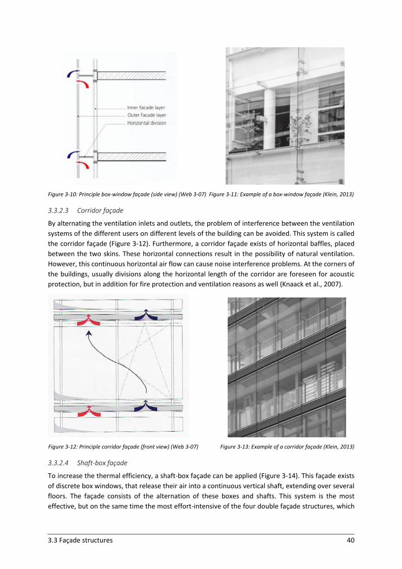
3.3 Façade structures 40
Figure 3-10: Principle box-window façade (side view) (Web 3-07) Figure 3-11: Example of a box-window façade (Klein, 2013)
3.3.2.3 Corridor façade
By alternating the ventilation inlets and outlets, the problem of interference between the ventilation
systems of the different users on different levels of the building can be avoided. This system is called
the corridor façade (Figure 3-12). Furthermore, a corridor façade exists of horizontal baffles, placed
between the two skins. These horizontal connections result in the possibility of natural ventilation.
However, this continuous horizontal air flow can cause noise interference problems. At the corners of
the buildings, usually divisions along the horizontal length of the corridor are foreseen for acoustic
protection, but in addition for fire protection and ventilation reasons as well (Knaack et al., 2007).
Figure 3-12: Principle corridor façade (front view) (Web 3-07) Figure 3-13: Example of a corridor façade (Klein, 2013)
3.3.2.4 Shaft-box façade
To increase the thermal efficiency, a shaft-box façade can be applied (Figure 3-14). This façade exists
of discrete box windows, that release their air into a continuous vertical shaft, extending over several
floors. The façade consists of the alternation of these boxes and shafts. This system is the most
effective, but on the same time the most effort-intensive of the four double façade structures, which
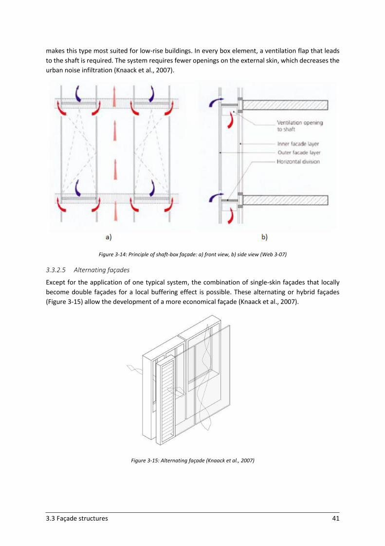
3.3 Façade structures 41
makes this type most suited for low-rise buildings. In every box element, a ventilation flap that leads
to the shaft is required. The system requires fewer openings on the external skin, which decreases the
urban noise infiltration (Knaack et al., 2007).
Figure 3-14: Principle of shaft-box façade: a) front view, b) side view (Web 3-07)
3.3.2.5 Alternating façades
Except for the application of one typical system, the combination of single-skin façades that locally
become double façades for a local buffering effect is possible. These alternating or hybrid façades
(Figure 3-15) allow the development of a more economical façade (Knaack et al., 2007).
Figure 3-15: Alternating façade (Knaack et al., 2007)
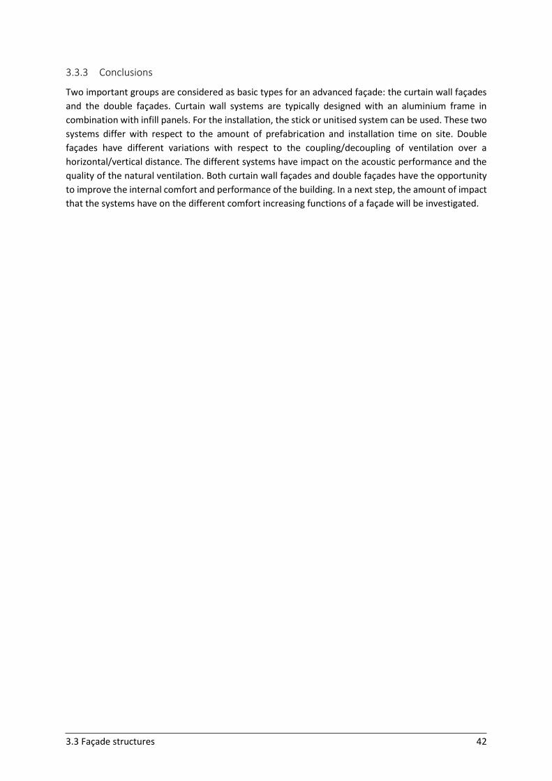
3.3 Façade structures 42
3.3.3 Conclusions
Two important groups are considered as basic types for an advanced façade: the curtain wall façades
and the double façades. Curtain wall systems are typically designed with an aluminium frame in
combination with infill panels. For the installation, the stick or unitised system can be used. These two
systems differ with respect to the amount of prefabrication and installation time on site. Double
façades have different variations with respect to the coupling/decoupling of ventilation over a
horizontal/vertical distance. The different systems have impact on the acoustic performance and the
quality of the natural ventilation. Both curtain wall façades and double façades have the opportunity
to improve the internal comfort and performance of the building. In a next step, the amount of impact
that the systems have on the different comfort increasing functions of a façade will be investigated.
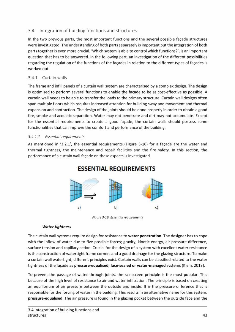
3.4 Integration of building functions and structures 43
3.4 Integration of building functions and structures
In the two previous parts, the most important functions and the several possible façade structures
were investigated. The understanding of both parts separately is important but the integration of both
parts together is even more crucial. ‘Which system is able to control which functions?’, is an important
question that has to be answered. In the following part, an investigation of the different possibilities
regarding the regulation of the functions of the façades in relation to the different types of façades is
worked out.
3.4.1 Curtain walls
The frame and infill panels of a curtain wall system are characterised by a complex design. The design
is optimised to perform several functions to enable the façade to be as cost-effective as possible. A
curtain wall needs to be able to transfer the loads to the primary structure. Curtain wall designs often
span multiple floors which requires increased attention for building sway and movement and thermal
expansion and contraction. The design of the joints should be done properly in order to obtain a good
fire, smoke and acoustic separation. Water may not penetrate and dirt may not accumulate. Except
for the essential requirements to create a good façade, the curtain walls should possess some
functionalities that can improve the comfort and performance of the building.
3.4.1.1 Essential requirements
As mentioned in ‘3.2.1’, the essential requirements (Figure 3-16) for a façade are the water and
thermal tightness, the maintenance and repair facilities and the fire safety. In this section, the
performance of a curtain wall façade on these aspects is investigated.
Figure 3-16: Essential requirements
Water tightness
The curtain wall systems require design for resistance to water penetration. The designer has to cope
with the inflow of water due to five possible forces; gravity, kinetic energy, air pressure difference,
surface tension and capillary action. Crucial for the design of a system with excellent water resistance
is the construction of watertight frame corners and a good drainage for the glazing structure. To make
a curtain wall watertight, different principles exist. Curtain walls can be classified related to the water
tightness of the façade as pressure-equalised, face-sealed or water-managed systems (Klein, 2013).
To prevent the passage of water through joints, the rainscreen principle is the most popular. This
because of the high level of resistance to air and water infiltration. The principle is based on creating
an equilibrium of air pressure between the outside and inside. It is the pressure difference that is
responsible for the forcing of water in the building. This results in an alternative name for this system:
pressure-equalised. The air pressure is found in the glazing pocket between the outside face and the
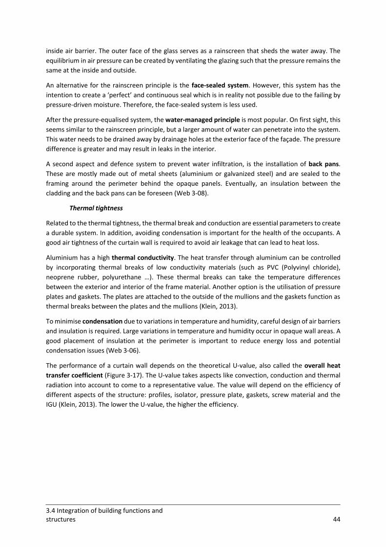
3.4 Integration of building functions and structures 44
inside air barrier. The outer face of the glass serves as a rainscreen that sheds the water away. The
equilibrium in air pressure can be created by ventilating the glazing such that the pressure remains the
same at the inside and outside.
An alternative for the rainscreen principle is the face-sealed system. However, this system has the
intention to create a ‘perfect’ and continuous seal which is in reality not possible due to the failing by
pressure-driven moisture. Therefore, the face-sealed system is less used.
After the pressure-equalised system, the water-managed principle is most popular. On first sight, this
seems similar to the rainscreen principle, but a larger amount of water can penetrate into the system.
This water needs to be drained away by drainage holes at the exterior face of the façade. The pressure
difference is greater and may result in leaks in the interior.
A second aspect and defence system to prevent water infiltration, is the installation of back pans.
These are mostly made out of metal sheets (aluminium or galvanized steel) and are sealed to the
framing around the perimeter behind the opaque panels. Eventually, an insulation between the
cladding and the back pans can be foreseen (Web 3-08).
Thermal tightness
Related to the thermal tightness, the thermal break and conduction are essential parameters to create
a durable system. In addition, avoiding condensation is important for the health of the occupants. A
good air tightness of the curtain wall is required to avoid air leakage that can lead to heat loss.
Aluminium has a high thermal conductivity. The heat transfer through aluminium can be controlled
by incorporating thermal breaks of low conductivity materials (such as PVC (Polyvinyl chloride),
neoprene rubber, polyurethane …). These thermal breaks can take the temperature differences
between the exterior and interior of the frame material. Another option is the utilisation of pressure
plates and gaskets. The plates are attached to the outside of the mullions and the gaskets function as
thermal breaks between the plates and the mullions (Klein, 2013).
To minimise condensation due to variations in temperature and humidity, careful design of air barriers
and insulation is required. Large variations in temperature and humidity occur in opaque wall areas. A
good placement of insulation at the perimeter is important to reduce energy loss and potential
condensation issues (Web 3-06).
The performance of a curtain wall depends on the theoretical U-value, also called the overall heat
transfer coefficient (Figure 3-17). The U-value takes aspects like convection, conduction and thermal
radiation into account to come to a representative value. The value will depend on the efficiency of
different aspects of the structure: profiles, isolator, pressure plate, gaskets, screw material and the
IGU (Klein, 2013). The lower the U-value, the higher the efficiency.
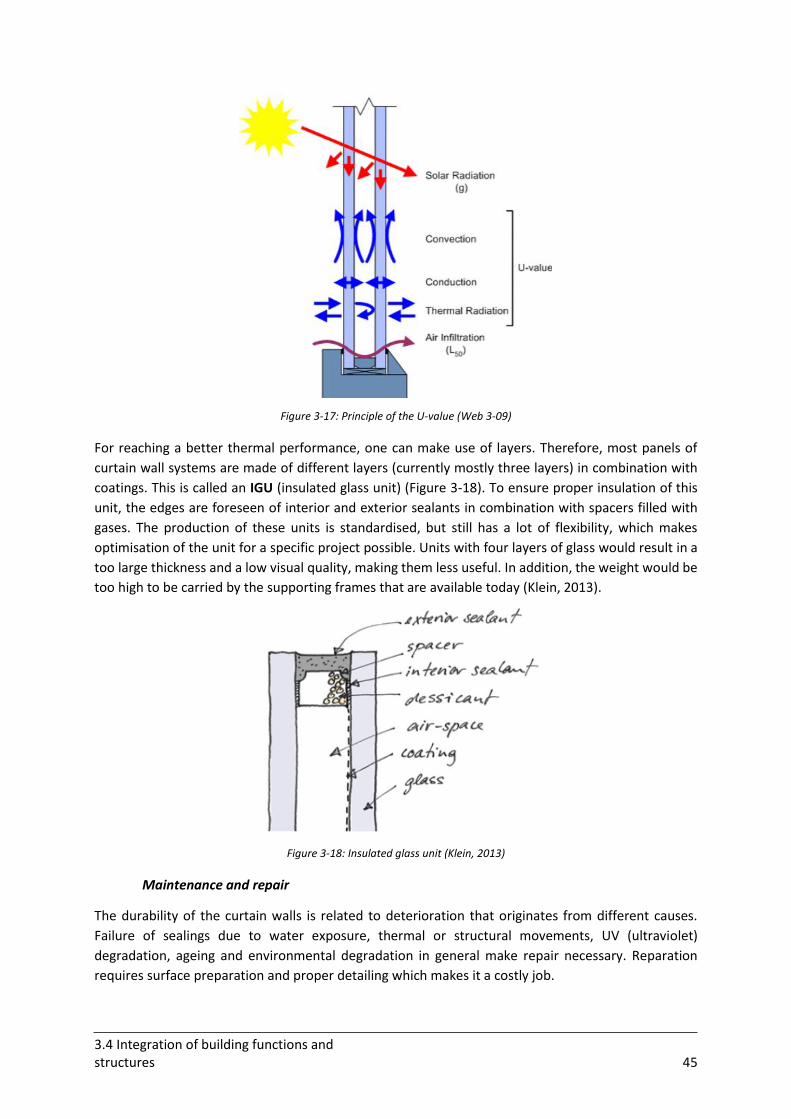
3.4 Integration of building functions and structures 45
Figure 3-17: Principle of the U-value (Web 3-09)
For reaching a better thermal performance, one can make use of layers. Therefore, most panels of
curtain wall systems are made of different layers (currently mostly three layers) in combination with
coatings. This is called an IGU (insulated glass unit) (Figure 3-18). To ensure proper insulation of this
unit, the edges are foreseen of interior and exterior sealants in combination with spacers filled with
gases. The production of these units is standardised, but still has a lot of flexibility, which makes
optimisation of the unit for a specific project possible. Units with four layers of glass would result in a
too large thickness and a low visual quality, making them less useful. In addition, the weight would be
too high to be carried by the supporting frames that are available today (Klein, 2013).
Figure 3-18: Insulated glass unit (Klein, 2013)
Maintenance and repair
The durability of the curtain walls is related to deterioration that originates from different causes.
Failure of sealings due to water exposure, thermal or structural movements, UV (ultraviolet)
degradation, ageing and environmental degradation in general make repair necessary. Reparation
requires surface preparation and proper detailing which makes it a costly job.
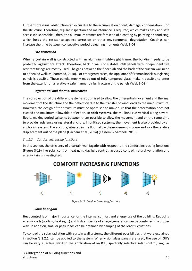
3.4 Integration of building functions and structures 46
Furthermore visual obstruction can occur due to the accumulation of dirt, damage, condensation … on
the structure. Therefore, regular inspection and maintenance is required, which makes easy and safe
access indispensable. Often, the aluminium frames are foreseen of a coating by painting or anodising,
which helps the resistance against corrosion or other environmental degradation. Coatings can
increase the time between consecutive periodic cleaning moments (Web 3-08).
Fire protection
When a curtain wall is constructed with an aluminium lightweight frame, the building needs to be
protected against fire attack. Therefore, backup walls or suitable infill panels with independent fire
resistant fixings are mostly used. The gaps between the floor slab and the back of the curtain wall need
to be sealed well (Muhammad, 2010). For emergency cases, the appliance of fireman knock-out glazing
panels is possible. These panels, mostly made out of fully tempered glass, make it possible to enter
from the exterior on a relatively safe manner by full fracture of the panels (Web 3-08).
Differential and thermal movement
The construction of the different systems is optimised to allow the differential movement and thermal
movement of the structure and the deflection due to the transfer of wind loads to the main structure.
However, the design of the structure must be optimised to make sure that the deformation does not
exceed the maximum allowable deflection. In stick systems, the mullions run vertical along several
floors, making periodical splits between them possible to allow the movement and on the same time
to provide resistance using lateral anchors. In unitised systems, the movement is also provided by an
anchoring system. The anchors, situated in the floor, allow the movement in plane and lock the relative
displacement out of the plane (Hachem et al., 2014) (Kassem & Mitchell, 2015).
3.4.1.2 Comfort increasing functions
In this section, the efficiency of a curtain wall façade with respect to the comfort increasing functions
(Figure 3-19) like solar control, heat gain, daylight control, acoustic control, natural ventilation and
energy gain is investigated.
Figure 3-19: Comfort increasing functions
Solar heat gain
Heat control is of major importance for the internal comfort and energy use of the building. Reducing
energy loads (cooling, heating ...) and high efficiency of energy generation can be combined in a proper
way. In addition, smaller peak loads can be obtained by damping of the load fluctuations.
To control the solar radiation with curtain wall systems, the different possibilities that were explained
in section ‘3.2.2.1’ can be applied to the system. When vision glass panels are used, the use of IGU’s
can be very effective. Next to the application of an IGU, spectrally selective solar control, angular
3.4 Integration of building functions and structures 47
selective solar control, solar filters and exterior solar control are all systems that can make a curtain
wall system more efficient. Reflective glass can be used to keep solar rays out of the building and to
prevent unwanted heat gain. Coatings can be efficient to retain a certain amount of heat to warm the
building during nights and winters (Muhammad, 2010). Another efficient system for controlling the
solar radiation is making use of a solar dynamic buffer zone in the curtain wall systems. In this buffer
zone, solar energy can be efficiently gathered or excluded by making use of air flow (Li et al., 2015).
Daylight control and visual aspects
Using glass as infill panel for the ‘curtain wall’ results in the penetration of natural light deeper in the
building. The problem with glass or other used infill panels is the complexity to combine the control of
thermal and visual comfort (Web 3-10).
Essential for the entering of daylight through a façade is the transparency of the panels. Variation of
the proportion of opaque distribution has an effect on the light distribution and also on the heating
and cooling loads and daylight illuminance. If photovoltaics are integrated in the façade (see below:
energy gain), the regulation of the light transmission can be adjusted by changing the spatial
distribution between the photovoltaic cells. For a good optical performance, mostly semi-transparent
photovoltaic panels are used (Web 3-08).
Glass is the key factor when considering visual features, but sightlines are essential as well. The visual
comfort is directly related to the vertical and horizontal mullions that define the sightlines of the
curtain wall panels. These sightlines are related to the depth and width of the frame. The lateral load
resistance of the frame is also related to the depth. The depth requirements depend on the wind loads
and spans. Narrow sightlines are better for the visual comfort. To reach the necessary lateral load
resistance, steel stiffeners can be used to strengthen the aluminium frame with a smaller depth and
better visual performance (Web 3-06).
Glare
Reflected glare is a significant problem for curtain wall systems, directly related to the used material.
The amount of glare depends on the geographic location of the project (orientation, climate …). When
reflective glass is used to obtain reduced penetration of solar radiation, exterior reflections can have
a negative impact on the environment. Highly reflective glazings can result in 20-40% of reflectance
(Web 3-11). The tilt angles and the orientation of the panels can efficiently reduce the effect of
reflected glare on the neighbourhood (Shih & Huang, 2001).
Acoustic performance
The acoustic performance of a curtain wall façade is a bit dubious. Curtain wall façades are normally
designed to be as lightweight as possible. However the sound transmission is inversely proportional to
the mass of the barrier. So, for sound insulation, a more heavy construction is favourable. The infill
panels mainly determine the acoustic performance of the curtain wall, therefore double glazing is
usually essential. Apart from double glazing, laminated glass layers that exist of a noise-reducing
interlayer (polyvinyl butyral) or other sound attenuating infills can be used (Web 3-08). Furthermore,
varying with the thicknesses of the glass layer in an IGU can reduce the infiltration of exterior noise as
well. For the acoustic performance, the air tightness of the system is also of main importance (Kassem
& Mitchell, 2015).
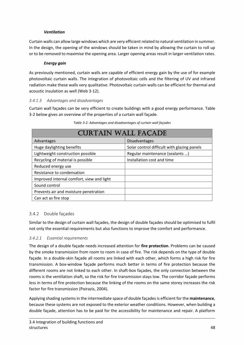
3.4 Integration of building functions and structures 48
Ventilation
Curtain walls can allow large windows which are very efficient related to natural ventilation in summer.
In the design, the opening of the windows should be taken in mind by allowing the curtain to roll up
or to be removed to maximise the opening area. Larger opening areas result in larger ventilation rates.
Energy gain
As previously mentioned, curtain walls are capable of efficient energy gain by the use of for example
photovoltaic curtain walls. The integration of photovoltaic cells and the filtering of UV and infrared
radiation make these walls very qualitative. Photovoltaic curtain walls can be efficient for thermal and
acoustic insulation as well (Web 3-12).
3.4.1.3 Advantages and disadvantages
Curtain wall façades can be very efficient to create buildings with a good energy performance. Table
3-2 below gives an overview of the properties of a curtain wall façade.
Table 3-2: Advantages and disadvantages of curtain wall façades
Curtain wall façade
Advantages Disadvantages
Huge daylighting benefits Solar control difficult with glazing panels
Lightweight construction possible Regular maintenance (sealants …)
Recycling of material is possible Installation cost and time
Reduced energy use
Resistance to condensation
Improved internal comfort, view and light
Sound control
Prevents air and moisture penetration
Can act as fire stop
3.4.2 Double façades
Similar to the design of curtain wall façades, the design of double façades should be optimised to fulfil
not only the essential requirements but also functions to improve the comfort and performance.
3.4.2.1 Essential requirements
The design of a double façade needs increased attention for fire protection. Problems can be caused
by the smoke transmission from room to room in case of fire. The risk depends on the type of double
façade. In a double-skin façade all rooms are linked with each other, which forms a high risk for fire
transmission. A box-window façade performs much better in terms of fire protection because the
different rooms are not linked to each other. In shaft-box façades, the only connection between the
rooms is the ventilation shaft, so the risk for fire transmission stays low. The corridor façade performs
less in terms of fire protection because the linking of the rooms on the same storey increases the risk
factor for fire transmission (Poirazis, 2004).
Applying shading systems in the intermediate space of double façades is efficient for the maintenance,
because these systems are not exposed to the exterior weather conditions. However, when building a
double façade, attention has to be paid for the accessibility for maintenance and repair. A platform
3.4 Integration of building functions and structures 49
can be used to reach the interior space for cleaning. If there are shading systems in the cavity, they
must be able to be moved to facilitate access. In buildings that make use of more divided air cavities
(corridor, shaft-box, box-window façades), the interior panel layer can be used as access panel to enter
the space (Boake et al., 2003).
3.4.2.2 Comfort increasing functions
The double façades are mostly optimised to have efficient performance with respect to ventilation and
the control of solar radiation (Lee et al., 2002). If occupants are able to control light penetration by
controlling louvers or other shading devices that are installed in the air cavity, the productivity of the
working people will also be influenced in a positive way. In addition, the regulation of air movement
and temperature is possible with operable windows, which has a positive influence on the health of
the occupants.
Solar heat gain
The primary purpose of a double façade is mostly to reduce the solar heat gain. This to make natural
ventilation or low energy techniques sufficient for a good interior comfort. External shading elements
are very efficient to reduce solar gain, but they decrease the exterior views and have complex
maintenance requirements. Therefore, double façades with intermediate shading systems are often
an interesting solution.
Intermediate shading devices help to improve heating and cooling problems. These devices are placed
in the air cavity. This is also called a heat extraction double-skin façade. The shading devices offer
opportunities for heat recovery and heat extraction depending on the situation. Mostly the shading
devices are operable blinds, controlled by the occupants or by sensors. These shading systems are a
kind of vertical shield that is efficient for all solar angles. In addition, they can be raised in case of
cloudy weather conditions. Except for controlling the solar heat gain, the efficient use of daylighting
combined with the maintaining of good exterior views is possible (Boake et al., 2003) (Lee et al., 2002).
The precise position of the shading systems in the intermediate cavity is important because there has
to be adequate room for air circulation on both sides. Inadequate air flow can occur if the system is
placed too close to the inner layer. Mostly the shading systems are positioned in the outer half of the
cavity (Lee et al., 2002) (Poirazis, 2004).
A double-skin façade has the additional advantage that it can reduce the heat losses during winter.
The rate of the heat transfer on the panels is lowered by the increased temperature in the air cavity.
This results in a higher surface temperature of the inside panel. For the winter, thin cavities are the
best because they have the highest efficiency for preheating of the ventilation air due to a higher air
velocity inside (Poirazis, 2004).
During summer, the warm inside air in the cavity can be extracted during ventilation and reduce the
cooling loads of the building. This is based on the stack principle that takes additional heat with the
rising air and acts as a thermal buffer. The stack effect in a double-skin façade is a process that is related
to the air density between the exterior and interior layers of the double-skin. This density increases
due to heat generation from the greenhouse effect (air that enters the building is continuously heated
by solar gains). This increase brings pressure and temperature differences in the space between the
interior and exterior layers. The heated air will rise and escape through the openings at the top and
cooler denser air will enter at lower openings (Web 3-13). The stack effect can be optimised by the use
of vertical divisions (shaft-box façades), which makes division between low and high occupied spaces
possible (Poirazis, 2004). In addition by using ‘spectrally selective glazing’ the light can enter the
3.4 Integration of building functions and structures 50
building while the heat is kept out by only allowing the entering of that part of the sun’s energy that is
useful for daylighting purposes (Lee et al., 2002).
Ventilation
Natural ventilation
Natural ventilation uses air flow to cool and ventilate the space instead of mechanical means. A double
layer creates a layer of air next to the first layer that forms the wall of the building. This creates a buffer
zone which allows occupants to make efficient use of natural ventilation. For a better natural
ventilation the buffer zone can be split up in compartments using the box-window, corridor or shaft-
box façade. This can reduce the heat transfer (but also smoke and noise transfer) from one area to
another area. The box-window façade has the opportunity to open windows for proper natural
ventilation without grouping together of air of different rooms. Corridor façades can be efficient to
maximise natural ventilation as well. These façades possess fresh air and exhaust intakes at every floor.
In shaft-box façades, a number of cavities are grouped into a single shaft. For both corridor and shaft-
box façades, caution should be paid to the mixing of fresh and foul air (Boake et al., 2003) (Poirazis,
2004).
Night-time ventilation
In climates with enough variation in diurnal outdoor temperatures, advantage can be taken to cool
down the thermal mass of the building during night. This to avoid problems with accumulated heat
during the day. Night-time ventilation results in lower indoor temperatures during summer in the
morning and provides thermal comfort and improved air quality. By using this kind of pre-cooling
principle, the need for mechanical air conditioning can be reduced (Lee et al., 2002).
Mixed mode
A good solution is to combine the mechanical active ventilation and cooling with natural passive
ventilation. This combination can improve the indoor air quality and results in mixed-mode or hybrid
ventilation. Mixed mode ventilation is possible in different ways. Firstly, alternating operation and
changeover operation are possible. In addition, concurrent operation, in which both systems work at
the same time is an option as well. To work more efficiently, some buildings are partitioned in zones
where one applies different conditioning strategies (Lee et al., 2002).
Daylighting and glare
The double façade can improve the use of natural daylight by applying the right infill panels such as
glass panels. The transparency of the panels is directly related to the amount of daylight that can enter
the space. The daylight improvement by a double façade is not spectacular. Mostly the daylight
properties are the same as single skin glazed façades. However, the additional skin results in a
reduction of the quantity of light that enters the building. This is compensated by the allowance of
larger areas of glazing in double façades, which increases the amount of daylight that can enter. The
most complex aspect in the design is to combine a transparent façade with a good energy performance
and indoor thermal climate (Poirazis, 2004). When a completely glazed façade would be used, this
would result in excessive glare (and heat) at certain times of the day. To reduce the problem of glare,
solar shading devices can be efficient.
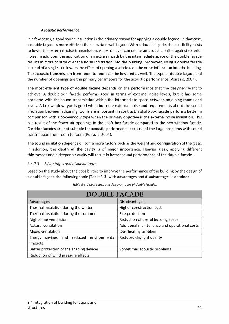
3.4 Integration of building functions and structures 51
Acoustic performance
In a few cases, a good sound insulation is the primary reason for applying a double façade. In that case,
a double façade is more efficient than a curtain wall façade. With a double façade, the possibility exists
to lower the external noise transmission. An extra layer can create an acoustic buffer against exterior
noise. In addition, the application of an extra air path by the intermediate space of the double façade
results in more control over the noise infiltration into the building. Moreover, using a double façade
instead of a single skin lowers the effect of opening a window on the noise infiltration into the building.
The acoustic transmission from room to room can be lowered as well. The type of double façade and
the number of openings are the primary parameters for the acoustic performance (Poirazis, 2004).
The most efficient type of double façade depends on the performance that the designers want to
achieve. A double-skin façade performs good in terms of external noise levels, but it has some
problems with the sound transmission within the intermediate space between adjoining rooms and
levels. A box-window type is good when both the external noise and requirements about the sound
insulation between adjoining rooms are important. In contrast, a shaft-box façade performs better in
comparison with a box-window type when the primary objective is the external noise insulation. This
is a result of the fewer air openings in the shaft-box façade compared to the box-window façade.
Corridor façades are not suitable for acoustic performance because of the large problems with sound
transmission from room to room (Poirazis, 2004).
The sound insulation depends on some more factors such as the weight and configuration of the glass.
In addition, the depth of the cavity is of major importance. Heavier glass, applying different
thicknesses and a deeper air cavity will result in better sound performance of the double façade.
3.4.2.3 Advantages and disadvantages
Based on the study about the possibilities to improve the performance of the building by the design of
a double façade the following table (Table 3-3) with advantages and disadvantages is obtained.
Table 3-3: Advantages and disadvantages of double façades
Double façade
Advantages Disadvantages
Thermal insulation during the winter Higher construction cost
Thermal insulation during the summer Fire protection
Night-time ventilation Reduction of useful building space
Natural ventilation Additional maintenance and operational costs
Mixed ventilation Overheating problem
Energy savings and reduced environmental
impacts
Reduced daylight quality
Better protection of the shading devices Sometimes acoustic problems
Reduction of wind pressure effects
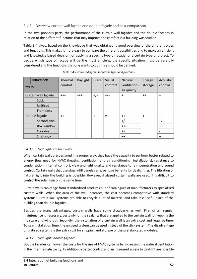
3.4 Integration of building functions and structures 52
3.4.3 Overview curtain wall façade and double façade and cost comparison
In the two previous parts, the performance of the curtain wall façades and the double façades in
relation to the different functions that may improve the comfort in a building was studied.
Table 3-4 gives, based on the knowledge that was obtained, a good overview of the different types
and functions. This makes it more easy to compare the different possibilities and to make an efficient
and knowledge based decision for applying a specific type of façade for a certain type of project. To
decide which type of façade will be the most efficient, the specific situation must be carefully
considered and the functions that one wants to optimise should be defined.
Table 3-4: Overview diagram for façade types and functions
FUNCTIONS Thermal
comfort
Daylight Glare Visual
comfort
Natural
ventilation-
air quality
Energy
storage
Acoustic
control TYPES
Curtain wall façade +++ +++ +/- +/= + ++ +
Stick
Unitised
Frameless
Double façade +++ + + = +++ + ++
Second-skin +/- +/-
Box-window +++ ++
Corridor ++ -
Shaft-box ++ +
3.4.3.1 Highlights curtain walls
When curtain walls are designed in a proper way, they have the capacity to perform better related to
energy (less need for HVAC (heating, ventilation, and air conditioning) installations), resistance to
condensation, internal comfort, view and light quality and resistance to rain penetration and sound
control. Curtain walls that use glass infill panels can give huge benefits for daylighting. The filtration of
natural light into the building is possible. However, if glazed curtain walls are used, it is difficult to
control the solar gain on the same time.
Curtain walls can range from standardised products out of catalogues of manufacturers to specialised
custom walls. When the area of the wall increases, the cost becomes competitive with standard
systems. Curtain wall systems are able to recycle a lot of material and take less useful place of the
building than double façades.
Besides the many advantages, curtain walls have some drawbacks as well. First of all, regular
maintenance is necessary, certainly for the sealants that are applied to the curtain wall for keeping the
moisture and wind out. Secondly, the installation of a curtain wall is an extra cost and requires time.
To gain installation time, the unitised system can be used instead of the stick system. The disadvantage
of unitised systems is the extra cost for shipping and storage of the prefabricated modules.
3.4.3.2 Highlights double façades
Double façades can lower the costs for the use of HVAC systems by increasing the natural ventilation
in the intermediate cavity. In addition, a better control and an increased access to daylight are possible
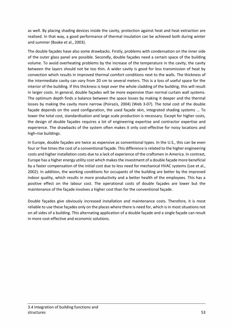
3.4 Integration of building functions and structures 53
as well. By placing shading devices inside the cavity, protection against heat and heat extraction are
realised. In that way, a good performance of thermal insulation can be achieved both during winter
and summer (Boake et al., 2003).
The double façades have also some drawbacks. Firstly, problems with condensation on the inner side
of the outer glass panel are possible. Secondly, double façades need a certain space of the building
volume. To avoid overheating problems by the increase of the temperature in the cavity, the cavity
between the layers should not be too thin. A wider cavity is good for less transmission of heat by
convection which results in improved thermal comfort conditions next to the walls. The thickness of
the intermediate cavity can vary from 20 cm to several meters. This is a loss of useful space for the
interior of the building. If this thickness is kept over the whole cladding of the building, this will result
in larger costs. In general, double façades will be more expensive than normal curtain wall systems.
The optimum depth finds a balance between the space losses by making it deeper and the thermal
losses by making the cavity more narrow (Poirazis, 2004) (Web 3-07). The total cost of the double
façade depends on the used configuration, the used façade skin, integrated shading systems … To
lower the total cost, standardisation and large scale production is necessary. Except for higher costs,
the design of double façades requires a lot of engineering expertise and contractor expertise and
experience. The drawbacks of the system often makes it only cost-effective for noisy locations and
high-rise buildings.
In Europe, double façades are twice as expensive as conventional types. In the U.S., this can be even
four or five times the cost of a conventional façade. This difference is related to the higher engineering
costs and higher installation costs due to a lack of experience of the craftsmen in America. In contrast,
Europe has a higher energy utility cost which makes the investment of a double façade more beneficial
by a faster compensation of the initial cost due to less need for mechanical HVAC systems (Lee et al.,
2002). In addition, the working conditions for occupants of the building are better by the improved
indoor quality, which results in more productivity and a better health of the employees. This has a
positive effect on the labour cost. The operational costs of double façades are lower but the
maintenance of the façade involves a higher cost than for the conventional façade.
Double façades give obviously increased installation and maintenance costs. Therefore, it is most
reliable to use these façades only on the places where there is need for, which is in most situations not
on all sides of a building. This alternating application of a double façade and a single façade can result
in more cost-effective and economic solutions.
3.4 Integration of building functions and structures 54
3.4.4 Orientation of the façade
The different adaption to physical functions for obtaining a good interior comfort (related to day and
night situations) depends on the orientation of the façade. Table 3-5 gives an overview of the
differences between the different orientations and is reflected in plusses and minuses to give the level
of adaption.
Table 3-5: Comparison of the different orientations (Van Dijk, 2009)
This table is interesting in order to know how much the façade should be able to adapt. The term
‘absolute’ refers to the fact that the absolute differences that occur during all seasons are showed and
not for every season separately. The largest level of adaption for daylight and overheating control is
necessary for the south façade. For the east and west façade, this level also has to be significant.
Daylight and overheating control are most effective during summer. The blinding effect of the sun is
higher in winter due to the lower position of the sun. Heat storage can be done during spring/autumn
and summer. Moisture does not necessary needs adaption. The effect of adaptation is lower than for
e.g. thermal insulation. Natural ventilation is especially necessary during summer while in winter,
closure is necessary (Van Dijk, 2009).
3.4 Integration of building functions and structures 55
3.4.5 Conclusions
This chapter investigated the opportunities of the different types of façades to improve the indoor
comfort and performance of the building. Both curtain wall façades and double façades possess
qualities to be designed to improve thermal comfort, control of daylight and glare, exterior views,
natural ventilation, energy gain and acoustic control.
Curtain walls perform best with respect to internal thermal comfort, exterior views and daylighting
benefits. The acoustic control is mostly sufficient as well. In addition, curtain walls possess the
opportunity to recycle material and lower the energy use in an significant way. Double façades have a
huge opportunity for better natural ventilation and night-time ventilation. In addition, the shading
devices that are placed in the intermediate space are better protected. The double-skin can increase
the thermal insulation and saves a lot of energy.
Except for their advantages, both systems have some drawbacks as well. Both systems result in an
increased installation cost and time. The combination of a good daylight control with thermal comfort
is mostly complex, certainly when glazing panels are used. Double façades have the main disadvantage
that they use a lot of useful space of the buildings. In addition, the thickness of the double façade
results in an even higher increased cost. Depending on the type of double façade, the occupants can
be faced with acoustic problems as well.
The needed level of adaption depends on the orientation of the façade. A promising solution is to use
a simple wall construction for the whole building, combined with an advanced façade system on the
façades where it is most efficient. The places where the construction of these extra systems is the most
efficient are usually the south and west/east façades, on which the solar and daylight control is most
necessary. An exterior façade shading system (curtain wall façade) can be effective on a south façade
because of the high position of the sun. West and east façades can be problematic due to the lower
solar angles. Double façades can be efficient on these places because they foresee a vertical shield that
is effective for the lower position of the sun.
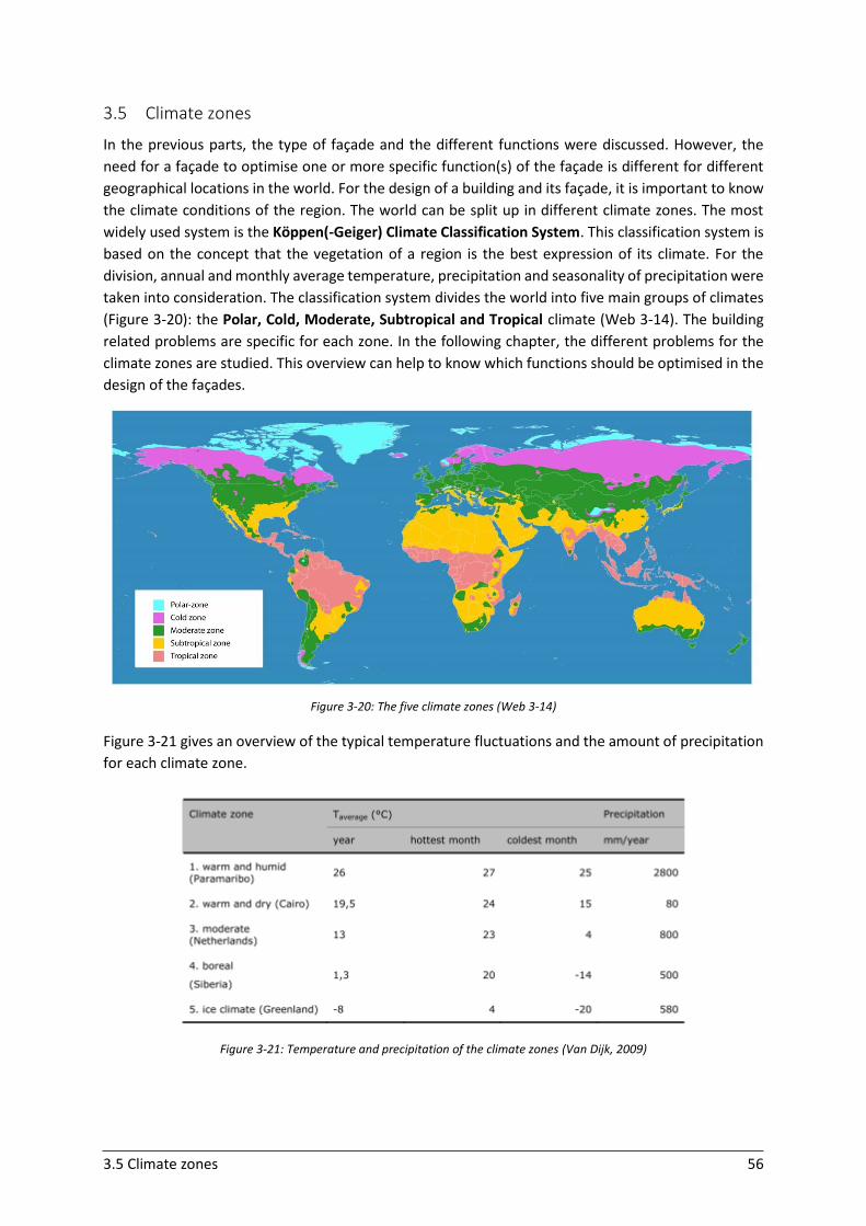
3.5 Climate zones 56
3.5 Climate zones
In the previous parts, the type of façade and the different functions were discussed. However, the
need for a façade to optimise one or more specific function(s) of the façade is different for different
geographical locations in the world. For the design of a building and its façade, it is important to know
the climate conditions of the region. The world can be split up in different climate zones. The most
widely used system is the Köppen(-Geiger) Climate Classification System. This classification system is
based on the concept that the vegetation of a region is the best expression of its climate. For the
division, annual and monthly average temperature, precipitation and seasonality of precipitation were
taken into consideration. The classification system divides the world into five main groups of climates
(Figure 3-20): the Polar, Cold, Moderate, Subtropical and Tropical climate (Web 3-14). The building
related problems are specific for each zone. In the following chapter, the different problems for the
climate zones are studied. This overview can help to know which functions should be optimised in the
design of the façades.
Figure 3-20: The five climate zones (Web 3-14)
Figure 3-21 gives an overview of the typical temperature fluctuations and the amount of precipitation
for each climate zone.
Figure 3-21: Temperature and precipitation of the climate zones (Van Dijk, 2009)
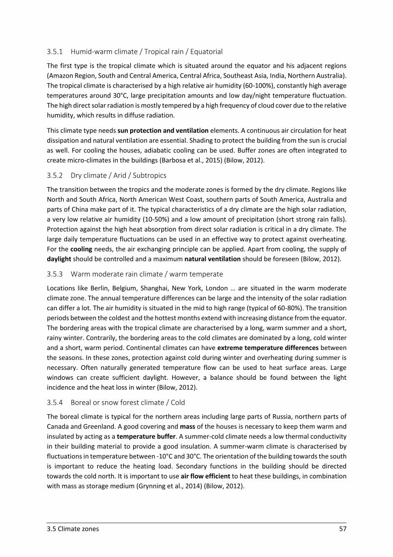
3.5 Climate zones 57
3.5.1 Humid-warm climate / Tropical rain / Equatorial
The first type is the tropical climate which is situated around the equator and his adjacent regions
(Amazon Region, South and Central America, Central Africa, Southeast Asia, India, Northern Australia).
The tropical climate is characterised by a high relative air humidity (60-100%), constantly high average
temperatures around 30°C, large precipitation amounts and low day/night temperature fluctuation.
The high direct solar radiation is mostly tempered by a high frequency of cloud cover due to the relative
humidity, which results in diffuse radiation.
This climate type needs sun protection and ventilation elements. A continuous air circulation for heat
dissipation and natural ventilation are essential. Shading to protect the building from the sun is crucial
as well. For cooling the houses, adiabatic cooling can be used. Buffer zones are often integrated to
create micro-climates in the buildings (Barbosa et al., 2015) (Bilow, 2012).
3.5.2 Dry climate / Arid / Subtropics
The transition between the tropics and the moderate zones is formed by the dry climate. Regions like
North and South Africa, North American West Coast, southern parts of South America, Australia and
parts of China make part of it. The typical characteristics of a dry climate are the high solar radiation,
a very low relative air humidity (10-50%) and a low amount of precipitation (short strong rain falls).
Protection against the high heat absorption from direct solar radiation is critical in a dry climate. The
large daily temperature fluctuations can be used in an effective way to protect against overheating.
For the cooling needs, the air exchanging principle can be applied. Apart from cooling, the supply of
daylight should be controlled and a maximum natural ventilation should be foreseen (Bilow, 2012).
3.5.3 Warm moderate rain climate / warm temperate
Locations like Berlin, Belgium, Shanghai, New York, London … are situated in the warm moderate
climate zone. The annual temperature differences can be large and the intensity of the solar radiation
can differ a lot. The air humidity is situated in the mid to high range (typical of 60-80%). The transition
periods between the coldest and the hottest months extend with increasing distance from the equator.
The bordering areas with the tropical climate are characterised by a long, warm summer and a short,
rainy winter. Contrarily, the bordering areas to the cold climates are dominated by a long, cold winter
and a short, warm period. Continental climates can have extreme temperature differences between
the seasons. In these zones, protection against cold during winter and overheating during summer is
necessary. Often naturally generated temperature flow can be used to heat surface areas. Large
windows can create sufficient daylight. However, a balance should be found between the light
incidence and the heat loss in winter (Bilow, 2012).
3.5.4 Boreal or snow forest climate / Cold
The boreal climate is typical for the northern areas including large parts of Russia, northern parts of
Canada and Greenland. A good covering and mass of the houses is necessary to keep them warm and
insulated by acting as a temperature buffer. A summer-cold climate needs a low thermal conductivity
in their building material to provide a good insulation. A summer-warm climate is characterised by
fluctuations in temperature between -10°C and 30°C. The orientation of the building towards the south
is important to reduce the heating load. Secondary functions in the building should be directed
towards the cold north. It is important to use air flow efficient to heat these buildings, in combination
with mass as storage medium (Grynning et al., 2014) (Bilow, 2012).
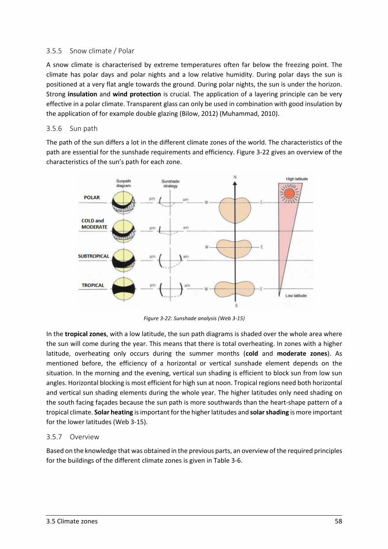
3.5 Climate zones 58
3.5.5 Snow climate / Polar
A snow climate is characterised by extreme temperatures often far below the freezing point. The
climate has polar days and polar nights and a low relative humidity. During polar days the sun is
positioned at a very flat angle towards the ground. During polar nights, the sun is under the horizon.
Strong insulation and wind protection is crucial. The application of a layering principle can be very
effective in a polar climate. Transparent glass can only be used in combination with good insulation by
the application of for example double glazing (Bilow, 2012) (Muhammad, 2010).
3.5.6 Sun path
The path of the sun differs a lot in the different climate zones of the world. The characteristics of the
path are essential for the sunshade requirements and efficiency. Figure 3-22 gives an overview of the
characteristics of the sun’s path for each zone.
Figure 3-22: Sunshade analysis (Web 3-15)
In the tropical zones, with a low latitude, the sun path diagrams is shaded over the whole area where
the sun will come during the year. This means that there is total overheating. In zones with a higher
latitude, overheating only occurs during the summer months (cold and moderate zones). As
mentioned before, the efficiency of a horizontal or vertical sunshade element depends on the
situation. In the morning and the evening, vertical sun shading is efficient to block sun from low sun
angles. Horizontal blocking is most efficient for high sun at noon. Tropical regions need both horizontal
and vertical sun shading elements during the whole year. The higher latitudes only need shading on
the south facing façades because the sun path is more southwards than the heart-shape pattern of a
tropical climate. Solar heating is important for the higher latitudes and solar shading is more important
for the lower latitudes (Web 3-15).
3.5.7 Overview
Based on the knowledge that was obtained in the previous parts, an overview of the required principles
for the buildings of the different climate zones is given in Table 3-6.
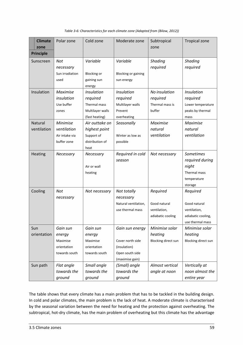
3.5 Climate zones 59
Table 3-6: Characteristics for each climate zone (Adapted from (Bilow, 2012))
Climate
zone
Polar zone Cold zone Moderate zone Subtropical
zone
Tropical zone
Principle
Sunscreen Not
necessary
Sun irradiation
used
Variable
Blocking or
gaining sun
energy
Variable
Blocking or gaining
sun energy
Shading
required
Shading
required
Insulation Maximise
insulation
Use buffer
zones
Insulation
required
Thermal mass
Multilayer walls
(fast heating)
Insulation
required
Multilayer walls
Prevent
overheating
No insulation
required
Thermal mass is
buffer
Insulation
required
Lower temperature
peaks by thermal
mass
Natural
ventilation
Minimise
ventilation
Air intake via
buffer zone
Air outtake on
highest point
Support of
distribution of
heat
Seasonally
Winter as low as
possible
Maximise
natural
ventilation
Maximise
natural
ventilation
Heating Necessary Necessary
Air or wall
heating
Required in cold
season
Not necessary Sometimes
required during
night
Thermal mass
temperature
storage
Cooling Not
necessary
Not necessary Not totally
necessary
Natural ventilation,
use thermal mass
Required
Good natural
ventilation,
adiabatic cooling
Required
Good natural
ventilation,
adiabatic cooling,
use thermal mass
Sun
orientation
Gain sun
energy
Maximise
orientation
towards south
Gain sun
energy
Maximise
orientation
towards south
Gain sun energy
Cover north side
(insulation)
Open south side
(maximise gain)
Minimise solar
heating
Blocking direct sun
Minimise solar
heating
Blocking direct sun
Sun path Flat angle
towards the
ground
Small angle
towards the
ground
(Small) angle
towards the
ground
Almost vertical
angle at noon
Vertically at
noon almost the
entire year
The table shows that every climate has a main problem that has to be tackled in the building design.
In cold and polar climates, the main problem is the lack of heat. A moderate climate is characterised
by the seasonal variation between the need for heating and the protection against overheating. The
subtropical, hot-dry climate, has the main problem of overheating but this climate has the advantage
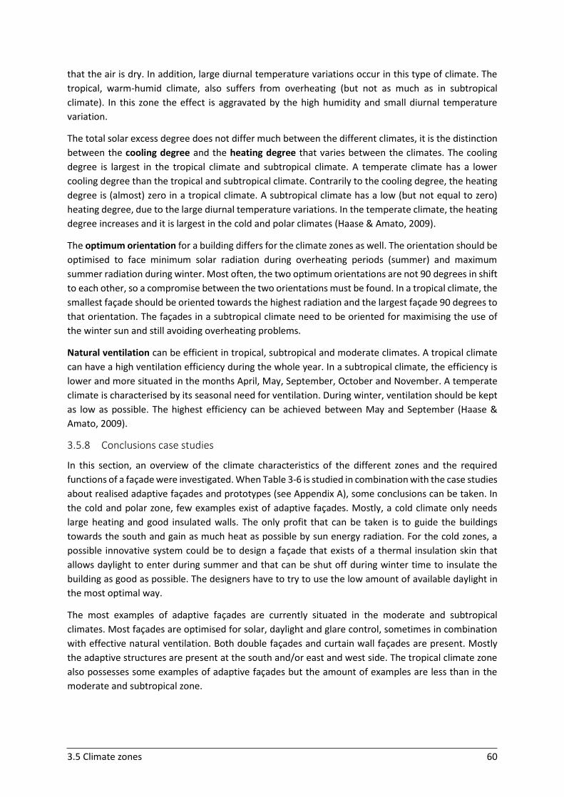
3.5 Climate zones 60
that the air is dry. In addition, large diurnal temperature variations occur in this type of climate. The
tropical, warm-humid climate, also suffers from overheating (but not as much as in subtropical
climate). In this zone the effect is aggravated by the high humidity and small diurnal temperature
variation.
The total solar excess degree does not differ much between the different climates, it is the distinction
between the cooling degree and the heating degree that varies between the climates. The cooling
degree is largest in the tropical climate and subtropical climate. A temperate climate has a lower
cooling degree than the tropical and subtropical climate. Contrarily to the cooling degree, the heating
degree is (almost) zero in a tropical climate. A subtropical climate has a low (but not equal to zero)
heating degree, due to the large diurnal temperature variations. In the temperate climate, the heating
degree increases and it is largest in the cold and polar climates (Haase & Amato, 2009).
The optimum orientation for a building differs for the climate zones as well. The orientation should be
optimised to face minimum solar radiation during overheating periods (summer) and maximum
summer radiation during winter. Most often, the two optimum orientations are not 90 degrees in shift
to each other, so a compromise between the two orientations must be found. In a tropical climate, the
smallest façade should be oriented towards the highest radiation and the largest façade 90 degrees to
that orientation. The façades in a subtropical climate need to be oriented for maximising the use of
the winter sun and still avoiding overheating problems.
Natural ventilation can be efficient in tropical, subtropical and moderate climates. A tropical climate
can have a high ventilation efficiency during the whole year. In a subtropical climate, the efficiency is
lower and more situated in the months April, May, September, October and November. A temperate
climate is characterised by its seasonal need for ventilation. During winter, ventilation should be kept
as low as possible. The highest efficiency can be achieved between May and September (Haase &
Amato, 2009).
3.5.8 Conclusions case studies
In this section, an overview of the climate characteristics of the different zones and the required
functions of a façade were investigated. When Table 3-6 is studied in combination with the case studies
about realised adaptive façades and prototypes (see Appendix A), some conclusions can be taken. In
the cold and polar zone, few examples exist of adaptive façades. Mostly, a cold climate only needs
large heating and good insulated walls. The only profit that can be taken is to guide the buildings
towards the south and gain as much heat as possible by sun energy radiation. For the cold zones, a
possible innovative system could be to design a façade that exists of a thermal insulation skin that
allows daylight to enter during summer and that can be shut off during winter time to insulate the
building as good as possible. The designers have to try to use the low amount of available daylight in
the most optimal way.
The most examples of adaptive façades are currently situated in the moderate and subtropical
climates. Most façades are optimised for solar, daylight and glare control, sometimes in combination
with effective natural ventilation. Both double façades and curtain wall façades are present. Mostly
the adaptive structures are present at the south and/or east and west side. The tropical climate zone
also possesses some examples of adaptive façades but the amount of examples are less than in the
moderate and subtropical zone.
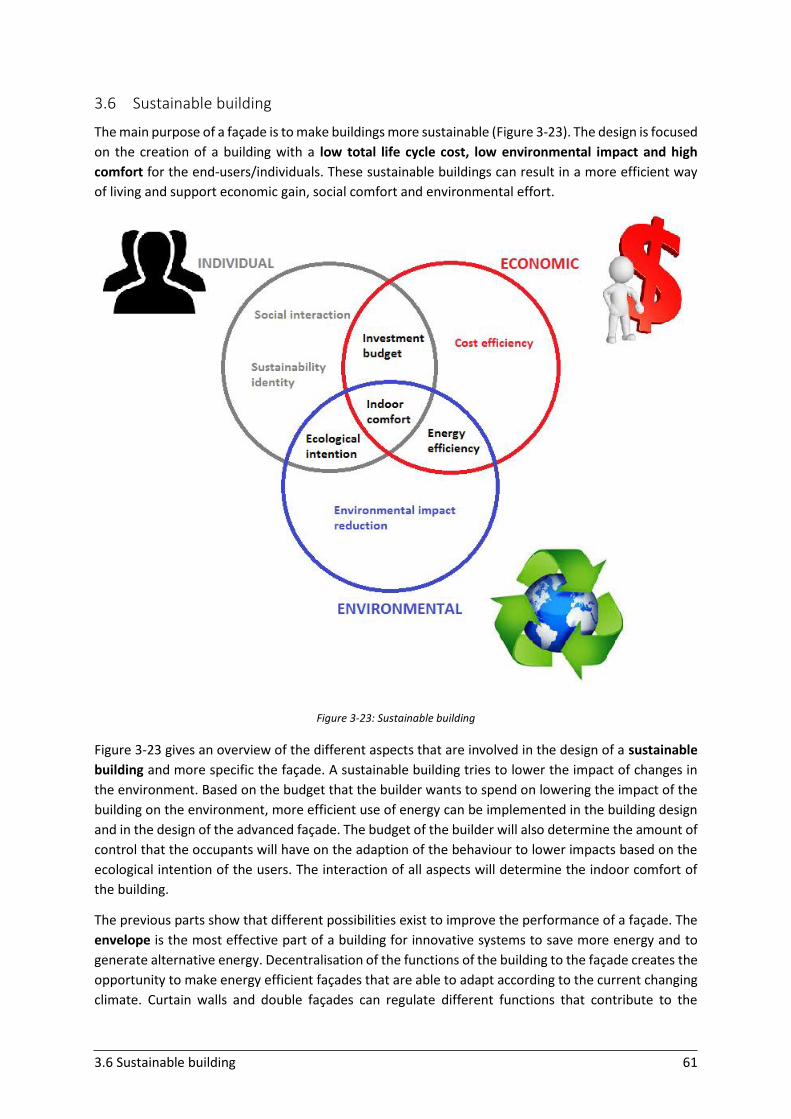
3.6 Sustainable building 61
3.6 Sustainable building
The main purpose of a façade is to make buildings more sustainable (Figure 3-23). The design is focused
on the creation of a building with a low total life cycle cost, low environmental impact and high
comfort for the end-users/individuals. These sustainable buildings can result in a more efficient way
of living and support economic gain, social comfort and environmental effort.
Figure 3-23: Sustainable building
Figure 3-23 gives an overview of the different aspects that are involved in the design of a sustainable
building and more specific the façade. A sustainable building tries to lower the impact of changes in
the environment. Based on the budget that the builder wants to spend on lowering the impact of the
building on the environment, more efficient use of energy can be implemented in the building design
and in the design of the advanced façade. The budget of the builder will also determine the amount of
control that the occupants will have on the adaption of the behaviour to lower impacts based on the
ecological intention of the users. The interaction of all aspects will determine the indoor comfort of
the building.
The previous parts show that different possibilities exist to improve the performance of a façade. The
envelope is the most effective part of a building for innovative systems to save more energy and to
generate alternative energy. Decentralisation of the functions of the building to the façade creates the
opportunity to make energy efficient façades that are able to adapt according to the current changing
climate. Curtain walls and double façades can regulate different functions that contribute to the
3.6 Sustainable building 62
performance of the building. Some functions are more easy to regulate than others. The climate
change and waste of material are worldwide problems to which structural adaptive façades can give
an efficient answer.
Advanced façades are accompanied automatically by an increased first cost for the clients. The
advantages of these façades need to convince the clients to invest this higher building cost compared
to conventional façades and to take the advantages of energy and productivity savings later. Integrated
façades result in lower life cycle costs because operating, maintenance and replacement costs are
reduced. The overall operating costs are linked to the annual energy cost which depends on the
demand for heating, cooling and lighting. Integrated façades are not suitable for people who want to
build as investment, because they want to build at the lowest possible cost.
To design an interactive façade, a team of experts needs to work together. The construction of a
functional, comfortable, energy efficient and aesthetical integrated façade requires a lot of expertise
and specific knowledge. Designing advanced façades includes knowledge about thermodynamics,
material sciences, air flow, lighting and daylighting, HVAC equipment … As a result architects, engineers
and natural sciences experts contribute to a multidisciplinary design culture. This team of different
experts need to make important design decisions. The decisions in the early phases have the biggest
impact on the project lifecycle and building performance (Kassem & Mitchell, 2015).
The design of a façade is often based on focusing on one functional parameter but forgets to take the
interactions between different functions into consideration. Mostly the design team focuses on the
thermal problem or daylight problem respectively. For façades, parameters like window dimensions,
construction material, insulation thickness, glazing type, building orientation ... all are of great
importance. These parameters are able to regulate different functions of the building. Therefore,
focusing on only one aspect is not efficient (Lee et al., 2002). Solar control can be efficiently combined
with the gain of solar energy by introducing building integrated photovoltaics in the façades. A future
area in building façades should focus on the creation of integrated façades that take more than only
one function into account to further increase the performance of the building (Klein, 2013).
Apart from the design of an interactive façade, the construction of a building is a complex process too.
The design evolves over time and often early design decisions are changed during the building process.
Different manufacturers are involved in the construction of the façade. This makes a good coordination
essential. The different applied systems need to work properly together, which is not always an easy
job (Lee et al., 2002).
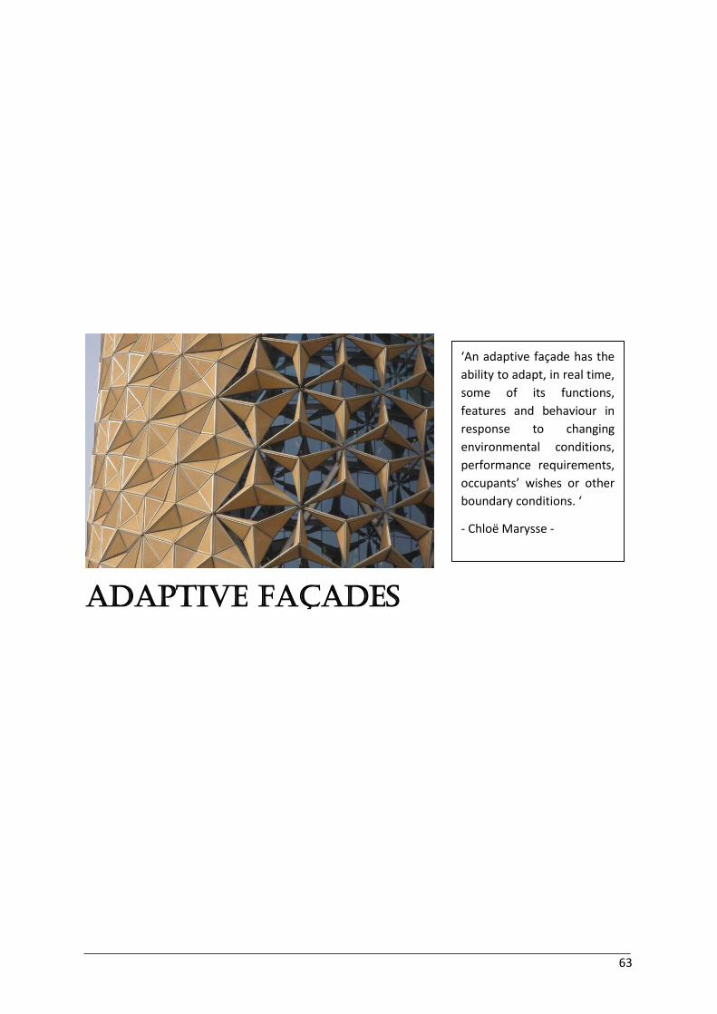
63
Adaptive Façades
‘An adaptive façade has the
ability to adapt, in real time,
some of its functions,
features and behaviour in
response to changing
environmental conditions,
performance requirements,
occupants’ wishes or other
boundary conditions. ‘
- Chloë Marysse -
4.1 Introduction 64
4 Adaptive façades 4.1 Introduction
During the last years, the popularity of low-energy buildings has increased enormously due to the
raising climate challenge. Buildings are responsible for a large part of the global energy consumption.
The building industry needs to focus more on sustainable designs to lower the negative climate impact.
Low-energy buildings can roughly be distinguished in two groups: active technology and passive design
strategies. Active technology is currently the most popular approach. Innovative technical devices that
enhance the efficiency of the conversion of resources or make use of renewable sources to supply
energy are the two basic types. In contrast, passive design strategies focus on the design of the building
and its construction to capture, store and distribute solar and wind energy (Loonen et al., 2013)
(Ibáñez-Puy et al., 2015). During the last years, researchers have already gained a lot of knowledge
about passive design strategies for buildings and further research is still going on. These efforts result
and will further result in a lot of promising future applications.
Traditional, static buildings make use of fixed systems that possess no flexibility, which results in
robust building designs. A robust design is typically oversized, with redundancy to deal with changing
properties. This redundancy is necessary to manage unexpected conditions and implies a large cost. In
addition, the buildings are typically equipped with a lot of HVAC systems that increase the cost of
energy consumption. In contrast, flexible, adaptive systems have the opportunity to maintain good
performance during their lifetime by anticipation and reaction in the façade without the need for
oversizing and redundancy (Loonen et al., 2013). The adaptive quality lowers the need for HVAC
systems and consequently the total energy cost of the building (Loonen, 2010).
Driven by the climate problem, adaption came to the front in the design of buildings. Adaptive
structures - and adaptive architecture in general in terms of buildings - refer to continuously changing
the configuration of buildings to perform better. Adaptive buildings are more efficient by the clever
use of light and space. Due to the changed approach in the design of buildings, the façade is no longer
seen as just a static barrier separating the interior building environment from the external one. The
façades possess the ability to adapt to climate changes. To design a façade that responds to changing
climate conditions, multiple objectives are important, such as the building environment and the
objectives of the building occupants. The interaction between these multiple perspectives makes a
good design a complex affair (Kirkegaard, 2011) (Loonen, 2010). It is self-evident that the adaptive
systems need to be optimised for the specific type of climate in which they will be used. Next to the
type of climate, the season and the daytime or night-time play an essential role for the façade (López
et al., 2015).
In this chapter, the characteristics of adaptive façades and their specific type of movement and control
will be examined in detail in order to come to a global classification system. This will allow to give a
structured overview of which applications already exist and which domains need further examination
and development. The classification is also useful to combine with the findings about the adaptive
needs of the different climates to design promising applications.
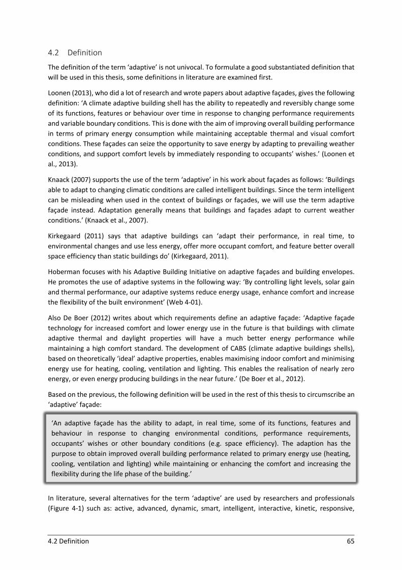
4.2 Definition 65
‘An adaptive façade has the ability to adapt, in real time, some of its functions, features and
behaviour in response to changing environmental conditions, performance requirements,
occupants’ wishes or other boundary conditions (e.g. space efficiency). The adaption has the
purpose to obtain improved overall building performance related to primary energy use (heating,
cooling, ventilation and lighting) while maintaining or enhancing the comfort and increasing the
flexibility during the life phase of the building.’
4.2 Definition
The definition of the term ‘adaptive’ is not univocal. To formulate a good substantiated definition that
will be used in this thesis, some definitions in literature are examined first.
Loonen (2013), who did a lot of research and wrote papers about adaptive façades, gives the following
definition: ‘A climate adaptive building shell has the ability to repeatedly and reversibly change some
of its functions, features or behaviour over time in response to changing performance requirements
and variable boundary conditions. This is done with the aim of improving overall building performance
in terms of primary energy consumption while maintaining acceptable thermal and visual comfort
conditions. These façades can seize the opportunity to save energy by adapting to prevailing weather
conditions, and support comfort levels by immediately responding to occupants’ wishes.’ (Loonen et
al., 2013).
Knaack (2007) supports the use of the term ‘adaptive’ in his work about façades as follows: ‘Buildings
able to adapt to changing climatic conditions are called intelligent buildings. Since the term intelligent
can be misleading when used in the context of buildings or façades, we will use the term adaptive
façade instead. Adaptation generally means that buildings and façades adapt to current weather
conditions.’ (Knaack et al., 2007).
Kirkegaard (2011) says that adaptive buildings can ‘adapt their performance, in real time, to
environmental changes and use less energy, offer more occupant comfort, and feature better overall
space efficiency than static buildings do’ (Kirkegaard, 2011).
Hoberman focuses with his Adaptive Building Initiative on adaptive façades and building envelopes.
He promotes the use of adaptive systems in the following way: ‘By controlling light levels, solar gain
and thermal performance, our adaptive systems reduce energy usage, enhance comfort and increase
the flexibility of the built environment’ (Web 4-01).
Also De Boer (2012) writes about which requirements define an adaptive façade: ‘Adaptive façade
technology for increased comfort and lower energy use in the future is that buildings with climate
adaptive thermal and daylight properties will have a much better energy performance while
maintaining a high comfort standard. The development of CABS (climate adaptive buildings shells),
based on theoretically ‘ideal’ adaptive properties, enables maximising indoor comfort and minimising
energy use for heating, cooling, ventilation and lighting. This enables the realisation of nearly zero
energy, or even energy producing buildings in the near future.’ (De Boer et al., 2012).
Based on the previous, the following definition will be used in the rest of this thesis to circumscribe an
‘adaptive’ façade:
In literature, several alternatives for the term ‘adaptive’ are used by researchers and professionals
(Figure 4-1) such as: active, advanced, dynamic, smart, intelligent, interactive, kinetic, responsive,
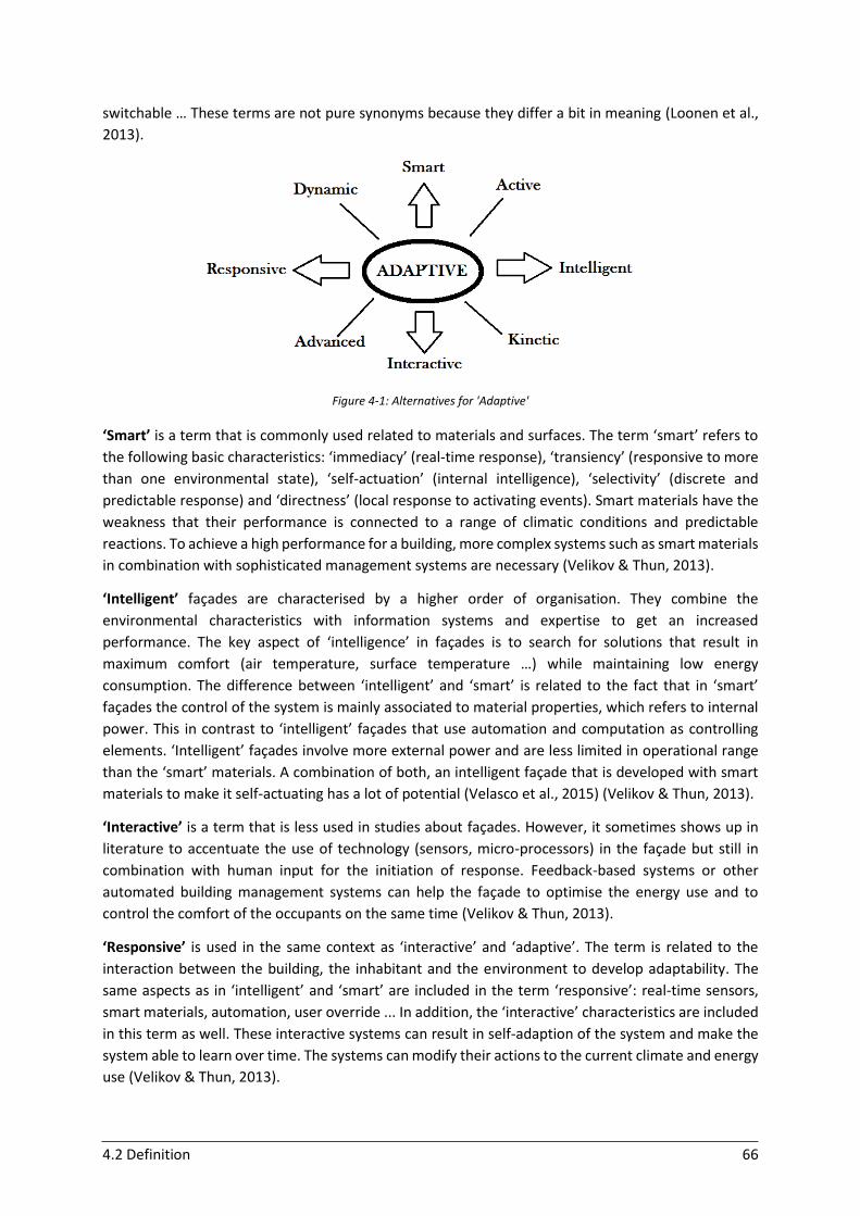
4.2 Definition 66
switchable … These terms are not pure synonyms because they differ a bit in meaning (Loonen et al.,
2013).
Figure 4-1: Alternatives for 'Adaptive'
‘Smart’ is a term that is commonly used related to materials and surfaces. The term ‘smart’ refers to
the following basic characteristics: ‘immediacy’ (real-time response), ‘transiency’ (responsive to more
than one environmental state), ‘self-actuation’ (internal intelligence), ‘selectivity’ (discrete and
predictable response) and ‘directness’ (local response to activating events). Smart materials have the
weakness that their performance is connected to a range of climatic conditions and predictable
reactions. To achieve a high performance for a building, more complex systems such as smart materials
in combination with sophisticated management systems are necessary (Velikov & Thun, 2013).
‘Intelligent’ façades are characterised by a higher order of organisation. They combine the
environmental characteristics with information systems and expertise to get an increased
performance. The key aspect of ‘intelligence’ in façades is to search for solutions that result in
maximum comfort (air temperature, surface temperature …) while maintaining low energy
consumption. The difference between ‘intelligent’ and ‘smart’ is related to the fact that in ‘smart’
façades the control of the system is mainly associated to material properties, which refers to internal
power. This in contrast to ‘intelligent’ façades that use automation and computation as controlling
elements. ‘Intelligent’ façades involve more external power and are less limited in operational range
than the ‘smart’ materials. A combination of both, an intelligent façade that is developed with smart
materials to make it self-actuating has a lot of potential (Velasco et al., 2015) (Velikov & Thun, 2013).
‘Interactive’ is a term that is less used in studies about façades. However, it sometimes shows up in
literature to accentuate the use of technology (sensors, micro-processors) in the façade but still in
combination with human input for the initiation of response. Feedback-based systems or other
automated building management systems can help the façade to optimise the energy use and to
control the comfort of the occupants on the same time (Velikov & Thun, 2013).
‘Responsive’ is used in the same context as ‘interactive’ and ‘adaptive’. The term is related to the
interaction between the building, the inhabitant and the environment to develop adaptability. The
same aspects as in ‘intelligent’ and ‘smart’ are included in the term ‘responsive’: real-time sensors,
smart materials, automation, user override ... In addition, the ‘interactive’ characteristics are included
in this term as well. These interactive systems can result in self-adaption of the system and make the
system able to learn over time. The systems can modify their actions to the current climate and energy
use (Velikov & Thun, 2013).
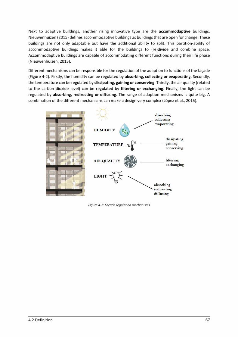
4.2 Definition 67
Next to adaptive buildings, another rising innovative type are the accommodaptive buildings.
Nieuwenhuizen (2015) defines accommodaptive buildings as buildings that are open for change. These
buildings are not only adaptable but have the additional ability to split. This partition-ability of
accommodaptive buildings makes it able for the buildings to (re)divide and combine space.
Accommodaptive buildings are capable of accommodating different functions during their life phase
(Nieuwenhuizen, 2015).
Different mechanisms can be responsible for the regulation of the adaption to functions of the façade
(Figure 4-2). Firstly, the humidity can be regulated by absorbing, collecting or evaporating. Secondly,
the temperature can be regulated by dissipating, gaining or conserving. Thirdly, the air quality (related
to the carbon dioxide level) can be regulated by filtering or exchanging. Finally, the light can be
regulated by absorbing, redirecting or diffusing. The range of adaption mechanisms is quite big. A
combination of the different mechanisms can make a design very complex (López et al., 2015).
Figure 4-2: Façade regulation mechanisms
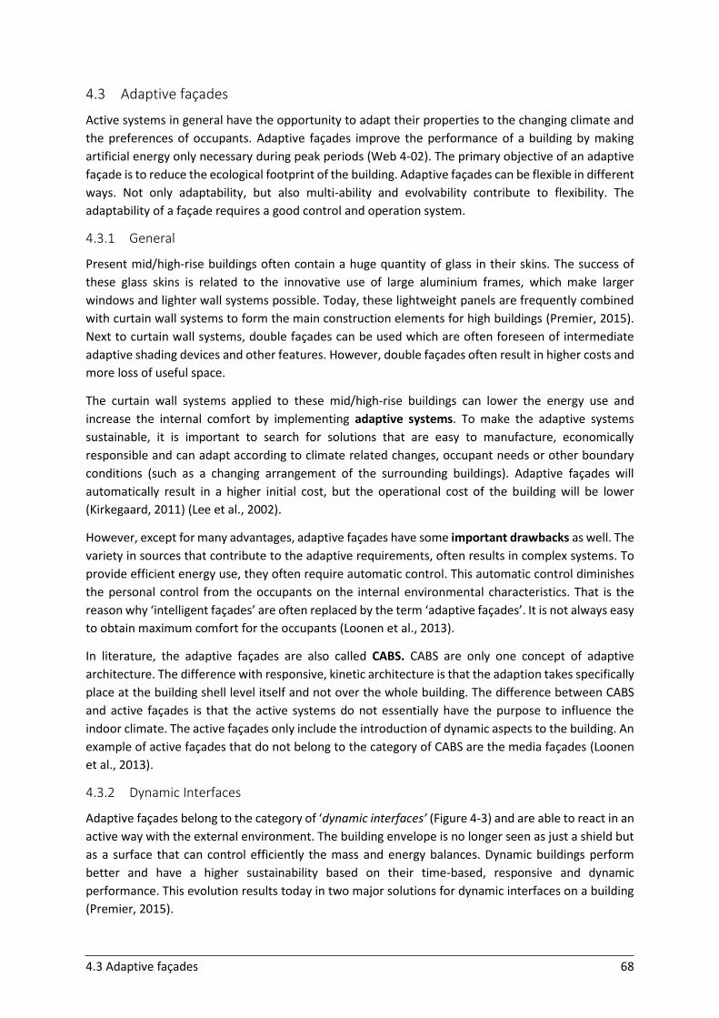
4.3 Adaptive façades 68
4.3 Adaptive façades
Active systems in general have the opportunity to adapt their properties to the changing climate and
the preferences of occupants. Adaptive façades improve the performance of a building by making
artificial energy only necessary during peak periods (Web 4-02). The primary objective of an adaptive
façade is to reduce the ecological footprint of the building. Adaptive façades can be flexible in different
ways. Not only adaptability, but also multi-ability and evolvability contribute to flexibility. The
adaptability of a façade requires a good control and operation system.
4.3.1 General
Present mid/high-rise buildings often contain a huge quantity of glass in their skins. The success of
these glass skins is related to the innovative use of large aluminium frames, which make larger
windows and lighter wall systems possible. Today, these lightweight panels are frequently combined
with curtain wall systems to form the main construction elements for high buildings (Premier, 2015).
Next to curtain wall systems, double façades can be used which are often foreseen of intermediate
adaptive shading devices and other features. However, double façades often result in higher costs and
more loss of useful space.
The curtain wall systems applied to these mid/high-rise buildings can lower the energy use and
increase the internal comfort by implementing adaptive systems. To make the adaptive systems
sustainable, it is important to search for solutions that are easy to manufacture, economically
responsible and can adapt according to climate related changes, occupant needs or other boundary
conditions (such as a changing arrangement of the surrounding buildings). Adaptive façades will
automatically result in a higher initial cost, but the operational cost of the building will be lower
(Kirkegaard, 2011) (Lee et al., 2002).
However, except for many advantages, adaptive façades have some important drawbacks as well. The
variety in sources that contribute to the adaptive requirements, often results in complex systems. To
provide efficient energy use, they often require automatic control. This automatic control diminishes
the personal control from the occupants on the internal environmental characteristics. That is the
reason why ‘intelligent façades’ are often replaced by the term ‘adaptive façades’. It is not always easy
to obtain maximum comfort for the occupants (Loonen et al., 2013).
In literature, the adaptive façades are also called CABS. CABS are only one concept of adaptive
architecture. The difference with responsive, kinetic architecture is that the adaption takes specifically
place at the building shell level itself and not over the whole building. The difference between CABS
and active façades is that the active systems do not essentially have the purpose to influence the
indoor climate. The active façades only include the introduction of dynamic aspects to the building. An
example of active façades that do not belong to the category of CABS are the media façades (Loonen
et al., 2013).
4.3.2 Dynamic Interfaces
Adaptive façades belong to the category of ‘dynamic interfaces’ (Figure 4-3) and are able to react in an
active way with the external environment. The building envelope is no longer seen as just a shield but
as a surface that can control efficiently the mass and energy balances. Dynamic buildings perform
better and have a higher sustainability based on their time-based, responsive and dynamic
performance. This evolution results today in two major solutions for dynamic interfaces on a building
(Premier, 2015).
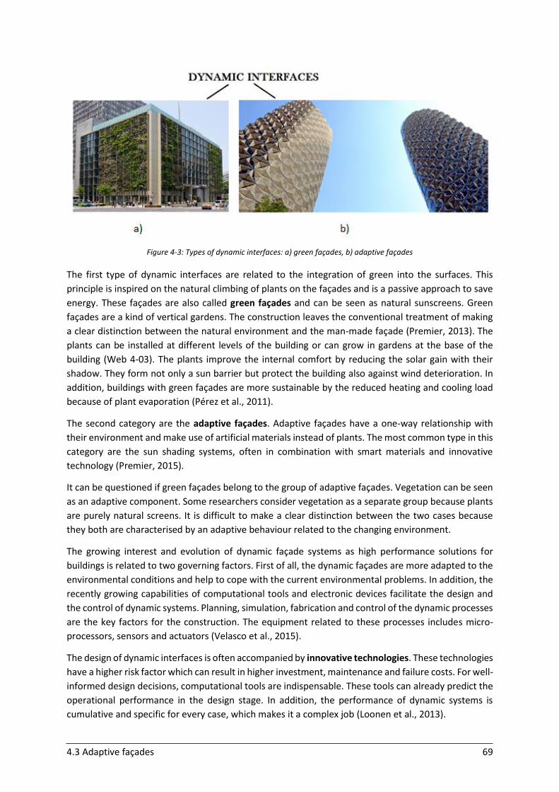
4.3 Adaptive façades 69
Figure 4-3: Types of dynamic interfaces: a) green façades, b) adaptive façades
The first type of dynamic interfaces are related to the integration of green into the surfaces. This
principle is inspired on the natural climbing of plants on the façades and is a passive approach to save
energy. These façades are also called green façades and can be seen as natural sunscreens. Green
façades are a kind of vertical gardens. The construction leaves the conventional treatment of making
a clear distinction between the natural environment and the man-made façade (Premier, 2013). The
plants can be installed at different levels of the building or can grow in gardens at the base of the
building (Web 4-03). The plants improve the internal comfort by reducing the solar gain with their
shadow. They form not only a sun barrier but protect the building also against wind deterioration. In
addition, buildings with green façades are more sustainable by the reduced heating and cooling load
because of plant evaporation (Pérez et al., 2011).
The second category are the adaptive façades. Adaptive façades have a one-way relationship with
their environment and make use of artificial materials instead of plants. The most common type in this
category are the sun shading systems, often in combination with smart materials and innovative
technology (Premier, 2015).
It can be questioned if green façades belong to the group of adaptive façades. Vegetation can be seen
as an adaptive component. Some researchers consider vegetation as a separate group because plants
are purely natural screens. It is difficult to make a clear distinction between the two cases because
they both are characterised by an adaptive behaviour related to the changing environment.
The growing interest and evolution of dynamic façade systems as high performance solutions for
buildings is related to two governing factors. First of all, the dynamic façades are more adapted to the
environmental conditions and help to cope with the current environmental problems. In addition, the
recently growing capabilities of computational tools and electronic devices facilitate the design and
the control of dynamic systems. Planning, simulation, fabrication and control of the dynamic processes
are the key factors for the construction. The equipment related to these processes includes micro-
processors, sensors and actuators (Velasco et al., 2015).
The design of dynamic interfaces is often accompanied by innovative technologies. These technologies
have a higher risk factor which can result in higher investment, maintenance and failure costs. For well-
informed design decisions, computational tools are indispensable. These tools can already predict the
operational performance in the design stage. In addition, the performance of dynamic systems is
cumulative and specific for every case, which makes it a complex job (Loonen et al., 2013).
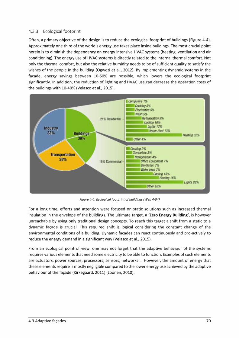
4.3 Adaptive façades 70
4.3.3 Ecological footprint
Often, a primary objective of the design is to reduce the ecological footprint of buildings (Figure 4-4).
Approximately one third of the world’s energy use takes place inside buildings. The most crucial point
herein is to diminish the dependency on energy intensive HVAC systems (heating, ventilation and air
conditioning). The energy use of HVAC systems is directly related to the internal thermal comfort. Not
only the thermal comfort, but also the relative humidity needs to be of sufficient quality to satisfy the
wishes of the people in the building (Ogwezi et al., 2012). By implementing dynamic systems in the
façade, energy savings between 10-50% are possible, which lowers the ecological footprint
significantly. In addition, the reduction of lighting and HVAC use can decrease the operation costs of
the buildings with 10-40% (Velasco et al., 2015).
Figure 4-4: Ecological footprint of buildings (Web 4-04)
For a long time, efforts and attention were focused on static solutions such as increased thermal
insulation in the envelope of the buildings. The ultimate target, a ‘Zero Energy Building’, is however
unreachable by using only traditional design concepts. To reach this target a shift from a static to a
dynamic façade is crucial. This required shift is logical considering the constant change of the
environmental conditions of a building. Dynamic façades can react continuously and pro-actively to
reduce the energy demand in a significant way (Velasco et al., 2015).
From an ecological point of view, one may not forget that the adaptive behaviour of the systems
requires various elements that need some electricity to be able to function. Examples of such elements
are actuators, power sources, processors, sensors, networks … However, the amount of energy that
these elements require is mostly negligible compared to the lower energy use achieved by the adaptive
behaviour of the façade (Kirkegaard, 2011) (Loonen, 2010).
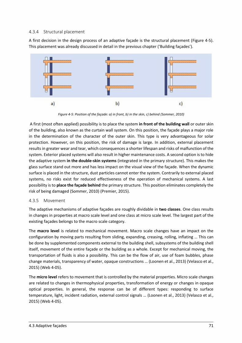
4.3 Adaptive façades 71
4.3.4 Structural placement
A first decision in the design process of an adaptive façade is the structural placement (Figure 4-5).
This placement was already discussed in detail in the previous chapter (‘Building façades’).
Figure 4-5: Position of the façade: a) in front, b) in the skin, c) behind (Sommer, 2010)
A first (most often applied) possibility is to place the system in front of the building wall or outer skin
of the building, also known as the curtain wall system. On this position, the façade plays a major role
in the determination of the character of the outer skin. This type is very advantageous for solar
protection. However, on this position, the risk of damage is large. In addition, external placement
results in greater wear and tear, which consequences a shorter lifespan and risks of malfunction of the
system. Exterior placed systems will also result in higher maintenance costs. A second option is to hide
the adaptive system in the double-skin systems (integrated in the primary structure). This makes the
glass surface stand out more and has less impact on the visual view of the façade. When the dynamic
surface is placed in the structure, dust particles cannot enter the system. Contrarily to external placed
systems, no risks exist for reduced effectiveness of the operation of mechanical systems. A last
possibility is to place the façade behind the primary structure. This position eliminates completely the
risk of being damaged (Sommer, 2010) (Premier, 2015).
4.3.5 Movement
The adaptive mechanisms of adaptive façades are roughly dividable in two classes. One class results
in changes in properties at macro scale level and one class at micro scale level. The largest part of the
existing façades belongs to the macro scale category.
The macro level is related to mechanical movement. Macro scale changes have an impact on the
configuration by moving parts resulting from sliding, expanding, creasing, rolling, inflating … This can
be done by supplemented components external to the building shell, subsystems of the building shell
itself, movement of the entire façade or the building as a whole. Except for mechanical moving, the
transportation of fluids is also a possibility. This can be the flow of air, use of foam bubbles, phase
change materials, transparency of water, opaque constructions … (Loonen et al., 2013) (Velasco et al.,
2015) (Web 4-05).
The micro level refers to movement that is controlled by the material properties. Micro scale changes
are related to changes in thermophysical properties, transformation of energy or changes in opaque
optical properties. In general, the response can be of different types: responding to surface
temperature, light, incident radiation, external control signals … (Loonen et al., 2013) (Velasco et al.,
2015) (Web 4-05).
4.3 Adaptive façades 72
4.3.6 Flexible systems: adaptability, multi-ability and evolvability
Adaptive façades emphasise flexibility during the life phase of the building. A building with an
intelligent façade makes optimal use of the energy from the external environment. This lowers the
amount of artificial energy that is necessary for achieving comfortable internal conditions (Ibáñez-Puy
et al., 2015).
The flexibility in adaptive façades can be subdivided in three different aspects: adaptability, multi-
ability and evolvability. The building industry has a lack of focus on adaptive aspects which results in a
lot of energy waste, which is not suitable considering the changing climate (Hoberman & Schwitter,
2008).
Adaptability is defined by Ferguson (2007) as ‘the ability of a system to deliver intended functionality
considering multiple criteria under variable conditions through the design variables changing their
physical values over time’. The façade acts as climate mediator between comfort needs and what is
available in the environment.
Multi-ability is referring to non-simultaneous performance requirements. This means that the façades
are able to play different roles over time. In contrast to the term ‘adaptability’, multi-ability refers to
the fulfilling of multiple objectives consecutively instead of concurrently. Multi-ability implies also that
the functions to which the adaptive façade is optimised, can have a spatial variability to obtain the
most efficient solutions. The spatial variation of the building’s properties makes that different parts
are working independently (Loonen et al., 2013).
Evolvability, sometimes also called survivability, is more related to the long-term capacities of the
façade. The evolvability refers to the capacity of the façade to react to changes in the future. These
changes can come from both the outside or the inside (changing urban environment, functional
changes of the building …). It is important that the façade has the opportunity to continue operation
as intended. The building may not suffer remarkably from impacts of changes in the future (Loonen et
al., 2013).
4.3.7 Environmental impacts during the building’s lifetime
The changes in the environment can be of different orders of time. First of all, the building’s envelope
is influenced by short-term fluctuations which change in order of seconds. These are mostly stochastic
processes. An example are the wind speed and wind direction. Next, changing conditions in the order
of minutes are possible, such as cloud cover and daylight availability. Most climate adaptive façade
systems are designed to lower the impact of these changes. They play with the degree of transparency
to increase the comfort. Furthermore, the angular movement of the sun through the sky results in
fluctuations in the air temperature. The resulting changes are in the order of magnitude of hours.
Furthermore, diurnal changes are present as a consequence of the occupants’ behaviour in the
building and meteorological boundary conditions. The availability of solar radiation can be efficiently
adapted by using thermal storage principles. The last group of changes are the seasonal changes during
winter, summer, spring and autumn. The different seasons have different boundary conditions, such
as the altitude of the sun (Loonen et al., 2013). Figure 4-6 gives an example of the interaction of
functions and the environmental changes in different orders of time. The example is based on the
behaviour of a west façade.
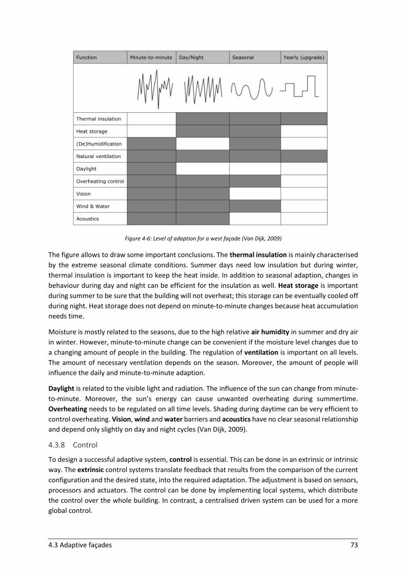
4.3 Adaptive façades 73
Figure 4-6: Level of adaption for a west façade (Van Dijk, 2009)
The figure allows to draw some important conclusions. The thermal insulation is mainly characterised
by the extreme seasonal climate conditions. Summer days need low insulation but during winter,
thermal insulation is important to keep the heat inside. In addition to seasonal adaption, changes in
behaviour during day and night can be efficient for the insulation as well. Heat storage is important
during summer to be sure that the building will not overheat; this storage can be eventually cooled off
during night. Heat storage does not depend on minute-to-minute changes because heat accumulation
needs time.
Moisture is mostly related to the seasons, due to the high relative air humidity in summer and dry air
in winter. However, minute-to-minute change can be convenient if the moisture level changes due to
a changing amount of people in the building. The regulation of ventilation is important on all levels.
The amount of necessary ventilation depends on the season. Moreover, the amount of people will
influence the daily and minute-to-minute adaption.
Daylight is related to the visible light and radiation. The influence of the sun can change from minute-
to-minute. Moreover, the sun’s energy can cause unwanted overheating during summertime.
Overheating needs to be regulated on all time levels. Shading during daytime can be very efficient to
control overheating. Vision, wind and water barriers and acoustics have no clear seasonal relationship
and depend only slightly on day and night cycles (Van Dijk, 2009).
4.3.8 Control
To design a successful adaptive system, control is essential. This can be done in an extrinsic or intrinsic
way. The extrinsic control systems translate feedback that results from the comparison of the current
configuration and the desired state, into the required adaptation. The adjustment is based on sensors,
processors and actuators. The control can be done by implementing local systems, which distribute
the control over the whole building. In contrast, a centralised driven system can be used for a more
global control.
4.3 Adaptive façades 74
Intrinsic systems do not make use of external decision making components, but are based on direct
control by transforming environmental impacts. These environmental inputs, such as temperature,
wind speed, solar radiation ... trigger the automatic adaption of the façade. In intrinsic systems, both
actuators and sensors are combined in one step. Intrinsic systems have advantages and disadvantages
compared to extrinsic systems. They do not need electricity or fuel to make the transition possible. In
addition, their number of components is limited. The main disadvantage is that the tuning of the
properties and variables of the system is done on a range of expected conditions. If the variations go
further than expected, the system will not be able to adapt in response to the unexpected conditions.
As previously mentioned, most CABS belong to the macro scale category. These systems are mainly
driven by extrinsic control types. The CABS that belong to the micro scale category are combined with
an intrinsic or extrinsic control type, depending on the situation. To work really efficiently, automated
systems that provide conditions of the average person need to be combined with options to meet
personal preferences. However, it is difficult to integrate these systems in the building’s envelope. To
facilitate the working principle, it is possible to constrain the rate of change to certain boundaries
(Loonen et al., 2013).
4.3.9 Operation
Not only the design of CABS is very complex, the operation phase is complicated as well. The multiple,
adaptive, independent performance requirements are often competitive and conflicting. However, the
various systems have to work together. A lot of trade-off options have to be solved, such as daylight
vs. glare, views vs. privacy, fresh air vs. draught risk, solar shading vs. artificial lighting … For adaptive
façades, strategies that evaluate several alternatives are necessary. For this, model based predictive
control strategies supplied with weather forecasts are useful. A good cooperation between the control
of the adaptive system and other building services is critical (Loonen et al., 2013).
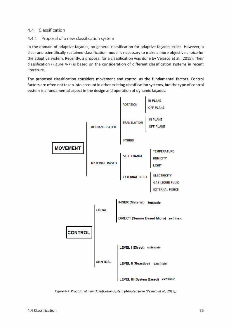
4.4 Classification 75
4.4 Classification
4.4.1 Proposal of a new classification system
In the domain of adaptive façades, no general classification for adaptive façades exists. However, a
clear and scientifically sustained classification model is necessary to make a more objective choice for
the adaptive system. Recently, a proposal for a classification was done by Velasco et al. (2015). Their
classification (Figure 4-7) is based on the consideration of different classification systems in recent
literature.
The proposed classification considers movement and control as the fundamental factors. Control
factors are often not taken into account in other existing classification systems, but the type of control
system is a fundamental aspect in the design and operation of dynamic façades.
Figure 4-7: Proposal of new classification system (Adapted from (Velasco et al., 2015))
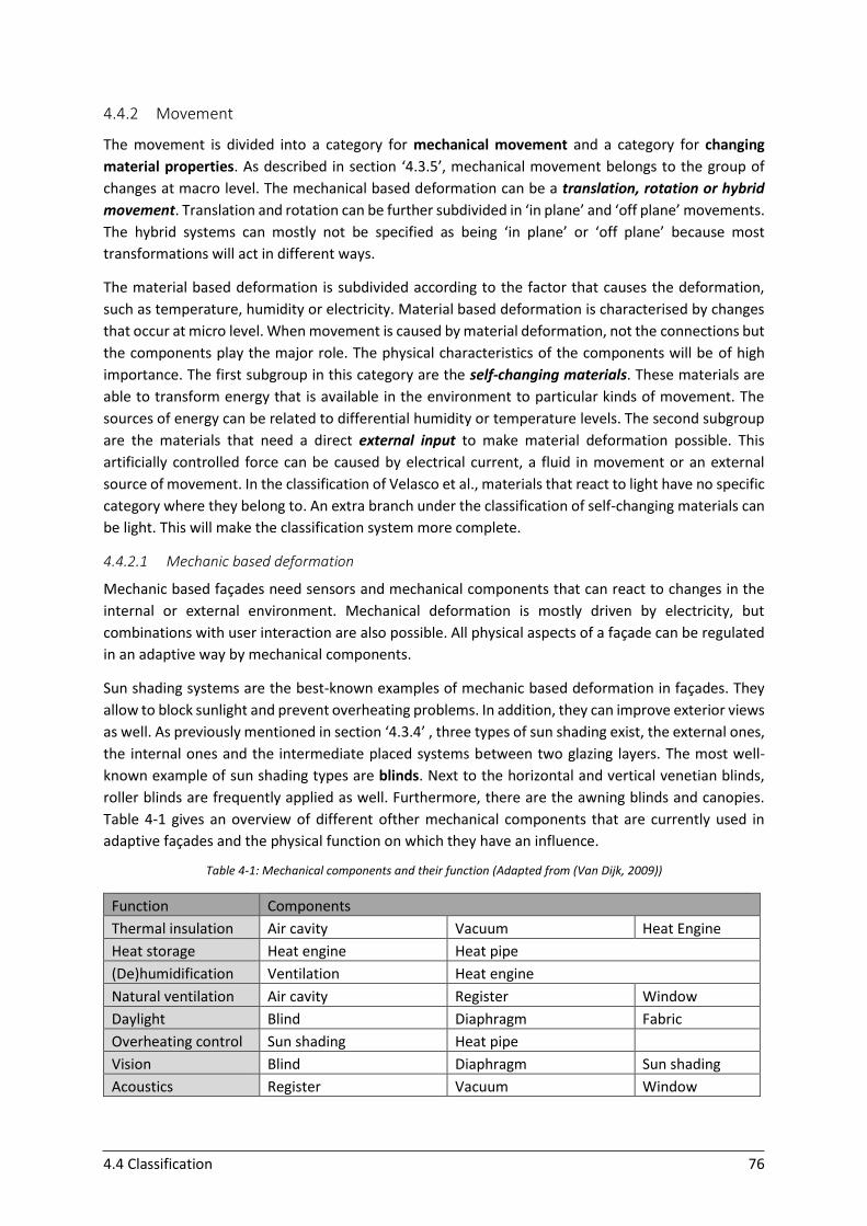
4.4 Classification 76
4.4.2 Movement
The movement is divided into a category for mechanical movement and a category for changing
material properties. As described in section ‘4.3.5’, mechanical movement belongs to the group of
changes at macro level. The mechanical based deformation can be a translation, rotation or hybrid
movement. Translation and rotation can be further subdivided in ‘in plane’ and ‘off plane’ movements.
The hybrid systems can mostly not be specified as being ‘in plane’ or ‘off plane’ because most
transformations will act in different ways.
The material based deformation is subdivided according to the factor that causes the deformation,
such as temperature, humidity or electricity. Material based deformation is characterised by changes
that occur at micro level. When movement is caused by material deformation, not the connections but
the components play the major role. The physical characteristics of the components will be of high
importance. The first subgroup in this category are the self-changing materials. These materials are
able to transform energy that is available in the environment to particular kinds of movement. The
sources of energy can be related to differential humidity or temperature levels. The second subgroup
are the materials that need a direct external input to make material deformation possible. This
artificially controlled force can be caused by electrical current, a fluid in movement or an external
source of movement. In the classification of Velasco et al., materials that react to light have no specific
category where they belong to. An extra branch under the classification of self-changing materials can
be light. This will make the classification system more complete.
4.4.2.1 Mechanic based deformation
Mechanic based façades need sensors and mechanical components that can react to changes in the
internal or external environment. Mechanical deformation is mostly driven by electricity, but
combinations with user interaction are also possible. All physical aspects of a façade can be regulated
in an adaptive way by mechanical components.
Sun shading systems are the best-known examples of mechanic based deformation in façades. They
allow to block sunlight and prevent overheating problems. In addition, they can improve exterior views
as well. As previously mentioned in section ‘4.3.4’ , three types of sun shading exist, the external ones,
the internal ones and the intermediate placed systems between two glazing layers. The most well-
known example of sun shading types are blinds. Next to the horizontal and vertical venetian blinds,
roller blinds are frequently applied as well. Furthermore, there are the awning blinds and canopies.
Table 4-1 gives an overview of different ofther mechanical components that are currently used in
adaptive façades and the physical function on which they have an influence.
Table 4-1: Mechanical components and their function (Adapted from (Van Dijk, 2009))
Function Components
Thermal insulation Air cavity Vacuum Heat Engine
Heat storage Heat engine Heat pipe
(De)humidification Ventilation Heat engine
Natural ventilation Air cavity Register Window
Daylight Blind Diaphragm Fabric
Overheating control Sun shading Heat pipe
Vision Blind Diaphragm Sun shading
Acoustics Register Vacuum Window
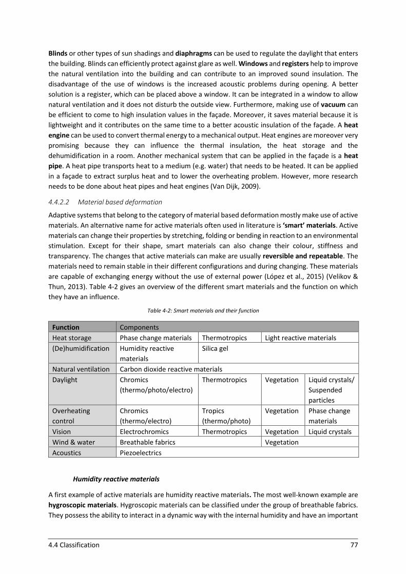
4.4 Classification 77
Blinds or other types of sun shadings and diaphragms can be used to regulate the daylight that enters
the building. Blinds can efficiently protect against glare as well. Windows and registers help to improve
the natural ventilation into the building and can contribute to an improved sound insulation. The
disadvantage of the use of windows is the increased acoustic problems during opening. A better
solution is a register, which can be placed above a window. It can be integrated in a window to allow
natural ventilation and it does not disturb the outside view. Furthermore, making use of vacuum can
be efficient to come to high insulation values in the façade. Moreover, it saves material because it is
lightweight and it contributes on the same time to a better acoustic insulation of the façade. A heat
engine can be used to convert thermal energy to a mechanical output. Heat engines are moreover very
promising because they can influence the thermal insulation, the heat storage and the
dehumidification in a room. Another mechanical system that can be applied in the façade is a heat
pipe. A heat pipe transports heat to a medium (e.g. water) that needs to be heated. It can be applied
in a façade to extract surplus heat and to lower the overheating problem. However, more research
needs to be done about heat pipes and heat engines (Van Dijk, 2009).
4.4.2.2 Material based deformation
Adaptive systems that belong to the category of material based deformation mostly make use of active
materials. An alternative name for active materials often used in literature is ‘smart’ materials. Active
materials can change their properties by stretching, folding or bending in reaction to an environmental
stimulation. Except for their shape, smart materials can also change their colour, stiffness and
transparency. The changes that active materials can make are usually reversible and repeatable. The
materials need to remain stable in their different configurations and during changing. These materials
are capable of exchanging energy without the use of external power (López et al., 2015) (Velikov &
Thun, 2013). Table 4-2 gives an overview of the different smart materials and the function on which
they have an influence.
Table 4-2: Smart materials and their function
Function Components
Heat storage Phase change materials Thermotropics Light reactive materials
(De)humidification Humidity reactive
materials
Silica gel
Natural ventilation Carbon dioxide reactive materials
Daylight Chromics
(thermo/photo/electro)
Thermotropics Vegetation Liquid crystals/
Suspended
particles
Overheating
control
Chromics
(thermo/electro)
Tropics
(thermo/photo)
Vegetation Phase change
materials
Vision Electrochromics Thermotropics Vegetation Liquid crystals
Wind & water Breathable fabrics Vegetation
Acoustics Piezoelectrics
Humidity reactive materials
A first example of active materials are humidity reactive materials. The most well-known example are
hygroscopic materials. Hygroscopic materials can be classified under the group of breathable fabrics.
They possess the ability to interact in a dynamic way with the internal humidity and have an important
4.4 Classification 78
impact on the thermal comfort. Their dynamic behaviour results from the absorption of moisture from
inside. This absorbed moisture is closed up in the fabric in a first phase. In that way, the material can
prevent humid air from entering. In a second phase, the fabric pores open and the air flows out of the
building. By using hygroscopic materials, the need for air conditioning diminishes or disappears
completely (Ogwezi et al., 2012).
Temperature reactive materials
A second group are the temperature reactive materials. A first example are the Thermo-Bimetals.
These are different metal alloys that are laminated, which results in a bending deformation when the
different materials are expanding at different rates during heating. The second example are the shape
memory alloys that are triggered by heating above their transformation temperature, resulting in a
return to their original shape. They possess a super-elastic behaviour in a limited range of
temperatures. Next, the shape memory polymers are well-known. Shape memory polymers are
inexpensive, simple and flexible in use. They can return from a deformed state, triggered by e.g. a
temperature change. Additionally there are the thermochromic polymers or glasses that change their
colour due to a change in temperature. Thermotropic materials are characterised by a change in
transparency due to temperature variations. In addition, thermotropics possess the quality to absorb
thermal energy (Van Dijk, 2009). A last example are the phase change materials. These materials can
be used to store thermal energy by changing their phase due to heat absorption (mostly from solid to
liquid). Phase change materials can be seen as an example of ‘artificial’ thermal mass. They can reduce
peak loads in buildings that are built in climates with high differences in temperature during day and
night. Absorbed heat can in a next step be released by night-time ventilation (Web 4-06).
Dioxide reactive materials
A third group of active materials are called the carbon dioxide reactive materials. These are for
example the CO2 polymers (carbon dioxide polymers) that are triggered to absorb CO2 from the
surrounding air (Velikov & Thun, 2013).
Light reactive materials
A last group are the light reactive materials such as photochromic materials. These are able to absorb
light due to opening of the molecule. The exposure to UV light results in a change of colour. Next to
photochromic materials, phototropic materials exist as well. Phototropic materials change their
transparency by exposure to light. Furthermore there are the light responsive polymers. These
polymers change their shape induced by light effects. The elastomers in the polymers can contract and
bend. In that way, volume changes in the gels are possible. Light-sensitive materials can control
transparency and thermal gain. When applied in surface materials, they are able to gain and save
energy from the environment. As already mentioned, the integration of photovoltaic cells in the
moving systems can bring efficient generation of power into the façade as well as the control of the
solar radiation (Velikov & Thun, 2013).
Chromogenic materials
Next to thermochromic and photochromic materials that change their visible appearance (colour or
opacity) by variations in temperature and UV illumination respectively, other chromogenic materials
exist as well. The change in visible appearance can also be obtained by electrical energy
(electrochromic materials). This is an example of external activation. In general, chromogenic
switchable glazing can help in an efficient way to deal with the conflicting performance requirements
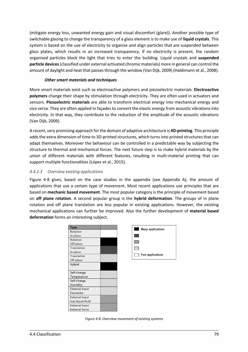
4.4 Classification 79
(mitigate energy loss, unwanted energy gain and visual discomfort (glare)). Another possible type of
switchable glazing to change the transparency of a glass element is to make use of liquid crystals. This
system is based on the use of electricity to organise and align particles that are suspended between
glass plates, which results in an increased transparency. If no electricity is present, the random
organised particles block the light that tries to enter the building. Liquid crystals and suspended
particle devices (classified under external activated chromic materials) more in general can control the
amount of daylight and heat that passes through the window (Van Dijk, 2009) (Haldimann et al., 2008).
Other smart materials and techniques
More smart materials exist such as electroactive polymers and piezoelectric materials. Electroactive
polymers change their shape by stimulation through electricity. They are often used in actuators and
sensors. Piezoelectric materials are able to transform electrical energy into mechanical energy and
vice versa. They are often applied in façades to convert the elastic energy from acoustic vibrations into
electricity. In that way, they contribute to the reduction of the amplitude of the acoustic vibrations
(Van Dijk, 2009).
A recent, very promising approach for the domain of adaptive architecture is 4D-printing. This principle
adds the extra dimension of time to 3D-printed structures, which turns into printed structures that can
adapt themselves. Moreover the behaviour can be controlled in a predictable way by subjecting the
structure to thermal and mechanical forces. The next future step is to make hybrid materials by the
union of different materials with different features, resulting in multi-material printing that can
support multiple functionalities (López et al., 2015).
4.4.2.3 Overview existing applications
Figure 4-8 gives, based on the case studies in the appendix (see Appendix A), the amount of
applications that use a certain type of movement. Most recent applications use principles that are
based on mechanic based movement. The most popular category is the principle of movement based
on off plane rotation. A second popular group is the hybrid deformation. The groups of in plane
rotation and off plane translation are less popular in existing applications. However, the existing
mechanical applications can further be improved. Also the further development of material based
deformation forms an interesting subject.
Figure 4-8: Overview movement of existing systems
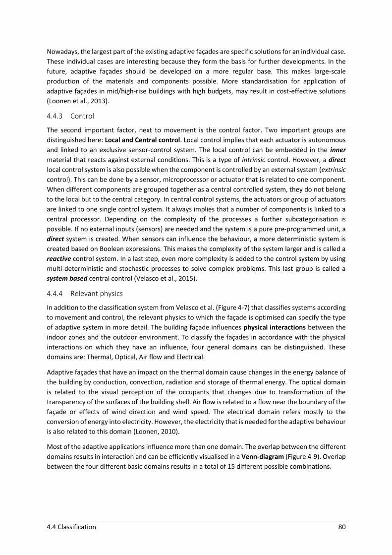
4.4 Classification 80
Nowadays, the largest part of the existing adaptive façades are specific solutions for an individual case.
These individual cases are interesting because they form the basis for further developments. In the
future, adaptive façades should be developed on a more regular base. This makes large-scale
production of the materials and components possible. More standardisation for application of
adaptive façades in mid/high-rise buildings with high budgets, may result in cost-effective solutions
(Loonen et al., 2013).
4.4.3 Control
The second important factor, next to movement is the control factor. Two important groups are
distinguished here: Local and Central control. Local control implies that each actuator is autonomous
and linked to an exclusive sensor-control system. The local control can be embedded in the inner
material that reacts against external conditions. This is a type of intrinsic control. However, a direct
local control system is also possible when the component is controlled by an external system (extrinsic
control). This can be done by a sensor, microprocessor or actuator that is related to one component.
When different components are grouped together as a central controlled system, they do not belong
to the local but to the central category. In central control systems, the actuators or group of actuators
are linked to one single control system. It always implies that a number of components is linked to a
central processor. Depending on the complexity of the processes a further subcategorisation is
possible. If no external inputs (sensors) are needed and the system is a pure pre-programmed unit, a
direct system is created. When sensors can influence the behaviour, a more deterministic system is
created based on Boolean expressions. This makes the complexity of the system larger and is called a
reactive control system. In a last step, even more complexity is added to the control system by using
multi-deterministic and stochastic processes to solve complex problems. This last group is called a
system based central control (Velasco et al., 2015).
4.4.4 Relevant physics
In addition to the classification system from Velasco et al. (Figure 4-7) that classifies systems according
to movement and control, the relevant physics to which the façade is optimised can specify the type
of adaptive system in more detail. The building façade influences physical interactions between the
indoor zones and the outdoor environment. To classify the façades in accordance with the physical
interactions on which they have an influence, four general domains can be distinguished. These
domains are: Thermal, Optical, Air flow and Electrical.
Adaptive façades that have an impact on the thermal domain cause changes in the energy balance of
the building by conduction, convection, radiation and storage of thermal energy. The optical domain
is related to the visual perception of the occupants that changes due to transformation of the
transparency of the surfaces of the building shell. Air flow is related to a flow near the boundary of the
façade or effects of wind direction and wind speed. The electrical domain refers mostly to the
conversion of energy into electricity. However, the electricity that is needed for the adaptive behaviour
is also related to this domain (Loonen, 2010).
Most of the adaptive applications influence more than one domain. The overlap between the different
domains results in interaction and can be efficiently visualised in a Venn-diagram (Figure 4-9). Overlap
between the four different basic domains results in a total of 15 different possible combinations.

4.4 Classification 81
Figure 4-9: The four physical domains and overlap zones (Adapted from (Loonen, 2010))
The thermal domain is present in almost all existing systems due to the fact that the thermal
environment is constantly changing. Optical effects play also very often a role in the systems, because
mostly controlled daylighting is part of the CABS strategy (Loonen et al., 2013). Studies (Loonen, 2010)
show that most adaptive façades can be classified in zone E, which is the thermo-optical overlap zone.
The second popular combination is the thermo-optical domain in combination with air flow
(represented by zone H) or in combination with electricity (zone O). In one third of the cases the air
flow domain is present in the strategy as well. According to the studies of Loonen (2010), the electrical
domain is more or less present in one fourth of the cases. This is mostly related to the use of
photovoltaics to gain energy (Loonen, 2010).
Figure 4-10 gives an overview of the different physical domains that are involved in the adaptive
systems studied in Appendix A. The thermal domain makes almost always part of the adaptive
structure. The red and orange zones show the areas with a lot of existing applications. The blue zones
are the areas with an intermediate amount of applications. The green areas indicate zones with a few
existing examples. The white areas are not really interesting because most adaptive systems have
automatically an influence on the thermal comfort in some way (direct or indirect). The same zones
and indexes as in Figure 4-9 are used.
Figure 4-10: Overview distribution of applications
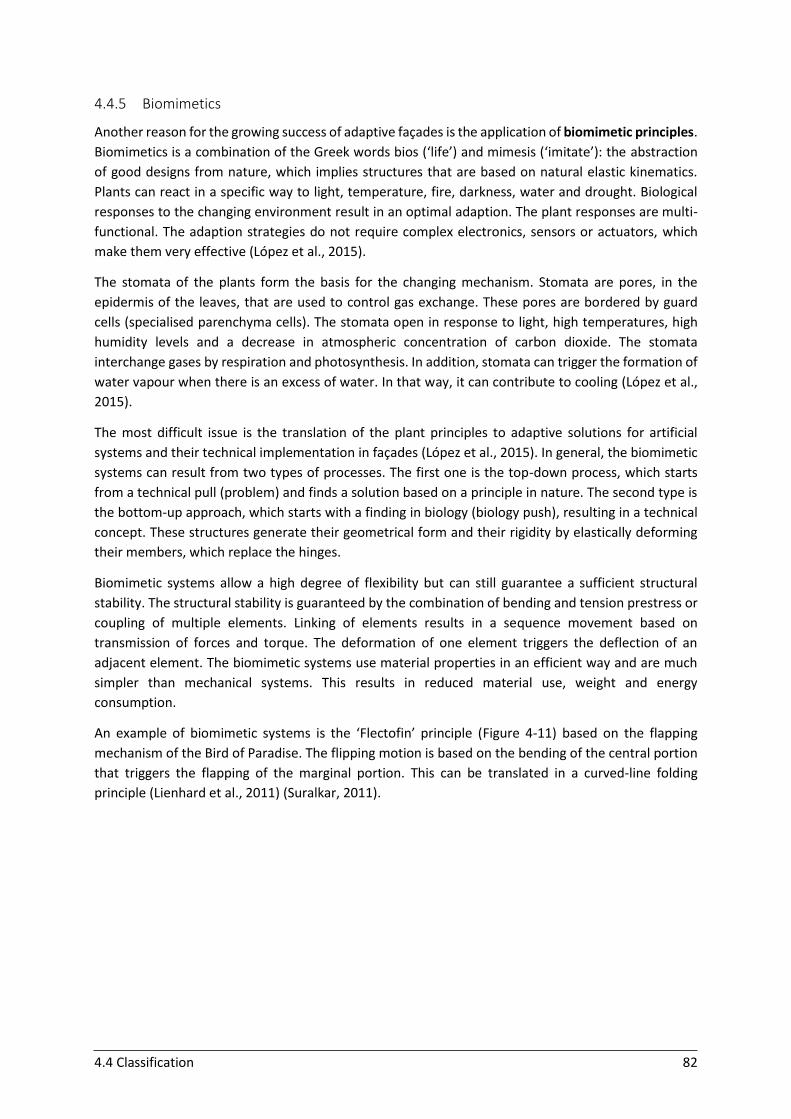
4.4 Classification 82
4.4.5 Biomimetics
Another reason for the growing success of adaptive façades is the application of biomimetic principles.
Biomimetics is a combination of the Greek words bios (‘life’) and mimesis (‘imitate’): the abstraction
of good designs from nature, which implies structures that are based on natural elastic kinematics.
Plants can react in a specific way to light, temperature, fire, darkness, water and drought. Biological
responses to the changing environment result in an optimal adaption. The plant responses are multi-
functional. The adaption strategies do not require complex electronics, sensors or actuators, which
make them very effective (López et al., 2015).
The stomata of the plants form the basis for the changing mechanism. Stomata are pores, in the
epidermis of the leaves, that are used to control gas exchange. These pores are bordered by guard
cells (specialised parenchyma cells). The stomata open in response to light, high temperatures, high
humidity levels and a decrease in atmospheric concentration of carbon dioxide. The stomata
interchange gases by respiration and photosynthesis. In addition, stomata can trigger the formation of
water vapour when there is an excess of water. In that way, it can contribute to cooling (López et al.,
2015).
The most difficult issue is the translation of the plant principles to adaptive solutions for artificial
systems and their technical implementation in façades (López et al., 2015). In general, the biomimetic
systems can result from two types of processes. The first one is the top-down process, which starts
from a technical pull (problem) and finds a solution based on a principle in nature. The second type is
the bottom-up approach, which starts with a finding in biology (biology push), resulting in a technical
concept. These structures generate their geometrical form and their rigidity by elastically deforming
their members, which replace the hinges.
Biomimetic systems allow a high degree of flexibility but can still guarantee a sufficient structural
stability. The structural stability is guaranteed by the combination of bending and tension prestress or
coupling of multiple elements. Linking of elements results in a sequence movement based on
transmission of forces and torque. The deformation of one element triggers the deflection of an
adjacent element. The biomimetic systems use material properties in an efficient way and are much
simpler than mechanical systems. This results in reduced material use, weight and energy
consumption.
An example of biomimetic systems is the ‘Flectofin’ principle (Figure 4-11) based on the flapping
mechanism of the Bird of Paradise. The flipping motion is based on the bending of the central portion
that triggers the flapping of the marginal portion. This can be translated in a curved-line folding
principle (Lienhard et al., 2011) (Suralkar, 2011).
4.4 Classification 83
Figure 4-11: Flectofin principle: a) theoretical position of the wings, b) real position of the wings pushing against each other, c)-e) opening of the wings due to bending of the backbone (Lienhard et al., 2011)
Another inspiration in nature is the ‘Dermaptera’ wing (Figure 4-12), which consists of two folding
mechanisms. A basic folding mechanism of four folded plates and a radial folding mechanism. An
external effort is necessary to start the folding process. After starting, it goes through a snap-through
and it is finally locked in the deployed shape (Hachem et al., 2014).
Figure 4-12: a) winged Dermaptera male, b) the hind wing of the Dermaptera, c) paper model simulating folding of the fan part of the hind wing (Hachem & Hanaor, 2006)

4.5 Conclusions and future perspectives 84
4.5 Conclusions and future perspectives
For a long time, the attention and efforts of building designers were focused on optimising the thermal
insulation of envelopes. Further upgrade of this envelopes is necessary to increase the energy
efficiency. This upgrade requires a shift from static to dynamic systems. In the future, the building’s
envelope will actively regulate the flow of heat, light, air and water from outdoor to indoor and vice
versa by acting as an interface that continuously and actively adapts to changing conditions (Perino &
Serra, 2015).
The low-technological examples of adaptive façades have the current trend to become more high-
technological and complex. However, simple constructions for adaptive façade elements can still be
very efficient and effective to obtain ‘zero energy’ houses. High-rise buildings require often more
technological and mechanised actuation and sensor systems. Systems equipped with new
performative materials, sensors, actuators and computerised intelligence increase in popularity to
control functionalities such as light, air flow, sound transmission, thermal transfer and interior
humidity quality. In addition, biological models are increasing in popularity and form the inspiration
for simple efficient adaptive façades (Kolarevic & Parlac, 2015) (Velikov & Thun, 2013).
Adaptive systems that have a movement principle that is mechanic based offer a lot of opportunities
for efficient control of energy use. Future systems could combine mechanic and material based
principles to create new concepts. The most applications that currently exist in the category of
mechanical deformation are based on an off plane rotation principle or hybrid deformation. Hybrid
movement is most interesting because it offers a wide range of possibilities.
A combination of possibilities for human adjustment and control of the systems with the avoidance of
user override, requires feedback systems. Extrinsic control of the systems is promising because this
type of operation control is most effective to combine automated strategies with personal control.
From the study about the different physical domains, it can be concluded that the thermal and optical
domains are closely coupled. Their fluctuating behaviour on daily and monthly level are often more
important than seasonal fluctuations. Therefore short-term adaptive systems look more interesting
for future developments. The Venn-diagram shows that the electrical domain has currently a low
number of applications. However, the integration of photovoltaic cells in the adaptive systems is very
promising to gain energy. A high performance can be obtained by combining the use of photovoltaic
cells with adaptive elements that improve thermal, optical and/or air flow quality. The current
objective is to create building envelopes that integrate multiple functionalities to obtain almost self-
sufficient systems in terms of energy. The challenge exists in developing these systems in a cost
efficient and standardised way to make it possible to use the systems in façades of multiple high-rise
buildings in the future.
Adaptive façades belong to a domain that is far from saturated and mature. There is a lack of
monitoring and evaluating of the performance of existing adaptive façades and post-occupancy
evaluation methods. In the future, new simulation tools and whole-life evaluation methods for the
adaptive façades as an integral part of the building should be developed. These tools and evaluation
methods are necessary because the development of adaptive concepts is often very challenging as a
result of the increased use of innovative technologies. The high risks make that designers often take
too conservative decisions. In the future, more expert modelling and experience will be required to
develop accurate evaluation tools (Favoino, 2015).
85
PART II. Design of prototypes

86
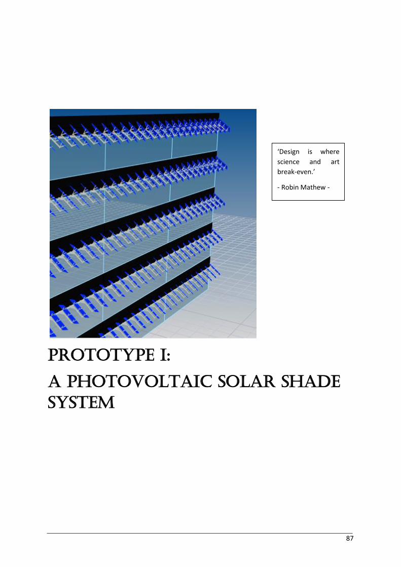
87
PROTOTYPE I:
a Photovoltaic Solar shade
system
‘Design is where
science and art
break-even.’
- Robin Mathew -
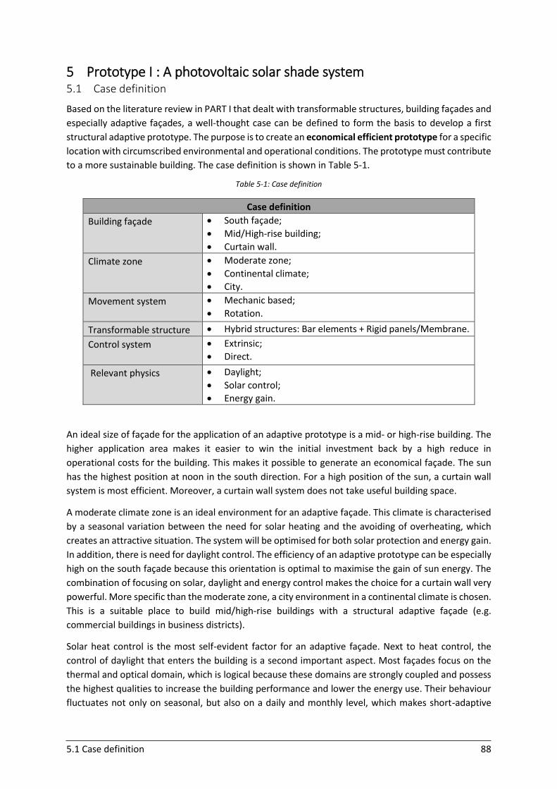
5.1 Case definition 88
5 Prototype I : A photovoltaic solar shade system 5.1 Case definition
Based on the literature review in PART I that dealt with transformable structures, building façades and
especially adaptive façades, a well-thought case can be defined to form the basis to develop a first
structural adaptive prototype. The purpose is to create an economical efficient prototype for a specific
location with circumscribed environmental and operational conditions. The prototype must contribute
to a more sustainable building. The case definition is shown in Table 5-1.
Table 5-1: Case definition
Case definition
Building façade
South façade;
Mid/High-rise building;
Curtain wall.
Climate zone
Moderate zone;
Continental climate;
City.
Movement system
Mechanic based;
Rotation.
Transformable structure Hybrid structures: Bar elements + Rigid panels/Membrane.
Control system
Extrinsic;
Direct.
Relevant physics
Daylight;
Solar control;
Energy gain.
An ideal size of façade for the application of an adaptive prototype is a mid- or high-rise building. The
higher application area makes it easier to win the initial investment back by a high reduce in
operational costs for the building. This makes it possible to generate an economical façade. The sun
has the highest position at noon in the south direction. For a high position of the sun, a curtain wall
system is most efficient. Moreover, a curtain wall system does not take useful building space.
A moderate climate zone is an ideal environment for an adaptive façade. This climate is characterised
by a seasonal variation between the need for solar heating and the avoiding of overheating, which
creates an attractive situation. The system will be optimised for both solar protection and energy gain.
In addition, there is need for daylight control. The efficiency of an adaptive prototype can be especially
high on the south façade because this orientation is optimal to maximise the gain of sun energy. The
combination of focusing on solar, daylight and energy control makes the choice for a curtain wall very
powerful. More specific than the moderate zone, a city environment in a continental climate is chosen.
This is a suitable place to build mid/high-rise buildings with a structural adaptive façade (e.g.
commercial buildings in business districts).
Solar heat control is the most self-evident factor for an adaptive façade. Next to heat control, the
control of daylight that enters the building is a second important aspect. Most façades focus on the
thermal and optical domain, which is logical because these domains are strongly coupled and possess
the highest qualities to increase the building performance and lower the energy use. Their behaviour
fluctuates not only on seasonal, but also on a daily and monthly level, which makes short-adaptive
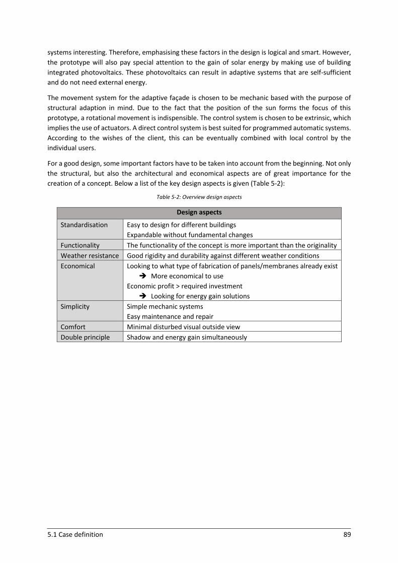
5.1 Case definition 89
systems interesting. Therefore, emphasising these factors in the design is logical and smart. However,
the prototype will also pay special attention to the gain of solar energy by making use of building
integrated photovoltaics. These photovoltaics can result in adaptive systems that are self-sufficient
and do not need external energy.
The movement system for the adaptive façade is chosen to be mechanic based with the purpose of
structural adaption in mind. Due to the fact that the position of the sun forms the focus of this
prototype, a rotational movement is indispensible. The control system is chosen to be extrinsic, which
implies the use of actuators. A direct control system is best suited for programmed automatic systems.
According to the wishes of the client, this can be eventually combined with local control by the
individual users.
For a good design, some important factors have to be taken into account from the beginning. Not only
the structural, but also the architectural and economical aspects are of great importance for the
creation of a concept. Below a list of the key design aspects is given (Table 5-2):
Table 5-2: Overview design aspects
Design aspects
Standardisation Easy to design for different buildings
Expandable without fundamental changes
Functionality The functionality of the concept is more important than the originality
Weather resistance Good rigidity and durability against different weather conditions
Economical Looking to what type of fabrication of panels/membranes already exist
More economical to use
Economic profit > required investment
Looking for energy gain solutions
Simplicity Simple mechanic systems
Easy maintenance and repair
Comfort Minimal disturbed visual outside view
Double principle Shadow and energy gain simultaneously
5.2 PV panels 90
5.2 PV panels
The defined case mentioned energy gain as a major focus aspect. The combination of providing shadow
with the gain of energy forms the starting point for the prototype. The first aspect in the design is to
choose between using rigid panels or membranes. To make a reasoned choice, two important factors
need to be considered. Firstly, the possibilities of PV (photovoltaic) panels have to be listed and
secondly, the stability and functional strength of the two choices has to be weighed against each other.
5.2.1 PV panels: general
5.2.1.1 Working principle
PV cells are made of semiconductors that generate electricity directly from sunlight (photoelectric
effect) with no pollution. The photons in solar light strike the PV panel and part of them are absorbed.
These absorbed photons break the atomic bond between electrons. The semiconductor structure in
the PV panel initiates an electric stream of free electrons (which is called a current) in a certain
direction (Web 5-01).
5.2.1.2 Types
The main distinction in PV panels is between the so called ‘first generation’ panels and ‘second
generation’ panels. BIPV panels (Building-integrated photovoltaic panels) can be of both types. The
‘first generation’ panels are cut from a single silicon crystal (monocrystalline – mono Si) or exist of a
slice cut from a block of silicon (polycrystalline – poly Si), with a large number of crystals. Polycrystalline
panels are slightly less expensive but a bit less efficient than monocrystalline panels on the same time.
The ‘second generation’ panels exist of the placement of a thin film (amorphous silicon or non-silicon
based) onto a surface. Besides amorphous silicon, other materials can be used as well (Jelle et al.,
2012).
In Table 5-3 an overview of a comparison between ‘first generation’ panels and ‘second generation’
panels is given (Jelle et al., 2012).
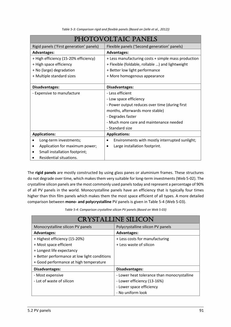
5.2 PV panels 91
Table 5-3: Comparison rigid and flexible panels (Based on (Jelle et al., 2012))
PHOTOVOLTAIc Panels
Rigid panels (‘First generation’ panels) Flexible panels (‘Second generation’ panels)
Advantages: Advantages:
+ High efficiency (15-20% efficiency)
+ High space efficiency
+ No (large) degradation
+ Multiple standard sizes
+ Less manufacturing costs + simple mass production
+ Flexible (foldable, rollable …) and lightweight
+ Better low light performance
+ More homogenous appearance
Disadvantages: Disadvantages:
- Expensive to manufacture
- Less efficient
- Low space efficiency
- Power output reduces over time (during first
months, afterwards more stable)
- Degrades faster
- Much more care and maintenance needed
- Standard size
Applications: Applications:
Long-term investments;
Application for maximum power;
Small installation footprint;
Residential situations.
Environments with mostly interrupted sunlight;
Large installation footprint.
The rigid panels are mostly constructed by using glass panes or aluminium frames. These structures
do not degrade over time, which makes them very suitable for long-term investments (Web 5-02). The
crystalline silicon panels are the most commonly used panels today and represent a percentage of 90%
of all PV panels in the world. Monocrystalline panels have an efficiency that is typically four times
higher than thin film panels which makes them the most space efficient of all types. A more detailed
comparison between mono- and polycrystalline PV panels is given in Table 5-4 (Web 5-03).
Table 5-4: Comparison crystalline silicon PV panels (Based on Web 5-03)
Crystalline Silicon
Monocrystalline silicon PV panels Polycrystalline silicon PV panels
Advantages: Advantages:
+ Highest efficiency (15-20%)
+ Most space efficient
+ Longest life expectancy
+ Better performance at low light conditions
+ Good performance at high temperature
+ Less costs for manufacturing
+ Less waste of silicon
Disadvantages: Disadvantages:
- Most expensive
- Lot of waste of silicon
- Lower heat tolerance than monocrystalline
- Lower efficiency (13-16%)
- Lower space efficiency
- No uniform look
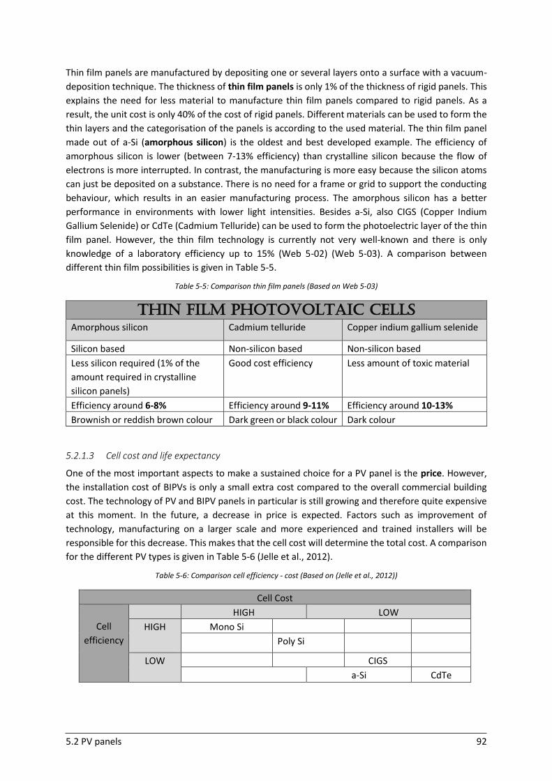
5.2 PV panels 92
Thin film panels are manufactured by depositing one or several layers onto a surface with a vacuum-
deposition technique. The thickness of thin film panels is only 1% of the thickness of rigid panels. This
explains the need for less material to manufacture thin film panels compared to rigid panels. As a
result, the unit cost is only 40% of the cost of rigid panels. Different materials can be used to form the
thin layers and the categorisation of the panels is according to the used material. The thin film panel
made out of a-Si (amorphous silicon) is the oldest and best developed example. The efficiency of
amorphous silicon is lower (between 7-13% efficiency) than crystalline silicon because the flow of
electrons is more interrupted. In contrast, the manufacturing is more easy because the silicon atoms
can just be deposited on a substance. There is no need for a frame or grid to support the conducting
behaviour, which results in an easier manufacturing process. The amorphous silicon has a better
performance in environments with lower light intensities. Besides a-Si, also CIGS (Copper Indium
Gallium Selenide) or CdTe (Cadmium Telluride) can be used to form the photoelectric layer of the thin
film panel. However, the thin film technology is currently not very well-known and there is only
knowledge of a laboratory efficiency up to 15% (Web 5-02) (Web 5-03). A comparison between
different thin film possibilities is given in Table 5-5.
Table 5-5: Comparison thin film panels (Based on Web 5-03)
5.2.1.3 Cell cost and life expectancy
One of the most important aspects to make a sustained choice for a PV panel is the price. However,
the installation cost of BIPVs is only a small extra cost compared to the overall commercial building
cost. The technology of PV and BIPV panels in particular is still growing and therefore quite expensive
at this moment. In the future, a decrease in price is expected. Factors such as improvement of
technology, manufacturing on a larger scale and more experienced and trained installers will be
responsible for this decrease. This makes that the cell cost will determine the total cost. A comparison
for the different PV types is given in Table 5-6 (Jelle et al., 2012).
Table 5-6: Comparison cell efficiency - cost (Based on (Jelle et al., 2012))
Cell Cost
Cell
efficiency
HIGH LOW
HIGH Mono Si
Poly Si
LOW CIGS
a-Si CdTe
Thin Film Photovoltaic cells
Amorphous silicon Cadmium telluride Copper indium gallium selenide
Silicon based Non-silicon based Non-silicon based
Less silicon required (1% of the
amount required in crystalline
silicon panels)
Good cost efficiency Less amount of toxic material
Efficiency around 6-8% Efficiency around 9-11% Efficiency around 10-13%
Brownish or reddish brown colour Dark green or black colour Dark colour
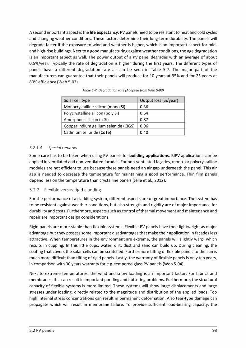
5.2 PV panels 93
A second important aspect is the life expectancy. PV panels need to be resistant to heat and cold cycles
and changing weather conditions. These factors determine their long-term durability. The panels will
degrade faster if the exposure to wind and weather is higher, which is an important aspect for mid-
and high-rise buildings. Next to a good manufacturing against weather conditions, the age degradation
is an important aspect as well. The power output of a PV panel degrades with an average of about
0.5%/year. Typically the rate of degradation is higher during the first years. The different types of
panels have a different degradation rate as can be seen in Table 5-7. The major part of the
manufacturers can guarantee that their panels will produce for 10 years at 95% and for 25 years at
80% efficiency (Web 5-03).
Table 5-7: Degradation rate (Adapted from Web 5-03)
Solar cell type Output loss (%/year)
Monocrystalline silicon (mono Si) 0.36
Polycrystalline silicon (poly Si) 0.64
Amorphous silicon (a-Si) 0.87
Copper indium gallium selenide (CIGS) 0.96
Cadmium telluride (CdTe) 0.40
5.2.1.4 Special remarks
Some care has to be taken when using PV panels for building applications. BIPV applications can be
applied in ventilated and non-ventilated façades. For non-ventilated façades, mono- or polycrystalline
modules are not efficient to use because these panels need an air gap underneath the panel. This air
gap is needed to decrease the temperature for maintaining a good performance. Thin film panels
depend less on the temperature than crystalline panels (Jelle et al., 2012).
5.2.2 Flexible versus rigid cladding
For the performance of a cladding system, different aspects are of great importance. The system has
to be resistant against weather conditions, but also strength and rigidity are of major importance for
durability and costs. Furthermore, aspects such as control of thermal movement and maintenance and
repair are important design considerations.
Rigid panels are more stable than flexible systems. Flexible PV panels have their lightweight as major
advantage but they possess some important disadvantages that make their application in façades less
attractive. When temperatures in the environment are extreme, the panels will slightly warp, which
results in cupping. In this little cups, water, dirt, dust and sand can build up. During cleaning, the
coating that covers the solar cells can be scratched. Furthermore tilting of flexible panels to the sun is
much more difficult than tilting of rigid panels. Lastly, the warranty of flexible panels is only ten years,
in comparison with 30 years warranty for e.g. tempered glass PV panels (Web 5-04).
Next to extreme temperatures, the wind and snow loading is an important factor. For fabrics and
membranes, this can result in important ponding and fluttering problems. Furthermore, the structural
capacity of flexible systems is more limited. These systems will show large displacements and large
stresses under loading, directly related to the magnitude and distribution of the applied loads. Too
high internal stress concentrations can result in permanent deformation. Also tear-type damage can
propagate which will result in membrane failure. To provide sufficient load-bearing capacity, the
5.3 Solar tracking 94
flexible systems need to be foreseen of double curvatures and pre-tensioning, which is difficult to apply
in a solar array system (Liapi, 2002) (Beccarelli, 2015).
During transformation of an adaptive façade system, the tension in the membrane surface will need
to be controlled to remain structurally effective. This is not easy and will result in important challenges
regarding the material behaviour. During the different transformation phases, it is important that the
geometrical stiffness is sufficiently high (Brancart et al., 2014).
There is currently not much experience with the application of membranes in façade systems due to
the complexity and limited tools to analyse the behaviour of these systems in different environmental
conditions. There are still several unknowns in using membranes as shading systems because only
simple systems are tested. At the moment, no improved building performance of membranes over
rigid systems is demonstrated (Beatini & Korkmaz, 2016).
5.2.3 Decision
In the previous parts, two main factors to investigate the choice between rigid panels or membranes
were investigated. Firstly, the different types of PV panels were discussed. Both flexible and rigid
panels are possible. Furthermore, different PV cells can be used. Secondly, the stability and strength
of the two options were compared. For a good durability and resistance against weather conditions
such as wind and snow loading, rigid panels are more advantageous. Moreover, membranes are more
complex to remain structurally efficient during transformation.
The previous research clearly points towards the choice for rigid panels. Thin film flexible panels will
have lower efficiency and on a façade, a space efficient system is important. Compared to weather
loads, the panel weight will only be a small fraction. Therefore, focusing on lightweight systems is not
an issue. Within the rigid panels, the choice between mono- and polycrystalline PV cells is still possible.
Due to the fact that the panels will be used in a ventilated curtain wall system, there will be no problem
with the performance of the crystalline panels.
5.3 Solar tracking
5.3.1 General
To improve the efficiency of PV panels, the principle of solar tracking is often used. Compared to fixed
systems, the trackers follow the position of the sun during the day and increase the collected sun
energy and amount of output power. By moving the PV panels, the angle of incidence of the solar rays
on the panel is closer to the optimal perpendicular position (further discussed in ‘5.3.2’). Two types of
track systems exist, the one-axis (single-axis) and the two-axis (dual-axis; double) trackers. Single-axis
trackers have only one degree of freedom, dual-axis trackers have two degrees of freedom. Different
types of single-axis trackers exist: horizontal single-axis trackers (north-south), vertical single-axis
trackers (east-west; azimuth tracking), tilted single-axis trackers and polar aligned single-axis trackers.
An overview of the differences between single and double tracking is given in Table 5-8 (Bakos, 2006)
(Web 5-05).
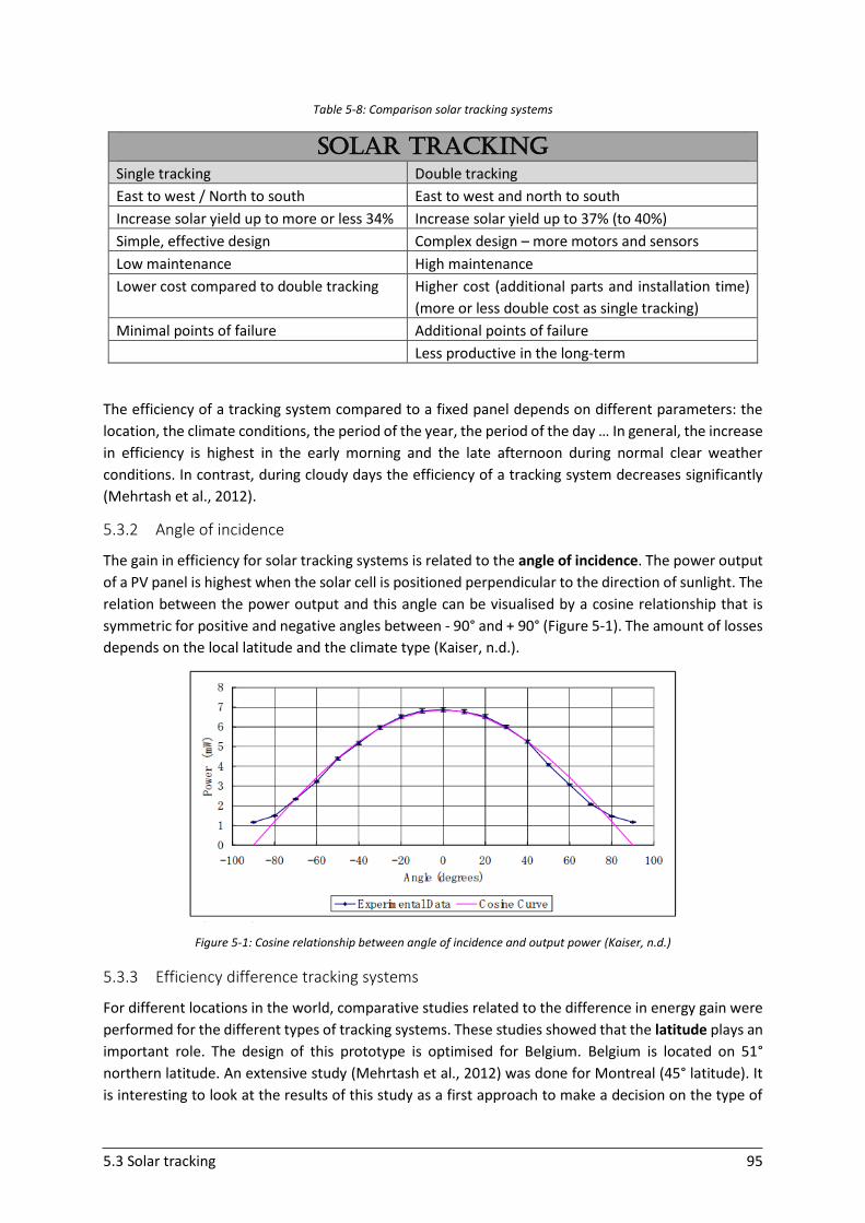
5.3 Solar tracking 95
Table 5-8: Comparison solar tracking systems
SOLAR Tracking
Single tracking Double tracking
East to west / North to south East to west and north to south
Increase solar yield up to more or less 34% Increase solar yield up to 37% (to 40%)
Simple, effective design Complex design – more motors and sensors
Low maintenance High maintenance
Lower cost compared to double tracking Higher cost (additional parts and installation time)
(more or less double cost as single tracking)
Minimal points of failure Additional points of failure
Less productive in the long-term
The efficiency of a tracking system compared to a fixed panel depends on different parameters: the
location, the climate conditions, the period of the year, the period of the day … In general, the increase
in efficiency is highest in the early morning and the late afternoon during normal clear weather
conditions. In contrast, during cloudy days the efficiency of a tracking system decreases significantly
(Mehrtash et al., 2012).
5.3.2 Angle of incidence
The gain in efficiency for solar tracking systems is related to the angle of incidence. The power output
of a PV panel is highest when the solar cell is positioned perpendicular to the direction of sunlight. The
relation between the power output and this angle can be visualised by a cosine relationship that is
symmetric for positive and negative angles between - 90° and + 90° (Figure 5-1). The amount of losses
depends on the local latitude and the climate type (Kaiser, n.d.).
Figure 5-1: Cosine relationship between angle of incidence and output power (Kaiser, n.d.)
5.3.3 Efficiency difference tracking systems
For different locations in the world, comparative studies related to the difference in energy gain were
performed for the different types of tracking systems. These studies showed that the latitude plays an
important role. The design of this prototype is optimised for Belgium. Belgium is located on 51°
northern latitude. An extensive study (Mehrtash et al., 2012) was done for Montreal (45° latitude). It
is interesting to look at the results of this study as a first approach to make a decision on the type of
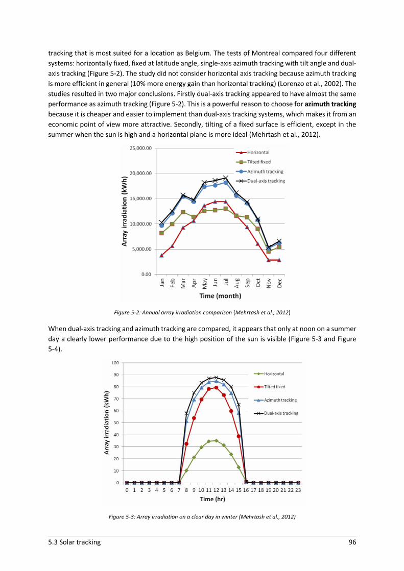
5.3 Solar tracking 96
tracking that is most suited for a location as Belgium. The tests of Montreal compared four different
systems: horizontally fixed, fixed at latitude angle, single-axis azimuth tracking with tilt angle and dual-
axis tracking (Figure 5-2). The study did not consider horizontal axis tracking because azimuth tracking
is more efficient in general (10% more energy gain than horizontal tracking) (Lorenzo et al., 2002). The
studies resulted in two major conclusions. Firstly dual-axis tracking appeared to have almost the same
performance as azimuth tracking (Figure 5-2). This is a powerful reason to choose for azimuth tracking
because it is cheaper and easier to implement than dual-axis tracking systems, which makes it from an
economic point of view more attractive. Secondly, tilting of a fixed surface is efficient, except in the
summer when the sun is high and a horizontal plane is more ideal (Mehrtash et al., 2012).
Figure 5-2: Annual array irradiation comparison (Mehrtash et al., 2012)
When dual-axis tracking and azimuth tracking are compared, it appears that only at noon on a summer
day a clearly lower performance due to the high position of the sun is visible (Figure 5-3 and Figure
5-4).
Figure 5-3: Array irradiation on a clear day in winter (Mehrtash et al., 2012)
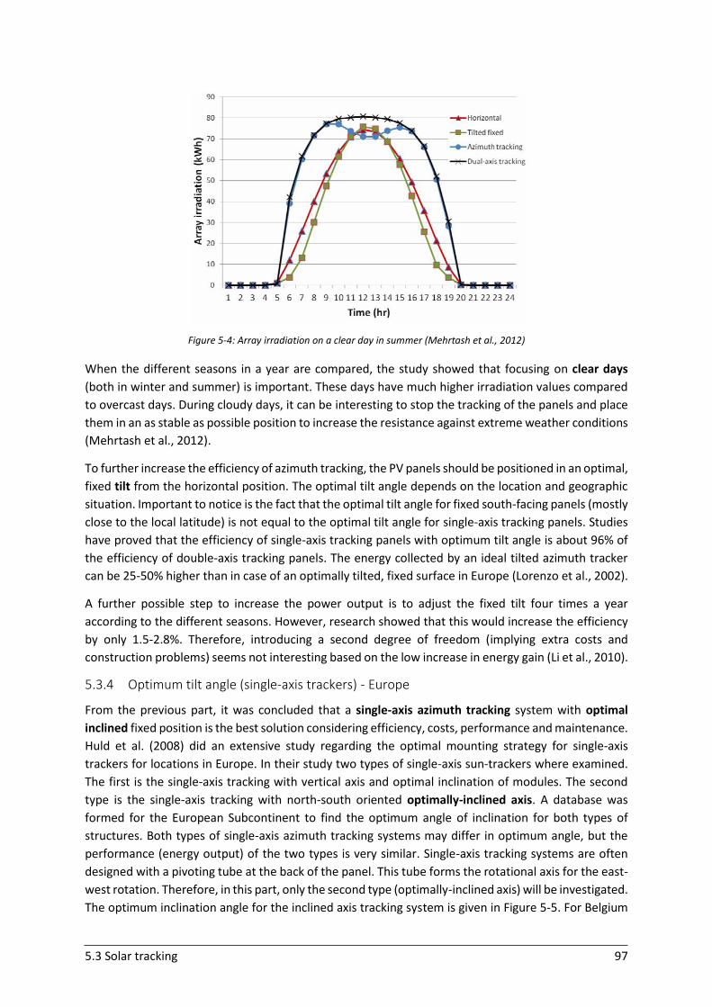
5.3 Solar tracking 97
Figure 5-4: Array irradiation on a clear day in summer (Mehrtash et al., 2012)
When the different seasons in a year are compared, the study showed that focusing on clear days
(both in winter and summer) is important. These days have much higher irradiation values compared
to overcast days. During cloudy days, it can be interesting to stop the tracking of the panels and place
them in an as stable as possible position to increase the resistance against extreme weather conditions
(Mehrtash et al., 2012).
To further increase the efficiency of azimuth tracking, the PV panels should be positioned in an optimal,
fixed tilt from the horizontal position. The optimal tilt angle depends on the location and geographic
situation. Important to notice is the fact that the optimal tilt angle for fixed south-facing panels (mostly
close to the local latitude) is not equal to the optimal tilt angle for single-axis tracking panels. Studies
have proved that the efficiency of single-axis tracking panels with optimum tilt angle is about 96% of
the efficiency of double-axis tracking panels. The energy collected by an ideal tilted azimuth tracker
can be 25-50% higher than in case of an optimally tilted, fixed surface in Europe (Lorenzo et al., 2002).
A further possible step to increase the power output is to adjust the fixed tilt four times a year
according to the different seasons. However, research showed that this would increase the efficiency
by only 1.5-2.8%. Therefore, introducing a second degree of freedom (implying extra costs and
construction problems) seems not interesting based on the low increase in energy gain (Li et al., 2010).
5.3.4 Optimum tilt angle (single-axis trackers) - Europe
From the previous part, it was concluded that a single-axis azimuth tracking system with optimal
inclined fixed position is the best solution considering efficiency, costs, performance and maintenance.
Huld et al. (2008) did an extensive study regarding the optimal mounting strategy for single-axis
trackers for locations in Europe. In their study two types of single-axis sun-trackers where examined.
The first is the single-axis tracking with vertical axis and optimal inclination of modules. The second
type is the single-axis tracking with north-south oriented optimally-inclined axis. A database was
formed for the European Subcontinent to find the optimum angle of inclination for both types of
structures. Both types of single-axis azimuth tracking systems may differ in optimum angle, but the
performance (energy output) of the two types is very similar. Single-axis tracking systems are often
designed with a pivoting tube at the back of the panel. This tube forms the rotational axis for the east-
west rotation. Therefore, in this part, only the second type (optimally-inclined axis) will be investigated.
The optimum inclination angle for the inclined axis tracking system is given in Figure 5-5. For Belgium
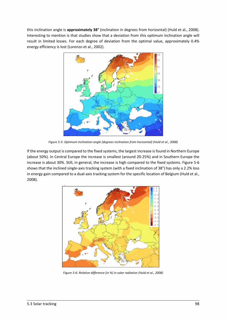
5.3 Solar tracking 98
this inclination angle is approximately 38° (inclination in degrees from horizontal) (Huld et al., 2008).
Interesting to mention is that studies show that a deviation from this optimum inclination angle will
result in limited losses. For each degree of deviation from the optimal value, approximately 0.4%
energy efficiency is lost (Lorenzo et al., 2002).
Figure 5-5: Optimum inclination angle (degrees inclination from horizontal) (Huld et al., 2008)
If the energy output is compared to the fixed systems, the largest increase is found in Northern Europe
(about 50%). In Central Europe the increase is smallest (around 20-25%) and in Southern Europe the
increase is about 30%. Still, in general, the increase is high compared to the fixed systems. Figure 5-6
shows that the inclined single-axis tracking system (with a fixed inclination of 38°) has only a 2.2% loss
in energy gain compared to a dual-axis tracking system for the specific location of Belgium (Huld et al.,
2008).
Figure 5-6: Relative difference (in %) in solar radiation (Huld et al., 2008)
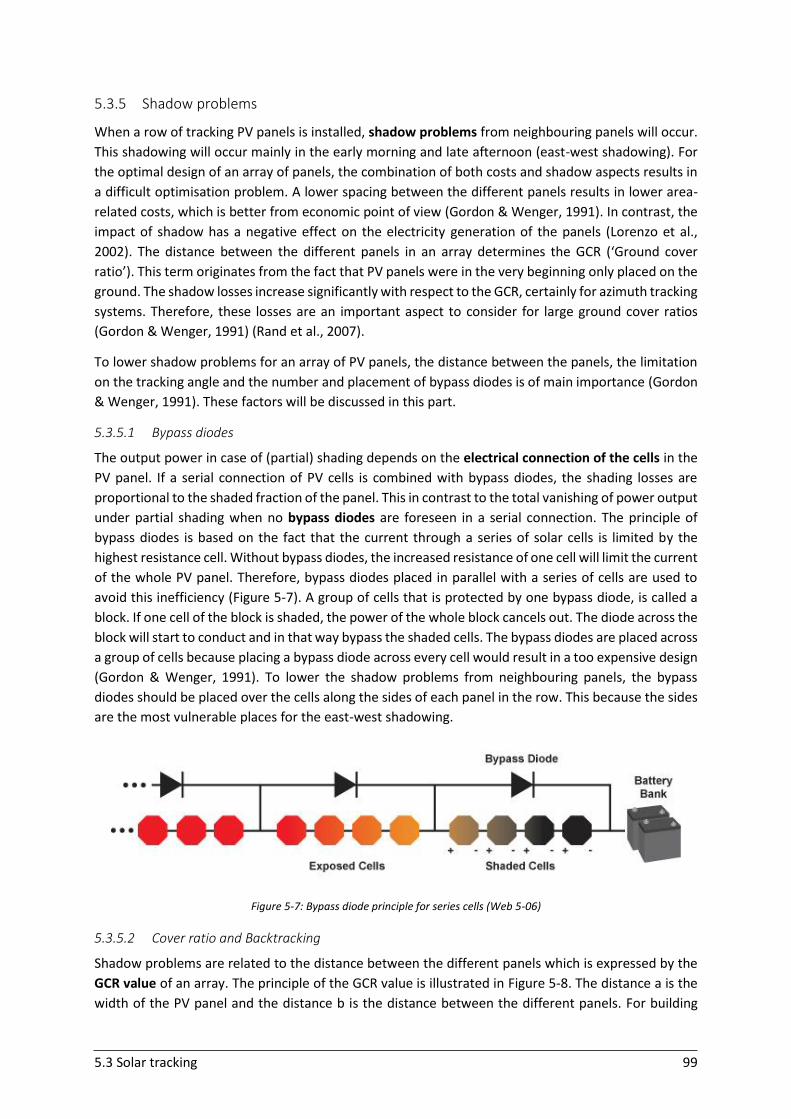
5.3 Solar tracking 99
5.3.5 Shadow problems
When a row of tracking PV panels is installed, shadow problems from neighbouring panels will occur.
This shadowing will occur mainly in the early morning and late afternoon (east-west shadowing). For
the optimal design of an array of panels, the combination of both costs and shadow aspects results in
a difficult optimisation problem. A lower spacing between the different panels results in lower area-
related costs, which is better from economic point of view (Gordon & Wenger, 1991). In contrast, the
impact of shadow has a negative effect on the electricity generation of the panels (Lorenzo et al.,
2002). The distance between the different panels in an array determines the GCR (‘Ground cover
ratio’). This term originates from the fact that PV panels were in the very beginning only placed on the
ground. The shadow losses increase significantly with respect to the GCR, certainly for azimuth tracking
systems. Therefore, these losses are an important aspect to consider for large ground cover ratios
(Gordon & Wenger, 1991) (Rand et al., 2007).
To lower shadow problems for an array of PV panels, the distance between the panels, the limitation
on the tracking angle and the number and placement of bypass diodes is of main importance (Gordon
& Wenger, 1991). These factors will be discussed in this part.
5.3.5.1 Bypass diodes
The output power in case of (partial) shading depends on the electrical connection of the cells in the
PV panel. If a serial connection of PV cells is combined with bypass diodes, the shading losses are
proportional to the shaded fraction of the panel. This in contrast to the total vanishing of power output
under partial shading when no bypass diodes are foreseen in a serial connection. The principle of
bypass diodes is based on the fact that the current through a series of solar cells is limited by the
highest resistance cell. Without bypass diodes, the increased resistance of one cell will limit the current
of the whole PV panel. Therefore, bypass diodes placed in parallel with a series of cells are used to
avoid this inefficiency (Figure 5-7). A group of cells that is protected by one bypass diode, is called a
block. If one cell of the block is shaded, the power of the whole block cancels out. The diode across the
block will start to conduct and in that way bypass the shaded cells. The bypass diodes are placed across
a group of cells because placing a bypass diode across every cell would result in a too expensive design
(Gordon & Wenger, 1991). To lower the shadow problems from neighbouring panels, the bypass
diodes should be placed over the cells along the sides of each panel in the row. This because the sides
are the most vulnerable places for the east-west shadowing.
Figure 5-7: Bypass diode principle for series cells (Web 5-06)
5.3.5.2 Cover ratio and Backtracking
Shadow problems are related to the distance between the different panels which is expressed by the
GCR value of an array. The principle of the GCR value is illustrated in Figure 5-8. The distance a is the
width of the PV panel and the distance b is the distance between the different panels. For building

5.3 Solar tracking 100
applications, it is important to make a space efficient system. Therefore lowering the GCR value in a
significant way is not possible.
Figure 5-8: Demonstration GCR principle
A recent technique to lower the problems of shadow losses and keeping a high GCR value is
backtracking. The concept of backtracking was developed to find a better balance between system
costs, array performance and long-term reliability. This non-ideal tracking technique is based on an
azimuth correction angle. Backtracking allows for a better energy performance for the same GCR value
since the energy losses due to increased incidence angles are smaller than the losses that result from
the shading. The normal conventional single-axis tracking system track the sun from east to west, at a
range of +/- 45-65°. During a backtracking cycle (illustrated in Figure 5-9), the panel array moves such
that no inter-array shading occurs. The array panels start from a zero tracking angle in the morning
(facing south) and end also in this position. They gradually rotate during the morning towards the east
at a certain rate such that no inter-array shading occurs. At a specific moment during the morning,
they reverse direction and rotate west to minimise the sun incidence angle. This reversion moment
depends on the season and location. During midday hours, the backtrack strategy is equivalent to the
conventional, ideal strategy. The gain of backtracking increases significantly with the GCR (Panico et
al., 1991) .
Figure 5-9: Demonstration backtracking strategy (Panico et al., 1991)
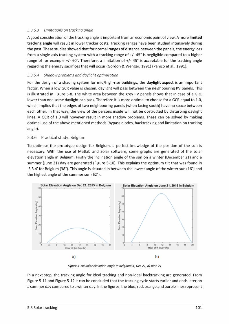
5.3 Solar tracking 101
5.3.5.3 Limitations on tracking angle
A good consideration of the tracking angle is important from an economic point of view. A more limited
tracking angle will result in lower tracker costs. Tracking ranges have been studied intensively during
the past. These studies showed that for normal ranges of distance between the panels, the energy loss
from a single-axis tracking system with a tracking range of +/- 45° is negligible compared to a higher
range of for example +/- 60°. Therefore, a limitation of +/- 45° is acceptable for the tracking angle
regarding the energy sacrifices that will occur (Gordon & Wenger, 1991) (Panico et al., 1991).
5.3.5.4 Shadow problems and daylight optimisation
For the design of a shading system for mid/high-rise buildings, the daylight aspect is an important
factor. When a low GCR value is chosen, daylight will pass between the neighbouring PV panels. This
is illustrated in Figure 5-8. The white area between the grey PV panels shows that in case of a GRC
lower than one some daylight can pass. Therefore it is more optimal to choose for a GCR equal to 1.0,
which implies that the edges of two neighbouring panels (when facing south) have no space between
each other. In that way, the view of the persons inside will not be obstructed by disturbing daylight
lines. A GCR of 1.0 will however result in more shadow problems. These can be solved by making
optimal use of the above mentioned methods (bypass diodes, backtracking and limitation on tracking
angle).
5.3.6 Practical study: Belgium
To optimise the prototype design for Belgium, a perfect knowledge of the position of the sun is
necessary. With the use of Matlab and Solar software, some graphs are generated of the solar
elevation angle in Belgium. Firstly the inclination angle of the sun on a winter (December 21) and a
summer (June 21) day are generated (Figure 5-10). This explains the optimum tilt that was found in
‘5.3.4’ for Belgium (38°). This angle is situated in between the lowest angle of the winter sun (16°) and
the highest angle of the summer sun (62°).
Figure 5-10: Solar elevation Angle in Belgium: a) Dec 21, b) June 21
In a next step, the tracking angle for ideal tracking and non-ideal backtracking are generated. From
Figure 5-11 and Figure 5-12 it can be concluded that the tracking cycle starts earlier and ends later on
a summer day compared to a winter day. In the figures, the blue, red, orange and purple lines represent
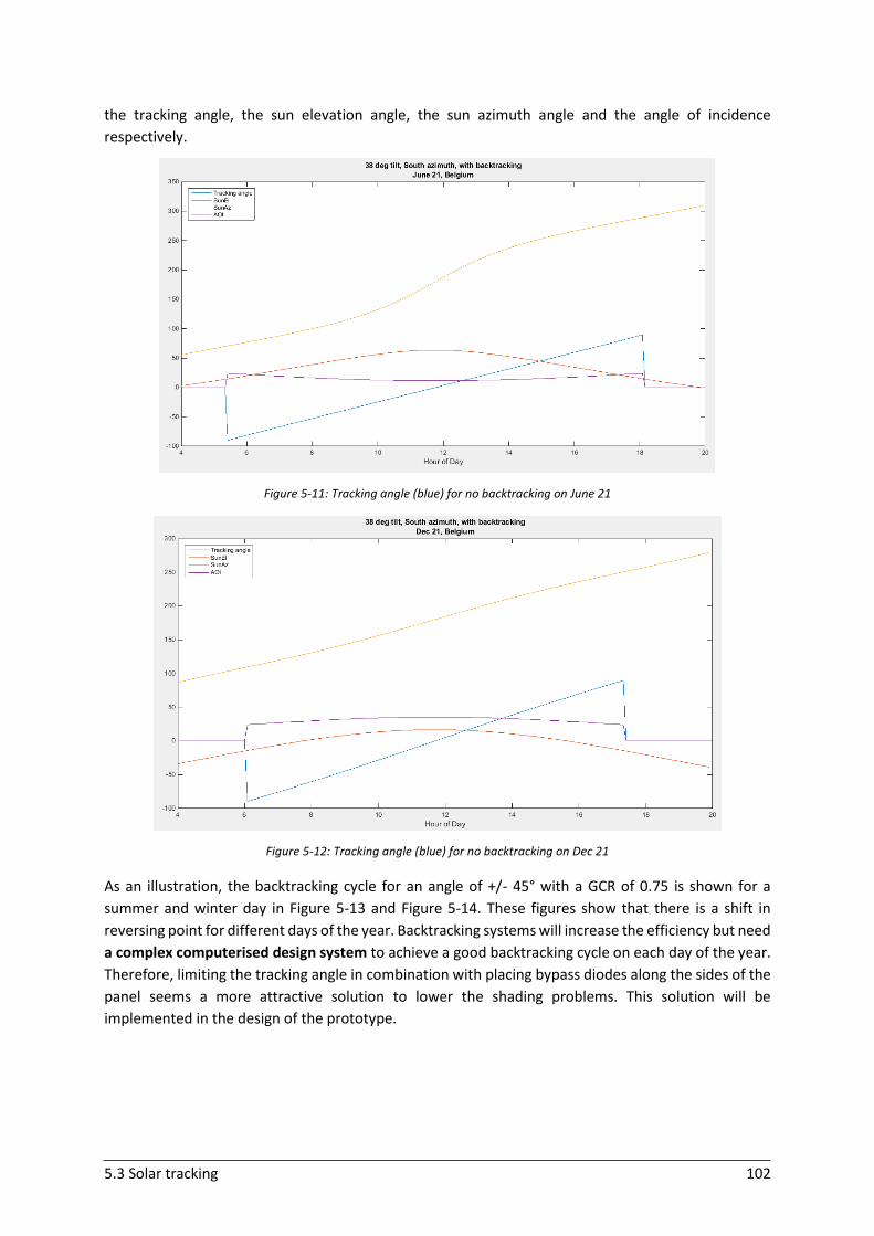
5.3 Solar tracking 102
the tracking angle, the sun elevation angle, the sun azimuth angle and the angle of incidence
respectively.
Figure 5-11: Tracking angle (blue) for no backtracking on June 21
Figure 5-12: Tracking angle (blue) for no backtracking on Dec 21
As an illustration, the backtracking cycle for an angle of +/- 45° with a GCR of 0.75 is shown for a
summer and winter day in Figure 5-13 and Figure 5-14. These figures show that there is a shift in
reversing point for different days of the year. Backtracking systems will increase the efficiency but need
a complex computerised design system to achieve a good backtracking cycle on each day of the year.
Therefore, limiting the tracking angle in combination with placing bypass diodes along the sides of the
panel seems a more attractive solution to lower the shading problems. This solution will be
implemented in the design of the prototype.
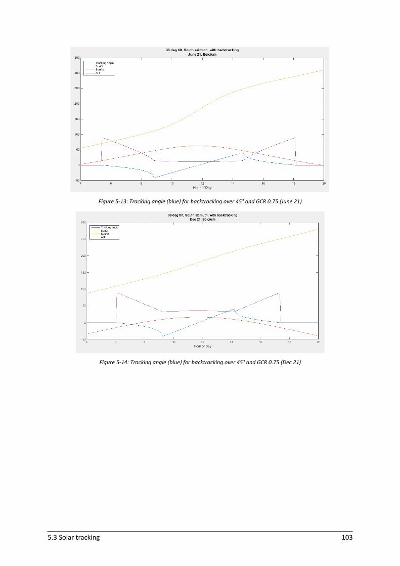
5.3 Solar tracking 103
Figure 5-13: Tracking angle (blue) for backtracking over 45° and GCR 0.75 (June 21)
Figure 5-14: Tracking angle (blue) for backtracking over 45° and GCR 0.75 (Dec 21)
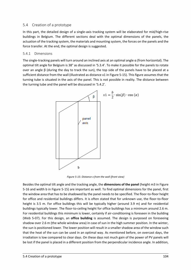
5.4 Creation of a prototype 104
5.4 Creation of a prototype
In this part, the detailed design of a single-axis tracking system will be elaborated for mid/high-rise
buildings in Belgium. The different sections deal with the optimal dimensions of the panels, the
actuation of the tracking system, the materials and mounting system, the forces on the panels and the
force transfer. At the end, the optimal design is suggested.
5.4.1 Dimensions
The single-tracking panels will turn around an inclined axis at an optimal angle α (from horizontal). The
optimal tilt angle for Belgium is 38° as discussed in ‘5.3.4’. To make it possible for the panels to rotate
over an angle β (during the day to track the sun), the top side of the panels have to be placed at a
sufficient distance from the wall (illustrated as distance x1 in Figure 5-15). This figure assumes that the
turning tube is situated in the axis of the panel. This is not possible in reality. The distance between
the turning tube and the panel will be discussed in ‘5.4.2’.
Figure 5-15: Distance x from the wall (front view)
Besides the optimal tilt angle and the tracking angle, the dimensions of the panel (height m3 in Figure
5-16 and width b in Figure 5-15) are important as well. To find optimal dimensions for the panel, first
the window area that has to be shadowed by the panel needs to be specified. The floor-to-floor height
for office and residential buildings differs. It is often stated that for unknown use, the floor-to-floor
height is 3.5 m. For office buildings this will be typically higher (around 3.9 m) and for residential
buildings typically lower. The floor-to-ceiling height for office buildings has a minimum around 2.6 m.
For residential buildings this minimum is lower, certainly if air-conditioning is foreseen in the building
(Web 5-07). For this design, an office building is assumed. The design is purposed on foreseeing
shadow over 2.6 m (the whole window area) in case of sun in the high summer position. In the winter,
the sun is positioned lower. The lower position will result in a smaller shadow area of the window such
that the heat of the sun can be used in an optimal way. As mentioned before, on overcast days, the
irradiation is low compared to clear days. On these days not much gain of the power of PV panels will
be lost if the panel is placed in a different position from the perpendicular incidence angle. In addition,
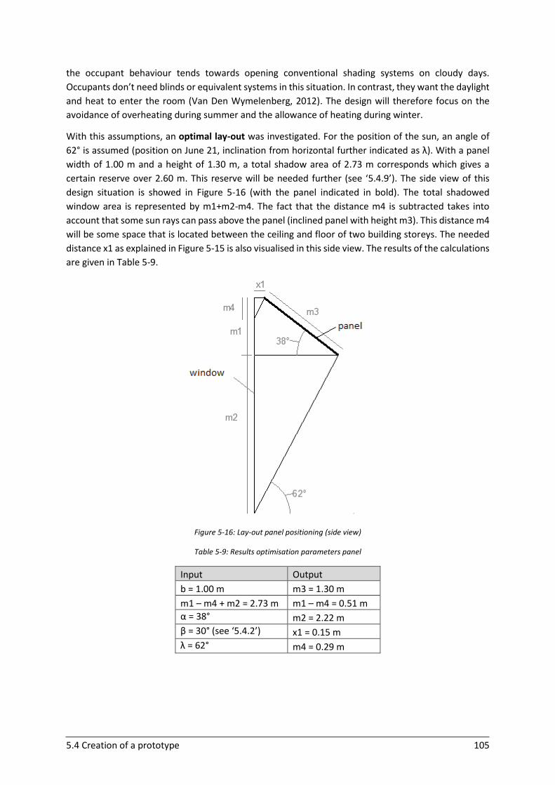
5.4 Creation of a prototype 105
the occupant behaviour tends towards opening conventional shading systems on cloudy days.
Occupants don’t need blinds or equivalent systems in this situation. In contrast, they want the daylight
and heat to enter the room (Van Den Wymelenberg, 2012). The design will therefore focus on the
avoidance of overheating during summer and the allowance of heating during winter.
With this assumptions, an optimal lay-out was investigated. For the position of the sun, an angle of
62° is assumed (position on June 21, inclination from horizontal further indicated as λ). With a panel
width of 1.00 m and a height of 1.30 m, a total shadow area of 2.73 m corresponds which gives a
certain reserve over 2.60 m. This reserve will be needed further (see ‘5.4.9’). The side view of this
design situation is showed in Figure 5-16 (with the panel indicated in bold). The total shadowed
window area is represented by m1+m2-m4. The fact that the distance m4 is subtracted takes into
account that some sun rays can pass above the panel (inclined panel with height m3). This distance m4
will be some space that is located between the ceiling and floor of two building storeys. The needed
distance x1 as explained in Figure 5-15 is also visualised in this side view. The results of the calculations
are given in Table 5-9.
Figure 5-16: Lay-out panel positioning (side view)
Table 5-9: Results optimisation parameters panel
Input Output
b = 1.00 m m3 = 1.30 m
m1 – m4 + m2 = 2.73 m m1 – m4 = 0.51 m
α = 38° m2 = 2.22 m
β = 30° (see ‘5.4.2’) x1 = 0.15 m
λ = 62° m4 = 0.29 m
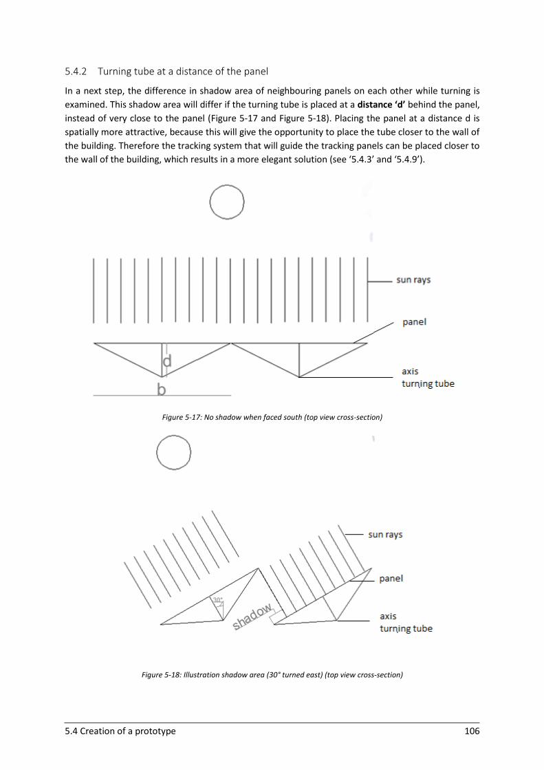
5.4 Creation of a prototype 106
5.4.2 Turning tube at a distance of the panel
In a next step, the difference in shadow area of neighbouring panels on each other while turning is
examined. This shadow area will differ if the turning tube is placed at a distance ‘d’ behind the panel,
instead of very close to the panel (Figure 5-17 and Figure 5-18). Placing the panel at a distance d is
spatially more attractive, because this will give the opportunity to place the tube closer to the wall of
the building. Therefore the tracking system that will guide the tracking panels can be placed closer to
the wall of the building, which results in a more elegant solution (see ‘5.4.3’ and ‘5.4.9’).
Figure 5-17: No shadow when faced south (top view cross-section)
Figure 5-18: Illustration shadow area (30° turned east) (top view cross-section)

5.4 Creation of a prototype 107
Figure 5-19 shows the tracking principle on the final designed prototype (based on the further
calculations and investigation in this chapter)
Figure 5-19: Illustration tracking principle: a) turning west, b) turning east
In Table 5-10, the results of the investigation of the shadow area are shown. The left column shows
the results in the extreme case of the tube being placed at the centre of the panel (at a distance d
equal to zero). This will in reality never occur. The angle β shows the tracking angle. The results are
compared for a distance d more far from the panel, and for a distance d close to the panel (0.03 m). It
can be seen that the difference in shadow area is negligible for the two cases. Certainly compared to
the advantage of placing the tube closer to the wall (more elegant structure and tracking system see
‘5.4.3’). If the solution of a larger distance d is implemented, it has to be ensured that the profile that
connects the panel to the tube is certainly stiff enough.
In Table 5-10 the shadow area is also compared to half the width of a panel in the column ‘fraction of
half panel’. From this column it can be concluded that this fraction is quite large at 45° compared to
30°. Therefore it seems more reasonable in terms of energy gain to only track to +/- 30° east and west
in combination with placing bypass diodes in parallel to the series PV cells at the sides of the PV panel.
This decision is supported by the cosine relationship between the power output and angle of incidence
as explained in ‘5.3.2’. If only 15° is deviated from the perpendicular incidence angle, the amount of
power loss is almost negligible as this angle of incidence is still situated in the top of the cosine profile
(Figure 5-1). When a limited tracking angle of 30° is set, the distance d to the panel can be lowered. A
more ideal distance in that case is 0.25 m.
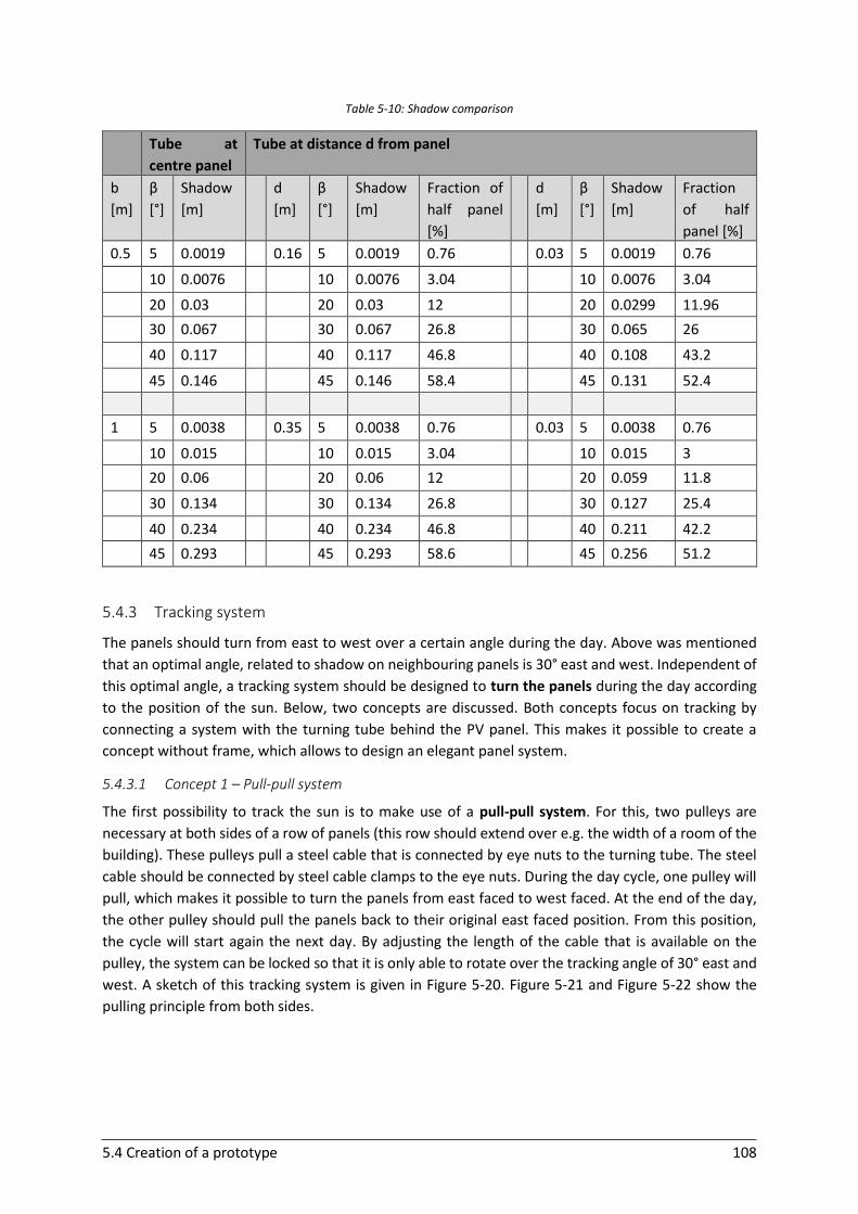
5.4 Creation of a prototype 108
Table 5-10: Shadow comparison
Tube at
centre panel
Tube at distance d from panel
b
[m]
β
[°]
Shadow
[m]
d
[m]
β
[°]
Shadow
[m]
Fraction of
half panel
[%]
d
[m]
β
[°]
Shadow
[m]
Fraction
of half
panel [%]
0.5 5 0.0019 0.16 5 0.0019 0.76 0.03 5 0.0019 0.76
10 0.0076 10 0.0076 3.04 10 0.0076 3.04
20 0.03 20 0.03 12 20 0.0299 11.96
30 0.067 30 0.067 26.8 30 0.065 26
40 0.117 40 0.117 46.8 40 0.108 43.2
45 0.146 45 0.146 58.4 45 0.131 52.4
1 5 0.0038 0.35 5 0.0038 0.76 0.03 5 0.0038 0.76
10 0.015 10 0.015 3.04 10 0.015 3
20 0.06 20 0.06 12 20 0.059 11.8
30 0.134 30 0.134 26.8 30 0.127 25.4
40 0.234 40 0.234 46.8 40 0.211 42.2
45 0.293 45 0.293 58.6 45 0.256 51.2
5.4.3 Tracking system
The panels should turn from east to west over a certain angle during the day. Above was mentioned
that an optimal angle, related to shadow on neighbouring panels is 30° east and west. Independent of
this optimal angle, a tracking system should be designed to turn the panels during the day according
to the position of the sun. Below, two concepts are discussed. Both concepts focus on tracking by
connecting a system with the turning tube behind the PV panel. This makes it possible to create a
concept without frame, which allows to design an elegant panel system.
5.4.3.1 Concept 1 – Pull-pull system
The first possibility to track the sun is to make use of a pull-pull system. For this, two pulleys are
necessary at both sides of a row of panels (this row should extend over e.g. the width of a room of the
building). These pulleys pull a steel cable that is connected by eye nuts to the turning tube. The steel
cable should be connected by steel cable clamps to the eye nuts. During the day cycle, one pulley will
pull, which makes it possible to turn the panels from east faced to west faced. At the end of the day,
the other pulley should pull the panels back to their original east faced position. From this position,
the cycle will start again the next day. By adjusting the length of the cable that is available on the
pulley, the system can be locked so that it is only able to rotate over the tracking angle of 30° east and
west. A sketch of this tracking system is given in Figure 5-20. Figure 5-21 and Figure 5-22 show the
pulling principle from both sides.
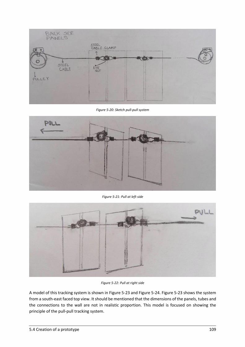
5.4 Creation of a prototype 109
Figure 5-20: Sketch pull-pull system
Figure 5-21: Pull at left side
Figure 5-22: Pull at right side
A model of this tracking system is shown in Figure 5-23 and Figure 5-24. Figure 5-23 shows the system
from a south-east faced top view. It should be mentioned that the dimensions of the panels, tubes and
the connections to the wall are not in realistic proportion. This model is focused on showing the
principle of the pull-pull tracking system.
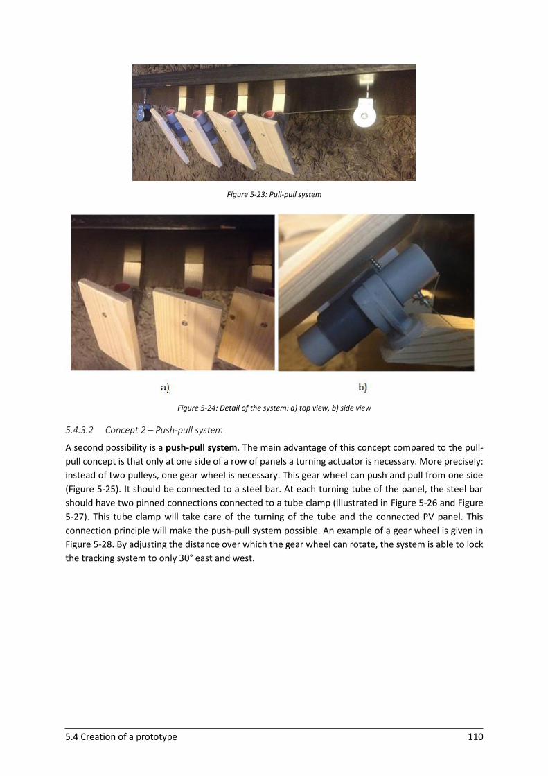
5.4 Creation of a prototype 110
Figure 5-23: Pull-pull system
Figure 5-24: Detail of the system: a) top view, b) side view
5.4.3.2 Concept 2 – Push-pull system
A second possibility is a push-pull system. The main advantage of this concept compared to the pull-
pull concept is that only at one side of a row of panels a turning actuator is necessary. More precisely:
instead of two pulleys, one gear wheel is necessary. This gear wheel can push and pull from one side
(Figure 5-25). It should be connected to a steel bar. At each turning tube of the panel, the steel bar
should have two pinned connections connected to a tube clamp (illustrated in Figure 5-26 and Figure
5-27). This tube clamp will take care of the turning of the tube and the connected PV panel. This
connection principle will make the push-pull system possible. An example of a gear wheel is given in
Figure 5-28. By adjusting the distance over which the gear wheel can rotate, the system is able to lock
the tracking system to only 30° east and west.
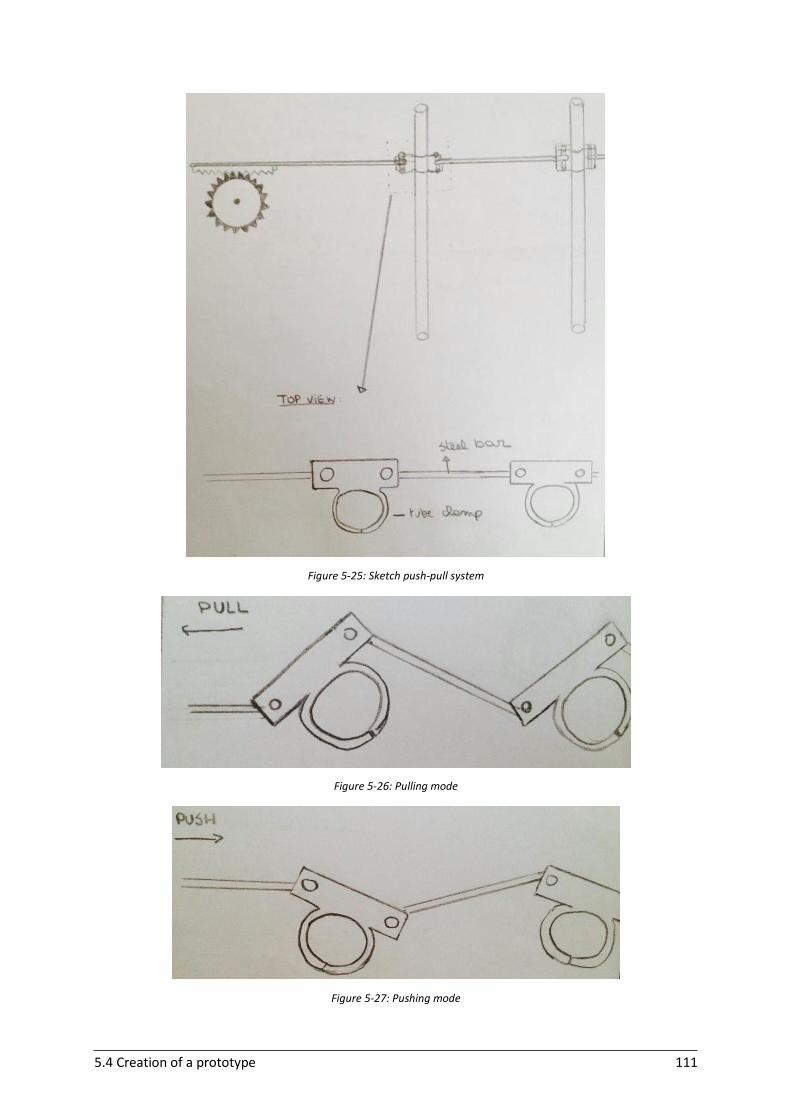
5.4 Creation of a prototype 111
Figure 5-25: Sketch push-pull system
Figure 5-26: Pulling mode
Figure 5-27: Pushing mode
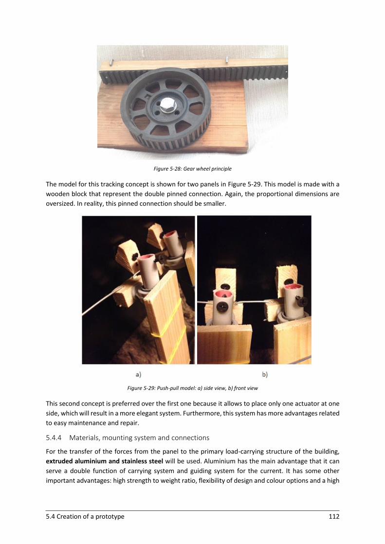
5.4 Creation of a prototype 112
Figure 5-28: Gear wheel principle
The model for this tracking concept is shown for two panels in Figure 5-29. This model is made with a
wooden block that represent the double pinned connection. Again, the proportional dimensions are
oversized. In reality, this pinned connection should be smaller.
Figure 5-29: Push-pull model: a) side view, b) front view
This second concept is preferred over the first one because it allows to place only one actuator at one
side, which will result in a more elegant system. Furthermore, this system has more advantages related
to easy maintenance and repair.
5.4.4 Materials, mounting system and connections
For the transfer of the forces from the panel to the primary load-carrying structure of the building,
extruded aluminium and stainless steel will be used. Aluminium has the main advantage that it can
serve a double function of carrying system and guiding system for the current. It has some other
important advantages: high strength to weight ratio, flexibility of design and colour options and a high
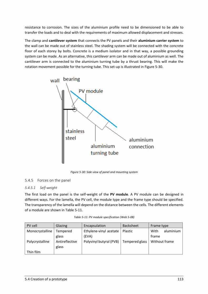
5.4 Creation of a prototype 113
resistance to corrosion. The sizes of the aluminium profile need to be dimensioned to be able to
transfer the loads and to deal with the requirements of maximum allowed displacement and stresses.
The clamp and cantilever system that connects the PV panels and their aluminium carrier system to
the wall can be made out of stainless steel. The shading system will be connected with the concrete
floor of each storey by bolts. Concrete is a medium isolator and in that way, a possible grounding
system can be made. As an alternative, this cantilever arm can be made out of aluminium as well. The
cantilever arm is connected to the aluminium turning tube by a thrust bearing. This will make the
rotation movement possible for the turning tube. This set-up is illustrated in Figure 5-30.
Figure 5-30: Side view of panel and mounting system
5.4.5 Forces on the panel
5.4.5.1 Self-weight
The first load on the panel is the self-weight of the PV module. A PV module can be designed in
different ways. For the lamella, the PV cell, the module type and the frame type should be specified.
The transparency of the lamella will depend on the distance between the cells. The different elements
of a module are shown in Table 5-11.
Table 5-11: PV module specification (Web 5-08)
PV cell Glazing Encapsulation Backsheet Frame type
Monocrystalline Tempered
glass
Ethylene-vinyl acetate
(EVA)
Plastic With aluminium
frame
Polycrystalline Antireflective
glass
Polyvinyl butyral (PVB) Tempered glass Without frame
Thin film
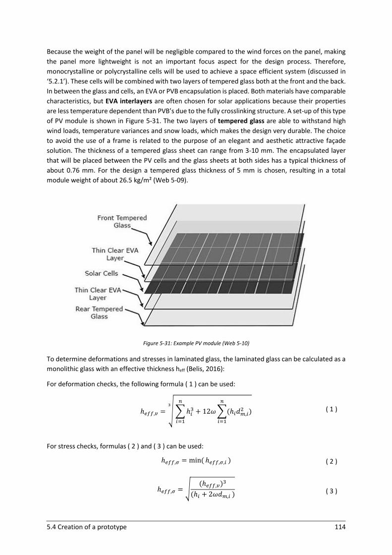
5.4 Creation of a prototype 114
Because the weight of the panel will be negligible compared to the wind forces on the panel, making
the panel more lightweight is not an important focus aspect for the design process. Therefore,
monocrystalline or polycrystalline cells will be used to achieve a space efficient system (discussed in
‘5.2.1’). These cells will be combined with two layers of tempered glass both at the front and the back.
In between the glass and cells, an EVA or PVB encapsulation is placed. Both materials have comparable
characteristics, but EVA interlayers are often chosen for solar applications because their properties
are less temperature dependent than PVB’s due to the fully crosslinking structure. A set-up of this type
of PV module is shown in Figure 5-31. The two layers of tempered glass are able to withstand high
wind loads, temperature variances and snow loads, which makes the design very durable. The choice
to avoid the use of a frame is related to the purpose of an elegant and aesthetic attractive façade
solution. The thickness of a tempered glass sheet can range from 3-10 mm. The encapsulated layer
that will be placed between the PV cells and the glass sheets at both sides has a typical thickness of
about 0.76 mm. For the design a tempered glass thickness of 5 mm is chosen, resulting in a total
module weight of about 26.5 kg/m² (Web 5-09).
Figure 5-31: Example PV module (Web 5-10)
To determine deformations and stresses in laminated glass, the laminated glass can be calculated as a
monolithic glass with an effective thickness heff (Belis, 2016):
For deformation checks, the following formula ( 1 ) can be used:
ℎ𝑒𝑓𝑓,𝑣 = √ ∑ ℎ𝑖3
𝑛
𝑖=1
+ 12𝜔 ∑(ℎ𝑖𝑑𝑚,𝑖2 )
𝑛
𝑖=1
3
( 1 )
For stress checks, formulas ( 2 ) and ( 3 ) can be used:
ℎ𝑒𝑓𝑓,𝜎 = min( ℎ𝑒𝑓𝑓,𝜎,𝑖 )
( 2 )
ℎ𝑒𝑓𝑓,𝜎 = √
(ℎ𝑒𝑓𝑓,𝑣)3
(ℎ𝑖 + 2𝜔𝑑𝑚,𝑖 )
( 3 )
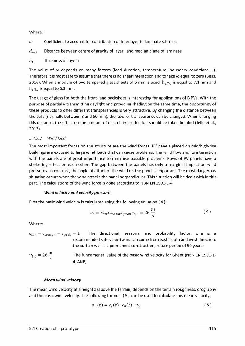
5.4 Creation of a prototype 115
Where:
𝜔 Coefficient to account for contribution of interlayer to laminate stiffness
𝑑𝑚,𝑖 Distance between centre of gravity of layer i and median plane of laminate
ℎ𝑖 Thickness of layer i
The value of ω depends on many factors (load duration, temperature, boundary conditions …).
Therefore it is most safe to assume that there is no shear interaction and to take ω equal to zero (Belis,
2016). When a module of two tempered glass sheets of 5 mm is used, heff,σ is equal to 7.1 mm and
heff,v is equal to 6.3 mm.
The usage of glass for both the front- and backsheet is interesting for applications of BIPVs. With the
purpose of partially transmitting daylight and providing shading on the same time, the opportunity of
these products to offer different transparencies is very attractive. By changing the distance between
the cells (normally between 3 and 50 mm), the level of transparency can be changed. When changing
this distance, the effect on the amount of electricity production should be taken in mind (Jelle et al.,
2012).
5.4.5.2 Wind load
The most important forces on the structure are the wind forces. PV panels placed on mid/high-rise
buildings are exposed to large wind loads that can cause problems. The wind flow and its interaction
with the panels are of great importance to minimise possible problems. Rows of PV panels have a
sheltering effect on each other. The gap between the panels has only a marginal impact on wind
pressures. In contrast, the angle of attack of the wind on the panel is important. The most dangerous
situation occurs when the wind attacks the panel perpendicular. This situation will be dealt with in this
part. The calculations of the wind force is done according to NBN EN 1991-1-4.
Wind velocity and velocity pressure
First the basic wind velocity is calculated using the following equation ( 4 ):
𝑣𝑏 = 𝑐𝑑𝑖𝑟𝑐𝑠𝑒𝑎𝑠𝑜𝑛𝑐𝑝𝑟𝑜𝑏𝑣𝑏,0 = 26 𝑚
𝑠 ( 4 )
Where:
𝑐𝑑𝑖𝑟 = 𝑐𝑠𝑒𝑎𝑠𝑜𝑛 = cprob = 1 The directional, seasonal and probability factor: one is a
recommended safe value (wind can come from east, south and west direction,
the curtain wall is a permanent construction, return period of 50 years)
𝑣𝑏,0 = 26 m
s The fundamental value of the basic wind velocity for Ghent (NBN EN 1991-1-
4 ANB)
Mean wind velocity
The mean wind velocity at a height z (above the terrain) depends on the terrain roughness, orography
and the basic wind velocity. The following formula ( 5 ) can be used to calculate this mean velocity:
𝑣𝑚(𝑧) = 𝑐𝑟(𝑧) ∙ 𝑐0(𝑧) ∙ 𝑣𝑏
( 5 )
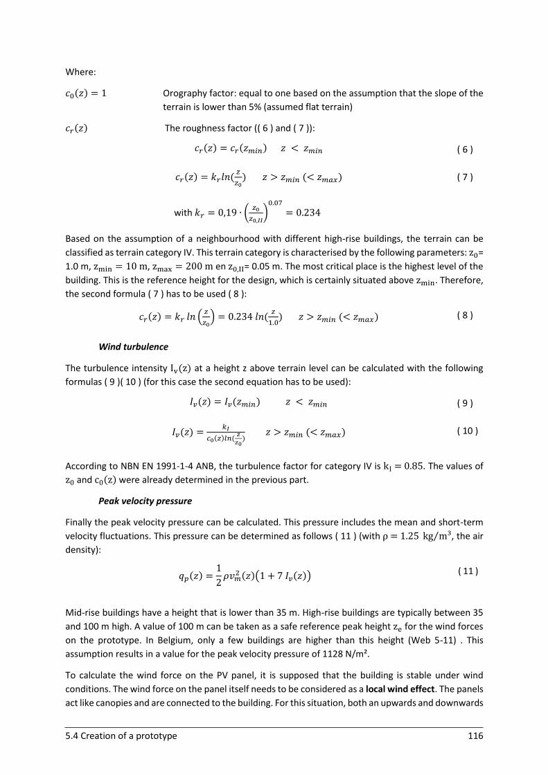
5.4 Creation of a prototype 116
Where:
𝑐0(𝑧) = 1 Orography factor: equal to one based on the assumption that the slope of the
terrain is lower than 5% (assumed flat terrain)
𝑐𝑟(𝑧) The roughness factor (( 6 ) and ( 7 )):
𝑐𝑟(𝑧) = 𝑐𝑟(𝑧𝑚𝑖𝑛) 𝑧 < 𝑧𝑚𝑖𝑛
( 6 )
𝑐𝑟(𝑧) = 𝑘𝑟𝑙𝑛 (𝑧
𝑧0) 𝑧 > 𝑧𝑚𝑖𝑛 (< 𝑧𝑚𝑎𝑥)
( 7 )
with 𝑘𝑟 = 0,19 ∙ (𝑧0
𝑧0,𝐼𝐼)
0.07
= 0.234
Based on the assumption of a neighbourhood with different high-rise buildings, the terrain can be
classified as terrain category IV. This terrain category is characterised by the following parameters: z0=
1.0 m, zmin = 10 m, zmax = 200 m en z0,II= 0.05 m. The most critical place is the highest level of the
building. This is the reference height for the design, which is certainly situated above zmin. Therefore,
the second formula ( 7 ) has to be used ( 8 ):
𝑐𝑟(𝑧) = 𝑘𝑟 𝑙𝑛 (𝑧
𝑧0) = 0.234 𝑙𝑛 (
𝑧
1.0) 𝑧 > 𝑧𝑚𝑖𝑛 (< 𝑧𝑚𝑎𝑥)
( 8 )
Wind turbulence
The turbulence intensity Iv(z) at a height z above terrain level can be calculated with the following
formulas ( 9 )( 10 ) (for this case the second equation has to be used):
𝐼𝑣(𝑧) = 𝐼𝑣(𝑧𝑚𝑖𝑛) 𝑧 < 𝑧𝑚𝑖𝑛
( 9 )
𝐼𝑣(𝑧) =𝑘𝐼
𝑐0(𝑧)𝑙𝑛 (𝑧
𝑧0) 𝑧 > 𝑧𝑚𝑖𝑛 (< 𝑧𝑚𝑎𝑥)
( 10 )
According to NBN EN 1991-1-4 ANB, the turbulence factor for category IV is kI = 0.85. The values of
z0 and c0(z) were already determined in the previous part.
Peak velocity pressure
Finally the peak velocity pressure can be calculated. This pressure includes the mean and short-term
velocity fluctuations. This pressure can be determined as follows ( 11 ) (with ρ = 1.25 kg m³⁄ , the air
density):
𝑞𝑝(𝑧) =1
2𝜌𝑣𝑚
2 (𝑧)(1 + 7 𝐼𝑣(𝑧)) ( 11 )
Mid-rise buildings have a height that is lower than 35 m. High-rise buildings are typically between 35
and 100 m high. A value of 100 m can be taken as a safe reference peak height ze for the wind forces
on the prototype. In Belgium, only a few buildings are higher than this height (Web 5-11) . This
assumption results in a value for the peak velocity pressure of 1128 N/m².
To calculate the wind force on the PV panel, it is supposed that the building is stable under wind
conditions. The wind force on the panel itself needs to be considered as a local wind effect. The panels
act like canopies and are connected to the building. For this situation, both an upwards and downwards
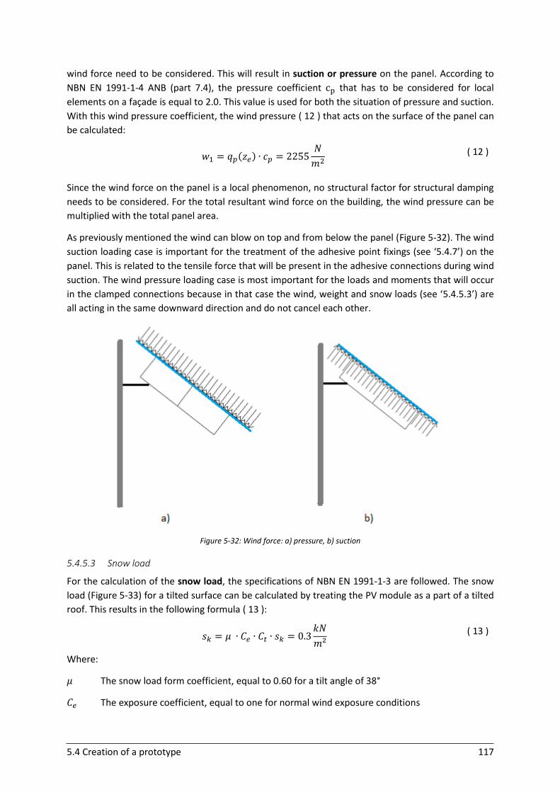
5.4 Creation of a prototype 117
wind force need to be considered. This will result in suction or pressure on the panel. According to
NBN EN 1991-1-4 ANB (part 7.4), the pressure coefficient cp that has to be considered for local
elements on a façade is equal to 2.0. This value is used for both the situation of pressure and suction.
With this wind pressure coefficient, the wind pressure ( 12 ) that acts on the surface of the panel can
be calculated:
𝑤1 = 𝑞𝑝(𝑧𝑒) ∙ 𝑐𝑝 = 2255𝑁
𝑚2
( 12 )
Since the wind force on the panel is a local phenomenon, no structural factor for structural damping
needs to be considered. For the total resultant wind force on the building, the wind pressure can be
multiplied with the total panel area.
As previously mentioned the wind can blow on top and from below the panel (Figure 5-32). The wind
suction loading case is important for the treatment of the adhesive point fixings (see ‘5.4.7’) on the
panel. This is related to the tensile force that will be present in the adhesive connections during wind
suction. The wind pressure loading case is most important for the loads and moments that will occur
in the clamped connections because in that case the wind, weight and snow loads (see ‘5.4.5.3’) are
all acting in the same downward direction and do not cancel each other.
Figure 5-32: Wind force: a) pressure, b) suction
5.4.5.3 Snow load
For the calculation of the snow load, the specifications of NBN EN 1991-1-3 are followed. The snow
load (Figure 5-33) for a tilted surface can be calculated by treating the PV module as a part of a tilted
roof. This results in the following formula ( 13 ):
𝑠𝑘 = 𝜇 ∙ 𝐶𝑒 ∙ 𝐶𝑡 ∙ 𝑠𝑘 = 0.3𝑘𝑁
𝑚² ( 13 )
Where:
𝜇 The snow load form coefficient, equal to 0.60 for a tilt angle of 38°
𝐶𝑒 The exposure coefficient, equal to one for normal wind exposure conditions
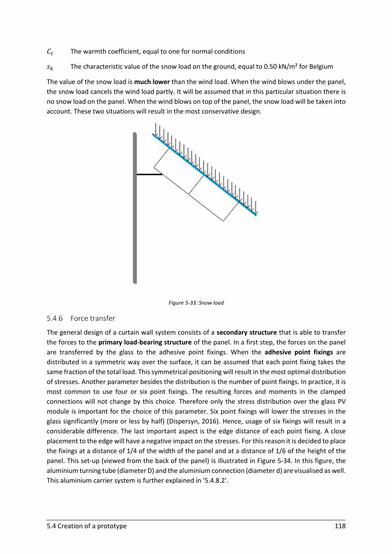
5.4 Creation of a prototype 118
𝐶𝑡 The warmth coefficient, equal to one for normal conditions
𝑠𝑘 The characteristic value of the snow load on the ground, equal to 0.50 kN/m² for Belgium
The value of the snow load is much lower than the wind load. When the wind blows under the panel,
the snow load cancels the wind load partly. It will be assumed that in this particular situation there is
no snow load on the panel. When the wind blows on top of the panel, the snow load will be taken into
account. These two situations will result in the most conservative design.
Figure 5-33: Snow load
5.4.6 Force transfer
The general design of a curtain wall system consists of a secondary structure that is able to transfer
the forces to the primary load-bearing structure of the panel. In a first step, the forces on the panel
are transferred by the glass to the adhesive point fixings. When the adhesive point fixings are
distributed in a symmetric way over the surface, it can be assumed that each point fixing takes the
same fraction of the total load. This symmetrical positioning will result in the most optimal distribution
of stresses. Another parameter besides the distribution is the number of point fixings. In practice, it is
most common to use four or six point fixings. The resulting forces and moments in the clamped
connections will not change by this choice. Therefore only the stress distribution over the glass PV
module is important for the choice of this parameter. Six point fixings will lower the stresses in the
glass significantly (more or less by half) (Dispersyn, 2016). Hence, usage of six fixings will result in a
considerable difference. The last important aspect is the edge distance of each point fixing. A close
placement to the edge will have a negative impact on the stresses. For this reason it is decided to place
the fixings at a distance of 1/4 of the width of the panel and at a distance of 1/6 of the height of the
panel. This set-up (viewed from the back of the panel) is illustrated in Figure 5-34. In this figure, the
aluminium turning tube (diameter D) and the aluminium connection (diameter d) are visualised as well.
This aluminium carrier system is further explained in ‘5.4.8.2’.
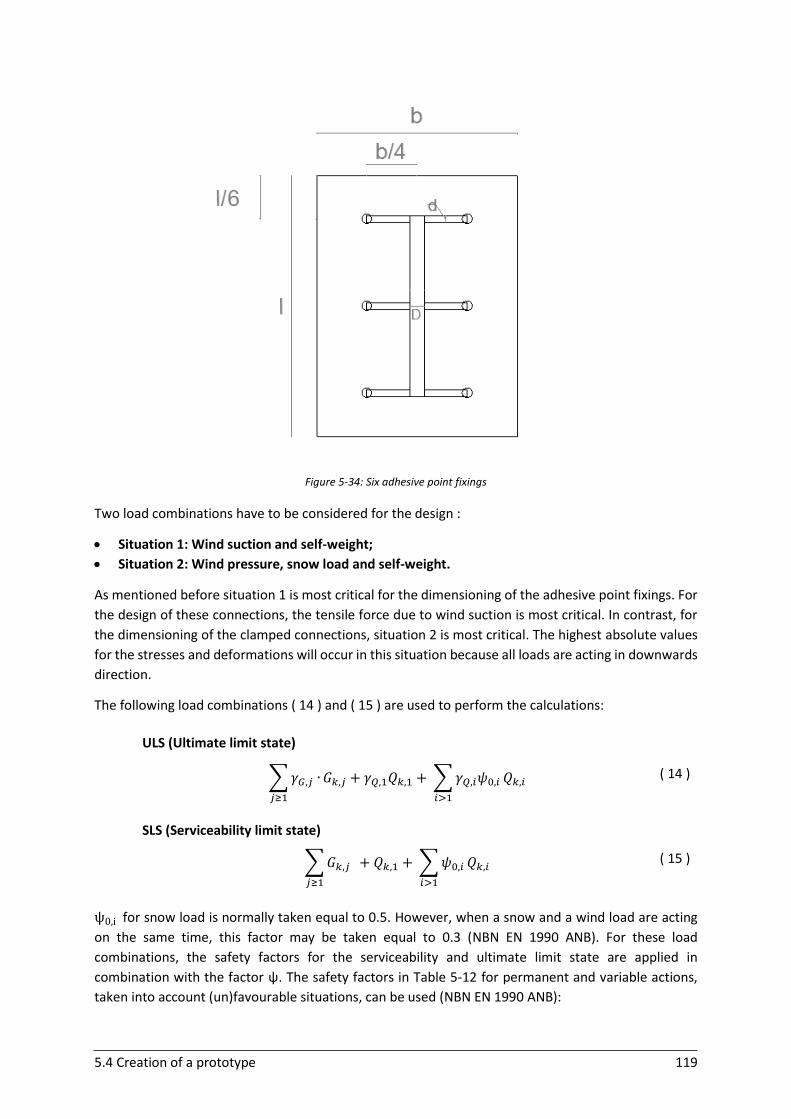
5.4 Creation of a prototype 119
Figure 5-34: Six adhesive point fixings
Two load combinations have to be considered for the design :
Situation 1: Wind suction and self-weight;
Situation 2: Wind pressure, snow load and self-weight.
As mentioned before situation 1 is most critical for the dimensioning of the adhesive point fixings. For
the design of these connections, the tensile force due to wind suction is most critical. In contrast, for
the dimensioning of the clamped connections, situation 2 is most critical. The highest absolute values
for the stresses and deformations will occur in this situation because all loads are acting in downwards
direction.
The following load combinations ( 14 ) and ( 15 ) are used to perform the calculations:
ULS (Ultimate limit state)
∑ 𝛾𝐺,𝑗 ∙
𝑗≥1
𝐺𝑘,𝑗 + 𝛾𝑄,1𝑄𝑘,1 + ∑ 𝛾𝑄,𝑖𝜓0,𝑖 𝑄𝑘,𝑖
𝑖>1
( 14 )
SLS (Serviceability limit state)
∑ 𝐺𝑘,𝑗
𝑗≥1
+ 𝑄𝑘,1 + ∑ 𝜓0,𝑖 𝑄𝑘,𝑖
𝑖>1
( 15 )
ψ0,i for snow load is normally taken equal to 0.5. However, when a snow and a wind load are acting
on the same time, this factor may be taken equal to 0.3 (NBN EN 1990 ANB). For these load
combinations, the safety factors for the serviceability and ultimate limit state are applied in
combination with the factor ψ. The safety factors in Table 5-12 for permanent and variable actions,
taken into account (un)favourable situations, can be used (NBN EN 1990 ANB):

5.4 Creation of a prototype 120
Table 5-12: Safety factors
Safety factor Permanent action ϒG Variable action ϒQ
Favourable 1.00 0
Unfavourable 1.35 1.50
The forces that are taken by the adhesive point fixings are transferred by the aluminium connection to
the aluminium turning tube. This tube will transfer the forces to the first clamped connection (clamp
1 in Figure 5-35) at the free end of the cantilever arm. In this clamped connection a reaction moment
( 16 ), a horizontal reaction force ( 17 ) and a vertical reaction force ( 18 ) will occur. The formulas are
executed for design situation 2 with six point fixings:
𝑀1 = (2𝑃 + (2𝐺 + 2𝑆) ∙ cos(𝛼)) ∙ (𝑏 + 𝑐 − 𝑎)
( 16 )
𝐻1 = 6𝑃 ∙ cos (90° − 𝛼)
( 17 )
𝑉1 = 6𝐺 + 6𝑆 + 6𝑃 ∙ sin (90° − 𝛼) ( 18 )
Where:
P Wind load acting on one adhesive point fixing 𝑃 =𝑝∙𝑏∙𝑙
6
G Self-weight load acting on one adhesive point fixing 𝐺 =𝑔∙𝑏∙𝑙
6
S Snow load acting one adhesive point fixing 𝑆 =𝑠∙𝑏∙𝑙
6
(with b = width of the panel, l = height of the panel, p = wind load/m², g = self-weight/m² and s = snow
load/m²)
Figure 5-35: Design situation

5.4 Creation of a prototype 121
The forces on the first clamped connection are in a next step transferred by the cantilever arm to the
second clamped connection bolted to the wall of the building (Clamp 2 in Figure 5-35). This results in
the following reaction moment ( 19 ) and horizontal ( 20 ) and vertical reaction force ( 21 ) :
𝑀2 = 𝑀1 + 𝑉1 ∙ 𝑥
( 19 )
𝐻2 = 𝐻1
( 20 )
𝑉2 = 𝑉1
( 21 )
With x the distance of the cantilever arm (from the first to the second clamped connection).
5.4.7 Adhesive point fixings
The forces that have to be taken by each adhesive point fixing (six point fixings – design situation 1)
are the following (Ftensile = tensile force ( 22 ), Sshear = shear force ( 23 )):
𝐹𝑡𝑒𝑛𝑠𝑖𝑙𝑒 = 𝑃 − (𝐺 + 𝑆) ∙ cos(𝛼)
( 22 )
𝑆𝑠ℎ𝑒𝑎𝑟 = (𝐺 + 𝑆) ∙ sin (𝛼)
( 23 )
The situation for which the wind blows from below the panel is most critical for the adhesive point
fixings, because the fixings are weakest when loaded in tension. As mentioned before, the snow load
is not considered in this design situation. In this case, each fixing has to be able to withstand (ULS) a
tensile force of 689 N and a shear force of 35 N. Taken into account that the effective depth for stresses
for the laminated plate is equal to 7.1 mm (see ‘5.4.5.1’), it can be concluded that no problems are
expected to withstand these forces with an adhesive point fixing. A connector diameter of 50 mm in
combination with a strong stiff adhesive will be sufficient. The thickness of the adhesive layer is mostly
determined by the manufacturer. For example, for a 3M Scotch-Weld 9323 B/a in shear, a thickness of
0.2 mm is prescribed (Dispersyn, 2016). In case of the second design situation (wind pressure and snow
load) the compression force on the panel is equal to 816 N and the shear force is equal to 65 N. The
suggested adhesive point fixing will be able to withstand these loads.
5.4.8 Stresses and deformations
The stresses in the different materials should be lower than the allowable limits. Stresses need to be
checked in ULS, so formula ( 14 ) has to be used. The design yield strength is equal to : fyd= fyk γM⁄ .
γM is considered equal to 1.0 for steel (NBN EN 1993-1-1), fyk is equal to 235 MPa for the used steel
S235. γM is taken equal to 1.1 for aluminium (NBN EN 1999-1-1), and fyk is taken equal to 270 MPa for
aluminium. The characteristic yield strength of aluminium alloys is usually situated in the range of 200
MPa - 600 MPa.
The normal stresses are equal to ( 24 ):
𝜎 =𝑁
𝐴+
𝑀
𝑊 ( 24 )
And should be limited to ( 25 ):
𝜎 ≤ 𝑓𝑦𝑑 ( 25 )
The shear stresses are equal to ( 26 ):
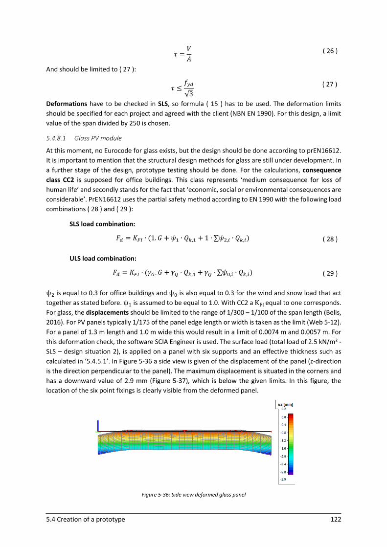
5.4 Creation of a prototype 122
𝜏 =𝑉
𝐴 ( 26 )
And should be limited to ( 27 ):
𝜏 ≤
𝑓𝑦𝑑
√3
( 27 )
Deformations have to be checked in SLS, so formula ( 15 ) has to be used. The deformation limits
should be specified for each project and agreed with the client (NBN EN 1990). For this design, a limit
value of the span divided by 250 is chosen.
5.4.8.1 Glass PV module
At this moment, no Eurocode for glass exists, but the design should be done according to prEN16612.
It is important to mention that the structural design methods for glass are still under development. In
a further stage of the design, prototype testing should be done. For the calculations, consequence
class CC2 is supposed for office buildings. This class represents ‘medium consequence for loss of
human life’ and secondly stands for the fact that ‘economic, social or environmental consequences are
considerable’. PrEN16612 uses the partial safety method according to EN 1990 with the following load
combinations ( 28 ) and ( 29 ):
SLS load combination:
𝐹𝑑 = 𝐾𝐹𝐼 ∙ (1. 𝐺 + 𝜓1 ∙ 𝑄𝑘,1 + 1 ∙ ∑𝜓2,𝑖 ∙ 𝑄𝑘,𝑖) ( 28 )
ULS load combination:
𝐹𝑑 = 𝐾𝐹𝐼 ∙ (𝛾𝐺 . 𝐺 + 𝛾𝑄 ∙ 𝑄𝑘,1 + 𝛾𝑄 ∙ ∑𝜓0,𝑖 ∙ 𝑄𝑘,𝑖) ( 29 )
ψ2 is equal to 0.3 for office buildings and ψ0 is also equal to 0.3 for the wind and snow load that act
together as stated before. ψ1 is assumed to be equal to 1.0. With CC2 a KFI equal to one corresponds.
For glass, the displacements should be limited to the range of 1/300 – 1/100 of the span length (Belis,
2016). For PV panels typically 1/175 of the panel edge length or width is taken as the limit (Web 5-12).
For a panel of 1.3 m length and 1.0 m wide this would result in a limit of 0.0074 m and 0.0057 m. For
this deformation check, the software SCIA Engineer is used. The surface load (total load of 2.5 kN/m² -
SLS – design situation 2), is applied on a panel with six supports and an effective thickness such as
calculated in ‘5.4.5.1’. In Figure 5-36 a side view is given of the displacement of the panel (z-direction
is the direction perpendicular to the panel). The maximum displacement is situated in the corners and
has a downward value of 2.9 mm (Figure 5-37), which is below the given limits. In this figure, the
location of the six point fixings is clearly visible from the deformed panel.
Figure 5-36: Side view deformed glass panel
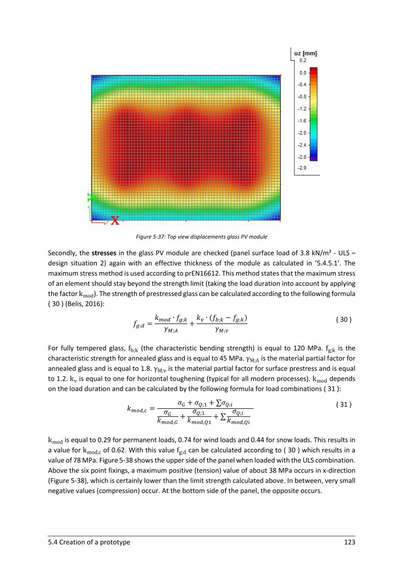
5.4 Creation of a prototype 123
Figure 5-37: Top view displacements glass PV module
Secondly, the stresses in the glass PV module are checked (panel surface load of 3.8 kN/m² - ULS –
design situation 2) again with an effective thickness of the module as calculated in ‘5.4.5.1’. The
maximum stress method is used according to prEN16612. This method states that the maximum stress
of an element should stay beyond the strength limit (taking the load duration into account by applying
the factor kmod). The strength of prestressed glass can be calculated according to the following formula
( 30 ) (Belis, 2016):
𝑓𝑔;𝑑 =
𝑘𝑚𝑜𝑑 ∙ 𝑓𝑔;𝑘
𝛾𝑀;𝐴+
𝑘𝑣 ∙ (𝑓𝑏;𝑘 − 𝑓𝑔;𝑘)
𝛾𝑀;𝑣
( 30 )
For fully tempered glass, fb;k (the characteristic bending strength) is equal to 120 MPa. fg;k is the
characteristic strength for annealed glass and is equal to 45 MPa. γM;A is the material partial factor for
annealed glass and is equal to 1.8. γM;v is the material partial factor for surface prestress and is equal
to 1.2. kv is equal to one for horizontal toughening (typical for all modern processes). kmod depends
on the load duration and can be calculated by the following formula for load combinations ( 31 ):
𝑘𝑚𝑜𝑑,𝑐 =
𝜎𝐺 + 𝜎𝑄;1 + ∑𝜎𝑄;𝑖
𝜎𝐺𝑘𝑚𝑜𝑑,𝐺
+𝜎𝑄;1
𝑘𝑚𝑜𝑑,𝑄1+ ∑
𝜎𝑄;𝑖
𝑘𝑚𝑜𝑑,𝑄𝑖
( 31 )
kmod is equal to 0.29 for permanent loads, 0.74 for wind loads and 0.44 for snow loads. This results in
a value for kmod,c of 0.62. With this value fg;d can be calculated according to ( 30 ) which results in a
value of 78 MPa. Figure 5-38 shows the upper side of the panel when loaded with the ULS combination.
Above the six point fixings, a maximum positive (tension) value of about 38 MPa occurs in x-direction
(Figure 5-38), which is certainly lower than the limit strength calculated above. In between, very small
negative values (compression) occur. At the bottom side of the panel, the opposite occurs.
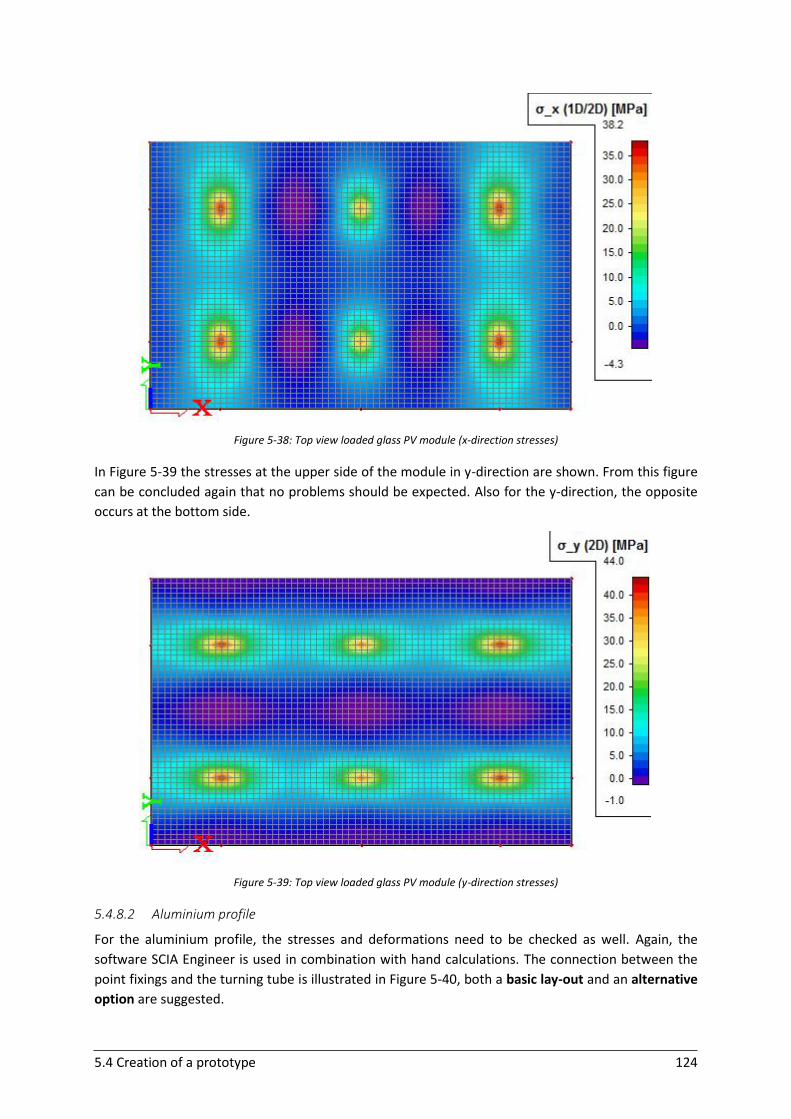
5.4 Creation of a prototype 124
Figure 5-38: Top view loaded glass PV module (x-direction stresses)
In Figure 5-39 the stresses at the upper side of the module in y-direction are shown. From this figure
can be concluded again that no problems should be expected. Also for the y-direction, the opposite
occurs at the bottom side.
Figure 5-39: Top view loaded glass PV module (y-direction stresses)
5.4.8.2 Aluminium profile
For the aluminium profile, the stresses and deformations need to be checked as well. Again, the
software SCIA Engineer is used in combination with hand calculations. The connection between the
point fixings and the turning tube is illustrated in Figure 5-40, both a basic lay-out and an alternative
option are suggested.
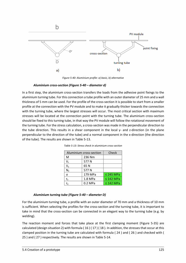
5.4 Creation of a prototype 125
Figure 5-40: Aluminium profile: a) basic, b) alternative
Aluminium cross-section (Figure 5-40 – diameter d)
In a first step, the aluminium cross-section transfers the loads from the adhesive point fixings to the
aluminium turning tube. For this connection a tube profile with an outer diameter of 25 mm and a wall
thickness of 5 mm can be used. For the profile of the cross-section it is possible to start from a smaller
profile at the connection with the PV module and to make it gradually thicker towards the connection
with the turning tube, where the largest stresses will occur. The most critical section with maximum
stresses will be located at the connection point with the turning tube. The aluminium cross-section
should be fixed to this turning tube, in that way the PV module will follow the rotational movement of
the turning tube. For the stress calculation, a cross-section was made in the perpendicular direction to
the tube direction. This results in a shear component in the local y- and z-direction (in the plane
perpendicular to the direction of the tube) and a normal component in the x-direction (the direction
of the tube). The results are shown in Table 5-13.
Table 5-13: Stress check in aluminium cross-section
Aluminium cross-section Check
M 236 Nm
Vz 577 N
Vy 65 N
Nx 577 N
σ 179 MPa ≤ 245 MPa
τz 1.8 MPa ≤ 142 MPa
τy 0.2 MPa ≤ 142 MPa
Aluminium turning tube (Figure 5-40 – diameter D)
For the aluminium turning tube, a profile with an outer diameter of 70 mm and a thickness of 10 mm
is sufficient. When selecting the profiles for the cross-section and the turning tube, it is important to
take in mind that the cross-section can be connected in an elegant way to the turning tube (e.g. by
welding).
The reaction moment and forces that take place at the first clamping moment (Figure 5-35) are
calculated (design situation 2) with formula ( 16 ) ( 17 ) ( 18 ). In addition, the stresses that occur at this
clamped position in the turning tube are calculated with formula ( 24 ) and ( 26 ) and checked with (
25 ) and ( 27 ) respectively. The results are shown in Table 5-14.
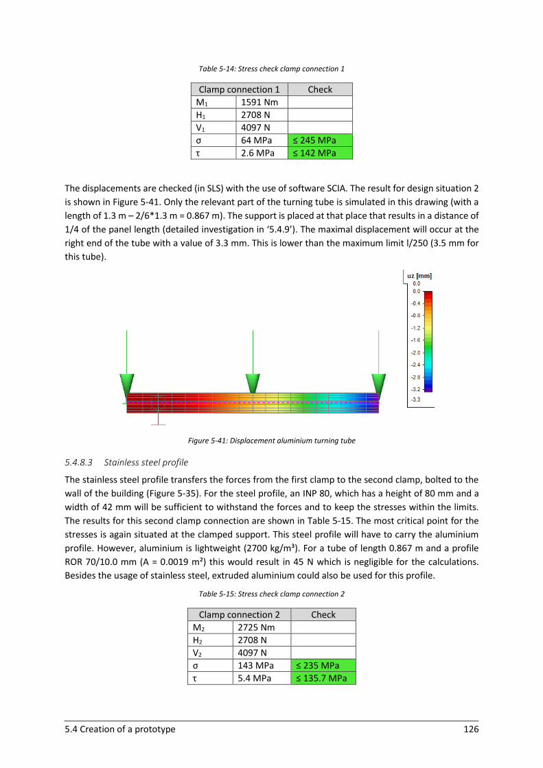
5.4 Creation of a prototype 126
Table 5-14: Stress check clamp connection 1
Clamp connection 1 Check
M1 1591 Nm
H1 2708 N
V1 4097 N
σ 64 MPa ≤ 245 MPa
τ 2.6 MPa ≤ 142 MPa
The displacements are checked (in SLS) with the use of software SCIA. The result for design situation 2
is shown in Figure 5-41. Only the relevant part of the turning tube is simulated in this drawing (with a
length of 1.3 m – 2/6*1.3 m = 0.867 m). The support is placed at that place that results in a distance of
1/4 of the panel length (detailed investigation in ‘5.4.9’). The maximal displacement will occur at the
right end of the tube with a value of 3.3 mm. This is lower than the maximum limit l/250 (3.5 mm for
this tube).
Figure 5-41: Displacement aluminium turning tube
5.4.8.3 Stainless steel profile
The stainless steel profile transfers the forces from the first clamp to the second clamp, bolted to the
wall of the building (Figure 5-35). For the steel profile, an INP 80, which has a height of 80 mm and a
width of 42 mm will be sufficient to withstand the forces and to keep the stresses within the limits.
The results for this second clamp connection are shown in Table 5-15. The most critical point for the
stresses is again situated at the clamped support. This steel profile will have to carry the aluminium
profile. However, aluminium is lightweight (2700 kg/m³). For a tube of length 0.867 m and a profile
ROR 70/10.0 mm (A = 0.0019 m²) this would result in 45 N which is negligible for the calculations.
Besides the usage of stainless steel, extruded aluminium could also be used for this profile.
Table 5-15: Stress check clamp connection 2
Clamp connection 2 Check
M2 2725 Nm
H2 2708 N
V2 4097 N
σ 143 MPa ≤ 235 MPa
τ 5.4 MPa ≤ 135.7 MPa
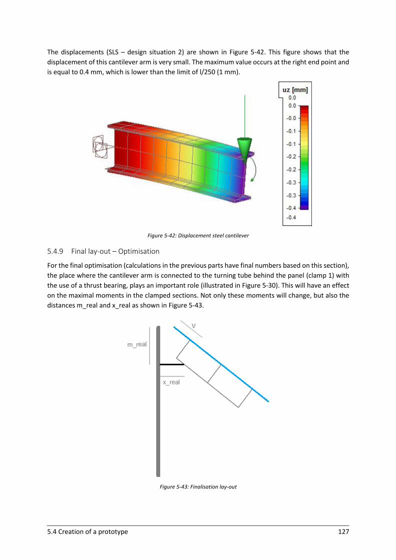
5.4 Creation of a prototype 127
The displacements (SLS – design situation 2) are shown in Figure 5-42. This figure shows that the
displacement of this cantilever arm is very small. The maximum value occurs at the right end point and
is equal to 0.4 mm, which is lower than the limit of l/250 (1 mm).
Figure 5-42: Displacement steel cantilever
5.4.9 Final lay-out – Optimisation
For the final optimisation (calculations in the previous parts have final numbers based on this section),
the place where the cantilever arm is connected to the turning tube behind the panel (clamp 1) with
the use of a thrust bearing, plays an important role (illustrated in Figure 5-30). This will have an effect
on the maximal moments in the clamped sections. Not only these moments will change, but also the
distances m_real and x_real as shown in Figure 5-43.
Figure 5-43: Finalisation lay-out
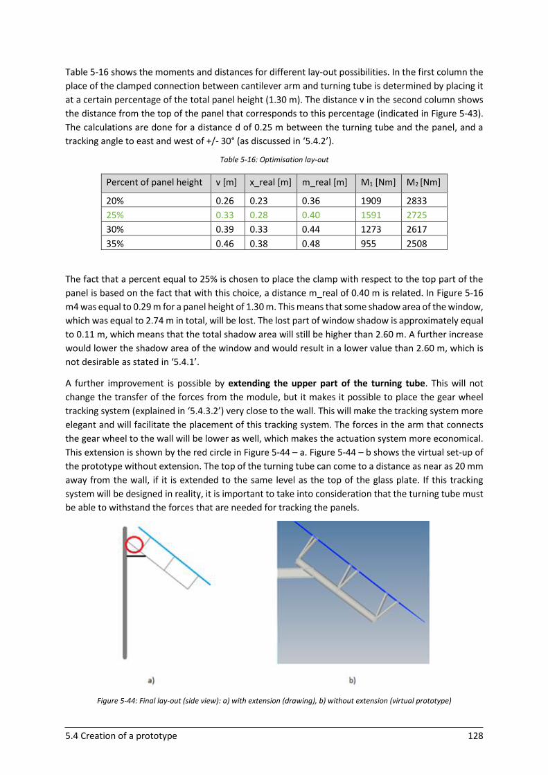
5.4 Creation of a prototype 128
Table 5-16 shows the moments and distances for different lay-out possibilities. In the first column the
place of the clamped connection between cantilever arm and turning tube is determined by placing it
at a certain percentage of the total panel height (1.30 m). The distance v in the second column shows
the distance from the top of the panel that corresponds to this percentage (indicated in Figure 5-43).
The calculations are done for a distance d of 0.25 m between the turning tube and the panel, and a
tracking angle to east and west of +/- 30° (as discussed in ‘5.4.2’).
Table 5-16: Optimisation lay-out
Percent of panel height v [m] x_real [m] m_real [m] M1 [Nm] M2 [Nm]
20% 0.26 0.23 0.36 1909 2833
25% 0.33 0.28 0.40 1591 2725
30% 0.39 0.33 0.44 1273 2617
35% 0.46 0.38 0.48 955 2508
The fact that a percent equal to 25% is chosen to place the clamp with respect to the top part of the
panel is based on the fact that with this choice, a distance m_real of 0.40 m is related. In Figure 5-16
m4 was equal to 0.29 m for a panel height of 1.30 m. This means that some shadow area of the window,
which was equal to 2.74 m in total, will be lost. The lost part of window shadow is approximately equal
to 0.11 m, which means that the total shadow area will still be higher than 2.60 m. A further increase
would lower the shadow area of the window and would result in a lower value than 2.60 m, which is
not desirable as stated in ‘5.4.1’.
A further improvement is possible by extending the upper part of the turning tube. This will not
change the transfer of the forces from the module, but it makes it possible to place the gear wheel
tracking system (explained in ‘5.4.3.2’) very close to the wall. This will make the tracking system more
elegant and will facilitate the placement of this tracking system. The forces in the arm that connects
the gear wheel to the wall will be lower as well, which makes the actuation system more economical.
This extension is shown by the red circle in Figure 5-44 – a. Figure 5-44 – b shows the virtual set-up of
the prototype without extension. The top of the turning tube can come to a distance as near as 20 mm
away from the wall, if it is extended to the same level as the top of the glass plate. If this tracking
system will be designed in reality, it is important to take into consideration that the turning tube must
be able to withstand the forces that are needed for tracking the panels.
Figure 5-44: Final lay-out (side view): a) with extension (drawing), b) without extension (virtual prototype)
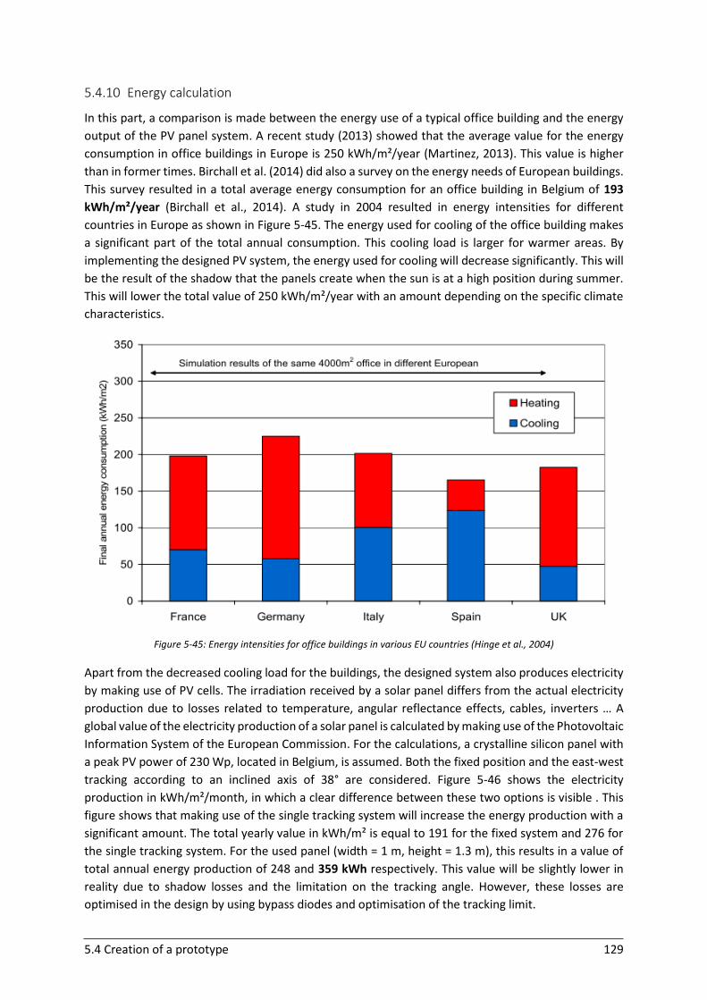
5.4 Creation of a prototype 129
5.4.10 Energy calculation
In this part, a comparison is made between the energy use of a typical office building and the energy
output of the PV panel system. A recent study (2013) showed that the average value for the energy
consumption in office buildings in Europe is 250 kWh/m²/year (Martinez, 2013). This value is higher
than in former times. Birchall et al. (2014) did also a survey on the energy needs of European buildings.
This survey resulted in a total average energy consumption for an office building in Belgium of 193
kWh/m²/year (Birchall et al., 2014). A study in 2004 resulted in energy intensities for different
countries in Europe as shown in Figure 5-45. The energy used for cooling of the office building makes
a significant part of the total annual consumption. This cooling load is larger for warmer areas. By
implementing the designed PV system, the energy used for cooling will decrease significantly. This will
be the result of the shadow that the panels create when the sun is at a high position during summer.
This will lower the total value of 250 kWh/m²/year with an amount depending on the specific climate
characteristics.
Figure 5-45: Energy intensities for office buildings in various EU countries (Hinge et al., 2004)
Apart from the decreased cooling load for the buildings, the designed system also produces electricity
by making use of PV cells. The irradiation received by a solar panel differs from the actual electricity
production due to losses related to temperature, angular reflectance effects, cables, inverters … A
global value of the electricity production of a solar panel is calculated by making use of the Photovoltaic
Information System of the European Commission. For the calculations, a crystalline silicon panel with
a peak PV power of 230 Wp, located in Belgium, is assumed. Both the fixed position and the east-west
tracking according to an inclined axis of 38° are considered. Figure 5-46 shows the electricity
production in kWh/m²/month, in which a clear difference between these two options is visible . This
figure shows that making use of the single tracking system will increase the energy production with a
significant amount. The total yearly value in kWh/m² is equal to 191 for the fixed system and 276 for
the single tracking system. For the used panel (width = 1 m, height = 1.3 m), this results in a value of
total annual energy production of 248 and 359 kWh respectively. This value will be slightly lower in
reality due to shadow losses and the limitation on the tracking angle. However, these losses are
optimised in the design by using bypass diodes and optimisation of the tracking limit.
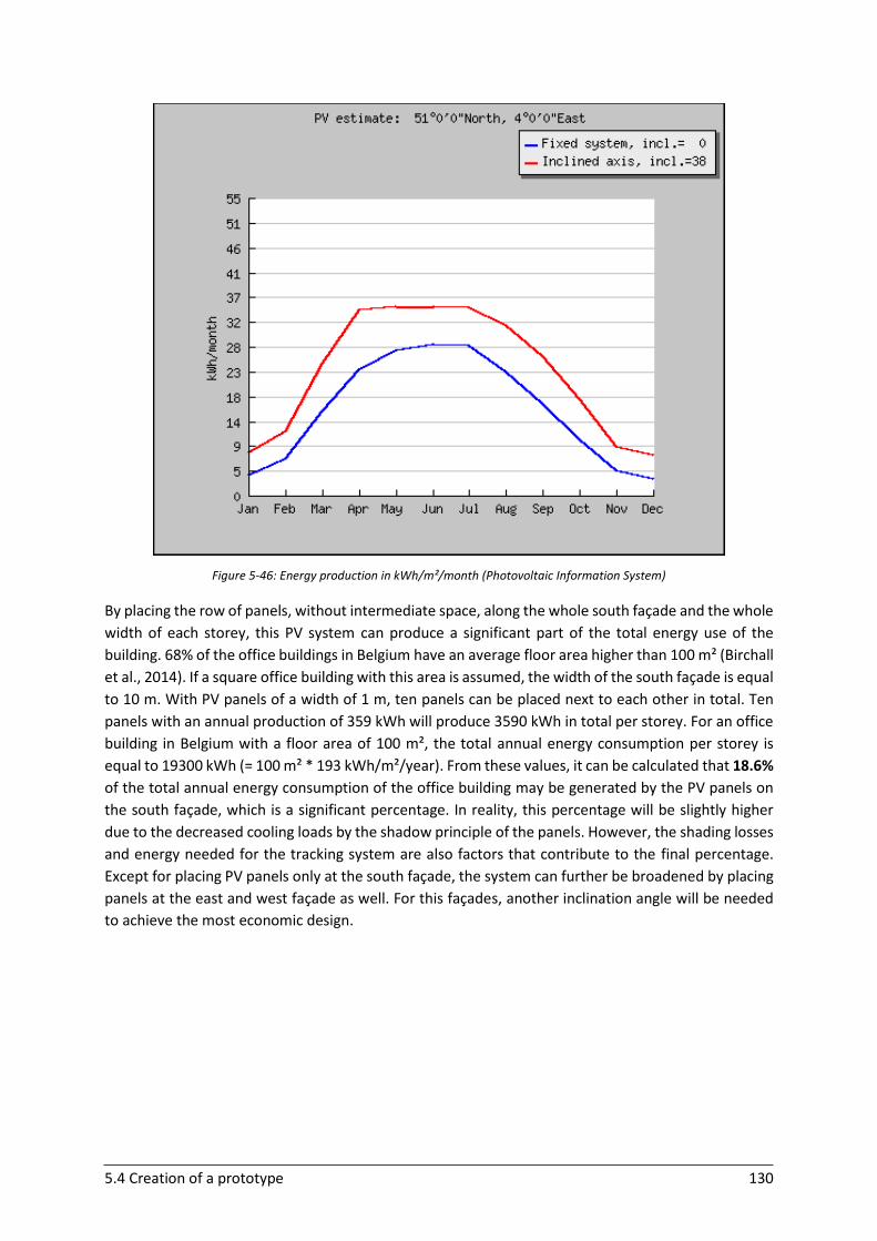
5.4 Creation of a prototype 130
Figure 5-46: Energy production in kWh/m²/month (Photovoltaic Information System)
By placing the row of panels, without intermediate space, along the whole south façade and the whole
width of each storey, this PV system can produce a significant part of the total energy use of the
building. 68% of the office buildings in Belgium have an average floor area higher than 100 m² (Birchall
et al., 2014). If a square office building with this area is assumed, the width of the south façade is equal
to 10 m. With PV panels of a width of 1 m, ten panels can be placed next to each other in total. Ten
panels with an annual production of 359 kWh will produce 3590 kWh in total per storey. For an office
building in Belgium with a floor area of 100 m², the total annual energy consumption per storey is
equal to 19300 kWh (= 100 m² * 193 kWh/m²/year). From these values, it can be calculated that 18.6%
of the total annual energy consumption of the office building may be generated by the PV panels on
the south façade, which is a significant percentage. In reality, this percentage will be slightly higher
due to the decreased cooling loads by the shadow principle of the panels. However, the shading losses
and energy needed for the tracking system are also factors that contribute to the final percentage.
Except for placing PV panels only at the south façade, the system can further be broadened by placing
panels at the east and west façade as well. For this façades, another inclination angle will be needed
to achieve the most economic design.
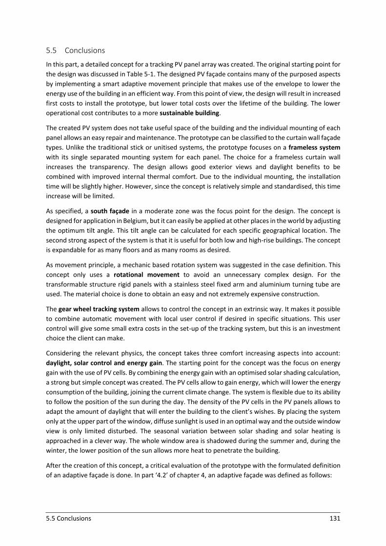
5.5 Conclusions 131
5.5 Conclusions
In this part, a detailed concept for a tracking PV panel array was created. The original starting point for
the design was discussed in Table 5-1. The designed PV façade contains many of the purposed aspects
by implementing a smart adaptive movement principle that makes use of the envelope to lower the
energy use of the building in an efficient way. From this point of view, the design will result in increased
first costs to install the prototype, but lower total costs over the lifetime of the building. The lower
operational cost contributes to a more sustainable building.
The created PV system does not take useful space of the building and the individual mounting of each
panel allows an easy repair and maintenance. The prototype can be classified to the curtain wall façade
types. Unlike the traditional stick or unitised systems, the prototype focuses on a frameless system
with its single separated mounting system for each panel. The choice for a frameless curtain wall
increases the transparency. The design allows good exterior views and daylight benefits to be
combined with improved internal thermal comfort. Due to the individual mounting, the installation
time will be slightly higher. However, since the concept is relatively simple and standardised, this time
increase will be limited.
As specified, a south façade in a moderate zone was the focus point for the design. The concept is
designed for application in Belgium, but it can easily be applied at other places in the world by adjusting
the optimum tilt angle. This tilt angle can be calculated for each specific geographical location. The
second strong aspect of the system is that it is useful for both low and high-rise buildings. The concept
is expandable for as many floors and as many rooms as desired.
As movement principle, a mechanic based rotation system was suggested in the case definition. This
concept only uses a rotational movement to avoid an unnecessary complex design. For the
transformable structure rigid panels with a stainless steel fixed arm and aluminium turning tube are
used. The material choice is done to obtain an easy and not extremely expensive construction.
The gear wheel tracking system allows to control the concept in an extrinsic way. It makes it possible
to combine automatic movement with local user control if desired in specific situations. This user
control will give some small extra costs in the set-up of the tracking system, but this is an investment
choice the client can make.
Considering the relevant physics, the concept takes three comfort increasing aspects into account:
daylight, solar control and energy gain. The starting point for the concept was the focus on energy
gain with the use of PV cells. By combining the energy gain with an optimised solar shading calculation,
a strong but simple concept was created. The PV cells allow to gain energy, which will lower the energy
consumption of the building, joining the current climate change. The system is flexible due to its ability
to follow the position of the sun during the day. The density of the PV cells in the PV panels allows to
adapt the amount of daylight that will enter the building to the client’s wishes. By placing the system
only at the upper part of the window, diffuse sunlight is used in an optimal way and the outside window
view is only limited disturbed. The seasonal variation between solar shading and solar heating is
approached in a clever way. The whole window area is shadowed during the summer and, during the
winter, the lower position of the sun allows more heat to penetrate the building.
After the creation of this concept, a critical evaluation of the prototype with the formulated definition
of an adaptive façade is done. In part ‘4.2’ of chapter 4, an adaptive façade was defined as follows:
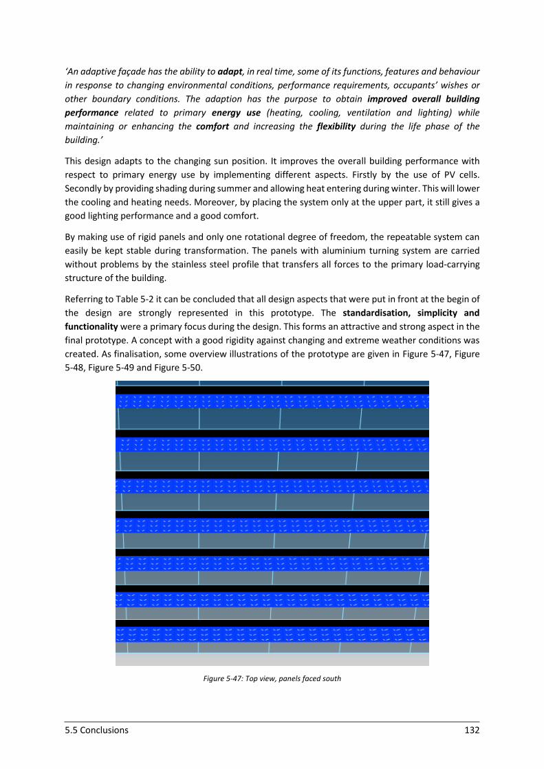
5.5 Conclusions 132
‘An adaptive façade has the ability to adapt, in real time, some of its functions, features and behaviour
in response to changing environmental conditions, performance requirements, occupants’ wishes or
other boundary conditions. The adaption has the purpose to obtain improved overall building
performance related to primary energy use (heating, cooling, ventilation and lighting) while
maintaining or enhancing the comfort and increasing the flexibility during the life phase of the
building.’
This design adapts to the changing sun position. It improves the overall building performance with
respect to primary energy use by implementing different aspects. Firstly by the use of PV cells.
Secondly by providing shading during summer and allowing heat entering during winter. This will lower
the cooling and heating needs. Moreover, by placing the system only at the upper part, it still gives a
good lighting performance and a good comfort.
By making use of rigid panels and only one rotational degree of freedom, the repeatable system can
easily be kept stable during transformation. The panels with aluminium turning system are carried
without problems by the stainless steel profile that transfers all forces to the primary load-carrying
structure of the building.
Referring to Table 5-2 it can be concluded that all design aspects that were put in front at the begin of
the design are strongly represented in this prototype. The standardisation, simplicity and
functionality were a primary focus during the design. This forms an attractive and strong aspect in the
final prototype. A concept with a good rigidity against changing and extreme weather conditions was
created. As finalisation, some overview illustrations of the prototype are given in Figure 5-47, Figure
5-48, Figure 5-49 and Figure 5-50.
Figure 5-47: Top view, panels faced south
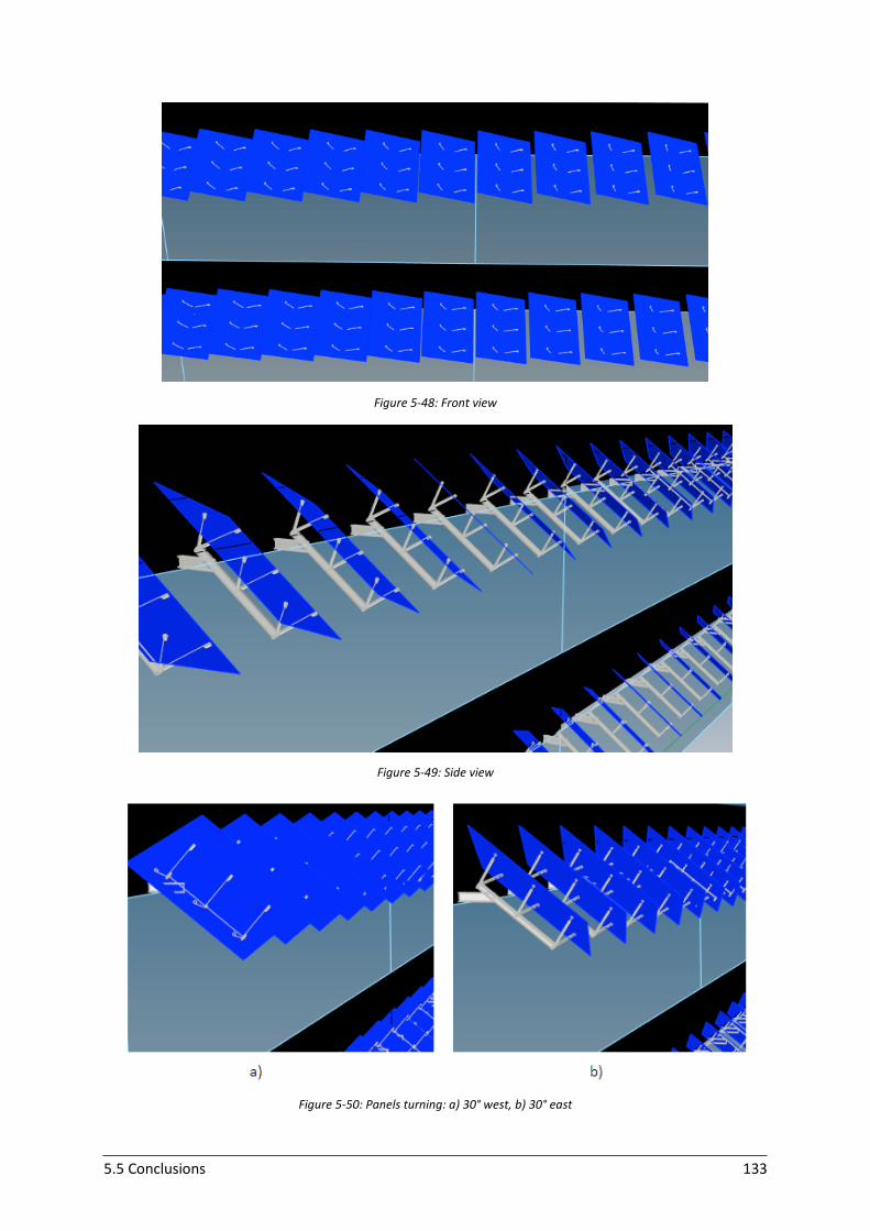
5.5 Conclusions 133
Figure 5-48: Front view
Figure 5-49: Side view
Figure 5-50: Panels turning: a) 30° west, b) 30° east

134

135
PROTOTYPE II:
A perforated Balcony screen
‘Design is about making
things good and fantastic
for the people who use and
encounter them.’
- Matt Baele -
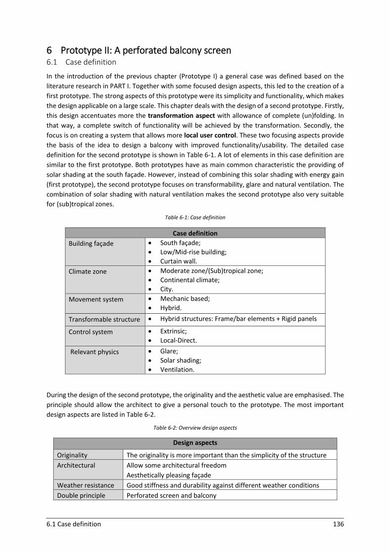
6.1 Case definition 136
6 Prototype II: A perforated balcony screen 6.1 Case definition
In the introduction of the previous chapter (Prototype I) a general case was defined based on the
literature research in PART I. Together with some focused design aspects, this led to the creation of a
first prototype. The strong aspects of this prototype were its simplicity and functionality, which makes
the design applicable on a large scale. This chapter deals with the design of a second prototype. Firstly,
this design accentuates more the transformation aspect with allowance of complete (un)folding. In
that way, a complete switch of functionality will be achieved by the transformation. Secondly, the
focus is on creating a system that allows more local user control. These two focusing aspects provide
the basis of the idea to design a balcony with improved functionality/usability. The detailed case
definition for the second prototype is shown in Table 6-1. A lot of elements in this case definition are
similar to the first prototype. Both prototypes have as main common characteristic the providing of
solar shading at the south façade. However, instead of combining this solar shading with energy gain
(first prototype), the second prototype focuses on transformability, glare and natural ventilation. The
combination of solar shading with natural ventilation makes the second prototype also very suitable
for (sub)tropical zones.
Table 6-1: Case definition
Case definition
Building façade
South façade;
Low/Mid-rise building;
Curtain wall.
Climate zone
Moderate zone/(Sub)tropical zone;
Continental climate;
City.
Movement system
Mechanic based;
Hybrid.
Transformable structure Hybrid structures: Frame/bar elements + Rigid panels
Control system
Extrinsic;
Local-Direct.
Relevant physics
Glare;
Solar shading;
Ventilation.
During the design of the second prototype, the originality and the aesthetic value are emphasised. The
principle should allow the architect to give a personal touch to the prototype. The most important
design aspects are listed in Table 6-2.
Table 6-2: Overview design aspects
Design aspects
Originality The originality is more important than the simplicity of the structure
Architectural Allow some architectural freedom
Aesthetically pleasing façade
Weather resistance Good stiffness and durability against different weather conditions
Double principle Perforated screen and balcony

6.2 Prototype idea 137
6.2 Prototype idea
6.2.1 Double principle
The rich aspect of the second prototype is combining the functionality of a perforated screen with a
balcony. Both have important advantages that contribute to a more sustainable and on the same time
aesthetically pleasing building. The flexibility of the adaptive façade is presented by its multi-ability
aspect, which means that the façade is able to play different roles over time (explained in ‘4.3.6’).
The first function is the folded position of a curtain wall with a perforated screen in front of the glazed
wall of the building. Perforated façade panels offer the opportunity to give the façade of the building
an unique and alternative look. This creates a pleasant effect both on the outside and on the inside
(Figure 6-1).
Figure 6-1: Perforated screen: a) view from outside, b) view from inside (Web 6-01; Web 6-02)
Next to their pleasing appearance, perforated panels have some other important benefits for
residential apartment buildings. Firstly, related to the perforation ratio, the panels will weigh less
than in case of full unperforated panels. This is an advantage for the supporting system that has to
transfer the weight of the panels to the primary structure of the building. A second advantage is the
fact that the panels reduce the wind loading. The perforations allow wind to pass through, which
decreases the wind forces on the structure. Thirdly, perforated panels allow to block partially the sun.
The panels act like sunshades that allow to control the amount of sun that can penetrate the residential
building. This will contribute to a reduced energy use for cooling. The panels have a positive influence
on glare problems and increase the visual comfort of the occupants. The perforations mitigate the
glare from the sun while still allowing the entering of natural daylight to illuminate the interior of the
building. The perforated panels also enhance the privacy for the users, especially for the lowest storeys
of the apartment. Finally, perforated panels have a small influence on the noise. The screen can be
helpful to limit the entering of outside disturbing noise in busy urban areas. All these aspects will
contribute to the design of a low-energy building. If these screens are implemented on a south (or
west/east) façade, larger window to wall ratios are allowed, as the screens provide enough protection
against overheating (Web 6-03).
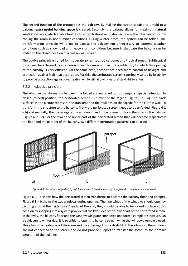
6.2 Prototype idea 138
The second function of the prototype is the balcony. By making the screen capable to unfold to a
balcony, extra useful building space is created. Secondly, the balcony allows for maximum natural
ventilation rates, which enable fresh air to enter. Natural ventilation increases the internal comfort by
cooling the room in hot summer conditions. During winter times, the system can be folded. The
transformation principle will allow to expose the balcony not unnecessary to extreme weather
conditions such as snow load and heavy storm conditions because in that case the balcony can be
folded to the closed position of a curtain wall screen.
The double principle is suited for moderate zones, subtropical zones and tropical zones. (Sub)tropical
zones are characterised by an increased need for maximum natural ventilation, for which the opening
of the balcony is very efficient. On the same time, these zones need more control of daylight and
protection against high heat absorption. For this, the perforated screen is perfectly suited by its ability
to provide protection against overheating while still allowing natural daylight to enter.
6.2.2 Adaptive principle
The adaptive transformation between the folded and unfolded position requires special attention. In
closed (folded) position, the perforated screen is in front of the façade (Figure 6-2 – a). The black
surfaces in the picture represent the transoms and the mullions on the façade for the curtain wall. To
transform the structure to the balcony, firstly the perforated screen needs to be unfolded (Figure 6-2
– b) and secondly, the two wings of the windows need to be opened to form the sides of the balcony
(Figure 6-2 – c). For the lower and upper part of the perforated screen that will become respectively
the floor and the parapet of the balcony, two different perforation patterns can be used.
Figure 6-2: Prototype: a) folded, b) unfolded screen (closed windows), c) unfolded screen (opened windows)
Figure 6-3 – a shows how the perforated screen transforms to become the balcony floor and parapet.
Figure 6-3 – b shows the two windows during opening. The two wings of the windows should open by
pivoting around their sides to 90° each. At the end, they should be able to be locked in place at this
position by snapping into a system provided at the two sides of the lower part of the perforated screen.
In that way, the balcony floor and the window wings are connected and form a complete structure. On
a cold, sunny winter day, it is possible to open the balcony screen while the windows remain closed.
This allows the heating up of the room and the entering of more daylight. In this situation, the windows
are not connected to the screen and do not provide support to transfer the forces to the primary
structure of the building.
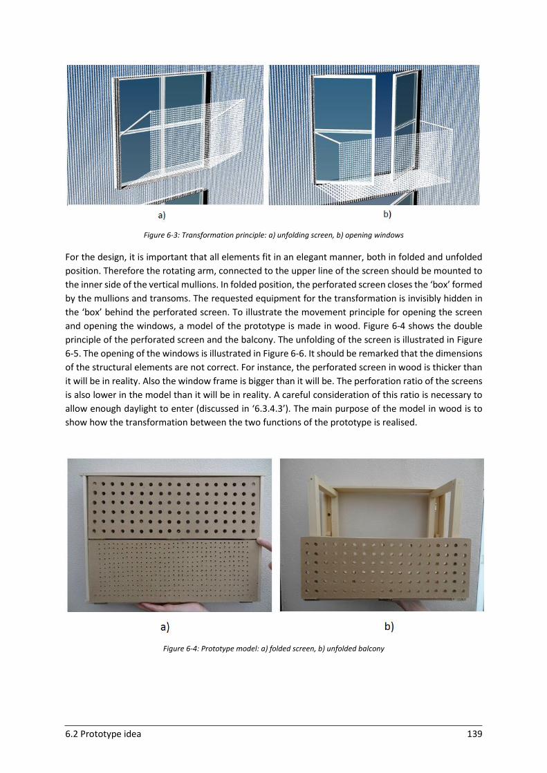
6.2 Prototype idea 139
Figure 6-3: Transformation principle: a) unfolding screen, b) opening windows
For the design, it is important that all elements fit in an elegant manner, both in folded and unfolded
position. Therefore the rotating arm, connected to the upper line of the screen should be mounted to
the inner side of the vertical mullions. In folded position, the perforated screen closes the ‘box’ formed
by the mullions and transoms. The requested equipment for the transformation is invisibly hidden in
the ‘box’ behind the perforated screen. To illustrate the movement principle for opening the screen
and opening the windows, a model of the prototype is made in wood. Figure 6-4 shows the double
principle of the perforated screen and the balcony. The unfolding of the screen is illustrated in Figure
6-5. The opening of the windows is illustrated in Figure 6-6. It should be remarked that the dimensions
of the structural elements are not correct. For instance, the perforated screen in wood is thicker than
it will be in reality. Also the window frame is bigger than it will be. The perforation ratio of the screens
is also lower in the model than it will be in reality. A careful consideration of this ratio is necessary to
allow enough daylight to enter (discussed in ‘6.3.4.3’). The main purpose of the model in wood is to
show how the transformation between the two functions of the prototype is realised.
Figure 6-4: Prototype model: a) folded screen, b) unfolded balcony
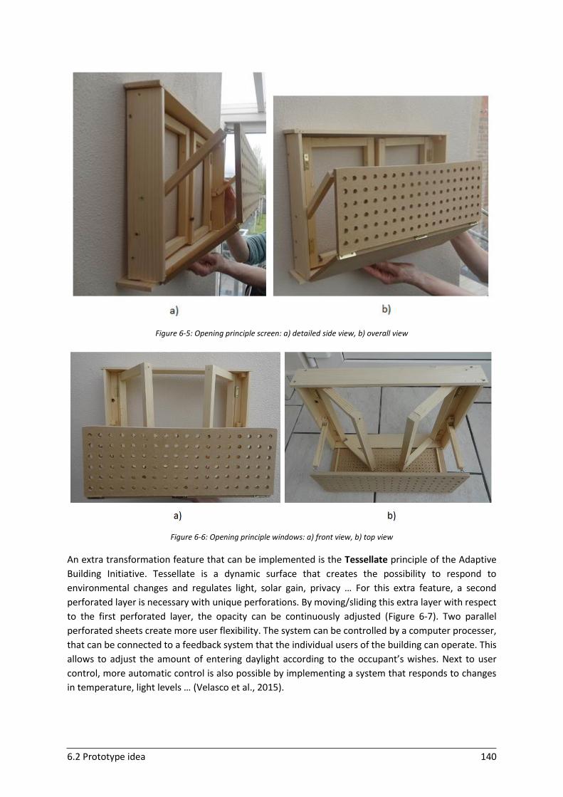
6.2 Prototype idea 140
Figure 6-5: Opening principle screen: a) detailed side view, b) overall view
Figure 6-6: Opening principle windows: a) front view, b) top view
An extra transformation feature that can be implemented is the Tessellate principle of the Adaptive
Building Initiative. Tessellate is a dynamic surface that creates the possibility to respond to
environmental changes and regulates light, solar gain, privacy … For this extra feature, a second
perforated layer is necessary with unique perforations. By moving/sliding this extra layer with respect
to the first perforated layer, the opacity can be continuously adjusted (Figure 6-7). Two parallel
perforated sheets create more user flexibility. The system can be controlled by a computer processer,
that can be connected to a feedback system that the individual users of the building can operate. This
allows to adjust the amount of entering daylight according to the occupant’s wishes. Next to user
control, more automatic control is also possible by implementing a system that responds to changes
in temperature, light levels … (Velasco et al., 2015).
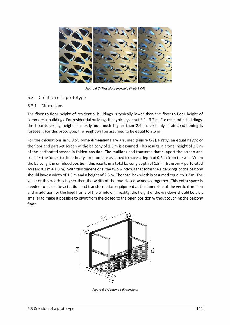
6.3 Creation of a prototype 141
Figure 6-7: Tessellate principle (Web 6-04)
6.3 Creation of a prototype
6.3.1 Dimensions
The floor-to-floor height of residential buildings is typically lower than the floor-to-floor height of
commercial buildings. For residential buildings it’s typically about 3.1 - 3.2 m. For residential buildings,
the floor-to-ceiling height is mostly not much higher than 2.6 m, certainly if air-conditioning is
foreseen. For this prototype, the height will be assumed to be equal to 2.6 m.
For the calculations in ‘6.3.5’, some dimensions are assumed (Figure 6-8). Firstly, an equal height of
the floor and parapet screen of the balcony of 1.3 m is assumed. This results in a total height of 2.6 m
of the perforated screen in folded position. The mullions and transoms that support the screen and
transfer the forces to the primary structure are assumed to have a depth of 0.2 m from the wall. When
the balcony is in unfolded position, this results in a total balcony depth of 1.5 m (transom + perforated
screen: 0.2 m + 1.3 m). With this dimensions, the two windows that form the side wings of the balcony
should have a width of 1.5 m and a height of 2.6 m. The total box width is assumed equal to 3.2 m. The
value of this width is higher than the width of the two closed windows together. This extra space is
needed to place the actuation and transformation equipment at the inner side of the vertical mullion
and in addition for the fixed frame of the window. In reality, the height of the windows should be a bit
smaller to make it possible to pivot from the closed to the open position without touching the balcony
floor.
Figure 6-8: Assumed dimensions
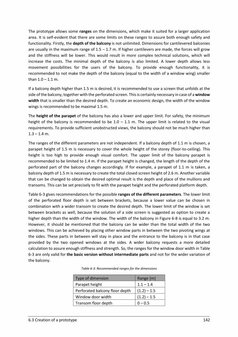
6.3 Creation of a prototype 142
The prototype allows some ranges on the dimensions, which make it suited for a larger application
area. It is self-evident that there are some limits on these ranges to assure both enough safety and
functionality. Firstly, the depth of the balcony is not unlimited. Dimensions for cantilevered balconies
are usually in the maximum range of 1.5 – 1.7 m. If higher cantilevers are made, the forces will grow
and the stiffness will be lower. This would result in more complex technical solutions, which will
increase the costs. The minimal depth of the balcony is also limited. A lower depth allows less
movement possibilities for the users of the balcony. To provide enough functionality, it is
recommended to not make the depth of the balcony (equal to the width of a window wing) smaller
than 1.0 – 1.1 m.
If a balcony depth higher than 1.5 m is desired, it is recommended to use a screen that unfolds at the
side of the balcony, together with the perforated screen. This is certainly necessary in case of a window
width that is smaller than the desired depth. To create an economic design, the width of the window
wings is recommended to be maximal 1.5 m.
The height of the parapet of the balcony has also a lower and upper limit. For safety, the minimum
height of the balcony is recommended to be 1.0 – 1.1 m. The upper limit is related to the visual
requirements. To provide sufficient unobstructed views, the balcony should not be much higher than
1.3 – 1.4 m.
The ranges of the different parameters are not independent. If a balcony depth of 1.1 m is chosen, a
parapet height of 1.5 m is necessary to cover the whole height of the storey (floor-to-ceiling). This
height is too high to provide enough visual comfort. The upper limit of the balcony parapet is
recommended to be limited to 1.4 m. If the parapet height is changed, the length of the depth of the
perforated part of the balcony changes accordingly. If for example, a parapet of 1.1 m is taken, a
balcony depth of 1.5 m is necessary to create the total closed screen height of 2.6 m. Another variable
that can be changed to obtain the desired optimal result is the depth and place of the mullions and
transoms. This can be set precisely to fit with the parapet height and the perforated platform depth.
Table 6-3 gives recommendations for the possible ranges of the different parameters. The lower limit
of the perforated floor depth is set between brackets, because a lower value can be chosen in
combination with a wider transom to create the desired depth. The lower limit of the window is set
between brackets as well, because the solution of a side screen is suggested as option to create a
higher depth than the width of the window. The width of the balcony in Figure 6-8 is equal to 3.2 m.
However, it should be mentioned that the balcony can be wider than the total width of the two
windows. This can be achieved by placing other window parts in between the two pivoting wings at
the sides. These parts in between will stay in place and the entrance to the balcony is in that case
provided by the two opened windows at the sides. A wider balcony requests a more detailed
calculation to assure enough stiffness and strength. So, the ranges for the window door width in Table
6-3 are only valid for the basic version without intermediate parts and not for the wider variation of
the balcony.
Table 6-3: Recommended ranges for the dimensions
Type of dimension Range [m]
Parapet height 1.1 – 1.4
Perforated balcony floor depth (1.2) – 1.5
Window door width (1.2) – 1.5
Transom floor depth 0 – 0.5
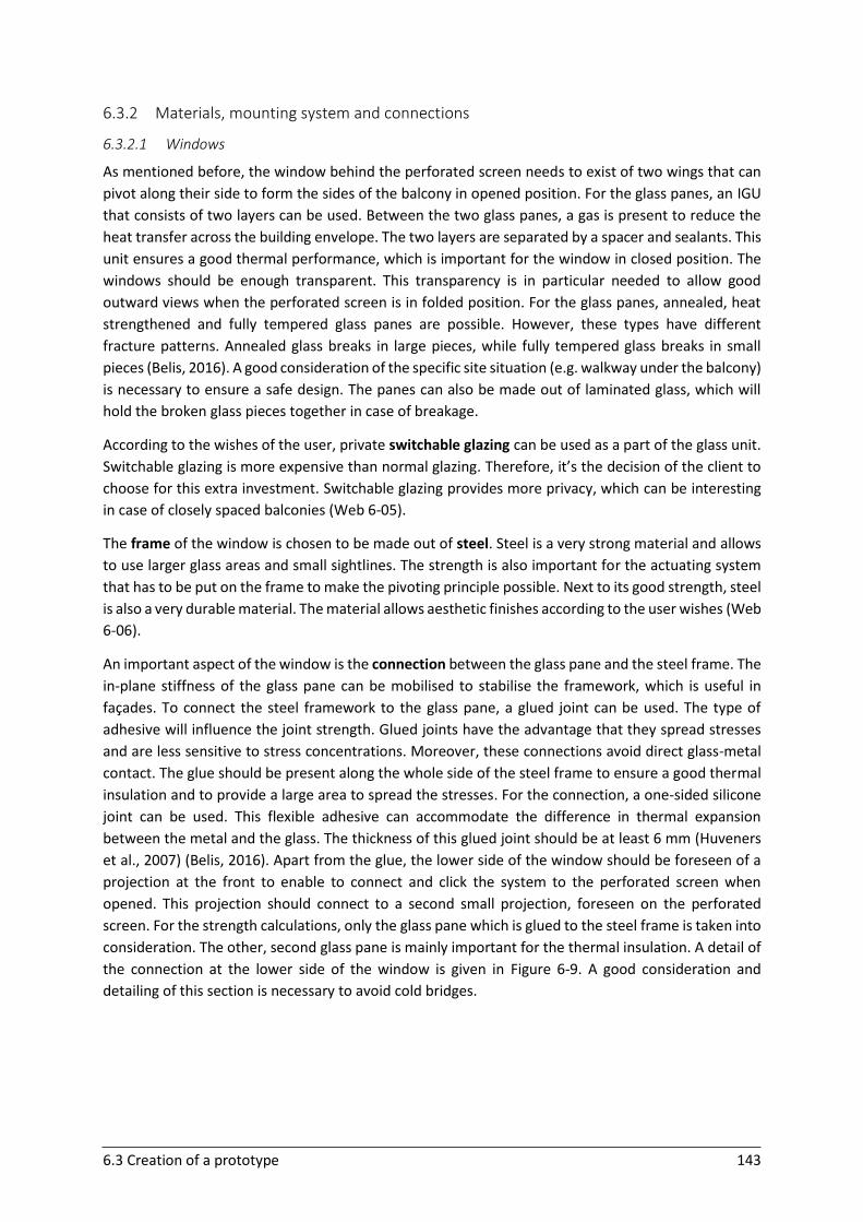
6.3 Creation of a prototype 143
6.3.2 Materials, mounting system and connections
6.3.2.1 Windows
As mentioned before, the window behind the perforated screen needs to exist of two wings that can
pivot along their side to form the sides of the balcony in opened position. For the glass panes, an IGU
that consists of two layers can be used. Between the two glass panes, a gas is present to reduce the
heat transfer across the building envelope. The two layers are separated by a spacer and sealants. This
unit ensures a good thermal performance, which is important for the window in closed position. The
windows should be enough transparent. This transparency is in particular needed to allow good
outward views when the perforated screen is in folded position. For the glass panes, annealed, heat
strengthened and fully tempered glass panes are possible. However, these types have different
fracture patterns. Annealed glass breaks in large pieces, while fully tempered glass breaks in small
pieces (Belis, 2016). A good consideration of the specific site situation (e.g. walkway under the balcony)
is necessary to ensure a safe design. The panes can also be made out of laminated glass, which will
hold the broken glass pieces together in case of breakage.
According to the wishes of the user, private switchable glazing can be used as a part of the glass unit.
Switchable glazing is more expensive than normal glazing. Therefore, it’s the decision of the client to
choose for this extra investment. Switchable glazing provides more privacy, which can be interesting
in case of closely spaced balconies (Web 6-05).
The frame of the window is chosen to be made out of steel. Steel is a very strong material and allows
to use larger glass areas and small sightlines. The strength is also important for the actuating system
that has to be put on the frame to make the pivoting principle possible. Next to its good strength, steel
is also a very durable material. The material allows aesthetic finishes according to the user wishes (Web
6-06).
An important aspect of the window is the connection between the glass pane and the steel frame. The
in-plane stiffness of the glass pane can be mobilised to stabilise the framework, which is useful in
façades. To connect the steel framework to the glass pane, a glued joint can be used. The type of
adhesive will influence the joint strength. Glued joints have the advantage that they spread stresses
and are less sensitive to stress concentrations. Moreover, these connections avoid direct glass-metal
contact. The glue should be present along the whole side of the steel frame to ensure a good thermal
insulation and to provide a large area to spread the stresses. For the connection, a one-sided silicone
joint can be used. This flexible adhesive can accommodate the difference in thermal expansion
between the metal and the glass. The thickness of this glued joint should be at least 6 mm (Huveners
et al., 2007) (Belis, 2016). Apart from the glue, the lower side of the window should be foreseen of a
projection at the front to enable to connect and click the system to the perforated screen when
opened. This projection should connect to a second small projection, foreseen on the perforated
screen. For the strength calculations, only the glass pane which is glued to the steel frame is taken into
consideration. The other, second glass pane is mainly important for the thermal insulation. A detail of
the connection at the lower side of the window is given in Figure 6-9. A good consideration and
detailing of this section is necessary to avoid cold bridges.
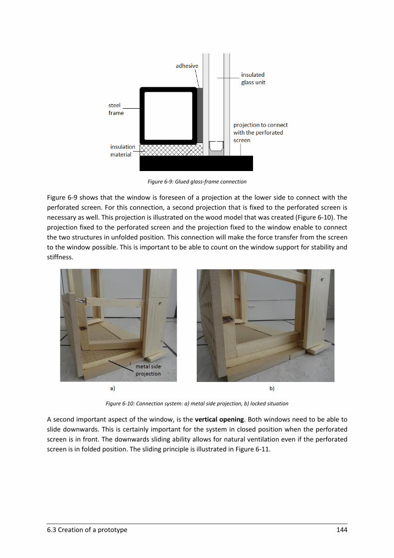
6.3 Creation of a prototype 144
Figure 6-9: Glued glass-frame connection
Figure 6-9 shows that the window is foreseen of a projection at the lower side to connect with the
perforated screen. For this connection, a second projection that is fixed to the perforated screen is
necessary as well. This projection is illustrated on the wood model that was created (Figure 6-10). The
projection fixed to the perforated screen and the projection fixed to the window enable to connect
the two structures in unfolded position. This connection will make the force transfer from the screen
to the window possible. This is important to be able to count on the window support for stability and
stiffness.
Figure 6-10: Connection system: a) metal side projection, b) locked situation
A second important aspect of the window, is the vertical opening. Both windows need to be able to
slide downwards. This is certainly important for the system in closed position when the perforated
screen is in front. The downwards sliding ability allows for natural ventilation even if the perforated
screen is in folded position. The sliding principle is illustrated in Figure 6-11.
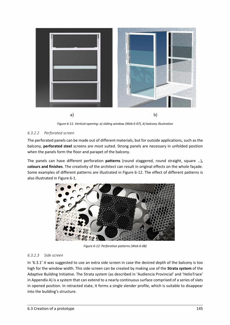
6.3 Creation of a prototype 145
Figure 6-11: Vertical opening: a) sliding window (Web 6-07), b) balcony illustration
6.3.2.2 Perforated screen
The perforated panels can be made out of different materials, but for outside applications, such as the
balcony, perforated steel screens are most suited. Strong panels are necessary in unfolded position
when the panels form the floor and parapet of the balcony.
The panels can have different perforation patterns (round staggered, round straight, square …),
colours and finishes. The creativity of the architect can result in original effects on the whole façade.
Some examples of different patterns are illustrated in Figure 6-12. The effect of different patterns is
also illustrated in Figure 6-1.
Figure 6-12: Perforation patterns (Web 6-08)
6.3.2.3 Side screen
In ‘6.3.1’ it was suggested to use an extra side screen in case the desired depth of the balcony is too
high for the window width. This side screen can be created by making use of the Strata system of the
Adaptive Building Initiative. The Strata system (as described in ‘Audiencia Provincial’ and ‘HelioTrace’
in Appendix A) is a system that can extend to a nearly continuous surface comprised of a series of slats
in opened position. In retracted state, it forms a single slender profile, which is suitable to disappear
into the building’s structure.

6.3 Creation of a prototype 146
6.3.2.4 Mullions and transoms
The structural support for the curtain wall construction is ensured by a framework of linked mullions
and transoms. These vertical and horizontal stiffeners form the façade substructure and are made of
steel. This steel frame will allow to transfer the forces (self-weight, wind load, service load) to the
primary structure of the building. The place where the mullions and transoms are connected to the
wall allows some mounting freedom for the architect. This structural placement was discussed in
‘4.3.4’. The box demarcated by the mullions and transoms can firstly be placed in front of the ordinary
wall. In this case, from outside, the original look of different separated boxes arises. The second
possibility is to widen the concept of a perforated screen over the whole façade and to place the box
behind this complete screen. In this case, the whole box will disappear behind the façade in closed
position. Both options result in different outside views and have another aesthetic effect, which allows
for a wider range of applications. The two design options (both in folded position) are illustrated in
Figure 6-13.
Figure 6-13: Mounting freedom: a) box in front, b) box behind
6.3.2.5 Hinged connections
To make the transformation principle possible, hinges are necessary. Firstly hinges are necessary at
the connection of the rotating part of the window frame to the fixed frame of the window. Secondly,
the two parts of the perforated screen need to be provided with hinges as well. At the connection of
the lowest perforated screen to the horizontal transom, piano hinges can be used (Figure 6-14). This
allows to provide aesthetically clean and elegant lines to create a smooth and streamlined floor for the
balcony.
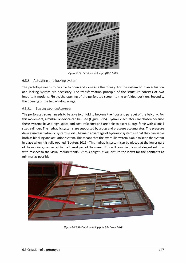
6.3 Creation of a prototype 147
Figure 6-14: Detail piano hinges (Web 6-09)
6.3.3 Actuating and locking system
The prototype needs to be able to open and close in a fluent way. For the system both an actuation
and locking system are necessary. The transformation principle of the structure consists of two
important motions. Firstly, the opening of the perforated screen to the unfolded position. Secondly,
the opening of the two window wings.
6.3.3.1 Balcony floor and parapet
The perforated screen needs to be able to unfold to become the floor and parapet of the balcony. For
this movement, a hydraulic device can be used (Figure 6-15). Hydraulic actuators are chosen because
these systems have a high space and cost efficiency and are able to exert a large force with a small
sized cylinder. The hydraulic systems are supported by a pup and pressure accumulator. The pressure
device used in hydraulic systems is oil. The main advantage of hydraulic systems is that they can serve
both as blocking and actuation system. This means that the hydraulic system is able to keep the system
in place when it is fully opened (Bouten, 2015). This hydraulic system can be placed at the lower part
of the mullions, connected to the lowest part of the screen. This will result in the most elegant solution
with respect to the visual requirements. At this height, it will disturb the views for the habitants as
minimal as possible.
Figure 6-15: Hydraulic opening principle (Web 6-10)
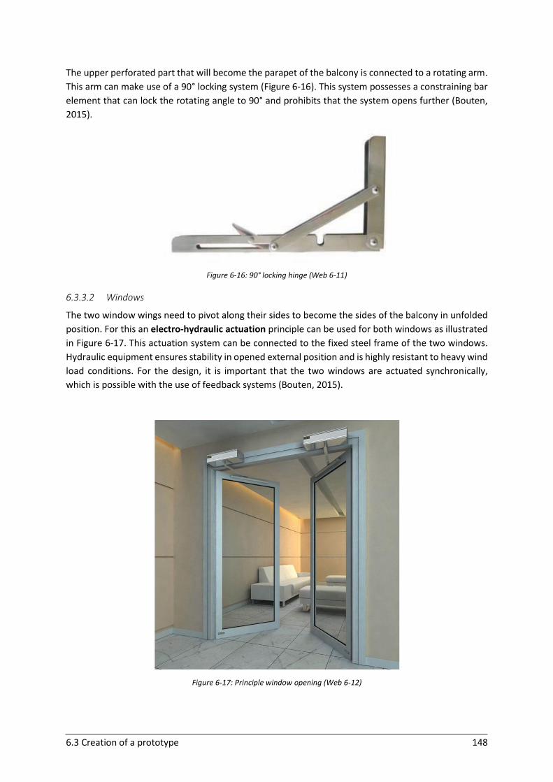
6.3 Creation of a prototype 148
The upper perforated part that will become the parapet of the balcony is connected to a rotating arm.
This arm can make use of a 90° locking system (Figure 6-16). This system possesses a constraining bar
element that can lock the rotating angle to 90° and prohibits that the system opens further (Bouten,
2015).
Figure 6-16: 90° locking hinge (Web 6-11)
6.3.3.2 Windows
The two window wings need to pivot along their sides to become the sides of the balcony in unfolded
position. For this an electro-hydraulic actuation principle can be used for both windows as illustrated
in Figure 6-17. This actuation system can be connected to the fixed steel frame of the two windows.
Hydraulic equipment ensures stability in opened external position and is highly resistant to heavy wind
load conditions. For the design, it is important that the two windows are actuated synchronically,
which is possible with the use of feedback systems (Bouten, 2015).
Figure 6-17: Principle window opening (Web 6-12)
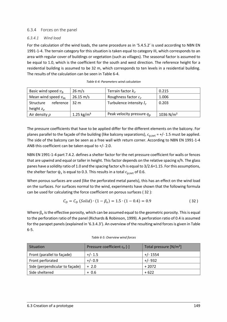
6.3 Creation of a prototype 149
6.3.4 Forces on the panel
6.3.4.1 Wind load
For the calculation of the wind loads, the same procedure as in ‘5.4.5.2’ is used according to NBN EN
1991-1-4. The terrain category for this situation is taken equal to category III, which corresponds to an
area with regular cover of buildings or vegetation (such as villages). The seasonal factor is assumed to
be equal to 1.0, which is the coefficient for the south and west direction. The reference height for a
residential building is assumed to be 32 m, which corresponds to ten levels in a residential building.
The results of the calculation can be seen in Table 6-4.
Table 6-4: Parameters wind calculation
Basic wind speed 𝑣𝑏 26 m/s Terrain factor 𝑘𝑟 0.215
Mean wind speed 𝑣𝑚 26.15 m/s Roughness factor 𝑐𝑟 1.006
Structure reference
height 𝑧𝑒
32 m Turbulence intensity 𝐼𝑟 0.203
Air density 𝜌 1.25 kg/m³ Peak velocity pressure 𝑞𝑝 1036 N/m²
The pressure coefficients that have to be applied differ for the different elements on the balcony. For
planes parallel to the façade of the building (like balcony separations), cp,net = +/- 1.5 must be applied.
The side of the balcony can be seen as a free wall with return corner. According to NBN EN 1991-1-4
ANB this coefficient can be taken equal to +/- 2.0.
NBN EN 1991-1-4 part 7.4.2. defines a shelter factor for the net pressure coefficient for walls or fences
that are upwind and equal or taller in height. This factor depends on the relative spacing x/h. The glass
panes have a solidity ratio of 1.0 and the spacing factor x/h is equal to 3/2.6=1.15. For this assumptions,
the shelter factor ψs is equal to 0.3. This results in a total cp,net of 0.6.
When porous surfaces are used (like the perforated metal panels), this has an effect on the wind load
on the surfaces. For surfaces normal to the wind, experiments have shown that the following formula
can be used for calculating the force coefficient on porous surfaces ( 32 ):
𝐶𝐷 = 𝐶𝐷 (𝑆𝑜𝑙𝑖𝑑) ∙ (1 − 𝛽𝑒) = 1.5 ∙ (1 − 0.4) = 0.9
( 32 )
Where βe is the effective porosity, which can be assumed equal to the geometric porosity. This is equal
to the perforation ratio of the panel (Richards & Robinson, 1999). A perforation ratio of 0.4 is assumed
for the parapet panels (explained in ‘6.3.4.3’). An overview of the resulting wind forces is given in Table
6-5.
Table 6-5: Overview wind forces
Situation Pressure coefficient cp [-] Total pressure [N/m²]
Front (parallel to façade) +/- 1.5 +/- 1554
Front perforated +/- 0.9 +/- 932
Side (perpendicular to façade) + 2.0 + 2072
Side sheltered + 0.6 + 622
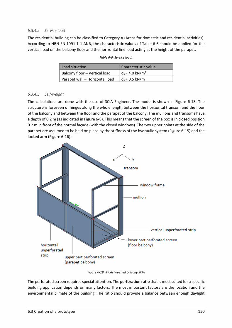
6.3 Creation of a prototype 150
6.3.4.2 Service load
The residential building can be classified to Category A (Areas for domestic and residential activities).
According to NBN EN 1991-1-1 ANB, the characteristic values of Table 6-6 should be applied for the
vertical load on the balcony floor and the horizontal line load acting at the height of the parapet.
Table 6-6: Service loads
Load situation Characteristic value
Balcony floor – Vertical load qk = 4.0 kN/m²
Parapet wall – Horizontal load qk = 0.5 kN/m
6.3.4.3 Self-weight
The calculations are done with the use of SCIA Engineer. The model is shown in Figure 6-18. The
structure is foreseen of hinges along the whole length between the horizontal transom and the floor
of the balcony and between the floor and the parapet of the balcony. The mullions and transoms have
a depth of 0.2 m (as indicated in Figure 6-8). This means that the screen of the box is in closed position
0.2 m in front of the normal façade (with the closed windows). The two upper points at the side of the
parapet are assumed to be held on place by the stiffness of the hydraulic system (Figure 6-15) and the
locked arm (Figure 6-16).
Figure 6-18: Model opened balcony SCIA
The perforated screen requires special attention. The perforation ratio that is most suited for a specific
building application depends on many factors. The most important factors are the location and the
environmental climate of the building. The ratio should provide a balance between enough daylight
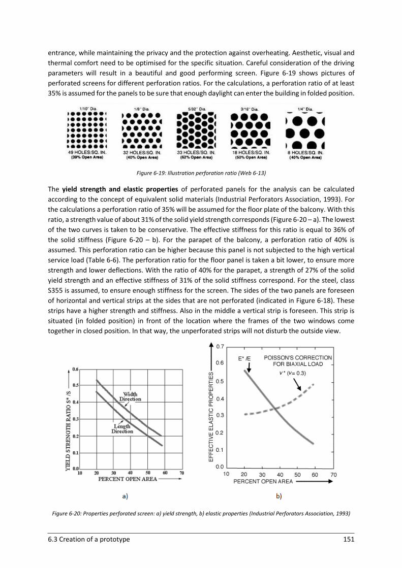
6.3 Creation of a prototype 151
entrance, while maintaining the privacy and the protection against overheating. Aesthetic, visual and
thermal comfort need to be optimised for the specific situation. Careful consideration of the driving
parameters will result in a beautiful and good performing screen. Figure 6-19 shows pictures of
perforated screens for different perforation ratios. For the calculations, a perforation ratio of at least
35% is assumed for the panels to be sure that enough daylight can enter the building in folded position.
Figure 6-19: Illustration perforation ratio (Web 6-13)
The yield strength and elastic properties of perforated panels for the analysis can be calculated
according to the concept of equivalent solid materials (Industrial Perforators Association, 1993). For
the calculations a perforation ratio of 35% will be assumed for the floor plate of the balcony. With this
ratio, a strength value of about 31% of the solid yield strength corresponds (Figure 6-20 – a). The lowest
of the two curves is taken to be conservative. The effective stiffness for this ratio is equal to 36% of
the solid stiffness (Figure 6-20 – b). For the parapet of the balcony, a perforation ratio of 40% is
assumed. This perforation ratio can be higher because this panel is not subjected to the high vertical
service load (Table 6-6). The perforation ratio for the floor panel is taken a bit lower, to ensure more
strength and lower deflections. With the ratio of 40% for the parapet, a strength of 27% of the solid
yield strength and an effective stiffness of 31% of the solid stiffness correspond. For the steel, class
S355 is assumed, to ensure enough stiffness for the screen. The sides of the two panels are foreseen
of horizontal and vertical strips at the sides that are not perforated (indicated in Figure 6-18). These
strips have a higher strength and stiffness. Also in the middle a vertical strip is foreseen. This strip is
situated (in folded position) in front of the location where the frames of the two windows come
together in closed position. In that way, the unperforated strips will not disturb the outside view.
Figure 6-20: Properties perforated screen: a) yield strength, b) elastic properties (Industrial Perforators Association, 1993)
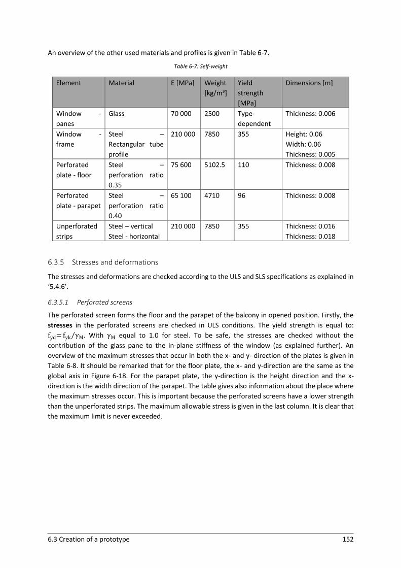
6.3 Creation of a prototype 152
An overview of the other used materials and profiles is given in Table 6-7.
Table 6-7: Self-weight
Element Material E [MPa] Weight
[kg/m³]
Yield
strength
[MPa]
Dimensions [m]
Window -
panes
Glass 70 000 2500 Type-
dependent
Thickness: 0.006
Window -
frame
Steel –
Rectangular tube
profile
210 000 7850 355 Height: 0.06
Width: 0.06
Thickness: 0.005
Perforated
plate - floor
Steel –
perforation ratio
0.35
75 600 5102.5 110 Thickness: 0.008
Perforated
plate - parapet
Steel –
perforation ratio
0.40
65 100 4710 96 Thickness: 0.008
Unperforated
strips
Steel – vertical
Steel - horizontal
210 000 7850 355 Thickness: 0.016
Thickness: 0.018
6.3.5 Stresses and deformations
The stresses and deformations are checked according to the ULS and SLS specifications as explained in
‘5.4.6’.
6.3.5.1 Perforated screens
The perforated screen forms the floor and the parapet of the balcony in opened position. Firstly, the
stresses in the perforated screens are checked in ULS conditions. The yield strength is equal to:
fyd= fyk γM⁄ . With γM equal to 1.0 for steel. To be safe, the stresses are checked without the
contribution of the glass pane to the in-plane stiffness of the window (as explained further). An
overview of the maximum stresses that occur in both the x- and y- direction of the plates is given in
Table 6-8. It should be remarked that for the floor plate, the x- and y-direction are the same as the
global axis in Figure 6-18. For the parapet plate, the y-direction is the height direction and the x-
direction is the width direction of the parapet. The table gives also information about the place where
the maximum stresses occur. This is important because the perforated screens have a lower strength
than the unperforated strips. The maximum allowable stress is given in the last column. It is clear that
the maximum limit is never exceeded.
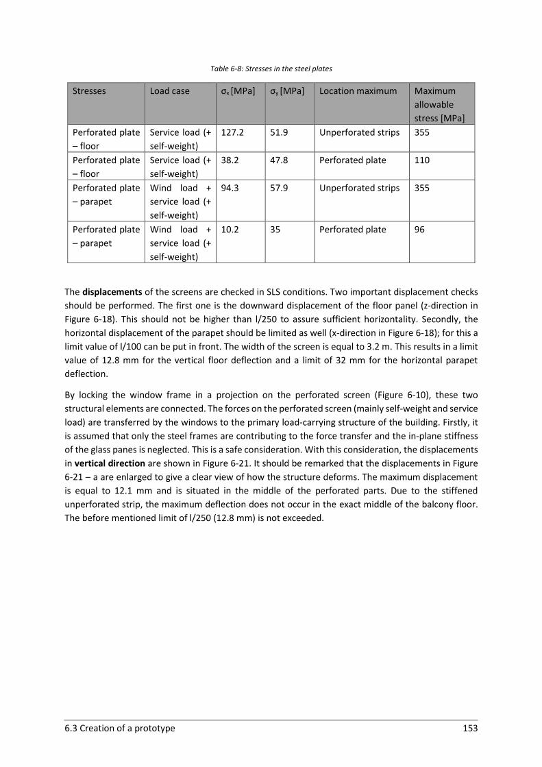
6.3 Creation of a prototype 153
Table 6-8: Stresses in the steel plates
Stresses Load case σx [MPa] σy [MPa] Location maximum Maximum
allowable
stress [MPa]
Perforated plate
– floor
Service load (+
self-weight)
127.2 51.9 Unperforated strips 355
Perforated plate
– floor
Service load (+
self-weight)
38.2 47.8 Perforated plate 110
Perforated plate
– parapet
Wind load +
service load (+
self-weight)
94.3 57.9 Unperforated strips 355
Perforated plate
– parapet
Wind load +
service load (+
self-weight)
10.2 35 Perforated plate 96
The displacements of the screens are checked in SLS conditions. Two important displacement checks
should be performed. The first one is the downward displacement of the floor panel (z-direction in
Figure 6-18). This should not be higher than l/250 to assure sufficient horizontality. Secondly, the
horizontal displacement of the parapet should be limited as well (x-direction in Figure 6-18); for this a
limit value of l/100 can be put in front. The width of the screen is equal to 3.2 m. This results in a limit
value of 12.8 mm for the vertical floor deflection and a limit of 32 mm for the horizontal parapet
deflection.
By locking the window frame in a projection on the perforated screen (Figure 6-10), these two
structural elements are connected. The forces on the perforated screen (mainly self-weight and service
load) are transferred by the windows to the primary load-carrying structure of the building. Firstly, it
is assumed that only the steel frames are contributing to the force transfer and the in-plane stiffness
of the glass panes is neglected. This is a safe consideration. With this consideration, the displacements
in vertical direction are shown in Figure 6-21. It should be remarked that the displacements in Figure
6-21 – a are enlarged to give a clear view of how the structure deforms. The maximum displacement
is equal to 12.1 mm and is situated in the middle of the perforated parts. Due to the stiffened
unperforated strip, the maximum deflection does not occur in the exact middle of the balcony floor.
The before mentioned limit of l/250 (12.8 mm) is not exceeded.

6.3 Creation of a prototype 154
Figure 6-21: Downward displacement: a) side view, b) top view
After this, the in-plane stiffness of the glass pane is taken into account. Only the shear action of the
lowest glass pane of the window is taken into consideration, because the upper part can be slid to an
opened position. The in-plane deformation of the shear wall will decrease due to the contribution of
the glass pane. The stiffness of the used adhesive will influence this decrease. For the calculations, the
modulus of the silicone is assumed to be 1.5 MPa (Web 6-14). In this case, the maximum downward
deflection of the floor of the balcony is equal to a value of 10.8 mm. This value is evidently lower than
the value for the situation in which the glass pane with glued connection is not considered.
To make it possible to unfold the perforated screen on a cold but sunny day, the stability and
displacement in case of an opened balcony without window support is checked. This means that the
window support should only be needed for live loads. The maximum downward deflection in case the
window support is not present and without the service loads is only 1.4 mm and certainly below the
limit of l/250.
With the wind forces on the panel, the maximum horizontal displacement is equal to 21.5 mm, which
is lower than the limit of l/100. Besides the influence of the wind forces, the influence of the horizontal
service load at the upper line of the parapet is taken into account as well. Figure 6-22 shows the
displacement in an enlarged form. By making the horizontal unperforated strip at the top of the
parapet screen thicker, an even lower deflection can be obtained.

6.3 Creation of a prototype 155
Figure 6-22: Horizontal displacement parapet
6.3.5.2 Window (steel frame and glass pane)
The window steel frame is connected to the perforated screen floor of the balcony and transfers the
forces to the primary structure of the building. To create a good view of this force transfer, this part is
modelled separately. The same safety factor γM equal to 1.0 is considered for the steel frame. The
stresses in the glass pane are checked by making use of the maximum stress method. The same
formulas ( 30 ) and ( 31 ) as in ‘5.4.8.1’ are applicable. The only difference is that in this case personnel
loads are present as well, for which a kmod factor of 0.85 should be considered according to
prEN16612. Together with the self-weight, this results in a combined factor kmod,c equal to 0.59, which
results in a value for fg;d of 14.7 MPA for annealed glass, fg;d of 35.5 MPa for heat strengthened glass
and fg;d of 77.2 MPa for tempered glass. In the glass pane, a tension and compression diagonal develop.
Table 6-9 gives an overview of the maximum stresses that occur in the steel frame and glass pane. For
the stresses in the glass pane, the flexibility of the silicone is again taken into account. The tension
stress is considered because this is the most critical stress for glass (both the x- and y-direction of the
pane are verified). The highest stresses occur locally at the edges of the pane. The stresses in the steel
frame are checked for the conservative situation in case the glass pane does not contribute. With the
contribution of the glass pane, these stresses are lower. From the table, it can be concluded that the
maximum limit is never exceeded.
Table 6-9: Stresses in the steel frame and glass pane
Stresses Load case Type Stress
[MPa]
Location Maximum
allowable stress [MPa]
Steel
frame
Service
load (+ self-
weight)
Normal
stress
183 Left side window
(connection to
fixed frame)
355
Steel
frame
Service
load (+ self-
weight)
Shear
stress
68 Left side window
(connection to
fixed frame)
205
Glass
pane
Service
load (+ self-
weight)
Normal
stress
(tension)
5 Left part (edges
glass pane)
14.7 (annealed)
35.5 (heat strengthened)
77.2 (tempered)
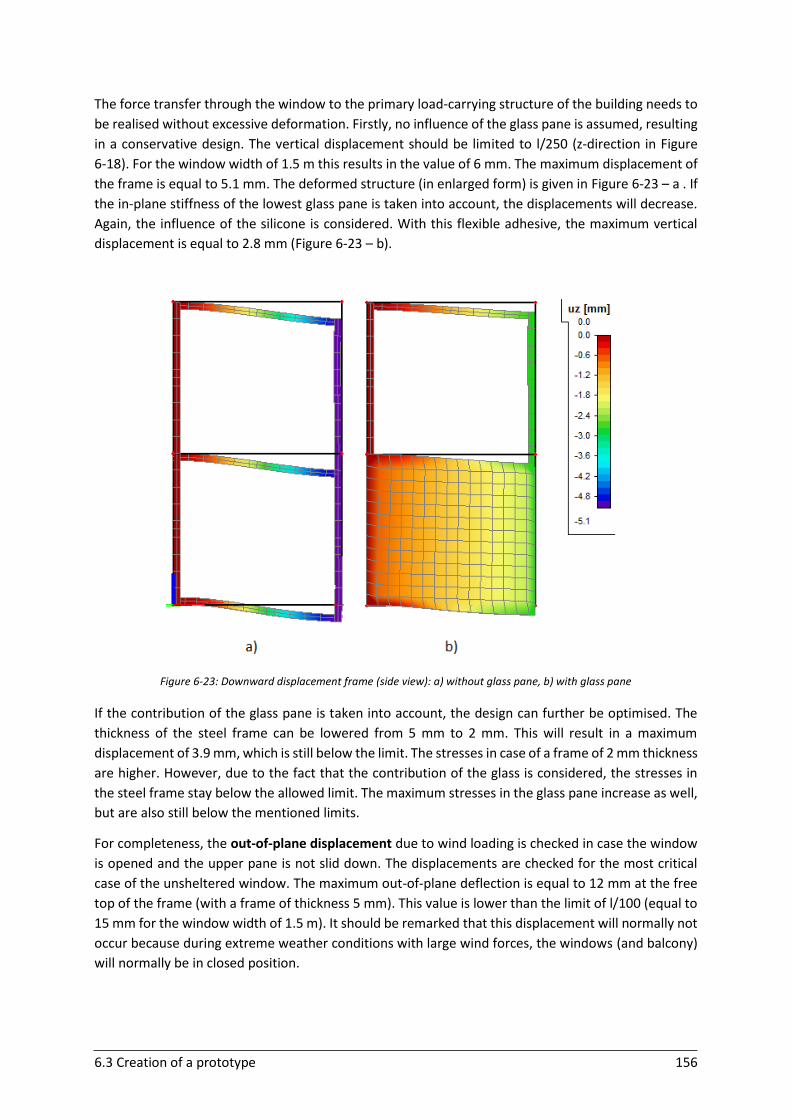
6.3 Creation of a prototype 156
The force transfer through the window to the primary load-carrying structure of the building needs to
be realised without excessive deformation. Firstly, no influence of the glass pane is assumed, resulting
in a conservative design. The vertical displacement should be limited to l/250 (z-direction in Figure
6-18). For the window width of 1.5 m this results in the value of 6 mm. The maximum displacement of
the frame is equal to 5.1 mm. The deformed structure (in enlarged form) is given in Figure 6-23 – a . If
the in-plane stiffness of the lowest glass pane is taken into account, the displacements will decrease.
Again, the influence of the silicone is considered. With this flexible adhesive, the maximum vertical
displacement is equal to 2.8 mm (Figure 6-23 – b).
Figure 6-23: Downward displacement frame (side view): a) without glass pane, b) with glass pane
If the contribution of the glass pane is taken into account, the design can further be optimised. The
thickness of the steel frame can be lowered from 5 mm to 2 mm. This will result in a maximum
displacement of 3.9 mm, which is still below the limit. The stresses in case of a frame of 2 mm thickness
are higher. However, due to the fact that the contribution of the glass is considered, the stresses in
the steel frame stay below the allowed limit. The maximum stresses in the glass pane increase as well,
but are also still below the mentioned limits.
For completeness, the out-of-plane displacement due to wind loading is checked in case the window
is opened and the upper pane is not slid down. The displacements are checked for the most critical
case of the unsheltered window. The maximum out-of-plane deflection is equal to 12 mm at the free
top of the frame (with a frame of thickness 5 mm). This value is lower than the limit of l/100 (equal to
15 mm for the window width of 1.5 m). It should be remarked that this displacement will normally not
occur because during extreme weather conditions with large wind forces, the windows (and balcony)
will normally be in closed position.
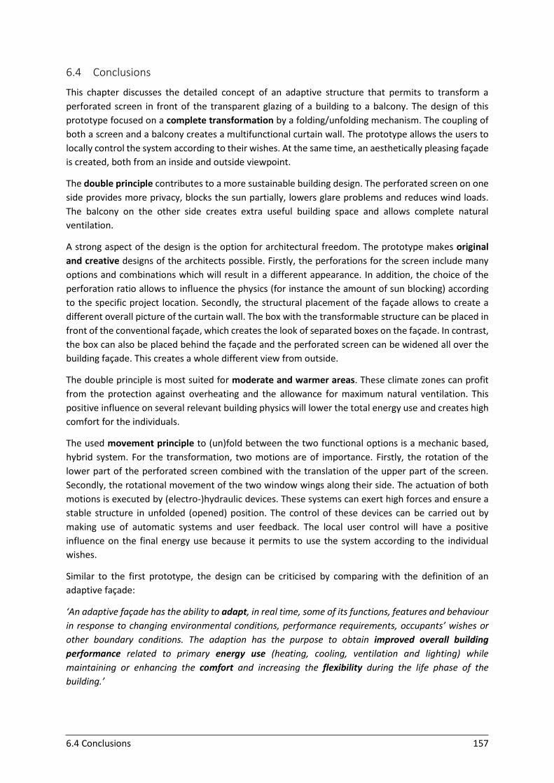
6.4 Conclusions 157
6.4 Conclusions
This chapter discusses the detailed concept of an adaptive structure that permits to transform a
perforated screen in front of the transparent glazing of a building to a balcony. The design of this
prototype focused on a complete transformation by a folding/unfolding mechanism. The coupling of
both a screen and a balcony creates a multifunctional curtain wall. The prototype allows the users to
locally control the system according to their wishes. At the same time, an aesthetically pleasing façade
is created, both from an inside and outside viewpoint.
The double principle contributes to a more sustainable building design. The perforated screen on one
side provides more privacy, blocks the sun partially, lowers glare problems and reduces wind loads.
The balcony on the other side creates extra useful building space and allows complete natural
ventilation.
A strong aspect of the design is the option for architectural freedom. The prototype makes original
and creative designs of the architects possible. Firstly, the perforations for the screen include many
options and combinations which will result in a different appearance. In addition, the choice of the
perforation ratio allows to influence the physics (for instance the amount of sun blocking) according
to the specific project location. Secondly, the structural placement of the façade allows to create a
different overall picture of the curtain wall. The box with the transformable structure can be placed in
front of the conventional façade, which creates the look of separated boxes on the façade. In contrast,
the box can also be placed behind the façade and the perforated screen can be widened all over the
building façade. This creates a whole different view from outside.
The double principle is most suited for moderate and warmer areas. These climate zones can profit
from the protection against overheating and the allowance for maximum natural ventilation. This
positive influence on several relevant building physics will lower the total energy use and creates high
comfort for the individuals.
The used movement principle to (un)fold between the two functional options is a mechanic based,
hybrid system. For the transformation, two motions are of importance. Firstly, the rotation of the
lower part of the perforated screen combined with the translation of the upper part of the screen.
Secondly, the rotational movement of the two window wings along their side. The actuation of both
motions is executed by (electro-)hydraulic devices. These systems can exert high forces and ensure a
stable structure in unfolded (opened) position. The control of these devices can be carried out by
making use of automatic systems and user feedback. The local user control will have a positive
influence on the final energy use because it permits to use the system according to the individual
wishes.
Similar to the first prototype, the design can be criticised by comparing with the definition of an
adaptive façade:
‘An adaptive façade has the ability to adapt, in real time, some of its functions, features and behaviour
in response to changing environmental conditions, performance requirements, occupants’ wishes or
other boundary conditions. The adaption has the purpose to obtain improved overall building
performance related to primary energy use (heating, cooling, ventilation and lighting) while
maintaining or enhancing the comfort and increasing the flexibility during the life phase of the
building.’
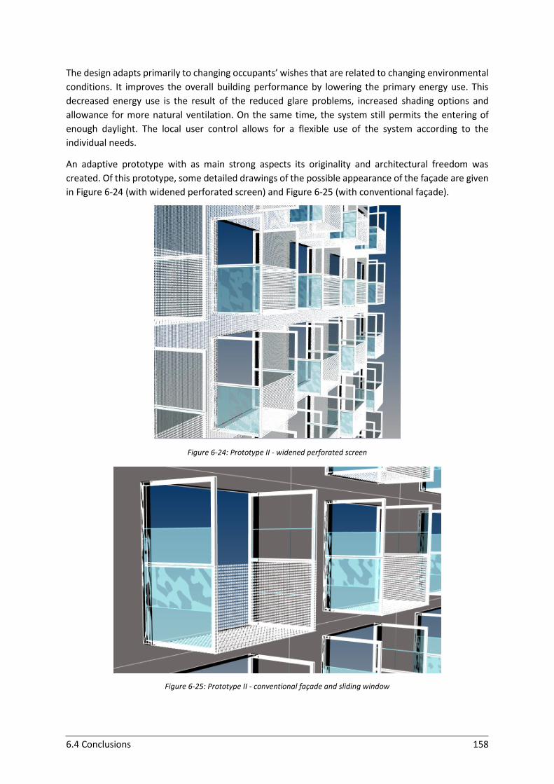
6.4 Conclusions 158
The design adapts primarily to changing occupants’ wishes that are related to changing environmental
conditions. It improves the overall building performance by lowering the primary energy use. This
decreased energy use is the result of the reduced glare problems, increased shading options and
allowance for more natural ventilation. On the same time, the system still permits the entering of
enough daylight. The local user control allows for a flexible use of the system according to the
individual needs.
An adaptive prototype with as main strong aspects its originality and architectural freedom was
created. Of this prototype, some detailed drawings of the possible appearance of the façade are given
in Figure 6-24 (with widened perforated screen) and Figure 6-25 (with conventional façade).
Figure 6-24: Prototype II - widened perforated screen
Figure 6-25: Prototype II - conventional façade and sliding window
159
7 General conclusion
The main objective of this thesis was to study the contribution of the building’s façade in the design of
low-energy buildings. The increased interest and need to improve the energy impact is triggered by
the current changing climate. Structural adaptive façades use flexibility to adapt and react to changing
conditions. This with the purpose to lower the total life cycle costs and environmental impact of
buildings while maintaining high comfort for their habitants. By implementing the fourth dimension of
time, the façade becomes a dynamic playground to optimise between energy balances and occupants’
wishes.
A good understanding and investigation of the possibilities of transformable structures and building
façades allowed to obtain a clear view on the type of structures and advanced façades that are best
suited to design structural adaptive façades in an economic and aesthetic way. Secondly, a careful
study of realisations and prototypes of adaptive façades resulted in useful knowledge and
comprehension of innovative initiatives, shortcomings and potential improvements. A large part of
these examples are still quite complex and building-specific. Further optimisation is necessary to
facilitate and improve future designs to make them more economical and applicable on a larger scale.
The research provides a better understanding of the working principles of structural adaptive façades.
It is obvious that an aesthetical adaptive façade belongs to a multidisciplinary design culture that
requires the gathered knowledge of different experts.
Apart from the detailed examination of the state of the art of the transformable structures, building
façades and adaptive façades, this thesis zoomed in on the effective design of two prototypes. These
prototypes concentrate on some specific building and design aspects. The optimisation of adaptive
façades to perform well on several building physics and to maintain a high comfort is a complex
challenge. Therefore, careful consideration of the focused aspects is of main importance for the end
result. In this perspective, the two prototypes differ significantly. The first prototype puts the
emphasise on energy gain and solar shading, while the second one mainly concentrates on glare, solar
shading and ventilation. Besides the building physics, the movement and control of the two adaptive
prototypes are completely different as well. The first prototype is optimised for a daily, global, rotating
motion. The second prototype allows for complete transformation based on hybrid movement
combined with individual user control. The first prototype emphasised simplicity and functionality,
while for the second one the aesthetical effect and architectural freedom were of main importance.
Both designs have a broad range of application possibilities and demand detailed optimisation for
specific geographical and environmental conditions.
The two developed prototypes offered the occasion to experience that every design differs completely
and has its own specific challenges that ask for an elegant solution. A careful, scientifically based
analysis along with creative, gradually developing concepts and meticulous calculations, that is what
makes civil engineering an ever-interesting domain!

160
8 Future perspectives
A lot of investigation about structural adaptive façades is already performed which has led to beautiful
and functional applications. However, many improvement possibilities and developing opportunities
still exist. This thesis dealt with the detailed design of two potential prototypes, focusing on specific
domains of building physics. However, the architectural subdomain of structural adaptive façades is
far from saturated. By considering other aspects, endless opportunities are present to create new
promising designs.
The two prototypes possess the capacity to be applied in sustainable buildings. To achieve a good
performance of these prototypes, application-specific and context-dependent calculations are
necessary to further optimise their design. A good simulation of local connections is necessary to avoid
local failure and to create durable prototypes. Further investigation about the required forces for the
actuators and their influence on the structural elements is necessary. Apart from this, a careful
consideration of the combination of automatic and local control is strongly advised to improve the
overall performance.
Once the prototypes are implemented into building façades, detailed monitoring and evaluation of the
performance are highly suited to further improve the designs. These evaluation and simulation tools
are helpful because the development of adaptive concepts is very challenging and often leads to too
conservative decisions. In addition, these tools are not only effective for new designs but certainly also
for existing adaptive façades. Experimental projects with innovative and creative ideas are often an
incentive for the evolution of the mainstream.
161
APPENDIX A. Case Studies
162
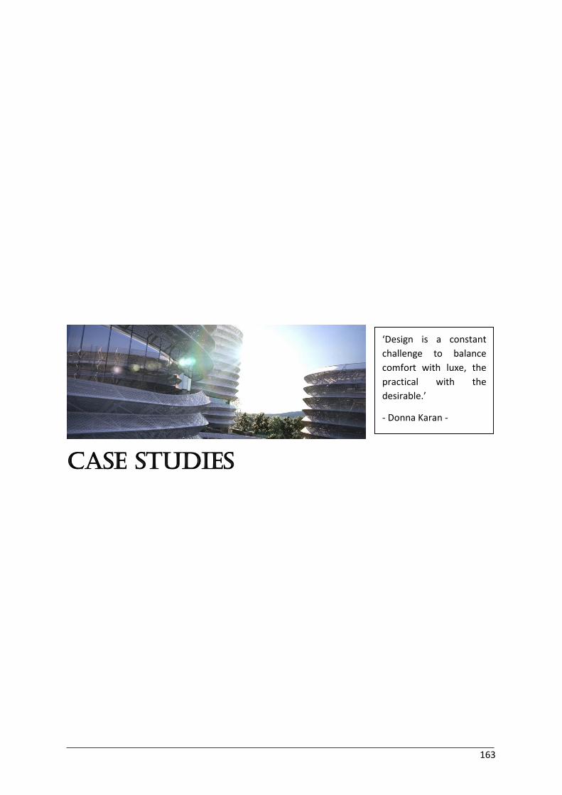
163
Case Studies
‘Design is a constant
challenge to balance
comfort with luxe, the
practical with the
desirable.’
- Donna Karan -
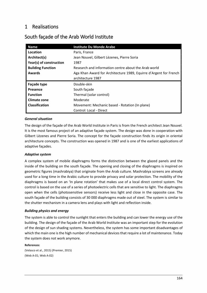
164
1 Realisations
South façade of the Arab World Institute
Name Institute Du Monde Arabe
Location Paris, France
Architect(s) Jean Nouvel, Gilbert Lèzenes, Pierre Soria
Year(s) of construction 1987
Building Function Research and information centre about the Arab world
Awards Aga Khan Award for Architecture 1989, Equirre d’Argent for French
architecture 1987
Façade type Double-skin
Presence South façade
Function
Climate zone
Classification
Thermal (solar control)
Moderate
Movement: Mechanic based - Rotation (In plane)
Control: Local - Direct General situation
The design of the façade of the Arab World Institute in Paris is from the French architect Jean Nouvel.
It is the most famous project of an adaptive façade system. The design was done in cooperation with
Gilbert Lèzenes and Pierre Soria. The concept for the façade construction finds its origin in oriental
architecture concepts. The construction was opened in 1987 and is one of the earliest applications of
adaptive façades.
Adaptive system
A complex system of mobile diaphragms forms the distinction between the glazed panels and the
inside of the building on the south façade. The opening and closing of the diaphragms is inspired on
geometric figures (mashrabiya) that originate from the Arab culture. Mashrabiya screens are already
used for a long time in the Arabic culture to provide privacy and solar protection. The mobility of the
diaphragms is based on an ‘In plane rotation’ that makes use of a local direct control system. The
control is based on the use of a series of photoelectric cells that are sensitive to light. The diaphragms
open when the cells (photosensitive sensors) receive less light and close in the opposite case. The
south façade of the building consists of 30 000 diaphragms made out of steel. The system is similar to
the shutter mechanism in a camera lens and plays with light and reflection inside.
Building physics and energy
The system is able to control the sunlight that enters the building and can lower the energy use of the
building. The design of the façade of the Arab World Institute was an important step for the evolution
of the design of sun shading systems. Nevertheless, the system has some important disadvantages of
which the main one is the high number of mechanical devices that require a lot of maintenance. Today
the system does not work anymore.
References:
(Velasco et al., 2015) (Premier, 2015)
(Web A-01; Web A-02)
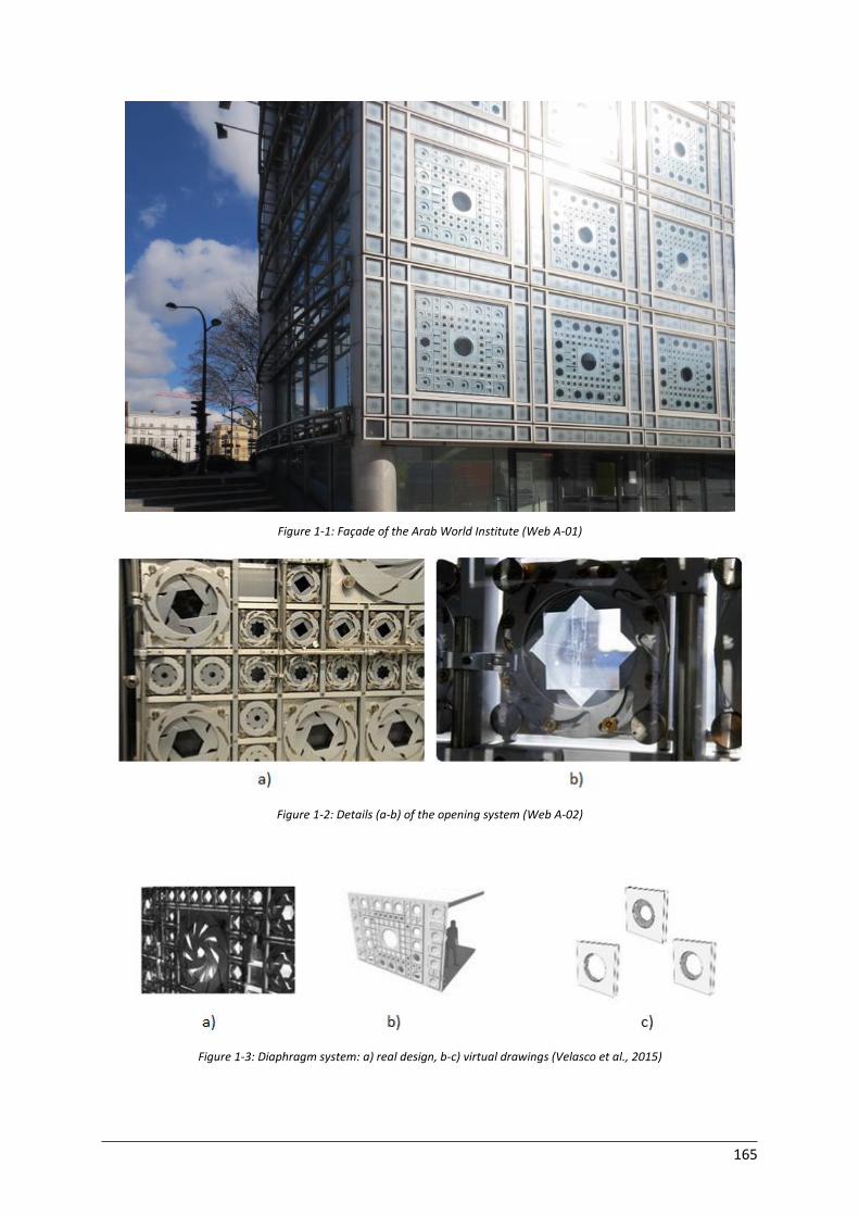
165
Figure 1-1: Façade of the Arab World Institute (Web A-01)
Figure 1-2: Details (a-b) of the opening system (Web A-02)
Figure 1-3: Diaphragm system: a) real design, b-c) virtual drawings (Velasco et al., 2015)
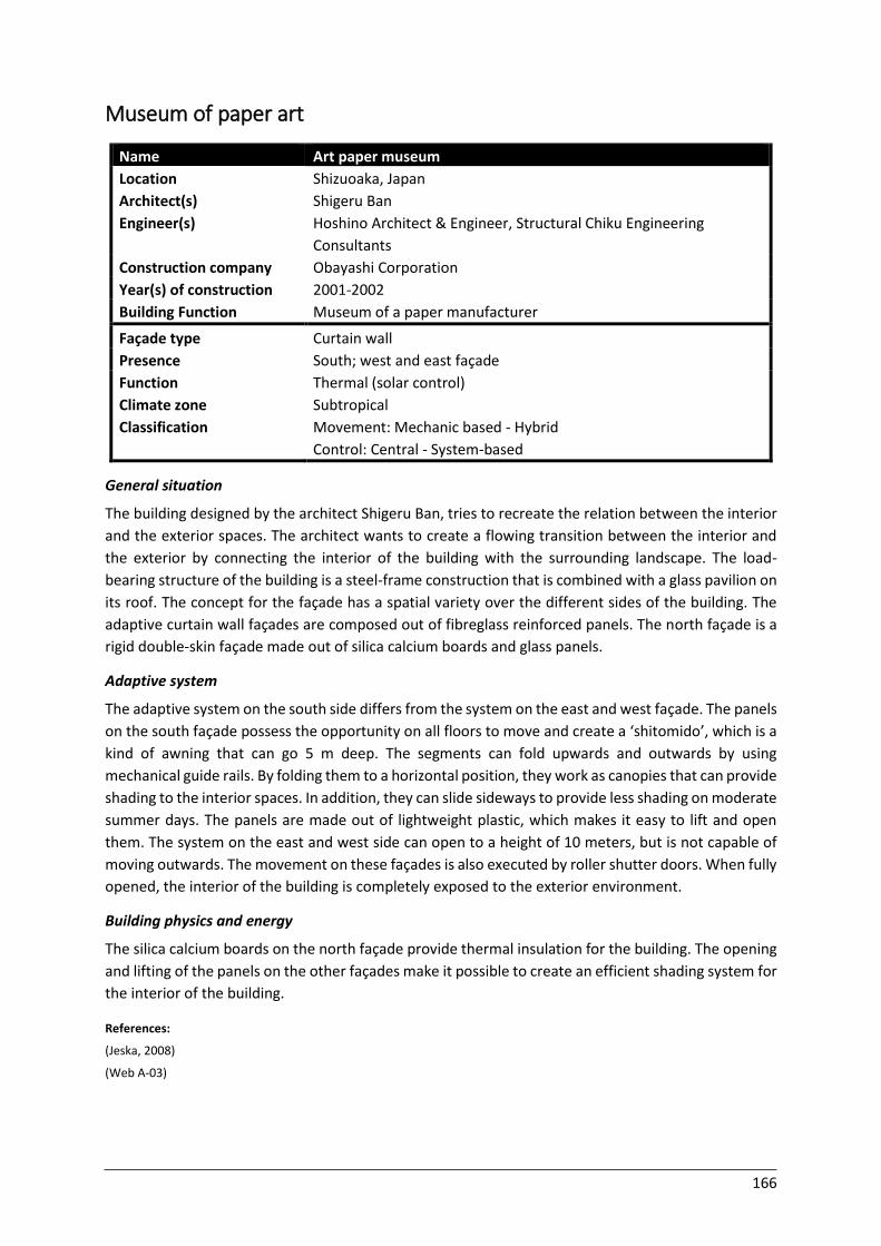
166
Museum of paper art
Name Art paper museum
Location Shizuoaka, Japan
Architect(s) Shigeru Ban
Engineer(s) Hoshino Architect & Engineer, Structural Chiku Engineering
Consultants
Construction company Obayashi Corporation
Year(s) of construction 2001-2002
Building Function Museum of a paper manufacturer
Façade type Curtain wall
Presence South; west and east façade
Function
Climate zone
Classification
Thermal (solar control)
Subtropical
Movement: Mechanic based - Hybrid
Control: Central - System-based General situation
The building designed by the architect Shigeru Ban, tries to recreate the relation between the interior
and the exterior spaces. The architect wants to create a flowing transition between the interior and
the exterior by connecting the interior of the building with the surrounding landscape. The load-
bearing structure of the building is a steel-frame construction that is combined with a glass pavilion on
its roof. The concept for the façade has a spatial variety over the different sides of the building. The
adaptive curtain wall façades are composed out of fibreglass reinforced panels. The north façade is a
rigid double-skin façade made out of silica calcium boards and glass panels.
Adaptive system
The adaptive system on the south side differs from the system on the east and west façade. The panels
on the south façade possess the opportunity on all floors to move and create a ‘shitomido’, which is a
kind of awning that can go 5 m deep. The segments can fold upwards and outwards by using
mechanical guide rails. By folding them to a horizontal position, they work as canopies that can provide
shading to the interior spaces. In addition, they can slide sideways to provide less shading on moderate
summer days. The panels are made out of lightweight plastic, which makes it easy to lift and open
them. The system on the east and west side can open to a height of 10 meters, but is not capable of
moving outwards. The movement on these façades is also executed by roller shutter doors. When fully
opened, the interior of the building is completely exposed to the exterior environment.
Building physics and energy
The silica calcium boards on the north façade provide thermal insulation for the building. The opening
and lifting of the panels on the other façades make it possible to create an efficient shading system for
the interior of the building.
References:
(Jeska, 2008)
(Web A-03)
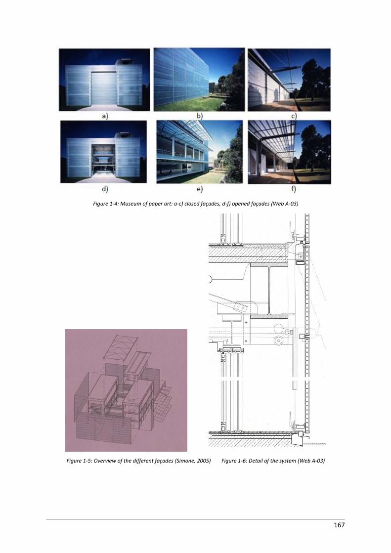
167
Figure 1-4: Museum of paper art: a-c) closed façades, d-f) opened façades (Web A-03)
Figure 1-5: Overview of the different façades (Simone, 2005) Figure 1-6: Detail of the system (Web A-03)
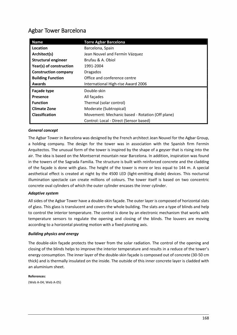
168
Agbar Tower Barcelona
Name Torre Agbar Barcelona
Location Barcelona, Spain
Architect(s) Jean Nouvel and Fermín Vázquez
Structural engineer Brufau & A. Obiol
Year(s) of construction 1991-2004
Construction company Dragados
Building Function Office and conference centre
Awards International High-rise Award 2006
Façade type Double-skin
Presence All façades
Function
Climate Zone
Classification
Thermal (solar control)
Moderate (Subtropical)
Movement: Mechanic based - Rotation (Off plane)
Control: Local - Direct (Sensor based) General concept
The Agbar Tower in Barcelona was designed by the French architect Jean Nouvel for the Agbar Group,
a holding company. The design for the tower was in association with the Spanish firm Fermín
Arquitectos. The unusual form of the tower is inspired by the shape of a geyser that is rising into the
air. The idea is based on the Montserrat mountain near Barcelona. In addition, inspiration was found
in the towers of the Sagrada Familia. The structure is built with reinforced concrete and the cladding
of the façade is done with glass. The height of the tower is more or less equal to 144 m. A special
aesthetical effect is created at night by the 4500 LED (light-emitting diode) devices. This nocturnal
illumination spectacle can create millions of colours. The tower itself is based on two concentric
concrete oval cylinders of which the outer cylinder encases the inner cylinder.
Adaptive system
All sides of the Agbar Tower have a double-skin façade. The outer layer is composed of horizontal slats
of glass. This glass is translucent and covers the whole building. The slats are a type of blinds and help
to control the interior temperature. The control is done by an electronic mechanism that works with
temperature sensors to regulate the opening and closing of the blinds. The louvers are moving
according to a horizontal pivoting motion with a fixed pivoting axis.
Building physics and energy
The double-skin façade protects the tower from the solar radiation. The control of the opening and
closing of the blinds helps to improve the interior temperature and results in a reduce of the tower’s
energy consumption. The inner layer of the double-skin façade is composed out of concrete (30-50 cm
thick) and is thermally insulated on the inside. The outside of this inner concrete layer is cladded with
an aluminium sheet.
References:
(Web A-04; Web A-05)
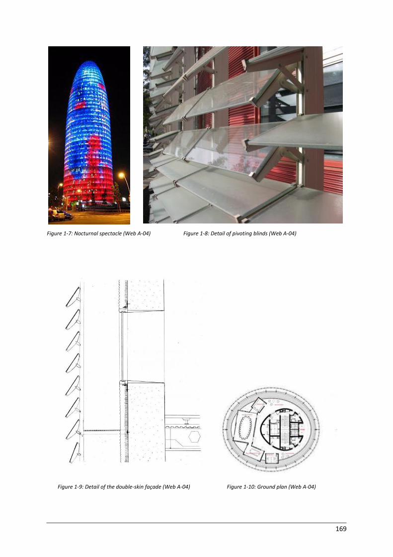
169
Figure 1-7: Nocturnal spectacle (Web A-04) Figure 1-8: Detail of pivoting blinds (Web A-04)
Figure 1-9: Detail of the double-skin façade (Web A-04) Figure 1-10: Ground plan (Web A-04)
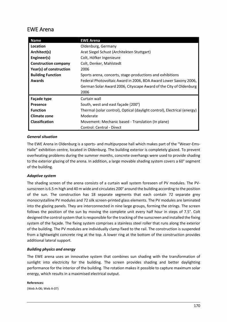
170
EWE Arena
Name EWE Arena
Location Oldenburg, Germany
Architect(s) Arat Siegel Schust (Architekten Stuttgart)
Engineer(s) Colt, Höfker Ingenieure
Construction company Colt, Denker, Mahlstedt
Year(s) of construction 2006
Building Function Sports arena, concerts, stage-productions and exhibitions
Awards Federal Photovoltaic Award in 2006, BDA Award Lower Saxony 2006,
German Solar Award 2006, Cityscape Award of the City of Oldenburg
2006
Façade type Curtain wall
Presence South, west and east façade (200°)
Function
Climate zone
Classification
Thermal (solar control), Optical (daylight control), Electrical (energy)
Moderate
Movement: Mechanic based - Translation (In plane)
Control: Central - Direct General situation
The EWE Arena in Oldenburg is a sports- and multipurpose hall which makes part of the “Weser-Ems-
Halle” exhibition centre, located in Oldenburg. The building exterior is completely glazed. To prevent
overheating problems during the summer months, concrete overhangs were used to provide shading
to the exterior glazing of the arena. In addition, a large movable shading system covers a 60° segment
of the building.
Adaptive system
The shading screen of the arena consists of a curtain wall system foreseen of PV modules. The PV-
sunscreen is 6.5 m high and 40 m wide and circulates 200° around the building according to the position
of the sun. The construction has 18 separate segments that each contain 72 separate grey
monocrystalline PV modules and 72 silk screen-printed glass elements. The PV modules are laminated
into the glazing panels. They are interconnected in nine large groups, forming the strings. The screen
follows the position of the sun by moving the complete unit every half hour in steps of 7.5°. Colt
designed the control system that is responsible for the tracking of the sunscreen and installed the fixing
system of the façade. The fixing system comprises a stainless steel roller that runs along the exterior
of the building. The PV modules are individually clamp fixed to the rail. The construction is suspended
from a lightweight concrete ring at the top. A lower ring at the bottom of the construction provides
additional lateral support.
Building physics and energy
The EWE arena uses an innovative system that combines sun shading with the transformation of
sunlight into electricity for the building. The screen provides shading and better daylighting
performance for the interior of the building. The rotation makes it possible to capture maximum solar
energy, which results in a maximised electrical output.
References:
(Web A-06; Web A-07)
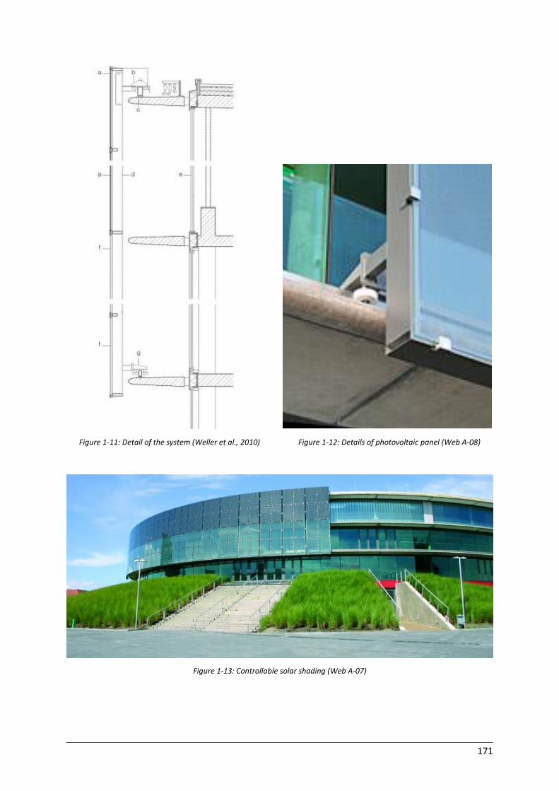
171
Figure 1-11: Detail of the system (Weller et al., 2010) Figure 1-12: Details of photovoltaic panel (Web A-08)
Figure 1-13: Controllable solar shading (Web A-07)
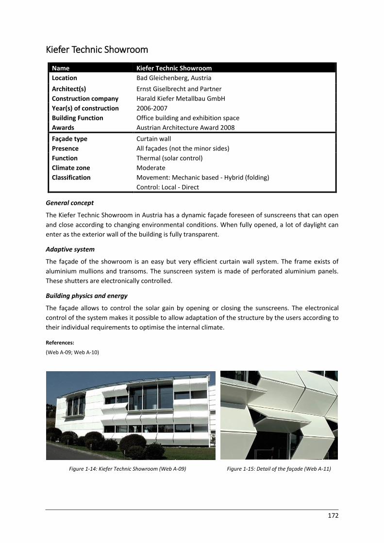
172
Kiefer Technic Showroom
Name Kiefer Technic Showroom
Location Bad Gleichenberg, Austria
Architect(s) Ernst Giselbrecht and Partner
Construction company Harald Kiefer Metallbau GmbH
Year(s) of construction 2006-2007
Building Function Office building and exhibition space
Awards Austrian Architecture Award 2008
Façade type Curtain wall
Presence All façades (not the minor sides)
Function
Climate zone
Classification
Thermal (solar control)
Moderate
Movement: Mechanic based - Hybrid (folding)
Control: Local - Direct General concept
The Kiefer Technic Showroom in Austria has a dynamic façade foreseen of sunscreens that can open
and close according to changing environmental conditions. When fully opened, a lot of daylight can
enter as the exterior wall of the building is fully transparent.
Adaptive system
The façade of the showroom is an easy but very efficient curtain wall system. The frame exists of
aluminium mullions and transoms. The sunscreen system is made of perforated aluminium panels.
These shutters are electronically controlled.
Building physics and energy
The façade allows to control the solar gain by opening or closing the sunscreens. The electronical
control of the system makes it possible to allow adaptation of the structure by the users according to
their individual requirements to optimise the internal climate.
References:
(Web A-09; Web A-10)
Figure 1-14: Kiefer Technic Showroom (Web A-09) Figure 1-15: Detail of the façade (Web A-11)
173
Pola Ginza Building Façade
Name POLA Ginza Building Façade
Location Ginza district, Tokyo, Japan
Architect(s) Hoberman Associates, Yasuda Atelier, Nikken Sekkei
Year(s) of construction 2009
Building Function Showroom building
Awards Environment and Building Service System Design Award 2011
Façade type Double-skin
Presence Front façade
Function
Climate zone
Classification
Thermal (solar gain), Optical (daylight entering), Air flow (ventilation)
Moderate/Subtropical
Movement: Mechanic based - Rotation (Off plane)
Control: Local - Direct General concept
The façade of the new showroom building in the Ginza district in Tokyo was developed in 2009 by The
Adaptive Building Initiative in collaboration with the design architect, Yasuda Atelier and the architect
Nikken Sekkei. The request was done by POLA, a Japanese cosmetics manufacturer. The design is a
shiny, adaptable skin that symbolises the important concepts of ‘water’ and ‘light’ in human life.
Adaptive system
The adaptive concept is inspired on plant concepts and is integrated in the double-skin façade of the
building. The façade of the building exists of 185 individually controlled shutter mechanisms, with a
dimension of one by three meters. The shutters are made out of curved acrylic panels. The panels are
combined with LED lighting which can provide the building of various colours, which makes the building
very attractive at night. The shutters are individually controlled in a motorised way.
Building physics and energy
The double-skin of the building’s façade protects the shading system and allows natural ventilation by
letting cooler air enter the building during night to reduce the cooling load. In addition, it maximises
the natural daylight that enters the building during the whole year and it can increase the solar gain in
the winter.
References:
(Web A-12; Web A-13)
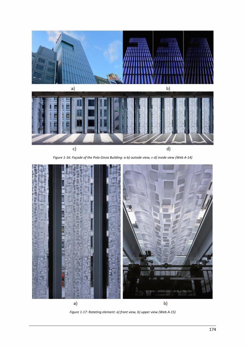
174
Figure 1-16: Façade of the Pola Ginza Building: a-b) outside view, c-d) inside view (Web A-14)
Figure 1-17: Rotating element: a) front view, b) upper view (Web A-15)
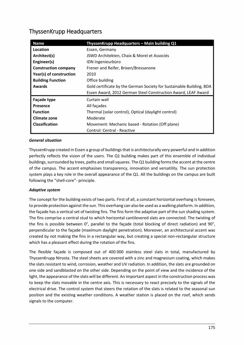
175
ThyssenKrupp Headquarters
Name ThyssenKrupp Headquarters – Main building Q1
Location Essen, Germany
Architect(s) JSWD Architekten, Chaix & Morel et Associés
Engineer(s) IDN Ingenieurbüro
Construction company Frener and Reifer, Brixen/Bressanone
Year(s) of construction 2010
Building Function Office building
Awards Gold certificate by the German Society for Sustainable Building, BDA
Essen Award, 2012 German Steel Construction Award, LEAF Award
Façade type Curtain wall
Presence All façades
Function
Climate zone
Classification
Thermal (solar control), Optical (daylight control)
Moderate
Movement: Mechanic based - Rotation (Off plane)
Control: Central - Reactive General situation
ThyssenKrupp created in Essen a group of buildings that is architecturally very powerful and in addition
perfectly reflects the vision of the users. The Q1 building makes part of this ensemble of individual
buildings, surrounded by trees, paths and small squares. The Q1 building forms the accent at the centre
of the campus. The accent emphasises transparency, innovation and versatility. The sun protection
system plays a key role in the overall appearance of the Q1. All the buildings on the campus are built
following the “shell-core”- principle.
Adaptive system
The concept for the building exists of two parts. First of all, a constant horizontal overhang is foreseen,
to provide protection against the sun. This overhang can also be used as a walking platform. In addition,
the façade has a vertical set of twisting fins. The fins form the adaptive part of the sun shading system.
The fins comprise a central stud to which horizontal cantilevered slats are connected. The twisting of
the fins is possible between 0°, parallel to the façade (total blocking of direct radiation) and 90°,
perpendicular to the façade (maximum daylight penetration). Moreover, an architectural accent was
created by not making the fins in a rectangular way, but creating a special non-rectangular structure
which has a pleasant effect during the rotation of the fins.
The flexible façade is composed out of 400 000 stainless steel slats in total, manufactured by
ThyssenKrupp Nirosta. The steel sheets are covered with a zinc and magnesium coating, which makes
the slats resistant to wind, corrosion, weather and UV radiation. In addition, the slats are grounded on
one side and sandblasted on the other side. Depending on the point of view and the incidence of the
light, the appearance of the slats will be different. An important aspect in the construction process was
to keep the slats movable in the centre axis. This is necessary to react precisely to the signals of the
electrical drive. The control system that steers the rotation of the slats is related to the seasonal sun
position and the existing weather conditions. A weather station is placed on the roof, which sends
signals to the computer.
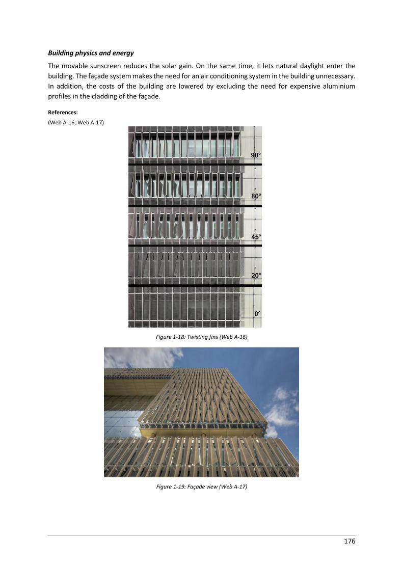
176
Building physics and energy
The movable sunscreen reduces the solar gain. On the same time, it lets natural daylight enter the
building. The façade system makes the need for an air conditioning system in the building unnecessary.
In addition, the costs of the building are lowered by excluding the need for expensive aluminium
profiles in the cladding of the façade.
References:
(Web A-16; Web A-17)
Figure 1-18: Twisting fins (Web A-16)
Figure 1-19: Façade view (Web A-17)
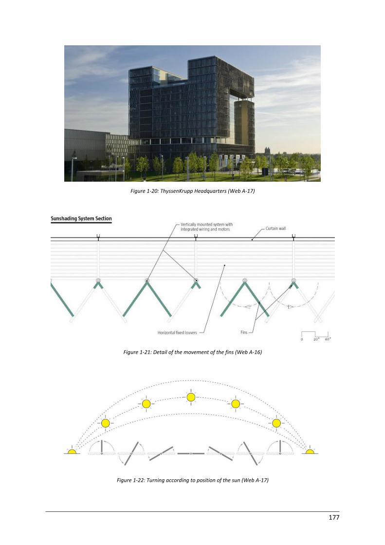
177
Figure 1-20: ThyssenKrupp Headquarters (Web A-17)
Figure 1-21: Detail of the movement of the fins (Web A-16)
Figure 1-22: Turning according to position of the sun (Web A-17)
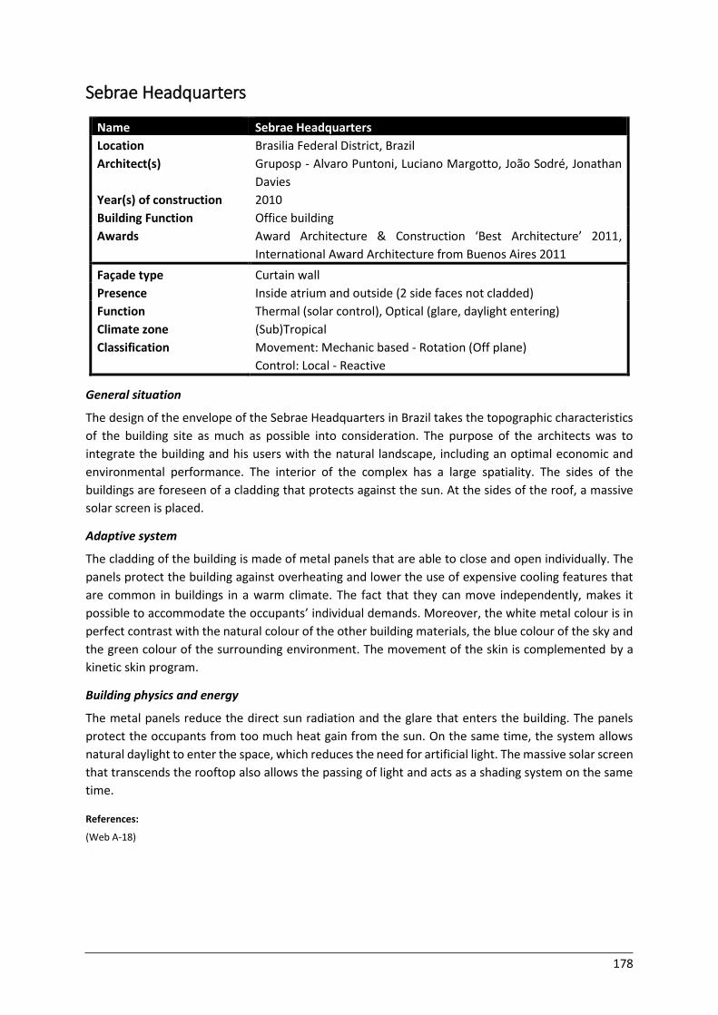
178
Sebrae Headquarters
Name Sebrae Headquarters
Location Brasilia Federal District, Brazil
Architect(s) Gruposp - Alvaro Puntoni, Luciano Margotto, João Sodré, Jonathan
Davies
Year(s) of construction 2010
Building Function Office building
Awards Award Architecture & Construction ‘Best Architecture’ 2011,
International Award Architecture from Buenos Aires 2011
Façade type Curtain wall
Presence Inside atrium and outside (2 side faces not cladded)
Function
Climate zone
Classification
Thermal (solar control), Optical (glare, daylight entering)
(Sub)Tropical
Movement: Mechanic based - Rotation (Off plane)
Control: Local - Reactive General situation
The design of the envelope of the Sebrae Headquarters in Brazil takes the topographic characteristics
of the building site as much as possible into consideration. The purpose of the architects was to
integrate the building and his users with the natural landscape, including an optimal economic and
environmental performance. The interior of the complex has a large spatiality. The sides of the
buildings are foreseen of a cladding that protects against the sun. At the sides of the roof, a massive
solar screen is placed.
Adaptive system
The cladding of the building is made of metal panels that are able to close and open individually. The
panels protect the building against overheating and lower the use of expensive cooling features that
are common in buildings in a warm climate. The fact that they can move independently, makes it
possible to accommodate the occupants’ individual demands. Moreover, the white metal colour is in
perfect contrast with the natural colour of the other building materials, the blue colour of the sky and
the green colour of the surrounding environment. The movement of the skin is complemented by a
kinetic skin program.
Building physics and energy
The metal panels reduce the direct sun radiation and the glare that enters the building. The panels
protect the occupants from too much heat gain from the sun. On the same time, the system allows
natural daylight to enter the space, which reduces the need for artificial light. The massive solar screen
that transcends the rooftop also allows the passing of light and acts as a shading system on the same
time.
References:
(Web A-18)
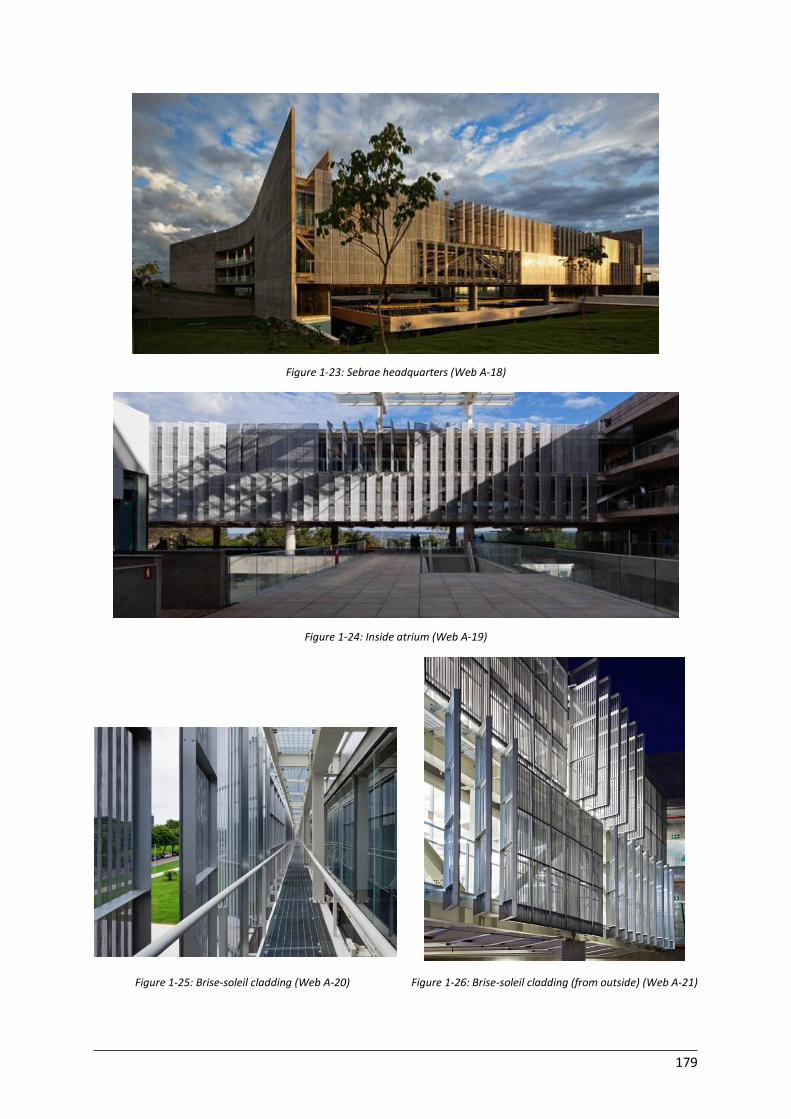
179
Figure 1-23: Sebrae headquarters (Web A-18)
Figure 1-24: Inside atrium (Web A-19)
Figure 1-25: Brise-soleil cladding (Web A-20) Figure 1-26: Brise-soleil cladding (from outside) (Web A-21)
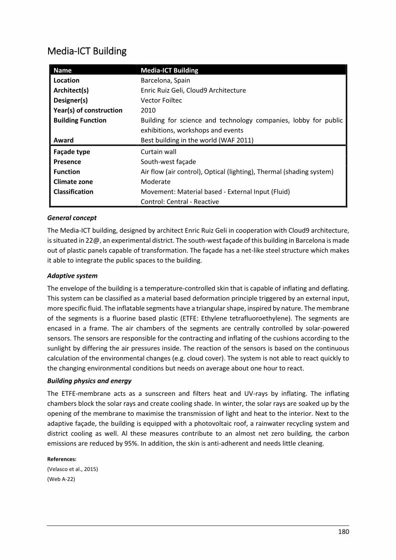
180
Media-ICT Building
Name Media-ICT Building
Location Barcelona, Spain
Architect(s) Enric Ruiz Geli, Cloud9 Architecture
Designer(s) Vector Foiltec
Year(s) of construction 2010
Building Function
Award
Building for science and technology companies, lobby for public
exhibitions, workshops and events
Best building in the world (WAF 2011)
Façade type Curtain wall
Presence South-west façade
Function
Climate zone
Classification
Air flow (air control), Optical (lighting), Thermal (shading system)
Moderate
Movement: Material based - External Input (Fluid)
Control: Central - Reactive General concept
The Media-ICT building, designed by architect Enric Ruiz Geli in cooperation with Cloud9 architecture,
is situated in 22@, an experimental district. The south-west façade of this building in Barcelona is made
out of plastic panels capable of transformation. The façade has a net-like steel structure which makes
it able to integrate the public spaces to the building.
Adaptive system
The envelope of the building is a temperature-controlled skin that is capable of inflating and deflating.
This system can be classified as a material based deformation principle triggered by an external input,
more specific fluid. The inflatable segments have a triangular shape, inspired by nature. The membrane
of the segments is a fluorine based plastic (ETFE: Ethylene tetrafluoroethylene). The segments are
encased in a frame. The air chambers of the segments are centrally controlled by solar-powered
sensors. The sensors are responsible for the contracting and inflating of the cushions according to the
sunlight by differing the air pressures inside. The reaction of the sensors is based on the continuous
calculation of the environmental changes (e.g. cloud cover). The system is not able to react quickly to
the changing environmental conditions but needs on average about one hour to react.
Building physics and energy
The ETFE-membrane acts as a sunscreen and filters heat and UV-rays by inflating. The inflating
chambers block the solar rays and create cooling shade. In winter, the solar rays are soaked up by the
opening of the membrane to maximise the transmission of light and heat to the interior. Next to the
adaptive façade, the building is equipped with a photovoltaic roof, a rainwater recycling system and
district cooling as well. Al these measures contribute to an almost net zero building, the carbon
emissions are reduced by 95%. In addition, the skin is anti-adherent and needs little cleaning.
References:
(Velasco et al., 2015)
(Web A-22)

181
Figure 1-27: Media ICT-building (Web A-22)
Figure 1-28: Air cushions (Web A-22) Figure 1-29: Detail of the inflating cushions (Web A-22)
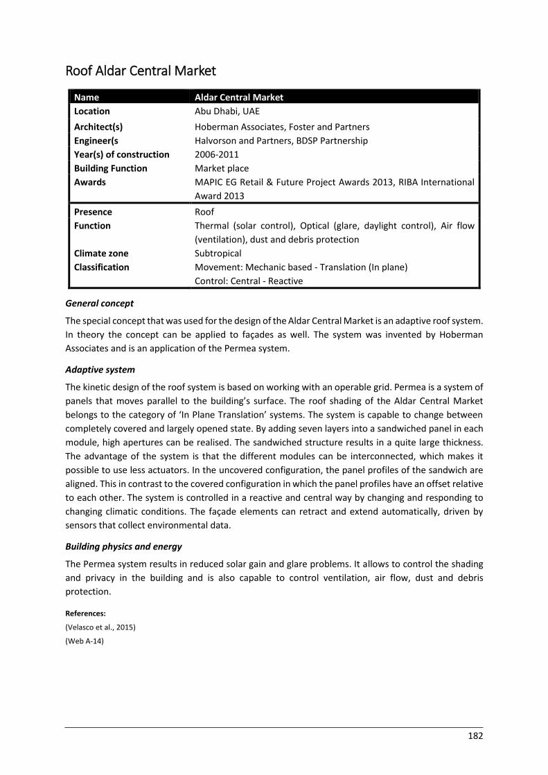
182
Roof Aldar Central Market
Name Aldar Central Market
Location Abu Dhabi, UAE
Architect(s) Hoberman Associates, Foster and Partners
Engineer(s Halvorson and Partners, BDSP Partnership
Year(s) of construction 2006-2011
Building Function Market place
Awards MAPIC EG Retail & Future Project Awards 2013, RIBA International
Award 2013
Presence Roof
Function
Climate zone
Classification
Thermal (solar control), Optical (glare, daylight control), Air flow
(ventilation), dust and debris protection
Subtropical
Movement: Mechanic based - Translation (In plane)
Control: Central - Reactive General concept
The special concept that was used for the design of the Aldar Central Market is an adaptive roof system.
In theory the concept can be applied to façades as well. The system was invented by Hoberman
Associates and is an application of the Permea system.
Adaptive system
The kinetic design of the roof system is based on working with an operable grid. Permea is a system of
panels that moves parallel to the building’s surface. The roof shading of the Aldar Central Market
belongs to the category of ‘In Plane Translation’ systems. The system is capable to change between
completely covered and largely opened state. By adding seven layers into a sandwiched panel in each
module, high apertures can be realised. The sandwiched structure results in a quite large thickness.
The advantage of the system is that the different modules can be interconnected, which makes it
possible to use less actuators. In the uncovered configuration, the panel profiles of the sandwich are
aligned. This in contrast to the covered configuration in which the panel profiles have an offset relative
to each other. The system is controlled in a reactive and central way by changing and responding to
changing climatic conditions. The façade elements can retract and extend automatically, driven by
sensors that collect environmental data.
Building physics and energy
The Permea system results in reduced solar gain and glare problems. It allows to control the shading
and privacy in the building and is also capable to control ventilation, air flow, dust and debris
protection.
References:
(Velasco et al., 2015)
(Web A-14)
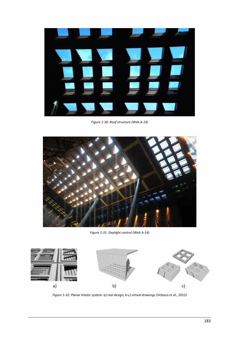
183
Figure 1-30: Roof structure (Web A-14)
Figure 1-31: Daylight control (Web A-14)
Figure 1-32: Planar kinetic system: a) real design, b-c) virtual drawings (Velasco et al., 2015)
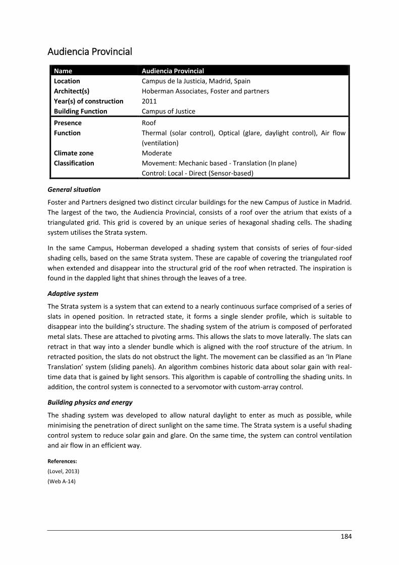
184
Audiencia Provincial
Name Audiencia Provincial
Location Campus de la Justicia, Madrid, Spain
Architect(s) Hoberman Associates, Foster and partners
Year(s) of construction 2011
Building Function Campus of Justice
Presence Roof
Function
Climate zone
Classification
Thermal (solar control), Optical (glare, daylight control), Air flow
(ventilation)
Moderate
Movement: Mechanic based - Translation (In plane)
Control: Local - Direct (Sensor-based) General situation
Foster and Partners designed two distinct circular buildings for the new Campus of Justice in Madrid.
The largest of the two, the Audiencia Provincial, consists of a roof over the atrium that exists of a
triangulated grid. This grid is covered by an unique series of hexagonal shading cells. The shading
system utilises the Strata system.
In the same Campus, Hoberman developed a shading system that consists of series of four-sided
shading cells, based on the same Strata system. These are capable of covering the triangulated roof
when extended and disappear into the structural grid of the roof when retracted. The inspiration is
found in the dappled light that shines through the leaves of a tree.
Adaptive system
The Strata system is a system that can extend to a nearly continuous surface comprised of a series of
slats in opened position. In retracted state, it forms a single slender profile, which is suitable to
disappear into the building’s structure. The shading system of the atrium is composed of perforated
metal slats. These are attached to pivoting arms. This allows the slats to move laterally. The slats can
retract in that way into a slender bundle which is aligned with the roof structure of the atrium. In
retracted position, the slats do not obstruct the light. The movement can be classified as an ‘In Plane
Translation’ system (sliding panels). An algorithm combines historic data about solar gain with real-
time data that is gained by light sensors. This algorithm is capable of controlling the shading units. In
addition, the control system is connected to a servomotor with custom-array control.
Building physics and energy
The shading system was developed to allow natural daylight to enter as much as possible, while
minimising the penetration of direct sunlight on the same time. The Strata system is a useful shading
control system to reduce solar gain and glare. On the same time, the system can control ventilation
and air flow in an efficient way.
References:
(Lovel, 2013)
(Web A-14)
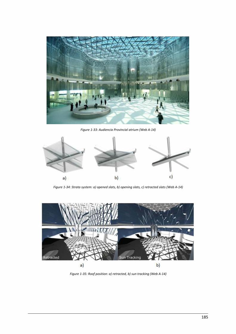
185
Figure 1-33: Audiencia Provincial atrium (Web A-14)
Figure 1-34: Strata system: a) opened slats, b) opening slats, c) retracted slats (Web A-14)
Figure 1-35: Roof position: a) retracted, b) sun tracking (Web A-14)
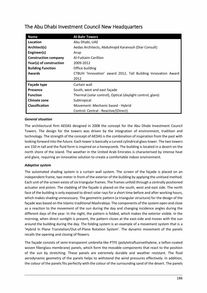
186
The Abu Dhabi Investment Council New Headquarters
Name Al-Bahr Towers
Location Abu Dhabi, UAE
Architect(s) Aedas Architects, Abdulmajid Karanouh (Diar Consult)
Engineer(s) Arup
Construction company Al-Futtaim Carillion
Year(s) of construction 2009-2012
Building Function Office building
Awards CTBUH ‘Innovation’ award 2012, Tall Building Innovation Award
2012
Façade type Curtain wall
Presence South, west and east façade
Function
Climate zone
Thermal (solar control), Optical (daylight control, glare)
Subtropical
Classification Movement: Mechanic based - Hybrid
Control: Central - Reactive/(Direct) General situation
The architectural firm AEDAS designed in 2008 the concept for the Abu Dhabi Investment Council
Towers. The design for the towers was driven by the integration of environment, tradition and
technology. The strength of the concept of AEDAS is the combination of inspiration from the past with
looking forward into the future. Each tower is basically a curved cylindrical glass tower. The two towers
are 150 m tall and the fluid form is inspired on a honeycomb. The building is located in a desert on the
north shore of the island. The weather in the United Arab Emirates is characterised by intense heat
and glare, requiring an innovative solution to create a comfortable indoor environment.
Adaptive system
The automated shading system is a curtain wall system. The screen of the façade is placed on an
independent frame, two meter in front of the exterior of the building by applying the unitised method.
Each unit of the screen exists of six triangular frames. The frames unfold through a centrally positioned
actuator and piston. The cladding of the façade is placed on the south, west and east side. The north
face of the building is only exposed to direct solar rays for a short time before and after working hours,
which makes shading unnecessary. The geometric pattern (a triangular structure) for the design of the
façade was based on the Islamic traditional Mashrabiya. The components of the system open and close
as a reaction to the movement of the sun during the day and changing incidence angles during the
different days of the year. In the night, the pattern is folded, which makes the exterior visible. In the
morning, when direct sunlight is present, the pattern closes at the east-side and moves with the sun
around the building during the day. The folding system is an example of a movement system that is a
‘Hybrid In Plane Translation/Out-of-Plane Rotation System’. The dynamic movement of the panels
recalls the opening and closing of flowers.
The façade consists of semi-transparent umbrella-like PTFE (polytetrafluoroethylene, a teflon-coated
woven fiberglass membrane) panels, which form the movable components that react to the position
of the sun by stretching. These panels are extremely durable and weather resistant. The fluid
aerodynamic geometry of the panels helps to withstand the wind pressures effectively. In addition,
the colour of the panels fits perfectly with the colour of the surrounding sand of the desert. The panels
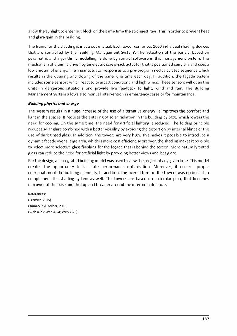
187
allow the sunlight to enter but block on the same time the strongest rays. This in order to prevent heat
and glare gain in the building.
The frame for the cladding is made out of steel. Each tower comprises 1000 individual shading devices
that are controlled by the ‘Building Management System’. The actuation of the panels, based on
parametric and algorithmic modelling, is done by control software in this management system. The
mechanism of a unit is driven by an electric screw-jack actuator that is positioned centrally and uses a
low amount of energy. The linear actuator responses to a pre-programmed calculated sequence which
results in the opening and closing of the panel one time each day. In addition, the façade system
includes some sensors which react to overcast conditions and high winds. These sensors will open the
units in dangerous situations and provide live feedback to light, wind and rain. The Building
Management System allows also manual intervention in emergency cases or for maintenance.
Building physics and energy
The system results in a huge increase of the use of alternative energy. It improves the comfort and
light in the spaces. It reduces the entering of solar radiation in the building by 50%, which lowers the
need for cooling. On the same time, the need for artificial lighting is reduced. The folding principle
reduces solar glare combined with a better visibility by avoiding the distortion by internal blinds or the
use of dark tinted glass. In addition, the towers are very high. This makes it possible to introduce a
dynamic façade over a large area, which is more cost efficient. Moreover, the shading makes it possible
to select more selective glass finishing for the façade that is behind the screen. More naturally tinted
glass can reduce the need for artificial light by providing better views and less glare.
For the design, an integrated building model was used to view the project at any given time. This model
creates the opportunity to facilitate performance optimisation. Moreover, it ensures proper
coordination of the building elements. In addition, the overall form of the towers was optimised to
complement the shading system as well. The towers are based on a circular plan, that becomes
narrower at the base and the top and broader around the intermediate floors.
References:
(Premier, 2015)
(Karanouh & Kerber, 2015)
(Web A-23; Web A-24; Web A-25)
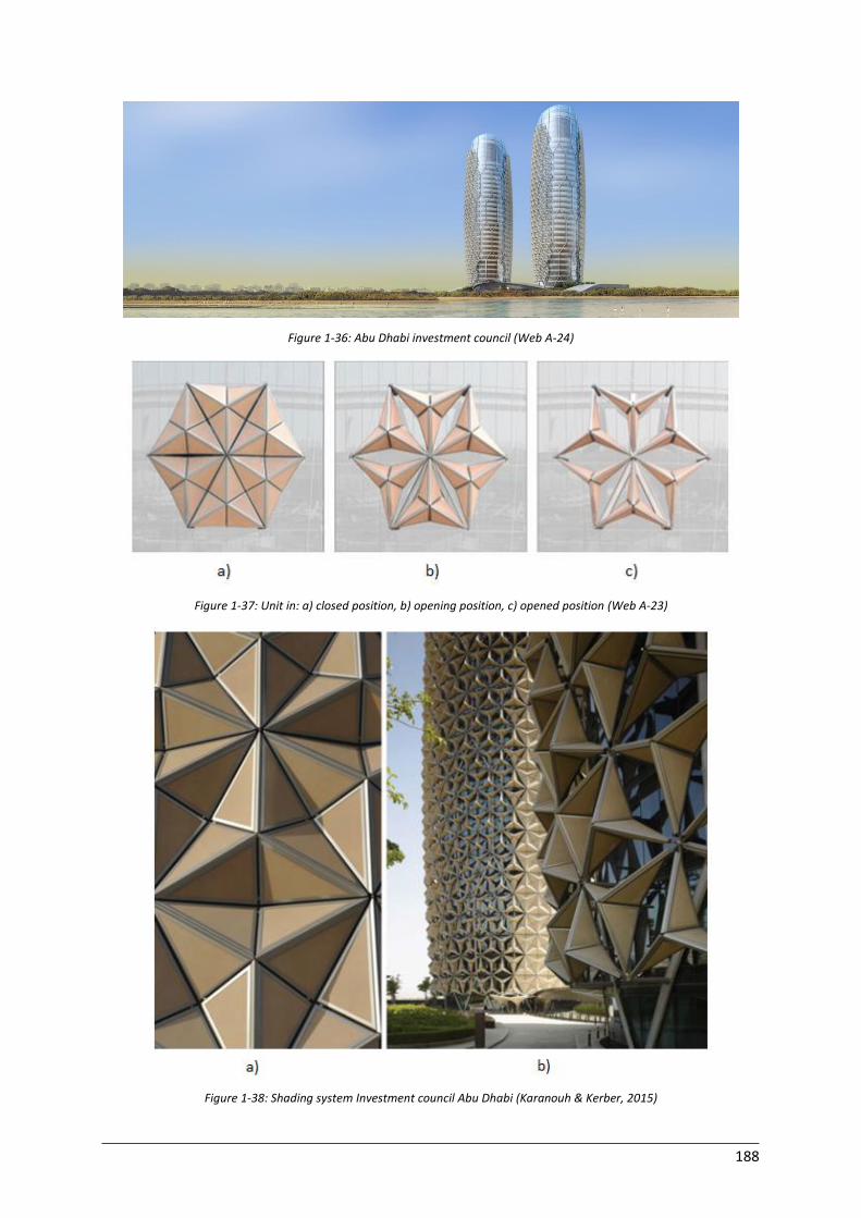
188
Figure 1-36: Abu Dhabi investment council (Web A-24)
Figure 1-37: Unit in: a) closed position, b) opening position, c) opened position (Web A-23)
Figure 1-38: Shading system Investment council Abu Dhabi (Karanouh & Kerber, 2015)
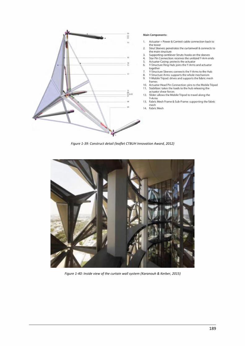
189
Figure 1-39: Construct detail (leaflet CTBUH Innovation Award, 2012)
Figure 1-40: Inside view of the curtain wall system (Karanouh & Kerber, 2015)
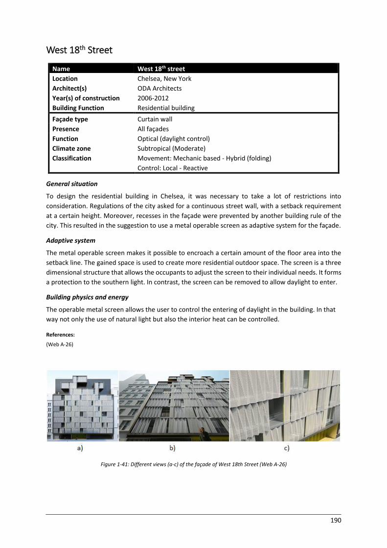
190
West 18th Street
Name West 18th street
Location Chelsea, New York
Architect(s) ODA Architects
Year(s) of construction 2006-2012
Building Function Residential building
Façade type Curtain wall
Presence All façades
Function
Climate zone
Classification
Optical (daylight control)
Subtropical (Moderate)
Movement: Mechanic based - Hybrid (folding)
Control: Local - Reactive General situation
To design the residential building in Chelsea, it was necessary to take a lot of restrictions into
consideration. Regulations of the city asked for a continuous street wall, with a setback requirement
at a certain height. Moreover, recesses in the façade were prevented by another building rule of the
city. This resulted in the suggestion to use a metal operable screen as adaptive system for the façade.
Adaptive system
The metal operable screen makes it possible to encroach a certain amount of the floor area into the
setback line. The gained space is used to create more residential outdoor space. The screen is a three
dimensional structure that allows the occupants to adjust the screen to their individual needs. It forms
a protection to the southern light. In contrast, the screen can be removed to allow daylight to enter.
Building physics and energy
The operable metal screen allows the user to control the entering of daylight in the building. In that
way not only the use of natural light but also the interior heat can be controlled.
References:
(Web A-26)
Figure 1-41: Different views (a-c) of the façade of West 18th Street (Web A-26)
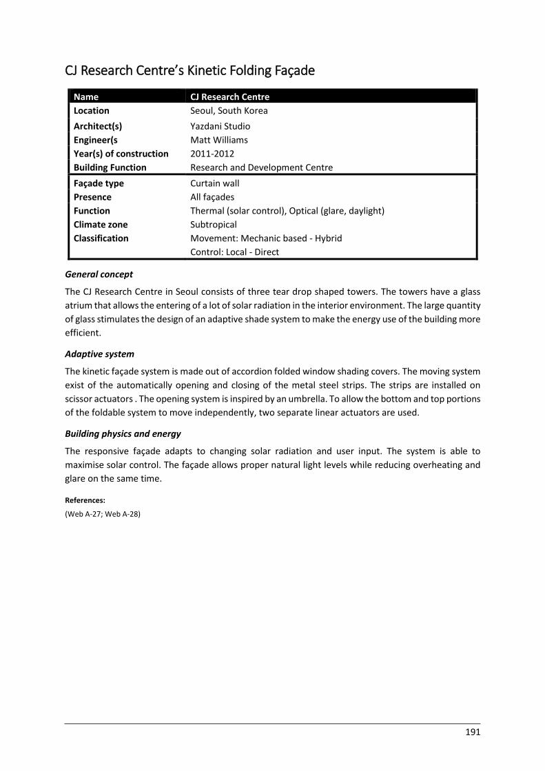
191
CJ Research Centre’s Kinetic Folding Façade
Name CJ Research Centre
Location Seoul, South Korea
Architect(s) Yazdani Studio
Engineer(s Matt Williams
Year(s) of construction 2011-2012
Building Function Research and Development Centre
Façade type Curtain wall
Presence All façades
Function
Climate zone
Classification
Thermal (solar control), Optical (glare, daylight)
Subtropical
Movement: Mechanic based - Hybrid
Control: Local - Direct General concept
The CJ Research Centre in Seoul consists of three tear drop shaped towers. The towers have a glass
atrium that allows the entering of a lot of solar radiation in the interior environment. The large quantity
of glass stimulates the design of an adaptive shade system to make the energy use of the building more
efficient.
Adaptive system
The kinetic façade system is made out of accordion folded window shading covers. The moving system
exist of the automatically opening and closing of the metal steel strips. The strips are installed on
scissor actuators . The opening system is inspired by an umbrella. To allow the bottom and top portions
of the foldable system to move independently, two separate linear actuators are used.
Building physics and energy
The responsive façade adapts to changing solar radiation and user input. The system is able to
maximise solar control. The façade allows proper natural light levels while reducing overheating and
glare on the same time.
References:
(Web A-27; Web A-28)

192
Figure 1-42: CJ R&D centre (Web A-28)
Figure 1-43: Folding system with scissors (Web A-28)
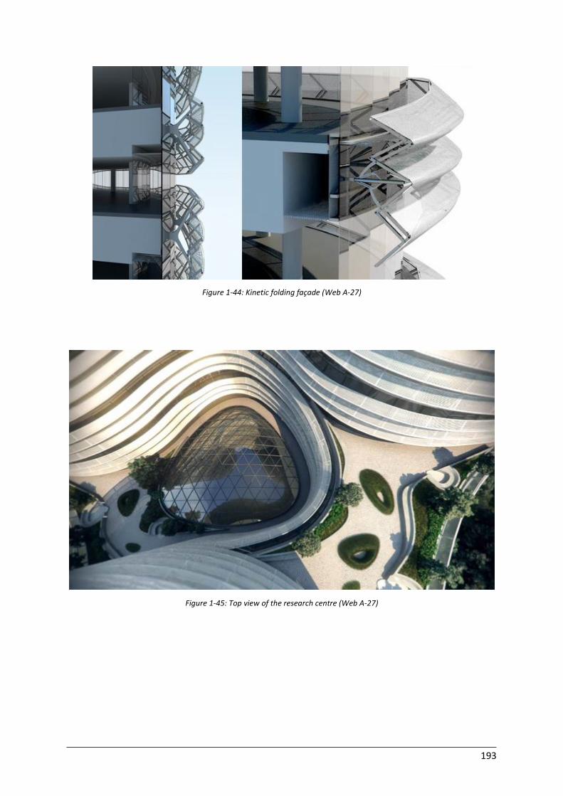
193
Figure 1-44: Kinetic folding façade (Web A-27)
Figure 1-45: Top view of the research centre (Web A-27)
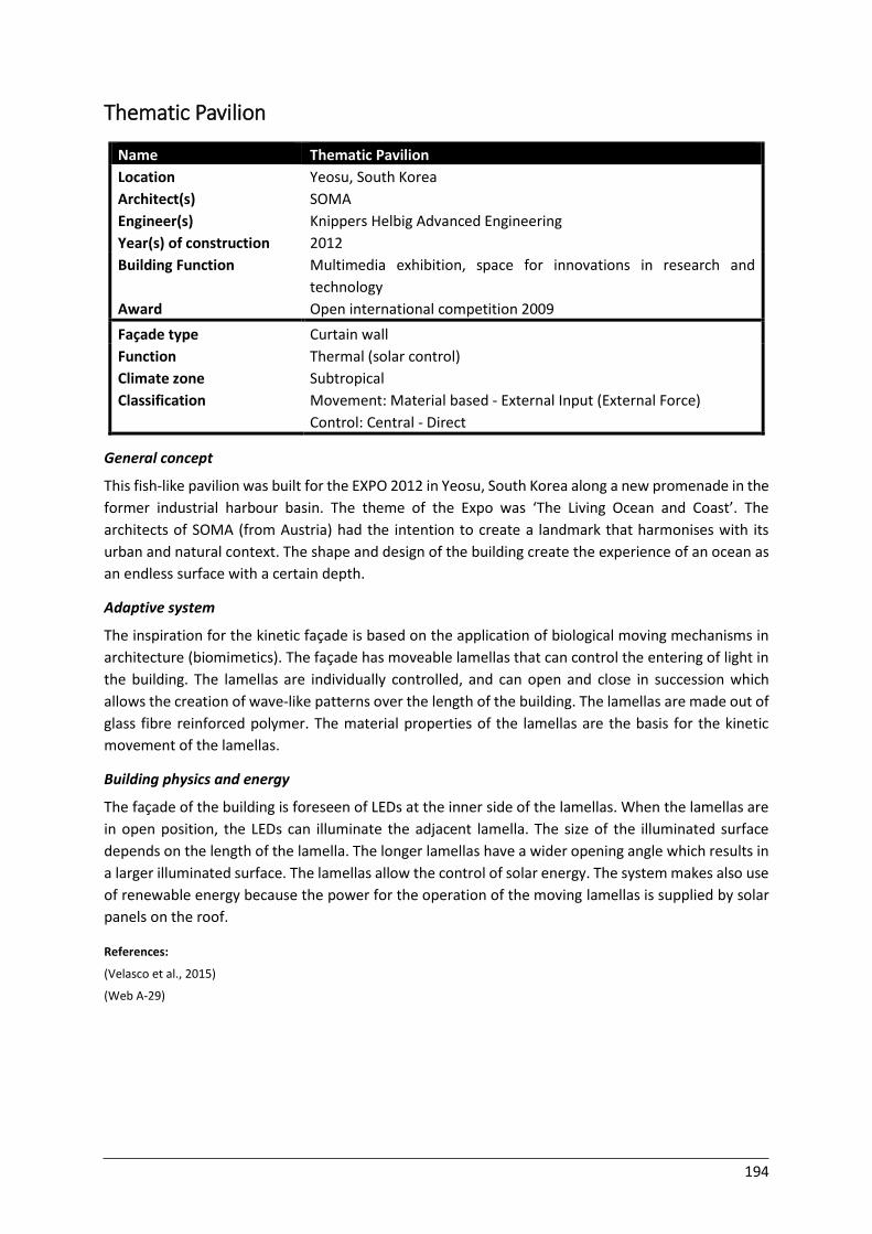
194
Thematic Pavilion
Name Thematic Pavilion
Location Yeosu, South Korea
Architect(s) SOMA
Engineer(s) Knippers Helbig Advanced Engineering
Year(s) of construction 2012
Building Function
Award
Multimedia exhibition, space for innovations in research and
technology
Open international competition 2009
Façade type Curtain wall
Function
Climate zone
Classification
Thermal (solar control)
Subtropical
Movement: Material based - External Input (External Force)
Control: Central - Direct General concept
This fish-like pavilion was built for the EXPO 2012 in Yeosu, South Korea along a new promenade in the
former industrial harbour basin. The theme of the Expo was ‘The Living Ocean and Coast’. The
architects of SOMA (from Austria) had the intention to create a landmark that harmonises with its
urban and natural context. The shape and design of the building create the experience of an ocean as
an endless surface with a certain depth.
Adaptive system
The inspiration for the kinetic façade is based on the application of biological moving mechanisms in
architecture (biomimetics). The façade has moveable lamellas that can control the entering of light in
the building. The lamellas are individually controlled, and can open and close in succession which
allows the creation of wave-like patterns over the length of the building. The lamellas are made out of
glass fibre reinforced polymer. The material properties of the lamellas are the basis for the kinetic
movement of the lamellas.
Building physics and energy
The façade of the building is foreseen of LEDs at the inner side of the lamellas. When the lamellas are
in open position, the LEDs can illuminate the adjacent lamella. The size of the illuminated surface
depends on the length of the lamella. The longer lamellas have a wider opening angle which results in
a larger illuminated surface. The lamellas allow the control of solar energy. The system makes also use
of renewable energy because the power for the operation of the moving lamellas is supplied by solar
panels on the roof.
References:
(Velasco et al., 2015)
(Web A-29)
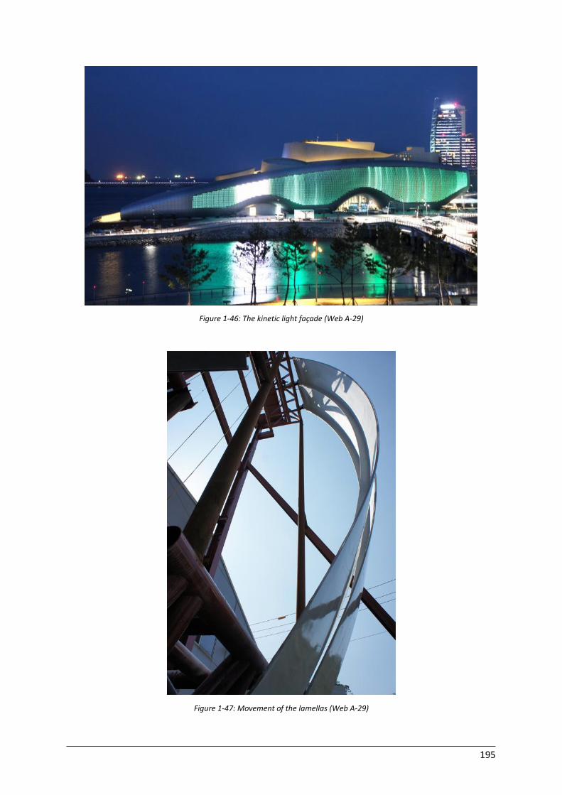
195
Figure 1-46: The kinetic light façade (Web A-29)
Figure 1-47: Movement of the lamellas (Web A-29)
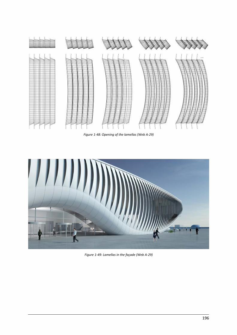
196
Figure 1-48: Opening of the lamellas (Web A-29)
Figure 1-49: Lamellas in the façade (Web A-29)

197
Media Headquarters building
General concept
The two towers that form the Media Headquarters building were designed by REX for the two sister
Middle Eastern Media Companies. The company wanted the headquarter to be in perfect relation with
the traditional Arab iconography. REX designed ultra-thin, stone-clad towers combined with an array
of retractable sunshades with a shape inspired by the Mashrabiya pattern. The towers form long,
slender buildings with offices and other facilities for the two sister companies.
Adaptive system
The blossoming shading of the tower is created by deploying sunshades with a diameter of about 15
meter. The deploying of the sun shadings is executed from the cavities between the floors. The
deployable umbrellas are retracted when the courtyards of the building are in the shadow and
expanded when they are exposed to light. The opening and closing of the system is possible in a few
minutes and follows the rotation of the sun. The sunshade elements are able to retract completely in
the cavity, making the simple, stone-clad towers visible in an easy way. While the sun tracks across the
sky, the entire façade transforms at one side, while it retracts in 60 seconds at the other side. This is
done once a day at a specific moment according to the position of the sun.
Building physics and energy
The sunshade systems on the eastern and western façade protect the building from the sun in an
efficient way. In the caps of the sunshade umbrellas on the east façades, LEDs are integrated. With this
LEDs a light media spectacle can be created at night.
In addition, the sunscreens are effective for the adjoining surroundings. The courtyards are exposed if
they are in the shadow and covered by the umbrella system when in sunlight.
References:
(Kolarevic & Parlac, 2015)
(Web A-30; Web A-31)
Name Conjoined Media Towers
Location Doha, Qatar
Architect(s) REX architects
Year(s) of construction 2013
Building Function Office, studios and facilities for sister media companies
Awards AR MIPIM Future Project Awards/Tall Buildings High Commendation
2015, Azure Magazine AZ Awards 2014, People’s Choice Award 2014
Façade type Curtain wall
Presence West and east façade
Function
Climate zone
Classification
Solar control
Subtropical
Movement: Mechanic based - Hybrid
Control: Central - Reactive
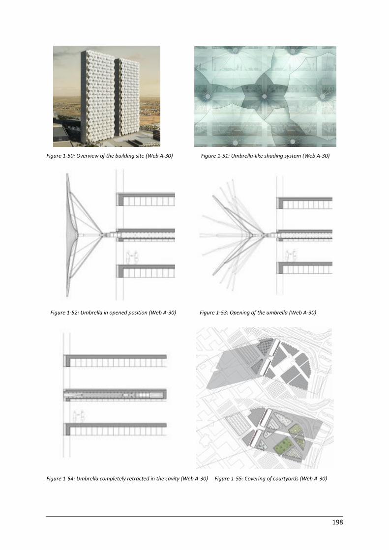
198
Figure 1-50: Overview of the building site (Web A-30) Figure 1-51: Umbrella-like shading system (Web A-30)
Figure 1-52: Umbrella in opened position (Web A-30) Figure 1-53: Opening of the umbrella (Web A-30)
Figure 1-54: Umbrella completely retracted in the cavity (Web A-30) Figure 1-55: Covering of courtyards (Web A-30)
199
Solarleaf Bioreactor Façade
Name Solarleaf
Location Hamburg, Germany
Architect(s) Splitterwerk Architects
Engineer(s) SSC Strategic Science Consult GmbH
Year(s) of construction 2013
Construction company Colt and Arup
Building Function Experimental design
Awards Zumtobel Group Award 2014
Façade type Curtain wall
Presence South façade
Function
Climate zone
Air flow (CO2 balance), Thermal, Acoustic performance
Moderate General concept
The Solarleaf façade uses algal biomass in combination with solar thermal heat to create a dynamic
system. The system is a cooperation of the companies Colt and Arup. The algal biomass in the vertical
glass louvres is created by conversion of daylight and CO2 by the water in the louvres that contains
nutrients. Furthermore, thermal effects from sun gain result in the heating up of the water inside the
louvres. The biomass, which has a high energy content, and heat generation is exchanged and
separated in a closed loop system.
Adaptive system
The Solarleaf façade works as a rainscreen system and forms the curtain wall of the building. The
elements rotate according to the position of the sun. The photobioreactor, in which water circulates
and algae grow, is on both sides foreseen of laminated safety glass. In addition, at the bottom part of
the bioreactor, compressed air is introduced at several times. This stimulates the inflow of CO2 and
light by the algae. Moreover, it results in some natural maintenance: the compressed air creates a
mixture of water and air that washes the inner surfaces of the panels. The transparency of the façades
can be regulated by varying the cell density of the biomass. This density is regulated in a central
building management system.
Building physics and energy
The bioreactor system helps to reduce the CO2 emissions of the building. In addition, it increases the
thermal and acoustic performance of the building. The system is an ideal application for high south
faced façades. The fact that the system is based on biomass is advantageous over photovoltaic
systems. For biomass no expensive storage is needed. Moreover, the efficiency of the solar thermal
system is 60-65%, contrarily to the efficiency of photovoltaics, which have an efficiency of 12-20%. The
biochemical process, the conversion of light to biomass, is facilitated by microalgae. The microalgae
are responsible for the conversion of CO2 because each single cell in the microalgae is capable of
photosynthetics.
References:
(Colt et al., 2013)
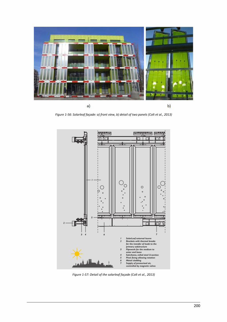
200
Figure 1-56: Solarleaf façade: a) front view, b) detail of two panels (Colt et al., 2013)
Figure 1-57: Detail of the solarleaf façade (Colt et al., 2013)

201
2 Prototypes
Adaptive Solar Façade
Name Adaptive solar façade
Location Chelsea, New York
Architect(s) ODA Architects
Façade type Curtain wall
Function
Classification
Thermal (solar control), Optical (daylight control), Electrical (Energy gain)
Movement: Mechanic based - Rotation (Off plane)
Control: Central - System-based General concept
The adaptive solar façade is a kind of dynamic façade based on the use of thin film photovoltaic
modules. The dynamic façade makes part of the recent research to explore new methods for the
integration of photovoltaic modules in building architecture.
Adaptive system
The photovoltaic modules are combined with the use of soft pneumatic actuators. These actuators can
control the solar tracking and the enter of daylight. The modules rotate in response to environmental
changes. In addition the occupants can rotate the elements to their personal needs. The control of the
rotation is based on sensors, which react to environmental changes and occupant input. The modules
are in addition improved by using adaptive algorithms that help the continuous adaptation of the
behaviour of the modules.
Building physics and energy
The modules are able to control the visibility and the transparency of the façade. In addition, the
system provides shading for the inner spaces and it can generate solar energy. By responding to the
desires of the occupants, the system is able to increase the comfort. Moreover, the panels of the
façade are lightweight and can be mounted almost everywhere on existing buildings.
References:
(Web A-32)
Figure 2-1: Prototype Solar Façade (Web A-32)
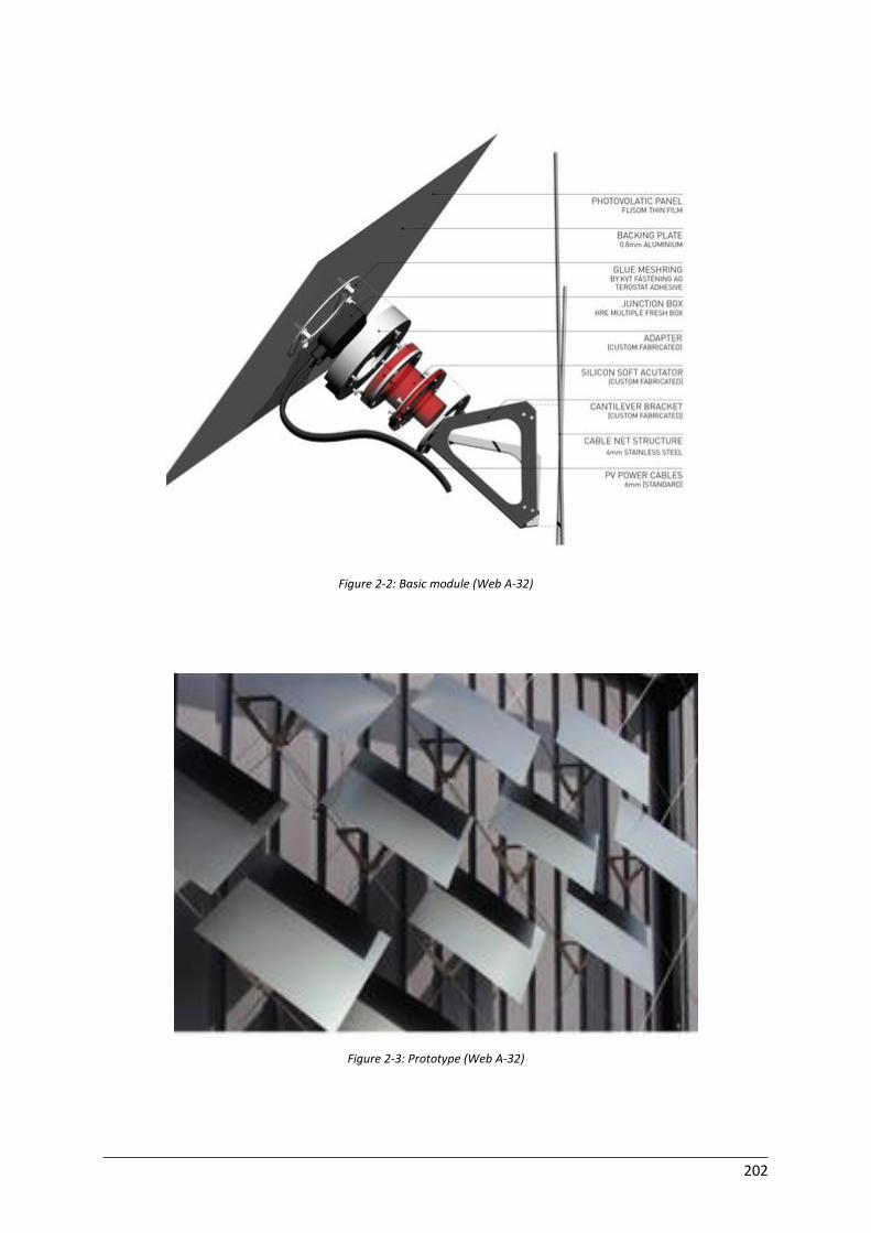
202
Figure 2-2: Basic module (Web A-32)
Figure 2-3: Prototype (Web A-32)

203
Kinetower
Name Kinetower
Location Damme, Belgium
Architect(s) Kinetura (Barbara van Biervliet and Xaveer Claerhout)
Façade type Double-skin
Function
Classification
Optical (daylight control), Electrical (regulation of energy)
Movement: Material based - Self-change
Control: Local - Direct General concept
The Belgian design team Kinetura recently created a new kinetic concept for buildings located in a
green area on a distance of a city centre. The concept, called ‘Kinetower’, is made out of huge dynamic
elements that are able to transform in a physical way.
Adaptive system
The movement is ensured by the use of flexible, shape memory materials. The flexibility of these
materials is combined with motion-based technologies. The used flexible materials need to possess
the property to be rigidified but on the same time flexibility is necessary to make it possible for the
materials to bend. For the creation of the concept, the ‘form follows function’ approach was used. In
the future, the movement and adaption of the panels should be further optimised to the specific
application. Also the speed can be adapted according to more specific requirements.
Building physics and energy
When the Kinetower concept is used in the design of a high-rise building/tower, optimal use of daylight
can be obtained and the possibility to capture or re-use energy. The Kinetower has a great illuminating
power. This explains the fact that the Kinetower is sometimes called an energy-regulator. The
regulation of the façade is based on the reaction to changes in the weather conditions and also
changing needs of the users.
References:
(Premier, 2015)
(Web A-33)
Figure 2-4: Kinetower: a) closed position, b) opened position (Premier, 2015)
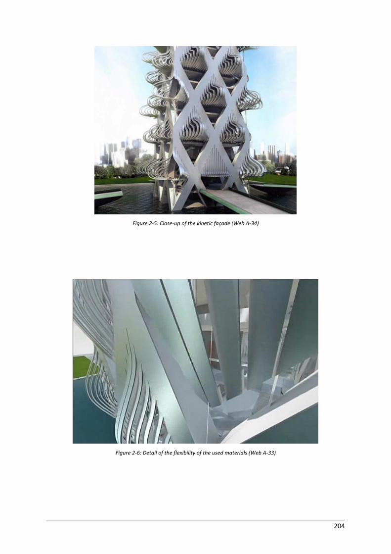
204
Figure 2-5: Close-up of the kinetic façade (Web A-34)
Figure 2-6: Detail of the flexibility of the used materials (Web A-33)
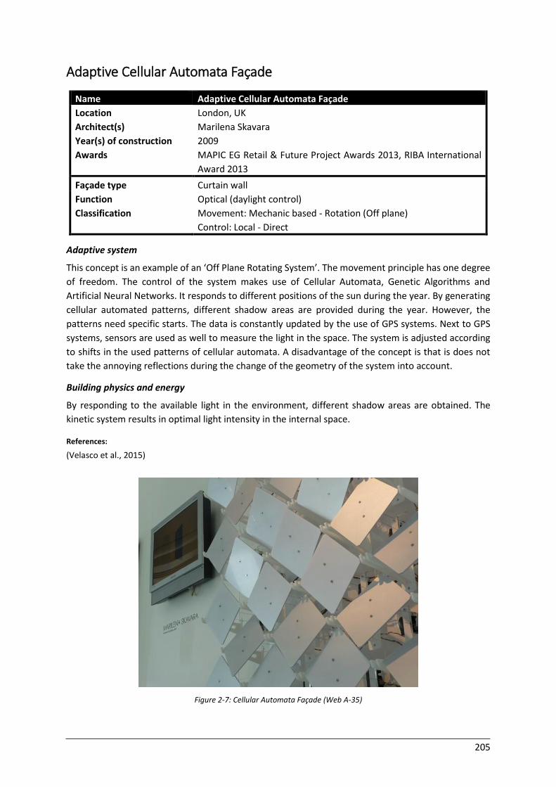
205
Adaptive Cellular Automata Façade
Name Adaptive Cellular Automata Façade
Location London, UK
Architect(s) Marilena Skavara
Year(s) of construction 2009
Awards MAPIC EG Retail & Future Project Awards 2013, RIBA International
Award 2013
Façade type Curtain wall
Function
Classification
Optical (daylight control)
Movement: Mechanic based - Rotation (Off plane)
Control: Local - Direct Adaptive system
This concept is an example of an ‘Off Plane Rotating System’. The movement principle has one degree
of freedom. The control of the system makes use of Cellular Automata, Genetic Algorithms and
Artificial Neural Networks. It responds to different positions of the sun during the year. By generating
cellular automated patterns, different shadow areas are provided during the year. However, the
patterns need specific starts. The data is constantly updated by the use of GPS systems. Next to GPS
systems, sensors are used as well to measure the light in the space. The system is adjusted according
to shifts in the used patterns of cellular automata. A disadvantage of the concept is that is does not
take the annoying reflections during the change of the geometry of the system into account.
Building physics and energy
By responding to the available light in the environment, different shadow areas are obtained. The
kinetic system results in optimal light intensity in the internal space.
References:
(Velasco et al., 2015)
Figure 2-7: Cellular Automata Façade (Web A-35)
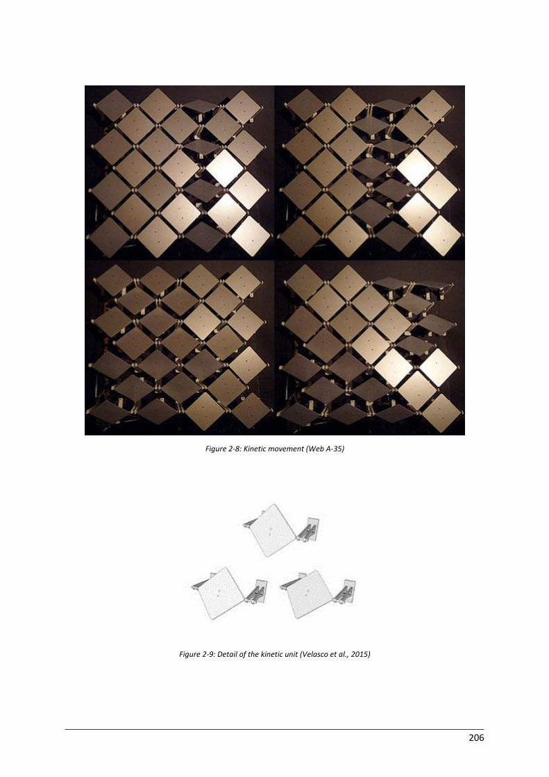
206
Figure 2-8: Kinetic movement (Web A-35)
Figure 2-9: Detail of the kinetic unit (Velasco et al., 2015)
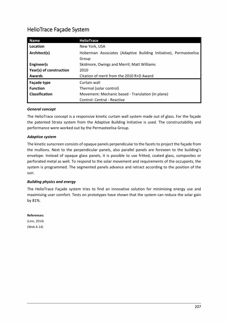
207
HelioTrace Façade System
Name HelioTrace
Location New York, USA
Architect(s) Hoberman Associates (Adaptive Building Initiative), Permasteelisa
Group
Engineer(s Skidmore, Owings and Merril; Matt Williams
Year(s) of construction 2010
Awards Citation of merit from the 2010 R+D Award
Façade type Curtain wall
Function
Classification
Thermal (solar control)
Movement: Mechanic based - Translation (In plane)
Control: Central - Reactive General concept
The HelioTrace concept is a responsive kinetic curtain wall system made out of glass. For the façade
the patented Strata system from the Adaptive Building Initiative is used. The constructability and
performance were worked out by the Permasteelisa Group.
Adaptive system
The kinetic sunscreen consists of opaque panels perpendicular to the facets to project the façade from
the mullions. Next to the perpendicular panels, also parallel panels are foreseen to the building’s
envelope. Instead of opaque glass panels, it is possible to use fritted, coated glass, composites or
perforated metal as well. To respond to the solar movement and requirements of the occupants, the
system is programmed. The segmented panels advance and retract according to the position of the
sun.
Building physics and energy
The HelioTrace Façade system tries to find an innovative solution for minimising energy use and
maximising user comfort. Tests on prototypes have shown that the system can reduce the solar gain
by 81%.
References:
(Linn, 2014)
(Web A-14)
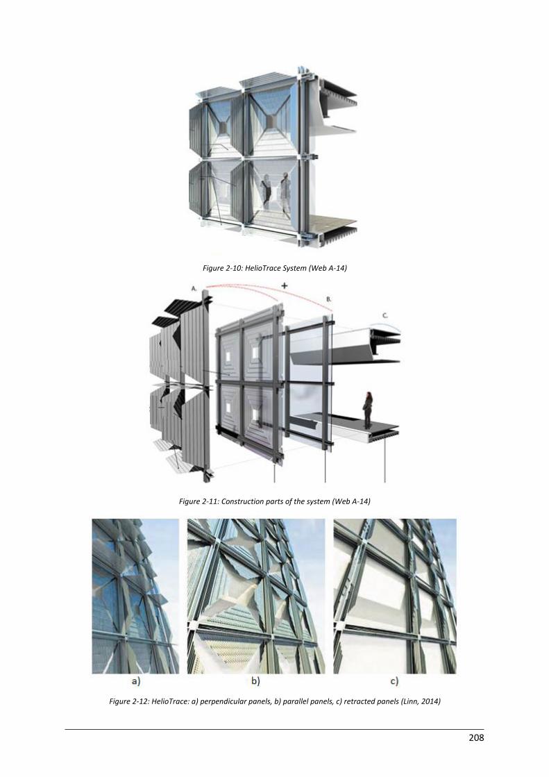
208
Figure 2-10: HelioTrace System (Web A-14)
Figure 2-11: Construction parts of the system (Web A-14)
Figure 2-12: HelioTrace: a) perpendicular panels, b) parallel panels, c) retracted panels (Linn, 2014)
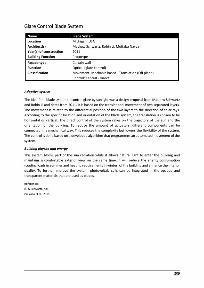
209
Glare Control Blade System
Name Blade System
Location Michigan, USA
Architect(s) Mathew Schwartz, Robin Li, Mojtaba Navva
Year(s) of construction 2011
Building Function Prototype
Façade type Curtain wall
Function
Classification
Optical (glare control)
Movement: Mechanic based - Translation (Off plane)
Control: Central - Direct
Adaptive system
The idea for a blade system to control glare by sunlight was a design proposal from Mathew Schwartz
and Robin Li and dates from 2011. It is based on the translational movement of two separated layers.
The movement is related to the differential position of the two layers to the direction of solar rays.
According to the specific location and orientation of the blade system, the translation is chosen to be
horizontal or vertical. The direct control of the system relies on the trajectory of the sun and the
orientation of the building. To reduce the amount of actuators, different components can be
connected in a mechanical way. This reduces the complexity but lowers the flexibility of the system.
The control is done based on a developed algorithm that programmes an automated movement of the
system.
Building physics and energy
This system blocks part of the sun radiation while it allows natural light to enter the building and
maintains a comfortable exterior view on the same time. It will reduce the energy consumption
(cooling loads in summer and heating requirements in winter) of the building and enhance the interior
quality. To further improve the system, photovoltaic cells can be integrated in the opaque and
transparent materials that are used as blades.
References:
(Li & Schwartz, n.d.)
(Velasco et al., 2015)
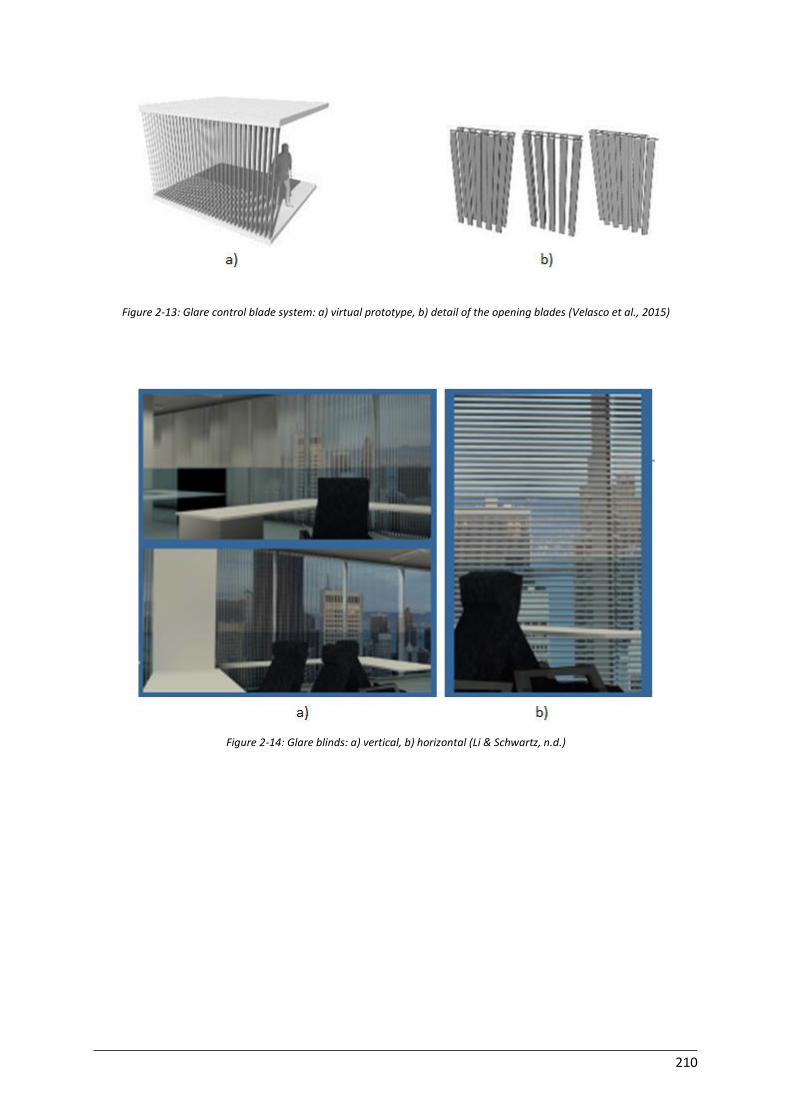
210
Figure 2-13: Glare control blade system: a) virtual prototype, b) detail of the opening blades (Velasco et al., 2015)
Figure 2-14: Glare blinds: a) vertical, b) horizontal (Li & Schwartz, n.d.)
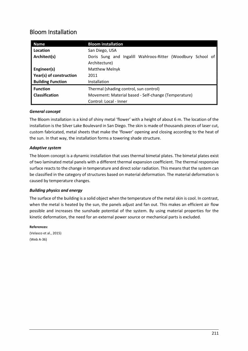
211
Bloom Installation
Name Bloom installation
Location San Diego, USA
Architect(s) Doris Sung and Ingalill Wahlroos-Ritter (Woodbury School of
Architecture)
Engineer(s) Matthew Melnyk
Year(s) of construction 2011
Building Function Installation
Function
Classification
Thermal (shading control, sun control)
Movement: Material based - Self-change (Temperature)
Control: Local - Inner General concept
The Bloom installation is a kind of shiny metal ‘flower’ with a height of about 6 m. The location of the
installation is the Silver Lake Boulevard in San Diego. The skin is made of thousands pieces of laser cut,
custom fabricated, metal sheets that make the ‘flower’ opening and closing according to the heat of
the sun. In that way, the installation forms a towering shade structure.
Adaptive system
The bloom concept is a dynamic installation that uses thermal bimetal plates. The bimetal plates exist
of two laminated metal panels with a different thermal expansion coefficient. The thermal responsive
surface reacts to the change in temperature and direct solar radiation. This means that the system can
be classified in the category of structures based on material deformation. The material deformation is
caused by temperature changes.
Building physics and energy
The surface of the building is a solid object when the temperature of the metal skin is cool. In contrast,
when the metal is heated by the sun, the panels adjust and fan out. This makes an efficient air flow
possible and increases the sunshade potential of the system. By using material properties for the
kinetic deformation, the need for an external power source or mechanical parts is excluded.
References:
(Velasco et al., 2015)
(Web A-36)

212
Figure 2-15: Bloom installation: a) global view, b) detail (Web A-36)
Figure 2-16: Material based deformation (Web A-30)
Figure 2-17: Visual effect from inside (Web A-37)
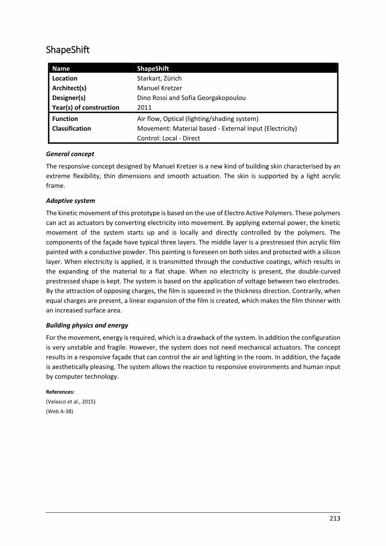
213
ShapeShift
Name ShapeShift
Location Starkart, Zürich
Architect(s) Manuel Kretzer
Designer(s) Dino Rossi and Sofia Georgakopoulou
Year(s) of construction 2011
Function
Classification
Air flow, Optical (lighting/shading system)
Movement: Material based - External Input (Electricity)
Control: Local - Direct General concept
The responsive concept designed by Manuel Kretzer is a new kind of building skin characterised by an
extreme flexibility, thin dimensions and smooth actuation. The skin is supported by a light acrylic
frame.
Adaptive system
The kinetic movement of this prototype is based on the use of Electro Active Polymers. These polymers
can act as actuators by converting electricity into movement. By applying external power, the kinetic
movement of the system starts up and is locally and directly controlled by the polymers. The
components of the façade have typical three layers. The middle layer is a prestressed thin acrylic film
painted with a conductive powder. This painting is foreseen on both sides and protected with a silicon
layer. When electricity is applied, it is transmitted through the conductive coatings, which results in
the expanding of the material to a flat shape. When no electricity is present, the double-curved
prestressed shape is kept. The system is based on the application of voltage between two electrodes.
By the attraction of opposing charges, the film is squeezed in the thickness direction. Contrarily, when
equal charges are present, a linear expansion of the film is created, which makes the film thinner with
an increased surface area.
Building physics and energy
For the movement, energy is required, which is a drawback of the system. In addition the configuration
is very unstable and fragile. However, the system does not need mechanical actuators. The concept
results in a responsive façade that can control the air and lighting in the room. In addition, the façade
is aesthetically pleasing. The system allows the reaction to responsive environments and human input
by computer technology.
References:
(Velasco et al., 2015)
(Web A-38)
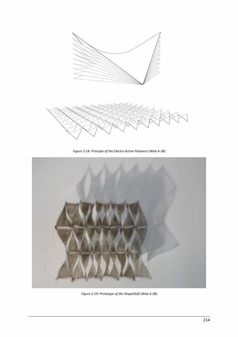
214
Figure 2-18: Principle of the Electro Active Polymers (Web A-38)
Figure 2-19: Prototype of the ShapeShift (Web A-38)
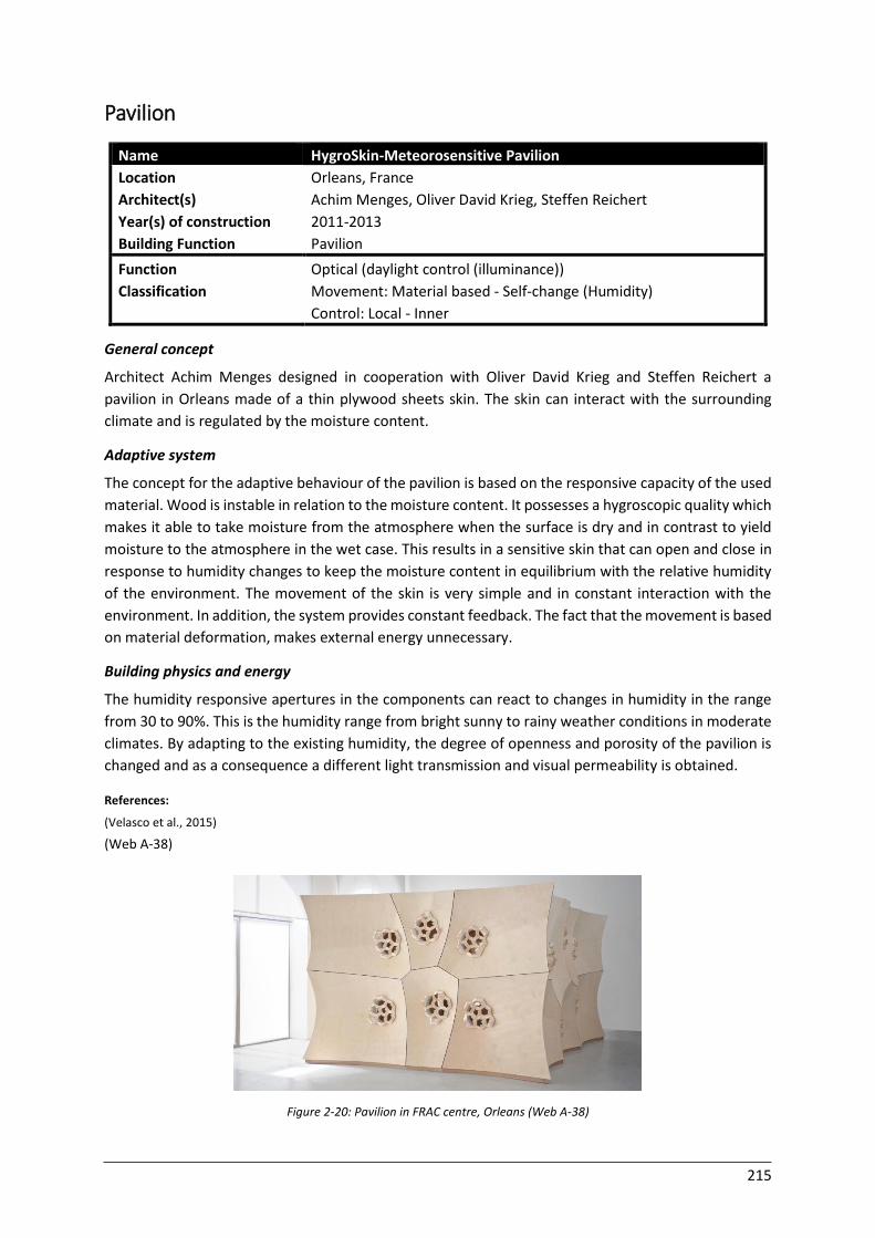
215
Pavilion
Name HygroSkin-Meteorosensitive Pavilion
Location Orleans, France
Architect(s) Achim Menges, Oliver David Krieg, Steffen Reichert
Year(s) of construction 2011-2013
Building Function Pavilion
Function
Classification
Optical (daylight control (illuminance))
Movement: Material based - Self-change (Humidity)
Control: Local - Inner General concept
Architect Achim Menges designed in cooperation with Oliver David Krieg and Steffen Reichert a
pavilion in Orleans made of a thin plywood sheets skin. The skin can interact with the surrounding
climate and is regulated by the moisture content.
Adaptive system
The concept for the adaptive behaviour of the pavilion is based on the responsive capacity of the used
material. Wood is instable in relation to the moisture content. It possesses a hygroscopic quality which
makes it able to take moisture from the atmosphere when the surface is dry and in contrast to yield
moisture to the atmosphere in the wet case. This results in a sensitive skin that can open and close in
response to humidity changes to keep the moisture content in equilibrium with the relative humidity
of the environment. The movement of the skin is very simple and in constant interaction with the
environment. In addition, the system provides constant feedback. The fact that the movement is based
on material deformation, makes external energy unnecessary.
Building physics and energy
The humidity responsive apertures in the components can react to changes in humidity in the range
from 30 to 90%. This is the humidity range from bright sunny to rainy weather conditions in moderate
climates. By adapting to the existing humidity, the degree of openness and porosity of the pavilion is
changed and as a consequence a different light transmission and visual permeability is obtained.
References:
(Velasco et al., 2015)
(Web A-38)
Figure 2-20: Pavilion in FRAC centre, Orleans (Web A-38)
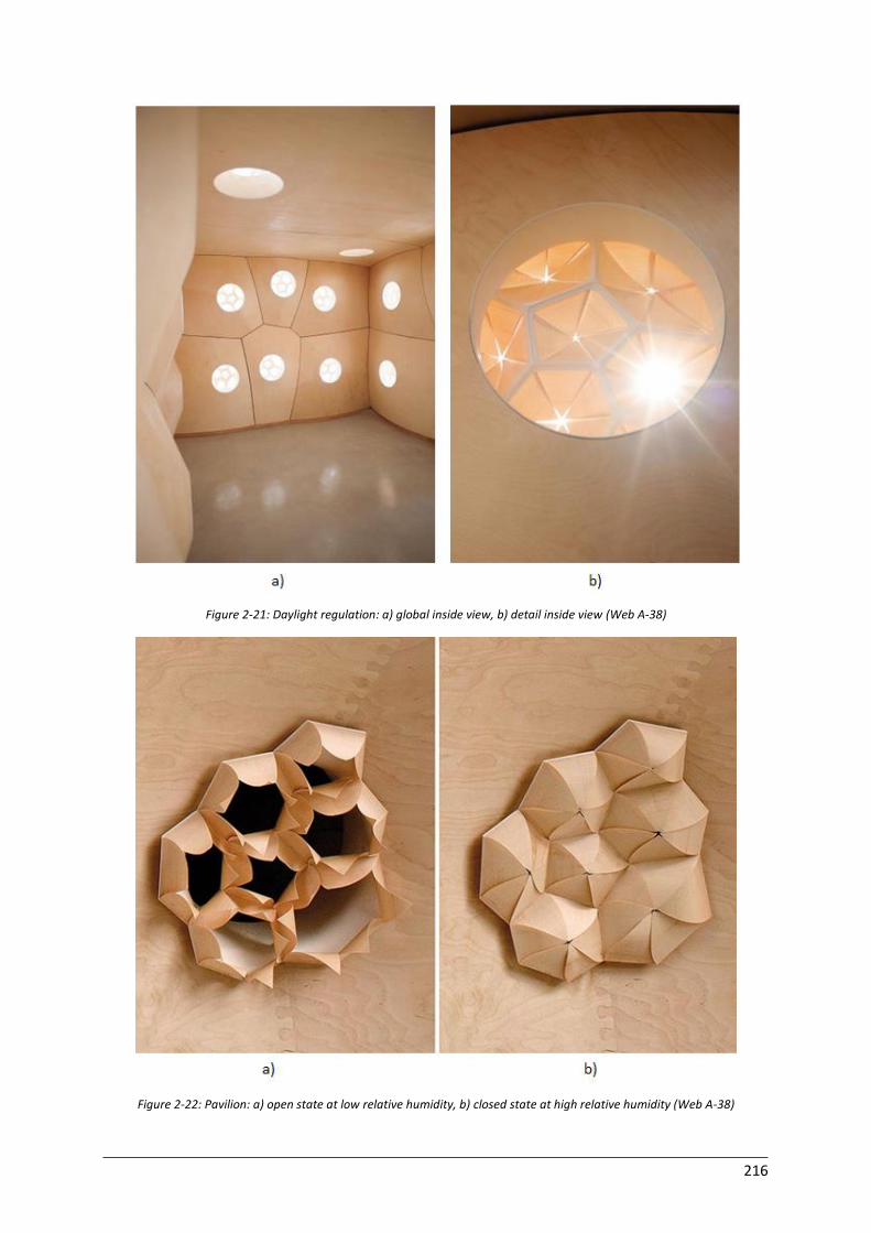
216
Figure 2-21: Daylight regulation: a) global inside view, b) detail inside view (Web A-38)
Figure 2-22: Pavilion: a) open state at low relative humidity, b) closed state at high relative humidity (Web A-38)
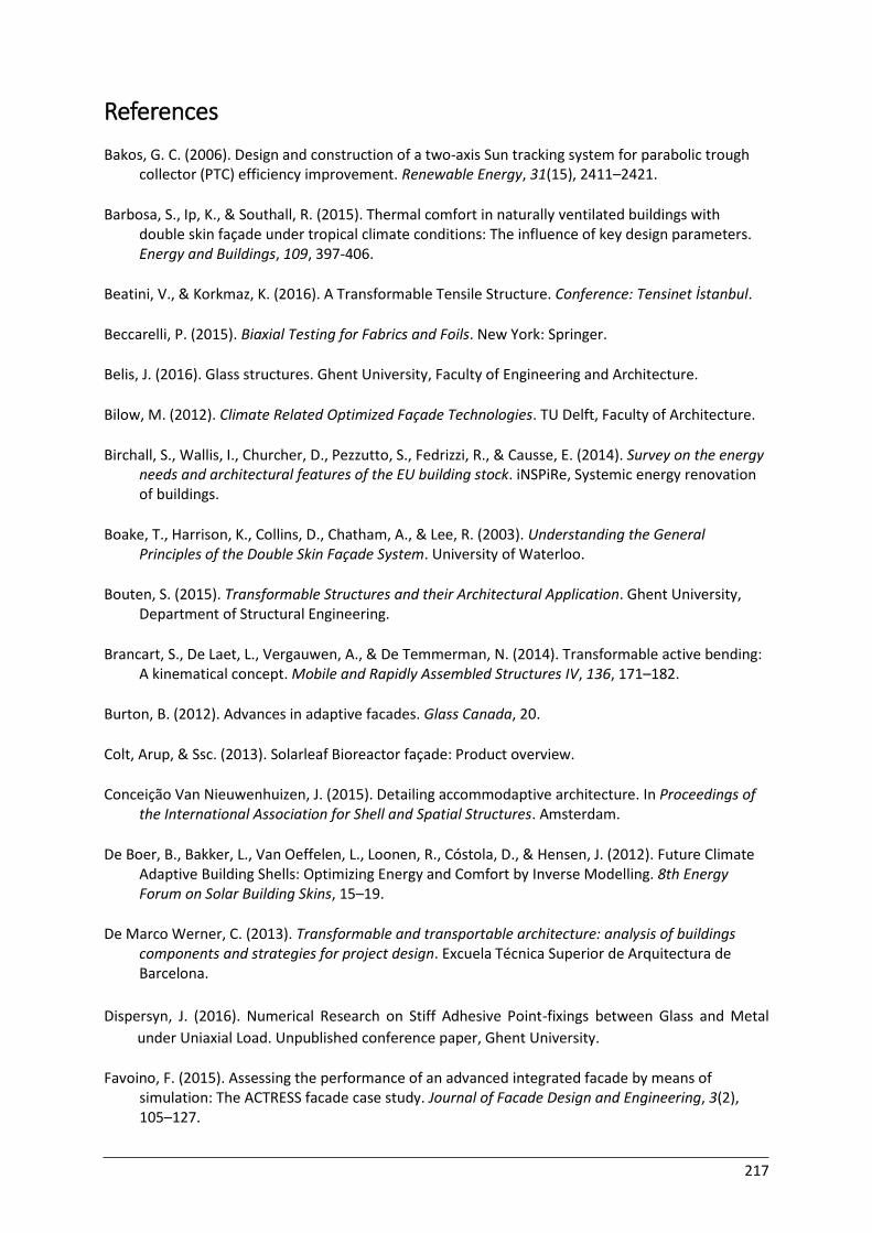
217
References
Bakos, G. C. (2006). Design and construction of a two-axis Sun tracking system for parabolic trough collector (PTC) efficiency improvement. Renewable Energy, 31(15), 2411–2421.
Barbosa, S., Ip, K., & Southall, R. (2015). Thermal comfort in naturally ventilated buildings with double skin façade under tropical climate conditions: The influence of key design parameters. Energy and Buildings, 109, 397-406.
Beatini, V., & Korkmaz, K. (2016). A Transformable Tensile Structure. Conference: Tensinet İstanbul.
Beccarelli, P. (2015). Biaxial Testing for Fabrics and Foils. New York: Springer.
Belis, J. (2016). Glass structures. Ghent University, Faculty of Engineering and Architecture.
Bilow, M. (2012). Climate Related Optimized Façade Technologies. TU Delft, Faculty of Architecture.
Birchall, S., Wallis, I., Churcher, D., Pezzutto, S., Fedrizzi, R., & Causse, E. (2014). Survey on the energy needs and architectural features of the EU building stock. iNSPiRe, Systemic energy renovation of buildings.
Boake, T., Harrison, K., Collins, D., Chatham, A., & Lee, R. (2003). Understanding the General Principles of the Double Skin Façade System. University of Waterloo.
Bouten, S. (2015). Transformable Structures and their Architectural Application. Ghent University, Department of Structural Engineering.
Brancart, S., De Laet, L., Vergauwen, A., & De Temmerman, N. (2014). Transformable active bending: A kinematical concept. Mobile and Rapidly Assembled Structures IV, 136, 171–182.
Burton, B. (2012). Advances in adaptive facades. Glass Canada, 20.
Colt, Arup, & Ssc. (2013). Solarleaf Bioreactor façade: Product overview.
Conceição Van Nieuwenhuizen, J. (2015). Detailing accommodaptive architecture. In Proceedings of the International Association for Shell and Spatial Structures. Amsterdam.
De Boer, B., Bakker, L., Van Oeffelen, L., Loonen, R., Cóstola, D., & Hensen, J. (2012). Future Climate Adaptive Building Shells: Optimizing Energy and Comfort by Inverse Modelling. 8th Energy Forum on Solar Building Skins, 15–19.
De Marco Werner, C. (2013). Transformable and transportable architecture: analysis of buildings components and strategies for project design. Excuela Técnica Superior de Arquitectura de Barcelona.
Dispersyn, J. (2016). Numerical Research on Stiff Adhesive Point-fixings between Glass and Metal
under Uniaxial Load. Unpublished conference paper, Ghent University.
Favoino, F. (2015). Assessing the performance of an advanced integrated facade by means of simulation: The ACTRESS facade case study. Journal of Facade Design and Engineering, 3(2), 105–127.
218
Feng, J. (2015). Mechanical Behavior of a Foldable Cable-strut Structure. In Proceedings of the International Association for Shell and Spatial Structures. Amsterdam.
González, S., & Carrasco, J. (2015). Ori-ssors : research processes in between vegetal crease patterns, expandable scissors and miura-ori solutions . In Proceedings of the International Association for Shell and Spatial Structures. Amsterdam.
Gordon, J. M., & Wenger, H. J. (1991). Central-Station Solar Photovoltaic Systems : sensitivity studies. Solar Energy, 46(4), 211–217.
Grynning, S., Time, B., & Matusiak, B. (2014). Solar shading control strategies in cold climates: Heating, cooling demand and daylight availability in office spaces. Solar Energy, 107, 182–194.
Guest, S. D., & Fowler, P. W. (2005). A symmetry-extended mobility rule. Mechanism and Machine Theory, 40(9), 1002–1014.
Haase, M., & Amato, A. (2009). An investigation of the potential for natural ventilation and building orientation to achieve thermal comfort in warm and humid climates. Solar Energy, 83(3), 389–399.
Hachem, C., Athienitis, A., & Fazio, P. (2014). Design of Curtain Wall Facades for Improved Solar Potential and Daylight Distribution. Energy Procedia, 57, 1815–1824.
Hachem, C., & Hanaor, A. (2006). Deployable Applications Based on Biological Organisms. Journal of the International Association for Shell and Spatial Structures, 95–106.
Haldimann, M., Luible, A. & Overend M. (2008). Structural use of glass (Vol. 10). International Association for Bridge and Structural Engineering.
Hanaor, A., & Levy, R. (2001). Evaluation of Deployable Structures for Space Enclosures. International Journal of Space Structures, 16(4), 211–229.
Hinge, A., Bertoldi, P., & Waide, P. (2004). Comparing Commercial Building Energy Use Around the World. Summer Study on Energy Efficiency in Buildings, 136–147.
Hoberman, C., & Schwitter, C. (2008). Adaptive Structures: Building for Performance and Sustainability. Design Intelligence.
Huld, T., Cebecauer, T., & Dunlop, E. (2008). Optimal mounting strategy for single-axis tracking non-concentrating PV in Europe. In Proceedings of the 23rd European Photovoltaic Solar Energy Conference and Exhibition. Valencia.
Huveners, E. M. P., Van Herwijnen, F., Soetens, F., & Hofmeyer, H. (2007). Glass panes acting as shear wall. Heron, 52(1/2), 5–29.
Ibáñez-Puy, M., Sacristán Fernández, J. A., Martín-Gómez, C., & Vidaurre-Arbizu, M. (2015). Development and construction of a thermoelectric active facade module. Journal of Facade Design and Engineering, 3(1), 15–25.
Industrial Perforators Association (1993). Designers, Specifiers And Buyers Handbook For Perforated Metals. Milwaukee.
219
Jelle, B., Breivik, C., & Røkenes, H. D. (2012). Building integrated photovoltaic products: A state-of-the-art review and future research opportunities. Solar Energy Materials and Solar Cells, 100, 69–96.
Jeska, S. (2008). Transparent Plastics: design and technology. Basel: Birkhäuser.
Jung, H., Kim, Y., & Kim, S. (2015). A Study on Transformable Facade Design Using Scissors system. In Proceedings of the International Association for Shell and Spatial Structures. Amsterdam.
Kaiser, T. J. (n.d.). Photovoltaic Engineering Module Experiments. Montana State University, Electrical and Computer Engineering.
Karanouh, A., & Kerber, E. (2015). Innovations in dynamic architecture. Journal of Facade Design and Engineering, 3(2), 185–221.
Kassem, M., & Mitchell, D. (2015). Bridging the gap between selection decisions of facade systems at the early design phase: Issues, challenges and solutions. Journal of Facade Design and Engineering, 3(2), 165–183.
Kirkegaard, P. H. (2011). Development and Evaluation of a Responsive Building Envelope. In International Adaptive Architecture Conference. London.
Klein, T. (2013). Integral Facade Construction: Towards a new product architecture for curtain walls. Technische Universiteit Delft.
Knaack, U., Klein, T., Bilow, M., & Auer, T. (2007). Façades: Principles of Construction. Basel: Birkhäuser.
Kolarevic, B., & Parlac, V. (2015). Building dynamics: Exploring architecture of change. London:
Routledge.
Lee, E., Selkowitz, S., Inkarojrit, V., & Kohler, C. (2002). High-Performance Commercial Building Façades. University of California.
Li, R., Dai, Y. J., & Wang, R. Z. (2015). Experimental and theoretical analysis on thermal performance of solar thermal curtain wall in building envelope. Energy and Buildings, 87, 324–334.
Li, R., & Schwartz, M. (n.d.). Dynamic Visualization and Simulation of Vertical And Horizontal Integrated Glare Control Blade System.
Li, Z., Liu, X., & Tang, R. (2010). Optical performance of inclined south-north single-axis tracked solar panels. Energy, 35(6), 2511–2516.
Liapi, K. A. (2002). Transformable Architecture Inspired by the Origami Art: Computer Visualization as a Tool for Form Exploration. Proceedings of the 2002 Annual Conference of the Association for Computer Aided Design In Architecture, 381–388.
Lienhard, J., Schleicher, S., Poppinga, S., Masselter, T., Milwich, M., Speck, T., & Knippers, J. (2011). Flectofin: a hingeless flapping mechanism inspired by nature. Bioinspiration & Biomimetics, 6(4).

220
Linn, C. (2014). Kinetic Architecture: Design for Active Envelopes. Mulgrave: Images Publishing Group.
Loonen, R. (2010). Climate Adaptive Building Shells. What can we simulate? Technische Universiteit Eindhoven, Faculty of Architecture, Building & Planning.
Loonen, R., Trčka, M., Cóstola, D., & Hensen, J. (2013). Climate adaptive building shells: State-of-the-art and future challenges. Renewable and Sustainable Energy Reviews, 25, 483–493.
López, M., Rubio, R., Martín, S., Croxford, B., & Jackson, R. (2015). Active materials for adaptive architectural envelopes based on plant adaptation principles. Journal of Facade Design and Engineering, 3(1), 27–38.
Lorenzo, E., Pérez, M., Ezpeleta, A., & Acedo, J. (2002). Design of tracking photovoltaic systems with a single vertical axis. Progress in Photovoltaics: Research and Applications, 10(8), 533–543.
Lovel, J. (2013). Building Envelopes: An integrated approach. New York: Princeton Architectural Press.
Martinez, R. (2013). Model for a green energy autonomous office building. Journal of Chemical Information and Modeling, 53(9), 1689–1699.
Mehrtash, M., Quesada, G., Dutil, Y., & Rousse, D. (2012). Performance Evaluation of Sun Tracking Photovoltaic Systems in Canada. In 20th Annual international Conference on mechanical Engineering (pp. 18–21). Shiraz.
Möller, E., & Nungesser, H. (2015). Adaptable Architecture by Frei Otto: a case study on the future viability of his visions and some forward ideas. In Proceedings of the International Association for Shell and Spatial Structures. Amsterdam.
Muhammad, L. B. (2010). Systematic Evaluation of Curtain Wall Types. Eastern Mediterranean University, Department of Architecture.
NBN EN 1990 (2002): Basis of structural design. Brussel: Bureau voor Normalisatie.
NBN EN 1991-1-1 (2002): Actions on structures - Part 1-1: General actions - Densities, self-weight,
imposed loads for buildings. Brussel: Bureau voor Normalisatie.
NBN EN 1991-1-3 (2003): Actions on structures - Part 1-3: General actions - Snow loads. Brussel:
Bureau voor Normalisatie.
NBN EN 1991-1-4 (2005): Actions on structures - Part 1-4: General actions - Wind actions. Brussel:
Bureau voor Normalisatie.
NBN EN 1993-1-1 (2005): Design of steel structures - Part 1-1: General rules and rules for buildings.
Brussel: Bureau voor Normalisatie.
NBN EN 1999-1-1 (2007): Design of aluminium structures - Part 1-1: General structural rules. Brussel:
Bureau voor Normalisatie.
221
Ogwezi, B., Jeronimidis, G., Cook, G., Sakula, J., & Gupta, S. (2012). Adaptive buildings’ facades for thermal comfort in hot-humid climates. In 3rd Annual TSBE EngD Conference. Henley Business School.
Ohsaki, M., Miyazu, Y., Tomoda, S., & Tsuda, S. (2015). Design of deployable structures using limit analysis of partially rigid frames with quadratic yield functions. In Proceedings of the International Association for Shell and Spatial Structures. Amsterdam.
Panico, D., Garvison, P., Wenger, H., & Shugar, D. (1991). Backtracking: a novel strategy for tracking PV systems. In Photovoltaic Specialists Conference, Conference Record of the Twenty Second IEEE (pp. 668-673). Las Vegas.
Pérez, G., Rincón, L., Vila, A., González, J. M., & Cabeza, L. F. (2011). Green vertical systems for buildings as passive systems for energy savings. Applied Energy, 88(12), 4854–4859.
Perino, M., & Serra, V. (2015). Switching from static to adaptable and dynamic building envelopes: A paradigm shift for the energy efficiency in buildings. Journal of Facade Design and Engineering, 3(2), 143–163.
Poirazis, H. (2004). Double Skin Façades for Office Buildings Literature Review. Lund University: Department of Contruction and Architecture, Division of Energy and Building.
Premier, A. (2015). Dynamic and Adaptive Surfaces on Tall Buildings. In Proceedings of the International Scientifical Conference (Vol. III). Venice.
Rand, B. P., Genoe, J., Heremans, P., & Poortmans, J. (2007). Comparison of Potential Solar Electricity Output from Fixed-Inclined and Two-Axis Tracking Photovoltaic Modules in Europe. Progress in Photovoltaics: Research and Applications, 16, 47–59.
Richards, P., & Robinson, M. (1999). Wind loads on porous structures. Journal of Wind Engineering and Industrial Aerodynamics, 83(1-3), 455–465.
Schramme, K., Boegle, A., & Gonzalez, J. M. O. (2015). The Challenge of Rigid-Foldable Structures. In Proceedings of the International Association for Shell and Spatial Structures. Amsterdam.
Seaverson, E. (2009). Glass-Metal Curtain Walls. StructureTec Jounal, 1009.
Shan, R. (2014). Optimization for Heating, Cooling and Lighting Load in Building Façade Design. Energy Procedia, 57, 1716–1725.
Shih, N.-J., & Huang, Y.-S. (2001). An analysis and simulation of curtain wall reflection glare. Building and Environment, 36(5), 619–626.
Sommer, H. (2009). Project Management for Building Construction. Berlin: Springer.
Suralkar, R. (2011). Solar Responsive Kinetic Facade Shading Systems inspired by plant movements in nature. In Proceedings of Conference: People and Buildings. London.
Susam, G. (2013). A research on a reconfigurable hypar structure for architectural applications. Izmir Institute of Technology, Department of Architecture.
222
Takatsuka, M. (2015). 2D-extended deployable linked panels and its current works. In Proceedings of the International Association for Shell and Spatial Structures. Amsterdam.
Takatsuka, M., & Ohmori, H. (2011). 2D-deployable flat-panel structure. Journal of the International Association for Shell and Spatial Structures, 52(2), 109–120.
Temmerman, N., Roovers, K., Mira, L. A., & Vergauwen, A. (2013). Engineering Lightweight Transformable Structures. In International Conference on Adaptation and Movement in Architecture. Toronto.
Trautz, M., & Cierniak, S. (2011). Folds and Fold Plate Structures in Architecture and Engineering. RWTH Aachen, Structures and Structural Design.
Umweni, O. J., & Ianakiev, A. (2015). Modified transformable gear-hinge scissors mechanisms for adaptability. In Proceedings of the International Association for Shell and Spatial Structures. Amsterdam.
Van Den Wymelenberg, K. (2012). Patterns of occupant interaction with window blinds: A literature review. Energy and Buildings, 51, 165–176.
Van Dijk, R. (2009). Adaptables. Delft University of Technology.
Velasco, R., Brakke, A. P., & Chavarro, D. (2015). Computer-Aided Architectural Design Futures. The Next City - New Technologies and the Future of the Built Environment. Springer-Verlag Berlin Heidelberg, 527, 172–191.
Velikov, K., & Thun, G. (2013). Responsive Building Envelopes: Characteristics and Evolving Paradigms. Design and Construction of High Performance Homes, 75–92.
Vergauwen, A., Mira, L. A., Roovers, K., & De Temmerman, N. (2013). Parametric design of adaptive shading elements based on Curved-line Folding. In Proceedings of the First Conference Transformables (pp. 337–342). Sevilla.
Vergauwen, A., De Temmerman, N., & Brancart, S. (2014). The design and physical modelling of deployable structures based on curved-line folding. Mobile and Rapidly Assembled Structures IV, 136, 145–155.
Weller, B., Hemmerle, C., Jakubetz, S., & Unnewehr, S. (2010). Photovoltaics: Technology, Architecture,
Installation. Basel: Birkhäuser.
223
Websites
Web 2-01: http://www.smia-experimental.com (Accessed on 27/09/2015)
Web 2-02: http://www.chattravieso.com (Accessed 27/09/2015)
Web 2-03: http://www.iri.upc.edu (Accessed on 29/11/2015)
Web 2-04: http://asmedigitalcollection.asme.org (Accessed on 27/09/2015)
Web 2-05: https://tensegritygoesblob.files.wordpress.com/ (Accessed on 30/11/2015)
Web 2-06: http://archinect.com/people/project// (Accessed on 1/11/2015)
Web 3-01:
http://www.sapagroup.com/Companies/Sapa%20Building%20System%20AB/Pictures/produkter/OL
D_GB/Tab_D_40-41.pdf (Accessed on 17/10/2015)
Web 3-02: http://planetfacts.org (Accessed on 25/10/2015)
Web 3-03: https://www.wbdg.org/resources/bipv.php (Accessed on 17/10/2015)
Web 3-04: http://www.enclos.com/service-and-technology/technology/acoustical-performance
(Accessed on 17/10/2015)
Web 3-05: http://kirosinak.info/curtain-drawing-wall/ (Accessed on 5/12/2015)
Web 3-06: http://www.wbdg.org (Accessed on 26/09/2015)
Web 3-07: http://www.academia.edu/3437899/Pros_and_Cons_of_Double_Skin_Envelope_Systems
(Accessed on 18/10/2015)
Web 3-08: http://www.wbdg.org/design/env_fenestration_cw.php (Accessed on 29/10/2015)
Web 3-09: http://www.dowcorning.com (Accessed on 29/10/2015)
Web 3-10: https://en.wikipedia.org/wiki/Curtain_wall_(architecture) (Accessed on 18/10/2015)
Web 3-11: http://www.glassmagazine.com (Accessed on 27/10/2015)
Web 3-12: http://www.onyxsolar.com (Accessed on 27/10/2015)
Web 3-13: http://www.fenestrapro.com (Accessed on 18/10/2015)
Web 3-14: https://en.wikipedia.org/wiki/Koppen_climate_classification (Accessed on 29/10/2015)
Web 3-15: http://www.sbd.ulg.ac.be/academic/BioclimaticDesign/Lecture%2003.html (Accessed on
5/12/2015)
Web 4-01: http://www.hoberman.com (Accessed on 13/09/2015)
Web 4-02: http://www.designingbuildings.co.uk/wiki/Home (Accessed on 25/09/2015)
Web 4-03: http://www.growinggreenguide.org/technical-guide/introduction-to-roofs-walls-and-
façades/green-façade-definition/ (Accessed on 26/10/2015)
Web 4-04: http://newscenter.lbl.gov/2009/06/02/working-toward-the-very-low-energy-
consumption-building-of-the-future/ (Accessed on 29/11/2015)
Web 4-05: https://en.wikipedia.org/wiki/Climate_adaptive_building_shell (Accessed on 8/10/2015)
Web 4-06: http://www.ongreening.com/it/Resources/SMART-MATERIALS-EXPLAINED-74 (Accessed
on 2/11/2015)
Web 5-01: http://www.seia.org/policy/solar-technology/photovoltaic-solar-electric (Accessed on
08/02/2016)
Web 5-02: http://www.solarstik.com/stikopedia/solar-stiktm-system-overview/choosing-power-
generators/amorphous-vs-cigs (Accessed on 10/02/2016)
Web 5-03: http://energyinformative.org/ (Accessed on 10/02/2016)
Web 5-04: http://www.gonewiththewynns.com/flexible-rv-solar-issues-review (Accessed on
9/02/2016)
224
Web 5-05: http://www.strathconasolar.com/single-axis-vs-dual-axis-solar-tracking/ (Accessed on
16/02/2016)
Web 5-06:
http://www.centralsemi.com/content/product/applications/alt_energy/solar_bypass_diode.php24
(Accessed on 24/02/2016)
Web 5-07: http://ec.europa.eu/oib/pdf/mit-standard-building-specs_en.pdf (Accessed on
24/02/2016)
Web 5-08: http://www.homepower.com/articles/solar-electricity/equipment-
products/understanding-pv-module-specifications (Accessed on 2/03/2016)
Web 5-09: http://www.lumossolar.com/products/lsx-module-system/ (Accessed on 16/03/2016)
Web 5-10: http://www.nextgenerationsolar.com/ (Accessed on 10/03/2016)
Web 5-11: https://nl.wikipedia.org/wiki/Lijst_van_hoogste_gebouwen_van_Belgi%C3%AB (Accessed
on 10/03/2016)
Web 5-12: http://educationcenter.ppg.com/glasstopics/resist_wind_snow_loads.aspx (Accessed on
14/03/2016)
Web 6-01: http://openbuildings.com/ (Accessed on 12/04/2016)
Web 6-02: http://www.dezeen.com (Accessed on 12/04/2016)
Web 6-03: http://accurateperforating.com (Accessed on 8/04/2016)
Web 6-04: http://www.nultylighting.co.uk/ (Accessed on 19/04/2016)
Web 6-05: http://www.polytronixglass.com/ (Accessed on 8/04/2016)
Web 6-06: http://www.steelwindows.com (Accessed on 8/04/2016)
Web 6-07: http://www.globalsources.com (Accessed on 16/04/2016)
Web 6-08: http://www.apw.co.uk/ (Accessed on 17/04/2016)
Web 6-09: http://diamondscreens.com/ (Accessed on 16/04/2016)
Web 6-10: https://www.bifold.com/ (Accessed on 14/04/2016)
Web 6-11: http://www.cascadedepot.com/90-degree-locking-hinge/ (Accessed on 14/04/2016)
Web 6-12: http://www.usglasspro.com/swing-door/ (Accessed on 16/04/2016)
Web 6-13: http://www.namdaran.ir/ (Accessed on 24/04/2016)
Web 6-14: http://www.dowcorning.com/ (Accessed on 28/04/2016)
Web A-01: http://en.wikiarquitectura.com/index.php/Arab_World_Institute (Accessed on
4/10/2015)
Web A-02: http://focal-glow.tumblr.com/post/institut-du-monde-arabe-in-paris (Accessed on
14/10/2015)
Web A-03: http://filt3rs.net/case/art-paper-museum-moving-façade-shigeru-ban-049 (Accessed on
10/10/2015)
Web A-04: http://filt3rs.net/case/double-skin-façade-agbar-tower-barcelona-jean-nouvel-226
(Accessed on 21/10/2015)
Web A-05: https://en.wikipedia.org/wiki/Torre_Agbar (Accessed on 21/10/2015)
Web A-06: http://www.pvdatabase.org (Accessed on 10/10/2015)
Web A-07: http://www.coltgroup.com (Accessed on 10/10/2015)
Web A-08: http://www.asp-stuttgart.de (Accessed on 10/10/2015)
Web A-09: http://www.archdaily.com/89270/kiefer-technic-showroom-ernst-giselbrecht-partner
(Accessed on 12/10/2015)
225
Web A-10: http://www.e-architect.co.uk/austria/kiefer-technic-showroom (Accessed on
12/10/2015)
Web A-11: http://www.designboom.com (Accessed on 12/10/2015)
Web A-12: http://ming3d.com/DAAP/ARCH713fall11/?author=8 (Accessed on 12/10/2015)
Web A-13: http://www.nikken.jp/en/projects/retail/pola-ginza-building.html (Accessed on
12/10/2015)
Web A-14: http://www.hoberman.com (Accessed on 12/10/2015)
Web A-15: http://www.openbuildings.com (Accessed on 12/10/2015)
Web A-16: http://façadesconfidential.blogspot.be/2010/12/thyssenkrupp-quarter-façades-
giants.html (Accessed on 10/10/2015)
Web A-17: http://www.archdaily.com/326747/q1-thyssenkrupp-quarter-essen-jswd-architekten-
chaix-morel-et-associes (Accessed on 10/10/2015)
Web A-18: http://www.archdaily.com/123791/sebrae-headquarters-gruposp (Accessed on
10/10/2015)
Web A-19: http://www.inhabitat.com (Accessed on 10/10/2015)
Web A-20: http://www.designingfortomorrow.org (Accessed on 10/10/2015)
Web A-21: http://www.archdaily.com/123791/sebrae-headquarters-gruposp/ (Accessed on
10/10/2015)
Web A-22: http://www.achimmenges.net/?p=5612 (Accessed on 10/10/2015)
Web A-23: http://www.arup.com (Accessed on 10/10/2015)
Web A-24: http://skyscrapercentre.com/abu-dhabi/al-bahar-tower-2/9130/ (Accessed on
10/10/2015)
Web A-25: http://www.archdaily.com/270592/al-bahar-towers-responsive-façade-aedas (Accessed
on 10/10/2015)
Web A-26: http://www.archdaily.com/265508/west-18th-street-oda (Accessed on 11/10/2015)
Web A-27: http://www.evolo.us/architecture/cj-research-centres-kinetic-folding-façade-yazdani-
studio/ (Accessed on 12/10/2015)
Web A-28: https://yazdanistudioresearch.wordpress.com/2011/11/15/cj-rd-centre-kinetic-façade/
(Accessed on 12/10/2015)
Web A-29: http://www.archdaily.com/236979/one-ocean-thematic-pavilion-expo-2012-soma
(Accessed on 12/10/2015)
Web A-30: http://www.archdaily.com/ (Accessed on 23/10/2015)
Web A-31: http://www.rex-ny.com/mhq/ (Accessed on 23/10/2015)
Web A-32: http://hilo.arch.ethz.ch/?page_id=90 (Accessed on 11/10/2015)
Web A-33: http://www.evolo.us/architecture/kinetower-is-a-metamorphic-skyscraper-kinetura/
(Accessed on 12/10/2015)
Web A-34: https://www.nextnature.net/2011/04/kinetic-architecture/ (Accessed on 12/10/2015)
Web A-35: http://www.designboom.com (Accessed on 12/10/2015)
Web A-36: http://www.emanate.org/past-exhibitions/2015/6/19/bloom (Accessed on 30/10/2015)
Web A-37: http://archinew.altervista.org//(Accessed on 30/10/2015)
Web A-38: http://www.achimmenges.net/ (Accessed on 5/11/2012)

226
Software programs used for modelling
Autodesk (2014): Autocad 2014
http://www.autodesk.com
MathWorks (2014): Matlab R2014b
http://www.athena.ugent.be
McNeel R. (2015): Grasshopper Generative Modelling with Rhino
Robert McNeel and associates, Seattle, WA, USA
McNeel R. (2015): Rhinoceros 3D, version 5.0
Robert McNeel and associates, Seattle, WA, USA
Nemetschek (2015): SCIA Engineer 15.3
http://www.nemetschek-SCIA.com
227
List of Figures
Figure 1: Panels: a) turning west, b) turning east ................................................................................... xii
Figure 2: Double principle: a) balcony, b) perforated screen ................................................................ xiii
Figure 3: Transformation principle: a) unfolding screen, b) opening windows .................................... xiii
Figure 2-1: Adaptive structures ............................................................................................................... 7
Figure 2-2: Hanaor classification system (Hanaor & Levy, 2001) ............................................................ 8
Figure 2-3: Basic scissor units: a) translational, b) polar and c) angulated (Web 2-01) ........................ 10
Figure 2-4: Deployment phases of a Jitterbug mechanism (Web 2-02) ................................................ 11
Figure 2-5: Bennett linkage: a) fully closed state, b) deploying state, c) forming a compact bundle of
bars (Guest & Fowler, 2005) ................................................................................................................. 12
Figure 2-6: Array central connection of Myard linkages (Bouten, 2015) .............................................. 12
Figure 2-7: Bricard linkage (Web 2-03).................................................................................................. 13
Figure 2-8: Wren platform: a) structure, b) skew legs, c) parallel legs (Bouten, 2015) ........................ 13
Figure 2-9: Sarrus linkage (Web 2-04) ................................................................................................... 14
Figure 2-10: Surface folding: a) longitudinal rigid, b) rigid facetted, c) longitudinal kinematic folding
(Trautz & Cierniak , 2011) ...................................................................................................................... 15
Figure 2-11: Folding motion of the most common patterns (Schramme et al., 2015) ......................... 16
Figure 2-12: Foldable strut-cable unit (Feng, 2015) .............................................................................. 18
Figure 2-13: Tensegrity creation (Web 2-05) ........................................................................................ 18
Figure 2-14: Curved-line folding based on a) one, b) two, c) three or d) four creases (Vergauwen et al.,
2013)...................................................................................................................................................... 19
Figure 2-15: Tensioned membrane structure (Hanaor & Levy, 2001) .................................................. 20
Figure 2-16: Pneumatic structure (Web 2-06) ...................................................................................... 20
Figure 2-17: Deployment phases of Ori-ssors (González & Carrasco, 2015) ......................................... 21
Figure 2-18: 2D-deployable flat-panel structures (Takatsuka & Ohmori, 2011) ................................... 22
Figure 3-1: Functional requirements façade (Adapted from Web 3-01) .............................................. 27
Figure 3-2: Solar trajectory (Web 3-02) ................................................................................................. 29
Figure 3-3: Solar control systems: a) exterior, b) spectrally selective, c) angular selective, d) solar filter
............................................................................................................................................................... 29
Figure 3-4: Types of façades: a) curtain wall façade and b) double façade (Knaack et al., 2007) ........ 33
Figure 3-5: Aluminium frame and glass infill panel (Web 3-05) ............................................................ 34
Figure 3-6: Overview curtain wall systems: a) stick, b) unitised, c) frameless (Klein, 2013) (Knaack et al.,
2007)...................................................................................................................................................... 35
Figure 3-7: Possible façade configurations stick system: a) post-and-beam, b) post, c) beam (Knaack et
al., 2014) ................................................................................................................................................ 36
Figure 3-8: Double façade types: a) second-skin, b) box-window, c) corridor, d) shaft-box (Knaack et al.,
2007)...................................................................................................................................................... 38
Figure 3-9: Principle of the double-skin façade: a) front view, b) side view (Web 3-07) ...................... 39
Figure 3-10: Principle box-window façade (side view) (Web 3-07) ......…………………………………………….40
Figure 3-11: Example of a box-window façade (Klein, 2013) ................................................................ 40
Figure 3-12: Principle corridor façade (front view) (Web 3-07) ………………………………………………….……40
Figure 3-13: Example of a corridor façade (Klein, 2013) ....................................................................... 40
Figure 3-14: Principle of shaft-box façade: a) front view, b) side view (Web 3-07) .............................. 41
Figure 3-15: Alternating façade (Knaack et al., 2007) ........................................................................... 41
Figure 3-16: Essential requirements ..................................................................................................... 43

228
Figure 3-17: Principle of the U-value (Web 3-09).................................................................................. 45
Figure 3-18: Insulated glass unit (Klein, 2013) ...................................................................................... 45
Figure 3-19: Comfort increasing functions ............................................................................................ 46
Figure 3-20: The five climate zones (Web 3-14) .................................................................................... 56
Figure 3-21: Temperature and precipitation of the climate zones (Van Dijk, 2009) ............................ 56
Figure 3-22: Sunshade analysis (Web 3-15) .......................................................................................... 58
Figure 3-23: Sustainable building .......................................................................................................... 61
Figure 4-1: Alternatives for 'Adaptive' .................................................................................................. 66
Figure 4-2: Façade regulation mechanisms ........................................................................................... 67
Figure 4-3: Types of dynamic interfaces: a) green façades, b) adaptive façades ................................. 69
Figure 4-4: Ecological footprint of buildings (Web 4-04) ...................................................................... 70
Figure 4-5: Position of the façade: a) in front, b) in the skin, c) behind (Sommer, 2010) ..................... 71
Figure 4-6: Level of adaption for a west façade (Van Dijk, 2009) ......................................................... 73
Figure 4-7: Proposal of new classification system (Adapted from (Velasco et al., 2015)) .................... 75
Figure 4-8: Overview movement of existing systems ........................................................................... 79
Figure 4-9: The four physical domains and overlap zones (Adapted from (Loonen, 2010)) ................. 81
Figure 4-10: Overview distribution of applications ............................................................................... 81
Figure 4-11: Flectofin principle: a) theoretical position of the wings, b) real position of the wings
pushing against each other, c)-e) opening of the wings due to bending of the backbone (Lienhard et
al., 2011) ................................................................................................................................................ 83
Figure 4-12: a) winged Dermaptera male, b) the hind wing of the Dermaptera, c) paper model
simulating folding of the fan part of the hind wing (Hachem & Hanaor, 2006) ................................... 83
Figure 5-1: Cosine relationship between angle of incidence and output power (Kaiser, n.d.) ............. 95
Figure 5-2: Annual array irradiation comparison (Mehrtash et al., 2012) ............................................ 96
Figure 5-3: Array irradiation on a clear day in winter (Mehrtash et al., 2012) ..................................... 96
Figure 5-4: Array irradiation on a clear day in summer (Mehrtash et al., 2012) .................................. 97
Figure 5-5: Optimum inclination angle (degrees inclination from horizontal) (Huld et al., 2008) ........ 98
Figure 5-6: Relative difference (in %) in solar radiation (Huld et al., 2008) .......................................... 98
Figure 5-7: Bypass diode principle for series cells (Web 5-06) ............................................................. 99
Figure 5-8: Demonstration GCR principle ........................................................................................... 100
Figure 5-9: Demonstration backtracking strategy (Panico et al., 1991) .............................................. 100
Figure 5-10: Solar elevation Angle in Belgium: a) Dec 21, b) June 21 ................................................. 101
Figure 5-11: Tracking angle (blue) for no backtracking on June 21 .................................................... 102
Figure 5-12: Tracking angle (blue) for no backtracking on Dec 21 ...................................................... 102
Figure 5-13: Tracking angle (blue) for backtracking over 45° and GCR 0.75 (June 21) ....................... 103
Figure 5-14: Tracking angle (blue) for backtracking over 45° and GCR 0.75 (Dec 21) ........................ 103
Figure 5-15: Distance x from the wall (front view) .............................................................................. 104
Figure 5-16: Lay-out panel positioning (side view) ............................................................................. 105
Figure 5-17: No shadow when faced south (top view cross-section) ................................................. 106
Figure 5-18: Illustration shadow area (30° turned east) (top view cross-section) .............................. 106
Figure 5-19: Illustration tracking principle: a) turning west, b) turning east ...................................... 107
Figure 5-20: Sketch pull-pull system ................................................................................................... 109
Figure 5-21: Pull at left side ................................................................................................................. 109
Figure 5-22: Pull at right side .............................................................................................................. 109
Figure 5-23: Pull-pull system ............................................................................................................... 110
Figure 5-24: Detail of the system: a) top view, b) side view ............................................................... 110
229
Figure 5-25: Sketch push-pull system.................................................................................................. 111
Figure 5-26: Pulling mode ................................................................................................................... 111
Figure 5-27: Pushing mode .................................................................................................................. 111
Figure 5-28: Gear wheel principle ....................................................................................................... 112
Figure 5-29: Push-pull model: a) side view, b) front view ................................................................... 112
Figure 5-30: Side view of panel and mounting system ....................................................................... 113
Figure 5-31: Example PV module (Web 5-10) ..................................................................................... 114
Figure 5-32: Wind force: a) pressure, b) suction ................................................................................. 117
Figure 5-33: Snow load ........................................................................................................................ 118
Figure 5-34: Six adhesive point fixings ................................................................................................ 119
Figure 5-35: Design situation ............................................................................................................... 120
Figure 5-36: Side view deformed glass panel ...................................................................................... 122
Figure 5-37: Top view displacements glass PV module ....................................................................... 123
Figure 5-38: Top view loaded glass PV module (x-direction stresses) ................................................ 124
Figure 5-39: Top view loaded glass PV module (y-direction stresses) ................................................ 124
Figure 5-40: Aluminium profile: a) basic, b) alternative ...................................................................... 125
Figure 5-41: Displacement aluminium turning tube ........................................................................... 126
Figure 5-42: Displacement steel cantilever ......................................................................................... 127
Figure 5-43: Finalisation lay-out .......................................................................................................... 127
Figure 5-44: Final lay-out (side view): a) with extension (drawing), b) without extension (virtual
prototype) ........................................................................................................................................... 128
Figure 5-45: Energy intensities for office buildings in various EU countries (Hinge et al., 2004) ....... 129
Figure 5-46: Energy production in kWh/m²/month (Photovoltaic Information System) ................... 130
Figure 5-47: Top view, panels faced south .......................................................................................... 132
Figure 5-48: Front view ....................................................................................................................... 133
Figure 5-49: Side view ......................................................................................................................... 133
Figure 5-50: Panels turning: a) 30° west, b) 30° east .......................................................................... 133
Figure 6-1: Perforated screen: a) view from outside, b) view from inside (Web 6-01; Web 6-02) .... 137
Figure 6-2: Prototype: a) folded, b) unfolded screen (closed windows), c) unfolded screen (opened
windows) ............................................................................................................................................. 138
Figure 6-3: Transformation principle: a) unfolding screen, b) opening windows ............................... 139
Figure 6-4: Prototype model: a) folded screen, b) unfolded balcony ................................................. 139
Figure 6-5: Opening principle screen: a) detailed side view, b) overall view ...................................... 140
Figure 6-6: Opening principle windows: a) front view, b) top view .................................................... 140
Figure 6-7: Tessellate principle (Web 6-04) ........................................................................................ 141
Figure 6-8: Assumed dimensions ........................................................................................................ 141
Figure 6-9: Glued glass-frame connection .......................................................................................... 144
Figure 6-10: Connection system: a) metal side projection, b) locked situation .................................. 144
Figure 6-11: Vertical opening: a) sliding window (Web 6-07), b) balcony illustration ........................ 145
Figure 6-12: Perforation patterns (Web 6-08) .................................................................................... 145
Figure 6-13: Mounting freedom: a) box in front, b) box behind ......................................................... 146
Figure 6-14: Detail piano hinges (Web 6-09)....................................................................................... 147
Figure 6-15: Hydraulic opening principle (Web 6-10) ......................................................................... 147
Figure 6-16: 90° locking hinge (Web 6-11) .......................................................................................... 148
Figure 6-17: Principle window opening (Web 6-12) ............................................................................ 148
Figure 6-18: Model opened balcony SCIA ........................................................................................... 150
230
Figure 6-19: Illustration perforation ratio (Web 6-13) ........................................................................ 151
Figure 6-20: Properties perforated screen: a) yield strength, b) elastic properties (Industrial Perforators
Association, 1993) ............................................................................................................................... 151
Figure 6-21: Downward displacement: a) side view, b) top view ....................................................... 154
Figure 6-22: Horizontal displacement parapet.................................................................................... 155
Figure 6-23: Downward displacement frame (side view): a) without glass pane, b) with glass pane 156
Figure 6-24: Prototype II - widened perforated screen ...................................................................... 158
Figure 6-25: Prototype II - conventional façade and sliding window .................................................. 158
Figure 1-1: Façade of the Arab World Institute (Web A-01)................................................................ 165
Figure 1-2: Details (a-b) of the opening system (Web A-02) ............................................................... 165
Figure 1-3: Diaphragm system: a) real design, b-c) virtual drawings (Velasco et al., 2015) ............... 165
Figure 1-4: Museum of paper art: a-c) closed façades, d-f) opened façades (Web A-03) ................... 167
Figure 1-5: Overview of the different façades (Simone, 2005) ………………………………………………………….167
Figure 1-6: Detail of the system (Web A-03) ....................................................................................... 167
Figure 1-7: Nocturnal spectacle (Web A-04) …………………………………………………………………….................169
Figure 1-8: Detail of pivoting blinds (Web A-04) ................................................................................. 169
Figure 1-9: Detail of the double-skin façade (Web A-04) ………………………………………………………………..169
Figure 1-10: Ground plan (Web A-04) ……………………………………………………………………………………………..169
Figure 1-11: Detail of the system (Weller et al., 2010) ……………………………………………………………………..171
Figure 1-12: Details of photovoltaic panel (Web A-08) ....................................................................... 171
Figure 1-13: Controllable solar shading (Web A-07) ........................................................................... 171
Figure 1-14: Kiefer Technic Showroom (Web A-09) ……………………………………………………………………….. 172
Figure 1-15: Detail of the façade (Web A-11) ………………………………………………………………………………….172
Figure 1-16: Façade of the Pola Ginza Building: a-b) outside view, c-d) inside view (Web A-14) ....... 174
Figure 1-17: Rotating element: a) front view, b) upper view (Web A-15) ........................................... 174
Figure 1-18: Twisting fins (Web A-16) ................................................................................................. 176
Figure 1-19: Façade view (Web A-17) ................................................................................................. 176
Figure 1-20: ThyssenKrupp Headquarters (Web A-17) ........................................................................ 177
Figure 1-21: Detail of the movement of the fins (Web A-16) .............................................................. 177
Figure 1-22: Turning according to position of the sun (Web A-17) ..................................................... 177
Figure 1-23: Sebrae headquarters (Web A-18) .................................................................................... 179
Figure 1-24: Inside atrium (Web A-19) ................................................................................................ 179
Figure 1-25: Brise-soleil cladding (Web A-20) …………………………………………………………………………………179
Figure 1-26: Brise-soleil cladding (from outside) (Web A-21) ............................................................. 179
Figure 1-27: Media ICT-building (Web A-22) ....................................................................................... 181
Figure 1-28: Air cushions (Web A-22) ……………………………………………………………………………………………..181
Figure 1-29: Detail of the inflating cushions (Web A-22) .................................................................... 181
Figure 1-30: Roof structure (Web A-14) .............................................................................................. 183
Figure 1-31: Daylight control (Web A-14) ........................................................................................... 183
Figure 1-32: Planar kinetic system: a) real design, b-c) virtual drawings (Velasco et al., 2015) ......... 183
Figure 1-33: Audiencia Provincial atrium (Web A-14) ......................................................................... 185
Figure 1-34: Strata system: a) opened slats, b) opening slats, c) retracted slats (Web A-14) ............ 185
Figure 1-35: Roof position: a) retracted, b) sun tracking (Web A-14) ................................................. 185
Figure 1-36: Abu Dhabi investment council (Web A-24) ..................................................................... 188
Figure 1-37: Unit in: a) closed position, b) opening position, c) opened position (Web A-23) ............ 188
Figure 1-38: Shading system Investment council Abu Dhabi (Karanouh & Kerber, 2015) .................. 188
231
Figure 1-39: Construct detail (leaflet CTBUH Innovation Award, 2012) .............................................. 189
Figure 1-40: Inside view of the curtain wall system (Karanouh & Kerber, 2015) ................................ 189
Figure 1-41: Different views (a-c) of the façade of West 18th Street (Web A-26) .............................. 190
Figure 1-42: CJ R&D centre (Web A-28) ............................................................................................... 192
Figure 1-43: Folding system with scissors (Web A-28) ........................................................................ 192
Figure 1-44: Kinetic folding façade (Web A-27) .................................................................................. 193
Figure 1-45: Top view of the research centre (Web A-27) ................................................................... 193
Figure 1-46: The kinetic light façade (Web A-29) ................................................................................ 195
Figure 1-47: Movement of the lamellas (Web A-29) ........................................................................... 195
Figure 1-48: Opening of the lamellas (Web A-29) ............................................................................... 196
Figure 1-49: Lamellas in the façade (Web A-29) ................................................................................. 196
Figure 1-50: Overview of the building site (Web A-30) …………………………………………………………………….198
Figure 1-51: Umbrella-like shading system (Web A-30) ..… ................................................................ 198
Figure 1-52: Umbrella in opened position (Web A-30) …………………………………………………………………….198
Figure 1-53: Opening of the umbrella (Web A-30) …………………………………………………………………………..198
Figure 1-54: Umbrella completely retracted in the cavity (Web A-30) ……………………………………………..198
Figure 1-55: Covering of courtyards (Web A-30) ................................................................................. 198
Figure 1-56: Solarleaf façade: a) front view, b) detail of two panels (Colt et al., 2013) ..................... 200
Figure 1-57: Detail of the solarleaf façade (Colt et al., 2013) ............................................................. 200
Figure 2-1: Prototype Solar Façade (Web A-32) .................................................................................. 201
Figure 2-2: Basic module (Web A-32) .................................................................................................. 202
Figure 2-3: Prototype (Web A-32) ....................................................................................................... 202
Figure 2-4: Kinetower: a) closed position, b) opened position (Premier, 2015) .................................. 203
Figure 2-5: Close-up of the kinetic façade (Web A-34) ........................................................................ 204
Figure 2-6: Detail of the flexibility of the used materials (Web A-33) ................................................. 204
Figure 2-7: Cellular Automata Façade (Web A-35) ............................................................................. 205
Figure 2-8: Kinetic movement (Web A-35) .......................................................................................... 206
Figure 2-9: Detail of the kinetic unit (Velasco et al., 2015) ................................................................. 206
Figure 2-10: HelioTrace System (Web A-14) ........................................................................................ 208
Figure 2-11: Construction parts of the system (Web A-14) ................................................................. 208
Figure 2-12: HelioTrace: a) perpendicular panels, b) parallel panels, c) retracted panels (Linn, 2014)
............................................................................................................................................................. 208
Figure 2-13: Glare control blade system: a) virtual prototype, b) detail of the opening blades (Velasco
et al., 2015).......................................................................................................................................... 210
Figure 2-14: Glare blinds: a) vertical, b) horizontal (Li & Schwartz, n.d.) ............................................ 210
Figure 2-15: Bloom installation: a) global view, b) detail (Web A-36) ................................................ 212
Figure 2-16: Material based deformation (Web A-30) ........................................................................ 212
Figure 2-17: Visual effect from inside (Web A-37) .............................................................................. 212
Figure 2-18: Principle of the Electro Active Polymers (Web A-38) ....................................................... 214
Figure 2-19: Prototype of the ShapeShift (Web A-38) ......................................................................... 214
Figure 2-20: Pavilion in FRAC centre, Orleans (Web A-38) .................................................................. 215
Figure 2-21: Daylight regulation: a) global inside view, b) detail inside view (Web A-38).................. 216
Figure 2-22: Pavilion: a) open state at low relative humidity, b) closed state at high relative humidity
(Web A-38) .......................................................................................................................................... 216
232
List of Tables
Table 2-1: Overview transformable structures ....................................................................................... 9
Table 3-1: Stick system vs Unitised system ........................................................................................... 37
Table 3-2: Advantages and disadvantages of curtain wall façades ....................................................... 48
Table 3-3: Advantages and disadvantages of double façades .............................................................. 51
Table 3-4: Overview diagram for façade types and functions .............................................................. 52
Table 3-5: Comparison of the different orientations (Van Dijk, 2009) ................................................. 54
Table 3-6: Characteristics for each climate zone (Adapted from (Bilow, 2012)) .................................. 59
Table 4-1: Mechanical components and their function (Adapted from (Van Dijk, 2009)) .................... 76
Table 4-2: Smart materials and their function ...................................................................................... 77
Table 5-1: Case definition ...................................................................................................................... 88
Table 5-2: Overview design aspects ...................................................................................................... 89
Table 5-3: Comparison rigid and flexible panels (Based on (Jelle et al., 2012)) .................................... 91
Table 5-4: Comparison crystalline silicon PV panels (Based on Web 5-03) .......................................... 91
Table 5-5: Comparison thin film panels (Based on Web 5-03) .............................................................. 92
Table 5-6: Comparison cell efficiency - cost (Based on (Jelle et al., 2012)) .......................................... 92
Table 5-7: Degradation rate (Adapted from Web 5-03) ........................................................................ 93
Table 5-8: Comparison solar tracking systems ...................................................................................... 95
Table 5-9: Results optimisation parameters panel ............................................................................. 105
Table 5-10: Shadow comparison ......................................................................................................... 108
Table 5-11: PV module specification (Web 5-08) ................................................................................ 113
Table 5-12: Safety factors .................................................................................................................... 120
Table 5-13: Stress check in aluminium cross-section .......................................................................... 125
Table 5-14: Stress check clamp connection 1 ..................................................................................... 126
Table 5-15: Stress check clamp connection 2 ..................................................................................... 126
Table 5-16: Optimisation lay-out ......................................................................................................... 128
Table 6-1: Case definition .................................................................................................................... 136
Table 6-2: Overview design aspects .................................................................................................... 136
Table 6-3: Recommended ranges for the dimensions ........................................................................ 142
Table 6-4: Parameters wind calculation .............................................................................................. 149
Table 6-5: Overview wind forces ......................................................................................................... 149
Table 6-6: Service loads ....................................................................................................................... 150
Table 6-7: Self-weight .......................................................................................................................... 152
Table 6-8: Stresses in the steel plates ................................................................................................. 153
Table 6-9: Stresses in the steel frame and glass pane ........................................................................ 155