Stronger at Depth: Jamming Grippers as Deep Sea Sampling Tools
27
University of Rhode Island DigitalCommons@URI Civil & Environmental Engineering Faculty Publications Civil & Environmental Engineering 2017 Stronger at Depth: Jamming Grippers as Deep Sea Sampling Tools Stephen Licht University of Rhode Island, [email protected] Evere Collins See next page for additional authors Follow this and additional works at: hps://digitalcommons.uri.edu/cve_facpubs e University of Rhode Island Faculty have made this article openly available. Please let us know how Open Access to this research benefits you. is is a pre-publication author manuscript of the final, published article. Terms of Use is article is made available under the terms and conditions applicable towards Open Access Policy Articles, as set forth in our Terms of Use. is Article is brought to you for free and open access by the Civil & Environmental Engineering at DigitalCommons@URI. It has been accepted for inclusion in Civil & Environmental Engineering Faculty Publications by an authorized administrator of DigitalCommons@URI. For more information, please contact [email protected]. Citation/Publisher Aribution Licht, S., Evere, C., Lopes, M. M., & Christopher, B.(2017). Stronger at Depth: Jamming Grippers as Deep Sea Sampling Tools. Soſt Robotics. 4(4), 305-316. doi: 10.1089/soro.2017.0028 Available at: hps://doi.org/10.1089/soro.2017.0028
Transcript of Stronger at Depth: Jamming Grippers as Deep Sea Sampling Tools
University of Rhode IslandDigitalCommons@URICivil & Environmental Engineering FacultyPublications Civil & Environmental Engineering
2017
Stronger at Depth: Jamming Grippers as Deep SeaSampling ToolsStephen LichtUniversity of Rhode Island, [email protected]
Everett Collins
See next page for additional authors
Follow this and additional works at: https://digitalcommons.uri.edu/cve_facpubs
The University of Rhode Island Faculty have made this article openly available.Please let us know how Open Access to this research benefits you.
This is a pre-publication author manuscript of the final, published article.
Terms of UseThis article is made available under the terms and conditions applicable towards Open Access PolicyArticles, as set forth in our Terms of Use.
This Article is brought to you for free and open access by the Civil & Environmental Engineering at DigitalCommons@URI. It has been accepted forinclusion in Civil & Environmental Engineering Faculty Publications by an authorized administrator of DigitalCommons@URI. For more information,please contact [email protected].
Citation/Publisher AttributionLicht, S., Everett, C., Lopes, M. M., & Christopher, B.(2017). Stronger at Depth: Jamming Grippers as Deep Sea Sampling Tools. SoftRobotics. 4(4), 305-316. doi: 10.1089/soro.2017.0028Available at: https://doi.org/10.1089/soro.2017.0028

AuthorsStephen Licht, Everett Collins, Emmanuel Lopes Mendes, and Christopher Baxter
This article is available at DigitalCommons@URI: https://digitalcommons.uri.edu/cve_facpubs/8
Stronger at Depth: Jamming Grippers as Deep Sea Sampling Tools
Abstract— In this work we experimentally demonstrate (a) that the holding strength of universal jamming grippers
increases as a function of the jamming pressure to greater than three atmospheres, and (b) that jamming grippers can be
used for deep sea grasping tasks in ambient pressures exceeding one hundred atmospheres, where such high jamming
pressures can be readily achieved. Laboratory experiments in a pressurized, water filled test cell are used to measure the
holding force of a 'universal' style jamming gripper as a function of the pressure difference between internal membrane
pressure and ambient pressure. Experiments at sea are used to demonstrate that jamming grippers can be installed on,
and operated from, remotely operated vehicles (ROVs) at depths in excess of 1200m. In both experiments, the jamming
gripper consists of a latex balloon filled with a mixture of fresh water and ~200 micron glass beads, which are cheaply
available in large quantities as sand blasting media. The use of a liquid, rather than gas, as the fluid media allows
operation of the gripper with a closed loop fluid system; jamming pressure is controlled with an electrically driven water
hydraulic cylinder in the lab, and with an oil hydraulic driven large-bore water hydraulic cylinder at sea.
Keywords—soft robotics; compliant grippers; universal jamming gripper; underwater manipulation; remotely operated
vehicles.
I. INTRODUCTION
Robotic sampling of fragile and irregularly shaped objects is often a critical component of deep sea biological and
archaeological investigations. The current state of the art for underwater sampling is the use of one or two
manipulators with multiple rigid links and rigid end-effectors driven with high pressure oil hydraulics. Even with
highly skilled pilots, collecting samples at any reasonably complex site with an ROV is difficult and time consuming.
It is not atypical for a >2000kg robot with a potential grip closure strength of >1000N to be used to sample objects
with a weight of only a few grams in water. The fundamental danger in these sampling tasks is that a rigid gripper on
a non-back drivable arm could make unintended contact with a priceless, fragile object with a huge amount of
momentum driving the gripper and the arm. Soft robotics are attractive in large part because their inherently
compliant structures can passively eliminate accidental shock loading on sampled objects.
For the present study, we use a 'universal' particle jamming gripper. Particle jamming is accomplished by creating
a pressure differential between the inside of a particle filled flexible membrane and the fluid surrounding the
membrane [1]. When the flexible membrane is filled with fluid at the same pressure of the surrounding fluid, the
membrane does not obstruct the motion of the particles inside. The particles can move around each other freely, and
the membrane is free to take the shape of any object that it is pressed against. To make the membrane harden in its
current shape, fluid is removed from the inside of the membrane. The grains inside are jammed together by the
membrane, which constricts under the external pressure. The grains can no longer flow around each other and the
whole mass becomes rigid.
A universal jamming gripper uses a single elastic membrane filled with particles, where the membrane is
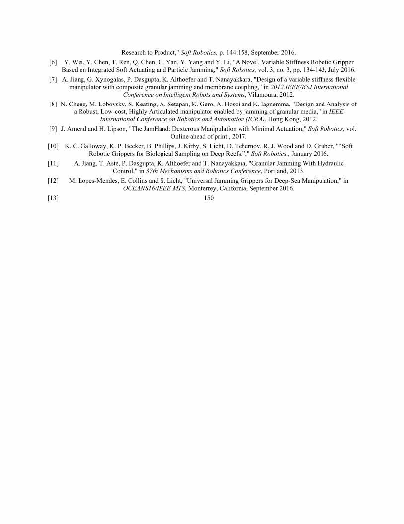
suspended below a rigid disc or shallow cup [1]. As shown in Figure 1, the membrane is lowered onto the object to be
grasped, fluid is pumped out to jam the particles together, and the object can then be picked up along with the gripper.
The performance of universal jamming grippers has been a topic of extensive quantitative characterization in air [2]
[3] [4]. It has been commercialized for factory automation Empire Robotics, albeit not yet successfully [5]. Particle
jamming has also been proposed and demonstrated in a wide variety of more mechanically complex manipulation
applications including, e.g. control of joint stiffness and 2-DOF actuation in pneumatically actuated fingers [6, 7],
articulated motion in an octopus like manipulator arm [8], two degree motion in and in a multi-fingered hand [9]. We
have chosen to focus on the universal gripper as a test case for jamming grippers at depth for reasons of simplicity
and robustness.
Soft robotics is particularly attractive in underwater applications because soft components can have densities close
to that of the surrounding fluid. When operated underwater, soft robotics can use liquid, rather than gas, within the
internal fluid circuits without making the robot too heavy to support itself. Indeed, an incompressible liquid is
required to avoid the use of high pressure gas reservoirs and attendant regulation apparatus which would otherwise be
needed to compensate for pressure at depth. The feasibility of using water for both pressure compensation and fluid
actuation has been demonstrated at depths greater than 500m with fiber reinforced finger-like actuators [10]. A further
benefit of using liquid, as noted in [11] is that it allows the use of a low volume closed-circuit fluid system to control
particle jamming, however this was proposed as a means of creating compact terrestrial vehicles. Liquid water as a
medium for jamming in a submerged universal gripper was first described in [12] where various objects were
recovered from the bottom of a 4m deep fresh water tank.
Intriguingly, [1] hypothesized that the strength of the grasp of a universal jamming gripper should be linear
function of the vacuum pressure with respect to the ambient air, particularly for the case where an interlocking grasp
was achieved on a sample. The mechanism postulated was an increase in the shear strength of the jammed mass as the
jamming pressure increases. Given that the jamming pressure is limited by the absolute ambient pressure, and that
ambient pressure increases with water depth, a particle jamming based gripper should increase in strength as it is
carried deeper in the water column, making it an attractive choice as a deepwater tool.
The experiments described below were performed to test the hypotheses that (a) the maximum lifting force that
can be achieved by a universal jamming gripper is dependent on the jamming pressure, i.e. the pressure drop across
the confining membrane between ambient and internal; that (b) this increase in gripper performance occurs when the
ambient and interstitial internal fluid consists of liquid water; and that (c) the force continues to increase for jamming
pressures greater than one atmosphere.
II. METHODS
Our goal in developing underwater soft gripper technologies is to support deep water archaeological and
biological sampling, particularly deep water intervention tasks using remotely operated vehicles (ROVs) tethered to a
surface ship. Our target platform is the scientific work class ROV Hercules, pictured in Figure 2, which can be
operated to depths of up to 4000m from the dedicated 64-m support ship E/V Nautilus1. The ROV pilots aboard the
surface ship communicate with and command the actuators and sensors onboard the ROV via the tether. The ROV
Hercules uses electric power transmitted over the tether to drive onboard systems, including a 15-kW rated hydraulic
pressure unit (HPU) capable of supply pressures up to 3000psi. A Kraft PredatorTM 7-DOF hydraulic arm with a rigid
pincer end-effecter is used for all physical sampling tasks. Samples are either grasped directly with the end-effecter,
or acquired using tools that can be picked up by the end effecter from the ROV 'front porch'. The Kraft arm uses joint
fluid pressure to transmit force information to the pilot's control joystick, however pilots are justifiably reluctant to
rely on the rigid end-effecter to grasp potentially priceless, non-renewable cultural artifacts. In this effort, we focus on
a 'universal' style jamming gripper which can be picked up and applied by the rigid end-effecter, as shown in Figure
3.
The gripper design includes a linear bearing, which limits the maximum vertical force applied to any sample to the
in-water weight of the gripper itself. A closed-circuit hydraulic system converts high-pressure, low volume oil
hydraulics to low-pressure, high volume water hydraulics through an in-line cylinder pair. A schematic showing the
design of the gripper membrane, manifold, cap, and handle is shown in Figure 4. The fluid manifold is machined from
a 6061aluminum rod and connects a single inlet-outlet port from the side to an internal cavity bored out from the
bottom of the manifold. The bottom hole is covered with a filter (400x400 mesh stainless steel woven wire cloth) that
allows water flow but blocks the particles from entering the manifold. The manifold is inserted through the cap (3-D
printed in ABS using a Stratysys Dimension printer) and then in to the neck of a latex balloon (Qualatex 18" Diamond
Clear Round) that is partially filled with 94g of solid glass beads (Potters Ballotini® 212-300μ Impact Beads). The
average density of the bead material is 2.5g/cc, the average density of the packed beads is 1.66g/cc, and the uninflated
volume of the membrane is approximately 225cc. The beads are thus 25% of maximum amount that can be contained
without inflating the membrane. A blind threaded hole in the top of the cylinder is used to attach to the gripper handle
shaft of nominal 0.5in diameter ceramic-coated aluminum.
The fluid drive system consists of a 127mm bore stainless steel water filled cylinder (TRD Mfg., RS Series) and a
25mm bore oil filled cylinder (HydroLek 11060). The piston rods of the two cylinders are concentric and directly
connected end to end, as indicated in cross-section in Figure 4. A three-position four-way proportional valve, which is
integrated with an existing 1500psi oil-hydraulic system on-board the ROV, is used to control the high pressure
cylinder. The maximum jamming pressure across the jamming membrane is 58psi (3.95atm), resulting from the
hydraulic system pressure of 1500psi and the 26:1 area ratio of the two cylinders. The pilot controls the valve from
the surface through manual setting of the solenoid valve PWM duty cycle; fine control of jamming pressure was not
possible during the experiments described here due to the nearly 10 second latency in valve control and pressure
response. Jamming pressure was observed using an analog gauge pressure sensor (Thuemling SPAN series)
referenced to ambient pressure with a range of ±60psi (±414kPa). The installed locations on the ROV Hercules of the
gripper apparatus, the fluid drive system, the analog pressure gauge, all of which are connected using flexible thick
walled polyurethane tubing (1.8in ID, 3/8in OD), are indicated in Figure 5.
1 http://www.nautiluslive.org/tech
A linear bearing was used to enable the robot manipulator to apply full strength upwards while at the same time
passively limiting the downwards force applied to the in-water weight of the gripper apparatus. The gripper handle
shaft slides in the linear bearing, and is constrained in the downward direction by a shaft collar clamped around the
top of the shaft. In field operation, the robot manipulator grasps the apparatus via the outer bearing cylinder which
has a plain thrust bearing (Rulon J self-lubrciating PTFE) press fit into each end. Handling with the pincer
mechanism is made easier by the addition of two 2.5in (64mm) diameter rigid polyurethane ball handles to the
bearing cylinder, as shown in the image Figure 3, which gives the pilots view of operations when the ROV is at depth.
As illustrated in Figure 1, the weight of the gripper and its load are supported by the shaft collar when the gripper
is not in contact with the substrate. The arm is then lowered until the weight of the gripper is fully supported by the
sample and/or substrate. The pilot can see that this has occurred by observing when by the bearing cylinder begins
sliding down the shaft, thus losing contact with the shaft collar. Once the gripper is in contact, fluid is removed from
the membrane via the fluid inlet port, developing a pressure difference across the membrane and jamming the
particles.
For the deployed gripper, and for all experiments in this effort, the membrane was only partially filled with
particles. As described in [12] the partially filled membrane is able to drape around the objects that it is applied to,
and the weight of the freely flowing particles then forces the membrane to extend slightly underneath overhangs.
This shape promotes the gripping modality referred to in [1] as 'interlock', as opposed to the 'friction' and 'suction'
modes. The interlock mode is the mode that is most clearly dependent on the shear strength of the rigid gripper
shape, as the grip fails only with large scale shape changes. For the purposes of this effort, the primary effect of this
design choice is that the partially filled membrane achieves an effective interlocking grip without the need to shape
the membrane around the object, whether manually as in [1], or with some additional actuation step which would add
potentially unacceptable complexity to fielded operation.
One consequence of the use of a partially filled membrane is that there is a significant difference in the volume of
the membrane before and after the jamming step, as illustrated in Figure 1 (b)-(c). In order for the gripper to achieve
a high quality grasp on the object, it is critical that the apparatus be free to fall under its own weight and thus continue
to press down on the membrane as the fluid is removed. In previous work [12] this was accomplished by allowing the
cap to slide on the manifold, but pinching of the membrane between the cap and the manifold during the relative
motion was found to be a primary failure mode. For this effort, the membrane and cap move together as the bearing
shaft slides within the bearing cylinder. This proved to be a more reliable solution and made it possible to change the
total range of motion simply by increasing the shaft length.
III. EXPERIMENTAL APPARATUS: LABORATORY
As operational time at depth on a work class scientific ROV is extremely costly, the gripper design was
extensively tested using a triaxial load frame (GeoComp LoadTrac-II) with an integrated pressure chamber and flow
control system (GeoComp FlowTrac-II). The experimental apparatus is pictured in Figure 6. The pressure chamber is
an acrylic cylinder with gasket-sealed removable top and bottom caps. The pressure chamber is mounted rigidly to the
movable platen of the load frame. The platen can follow pre-programmed velocity or force profiles, where force is
measured using a single-axis S-beam load cell mounted to the load frame above the pressure chamber, and velocity is
measured using a spring loaded linear probe in contact with the platen.
The top cap of the pressure chamber contains a shaft penetration consisting of a linear bearing with a dynamic o-
ring seal. The gripper apparatus is contained inside the pressure chamber, supported from above by the gripper
handle, which passes through the shaft penetration. Two fluid inputs to the chamber, accessed through fittings in the
bottom cap, are connected externally to two independent FlowTrac-II systems, which consist of electrically driven
water hydraulic cylinders instrumented for pressure and volume control. One flow control system is plumbed directly
to the interior of the pressure chamber, and controls ambient chamber pressure. The other flow control system is
plumbed to a pass through, which is connected inside the chamber to a length of flexible tubing, which is in turn
connected to the manifold. The flexible tubing is arranged in a spiral configuration to minimize vertical forcing on the
gripper. The fluid circuits are isolated from one another and closed. All fluid used in these experiments is fresh water
at room temperature.
The manifold, cap, membrane, and beads tested are identical to those used at sea, however a longer handle shaft is
needed to provide sufficient length to protrude from the pressure chamber regardless of the gripper vertical position
relative to the chamber. Eyebolts are threaded in to the bottom of the S-beam load cell (Artech 20210 series, max.
load 11N) which is attached to the load frame above the chamber, and in to the top of the gripper handle shaft. A
weight tray is mounted to the lower shaft, allowing weight to be added to compensate for the vertical pressure force
resulting from chamber pressures which are higher than the ambient pressure in the laboratory. The pressure force is
proportional to this pressure differential and the internal cross-sectional area of the linear bearing.
The sample object in all tests is a 110mm long, 10mm diameter stainless steel tube. The sample was mounted
parallel to the surface of the aluminum base plate, with the lower surface held 6mm above the substrate with a 4-40
rod, which was threaded into a blind tapped hole in the center of the length. During all experiments the rigid cone of
the gripper apparatus makes contact with the ends of the sample rod. As a result, the entire weight of the gripper
apparatus rests on the sample, with the exception of some portion of the bead and membrane weight which is
supported by the substrate. The downward load on the sample is thus approximately equal to the in-water weight of
the gripper. This sample geometry was chosen to simplify estimates of the downwards force applied, eliminating the
need for a submersible force sensor to distinguish between loads applied to the sample and the substrate.
For each experiment, as shown in Figure 7, the gripper mechanism is allowed to come to rest on the sample before
jamming, and to settle on the sample during jamming, under the weight of the gripper mechanism, shaft, and weight
tray. Once the gripper is fully jammed, the shaft is connected to the load cell by a tension member, and the platen is
lowered until the jammed gripper loses contact with the sample. In this manner, we are able to measure the total
upwards force applied by the gripper to the sample, while ensuring that the downward force applied does not exceed
the total in water weight of the gripper and the handle, thus simulating operation at sea. Gripper holding force is
calculated as the difference between the maximum load recorded by the load cell, and the load recorded immediately
after all contact with the sample is lost, with the platen still in downward motion.
The two flow control systems are used to independently control pressure and flow inside the membrane and
surrounding the membrane. Throughout each experiment, the chamber pressure was regulated by injecting or
removing fluid using PID feedback control, with external piston volume as the control input. The volume of fluid
external to the membrane is directly tied to the total displacement of the gripper and the gripper support structure; thus
when fluid is added or removed from the membrane to control either membrane volume or membrane pressure, fluid
must be removed or added to the chamber to maintain pressure. Lowering or raising the gripper structure changes the
displacement of the gripper, as the shaft penetrates to different distances, again requiring fluid to be removed or
added.
The membrane fluid flow is used to regulate either volume or pressure depending on the current stage of the
grasping process. Prior to grasping, fluid is removed from the membrane in pressure regulation mode to achieve a
small (10kPa) difference between internal and external pressure, indicating the start of jamming. A controlled volume
of fluid is then injected in to the membrane to inflate it partially prior to application to the sample. This initial fluid
volume is one of the parameters varied in the experiments described below. All tests are performed with the starting
internal membrane pressure equal to the surrounding ambient pressure, as the balloon is never inflated to the point of
elastic stretching. Once the gripper is applied to the sample, the gripper is 'jammed' by removing fluid from the
membrane, regulating pressure to achieve the desired jamming pressure.
IV. LABORATORY EXPERIMENT: RESULTS
The gripper lifting force, FL, was recorded while varying four experimental parameters: system weight in water,
FW, ambient pressure, PA, jamming pressure, PJ, and initial membrane fluid volume VI. A series of 23 experiments
was performed.
Jamming pressure.
We recorded FL as a function of PJ=(30, 60, 85, 170, 255, 340) kPa with PA = 4 atm, FW = 5N, and VI =120mL.
As seen in Figure 8, FL increases more than three-fold, from 3.8N to 15.3N when PJ is increased from 30 to 85kPa.
FL doubles again to 29.9N when PJ is increased to 340kPa. The relationship is linear within the upper range; recorded
mean values with error bars representing variance are plotted against a linear fit to the experiments within this range,
where FL =0.057 x10⁻³ PJ + 10. There is a significant difference in sensitivity above and below PJ =85kPa, and the
linear fit to the lower range is FL =0.21 x10⁻³ PJ - 2.6.
Effects of ambient pressure.
To determine sensitivity of FL to ambient pressure, three experiments were performedat reduced ambient
pressures for a subset of the jamming pressures above,: PJ=85kPa at 1atm, and PJ=(85, 170) kPa at 2atm. PJ cannot
exceed the ambient pressure in any experiment. VI =120mL was maintained in order to ensure that the initial volume
threshold for repeatable gripper performance was met, based on the results of tests across varying VI described below.
There was no significant change in the gripper performance when PA is varied between 1, 2, or 4atm, as seen in Figure
8. Results from the three field trials described below, with PA ≈120atm and PJ=404kPa, also shown for comparison in
Figure 8, and are consistent with the linear fit developed between FL and PJ at PA =4atm, suggesting that the FL is
independent of PA across two orders of magnitude in PA.
Initial membrane volume.
We recorded FL as a function of VI =(40, 80, 100, 120, 140, 160) mL, while holding PA=4 atm and drawing
PJ=340kPa. FL increased monotonically with VI, ranging from an average of 18N at VI =40mL to 34N at VI=160mL,
as seen in Figure 9. Using n=5 trials for each operating condition, we found that measured FL was repeatable for VI
=100 mL and higher. In contrast, for VI =100mL and lower, the results show much higher variability, with an
apparently bimodal distribution of measured FL. For the lowest initial volume, individual trials ranged from a
minimum of 9N to a maximum of 23N. Images of the membrane at four different stages are shown in Figure 11 for
one trial each with VI =40 and VI =120ml, resulting in FL = 9N and FL =30N, respectively. The membrane shape just
before contact with the sample is closer to symmetric with VI = 120mL, without the sharp folds evident when VI
=40mL. For VI = 120mL and above, the membrane prevents the cap from making contact with sample before
jamming, and is slightly pressurized from holding gripper weight; the membrane is also more compact and
symmetrically positioned around the sample once jammed.
System weight.
We tested the sensitivity of gripper performance to system weight, FW, first by varying FW and PJ while holding VI
constant (see Figure 8) and then by varying FW and VI while holding PJ constant (see Figure 9.) FW was increased to
10 N with PJ=(30, 85, 340) kPa, holding constant PA =4atm, and VI =120 mL. In each case, mean gripper lift strength
varied by less than 1N when the system weight was increased. We recorded FL for FW =(1, 10) N with VI =(40, 120)
mL, holding constant PA =4atm, and PJ=340kPa. Gripper lift strength varied by less than 2N between the three system
weights for the case where VI =120mL. For VI =40 mL and lower system weight FW =1N, FL remained bimodal, with
similar maximum and minimum values compared to the case where FW = 5N. For the higher system weight,
however, the results were repeatable for n=5, and the mean value of all trials matched the higher of the two modes for
the case where FW = 5N.
V. FIELD TESTS
In July 2016, we were able to deploy the gripper prototype on the ROV Hercules during the E/V Nautilus field
campaign at the Southern California Margin. The gripper was tested at depth, where it successfully grasped a number
of man-made and naturally occurring objects at the sea floor. We modified the gripper shown in Figure 3 to allow for
in-situ measurement of the lifting force, using the target object from experimental program described above.
The stainless steel rod sample target was mounted on a flat PVC disc on the front porch of the ROV Hercules,
again parallel to the surface at a height of 6mm. Two stainless steel linear compression springs were installed on
longer gripper handle shaft, between the shaft collar and the linear bearing as pictured in Figure 12(a). Solder was
wrapped around the cap of the gripper to increase in-water weight of the modified gripper apparatus to 5N.
The ROV manipulator was used to lower the gripper on to the sample from above, and then fluid was removed
from the membrane to jam the gripper. The ROV manipulator was then used to raise the bearing cylinder. Each of the
spring in series was compressed by the combined force of the gripper weight and the vertical force applied by the
sample on the gripper. Initial fluid volume could not be either precisely controlled or accurately measured; the on/off
control channel for fluid injection was subject to an approximately 10 second lag, and feedback was entirely based on
observing the outside of the membrane through the ROV main camera. Before each experiment, fluid was injected in
five second bursts until the membrane appeared to be smooth and slightly inflated, ensuring VI >120mL. PJ=404kPa
(4 atm) was repeatably reached in all trials by actuating the drive cylinder long enough to ensure that full pressure was
reached within in the high pressure piston, resulting in maximum jamming pressure in the water hydraulic system.
Gripper strength, FL, was measured by using the maximum length change in the lower spring when compared to
the length of the spring under the gripper weight alone. The linear spring constant, k, for the lower spring was found
to be k = 0.60N/mm during testing prior to deployment. The deformation of the upper spring cannot be used as it is
clearly compressed beyond the linear compression range. The vertical length of the upper plain bearing was taken as a
reference length of 25.4mm (1.0in), to account for changes in camera view angle. Three trials were performed on this
target with the ROV at a depth of 1200m, i.e. with an ambient pressure > 120 atm.
FL = 32N, 38N, and 35N for trials I, II, and III, respectively, based on isolated images in video frame captures as
shown in Figure 12. While all operations were performed by the same ROV pilot in an attempt to maintain consistent
trajectories across trials, the manipulator was manually controlled, resulting in motions that were not exactly vertical.
An image showing the typical shape of the gripper immediately after grip failure is shown in Figure 14. The results
from all three individual trials are plotted along with the results from laboratory experiments in Figure 8 for
comparison. While these are necessarily relatively crude estimates given the significant sources of measurement error
and unavoidable variability in gripper motion, the measured gripper performance is consistent with the linear
relationship developed from experiments performed at much lower ambient pressures.
VI. DISCUSSION
We make a number of observations related to the combined laboratory and field experiments, and expand on them
below:
(1) Better gripper performance can be achieved at higher ambient pressures. (2) For a given jamming pressure, gripper strength is independent of ambient pressure. (3) Gripper strength increases with increased initial fluid volume, and grasping is more reliable above a threshold initial fluid volume.
(4) Gripper pull strength is insensitive to system weight. (5) Interaction of target shape with operational parameters is a necessary area of future investigation.
1) Better gripper performance can be achieved at higher ambient pressures.
The lifting force of the gripper increases with the jamming pressure, regardless of the ambient pressure. The
jamming pressure must be lower than the ambient pressure. Therefore higher ambient pressures make it possible to
achieve higher grip strengths, subject to the limits of the mechanisms used to create the jamming pressure differential.
When operating at sea level jamming pressure is limited to less than 101kPa. When submerged in water, ambient
pressure increases by approximately 1atm for every 10m increase in depth. In laboratory tests, gripper lifting force
doubled as jamming pressure increased from 85kPa, which can be achieved at sea level, to 340kPa, which can be only
be achieved at water depths greater than 24m.
If we assume that the failure mode is shear failure at the base of the interlock tabs that extend underneath the
sample, we are able to make a first order prediction of the holding strength based on the estimated material properties
of the jammed particles. The force required to cause shear failure should be proportional to the ultimate shear
strength of the material, τ, and the area, Ashear, of the shear plane according to FL = τ Ashear.
We assume τ for the jammed particulate mass is proportional to the effective stress according to the Mohr-
Coulomb failure criterion, τ = σ’ tan ’, where ’ is the effective stress friction angle [13]. For σ’= PJ, we expect FL =
PJ tan ’ Ashear. We assume that the geometry of the gripper is constant after jamming occurs, and can thus treat Ashear
as independent of jamming pressure. The length of the tabs along the sample is on the order of two diameters of the
sample rod (20mm), as shown by the view from below in Figure 14, and the thickness of the tabs protruding beneath
the sample cannot exceed the height of the sample rod (6mm), implying that the two tabs would have a maximum
combined shear area of approximately 480mm2. ’ for fine spherical glass beads is taken to be 32 degrees [13]. Using
the slope of the linear fit to the recorded lifting force below 85kPa jamming pressure, we would expect that the area of
the shear plane is on the order Ashear = 320 mm2.
This first order prediction does not, however, adequately account for the abrupt change in sensitivity to PJ above
85kPa. A possible explanation for this discrepancy highlights one difference between jamming in air and in water,
which is that liquid water is effectively incompressible. Because the membrane is sealed after PJ is applied and the
water is incompressible, any deformation of the jammed particles during lifting occurs under constant volume
conditions. Depending on the initial packing of the particles, there will be a tendency for volume change during lifting
(i.e. shear) that will result in a corresponding change in pore pressure [13]. The pore pressure that develops modifies
the effective stress on the jammed particles in the membrane, and at the failure point, σ’ ≠ PJ, if PJ is the pressure
drop across the membrane when the volume is sealed.
Change in pore pressure during gripper loading was available from a pressure tap during two trials at initial
jamming pressures, PJ =85kPa and PJ =340kPa. The change in pore pressure as a function of gripper displacement is
shown in Figure 15 for these two cases, with the pressure occurring at maximum recorded lifting force highlighted for
each. At PJ =85kPa, the membrane internal pressure has increased by 5kPa when failure occurs, reducing σ’ to
80kPa, a 6% drop from the initial value. At PJ =340kPa, the pressure has increased by 65kPa when failure occurs,
reducing σ’ to 275kPa, a 19% drop from the initial value. These results indicate that the assumption that σeff = PJ
overstates the effective pressure for jamming pressures above 85kPa.
The results are also consistent with the fact that, for a given packing of particles, at low effective stresses the
particles have a tendency to dilate during shear, which will inhibit pore pressure development and can even lead to
negative pore pressures. At higher effective stresses, however, the particles have a tendency to contract during shear,
with corresponding positive pore pressures. This transition from dilative to contractive behavior of the particles
during constant volume shear may explain the change in slope in Figure 8.
2) For a given jamming pressure, gripper strength is independent of ambient pressure.
The relationship between the lifting force of the gripper and the ambient pressure is indirect, and is entirely
dependent on the fact that ambient pressure serves as a hard limit to jamming pressure. Varying the ambient pressure
within the test cell between 1atm and 4atm had no apparent effect on the gripper pull strength for a given jamming
pressure. At a water depth of 1200m, the ambient pressure exceeds 100atm. Trials performed at that depth, although
limited in scope, closely follow the linear relationship between jamming pressure and gripper strength found with
ambient pressures two orders of magnitude lower, supporting this conclusion.
3) Gripper strength increases with increased initial fluid volume, and grasping is more reliable above a
threshold initial fluid volume.
The importance of initial fluid volume is shown by the increase in lifting force from 18N to 34N across the range
of volumes tested. Notably, however, at and below 100mL there is a significant chance that the gripper will fail to
achieve an effective grasp on the sample, resulting in lifting force as low as 9N. Recalling that the uninflated volume
of the membrane is 225mL, and that the beads and interstitial fluid surrounding them occupy 25% of that volume the
membrane is 69% full when VI =100mL. Based on images of the membrane shape before and after contact, we
believe that this represents a threshold above which the elastic membrane forms around the sample in an organized,
symmetric fashion, possibly due to the slight inflation of the membrane required to support the weight of the
apparatus. Where the initial volume is too low, deeper folds and asymmetries in the membrane prior to and after
contact may make the success of the grasp highly sensitive to rotation of the gripper apparatus about the vertical shaft.
4) Gripper pull strength is insensitive to system weight.
Experiments performed above the initial volume threshold suggest that the gripper performance does not depend
on the system in water weight, across an order of magnitude (from 1 to 10N). For the higher initial fluid volumes
(120mL and above) the weight of the system is entirely supported by the internal pressure of the inflated membrane
prior to jamming, as shown in Figure 11-b. However, the full weight of the system is applied to the sample as the
fluid is removed from the membrane and the cap comes to rest on the ends of the sample. This result suggests that
system in water weight can and should be minimized, potentially reducing downwards force without reducing gripper
performance.
5) Interaction of target shape with operational parameters is a necessary area of future investigation.
It is important to recognize that the discussion above, particularly as related to (3) and (4), comes with the caveat
that a single regularly shaped object was used as the grasping target. Targets with dimensions smaller than the cap
diameter are of particular interest. The membrane of a partially filled gripper may be able to form around a small
target without ever resting the entire weight of the gripper on the target. In that case, higher system weights and
higher initial fluid volumes may generate higher internal membrane pressures; even if the rigid portion of the gripper
never contacts the sample, a pressurized membrane will still transmit the weight of the gripper to the target.
Grippers for objects resting on soft substrates, such as fine bottom sediment and water logged ship timbers, must
minimize downward forces or risk burying their targets. There is a design imperative to minimize gripper weight and
initial fluid volume if it can be done without unduly reducing gripper strength. The influence of initial volume and
gripper weight on performance for different target geometries is thus a necessary area of future work.
VII. CONCLUSION
In this effort we demonstrate that the universal jamming gripper is a viable deep water sampling technology. The
performance of jamming grippers in a lifting task is shown to improve with operational depth through experiments in
a pressure chamber and as deployed on the ROV Hercules at a water depth of 1200m. Jamming gripper performance
improves at depth because the maximum holding force that can be sustained is dependent on the jamming pressure,
and higher ambient pressures allow higher jamming pressures to be reached. Extreme changes in ambient pressure,
from 1 atm at the surface to over 100 atm below 1000m depth, dictate the use of an incompressible liquid as fluid
media, but this also provides the opportunity to use a piston driven closed-circuit system to actuate jamming. Piston
driven systems are readily installed, actuated, and pressure compensated on any ROV with a high pressure oil
hydraulic system. The design of a universal gripper that can be used by an ROV manipulator is shown to be
mechanically straightforward, with no actuated mechanical components.
ROV size typically increases with depth rating; as the robot travels deeper, the individual components increase in
size and mass to withstand increasing pressure, and the tether itself becomes heavier. ROV size is also driven
upwards by the need to do as much as possible on each dive to justify ship operational costs. Ship costs can easily
exceed US$50,000/day, thus a dive to and from a depth of 1000m at 0.5m/s, plus an hour of launch and recovery
time, costs in excess of US$5,000 before the first task is even attempted. Soft manipulators and grippers have the
potential to (a) reduce exploration cost by eliminating tool changes while collecting samples with complex and
variable geometry, and (b) allow safe sampling of fragile biological and cultural artifacts in the deep-sea.
ACKNOWLEDGMENT
This study was funded in part by the U.S. Naval Sea Systems Command (NAVSEA) through the Naval
Engineering Education Consortium Grant # N00174-15-C-0024 to S.L. The authors would like to express their
appreciation to the Ocean Exploration Trust for providing access to the E/V Nautilus and the ROV Hercules, and to
Will Sellers, Wendy Snyder, Matthew Jewell, and Jessica Sandoval, for their skilled piloting of the ROV and the
manipulator arm.
VIII. REFERENCES
[1] A. Brown, N. Rodenberg, J. Amend, A. Mozeika, E. Steltz, M. Zakin, H. Lipson and H. Jaeger, "Universal
robotic gripper based on the jamming of granular material," PNAS, vol. 107, no. 44, pp. 18809-18814, 2010.
[2] J. Kapadia and M. Yim, "Design and performance of nubbed fluidizing jamming grippers," in IEEE International Conference on Robotics and Automation, Bielefeld, 2012.
[3] Y. Jiang, J. Amend, H. Lipson and A. Saxena, "Learning hardware agnostic grasps for a universal jamming gripper," in IEEE International Conference on Robotics and Automation (ICRA), 2012.
[4] J. Amend, E. Brown, N. Rodenberg, H. Jaeger and H. Lipson, "A Positive Pressure Universal Gripper Based on the Jamming of Granular Material," IEEE Transactions on Robotics, vol. 28, no. 2, 2012.
[5] J. Amend, N. Cheng, S. Fakhouri and B. Culley, "Soft Robotics Commercialization: Jamming Grippers from
Research to Product," Soft Robotics, p. 144:158, September 2016.
[6] Y. Wei, Y. Chen, T. Ren, Q. Chen, C. Yan, Y. Yang and Y. Li, "A Novel, Variable Stiffness Robotic Gripper Based on Integrated Soft Actuating and Particle Jamming," Soft Robotics, vol. 3, no. 3, pp. 134-143, July 2016.
[7] A. Jiang, G. Xynogalas, P. Dasgupta, K. Althoefer and T. Nanayakkara, "Design of a variable stiffness flexible manipulator with composite granular jamming and membrane coupling," in 2012 IEEE/RSJ International
Conference on Intelligent Robots and Systems, Vilamoura, 2012.
[8] N. Cheng, M. Lobovsky, S. Keating, A. Setapan, K. Gero, A. Hosoi and K. Iagnemma, "Design and Analysis of a Robust, Low-cost, Highly Articulated manipulator enabled by jamming of granular media," in IEEE
International Conference on Robotics and Automation (ICRA), Hong Kong, 2012.
[9] J. Amend and H. Lipson, "The JamHand: Dexterous Manipulation with Minimal Actuation," Soft Robotics, vol. Online ahead of print., 2017.
[10] K. C. Galloway, K. P. Becker, B. Phillips, J. Kirby, S. Licht, D. Tchernov, R. J. Wood and D. Gruber, "“Soft Robotic Grippers for Biological Sampling on Deep Reefs.”," Soft Robotics., January 2016.
[11] A. Jiang, T. Aste, P. Dasgupta, K. Althoefer and T. Nanayakkara, "Granular Jamming With Hydraulic Control," in 37th Mechanisms and Robotics Conference, Portland, 2013.
[12] M. Lopes-Mendes, E. Collins and S. Licht, "Universal Jamming Grippers for Deep-Sea Manipulation," in OCEANS16/IEEE MTS, Monterrey, California, September 2016.
[13] 150
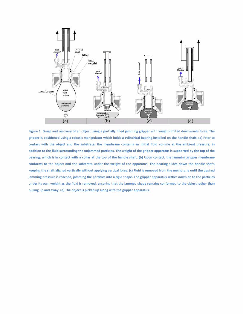
Figure 1: Grasp and recovery of an object using a partially filled jamming gripper with weight‐limited downwards force. The
gripper is positioned using a robotic manipulator which holds a cylindrical bearing installed on the handle shaft. (a) Prior to
contact with the object and the substrate, the membrane contains an initial fluid volume at the ambient pressure, in
addition to the fluid surrounding the unjammed particles. The weight of the gripper apparatus is supported by the top of the
bearing, which is in contact with a collar at the top of the handle shaft. (b) Upon contact, the jamming gripper membrane
conforms to the object and the substrate under the weight of the apparatus. The bearing slides down the handle shaft,
keeping the shaft aligned vertically without applying vertical force. (c) Fluid is removed from the membrane until the desired
jamming pressure is reached, jamming the particles into a rigid shape. The gripper apparatus settles down on to the particles
under its own weight as the fluid is removed, ensuring that the jammed shape remains conformed to the object rather than
pulling up and away. (d) The object is picked up along with the gripper apparatus.
Figure 2: The remotely operated vehicle (ROV) Hercules is a science work‐class ROV deployed from the dedicated 64m
support ship E/V Nautilus, operated by the Ocean Exploration Trust. The gripper, fluid drive, and pressure gauge were
installed in the port‐forward lower corner of the ROV (see detail in Figure 5.) The manipulator arm used to operate the
gripper is stowed at the starboard‐forward corner (to the left in the view shown.)
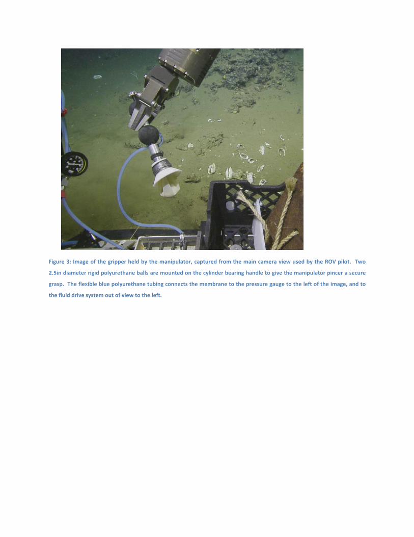
Figure 3: Image of the gripper held by the manipulator, captured from the main camera view used by the ROV pilot. Two
2.5in diameter rigid polyurethane balls are mounted on the cylinder bearing handle to give the manipulator pincer a secure
grasp. The flexible blue polyurethane tubing connects the membrane to the pressure gauge to the left of the image, and to
the fluid drive system out of view to the left.
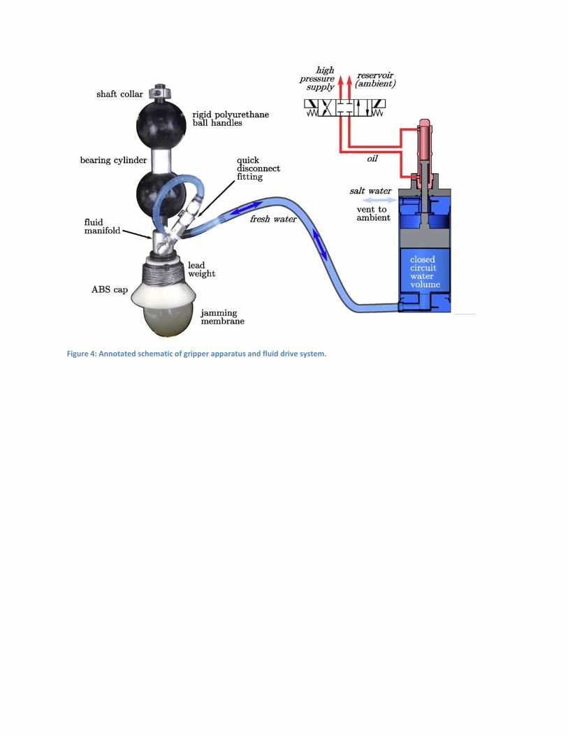
Figure 4: Annotated schematic of gripper apparatus and fluid drive system.
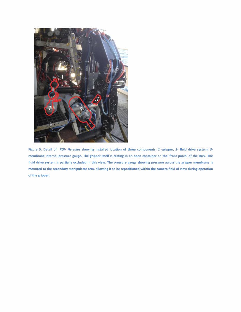
Figure 5: Detail of ROV Hercules showing installed location of three components: 1 ‐gripper, 2‐ fluid drive system, 3‐
membrane internal pressure gauge. The gripper itself is resting in an open container on the 'front porch' of the ROV. The
fluid drive system is partially occluded in this view. The pressure gauge showing pressure across the gripper membrane is
mounted to the secondary manipulator arm, allowing it to be repositioned within the camera field of view during operation
of the gripper.
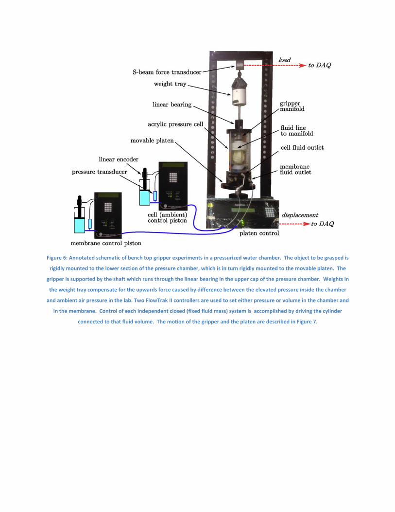
Figure 6: Annotated schematic of bench top gripper experiments in a pressurized water chamber. The object to be grasped is
rigidly mounted to the lower section of the pressure chamber, which is in turn rigidly mounted to the movable platen. The
gripper is supported by the shaft which runs through the linear bearing in the upper cap of the pressure chamber. Weights in
the weight tray compensate for the upwards force caused by difference between the elevated pressure inside the chamber
and ambient air pressure in the lab. Two FlowTrak II controllers are used to set either pressure or volume in the chamber and
in the membrane. Control of each independent closed (fixed fluid mass) system is accomplished by driving the cylinder
connected to that fluid volume. The motion of the gripper and the platen are described in Figure 7.
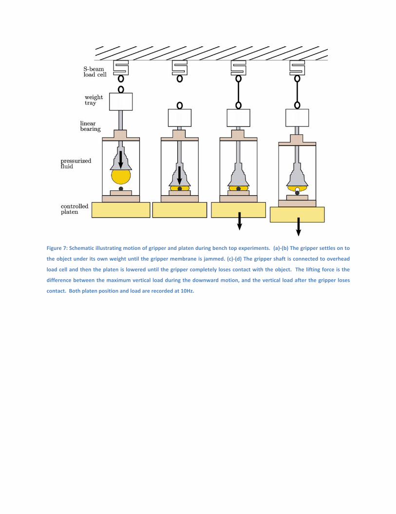
Figure 7: Schematic illustrating motion of gripper and platen during bench top experiments. (a)‐(b) The gripper settles on to
the object under its own weight until the gripper membrane is jammed. (c)‐(d) The gripper shaft is connected to overhead
load cell and then the platen is lowered until the gripper completely loses contact with the object. The lifting force is the
difference between the maximum vertical load during the downward motion, and the vertical load after the gripper loses
contact. Both platen position and load are recorded at 10Hz.
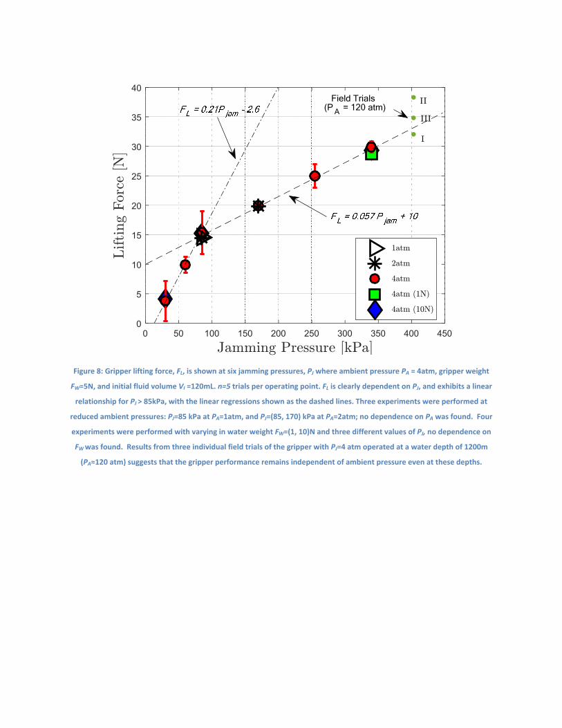
Figure 8: Gripper lifting force, FL, is shown at six jamming pressures, PJ where ambient pressure PA = 4atm, gripper weight
FW=5N, and initial fluid volume VI =120mL. n=5 trials per operating point. FL is clearly dependent on PJ, and exhibits a linear
relationship for PJ > 85kPa, with the linear regressions shown as the dashed lines. Three experiments were performed at
reduced ambient pressures: PJ=85 kPa at PA=1atm, and PJ=(85, 170) kPa at PA=2atm; no dependence on PA was found. Four
experiments were performed with varying in water weight FW=(1, 10)N and three different values of PJ, no dependence on
FW was found. Results from three individual field trials of the gripper with PJ=4 atm operated at a water depth of 1200m
(PA≈120 atm) suggests that the gripper performance remains independent of ambient pressure even at these depths.
0 50 100 150 200 250 300 350 400 4500
5
10
15
20
25
30
35
40Field Trials
(P A = 120 atm)
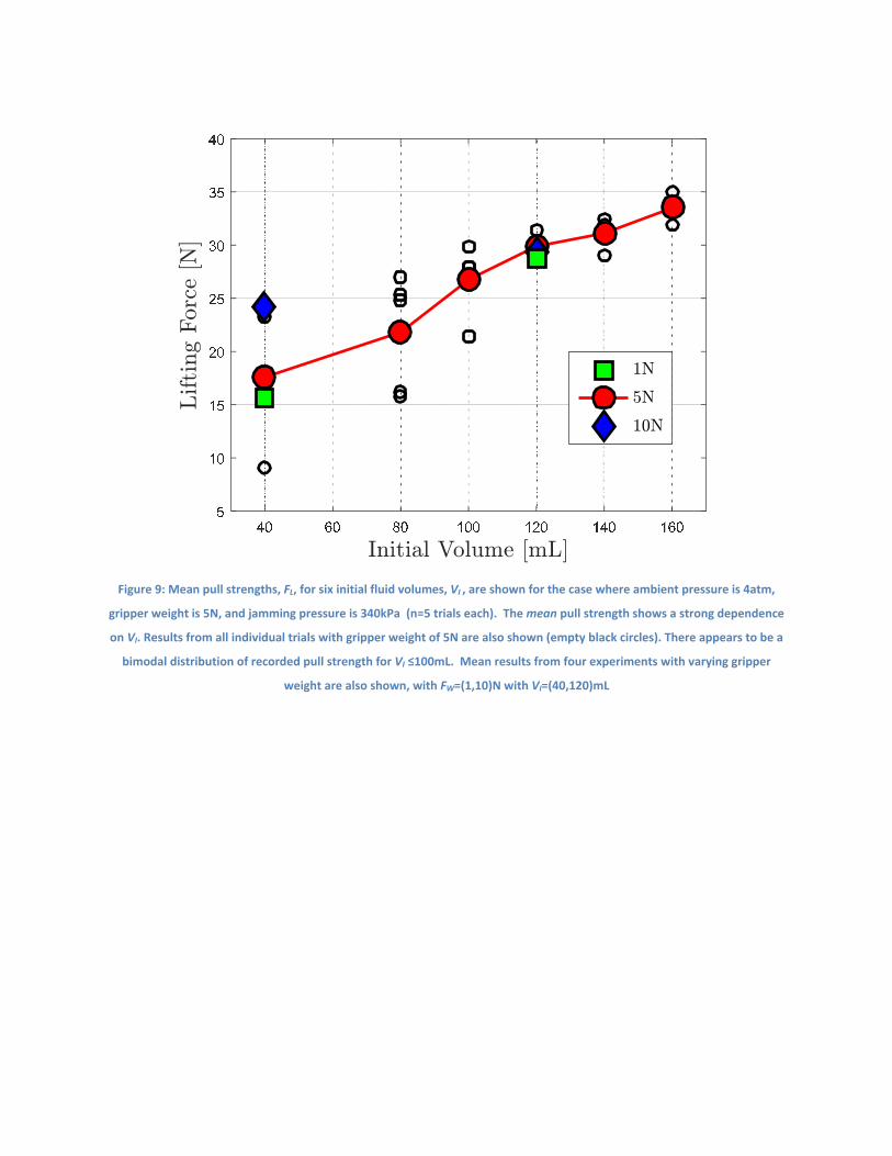
Figure 9: Mean pull strengths, FL, for six initial fluid volumes, VI , are shown for the case where ambient pressure is 4atm,
gripper weight is 5N, and jamming pressure is 340kPa (n=5 trials each). The mean pull strength shows a strong dependence
on VI. Results from all individual trials with gripper weight of 5N are also shown (empty black circles). There appears to be a
bimodal distribution of recorded pull strength for VI ≤100mL. Mean results from four experiments with varying gripper
weight are also shown, with FW=(1,10)N with VI=(40,120)mL
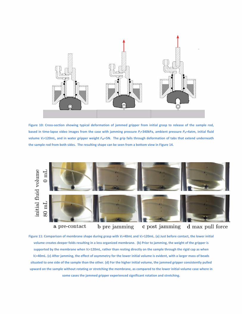
Figure 10: Cross‐section showing typical deformation of jammed gripper from initial grasp to release of the sample rod,
based in time‐lapse video images from the case with jamming pressure PJ=340kPa, ambient pressure PA=4atm, initial fluid
volume VI=120mL, and in water gripper weight FW=5N. The grip fails through deformation of tabs that extend underneath
the sample rod from both sides. The resulting shape can be seen from a bottom view in Figure 14.
Figure 11: Comparison of membrane shape during grasp with VI=40mL and VI=120mL. (a) Just before contact, the lower initial
volume creates deeper folds resulting in a less organized membrane. (b) Prior to jamming, the weight of the gripper is
supported by the membrane when VI=120mL, rather than resting directly on the sample through the rigid cap as when
VI=40mL. (c) After jamming, the effect of asymmetry for the lower initial volume is evident, with a larger mass of beads
situated to one side of the sample than the other. (d) For the higher initial volume, the jammed gripper consistently pulled
upward on the sample without rotating or stretching the membrane, as compared to the lower initial volume case where in
some cases the jammed gripper experienced significant rotation and stretching.
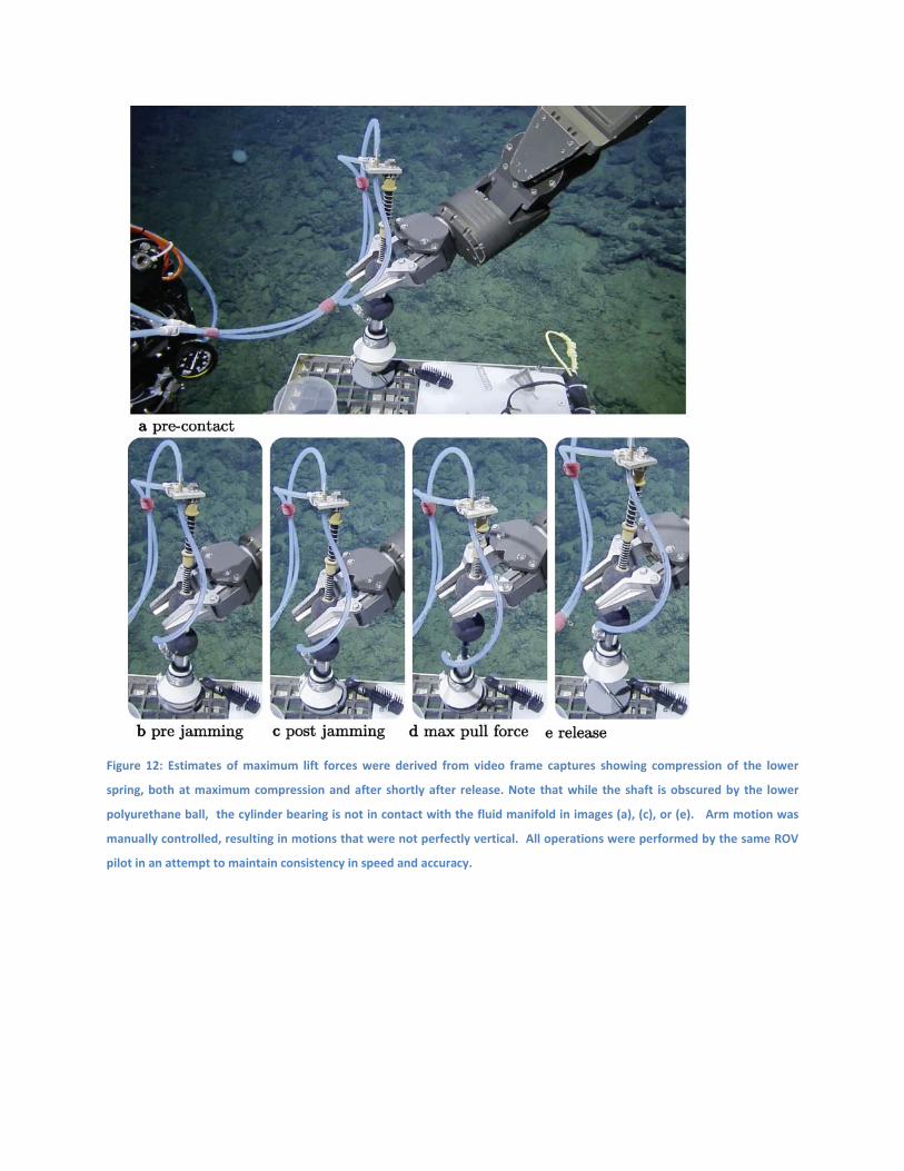
Figure 12: Estimates of maximum lift forces were derived from video frame captures showing compression of the lower
spring, both at maximum compression and after shortly after release. Note that while the shaft is obscured by the lower
polyurethane ball, the cylinder bearing is not in contact with the fluid manifold in images (a), (c), or (e). Arm motion was
manually controlled, resulting in motions that were not perfectly vertical. All operations were performed by the same ROV
pilot in an attempt to maintain consistency in speed and accuracy.
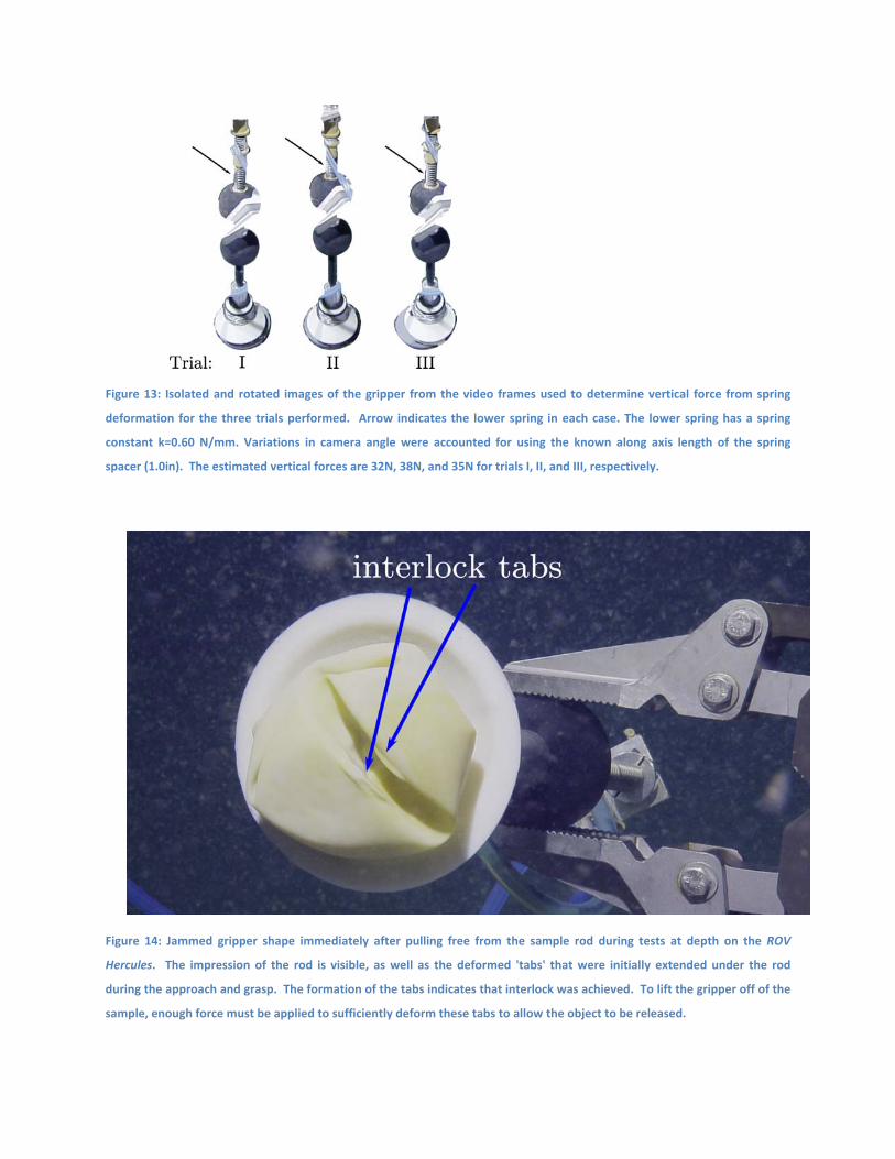
Figure 13: Isolated and rotated images of the gripper from the video frames used to determine vertical force from spring
deformation for the three trials performed. Arrow indicates the lower spring in each case. The lower spring has a spring
constant k=0.60 N/mm. Variations in camera angle were accounted for using the known along axis length of the spring
spacer (1.0in). The estimated vertical forces are 32N, 38N, and 35N for trials I, II, and III, respectively.
Figure 14: Jammed gripper shape immediately after pulling free from the sample rod during tests at depth on the ROV
Hercules. The impression of the rod is visible, as well as the deformed 'tabs' that were initially extended under the rod
during the approach and grasp. The formation of the tabs indicates that interlock was achieved. To lift the gripper off of the
sample, enough force must be applied to sufficiently deform these tabs to allow the object to be released.
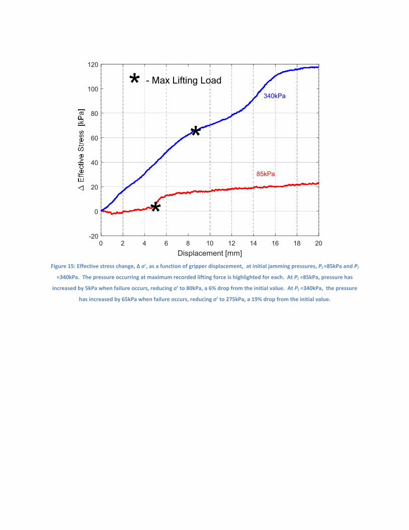
Figure 15: Effective stress change, ∆ σ', as a function of gripper displacement, at initial jamming pressures, PJ =85kPa and PJ
=340kPa. The pressure occurring at maximum recorded lifting force is highlighted for each. At PJ =85kPa, pressure has
increased by 5kPa when failure occurs, reducing σ' to 80kPa, a 6% drop from the initial value. At PJ =340kPa, the pressure
has increased by 65kPa when failure occurs, reducing σ' to 275kPa, a 19% drop from the initial value.
0 2 4 6 8 10 12 14 16 18 20
Displacement [mm]
-20
0
20
40
60
80
100
120
340kPa
85kPa
- Max Lifting Load