Pneumatic Parallel Grippers - Wainbee · G100 Series Pneumatic Grippers 2 G100 Series Pneumatic...
16
G100 Series Pneumatic Parallel Grippers
Transcript of Pneumatic Parallel Grippers - Wainbee · G100 Series Pneumatic Grippers 2 G100 Series Pneumatic...

G100 Series
Pneumatic Parallel Grippers

G100 Series Pneumatic Grippers
2 G100 Series Pneumatic Parallel Grippers
Robohand Gripping Solutions
Delivering better performance, lower maintenance, faster operation without added costs to
machine builders.
The Industry Standard for Machine Builders
• Low Maintenance: Shielded design ensures continuous operation in variety of manufacturing environments.
• Compact Design: High force, low profile, with a variety of stroke ranges.
• Easy Commissioning: Simple quick installation kits.
• Globally Supported: Global application support and service teams.
• Economical: Cost effective solutions with short delivery times.
G100 Series At-a-Glance
• 20 different models sized to match your application needs.
• Fast actuations from 60mS.
• Multiple stroke options from 5mm to 50mm.
• High grip force, small package from 56N to 558N (13 to 125 lbf).
• Shielded design for clean to moderate manufacturing environments.
• Interchangeable gripper fingers with competitive units using extended jaw option.
Dimensions and technical information subject to change without notice

2 Vertical Extended Jaws*
G100 Series Pneumatic Grippers
G xxM1x0
Product Type Description
G Gripper
Jaw Type Description
1 Horizontal Jaws
Size Description
08 Size 08
11 Size 11
18 Size 18
25 Size 25
Stroke Description
05, 10, 15, 20, 25 for Size 08
05, 10, 15, 20, 25 for Size 11
06, 12, 18, 24, 30 for Size 18
10, 20, 30, 40, 50 for Size 25
Seals Description
B Buna-N
Options Description
N No Options
The Industry Standard for Machine Builders 3
Accelerated Productivity: Twice the actuation speed of
competing units reducing manufacturing cycle times.
Performance: High grip force, low profile, with
strokes from 5mm to 50mm.
Low Maintenance: Shielded design ensures continuous
operation in variety of manufacturing environments.
Interchangeable Finger Design: Re-use gripper fingers used on
competing units with G100 series extended jaw option.
Smooth Operation: Rack and pinion design provides
consistent gripping actuation.
Space Saving: Compact design minimizes height profile
for constrained application space.
shown with extended jaw option
*Select models only, see finger
interchangeability table on page 15
Dimensions and technical information subject to change without notice

G110-08M Dimensions
[.04]1
[.787]20
[.27]
7
2X MAGNETORESISTIVE SENSOR SLOTS
CL CL
[.51]13[1.102]
28
[.15]3.82XM3 PORTS
OPEN
CLOSE
[.375]
9.5
[.7500]19.05
2XØ3H9 2.5 [0.10]
4XM3 4.5 [.17]
[
M3 7 [.28] TYP
Ø5H7 1.6 [.06] TYP
CL
CL
CL
CL
CL
Total Rated Grip Force ..................... 56 N 13 lbf
Pressure Range ............................... 3-7 Bar 40-100 psi
Cylinder Bore Diameter ................... 8 mm 0.31 in
Temperature Range, Buna Seals ..... -35ºC~80ºC -30ºF~180ºF
Accuracy .......................................... +/-.08 mm +/-.003 in
Repeatability .................................... +/-.08 mm +/-.003 in
Valve Required to Actuate ............... 4 way 2 position
Dimensions & Specs Common to All Strokes
[4.04]103
[.7874]20.00
[.138]3.5[.7874]
20.00
[3.45]88
[.6299]16.00
[.6299]16.00
[.138]3.5
[2.86]73
[.4331]11.00
[.138]3.5
[.5512]14.00
[2.27]
58[.138]
3.5[.2756]
7.00[.4331]
11.00
[1.68]43
[.4331]11.00
[.138]3.5
4 G100 Series Pneumatic Parallel Grippers
G110-08M-25 G110-08M-20
G110-08M-15G110-08M-10 G110-08M-05
I M 0 [ 0 [ 0 [
Third Angle Projection
Dimensions are symmetrical about
centerline
Imperial in. Metric [mm] 0.00 = ±.01 [0.] = [±.25] 0.000 = ±.005 [0.0] = [±.13] 0.0000 = ±.0005 [0.00] = [±.013]
All Dowel Holes are SF (Slip Fit). Locational Tolerance
±.0005" or [±.013mm]
UNLESS OTHERWISE NOTED ALL TOLERANCES ARE AS SHOWN BELOW
Metric ThreadsCourse Pitch
I M 0 [ 0 [ 0 [
Dimensions and technical information subject to change without notice

Stroke .............................................. 25 mm 0.98 in
Weight .............................................. 0.17 Kg 0.37 lbf
Displacement ................................... 1.2 cc 0.08 cu-in
Actuation ......................................... 0.10 sec 0.10 sec
Max Tensile Load on Jaws .............. 245 N 55 lbf
Max Compressive Load on Jaws .... 445 N 100 lbf
Max Moment on Jaws .................... 5.6 Nm 50 in-lbs
Stroke .............................................. 20 mm 0.79 in
Weight .............................................. 0.14 Kg 0.31 lbf
Displacement ................................... 1.0 cc 0.06 cu-in
Actuation ......................................... 0.09 sec 0.09 sec
Max Tensile Load on Jaws .............. 222 N 50 lbf
Max Compressive Load on Jaws .... 423 N 95 lbf
Max Moment on Jaws .................... 5.0 Nm 45 in-lbs
Stroke .............................................. 15 mm 0.59 in
Weight .............................................. 0.11 Kg 0.24 lbf
Displacement ................................... 0.7 cc 0.05 cu-in
Actuation ......................................... 0.08 sec 0.08 sec
Max Tensile Load on Jaws .............. 200 N 45 lbf
Max Compressive Load on Jaws .... 400 N 90 lbf
Max Moment on Jaws .................... 4.6 Nm 40 in-lbs
Stroke .............................................. 10 mm 0.39 in
Weight .............................................. 0.09 Kg 0.20 lbf
Displacement ................................... 0.5 cc 0.03 cu-in
Actuation ......................................... 0.07 sec 0.07 sec
Max Tensile Load on Jaws .............. 178 N 40 lbf
Max Compressive Load on Jaws .... 378 N 86 lbf
Max Moment on Jaws .................... 4 Nm 35 in-lbs
Stroke .............................................. 5 mm 0.20 in
Weight .............................................. 0.06 Kg 0.13 lbf
Displacement ................................... 0.3 cc 0.02 cu-in
Actuation ......................................... 0.06 sec 0.06 sec
Max Tensile Load on Jaws .............. 156 N 35 lbf
Max Compressive Load on Jaws .... 356 N 80 lbf
Max Moment on Jaws .................... 3.4 Nm 30 in-lbs
G110-08M Technical Data
Robohand G110-08M Specification 5
G110-08M-25-N-B
G110-08M-20-N-B
G110-08M-15-N-B
G110-08M-10-N-B
G110-08M-05-N-B
0
5
10
15
20
25
30
0 10 20 30 40 50 60 70 80
GRIP FORCE PER FINGER*
EFFECTIVE FINGER LENGTH - L (mm)
FIN
GER
FO
RCE
- F/
2 (
N)
FIN
GER
FO
RCE
- F/
2 (
N)
0
5
10
15
20
25
0 10 20 30 40 50 60
EFFECTIVE FINGER LENGTH - L (mm)
GRIP FORCE PER FINGER*
0
5
10
15
20
25
30
0 10 20 30 40 50 60 70
GRIP FORCE PER FINGER*
EFFECTIVE FINGER LENGTH - L (mm)
FIN
GER
FO
RCE
- F/
2 (
N)
0
5
10
15
20
25
30
0 10 20 30 40 50 60 70 80
GRIP FORCE PER FINGER*
EFFECTIVE FINGER LENGTH - L (mm)
FIN
GER
FO
RCE
- F/
2 (
N)
0
5
10
15
20
25
30
0 10 20 30 40 50 60 70 80
GRIP FORCE PER FINGER*
EFFECTIVE FINGER LENGTH - L (mm)
FIN
GER
FO
RCE
- F/
2 (
N)
7 bar (102 psi)6 bar (87 psi)5 bar (73 psi)4 bar (58 psi)3 bar (44 psi)MAX FINGER LENGTH
WARNINIG! DO NOT EXCEED MAXIMUM
EFFECTIVE FINGER LENGTH�
Dimensions and technical information subject to change without notice

[.06]1.5
[.945]24
[.35]9
2X MAGNETORESISTIVE SENSOR SLOTS
CL CL
I M 0 [ 0 [ 0 [
Third Angle Projection
Dimensions are symmetrical about
centerline
Imperial in. Metric [mm] 0.00 = ±.01 [0.] = [±.25] 0.000 = ±.005 [0.0] = [±.13] 0.0000 = ±.0005 [0.00] = [±.013]
All Dowel Holes are SF (Slip Fit). Locational Tolerance
±.0005" or [±.013mm]
UNLESS OTHERWISE NOTED ALL TOLERANCES ARE AS SHOWN BELOW
Metric ThreadsCourse Pitch
I M 0 [ 0 [ 0 [
G110-11M Dimensions
Total Rated Grip Force ..................... 104 N 23 lbf
Pressure Range ............................... 3-7 Bar 40-100 psi
Cylinder Bore Diameter ................... 11 mm 0.44 in
Temperature Range, Buna Seals ..... -35ºC~80ºC -30ºF~180ºF
Accuracy .......................................... +/-.08 mm +/-.003 in
Repeatability .................................... +/-.08 mm +/-.003 in
Valve Required to Actuate ............... 4 way 2 position
Dimensions & Specs Common to all Strokes
[2.29]58
[.4331]11.00
[.138]3.5
[.2756]7.00
[.26]7
[.67]17
[1.437]36.5
2XM3 PORTSOPEN
CLOSE
[.375]9.5
[.7500]19.05 4XM3 5 [.19]
2XØ3H9 2.5 [0.10]
M3 8 [.32] TYP
Ø5H7 1.6 [.06] TYP
CL
CL
CL
CL
CL
[3.35]
85
[.6299]16.00
[.138]3.5[.6299]
16.00
[2.88]73
[.4331]11.00
[.138]3.5 [.5512]
14.00
[4.06]103
[.7874]20.00
[.138]3.5[.7874]
20.00
[1.70]43
[.4331]11.00
[.138]3.5
6 G100 Series Pneumatic Parallel Grippers
G110-11M-25 G110-11M-20
G110-11M-15G110-11M-10 G110-11M-05
Dimensions and technical information subject to change without notice

Stroke .............................................. 25 mm 0.98 in
Weight .............................................. 0.25 Kg 0.55 lbf
Displacement ................................... 1.2 cc 0.15 cu-in
Actuation ......................................... 0.12 sec 0.12 sec
Max Tensile Load on Jaws .............. 490 N 110 lbf
Max Compressive Load on Jaws .... 890 N 200 lbf
Max Moment on Jaws .................... 11 Nm 100 in-lbs
Stroke .............................................. 20 mm 0.79 in
Weight .............................................. 0.21 Kg 0.46 lbf
Displacement ................................... 1.9 cc 0.12 cu-in
Actuation ......................................... 0.11 sec 0.11 sec
Max Tensile Load on Jaws .............. 445 N 100 lbf
Max Compressive Load on Jaws .... 845 N 190 lbf
Max Moment on Jaws .................... 10 Nm 90 in-lbs
Stroke .............................................. 15 mm 0.59 in
Weight .............................................. 0.17 Kg 0.37 lbf
Displacement ................................... 1.5 cc 0.09 cu-in
Actuation ......................................... 0.10 sec 0.10 sec
Max Tensile Load on Jaws .............. 400 N 90 lbf
Max Compressive Load on Jaws .... 800 N 180 lbf
Max Moment on Jaws .................... 9 Nm 80 in-lbs
Stroke .............................................. 10 mm 0.39 in
Weight .............................................. 0.13 Kg 0.29 lbf
Displacement ................................... 1.0 cc 0.06 cu-in
Actuation ......................................... 0.09 sec 0.09 sec
Max Tensile Load on Jaws .............. 350 N 80 lbf
Max Compressive Load on Jaws .... 750 N 170 lbf
Max Moment on Jaws .................... 8 Nm 70 in-lbs
Stroke .............................................. 5 mm 0.20 in
Weight .............................................. 0.09 Kg 0.20 lbf
Displacement ................................... 0.5 cc 0.03 cu-in
Actuation ......................................... 0.08 sec 0.08 sec
Max Tensile Load on Jaws .............. 311 N 70 lbf
Max Compressive Load on Jaws .... 712 N 160 lbf
Max Moment on Jaws .................... 7 Nm 60 in-lbs
G110-11M Technical Data
7Robohand G110-11M Specification
G110-11M-25-N-B
G110-11M-20-N-B
G110-11M-15-N-B
G110-11M-10-N-B
G110-11M-05-N-B
0 10 20 30 40 50 60 70
5101520253035404550
GRIP FORCE PER FINGER*
EFFECTIVE FINGER LENGTH - L (mm)
FIN
GER
FO
RCE
- F/
2 (
N)
0
0
10
20
30
40
50
60
0 10 20 30 40 50 60 70 80
GRIP FORCE PER FINGER*
EFFECTIVE FINGER LENGTH - L (mm)
FIN
GER
FO
RCE
- F/
2 (
N)
0
10
20
30
40
50
60
0 10 20 30 40 50 60 70 80
GRIP FORCE PER FINGER*
EFFECTIVE FINGER LENGTH - L (mm)
FIN
GER
FO
RCE
- F/
2 (
N)
5101520253035404550
0 10 20 30 40 50 60 70 80
GRIP FORCE PER FINGER*
EFFECTIVE FINGER LENGTH - L (mm)
FIN
GER
FO
RCE
- F/
2 (
N)
0
051015202530354045
0 10 20 30 40 50 60
GRIP FORCE PER FINGER*
EFFECTIVE FINGER LENGTH - L (mm)
FIN
GER
FO
RCE
- F/
2 (
N)
7 bar (102 psi)6 bar (87 psi)5 bar (73 psi)4 bar (58 psi)3 bar (44 psi)MAX FINGER LENGTH
WARNINIG! DO NOT EXCEED MAXIMUM
EFFECTIVE FINGER LENGTH�
Dimensions and technical information subject to change without notice

[1.693]43
[.28]7
[.87]22
2XM5 PORTS OPENCLOSE
[1.5000]38.10
[.750]19.1
4XM5 5 [.19]
2XØ5H9 2.5 [0.10]
M4 10 [.40] TYP
Ø6H7 1.6 [.06] TYP
0.
0.?? se
CL
CL
CL
CL
CL
0.
0.?? se
0.
0.?? se
0.
0.?? se
0.
0.?? se
G110-18M Dimensions
Total Rated Grip Force ..................... 260 N 58 lbf
Pressure Range ............................... 3-7 Bar 40-100 psi
Cylinder Bore Diameter ................... 17.5 mm 0.69 in
Temperature Range, Buna Seals ..... -35ºC~80ºC -30ºF~180ºF
Accuracy .......................................... +/-.08 mm +/-.003 in
Repeatability .................................... +/-.08 mm +/-.003 in
Valve Required to Actuate ............... 4 way 2 position
Dimensions & Specs Common to all Strokes
[.06]1.5
[1.181]30
[.39]10
2X MAGNETORESISTIVE SENSOR SLOTS
CL CL
[4.92]125
[.9055]23.00
[.9055]23.00
[.177]4.5
30
24
18
12
6
[2.79]71
[.3150]8.00
[.5512]14.00
[.177]4.5
0.
0.?? se
0.
0.?? se
0.
0.?? se
0.
0.?? se
0.
0.?? se
[.5906]15.00
[.6693]17.00
[3.50]89
[.177]4.50
0.
0.?? se
0.
0.?? se
0.
0.?? se
0.
0.?? se
0.
0.?? se
[2.12]54
[.5512]14.00
[.157]4.0
30
24
18
12
6
[4.21]107
74]00
[.7874]20.00
[
[.177]4.5
30
24
18
12
6
8 G100 Series Pneumatic Parallel Grippers
G110-18M-30 G110-18M-24
G110-18M-18G110-18M-12 G110-18M-06
I M 0 [ 0 [ 0 [
Third Angle Projection
Dimensions are symmetrical about
centerline
Imperial in. Metric [mm] 0.00 = ±.01 [0.] = [±.25] 0.000 = ±.005 [0.0] = [±.13] 0.0000 = ±.0005 [0.00] = [±.013]
All Dowel Holes are SF (Slip Fit). Locational Tolerance
±.0005" or [±.013mm]
UNLESS OTHERWISE NOTED ALL TOLERANCES ARE AS SHOWN BELOW
Metric ThreadsCourse Pitch
I M 0 [ 0 [ 0 [
Dimensions and technical information subject to change without notice

Stroke .............................................. 30 mm 1.18 in
Weight .............................................. 0.41 Kg 0.90 lbf
Displacement ................................... 7.2 cc 0.44 cu-in
Actuation ......................................... 0.25 sec 0.25 sec
Max Tensile Load on Jaws .............. 1223 N 275 lbf
Max Compressive Load on Jaws .... 2225 N 500 lbf
Max Moment on Jaws .................... 28 Nm 250 in-lbs
Stroke .............................................. 24 mm 0.94 in
Weight .............................................. 0.34 Kg 0.75 lbf
Displacement ................................... 5.8 cc 0.35 cu-in
Actuation ......................................... 0.21 sec 0.21 sec
Max Tensile Load on Jaws .............. 1112 N 250 lbf
Max Compressive Load on Jaws .... 2113 N 475 lbf
Max Moment on Jaws .................... 25 Nm 225 in-lbs
Stroke .............................................. 18 mm 0.71 in
Weight .............................................. 0.28 Kg 0.62 lbf
Displacement ................................... 4.3 cc 0.26 cu-in
Actuation ......................................... 0.17 sec 0.17 sec
Max Tensile Load on Jaws .............. 1000 N 225 lbf
Max Compressive Load on Jaws .... 2000 N 450 lbf
Max Moment on Jaws .................... 23 Nm 200 in-lbs
Stroke .............................................. 12 mm 0.47 in
Weight .............................................. 0.22 Kg 0.48 lbf
Displacement ................................... 2.9 cc 0.18 cu-in
Actuation ......................................... 0.13 sec 0.13 sec
Max Tensile Load on Jaws .............. 890 N 200 lbf
Max Compressive Load on Jaws .... 1890 N 425 lbf
Max Moment on Jaws .................... 20 Nm 175 in-lbs
Stroke .............................................. 6 mm 0.24 in
Weight .............................................. 0.20 Kg 0.44 lbf
Displacement ................................... 1.5 cc 0.09 cu-in
Actuation ......................................... 0.09 sec 0.09 sec
Max Tensile Load on Jaws .............. 778 N 175 lbf
Max Compressive Load on Jaws .... 1779 N 400 lbf
Max Moment on Jaws .................... 17 Nm 150 in-lbs
G110-18M Technical Data
9Robohand G110-18M Specification
G110-18M-30-N-B
G110-18M-24-N-B
G110-18M-18-N-B
G110-18M-12-N-B
G110-18M-06-N-B
020
40
60
80
100
120140
0 20 40 60 80 100 120
GRIP FORCE PER FINGER*
EFFECTIVE FINGER LENGTH - L (mm)
FIN
GER
FO
RCE
- F/
2 (
N)
020
40
60
80
100
120140
0 20 40 60 80 100 120
GRIP FORCE PER FINGER*
EFFECTIVE FINGER LENGTH - L (mm)
FIN
GER
FO
RCE
- F/
2 (
N)
020
40
60
80
100
120140
0 20 40 60 80 100 120
GRIP FORCE PER FINGER*
EFFECTIVE FINGER LENGTH - L (mm)
FIN
GER
FO
RCE
- F/
2 (
N)
0 10 20 30 40 50 60 70 80 90 100
0
020
40
60
80
100
120140
GRIP FORCE PER FINGER*
EFFECTIVE FINGER LENGTH - L (mm)
FIN
GER
FO
RCE
- F/
2 (
N)
0 10 20 30 40 50 60 70 80
020
40
60
80
100
120140
GRIP FORCE PER FINGER*
EFFECTIVE FINGER LENGTH - L (mm)
FIN
GER
FO
RCE
- F/
2 (
N)
7 bar (102 psi)6 bar (87 psi)5 bar (73 psi)4 bar (58 psi)3 bar (44 psi)MAX FINGER LENGTH
WARNINIG! DO NOT EXCEED MAXIMUM
EFFECTIVE FINGER LENGTH�
Dimensions and technical information subject to change without notice
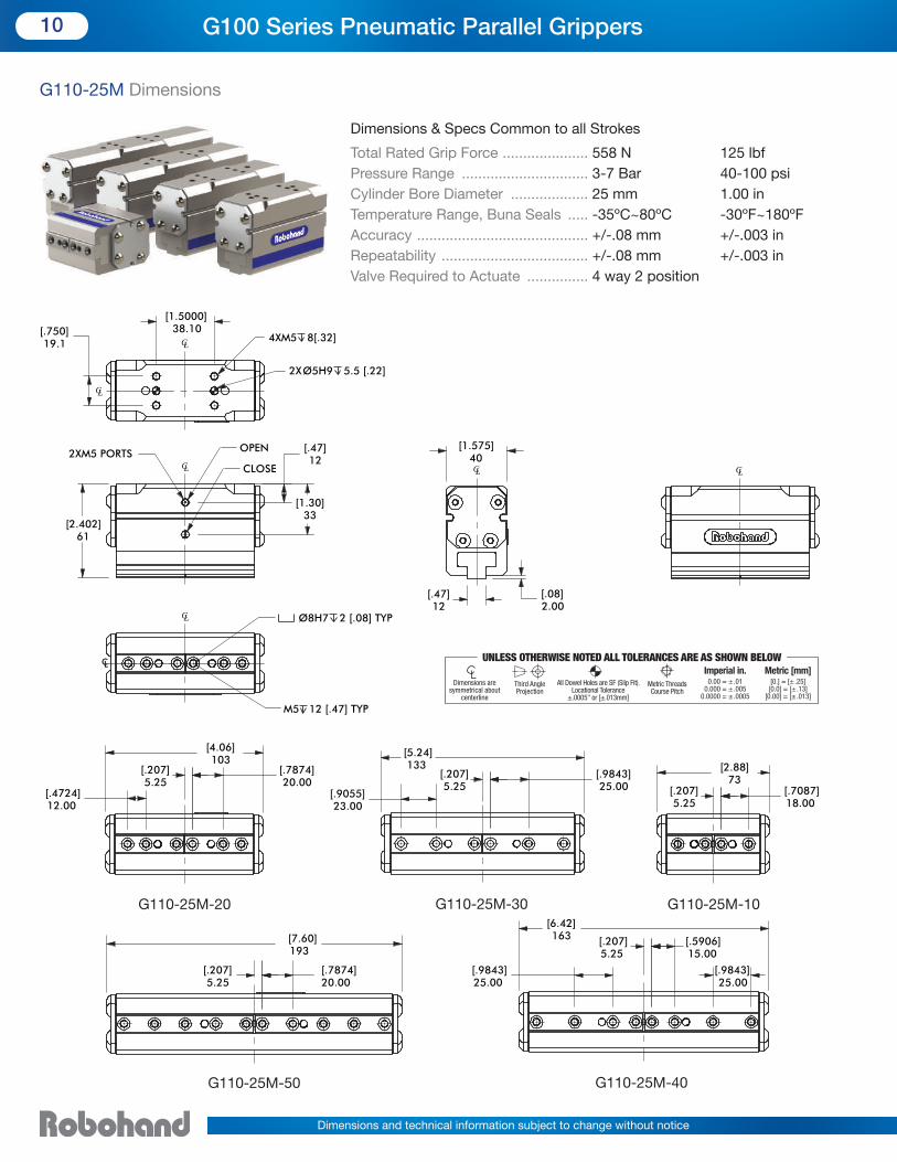
G110-25M Dimensions
Dimensions & Specs Common to all Strokes
[2.402]61
[.47]12
[1.30]33
2XM5 PORTS OPEN
CLOSE
[1.5000]38.10[.750]
19.1 4XM5 8[.32]
2XØ5H9 5.5 [.22]
Ø8H7 2 [.08] TYP
M5 12 [.47] TYP
CL
CL
CL
CL
CL
[1.575]40
[.08]2.00
[.47]12
CL CL
[.207]5.25
[.4724]12.00
[4.06]103
[.7874]20.00
[.207]5.25
[2.88]73
[.7087]18.00
Ø
0.
0.?? se
on Jaws
0.
0.?? se
on Jaws
0.
0.?? se
on Jaws
0.?? se
on Jaws
1.
0.?? se
on Jaws
[.9055]23.00
[.207]5.25
[5.24]133
[.9843]25.00
[
30 0.
0.?? se
40 0.
0.?? se
20 0.
0.?? se
10
0.?? se
50 1.
0.?? se
[.207]5.25
[7.60]193
[.7874]20.00
[6.42]163 [.207]
5.25[.5906]15.00
[.9843]25.00
[.9843]25.00
[
30
0.?? se
40
0.?? se
20
0.?? se
10
0.?? se
50
0.?? se
10 G100 Series Pneumatic Parallel Grippers
G110-25M-50 G110-25M-40
G110-25M-30G110-25M-20 G110-25M-10
Total Rated Grip Force ..................... 558 N 125 lbf
Pressure Range ............................... 3-7 Bar 40-100 psi
Cylinder Bore Diameter ................... 25 mm 1.00 in
Temperature Range, Buna Seals ..... -35ºC~80ºC -30ºF~180ºF
Accuracy .......................................... +/-.08 mm +/-.003 in
Repeatability .................................... +/-.08 mm +/-.003 in
Valve Required to Actuate ............... 4 way 2 position
I M 0 [ 0 [ 0 [
Third Angle Projection
Dimensions are symmetrical about
centerline
Imperial in. Metric [mm] 0.00 = ±.01 [0.] = [±.25] 0.000 = ±.005 [0.0] = [±.13] 0.0000 = ±.0005 [0.00] = [±.013]
All Dowel Holes are SF (Slip Fit). Locational Tolerance
±.0005" or [±.013mm]
UNLESS OTHERWISE NOTED ALL TOLERANCES ARE AS SHOWN BELOW
Metric ThreadsCourse Pitch
I M 0 [ 0 [ 0 [
Dimensions and technical information subject to change without notice

Stroke .............................................. 50 mm 1.97 in
Weight .............................................. 1.22 Kg 2.68 lbf
Displacement ................................... 25.31 cc 1.55 cu-in
Actuation ......................................... 0.61 sec 0.61 sec
Max Tensile Load on Jaws .............. 2450 N 550 lbf
Max Compressive Load on Jaws .... 4450 N 1000 lbf
Max Moment on Jaws .................... 55 Nm 500 in-lbs
Stroke .............................................. 40 mm 1.57 in
Weight .............................................. 1.03 Kg 2.27 lbf
Displacement ................................... 20.3 cc 1.24 cu-in
Actuation ......................................... 0.52 sec 0.52 sec
Max Tensile Load on Jaws .............. 2225 N 500 lbf
Max Compressive Load on Jaws .... 4225 N 950 lbf
Max Moment on Jaws .................... 50 Nm 450 in-lbs
Stroke .............................................. 30 mm 1.18 in
Weight .............................................. 0.85 Kg 1.87 lbf
Displacement ................................... 15.19 cc 0.93 cu-in
Actuation ......................................... 0.44 sec 0.44 sec
Max Tensile Load on Jaws .............. 2000 N 450 lbf
Max Compressive Load on Jaws .... 4000 N 900 lbf
Max Moment on Jaws .................... 45 Nm 400 in-lbs
Stroke .............................................. 20 mm 0.79 in
Weight .............................................. 0.64 Kg 1.41 lbf
Displacement ................................... 10.12 cc 0.62 cu-in
Actuation ......................................... 0.36 sec 0.36 sec
Max Tensile Load on Jaws .............. 1750 N 400 lbf
Max Compressive Load on Jaws .... 3775 N 850 lbf
Max Moment on Jaws .................... 40 Nm 350 in-lbs
Stroke .............................................. 10 mm 0.39 in
Weight .............................................. 0.42 Kg 0.92 lbf
Displacement ................................... 5.06 cc 0.31 cu-in
Actuation ......................................... 0.28 sec 0.28 sec
Max Tensile Load on Jaws .............. 1550 N 350 lbf
Max Compressive Load on Jaws .... 3550 N 800 lbf
Max Moment on Jaws .................... 35 Nm 300 in-lbs
G110-25M Technical Data
11Robohand G110-25M Specification
G110-25M-50-N-B
G110-25M-40-N-B
G110-25M-30-N-B
G110-25M-20-N-B
G110-25M-10-N-B
0
50
100
150
200
250
300
0 20 40 60 80 100 120 140 160
GRIP FORCE PER FINGER*
EFFECTIVE FINGER LENGTH - L (mm)
FIN
GER
FO
RCE
- F/
2 (
N)
0
50
100
150
200
250
300
0 20 40 60 80 100 120 140 160
GRIP FORCE PER FINGER*
EFFECTIVE FINGER LENGTH - L (mm)
FIN
GER
FO
RCE
- F/
2 (
N)
0
50
100
150
200
250
300
0 20 40 60 80 100 120 140 160
GRIP FORCE PER FINGER*
EFFECTIVE FINGER LENGTH - L (mm)
FIN
GER
FO
RCE
- F/
2 (
N)
0
50
100
150
200
250
0 20 40 60 80 100 120 140 160
GRIP FORCE PER FINGER*
EFFECTIVE FINGER LENGTH - L (mm)
FIN
GER
FO
RCE
- F/
2 (
N)
0
50
100
150
200
250
0 20 40 60 80 100 120 140 160
GRIP FORCE PER FINGER*
EFFECTIVE FINGER LENGTH - L (mm)
FIN
GER
FO
RCE
- F/
2 (
N)
7 bar (102 psi)6 bar (87 psi)5 bar (73 psi)4 bar (58 psi)3 bar (44 psi)MAX FINGER LENGTH
WARNINIG! DO NOT EXCEED MAXIMUM
EFFECTIVE FINGER LENGTH�
Dimensions and technical information subject to change without notice

G100 Series Accessories
Part Number Description Qty Required
PLFT-021 Pneumatic air fitting, straight M3 screw to 3mm tube push-in 2
20961-11 Jaw locating sleeve for precise finger mounting 4
SLKT-244 Includes:
End gasket G110-08M (Qty 2)
Seal: U-cup buna replacement seal (Qty 4)
Button head socket cap screws (Qty 8)
1
Part Number Description Qty Required
PLFT-021 Pneumatic air fitting, straight M3 screw to 3mm tube push-in 2
20961-11 Jaw locating sleeve for precise finger mounting 4
SLKT-245 Includes:
End gasket G110-11M (Qty 2)
Seal: U-cup buna replacement seal (Qty 4)
Button head socket cap screws (Qty 8)
1
G110-08M, G120-08M Accessories
G110-11M , G120-11M Accessories
12 G100 Series Grippers Accessories
Part Number Description Qty Required
OHSN-021 Sensor, NPN magneto resistive type, 4mm Barrel 1, 2, 3 or 4
OHSP-021 Sensor, PNP magneto resistive type, 4mm Barrel 1, 2, 3 or 4
CABL-010 Cable straight, quick disconnect, socket, 3 conductor, 2M length 1, 2, 3 or 4
G100 Series Common Accessories
Long Barrel 4mm Straight Sensor
Cable Straight, Quick Disconnect,
Socket, 3 Conductor, 2M Length
OHSP-021
OHSN-021
LOAD
LOAD
PNPSENSOR
NPNSENSOR
PIN 1: BROWN ( + )
PIN 4: BLACK (SIGNAL)
PIN 3: BLUE ( - )1
4
3
PIN 1: BROWN ( + )PIN 4: BLACK (SIGNAL)PIN 3: BLUE ( - )
PIN 1: BROWN ( + )PIN 4: BLACK (SIGNAL)PIN 3: BLUE ( - )
4.5 - 28 VDC100 mA MAXGND ( - )
4.5 - 28 VDC100 mA MAXGND ( - )
Dimensions and technical information subject to change without notice

G100 Series Accessories
13G100 Series Grippers Accessories
Part Number Description Qty Required
PLFT-041 Pneumatic air fitting, right angle, M5 screw to 6mm tube push-in 2
OFSV-004 Valve kit, failsafe, M5 ports 1
20962-11 Jaw locating sleeve for precise finger mounting 4
SLKT-246 Includes:
End gasket G110-18M (Qty 2)
Seal: U-cup buna replacement seal (Qty 4)
Button head socket cap screws (Qty 8)
1
G110-18M, G120-18M Accessories
Part Number Description Qty Required
PLFT-041 Pneumatic air fitting, right angle, M5 screw to 6mm tube push-in 2
OFSV-004 Valve kit, failsafe, M5 ports 1
20963-11 Jaw locating sleeve for precise finger mounting 4
SLKT-247 Includes:
End gasket G110-25M (Qty 2)
Seal: U-cup bunareplacement seal (Qty 4)
Button head socket cap screws (Qty 8)
1
G110-25M, G120-25M Accessories
Jaw Locating Sleeve for Precise Finger Mounting
U-cup Buna Replacement Seal Button Head Socket Cap ScrewsValve Kit, Failsafe, M5 Ports
End GasketPneumatic Air Fittings
Dimensions and technical information subject to change without notice

G100 Series Quick Installation Kits
14 G100 Series Quick Installation Kits
Part Number Includes Quantity Description
G110-QKST-101 OHSP-021 2 Sensor, PNP magneto resistive type, 4mm barrel
PLFT-021 2 Pneumatic air fitting, M3 screw to 3mm tube push-in
20961-11 4 Jaw locating sleeve for precise finger mounting
SHSM02.5C10 4 Finger mounting screws
G110-08M, G120-08M Quick Installation Kits
zPart Number Includes Quantity Description
G110-QKST-102 OHSP-021 2 Sensor, PNP magneto Resistive type, 4mm barrel
PLFT-021 2 Pneumatic air fitting, M3 screw to 3mm tube push-in
20961-11 4 Jaw locating sleeve for precise finger mounting
SHSM03C10 4 Finger mounting screws
G110-11M, G120-11M Quick Installation Kits
Part Number Includes Quantity Description
G110-QKST-103 OHSP-021 2 Sensor, PNP magneto resistive type, 4mm Barrel
PLFT-041 2 Pneumatic air fitting, right angle, M5 screw to 6mm tube push-in
20962-11 4 Jaw locating sleeve for precise finger mounting
SHSM04C12 4 Finger mounting screws
G110-18M, G120-18M Quick Installation Kits
Part Number Includes Quantity Description
G110-QKST-104 OHSP-021 2 Sensor, PNP magneto resistive type, 4mm barrel
PLFT-041 2 Pneumatic air fitting, right angle, M5 screw to 6mm tube push-in
20963-11 4 Jaw locating sleeve for precise finger mounting
SHSM05C16 4 Finger mounting screws
G110-25M, G120-25M Quick Installation Kits
2 Sensors 2 Air Fittings 4 Jaw Locating Finger Sleeves 4 Finger Mounting Screws
Commissioning Kits for Easy Ordering
• Includes just what you need for easy installation.
• One quick installation kit required per gripper.
• Fast, simple convenient ordering.
Dimensions and technical information subject to change without notice

Extended Jaw OptionPart Number
Mounts to G110Series Part Number
Finger Compatiblewith SMC Part Number
Application Notes(Ref: 6 Bar, 20mm finger length, ext. grip)
G110-FNGR-08M-05 G110-08M-05-N-B MHZ2-10 G110 has 1mm extra stroke, 9N extra total force
G110-FNGR-08M-10 G110-08M-10-N-B MHZL2-10 G110 has 2mm extra stroke, 10N extra total force
G110-FNGR-11M-05 G110-11M-05-N-B MHZ2-16 G110 has 1mm less stroke, 13N less total force
G110-FNGR-11M-10 G110-11M-10-N-B MHZL2-16 G110 has 2mm less stroke, 11N less total force
G110-FNGR-18M-12 G110-18M-12-N-B MHZ2-25 G110 has 2mm less stroke, 24N extra total force
G110-FNGR-18M-24 G110-18M-24-N-B MHZL2-25 G110 has 2mm extra stroke, 46N extra total force
G110-FNGR-25M-20 G110-25M-20-N-B MHZ2-32 G110 has 2mm less stroke, 20N less total force
G100 Series Extended Jaw Option
15G100 Series Grippers Finger Interchangeability
G110 Extended Jaw Option, Finger Interchangeability Table* (G120 units ship with extended jaw option installed)
G100 Series Interchangeable Fingers with Extended Gripper Jaw Option.
Fast Gripper Commissioning
• Re-use your existing gripper fingers.
• Same finger mounting hole pattern as competitive units.
• G100 Series Grippers Deliver:
*Verify acceptable stroke and force changes in the table above for your application.
G120 units are shipped with the extended jaw option mounted from factory.
SMC is a registered trademark of SMC Corporation.
- Low Maintenance Shielded Design
- Smooth Rack and Pinion Operation
- Fast cycle times down to 0.06 seconds
- Low height profile
- All-in-one Commissioning Kits
100% Finger Compatible
competitive model
Dimensions and technical information subject to change without notice

www.destaco.com CLAMPING TECHNOLOGYDimensions and technical information are subject to change without notice
Workholding
• Widest variety of workholding products• High durability and reliability• Flexible solutions for all applications• Custom products for unique requirements
Automation
• Broad range of engineered automation products • Complementary products for modular integration • Unmatched accuracy, reliability and performance • Unparalleled global sales, service and engineering support
© Copyright, 2014 DE-STA-CO. All rights for layout, photos and text rest with the publisher DE-STA-CO. All photomechanical or other reproductions only with our express permission. All sales are based on our terms and conditions of sale, delivery and payment. RBH-GSG-C-0414-US
1025 Doris RoadAuburn Hills, MI 48326 USATel 1.888.DESTACOFax 1.248.836.6901Email [email protected]
NORTH AMERICADE-STA-CO HeadquartersAuburn Hills, MichiganTel: 1.248.836.6700Toll Free: 1.888.DESTACOMarketing: [email protected] Service: [email protected]
Charlevoix, MichiganTel: 1.888.DESTACOCustomer Service: [email protected]
Wheeling, IllinoisTel: 1.800.645.5207Customer Service: [email protected]
Red Wing, Minnesota (Central Research Laboratories)Tel: 651.385.2142Customer Service: [email protected]
SOUTH AMERICABrazilTel: 0800-124070Customer Service: [email protected]
ASIAThailandTel: +66-2-326-0812Customer Service: [email protected]
ChinaTel: +86-21-2411-2600Customer Service: [email protected]
IndiaTel: +91-80-41123421-426Customer Service: [email protected]
EUROPEGermanyTel: +49-6171-705-0Customer Service: [email protected]
FranceTel: +33-1-3996-5000Customer Service: [email protected]
UKTel: +44-1902-797980Customer Service: [email protected]
SpainTel: +34-936361680Customer Service: [email protected]
NetherlandsTel: +31-297285332Customer Service: [email protected]
GLOBAL LOCATIONS