Ultimately, all lifting insert tension bars may not be equal

Chapter 11
STRESS AND DEFORMATIONANALYSIS OF LINEARELASTIC BARS IN TENSION
Figure 11.1:
In Chapter10, the equilibrium, kinematic and constitutive equations for a general three-dimensionalsolid deformable body were summarized. Special cases were also presented for the 2-D and 1-D stateof stress. In this chapter we will discuss the application of these 1-D results to the stress and defor-mation analysis of linear elastic bars in tension.
11.1 Necessary Equations for a 1-D Elastic Solid
For a linear elastic solid under static equilibrium, we can now summarize the following three sets ofequations for any body which has a uniaxial state of stress:
1. Static Equilibrium Equation (Conservation of Linear Momentum)
237

238CHAPTER 11. STRESS AND DEFORMATION ANALYSIS OF LINEAR ELASTIC BARS IN TENSION
x-component:dσxx
dx+ ρgx = 0 (11.1)
2. Constitutive Equation for Linear Elastic Isotropic Material
σxx = Eεxx (11.2)
3. Kinematics (strain-displacement equation) for small strain
εxx =∂ux
∂x(11.3)
Note that by 1-D we mean that we have a one-dimensional state of stress, i.e., stress is a functionof only one position variable (say x). However, the body is still three-dimensional but for reasonsto be discussed, will generally be restricted in some way with regard to the member geometry (likeslender beams, rods, bars, tubes, etc.), cross-sectional area, length, type of loads allowed, etc. Mostproblems will involve a long, slender geometry. In this and following chapters, we will consider indetail three special cases:
• Bar with axial force only
1 2A rigid horizo nta l bar isattached to the botto mof each vertica l bar. Thehorizonta l bar rema inshorizonta l when p ulleddow nward
A1 , E1 , L1 A2 , E2 , L2
P
Figure 11.2:
• Bar (or pipe) in torsion
• Beam in bending
In each case, we will develop expressions for the appropriate displacement (or twist) and stresswithin the body as function of position within the body.
11.2 General Solution Procedure
The governing equations for an elastic solid body with a 1-D stress state (function of x) are given byequations (11.1)-(11.3). The three equations for a set of coupled ordinary differential equations thatmust, in general, be solved simultaneously for the stress σxx, strain εxx and displacement ux. As inthe solution of any differential equation, boundary conditions must be specified to solve this boundary

11.3. EXAMPLES OF THE 1-D AXIAL BAR PROBLEMS 239
20′′
4′′
25, 000 in-lbs
G = 5.5 × 10⁶ psi
Figure 11.3:
P
La
x
Figure 11.4:
value problem. These boundary condition must be either displacements or stresses (tractions) onevery point of the boundary. Consequently, for every problem, we must satisfy the following four(4) sets of equations:
Four Sets of Equations to be Satisfied for A Solid Deformable Body with 1-D Stress StateStatic Equilibrium Equation (from COLM): dσxx
dx + ρgx = 0Constitutive Equation (Stress-Strain): σxx = Eεxx
Kinematics (strain-displacement): εxx = ∂ux
∂xBoundary Conditions: Depends on problem geometry and load-
ing
11.3 Examples of the 1-D Axial Bar Problems
In this section, we present the solution of a number of problems that are referred to as “uniaxial barproblems.” All problems of this type involve members wherein the stress σxx is a uniform normalstress over the cross-section (tension or compression). No shear stress is allowed.
Example 11-1
Consider an axial bar as shown below. The bar is of length L and has prismatic cross-sectionalarea A. The left end of the bar is fixed so that it cannot move in the x direction. A force F isapplied to the end cross-section on the right.

240CHAPTER 11. STRESS AND DEFORMATION ANALYSIS OF LINEAR ELASTIC BARS IN TENSION
Figure 11.5:
L
A
y
z
F
ux (x)
x
Figure 11.6: Bar Subjected to Axial Force F
Determine: ux(x), σxx(x) and ux(x = L).Solution: We write each of the four required equations:
1) Equilibrium (conservation of linear momentum): dσxx
dx = 0 =⇒ σxx = C1
2) Constitutive Law: σxx = Eεxx
3) Kinematics (stress-strain): εxx = ∂ux
∂x
4) Boundary Conditions: ux(x = 0) = 0, σxx(x = L) = FA
Integrate the differential equation of equilibrium and evaluate the constant of integration byusing the stress boundary condition:
dσxx
dx= 0 =⇒ σxx = C1 (11.4)
σxx(x = L) = C1 =F
A=⇒ σxx(x) =
F
A
Combine the kinematics and stress-strain equation to obtain:

11.3. EXAMPLES OF THE 1-D AXIAL BAR PROBLEMS 241
∂ux
∂x= εxx =
σxx
E=
FA
E(11.5)
Write above as:
dux
dx=
F
AEor
∫ x
0
dux =∫ x
0
F
EAdx
and integrate from 0 to x to obtain the axial displacement:
ux(x) =∫ x
0
F
EAdx =
F
EA
∫ x
0
dx =(
F
EA
)x + C (11.6)
Apply the displacement boundary condition:
ux(x = 0) =F
EA(0) + C =⇒ C = 0 (11.7)
The solution for the axial bar in tension becomes:
ux(x) =(
F
EA
)x and σxx(x) =
F
A(11.8)
The displacement at end is given
δend = ux(x = L) =FL
EA(11.9)
Note that the total elongation of the bar is also given by this same equation:
δ = elongation =FL
EA(11.10)
This equation is often called the FLEA equation.
Example 11-2
Consider the uniaxial bar constructed of two different bars with Young’s modulus E1 and E2,respectively, and cross-sectional area A1 and A2, respectively. The bars are fixed between two wallsand loaded with a force P applied at point B:Determine: The axial force and stress in each bar, and the axial displacement at point B.Solution: For this problem, we have 4 relationships to satisfy:
1. Equilibrium of horizontal forces at any point
2. Kinematics (strain/displacements in horizontal direction)
3. Stress-Strain (material properties)
4. Boundary Conditions
242CHAPTER 11. STRESS AND DEFORMATION ANALYSIS OF LINEAR ELASTIC BARS IN TENSION
L1 L2
E1
A1
B
P E2
A2
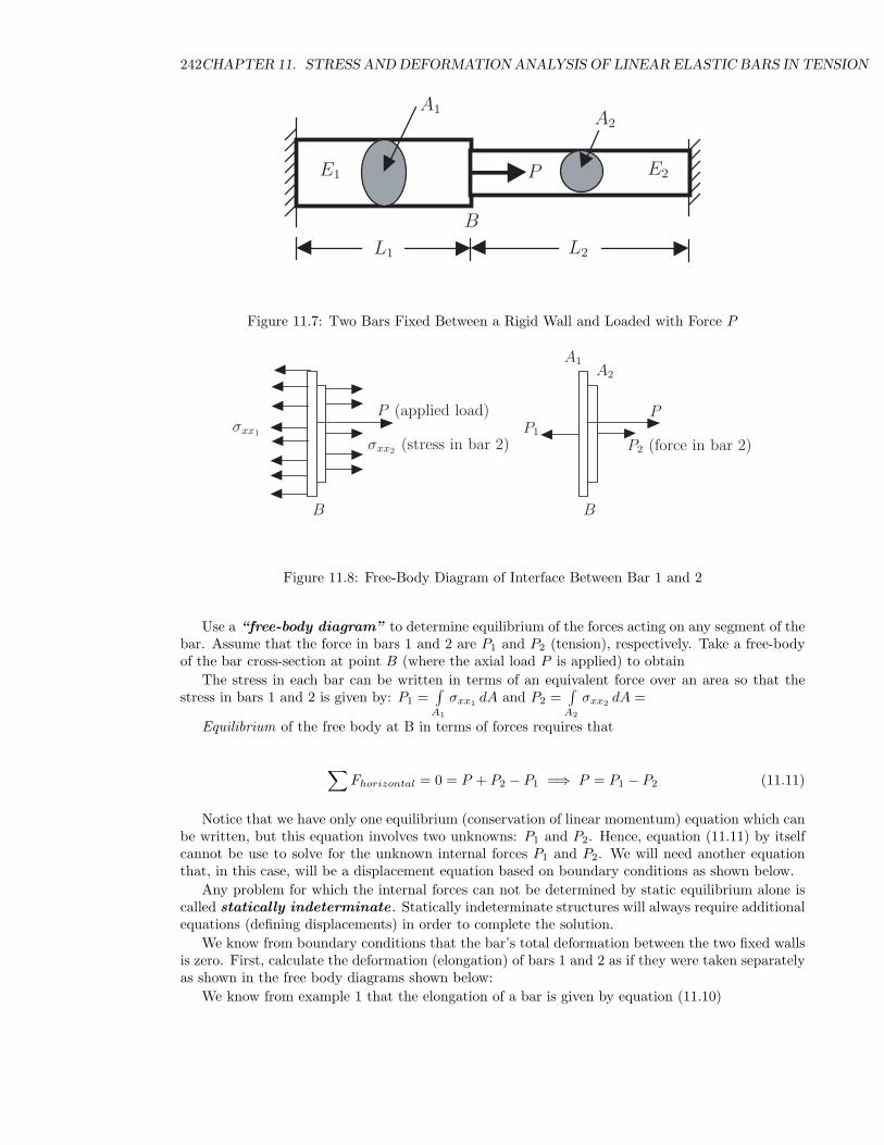
Figure 11.7: Two Bars Fixed Between a Rigid Wall and Loaded with Force P
A1A2
B
P (applied load)P1
P2 (force in bar 2)σxx1
σxx2 (stress in bar 2)
P
B
Figure 11.8: Free-Body Diagram of Interface Between Bar 1 and 2
Use a “free-body diagram” to determine equilibrium of the forces acting on any segment of thebar. Assume that the force in bars 1 and 2 are P1 and P2 (tension), respectively. Take a free-bodyof the bar cross-section at point B (where the axial load P is applied) to obtain
The stress in each bar can be written in terms of an equivalent force over an area so that thestress in bars 1 and 2 is given by: P1 =
∫A1
σxx1 dA and P2 =∫
A2
σxx2 dA =
Equilibrium of the free body at B in terms of forces requires that
∑Fhorizontal = 0 = P + P2 − P1 =⇒ P = P1 − P2 (11.11)
Notice that we have only one equilibrium (conservation of linear momentum) equation which canbe written, but this equation involves two unknowns: P1 and P2. Hence, equation (11.11) by itselfcannot be use to solve for the unknown internal forces P1 and P2. We will need another equationthat, in this case, will be a displacement equation based on boundary conditions as shown below.
Any problem for which the internal forces can not be determined by static equilibrium alone iscalled statically indeterminate . Statically indeterminate structures will always require additionalequations (defining displacements) in order to complete the solution.
We know from boundary conditions that the bar’s total deformation between the two fixed wallsis zero. First, calculate the deformation (elongation) of bars 1 and 2 as if they were taken separatelyas shown in the free body diagrams shown below:
We know from example 1 that the elongation of a bar is given by equation (11.10)

11.3. EXAMPLES OF THE 1-D AXIAL BAR PROBLEMS 243
L1 L2
A1 A2E1 E2
P1
A1A2
P1 P1 P2 P2
B
P
in bar 2)P2 (force
bar 1 bar 2interface at B
δ1 δ2
Figure 11.9: Free-Body Diagrams for Bars 1 and 2 and Their Interface
δ1 = elongation of bar 1 =P1L1
E1A1(11.12)
δ2 = elongation of bar 2 =P2L2
E2A2
Note that equations (11.12) implicitly account for equilibrium, constitutive behavior and kine-matics because they were used in deriving equation (11.10).
The displacement boundary condition for this problem requires that bars 1 and 2 together have atotal elongation of zero (since they are between two fixed walls). Thus, we can write the following:
total elongation = 0 = δ1 + δ2 =P1L1
E1A1+
P2L2
E2A2(11.13)
Solve for P1 from equation (11.13) to obtain
P1 = −E1A1
L1
(P2L2
E2A2
)(11.14)
From the equilibrium equation (11.11), substitute P2 = P1 − P into (11.14) to obtain
P1 =P
1 +(
A2E2L1A1E1L2
) (11.15)
Substitute the last result back into equilibrium (11.11) to obtain P2:
P2 =−P
1 +(
A1E1L2A2E2L1
) (11.16)
The axial stress in each bar is given by:
σxx1 =P1
A1and σxx2 =
P2
A2(11.17)
Note that the stress in the left bar is tensile (since P1 is tensile) while in the right bar the stressis compressive (since P2 is negative).

244CHAPTER 11. STRESS AND DEFORMATION ANALYSIS OF LINEAR ELASTIC BARS IN TENSION
The displacement of point B (the interface) is given by δ1 (or −δ2 since δ2 = −δ1):
δB = δ1 =P1L1
A1E1=
P (L1L2)A1E1L2 + A2E2L1
(11.18)
Consider some examples:
1) Bars are equal length, area and Young’s modulus, then P1 = −P2 = P2 and we see that each
bar carries half of the total applied load.
2) Bars are identical except A2 = A12 (bar 2 is smaller), then P1 = 2
3P (tension) and P2 = −P3
(compression) and we see that the smaller bar carries less load. The stresses are given byσxx1 = P1
A1=
23 P
A1(tension) and σxx2 = P2
A2= − 1
3 PA12
= − 23 P
A1(compression) and we see, however,
that the stresses are equal and opposite. While bar 2 carries more load, its area is larger; andwhile bar 1 carries less load, its area is larger; and consequently the stresses are equal in thebars.
3) Bars are identical except E2 = E12 (bar 2 is less-stiff), then P1 = 2
3P and P2 = −P3 and we
see that the less-stiff bar carries less load. The stresses are given by σxx1 = P1A1
=23 P
A1and
σxx2 = P2A2
= − 13 P
A12
= − 23 P
A1and we see, however, that the stresses are equal and opposite.
While bar 2 carries more load, its area is larger; and while bar 1 carries less load, its area islarger; and consequently the stresses are equal in the bars. Looking at equations (11.14) and(11.16), changing the modulus ratio E2
E1has the same effect as changing the area ratio A2
A1, i.e.,
we can halve the area of bar 2 or the modulus of bar 2 and the result is same in the amountof force carried by each bar.
Example 11-3
Two elastic bars in parallel. Each bar has different properties A, E and L as shown. Thehorizontal bar is rigid and remains horizontal when load is applied.
1 2A rigid horizo nta l bar isattached to the botto mof each vertica l bar. Thehorizonta l bar rema inshorizonta l when p ulleddow nward
A1 , E1 , L1 A2 , E2 , L2
P
Figure 11.10: Two Parallel Bars
Determine: Force, stress and deflection in each bar.As before, we have the four governing equations that must be satisfied: Equilibrium, Constitutive,
Kinematics and Boundary Conditions. Assume that the axial force in bars 1 and 2 are P1 and P2
(tension), respectively. Use a “free-body diagram” to determine equilibrium of the forces actingin each bar. Take a free-body by cutting each bar below its fixed point:

11.3. EXAMPLES OF THE 1-D AXIAL BAR PROBLEMS 245
A1 , E1 , L1A2 , E2 , L2
P1P2
P
1 2
Figure 11.11: Free-Body for Two Parallel Bar System
Equilibrium of the free body in terms of forces requires that
∑Fvertical = 0 = P1 + P2 − P =⇒ P = P1 − P2 (11.19)
The elongation of each bar is given
δ1 = elongation of bar 1 =P1L1
E1A1(11.20)
δ2 = elongation of bar 2 =P2L2
E2A2
As stated in the previous example, equations (11.20) implicitly account for equilibrium, consti-tutive behavior and kinematics because they were use in deriving equation (11.10).
Assume the horizontal bar moves down a distance δ when the load P is applied. Since thehorizontal bar is required to remain horizontal, then the elongation of each of the vertical bars mustbe equal to the movement δ of the horizontal bar. Thus our displacement boundary condition canbe written:
δ1 = δ2 = δ =(
movement ofhorizontal bar
)=
P1L1
E1A1=
P2L2
E2A2(11.21)
We now have two equations [(11.19) and (11.21)] and two unknowns (P1 and P2). Writing thetwo equations in matrix notation:
[1 1L1
(A1E1)− L2
(A2E2)
] {P1
P2
}=
{P0
}(11.22)
Solving for P1 and P2 from the above gives

246CHAPTER 11. STRESS AND DEFORMATION ANALYSIS OF LINEAR ELASTIC BARS IN TENSION
P1 =
∣∣∣∣ P 10 − L2
(A2E2)
∣∣∣∣∣∣∣∣ 1 1L1
(A1E1)− L2
(A2E2)
∣∣∣∣=
PL2(A2E2)
L2(A2E2)
+ L1(A1E1)
=P
1 +(
A2E2L1A1E1L2
) (11.23)
P2 =
∣∣∣∣ 1 PL1
(A1E1)0
∣∣∣∣∣∣∣∣ 1 1L1
(A1E1)− L2
(A2E2)
∣∣∣∣=
P
1 +(
A1E1L2A2E2L1
) (11.24)
Stress in each bar is given by
σ1 =P1
A1=
PA1
1 +(
A2E2L1A1E1L2
) (11.25)
σ2 =P2
A2=
PA2
1 +(
A1E1L2A2E2L1
) (11.26)
The deflection of each bar is equal and given by substituting P1 or P2 into (11.21) to obtain
δ1 =(
P1L1
A1E1
)= δ2 =
PL1L2
A1E1L2 + A2E2L1(11.27)
Consider some examples:
1) Bars are equal length, area and Young’s modulus, then P1 = P2 = P2 (tension) and we see
that each bar carries half of the total applied load.
2) Bars are identical except A2 = A12 (bar 2 is smaller), then P1 = 2
3P (tension) and P2 = P3
(tension) and we see that the smaller bar carries less load. The stresses are given by σxx1 =P1A1
=23 P
A1and σxx2 = P2
A2=
13 PA12
=23 P
A1and we see, however, that the stresses are equal and in
tension. While bar 1 carries more load, its area is larger; and while bar 2 carries less load, itsarea is smaller; and consequently the stresses are equal in the bars.
Example 11-4
Uniaxial elastic bar subjected to a uniform temperature increase of ∆T :The bar is fixed between two wall and has a constant cross-section A.Determine: axial strain and stress in the bar and the force on the wall.For this problem, we have 4 governing equations to satisfy:Equilibrium: ∂σxx
∂x = 0Constitutive (Stress-Strain): σxx = Eεelastic
xx
Kinematics: εtotalxx = εelastic
xx + εthermalxx , εthermal
xx = α∆T , and εtotalxx = ∂ux
∂x = axial strainmeasured/observed (e.g., by a strain gage)
Boundary Conditions: ux(x = 0) = 0 & ux(x = L) = 0 or εtotalxx = ∂ux
∂x = 0
Solution
1) εtotalxx = ∂ux
∂x = 0
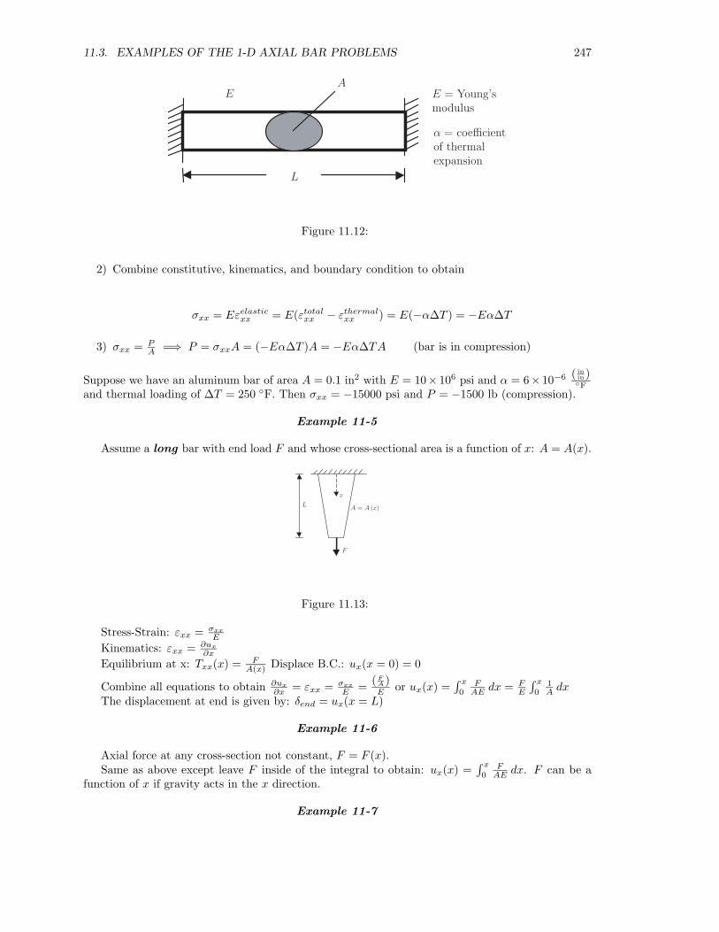
11.3. EXAMPLES OF THE 1-D AXIAL BAR PROBLEMS 247
EA
L
E = Young’smodulus
α = coefficientof thermalexpansion
Figure 11.12:
2) Combine constitutive, kinematics, and boundary condition to obtain
σxx = Eεelasticxx = E(εtotal
xx − εthermalxx ) = E(−α∆T ) = −Eα∆T
3) σxx = PA =⇒ P = σxxA = (−Eα∆T )A = −Eα∆TA (bar is in compression)
Suppose we have an aluminum bar of area A = 0.1 in2 with E = 10× 106 psi and α = 6× 10⁻⁶ ( inin )◦F
and thermal loading of ∆T = 250 ◦F. Then σxx = −15000 psi and P = −1500 lb (compression).
Example 11-5
Assume a long bar with end load F and whose cross-sectional area is a function of x: A = A(x).
A = A (x)
x
F
L
Figure 11.13:
Stress-Strain: εxx = σxx
E
Kinematics: εxx = ∂ux
∂x
Equilibrium at x: Txx(x) = FA(x) Displace B.C.: ux(x = 0) = 0
Combine all equations to obtain ∂ux
∂x = εxx = σxx
E = (FA )E or ux(x) =
∫ x
0F
AE dx = FE
∫ x
01A dx
The displacement at end is given by: δend = ux(x = L)
Example 11-6
Axial force at any cross-section not constant, F = F (x).Same as above except leave F inside of the integral to obtain: ux(x) =
∫ x
0F
AE dx. F can be afunction of x if gravity acts in the x direction.
Example 11-7

248CHAPTER 11. STRESS AND DEFORMATION ANALYSIS OF LINEAR ELASTIC BARS IN TENSION
A = A (x)
x
LF = F (x)(units offorce/length)
Figure 11.14:
x
px = px (x)
ux = ux (x)
Figure 11.15:
P (x) px (x) P (x + ∆x)
x ∆x x + ∆x
Figure 11.16:
A distributed axial load px(x) [units of forcelength ] is applied to an axial bar as shown below:
In order to obtain the equilibrium equation, consider a free-body of the bar at point x as shownbelow. Assume the force in the bar at point x is P (x) and at x + ∆x is P (x + ∆x).
For equilibrium in x direction:
P (x + dx) − P (x) + px dx = 0.
Divide by dx and take limit to obtain the equilibrium equation:
∂P
∂x+ px = 0 (11.28)
Recall P = σxxA = (Eεxx)A = EA∂ux
∂x . Substitute P into the equilibrium equation to obtainthe equilibrium equation in terms of axial displacement:
∂
∂x
(EA
∂ux
∂x
)+ px = 0 (11.29)

11.3. EXAMPLES OF THE 1-D AXIAL BAR PROBLEMS 249
Example 11-8
The concrete pier of square cross section is 8 m high. The sides taper uniformly from a width of0.5 m at the top to 1.0 m at the bottom. Determine the shortening of this pier due to the compressiveload shown. Take the modulus of elasticity of concrete as 2 × 10¹⁰ N
m3 .
2 × 10⁶
0.5 m
1 m
8 m
x
Figure 11.17:
Solution
We use the general solution presented in Example 11.6: ux(x) =∫ x
0P (x)
EA(x) dx which should bereasonable for an angle of taper of 18◦.
Let the width of the pier be w(x) at any distance x from the bottom, then A(x) = w2(x).Note that w = 1 m at x = 0 and w = 0.5 m at x = 8. Since the side is a straight line, then the
width varies linearly with x. Assume the width is given by w(x) = ax + b. To solve for a and b, seuse the known width at x = 0 and x = 8 to obtain b = 1 and a = −0.0625. Hence,
w(x) = −0.0625x + 1 mA(x) = (1 − 0.0625x)2 m2
Now P (x) is constant throughout the pier (neglecting gravity) so that P = 2×10⁶ N. SubstitutingP , E and A(x) into the displacement equation gives:
∴ ux(x) =∫ x
0
2 × 10⁶
2 × 10¹⁰(1 − 0.0625x)2dx (units of m)
= 10−4
∫ x
0
1(1 − 0.0625x)2
dx =10−4
(0.0625)
[(−1)(−0.0625)1 − 0.0625x
]L
0
=10−4
(0.0625)(−0.0625)
[1 − 1
1 − 0.0625L
]
Shortening of pier = −ux(x = L) = − (10−4)0.0625 (−0.0625)
[1 − 1
0.5
]= 6.25 × 10⁻⁴ cm = 0.16 cm
Example 11-9
Given: A prismatic bar of length 10 ft and cross-section area of 6 in2 , carries a distributed axialload of 5 lb
ft and end load of 3000 lb. as shown:Required : Determine Young’s Modulus so that the bar will elongate:
a) No more than 2 inches

250CHAPTER 11. STRESS AND DEFORMATION ANALYSIS OF LINEAR ELASTIC BARS IN TENSION
3,000 lb.
10 ft
5 lb/ft
Figure 11.18:
x
Figure 11.19:
b) No more than 0.5 inch
Solution
d
dx
(AE
dux
dx
)= −px
AEdux
dx= − 5
12x + c1
dux
dx= − 5
6(12)Ex +
c1
6(E)
ux(x) = − 5x2
144E+
c1x
6E+ c2
AEdux
dx(x = 120) = 3000 =− 5
12 (120) + c1
3050 = c1
ux(x = 0) = 0 = c2
ux(x) = − 5144
x2
E+
3050x
6E
a) ux(120) = 2 in. 2 = − 5144
(120)2
E + 3050(120)6E =⇒ E ≥ 30250 psi
b) ux(120) = 0.5 in. 0.5 = − 5144
(120)2
E + 3050(120)6E =⇒ E ≥ 121000 psi
Example 11-10
Given: A rod as shown:Assume:
1) Mass density ρ = 5000 kgm3

11.3. EXAMPLES OF THE 1-D AXIAL BAR PROBLEMS 251
10 m
0.05 cm
x
Figure 11.20:
2) E = 150 × 109 Pa
Required : Determine the elongation of the rod due to its own weight.Solution:
10 m
0.05 cm
x
Figure 11.21:
W = ρVg = ρAhg =⇒ W (x) = ρAgx
W = 5000(9.8)Ax
W = 49000Ax
d
dx
(AE
dux
dx
)= −gx = ρAg
AEdux
dx= ρAgx + c1
B.C.
AEdux
dx(x = 10) = W (x = 10) = ρAg(10) + c1 = ρAg(10)
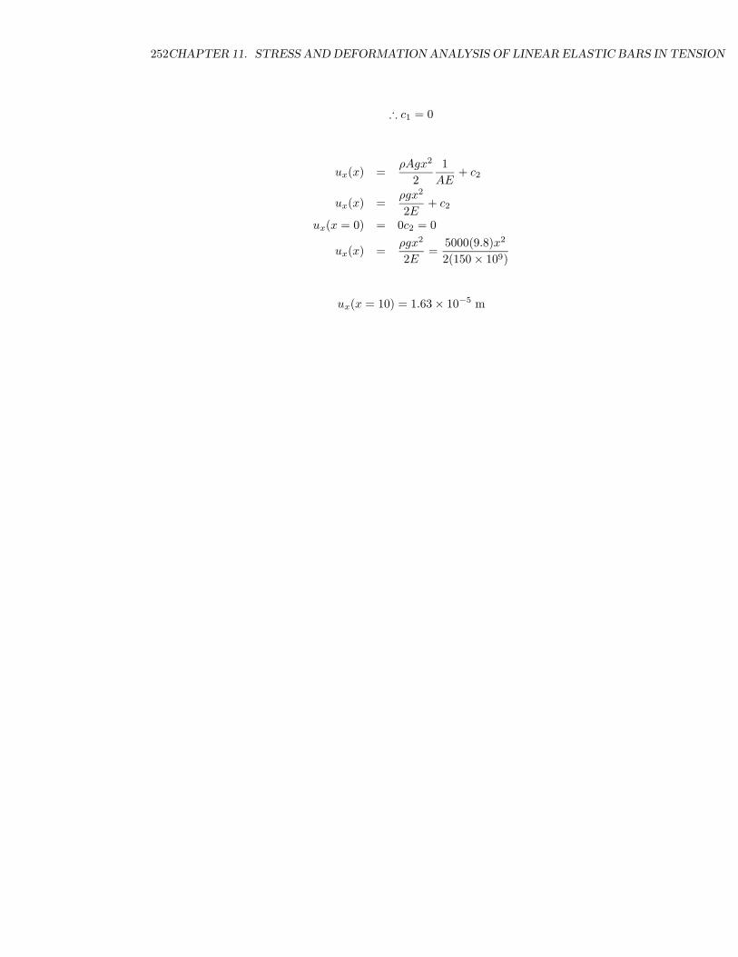
252CHAPTER 11. STRESS AND DEFORMATION ANALYSIS OF LINEAR ELASTIC BARS IN TENSION
∴ c1 = 0
ux(x) =ρAgx2
21
AE+ c2
ux(x) =ρgx2
2E+ c2
ux(x = 0) = 0c2 = 0
ux(x) =ρgx2
2E=
5000(9.8)x2
2(150 × 109)
ux(x = 10) = 1.63 × 10⁻⁵ m

11.3. EXAMPLES OF THE 1-D AXIAL BAR PROBLEMS 253
Deep Thought
Some people go a little too far in their studyof elasticity.

254CHAPTER 11. STRESS AND DEFORMATION ANALYSIS OF LINEAR ELASTIC BARS IN TENSION
11.4 Questions
11.1 Consider the stress tensor for uniaxial load. If a load is applied in the x direction, then findthe components of the stress tensor? Use a symbolic variable for those components of stress,which are not zero and use a 3 × 3 matrix array.
11.2 Compute the strain tensor for the elastic bar under uniaxial load in 11.1 indicating the compo-nents in terms of strain variable. Specify the differences between the stress and strain tensor.
11.5 Problems
11.3 GIVEN : A prismatic bar is loaded as shown:
2.5 kN/m
15 kN
5 m
Problem 11.3
ASSUME : Cross sectional area, A = 6 in2
REQUIRED : Determine the Young’s Modulus so that the bar will elongate:
a) No more than 2 inches
b) No more than .5 inch
11.4 GIVEN : A prismatic bar is loaded as shown below.
4 m
5000 N
Problem 11.4
ASSUME : Cross-sectional area of 25 cm2.
REQUIRED : Determine the necessary Young’s modulus such that the bar will deflect no morethan 0.01 m.
11.5 GIVEN : A prismatic bar is loaded as shown below.
ASSUME : The bar is made of steel with E = 29 × 106 psi.
REQUIRED :
a) Determine the necessary cross-sectional area such that the bar will deflect no more than0.01 in.

11.5. PROBLEMS 255
10 ft20,000 lb
Problem 11.5
b) Determine the axial stress and strain in the bar. If the steel “yields” (becomes inelastic)at 30,000 psi of stress, should we be concerned about possible failure and why?
11.6 For the given data, compute the following:
a) Horizontal displacement of point B on the bar.
b) Stress and strain in each bar.
15,000 N
50 cm 30 cm
Section A: SteelCross Sectional Area=2.5 cm2
E = 200 GPaSection B : AluminumArea = 1.5 cm2
E = 70 GPaBA
40,000 N
Problem 11.6
11.7 GIVEN : The configuration below shows two parallel bars with different properties. The ver-tical bar to which the force is applied is rigid and constrained to remain vertical.
F
Material 1
Material 2
Problem 11.7
256CHAPTER 11. STRESS AND DEFORMATION ANALYSIS OF LINEAR ELASTIC BARS IN TENSION
L1 = L2 = 10 mE1 = 10 GPaE2 = 50 GPaA1 = 2 cm2
A2 = 4 cm2
σ1y = 35 MPa
σ2y = 100 MPa
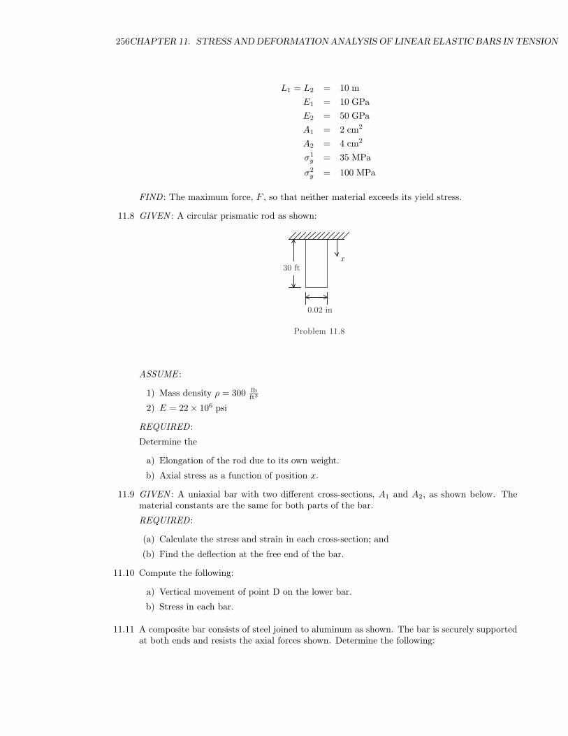
FIND : The maximum force, F , so that neither material exceeds its yield stress.
11.8 GIVEN : A circular prismatic rod as shown:
x30 ft
0.02 in
Problem 11.8
ASSUME :
1) Mass density ρ = 300 lbft3
2) E = 22 × 106 psi
REQUIRED :
Determine the
a) Elongation of the rod due to its own weight.
b) Axial stress as a function of position x.
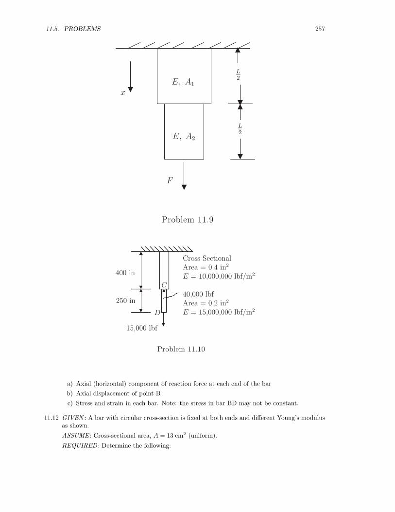
11.9 GIVEN : A uniaxial bar with two different cross-sections, A1 and A2, as shown below. Thematerial constants are the same for both parts of the bar.
REQUIRED :
(a) Calculate the stress and strain in each cross-section; and
(b) Find the deflection at the free end of the bar.
11.10 Compute the following:
a) Vertical movement of point D on the lower bar.
b) Stress in each bar.
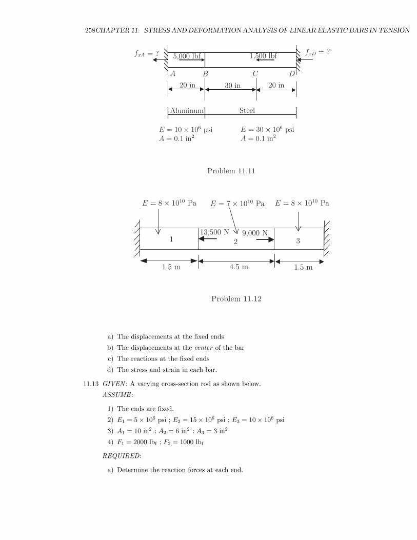
11.11 A composite bar consists of steel joined to aluminum as shown. The bar is securely supportedat both ends and resists the axial forces shown. Determine the following:
11.5. PROBLEMS 257
E, A1
E, A2
L2
x
F
L2
Problem 11.9
Cross SectionalArea = 0.4 in2
E = 10,000,000 lbf/in2
40,000 lbfArea = 0.2 in2
E = 15,000,000 lbf/in2
250 in
400 in
15,000 lbf
D
C
Problem 11.10
a) Axial (horizontal) component of reaction force at each end of the barb) Axial displacement of point Bc) Stress and strain in each bar. Note: the stress in bar BD may not be constant.
11.12 GIVEN : A bar with circular cross-section is fixed at both ends and different Young’s modulusas shown.
ASSUME : Cross-sectional area, A = 13 cm2 (uniform).
REQUIRED : Determine the following:
258CHAPTER 11. STRESS AND DEFORMATION ANALYSIS OF LINEAR ELASTIC BARS IN TENSION
fxA fxD = ?
Steel
E = 30 × 106 psiA = 0.1 in2
20 in30 in20 in
= ?
A B C D
E = 10 × 106 psiA = 0.1 in2
Aluminum
5,000 lbf 1,500 lbf
Problem 11.11
E = 8 × 10¹⁰ PaE = 7 × 10¹⁰ Pa
1.5 m4.5 m
E = 8 × 10¹⁰ Pa
1.5 m
13,500 N 9,000 N1 2 3
Problem 11.12
a) The displacements at the fixed ends
b) The displacements at the center of the bar
c) The reactions at the fixed ends
d) The stress and strain in each bar.
11.13 GIVEN : A varying cross-section rod as shown below.
ASSUME :
1) The ends are fixed.
2) E1 = 5 × 10⁶ psi ; E2 = 15 × 106 psi ; E3 = 10 × 106 psi
3) A1 = 10 in2 ; A2 = 6 in2 ; A3 = 3 in2
4) F1 = 2000 lbf ; F2 = 1000 lbf
REQUIRED :
a) Determine the reaction forces at each end.

11.5. PROBLEMS 259
F1 F2A
12 in 18 in 8 in
1. 2. 3.
x
Problem 11.13
b) Determine the displacements at each end.
c) Displacement at point A
d) Stress and strain in each bar.
11.14 GIVEN : A column support for a bridge as shown:
10 in
10 ft
16 in
12,000 lbf
Problem 11.14
ASSUME :

260CHAPTER 11. STRESS AND DEFORMATION ANALYSIS OF LINEAR ELASTIC BARS IN TENSION
1) Square cross-section
2) EL = 12 × 106 psi
REQUIRED : Determine the displacement at:
a) The bottom of the support
b) The middle of the support
c) The top of the support
Hint:∫
(a + bx)ndx = (a+bx)n+1
(n+1)b for n �= −1
11.15 GIVEN : A wedge-shaped aluminum part as shown below which is fixed from movement at itsupper surface.
25 in
50 ft
10 in
ρ = 0.100 lbm/in3
E = 10.5 × 10⁶ psi
Problem 11.15
ASSUME :
1) ρ = 0.100 lbmin3
2) E = 10.5 × 10⁶ psi
REQUIRED : Determine the elongation of the part due to its own weight.
Hint: Consider gravity and determine weight as a function of vertical position.
11.16 GIVEN : Two vertical prismatic rods as shown below horizontally suspend a stiff bar of neg-ligible weight. One of the rods is made of steel with a Young’s modulus of 30 × 106 psi anda length of 5 ft while the other is made of brass with a Young’s modulus 14 × 106 psi and alength of 10 ft.
REQUIRED : In order for the bar to remain horizontal, where must a load of 8000 lbf be placed(i.e., position x)? Assume the bars behave elastically and that the bending of the horizontalbar is negligible.

11.5. PROBLEMS 261
BrassSteel
10 ft
5 ft
12 ft
x
8000 lbf
Problem 11.16
11.17 A load P = 1000 N is applied to bar #1 at point A according to the diagram shown below.The horizontal bar is rigid and remains horizontal when the load is applied. Considering thatonly vertical displacement is allowed determine the following:
a) The reaction forces at points D and F.
b) The displacements of points C and A.
c) The strain in each bar (1, 3 & 4).
d) The stress in each bar (1, 3 & 4).
11.18 In order to complete the design for the press shown below; determine the required crosssectional area of element #3. The properties for the elements are given as follows: Elements#1 and #2 are made of steel (elastic modulus of 200 GPa) while element #3 is made ofaluminum (elastic modulus of 70 GPa). The cross sectional area for element #1 is 2.0 cm2
while for #2 is 2.5 cm2. Finally, the length of element #1 is 15 cm and 25 cm for elements#2 and #3. The 100 kN force is applied to the end of bar 1.
Note: Observe that the plate connecting all elements is constrained so that no rotation isallowed (i.e. it maintains a horizontal position at all times). Also note that the load P isapplied directly to element #1.
11.19 For the design problem stated above in 11.18, if all elements have a square cross section, thencalculate the selected width of element #3. Also calculate the corresponding strain and stressacting on each element.
11.20 GIVEN : A bar with cross-sectional area A = 5 in2 of is loaded as shown:
REQUIRED : Determine the Young’s Modulus of the bar material so that the bar will elongate:
a) No more than 2 inches.
b) No more than 0.2 inches.
c) For and Young’s Modulus of 106 psi, find P (x), u(x), and σxx(x).
d) For and Young’s Modulus of 106 psi, plot P (x), u(x), and σxx(x).

262CHAPTER 11. STRESS AND DEFORMATION ANALYSIS OF LINEAR ELASTIC BARS IN TENSION
Bar #1: AluminumE = 70 GPaArea = 0.0002 m2
Length = 30 cmBar #3: SteelE = 200 GPaArea = 0.0002 m2
Length = 20 cmBar #4: AluminumE = 70 GPaArea = 0.0002 m2
Length = 50 cm
A
B
C
D
E
F
P
1
34
Problem 11.17
32
1
P = 100 kN
Problem 11.18
11.21 GIVEN : A bar with cross-sectional area A = 5 in2 is loaded as shown:
REQUIRED : For a Young’s Modulus of 106 psi:
a) Find P (x), u(x), and σxx(x).
b) Plot P (x), u(x), and σxx(x).
11.22 GIVEN : A bar with cross-sectional area of A = 5 in2 is loaded as shown:
REQUIRED : For a Young’s Modulus of 106 psi:
a) Find P (x), u(x), and σxx(x).
b) Plot P (x), u(x), and σxx(x).

11.5. PROBLEMS 263
Problem 11.20
Problem 11.21
Problem 11.22
11.23 GIVEN : A concrete column support for a bridge as shown to the right:
ASSUME :
1) Square cross-section
2) E = 4.5 × 10⁶ psi and ρ = 2242 kgm3
REQUIRED : Determine the displacement at:
a) The bottom of the support
b) The middle of the support

264CHAPTER 11. STRESS AND DEFORMATION ANALYSIS OF LINEAR ELASTIC BARS IN TENSION
10 ft
12 in
10,000 lb
yx
8 in
Problem 11.23
c) The top of the support
Useful formula:∫
(a + bx)ndx = (a+bx)n+1
(n+1)b for n �= −1
11.24 GIVEN : Joe’s Restaurant sign as shown below:
Problem 11.24
In this problem, gravity cannot be neglected. Note: mixed units. Work problem in metricunits.
ASSUME : All four bars are cylindrical and:
1) The concrete base has a maximum radius of 2’ and a minimum radius of 1’.
2) The steel inverted base has a maximum radius of 1.3’ and a minimum radius of 6”.

11.5. PROBLEMS 265
REQUIRED :
a) Find P (x), ux(x), and σxx(x) in the concrete base. P (x) is the internal axial force.
b) Plot P (x), ux(x), and σxx(x) in the concrete base.

266CHAPTER 11. STRESS AND DEFORMATION ANALYSIS OF LINEAR ELASTIC BARS IN TENSION