REDESIGN OF MOTORCYCLE REAR SUSPENSION WITH CAD TECHNOLOGY · PDF fileREDESIGN OF MOTORCYCLE...
6
REDESIGN OF MOTORCYCLE REAR SUSPENSION WITH CAD TECHNOLOGY ПРЕПРОЕКТИРОВАНИЕ ПОДВЕШИВАНИЯ МОТОЦИКЛА ПРИ ПОМОЩИ CAD ТЕХНОЛОГИИ Prof. M.Sc. Božič S. 1 , Prof. Gombač E. 2 , Prof. Harmel A. 3 School Center Postojna 1,2,3 , The Faculty of Maritime Studies and Transport 1 , Slovenia Abstract: The automotive industry is constantly looking for new ways to reduce fuel consumption. This is not only an individual concern for the car and motorcycle customer but also an environmental question on a more global level. When it comes to meeting these environmental requirements, the contribution from body design and manufacturing engineers lies in the field of weight savings. In the contribution, a design of aluminium rear suspension for motorcycle, made with CATIA V5 R14 computer aided design advanced program, is presented. Investigation of a tension – deformation analysis of this suspension is performed with the finite element method (FEM) simulation. KEYWORDS: AUTOMOTIVE INDUSTRY, MOTORCYCLE REAR SUSPENSION, ALUMINIUM ALLOYS, PROTOTYPE, FEM ANALYSIS 1. Introduction Nowadays, aluminium alloys are used in many applications in which the combination of high strength and low weight is attractive. Automotive and motorcycle industry is one area in which the low weight can be of significant value. Modern, fast transport systems are generally synonymous with lightweight structures, frequently made of aluminium. Weight savings result in reduced fuel consumption, higher speeds, higher payloads and a reduced environmental impact, but an effective structural system also imposes heavy demands when it comes to the strength of the material and its formability, ease of joining, surface treatment, energy absorption in the event of impact, corrosion resistance and so on. Building and/or modifying motorcycle chassis or parts is a serious undertaking and the consequences of mechanical failure can result in serious injury. Some of the practices and designs outlined may be dangerous unless implemented by skilled and experienced people who have qualifications in engineering, design and fabrication. Design against failure is a complex, multifaceted process, in which we need to examine each facet separately for its influence on the eventual successful avoidance of failure in our design [1]. In a motorcycle chassis, we are seldom concerned with solid bars but mostly with round tubes. To maintain the same bending and torsion stiffness with a less dense tube material, we can either keep the diameter the same and increase the tube thickness or (more efficiently) keep the thickness the same and increase the diameter. Between the two extremes is a wide choice of proportions. If we increase the tube diameter and use the same wall thickness, we find that an aluminium tube needs approximately twice the diameter of a steel one but would weigh only 70 per cent as much. Thus the most efficient way to use light-weight materials is to make the sections as large as possible consistent with maintaining a practical wall thickness. But, in maintaining similar structural characteristics to those of steel, our light alloy tube will weigh more than a simple comparison of density indicates. The density of aluminium is 33 % that of steel but the structural weights of our bar and tube in the foregoing examples are 58 and 70 % respectively. Figure 1 is a schematic view of the design process for a generic engineering component. The failure focus identifies the type or mode of failure the designer will focus on, or specifically design against, given the material, characteristics and the operation condition of the component. Modern, fast transport systems are generally synonymous with lightweight structures, frequently made of aluminium. Weight savings result in reduced fuel consumption, higher speeds, higher payloads and a reduced environmental impact, but an effective structural system also imposes heavy demands when it comes to the strength of the material and its formability, ease of joining, surface treatment, energy absorption in the event of impact, corrosion resistance and so on. Different steps can be taken to improve fuel efficiency and reduce toxic emissions, but the large contribution today still comes from the field of weight saving. The largest weight savings can be achieved if materials selection, body concept and joining methods are developed in an integrated process. Aluminium is a natural candidate due to its low specific weight and good recyclability. Different aluminium alloys which are appearing in different shapes, such as sheets, extrusions, castings and hydro- formed parts, will have to be joined together. There is no question that the use of aluminium is increasing within the welding fabrication industry. Manufacturers often adopt this material either through innovation, or as a result of pressure applied by their end users. Engineering component Failure focus Design choices Operating condition Figure 1: The designers focus in component design 2. Introducing engineering materials Fatigue life prediction techniques play an ever-expanding role in the design of components in the ground vehicle industry. Motorcycle industries increasingly seek to reduce development times while simultaneously achieving higher quality levels for their vehicles. One of the essential elements in achieving these targets is durability analysis. By definition, durability is the capacity of an item to survive its intended use for a suitably long period of time. Therefore, good durability minimizes the cost of maintaining and replacing the item, prevention of failures, and optimizes the motorcycle or component design. Procedures used by the motorcycle industry to perform fatigue design are continually evolving. The main task performed during durability analysis is the fatigue life assessment of components, such as engine parts, suspension parts, and body structures. 12
Transcript of REDESIGN OF MOTORCYCLE REAR SUSPENSION WITH CAD TECHNOLOGY · PDF fileREDESIGN OF MOTORCYCLE...

REDESIGN OF MOTORCYCLE REAR SUSPENSION WITH CAD TECHNOLOGY
ПРЕПРОЕКТИРОВАНИЕ ПОДВЕШИВАНИЯ МОТОЦИКЛА ПРИ ПОМОЩИ CAD
ТЕХНОЛОГИИ
Prof. M.Sc. Božič S.1, Prof. Gombač E.2, Prof. Harmel A.3School Center Postojna 1,2,3, The Faculty of Maritime Studies and Transport 1, Slovenia
Abstract: The automotive industry is constantly looking for new ways to reduce fuel consumption. This is not only an individual concern for the car and motorcycle customer but also an environmental question on a more global level. When it comes to meeting these environmental requirements, the contribution from body design and manufacturing engineers lies in the field of weight savings. In the contribution, a design of aluminium rear suspension for motorcycle, made with CATIA V5 R14 computer aided design advanced program, is presented. Investigation of a tension – deformation analysis of this suspension is performed with the finite element method (FEM) simulation. KEYWORDS: AUTOMOTIVE INDUSTRY, MOTORCYCLE REAR SUSPENSION, ALUMINIUM ALLOYS, PROTOTYPE, FEM ANALYSIS
1. Introduction
Nowadays, aluminium alloys are used in many applications in which the combination of high strength and low weight is attractive. Automotive and motorcycle industry is one area in which the low weight can be of significant value. Modern, fast transport systems are generally synonymous with lightweight structures, frequently made of aluminium. Weight savings result in reduced fuel consumption, higher speeds, higher payloads and a reduced environmental impact, but an effective structural system also imposes heavy demands when it comes to the strength of the material and its formability, ease of joining, surface treatment, energy absorption in the event of impact, corrosion resistance and so on. Building and/or modifying motorcycle chassis or parts is a serious undertaking and the consequences of mechanical failure can result in serious injury. Some of the practices and designs outlined may be dangerous unless implemented by skilled and experienced people who have qualifications in engineering, design and fabrication. Design against failure is a complex, multifaceted process, in which we need to examine each facet separately for its influence on the eventual successful avoidance of failure in our design [1]. In a motorcycle chassis, we are seldom concerned with solid bars but mostly with round tubes. To maintain the same bending and torsion stiffness with a less dense tube material, we can either keep the diameter the same and increase the tube thickness or (more efficiently) keep the thickness the same and increase the diameter. Between the two extremes is a wide choice of proportions. If we increase the tube diameter and use the same wall thickness, we find that an aluminium tube needs approximately twice the diameter of a steel one but would weigh only 70 per cent as much. Thus the most efficient way to use light-weight materials is to make the sections as large as possible consistent with maintaining a practical wall thickness. But, in maintaining similar structural characteristics to those of steel, our light alloy tube will weigh more than a simple comparison of density indicates. The density of aluminium is 33 % that of steel but the structural weights of our bar and tube in the foregoing examples are 58 and 70 % respectively. Figure 1 is a schematic view of the design process for a generic engineering component. The failure focus identifies the type or mode of failure the designer will focus on, or specifically design against, given the material, characteristics and the operation condition of the component. Modern, fast transport systems are generally synonymous with lightweight structures, frequently made of aluminium. Weight savings result in reduced fuel consumption, higher speeds, higher payloads and a reduced environmental impact, but an effective structural system also imposes heavy demands when it comes to the strength of the material and its formability, ease of joining, surface treatment, energy absorption in the event of impact, corrosion resistance and so on. Different steps can be taken to improve fuel
efficiency and reduce toxic emissions, but the large contribution today still comes from the field of weight saving. The largest weight savings can be achieved if materials selection, body concept and joining methods are developed in an integrated process. Aluminium is a natural candidate due to its low specific weight and good recyclability. Different aluminium alloys which are appearing in different shapes, such as sheets, extrusions, castings and hydro-formed parts, will have to be joined together. There is no question that the use of aluminium is increasing within the welding fabrication industry. Manufacturers often adopt this material either through innovation, or as a result of pressure applied by their end users.
Engineering component
Failure focus
Des
ign
choi
ces
Operating condition
Figure 1: The designers focus in component design
2. Introducing engineering materials
Fatigue life prediction techniques play an ever-expanding role in the design of components in the ground vehicle industry. Motorcycle industries increasingly seek to reduce development times while simultaneously achieving higher quality levels for their vehicles. One of the essential elements in achieving these targets is durability analysis. By definition, durability is the capacity of an item to survive its intended use for a suitably long period of time. Therefore, good durability minimizes the cost of maintaining and replacing the item, prevention of failures, and optimizes the motorcycle or component design. Procedures used by the motorcycle industry to perform fatigue design are continually evolving. The main task performed during durability analysis is the fatigue life assessment of components, such as engine parts, suspension parts, and body structures.
12

Motorcycle manufacturers have made large investments in this area so as to achieve products which meet a specified fatigue life target. In the applications where defects are avoided by careful selection of materials and quality fabrication, coupled with quality control, a crack growth analysis may underestimate actual service lives significantly. Crack initiation analysis is best suited for these cases. The crack initiation approach involves two operations which convert the load history, component geometry, and material input.
2.1. Engineering materials Materials are chosen for a variety of reasons but generally three dominant criteria are used in the selection process: first of all, the material must meet the specified duty for the product (strength, elasticity or wear resistance for example); secondly, the material must be readily available. Material suppliers are notorious for listing exotic products which can only be produced if the buyer is prepared to wait many months or is prepared to order a large tonnage; thirdly the material must meet production requirements. The product must be capable of being produced. It may be exciting to design a product in a special ceramic, but the excitement soon evaporates when it is discovered that the only furnace capable of producing the desired manufacturing conditions is in some remote location, or has inadequate capacity. Ultimately, material selection is determined in consultation with the producer or distributor of the materials concerned. This will ensure that our material specification for the design is up-to-date. The alloys of aluminium are particularly useful due to their corrosion resistance, malleability and fluidity in casting applications. High strength to weight ratios available with aluminium makes these alloys particularly useful in the aerospace industry. Hardening of the alloy may be achieved by either heat treatment, followed by ageing, or by cold working, resulting in strain hardening. Aluminium maybe cast, rolled, extruded, forged, spun or shot-peen deformed. Shot peening is a process in which small metal balls (shot), of a mixed size are blown in a high-pressure air stream against the surface, thereby impact-loading and flowing the material by plastic-deformation at the surface of the component. Apart from steels, aluminium is the single most useful structural metal. However, aluminium is particularly susceptible to galvanic corrosion and stress corrosion. Particular care is needed in applications where aluminium in contact with other metals may be exposed to an electrolyte (e.g. saltwater).
2.2 Material selection On current estimates the number of available material choices for engineering components range between 40,000 to 80,000. Selecting the right material for a specific design is probably the single most important decision facing designers. Unless other constraining factors point the way to a particular choice the following recipe will generally result in a short list of hopefuls from the ocean of materials: Will it work? The answer to this question rests with the matching of dominant or primary criteria, such as strength, hardness, elastic behaviour (tensile or shear module), hardenability, toughness, magnetic properties, thermal and electrical conductivity; Will it last? This question is answered by the important criteria of corrosion and heat resistance, as well as resistance to wear, dynamic loading, shock, creep and stress corrosion; Can it be made? This question refers to castability, machinability and surface finish performance or surface enhancement, such as coating, plating and anodizing; Can it be done within specified limits? The main constraints of most engineering components or structures are cost and weight. For these constraints to be met the designer needs a feel for relative costs and relative weights. There are many formal sources available for material selection in hard copy (texts and standards), software (material selector expert
systems) and manufacturers' catalogues. In selecting the correct material for any given application, it is expected that designers develop some wisdom about the parametric nature of material choices in design. Typical design parameters are strength to weight ratio (Sγ / ρ), in mass limited designs, and stiffness to weight ratio (E/ρ) in designs where structural deflection and mass are both limiting design constraints. It is this type of parametric design that forms the basis of several of the expert systems used in material selection software.
3. Experimental setup
Aluminium has properties that differ substantially from those of steels. The most interesting aspects of aluminium usage are the weight saving that become possible. Weight saving of 40-60 % is often mentioned in many cases, reducing fuel consumption in transport vehicles. The possibility of using profiles also offers new possibilities in design. The successful conversion from steel to aluminium welding components is largely dependent on an understanding of the fundamental differences between these two materials. Because of the increased use of aluminium as a manufacturing material, the conversion from steel to aluminium within the welding fabrication industry is becoming increasingly common. Our study shows the result of re-design of steel motorcycle component to the same component, made from aluminium and aluminium alloys. With the right alloy selection, proper joint design and the choice of an optimal welding process, a sufficiently dynamic strength and the best weld quality, was ensured. With a good understanding of metallurgy and the latest tools and technology on the market, aluminum component can be dealt with successfully. 3.1. Design concept with CAD technology To obtain the optimum performance from a structure of this kind, it generally has to be manufactured in a manner that differs from the current steel rear wheel suspension solution. The objective of the designer is to provide an assembly with adequate strength for the specific application with the least amount of the weld metal and the minimum number of joints. This requires us to plan for the smooth flow of stresses through the joint, to compensate for any strength loss due to welding, to design the rear suspension such that there is sufficient access for welding and to select the alloys to be welded with optimum weld-ability in mind [2,3]. The designer can compensate this loss to thicker the rear suspension, either overall or locally, or to remove the weld to an area of low stress. As a rule, designer of metallic structures have learned to design using steel. When designing with aluminum, however, the engineer must not base the design on prior experiences with steel or any other material. The alloy selection, proper joint design and the choice of an optimal welding process may all be a function of the base material. While aluminum obviously obeys the same laws of mechanics as all other materials, it must be approached differently than steel when welded. Aluminum structures are not necessarily more difficult to design or weld than steel structures, they are just different. Very often, the designer will choose the very strongest alloy available. This is a poor design practice for several reasons. First, the critical design limitation for many structures often is deflection, not strength. In such cases, the modulus of elasticity, not the tensile properties, will govern the design. The modulus of most aluminum alloys, weak and strong alike, is approximately the same (one-third the modulus of elasticity of steel), so no benefit accrues from using the strongest alloy. Second, and most importantly, many of the strongest aluminum alloys are not weldable using conventional techniques. When both “new” materials and “new” joining techniques are introduced in aluminium rear suspension design, a large number of aluminium alloys combination and basic tests have to be conducted. The case study of the motorcycle rear suspension reconstruction presented in this article is just one way to analysis the future use
13

and development trends for the joining and assembly of automotive aluminium structures [4]. The location of the rear suspension in motorcycle and rear suspension re-design from steel to aluminium is shown schematically in figure 2.
Figure 2: Schematic of a motorcycle and the location of the rear suspension (A), rear suspension design, made from steel (B), and
rear suspension re-design from steel to aluminium (C)
3.2. Stress and deformation FEM analyses of motorcycle rear suspension Finite element method of the rear suspension component is conducted to determine critical locations and strain distributions of the component. Motorcycle rear suspension is under the effect of different forces and moment M, as shown in Figure 3.
Figure 3: Forces acting on the motorcycle rear suspension
component The FEM is a computer aided mathematical technique for obtaining approximate numerical solutions to the abstract equations of calculus that predict the response of physical systems subjected to external influences computer. A modern computational approach based on finite element analysis (FEM) for integrated durability assessment in a motorcycle rear suspension component is presented. CATIA V5 mechanical design automation software is a design tool, which takes as advantages in stress and deformation analysis tool for users. Program wizard requires several pieces of information in
order to analyze the part: materials, restraints and loads. The purpose of analyzing the chemical composition of an aluminium sample is to enable classification. The material properties and their definitions are given in Table 1.
Table 1: Mechanical properties of select aluminium alloy GUADING AXLE ENAW 6061 T6 TELESCOPIC
FOR Material Aluminium Modulus of elasticity 70000 N/mm2
Poisson coefficient 0,346 Temperature extensibility 2.38·10-5 K-1
Density 2710 kg/m3
K
MOTOR HOLDER
Restraints are used to fix faces of the component that should not move during the analysis. We must restrain at least one face of the rear suspension to avoid analysis failure due to rigid body motion. The load tab in program CATIA V5 is used to add external forces and pressures to faces of the rear suspension component. There are three main parts to the motorcycle rear suspension considered in the FEM boundary conditions, pivot 1, pivot 2 and pivot 3, as shown schematically in figure 4. It was necessary to simplify the analysis, by applying the boundary conditions for the FEM model of the rear suspension, as follows in figure 4.
REAR SUSPENSION
Figure 4: Restraints and loading external forces definitions before simulation analysis
Distributed load was applied on the pivot 3. Fixation between rear suspension component and rear motorcycle frame - Pivot 1 is considered as rigid section in the x- y axis from the side of the vehicle body. Sliding element fixed on Pivot 1 allows rotating. CATIA 5 prepares the rear suspension for analysis and calculates displacements, strains, and stresses. Requires information has been provided and the analyzer is ready. For this study, we used two different loading conditions on pivot 3:
First loading condition: F1 = 500 N – normal loading condition
Second loading condition: F2 = 1600 N – demand loading condition without durable deformation on component
The strain distribution for the component in first loading condition is shown in Fig. 5. The value of the first maximum strain due to this analysis was 0,939 mm, which lies in loading area. The displacement values obtained from the FEM for the first loading condition F1 = 500 N are not too high.
A
B
STEEL
PIVOT 1: C RESTRAINT 1
PIVOT 2: RESTRAINT 2
ALUMINIUM
PIVOT 3:
PIVOT 3: FORCE ACTING ON
REAR WHEEL
F1; F2
PIVOT 2: FORCE ACTING ON SHOCK ABSORBER
PIVOT 1 REAR SUSPENSION
FIXATION ON MAIN FRAME
LOADIND EXTERNAL FORCE
F1; F2
14
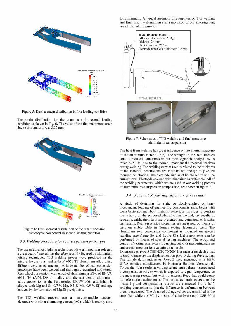
Figure 5: Displacement distribution in first loading condition
The strain distribution for the component in second loading condition is shown in Fig. 6. The value of the first maximum strain due to this analysis was 3,07 mm.
Figure 6: Displacement distribution of the rear suspension
motorcycle component in second loading condition 3.3. Welding procedure for rear suspension prototypes The use of advanced joining techniques plays an important role and a great deal of interest has therefore recently focused on aluminium joining techniques. TIG welding proces were produced in the middle die-cast part and ENAW 6061-T6 aluminium alloy using different welding parameters. A large number of rear suspension prototypes have been welded and thoroughly examined and tested. Rear wheel suspension with extruded aluminium profiles of ENAW 6061- T6 (AlMg1SiCu) - alloy and die-cast central aluminium parts, creates for us the best results. ENAW 6061 aluminium is alloyed with Mg and Si (0.7 % Mg, 0.5 % Mn, 0.9 % Si) and age hardens by the formation of Mg2Si precipitates. The TIG welding process uses a non-consumable tungsten electrode with either alternating current (AC), which is mainly used
for aluminium. A typical assembly of equipment of TIG welding and final result – aluminium rear suspension of our investigation, are illustrated in figure 7. Welding parameters: Filler metal selection: AlMg5:
thickness 2.4 mm Electric current: 235 A Electrode type CeO2: thickness 3.2 mm
FINAL RESULT: ALUMINIUM SWING ARM PROTOTYPE
Figure 7: Schematics of TIG welding and final prototype – aluminium rear suspension
The heat from welding has great influence on the internal structure of the aluminium material [5,6]. The strength in the heat affected zone is reduced, sometimes in our metallographic analysis by as much as 50 %, due to the thermal treatment the material receives during welding. The welding current used is related to the thickness of the material, because the arc must be hot enough to give the required penetration. The electrode size must be chosen to suit the current level. Electrode covered with zirconium is preferable. All of the welding parameters, which we are used in our welding process of aluminium rear suspension composition, are shown in figure 7.
3.4. Static test of rear suspension and final results A study of designing for static or slowly-applied or time-independent loading of engineering components must begin with some basic notions about material behaviour. In order to confirm the validity of the proposed identification method, the results of several identification tests are presented and compared with static test results. Rear suspension properties are measured by means of tests on stable table in Tomos testing laboratory tests. The aluminium rear suspension component is mounted on special standing (see figure 8A and figure 8B). Laboratory tests can be performed by means of special testing machines. The set-up and control of testing parameters is carrying out with measuring sensors and special program for evaluating the results. Extensometer type SCHENCK 70/20N is a measuring device that is used to measure the displacement on pivot 3 during force acting. The sample deformations on Pivot 2 were measured with HBM U1VZ rosettes manufactured by Hottinger Baldwin Messtechnik. To get the right results at varying temperatures these rosettes need a compensation rosette which is exposed to equal temperature as the measuring rosette, but with no external force that could cause its deformation acting on it. The resistance strain gauges on the measuring and compensation rosettes are connected into a half-bridging connection so that the difference in deformation between them is measured. The obtained voltage values are amplified in the amplifier, while the PC, by means of a hardware card USB 9016
15

and software program LabVIEW 7.1, processes them and shows them as deformation as a function of the testing force.
Figure 8:
A) Measuring system for generation of exactly defined loading condition;
B) Dimension of the rear suspension component and the force acting during static testing
The deformations measured were then transferred via a serial interface to a PC and a program LabVIEW 7.1 for data processing and display of results. The deformation measured at different point’s permit four displays in diagram of force as a function of displacement of the aluminium rear suspension prototype (see Figure 9 and Table 2).
Figure 9: The course of deformation during force acting in different
points of the rear suspension Table 2: The results of elastic and plastic deformation on rear wheel
position – pivot 3
Force Pivot 1 F (N)
Force Pivot 2 F (N)
Elastic deformation Δl (mm)
Plastic deformation Δl (mm)
400 1280 0,75 0 500 1600 0,95 0 700 2250 1,4 0 1000 2250 2,1 0 1500 4815 3,2 0 1600 5130 3,25 0 2000 6420 4,2 0 2500 8025 5 0 2770 8900 6 0,3
Amplifier
Extensiometer SCHENCK 70/20N
HBM U1VZ rosettes
Two Pneumatic cylinder Festo 60 -10
The data on force F2 = 1600 N in the table show that deformation in pivot 3 (force acting) reach 3,25 mm.
4. Conclusions A Nowadays, aluminium alloys are used in many applications in which the combination of high strength and low weight is attractive. Automotive industry is one area in which the low weight can be of significant value. This article considers the applications of aluminium within automotive industry and the reasons for the advancement of aluminium. The example of the motorcycle rear suspension reconstruction presented in this article is just one way to analysis the future use and development trends for the joining and assembly of automotive aluminium structures. I have attempted to provide information which I hope will assist with an understanding of the differences and concerns when welding aluminium compared with other materials. The ability successfully to weld aluminium is not so much difficult as it is different. In my view, an understanding of the differences is the first step towards producing successful welding procedure of aluminium and aluminium alloys.
Acting force F
Fixed restraint in z - axis
Rotating restraint in x - axis B
0
500
1000
1500
2000
2500
3000
3500
4000
4500
5000
5500
6000
6500
7000
7500
8000
8500
9000
9500
10000
-1 -0,5 0 0,5 1 1,5 2 2,5 3 3,5 4 4,5 5 5,5 6 6,5 7 7,5 8
Dedorm.ušesa nihajke Deform.osi vpetja Deform. Na koncu nih. Deform. Nihajke-1 0 1 2 3 4 5 6 7 8 mm
Deformation Δ l
10000
9000
8000
7000
6000
5000
4000
3000
2000
1000
Forc
e F
(N) o
n pi
vot 2
Deformation on Pivot 1 Deformation on Pivot 2 Deformation on Pivot 3 Deformation on the end of the rear suspension
The use of aluminium continues to grow within the welding fabrication industry in terms of both size and complexity and with it the need for aluminium filler alloys which will meet these needs, the advancement of welding equipment specifically designed for welding aluminium and the need for resources which can provide industry with technical support. This article considers the applications of aluminium within automotive industry and the reasons for the advancement of aluminium. The work describes a development of rear suspension from idea to the 3D model, making and testing the prototype. It was made a 3D model in a program CATIA V5 R14. This paper presents details of FEM analysis and experimental analysis of motorcycle component behaviour in different loading condition. Careful FEM analyses were carried out in order to understand the effects of different loading condition. Results show that the proposed FEM method of identification in the range of required loading (up to 1600 N) predicts deformation values which are in agreement with those given by static measurements:
The displacement values obtained from the FEM analysis for the first loading condition F1 = 500 N reach 0,939 mm – results from static test reach 0,94 mm;
The displacement values obtained from the FEM analysis for the second loading condition F2 = 1600 N reach 3,07 mm – results from static test reach 3,25 mm.
Due to customer requests for improved properties in areas such as safety, reliability, driving performance, and so on, new material has successively been introduced into motorcycle body to meet these demands.
5. References [1] Waters, D. Operations management, Addison-Wesley Publishing Company, Harlow, 1996
16

[2] Gaither, N. Production and operations management, Wadsworth Publishing Company, 1996 [3] Hollins, B., Pugh, S. Successful product design, Butterworth, 1990 [4] Leijun, L. Failure analysis of aluminium alloy swing arm welded joints, Journal of Failure Analysis and Prevention, 2004, vol. 4, no.3, p. 52-57 [5] Mathers, G. The aluminium and its alloys, Woodhead Publishing Limited, Cambridge England, 2002 [6] Grum, J., Božič, S., Šturm, R. Surface integrity in laser remelting of aluminium alloys, Proceedings from Materials Solutions Conference on Aluminum Casting Technology, Rosemont, Illinois, 1998, p. 277-285.
17