Strength Of Materials/Mechanics of Solids - … Of Materials/Mechanics of Solids Page 3 of 54 ©...
54
Strength Of Materials/Mechanics of Solids Page 1 of 54 © Einstein College of Engineering Department of Civil Engineering Table of Contents Stress, Strain, and Energy 1. Stress and Strain 2. Change in length 3. Determinate Structure - Both ends free 4. Indeterminate Structure - Both ends fixed 5. Composite Material of equal length 6. Composite Material of unequal length 7. Bolt and Nut 8. Thermal Stresses 9. Volumetric Strain 10. Three Modulii 11. Strain Energy Shear force, Bending Moment, Bending stress, and shear stress in beams 1. Shear Force and Bending Moment diagram of beams Cantilever beam Simply supported beam Over hanging beam 2. Bending stress in beams 3. Shear stress in beams Torsion 1. Torsion in shaft Simple Shaft Shaft in series Shaft in parallel Shaft coupled with bolt Shaft coupled with key 2. Torsion in spring Open coil Closed coil Spring in series Spring in parallel Semi elliptical Leaf Spring , Quarter elliptical Leaf Spring Deflection of Beams 1. Slope and Deflection in beams using Macaulay‟s method 2. Slope and Deflection in beams using Moment Area method 3. Slope and Deflection in beams using Conjugate beam method 4. Columns and Struts – Euler‟s Load , Rankine Load , Eccentric load. Thin shells and Principal Stresses 1. Thin cylinder , Thin sphere , and Wound cylinder
-
Upload
duongthien -
Category
Documents
-
view
223 -
download
2
Transcript of Strength Of Materials/Mechanics of Solids - … Of Materials/Mechanics of Solids Page 3 of 54 ©...

Strength Of Materials/Mechanics of Solids
Page 1 of 54 © Einstein College of Engineering
Department of Civil Engineering
Table of Contents
Stress, Strain, and Energy 1. Stress and Strain
2. Change in length
3. Determinate Structure - Both ends free
4. Indeterminate Structure - Both ends fixed
5. Composite Material of equal length
6. Composite Material of unequal length
7. Bolt and Nut
8. Thermal Stresses
9. Volumetric Strain
10. Three Modulii
11. Strain Energy
Shear force, Bending Moment, Bending stress, and shear stress in beams 1. Shear Force and Bending Moment diagram of beams
Cantilever beam
Simply supported beam
Over hanging beam
2. Bending stress in beams
3. Shear stress in beams
Torsion 1. Torsion in shaft
Simple Shaft
Shaft in series
Shaft in parallel
Shaft coupled with bolt
Shaft coupled with key
2. Torsion in spring
Open coil
Closed coil
Spring in series
Spring in parallel
Semi elliptical Leaf Spring, Quarter elliptical Leaf Spring
Deflection of Beams 1. Slope and Deflection in beams using Macaulay‟s method
2. Slope and Deflection in beams using Moment Area method
3. Slope and Deflection in beams using Conjugate beam method
4. Columns and Struts – Euler‟s Load, Rankine Load, Eccentric load.
Thin shells and Principal Stresses 1. Thin cylinder, Thin sphere, and Wound cylinder
Strength Of Materials/Mechanics of Solids
Page 2 of 54 © Einstein College of Engineering
Department of Civil Engineering
2. Principal stresses two dimensions
Truss 1. Method of joint
2. Method of section
3. Graphical method
Short Questions
Exercise
Strength Of Materials/Mechanics of Solids
Page 3 of 54 © Einstein College of Engineering
Department of Civil Engineering
Stress, Strain, and change in length relationship
Stress is proportional to strain within its elastic limit. This law is known as Hooke‟s law.
The material will not return to original shape if the applied stress is more than E.
ζ α ε Stress - ζ Linear Strain – ε
Therefore, ζ = Eε Where E Modulus of Elasticity or Young’s Modulus.
P
ζ = --------- P - Load
A A- Area of the section where the load is applied.
Stresses are three types tensile, compressive, and shear stress. Moment and torsion will
produced any of these stresses.
Strain is nothing but deformation (change in length, breadth, height, diameter, therefore
area or volume) of the body or material due to load. Therefore strain is change in dimension to
the original dimension. It may be length or volume.
δL
ε = --------- δL – Change in length
L L – Original length
Therefore by substituting the value of ζ and ε in the Hook’s law. Change in length
is
PL 4PL
δL = --------- δL = ----------- uniformly varying circular section
AE П Ed1d2
PL
δL = -------------loge(a/b) uniformly varying rectangular section a>b
Et(a-b)
This is the fundamental equation to find change in length of any type of section or step
section using principle of superposition method of varying load, length, area, and material. The
change in length due to compressive load is taken as negative and positive for tensile load.
Types of problem
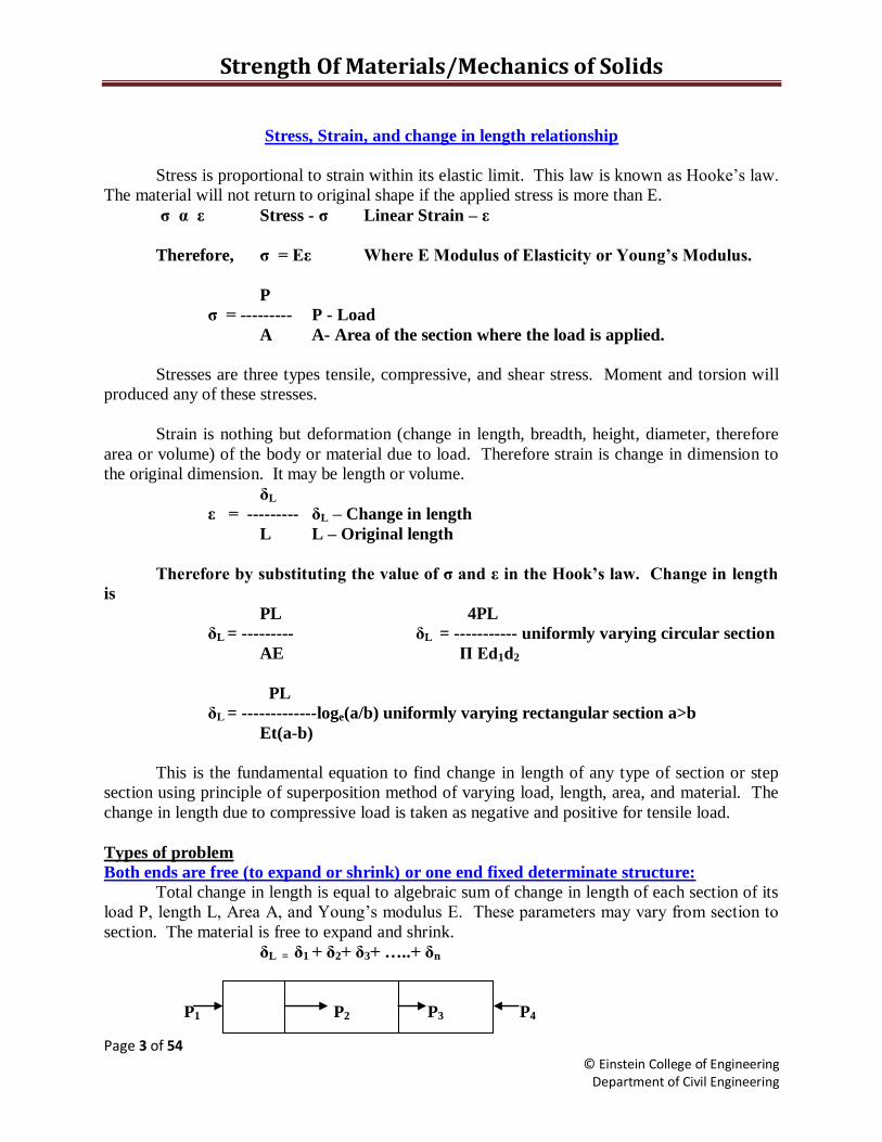
Both ends are free (to expand or shrink) or one end fixed determinate structure:
Total change in length is equal to algebraic sum of change in length of each section of its
load P, length L, Area A, and Young‟s modulus E. These parameters may vary from section to
section. The material is free to expand and shrink.
δL = δ1 + δ2+ δ3+ …..+ δn
P1 P2 P3 P4
Strength Of Materials/Mechanics of Solids
Page 4 of 54 © Einstein College of Engineering
Department of Civil Engineering
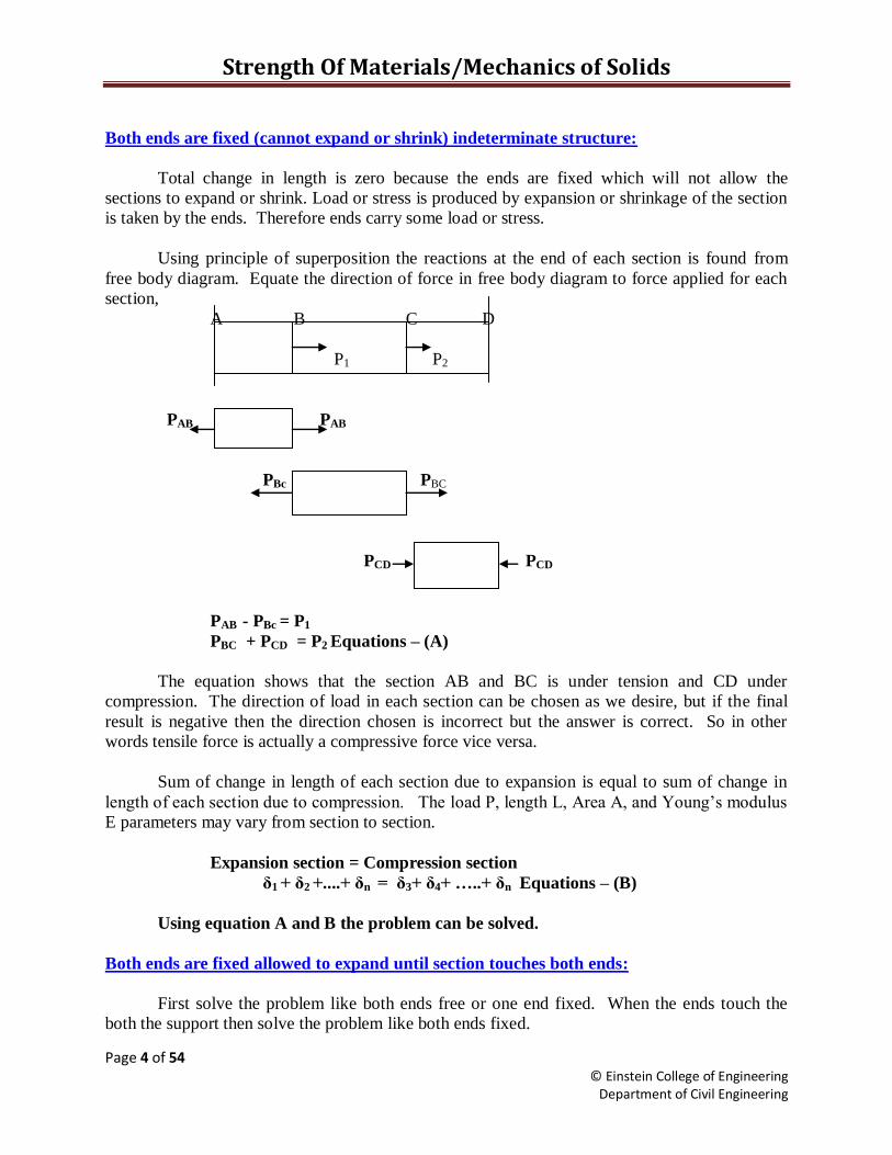
Both ends are fixed (cannot expand or shrink) indeterminate structure:
Total change in length is zero because the ends are fixed which will not allow the
sections to expand or shrink. Load or stress is produced by expansion or shrinkage of the section
is taken by the ends. Therefore ends carry some load or stress.
Using principle of superposition the reactions at the end of each section is found from
free body diagram. Equate the direction of force in free body diagram to force applied for each
section,
A B C D
P1 P2
PAB PAB
PBc PBC
PCD PCD
PAB - PBc = P1
PBC + PCD = P2 Equations – (A)
The equation shows that the section AB and BC is under tension and CD under
compression. The direction of load in each section can be chosen as we desire, but if the final
result is negative then the direction chosen is incorrect but the answer is correct. So in other
words tensile force is actually a compressive force vice versa.
Sum of change in length of each section due to expansion is equal to sum of change in
length of each section due to compression. The load P, length L, Area A, and Young‟s modulus
E parameters may vary from section to section.
Expansion section = Compression section
δ1 + δ2 +....+ δn = δ3+ δ4+ …..+ δn Equations – (B)
Using equation A and B the problem can be solved.
Both ends are fixed allowed to expand until section touches both ends:
First solve the problem like both ends free or one end fixed. When the ends touch the
both the support then solve the problem like both ends fixed.
Strength Of Materials/Mechanics of Solids
Page 5 of 54 © Einstein College of Engineering
Department of Civil Engineering
Composite Material of Equal length and load applied simultaneously at all sections
Reinforced Columns, Supporting load, Suspended load, Composite structure of equal
length (example pipe inside a pipe) these problems can be solved with the following expression.
The change length is same for all materials in that structure. Example in reinforced
concrete column (RCC), steel and concrete length change equally, similarly for supporting load,
suspended load, and composite structure of equal length. Therefore to solve these problems use
the following expressions.
Change in length of concrete = change in length of steel
δlc = δls Equation – (A)
It is same as equation below for equal length only
ζc ζs
------ = --------
Ec Es
For unequal length it is
ζcLc ζsLs
------ = --------
Ec Es
The load P may be shared by two material equally or unequally.
P = Pc + Ps P is Total load, Pc load taken by concrete and Ps steel.
Or P = Ac ζc + As ζs (B)
When the lengths of the composite material are equal by substituting B in A, find the
stresses in the materials.
The ratio of Es/ Ec is known as modular ratio
Composite Material of Unequal length tubular section load applied at different instances
1. Find the material or section whose length is shorter or longer than other material.
1. Calculate the load required to make the section of equal length using formula of δl.
2. This will give the remaining load that will be shared by both the sections.
3. At this point onwards it is similar to composite material of equal length.
Bolt and Nut:
Load in bolt = Load in tube
ζbAb = ζtAt
Change in length is sum of change in length in bolt and change in length in
tube.
δ = δb + δt
Strength Of Materials/Mechanics of Solids
Page 6 of 54 © Einstein College of Engineering
Department of Civil Engineering
Thermal Stresses:
When there is increase in temperature the material expands this will produce stress. This
is known as thermal stress.
δl = L α t
Thermal stresses when the material is not allowed to expand:
δl
ε = ------ = α t ---------Equation (A)
L
ζ = Eε ---------Equation (B)
Substituting A in B
ζ = E α t
Thermal stresses when the material is allowed to expand to a length Δ:
δl = l α t – Δ
δl l α t – Δ
ε = ------ = -------------- Equation (C)
l l
Therefore stress is ζ = Eε.
Thermal Stresses in composite bars:
Therefore load in brass is equal to load in steel because temperature is assumed to
be uniform.
ζsAs = ζbAb - (A)
Change lengths are therefore strains are equal thus,
αbt - ζb αst + ζs
----- = ------ ----------Equation (B)
Eb Es
Substituting equation A in B to find the stresses in the material.
When the thermal coefficient of one material is larger than the other then that material
will be under compression and the other material will be under tension. Thus brass is under
compression and steel is under tension in our example.
Volumetric Strain:
Change in volume to the original volume is known as volumetric strain.

Strength Of Materials/Mechanics of Solids
Page 7 of 54 © Einstein College of Engineering
Department of Civil Engineering
Poisson ratio: It is the ratio of lateral strain to the linear strain. It is denoted by symbol μ
lateral strain 1
μ = ------------------------ or m = ----------
linear strain μ
Change in volume due to axial load in all three directions for a cube or cuboids
δv 1 (ζx + ζy + ζz)(1-2 μ)
------ = ---
V E
This equation is valid only when all the loads are applied as tensile load. The same
equation can be used for the following loads,
1. Compressive load change to minus sign to that direction only for the above formula.
2. Load only in one direction the remaining stresses are zero.
3. Load in two directions the remaining stress is zero.
Change in volume due to axial load for a cylindrical rod
Change in diameter in cylinder is εc = δd /d
Change in length in cylinder is εl = δl /l
Therefore change in volume of cylindrical rod;
δv
------ = εl - 2εc (Minus sign lateral strain are compressive forces) OR
V
δv 1 (ζx)(1-2 μ)
------ = --- Where, ζy and ζz are zero because load in one direction only.
V E
Three important moduli’s are Elasticity, Bulk, and Rigidity
Modulus of Elasticity
ζ PL
E = -------- ε from δl = -----------
ε AE
Bulk Modulus: Ratio of stress over volumetric strain
ζ
K = ----------
(δv/V)
Strength Of Materials/Mechanics of Solids
Page 8 of 54 © Einstein College of Engineering
Department of Civil Engineering
It is also same as when related with E
mE
K = -----------
3(m - 2)
Modulus of Rigidity: Shear stress is proportional to shear strain.
η α θ
η = Cθ
mE
C = -----------
2(m + 1)
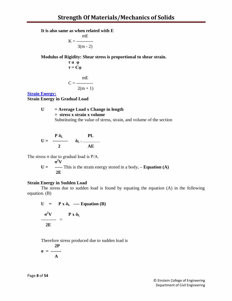
Strain Energy:
Strain Energy in Gradual Load
U = Average Load x Change in length
= stress x strain x volume
Substituting the value of stress, strain, and volume of the section
P δL PL
U = ---------- δL = -----------------
2 AE
The stress ζ due to gradual load is P/A.
ζ2V
U = ----- This is the strain energy stored in a body. – Equation (A)
2E
Strain Energy in Sudden Load
The stress due to sudden load is found by equating the equation (A) in the following
equation. (B)
U = P x δL ---- Equation (B)
ζ2V P x δL
---------- =
2E
Therefore stress produced due to sudden load is
2P
ζ = -------
A

Strength Of Materials/Mechanics of Solids
Page 9 of 54 © Einstein College of Engineering
Department of Civil Engineering
Strain energy due to sudden load is found by substituting the stress ζ due to sudden load
in the following equation
ζ2 V
U = ---------
2E
Strain Energy in Impact Load
U = Load x (height + Change in length)
The stress ζ due to impact load when δL is negligible
√2EPh
ζ = -----------------
AL
The stress ζ due to impact load when δL is not negligible
P 1 + √1+2Eh(PL)
ζ = ------
A
Strain energy due to impact load is found by substituting the stress ζ due to impact load
in the following equation.
ζ2 V
U = ---------
2E
Strength Of Materials/Mechanics of Solids
Page 10 of 54 © Einstein College of Engineering
Department of Civil Engineering
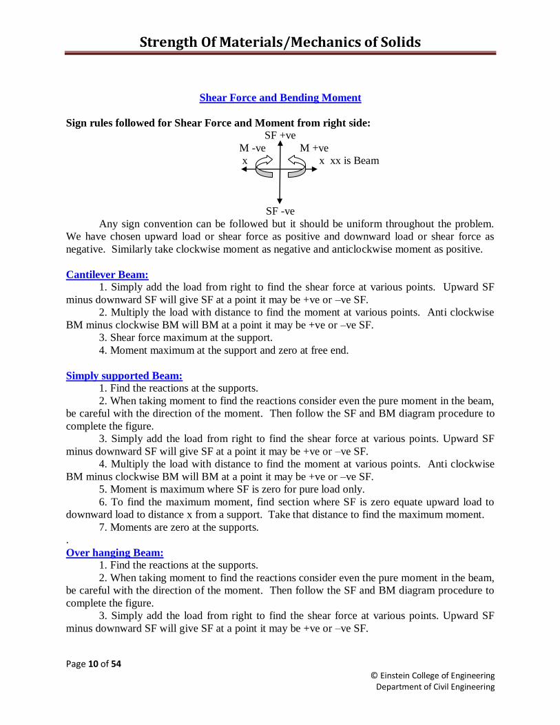
Shear Force and Bending Moment
Sign rules followed for Shear Force and Moment from right side:
SF +ve
M -ve M +ve
x x xx is Beam
SF -ve
Any sign convention can be followed but it should be uniform throughout the problem.
We have chosen upward load or shear force as positive and downward load or shear force as
negative. Similarly take clockwise moment as negative and anticlockwise moment as positive.
Cantilever Beam:
1. Simply add the load from right to find the shear force at various points. Upward SF
minus downward SF will give SF at a point it may be +ve or –ve SF.
2. Multiply the load with distance to find the moment at various points. Anti clockwise
BM minus clockwise BM will BM at a point it may be +ve or –ve SF.
3. Shear force maximum at the support.
4. Moment maximum at the support and zero at free end.
Simply supported Beam:
1. Find the reactions at the supports.
2. When taking moment to find the reactions consider even the pure moment in the beam,
be careful with the direction of the moment. Then follow the SF and BM diagram procedure to
complete the figure.
3. Simply add the load from right to find the shear force at various points. Upward SF
minus downward SF will give SF at a point it may be +ve or –ve SF.
4. Multiply the load with distance to find the moment at various points. Anti clockwise
BM minus clockwise BM will BM at a point it may be +ve or –ve SF.
5. Moment is maximum where SF is zero for pure load only.
6. To find the maximum moment, find section where SF is zero equate upward load to
downward load to distance x from a support. Take that distance to find the maximum moment.
7. Moments are zero at the supports.
.
Over hanging Beam:
1. Find the reactions at the supports.
2. When taking moment to find the reactions consider even the pure moment in the beam,
be careful with the direction of the moment. Then follow the SF and BM diagram procedure to
complete the figure.
3. Simply add the load from right to find the shear force at various points. Upward SF
minus downward SF will give SF at a point it may be +ve or –ve SF.
Strength Of Materials/Mechanics of Solids
Page 11 of 54 © Einstein College of Engineering
Department of Civil Engineering
4. Multiply the load with distance to find the moment at various points. Anti clockwise
BM minus clockwise BM will BM at a point it may be +ve or –ve SF.
5. The moment changes the sign from positive to negative such point is known as point of
contraflexure. To find the point of contraflexure find the section where MB is zero equate
clockwise moments to anti clockwise moment to distance x from a support.
6. Moments are zero at the supports where there is no overhanging, and at the over
hanging end.
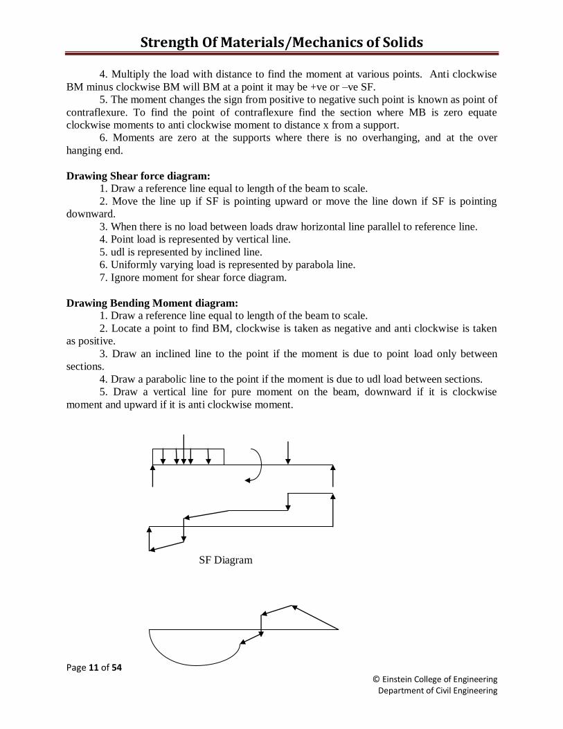
Drawing Shear force diagram:
1. Draw a reference line equal to length of the beam to scale.
2. Move the line up if SF is pointing upward or move the line down if SF is pointing
downward.
3. When there is no load between loads draw horizontal line parallel to reference line.
4. Point load is represented by vertical line.
5. udl is represented by inclined line.
6. Uniformly varying load is represented by parabola line.
7. Ignore moment for shear force diagram.
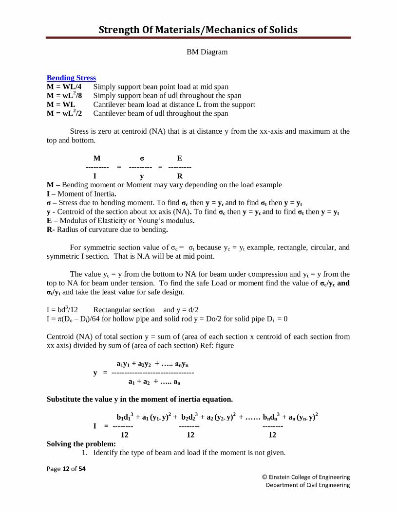
Drawing Bending Moment diagram:
1. Draw a reference line equal to length of the beam to scale.
2. Locate a point to find BM, clockwise is taken as negative and anti clockwise is taken
as positive.
3. Draw an inclined line to the point if the moment is due to point load only between
sections.
4. Draw a parabolic line to the point if the moment is due to udl load between sections.
5. Draw a vertical line for pure moment on the beam, downward if it is clockwise
moment and upward if it is anti clockwise moment.
SF Diagram
Strength Of Materials/Mechanics of Solids
Page 12 of 54 © Einstein College of Engineering
Department of Civil Engineering
BM Diagram
Bending Stress
M = WL/4 Simply support bean point load at mid span
M = wL2/8 Simply support bean of udl throughout the span
M = WL Cantilever beam load at distance L from the support
M = wL2/2 Cantilever beam of udl throughout the span
Stress is zero at centroid (NA) that is at distance y from the xx-axis and maximum at the
top and bottom.
M ζ E
--------- = --------- = ---------
I y R
M – Bending moment or Moment may vary depending on the load example
I – Moment of Inertia.
ζ – Stress due to bending moment. To find ζc then y = yc and to find ζt then y = yt
y - Centroid of the section about xx axis (NA). To find ζc then y = yc and to find ζt then y = yt
E – Modulus of Elasticity or Young‟s modulus.
R- Radius of curvature due to bending.
For symmetric section value of ζc = ζt because yc = yt example, rectangle, circular, and
symmetric I section. That is N.A will be at mid point.
The value yc = y from the bottom to NA for beam under compression and yt = y from the
top to NA for beam under tension. To find the safe Load or moment find the value of ζc/yc and
ζt/yt and take the least value for safe design.
I = bd3/12 Rectangular section and y = d/2
I = π(Do – Di)/64 for hollow pipe and solid rod y = Do/2 for solid pipe Di = 0
Centroid (NA) of total section y = sum of (area of each section x centroid of each section from
xx axis) divided by sum of (area of each section) Ref: figure
a1y1 + a2y2 + ….. anyn
y = --------------------------------
a1 + a2 + ….. an
Substitute the value y in the moment of inertia equation.
b1d13
+ a1 (y1- y)2 + b2d2
3 + a2 (y2- y)
2 + …… bndn
3 + an (yn- y)
2
I = -------- -------- --------
12 12 12
Solving the problem:
1. Identify the type of beam and load if the moment is not given.
Strength Of Materials/Mechanics of Solids
Page 13 of 54 © Einstein College of Engineering
Department of Civil Engineering
2. Find the moment for step 1.
3. Find the Inertia and find the stress.
4. Check the result, at equilibrium ζc / yc = ζt / yt
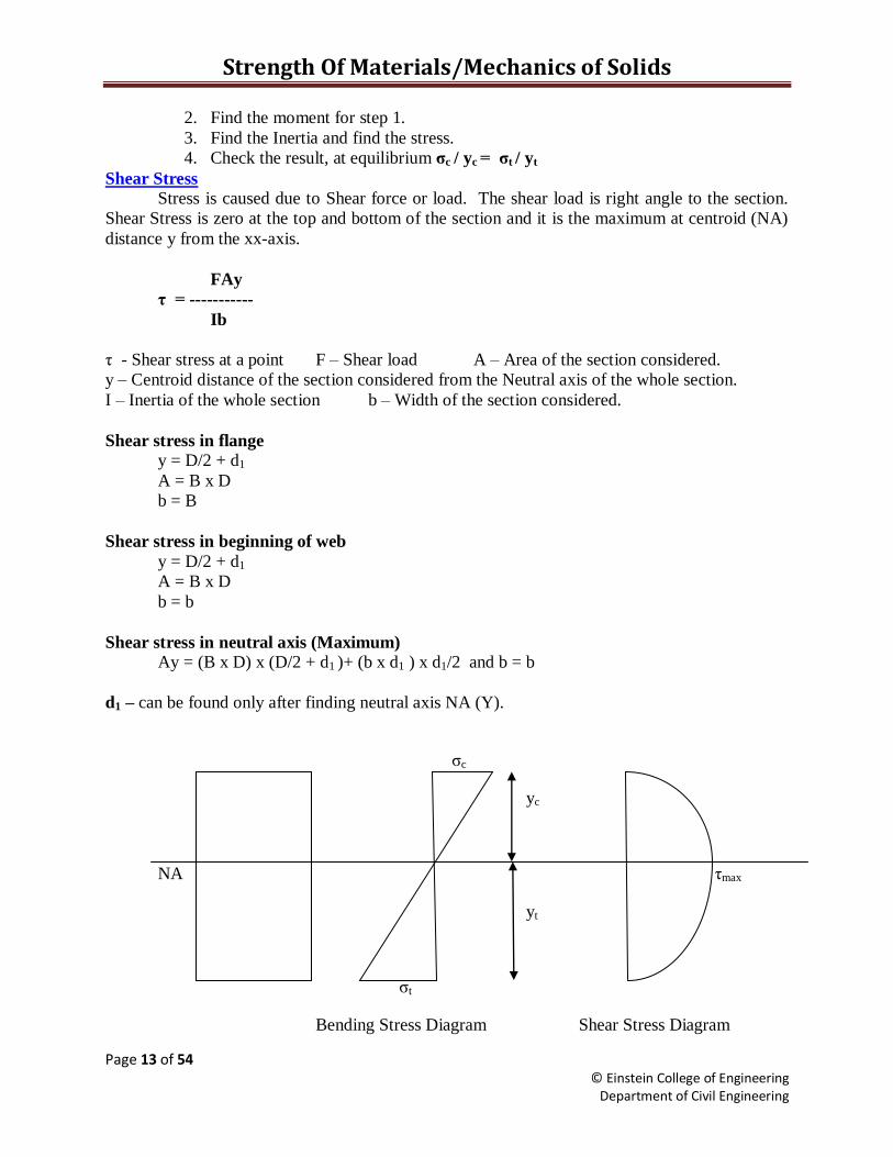
Shear Stress
Stress is caused due to Shear force or load. The shear load is right angle to the section.
Shear Stress is zero at the top and bottom of the section and it is the maximum at centroid (NA)
distance y from the xx-axis.
FAy
η = -----------
Ib
η - Shear stress at a point F – Shear load A – Area of the section considered.
y – Centroid distance of the section considered from the Neutral axis of the whole section.
I – Inertia of the whole section b – Width of the section considered.
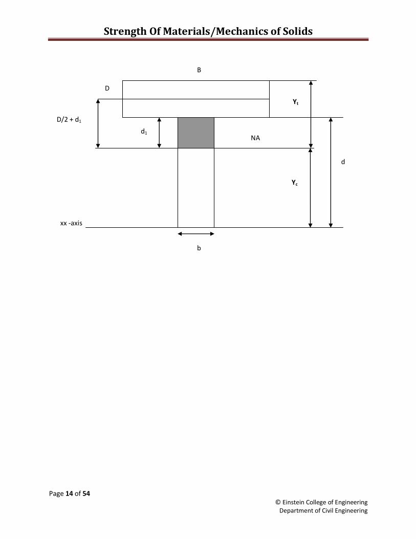
Shear stress in flange
y = D/2 + d1
A = B x D
b = B
Shear stress in beginning of web
y = D/2 + d1
A = B x D
b = b
Shear stress in neutral axis (Maximum)
Ay = (B x D) x (D/2 + d1 )+ (b x d1 ) x d1/2 and b = b
d1 – can be found only after finding neutral axis NA (Y).
ζc
yc
NA ηmax
yt
ζt
Bending Stress Diagram Shear Stress Diagram
Strength Of Materials/Mechanics of Solids
Page 14 of 54 © Einstein College of Engineering
Department of Civil Engineering
Yc
xx -axis
B
D
b
d
d1
D/2 + d1
NA
Yt
Strength Of Materials/Mechanics of Solids
Page 15 of 54 © Einstein College of Engineering
Department of Civil Engineering
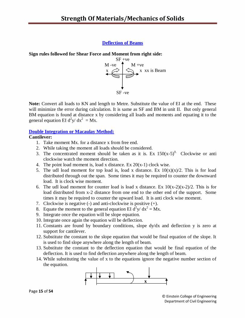
Deflection of Beams
Sign rules followed for Shear Force and Moment from right side:
SF +ve
M -ve M +ve
x x xx is Beam
SF -ve
Note: Convert all loads to KN and length to Metre. Substitute the value of EI at the end. These
will minimize the error during calculation. It is same as SF and BM in unit II. But only general
BM equation is found at distance x by considering all loads and moments and equating it to the
general equation EI d2y/ dx
2 = Mx.
Double Integration or Macaulay Method:
Cantilever:
1. Take moment Mx. for a distance x from free end.
2. While taking the moment all loads should be considered.
3. The concentrated moment should be taken as it is. Ex 150(x-5)0.
Clockwise or anti
clockwise watch the moment direction.
4. The point load moment is, load x distance. Ex 20(x-1) clock wise.
5. The udl load moment for top load is, load x distance. Ex 10(x)(x)/2. This is for load
distributed through out the span. Some times it may be required to counter the downward
load. It is clock wise moment.
6. The udl load moment for counter load is load x distance. Ex 10(x-2)(x-2)/2. This is for
load distributed from x-2 distance from one end to the other end of the support. Some
times it may be required to counter the upward load. It is anti clock wise moment.
7. Clockwise is negative (-) and anti-clockwise is positive (+).
8. Equate the moment to the general equation EI d2y/ dx
2 = Mx.
9. Integrate once the equation will be slope equation.
10. Integrate once again the equation will be deflection.
11. Constants are found by boundary conditions, slope dy/dx and deflection y is zero at
support for cantilever.
12. Substitute the constant to the slope equation that would be final equation of the slope. It
is used to find slope anywhere along the length of beam.
13. Substitute the constant to the deflection equation that would be final equation of the
deflection. It is used to find deflection anywhere along the length of beam.
14. While substituting the value of x to the equations ignore the negative number section of
the equation.
x
Strength Of Materials/Mechanics of Solids
Page 16 of 54 © Einstein College of Engineering
Department of Civil Engineering
Simply Supported Beam or Overhanging beam:
1. Find reaction at the support
2. Take moment Mx. for a distance x from any right support.
3. The concentrated moment should be taken as it is. Ex 150(x-5)0.
Clockwise or anti
clockwise watch the moment direction.
4. The point load moment is, load x distance. Ex 20(x-1) clock wise.
5. The udl load moment for top load is, load x distance. Ex 10(x)(x)/2. This is for load
distributed through out the span. Some times it may be required to counter the downward
load. It is clock wise moment.
6. The udl load moment for counter load is load x distance. Ex 10(x-2)(x-2)/2. This is for
load distributed from x-2 distance from one support to the other end of the support.
Some times it may be required to counter the upward load. It is anti clock wise moment.
7. Clockwise is negative (-) and anti-clockwise is positive(+).
8. Equate the moment to the general equation EI d2y/ dx
2 = Mx.
9. Integrate once the equation will be slope equation.
10. Integrate once again the equation will be deflection.
11. Constants are found by boundary conditions deflection y is zero at supports.
12. Substitute the constant to the slope equation that would be final equation of the slope. It
is used to find slope anywhere along the length of beam.
13. Substitute the constant to the deflection equation that would be final equation of the
deflection. It is used to find deflection anywhere along the length of beam.
14. While substituting value of x to the equations ignore the negative number section of the
equation.
Moment Area method Cantilever:
1. Draw Bending moment Diagram.
2. The total area of the BM diagram will give the slope at free end.
3. To find the slope at the other point in the beam. Find the area of the BM diagram from
the support to that point, that area would give the slope at that point. A/EI
4. The total area of the BM diagram multiplied by centroid from free end will give the
deflection at the free end. Ax/EI x is centroid from point of deflection to be found.
5. To find the deflection at the other point in the beam. Find the area of the BM diagram
from the support to that point multiplied by centroid from that point. That would give the
deflection at that point.
Simply Supported Beam Point load at mid point and/or udl through out the span:
1. Find reaction at the supports.
2. Draw Bending moment Diagram.
3. The total area of the BM diagram divide by two will give the slope at each support.
4. To find the slope at the any point in the beam. Slope at a support minus area of the BM
diagram from the support to that point, that area would give the slope at that point. Slope
= Area of BM/EI.

Strength Of Materials/Mechanics of Solids
Page 17 of 54 © Einstein College of Engineering
Department of Civil Engineering
5. To find the deflection at any point in the beam. Find the area of the BM diagram from the
support to that point multiplied by centroid from that point. That would give the
deflection at that point.
Conjugate method Cantilever:
It is a modification of Moment Area Method. It is effective where the inertia of section is
different along the length of the beam. Conjugate method for cantilever is almost same as
moment area method of cantilever.
1. Draw Bending moment Diagram of the given load.
2. The total area of the BM diagram will give the slope at free end.
3. The sum of the area of the BM diagram at varying inertia from a point to the support
would give the slope at that point. ΣAn/EI
4. The sum of moment of the BM diagram at varying section taken from a point to the
support would give the deflection at that point. ΣAnXn/EI
5. To find the deflection at the other point in the beam. Find the area of the BM diagram
from the support to that point multiplied by centroid from that point. That would give the
deflection at that point.
Conjugate method simply supported beam:
1. Find the reaction of the given load and draw Bending moment Diagram.
2. Find the reaction of the support assuming the bending moment diagram as the load for
varying inertia. This beam is known as conjugate beam.
3. The reaction at the supports will give the slope at the supports.
4. The upward load minus downward load of the conjugate beam will give slope at a point.
5. The moment taken at a point from the conjugate beam will give the deflection.
Columns and Struts
Euler‟s formula is derived for long columns and considered only crippling stress and
ignored direct stress.
Assumptions
1. Column is straight.
2. Load is truly axial.
3. Self weight of column is neglected.
4. Column material is homogenous.
5. Column fails only due to bucking.
6. EI is uniform.
Π2 EI
PE = -------
le2
E – Young‟s modulus
I – Least Moment of Inertia Ixx or Iyy
le – Equivalent length
The product of EI is known as flexural rigidity.
PE
Strength Of Materials/Mechanics of Solids
Page 18 of 54 © Einstein College of Engineering
Department of Civil Engineering
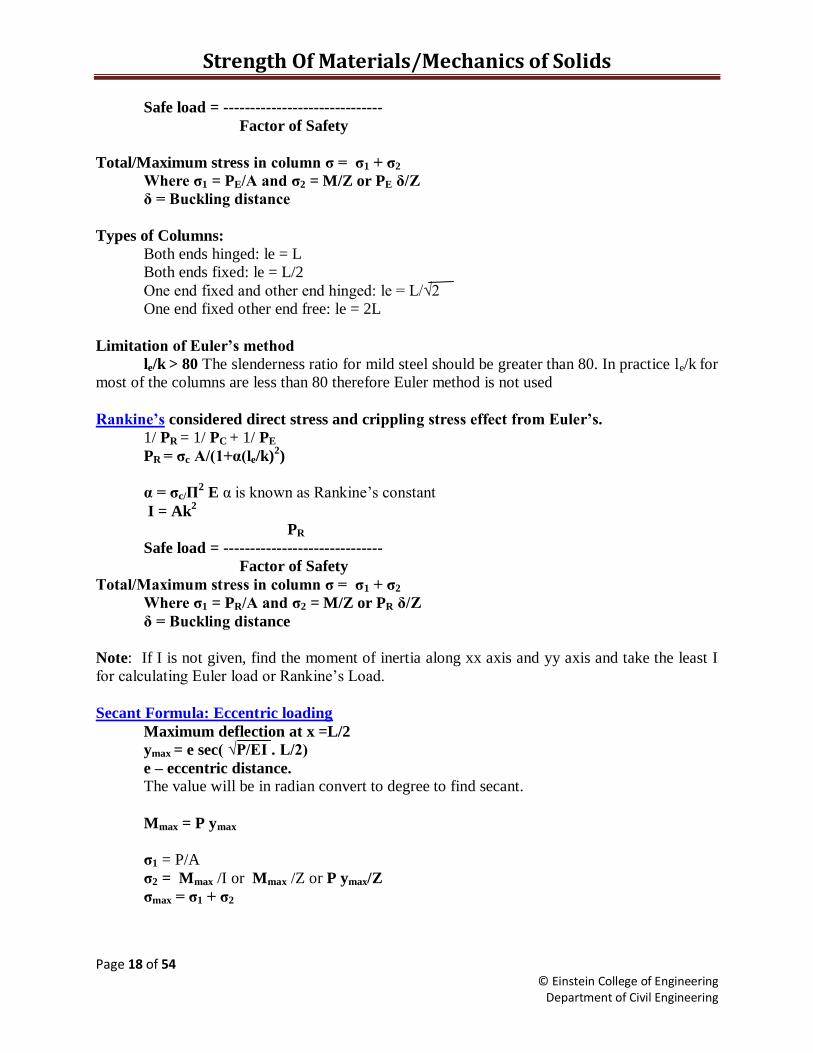
Safe load = ------------------------------
Factor of Safety
Total/Maximum stress in column ζ = ζ1 + ζ2
Where ζ1 = PE/A and ζ2 = M/Z or PE δ/Z
δ = Buckling distance
Types of Columns:
Both ends hinged: le = L
Both ends fixed: le = L/2
One end fixed and other end hinged: le = L/√2
One end fixed other end free: le = 2L
Limitation of Euler’s method
le/k > 80 The slenderness ratio for mild steel should be greater than 80. In practice le/k
for
most of the columns are less than 80 therefore Euler method is not used
Rankine’s considered direct stress and crippling stress effect from Euler’s.
1/ PR = 1/ PC + 1/ PE
PR = ζc A/(1+α(le/k)2)
α = ζc/Π2 E α is known as Rankine‟s constant
I = Ak2
PR
Safe load = ------------------------------
Factor of Safety
Total/Maximum stress in column ζ = ζ1 + ζ2
Where ζ1 = PR/A and ζ2 = M/Z or PR δ/Z
δ = Buckling distance
Note: If I is not given, find the moment of inertia along xx axis and yy axis and take the least I
for calculating Euler load or Rankine‟s Load.
Secant Formula: Eccentric loading
Maximum deflection at x =L/2
ymax = e sec( √P/EI . L/2)
e – eccentric distance.
The value will be in radian convert to degree to find secant.
Mmax = P ymax
ζ1 = P/A
ζ2 = Mmax /I or Mmax /Z or P ymax/Z
ζmax = ζ1 + ζ2
Strength Of Materials/Mechanics of Solids
Page 19 of 54 © Einstein College of Engineering
Department of Civil Engineering
If ζ1 > ζ2 the column is under compression, otherwise it is under tension. To find the
eccentric distance to cause tension substitute ζ2 = ζ1 in ζ2 = P ymax/Z to find the value of ymax and
substitute ymax in ymax = e sec( √P/EI) L/2 to find e.
Strength Of Materials/Mechanics of Solids
Page 20 of 54 © Einstein College of Engineering
Department of Civil Engineering
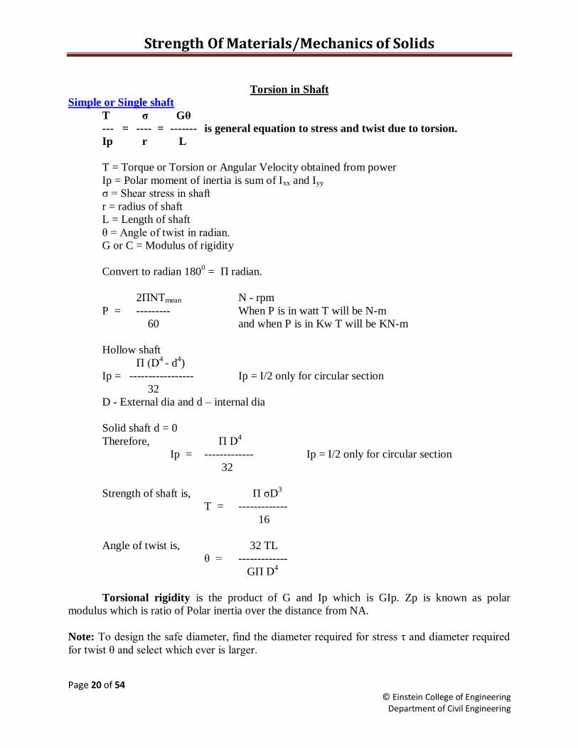
Torsion in Shaft
Simple or Single shaft
T ζ Gθ
--- = ---- = ------- is general equation to stress and twist due to torsion.
Ip r L
T = Torque or Torsion or Angular Velocity obtained from power
Ip = Polar moment of inertia is sum of Ixx and Iyy
ζ = Shear stress in shaft
r = radius of shaft
L = Length of shaft
θ = Angle of twist in radian.
G or C = Modulus of rigidity
Convert to radian 1800 = П radian.
2ПNTmean N - rpm
P = --------- When P is in watt T will be N-m
60 and when P is in Kw T will be KN-m
Hollow shaft
П (D4 - d
4)
Ip = ----------------- Ip = I/2 only for circular section
32
D - External dia and d – internal dia
Solid shaft d = 0
Therefore, П D4
Ip = ------------- Ip = I/2 only for circular section
32
Strength of shaft is, П ζD3
T = -------------
16
Angle of twist is, 32 TL
θ = -------------
GП D4
Torsional rigidity is the product of G and Ip which is GIp. Zp is known as polar
modulus which is ratio of Polar inertia over the distance from NA.
Note: To design the safe diameter, find the diameter required for stress η and diameter required
for twist θ and select which ever is larger.

Strength Of Materials/Mechanics of Solids
Page 21 of 54 © Einstein College of Engineering
Department of Civil Engineering
Shafts in series:
Conditions: Torque is same in shafts T1 = T2
Twist θ = θ1 + θ2 Shafts rotate in same direction
Twist θ = θ1 - θ2 Shafts rotate in opposite direction
Choose the least Torque between shafts for safe stress and angle of twist.
Shafts in parallel:
Conditions: Total Torque T = T1 + T2
Twist is same in both shaft θ1 = θ2
The shafts may be of same material or different material, which is known as composite
shaft.
Strain energy or Torsional resilience in shaft:
It is the amount of energy stored when the shaft is in twisted position.
Torsional energy U = Average Torque x angle of twist
T x θ
U = ------------ --------(A)
2
ζL
θ = ---- substitute θ equation in (A)
Gr
and
ζIp
T = ---- substitute T equation in (A)
r
Therefore, ζ2V
U = ------------
4G
When U is divided by the volume of the shaft, is known as strain energy per unit volume.
Shaft coupled:
The shaft is joined together when the length is not sufficient this is known as coupling of
shaft. It is done in two methods.
1. Using bolts
2. Using key
Bolt method
T can be obtained from shaft expression for bolt and keyed shaft.
ζIp 2πNT
T = ------ or from Power expression P = ----------------
r 60
T is torque in shaft which is transmitted to the coupled shaft through bolts or key.
Therefore torque in bolts or key is equal to torque in shaft.
T = no. of bolts x area of bolt x stress in bolt x radius of bolt circle
Strength Of Materials/Mechanics of Solids
Page 22 of 54 © Einstein College of Engineering
Department of Civil Engineering
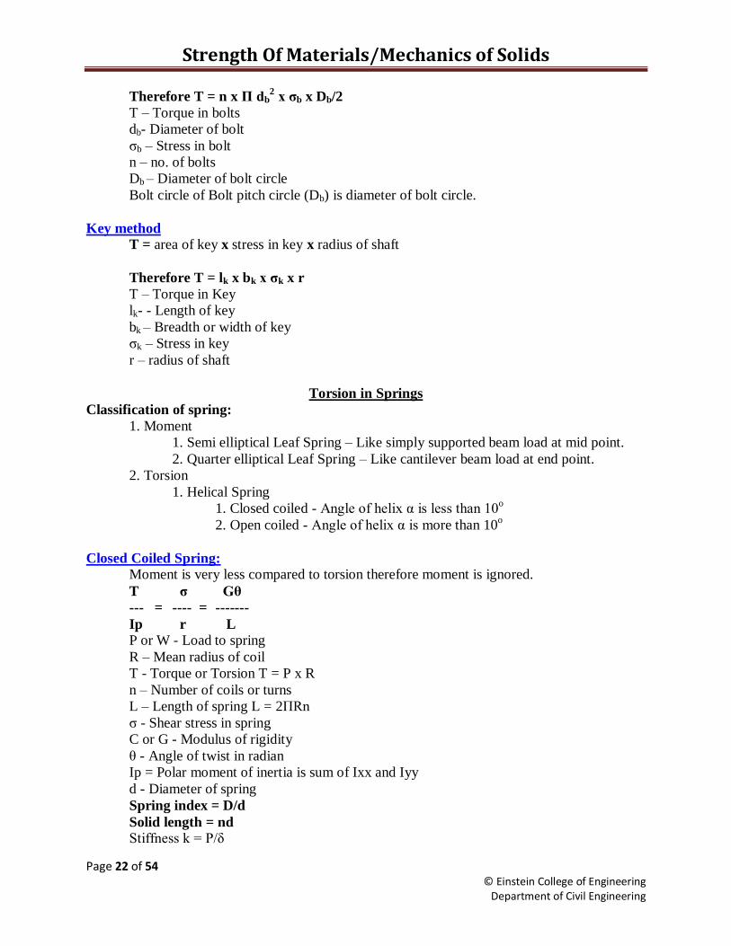
Therefore T = n x П db2 x ζb x Db/2
T – Torque in bolts
db- Diameter of bolt
ζb – Stress in bolt
n – no. of bolts
Db – Diameter of bolt circle
Bolt circle of Bolt pitch circle (Db) is diameter of bolt circle.
Key method
T = area of key x stress in key x radius of shaft
Therefore T = lk x bk x ζk x r
T – Torque in Key
lk- - Length of key
bk – Breadth or width of key
ζk – Stress in key
r – radius of shaft
Torsion in Springs
Classification of spring:
1. Moment
1. Semi elliptical Leaf Spring – Like simply supported beam load at mid point.
2. Quarter elliptical Leaf Spring – Like cantilever beam load at end point.
2. Torsion
1. Helical Spring
1. Closed coiled - Angle of helix α is less than 10o
2. Open coiled - Angle of helix α is more than 10o
Closed Coiled Spring:
Moment is very less compared to torsion therefore moment is ignored.
T ζ Gθ
--- = ---- = -------
Ip r L
P or W - Load to spring
R – Mean radius of coil
T - Torque or Torsion T = P x R
n – Number of coils or turns
L – Length of spring L = 2ПRn
ζ - Shear stress in spring
C or G - Modulus of rigidity
θ - Angle of twist in radian
Ip = Polar moment of inertia is sum of Ixx and Iyy
d - Diameter of spring
Spring index = D/d
Solid length = nd
Stiffness k = P/δ
Strength Of Materials/Mechanics of Solids
Page 23 of 54 © Einstein College of Engineering
Department of Civil Engineering
Deflection δ = Rθ
Пd4 Tr TL
Ip = -------- and ζ = ----------- and θ = ------------
32 Ip G Ip
Therefore,
16PR 64PR3n
ζ = ----------- δ = ------------------
πd3 d
4G
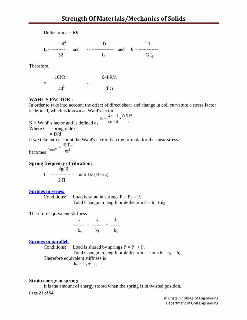
WAHL'S FACTOR : In order to take into account the effect of direct shear and change in coil curvature a stress factor
is defined, which is known as Wahl's factor
K = Wahl' s factor and is defined as
Where C = spring index
= D/d
if we take into account the Wahl's factor than the formula for the shear stress
becomes
Spring frequency of vibration:
√g/ δ
f = ---------------- unit Hz (Hertz)
2 П
Springs in series:
Conditions: Load is same in springs P = P1 = P2
Total Change in length or deflection δ = δ1 + δ2
Therefore equivalent stiffness is
1 1 1
------- = ------- + ------
ke k1 k2
Springs in parallel:
Conditions: Load is shared by springs P = P1 + P2
Total Change in length or deflection is same δ = δ1 = δ2
Therefore equivalent stiffness is
ke = k1 + k2
Strain energy in spring:
It is the amount of energy stored when the spring is in twisted position.
Strength Of Materials/Mechanics of Solids
Page 24 of 54 © Einstein College of Engineering
Department of Civil Engineering
Strain energy U = Average Torque x angle of twist
T θ Pδ
U = ------------ or -------------
2 2
Therefore ζ 2V
U = ------------
4G
When U is divided by the volume of spring, is known as strain energy per unit volume.
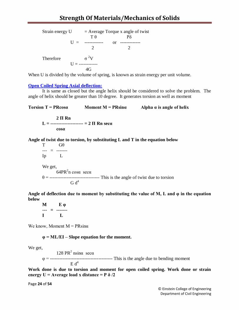
Open Coiled Spring Axial deflection:
It is same as closed but the angle helix should be considered to solve the problem. The
angle of helix should be greater than 10 degree. It generates torsion as well as moment
Torsion T = PRcosα Moment M = PRsinα Alpha α is angle of helix
2 П Rn
L = --------------------- = 2 П Rn secα
cosα
Angle of twist due to torsion, by substituting L and T in the equation below
T Gθ
--- = -------
Ip L
We get,
64PR2n cosα secα
θ = -------------------------------- This is the angle of twist due to torsion
G d4
Angle of deflection due to moment by substituting the value of M, L and θ in the equation
below
M E θ
--- = -------
I L
We know, Moment M = PRsinα
θ = ML/EI – Slope equation for the moment.
We get,
128 PR2 nsinα secα
θ = ---------------------------------------- This is the angle due to bending moment
E d4
Work done is due to torsion and moment for open coiled spring. Work done or strain
energy U = Average load x distance = P δ /2
Strength Of Materials/Mechanics of Solids
Page 25 of 54 © Einstein College of Engineering
Department of Civil Engineering
T θ M θ
U = ----------- + --------------
2 2
P δ T θ M θ
-------- = ----------- + --------------
2 2 2
Substituting the value of θ and θ δ is
64PR3n secα cos
2α 2sin
2α
δ = --------------------------- --------- + ------------
d4 G E
Therefore stress in coil is due to torsion and moment therefore,
16PRcosα 32PRsinα
ζt = --------------- and ζm = ------------------
πd3 πd
3
Total stress in the coil is ζ = ζt + ζm
When, α = 0 it is same as closed coil spring.
Strain energy of open coiled spring is
Pδ
U = -------------
2
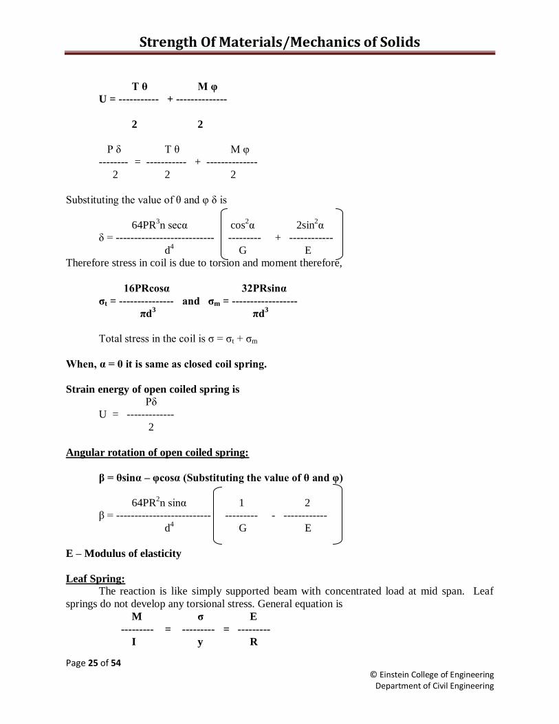
Angular rotation of open coiled spring:
β = θsinα – θcosα (Substituting the value of θ and θ)
64PR2n sinα 1 2
β = -------------------------- --------- - ------------
d4 G E
E – Modulus of elasticity
Leaf Spring:
The reaction is like simply supported beam with concentrated load at mid span. Leaf
springs do not develop any torsional stress. General equation is
M ζ E
--------- = --------- = ---------
I y R
Strength Of Materials/Mechanics of Solids
Page 26 of 54 © Einstein College of Engineering
Department of Civil Engineering
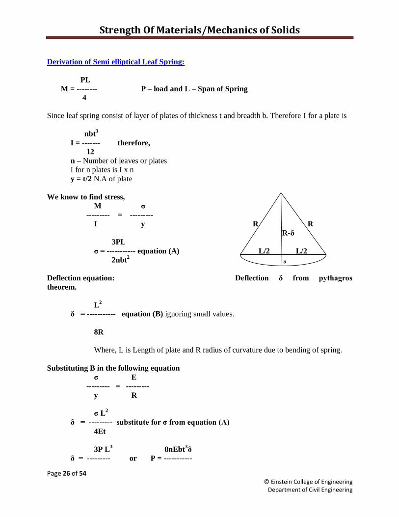
Derivation of Semi elliptical Leaf Spring:
PL
M = -------- P – load and L – Span of Spring
4
Since leaf spring consist of layer of plates of thickness t and breadth b. Therefore I for a plate is
nbt3
I = ------- therefore,
12
n – Number of leaves or plates
I for n plates is I x n
y = t/2 N.A of plate
We know to find stress,
M ζ
--------- = ---------
I y R R
R-δ
3PL
ζ = ----------- equation (A) L/2 L/2
2nbt2 δ
Deflection equation: Deflection δ from pythagros
theorem.
L2
δ = ----------- equation (B) ignoring small values.
8R
Where, L is Length of plate and R radius of curvature due to bending of spring.
Substituting B in the following equation
ζ E
--------- = ---------
y R
ζ L2
δ = --------- substitute for ζ from equation (A)
4Et
3P L3
8nEbt3δ
δ = --------- or P = -----------
Strength Of Materials/Mechanics of Solids
Page 27 of 54 © Einstein College of Engineering
Department of Civil Engineering
8nEbt3 3L
3
Stiffness
P
k = ---------
δ
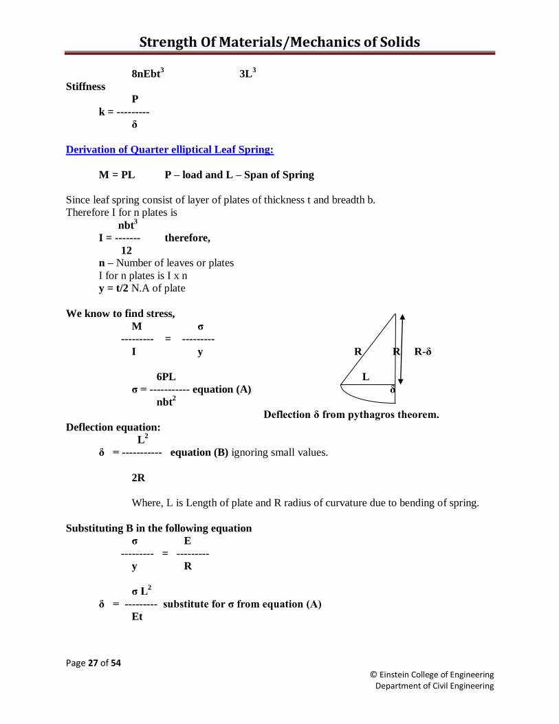
Derivation of Quarter elliptical Leaf Spring:
M = PL P – load and L – Span of Spring
Since leaf spring consist of layer of plates of thickness t and breadth b.
Therefore I for n plates is
nbt3
I = ------- therefore,
12
n – Number of leaves or plates
I for n plates is I x n
y = t/2 N.A of plate
We know to find stress,
M ζ
--------- = ---------
I y R R R-δ
6PL L
ζ = ----------- equation (A) δ
nbt2
Deflection δ from pythagros theorem.
Deflection equation:
L2
δ = ----------- equation (B) ignoring small values.
2R
Where, L is Length of plate and R radius of curvature due to bending of spring.
Substituting B in the following equation
ζ E
--------- = ---------
y R
ζ L2
δ = --------- substitute for ζ from equation (A)
Et

Strength Of Materials/Mechanics of Solids
Page 28 of 54 © Einstein College of Engineering
Department of Civil Engineering
6P L3
nEbt3δ
δ = --------- or P = -----------
nEbt3 6L
3
Stiffness
P
k = ---------
δ
Thin Cylinder
A cylinder whose thickness is 20 times less than the diameter is known as thin cylinder.
When a liquid or gas flows through a pipe it cause stress to the pipe. There are three types of
stresses induced.
Circumferential stress which will cause stress along the length of the cylinder. This will
split the cylinder along the length. This is known as Hoop stress.
Longitudinal stress which will cause stress along the diameter of the cylinder. This will
split the cylinder into two pieces along the diameter.
Radial stress is negligible so it is ignored.
Both the circumferential and longitudinal stresses are tensile. This is an important point
to be remembered to find the change in volume.
Circumferential stress:
Resisting force by cylinder along length of pipe = force due to fluid pressure along length
of pipe. pd
ζc 2tL = pdL Thus ζc= ------------
2t
Longitudinal stress:
Resisting force by cylinder along diameter of pipe = force due to fluid pressure along
diameter of pipe.
ζL П Dt = p (П D2/4) pD
Thus ζL = ----------
4t
Thus Hoop stress is two times greater than longitudinal stress. To find the thickness
Hoop stress should be used.
Some times cylinders will have joints this will reduce the strength at the joint. Therefore
and efficiency of joint (η) is included in the above expressions.
pD pD
ζc = ------------ and ζl = ------------
2tηc 4tηL

Strength Of Materials/Mechanics of Solids
Page 29 of 54 © Einstein College of Engineering
Department of Civil Engineering
p – Pressure due to liquid or gas
D – Diameter of cylinder
t – Thickness of cylinder
L – Length of cylinder
η – Efficiency of joint it may vary due to stress.
From Hooke‟s law strain ε = ζ/E. This is the general equation for strain from which
change in dimension can be found.
Strain due to circumferential stress cause increase in diameter
pD 1
εc = ------ 1 - ----
2tE 2m
(OR)
ζc ζL εc = ------ - -----
E mE
Strain due to longitudinal stress cause increase in length
pD 1 1
εl = ------ ----- - ----
2tE 2 m
(OR)
ζL ζc
εc = ------ - -----
E mE
Change in diameter in cylinder is δd = εc D
Change in length in cylinder is δl = εl L
Therefore change in volume of Cylinder:
δv pD 5 2
------ = εl + 2εc (OR) = -------- --- - -----
V 2tE 2 m

Strength Of Materials/Mechanics of Solids
Page 30 of 54 © Einstein College of Engineering
Department of Civil Engineering
Thin Spherical Shells:
ζ П Dt = p (П D2/4)
pD
Thus ζ = ------------
4t
pd
ζ = ------------ Stress due efficiency in joints
4tη
Strain due to stress
pD 1
ε = ------ 1 - ----
4tE m
(OR)
ζ ζ
ε = ------ - ------
E mE
Therefore change in diameter in cylinder is δd = ε d
Change in volume of Cylinder:
δv
------ = 3ε
V
Thin cylinder wound to a unit Length:
Stress in cylinder due to initial winding = Stress in wire due to initial winding
ζc1 2tL = ζw1 2π dw2 L
-------------- ------ (2 because of two sides n=L/dw)
4 dw
Thus ζc1 = π dw ζw1
----------------
4t
Stress due to internal pressure p = Stress in cylinder + Stress in wire
pDL = ζc2 2tL + ζw2 2π dw2 L
--------- ----
4 dw
Strength Of Materials/Mechanics of Solids
Page 31 of 54 © Einstein College of Engineering
Department of Civil Engineering
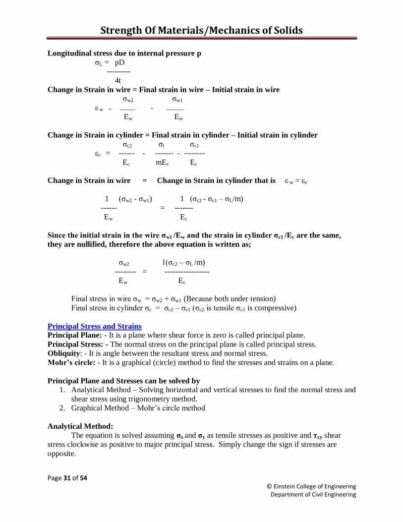
Longitudinal stress due to internal pressure p
ζL = pD
---------
4t
Change in Strain in wire = Final strain in wire – Initial strain in wire
ζw2 ζw1
ε w = --------- - ----------
Ew Ew
Change in Strain in cylinder = Final strain in cylinder – Initial strain in cylinder
ζc2 ζl ζc1
εc = ------ - ------- - --------
Ec mEc Ec
Change in Strain in wire = Change in Strain in cylinder that is ε w = εc
1 (ζw2 - ζw1) 1 (ζc2 - ζc1 – ζL/m)
------ = -------
Ew Ec
Since the initial strain in the wire ζw1 /Ew and the strain in cylinder ζc1 /Ec are the same,
they are nullified, therefore the above equation is written as;
ζw2 1(ζc2 – ζL /m)
-------- = -----------------
Ew Ec
Final stress in wire ζw = ζw2 + ζw1 (Because both under tension)
Final stress in cylinder ζc = ζc2 – ζc1 (ζc2 is tensile ζc1 is compressive)
Principal Stress and Strains
Principal Plane: - It is a plane where shear force is zero is called principal plane.
Principal Stress: - The normal stress on the principal plane is called principal stress.
Obliquity: - It is angle between the resultant stress and normal stress.
Mohr’s circle: - It is a graphical (circle) method to find the stresses and strains on a plane.
Principal Plane and Stresses can be solved by
1. Analytical Method – Solving horizontal and vertical stresses to find the normal stress and
shear stress using trigonometry method.
2. Graphical Method – Mohr‟s circle method
Analytical Method:
The equation is solved assuming ζx and ζy as tensile stresses as positive and ηxy shear
stress clockwise as positive to major principal stress. Simply change the sign if stresses are
opposite.

Strength Of Materials/Mechanics of Solids
Page 32 of 54 © Einstein College of Engineering
Department of Civil Engineering
General equation to find the normal stress:
ζn = ζxSin2θ + ζyCos
2θ- 2ηxySinθCosθ
General equation to find the shear stress:
ζt = ζxSinθCosθ – ζySinθCosθ + ηxySin2θ - ηxyCos
2θ
The resultant stress, ζR2
= ζn2
+ ζt2
Inclination of resultant stress:
ζt
tanθ = ------
ζn
Maximum principal stress
(ζx + ζy) ζx - ζy 2
ζmax = --------------- + ----------- + η2
2 2
Minimum principal stress
(ζx + ζy) ζx - ζy 2
ζmin = --------------- - ---------- + η2
2 2
Maximum shear stress
ζx - ζy 2
η max = ---------- + η2
2
Location of principal Stress:
2η
tan2θp = -------------
ζmax - ζmin
Location of Shear Stress:
ζmax - ζmin
tan2θs = -------------
2η
Graphical Method - Drawing Rules of Mohr’s Circle:
1. Fix the origin (0,0) that is (x,y) at convenient place in the graph.
2. X – axis to locate axial stress for both x and y directions.
3. Y – axis to locate shear stress for clockwise and anti clockwise shear.
4. Tensile stress is positive along x axis right of origin.
Strength Of Materials/Mechanics of Solids
Page 33 of 54 © Einstein College of Engineering
Department of Civil Engineering
5. Compressive stress is negative along x axis left of origin.
6. Clockwise Shear stress is positive along y axis upward of origin.
7. Anti clockwise shear stress is negative along y axis downward of origin..
8. When there is no shear force (ηxy= 0) draw Mohr‟s circle from axial stresses. The centre
of the Mohr‟s circle bisects axial stresses (ζx,0) and (ζy,0).
9. When there is shear force draw Mohr‟s circle from axial stresses and shear stress. The
centre of the Mohr‟s circle bisects the line between (ζx, ηxy) and (ζy, ηxy).
10. Angle of inclination is to be drawn from point (ζy, ηxy) at centre of Mohr‟s to angle 2θ in
clockwise direction.
11. Normal stress, and maximum and minimum principal stresses are taken from the origin
along the x-axis of the Mohr‟s circle.
12. Maximum shear stress is the radius of the Mohr‟s circle, and shear stresses are taken
along the y-axis of the Mohr‟s circle.
13. The angle between the resultant stress and normal stress in angle of oblique.
Strength Of Materials/Mechanics of Solids
Page 34 of 54 © Einstein College of Engineering
Department of Civil Engineering
Strength Of Materials/Mechanics of Solids
Page 35 of 54 © Einstein College of Engineering
Department of Civil Engineering
2θ
C
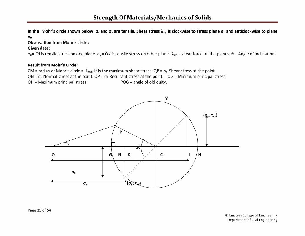
In the Mohr’s circle shown below σx and σy are tensile. Shear stress λxy is clockwise to stress plane σx and anticlockwise to plane σy. Observation from Mohr’s circle: Given data: σx = OJ is tensile stress on one plane. σy = OK is tensile stress on other plane. λxy is shear force on the planes. θ – Angle of inclination. Result from Mohr’s Circle: CM = radius of Mohr’s circle = λmax It is the maximum shear stress. QP = σt Shear stress at the point. ON = σn Normal stress at the point. OP = σR Resultant stress at the point. OG = Minimum principal stress OH = Maximum principal stress. POG = angle of obliquity.
M (σx , τxy) P O G N K C J H
σx
σy (σy , τxy)
Strength of Materials/Mechanics of Solids
Page 36 of 54 © Einstein College of Engineering
Department of Civil Engineering
When frames are connected together to form a structure is called truss. Thus the frame
becomes stable and strengthened to carry more loads. The load may be tensile or compressive.
A truss is said to be perfect frame if it satisfies the following equation n = 2j -3. Where j is
number of joints and n is number of frames. Example when j=3 then n=3, it is a perfect frame.
A frame is said to be imperfect frame when n > 3or n < 3 for j=3. When n>3 then is called
redundant frame and when n<3 it is called deficient frame. The assumption of force is as
follows arrow moving towards the joint is compression and away from the joint is tension. In a
member the arrow should either move towards the joints or away from the joint. It cannot have
arrow differently for member joints. The forces in the truss are analyzed from the following
methods.
1. Method of joints
2. Method of sections
3. Graphical method.
Method of Joints:
1. First find the reaction at the supports.
2. Then chose the joints where there are only two unknowns‟ forces. The forces in the
unknowns truss are found from horizontal forces ΣH = 0 and vertical forces ΣV = 0.
3. An inclined member force will produce a vertical force and horizontal force. Example a
force at point towards the first quadrant will have downward vertical force and leftward
horizontal force.
4. Assume forces in the members as compressive or tensile force. Resolve the forces in the
members.
5. Find forces in the unknown members as done in engineering mechanics using step 2.
6. If the answer is negative then the assumption are incorrect; in such case simply change
the sign.
Method of sections:
1. First find the reaction at the supports.
2. Then cut the section where forces to be determined. It should not cut more than three
members.
3. The forces in the unknowns truss are found from moment equation ΣM = 0 at a joint from
a joint. Take the moment for forces at left or right of the cut section, and forces for the
cut sections frames only. Take the moment only at joints where sections are cut. Moment
is load multiplied by perpendicular distance.
4. Assume forces in the members as compressive or tensile force.
5. Find forces in the unknown members as done in engineering mechanics using step 2.
6. If the resultant force is negative then the assumption are incorrect; in such case simply
change the sign.
7. The advantage of this method is forces of any member can be found using this method.
Graphical Method:
1. First find the reaction at the supports.
Strength of Materials/Mechanics of Solids
Page 37 of 54 © Einstein College of Engineering
Department of Civil Engineering
2. Develop a Bow notation to identify the frame and the forces.
3. Draw the forces to scale at each point and for the reaction forces.
4. Draw the members from the each joint parallel to the direction of the members.
5. The members will intersect at a point the measured distance will be forces in the truss.
Strength of Materials/Mechanics of Solids
Page 38 of 54 © Einstein College of Engineering
Department of Civil Engineering
Strength of Materials for Mechanical Engineering only
Expected Types of Questions in Part B based on Topics
Unit I - Question 11
1. Change in length of determinate or indeterminate structure. Stress in composite structure.
(RCC, Equal length, unequal length, Bolt and Nut)
OR
1. Thermal stress
2. Change in lateral dimension using Poisson‟s ration and three modulli
3. Volumetric strain.
4. Strain Energy.
Unit II - Question 12
Shear force and Bending Moment diagram of beams.
1. Cantilever Beam
2. Simply supported Beam (Shear force zero and Maximum bending moment)
3. Overhanging Beam (Shear force zero and point of contra flexure)
OR
1. Stress caused due to moment M/I = ζ/y = E/R
2. Shear Stress η = Fay/Ib
Unit III - Question 13
1. Torsion in shaft T/Ip= ζ/r = Gθ/L
OR
1. Torsion in Spring T/Ip= ζ/r = Gθ/L
Unit IV - Question 14
1. Deflection of Beam
Double Integration/Macaulay/Moment Area Method
2. Column Load
Euler Load, Rankine Load, and Eccentric Load Column
OR
1. Deflection of Beam
Moment Area Method
2. Column Load
Euler Load, Rankine Load, and Eccentric Load Column
Unit V - Question 15
1. Thin Cylinder or Sphere stresses or wound cylinder.
OR
2. Principal Stress and strain
Strength of Materials/Mechanics of Solids
Page 39 of 54 © Einstein College of Engineering
Department of Civil Engineering
Mechanics of Solids for Civil Engineering only
Expected Types of Questions in Part B based on Topics
Unit I - Question 11
1. Change in length of determinate or indeterminate structure. Stress in composite structure.
(RCC, Equal length, unequal length, Bolt and Nut)
OR
1. Thermal stress
2. Change in lateral dimension using Poisson‟s ration and three modulli
3. Volumetric strain.
4. Principal Stress and Strain.
Unit II - Question 12
1. Truss
OR
2. Truss or Thin Cylinder or Sphere stresses or wound cylinder.
Unit III - Question 13
Shear force and Bending Moment diagram of beams.
1. Cantilever Beam
2. Simply supported Beam (Shear force zero and Maximum bending moment)
3. Overhanging Beam (Shear force zero and point of contra flexure)
OR
1. Stress caused due to moment M/I = ζ/y = E/R
Unit IV - Question 14
1. Deflection of Beam
Macaulay Method, Moment Area Method, and Conjugate Beam Method
OR
2. Conjugate beam or Shear Stress η = Fay/Ib
Unit V - Question 15
1. Torsion in shaft T/Ip= ζ/r = Gθ/L
OR
1. Torsion in Spring T/Ip= ζ/r = Gθ/L
Strength of Materials/Mechanics of Solids
Page 40 of 54 © Einstein College of Engineering
Department of Civil Engineering
Short Questions and Answers
Stress, Strain, Energy& Moduli
1. Define Hooke‟s law.
Hooke‟s law states that stress is proportional to strain within its elastic limit.
2. Define stress.
Stress is load divided by area.
3. Define strain.
Strain is the ratio of change in dimension over original dimension.
4. What are the types of stresses?
1. Axial Stress.
2. Bending stress.
3. Shear stress.
5. What are differ types of strains
1. Linear strain.
2. Lateral strain.
3. Volumetric strain.
4. Shear strain.
6. What is difference between rigid and deformable bodies?
Rigid bodies will take more compressive load than the tensile load (Ex: brick
stone, etc).
Deformable bodies can take both tensile and compressive load (Ex: Steel, copper,
etc).
7. Define volumetric strain.
It is the change in volume over original volume.
8. What is relationship between Young‟s modulus, bulk modulus, and modulus of rigidity?
mE
Bulk Modulus K = -----------
3(m - 2)
mE
Modulus of Rigidity C = -----------
2(m + 1)
9. Define resilience (Or) Strain energy
It is the strain energy stored in the body.
Strength of Materials/Mechanics of Solids
Page 41 of 54 © Einstein College of Engineering
Department of Civil Engineering
10. Define proof resilience.
It is the maximum strain energy stored in the body.
11. Define Modulus of resilience.
It is the ratio of proof resilience over volume of the body.
12. Define Poisson ratio.
It is the ratio of lateral strain over linear strain.
13. Define Thermal stress.
It is stress or load induced due to change in temperature. This causes a material to
expand or shrink.
14. Define Bulk Modulus.
It is the ratio of stress over volumetric strain.
15. What is the effect of change in temperature in the composite bar?
In the composite bar a materiel with lower co-efficient of expansion will be under
tensile stress where as the material with higher co-efficient expansion will be under
compressive stress.
16. Define Uniform strength
A section is said to be of uniform strength when the stress are equal along the
length of the section. The self weight of the material is ignored for easier calculation in
practice if the self weight is considered then the cross section area of the material will be
maximum at the top and minimum at the bottom for the hanging section.
Shear force, Bending Moment, Bending Stress & Shear Stress in beams
1. What are the different types of loads
1. Point load 2.Uniformly distributed load (udl) 3.Uniformly varying load (uvl).
2. What are the different types of beams?
1. Cantilever beam 2.Simply supported beam 3. Fixed Beam 4.Over hanging
beam 5.Contionuous beam.
3. Define Shear force and bending moment.
Shear is total load acting at a point (upward load – downward load). Bending
moment at a point is product of load and distance (anticlockwise moment – clockwise
moment).
4. What are the assumptions in the theory of simple bending?
1. Beam is straight.
2. Each layer expand and contract independently.
3. Load acts normal to the axis of the beam.
4. Beam material is homogeneous.
Strength of Materials/Mechanics of Solids
Page 42 of 54 © Einstein College of Engineering
Department of Civil Engineering
5. Young‟s modulus is same fore tension and compression.
5. Define point of contra flexure.
It is a point where the bending moment changes its sign from +ve to –ve or –ve to
+ve. At that point bending moment is Zero.
6. Define flexural rigidity.
It is the product of moment of inertia and young‟s modulus (EI).
7. Define section modulus.
It is the ratio of moment of inertia over the neutral axis (Z=I/y). It is denoted by
“Z”. It is also known as strength of the section.
8. Where will be the maximum bending moment in simply supported beam?
Bending moment is maximum where shear fore is zero.
9. Where will be the maximum bending stress in the beam?
The bending stress is the maximum at the ends of the section. And Zero at neutral
axis.
10. Where will be the maximum Shear stress in a beam?
The maximum shear stress is the maximum at neutral axis and zero at the ends.
11. Write down the relationship between intensity of loading, S.F and B.M.
Torsion in shaft and spring
1. Define Torsion.
It is the angle of twist due to the load.
2. Define torsional rigidity.
It is a product of modulus of rigidity and polar moment of inertia (GIp).
3. How does the shear stress vary across a solid shaft?
The stress is zero at the centre (neutral axis) and maximum at the perimeter.
4. For same weight, which shaft will carry more torque, a solid one or a hollow one? Why?
Hollow shaft will carry more torque because polar inertia will be more for hollow
shaft to solid shaft for the weight and length.
5. What are the types of spring?
Springs are following types.
1. Semi elliptical Leaf spring.
2. Quarter elliptical Leaf spring.
3. Closed coil helical spring
Strength of Materials/Mechanics of Solids
Page 43 of 54 © Einstein College of Engineering
Department of Civil Engineering
4. Open coil helical spring
6. What are leaf springs?
Several plates are fastened together one over the other to form a layer of plates,
such arrangements are known as leaf springs.
7. What is the difference between closed coil and open coil spring
Closed Coil Open coil
Angle of helix is less than 10o Angle of helix greater than 20
o
It is used for tensile load It is used for both tensile and
compressive load
Eg: Brake, accelerator Eg :Shock absorber, ballpoint pen
8. Define Wahl‟s factor.
The effect of direct shear and change in coil curvature a stress factor is defined,
which is known as Wahl's factor.
K = Wahl‟s factor, if we take into account the Wahl's factor then the formula for the
shear stress becomes
9. What are the conditions to design a circular shaft?
1. The stress should be within the limit of the torque.
2. Angle of twist should be within the torque.
10. Define torsional energy or torsional resilience.
It is the strain energy stored due to angular twist. It is the product of Average
torque and twist.
11. Define stiffness.
It is a ratio of load over change in length.
12. Express the strength of solid shaft
T = πζd3/16
13. How shafts are coupled?
Shafts are coupled by key or bolts.
Deflection of Beams and Load & Buckling of columns.
1. What are the assumptions of double integration method?
Strength of Materials/Mechanics of Solids
Page 44 of 54 © Einstein College of Engineering
Department of Civil Engineering
1. The equation is based on the bending moment.
2. The effect of shear force is very small and thus neglected.
3. Beams are uniform
4. Inertia is uniform.
5. Material is homogenous.
2. Define Mohr theorems or moment area therorems.
Slope Theorem
It is the ratio of area of bending moment diagram over the flexural rigidity is
called Mohr first theorem, to find the slope (A/EI).
Deflection Theorem
It is the product of slope and centroidal distance from a point, to find the
deflection (Ax/EI).
3. What is a conjugate beam?
It is hypothetical beam; the load is derived from the bending moment diagram of
the actual beam to find the slope and deflection. It is useful for varying I section along
the span. The reaction at the support from the BM diagram load will give the slope.
4. What are the assumptions of Euler?
1. Column is straight.
2. Load is axial.
3. Self weight is neglected.
4. Column material is homogeneous.
5. Column fails due to buckling.
6. EI(flexural rigidity) is uniform
5. Define slenderness ratio.
It is the ratio of equal length of column over minimum radius of gyration.
6. What are the different types of ends and their equivalent length in the column?
1. Both ends hinged. (le=L)
2. Both ends fixed. (le=L/2)
3. One end hinged other end fixed. (le=1.414L(root 2*L))
4. One end fixed other end free. (le=2L)
Stress and Strain in Thin cylinder and Sphere
Principal stresses and strains
1. Define Thin Cylinder or Sphere.
A Cylinder whose thickness is 20 times less than its diameter is known as thin
cylinder.
2. What are the different types of stresses in cylinder?
Strength of Materials/Mechanics of Solids
Page 45 of 54 © Einstein College of Engineering
Department of Civil Engineering
1. Circumferential stress of Hoop stress.
2. Longitudinal Stress
3. Radial stress
3. Define Hoop Stress.
Hoop stress is the stress induced by fluid or gas inside the cylinder perpendicular
to the length of the pipe. The thickness of the cylinder is decided based on hoop stress
value because hoop stress is two times more than the longitudinal stress.
4. Define longitudinal stress
Longitudinal stress is the stress induced by the fluid or gas along the length of the
cylinder
5. How to increase the strength of a thin cylinder?
Winding the cylinder using thin wire.
6. Define Mohr‟s Circle.
It is the graphical representation to find stresses on a plane.
7. Define principal plane
It is a plane where shear force is zero is called principal plane.
8. Define Principal Stress.
The normal stress on the principal plane is called principal stress.
9. Define Oblique.
It is the angle between the resultant stress and normal stress.
10. In a Mohr‟s circle of stresses, what represents the maximum shear stress?
The radius of the Mohr‟s circle.
Truss
1. What are the two types of trusses with respect to their joints? 1. Perfect truss and 2. Imperfect truss
2. What are guided supports?
3. When do you adopt method of sections?
To find the forces in required members method of section is simpler.
4. Define tension coefficient
Tension coefficient t for a member is defined as tensile force T in the member
divided by its length L.
Strength of Materials/Mechanics of Solids
Page 46 of 54 © Einstein College of Engineering
Department of Civil Engineering
Exercise
Stress, Strain, Thermal Stress, Modulli
1. The following observations are made during a tensile test on a mild steel specimen 60 mm in
diameter and 210 mm long. Elongation with 40 kN load (within limit of proportionality). l =
0.0304 mm, yield load = 156 kN
Maximum load = 250 kN
Length of specimen at fracture = 235 mm.
Determine:
(i) Young‟s Modulus of Elasticity
(ii) Yield point stress
(iii) Ultimate stress
(iv) Percentage elongation
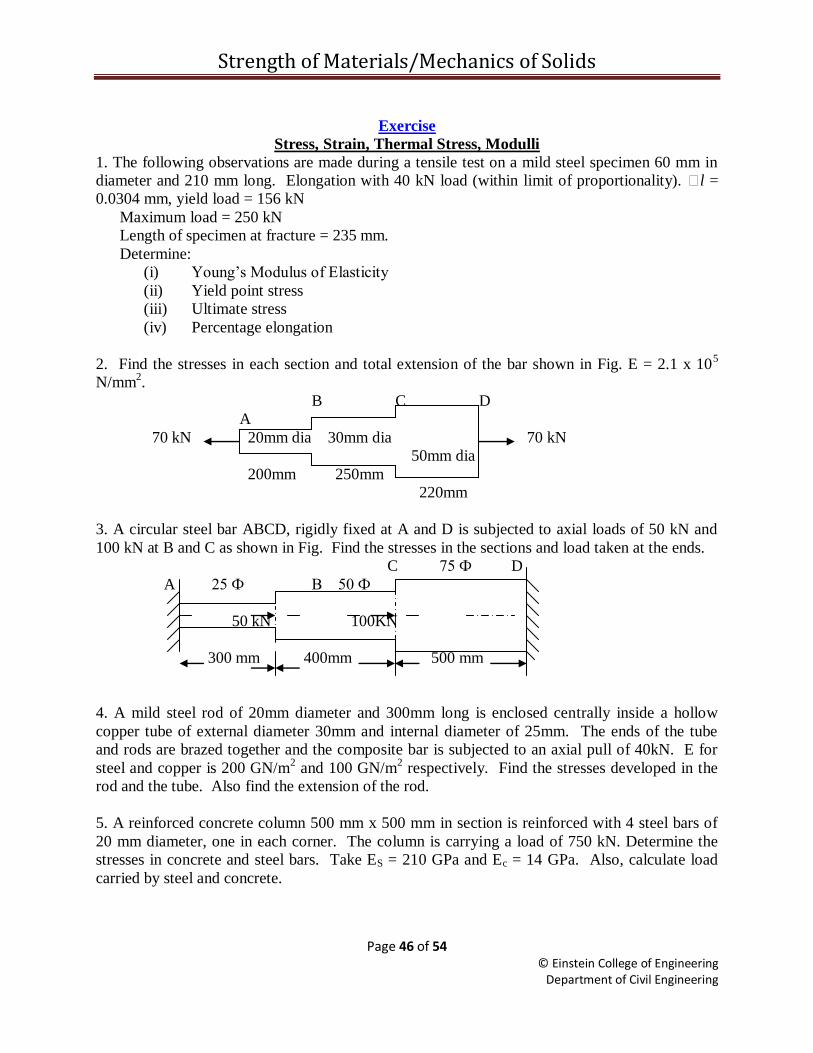
2. Find the stresses in each section and total extension of the bar shown in Fig. E = 2.1 x 10⁵
N/mm2.
B C D
A
70 kN 20mm dia 30mm dia 70 kN
50mm dia
200mm 250mm
220mm
3. A circular steel bar ABCD, rigidly fixed at A and D is subjected to axial loads of 50 kN and
100 kN at B and C as shown in Fig. Find the stresses in the sections and load taken at the ends.
C 75 Ф D
A 25 Ф B 50 Ф
50 kN 100KN
300 mm 400mm 500 mm
4. A mild steel rod of 20mm diameter and 300mm long is enclosed centrally inside a hollow
copper tube of external diameter 30mm and internal diameter of 25mm. The ends of the tube
and rods are brazed together and the composite bar is subjected to an axial pull of 40kN. E for
steel and copper is 200 GN/m2 and 100 GN/m
2 respectively. Find the stresses developed in the
rod and the tube. Also find the extension of the rod.
5. A reinforced concrete column 500 mm x 500 mm in section is reinforced with 4 steel bars of
20 mm diameter, one in each corner. The column is carrying a load of 750 kN. Determine the
stresses in concrete and steel bars. Take ES = 210 GPa and Ec = 14 GPa. Also, calculate load
carried by steel and concrete.
Strength of Materials/Mechanics of Solids
Page 47 of 54 © Einstein College of Engineering
Department of Civil Engineering
6. A solid steel bar 500 mm long and 50 mm diameter is placed inside an aluminum tube 75 mm
inside diameter and 100 mm outside diameter. The aluminum tube is 0.5 mm longer than the
steel bar. A compressive load of 600 kN is applied to the bar and cylinder through rigid plates.
Find stresses developed in the steel and aluminum, take Es = 200GPa and Ea = 70Gpa.
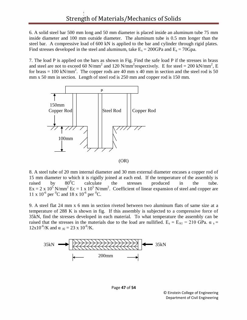
7. The load P is applied on the bars as shown in Fig. Find the safe load P if the stresses in brass
and steel are not to exceed 60 N/mm2 and 120 N/mm
2respectively. E for steel = 200 kN/mm
2, E
for brass = 100 kN/mm2. The copper rods are 40 mm x 40 mm in section and the steel rod is 50
mm x 50 mm in section. Length of steel rod is 250 mm and copper rod is 150 mm.
150mm
Copper Rod Steel Rod Copper Rod
100mm
(OR)
8. A steel tube of 20 mm internal diameter and 30 mm external diameter encases a copper rod of
15 mm diameter to which it is rigidly joined at each end. If the temperature of the assembly is
raised by 800C calculate the stresses produced in the tube.
Ex = 2 x 10⁵ N/mm
2 Ec = 1 x 10
5 N/mm
2. Coefficient of linear expansion of steel and copper are
11 x 10-6
per 0C and 18 x 10
-6 per
0C.
9. A steel flat 24 mm x 6 mm in section riveted between two aluminum flats of same size at a
temperature of 288 K is shown in fig. If this assembly is subjected to a compressive force of
35kN, find the stresses developed in each material. To what temperature the assembly can be
raised that the stresses in the materials due to the load are nullified. Es = EA1 = 210 GPa. α s =
12x10-6
/K and α Al = 23 x 10-6
/K.
35kN 35kN
200mm
P

Strength of Materials/Mechanics of Solids
Page 48 of 54 © Einstein College of Engineering
Department of Civil Engineering
10. A steel rod 5 m long and 25 mm in diameter is subjected to an axial tensile load of 50 kN.
Determine the change in length, diameter and volume of the rod. Take E = 2 x 10⁵ N/mm
2 and
Poisson‟s ratio = 0.30.
11. A rectangular bar is subjected to load as shown in the fig. Find the change in volume of the
bar. Take E =200 GPa and Poisson‟s ratio as 0.25
300kN 100mm
50mm 100kN
200kN 500 mm
12. A bar of 30mm diameter is subjected to a pull of 60kN. The measured extension on gauge
length of 200mm is 0.09mm and the change in diameter is 0.0039mm. Calculate μ and the
values of the three module.
13. A tensile load of 60kN is gradually applied to a circular bar of 4cm diameter and 5m long. If
the value of E = 2 x 10⁵ N/mm
2, determine
a. stretch in the rod
b. stress in the rod
c. strain energy absorbed by the rod
Find the above, if the same load is applied suddenly.
Shear Force and Bending Moment Diagram, Bending Stress, and Shear Stress
1. Draw SFD and BMD with all the salient features.
20 kN
10 kN/m
2m 3 m 2m 1m
2. Draw SFD and BMD with all the salient features.
20 kN
10 kN/m
1.5m 1.5m
2m 2m
3.Draw SFD and BMD with all the salient features.
Strength of Materials/Mechanics of Solids
Page 49 of 54 © Einstein College of Engineering
Department of Civil Engineering
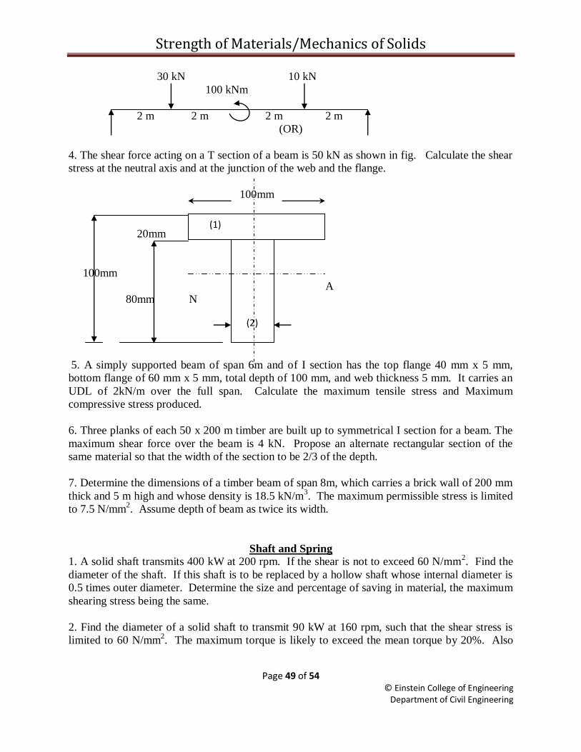
30 kN 10 kN
100 kNm
2 m 2 m 2 m 2 m
(OR)
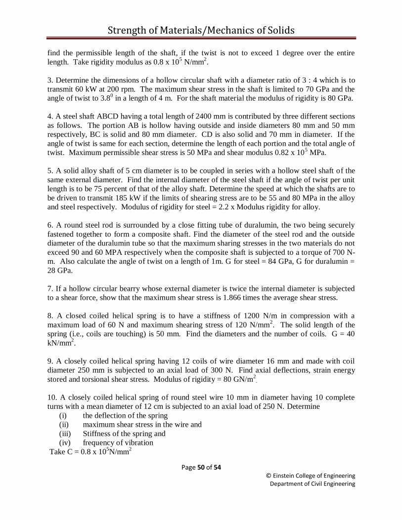
4. The shear force acting on a T section of a beam is 50 kN as shown in fig. Calculate the shear
stress at the neutral axis and at the junction of the web and the flange.
100mm
20mm
100mm
A
80mm N
5. A simply supported beam of span 6m and of I section has the top flange 40 mm x 5 mm,
bottom flange of 60 mm x 5 mm, total depth of 100 mm, and web thickness 5 mm. It carries an
UDL of 2kN/m over the full span. Calculate the maximum tensile stress and Maximum
compressive stress produced.
6. Three planks of each 50 x 200 m timber are built up to symmetrical I section for a beam. The
maximum shear force over the beam is 4 kN. Propose an alternate rectangular section of the
same material so that the width of the section to be 2/3 of the depth.
7. Determine the dimensions of a timber beam of span 8m, which carries a brick wall of 200 mm
thick and 5 m high and whose density is 18.5 kN/m3. The maximum permissible stress is limited
to 7.5 N/mm2. Assume depth of beam as twice its width.
Shaft and Spring 1. A solid shaft transmits 400 kW at 200 rpm. If the shear is not to exceed 60 N/mm
2. Find the
diameter of the shaft. If this shaft is to be replaced by a hollow shaft whose internal diameter is
0.5 times outer diameter. Determine the size and percentage of saving in material, the maximum
shearing stress being the same.
2. Find the diameter of a solid shaft to transmit 90 kW at 160 rpm, such that the shear stress is
limited to 60 N/mm2. The maximum torque is likely to exceed the mean torque by 20%. Also
(1)
(2)
20mm
Strength of Materials/Mechanics of Solids
Page 50 of 54 © Einstein College of Engineering
Department of Civil Engineering
find the permissible length of the shaft, if the twist is not to exceed 1 degree over the entire
length. Take rigidity modulus as 0.8 x 10⁵ N/mm
2.
3. Determine the dimensions of a hollow circular shaft with a diameter ratio of 3 : 4 which is to
transmit 60 kW at 200 rpm. The maximum shear stress in the shaft is limited to 70 GPa and the
angle of twist to 3.80 in a length of 4 m. For the shaft material the modulus of rigidity is 80 GPa.
4. A steel shaft ABCD having a total length of 2400 mm is contributed by three different sections
as follows. The portion AB is hollow having outside and inside diameters 80 mm and 50 mm
respectively, BC is solid and 80 mm diameter. CD is also solid and 70 mm in diameter. If the
angle of twist is same for each section, determine the length of each portion and the total angle of
twist. Maximum permissible shear stress is 50 MPa and shear modulus 0.82 x 10⁵ MPa.
5. A solid alloy shaft of 5 cm diameter is to be coupled in series with a hollow steel shaft of the
same external diameter. Find the internal diameter of the steel shaft if the angle of twist per unit
length is to be 75 percent of that of the alloy shaft. Determine the speed at which the shafts are to
be driven to transmit 185 kW if the limits of shearing stress are to be 55 and 80 MPa in the alloy
and steel respectively. Modulus of rigidity for steel = 2.2 x Modulus rigidity for alloy.
6. A round steel rod is surrounded by a close fitting tube of duralumin, the two being securely
fastened together to form a composite shaft. Find the diameter of the steel rod and the outside
diameter of the duralumin tube so that the maximum sharing stresses in the two materials do not
exceed 90 and 60 MPA respectively when the composite shaft is subjected to a torque of 700 N-
m. Also calculate the angle of twist on a length of 1m. G for steel = 84 GPa, G for duralumin =
28 GPa.
7. If a hollow circular bearry whose external diameter is twice the internal diameter is subjected
to a shear force, show that the maximum shear stress is 1.866 times the average shear stress.
8. A closed coiled helical spring is to have a stiffness of 1200 N/m in compression with a
maximum load of 60 N and maximum shearing stress of 120 N/mm2. The solid length of the
spring (i.e., coils are touching) is 50 mm. Find the diameters and the number of coils. G = 40
kN/mm2.
9. A closely coiled helical spring having 12 coils of wire diameter 16 mm and made with coil
diameter 250 mm is subjected to an axial load of 300 N. Find axial deflections, strain energy
stored and torsional shear stress. Modulus of rigidity = 80 GN/m2
.
10. A closely coiled helical spring of round steel wire 10 mm in diameter having 10 complete
turns with a mean diameter of 12 cm is subjected to an axial load of 250 N. Determine
(i) the deflection of the spring
(ii) maximum shear stress in the wire and
(iii) Stiffness of the spring and
(iv) frequency of vibration
Take C = 0.8 x 10⁵N/mm
2
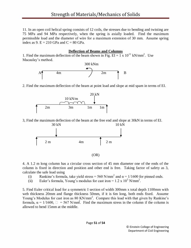
Strength of Materials/Mechanics of Solids
Page 51 of 54 © Einstein College of Engineering
Department of Civil Engineering
11. In an open coil helical spring consists of 12 coils, the stresses due to bending and twisting are
75 MPa and 94 MPa respectively, when the spring is axially loaded. Find the maximum
permissible load and the diameter of wire for a maximum extension of 30 mm. Assume spring
index as 9. E = 210 GPa and C = 80 GPa.
Deflection of Beams and Columns
1. Find the maximum deflection of the beam shown in Fig. EI = 1 x 10¹¹
kN/mm2. Use
Macaulay‟s method.
300 kNm
A 4m 2m B
2. Find the maximum deflection of the beam at point load and slope at mid spam in terms of EI.
20 kN
10 kN/m
2m 3m 1m 1m
3, Find the maximum deflection of the beam at the free end and slope at 30kN in terms of EI.
30 kN 10 kN
2 m 4m 2 m
(OR)
4. A 1.2 m long column has a circular cross section of 45 mm diameter one of the ends of the
column is fixed in direction and position and other end is free. Taking factor of safety as 3,
calculate the safe load using
(i) Rankine‟s formula, take yield stress = 560 N/mm2 and α = 1/1600 for pinned ends.
(ii) Euler‟s formula, Young‟s modulus for cast iron = 1.2 x 10⁵ N/mm
2.
5. Find Euler critical load for a symmetric I section of width 300mm x total depth 1100mm with
web thickness 20mm and flange thickness 50mm, if it is 6m long, both ends fixed. Assume
Young‟s Modulus for cast iron as 80 KN/mm2. Compare this load with that given by Rankine‟s
formula, α = 1/1600, = 567 N/mm2. Find the maximum stress in the column if the column is
allowed to bend 15mm at the middle.
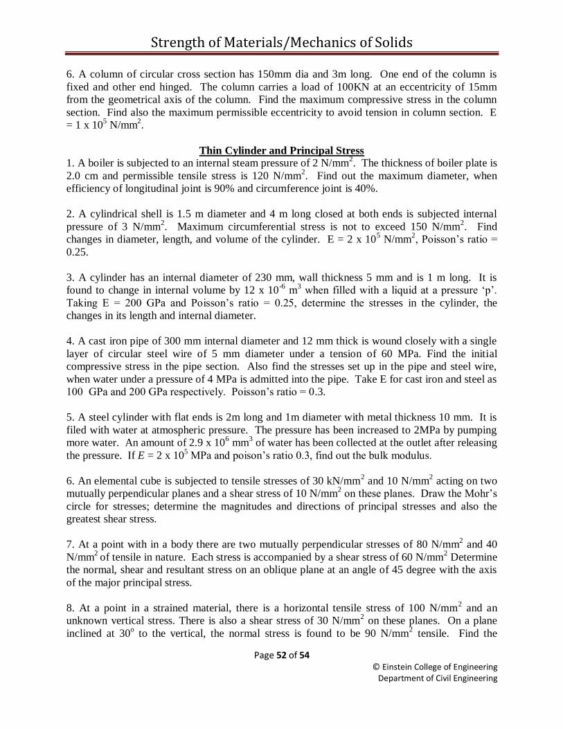
Strength of Materials/Mechanics of Solids
Page 52 of 54 © Einstein College of Engineering
Department of Civil Engineering
6. A column of circular cross section has 150mm dia and 3m long. One end of the column is
fixed and other end hinged. The column carries a load of 100KN at an eccentricity of 15mm
from the geometrical axis of the column. Find the maximum compressive stress in the column
section. Find also the maximum permissible eccentricity to avoid tension in column section. E
= 1 x 10⁵ N/mm
2.
Thin Cylinder and Principal Stress
1. A boiler is subjected to an internal steam pressure of 2 N/mm2. The thickness of boiler plate is
2.0 cm and permissible tensile stress is 120 N/mm2. Find out the maximum diameter, when
efficiency of longitudinal joint is 90% and circumference joint is 40%.
2. A cylindrical shell is 1.5 m diameter and 4 m long closed at both ends is subjected internal
pressure of 3 N/mm2. Maximum circumferential stress is not to exceed 150 N/mm
2. Find
changes in diameter, length, and volume of the cylinder. E = 2 x 10⁵ N/mm
2, Poisson‟s ratio =
0.25.
3. A cylinder has an internal diameter of 230 mm, wall thickness 5 mm and is 1 m long. It is
found to change in internal volume by 12 x 10-6
m3 when filled with a liquid at a pressure „p‟.
Taking E = 200 GPa and Poisson‟s ratio = 0.25, determine the stresses in the cylinder, the
changes in its length and internal diameter.
4. A cast iron pipe of 300 mm internal diameter and 12 mm thick is wound closely with a single
layer of circular steel wire of 5 mm diameter under a tension of 60 MPa. Find the initial
compressive stress in the pipe section. Also find the stresses set up in the pipe and steel wire,
when water under a pressure of 4 MPa is admitted into the pipe. Take E for cast iron and steel as
100 GPa and 200 GPa respectively. Poisson‟s ratio = 0.3.
5. A steel cylinder with flat ends is 2m long and 1m diameter with metal thickness 10 mm. It is
filed with water at atmospheric pressure. The pressure has been increased to 2MPa by pumping
more water. An amount of 2.9 x 106 mm
3 of water has been collected at the outlet after releasing
the pressure. If E = 2 x 10⁵ MPa and poison‟s ratio 0.3, find out the bulk modulus.
6. An elemental cube is subjected to tensile stresses of 30 kN/mm2 and 10 N/mm
2 acting on two
mutually perpendicular planes and a shear stress of 10 N/mm2 on these planes. Draw the Mohr‟s
circle for stresses; determine the magnitudes and directions of principal stresses and also the
greatest shear stress.
7. At a point with in a body there are two mutually perpendicular stresses of 80 N/mm2 and 40
N/mm2
of tensile in nature. Each stress is accompanied by a shear stress of 60 N/mm2 Determine
the normal, shear and resultant stress on an oblique plane at an angle of 45 degree with the axis
of the major principal stress.
8. At a point in a strained material, there is a horizontal tensile stress of 100 N/mm2 and an
unknown vertical stress. There is also a shear stress of 30 N/mm2 on these planes. On a plane
inclined at 30o to the vertical, the normal stress is found to be 90 N/mm
2 tensile. Find the
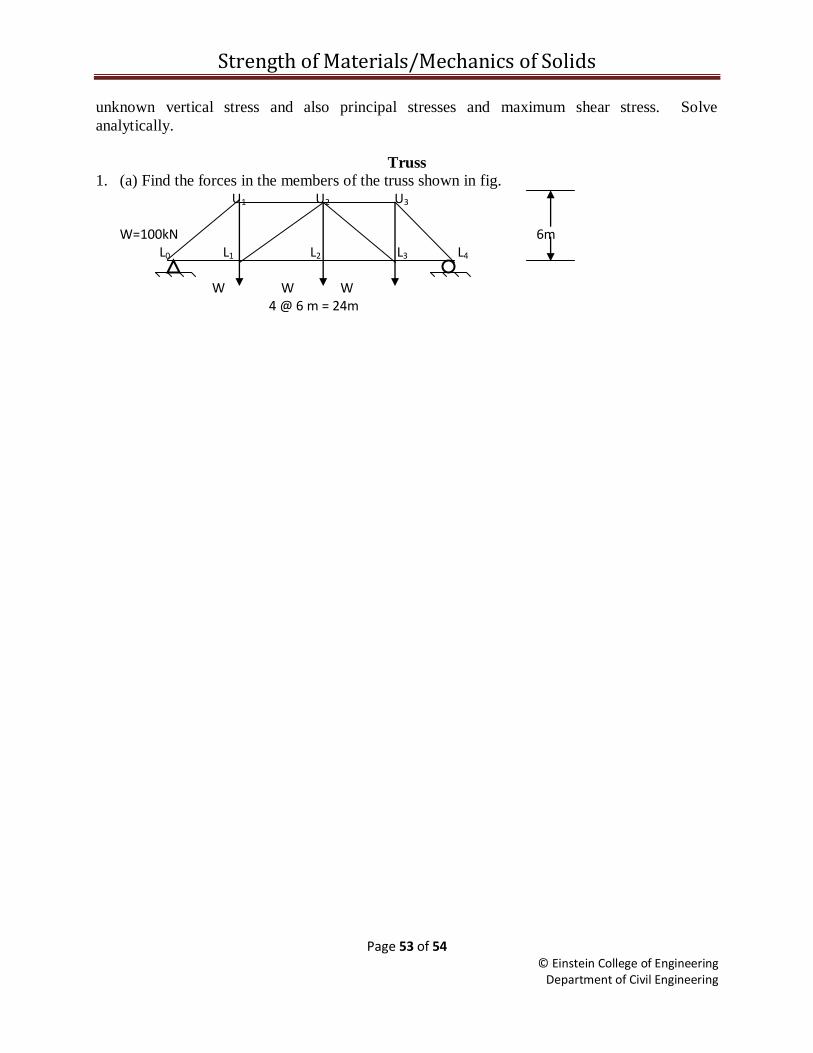
Strength of Materials/Mechanics of Solids
Page 53 of 54 © Einstein College of Engineering
Department of Civil Engineering
unknown vertical stress and also principal stresses and maximum shear stress. Solve
analytically.
Truss
1. (a) Find the forces in the members of the truss shown in fig. U1 U2 U3 W=100kN 6m L0 L1 L2 L3 L4
W W W 4 @ 6 m = 24m
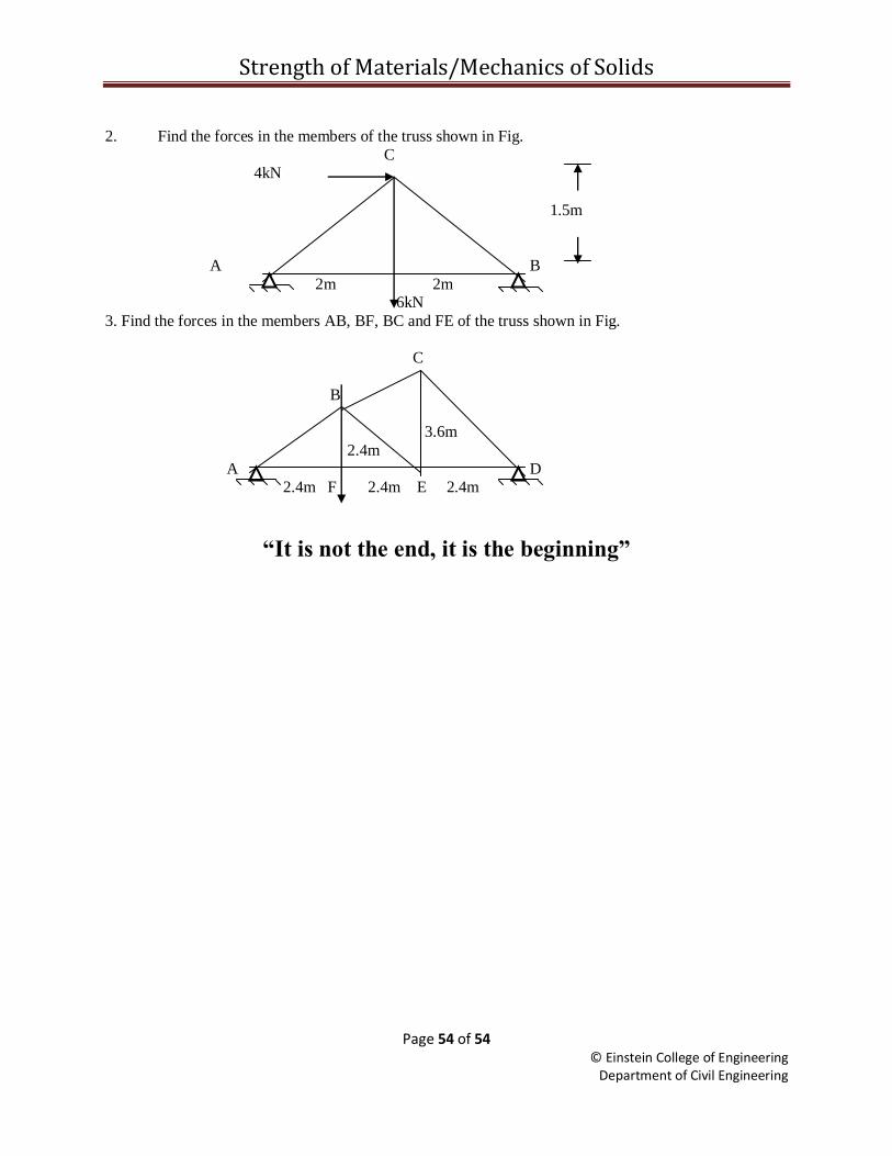
Strength of Materials/Mechanics of Solids
Page 54 of 54 © Einstein College of Engineering
Department of Civil Engineering
2. Find the forces in the members of the truss shown in Fig.
C 4kN
1.5m
A B
2m 2m 6kN
3. Find the forces in the members AB, BF, BC and FE of the truss shown in Fig.
C
B
3.6m
2.4m
A D 2.4m F 2.4m E 2.4m
“It is not the end, it is the beginning”