
Mechanics of Solids - icasfiles.comicasfiles.com/mechanics of solids/books/Bhavikatti SS - Mechanics...
384
Transcript of Mechanics of Solids - icasfiles.comicasfiles.com/mechanics of solids/books/Bhavikatti SS - Mechanics...


This pageintentionally left
blank


Copyright © 2010, New Age International (P) Ltd., PublishersPublished by New Age International (P) Ltd., Publishers
All rights reserved.No part of this ebook may be reproduced in any form, by photostat, microfilm, xerography,or any other means, or incorporated into any information retrieval system, electronic ormechanical, without the written permission of the publisher. All inquiries should beemailed to [email protected]
ISBN (13) : 978-81-224-2858-2
PUBLISHING FOR ONE WORLD
NEW AGE INTERNATIONAL (P) LIMITED, PUBLISHERS4835/24, Ansari Road, Daryaganj, New Delhi - 110002Visit us at www.newagepublishers.com

(v)
Preface
Mechanics of Solids is an important course for all engineering students bywhich they develop analytical skill. In this course, laws of mechanics are appliedto parts of bodies and skill is developed to get solution to engineering problemsmaintaining continuity of the parts.
The author has clearly explained theories involved and illustrated them bysolving a number of engineering problems. Neat diagrams are drawn andsolutions are given without skipping any step. SI units and standard notationsas suggested by Indian Standard Code are used throughout. The author hasmade this book to suit the latest syllabus of Gujarat Technical University.
Author hopes, the students and teachers of Gujarat Technical University willreceive this book whole-heartedly as most of the earlier books of the authorhave been received by the students and teachers all over India.
The suggestions and corrections, if any, are most welcome.
The author acknowledges the efforts of M/s. New Age International Publish-ers in bringing out this book in nice form. He also acknowledges the opportu-nity given by AICTE for associating him with B.U.B. Engineering College,Hubli.
—Author

This pageintentionally left
blank
Contents
Preface v
1 INTRODUCTION TO MECHANICS OF SOLIDS 1–14
1.1 Basic Terminologies in Mechanics ...............................................................................21.2 Units .............................................................................................................................51.3 Scalar and Vector Quantities .......................................................................................61.4 Composition and Resolution of Vectors .........................................................................6
Important Formulae ...................................................................................................13Theory Questions ........................................................................................................14Problems for Exercise .................................................................................................14
2 FUNDAMENTALS OF STATICS 15–64
2.1 Principles of Statics .................................................................................................... 152.2 System of Forces ......................................................................................................... 182.3 Moment of a Force ...................................................................................................... 182.4 Varignon’s Theorem ................................................................................................... 192.5 Couple ......................................................................................................................... 222.6 Transfer of a Force to Parallel Position ..................................................................... 232.7 Composition of Concurrent Coplanar Forces.............................................................. 232.8 Equilibriant of a Force System .................................................................................. 282.9 Composition of Coplanar Non-concurrent Force System ........................................... 282.10 X and Y Intercepts of Resultant ................................................................................. 292.11 Types of Forces on a Body .......................................................................................... 382.12 Free Body Diagram .................................................................................................... 402.13 Equilibrium of Bodies ................................................................................................. 402.14 Equilibrium of Concurrent Force Systems ................................................................ 412.15 Equilibrium of Connected Bodies ............................................................................... 472.16 Equilibrium of Non-concurrent Force Systems ......................................................... 53
Important Formulae ...................................................................................................57Theory Questions ........................................................................................................58Problems for Exercise .................................................................................................59
3 TRUSSES 65–93
3.1 Perfect, Deficient and Redundant Trusses ................................................................ 653.2 Assumptions ............................................................................................................... 663.3 Nature of Forces in Members ..................................................................................... 673.4 Methods of Analysis .................................................................................................... 683.5 Method of Joints ......................................................................................................... 683.6 Method of Section ........................................................................................................ 81
Important Formula ....................................................................................................87Theory Questions ........................................................................................................87Problems for Exercise .................................................................................................88
4 DISTRIBUTED FORCES, CENTRE OF GRAVITY AND MOMENT 94–160OF INERTIA
4.1 Determination of Areas and Volumes......................................................................... 944.2 Centre of Gravity and Centroids ................................................................................ 994.3 Centroid of a Line ..................................................................................................... 1004.4 First Moment of Area and Centroid ......................................................................... 1044.5 Second Moments of Plane Area ................................................................................ 1194.6 Moment of Inertia from First Principles .................................................................. 1224.7 Moment of Inertia of Composite Sections ................................................................. 1294.8 Theorems of Pappus-Guldinus ................................................................................. 1424.9 Centre of Gravity of Solids ....................................................................................... 146
Important formulae .................................................................................................. 151Theory Questions ...................................................................................................... 152Problems for Exercise ............................................................................................... 152
5 FRICTION 161–190
5.1 Coefficient of Friction ............................................................................................... 1615.2 Laws of Friction ....................................................................................................... 1625.3 Angle of Friction, Angle of Repose and Cone of Friction .......................................... 1625.4 Problems on Blocks Resting on Horizontal and Inclined Planes ............................. 1645.5 Application to Wedge Problems ................................................................................ 1745.6 Application to Ladder Problems ............................................................................... 1775.7 Belt Friction ............................................................................................................. 180
Important Formulae ................................................................................................. 187Theory Questions ...................................................................................................... 187Problems for Exercise ............................................................................................... 187
6 SIMPLE MACHINES 191–227
6.1 Definitions ................................................................................................................ 1916.2 Practical Machines ................................................................................................... 1926.3 Law of Machine ........................................................................................................ 1946.4 Variation of Mechanical Advantage ......................................................................... 1956.5 Variation of Efficiency .............................................................................................. 195
CONTENTS
6.6 Reversibility of a Machine ........................................................................................ 1996.7 Lever Arm ................................................................................................................ 2006.8 Pulleys ...................................................................................................................... 2016.9 Wheel and Axle ......................................................................................................... 2056.10 Wheel and Differential Axle ..................................................................................... 2056.11 Weston Differential Pulley Block ............................................................................. 2066.12 Inclined Plane ........................................................................................................... 2086.13 Screw Jack................................................................................................................ 2136.14 Differential Screw Jack ............................................................................................ 2186.15 Winch Crabs ............................................................................................................. 219
Important Formulae ................................................................................................. 223Theory Questions ...................................................................................................... 224Problems for Exercise ............................................................................................... 225
7 PHYSICAL AND MECHANICAL PROPERTIES OF 228–233STRUCTURAL MATERIALS
7.1 Physical Properties ................................................................................................... 2287.2 Mechanical Properties .............................................................................................. 229
Theory Questions ...................................................................................................... 233
8 SIMPLE STRESSES AND STRAINS 234–282
8.1 Meaning of Stress ..................................................................................................... 2348.2 Unit of Stress ........................................................................................................... 2368.3 Axial Stress .............................................................................................................. 2368.4 Strain ........................................................................................................................ 2378.5 Stress-Strain Relation .............................................................................................. 2388.6 Nominal Stress and True Stress .............................................................................. 2418.7 Factor of Safety......................................................................................................... 2428.8 Hooke’s Law ............................................................................................................. 2428.9 Extension/Shortening of a Bar ................................................................................. 2438.10 Bars with Cross-sections Varying in Steps .............................................................. 2468.11 Bars with Continuously Varying Cross-sections ...................................................... 2488.12 Shear Stress ............................................................................................................. 2538.13 Simple Shear ............................................................................................................ 2538.14 Poisson’s Ratio .......................................................................................................... 2558.15 Volumetric Strain ..................................................................................................... 2558.16 Elastic Constants ...................................................................................................... 2568.17 Relationship between Modulus of Elasticity and Modulus of Rigidity ..................... 2578.18 Relationship between Modulus of Elasticity and Bulk Modulus .............................. 2588.19 Composite/Compound Bars ....................................................................................... 2648.20 Thermal Stresses ...................................................................................................... 2698.21 Thermal Stresses in Compound Bars ....................................................................... 2748.22 Hoop Stresses ........................................................................................................... 277
CONTENTS

Important Formulae ................................................................................................. 278Theory Questions ...................................................................................................... 279Problems for Exercise ............................................................................................... 280
9 BEAMS 283–312
9.1 Introduction .............................................................................................................. 2839.2 Types of Supports ..................................................................................................... 2839.3 Types of Beams ......................................................................................................... 2849.4 Types of Loading ....................................................................................................... 2859.5 Reactions from Supports of Beams ........................................................................... 2869.6 Shear Force and Bending Moment ........................................................................... 2919.7 Sign Convention ....................................................................................................... 2939.8 Relationship between Load Intensity, Shear Force and Bending Moment .............. 2939.9 Shear Force and Bending Moment Diagrams .......................................................... 2949.10 SFD and BMD for a few Standard Cases ................................................................. 2959.11 Short-cut Procedure .................................................................................................. 307
Important Formulae ................................................................................................. 310Theory Questions ...................................................................................................... 310Problems for Exercise ............................................................................................... 310
10 STRESSES IN BEAMS 313–345
10.1 Assumptions ........................................................................................................... 31410.2 Bending Equation ................................................................................................... 31410.3 Locating Neutral Axis ............................................................................................ 31610.4 Moment Carrying Capacity of a Section ................................................................. 31710.5 Section Moduli of Standard Sections ...................................................................... 31810.6 Proportioning Sections ............................................................................................ 32910.7 Shear Stress Distribution ....................................................................................... 33010.8 Shear Stresses in Built-up Sections ....................................................................... 338
Important Formulae ................................................................................................. 342Theory Questions ...................................................................................................... 343Problems for Exercise ............................................................................................... 343
11 PRINCIPAL STRESSES AND STRAINS 346–373
11.1 Stresses on Inclined Planes .................................................................................... 34611.2 Principal Stresses and Planes ................................................................................ 34811.3 Principal Stresses in Beams .................................................................................... 36011.4 Principal Strains ...................................................................................................... 36511.5 Measurement of Strain ............................................................................................. 368
Important Formulae ................................................................................................. 371Theory Questions ...................................................................................................... 372Problems for Exercise ............................................................................................... 372
CONTENTS
1Introduction to
Mechanics of Solids
The state of rest and the state of motion of the bodies under the action of different forces hasengaged the attention of mathematicians and scientists for many centuries. The branch of physicalscience that deal with the state of rest or the state of motion of bodies is termed as mechanics.Starting from the analysis of rigid bodies under gravitational force and application of simple forcesthe mechanics has grown into the analysis of complex structures like multistorey buildings, aircrafts,space crafts and robotics under complex system of forces like dynamic forces, atmospheric forcesand temperature forces.
Archemedes (287–212 BC), Galileo (1564–1642), Sir Issac Newton (1642–1727) and Einstein(1878–1955) have contributed a lot to the development of mechanics. Contributions by Varignon,Euler, and D. Alemberts are also substantial. The mechanics developed by these researchers maybe grouped as
(i) Classical mechanics/Newtonian mechanics
(ii) Relativistic mechanics
(iii) Quantum mechanics/Wave mechanics.
Sir Issac Newton, the principal architect of mechanics, consolidated the philosophy and experimentalfindings developed around the state of rest and state of motion of the bodies and putforth them inthe form of three laws of motion as well as the law of gravitation. The mechanics based on theselaws is called Classical mechanics or Newtonian mechanics.
Albert Einstein proved that Newtonian mechanics fails to explain the behaviour of high speed(speed of light) bodies. He putfourth the theory of Relativistic mechanics.
Schrödinger (1887–1961) and Broglie (1892–1965) showed that Newtonian mechanics fails toexplain the behaviour of particles when atomic distances are concerned. They putforth the theoryof Quantum mechanics.
Engineers are keen to use the laws of mechanics to actual field problems. Application of lawsof mechanics to field problems is termed as Engineering mechanics. For all the problems betweenatomic distances to high speed distances there are various engineering problems for which Newtonianmechanics has stood the test of time and hence is the mechanics used by engineers.
The various bodies on which engineers are interested to apply laws of mechanics may beclassified as
(i) Solids and(ii) Fluids.
1

2 MECHANICS OF SOLIDS
The bodies which do not change their shape or size appreciably when the forces are appliedare termed as Solids while the bodies which change their shape or size appreciably even when smallforces are applied are termed as Fluids. Stone, steel, concrete etc. are the example of solids whilewater, gases are the examples of fluids.
In this book application of Newtonian mechanics to solids is dealt with.
1.1 BASIC TERMINOLOGIES IN MECHANICS
The following are the terms basic to the study of mechanics, which should be understood clearly.
Mass
The quantity of the matter possessed by a body is called mass. The mass of a body will not changeunless the body is damaged and part of it is physically separated. If the body is taken out in a spacecraft, the mass will not change but its weight may change due to the change in gravitational force.The body may even become weightless when gravitational force vanishes but the mass remain thesame.
Time
The time is the measure of succession of events. The successive event selected is the rotation ofearth about its own axis and this is called a day. To have convenient units for various activities,a day is divided into 24 hours, an hour into 60 minutes and a minute into 60 seconds. Clocks arethe instruments developed to measure time. To overcome difficulties due to irregularities in theearths rotation, the unit of time is taken as second which is defined as the duration of 9192631770period of radiation of the cesium-133 atom.
Space
The geometric region in which study of body is involved is called space. A point in the space maybe referred with respect to a predetermined point by a set of linear and angular measurements. Thereference point is called the origin and the set of measurements as coordinates. If the coordinatesinvolved are only in mutually perpendicular directions, they are known as cartesian coordination.If the coordinates involve angles as well as the distances, it is termed as Polar Coordinate System.
Length
It is a concept to measure linear distances. The diameter of a cylinder may be 300 mm, the heightof a building may be 15 m, the distance between two cities may be 400 km.Actually metre is the unit of length. However depending upon the sizes involved micro, milli or kilometre units are used for measurements. A metre is defined as length of the standard bar ofplatinum-iradium kept at the International Bureau of weights and measures. To overcome thedifficulties of accessibility and reproduction now metre is defined as 1690763.73 wavelength ofkrypton-86 atom.
Continuum
A body consists of several matters. It is a well known fact that each particle can be subdividedinto molecules, atoms and electrons. It is not possible to solve any engineering problem by treatinga body as conglomeration of such discrete particles. The body is assumed to be a continuousdistribution of matter. In other words the body is treated as continuum.

INTRODUCTION TO MECHANICS OF SOLIDS 3
Rigid Body
A body is said to be rigid, if the relative positions of any two particles do not change under theaction of the forces acting on it. In Fig. 1.1 (a), point A and B are the original positions in a body.After the application of forces F1, F2, F3, the body takes the position as shown in Fig. 1.1(b). A′and B′ are the new positions of A and B. If the body is treated as rigid, the relative position of A′B′and AB are the same i.e.
A′B′ = AB
Many engineering problems can be solved by assuming bodies rigid
B
A
B′
A′F1
F2
F3
(a) (b)
Fig. 1.1
Particle
A particle may be defined as an object which has only mass and no size. Theoretically speakingsuch a body cannot exist. However in dealing with problems involving distances considerably largercompared to the size of the body, the body may be treated as a particle, without sacrificingaccuracy.
For example:
— A bomber aeroplane is a particle for a gunner operating from the ground.— A ship in mid sea is a particle in the study of its relative motion from a control tower.
— In the study of movement of the earth in celestial sphere, earth is treated as a particle.
Force
Force is an important term used in solid mechanics. Newton’s first law states that everybodycontinues in its state of rest or of uniform motion in a straight line unless it is compelled by anexternal agency acting on it. This leads to the definition of force as ‘force is an external agencywhich changes or tends to change the state of rest or uniform linear motion of the body’.
Magnitude of force is defined by Newton’s second law. It states that the rate of change ofmomentum of a body is directly proportional to the impressed force and it takes place in thedirection of the force acting on it. Noting that rate of change of velocity is acceleration, and theproduct of mass and velocity is momentum we can derive expression for the force as given below:
From Newton’s second law of motion Force ∝ rate of change of momentum
∝ rate of change of (mass × velocity)

4 MECHANICS OF SOLIDS
Since mass do not change,
Force ∝ mass × rate of change of velocity∝ mass × acceleration
F ∝ m × a ...(1.1)
= k × m × a
where F is the force, m is the mass and a is the acceleration and k is the constant of proportionality.
In all the systems, unit of force is so selected that the constant of the proportionality becomesunity. For example, in S.I. system, unit of force is Newton, which is defined as the force that isrequired to move one kilogram (kg) mass at an acceleration of 1 m/sec2.
∴ One newton = 1 kg mass × 1 m/sec2
Thus k = 1F = m × a ...(1.2)
However in MKS acceleration used is one gravitational acceleration (9.81 m/sec2 on earthsurface) and unit of force is defined as kg-wt.
ThusF in kg wt = m × g ...(1.3)
Thus 1 kg-wt = 9.81 newtons ...(1.4)It may be noted that in usage kg-wt is often called as kg only.
Characteristics of a Force
It may be noted that a force is completely specified only when thefollowing four characteristics are specified
— Magnitude— Point of application
— Line of action— Direction.
In Fig. 1.2, AB is a ladder kept against a wall. At point C, a personweighing 600 N is standing. The force applied by the person on theladder has the following characters:
— magnitude is 600 N
— the point of application is C which is at 2 m from A along theladder
— the line of action is vertical— the direction is downward.
It may be noted that in the figure— magnitude is written near the arrow
— the line of arrow shows the line of application— the arrow head shows the point of application— the direction of arrow represents the direction of the force.
600 N
C
B
A
2m
2m
Fig. 1.2

INTRODUCTION TO MECHANICS OF SOLIDS 5
1.2 UNITS
Length (L), mass (M) and time (S) are the fundamental units used in mechanics. The units of allother quantities may be expressed in terms of these basic units. The three commonly used systemsare
— Metre, Kilogram, Second (MKS)
— Centimetre, Gram, Second (CGS)— Foot, Pound, Second (FPS).
The systems are named after the units used to define the fundamental quantities length, massand time. Using these basic units, the units of other quantities can be found. For example in MKSthe units for various quantities are
Quantity UnitArea m2
Volume m3
Velocity m/secAcceleration m/sec2
Momentum kg-m/sec [Since it is = mass × velocity]Force kg-m/sec2 [Since it is = mass × acceleration]
S.I. Units
Presently the whole world is in the process of switching over to SI-system of units. SI units standsfor the System International d′ units or International System of units. As in MKS units in SI alsothe fundamental units are metre for length, kilogram for mass and second for time. The differencebetween MKS and SI system arises mainly in selecting the unit of force. In MKS unit of force iskg-wt while in SI units it is newton. As we have already seen one kg-wt is equal to 9.81 newtons.
The prefixes used in SI when quantities are too big or too small are shown in Table 1.1.
Table 1.1. Prefixes in SI Units
Multiplying Factors Prefix Symbol
1012 tera T
109 giga G
106 mega M
103 kilo k
100 — —
10–3 milli m
10–6 micro m
10–9 nano n
10–12 pico p
10–15 femto f
10–18 atto a

6 MECHANICS OF SOLIDS
1.3 SCALAR AND VECTOR QUANTITIES
Various quantities used in mechanics may be grouped into scalars and vectors. A quantity is saidto be scalar, if it is completely defined by its magnitude alone. Examples of scalars are length, area,time and mass.
A quantity is said to be vector if it is completely defined only when its magnitude as well asdirection are specified. The example of vectors are displacement, velocity, acceleration, momentum,force etc.
1.4 COMPOSITION AND RESOLUTION OF VECTORS
The process of finding a single vector which will have the same effect as a set of vectors actingon a body is known as composition of vectors. The resolution of vectors is exactly the oppositeprocess of composition i.e., it is the process of finding two or more vectors which will have thesame effect as that of a vector acting on the body.
Parallelogram Law of Vectors
The parallelogram law of vectors enables us to determine the single vector called resultant vectorwhich can replace the two vectors acting at a point with the same effect as that of the two vectors.This law was formulated based on exprimental results on a body subjected to two forces. This lawcan be applied not only to the forces but to any two vectors like velocities, acceleration, momentumetc. Though stevinces employed it in 1586, the credit of presenting it as a law goes to Varignonand Newton (1687). This law states that if two forcer (vectors) acting simultaneously on a bodyat a point are represented in magnitude and directions by the two adjacent sides of a parallelogram,their resultant is represented in magnitude and direction by the diagonal of the parallelogram whichpasses thorough the point of intersection of the two sides representing the forces (vectors).
In the Fig. 1.3, the force F1 = 4 units and the force F2 = 3 unit are acting on a body at apoint A. To get the resultant of these forces, according to this law, construct the parallelogramABCD such that AB is equal to 4 units to the linear scale and AC is equal to 3 units. Then accordingto this law, the diagonal AD represents the resultant in magnitude and direction. Thus the resultantof the forces F1 and F2 is equal to the units corresponding to AD in the direction α to F1.
F2
F1 α
θ
44
R
A B
33
C D
(a) (b)
R
(c)
θ
Fig. 1.3
INTRODUCTION TO MECHANICS OF SOLIDS 7
Triangle Law of Vectors
Referring to Fig. 1.3 (b), it can be observed that the resultant AD may be obtained by constructingthe triangle ABD. Line AB is drawn to represent F1 and BD to represent F2. Then AD shouldrepresent the resultant of F1 and F2. Thus we have derived the triangle law of forces from thefundamental law of parallelogram. The Triangle Law of Forces (vectors) may be stated as if twoforces (vectors) acting on a body are represented one after another by the sides of a triangle, theirresultant is represented by the closing side of the triangle taken from the first point to the last point.
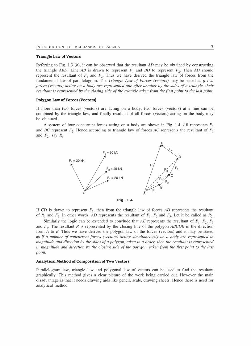
Polygon Law of Forces (Vectors)
If more than two forces (vectors) are acting on a body, two forces (vectors) at a line can becombined by the triangle law, and finally resultant of all forces (vectors) acting on the body maybe obtained.
A system of four concurrent forces acting on a body are shown in Fig. 1.4. AB represents F1and BC represent F2. Hence according to triangle law of forces AC represents the resultant of F1and F2, say R1.
F = 30 kN4
F = 30 kN3
F = 25 kN2
F = 20 kN1
O
E
F4
D
F3
F2
F1A
R2R2
R1R1
C
B
R
Fig. 1.4
If CD is drawn to represent F3, then from the triangle law of forces AD represents the resultantof R1 and F3. In other words, AD represents the resultant of F1, F2 and F3. Let it be called as R2.
Similarly the logic can be extended to conclude that AE represents the resultant of F1, F2, F3and F4. The resultant R is represented by the closing line of the polygon ABCDE in the directionform A to E. Thus we have derived the polygon law of the forces (vectors) and it may be statedas if a number of concurrent forces (vectors) acting simultaneously on a body are represented inmagnitude and direction by the sides of a polygon, taken in a order, then the resultant is representedin magnitude and direction by the closing side of the polygon, taken from the first point to the lastpoint.
Analytical Method of Composition of Two Vectors
Parallelogram law, triangle law and polygonal law of vectors can be used to find the resultantgraphically. This method gives a clear picture of the work being carried out. However the maindisadvantage is that it needs drawing aids like pencil, scale, drawing sheets. Hence there is need foranalytical method.
8 MECHANICS OF SOLIDS
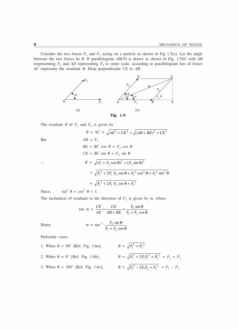
Consider the two forces F1 and F2 acting on a particle as shown in Fig 1.5(a). Let the anglebetween the two forces be θ. If parallelogram ABCD is drawn as shown in Fig. 1.5(b) with ABrespresenting F1 and AD representing F2 to some scale, according to parallelogram law of forcesAC represents the resultant R. Drop perpendicular CE to AB.
�
F2
F1O A
��
B
D C
R
E
�
F2
F2
F1
(a) (b)
Fig. 1.5
The resultant R of F1 and F2 is given by
R = AC = AE CE AB BE CE2 2 2 2+ = + +( )
But AB = F1
BE = BC cos θ = F2 cos θ
CE = BC sin θ = F2 sin θ
∴ R = ( cos ) ( sin )F F F1 22
22+ +θ θ
= F F F F F12
1 2 22 2
22 22+ + +cos cos sinθ θ θ
= F F F F12
1 2 222+ +cos θ
Since, sin2 θ + cos2 θ = 1.
The inclination of resultant to the direction of F1 is given by α, where
tan α = CE
AE
CE
AB BE
F
F F=
+=
+2
1 2
sin
cos
θθ
Hence α = tan–1 F
F F2
1 2
sin
cos
θθ+
Particular cases:
1. When θ = 90° [Ref. Fig. 1.6a], R = F F12
22+
2. When θ = 0° [Ref. Fig. 1.6b], R = F F F F12
1 22
222+ + = F1 + F2
3. When θ = 180° [Ref. Fig. 1.6c], R = F F F F12
1 2 222− + = F1 – F2

INTRODUCTION TO MECHANICS OF SOLIDS 9
F2
R
(a)
F1 F2
(b)
F1 F2
(c)
F1
Fig. 1.6
Resolution of Vectors
Since the resolution of vectors is exactly opposite process of composition of vectors, exactly theopposite process of composition can be employed to get the resolved components of a given force.
βα
F1 F
F2
θ α β= +
β
α
FF2
F1
(a)
F4F3
F2
F1
F F F4
F3
F2
F1
Fy
F2
F
Fy
Fx
F
(b)
(c)
Fig. 1.7
In Fig. 1.7(a), the given force F is resolved into two components making angles α and β with F.
In Fig. 1.7(b) the force F is resolved into its rectangular components Fx and Fy.In Fig. 1.7(c), the force F is resolved into its four components F1, F2, F3 and F4.It may be noted that all component forces act at the same point as the given force. Resolution
of forces into its rectangular components is more useful in solving the problems in mechanics. Inthis case, if the force F makes angle θ with x-axis, from Fig. 1.7(a), it is clear that
Fx = F cos θ and Fy = F sin θ.

10 MECHANICS OF SOLIDS
Example 1.1. A boat is rowed at a velocity of 20 km/hour across a river. The velocity of streamis 8 km/hour. Determine the resultant velocity of the boat.
Solution: Taking downstream direction as x and direction across the river as y, it is given thatVx = 8 km/hour
Vy = 20 km/hour∴ The resultant velocity
V = 8 202 2+ = 21.54 km/hour
ααααα = tan–1 V
Vy
x
= tan–1 20
8 = 68.20°, as shown in Fig. 1.8
�
V=
20 k
m/h
our
y
V = 8 km/hourx
V Downstream
Fig. 1.8
Example. 1.2. The guy wire of the electrical pole shown in Fig. 1.9(a) makes 60° to the horizontaland is carrying a force of 60 kN. Find the horizontal and vertical components of the force.
60°
FFy
Fx
(a) (b)
20kN
60°
Fig. 1.9
Solution: Figure 1.9(b) shows the resolution of force F = 20 kN into its components in horizontaland vertical components. From the figure it is clear that
Fx = F cos 60° = 20 cos 60° = 10 kN (to the left)Fy = F sin 60° = 20 sin 60° = 17.32 kN (downward)
INTRODUCTION TO MECHANICS OF SOLIDS 11
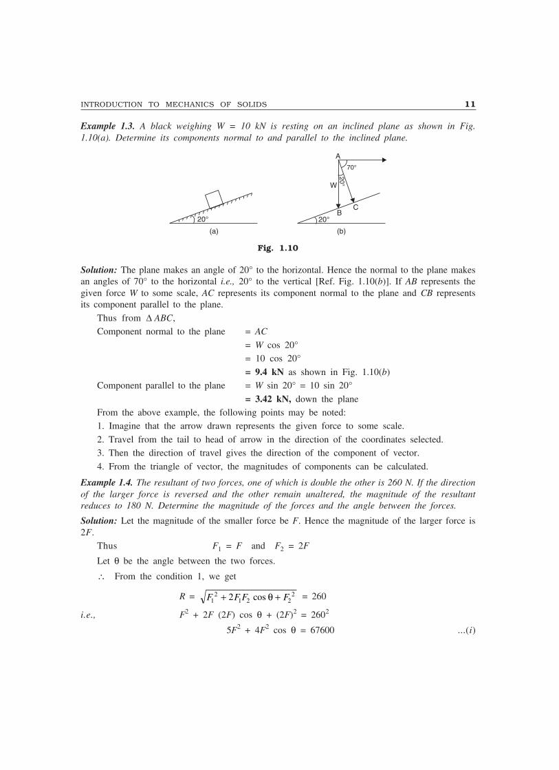
Example 1.3. A black weighing W = 10 kN is resting on an inclined plane as shown in Fig.1.10(a). Determine its components normal to and parallel to the inclined plane.
20°
W
20°20°
70°
CB
(a) (b)
A
Fig. 1.10
Solution: The plane makes an angle of 20° to the horizontal. Hence the normal to the plane makesan angles of 70° to the horizontal i.e., 20° to the vertical [Ref. Fig. 1.10(b)]. If AB represents thegiven force W to some scale, AC represents its component normal to the plane and CB representsits component parallel to the plane.
Thus from ∆ ABC,Component normal to the plane = AC
= W cos 20°= 10 cos 20°
= 9.4 kN as shown in Fig. 1.10(b)Component parallel to the plane = W sin 20° = 10 sin 20°
= 3.42 kN, down the planeFrom the above example, the following points may be noted:1. Imagine that the arrow drawn represents the given force to some scale.
2. Travel from the tail to head of arrow in the direction of the coordinates selected.3. Then the direction of travel gives the direction of the component of vector.
4. From the triangle of vector, the magnitudes of components can be calculated.
Example 1.4. The resultant of two forces, one of which is double the other is 260 N. If the directionof the larger force is reversed and the other remain unaltered, the magnitude of the resultantreduces to 180 N. Determine the magnitude of the forces and the angle between the forces.
Solution: Let the magnitude of the smaller force be F. Hence the magnitude of the larger force is2F.
Thus F1 = F and F2 = 2F
Let θ be the angle between the two forces.
∴ From the condition 1, we get
R = F F F F12
1 2 222+ +cos θ = 260
i.e., F2 + 2F (2F) cos θ + (2F)2 = 2602
5F2 + 4F2 cos θ = 67600 ...(i)

12 MECHANICS OF SOLIDS
From condition 2, we get
F F F F12
1 2 222 180+ + +cos ( )θ = 180
F2 – 2F(2F) cos θ + (2F)2 = 32400 ...(ii)
Adding equation (i) and (ii), we get10F2 = 100000
∴ F = 100 NHence F1 = F = 100 N; F2 = 2F = 200 NSubstituting the values of F1 and F2 in eqn (i), we get,
5(100)2 + 4(100)2 cos θ = 67600
∴ cos θ = 0.44or θθθθθ = 63.9°
Example 1.5. Two forces F1 and F2 are acting at point A asshown in Fig. 1.11. The angle between the two forces is 50°.It is found that the resultant R is 500 N and makes angles 20°with the force F1 as shown in the figure. Determine the forcesF1 and F2.
Solution: Let ∆ ABC be the triangle of forces drawn to somescale. In this
∠BAC = α = 20°
∠ABC = 180 – 50 = 130°∴ ∠ACB = 180 – (20 + 130) = 30°
Applying sine rule to ∆ ABC, we get
AB BC
sin sin sin30 20
500
130°=
°=
°∴ AB = 326.35 N
and BC = 223.24 N.
Thus F1 = AB = 326.35 Nand F2 = BC = 223.24 N
Example 1.6. The resultant of two forces F1 = 400 N andF2 = 260 N acting at point A is 520 N. Determine theangle between the two forces and the angle between theresultant and force F1.
Solution: Let ABC be the triangle of forces as shown inFig. 1.12. θ be the angle between F1 and F2, and α be theangle between resultant and F1
Using the relation
R = F F F F12
22
1 22+ + cos θ ,
we get,5202 = 4002 + 2602 + 2 × 400 × 260 × cos θ
50°
F2
F1A B
C
� = 50°
� = 20°
R
Fig. 1.11
�
F2
A B
C
�
R = 520 N
F = 260 N2
F = 400 N1
Fig. 1.12
INTRODUCTION TO MECHANICS OF SOLIDS 13
∴ cos θ = 0.20577
∴ θθθθθ = 78.13°Noting that
R sin α = F2 sin θ
we get sin α = 260 sin 78.13
520
° = 0.489
∴ ααααα = 29.29°
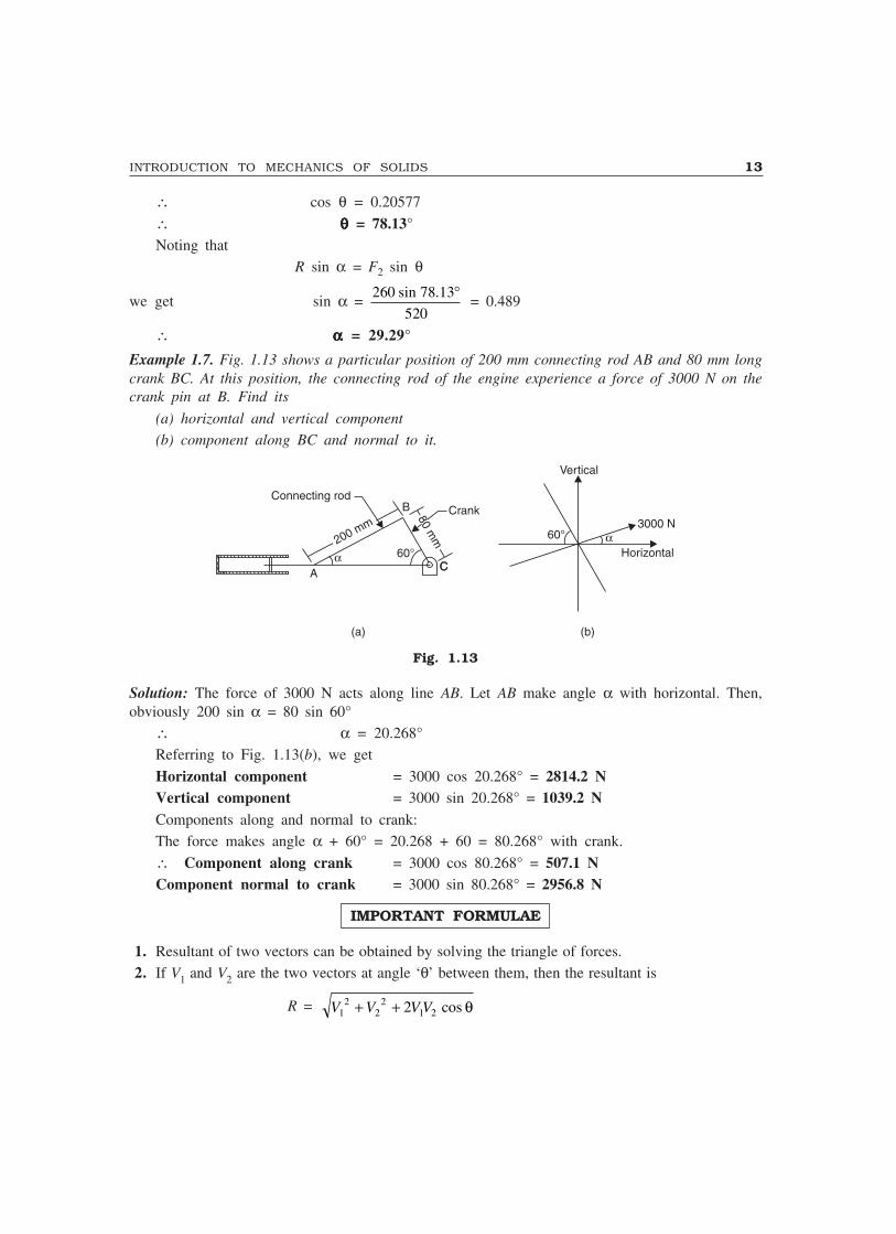
Example 1.7. Fig. 1.13 shows a particular position of 200 mm connecting rod AB and 80 mm longcrank BC. At this position, the connecting rod of the engine experience a force of 3000 N on thecrank pin at B. Find its
(a) horizontal and vertical component
(b) component along BC and normal to it.
�200 mm
B
80m
m
60°
Connecting rod
ACC
Crank
(a)
60° �
Vertical
Horizontal
3000 N
(b)
Fig. 1.13
Solution: The force of 3000 N acts along line AB. Let AB make angle α with horizontal. Then,obviously 200 sin α = 80 sin 60°
∴ α = 20.268°Referring to Fig. 1.13(b), we get
Horizontal component = 3000 cos 20.268° = 2814.2 NVertical component = 3000 sin 20.268° = 1039.2 NComponents along and normal to crank:The force makes angle α + 60° = 20.268 + 60 = 80.268° with crank.
∴ Component along crank = 3000 cos 80.268° = 507.1 NComponent normal to crank = 3000 sin 80.268° = 2956.8 N
IMPORTANT FORMULAE
1. Resultant of two vectors can be obtained by solving the triangle of forces.2. If V1 and V2 are the two vectors at angle ‘θ’ between them, then the resultant is
R = V V V V12
22
1 22+ + cos θ

14 MECHANICS OF SOLIDS
and acts at ‘α’ to V1 vector, where
tan α = V
V V2
1 2
sin
cos
αα+
Vectors may be forces, velocities, momentum etc.3. If a force makes angle θ with x-axis, then its components are
Fx = F cos θ Fy = F sin θ.
4. If a body weighing W rests on an inclined plane, its components normal to and parallel to the planeare
Fn = W cos θ, a thrust on the plane. Ft = W sin θ, down the plane.
THEORY QUESTIONS
1. Explain the following terms:(i) Space (ii) Continuum
(iii) Particle (iv) Rigid body.2. Explain the term ‘Force’ and list its characteristics.3. Distinguish between
(i) MKS and SI units(ii) Scalars and vectors.
4. State and explain parallelogram law of vectors.5. State parallelogram law of vector and derive triangle and polygonal law of vectors.
PROBLEMS FOR EXERCISE
1. The resultant of two forces one of which is 3 times the other is 300 N. When the direction ofsmaller force is reversed, the resultant is 200 N. Determine the two forces and the angle betweenthem. [Ans. F1 = 80.6 N, F2 = 241.8 N, θ = 50.13°]
2. A rocket is released from a fighter plane at an angle upward 20° to the vertical with an accelerationof 8 m/sec2. The gravitational acceleration is 9.1 m/sec2 downward. Determine the instantaneousacceleration of the rocket when it was fired. [Ans. 9.849 m/sec2, θ = 49.75° to vertical]
2Fundamentals of Statics
In this chapter principles of statics is explained and their applications to concurrent and non-concurrentforce system in plane is illustrated by solving several engineering problems.
2.1 PRINCIPLES OF STATICS
The statics is based on the following principles of mechanics:1. Newton’s laws of mechanics
2. Law of transmissibility3. Parallelogram law of forces
4. Principles of physical independence5. Principles of superposition.
2.1.1 Newton’s Laws of Mechanics
As already discussed in first chapter, Newton’s first law gave definition of the force and second lawgave basis for quantifying the force. There are two more Newton’s laws:
a. Newton’s Third Law
b. Newton’s Law of GravitationThese laws are explained in this article.
(a) Newton’s Third Law
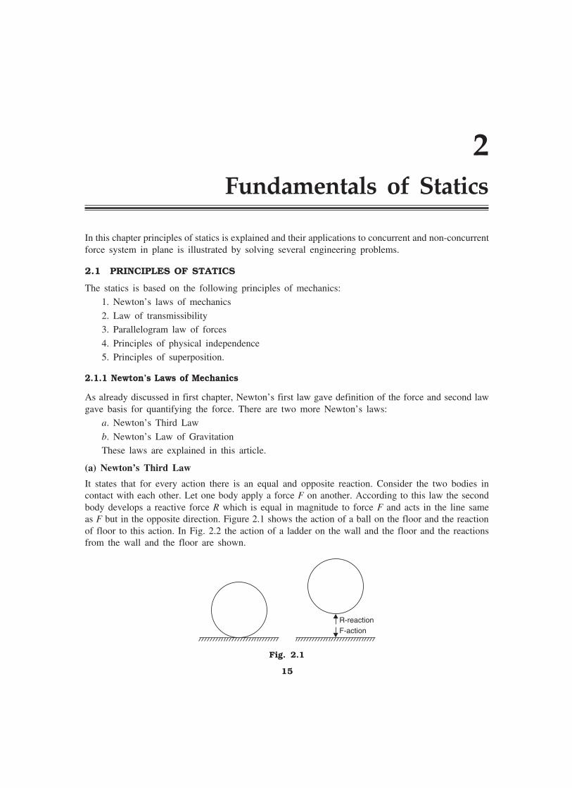
It states that for every action there is an equal and opposite reaction. Consider the two bodies incontact with each other. Let one body apply a force F on another. According to this law the secondbody develops a reactive force R which is equal in magnitude to force F and acts in the line sameas F but in the opposite direction. Figure 2.1 shows the action of a ball on the floor and the reactionof floor to this action. In Fig. 2.2 the action of a ladder on the wall and the floor and the reactionsfrom the wall and the floor are shown.
R-reactionF-action
Fig. 2.1
15

16 MECHANICS OF SOLIDS
R1
F1
R2
F2
Fig. 2.2
(b) Newton’s Law of Gravitation
It states that everybody attracts the other body. The force of attraction between any two bodies isdirectly proportional to their masses and inversely proportional to the square of the distance betweenthem. Thus the force of attraction between the bodies of mass m1 and mass m2 at distance ‘d’between them as shown in Fig. 2.3 is
F = G m m
d1 2
2...(2.1)
where G is the constant of proportionality and is known as constant of gravitation.
1m1
F 2m2
F
dd
Fig. 2.3
From eqn. 2.1,
G = Fd
m m
2
1 2
Hence unit of G = N m
kg kg
××
2
= Nm2/kg2
It has been proved by experiments that the value of G = 6.673 × 10⁻¹¹ Nm2/kg2. Thus if twobodies one of mass 10 kg and the other of 5 kg are at a distance of 1 m, they exert a force
F = 6 673 10 10 5
1
11
2
. × × ×−
= 33.365 × 10⁻¹⁰ N
on each other.
FUNDAMENTALS OF STATICS 17
Similarly 1 kg-mass on earth surface experiences a force of
F = 6 673 10 1 5 96504 10
6371 10
11 24
3 2
. .
( )
× × × ××
−
= 9.80665 N
Since, mass of earth = 5.96504 × 1024 kg
and radius of earth = 6371 × 103 m.This force of attraction is always directed towards the centre of earth.
In common usage the force exerted by a earth on a body is known as weight of the body. Thusweight of 1 kg-mass on/near earth surface is 9.80665 N, which is approximated as 9.81 N for allpractical problems. Compared to this force the force exerted by two bodies on each other is negligible.Thus in statics:
a. Weight of a body = mgb. Its direction is towards the centre of the earth, in other words, vertically downward.
c. The force of attraction between the other two objects on the earth is negligible.
2.1.2 Law of Transmissibility
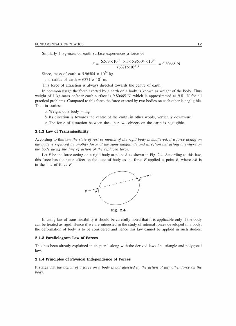
According to this law the state of rest or motion of the rigid body is unaltered, if a force acting onthe body is replaced by another force of the same magnitude and direction but acting anywhere onthe body along the line of action of the replaced force.
Let F be the force acting on a rigid body at point A as shown in Fig. 2.4. According to this law,this force has the same effect on the state of body as the force F applied at point B, where AB isin the line of force F.
A
B
F
F
Fig. 2.4
In using law of transmissibility it should be carefully noted that it is applicable only if the bodycan be treated as rigid. Hence if we are interested in the study of internal forces developed in a body,the deformation of body is to be considered and hence this law cannot be applied in such studies.
2.1.3 Parallelogram Law of Forces
This has been already explained in chapter 1 along with the derived laws i.e., triangle and polygonallaw.
2.1.4 Principles of Physical Independence of Forces
It states that the action of a force on a body is not affected by the action of any other force on thebody.
18 MECHANICS OF SOLIDS
2.1.5 Principles of Superposition of Forces
It states that the net effect of a system of forces on a body is same as the combined of individualforces acting on the body. Since a system of forces in equilibrium do not have any effect on a rigidbody this principle is stated in the following form also: ‘The effect of a given system of forces ona rigid body is not changed by adding or subtracting another system of forces in equilibrium.’
2.2 SYSTEM OF FORCES
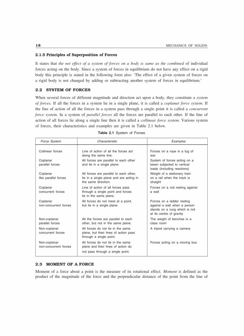
When several forces of different magnitude and direction act upon a body, they constitute a systemof forces. If all the forces in a system lie in a single plane, it is called a coplanar force system. Ifthe line of action of all the forces in a system pass through a single point it is called a concurrentforce system. In a system of parallel forces all the forces are parallel to each other. If the line ofaction of all forces lie along a single line then it is called a collinear force system. Various systemof forces, their characteristics and examples are given in Table 2.1 below.
Table 2.1 System of Forces
Force System Characteristic Examples
Collinear forces Line of action of all the forces act Forces on a rope in a tug ofalong the same line. war
Coplanar All forces are parallel to each other System of forces acting on aparallel forces and lie in a single plane. beam subjected to vertical
loads (including reactions)
Coplanar All forces are parallel to each other, Weight of a stationary trainlike parallel forces lie in a single plane and are acting in on a rail when the track is
the same direction. straight
Coplanar Line of action of all forces pass Forces on a rod resting againstconcurrent forces through a single point and forces a wall
lie in the same plane.
Coplanar All forces do not meet at a point, Forces on a ladder restingnon-concurrent forces but lie in a single plane. against a wall when a person
stands on a rung which is notat its centre of gravity
Non-coplanar All the forces are parallel to each The weight of benches in aparallel forces other, but not in the same plane. class room
Non-coplanar All forces do not lie in the same A tripod carrying a cameraconcurrent forces plane, but their lines of action pass
through a single point.
Non-coplanar All forces do not lie in the same Forces acting on a moving busnon-concurrent forces plane and their lines of action do
not pass through a single point.
2.3 MOMENT OF A FORCE
Moment of a force about a point is the measure of its rotational effect. Moment is defined as theproduct of the magnitude of the force and the perpendicular distance of the point from the line of

FUNDAMENTALS OF STATICS 19
action of the force. The point about which the moment is considered is called moment centre andthe perpendicular distance of the point from the line of action of the force is called moment arm.Referring to Fig. 2.5, if d1 is the perpendicular distance of point 1 from the line of action of forceF, the moment of F about point 1 is given by
M1 = F d1 ...(2.2)Similarly, moment about point 2 is given by
M2 = F d2 ...(2.3)If the moment centre 3 lies on the line of action of the force F, the moment arm is zero and
hence,M3 = F × 0 = 0 ...(2.4)
Thus, it may be noted that if a point lie on the line of action of a force, the moment of the forceabout that point is zero.
The moment of a force has got direction also. In Fig. 2.5 it may be notedthat M1 is clockwise and M2 is anticlockwise. To find the direction of themoment, imagine that the line of action of the force is connected to the pointby a rigid rod pinned at the point and is free to move around the point. Thedirection of the rotation indicates the direction of the moment.
If the force is taken in newton unit and the distance in millimetre, the unitof moment will be N-mm. Commonly used units of moment in engineering arekN-m, N-m, kN-mm and N-mm.
2.4 VARIGNON’S THEOREM
French mathematician Varignon (1654–1722) gave the following theorem which is also known asprinciple of moments:
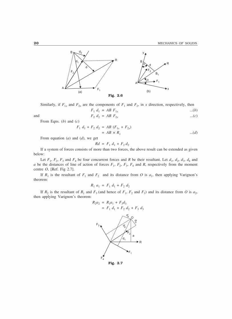
The algebraic sum of the moments of a system of coplanar forces about a moment centre in theirplane is equal to the moment of their resultant force about the same moment centre.
Proof: Referring to Fig. 2.6 let R be the resultant of forces F1 and F2 and B the moment centre.Let d, d1 and d2 be the moment arms of the forces, R, F1 and F2, respectively from the moment centreB. Then in this case, we have to prove that:
Rd = F1 d1 + F2 d2
Join AB and consider it as y axis and draw x axis at right angles to it at A [Fig. 2.6(b)]. Denotingby θ the angle that R makes with x axis and noting that the same angle is formed by perpendicularto R at B with AB1, we can write:
Rd = R × AB cosθ= AB × (R cosθ)
= AB × Rx ...(a)
where Rx denotes the component of R in x direction.
Fig. 2.5
F
x2
x3
1xd2
d1
20 MECHANICS OF SOLIDS
A
y
� F1
F2B1
x
RB
d�
(b)
R
F1
d2
d1
F2
B
A
(a)
d
Fig. 2.6
Similarly, if F1x and F2x are the components of F1 and F2, in x direction, respectively, thenF1 d1 = AB F1x ...(b)
and F2 d2 = AB F2x ...(c)From Eqns. (b) and (c)
F1 d1 + F2 d2 = AB (F1x + F2x)= AB × Rx ...(d)
From equation (a) and (d), we getRd = F1 d1 + F2 d2
If a system of forces consists of more than two forces, the above result can be extended as givenbelow:
Let F1, F2, F3 and F4 be four concurrent forces and R be their resultant. Let d1, d2, d3, d4 anda be the distances of line of action of forces F1, F2, F3, F4 and R, respectively from the momentcentre O, [Ref. Fig 2.7].
If R1 is the resultant of F1 and F2 and its distance from O is a1, then applying Varignon’stheorem:
R1 a1 = F1 d1 + F2 d2
If R2 is the resultant of R1 and F3 (and hence of F1, F2 and F3) and its distance from O is a2,then applying Varignon’s theorem:
R2a2 = R1a1 + F3d3
= F1 d1 + F2 d2 + F3 d3
F3
d2
d4
d3
O
F4
F1
F2
d1
R
a
Fig. 2.7
FUNDAMENTALS OF STATICS 21
Now considering R2 and F4, we can write:
Ra = R2 a2 + F4 d4
Since R is the resultant of R2 and F4 (i.e. F1, F2, F3 and F4).
∴ Ra = F1d1 + F2d2 + F3d3 + F4d4 ...(2.5)
Thus, the moment of the resultant of a number of forces about a moment centre is equal to thesum of the moments of its component forces about the same moment centre.
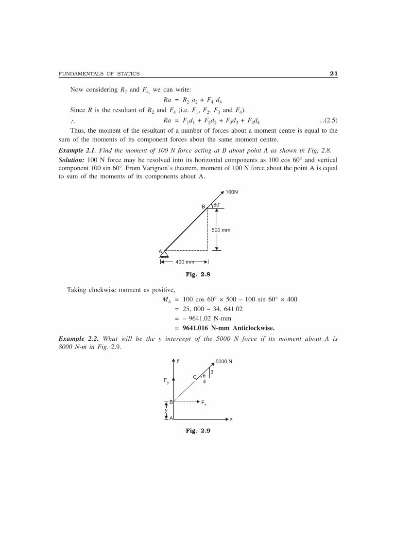
Example 2.1. Find the moment of 100 N force acting at B about point A as shown in Fig. 2.8.
Solution: 100 N force may be resolved into its horizontal components as 100 cos 60° and verticalcomponent 100 sin 60°. From Varignon’s theorem, moment of 100 N force about the point A is equalto sum of the moments of its components about A.
A
B
400 mm
500 mm
100N
60°
Fig. 2.8
Taking clockwise moment as positive,MA = 100 cos 60° × 500 – 100 sin 60° × 400
= 25, 000 – 34, 641.02= – 9641.02 N-mm
= 9641.016 N-mm Anticlockwise.
Example 2.2. What will be the y intercept of the 5000 N force if its moment about A is8000 N-m in Fig. 2.9.
y
Fy
�3
4C
5000 N
Fx
x
y
A
B
Fig. 2.9
22 MECHANICS OF SOLIDS
Solution: 5000 N force is shifted to a point B along its line of action (law of transmissibility) andit is resolved into its x and y components (Fx and Fy as shown in Fig. 2.9).
Fx = 5000 cos θ = =500045
4000× N
and Fy = 5000 sin θ = =500035
3000× N.
By Varignon's theorem, moment of 5000 N force about A is equal to moment of its componentforces about the same point.
8000 = 4000 × y + 3000 × 0
∴ y = 2 m.
2.5 COUPLE
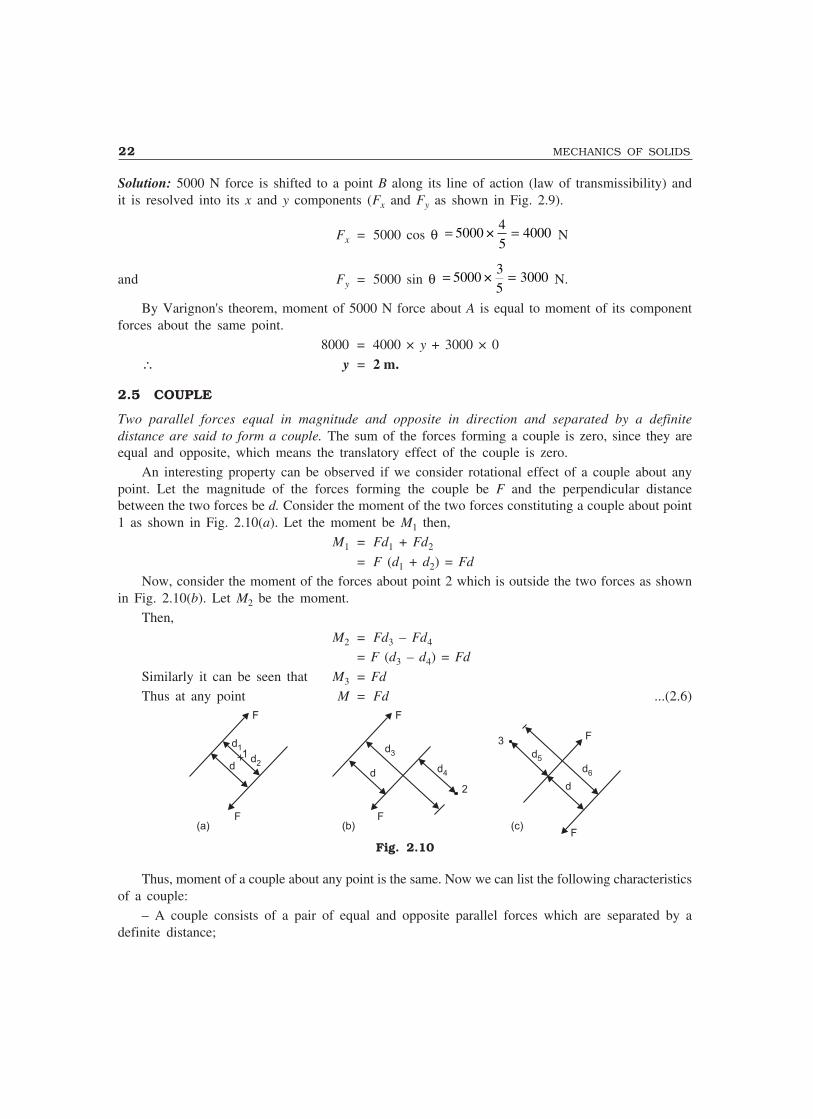
Two parallel forces equal in magnitude and opposite in direction and separated by a definitedistance are said to form a couple. The sum of the forces forming a couple is zero, since they areequal and opposite, which means the translatory effect of the couple is zero.
An interesting property can be observed if we consider rotational effect of a couple about anypoint. Let the magnitude of the forces forming the couple be F and the perpendicular distancebetween the two forces be d. Consider the moment of the two forces constituting a couple about point1 as shown in Fig. 2.10(a). Let the moment be M1 then,
M1 = Fd1 + Fd2
= F (d1 + d2) = Fd
Now, consider the moment of the forces about point 2 which is outside the two forces as shownin Fig. 2.10(b). Let M2 be the moment.
Then,
M2 = Fd3 – Fd4
= F (d3 – d4) = Fd
Similarly it can be seen that M3 = Fd
Thus at any point M = Fd ...(2.6)
dd
d
d1 d3 d5
d4 d6
d2
F F
F
F F
F
1
2
3
(a) (b) (c)
Fig. 2.10
Thus, moment of a couple about any point is the same. Now we can list the following characteristicsof a couple:
– A couple consists of a pair of equal and opposite parallel forces which are separated by adefinite distance;

FUNDAMENTALS OF STATICS 23
– The translatory effect of a couple on the body is zero;
– The rotational effect (moment) of a couple about any point is a constant and it is equal to theproduct of the magnitude of the forces and the perpendicular distance between the two forces.
Since the only effect of a couple is a moment and this moment is the same about any point, theeffect of a couple is unchanged if:
– The couple is rotated through any angle;
– The couple is shifted to any other position;– The couple is replaced by another pair of forces whose rotational effect is the same.
2.6 TRANSFER OF A FORCE TO PARALLEL POSITION
It will be advantageous to resolve a force acting at a point on a body into a force acting at some othersuitable point on the body and a couple. In Fig. 2.11(a) F is a force acting on a body at A.
A AA
d d
BB B
(a) (b) (c)
= =
F F
F F
F
M = Pd
Fig. 2.11
Now it can be shown that F at A may be resolved into force F at B and a couple of magnitudeM = F × d, where d is the perpendicular distance of B from the line of action of F through A.
By applying equal and opposite forces F at B the system of forces is not disturbed. Hence thesystem of forces in Fig. 2.11(b) is the same as the system given in Fig. 2.11(a). Now the originalforce F at A and the opposite force F at B form a couple of magnitude Fd. The system in Fig. 2.11(b)can be replaced by the system shown in Fig. 2.11(c). Thus, the given force F at A is replaced bya force F at B and a moment Fd.
2.7 COMPOSITION OF CONCURRENT COPLANAR FORCES
General ApproachIn chapter 1, composition of concurrent forces by graphical method and the analytical method
of composition of two force system has been discussed. In this article composition of concurrentcoplanar forces is explained by a general analytic method.
Analytical method consists in finding the components of given forces in two mutually perpendiculardirections and then combining them to get the resultant. Finding the component of a force is calledresolution of forces and is exactly the opposite to the process of composition of forces. Finding thecomponents of forces in two mutually perpendicularly directions is preferable. The following pointsassociated with the analytical method of finding rectangular components may be noted:
(i) Imagine that the arrow drawn to show force represents it to some scale
(ii) Travel from tail to head of the arrow in the directions of coordinates

24 MECHANICS OF SOLIDS
(iii) The direction of the travel gives the direction of component forces
(iv) From the triangle law of forces, the magnitude of the components can be calculated.
After finding the components of all the forces in the system in the two mutually perpendiculardirections, the component in each direction are algebraically added to get the two components. Thesetwo components, which are mutually perpendicular, are combined to get the resultant.
Let F1, F2, F3 and F4 shown in Fig. 2.12(a) be the system of four forces the resultant of whichis required.
Y
x
F1y
F4y
F4
F1xF4x
F1
F2
F2y F2x
F3x
F3y
F3
O
��
�
Fx
Fy
(b)
R
(a)
Fig. 2.12
The procedure to get the resultant is given below:Step 1: Find the components of all the forces in X and Y directions. Thus, F1x, F2x, F3x, F4x, F1y,
F2y, F3y, and F4y, are obtained.
Step 2: Find the algebraic sum of the component forces in X and Y directions.Σ Fx = F1x + F2x + F3x + F4x
Σ Fy = F1y + F2y + F3y + F4y
(Note: In the above case F2x, F3x, F3Y and F4Y have negative values.)
Step 3: Now the system of forces is equal to two mutually perpendicular forces, namely, ΣFx andΣFy as shown in Fig. 2.12(b). Since these two forces are perpendicular, the parallelogram of forcesbecomes a rectangle. Hence the resultant R is given by:
( ) ( )22x yR F F= Σ + Σ ...(2.7)
and its inclination to x axis is given by:
1
� ���y
x
F
F− Σ
= Σ ...(2.8)
Note: R cos α = ΣFx = Rx ...(2.9)
and R sin α = ΣFy = Ry ...(2.10)
i.e., ΣFx and ΣFy are the x and y components of the resultant.The procedure of finding the component of forces and then finding the resultant is illustrated
with examples 2.3 to 2.9.
FUNDAMENTALS OF STATICS 25
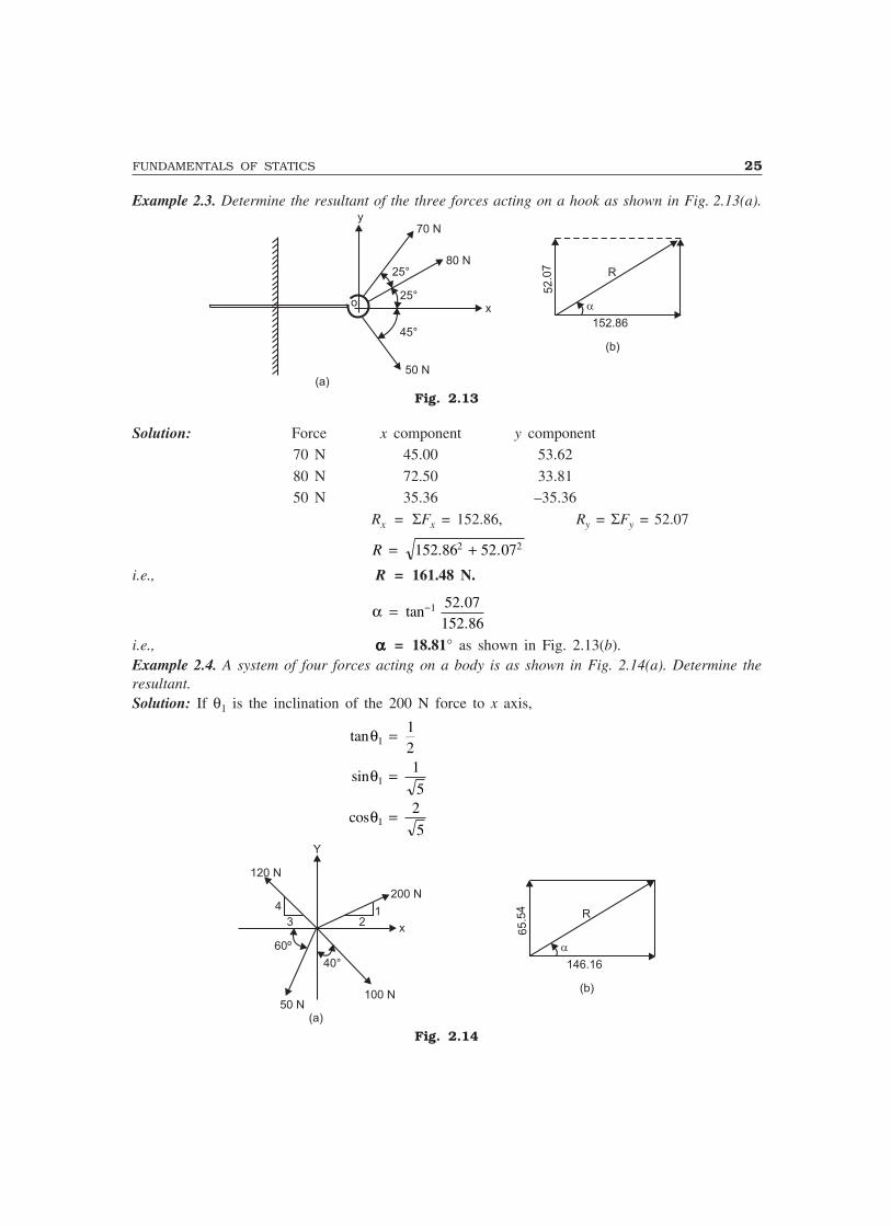
Example 2.3. Determine the resultant of the three forces acting on a hook as shown in Fig. 2.13(a).y
70 N
80 N
50 N
x
(a)
o
25°
25°
45°152.86
(b)
52.0
7 R
�
Fig. 2.13
Solution: Force x component y component70 N 45.00 53.62
80 N 72.50 33.8150 N 35.36 –35.36
Rx = ΣFx = 152.86, Ry = ΣFy = 52.07
R = +152 86 52 072 2. .
i.e., R = 161.48 N.
α = −tan..
1 52 07152 86
i.e., ααααα = 18.81° as shown in Fig. 2.13(b).Example 2.4. A system of four forces acting on a body is as shown in Fig. 2.14(a). Determine theresultant.Solution: If θ1 is the inclination of the 200 N force to x axis,
tanθ112
=
sinθ11
5=
cosθ12
5=
146.16
(b)
65.5
4 R
�
50 N100 N
200 N
Y
120 N
x
(a)
123
4
60º
40°
Fig. 2.14

26 MECHANICS OF SOLIDS
Similarly for the force 120 N,
tanθ243
= , sin θ245
= , cos θ235
=
Now, Rx = ΣFx = − −2002
5120
35
50× × cos 60° + 100 sin 40°
= 146.16 N.
Ry = ΣFy = + −2001
5120
45
50× × × sin 60° – 100 cos 40°
= 65.54 N
R = +146 16 65 542 2. . R = 160.18 N.
ααααα = tan.
.−1 65 54
146 16= 24.15° as shown in Fig. 2.14(b).
Example 2.5. A system of forces acting on a body resting on an inclined plane is as shown in Fig.2.15. Determine the resultant force if θ = 60° and if W = 1000 N; N = 500 N; F = 100 N; andT = 1200 N.
Horizon ta lθ°
Y
wT
X
F
N
Fig. 2.15
Solution: In this problem, note that selecting X and Y axes parallel to the plane and perpendicularto the plane is convenient.
Rx = ΣFx = T – F – W sin θ= 1200 – 100 – 1000 sin 60° = 233.97 N
Ry = ΣFy = N – W cos 60° = 500 – 1000 cos 60° = 0.
∴ Resultant is force of 233.97 N directed up the plane.
Example 2.6. Two forces acting on a body are 500 N and 1000 N as shown in Fig. 2.16(a).Determine the third force F such that the resultant of all the three forces is 1000 N directed at 45°to x axis.
Solution: Let the third force F make an angle θ with x axis.

FUNDAMENTALS OF STATICS 27
Y1000 N
R=1000 N
500 N
X30°
30°
45°
(a) (b)
F
225.9 N
�
408.91 N
Fig. 2.16
Then, R cos α = ΣFx
i.e., 1000 cos 45° = 500 cos 30° + 1000 sin 30° + F cos θ∴ F cos θ = –255.9
and R sin α = ΣFy
1000 sin 45° = 500 sin 30° + 1000 cos 30° + F sin θ∴ F sin α = – 408.91 N
∴ F = 225 9 408 912 2. .+i.e., F = 467.2 N.
θ = ��
��
−tan.
.1 408 91
255 9 = 61.08° as shown in Fig. 2.16.
Example 2.7. Three forces acting at a point are shown in Fig. 2.17. The direction of the 300 N forcesmay vary, but the angle between them is always 40°. Determine the value of θ for which the resultantof the three forces is directed parallel to b-b.
Solution: Let the x and y axes be as shown in Fig. 2.17. If the resultant is directed along the x axis,its component in y direction is zero.
i.e., 0 = ΣFy = 300 sin θ + 300 sin (40 + θ) – 500 sin 30°
∴ sin θ + sin (40 + θ) = 500 30
300sin °
= 0.8333
∴ sin θ + sin(40 + θ) = 0.8333
240
240
2sin × cos
+ +���
���
+ −���
���
θ θ θ θ= 0.8333
2 sin (20 + θ) × cos (20) = 0.8333
∴ θθθθθ = 6.35°
x
30°
b
30º
500 N
Y
300 N 300 N
�40°
b
Fig. 2.17
28 MECHANICS OF SOLIDS
2.8 EQUILIBRIANT OF A FORCE SYSTEM
We have seen that the resultant of a system of forces is a single force which will have the same effectas the system of forces. According to Newton’s second law of motion, the body starts moving withacceleration in the direction of the resultant force. If we apply a force equal and opposite to theresultant, the body should come to the equilibrium state. Such a force is called equilibriant. Thus anequilibriant of a system of forces may be defined as the force which brings the body to the state ofequilibrium and obviously, this forces is equal in magnitude, but opposite in the direction to theresultant.
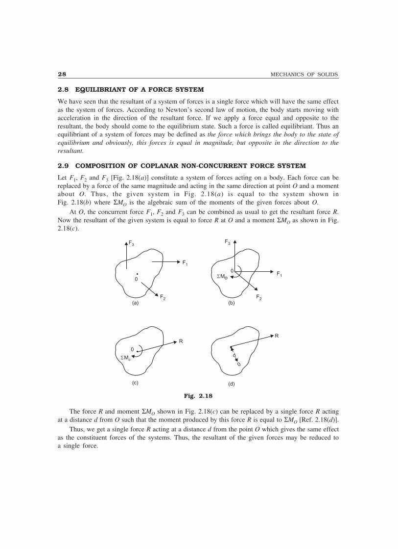
2.9 COMPOSITION OF COPLANAR NON-CONCURRENT FORCE SYSTEM
Let F1, F2 and F3 [Fig. 2.18(a)] constitute a system of forces acting on a body. Each force can bereplaced by a force of the same magnitude and acting in the same direction at point O and a momentabout O. Thus, the given system in Fig. 2.18(a) is equal to the system shown inFig. 2.18(b) where ΣMO is the algebraic sum of the moments of the given forces about O.
At O, the concurrent force F1, F2 and F3 can be combined as usual to get the resultant force R.Now the resultant of the given system is equal to force R at O and a moment ΣMO as shown in Fig.2.18(c).
(a) (b)
F3F3
F1
F1
F2 F2
0
0�Mo
�Mo
(c) (d)
RR
0
0
d
Fig. 2.18
The force R and moment ΣMO shown in Fig. 2.18(c) can be replaced by a single force R actingat a distance d from O such that the moment produced by this force R is equal to ΣMO [Ref. 2.18(d)].
Thus, we get a single force R acting at a distance d from the point O which gives the same effectas the constituent forces of the systems. Thus, the resultant of the given forces may be reduced toa single force.
FUNDAMENTALS OF STATICS 29
Mathematically,
R F FF
F
x y
y
x
= +
=
�
�
( ) ( )
tan
Σ ΣΣΣ
2 2
α...(2.11)
d = Σ M
Ro
where, ΣFx – algebraic sum of the components of all forces in x direction
ΣFy – algebraic sum of the components of all forces in y direction
α – inclination of the resultant R to x direction
ΣMO – algebraic sum of the moments of all the forces about point O
d – is distance of the resultant R from the point O.
Note: R is marked at distance d such that it produces the same direction of moment about point O as ΣMO.
Sometimes the values of ΣFx and ΣFy may come out to be zero, but ΣMO may exist. This meansthat the resultant of the system gets reduced to a pure couple.
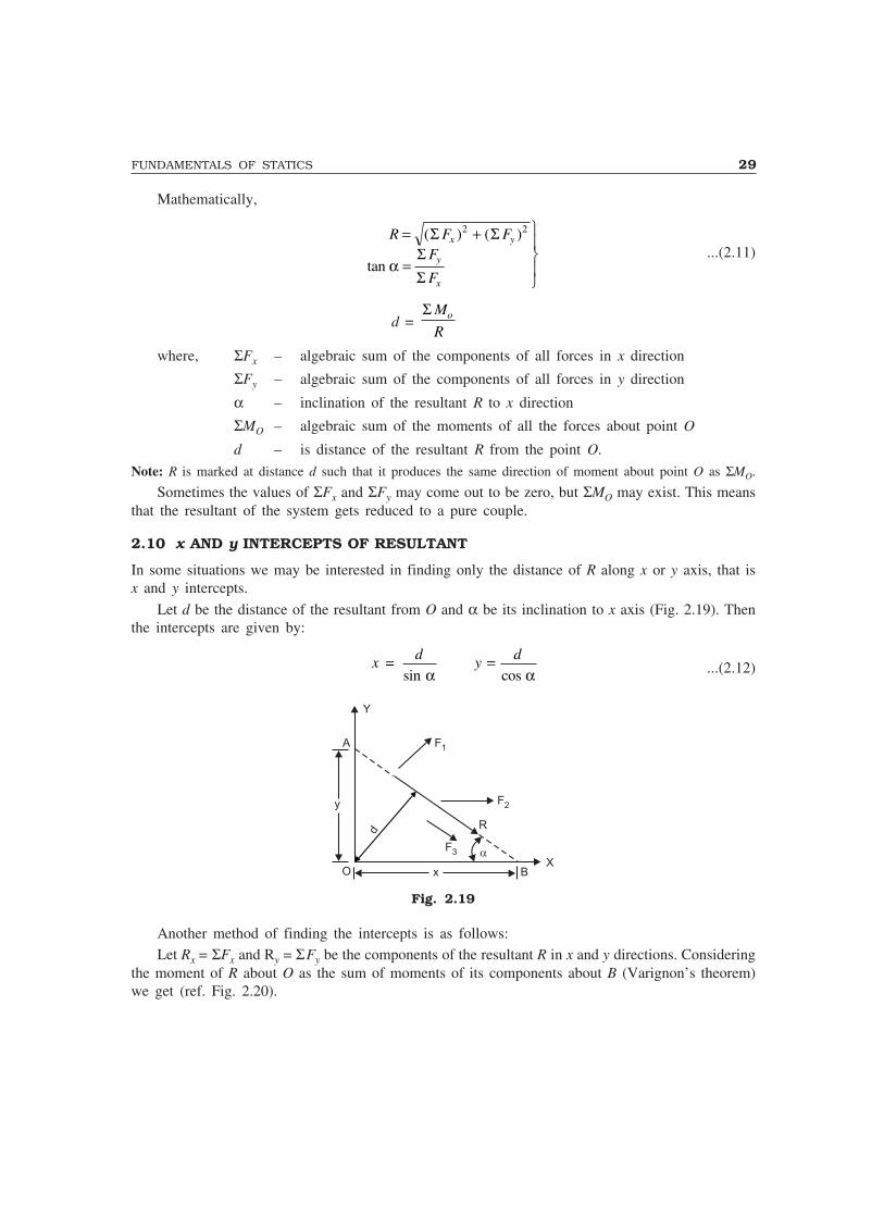
2.10 x AND y INTERCEPTS OF RESULTANT
In some situations we may be interested in finding only the distance of R along x or y axis, that isx and y intercepts.
Let d be the distance of the resultant from O and α be its inclination to x axis (Fig. 2.19). Thenthe intercepts are given by:
x d y d=sin α α
=cos ...(2.12)
d
Y
XO
y
x B
F3
F2
F1
�
A
R
Fig. 2.19
Another method of finding the intercepts is as follows:Let Rx = ΣFx and Ry = ΣFy be the components of the resultant R in x and y directions. Considering
the moment of R about O as the sum of moments of its components about B (Varignon’s theorem)we get (ref. Fig. 2.20).

30 MECHANICS OF SOLIDS
Rd = ΣMO
Rx × 0 + Ry x = ΣMO
∴ x = Σ ΣΣ
M
R
M
Fo
y
o
y
= ...(2.13)
Y
R x
R y
O
x
x
B
A
R
Fig. 2.20
Similarly, resolving the resultant into its components at A, it can be shown that:
y = Σ Σ
ΣM
R
M
Fo
x
o
x
= ...(2.14)
Example 2.8. A system of loads acting on a beam is shown in Fig. 2.21(a). Determine the resultantof the loads.
Solution: Taking horizontal direction towards left as x axis and the vertical downward direction asy axis.
ΣFx = 20 cos 60° = 10 kNΣFy = 20 + 30 + 20 sin 60° = 67.3205
BA
20 kN 30 kN
x
1 .5 m 1 .5 m 3 .0 m 2 .0 m
α 60°
R 20 kN
α
Σx
R Σy
d
(a) (b)Fig. 2.21
∴ R = Σ Σx y� � � �2 2+ = 10 67 32052 2+ ( . )
i.e., R = 68.0592 kN.
tan α = ΣΣ
F
Fy
x = 6.7321
∴ ααααα = 81.55°.

FUNDAMENTALS OF STATICS 31
Now taking moment about A,
ΣMA = 20 × 1.5 + 30 × 3.0 + 20 sin 60° × 6= 223.9231 kN-m
∴ The distance of the resultant from point O is given by:
dMR
A= = =Σ 223 923168 0592
3 290.
.. m
∴ xd= =
°sin.
sin .α3 290
81 55
x = 3.326 m.The value of x intercept may be obtained using Eqn. 2.13 also. Thus,
x = Σ Σ
ΣM
R
M
Fy y
0 0 223 9231
67 3205= = .
. = 3.326 m.
Example 2.9. Find the resultant of the force system shown in Fig. 2.22(a) acting on a lamina ofequilateral triangular shape.
Solution: ΣFx = 80 – 100 cos 60° – 120 cos 30° = – 73.92 N(Negative sign shows that Rx acts from right to left)
80 N
B 80 N
100 N
60°
x
R
(a)
(b)
C
120 N
100 mm
30°A
R
�
�Fx
�Fy
y
x
Fig. 2.22
Rx = 73.92←
NΣFy = 80 + 120 sin 30° – 100 sin 60°
Ry = 53.40 N
∴ R = +73 92 53 402 2. .
R = 91.19 N
tan α = ΣΣ
F
Fy
x =
53
73 92
.40
.
ααααα = 35.84°Let x be the distance from A at which the resultant cuts AC. Then taking A as moment centre,
53.40x = 80 × 100 sin 60° + 80 × 50 + 120 sin 30° × 100 x = 317.008 mm to the right of A as shown in Fig. 2.22(a).
32 MECHANICS OF SOLIDS
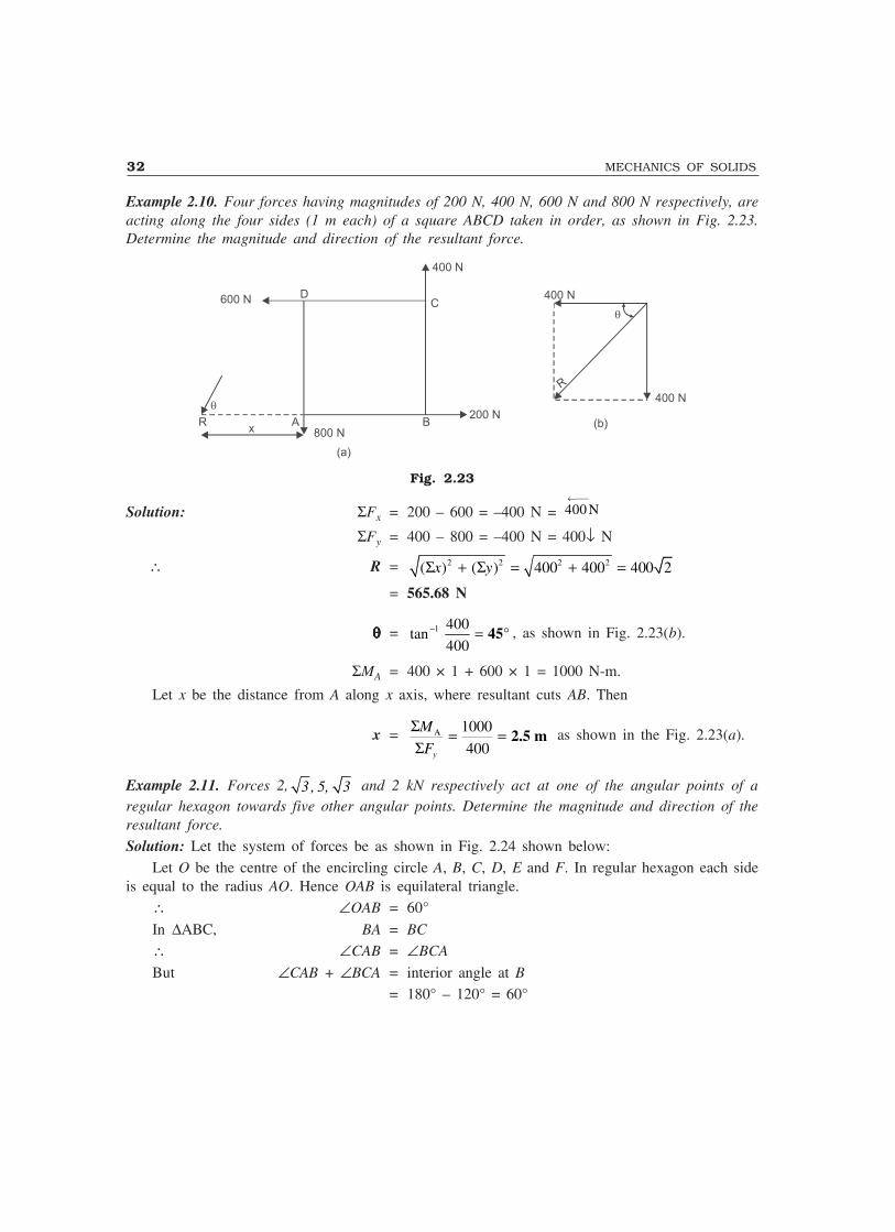
Example 2.10. Four forces having magnitudes of 200 N, 400 N, 600 N and 800 N respectively, areacting along the four sides (1 m each) of a square ABCD taken in order, as shown in Fig. 2.23.Determine the magnitude and direction of the resultant force.
xR
800 NA B
200 N
600 N DC
400 N
400 N
400 NR
�
�
(a)
(b)
Fig. 2.23
Solution: ΣFx = 200 – 600 = –400 N = 400 N←−−−
ΣFy = 400 – 800 = –400 N = 400↓ N
∴ R = 2 2 2 2( ) ( ) 400 400 400 2Σ + Σ = + =x y
= 565.68 N
θθθθθ = 1 400tan
400− = 45° , as shown in Fig. 2.23(b).
ΣMA = 400 × 1 + 600 × 1 = 1000 N-m.
Let x be the distance from A along x axis, where resultant cuts AB. Then
x = A 1000
400y
M
F
Σ = =Σ
2.5 m as shown in the Fig. 2.23(a).
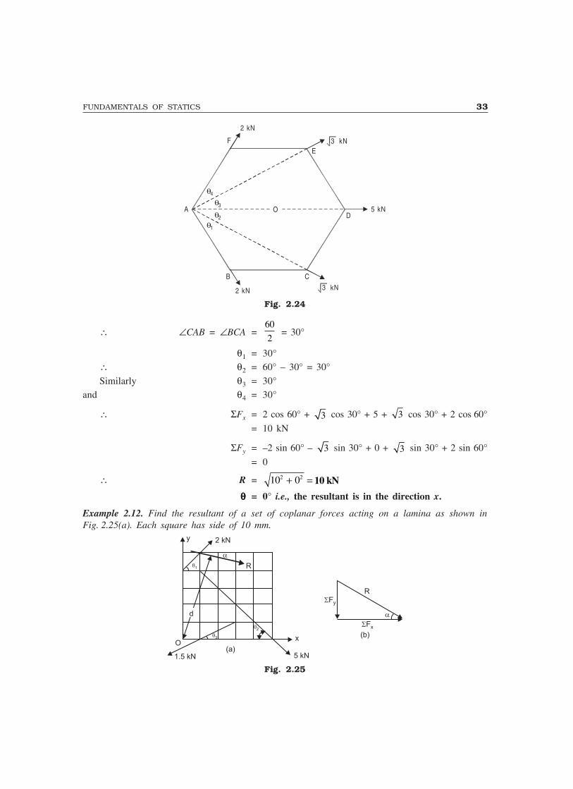
Example 2.11. Forces 2, 3 , 5, 3 and 2 kN respectively act at one of the angular points of aregular hexagon towards five other angular points. Determine the magnitude and direction of theresultant force.
Solution: Let the system of forces be as shown in Fig. 2.24 shown below:Let O be the centre of the encircling circle A, B, C, D, E and F. In regular hexagon each side
is equal to the radius AO. Hence OAB is equilateral triangle.∴ ∠OAB = 60°
In ∆ABC, BA = BC
∴ ∠CAB = ∠BCA
But ∠CAB + ∠BCA = interior angle at B
= 180° – 120° = 60°
FUNDAMENTALS OF STATICS 33
θ4
θ3
θ2θ1
OD
5 kN
E
2 kN
F
A
B C
2 kN 3 kN
3 kN
Fig. 2.24
∴ ∠CAB = ∠BCA =60
2 = 30°
θ1 = 30°∴ θ2 = 60° – 30° = 30°
Similarly θ3 = 30°and θ4 = 30°
∴ ΣFx = 2 cos 60° + 3 cos 30° + 5 + 3 cos 30° + 2 cos 60°
= 10 kN
ΣFy = –2 sin 60° – 3 sin 30° + 0 + 3 sin 30° + 2 sin 60°
= 0
∴ R = 2 210 0+ = 10 kN
θθθθθ = 0° i.e., the resultant is in the direction x.
Example 2.12. Find the resultant of a set of coplanar forces acting on a lamina as shown inFig. 2.25(a). Each square has side of 10 mm.
y
�2
�3
�1
d
1.5 kN 5 kN
x
2 kN
O
R
Fy
R
(a)
(b)
Fx
Fig. 2.25
34 MECHANICS OF SOLIDS
Solution: If θ1, θ2 and θ3 are the slopes of the forces 2 kN, 5 kN and 1.5 kN forces with respectto x axis, then
tan θ1 = 10
10 = 1 ∴ θ1 = 45°
tan θ2 = 30
40∴ θ2 = 36.87°
tan θ3 = 10
20∴ θ3 = 26.565
Rx = xFΣ = 2 cos 45° + 5 cos 36.87° – 1.5 cos 26.565° = 4.072 kN
R y= ΣFy = 2 sin 45° – 5 sin 36.87° – 1.5 sin 26.565° = 2.26 kN
R = ( ) ( )Σ ΣF Fx y2 2+ = 4.66 kN.
tan.
.α = 2 26
4 072
∴ ααααα = 28.99°.Distance d of the resultant from O is given by
Rd = ΣMO
4 66 2 45 30 5 36 87 50 1 5 26 565 10. cos sin . . sin .d = × ° × + × ° × + × ° ×= 199.13
d = 42.77 mm as shown in Fig. 2.25(a).Note: To find moment of forces about O, 2 kN force is resolved at it’s intersection with y axis and5 kN and 1.5 kN forces are resolved at their intersection with x axis, and then Varignon theorem is used.
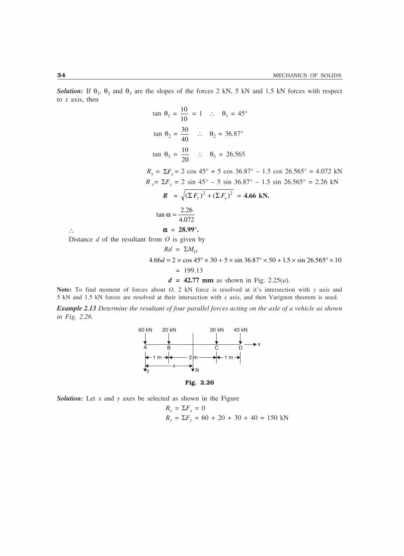
Example 2.13 Determine the resultant of four parallel forces acting on the axle of a vehicle as shownin Fig. 2.26.
A B C D
1 m1 m 2 m2 m 1 m1 m
xx
60 kN 20 kN 30 kN 40 kN
y R
x
Fig. 2.26
Solution: Let x and y axes be selected as shown in the FigureRx = ΣFx = 0Ry = ΣFy = 60 + 20 + 30 + 40 = 150 kN
FUNDAMENTALS OF STATICS 35
∴ R = 0 1502 2+ = 150 kN
Taking clockwise moment as +ve,ΣMA = 60 × 0 + 20 × 1 + 30 × 3 + 40 × 4
= 270 kN-m∴ Distance of resultant from A
x = 270
150 = 1.8 m as shown in the figure.
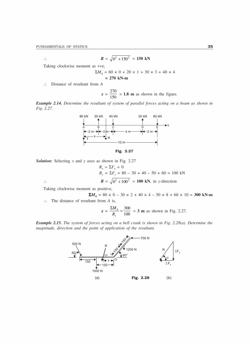
Example 2.14. Determine the resultant of system of parallel forces acting on a beam as shown inFig. 2.27.
80 kN 30 kN 40 kN 50 kN 60 kN
x
2 m2 m 2 m2 m 4 m4 m 2 m2 m
10 m10 m
xx
A B C D E
y R
Fig. 2.27
Solution: Selecting x and y axes as shown in Fig. 2.27
Rx = ΣFx = 0Ry = ΣFy = 80 – 30 + 40 – 50 + 60 = 100 kN
∴ R = 0 1002 2+ = 100 kN, in y-direction
Taking clockwise moment as positive,
ΣΣΣΣΣMA = 80 × 0 – 30 × 2 + 40 × 4 – 50 × 8 + 60 × 10 = 300 kN-m∴ The distance of resultant from A is,
x = ΣM
RA
y
= 300
100 = 3 m as shown in Fig. 2.27.
Example 2.15. The system of forces acting on a bell crank is shown in Fig. 2.28(a). Determine themagnitude, direction and the point of application of the resultant.
700 N
1000 N
60°
1200 N
500 N
60°
R
150150
150
150
x O
Fx
R Fy
(a) Fig. 2.28 (b)

36 MECHANICS OF SOLIDS
Solution: Rx = ΣFx = 500 cos 60° – 700 = – 450 N = 450 N (from right to left)
Ry = ΣFy = – 1200 – 1000 – 500 sin 60° = – 2633.01 N= 2633.01 N (downward)
R = 450 2633 012 2+ ( . )
R = 2671.19 N.
tan.α = 2633 01
450ααααα = 80.30°, as shown in Fig. 2.28(b).
Let the point of application of the resultant be at a distance x from the point O along thehorizontal arm. Then,
x × 2633.01 = 500 sin 60° × 300 + 1000 × 150
– 1200 × 150 cos 60° + 700 × 300 sin 60°x = 141.195 mm, as shown in Fig. 2.28(a).
Example 2.16. Various forces to be considered for the stability analysis of a dam are shown in theFig. 2.29. The dam is safe if the resultant force passes through middle third of the base. Verifywhether the dam is safe.
Solution: Rx = ΣFx = 500 kN
Ry = ΣFy = + 1120 – 120 + 420 = 1420 kN= 1420 kN (downward)
Let x be the distance from O where the resultant cuts the base.
xO
7 m
y
5 m
4m
420 kN
2m500 kN
120 kN
1120 kN
4 m
Fig. 2.29
Then xΣFy = ΣMO
x × 1420 = 500 × 4 + 1120 × 2 – 120 × 4 + 420 × 5
∴ x = 4.126 m
The resultant passes through the middle third of the base i.e., between 73
m, and 273
× m.
Hence, the dam is safe.
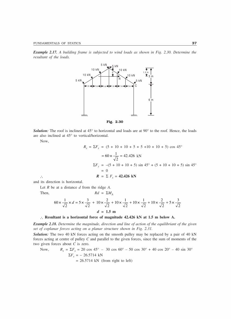
FUNDAMENTALS OF STATICS 37
Example 2.17. A building frame is subjected to wind loads as shown in Fig. 2.30. Determine theresultant of the loads.
1 m 1 m 1 m 1 m 1 m 1 m
5 kN
10 kN
10 kN
5 kN 5 kN10 kN
10 kN
5 kN
C
6 m
3 md 1 .5 m
R
Fig. 2.30
Solution: The roof is inclined at 45° to horizontal and loads are at 90° to the roof. Hence, the loadsare also inclined at 45° to vertical/horizontal.
Now,
Rx = ΣFx = (5 + 10 + 10 + 5 + 5 +10 + 10 + 5) cos 45°
= =60 12
42 426× . kN
ΣFy = –(5 + 10 + 10 + 5) sin 45° + (5 + 10 + 10 + 5) sin 45°
= 0
∴ R = Σ Fx = 42.426 kNand its direction is horizontal.
Let R be at a distance d from the ridge A.Then, Rd = ΣMA
601
25
3
210
2
210
1
210
1
210
2
25
3
2× × × × × × × ×d = + + + + +
d = 1.5 m
∴ Resultant is a horizontal force of magnitude 42.426 kN at 1.5 m below A.
Example 2.18. Determine the magnitude, direction and line of action of the equilibriant of the givenset of coplanar forces acting on a planar structure shown in Fig. 2.31.
Solution: The two 40 kN forces acting on the smooth pulley may be replaced by a pair of 40 kNforces acting at centre of pulley C and parallel to the given forces, since the sum of moments of thetwo given forces about C is zero.
Now, Rx = ΣFx = 20 cos 45° – 30 cos 60° – 50 cos 30° + 40 cos 20° – 40 sin 30°
ΣFx = – 26.5714 kN = 26.5714 kN (from right to left)
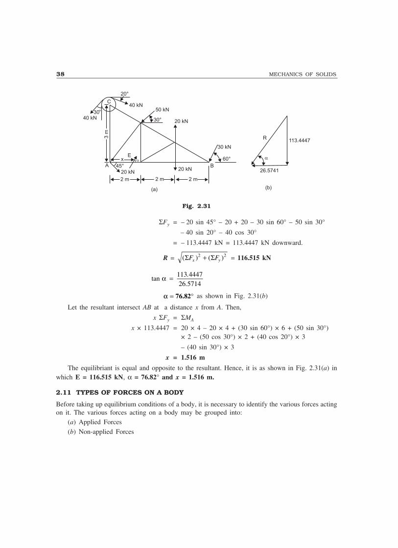
38 MECHANICS OF SOLIDS
C3
m
20°
30°
60°
30 kN
B20 kN
20 kN
40 kN
A
20 kN45°
xE
2 m 2 m 2 m
50 kN
30°
R113.4447
26.5741
(a) (b)
40 kN
Fig. 2.31
ΣFy = – 20 sin 45° – 20 + 20 – 30 sin 60° – 50 sin 30°
– 40 sin 20° – 40 cos 30°
= – 113.4447 kN = 113.4447 kN downward.
R = ( ) ( )Σ ΣF Fx y2 2+ = 116.515 kN
tan..
α = 113 444726 5714
α = °76.82 as shown in Fig. 2.31(b)
Let the resultant intersect AB at a distance x from A. Then,
x ΣFy = ΣMA
x × 113.4447 = 20 × 4 – 20 × 4 + (30 sin 60°) × 6 + (50 sin 30°)× 2 – (50 cos 30°) × 2 + (40 cos 20°) × 3
– (40 sin 30°) × 3
x = 1.516 m
The equilibriant is equal and opposite to the resultant. Hence, it is as shown in Fig. 2.31(a) inwhich E = 116.515 kN, α = 76.82° and x = 1.516 m.
2.11 TYPES OF FORCES ON A BODY
Before taking up equilibrium conditions of a body, it is necessary to identify the various forces actingon it. The various forces acting on a body may be grouped into:
(a) Applied Forces
(b) Non-applied Forces

FUNDAMENTALS OF STATICS 39
(a) Applied ForcesThese are the forces applied externally to a body. Each of the forces is having contact with the body.Depending upon type of their contact with the body, the applied forces may be classified as:
(i) Point Force(ii) Distributed Forces
(i) Point Force: It is the one which has got contact with the body at a point. Practically thereis no force which will have contact with the body at a single point. However, when the contact areais small compared to the other dimensions in the problem, for simplicity of calculation the force maybe considered as a point load. If a person stands on a ladder, his weight be taken as an applied pointload [Fig. 1.2]. Characteristics of such forces are already explained in Art. 1.1.
(ii) Distributed Forces: Distributed forces may act over a line, a surface or a volume.Correspondingly they are known as linear, surface and body forces.
Linear Force: A linear force is one that acts along a line on the body. It is usually representedwith abscissa representing the position on the body and ordinate representing the magnitude of theload. An example of this force is a beam subjected to uniformly distributed/uniformly varying orgeneral load. The force ‘dF’ at any small length ‘ds’ is given by
dF = w ds
Surface Force: A force acting on the surface of a body is known as surface force. The hydrostaticpressure acting on a Dam is an example of surface force. The force dF acting on any area dA is givenby
dF = p dA
where ‘p’ is the intensity of force per unit area.
Body Force: A body force is the force exerted from each and every particle of the mass of thebody. Example of this type of force is the weight of a block acting on the body under consideration.The body force dF of volume dV is given by
dF = γ dV
where γ is the force per unit volume.
(b) Non-applied Forces
There are two types of non-applied forces: (a) Self weight and (b) Reactions.
Self weight: Everybody subjected to gravitational acceleration and hence has got a selfweight.W = mg
where m is mass of the body and g is gravitational acceleration (9.81 m/sec2 near the earth surface)
Selfweight always acts in vertically downward direction. When analysing equilibrium conditionsof a body, selfweight is treated as acting through the centre of gravity of the body. If selfweight isvery small, it may be neglected.
Reactions: These are self-adjusting forces developed by the other bodies which come in contactwith the body under consideration. According to Newton’s third law of motion, the reactions areequal and opposite to the actions. The reactions adjust themselves to bring the body to equilibrium.

40 MECHANICS OF SOLIDS
If the surface of contact is smooth, the direction of the reaction is normal to the surface ofcontact. If the surface of contact is not smooth, apart from normal reaction, there will be frictionalreaction also. Hence the resultant reaction will not be normal to the surface of contact.
2.12 FREE BODY DIAGRAM
In many problems, it is essential to isolate the body under consideration from the other bodies incontact and draw all the forces acting on the body. For this, first the body is drawn and then appliedforces, selfweight and the reactions at the points of contact with other bodies are drawn. Such adiagram of the body in which the body under consideration is freed from all the contact surfaces andshows all the forces acting on it (including reactions at contact surfaces), is called aFree Body Diagram (FBD). Free Body Diagrams (FBD) are shown for few typical cases inTable 2.2.
Table 2.2 Free Body Diagrams (FBD) for a Few Typical Cases
Reacting Bodies FBD required for FBD
R 1
R 2
P
G
W600 N
Sm
ooth
Sm
ooth
Sm ooth
P
600 N
Ball
Ba ll
Ladder
B lock weigh ing 600 N
600 N
400 N
W
W
R
T
R
600 N
T
R
2.13 EQUILIBRIUM OF BODIES
A body is said to be in equilibrium when it is at rest or has uniform motion. According to Newton’slaw of motion, it means the resultant of all the forces acting on a body in equilibrium is zero. Theresultant of coplanar system of forces acting on a body is zero when—
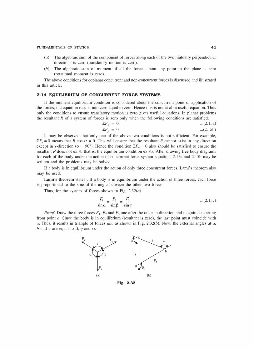
FUNDAMENTALS OF STATICS 41
(a) The algebraic sum of the component of forces along each of the two mutually perpendiculardirections is zero (translatory motion is zero).
(b) The algebraic sum of moment of all the forces about any point in the plane is zero(rotational moment is zero).
The above conditions for coplanar concurrent and non-concurrent forces is discussed and illustratedin this article.
2.14 EQUILIBRIUM OF CONCURRENT FORCE SYSTEMS
If the moment equilibrium condition is considered about the concurrent point of application ofthe forces, the equation results into zero equal to zero. Hence this is not at all a useful equation. Thusonly the conditions to ensure translatory motion is zero gives useful equations. In planar problemsthe resultant R of a system of forces is zero only when the following conditions are satisfied.
ΣFx = 0 ...(2.15a)ΣFy = 0 ...(2.15b)
It may be observed that only one of the above two conditions is not sufficient. For example,ΣFx = 0 means that R cos α = 0. This will ensure that the resultant R cannot exist in any directionexcept in y-direction (α = 90°). Hence the condition ΣFy = 0 also should be satisfied to ensure theresultant R does not exist, that is, the equilibrium condition exists. After drawing free body diagramsfor each of the body under the action of concurrent force system equations 2.15a and 2.15b may bewritten and the problems may be solved.
If a body is in equilibrium under the action of only three concurrent forces, Lami’s theorem alsomay be used.
Lami’s theorem states : If a body is in equilibrium under the action of three forces, each forceis proportional to the sine of the angle between the other two forces.
Thus, for the system of forces shown in Fig. 2.32(a).
31 2
sin� ���� ��� �
FF F= = ...(2.15c)
Proof: Draw the three forces F1, F2 and F3 one after the other in direction and magnitude startingfrom point a. Since the body is in equilibrium (resultant is zero), the last point must coincide witha. Thus, it results in triangle of forces abc as shown in Fig. 2.32(b). Now, the external angles at a,b and c are equal to β, γ and α.
F2 F2F1
F1
F3
F3
� �
�
�
(a) (b)
c
a
b
Fig. 2.32
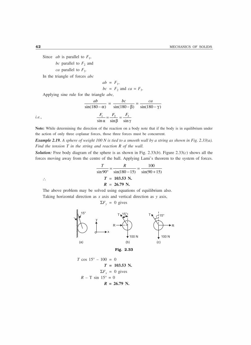
42 MECHANICS OF SOLIDS
Since ab is parallel to F1,
bc parallel to F2 and
ca parallel to F3.
In the triangle of forces abc
ab = F1,
bc = F2 and ca = F3.Applying sine rule for the triangle abc,
ab bc ca
sin( ) sin( ) sin( )180 180 180−=
−=
−α β γ
i.e., 31 2
sin� ���� ��� �
FF F= =
Note: While determining the direction of the reaction on a body note that if the body is in equilibrium under
the action of only three coplanar forces, those three forces must be concurrent.
Example 2.19. A sphere of weight 100 N is tied to a smooth wall by a string as shown in Fig. 2.33(a).Find the tension T in the string and reaction R of the wall.
Solution: Free body diagram of the sphere is as shown in Fig. 2.33(b). Figure 2.33(c) shows all theforces moving away from the centre of the ball. Applying Lami’s theorem to the system of forces.
T R
sin sin( ) sin( )90 180 15
100
90 15°=
−=
+
∴ T = 103.53 N.R = 26.79 N.
The above problem may be solved using equations of equilibrium also.
Taking horizontal direction as x axis and vertical direction as y axis,ΣFy = 0 gives
(a) (b) (c)
15°
y
x
R R
T T15°
100 N 100 N
15°
Fig. 2.33
T cos 15° – 100 = 0T = 103.53 N.
ΣFx = 0 givesR – T sin 15° = 0
R = 26.79 N.
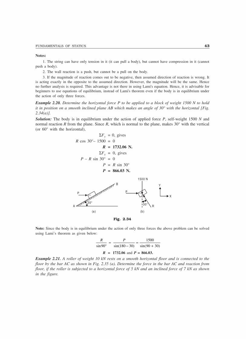
FUNDAMENTALS OF STATICS 43
Notes:
1. The string can have only tension in it (it can pull a body), but cannot have compression in it (cannotpush a body).
2. The wall reaction is a push, but cannot be a pull on the body.
3. If the magnitude of reaction comes out to be negative, then assumed direction of reaction is wrong. Itis acting exactly in the opposite to the assumed direction. However, the magnitude will be the same. Henceno further analysis is required. This advantage is not there in using Lami's equation. Hence, it is advisable forbeginners to use equations of equilibrium, instead of Lami's theorem even if the body is in equilibrium underthe action of only three forces.
Example 2.20. Determine the horizontal force P to be applied to a block of weight 1500 N to holdit in position on a smooth inclined plane AB which makes an angle of 30° with the horizontal [Fig.2.34(a)].
Solution: The body is in equilibrium under the action of applied force P, self-weight 1500 N andnormal reaction R from the plane. Since R, which is normal to the plane, makes 30° with the vertical(or 60° with the horizontal),
ΣFy = 0, gives
R cos 30°– 1500 = 0R = 1732.06 N.
ΣFx = 0, givesP – R sin 30° = 0
P = R sin 30°P = 866.03 N.
30°A
(a) (b )
B
P
1500 N
30° R
Y
XP
Fig. 2.34
Note: Since the body is in equilibrium under the action of only three forces the above problem can be solvedusing Lami’s theorem as given below:
R P
sin sin( ) sin( )90 180 30
1500
90 30°=
−=
+
R = 1732.06 and P = 866.03.
Example 2.21. A roller of weight 10 kN rests on a smooth horizontal floor and is connected to thefloor by the bar AC as shown in Fig. 2.35 (a). Determine the force in the bar AC and reaction fromfloor, if the roller is subjected to a horizontal force of 5 kN and an inclined force of 7 kN as shownin the figure.

44 MECHANICS OF SOLIDS
Solution: A bar can develop a tensile force or a compressive force. Let the force developed be acompressive force S (push on the cylinder). Free Body Diagram of the cylinder is as shown inFig. 2.35(b).
(a) (b)
R
7 kN 7 kN
5 kN 5 kN45°45°
A 30°
C
10 kN
S
30°
Fig. 2.35
Since there are more than three forces in the system, Lami’s equations cannot be applied.Consider the components in horizontal and vertical directions.
ΣH = 0S cos 30° + 5 – 7 cos 45° = 0
7cos 45 5–
cos 30
° −= =
°0.058 kNS
Since the value of S is negative the force exerted by the bar is not a push, but it is pull(tensile force in bar) of magnitude 0.058 kN.
ΣV = 0
R – 10 – 7 sin 45° + S sin 30° = 0
R = 10 + 7 sin 45° – S sin 30°
= 10 + 7 sin 45° – (– 0.058) sin 30°
R = 14.979 kN.
Example 2.22. A cord ACB 5 m long is attached at points A and B to two vertical walls 3 m apartas shown in Fig. 2.36(a). A pully C of negligible radius carries a suspended load of 200 N and isfree to roll without friction along the cord. Determine the position of equilibrium, as defined by thedistance X, that the pulley will assume and also the tensile force in the cord.
Solution: The pulley C is in equilibrium under the action of tensile forces in CA and CB and verticaldownward load 200 N. The tensile forces in segment CA and CB are the same since the pulley isfrictionless. Now consider the equilibrium of pulley C shown in Fig. 2.36(b).
ΣH = 0
T cos θ1 – T cos θ2 = 0
∴ θ1 = θ2, say, equal to θNow, let BC be extended to D.
∆CFD = ∆CFA
∴ CD = AC
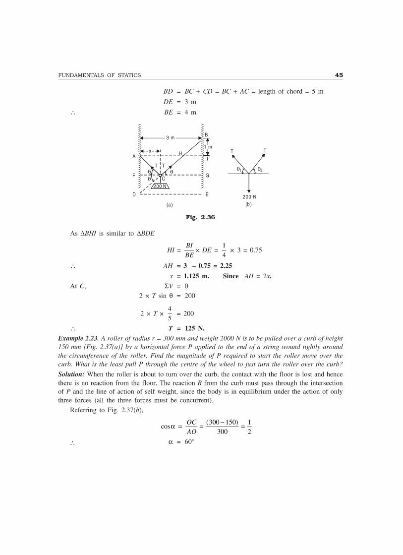
FUNDAMENTALS OF STATICS 45
BD = BC + CD = BC + AC = length of chord = 5 m
DE = 3 m
∴ BE = 4 m
B
(a) (b )
3 m
D
F
A I
G
E
1 m
200 N
x H
T Tθθ
θ
θ2
T
θ1
T
200 N
C
Fig. 2.36
As ∆BHI is similar to ∆BDE
HI = BI
BE× DE =
1
4 × 3 = 0.75
∴ AH = 3 – 0.75 = 2.25
x = 1.125 m. Since AH = 2x.At C, ΣV = 0
2 × T sin θ = 200
2 × T × 4
5= 200
∴ T = 125 N.Example 2.23. A roller of radius r = 300 mm and weight 2000 N is to be pulled over a curb of height150 mm [Fig. 2.37(a)] by a horizontal force P applied to the end of a string wound tightly aroundthe circumference of the roller. Find the magnitude of P required to start the roller move over thecurb. What is the least pull P through the centre of the wheel to just turn the roller over the curb?
Solution: When the roller is about to turn over the curb, the contact with the floor is lost and hencethere is no reaction from the floor. The reaction R from the curb must pass through the intersectionof P and the line of action of self weight, since the body is in equilibrium under the action of onlythree forces (all the three forces must be concurrent).
Referring to Fig. 2.37(b),
cos( )α = = − =OC
AO300 150
30012
∴ α = 60°

46 MECHANICS OF SOLIDS
1 5 0
r 300
P
(a)
(b)
PB
R
A C
O
2000 N
αO
Fig. 2.37
Now in ∆ AOB, ∠OAB = ∠OBA since OA = OB
but ∠ + ∠ =OAB OBA α 2 60∠ = °OBA ∠ = °OBA 30
i.e., the reaction makes 30° with the vertical
ΣV = 0, gives
R cos 30° – 2000 = 0
R = 2309.40 N
ΣH = 0, gives
P – R sin 30° = 0
P = 2309.40 × sin 30°
P = 1154.70 N.Least force through the centre of wheel:
Now the reaction from the curb must pass through the centre of the wheel since the other twoforces pass through that point. Its inclination to vertical is θ = 60°.
If the triangle of forces ABC is constructed [Fig. 2.38(b)], representing selfweight by AB, reactionR by BC and pull P by AC, it may be observed that AC to be least, it should be perpendicular toBC. In other words, P makes 90° with the line of action of R.
θ 2000 N
P
(a) (b)
R
A
C
B
θ
Fig. 2.38
From triangle of forces ABC, we getP = AC = AB sin θ = 2000 sin 60°
P = 1732.05 N.

FUNDAMENTALS OF STATICS 47
2.15 EQUILIBRIUM OF CONNECTED BODIES
When two or more bodies are in contact with one another, the system of forces appears as thoughit is a non-concurrent forces system. However, when each body is considered separately, in manysituations it turns out to be a set of concurrent force system. In such instances, first, the bodysubjected to only two unknown forces is to be analysed followed by the analysis of other connectedbody/bodies. Such examples are illustrated below.Example 2.24. A system of connected flexible cables shown in Fig. 2.39(a) is supporting two verticalforces 200 N and 250 N at points B and D. Determine the forces in various segments of the cable.
Fig. 2.39
Solution: Free body diagrams of points B and D are shown in Fig. 2.39(b). Let the forces in themembers be as shown in the figure.
Applying Lami’s theorem to the system of forces at point D,
1 2 250
sin 120 sin 135 sin 105
T T= =° ° °
∴ T1 = 224.14 N.T2 = 183.01 N.
Consider the system of forces acting at B.ΣV = 0
T3 cos 30° – 200 – T2 cos 60° = 0
T3200 183 01 60
30= + °
°. cos
cos
T3 = 336.60 N.ΣH = 0
T4 – T2 sin 60° – T3 sin 30° = 0T4 = 183.01 × sin 60° + 336.60 sin 30°
T4 = 326.79 N.
Example 2.25. A rope AB, 4.5 m long is connected at two points A and B at the same level 4 m apart.A load of 1500 N is suspended from a point C on the rope 1.5m from A as shown in Fig. 2.40(a).What load connected at a point D on the rope, 1 m from B will be necessary to keep the positionCD level ?

48 MECHANICS OF SOLIDS
α
T2 T2
T3 T1
T2 T2
T3
1500 N W
T11.5 m
1.0m
y
1500 N W =?
C
xA E F B
2.0 m D
β
(a ) (b ) (c)
α β
Fig. 2.40
Solution: Drop perpendiculars CE and DF on AB.
Let CE = y and
AE = x
From ∆ AEC, x2 + y2 = 1.52 = 2.25 ...(i)
Now, AB = 4 m
and AC + CD + BD = 4.5 m
i.e., CD = 4.5 – 1.5 – 1.0 = 2.0 m
∴ EF = 2.0 m
∴ BF = AB – (AE + EF)
= 4 – (x + 2.0) = 2 – x ...(ii)
From ∆ BFD, BF2 + DF2 = 12
(2 – x)2 + y2 = 1 ...(iii)
From (1) and (3)
x2 – (2 – x)2 = 1.25
i.e., x2 – 4 + 4x – x2 = 1.25
x = 1.3125 m
∴ α = ���
���
= °−cos.
..1 1 3125
1 528 955
β = −���
���
= °−cos.
.1 2 1 31251
46 567
Applying Lami’s theorem to the system of forces acting at point C [Fig. 2.40(b)], we get
T T1 2
90 118 955
1500
180 28 955sin sin . sin ( . )°=
°=
− °
T1 = 3098.39 N
T2 = 2711.09 N

FUNDAMENTALS OF STATICS 49
Applying Lami’s theorem to the system of forces at B [Fig. 2.40(c)], we get
T W T3 2
90 180 46567 136567sin sin( . ) sin .°=
− °=
°
∴ T3 = 3993.28 N
and W = 2863.53 N.
Example 2.26. A wire rope is fixed at two points A and D as shown in Fig. 2.41(a). Two weights20 kN and 30 kN are attached to it at B and C, respectively. The weights rest with portions AB andBC inclined at angles 30° and 50° respectively, to the vertical as shown in figure. Find the tensionin the wire in segments AB, BC and CD and also the inclination of the segments CD to vertical.
Solution: Applying Lami’s theorem for the system of forces at B [Fig. 2.41(b)], we get
T T1 2
50 15020160sin sin sin°
=°
=°
T1 = 44.79 kN.
T2 = 29.24 kN.
Writing equations of equilibrium for the system of forces at C [Fig. 2.41(c)], we get
T3 sin θ = T2 sin 50° = 22.4 kN ...(i)
A
20 kN
T1
T2
T2
T3
T1
T2
T2T3
T3
B
C
30 kN
(a)(b ) (c )
Dθ
20 kN 30 kN
θ
50º
50º30º
50º
30º
Fig. 2.41
and T3 cos θ = 30 – T2 cos 50°
= 11.20 ...(ii)
From (1) and (2), tan θ = 1.998687
∴ θθθθθ = 63.422°.
and T3 = 25.045 kN.
Example 2.27. A wire is fixed at two points A and D as shown in Fig. 2.42(a). Two weights 20 kNand 25 kN are supported at B and C, respectively. When equilibrium is reached it is found thatinclination of AB is 30° and that of CD is 60° to the vertical. Determine the tension in the segmentsAB, BC and CD of the rope and also the inclination of BC to the vertical.

50 MECHANICS OF SOLIDS
Solution: Writing equations of equilibrium for the system of forces at joints B and C [Figs. 2.42(b)and (c)], we have
T2 sin θ = T1 sin 30° ...(i)T2 cos θ = T1 cos 30° – 20 ...(ii)
A D
60°
T3T3
T1T1
T1
T2
T2T2
T2C
20 kN25 kN
20 kN 25 kN(b) (c)
θ
30°
θ 60°
(a )
30°B
θ
Fig. 2.42
T2 sin θ = T3 sin 60° ...(iii)T2 cos θ = 25 – T3 cos 60° ...(iv)
From (1) and (3)T1 sin 30° = T3 sin 60°
∴ T1 = 3 3T ...(v)From (2) and (4),
T1 cos 30° – 20 = 25 – T3 cos 60°
33
212
453 3T T+ =
T3 = 22.5 kN.
From (5), T1 = 38.97 kN.
From (1), T2 sin θ = 19.48
From (2), T2 cos θ = 13.75
∴ tan θ = 1.4167
θ = 54.78.
T2 = 23.84 kN.
Example 2.28. A 600 N cylinder is supported by the frame BCD as shown in Fig. 2.43(a). The frameis hinged at D. Determine the reactions at A, B, C and D.
Solution: Free body diagram of sphere and frame are shown in Figs. 2.43(b) and 2.43(c), respectively.Considering the sphere, ΣV = 0, gives
RB = 600 N. ...(i)ΣH = 0, givesRA = RC ...(ii)
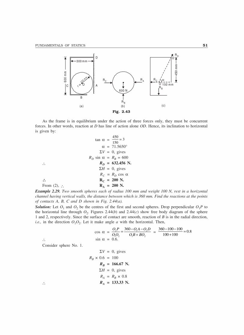
FUNDAMENTALS OF STATICS 51
O
B
A
D
(a) (b ) (c)
600
mm
300 m m
C
600 N
R B
RC R A R C
R B
R D
αO 150 m mr ≡
150 mm
D
Fig. 2.43
As the frame is in equilibrium under the action of three forces only, they must be concurrentforces. In other words, reaction at D has line of action alone OD. Hence, its inclination to horizontalis given by:
tan α =450
1503=
α = 71.5650°ΣV = 0, gives
RD sin α = RB = 600
∴ RD = 632.456 N.ΣH = 0, givesRC = RD cos α
∴∴∴∴∴ RC = 200 N.From (2), ∴ RA = 200 N.
Example 2.29. Two smooth spheres each of radius 100 mm and weight 100 N, rest in a horizontalchannel having vertical walls, the distance between which is 360 mm. Find the reactions at the pointsof contacts A, B, C and D shown in Fig. 2.44(a).Solution: Let O1 and O2 be the centres of the first and second spheres. Drop perpendicular O1P tothe horizontal line through O2. Figures 2.44(b) and 2.44(c) show free body diagram of the sphere1 and 2, respectively. Since the surface of contact are smooth, reaction of B is in the radial direction,i.e., in the direction O1O2. Let it make angle a with the horizontal. Then,
cos α = 2 1 2
1 2 1 2
360O P O A O D
O O O B BO
− −=+
= 360 100 100
0.8100 100
− − =+
∴ sin α = 0.6.
Consider sphere No. 1.
ΣV = 0, gives
RB × 0.6 = 100
RB = 166.67 N.
ΣH = 0, gives
RA = RB × 0.8
∴ RA = 133.33 N.
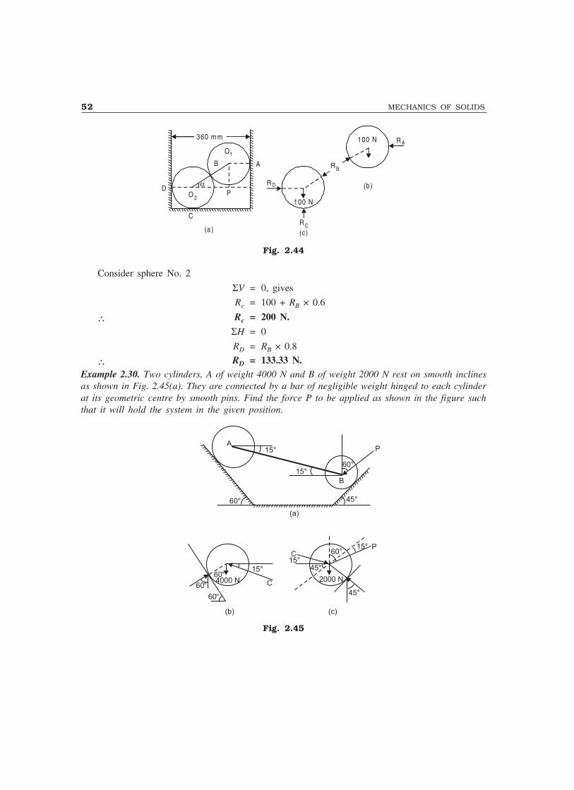
52 MECHANICS OF SOLIDS
360 m m
D
C
A
O1
αP
100 N
100 N
R C
R B
O 2
(b)
(c)(a )
B
R D
R A
Fig. 2.44
Consider sphere No. 2
ΣV = 0, gives
Rc = 100 + RB × 0.6
∴ Rc = 200 N.
ΣH = 0
RD = RB × 0.8
∴ RD = 133.33 N.Example 2.30. Two cylinders, A of weight 4000 N and B of weight 2000 N rest on smooth inclinesas shown in Fig. 2.45(a). They are connected by a bar of negligible weight hinged to each cylinderat its geometric centre by smooth pins. Find the force P to be applied as shown in the figure suchthat it will hold the system in the given position.
60°
(a)
A15°
60°
B
15°
45°
P
15°
15°
15°
60°
60°
60°
4000 N 2000 N
(b)
C
45°
45°
60°P
C
(c)
Fig. 2.45
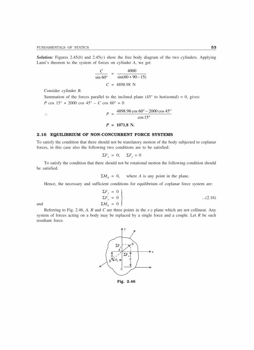
FUNDAMENTALS OF STATICS 53
Solution: Figures 2.45(b) and 2.45(c) show the free body diagram of the two cylinders. ApplyingLami’s theorem to the system of forces on cylinder A, we get
sin 60
C
°=
4000
sin(60 90 15)+ −
C = 4898.98 NConsider cylinder B.
Summation of the forces parallel to the inclined plane (45° to horizontal) = 0, gives:P cos 15° + 2000 cos 45° – C cos 60° = 0
∴ P = 4898.98 cos 60 2000 cos 45
cos 15
° − °°
P = 1071.8 N.
2.16 EQUILIBRIUM OF NON-CONCURRENT FORCE SYSTEMS
To satisfy the condition that there should not be translatory motion of the body subjected to coplanarforces, in this case also the following two conditions are to be satisfied:
ΣFx = 0; ΣFy = 0
To satisfy the condition that there should not be rotational motion the following condition shouldbe satisfied.
ΣMA = 0, where A is any point in the plane.
Hence, the necessary and sufficient conditions for equilibrium of coplanar force system are:
ΣFx = 0 ΣFy = 0 ...(2.16)
and ΣMA = 0Referring to Fig. 2.46, A, B and C are three points in the x-y plane which are not collinear. Any
system of forces acting on a body may be replaced by a single force and a couple. Let R be suchresultant force.
C
dΣFx
ΣF yR
y
d1d2B
xA
Fig. 2.46
�
��
��

54 MECHANICS OF SOLIDS
If the condition ΣMA = 0 is satisfied, we can conclude that the resultant R should be a forcepassing through A. If ΣMB = 0 is satisfied, the line of action of the resultant passes through B, i.e.,AB is the line of action. Now, if ΣMC = 0 is also satisfied, the resultant should be zero since the lineof action of the resultant (line AB) cannot pass through C also. Thus if A, B, C are not collinearpoints, the following conditions are necessary and sufficient conditions of equilibrium.
and
ΣΣΣ
M
M
M
A
B
C
===
�
��
��
0
0
0...(2.17)
The equilibrium Equations 2.16 are not independent of equilibrium Equations 2.15. Two of themare common to the two sets. Referring to Fig. 2.46, R can be resolved into its components perpendicularto and parallel to AC.
Then, ΣMC = (ΣFx)d
∴ if ΣMC = 0, (ΣFx)d = 0 or ΣFx = 0Now, ΣMB = 0
i.e., (ΣFx)d1 + (ΣFx)d2 = 0But ΣFx = 0∴ (ΣFy)d2 = 0
Since ABC are not colinear, d2 ≠ 0∴ ΣFy = 0
Thus, ΣMC = 0 is identical to ΣFx = 0 and ΣMB = 0 is identical to ΣFy = 0. Hence any one ofthe following sets may be used as equations of equilibrium:
(1) 0; 0; 0
(2) If line is not in direction,
0; 0; 0
(3) If line is not in direction
0; 0; 0
(4) If , and are non-collinear
0; 0; 0
x y A
y A B
x A B
A B C
F F M
AB y
F M M
AB x
F M M
A B C
M M M
Σ = Σ = Σ = Σ = Σ = Σ =Σ = Σ = Σ = Σ = Σ = Σ =
...(2.18)
It can be proved that if a system is in equilibrium under the action of three forces, those threeforces must be concurrent.
Let P1, P2 and P3 be the forces acting on a body as shown in Fig. 2.47 and let P1 and P2 intersectat A. Then applying moment equilibrium condition about A, we get
ΣMA = 0 i.e. P3d = 0
where d is distance of line of action of P3 from A.
Since P3 is not zero,d = 0, i.e. P3 also must pass through A.
Hence, the proposition is proved.
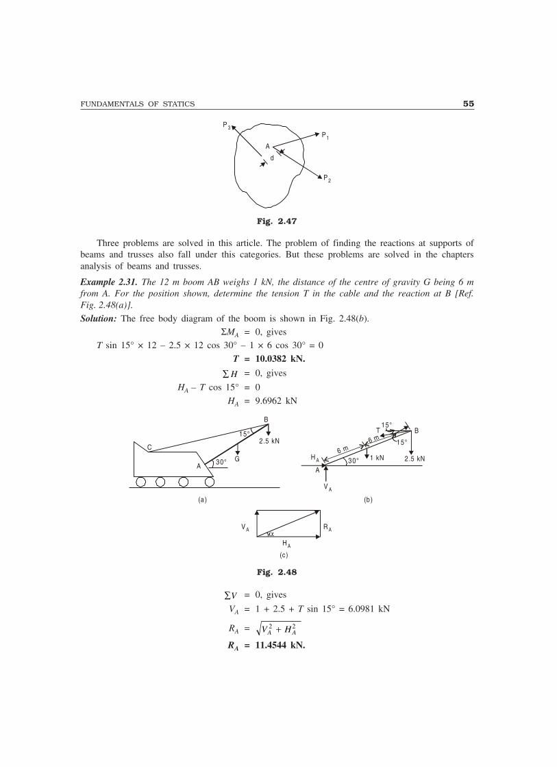
FUNDAMENTALS OF STATICS 55
d
A
P1
P2
P 3
Fig. 2.47
Three problems are solved in this article. The problem of finding the reactions at supports ofbeams and trusses also fall under this categories. But these problems are solved in the chaptersanalysis of beams and trusses.
Example 2.31. The 12 m boom AB weighs 1 kN, the distance of the centre of gravity G being 6 mfrom A. For the position shown, determine the tension T in the cable and the reaction at B [Ref.Fig. 2.48(a)].
Solution: The free body diagram of the boom is shown in Fig. 2.48(b).ΣMA = 0, gives
T sin 15° × 12 – 2.5 × 12 cos 30° – 1 × 6 cos 30° = 0
T = 10.0382 kN.
∑ H = 0, gives
HA – T cos 15° = 0
HA = 9.6962 kN
15°2 .5 kN
GA
C
B
(a) (b )
A
B
H A
V A
1 kN 2.5 kN30°
15°
15°
6 m6 m
30°
αH A
R AVA
(c)
T
Fig. 2.48
∑V = 0, gives
VA = 1 + 2.5 + T sin 15° = 6.0981 kN
RA = V HA A2 2+
RA = 11.4544 kN.
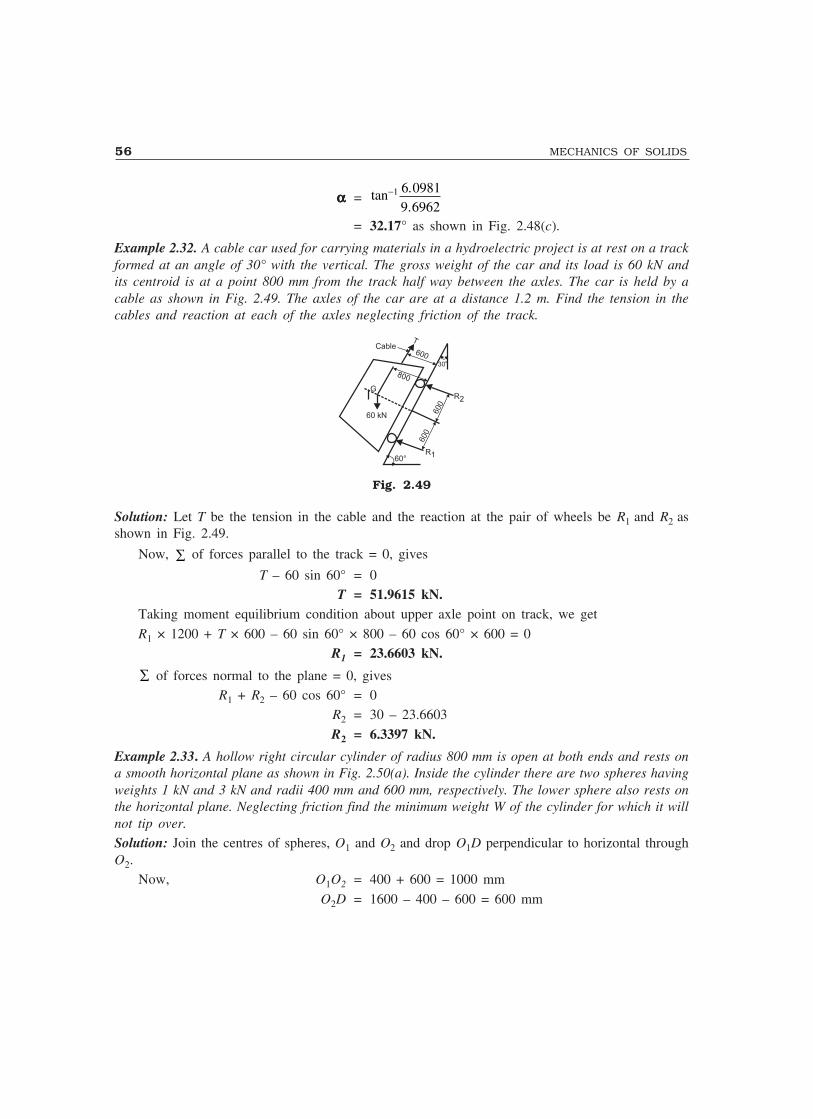
56 MECHANICS OF SOLIDS
ααααα = tan ..
−1 6 09819 6962
= 32.17° as shown in Fig. 2.48(c).
Example 2.32. A cable car used for carrying materials in a hydroelectric project is at rest on a trackformed at an angle of 30° with the vertical. The gross weight of the car and its load is 60 kN andits centroid is at a point 800 mm from the track half way between the axles. The car is held by acable as shown in Fig. 2.49. The axles of the car are at a distance 1.2 m. Find the tension in thecables and reaction at each of the axles neglecting friction of the track.
60 kN
60°R1
R2
600
600
600
800
G
CableT
30°
Fig. 2.49
Solution: Let T be the tension in the cable and the reaction at the pair of wheels be R1 and R2 asshown in Fig. 2.49.
Now, ∑ of forces parallel to the track = 0, gives
T – 60 sin 60° = 0T = 51.9615 kN.
Taking moment equilibrium condition about upper axle point on track, we get
R1 × 1200 + T × 600 – 60 sin 60° × 800 – 60 cos 60° × 600 = 0R1 = 23.6603 kN.
∑ of forces normal to the plane = 0, givesR1 + R2 – 60 cos 60° = 0
R2 = 30 – 23.6603
R2 = 6.3397 kN.
Example 2.33. A hollow right circular cylinder of radius 800 mm is open at both ends and rests ona smooth horizontal plane as shown in Fig. 2.50(a). Inside the cylinder there are two spheres havingweights 1 kN and 3 kN and radii 400 mm and 600 mm, respectively. The lower sphere also rests onthe horizontal plane. Neglecting friction find the minimum weight W of the cylinder for which it willnot tip over.
Solution: Join the centres of spheres, O1 and O2 and drop O1D perpendicular to horizontal throughO2.
Now, O1O2 = 400 + 600 = 1000 mm
O2D = 1600 – 400 – 600 = 600 mm
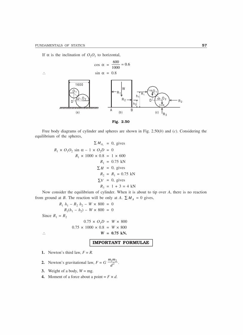
FUNDAMENTALS OF STATICS 57
If α is the inclination of O2O1 to horizontal,
cos α =600
10000 6= .
∴ sin α = 0.8
O 2
O 1
D
1 6 0 0
R 1
R 2
W
A
h 2
h 1 O 2
O 1
D R 2α
3 kN
1 k N
BR 3
R 1
(a) (b ) (c)
α
Fig. 2.50
Free body diagrams of cylinder and spheres are shown in Fig. 2.50(b) and (c). Considering theequilibrium of the spheres,
∑ MO2= 0, gives
R1 × O1O2 sin α – 1 × O2D = 0R1 × 1000 × 0.8 = 1 × 600
R1 = 0.75 kN
∑ H = 0, gives
R2 = R1 = 0.75 kN
∑V = 0, gives
R3 = 1 + 3 = 4 kNNow consider the equilibrium of cylinder. When it is about to tip over A, there is no reaction
from ground at B. The reaction will be only at A. ∑ M A = 0 gives,
R1 h1 – R2 h2 – W × 800 = 0R1(h1 – h2) – W × 800 = 0
Since R1 = R2
0.75 × O1D = W × 8000.75 × 1000 × 0.8 = W × 800
∴ W = 0.75 kN.
IMPORTANT FORMULAE
1. Newton’s third law, F = R.
2. Newton’s gravitational law, F = G m m
d1 2
2 .
3. Weight of a body, W = mg.4. Moment of a force about a point = F × d.
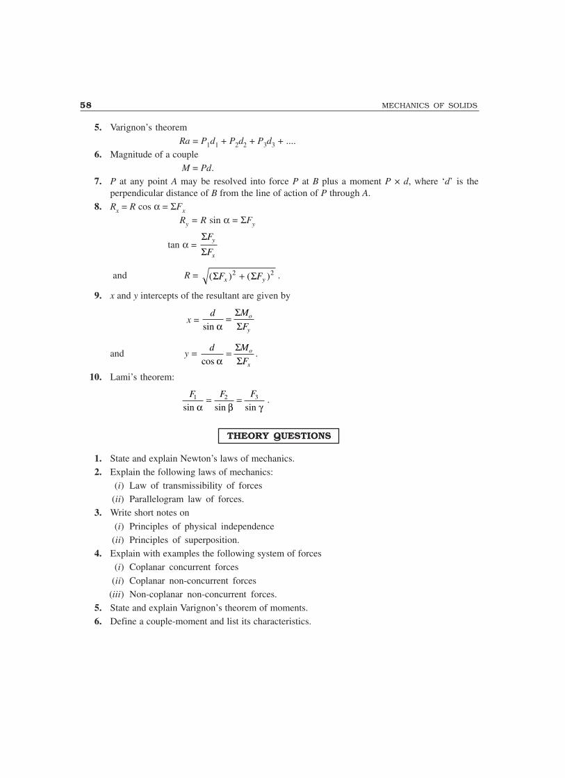
58 MECHANICS OF SOLIDS
5. Varignon’s theoremRa = P1d1 + P2d2 + P3d3 + ....
6. Magnitude of a couple M = Pd.
7. P at any point A may be resolved into force P at B plus a moment P × d, where ‘d’ is theperpendicular distance of B from the line of action of P through A.
8. Rx = R cos α = ΣFx
Ry = R sin α = ΣFy
tan α = ΣΣ
F
Fy
x
and R = ( ) ( )Σ ΣF Fx y2 2+ .
9. x and y intercepts of the resultant are given by
x = d M
Fo
ysin α=
ΣΣ
and y = d M
Fo
xcos α= Σ
Σ.
10. Lami’s theorem:
F F F1 2 3
sin sin sinα β γ= = .
THEORY QUESTIONS
1. State and explain Newton’s laws of mechanics.2. Explain the following laws of mechanics:
(i) Law of transmissibility of forces(ii) Parallelogram law of forces.
3. Write short notes on
(i) Principles of physical independence(ii) Principles of superposition.
4. Explain with examples the following system of forces(i) Coplanar concurrent forces
(ii) Coplanar non-concurrent forces(iii) Non-coplanar non-concurrent forces.
5. State and explain Varignon’s theorem of moments.6. Define a couple-moment and list its characteristics.

FUNDAMENTALS OF STATICS 59
PROBLEMS FOR EXERCISE
1. A body is subjected to the three forces as shown in Fig. 2.51. If possible determine the directionof the force F so that the resultant is in x-direction, when
(a) F = 5000 N(b) F = 3000 N
6 0°
2 00 0 N
x
F
θ
3 00 0 N
Fig. 2.51
[Ans. (a) 36.87°; (b) Not possible]2. The frictionless pulley A shown in Fig. 2.52 is supported by two bars AB and AC which are
hinged at B and C to a vertical wall. The flexible cable DG hinged at D, goes over the pulley andsupports a load of 20 kN at G. The angles between the various members are shown in the figure.Determine the forces in the bars AB and AC. Neglect the size of the pulley.
A
G
20 kN
30°D
30°
B
C
Fig. 2.52
[Hint: Force in AD = 20 kN, tensile] [Ans. FAB = 0; FAC = 34.641 kN]3. A cord supported at A and B carries a load of 10 kN at D and a load of W at C a shown in
Fig. 2.53. Find the value of W so that CD remains horizontal. [Ans. W = 30 kN]
6 0 °
C D
B
3 0 °
W 10 kN
A
Fig. 2.53
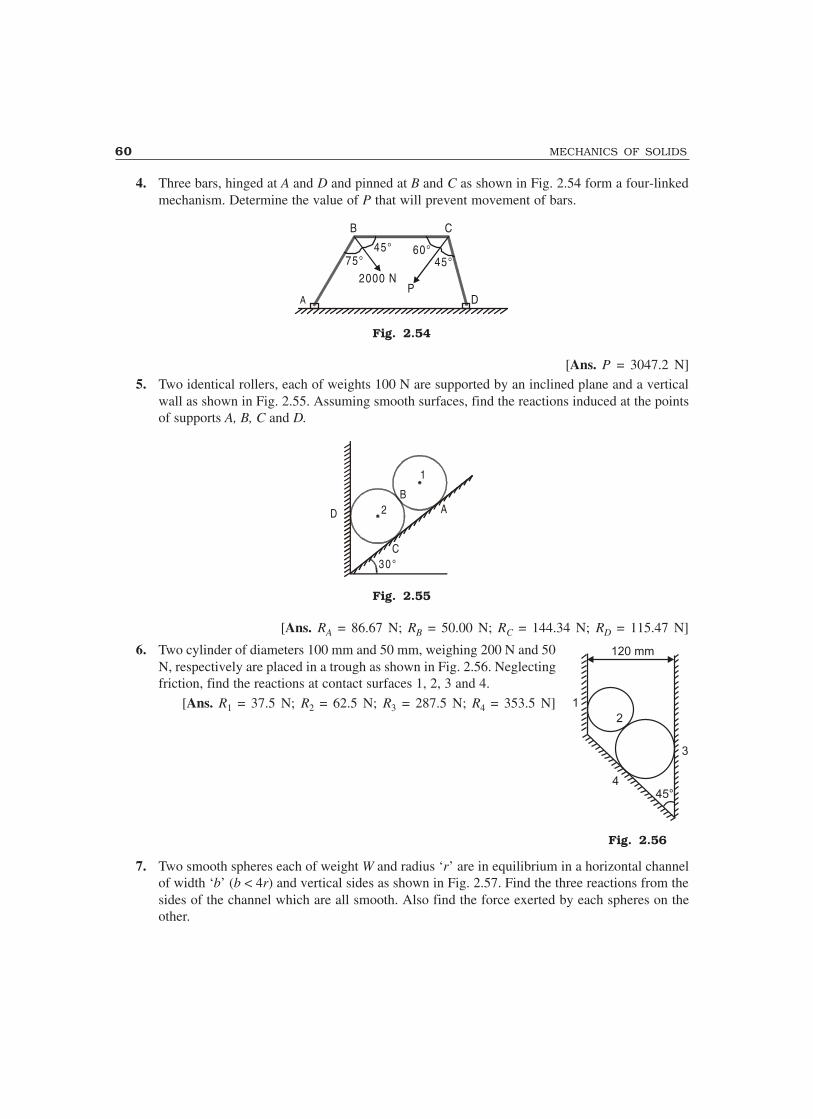
60 MECHANICS OF SOLIDS
4. Three bars, hinged at A and D and pinned at B and C as shown in Fig. 2.54 form a four-linkedmechanism. Determine the value of P that will prevent movement of bars.
P
45°60°45°
75°
B C
D
2000 N
A
Fig. 2.54
[Ans. P = 3047.2 N]5. Two identical rollers, each of weights 100 N are supported by an inclined plane and a vertical
wall as shown in Fig. 2.55. Assuming smooth surfaces, find the reactions induced at the pointsof supports A, B, C and D.
D 2
1
B
C
A
3 0 °
Fig. 2.55
[Ans. RA = 86.67 N; RB = 50.00 N; RC = 144.34 N; RD = 115.47 N]
6. Two cylinder of diameters 100 mm and 50 mm, weighing 200 N and 50N, respectively are placed in a trough as shown in Fig. 2.56. Neglectingfriction, find the reactions at contact surfaces 1, 2, 3 and 4.
[Ans. R1 = 37.5 N; R2 = 62.5 N; R3 = 287.5 N; R4 = 353.5 N]
7. Two smooth spheres each of weight W and radius ‘r’ are in equilibrium in a horizontal channelof width ‘b’ (b < 4r) and vertical sides as shown in Fig. 2.57. Find the three reactions from thesides of the channel which are all smooth. Also find the force exerted by each spheres on theother.
1
2
3
445°
120 mm
Fig. 2.56
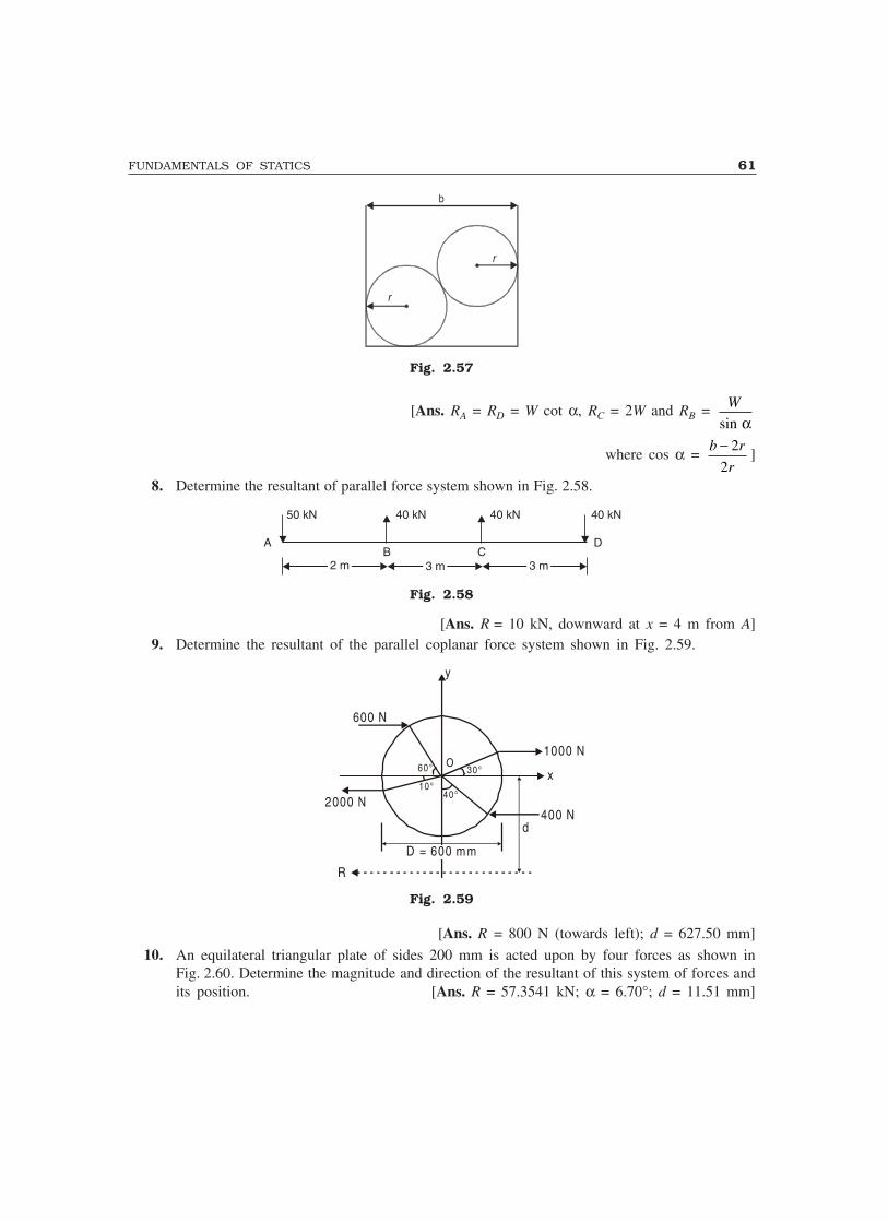
FUNDAMENTALS OF STATICS 61
b
r
r
Fig. 2.57
[Ans. RA = RD = W cot α, RC = 2W and RB = sin
W
α
where cos α = 2
2
b r
r
−]
8. Determine the resultant of parallel force system shown in Fig. 2.58.
50 kN 40 kN 40 kN 40 kN
A D
2 m2 m 3 m3 m 3 m3 mB C
Fig. 2.58
[Ans. R = 10 kN, downward at x = 4 m from A]9. Determine the resultant of the parallel coplanar force system shown in Fig. 2.59.
D = 600 mm
d400 N
1000 N
y
x30°60°
10°40°
2000 N
600 N
R
O
Fig. 2.59
[Ans. R = 800 N (towards left); d = 627.50 mm]
10. An equilateral triangular plate of sides 200 mm is acted upon by four forces as shown inFig. 2.60. Determine the magnitude and direction of the resultant of this system of forces andits position. [Ans. R = 57.3541 kN; α = 6.70°; d = 11.51 mm]

62 MECHANICS OF SOLIDS
5 0 kN
B
C
6 0 kN
3 0 kN
8 0 kN
A
R d
Fig. 2.60
11. Determine the magnitude, direction and the line of application of the equilibriant of the set offorces shown in Fig. 2.61, which will keep the plane body ABCDEFGH in equilibrium.
[Ans. E = 23.6517 kN; α = 24.37°; x from A = 1.041 m]
0.5 m 10 kN
30 kNBA
C F
20 kN
0.5 m
H
45°
α1 m
G
D E
10 kN20 kN
20 kN
0.5 m
0.5 m
1.0 m
10 kNE
Fig. 2.61
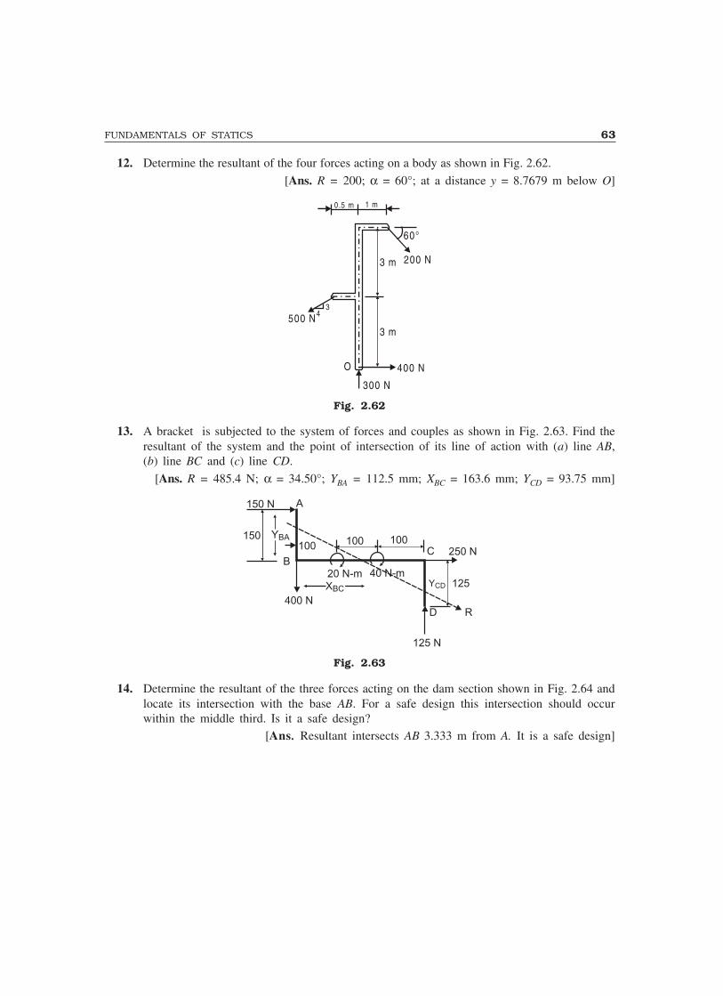
FUNDAMENTALS OF STATICS 63
12. Determine the resultant of the four forces acting on a body as shown in Fig. 2.62.
[Ans. R = 200; α = 60°; at a distance y = 8.7679 m below O]
0.5 m 1 m
60°
200 N
400 N
3 m
3 m
500 N3
4
O
300 N
Fig. 2.62
13. A bracket is subjected to the system of forces and couples as shown in Fig. 2.63. Find theresultant of the system and the point of intersection of its line of action with (a) line AB,(b) line BC and (c) line CD.
[Ans. R = 485.4 N; α = 34.50°; YBA = 112.5 mm; XBC = 163.6 mm; YCD = 93.75 mm]
A150 N
150
B
XBCXBC
20 N-m 40 N-m
100 100 100250 NC
YCD 125
D R400 N
125 N
YBAYBA
Fig. 2.63
14. Determine the resultant of the three forces acting on the dam section shown in Fig. 2.64 andlocate its intersection with the base AB. For a safe design this intersection should occurwithin the middle third. Is it a safe design?
[Ans. Resultant intersects AB 3.333 m from A. It is a safe design]

64 MECHANICS OF SOLIDS
6 m
60°
120 kN
2 m
3 m
50 kN
1 m30 kN
BA
Fig. 2.64
15. A 1000 N cylinder is supported by a horizontal rod AB and a smooth uniform rod CD whichweighs 500 N as shown in Fig. 2.65. Assuming the pins at A, B, C and D, to be frictionlessand weight of AB negligible, find the reactions at C and D.
[Ans. VC = 937.1 N (upward); HC = 577.3 N (towards left) RD = 562.9 N (upward)]
A B
3 0°3 .5 m
1.5 m
C
D
Fig. 2.65
16. The frame shown in Fig. 2.66 is supported by a hinge at E and by a roller at D. Determinethe horizontal and vertical components of the reactions at hinge C as it acts upon memberBD. [Ans. HC = 140 N (towards right); VC = 35 N (upward)]
Fig. 2.66

3Trusses
A truss is a structure made up of slender members pin-connected at ends and is capable of takingloads at joints. They are used as roof trusses to support sloping roofs and as bridge trusses to supportdeck. In many machines steel trusses are used. Transmission towers are also the examples of trusses.In the case of wooden trusses, the ends are connected by making suitable joints or by nailing andbolting whereas in steel trusses ends are connected by bolting or welding. The trusses are also knownas ‘pinjointed frames’.
A truss in which all the members lie in a single plane is called as a plane truss. In such trussesloads act in the plane of the truss only. Roof trusses and bridge trusses can be considered as planetrusses. If all the members of a truss do not lie in a single plane, then it is called a space truss. Tripodand transmission towers are the examples of space trusses. In this chapter, the analysis of only planetrusses is considered.
3.1 PERFECT, DEFICIENT AND REDUNDANT TRUSSES
A pinjointed truss which has got just sufficient number of members toresist the loads without undergoing appreciable deformation in shape iscalled a perfect truss. Triangular truss is the simplest perfect truss and ithas three joints and three members (Fig. 3.1). Perfect trusses with four andfive joints are shown in Figs. 3.2 and 3.3 respectively.
It may be observed that to increase one joint in a perfect truss, twomore members are required. Hence the following expression may be writtendown as the relationship between number of joints j, and the number ofmembers m, in a perfect truss.
m = 2j – 3 ...(3.1)
However, the above equation gives only a necessary, butnot a sufficient condition of a perfect truss. For example, thetwo trusses shown in Fig. 3.4(a) and (b) have the same numberof members and joints. The truss shown in Fig. 3.4(a) is per-fect whereas the one shown in Fig. 3.4(b) is not capable ofretaining its shape if loaded at the joint marked 6. Therefore,the only necessary and sufficient condition of a perfect trussis that it should retain its shape when load is applied at anyjoint in any direction.
65
Fig. 3.2
Fig. 3.1
1 2
31 3
2
3
4
2
15
1
2
3
4

66 MECHANICS OF SOLIDS
3
1
3
2 5
7
6
4
1
2 4
5
Fig. 3.3
31
2 4 6
5
(a)3
1
2 46
5
(b)
P
Fig. 3.4
A truss is said to be deficient if the number of members init are less than that required for a perfect truss. Such trussescannot retain their shape when loaded. A deficient truss is shownin Fig. 3.5.
A truss is said to be redundant if the number of members init are more than that required in a perfect truss. Such trussescannot be analysed by making use of the equations of equilibriumalone. Thus, a redundant truss is statically indeterminate. Eachextra member adds one degree of indeterminancy. For the analysisof such members the consistency of deformations is to beconsidered. The truss shown in the Fig. 3.6 is a typical redundanttruss. In this truss one diagonal member in each panel is extra.Hence it is a two-degree redundant truss.
In this chapter, only the analysis of perfect frames isconsidered.
3.2 ASSUMPTIONS
In the theory that is going to be developed in this chapter, the following assumptions are made:
(1) The ends of the members are pin-connected (hinged);(2) The loads act only at the joints;
(3) Self-weights of the members are negligible;(4) Cross-section of the members is uniform.
If at all the cross-section varies, the centre of gravity of the section is assumed to be locatedalong the same longitudinal line.
In reality the members are connected by bolting, riveting or by welding. No special care is takento ensure perfect pin-connections. However, experiments have shown that assuming pin-connectedends is quite satisfactory since the members used are slender.
Fig. 3.6
Fig. 3.5
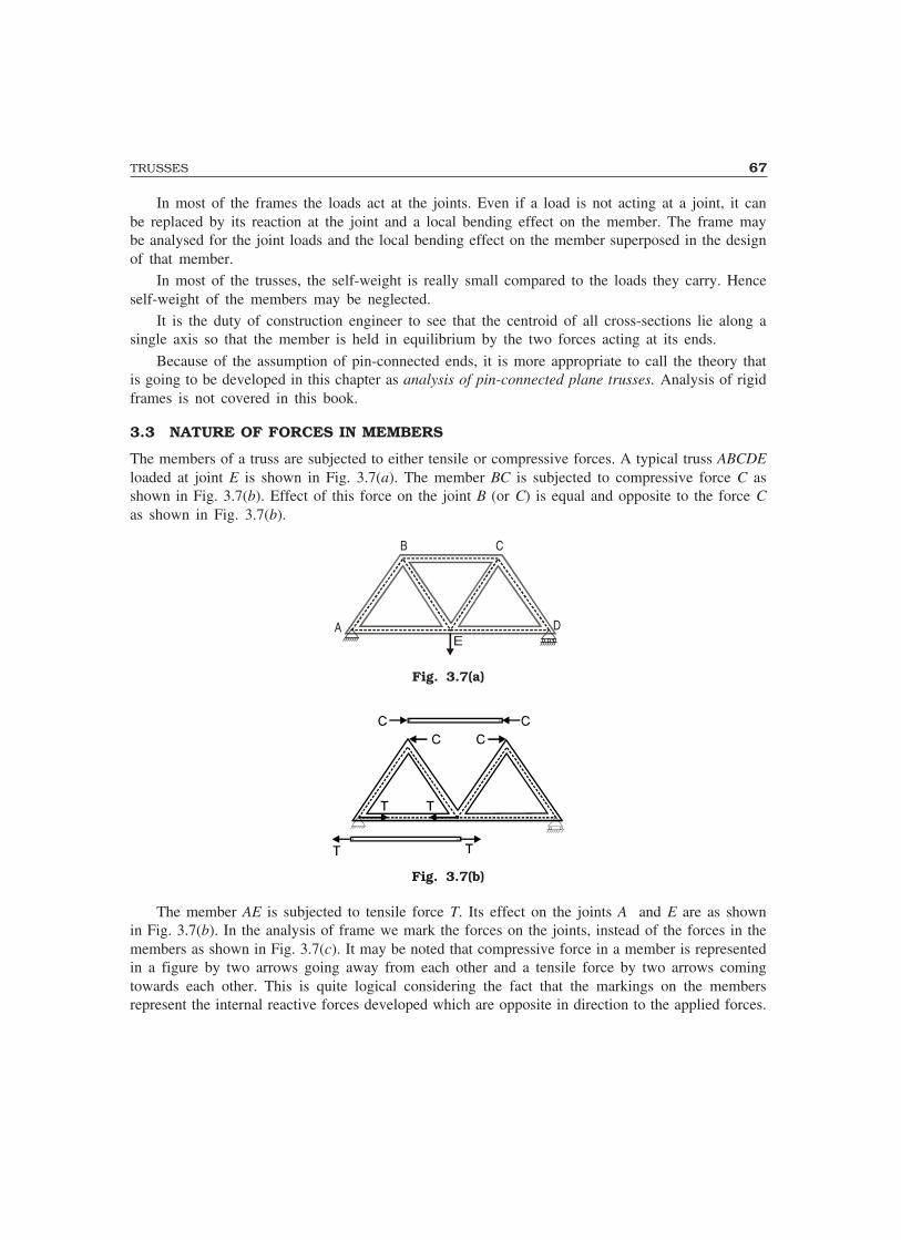
TRUSSES 67
In most of the frames the loads act at the joints. Even if a load is not acting at a joint, it canbe replaced by its reaction at the joint and a local bending effect on the member. The frame maybe analysed for the joint loads and the local bending effect on the member superposed in the designof that member.
In most of the trusses, the self-weight is really small compared to the loads they carry. Henceself-weight of the members may be neglected.
It is the duty of construction engineer to see that the centroid of all cross-sections lie along asingle axis so that the member is held in equilibrium by the two forces acting at its ends.
Because of the assumption of pin-connected ends, it is more appropriate to call the theory thatis going to be developed in this chapter as analysis of pin-connected plane trusses. Analysis of rigidframes is not covered in this book.
3.3 NATURE OF FORCES IN MEMBERS
The members of a truss are subjected to either tensile or compressive forces. A typical truss ABCDEloaded at joint E is shown in Fig. 3.7(a). The member BC is subjected to compressive force C asshown in Fig. 3.7(b). Effect of this force on the joint B (or C) is equal and opposite to the force Cas shown in Fig. 3.7(b).
A
B C
D
Fig. 3.7(a)
Fig. 3.7(b)
The member AE is subjected to tensile force T. Its effect on the joints A and E are as shownin Fig. 3.7(b). In the analysis of frame we mark the forces on the joints, instead of the forces in themembers as shown in Fig. 3.7(c). It may be noted that compressive force in a member is representedin a figure by two arrows going away from each other and a tensile force by two arrows comingtowards each other. This is quite logical considering the fact that the markings on the membersrepresent the internal reactive forces developed which are opposite in direction to the applied forces.

68 MECHANICS OF SOLIDS
COM PRESSION
TENSIO NFig. 3.7(c)
3.4 METHODS OF ANALYSIS
The following three methods are available for the analysis of pin-connected frames:(1) Method of joints(2) Method of section(3) Graphical method.The first two are analytical methods and they are dealt in this chapter.
3.5 METHOD OF JOINTS
At each joint the forces in the members meeting and the loads acting, if any, constitute a system ofconcurrent forces. Hence, two independent equations of equilibrium can be formed at each joint.First, a joint is selected where there are only two unknown forces. Many times such a joint can beidentified only after finding the reaction at the support by considering the equilibrium of the entireframe. Then making use of the two equations of equilibrium at that joint the two unknown forcesare found. Then, the next joint is selected for analysis where there are now only two unknown forces.Thus, the analysis proceeds from joints to joint to find the forces in all the members.
It may be noted that if there are j number of joints, 2j number of the equations can be formed.There will be three reactions in a general determinate truss. The force in each member is unknown.Hence, if there are m number of members, the total number of unknowns will be m+3. A problemcan be analysed if there are as many equations as there are unknowns. Hence, a frame analysisproblem is determinate if:
2j = m + 3 ...(3.2)This equation is the same as Equation 3.1 which was derived on the consideration of a perfect
frame. Hence, a perfect frame is determinate. If m > 2j – 3, then the number of unknowns is morethan the number of equations. Hence, a redundant frame is indeterminate. If m < 2j – 3, then thenumber of equations is more than the number of unknowns. Since a set of solutions can satisfy suchequations, it shows instability of the structure. Hence, a deficient frame is not stable.
The method of joints is illustrated with the examples 3.1 to 3.7.
EXAMPLES
Example 3.1. Find the forces in all the members of thetruss shown in Fig. 3.8(a). Tabulate the results.
Fig. 3.8(a)
E
A B
3 m
θ θD
40 kN 40 kN3 m 3 m
C
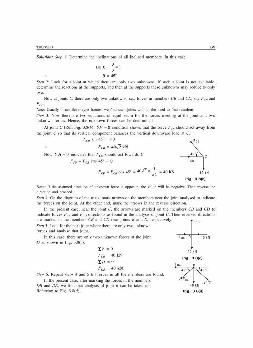
TRUSSES 69
Solution: Step 1: Determine the inclinations of all inclined members. In this case,
tan θ = 3
31=
∴ θθθθθ = 45°Step 2: Look for a joint at which there are only two unknowns. If such a joint is not available,determine the reactions at the supports, and then at the supports these unknowns may reduce to onlytwo.
Now at joints C, there are only two unknowns, i.e., forces in members CB and CD, say FCB andFCD.Note: Usually in cantilever type frames, we find such joints without the need to find reactions.
Step 3: Now there are two equations of equilibrium for the forces meeting at the joint and twounknown forces. Hence, the unknown forces can be determined.
At joint C [Ref. Fig. 3.8(b)] ∑ =V 0 condition shows that the force FCB should act away fromthe joint C so that its vertical component balances the vertical downward load at C.
FCB sin 45° = 40
∴ FCB = 40 2 kN
Now ∑ =H 0 indicates that FCD should act towards C.
FCD – FCB cos 45° = 0
FCD = FCB cos 45° = 40 21
2× = 40 kN
Note: If the assumed direction of unknown force is opposite, the value will be negative. Then reverse thedirection and proceed.
Step 4: On the diagram of the truss, mark arrows on the members near the joint analysed to indicatethe forces on the joint. At the other end, mark the arrows in the reverse direction.
In the present case, near the joint C, the arrows are marked on the members CB and CD toindicate forces FCB and FCD directions as found in the analysis of joint C. Then reversed directionsare marked in the members CB and CD near joints B and D, respectively.
Step 5: Look for the next joint where there are only two unknownforces and analyse that joint.
In this case, there are only two unknown forces at the jointD as shown in Fig. 3.8(c).
∑V = 0
FDB = 40 kN
∑ H = 0
FDE = 40 kNStep 6: Repeat steps 4 and 5 till forces in all the members are found.
In the present case, after marking the forces in the membersDB and DE, we find that analysis of joint B can be taken up.Referring to Fig. 3.8(d).
Fig. 3.8(b)
Fig. 3.8(d)
Fig. 3.8(c)
F D E
FD B
4 0 kN
4 0 kN
D
F BE
F BA
4 0 kN
B
4 0 2
4 5 ° 4 5 °
F C D
F C B
C
4 0 kN
4 5 °
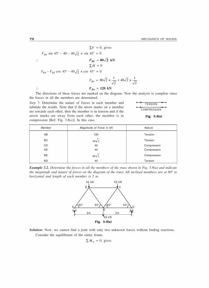
70 MECHANICS OF SOLIDS
∑V = 0, gives
FBE sin 45° – 40 – 40 2 × sin 45° = 0
∴ FBE = 80 2 kN
∑ H = 0
FBA – FBE cos 45° – 40 2 × cos 45° = 0
FBA = 80 21
240 2
1
2× ×+
∴ FBA = 120 kNThe directions of these forces are marked on the diagram. Now the analysis is complete since
the forces in all the members are determined.
Step 7: Determine the nature of forces in each member andtabulate the results. Note that if the arrow marks on a memberare towards each other, then the member is in tension and if thearrow marks are away from each other, the member is incompression [Ref. Fig. 3.8(e)]. In this case,
Member Magnitude of Force in kN Nature
AB 120 Tension
BC 40 2 Tension
CD 40 Compression
DE 40 Compression
BE 80 2 Compression
BD 40 Tension
Example 3.2. Determine the forces in all the members of the truss shown in Fig. 3.9(a) and indicatethe magnitude and nature of forces on the diagram of the truss. All inclined members are at 60° tohorizontal and length of each member is 2 m.
B C
6 0 ° 6 0 ° 6 0 ° 6 0 °A D
E
4 0 kN 5 0 kN
6 0 kN2 m 2 m
Fig. 3.9(a)
Solution: Now, we cannot find a joint with only two unknown forces without finding reactions.
Consider the equilibrium of the entire frame.
∑ M A = 0, gives
Fig. 3.8(e)
TE NSIO N
CO M PRESSIO N
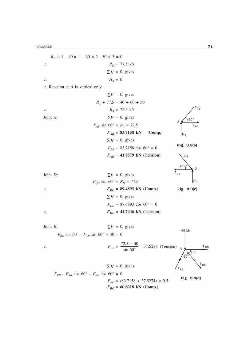
TRUSSES 71
RD × 4 – 40 × 1 – 60 × 2 – 50 × 3 = 0
∴ RD = 77.5 kN
∑ H = 0, gives
∴ HA = 0
∴ Reaction at A is vertical only
∑V = 0, gives
RA + 77.5 = 40 + 60 + 50
∴ RA = 72.5 kN
Joint A: ∑V = 0, gives
FAB sin 60° = RA = 72.5
FAB = 83.7158 kN (Comp.)
∑ H = 0, gives
FAE – 83.7158 cos 60° = 0
FAE = 41.8579 kN (Tension)
Joint D: ∑V = 0, gives
FDC sin 60° = RD = 77.5
∴ FDC = 89.4893 kN (Comp.)
∑ H = 0, gives
FDE – 87.4893 cos 60° = 0
∴ FDE = 44.7446 kN (Tension)
Joint B: ∑V = 0, gives
FBE sin 60° – FAB sin 60° + 40 = 0
∴ FBE =72 5 40
6037 5278
.sin
.−
°= (Tension)
∑ H = 0, gives
FBC – FAB cos 60° – FBE cos 60° = 0
FBC = (83.7158 + 37.5274) × 0.5
FBC = 60.6218 kN (Comp.)
Fig. 3.9(b)
FAE
FAB
A6 0 °
R A
Fig. 3.9(c)
F D E
F D C
D6 0 °
R D
Fig. 3.9(d)
BF BC
F BEF AB
6 0 °6 0 °
4 0 kN
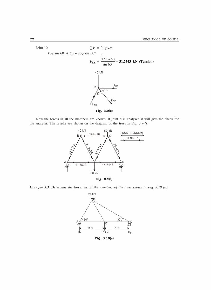
72 MECHANICS OF SOLIDS
Joint C: ∑V = 0, gives
FCE sin 60° + 50 – FDC sin 60° = 0
FCE =77 5 50
60
.
sin
−°
= 31.7543 kN (Tension)
BF BC
F BEF AB
6 0 °6 0 °
4 0 kN
Fig. 3.9(e)
Now the forces in all the members are known. If joint E is analysed it will give the check forthe analysis. The results are shown on the diagram of the truss in Fig. 3.9(f).
B C
A DE
4 0 kN 5 0 kN
83.7
158
31.7
543
37 .52 78
6 0 .6 2 1 8
4 1 .8 5 7 9 4 4 .7 4 4 6
89.48 93
CO M PRES SIO N
TE NSIO N
6 0 kN
Fig. 3.9(f)
Example 3.3. Determine the forces in all the members of the truss shown in Fig. 3.10 (a).
60° 30°�
3 m3 m 3 m3 m
20 kN
AC
D
B
RA RD10 kN
Fig. 3.10(a)
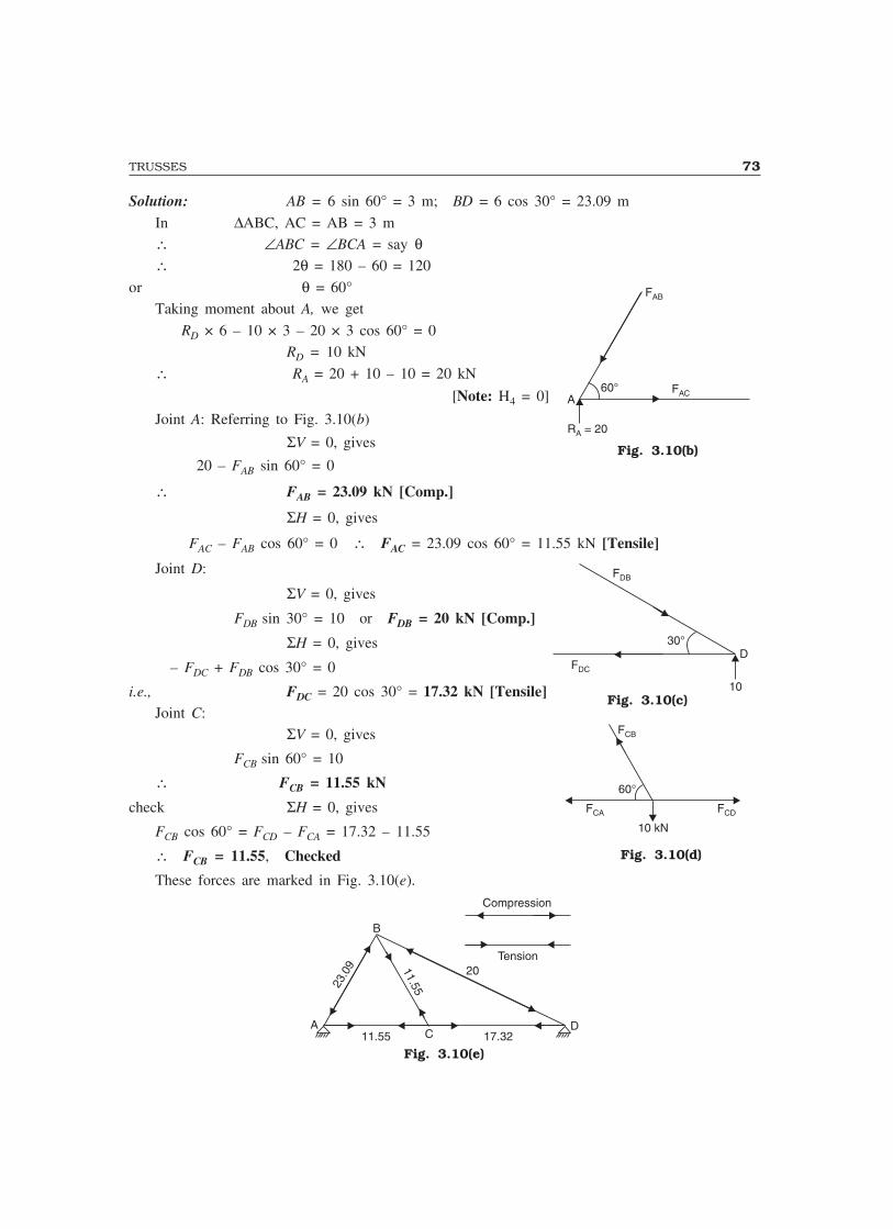
TRUSSES 73
Solution: AB = 6 sin 60° = 3 m; BD = 6 cos 30° = 23.09 m
In ∆ABC, AC = AB = 3 m∴ ∠ABC = ∠BCA = say θ∴ 2θ = 180 – 60 = 120
or θ = 60°Taking moment about A, we get
RD × 6 – 10 × 3 – 20 × 3 cos 60° = 0RD = 10 kN
∴ RA = 20 + 10 – 10 = 20 kN
[Note: H4 = 0]
Joint A: Referring to Fig. 3.10(b)
ΣV = 0, gives
20 – FAB sin 60° = 0
∴ FAB = 23.09 kN [Comp.]
ΣH = 0, gives
FAC – FAB cos 60° = 0 ∴ FAC = 23.09 cos 60° = 11.55 kN [Tensile]
Joint D:
ΣV = 0, gives
FDB sin 30° = 10 or FDB = 20 kN [Comp.]
ΣH = 0, gives
– FDC + FDB cos 30° = 0
i.e., FDC = 20 cos 30° = 17.32 kN [Tensile]Joint C:
ΣV = 0, gives
FCB sin 60° = 10
∴ FCB = 11.55 kN
check ΣH = 0, gives
FCB cos 60° = FCD – FCA = 17.32 – 11.55
∴ FCB = 11.55, Checked
These forces are marked in Fig. 3.10(e).
AC
D
B
23.0
9 11.55
20
11.55 17.32
Compression
Tension
Fig. 3.10(e)
60°A
FAB
FAC
R = 20A
Fig. 3.10(b)
30°
10
FDC
FDB
D
Fig. 3.10(c)
60°
FCB
FCA FCD
10 kN
Fig. 3.10(d)
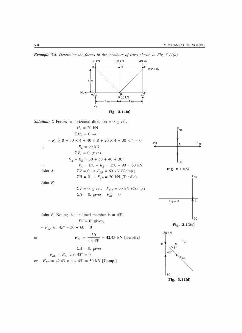
74 MECHANICS OF SOLIDS
Example 3.4. Determine the forces in the members of truss shown in Fig. 3.11(a).
B C D
30 kN 50 kN 40 kN
20 kN
E
4 m4 m
4 m4 m 4 m4 m30 kNFA
VA
HA
Fig. 3.11(a)
Solution: Σ Forces in horizontal direction = 0, gives,
HA = 20 kN
ΣMA = 0 →– RE × 8 + 50 × 4 + 40 × 8 + 20 × 4 + 30 × 4 = 0
∴ RE = 90 kN
ΣVA = 0, gives
VA + RE = 30 + 50 + 40 + 30
∴ VA = 150 – RE = 150 – 90 = 60 kNJoint A: ΣV = 0 → FAB = 60 kN (Comp.)
ΣH = 0 → FAF = 20 kN (Tensile)Joint E:
ΣV = 0, gives, FED = 90 kN (Comp.)ΣH = 0, gives, FEF = 0
Joint B: Noting that inclined member is at 45°,
ΣV = 0; gives,
– FBF sin 45° – 30 + 60 = 0
or FBF = 30
45sin ° = 42.43 kN [Tensile]
ΣH = 0, gives
– FBC + FBF cos 45° = 0
or FBC = 42.43 × cos 45° = 30 kN [Comp.]
FAB
60
FAF20 A
Fig. 3.11(b)
FED
90
EF = 0EF
Fig. 3.11(c)
30 kN
45°45°
FBC
FBF
60
B
Fig. 3.11(d)
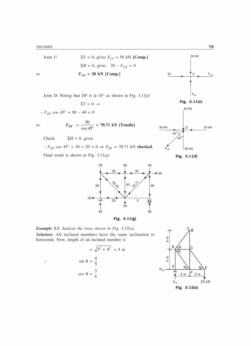
TRUSSES 75
Joint C: ΣV = 0, gives FCF = 50 kN [Comp.]
ΣH = 0, gives 30 – FCD = 0
or FCD = 30 kN [Comp.]
Joint D: Noting that DF is at 45° as shown in Fig. 3.11(f)
ΣV = 0 →
– FDF cos 45° + 90 – 40 = 0
or FDF = 50
45cos ° = 70.71 kN [Tensile]
Check ΣH = 0, gives
– FDF cos 45° + 30 + 20 = 0 or FDF = 70.71 kN checked.
Final result is shown in Fig. 3.11(g)
30 50 40
20
30
60 90
60 90
42.43 70.7
150
30 30
20 020
Fig. 3.11(g)
Example 3.5. Analyse the truss shown in Fig. 3.12(a).
Solution: All inclined members have the same inclination tohorizontal. Now, length of an inclined member is
= 2 23 4+ = 5 m
∴ sin θ =4
5
cos θ =3
5
30 C
50 kN
FCD
FCF
Fig. 3.11(e)
30 kN D
40 kN
90 kN
45°
45°
FDF
20 kN
Fig. 3.11(f)
Fig. 3.12(a)
3 m 3 m
VA 20 kN
H A
4 m
4 m
A
B
C
D
E
θθ
θ θF

76 MECHANICS OF SOLIDS
As soon as a joint is analysed the forces on the joint are marked on members [Fig. 3.12(b)]
V A 2 0 k N
H A
θ
θ θ20 kN
15 kN 15 kN
15 kN
20 kN
25 kNOO
25 k
N
R C
A
B D
C
FE
Fig. 3.12(b)
Joint E: ∑V = 0, gives
FED × 4
5 – 20 = 0
∴ FED = 25 kN (Tension)
∑ H = 0, gives
FEF – FED cos θ = 0
∴ FEF = 253
5× = 15 kN (Comp.)
At this stage as no other joint is having only two unknowns, no further progress is possible. Letus find the reactions at the supports considering the whole structure. Let the reaction be as shownin Fig. 3.12(b).
∑ M A = 0, gives
RC × 8 – 20 × 6 = 0
RC = 15 kN
∑V = 0, gives
VA = 20 kN
∑ H = 0, gives
HA = RC = 15 kN
Joint A: ∑V = 0, gives
FAB – VA = 0
FAB = 20 kN (Comp.)
∑ H = 0, gives
FAF – HA = 0
FAF = 15 kN (Comp.)
Fig. 3.12(c)
F EF
F ED
2 0 kN
θE
H A
F AB
F AF
A
V A
Fig. 3.12(d)

TRUSSES 77
Joint C: ∑ H = 0, gives
FCB × 3
5 – RC = 0
FCB = 15 × 5
3 = 25 kN (Comp.)
∑V = 0, gives
FCD = FCB sin θ
= 25 × 4
5 = 20 kN (Tension)
Joint B: ∑V = 0, gives
FBF × 4
5 – FBC ×
4
5 + FAB = 0
FBF × 4
5= 25 ×
4
5 – 20 = 0
∴ FBF = 0
∑ H = 0, gives
FBD – 25 × 3
5= 0
FBD = 15 kN (Tension)
Joint F:
∑V = 0
FFD = 0 (since FBF = 0)
Note: When three members are meeting at an unloaded joint and out of them two are collinear, then the forcein third member will be zero. Such situations are illustrated in Fig. 3.12(h) and (i).
A
C B D
A
C B D
Fig. 3.12(h) and (i)
Fig. 3.12(f)
F BD
F BC
θB
FBFF AB
θ
Fig. 3.12(g)
R C
FC DFC B
Fig. 3.12(e)

78 MECHANICS OF SOLIDS
Example 3.6. Find the forces in all the members of the truss shown in Fig. 3.13(a).
Solution: tan θ1 =4
6 = 33.69°
θ2 = tan ×− ���
���
1 8
3
1
2 = 53.13°
θ3 = tan− ������
1 4
3 = 53.13°
θ2= θ3 = θ
sin θ =4
5 and cos θ =
3
5
θ3θ2θ1θ1
C
G
H
2 m
2 m 2 m 2 m 3 mFDBA
E
20 kN12 kN
Fig. 3.13(a)
Joint-by-joint analysis is carried out as given below and the joint forces are marked in Fig. 3.13(b).Then nature of the force in the members is determined.
C
G
HFDBA
E
15 kN 15 kN 15 kN 15 kN
R A
1 8 .0 278kN
18 .0 27 8kN
1 8 .0 278kN
25 kN
R G
20 kN12 kN
C O M P R E S S IO N
T E N S IO N
Fig. 3.13(b)
Joint H: ∑V = 0, gives
FHG sin θ3 = 20
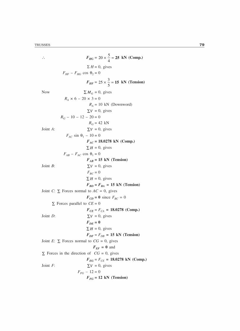
TRUSSES 79
∴ FHG = 205
4× = 25 kN (Comp.)
Σ H = 0, gives
FHF – FHG cos θ2 = 0
FHF = 253
5× = 15 kN (Tension)
Now ∑ MG = 0, gives
RA × 6 – 20 × 3 = 0
RA = 10 kN (Downword)
∑V = 0, gives
RG – 10 – 12 – 20 = 0
RG = 42 kN
Joint A: ∑V = 0, gives
FAC sin θ1 – 10 = 0
FAC = 18.0278 kN (Comp.)
∑ H = 0, gives
FAB – FAC cos θ1 = 0
FAB = 15 kN (Tension)
Joint B: ∑V = 0, gives
FBC = 0
∑ H = 0, gives
FBD = FBA = 15 kN (Tension)
Joint C: ∑ Forces normal to AC = 0, gives
FCD = 0 since FBC = 0
∑ Forces parallel to CE = 0
FCE = FCA = 18.0278 (Comp.)
Joint D: ∑V = 0, gives
FDE = 0
∑ H = 0, gives
FDF = FDB = 15 kN (Tension)
Joint E: ∑ Forces normal to CG = 0, gives
FEF = 0 and
∑ Forces in the direction of CG = 0, gives
FEG = FCE = 18.0278 kN (Comp.)
Joint F: ∑V = 0, gives
FFG – 12 = 0FFG = 12 kN (Tension)
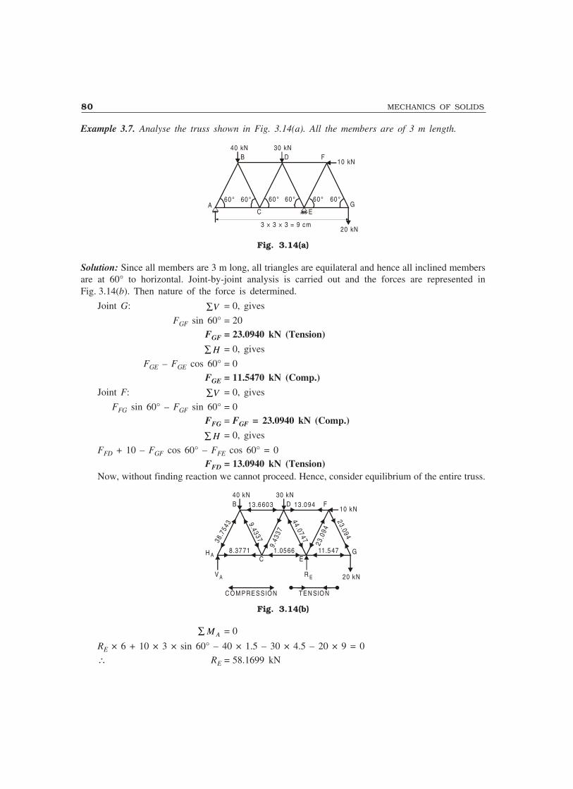
80 MECHANICS OF SOLIDS
Example 3.7. Analyse the truss shown in Fig. 3.14(a). All the members are of 3 m length.
60° 60° 60° 60° 60° 60°A
B D F
GEC
10 kN
20 kN3 × 3 × 3 = 9 cm
30 kN40 kN
Fig. 3.14(a)
Solution: Since all members are 3 m long, all triangles are equilateral and hence all inclined membersare at 60° to horizontal. Joint-by-joint analysis is carried out and the forces are represented inFig. 3.14(b). Then nature of the force is determined.
Joint G: ∑V = 0, gives
FGF sin 60° = 20
FGF = 23.0940 kN (Tension)
∑ H = 0, gives
FGE – FGE cos 60° = 0
FGE = 11.5470 kN (Comp.)
Joint F: ∑V = 0, gives
FFG sin 60° – FGF sin 60° = 0FFG = FGF = 23.0940 kN (Comp.)
∑ H = 0, gives
FFD + 10 – FGF cos 60° – FFE cos 60° = 0FFD = 13.0940 kN (Tension)
Now, without finding reaction we cannot proceed. Hence, consider equilibrium of the entire truss.
H A
B D F
GEC
10 kN
20 kN
30 kN40 kN
V A
13 .6603
8.3771 1.0566 11.547
R E
38.7
543
9.43
3 7
9.43 37
44 .0747
23.0
9 4
23.09 4
13 .094
TE N SIO NC O M P RE S S IO N
Fig. 3.14(b)
∑ M A = 0
RE × 6 + 10 × 3 × sin 60° – 40 × 1.5 – 30 × 4.5 – 20 × 9 = 0
∴ RE = 58.1699 kN

TRUSSES 81
∑V = 0, gives
VA = 40 + 30 + 20 – RE = 31.8301 kN
∑ H = 0, gives
HA = 10 kN
Joint A: ∑V = 0, gives
FAB sin 60° – 31.8301 = 0
FAB = 36.7543 kN (Comp.)
∑ H = 0, gives
FAC – FAB cos 60° + 10 = 0
FAC = 8.3771 kN (Tension)
Joint B: ∑V = 0, gives
FBC sin 60° + FAB sin 60° – 40 = 0
FBC = 9.4337 kN (Comp.)
∑ H = 0, gives
FBD + FBC cos 60° – FBA cos 60° = 0
FBD = 13.6603 kN (Comp.)
Joint C: ∑V = 0, gives
FCD sin 60° – FBC sin 60° = 0
FCD = FBC = 9.4337 kN (Tension)
∑ H = 0, gives
FCE + FAC – FCD cos 60° – FBC cos 60° = 0
FCE = 2 × 9.4337 × 1
2 – 8.3771 = 1.0566 kN (Comp.)
Joint D: ∑V = 0, gives
FDE sin 60° – FCD sin 60° – 30 = 0
FDE = 44.0747 kN (Comp.)
3.6 METHOD OF SECTION
In the method of section, after determining the reactions, a section line is drawn passing through notmore than three members in which forces are not known such that the frame is cut into two separateparts. Each part should be in equilibrium under the action of loads, reactions and forces in themembers that are cut by the section line. Equilibrium of any one of these two parts is consideredand the unknown forces in the members cut by the section line are determined.The system of forces acting on either part of truss constitutes a non-concurrent force system. Sincethere are only three independent equation of equilibrium, there should be only three unknown forces.Hence, in this method it is an essential condition that the section line should pass through not morethan three members in which forces are not known and it should separate the frame into two parts.

82 MECHANICS OF SOLIDS
Thus, the method of section is the application of nonconcurrent force system analysis whereasthe method of joints, described in previous article was the application of analysis of concurrent forcesystem.
Under the following two conditions the method of section is preferred over the method of joints:(1) In a large truss in which forces in only few members are required;(2) In the situation where the method of joints fails to start/proceed with analysis.
The method of section is illustrated with the examples 3.8 to 3.11. Examples 3.8 and 3.9 are thecases in which method of section is advantageous since forces in only few members are required.Examples 3.10 and 3.11 are the cases in which method of joints fails to start/proceed to get thesolution. In practice the frames may be analysed partly by method of section and partly by methodof joints as illustrated in example 3.11.Example 3.8. Determine the forces in the members FH, HG and GI in the truss shown in Fig. 3.15(a).Each load is 10 kN and all triangles are equilateral with sides 4 m.
7 × 4 = 2 8 m
A
B
C E G I K MO
NLJHFD
A
10 kN 10 kN 10 kN 10 kN 10 kN 10 kN 10 kN
A
Fig. 3.15(a)
Solution: Due to symmetry,
RA = R0 = 1
2 × 10 × 7 = 35 kN
Take section (A)–(A), which cuts the members FH, GH and GI and separates the truss into twoparts. Consider the equilibrium of left hand side part as shown in Fig. 3.15(b) (Prefer part in whichnumber of forces are less).
A C E G
B D F
60°
60°FG H
FF H
F G I
10 kN 10 kN 10 kN
35 kN
Fig. 3.15(b)
ΣMG = 0, givesFFH × 4 sin 60° – 35 × 12 + 10 × 10 + 10 × 6 + 10 × 2 = 0
FFH = 69.2820 kN (Comp.)
∑V = 0, gives
FGH sin 60° + 10 + 10 + 10 – 35 = 0FGH = 5.7735 kN (Comp.)
∑ H = 0, gives
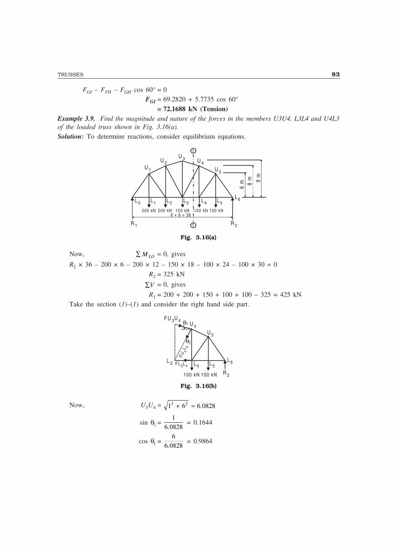
TRUSSES 83
FGI – FFH – FGH cos 60° = 0FGI = 69.2820 + 5.7735 cos 60°
= 72.1688 kN (Tension)Example 3.9. Find the magnitude and nature of the forces in the members U3U4, L3L4 and U4L3of the loaded truss shown in Fig. 3.16(a).
Solution: To determine reactions, consider equilibrium equations.
R 1 R 2
L 6L 5L 4L3L 2L 1L 0
U 1
U 2U 3 U 4
U 5
200 kN 200 kN 150 kN 100 kN 100 kN
6 m 8
m 9 m
1
1
6 × 6 = 36
Fig. 3.16(a)
Now, ∑ M LO = 0, gives
R2 × 36 – 200 × 6 – 200 × 12 – 150 × 18 – 100 × 24 – 100 × 30 = 0
R2 = 325 kN
∑V = 0, gives
R1 = 200 + 200 + 150 + 100 + 100 – 325 = 425 kNTake the section (1)–(1) and consider the right hand side part.
R 2
L 6L 5L4L 3
F U 3U 4
U 5
θ1
θ2
U 4
FUL
43
100 kN 100 kN
FL L3 4
Fig. 3.16(b)
Now, U3U4 = 1 6 6 08282 2+ = .
sin θl =1
6 0828. = 0.1644
cos θl =6
6 0828. = 0.9864
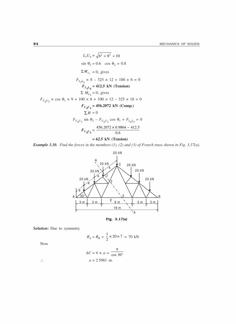
84 MECHANICS OF SOLIDS
L3U4 = 6 8 102 2+ =
sin θ2 = 0.6 cos θ2 = 0.8
4UMΣ = 0, gives
FL3L4 × 8 – 325 × 12 + 100 × 6 = 0
FL3L4= 412.5 kN (Tension)
Σ ML3= 0, gives
FU4U3 × cos θ1 × 9 + 100 × 6 + 100 × 12 – 325 × 18 = 0
FU4U3= 456.2072 kN (Comp.)
∑ H = 0
FU4U3 sin θ2 – FU4U3
cos θ1 + FL4L3 = 0
FU4U3=
456 2072 0 9864 412 5
0 6
. × . .
.
−
= 62.5 kN (Tension)Example 3.10. Find the forces in the members (1), (2) and (3) of French truss shown in Fig. 3.17(a).
a
a
a
a20 kN
20 kN
20 kN
20 kN
20 kN
20 kN
20 kN
BA 30°
1
2
3
3 m 3 m 6 m 3 m 3 m
18 mA
AC
E
Fig. 3.17(a)
Solution: Due to symmetry
RA = RB = 1
220 7× × = 70 kN
Now
AC = 4 × a = 9
30cos °∴ a = 2.5981 m.

TRUSSES 85
2 0 kN
2 0 kN
2 0 kN
θ
C
D F 3 E
F 1
F 2
R A = 7 0 kN
Fig. 3.17(b)
Take Section (A)–(A) and consider the equilibrium of left hand side part of the French Trussshown in Fig. 3.17(b).
Drop perpendicular CE on AB.
Now CE = 9 tan 30° and DE = 3 m
∴ tan θ =9 30
33
1
33
tan×
°= =
∴ θθθθθ = 60°
∑ M A = 0, gives
F2 sin 60° × 6 – 20 × 2.5981 cos 30° – 20 × 2 × 2.5981 cos 30° – 20 × 3 × 2.5981 cos 30° = 0
F2 = 20 × 2.5981 ( )1 2 3
6
+ + since sin 60° = cos 30°
F2 = 51.9615 kN (Tension)
∑V = 0, gives
F1 sin 30° – 70 + 20 + 20 + 20 – 51.9615 sin 60° = 0F1 = 110 kN (Comp.)
∑ H = 0, gives
F3 + F2 cos 60° – F1 cos 30° = 0
F3 = 69.2820 (Tension)Note: In this problem, the method of joints cannot give complete solution.
Example 3.11. Find the forces in all the members of the truss shown in Fig. 3.18(a).
4 5 °3 0 °
a
a
1 HA E
G D
15°
3 0 kN
3 0 kN
1 5 kN 1 5 kN
3 0 kNC
BF
1 0 m
1
Fig. 3.18(a)
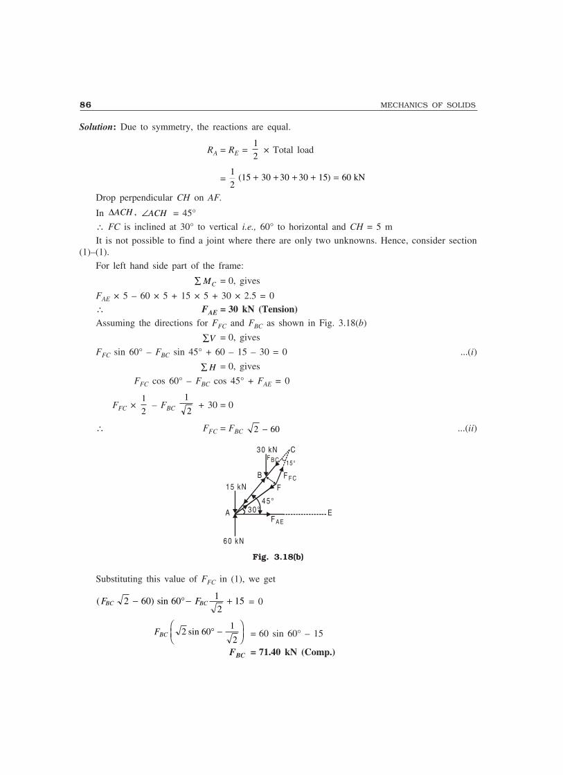
86 MECHANICS OF SOLIDS
Solution: Due to symmetry, the reactions are equal.
RA = RE = 1
2 × Total load
=1
215 30 30 30 15 60( )+ + + + = kN
Drop perpendicular CH on AF.
In ∆ACH , ∠ACH = 45°
∴ FC is inclined at 30° to vertical i.e., 60° to horizontal and CH = 5 m
It is not possible to find a joint where there are only two unknowns. Hence, consider section(1)–(1).
For left hand side part of the frame:
∑ MC = 0, gives
FAE × 5 – 60 × 5 + 15 × 5 + 30 × 2.5 = 0∴ FAE = 30 kN (Tension)Assuming the directions for FFC and FBC as shown in Fig. 3.18(b)
∑V = 0, gives
FFC sin 60° – FBC sin 45° + 60 – 15 – 30 = 0 ...(i)
∑ H = 0, gives
FFC cos 60° – FBC cos 45° + FAE = 0
FFC × 1
2 – FBC
1
2 + 30 = 0
∴ FFC = FBC 2 60− ...(ii)
4 5 °3 0 °
FAEA
15°
3 0 kN
1 5 kNB
F
C
6 0 kN
F F C
E
F BC
Fig. 3.18(b)
Substituting this value of FFC in (1), we get
( ) sinF FBC BC2 60 60 12
15− °− + = 0
FBC 2 601
2sin ° −
���
��� = 60 sin 60° – 15
FBC = 71.40 kN (Comp.)
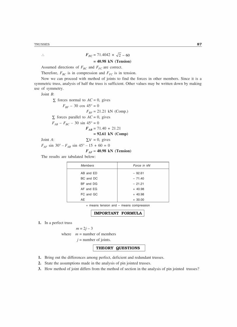
TRUSSES 87
∴ FFC = 71.4042 × 2 60−= 40.98 kN (Tension)
Assumed directions of FBC and FFC are correct.
Therefore, FBC is in compression and FFC is in tension.Now we can proceed with method of joints to find the forces in other members. Since it is a
symmetric truss, analysis of half the truss is sufficient. Other values may be written down by makinguse of symmetry.
Joint B:
∑ forces normal to AC = 0, gives
FBF – 30 cos 45° = 0FBF = 21.21 kN (Comp.)
∑ forces parallel to AC = 0, gives
FAB – FBC – 30 sin 45° = 0FAB = 71.40 + 21.21
= 92.61 kN (Comp)Joint A: ∑V = 0, gives
FAF sin 30° – FAB sin 45° – 15 + 60 = 0FAF = 40.98 kN (Tension)
The results are tabulated below:
Members Force in kN
AB and ED – 92.61
BC and DC – 71.40
BF and DG – 21.21
AF and EG + 40.98
FC and GC + 40.98
AE + 30.00
+ means tension and – means compression
IMPORTANT FORMULA
1. In a perfect trussm = 2j – 3
where m = number of members j = number of joints.
THEORY QUESTIONS
1. Bring out the differences among perfect, deficient and redundant trusses.2. State the assumptions made in the analysis of pin jointed trusses.3. How method of joint differs from the method of section in the analysis of pin jointed trusses?

88 MECHANICS OF SOLIDS
PROBLEMS FOR EXERCISE
1 to 17: Determine the forces in all the members of the trusses shown in Fig. 3.19 to 3.35. Indicatethe nature of forces using the convention tension as +ve and compression as –ve.
1.
6 m 6 m
3 m 6 m
4 m
A
F
B
E D
20 kN
Fig. 3.19 (Prob. 1)
[Ans. FAB = +67.5 kN; FBC = +15 kN; FCD = –25 kN; FDE = –30 kN;
FEF = –105 kN; FAE = +62.5 kN; FBE = –62.5 kN; FBD = +25 kN]2.
4 m
3 m 3 m 3 mEF
B
C
20 kN
20 kN
A
GD
Fig. 3.20 (Prob. 2)
[Ans. FAB = +82.0738 kN; FBC = +73.866 kN; FCD = 49.2443 kN; FDE = –45 kN;FEF = –45 kN; FFG = –67.5 kN; FBG = – 10.0 kN; FFC = +24.622 kN; FCE = 0; FBF = 10 kN]
3.
3 m 3 m 3 m
D
A
F
G
C
E
100 kN
30°
B
Fig. 3.21 (Prob. 3)
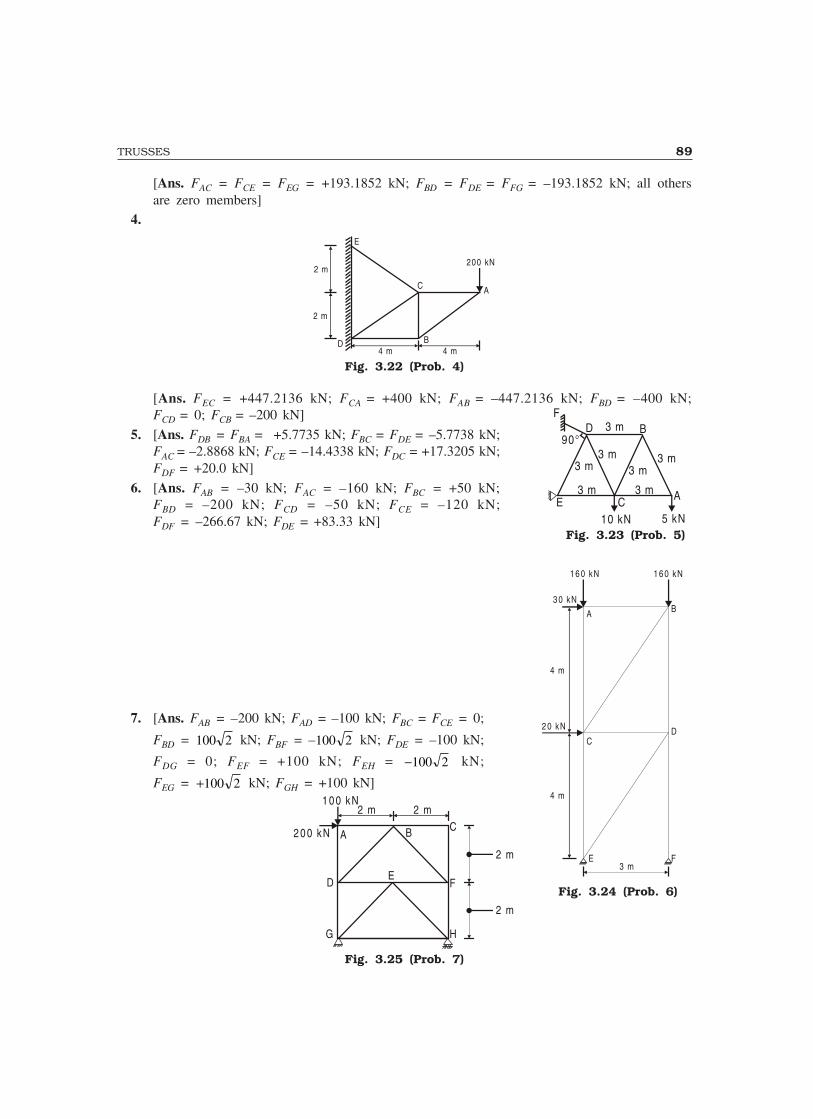
TRUSSES 89
[Ans. FAC = FCE = FEG = +193.1852 kN; FBD = FDE = FFG = –193.1852 kN; all othersare zero members]
4.
E
C A
200 kN
B4 m 4 m
2 m
2 m
D
Fig. 3.22 (Prob. 4)
[Ans. FEC = +447.2136 kN; FCA = +400 kN; FAB = –447.2136 kN; FBD = –400 kN;FCD = 0; FCB = –200 kN]
5. [Ans. FDB = FBA = +5.7735 kN; FBC = FDE = –5.7738 kN;FAC = –2.8868 kN; FCE = –14.4338 kN; FDC = +17.3205 kN;FDF = +20.0 kN]
6. [Ans. FAB = –30 kN; FAC = –160 kN; FBC = +50 kN;FBD = –200 kN; FCD = –50 kN; FCE = –120 kN;FDF = –266.67 kN; FDE = +83.33 kN]
7. [Ans. FAB = –200 kN; FAD = –100 kN; FBC = FCE = 0;
FBD = 100 2 kN; FBF = –100 2 kN; FDE = –100 kN;
FDG = 0; FEF = +100 kN; FEH = −100 2 kN;
FEG = +100 2 kN; FGH = +100 kN]
G H
F
CBA
D
1 0 0 kN2 m 2 m
2 0 0 kN
E
2 m
2 m
Fig. 3.25 (Prob. 7)
Fig. 3.24 (Prob. 6)
1 6 0 kN 1 6 0 kN
3 0 kN
2 0 kN
4 m
4 m
C
3 mE F
D
BA
Fig. 3.23 (Prob. 5)
E C A3 m
3 m3 m3 m
3 m
3 m
BD90°
F3 m
10 kN 5 kN
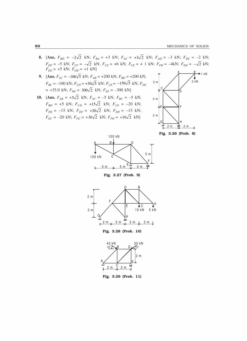
90 MECHANICS OF SOLIDS
8. [Ans. FBD = −2 2 kN; FBA = +3 kN; FAC = +3 2 kN; FAD = –3 kN; FDC = –2 kN;
FDF = –5 kN; FCF = − 2 kN; FCE = +6 kN; FFE = + 1 kN; FFH = –4kN; FEH = − 2 kN;FEG = +5 kN; FGH = +1 kN]
9. [Ans. FAC = –100 5 kN; FAB = +200 kN; FBD = +200 kN;
FBC = –100 kN; FCD = +50 5 kN; FCE = −150 5 kN; FDE
= +35.0 kN; FDF = 300 2 kN; FEF = –300 kN]
10. [Ans. FAB = +5 2 kN; FAC = –5 kN; FBC = –5 kN;
FBD = +5 kN; FCD = +15 2 kN; FCE = –20 kN;
FDE = –15 kN; FDF = +20 2 kN; FEH = –15 kN;
FEF = –20 kN; FFG = +30 2 kN; FFH = +10 2 kN]
5 m 5 m 5 m
FE
DB
C
1 0 0 kN
1 0 0 kN
A
5 m
Fig. 3.27 (Prob. 9)
2 m
2 m
2 m 2 m 2 m 2 m
1 0 kN 5 kN
H
E CA
BD
F
G
Fig. 3.28 (Prob. 10)
2 m
3 0 kNB
A
45° 45°4 0 kN
D
EC2 m 2 m
Fig. 3.29 (Prob. 11)
Fig. 3.26 (Prob. 8)
A B
D
1 kN
2 kN
C
E
G H
F
2 m
2 m
2 m
2 m 2 m
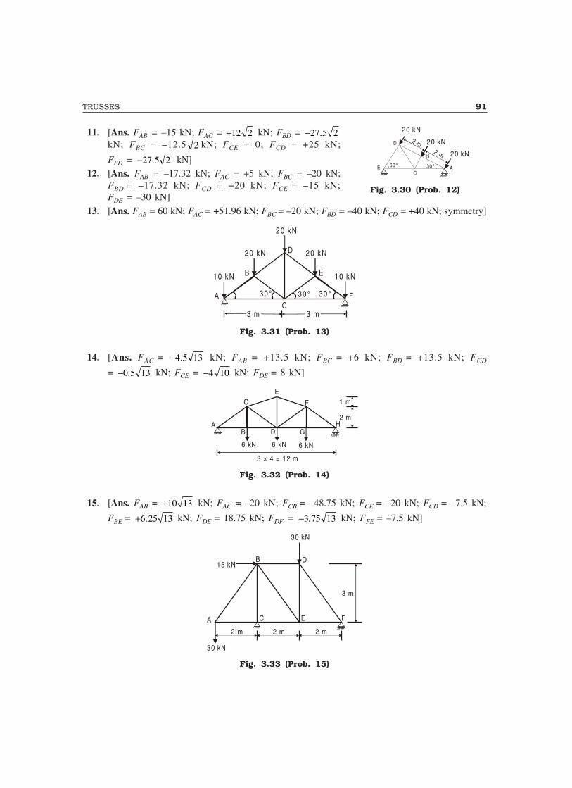
TRUSSES 91
11. [Ans. FAB = –15 kN; FAC = +12 2 kN; FBD = −27 5 2.kN; FBC = –12.5 2 kN; FCE = 0; FCD = +25 kN;
FED = −27 5 2. kN]12. [Ans. FAB = –17.32 kN; FAC = +5 kN; FBC = –20 kN;
FBD = –17.32 kN; FCD = +20 kN; FCE = –15 kN;FDE = –30 kN]
13. [Ans. FAB = 60 kN; FAC = +51.96 kN; FBC = –20 kN; FBD = –40 kN; FCD = +40 kN; symmetry]
3 0 °C
A F
EB
D2 0 kN 2 0 kN
2 0 kN
1 0 kN 1 0 kN
3 m 3 m
3 0 ° 3 0 °
Fig. 3.31 (Prob. 13)
14. [Ans. FAC = −4 5 13. kN; FAB = +13.5 kN; FBC = +6 kN; FBD = +13.5 kN; FCD
= −0 5 13. kN; FCE = −4 10 kN; FDE = 8 kN]
1 m
2 mH
F
EC
AB D G
6 kN 6 kN 6 kN
3 × 4 = 12 m
Fig. 3.32 (Prob. 14)
15. [Ans. FAB = +10 13 kN; FAC = –20 kN; FCB = –48.75 kN; FCE = –20 kN; FCD = –7.5 kN;
FBE = +6 25 13. kN; FDE = 18.75 kN; FDF = −3 75 13. kN; FFE = –7.5 kN]
3 m
2 m 2 m
30 kN
A C E F
DB
30 kN
15 kN
2 m
Fig. 3.33 (Prob. 15)
Fig. 3.30 (Prob. 12)
20 kN
20 kN
20 kN2 m
2 m
30 °60 °EC
A
D
B

92 MECHANICS OF SOLIDS
16. [Ans. FAB = 16.91 kN; FAF = +31.55 kN; FBF = +23.91 kN; FBD = –23.91 kN; FBC = +40 kN;FCD = –40 kN; FDE = –63.1 kN; FDF = +23.91 kN; FEF = +31.55 kN]
3 m 3 m
60°60°60°
A
B D
E
C 40 kN
F
60° 60°
40 kN
Fig. 3.34 (Prob. 16)
17. [Ans. FAC = –67.48 kN; FAB = +53.99 kN; FBC = +10 kN; FCD = –8.33 kN; FCE = –59.15 kN;FEF = –24.5 kN; FED = +52.81 kN; FFD = +47.21 kN; FFG = –34.64 kN;FDG = +47.32 kN]
G
D B A
C
E
F
30°
1.5
m 3 m
30 kN
3 m2 m3 m
10 kN
Fig. 3.35 (Prob. 17)
18. Find the force in the member FG of the triangular Howe truss shown in Fig. 3.36.
A
B
C E G H K
HD
F
J
L
4.5 m
4 kN
8 kN
8 kN
4 kN
6 kN6 kN6 kN6 kN6 kN
1
1
2 m 2 m 2 m 2 m 2 m
Fig. 3.36
(Hint: Take section (1)–(1) and find force in FD. Then analyse joint F) [Ans. +28 kN]
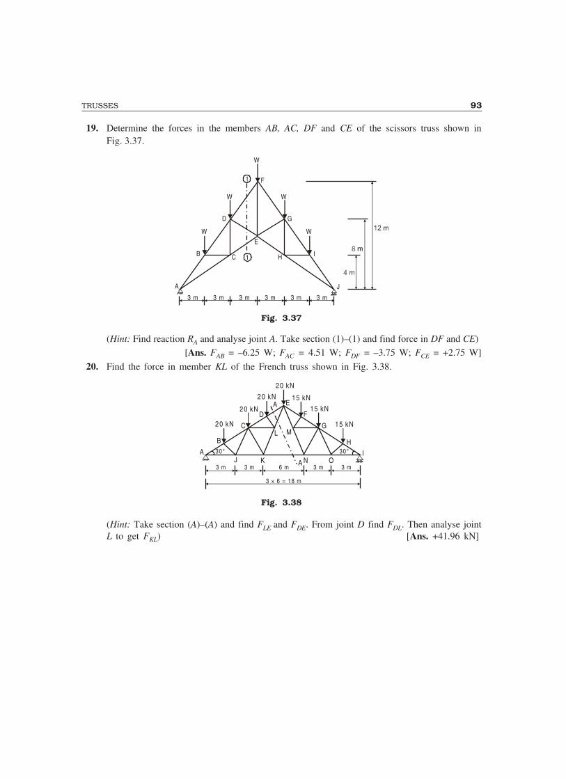
TRUSSES 93
19. Determine the forces in the members AB, AC, DF and CE of the scissors truss shown inFig. 3.37.
1
1
A
B
W
D
W W
W
C
E
H
F
W
G
I
J
3 m 3 m 3 m 3 m 3 m 3 m
Fig. 3.37
(Hint: Find reaction RA and analyse joint A. Take section (1)–(1) and find force in DF and CE)
[Ans. FAB = –6.25 W; FAC = 4.51 W; FDF = –3.75 W; FCE = +2.75 W]
20. Find the force in member KL of the French truss shown in Fig. 3.38.
30° 30°A
B
20 kN
20 kN
20 kN
20 kN
15 kN
15 kN
15 kNC
DA E
F
G
H
A3 m 3 m 6 m 3 m 3 m
3 × 6 = 18 m
IJ K N O
L M
Fig. 3.38
(Hint: Take section (A)–(A) and find FLE and FDE. From joint D find FDL. Then analyse jointL to get FKL) [Ans. +41.96 kN]

4Distributed Forces, Centre of
Gravity and Moment of Inertia
The term ‘distributed force’ has been explained in Art 2.11 and this applied force has been classifiedinto linear surface and the body force. The number of such forces acting on a body is infinite.However, these forces can be replaced by their resultant which acts through a point, known as thecentre of gravity of the body. In this chapter the method of finding areas of given figures andvolumes is explained. Then the terms centroid and centre of gravity and second moment of area(moment of inertia of areas) are explained and method of finding them is illustrated with examples.Theorem of Pappus-Guldinus is introduced which is very useful for finding surface areas and volumesof solids then the method of finding centre of gravity and moment of inertia (mass moment of inertia)of solids is illustrated.
4.1 DETERMINATION OF AREAS AND VOLUMES
In the school education methods of finding areas and volumes of simple cases are taught by manymethods. Here we will see the general approach which is common to all cases i.e. by the method ofintegration. In this method the expression for an elemental area will be written then suitable integra-tions are carried out so as to take care of entire surface/volume. This method is illustrated withstandard cases below, first for finding the areas and latter for finding the volumes:
A: Area of Standard Figures
(i) Area of a rectangleLet the size of rectangle be b × d as shown in Fig. 4.1. dA is an elemental area of side dx × dy.
Area of rectangle, A = ��dA =/ 2 / 2
/ 2 / 2
b d
b d� �� � dx dy
= [x] / 2/ 2
bb� [y] / 2
/ 2d
d�
= bd.If we take element as shown in Fig. 4.2,
Fig. 4.194
d/2
d/2
b/2 b/2
O
y
dxdy
x
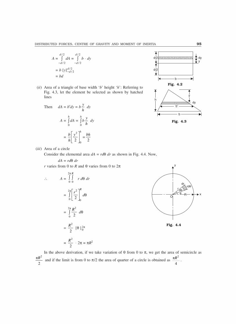
DISTRIBUTED FORCES, CENTRE OF GRAVITY AND MOMENT OF INERTIA 95
A =/ 2
/ 2
d
d�� dA =
/ 2
/ 2
d
d�� b ⋅ dy
= b [y] / 2/ 2
dd�
= bd
(ii) Area of a triangle of base width ‘b’ height ‘h’: Referring toFig. 4.3, let the element be selected as shown by hatchedlines
Then dA = b′dy = by
h dy
A = 0
h
� dA = 0
h
� by
h dy
= 2
02 2
hb y bh
h
� ��� �
�
(iii) Area of a circleConsider the elemental area dA = rdθ�dr as shown in Fig. 4.4. Now,
dA = rdθ drr varies from 0 to R and θ varies from 0 to 2π
∴ A = 2�
0 0
R
� � r dθ dr
= 22�
0 02
Rr� �
� ��
� dθ
= 22�
0 2
R� dθ
= 2
2
R [θ ] 2�
0
= 2
2
R ⋅2π = πR2
In the above derivation, if we take variation of θ from 0 to π, we get the area of semicircle as2
�
2
R and if the limit is from 0 to π /2 the area of quarter of a circle is obtained as 2
�
4
R .
dyy
d/2
d/2
b
Fig. 4.2
yh
b�dy
b
Fig. 4.3
Fig. 4.4
O
drrd�
d�r
� xRR
y

96 MECHANICS OF SOLIDS
(iv) Area of a sector of a circleArea of a sector of a circle with included angle 2α shown in Fig. 4.5 is to be determined. Theelemental area is as shown in the figure
dA = rdθ ⋅ drθ varies from –α to α�and r varies from 0 to R
∴ A = ��dA = 0
R�
��� � r dθ dr
= 2
02
Rr�
��
� �� ��
� dθ = 2
2
R�
��� dθ
= 2
�2
R�
��
� �� ��
= 2
2
R(2α) = R2α.
(v) Area of a parabolic spandrelTwo types of parabolic curves are possible(a) y = kx2
(b) y2 = kx
Case a: This curve is shown in Fig. 4.6.The area of the element
dA = y dx
= kx2 dx
∴ A = 0
a
� dA = 0
a
� kx2 dx
= k 3 3
03 3
ax ka� �
�� ��
We know, when x = a, y = h
i.e., h = ka2 or k = 2
h
a
∴ A = 3 3
2
1 1rd
3 3 3 3
ka h aha
a� � � the area of rectangle of size a × h
Case b: In this case y2 = kxReferring to Fig. 4.7
dA = y dx = kx dx
A = 0
a
� y dx = 0
a
� kx dx
Fig. 4.5
x
h
x = a
y = kx2
x
dx
y
Fig. 4.6
y
O d��
dr
rd�r
x
R
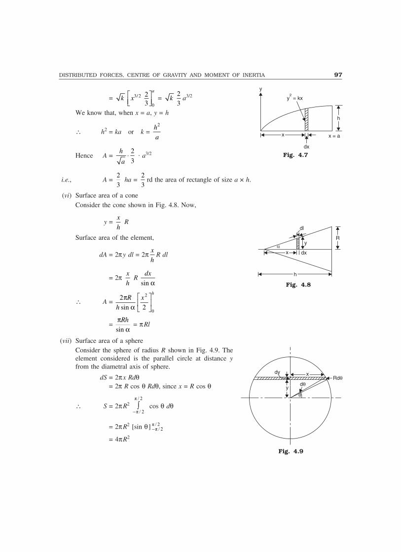
DISTRIBUTED FORCES, CENTRE OF GRAVITY AND MOMENT OF INERTIA 97
= k 3/2
0
23
a
x� �� ��
= k2
3a3/2
We know that, when x = a, y = h
∴ h2 = ka or k = 2h
a
Hence A = 2
3
h
a� . a3/2
i.e., A = 2
3 ha =
2
3rd the area of rectangle of size a × h.
(vi) Surface area of a coneConsider the cone shown in Fig. 4.8. Now,
y = x
h R
Surface area of the element,
dA = 2πy dl = 2π x
hR dl
= 2π x
h R
dx
sin α
∴ A = 2
2
2
0
πα
R
h
xh
sin
�
���
��
= π
αRh
sin = πRl
(vii) Surface area of a sphereConsider the sphere of radius R shown in Fig. 4.9. Theelement considered is the parallel circle at distance yfrom the diametral axis of sphere.
dS = 2πx Rdθ= 2π R cos θ Rdθ, since x = R cos θ
∴ S = 2πR2 � � �
� � ��� cos θ dθ
= 2πR2 [sin θ] � � �� � ��
= 4πR2
y
y = kx2
hh
xx
dx
x = a
Fig. 4.7
dl
y
hh
xx dx
RR
Fig. 4.8
dy xxRd�
yyd�
�
Fig. 4.9
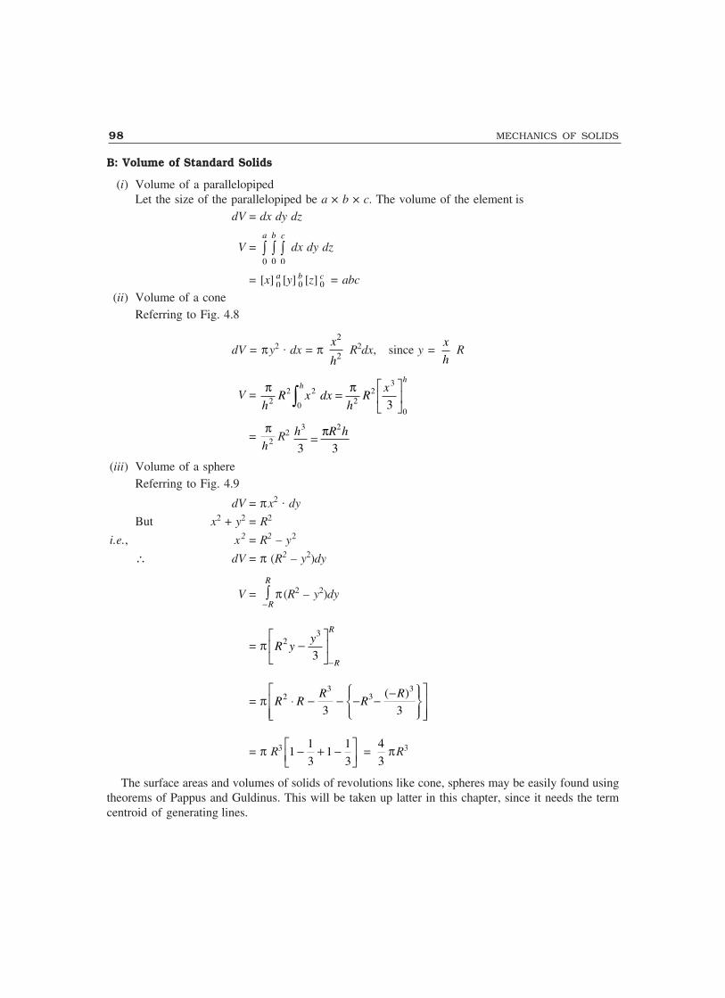
98 MECHANICS OF SOLIDS
B: Volume of Standard Solids
(i) Volume of a parallelopipedLet the size of the parallelopiped be a × b × c. The volume of the element is
dV = dx dy dz
V = 0
a
�0
b
�0
c
� dx dy dz
= [x] 0a [y] 0
b [z] 0c = abc
(ii) Volume of a coneReferring to Fig. 4.8
dV = πy2 . dx = π 2
2
x
h R2dx, since y =
x
h R
V = π πh
R x dxh
Rxh
h
22
0
22
23
03� =�
���
��
= π
h2 R2 h R h3 2
3 3= π
(iii) Volume of a sphereReferring to Fig. 4.9
dV = πx2 . dy
But x2 + y2 = R2
i.e., x2 = R2 – y2
∴ dV = π (R2 – y2)dy
V = R
R�� π (R2 – y2)dy
= π3
2
3
R
R
yR y
�
� ��� �
�
= π3 3
2 3 ( )
3 3
R RR R R
� �� �� �� � � � �� �� �� �� �� ��
= π R3 1 11 1
3 3� �� � �� ��
= 4
3πR3
The surface areas and volumes of solids of revolutions like cone, spheres may be easily found usingtheorems of Pappus and Guldinus. This will be taken up latter in this chapter, since it needs the termcentroid of generating lines.
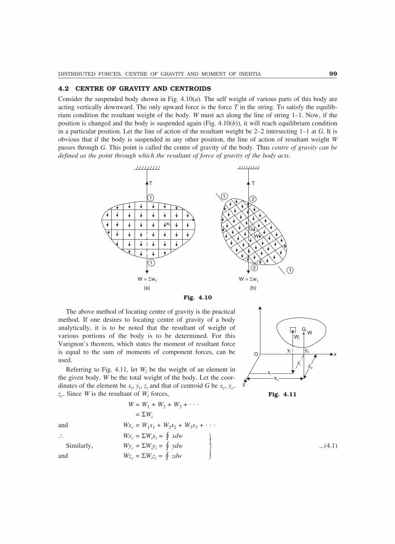
DISTRIBUTED FORCES, CENTRE OF GRAVITY AND MOMENT OF INERTIA 99
4.2 CENTRE OF GRAVITY AND CENTROIDS
Consider the suspended body shown in Fig. 4.10(a). The self weight of various parts of this body areacting vertically downward. The only upward force is the force T in the string. To satisfy the equilib-rium condition the resultant weight of the body. W must act along the line of string 1–1. Now, if theposition is changed and the body is suspended again (Fig. 4.10(b)), it will reach equilibrium conditionin a particular position. Let the line of action of the resultant weight be 2–2 intersecting 1–1 at G. It isobvious that if the body is suspended in any other position, the line of action of resultant weight Wpasses through G. This point is called the centre of gravity of the body. Thus centre of gravity can bedefined as the point through which the resultant of force of gravity of the body acts.
T
1
1
1 2
2 1
GW
W = w� 1 W = w� 1
w1
T
(a) (b)
Fig. 4.10
The above method of locating centre of gravity is the practicalmethod. If one desires to locating centre of gravity of a bodyanalytically, it is to be noted that the resultant of weight ofvarious portions of the body is to be determined. For thisVarignon’s theorem, which states the moment of resultant forceis equal to the sum of moments of component forces, can beused.
Referring to Fig. 4.11, let Wi be the weight of an element inthe given body. W be the total weight of the body. Let the coor-dinates of the element be xi, yi, zi and that of centroid G be xc, yc,zc. Since W is the resultant of Wi forces,
W = W1 + W2 + W3 + . . .
= ΣWi
and Wxc = W1x1 + W2x2 + W3x3 + . . .
∴ Wxc = ΣWixi = �� xdw
Similarly, Wyc = ΣWiyi = �� ydw�����
...(4.1)
and Wzc = ΣWizi = �� zdw
Fig. 4.11
Wi
GW
yi yc xO
zizi zczc
xixixcxc
z
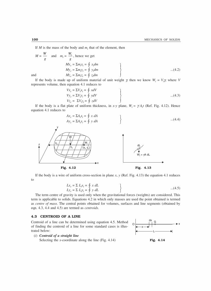
100 MECHANICS OF SOLIDS
If M is the mass of the body and mi that of the element, then
M = W
gand mi = iW
g, hence we get
Mxc = Σmixi = �� xidm
Myc = Σmiyi = �� yidm�����
...(4.2)
and Mzc = Σmizi = �� zidm
If the body is made up of uniform material of unit weight �, then we know Wi = Vi�, where Vrepresents volume, then equation 4.1 reduces to
Vxc = ΣVixi = �� xdV
Vyc = ΣViyi = �� ydV�����
...(4.3)
Vzc = ΣVizi = �� zdVIf the body is a flat plate of uniform thickness, in x-y plane, Wi = � Ait (Ref. Fig. 4.12). Hence
equation 4.1 reduces to
Axc = ΣAixi = �� x dA
Ayc = ΣAiyi = �� y dA���
...(4.4)
y
z
W
xc
yc
Wi
(x , y )i c(x , y )i c
x
dL
W = A dLi �
Fig. 4.12 Fig. 4.13
If the body is a wire of uniform cross-section in plane x, y (Ref. Fig. 4.13) the equation 4.1 reducesto
Lxc = Σ Lixi = �� x dLLyc = Σ Liyi = �� y dL
���
...(4.5)
The term centre of gravity is used only when the gravitational forces (weights) are considered. Thisterm is applicable to solids. Equations 4.2 in which only masses are used the point obtained is termedas centre of mass. The central points obtained for volumes, surfaces and line segments (obtained byeqn. 4.3, 4.4 and 4.5) are termed as centroids.
4.3 CENTROID OF A LINE
Centroid of a line can be determined using equation 4.5. Methodof finding the centroid of a line for some standard cases is illus-trated below:
(i) Centroid of a straight lineSelecting the x-coordinate along the line (Fig. 4.14)
dx G
xx
LL
O x
Fig. 4.14
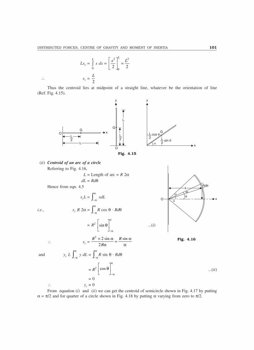
DISTRIBUTED FORCES, CENTRE OF GRAVITY AND MOMENT OF INERTIA 101
Lxc = 0
L
� x dx = 2 2
02 2
Lx L� �
�� ��
∴ xc = 2
L
Thus the centroid lies at midpoint of a straight line, whatever be the orientation of line(Ref. Fig. 4.15).
GO
L2L2
LL
x
y
G
LL
L2L2
O
y
L2L2
cos �cos �G
L2L2
sin �sin �
x
Fig. 4.15
(ii) Centroid of an arc of a circleReferring to Fig. 4.16,
L = Length of arc = R 2αdL = Rdθ
Hence from eqn. 4.5
xcL = −� α
α xdL
i.e., xc R 2α = −� α
αR cos θ . Rdθ
= R2 sin θα
α�
��
�
��
−
...(i)
∴ xc = R
R
R2 2
2
× =sin sinαα
αα
and yc L −� α
α y dL =
−� α
αR sin θ . Rdθ
= R2 cos θα
α�
��
�
��
−...(ii)
= 0∴ yc = 0From equation (i) and (ii) we can get the centroid of semicircle shown in Fig. 4.17 by putting
α = π/2 and for quarter of a circle shown in Fig. 4.18 by putting α varying from zero to π/2.
Rd�
O
d�
�x
xx
Fig. 4.16
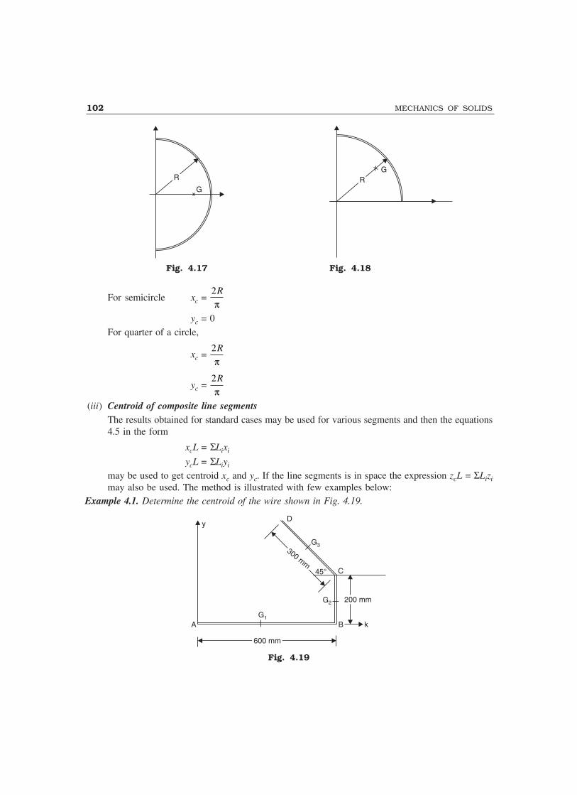
102 MECHANICS OF SOLIDS
RR
G
GRR
Fig. 4.17 Fig. 4.18
For semicircle xc = 2R
πyc = 0
For quarter of a circle,
xc = 2R
π
yc = 2R
π(iii) Centroid of composite line segments
The results obtained for standard cases may be used for various segments and then the equations4.5 in the form
xcL = ΣLixi
ycL = ΣLiyi
may be used to get centroid xc and yc. If the line segments is in space the expression zcL = ΣLizimay also be used. The method is illustrated with few examples below:
Example 4.1. Determine the centroid of the wire shown in Fig. 4.19.
yD
G3
C45°
G1
A B k
G2 200 mm200 mm
300 mm
300 mm
600 mm600 mm
Fig. 4.19

DISTRIBUTED FORCES, CENTRE OF GRAVITY AND MOMENT OF INERTIA 103
Solution: The wire is divided into three segments AB, BC and CD. Taking A as origin the coordinatesof the centroids of AB, BC and CD are
G1(300, 0); G2(600, 100) and G3 (600 – 150 cos 45°, 200 + 150 sin 45°)
i.e., G3 (493.93, 306.07)
L1 = 600 mm, L2 = 200 mm, L3 = 300 mm∴ Total length L = 600 + 200 + 300 = 1100 mm
∴ From the eqn. Lxc = ΣLixi, we get
1100 xc = L1x1 + L2x2 + L3x3
= 600 × 300 + 200 × 600 + 300 × 493.93
∴ xc = 407.44 mm
Now, Lyc = ΣLiyi
1100 yc = 600 × 0 + 200 × 100 + 300 × 306.07
∴ yc = 101.66 mmExample 4.2. Locate the centroid of the uniform wire bent as shown in Fig. 4.20.
AG1
G2150 mm150 mm
250 mm250 mm
30°G3
D
B
400 mm400 mmC
All dimensions in mm
Fig. 4.20
Solution: The composite figure is divided into three simple figures and taking A as origin coordinatesof their centroids noted down as shown below:
AB—a straight lineL1 = 400 mm, G1 (200, 0)
BC—a semicircle
L2 = 150 π = 471.24, G2 4752 150
,�
�π
i.e. G2 (475, 95.49)CD—a straight line
L3 = 250; x3 = 400 + 300 + 250
2 cos 30° = 808.25 mm
y3 = 125 sin 30° = 62.5 mm∴ Total length L = L1 + L2 + L3 = 1121.24 mm
∴ Lxc = ΣLixi gives
1121.24 xc = 400 × 200 + 471.24 × 475 + 250 × 808.25
xc = 451.20 mm
Lyc = ΣLiyi gives

104 MECHANICS OF SOLIDS
1121.24 yc = 400 × 0 + 471.24 × 95.49 + 250 × 62.5
yc = 54.07 mmExample 4.3. Locate the centroid of uniform wire shown in Fig. 4.21. Note: portion AB is in x-z plane,BC in y-z plane and CD in x-y plane. AB and BC are semi circular in shape.
r =10
0
r =10
0r = 140r = 140
z
yC 45°
Ax
D
B
Fig. 4.21
Solution: The length and the centroid of portions AB, BC and CD are as shown in table below:
Table 4.1
Portion Li xi yi zi
AB 100π 100 02 100×
π
BC 140π 0 1402 140×
πCD 300 300 sin 45° 280 + 300 cos 45°
= 492.13 0
∴ L = 100π + 140π + 300 = 1053.98 mm
From eqn. Lxc = ΣLixi, we get
1053.98 xc = 100π × 100 + 140π × 0 + 300 × 300 sin 45°
xc = 90.19 mm
Similarly, 1053.98 yc = 100π × 0 + 140π × 140 + 300 × 492.13
yc = 198.50 mm
and 1053.98 zc = 100π × 200
π + 140π ×
2 140×π
+ 300 × 0
zc = 56.17 mm
4.4 FIRST MOMENT OF AREA AND CENTROID
From equation 4.1, we have
xc = i iW x
W
�, yc = i iW y
W
�and zc = i iW z
W
�
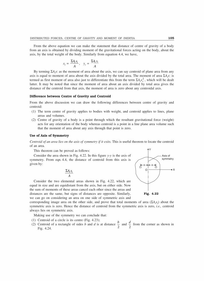
DISTRIBUTED FORCES, CENTRE OF GRAVITY AND MOMENT OF INERTIA 105
From the above equation we can make the statement that distance of centre of gravity of a bodyfrom an axis is obtained by dividing moment of the gravitational forces acting on the body, about theaxis, by the total weight of the body. Similarly from equation 4.4, we have,
xc = i iA x
A
�, yc = i iA y
A
�
By terming ΣAix: as the moment of area about the axis, we can say centroid of plane area from anyaxis is equal to moment of area about the axis divided by the total area. The moment of area ΣAix: istermed as first moment of area also just to differentiate this from the term ΣAix
2i , which will be dealt
latter. It may be noted that since the moment of area about an axis divided by total area gives thedistance of the centroid from that axis, the moment of area is zero about any centroidal axis.
Difference between Centre of Gravity and Centroid
From the above discussion we can draw the following differences between centre of gravity andcentroid:
(1) The term centre of gravity applies to bodies with weight, and centroid applies to lines, planeareas and volumes.
(2) Centre of gravity of a body is a point through which the resultant gravitational force (weight)acts for any orientation of the body whereas centroid is a point in a line plane area volume suchthat the moment of area about any axis through that point is zero.
Use of Axis of Symmetry
Centroid of an area lies on the axis of symmetry if it exits. This is useful theorem to locate the centroidof an area.
This theorem can be proved as follows:Consider the area shown in Fig. 4.22. In this figure y-y is the axis of
symmetry. From eqn. 4.4, the distance of centroid from this axis isgiven by:
i iA x
A
�
Consider the two elemental areas shown in Fig. 4.22, which areequal in size and are equidistant from the axis, but on either side. Nowthe sum of moments of these areas cancel each other since the areas anddistances are the same, but signs of distances are opposite. Similarly,we can go on considering an area on one side of symmetric axis andcorresponding image area on the other side, and prove that total moments of area (ΣAixi) about thesymmetric axis is zero. Hence the distance of centroid from the symmetric axis is zero, i.e., centroidalways lies on symmetric axis.
Making use of the symmetry we can conclude that:(1) Centroid of a circle is its centre (Fig. 4.23);(2) Centroid of a rectangle of sides b and d is at distance
2
b and
2
d from the corner as shown in
Fig. 4.24.
Y
Axis ofsymmetry
xx xx
XO
Fig. 4.22

106 MECHANICS OF SOLIDS
G
b/2b/2bb
dd
d/2d/2
G
Fig. 4.23 Fig. 4.24
Determination of Centroid of Simple Figures From First Principle
For simple figures like triangle and semicircle, we can write general expression for the elemental areaand its distance from an axis. Then equation 4.4 reduces to:
y = ydA
A�
x = xdA
A�
The location of the centroid using the above equations may be considered as finding centroid fromfirst principle. Now, let us find centroid of some standard figures from first principle.
Centroid of a Triangle
Consider the triangle ABC of base width b and height h as shown in Fig. 4.25. Let us locate thedistance of centroid from the base. Let b1 be the width of elemental strip of thickness dy at a distancey from the base. Since �AEF and �ABC are similar triangles, we can write:
1b
b=
h y
h
�
b1 = h y
h
�� �� �� �
b = 1y
h� ��� �� �
b
∴ Area of the element= dA = b1dy
= 1y
h� ��� �� �
b dy
Area of the triangle A = 1
2bh
∴ From eqn. 4.4
y = Moment of area
Total area
ydA
A� �
Now, � ydA = 0
h
� y 1y
h� ��� �� �
b dy
A
E
B
dy
Fb1b1
bbC
hhyy
Fig. 4.25
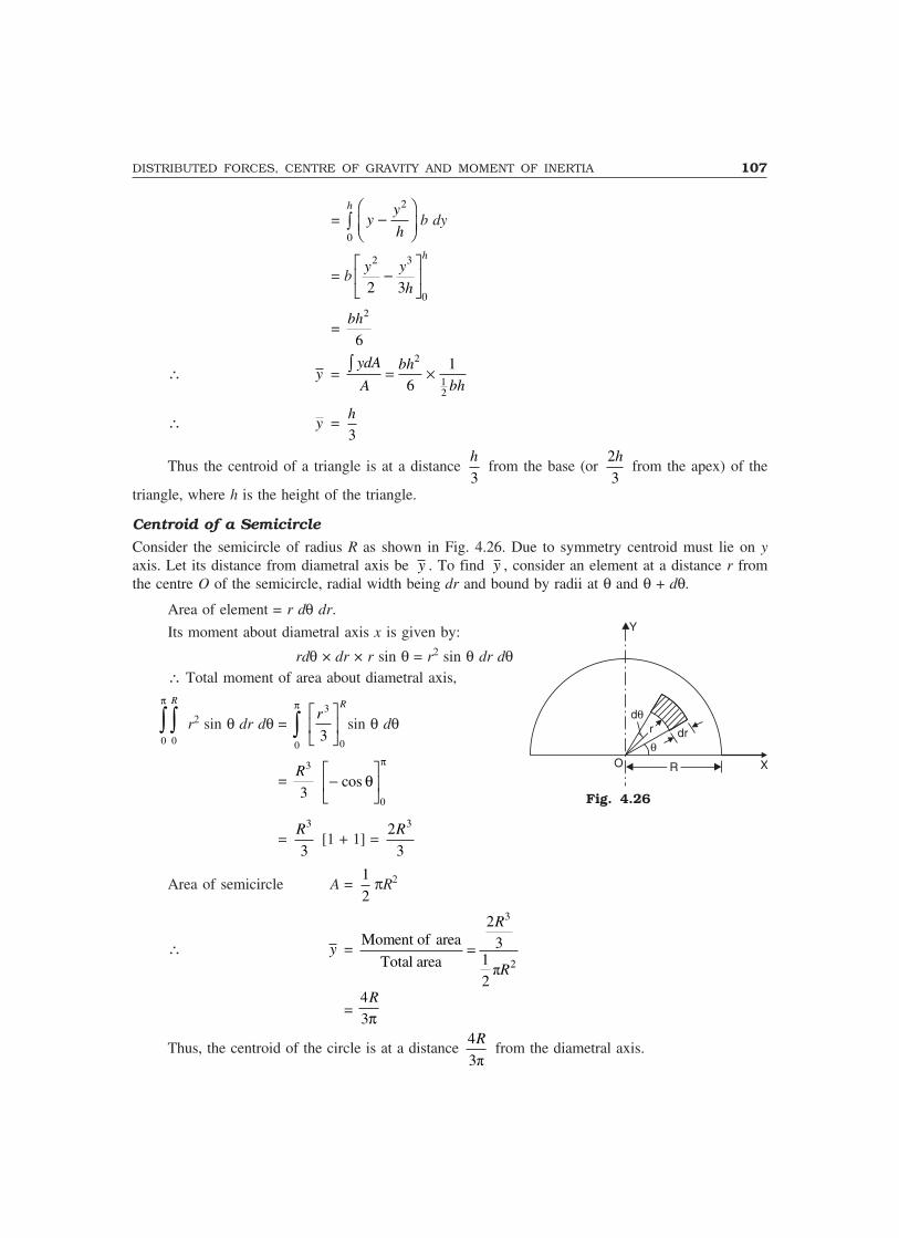
DISTRIBUTED FORCES, CENTRE OF GRAVITY AND MOMENT OF INERTIA 107
=0
h
�2y
yh
� ��� �� �
b dy
= b2 3
02 3
hy y
h
� ��� �
�
=2
6
bh
∴ y =2
12
16
ydA bh
A bh� ��
∴ y =3
h
Thus the centroid of a triangle is at a distance 3
h from the base (or
2
3
h from the apex) of the
triangle, where h is the height of the triangle.
Centroid of a Semicircle
Consider the semicircle of radius R as shown in Fig. 4.26. Due to symmetry centroid must lie on yaxis. Let its distance from diametral axis be y . To find y , consider an element at a distance r fromthe centre O of the semicircle, radial width being dr and bound by radii at θ and θ + dθ.
Area of element = r dθ�dr.
Its moment about diametral axis x is given by:
rdθ × dr × r sin θ = r2 sin θ dr dθ∴ Total moment of area about diametral axis,
00
R
��π
r2 sin θ dr dθ = 0
3
03
π
��
���
��
rR
sin θ dθ
= 3
3
R −�
��
�
��cos θ
π
0
= 3
3
R [1 + 1] =
32
3
R
Area of semicircle A = 1
2πR2
∴ y =
3
2
2Moment of area 3
1Total area�
2
R
R�
= 4
3
R
π
Thus, the centroid of the circle is at a distance 4
3�
R from the diametral axis.
d�rr
�dr
O X
Y
RR
Fig. 4.26
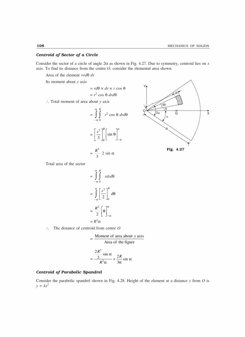
108 MECHANICS OF SOLIDS
Centroid of Sector of a Circle
Consider the sector of a circle of angle 2α as shown in Fig. 4.27. Due to symmetry, centroid lies on xaxis. To find its distance from the centre O, consider the elemental area shown.
Area of the element =rdθ dr
Its moment about y axis
= rdθ × dr × r cos θ= r2 cos θ drdθ
∴ Total moment of area about y axis
=0
R
��− α
α
r2 cos θ drdθ
=3
03
Rr� �
� ��
sin θα
α�
��
�
��
−
=3
3
R 2 sin α
Total area of the sector
=0
R
��− α
α
rdrdθ
=−��
���
��
α
α
θrd
R2
02
=2
2
Rθ
α
α������−
= R2α� The distance of centroid from centre O
=Moment of area about axis
Area of the figure
y
=
2
3 2
3
3
2
R
R
Rsinsin
α
α αα=
Centroid of Parabolic Spandrel
Consider the parabolic spandrel shown in Fig. 4.28. Height of the element at a distance x from O isy = kx2
Y
X
dr
d��
rr
2
O
RR
G
Fig. 4.27

DISTRIBUTED FORCES, CENTRE OF GRAVITY AND MOMENT OF INERTIA 109
Width of element = dx
∴ Area of the element = kx2dx
∴ Total area of spandrel =0
a
� kx2dx = 3
03
akx� �
� ��
=3
3
ka
Moment of area about y axis
=0
a
� kx2dx × x
=0
a
� kx3 dx
=4
04
ak x� �
� ��
=4
4
ka
Moment of area about x axis = dAya
.20�
=0
a
� kx2dx 2 2 4
02 2
akx k x� � dx
=2 5
10
k a
∴ x =4 3 3
4 3 4
ka ka a� �
y =2 5 3 3
10 3 10
k a ka� � ka2
From the Fig. 4.28, at x = a, y = h
∴ h = ka2 or k = 2
h
a
∴ y = 22
3 3
10 10
h ha
a� �
Thus, centroid of spandrel is 3 3
,4 10
a h� �� �� �
Centroids of some common figures are shown in Table 4.2.
y = kx2Y
O xxdx
aa
hh
X
– –G(x, y)
Fig. 4.28
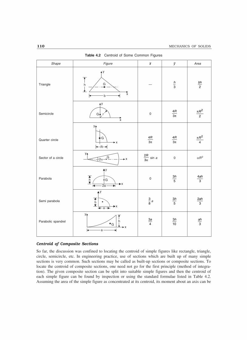
110 MECHANICS OF SOLIDS
Table 4.2 Centroid of Some Common Figures
Shape Figure x y Area
Triangle
y
x
hh G
bb
—3h
2bh
Semicircle
y
x
rrG 04
3
Rπ
πR2
2
Quarter circle
y
xRR
G 4
3
Rπ
4
3
Rπ
πR2
4
Sector of a circley
xG22
2
3
Rα
sin a 0 αR 2
Parabola
y
Gx
h
2a
035h 4
3ah
Semi parabola
y
hxa
38
a35h 2
3ah
Parabolic spandrel
y
xaa
Ghh 3
4a 3
10h
3ah
Centroid of Composite Sections
So far, the discussion was confined to locating the centroid of simple figures like rectangle, triangle,circle, semicircle, etc. In engineering practice, use of sections which are built up of many simplesections is very common. Such sections may be called as built-up sections or composite sections. Tolocate the centroid of composite sections, one need not go for the first principle (method of integra-tion). The given composite section can be split into suitable simple figures and then the centroid ofeach simple figure can be found by inspection or using the standard formulae listed in Table 4.2.Assuming the area of the simple figure as concentrated at its centroid, its moment about an axis can be

DISTRIBUTED FORCES, CENTRE OF GRAVITY AND MOMENT OF INERTIA 111
found by multiplying the area with distance of its centroidfrom the reference axis. After determining moment of eacharea about reference axis, the distance of centroid from theaxis is obtained by dividing total moment of area by total areaof the composite section.
Example 4.4. Locate the centroid of the T-section shownin the Fig. 4.29.
Solution: Selecting the axis as shown in Fig. 4.29, wecan say due to symmetry centroid lies on y axis, i.e. x = 0.Now the given T-section may be divided into two rectanglesA1 and A2 each of size 100 × 20 and 20 × 100. The centroid ofA1 and A2 are g1(0, 10) and g2(0, 70) respectively.
∴ The distance of centroid from top is given by:
y = 100 20 10 20 100 70
100 20 20 100
� � � � �� � �
= 40 mmHence, centroid of T-section is on the symmetric axis at a distance 40 mm from the top.Example 4.5. Find the centroid of the unequal angle 200 × 150 × 12 mm, shown in Fig. 4.30.Solution: The given composite figure can be divided into two rectangles:
A1 = 150 × 12 = 1800 mm2
A2 = (200 – 12) × 12 = 2256 mm2
Total area A = A1 + A2 = 4056 mm2
Selecting the reference axis x and y as shown inFig. 4.30. The centroid of A1 is g1 (75, 6) and that of A2 is:
g21
6,12 (200 12)2
� �� �� �� i.e., g2 (6, 106)
∴ x = Moment about axis
Total area
y
= 1 1 2 2A x A x
A
�
= 1800 75 2256 6
4056
� � � = 36.62 mm
y = Moment about axis
Total area
x
= 1 1 2 2A y A y
A
�
= 1800 6 2256 106
4056
� � � = 61.62 mm
Thus, the centroid is at x = 36.62 mm and y = 61.62 mm as shown in the figure.
100100 O
A1 g1–y–y
X20
G
g2
A2
2020
100100
YAll dimensions in mmAll dimensions in mm
Fig. 4.29
Fig. 4.30
150150
X12
A1
O–x
g1–y–y
200200
G
g2
A2
12
YAll dimensions in mm

112 MECHANICS OF SOLIDS
Example 4.6. Locate the centroid of the I-section shown in Fig. 4.31.
Y100100
g1A120
100100
2020
A2
g2
G
3030 A3g3
O150150
X
–y–y
All dimensions in mmAll dimensions in mm
Fig. 4.31
Solution: Selecting the coordinate system as shown in Fig. 4.31, due to symmetry centroid mustlie on y axis,
i.e., x = 0Now, the composite section may be split into three rectangles
A1 = 100 × 20 = 2000 mm2
Centroid of A1 from the origin is:
y1 = 30 + 100 + 20
2 = 140 mm
Similarly A2 = 100 × 20 = 2000 mm2
y2 = 30 + 100
2 = 80 mm
A3 = 150 × 30 = 4500 mm2,
and y3 = 30
2 = 15 mm
∴ y = 1 1 2 2 3 3A y A y A y
A
� �
= 2000 140 2000 80 4500 15
2000 2000 4500
� � � � �� �
= 59.71 mmThus, the centroid is on the symmetric axis at a distance 59.71 mm from the bottom as
shown in Fig. 4.31.
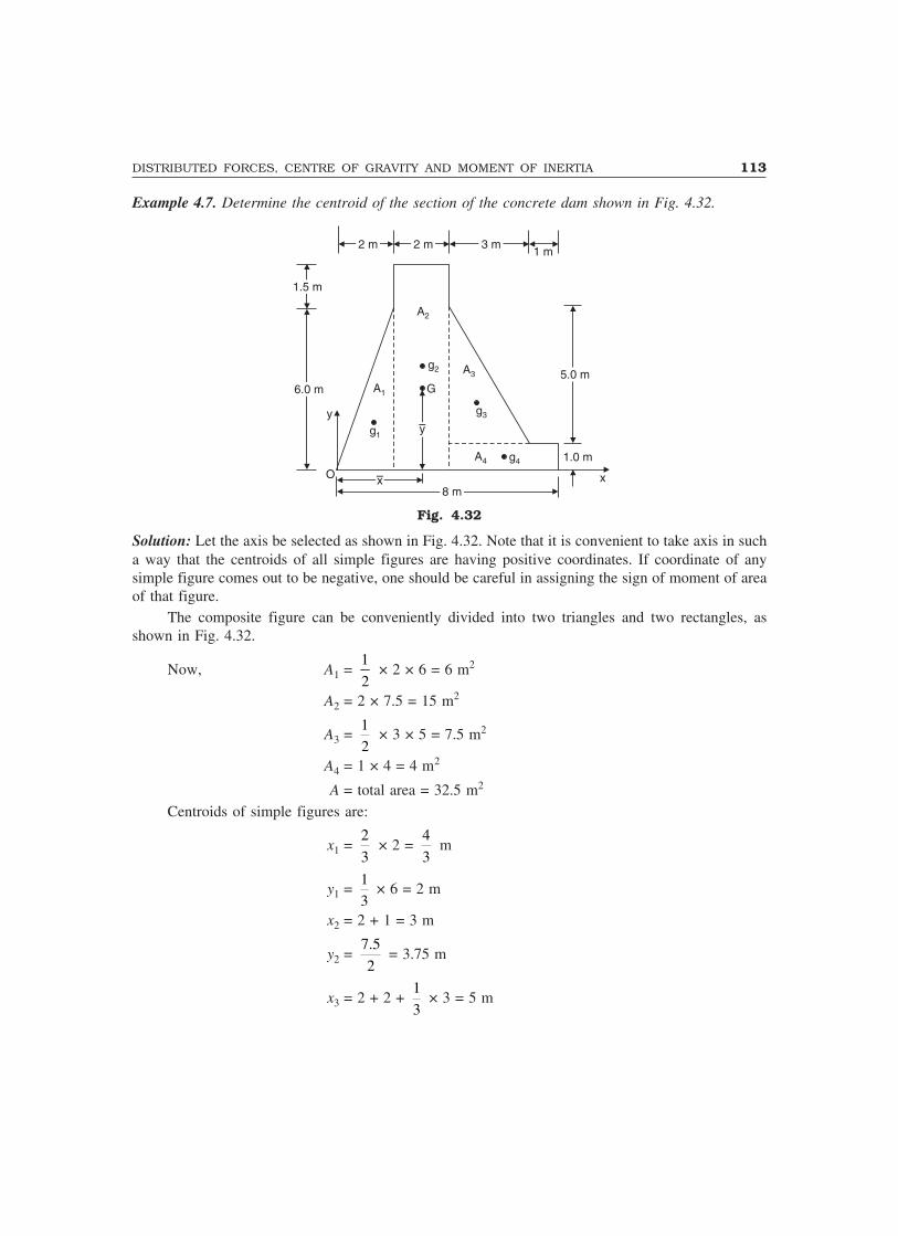
DISTRIBUTED FORCES, CENTRE OF GRAVITY AND MOMENT OF INERTIA 113
Example 4.7. Determine the centroid of the section of the concrete dam shown in Fig. 4.32.
2 m2 m 2 m2 m 3 m3 m1 m
1.5 m1.5 m
6.0 m6.0 m
y
O –x–x8 m8 m
1.0 m
5.0 m5.0 m
A2
A1
g1
G
–y–y
g3
g4A4
A3g2
x
Fig. 4.32
Solution: Let the axis be selected as shown in Fig. 4.32. Note that it is convenient to take axis in sucha way that the centroids of all simple figures are having positive coordinates. If coordinate of anysimple figure comes out to be negative, one should be careful in assigning the sign of moment of areaof that figure.
The composite figure can be conveniently divided into two triangles and two rectangles, asshown in Fig. 4.32.
Now, A1 = 1
2 × 2 × 6 = 6 m2
A2 = 2 × 7.5 = 15 m2
A3 = 1
2 × 3 × 5 = 7.5 m2
A4 = 1 × 4 = 4 m2
A = total area = 32.5 m2
Centroids of simple figures are:
x1 = 2
3 × 2 =
4
3 m
y1 = 1
3 × 6 = 2 m
x2 = 2 + 1 = 3 m
y2 = 7.5
2 = 3.75 m
x3 = 2 + 2 + 1
3 × 3 = 5 m
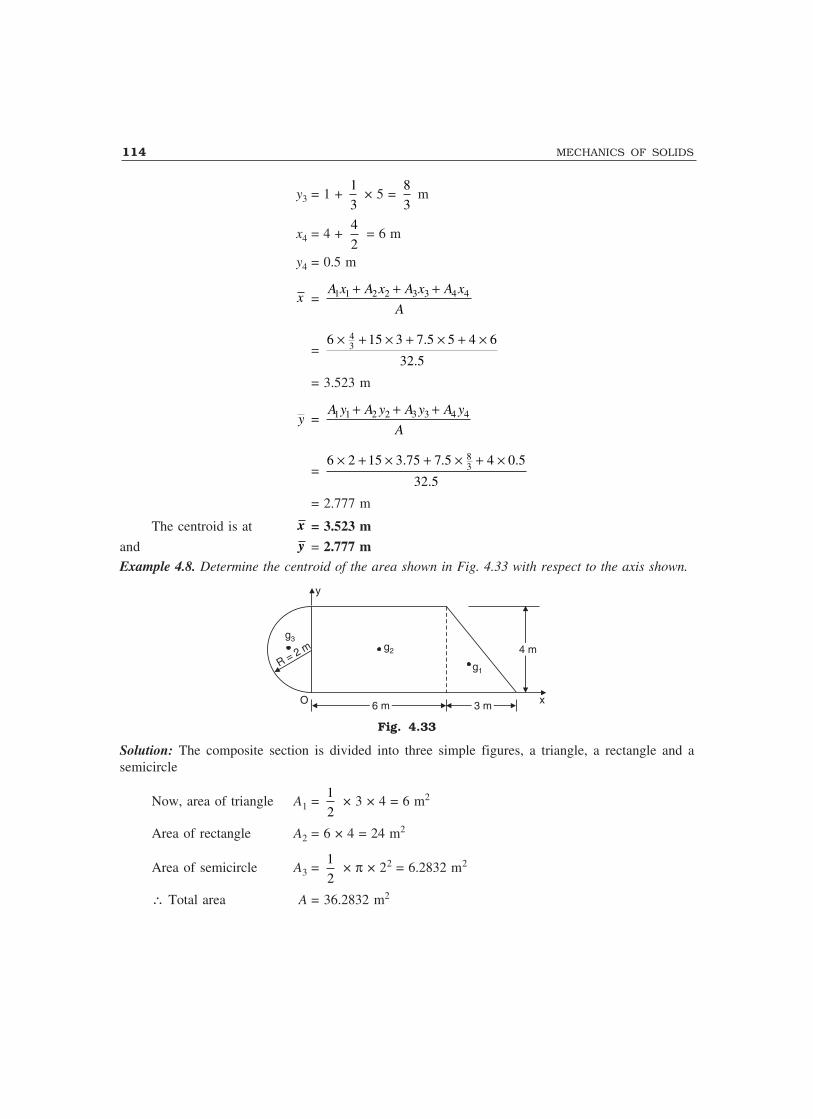
114 MECHANICS OF SOLIDS
y3 = 1 + 1
3 × 5 =
8
3 m
x4 = 4 + 4
2 = 6 m
y4 = 0.5 m
x = 1 1 2 2 3 3 4 4A x A x A x A x
A
� � �
= 436 15 3 7.5 5 4 6
32.5
� � � � � � �
= 3.523 m
y = 1 1 2 2 3 3 4 4A y A y A y A y
A
� � �
= 836 2 15 3.75 7.5 4 0.5
32.5
� � � � � � �
= 2.777 m
The centroid is at x = 3.523 m
and y = 2.777 mExample 4.8. Determine the centroid of the area shown in Fig. 4.33 with respect to the axis shown.
y
R = 2 mg3
g2
g1
O 6 m6 m 3 m3 m
4 m4 m
xx
Fig. 4.33
Solution: The composite section is divided into three simple figures, a triangle, a rectangle and asemicircle
Now, area of triangle A1 = 1
2 × 3 × 4 = 6 m2
Area of rectangle A2 = 6 × 4 = 24 m2
Area of semicircle A3 = 1
2 × π × 22 = 6.2832 m2
∴ Total area A = 36.2832 m2
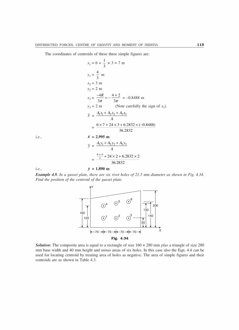
DISTRIBUTED FORCES, CENTRE OF GRAVITY AND MOMENT OF INERTIA 115
The coordinates of centroids of these three simple figures are:
x1 = 6 + 1
3 × 3 = 7 m
y1 = 4
3 m
x2 = 3 my2 = 2 m
x3 = 4 4 2
3 3
R
� �
� �� � = –0.8488 m
y3 = 2 m (Note carefully the sign of x3).
x = 1 1 2 2 3 3A x A x A x
A
� �
= 6 7 24 3 6.2832 ( 0.8488)
36.2832
� � � � � �
i.e., x = 2.995 m
y = 1 1 2 2 3 3A y A y A y
A
� �
= 6 4
3 24 2 6.2832 2
36.2832
� � � � �
i.e., y = 1.890 mExample 4.9. In a gusset plate, there are six rivet holes of 21.5 mm diameter as shown in Fig. 4.34.Find the position of the centroid of the gusset plate.
Y
160160
120120
45
6
1 2 3
5050
130130
140140
200200
X7070 7070 7070 7070
Fig. 4.34
Solution: The composite area is equal to a rectangle of size 160 × 280 mm plus a triangle of size 280mm base width and 40 mm height and minus areas of six holes. In this case also the Eqn. 4.4 can beused for locating centroid by treating area of holes as negative. The area of simple figures and theircentroids are as shown in Table 4.3.
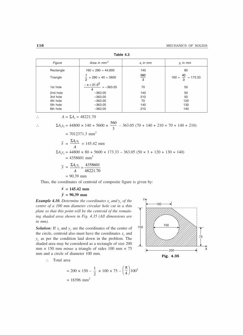
116 MECHANICS OF SOLIDS
Table 4.3
Figure Area in mm 2 xi in mm yi in mm
Rectangle 160 × 280 = 44,800 140 80
Triangle12
× 280 × 40 = 56005603
160 + 403
= 173.33
1st hole− ×π 21.52
4 = –363.05 70 50
2nd hole –363.05 140 503rd hole –363.05 210 504th hole –363.05 70 1205th hole –363.05 140 1306th hole –363.05 210 140
∴ A = ΣAi = 48221.70
∴ ΣAixi = 44800 × 140 + 5600 × 560
3 – 363.05 (70 + 140 + 210 + 70 + 140 + 210)
= 7012371.3 mm3
x = i iA x
A
� = 145.42 mm
ΣAiyi = 44800 × 80 + 5600 × 173.33 – 363.05 (50 × 3 + 120 + 130 + 140)= 4358601 mm3
y = 4358601
48221.70i iA y
A
��
= 90.39 mmThus, the coordinates of centroid of composite figure is given by:
x = 145.42 mmy = 90.39 mm
Example 4.10. Determine the coordinates xc and yc of thecentre of a 100 mm diameter circular hole cut in a thinplate so that this point will be the centroid of the remain-ing shaded area shown in Fig. 4.35 (All dimensions arein mm).
Solution: If xc and yc are the coordinates of the centre ofthe circle, centroid also must have the coordinates xc andyc as per the condition laid down in the problem. Theshaded area may be considered as a rectangle of size 200mm × 150 mm minus a triangle of sides 100 mm × 75mm and a circle of diameter 100 mm.
∴ Total area
= 200 × 150 – 1
2 × 100 × 75 –
π4���� 1002
= 18396 mm2
100100Y
150150100
7575
200200 X
Fig. 4.35

DISTRIBUTED FORCES, CENTRE OF GRAVITY AND MOMENT OF INERTIA 117
xc = x =
21 100200 150 100 100 75 200 100
2 3 4
18396
cx�� �� � � � � � � � � � � �� � �� �
∴ xc(18396) = 200 × 150 × 100 – 1
2 × 100 × 75 × 166.67 –
4
�
× 1002 xc
xc =2375000
26250 = 90.48 mm
Similarly,
18396 yc = 200 × 150 × 75 – 1
2 × 100 × 75 × (150 – 25) –
4
�× 1002 yc
∴ yc =1781250.0
26250 = 67.86 mm
Centre of the circle should be located at (90.48, 67.86) so that this point will be the centroid of theremaining shaded area as shown in Fig. 4.35.
Note: The centroid of the given figure will coincide with the centroid of the figure without circular hole.Hence, the centroid of the given figure may be obtained by determining the centroid of the figure without thecircular hole also.
Example 4.11. Determine the coordinates of the centroid of the plane area shown in Fig. 4.36 withreference to the axis shown. Take x = 40 mm.
4x4x 4x4x6x6x
Y4x4x
8x8x
2xO
R=
4x
8x8x 4x4x 6x6x
R= 4x
4x4x
4x4x
4x4x
X
Fig. 4.36
Solution: The composite figure is divided into the following simple figures:(1) A rectangle A1 = (14x) × (12x) = 168x2
x1 = 7x; y1 = 6x
118 MECHANICS OF SOLIDS
(2) A triangle A2 = 1
2 (6x) × (4x) = 12x2
x2 = 14x + 2x = 16x
y2 = 4
3
x
(3) A rectangle to be subtractedA3 = (–4x) × (4x) = –16x2
x3 = 2x; y3 = 8x + 2x = 10x(4) A semicircle to be subtracted
A4 = –1
2π (4x)2 = –8πx2
x4 = 6x
y4 = 4
3
R
π = 4 ×
4
3
16
3
( )x x
π π=
(5) A quarter of a circle to be subtracted
A5 = 1
4� × π (4x)2 = –4πx2
x5 = 14x – 4
3
R
π = 14x – (4)
4
3
x
�� = 12.3023x
y5 = 12x – 4 × 4
3
x
�� = 10.3023x
Total area A = 168x2 + 12x2 – 16x2 – 8πx2 – 4πx2
= 126.3009x2
x = i iA x
A
�
ΣAixi = 168x2 × 7x + 12x2 × 16x – 16x2 × 2x – 8πx2 × 6x – 4πx2 × 12.3023x= 1030.6083x3
∴ x = 3
2
1030.6083
126.3009
x
x
= 8.1599x = 8.1599 × 40 (since x = 40 mm)= 326.40 mm
y = i iA y
A
�
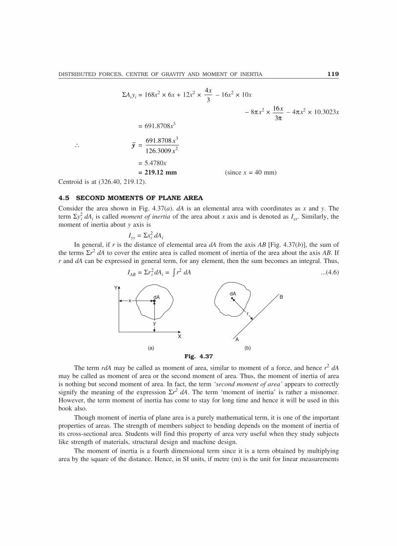
DISTRIBUTED FORCES, CENTRE OF GRAVITY AND MOMENT OF INERTIA 119
ΣAiyi = 168x2 × 6x + 12x2 × 4
3
x – 16x2 × 10x
– 8πx2 × 16
3
x
π – 4πx2 × 10.3023x
= 691.8708x3
∴ y = 3
2
691.8708
126.3009
x
x
= 5.4780x= 219.12 mm (since x = 40 mm)
Centroid is at (326.40, 219.12).
4.5 SECOND MOMENTS OF PLANE AREA
Consider the area shown in Fig. 4.37(a). dA is an elemental area with coordinates as x and y. Theterm Σy2
i dAi is called moment of inertia of the area about x axis and is denoted as Ixx. Similarly, themoment of inertia about y axis is
Iyy = Σx2i dAi
In general, if r is the distance of elemental area dA from the axis AB [Fig. 4.37(b)], the sum ofthe terms Σr2 dA to cover the entire area is called moment of inertia of the area about the axis AB. Ifr and dA can be expressed in general term, for any element, then the sum becomes an integral. Thus,
IAB = Σr2i dAi = � r2 dA ...(4.6)
Y
X
xx
yy
dAdA
rr
B
A
(a) (b)
Fig. 4.37
The term rdA may be called as moment of area, similar to moment of a force, and hence r2 dAmay be called as moment of area or the second moment of area. Thus, the moment of inertia of areais nothing but second moment of area. In fact, the term ‘second moment of area’ appears to correctlysignify the meaning of the expression Σr2 dA. The term ‘moment of inertia’ is rather a misnomer.However, the term moment of inertia has come to stay for long time and hence it will be used in thisbook also.
Though moment of inertia of plane area is a purely mathematical term, it is one of the importantproperties of areas. The strength of members subject to bending depends on the moment of inertia ofits cross-sectional area. Students will find this property of area very useful when they study subjectslike strength of materials, structural design and machine design.
The moment of inertia is a fourth dimensional term since it is a term obtained by multiplyingarea by the square of the distance. Hence, in SI units, if metre (m) is the unit for linear measurements
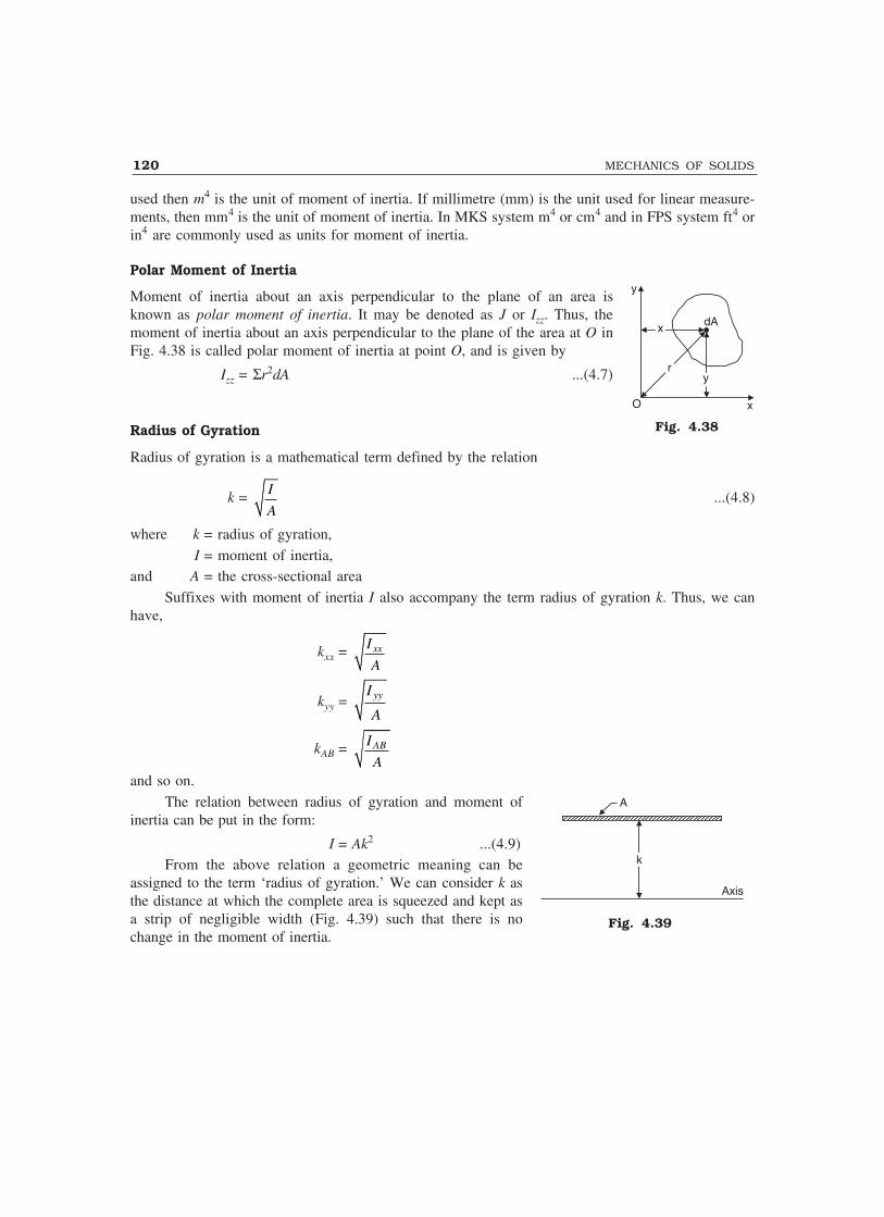
120 MECHANICS OF SOLIDS
used then m4 is the unit of moment of inertia. If millimetre (mm) is the unit used for linear measure-ments, then mm4 is the unit of moment of inertia. In MKS system m4 or cm4 and in FPS system ft4 orin4 are commonly used as units for moment of inertia.
Polar Moment of Inertia
Moment of inertia about an axis perpendicular to the plane of an area isknown as polar moment of inertia. It may be denoted as J or Izz. Thus, themoment of inertia about an axis perpendicular to the plane of the area at O inFig. 4.38 is called polar moment of inertia at point O, and is given by
Izz = Σr2dA ...(4.7)
Radius of Gyration
Radius of gyration is a mathematical term defined by the relation
k = I
A...(4.8)
where k = radius of gyration,I = moment of inertia,
and A = the cross-sectional areaSuffixes with moment of inertia I also accompany the term radius of gyration k. Thus, we can
have,
kxx = xxI
A
kyy = yyI
A
kAB = ABI
Aand so on.
The relation between radius of gyration and moment ofinertia can be put in the form:
I = Ak2 ...(4.9)From the above relation a geometric meaning can be
assigned to the term ‘radius of gyration.’ We can consider k asthe distance at which the complete area is squeezed and kept asa strip of negligible width (Fig. 4.39) such that there is nochange in the moment of inertia.
y
x
xx
rr
dA
yy
O
Fig. 4.38
Fig. 4.39
A
kk
Axis

DISTRIBUTED FORCES, CENTRE OF GRAVITY AND MOMENT OF INERTIA 121
Theorems of Moments of Inertia
There are two theorems of moment of inertia:(1) Perpendicular axis theorem, and(2) Parallel axis theorem.These are explained and proved below.
Perpendicular Axis Theorem
The moment of inertia of an area about an axis pependicular to its plane (polar moment of inertia) atany point O is equal to the sum of moments of inertia about any two mutually perpendicular axisthrough the same point O and lying in the plane of the area.
Referring to Fig. 4.40, if z-z is the axis normal to the plane ofpaper passing through point O, as per this theorem,
Izz = Ixx + Iyy ... (4.10)The above theorem can be easily proved. Let us consider an elemental
area dA at a distance r from O. Let the coordinates of dA be x and y.Then from definition:
Izz =�Σr2dA
= Σ(x2 + y2)dA
= Σx2dA + Σy2dA
Izz = Ixx + Iyy
Parallel Axis Theorem
Moment of inertia about any axis in the plane of an areais equal to the sum of moment of inertia about a parallelcentroidal axis and the product of area and square of thedistance between the two parallel axis. Referring toFig. 4.41 the above theorem means:
IAB = IGG + A yc2 ...(4.11)
whereIAB = moment of inertia about axis AB
IGG = moment of inertia about centroidal axis GGparallel to AB.
A = the area of the plane figure given andyc = the distance between the axis AB and the parallel centroidal
axis GG.Proof: Consider an elemental parallel strip dA at a distance y from the centroidal axis (Fig. 4.41).
Then, IAB = Σ(y + yc)2dA
= Σ(y2 + 2y yc + yc2)dA
= Σy2dA + Σ2y yc dA + Σ yc2dA
Now, Σy2dA = Moment of inertia about the axis GG
= IGG
y
x
xx
rr
dA
yy
O
Fig. 4.40
G G
A B
ycyc
Centroid
A
dA
y
Fig. 4.41

122 MECHANICS OF SOLIDS
Σ2yyc dA = 2yc Σy dA
= 2yc A ydA
A
�
In the above term 2yc A is constant and ydA
A
� is the distance of centroid from the reference axis
GG. Since GG is passing through the centroid itself ydA
A is zero and hence the term Σ2yycdA is zero.
Now, the third term,
Σyc2dA = yc
2ΣdA
= Ayc2
∴ IAB = IGG + Ayc2
Note: The above equation cannot be applied to any two parallel axis. One of the axis (GG) must be centroidalaxis only.
4.6 MOMENT OF INERTIA FROM FIRST PRINCIPLES
For simple figures, moment of inertia can be obtained by writing the general expression for anelement and then carrying out integration so as to cover the entire area. This procedure is illustratedwith the following three cases:
(1) Moment of inertia of a rectangle about the centroidal axis(2) Moment of inertia of a triangle about the base(3) Moment of inertia of a circle about a diametral axis
(1) Moment of Inertia of a Rectangle about the Centroidal Axis: Consider a rectangle of width band depth d (Fig. 4.42). Moment of inertia about the centroidal axis x-x parallel to the short side isrequired.
Consider an elemental strip of width dy at a distance y from the axis. Moment of inertia of theelemental strip about the centroidal axis xx is:
= y2dA
= y2b dy
∴ Ixx = / 2
/ 2
d
d�� y2b dy
= b
/ 23
/ 23
d
d
y
�
� �� � �
= b 3 3
24 24
d d� ���
� �
Ixx = 3
12
bd
x x
dy
yy
d/2d/2
d/2d/2
bb
Fig. 4.42

DISTRIBUTED FORCES, CENTRE OF GRAVITY AND MOMENT OF INERTIA 123
(2) Moment of Inertia of a Triangle about its Base:Moment of inertia of a triangle with base width b andheight h is to be determined about the base AB(Fig. 4.43).
Consider an elemental strip at a distance y fromthe base AB. Let dy be the thickness of the strip anddA its area. Width of this strip is given by:
b1 = ( )h y
h
� × b
Moment of inertia of this strip about AB
= y2dA
= y2 b1 dy
= y2 ( )h y
h
� × b × dy
∴ Moment of inertia of the triangle about AB,
IAB = 2
0
( )h y h y bdy
h
��
= 3
2
0
h yy
h
� � �� �
� bdy
= b3 4
03 4
hy y
h
� ���
� �
= b3 4
3 4
h h
h
� ���
� �
IAB = 3
12
bh
(3) Moment of Inertia of a Circle about its DiametralAxis: Moment of inertia of a circle of radius R is requiredabout it’s diametral axis as shown in Fig. 4.44
Consider an element of sides rdθ and dr as shown in thefigure. It’s moment of inertia about the diametral axis x-x:
= y2dA= (r sin θ)2 r dθ dr
= r3 sin2 θ dθ dr∴ Moment of inertia of the circle about x-x is given by
Ixx = 0 0
2R
� �π
r3 sin2 θ dθ dr
A
dy
yy
bb
b1b1
B
hh
Fig. 4.43
dd
X X
RR
�d�rr
rd�
dr
Fig. 4.44
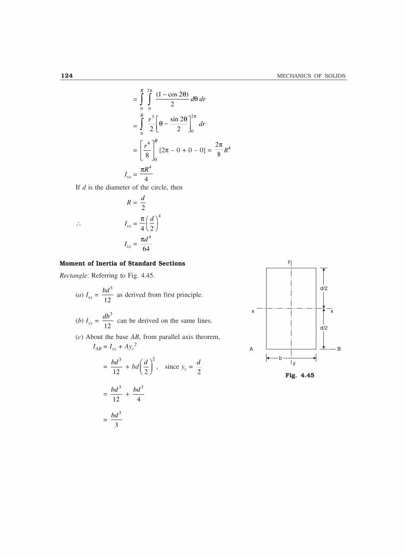
124 MECHANICS OF SOLIDS
= 0 0
21 2
2
R
d dr� �−
πθ θ( cos )
= 0
3
0
2
2
2
2
Rr
dr� −���
�
θ θ πsin
= 4
08
Rr� �
� � �
[2π – 0 + 0 – 0] = 2
8
πR4
Ixx = πR4
4If d is the diameter of the circle, then
R = 2
d
∴ Ixx = π4 2
4d����
Ixx = πd 4
64
Moment of Inertia of Standard Sections
Rectangle: Referring to Fig. 4.45.
(a) Ixx = 3
12
bd as derived from first principle.
(b) Iyy = 3
12
db can be derived on the same lines.
(c) About the base AB, from parallel axis theorem,IAB = Ixx + Ayc
2
= 3
12
bd + bd
2
2
d� �� �
, since yc = 2
d
= 3
12
bd +
3
4
bd
= 3
3
bd
Fig. 4.45
y
B
ybb
A
x x
d/2d/2
d/2d/2

DISTRIBUTED FORCES, CENTRE OF GRAVITY AND MOMENT OF INERTIA 125
Hollow Rectangular Section: Referring to Fig. 4.46, Moment of inertiaIxx = Moment of inertia of larger rectangle–Moment of inertia ofhollow portion. That is,
= 3 3
12 12
BD bd�
= 1
12(BD3 – bd3)
Triangle—Referring to Fig. 4.47.(a) About the base:As found from first principle
IAB = 3
12
bh
(b) About centroidal axis, x-x parallel to base:From parallel axis theorem,
IAB = Ixx + Ayc2
Now, yc, the distance between the non-centroidal axis AB and centroidal axis x-x, is equal to 3
h.
∴3
12
bh= Ixx +
1
2bh
2
3
h� �� �
= Ixx + 3
18
bh
∴ Ixx = 3
12
bh –
3
18
bh
= 3
36
bh
Moment of Inertia of a Circle about any diametral axis
= πd 4
64(as found from first principle)
Fig. 4.46
A
G hh
h/3h/3
bb BB
Fig. 4.47
bbD/2D/2
D/2D/2
x x
dd
BB

126 MECHANICS OF SOLIDS
Moment of Inertia of a Hollow Circle: Referring to Fig. 4.48.IAB = Moment of inertia of solid circle of diameter D about AB– Moment of inertia of circle of diameter d about AB. That is,
= 4
64
D�
– 4
64
d�
= 64
�
(D4 – d4)
Moment of Inertia of a Semicircle: (a) About Diametral Axis:If the limit of integration is put as 0 to π instead of 0 to 2π inthe derivation for the moment of inertia of a circle aboutdiametral axis the moment of inertia of a semicircle isobtained. It can be observed that the moment of inertia of asemicircle (Fig. 4.49) about the diametral axis AB:
= 12 64 128
4 4
× =π πd d
(b) About Centroidal Axis x-x:Now, the distance of centroidal axis yc from the diametralaxis is given by:
yc = 4
3
2
3
R d
π π=
and, Area A = 12 4 8
2 2
× =π πd d
From parallel axis theorem,IAB = Ixx + Ayc
2
πd 4
128= Ixx +
ππ
d d2 2
8
2
3× ����
Ixx = π
πd d4 4
128 18−
= 0.0068598 d 4
Moment of Inertia of a Quarter of a Circle: (a) About the Base: If the limit of integration is put as 0
to π2
instead of 0 to 2π in the derivation for moment of inertia of a circle the moment of inertia of a
quarter of a circle is obtained. It can be observed that moment of inertia of the quarter of a circleabout the base AB.
A B
dd
DD
Fig. 4.48
x xG
ycyc
dd
A B
Fig. 4.49

DISTRIBUTED FORCES, CENTRE OF GRAVITY AND MOMENT OF INERTIA 127
= 14 64 256
4 4
× =ππ
πd d
(b) About Centroidal Axis x-x:Now, the distance of centroidal axis yc from the base is given by:
yc = 4 2
3 3
R d�
� �
and the area A = 2 21
4 4 16
d d� �� �
From parallel axis theorem,IAB = Ixx + Ayc
2
4
256
d�= Ixx +
22 2
16 3
d d� � �� ��
Ixx = 4 4
256 36
d d��
�= 0.00343 d4
The moment of inertia of common standard sections are presented in Table 4.4.
Table 4.4 Moment of Inertia of Standard Sections
Shape Axis Moment of Inertia
Rectangle (a) Centroidal axis x-x Ixx = 3
12bd
(b) Centroidal axis y-y Iyy = 3
12db
(c) A – B IAB = 3
3bd
Hollow Rectangle Centroidal axis x-x Ixx = �3 3
12BD bd
X X
G
A B
RR
4R3�
Fig. 4.50
d/2d/2
d/2d/2
X X
Y
Ab/2b/2 b/2b/2
B
Y
X Xbb
dd
BB
DD
(Contd.)
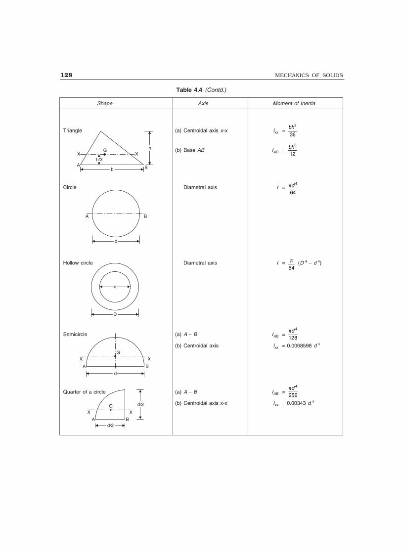
128 MECHANICS OF SOLIDS
Triangle (a) Centroidal axis x-x Ixx = 3
36bh
(b) Base AB IAB = 3
12bh
Circle Diametral axis I = � 4
64d
Hollow circle Diametral axis I = �64
(D 4 – d 4)
Semicircle (a) A – B IAB = � 4
128d
(b) Centroidal axis Ixx = 0.0068598 d 4
Quarter of a circle (a) A – B IAB = � 4
256d
(b) Centroidal axis x-x Ixx = 0.00343 d 4
Table 4.4 (Contd.)
Shape Axis Moment of Inertia
X Xh/3h/3
G
bbA B
hh
A B
dd
DD
dd
X XG
A Bd/2d/2
d/2d/2
X XG
A B
dd
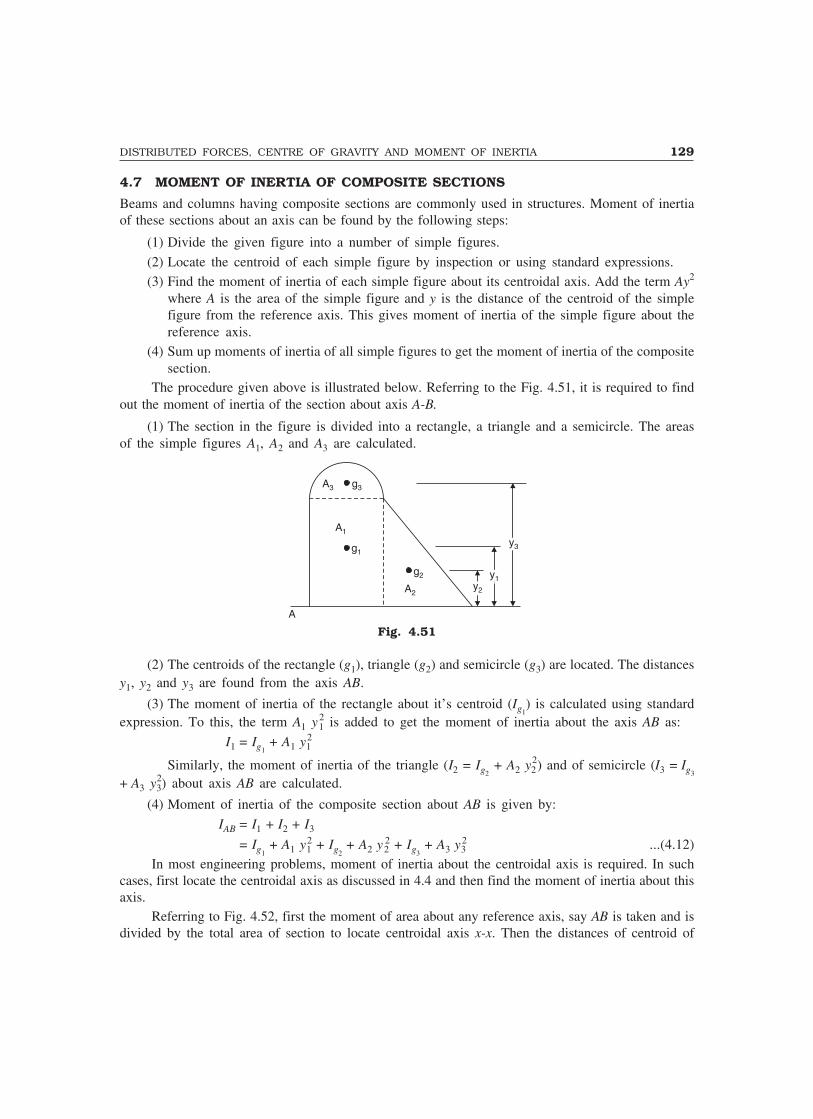
DISTRIBUTED FORCES, CENTRE OF GRAVITY AND MOMENT OF INERTIA 129
4.7 MOMENT OF INERTIA OF COMPOSITE SECTIONS
Beams and columns having composite sections are commonly used in structures. Moment of inertiaof these sections about an axis can be found by the following steps:
(1) Divide the given figure into a number of simple figures.
(2) Locate the centroid of each simple figure by inspection or using standard expressions.(3) Find the moment of inertia of each simple figure about its centroidal axis. Add the term Ay2
where A is the area of the simple figure and y is the distance of the centroid of the simplefigure from the reference axis. This gives moment of inertia of the simple figure about thereference axis.
(4) Sum up moments of inertia of all simple figures to get the moment of inertia of the compositesection.
The procedure given above is illustrated below. Referring to the Fig. 4.51, it is required to findout the moment of inertia of the section about axis A-B.
(1) The section in the figure is divided into a rectangle, a triangle and a semicircle. The areasof the simple figures A1, A2 and A3 are calculated.
A3
A1
g3
g1
g2
A2y2y2
y1y1
y3y3
A
Fig. 4.51
(2) The centroids of the rectangle (g1), triangle (g2) and semicircle (g3) are located. The distancesy1, y2 and y3 are found from the axis AB.
(3) The moment of inertia of the rectangle about it’s centroid (Ig1) is calculated using standard
expression. To this, the term A1 y12 is added to get the moment of inertia about the axis AB as:
I1 = Ig1 + A1 y1
2
Similarly, the moment of inertia of the triangle (I2 = Ig2 + A2 y2
2) and of semicircle (I3 = Ig3
+ A3 y32) about axis AB are calculated.
(4) Moment of inertia of the composite section about AB is given by:
IAB = I1 + I2 + I3
= Ig1 + A1 y1
2 + Ig2 + A2 y2
2 + Ig3 + A3 y3
2 ...(4.12)In most engineering problems, moment of inertia about the centroidal axis is required. In such
cases, first locate the centroidal axis as discussed in 4.4 and then find the moment of inertia about thisaxis.
Referring to Fig. 4.52, first the moment of area about any reference axis, say AB is taken and isdivided by the total area of section to locate centroidal axis x-x. Then the distances of centroid of

130 MECHANICS OF SOLIDS
individual figures yc1, yc2 and yc3 from the axis x-x are determined. The moment of inertia of thecomposite section about the centroidal axis x-x is calculated using the expression:
Ixx = Ig1 + A1
2 yc1 + Ig2 + A2
2 yc2 + Ig3 + A3
2 yc3 ...(4.13)
g1
g2
g3
A
–y–y
y 1cy 2y 2c
y 3y 3c
B
g
Fig. 4.52
Sometimes the moment of inertia is found about a conveninet axis and then using parallel axistheorem, the moment of inertia about centroidal axis is found.
In the above example, the moment of inertia IAB is found and yc, the distance of CG from axisAB is calculated. Then from parallel axis theorem,
IAB = Ixx + Ay2c
Ixx = IAB – Ay2c
where A is the area of composite section.Example 4.12. Determine the moment of inertia of the sectionshown in Fig. 4.53 about an axis passing through the centroidand parallel to the top most fibre of the section. Also determinemoment of inertia about the axis of symmetry. Hence find radiiof gyration.
Solution: The given composite section can be divided into tworectangles as follows:
Area A1 = 150 × 10 = 1500 mm2
Area A2 = 140 × 10 = 1400 mm2
Total Area A = A1 + A2 = 2900 mm2
Due to symmetry, centroid lies on the symmetric axis y-y.The distance of the centroid from the top most fibre is
given by:
yc = Sum of moment of the areas about the top most fibre
Total area
= 1500 5 + 1400(10 + 70)
2900
�
= 41.21 mmReferring to the centroidal axis x-x and y-y, the centroid of A1 is g1 (0.0, 36.21) and that of A2 is
g2 (0.0, 38.79).
Fig. 4.53
150150y
g2A1
X XG
g1
A2
10y
–y–y
10
140140
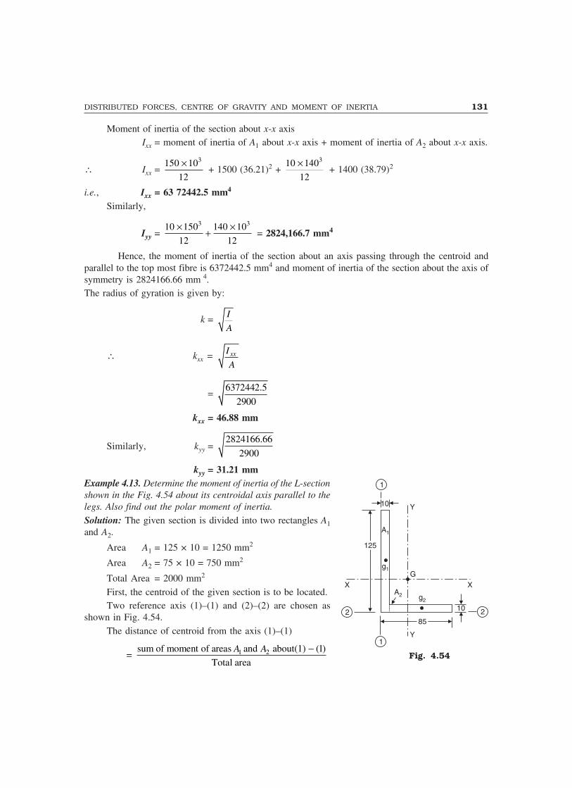
DISTRIBUTED FORCES, CENTRE OF GRAVITY AND MOMENT OF INERTIA 131
Moment of inertia of the section about x-x axisIxx = moment of inertia of A1 about x-x axis + moment of inertia of A2 about x-x axis.
∴ Ixx = 3150 10
12
� + 1500 (36.21)2 +
310 140
12
� + 1400 (38.79)2
i.e., Ixx = 63 72442.5 mm4
Similarly,
Iyy = 3 310 150 140 10
12 12
� �� = 2824,166.7 mm4
Hence, the moment of inertia of the section about an axis passing through the centroid andparallel to the top most fibre is 6372442.5 mm4 and moment of inertia of the section about the axis ofsymmetry is 2824166.66 mm
4.The radius of gyration is given by:
k = I
A
∴ kxx = xxI
A
= 6372442.5
2900
kxx = 46.88 mm
Similarly, kyy = 2824166.66
2900
kyy = 31.21 mmExample 4.13. Determine the moment of inertia of the L-sectionshown in the Fig. 4.54 about its centroidal axis parallel to thelegs. Also find out the polar moment of inertia.
Solution: The given section is divided into two rectangles A1and A2.
Area A1 = 125 × 10 = 1250 mm2
Area A2 = 75 × 10 = 750 mm2
Total Area = 2000 mm2
First, the centroid of the given section is to be located.Two reference axis (1)–(1) and (2)–(2) are chosen as
shown in Fig. 4.54.The distance of centroid from the axis (1)–(1)
= 1 2sum of moment of areas and about(1) (1)
Total area
A A �
1
10 Y
A1
125125
g1G
X X
2 2
1
A2 g2
8585
10
Y
Fig. 4.54

132 MECHANICS OF SOLIDS
i.e., x =
75120 5 750 10
22000
� � � � �� �
= 20.94 mmSimilarly,the distance of the centroid from the axis (2)–(2)
= y =
1251250 750 5
22000
� � � = 40.94 mm
With respect to the centroidal axis x-x and y-y, the centroid of A1 is g1 (15.94, 21.56) and that ofA2 is g2 (26.56, 35.94).
∴ Ixx = Moment of inertia of A1 about x-x axis + Moment of inertia of A2 about x-x axis
∴ Ixx = 310 125
12
� + 1250 × 21.562 +
375 10
12
� + 750 × 39.942
i.e., Ixx = 3411298.9 mm4
Similarly,
Iyy = 3125 10
12
� + 1250 × 15.942 +
310 75
12
� + 750 × 26.562
i.e., Iyy = 1208658.9 mm4
Polar moment of inertia = Ixx + Iyy
= 3411298.9 + 12,08658.9
Izz = 4619957.8 mm4
Example 14. Determine the moment of inertia of the symmertic I-section shown in Fig. 4.55 about itscentroidal axis x-x and y-y.
Also, determine moment of inertia of the section abouta centroidal axis perpendicular to x-x axis and y-y axis.
Solution: The section is divided into three rectangles A1, A2and A3.
Area A1 = 200 × 9 = 1800 mm2
Area A2 = (250 – 9 × 2) × 6.7 = 1554.4 mm2
Area A3 = 200 × 9 = 1800 mm2
Total Area A = 5154.4 mm2
The section is symmetrical about both x-x and y-y axis.Therefore, its centroid will coincide with the centroid ofrectangle A2.
With respect to the centroidal axis x-x and y-y, thecentroid of rectangle A1 is g1 (0.0, 120.5), that of A2 is g2(0.0, 0.0) and that of A3 is g3 (0.0, 120.5).
Y200200
g1A1
9
6.7
250250
g2X X
A2
g3 A3
Fig. 4.55
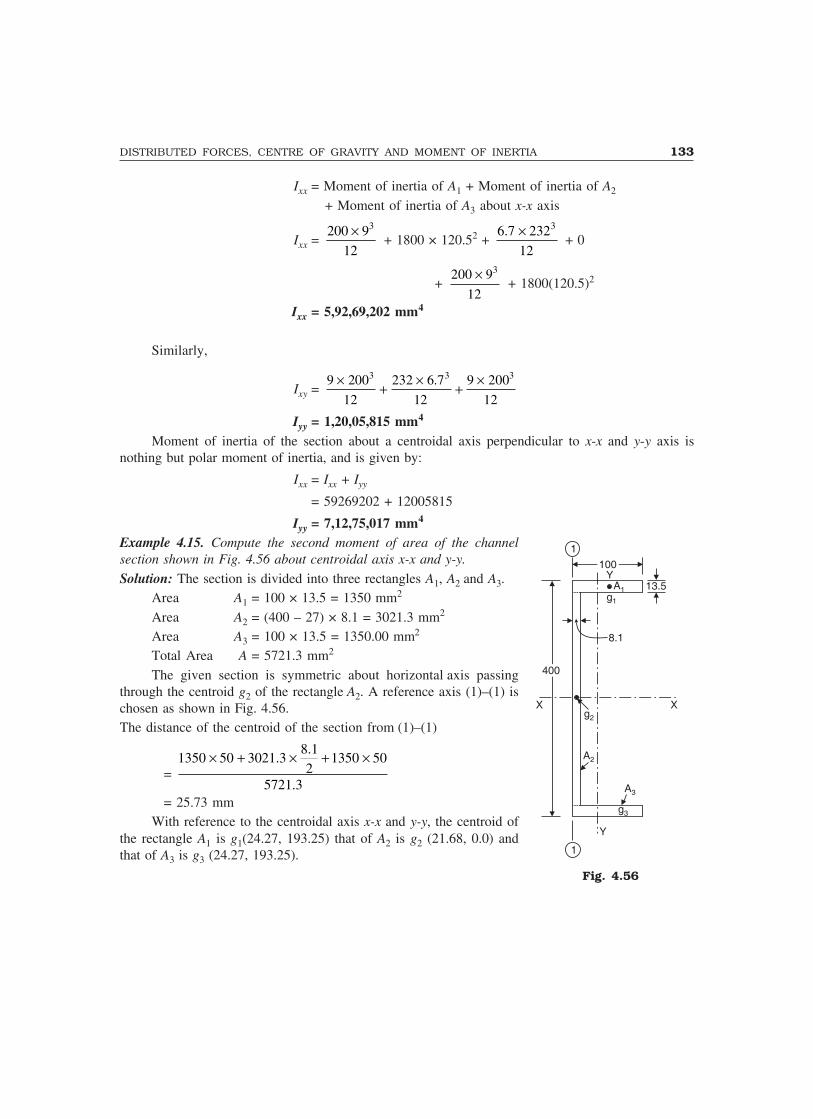
DISTRIBUTED FORCES, CENTRE OF GRAVITY AND MOMENT OF INERTIA 133
Ixx = Moment of inertia of A1 + Moment of inertia of A2
+ Moment of inertia of A3 about x-x axis
Ixx = 3200 9
12
� + 1800 × 120.52 +
36.7 232
12
� + 0
+ 3200 9
12
� + 1800(120.5)2
Ixx = 5,92,69,202 mm4
Similarly,
Ixy = 3 3 39 200 232 6.7 9 200
12 12 12
� � �� �
Iyy = 1,20,05,815 mm4
Moment of inertia of the section about a centroidal axis perpendicular to x-x and y-y axis isnothing but polar moment of inertia, and is given by:
Ixx = Ixx + Iyy
= 59269202 + 12005815
Iyy = 7,12,75,017 mm4
Example 4.15. Compute the second moment of area of the channelsection shown in Fig. 4.56 about centroidal axis x-x and y-y.
Solution: The section is divided into three rectangles A1, A2 and A3.Area A1 = 100 × 13.5 = 1350 mm2
Area A2 = (400 – 27) × 8.1 = 3021.3 mm2
Area A3 = 100 × 13.5 = 1350.00 mm2
Total Area A = 5721.3 mm2
The given section is symmetric about horizontal axis passingthrough the centroid g2 of the rectangle A2. A reference axis (1)–(1) ischosen as shown in Fig. 4.56.The distance of the centroid of the section from (1)–(1)
=
8.11350 50 3021.3 1350 50
25721.3
� � � � �
= 25.73 mmWith reference to the centroidal axis x-x and y-y, the centroid of
the rectangle A1 is g1(24.27, 193.25) that of A2 is g2 (21.68, 0.0) andthat of A3 is g3 (24.27, 193.25).
Fig. 4.56
1
100100
13.5A1g1
8.1
400400
g2
X X
A2
A3
g3
Y
1
Y

134 MECHANICS OF SOLIDS
∴ Ixx = Moment of inertia of A1, A2 and A3 about x-x
= 3100 13.5
12
� + 1350 × 193.252
+ 3 38.1 373 100 13.5
12 12
� �� + 1350 ×193.252
Ixx = 1.359 ×108 mm4
Similarly, Iyy = 313.5 100
12
� + 1350 × 24.272 +
3273 8.1
12
� + 3021.3
× 21.682 + 313.5 100
12
� + 1350 × 24.272
Iyy = 52,72557.6 mm4
Example 4.16. Determine the polar moment of inertia of the I-section shown in the Fig. 4.57. Alsodetermine the radii of gyration with respect to x-x axis and y-y axis.
y8080
12A1 g1
12
A2
g2
150150
x x
1 110
g3A3
120120y
Fig. 4.57
Solution: The section is divided into three rectangles as shown in Fig. 4.57Area A1 = 80 × 12 = 960 mm2
Area A2 = (150 – 22) × 12 = 1536 mm2
Area A3 = 120 × 10 = 1200 mm2
Total area A = 3696 mm2
Due to symmetry, centroid lies on axis y-y. The bottom fibre (1)–(1) is chosen as reference axisto locate the centroid.
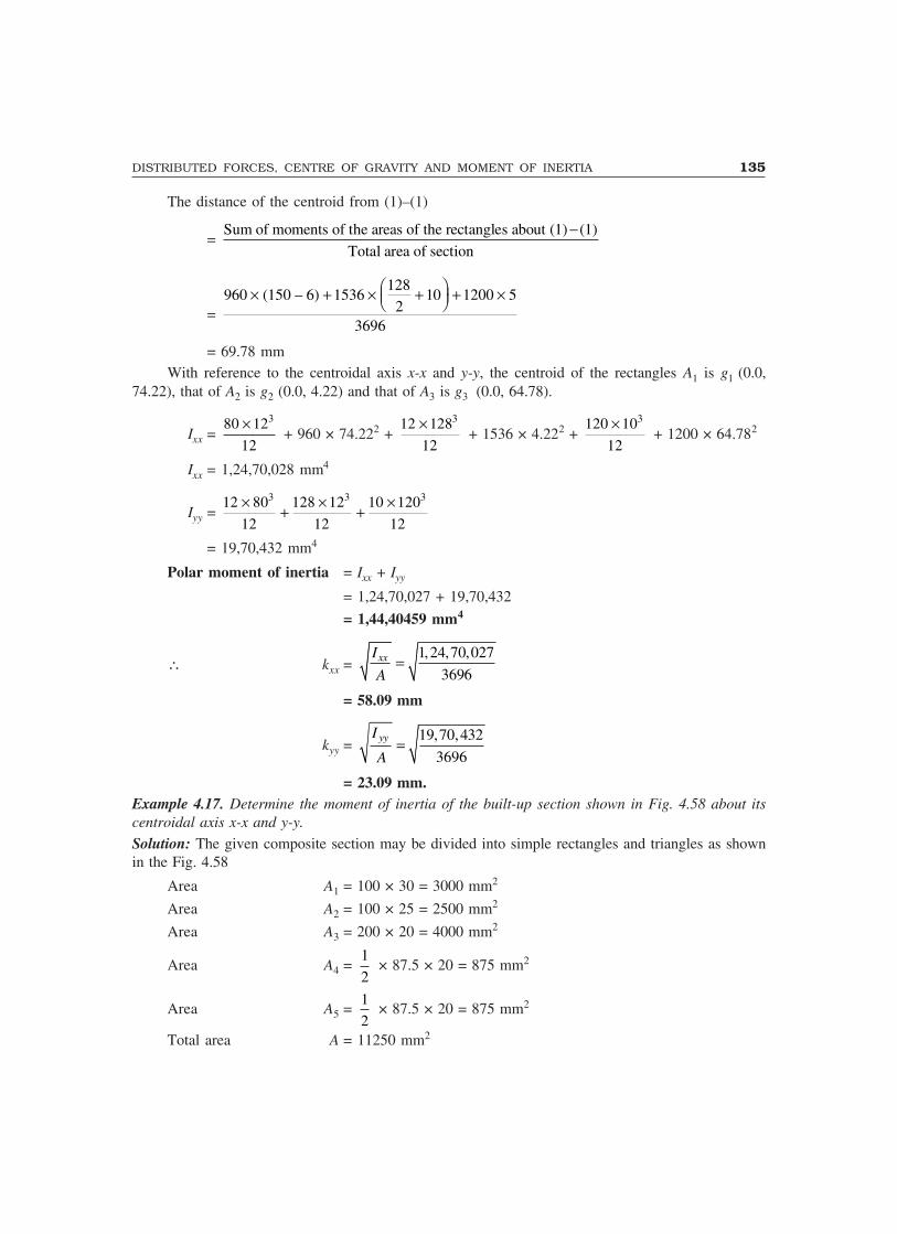
DISTRIBUTED FORCES, CENTRE OF GRAVITY AND MOMENT OF INERTIA 135
The distance of the centroid from (1)–(1)
= Sum of moments of the areas of the rectangles about (1) (1)
Total area of section
�
=
128960 (150 – 6) 1536 10 1200 5
23696
� �� � � � � �� ��
= 69.78 mmWith reference to the centroidal axis x-x and y-y, the centroid of the rectangles A1 is g1 (0.0,
74.22), that of A2 is g2 (0.0, 4.22) and that of A3 is g3 (0.0, 64.78).
Ixx = 380 12
12
� + 960 × 74.222 +
312 128
12
� + 1536 × 4.222 +
3120 10
12
� + 1200 × 64.782
Ixx = 1,24,70,028 mm4
Iyy = 3 3 312 80 128 12 10 120
12 12 12
� � �� �
= 19,70,432 mm4
Polar moment of inertia = Ixx + Iyy
= 1,24,70,027 + 19,70,432
= 1,44,40459 mm4
∴ kxx = 1,24,70,027
3696xxI
A
= 58.09 mm
kyy = 19,70,432
3696yyI
A
= 23.09 mm.Example 4.17. Determine the moment of inertia of the built-up section shown in Fig. 4.58 about itscentroidal axis x-x and y-y.
Solution: The given composite section may be divided into simple rectangles and triangles as shownin the Fig. 4.58
Area A1 = 100 × 30 = 3000 mm2
Area A2 = 100 × 25 = 2500 mm2
Area A3 = 200 × 20 = 4000 mm2
Area A4 = 1
2 × 87.5 × 20 = 875 mm2
Area A5 = 1
2 × 87.5 × 20 = 875 mm2
Total area A = 11250 mm2

136 MECHANICS OF SOLIDS
y
100100
3030 g1A1
2525
A2
g2
8080
A4g4 g5 A5
x x
g3 A3
2020
20201
200200y
1
Fig. 4.58
Due to symmetry, centroid lies on the axis y-y.A reference axis (1)–(1) is choosen as shown in the figure.The distance of the centroidal axis from (1)–(1)
y = sum of moment of areas about (1)–(1)
Total area
=
13000 135 2500 70 4000 10 875 20 20 2
311250
� �� � � � � � � � �� ��
= 59.26 mmWith reference to the centroidal axis x-x and y-y, the centroid of the rectangle A1 is g1 (0.0, 75.74),
that of A2 is g2(0.0, 10.74), that of A3 is g3 (0.0, 49.26), the centroid of triangle A4 is g4 (41.66, 32.59)and that of A5 is g5 (41.66, 32.59).
Ixx = 3100 30
12
� + 3000 × 75.742 +
325 100
12
� + 2500 × 10.742 +
3200 20
12
� + 4000
× 49.262 + 387.5 20
36
� + 875 × 32.592 +
387.5 20
36
� + 875 × 32.592
Ixx = 3,15,43,447 mm4
Iyy = 3 3 3 330 100 100 25 20 200 20 87.5
12 12 12 36
� � � �� � � + 875 × 41.662
+ 320 87.5
36
� + 875 × 41.662
Iyy = 1,97,45,122 mm4.

DISTRIBUTED FORCES, CENTRE OF GRAVITY AND MOMENT OF INERTIA 137
Example 4.18. Determine the moment of inertia of the built-up section shown in the Fig. 4.59 aboutan axis AB passing through the top most fibre of the section as shown.
A B400400
10
10
20
380380
10
100100 100100150150
Fig. 4.59
Solution: In this problem, it is required to find out the moment of inertia of the section about an axisAB. So there is no need to find out the position of the centroid.
The given section is split up into simple rectangles as shown in Fig. 4.59.Now,Moment of inertia about AB = Sum of moments of inertia of the rectangle about AB
= 3400 20
12
� + 400 × 20 × 102 +
100 10
12100 10 20 5
32× + × × +
�
��
�
��( ) × 2
+ 100 380
1210 380 30 190
32× + × × +
�
��
�
��( ) × 2
+ 100 10
12100 10 20 10 380 5
32× + × × + + +
�
��
�
��( ) × 2
IAB = 8.06093 × 108 mm4.Example 4.19. Calculate the moment of inertia of thebuilt-up section shown in Fig. 4.60 about a centroidal axisparallel to AB. All members are 10 mm thick.
Solution: The built-up section is divided into six simplerectangles as shown in the figure.
The distance of centroidal axis from AB
= Sum of the moment of areas about
Total area
AB
= i iA y
A�
Fig. 4.60
A B250250
X X
5050
10
105050
250250
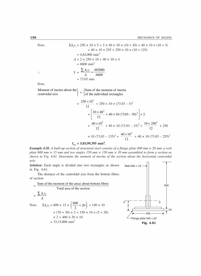
138 MECHANICS OF SOLIDS
Now, ΣAiyi = 250 × 10 × 5 + 2 × 40 × 10 × (10 + 20) + 40 × 10 × (10 + 5)+ 40 × 10 × 255 + 250 × 10 × (10 + 125)
= 4,82,000 mm3
A = 2 × 250 × 10 + 40 × 10 × 4= 6600 mm2
∴ y = 482000
6600i iA y
A�
= 73.03 mmNow,
Moment of inertia about thecentroidal axis
��
= Sum of the moment of inertiaof the individual rectangles��
= 3250 10
12
� + 250 × 10 × (73.03 – 5)2
+ 10 403×
+ × −�
��
�
�� ×
1240 10 73 03 30 22( . )
+ 340 10
12
� + 40 × 10 (73.03 – 15)2 +
310 250
12
� + 250
× 10 (73.03 – 135)2 + 340 10
12
� + 40 × 10 (73.03 – 255)2
Ixx = 5,03,99,395 mm4.Example 4.20. A built-up section of structural steel consists of a flange plate 400 mm × 20 mm, a webplate 600 mm × 15 mm and two angles 150 mm × 150 mm × 10 mm assembled to form a section asshown in Fig. 4.61. Determine the moment of inertia of the section about the horizontal centroidalaxis.Solution: Each angle is divided into two rectangles as shownin Fig. 4.61.
The distance of the centroidal axis from the bottom fibresof section
= Sum of the moment of the areas about bottom fibres
Total area of the section
= i iA y
A�
Now, ΣAiyi = 600 × 15 × 600
202
� ��� �� + 140 × 10
× (70 + 30) × 2 + 150 × 10 × (5 + 20)× 2 + 400 × 20 × 10
= 33,15,000 mm3
Web 600 × 15
600600
X X–y–y
400400
Flange plate 400 × 20
20
Fig. 4.61
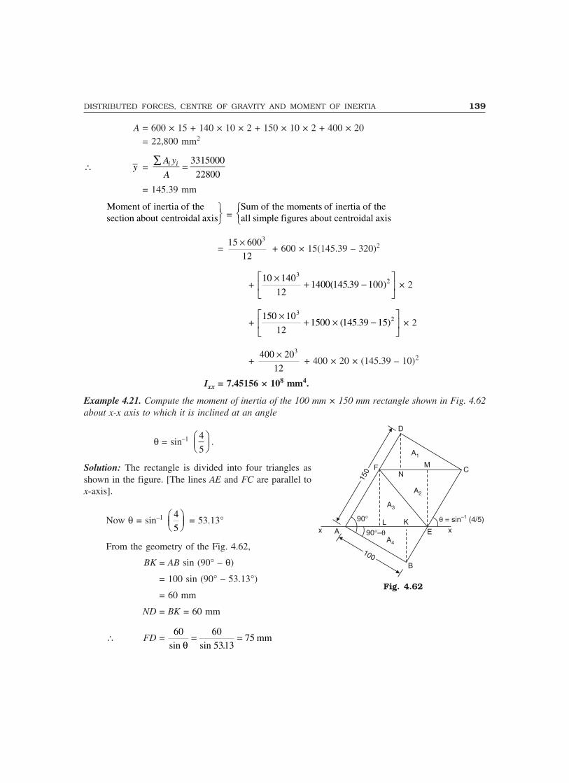
DISTRIBUTED FORCES, CENTRE OF GRAVITY AND MOMENT OF INERTIA 139
A = 600 × 15 + 140 × 10 × 2 + 150 × 10 × 2 + 400 × 20= 22,800 mm2
∴ y = 3315000
22800i iA y
A�
= 145.39 mm
Moment of inertia of thesection about centroidal axis
��
= Sum of the moments of inertia of theall simple figures about centroidal axis��
= 315 600
12
� + 600 × 15(145.39 – 320)2
+ 10 140
121400 145 39 100
32×
+ −�
��
�
��( . ) × 2
+ 150 10
121500 145 39 15
32×
+ × −�
��
�
��( . ) × 2
+ 3400 20
12
� + 400 × 20 × (145.39 – 10)2
Ixx = 7.45156 × 108 mm4.
Example 4.21. Compute the moment of inertia of the 100 mm × 150 mm rectangle shown in Fig. 4.62about x-x axis to which it is inclined at an angle
θ = sin–1 4
5� �� �� .
Solution: The rectangle is divided into four triangles asshown in the figure. [The lines AE and FC are parallel tox-axis].
Now θ = sin–1 4
5� �� �� = 53.13°
From the geometry of the Fig. 4.62,
BK = AB sin (90° – θ)
= 100 sin (90° – 53.13°)
= 60 mm
ND = BK = 60 mm
∴ FD = 60
sinmm
θ= =60
531375
sin .
Fig. 4.62
D
C
A1
MN
A2
A3
K
150
150
90°
90°–�A4
E xx A
100100
� = sin (4/5)–1
F
B
L
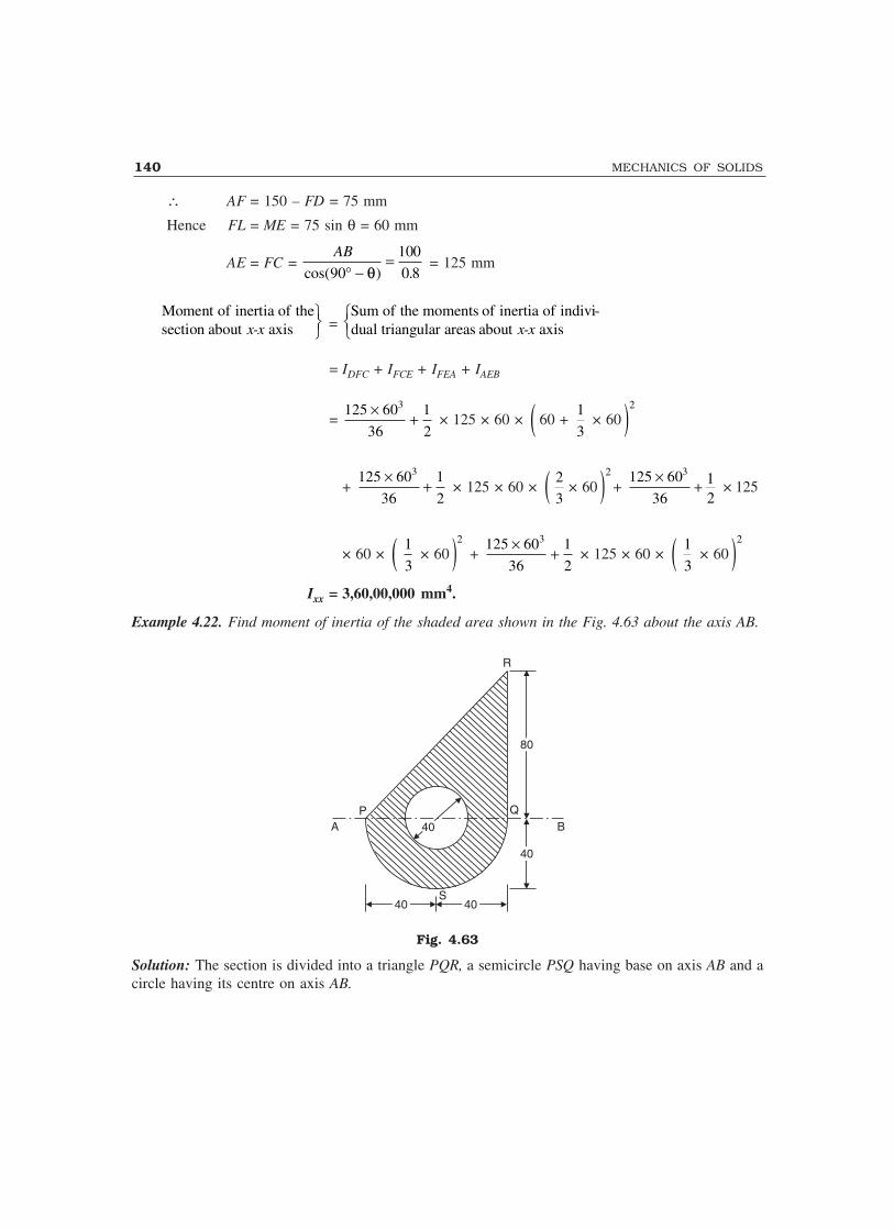
140 MECHANICS OF SOLIDS
∴ AF = 150 – FD = 75 mm
Hence FL = ME = 75 sin θ = 60 mm
AE = FC = AB
cos( ) .90
100
0 8° −=
θ = 125 mm
Moment of inertia of thesection about axisx-x
��
=Sum of the moments of inertia of indivi-dual triangular areas about axisx-x��
= IDFC + IFCE + IFEA + IAEB
=3125 60 1
36 2
�� × 125 × 60 × � 60 +
1
3 × 60 �
2
+ 3125 60 1
36 2
�� × 125 × 60 × � 2
3× 60 �
2
+ 3125 60
36
�+ 1
2× 125
× 60 × � 1
3 × 60 �
2
+ 3125 60 1
36 2
�� × 125 × 60 × � 1
3 × 60 �
2
Ixx = 3,60,00,000 mm4.
Example 4.22. Find moment of inertia of the shaded area shown in the Fig. 4.63 about the axis AB.
R
8080
QBA
P
4040
4040
S4040 4040
Fig. 4.63
Solution: The section is divided into a triangle PQR, a semicircle PSQ having base on axis AB and acircle having its centre on axis AB.
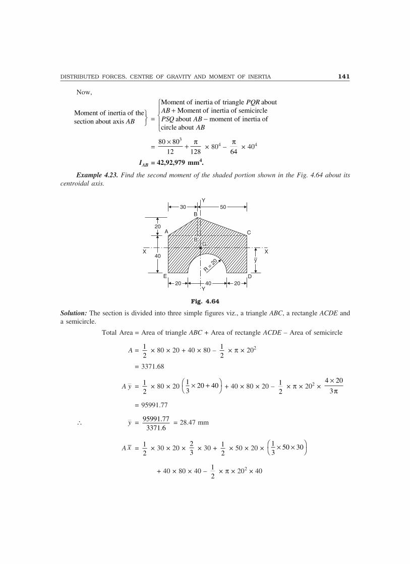
DISTRIBUTED FORCES, CENTRE OF GRAVITY AND MOMENT OF INERTIA 141
Now,
Moment of inertia of thesection about axis AB
��
=
Moment of inertia of triangle aboutMoment of inertia of semicircle
about moment of inertia ofcircle about
PQRABPSQ AB
AB
+−
�
�
=380 80
12 128
� �� × 804 –
64
� × 404
IAB = 42,92,979 mm4.
Example 4.23. Find the second moment of the shaded portion shown in the Fig. 4.64 about itscentroidal axis.
Y3030 5050
B
2020
4040X X
B�B�GG
–y–y
DER
=20
2020 20204040Y
A C
Fig. 4.64
Solution: The section is divided into three simple figures viz., a triangle ABC, a rectangle ACDE anda semicircle.
Total Area = Area of triangle ABC + Area of rectangle ACDE – Area of semicircle
A = 12
× 80 × 20 + 40 × 80 – 12
× π × 202
= 3371.68
A y = 12
× 80 × 20 1 20 403
� �� �� + 40 × 80 × 20 – 12
× π × 202 × 4 20
3
��
= 95991.77
∴ y = 95991.773371.6
= 28.47 mm
A x = 12
× 30 × 20 × 23
× 30 + 12
× 50 × 20 × 1 50 303
� �� ��
+ 40 × 80 × 40 – 12
× π × 202 × 40
142 MECHANICS OF SOLIDS
= 132203.6
∴ x = 132203.63371.68
AxA
= 37.21 mm
Moment of inertia aboutcentroidal axisx-x
��
=
Moment of inertia of triangle aboutaxis Moment of inertia of rectangle
about axis moment of semicircleabout axis
ABCx-x
x-xx-x
+−
�
�
∴ Ixx = 380 20
36
� +
1
2 × 80 × 20 � 60 –
2
3 × 20 – 28.47 �
2
+ 380 40
12
� + 80 × 40 × (28.47 – 20)2
– 0 0068598 201
220 28
4 20
34 2
2
. .47× + × − ×��
��
�
��
�
��π
π
Ixx = 6,86,944 mm4.
Similarly, Iyy = 320 30 1
36 2
�� × 20 × 30 � 39.21 –
2
3 × 30 �
2
+ 320 50
36
�
1
2� × 20 × 50 ×
����
39.21 – � 30 + 1
3 × 50 �
2����
+ 340 80
12
�
+ 40 × 80(39.21 – 40)2 – 1
2 64
�� × 404 –
1
2 ×
4�
× 402 (40 – 39.21)2
= 1868392 mm4.
4.8 THEOREMS OF PAPPUS-GULDINUS
There are two important theorems, first proposed by Greek scientist (about 340 AD) and then restatedby Swiss mathematician Paul Guldinus (1640) for determining the surface area and volumes generatedby rotating a curve and a plane area about a non-intersecting axis, some of which are shown inFig. 4.65. These theorems are known as Pappus-Guldinus theorems.

DISTRIBUTED FORCES, CENTRE OF GRAVITY AND MOMENT OF INERTIA 143
y
x
y
x
y
x
y
x
y
x
y
x
A B
(a) Cylinder Solid cylinder
(b) Cone Solid cone
(c) General curve General solid
A
B
y = kx2
(d) Sphere Solid sphere
A B
Semicircle
B
A
(e) TorusGenerating surface of revolution
Solid TorusGenerating solid of revolution
y
x
Fig. 4.65
Theorem IThe area of surface generated by revolving a plane curve about a non-intersecting axis in the planeof the curve is equal to the length of the generating curve times the distance travelled by the centroidof the curve in the rotation.
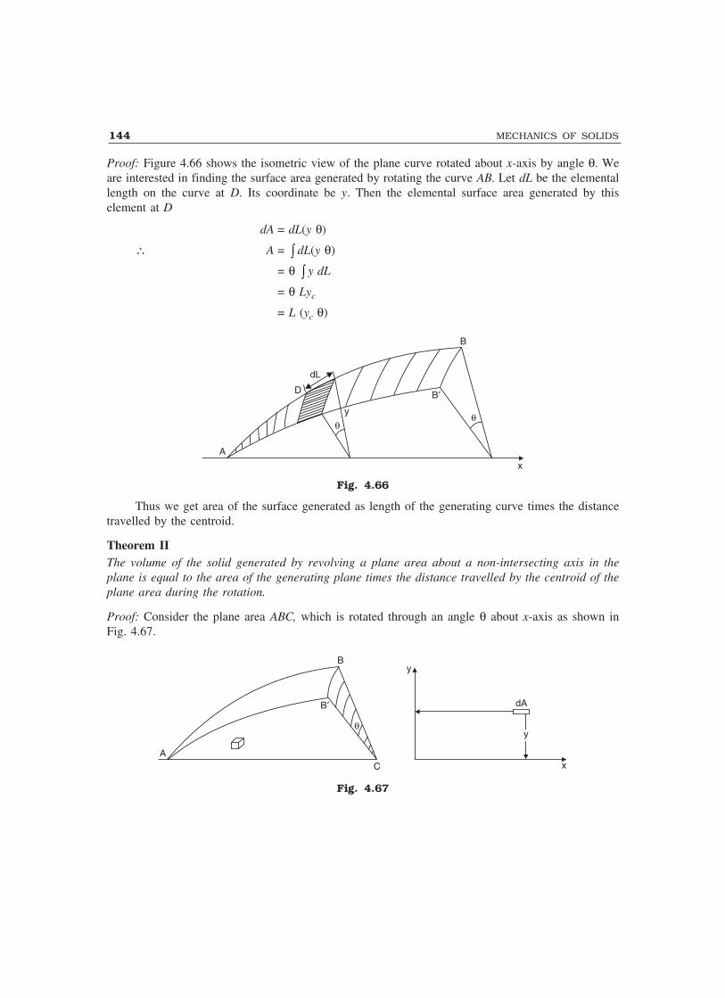
144 MECHANICS OF SOLIDS
Proof: Figure 4.66 shows the isometric view of the plane curve rotated about x-axis by angle θ. Weare interested in finding the surface area generated by rotating the curve AB. Let dL be the elementallength on the curve at D. Its coordinate be y. Then the elemental surface area generated by thiselement at D
dA = dL(y θ)
∴ A = � dL(y θ)
= θ � y dL
= θ Lyc
= L (yc θ)
A
�y
D
dL
B
B�
�
x
Fig. 4.66
Thus we get area of the surface generated as length of the generating curve times the distancetravelled by the centroid.
Theorem IIThe volume of the solid generated by revolving a plane area about a non-intersecting axis in theplane is equal to the area of the generating plane times the distance travelled by the centroid of theplane area during the rotation.
Proof: Consider the plane area ABC, which is rotated through an angle θ about x-axis as shown inFig. 4.67.
B
B�
C
�
A
y
x
yy
dA
Fig. 4.67

DISTRIBUTED FORCES, CENTRE OF GRAVITY AND MOMENT OF INERTIA 145
Let dA be the elemental area of distance y from x-axis. Then the volume generated by this areaduring rotation is given by
dV = dA/yθ∴ V = � dA/yθ
= θ � y dA
= θ A yc
= A(yc θ)
Thus the volume of the solid generated is area times the distance travelled by its centroid duringthe rotation. Using Pappus-Guldinus theorems surface area and volumes of cones and spheres can becalculated as shown below:
(i) Surface area of a cone: Referring to Fig. 4.68(a),Length of the line generating cone = L
Distance of centroid of the line from the axis of rotation = y = 2
R
In one revolution centroid moves by distance = 2πy = πR∴ Surface area = L × (πR) = πRL
(ii) Volume of a cone: Referring to Fig. 4.68(b),
Area generating solid cone = 1
2hR
Centroid G is at a distance y = 3
R
L/2
L/2
G
y = R/2y = R/2
hh
RR
x
GG
y = R/31y = R/31
RR
(a) (b)
Fig. 4.68
∴ The distance moved by the centroid in one revolution = 2πy = 2π3
R
∴ Volume of solid cone = 1
2hR ×
2
3
R�
= 2
3
R h�
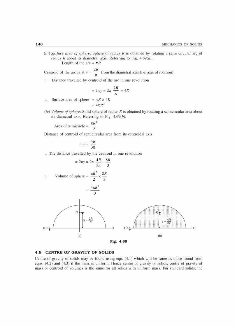
146 MECHANICS OF SOLIDS
(iii) Surface area of sphere: Sphere of radius R is obtained by rotating a semi circular arc ofradius R about its diametral axis. Referring to Fig. 4.69(a),
Length of the arc = πR
Centroid of the arc is at y = 2R
� from the diametral axis (i.e. axis of rotation)
∴ Distance travelled by centroid of the arc in one revolution
= 2πy = 2π 2R
� = 4R
∴ Surface area of sphere = π R × 4R
= 4π R2
(iv) Volume of sphere: Solid sphere of radius R is obtained by rotating a semicircular area aboutits diametral axis. Referring to Fig. 4.69(b).
Area of semicircle = 2
2
R�
Distance of centroid of semicircular area from its centroidal axis
= y = 4
3
R
�
∴ The distance travelled by the centroid in one revolution
= 2πy = 2π 4 8
3 3
R R�
�
∴ Volume of sphere = 2
� �
2 3
R R�
= 34
3
R�
x x
G
y = 2R�
x x
GG
y = 4R3�
(a) (b)
Fig. 4.69
4.9 CENTRE OF GRAVITY OF SOLIDS
Centre of gravity of solids may be found using eqn. (4.1) which will be same as those found fromeqns. (4.2) and (4.3) if the mass is uniform. Hence centre of gravity of solids, centre of gravity ofmass or centroid of volumes is the same for all solids with uniform mass. For standard solids, the

DISTRIBUTED FORCES, CENTRE OF GRAVITY AND MOMENT OF INERTIA 147
centre of gravity may be found from first principle and the results obtained for standard solids maybe used to find centre of gravity of composite solids. The procedure is illustrated with examples 4.24to 4.27.Example 4.24. Locate the centre of gravity of the right circular cone of base radius r and height hshown in Fig. 4.70.
O C
Z
Dx
B
Y z
h
dx
A
Axis ofrotation
X
r
Fig. 4.70
Solution: Taking origin at the vertex of the cone and selecting the axis as shown in Fig. 4.70, it canbe observed that due to symmetry the coordinates of centre of gravity y and z are equal to zero, i.e.the centre of gravity lies on the axis of rotation of the cone. To find its distance x from the vertex,consider an elemental plate at a distance x. Let the thickness of the elemental plate be dx. From thesimilar triangles OAB and OCD, the radius of elemental plate z is given by
z = x
hr
∴ Volume of the elemental plate dv
dv = πz2 dx = πx2 2
2
r
h dx
If γ is the unit weight of the material of the cone, then weight of the elemental plate is given by:
dW = γ�π�x22
2
r
hdx ...(i)
W = 0
h
�2
2
r
h
�� x2 dx
= γ 2 3
203
hr x
h
� ��� �
= γ π2
3
r h...(ii)
Note:πr h2
3is volume of cone
�
��
�
��
Now, substituting the value of dW in (i), above, we get:
� x . dW = 0
h
� γ 2
2
r
h
� x2 ⋅ x ⋅ dx

148 MECHANICS OF SOLIDS
= γ2 4
204
hr x
h
� ��� �
= γ 2 2
4
r h�...(iii)
From eqn. 4.1,W x = � x dW
i.e.,2
3
r h�x =
2 2
4
r h��
∴ x = 3
4h
Thus, in a right circular cone, centre of gravity lies at a distance 3
4h from vertex along the axis
of rotation i.e., at a distance 4
h from the base.
Example 4.25. Determine the centre of gravity of a solid hemisphere of radius r from its diametralaxis.
Solution: Due to symmetry, centre of gravity lies on the axis of rotation. To find its distance x fromthe base along the axis of rotation, consider an elemental plate at a distance x as shown in Fig. 4.71.
Now, x2 + z2 = r2
z2 = r2 – x2 ...(i)Volume of elemental plate
dv = πz2 dx = π(r2 – x2)dx ...(ii)∴ Weight of elemental plate
dW = γdv = γπ(r2 – x2)dx ...(iii)∴ Weight of hemisphere
W = � dW = 0
r
� γπ(r2 – x2)dx
= γπ 2
2
03
rx
r x� �
�� �
= 32
3
r��...(iv)
Moment of weight about z axis
= 0
r
� xdW
xO x
zr
dwz
Fig. 4.71
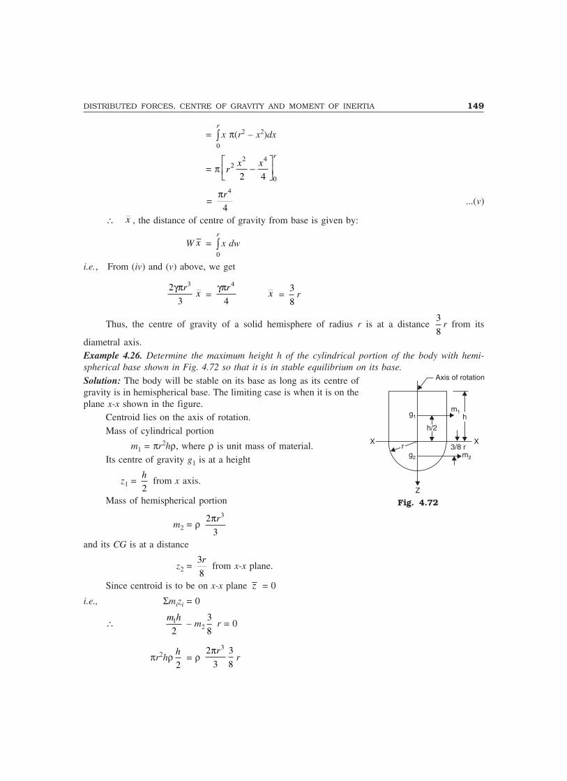
DISTRIBUTED FORCES, CENTRE OF GRAVITY AND MOMENT OF INERTIA 149
= 0
r
� x π(r2 – x2)dx
= π2 4
2
02 4
rx x
r� �
�� �
= 4
4
r�...(v)
∴ x , the distance of centre of gravity from base is given by:
W x = 0
r
� x dw
i.e., From (iv) and (v) above, we get
32
3
r��x =
4
4
r��x =
3
8r
Thus, the centre of gravity of a solid hemisphere of radius r is at a distance 3
8r from its
diametral axis.Example 4.26. Determine the maximum height h of the cylindrical portion of the body with hemi-spherical base shown in Fig. 4.72 so that it is in stable equilibrium on its base.
Solution: The body will be stable on its base as long as its centre ofgravity is in hemispherical base. The limiting case is when it is on theplane x-x shown in the figure.
Centroid lies on the axis of rotation.Mass of cylindrical portion
m1 = πr2hρ, where ρ is unit mass of material.Its centre of gravity g1 is at a height
z1 = 2
h from x axis.
Mass of hemispherical portion
m2 = ρ 32
3
r�
and its CG is at a distance
z2 = 3
8
r from x-x plane.
Since centroid is to be on x-x plane z = 0
i.e., Σmizi = 0
∴ 1
2
m h– m2
3
8 r = 0
πr2hρ2
h= ρ
32 3
3 8
r�r
Axis of rotation
g1m1
h
h/2
rX X
3/8 rg2 m2
Z
Fig. 4.72

150 MECHANICS OF SOLIDS
∴ h2 = 1
2r2
or h = r
2 = 0.707 r
Example 4.27. A concrete block of size 0.60 m × 0.75 m × 0.5 m is cast with a hole of diameter 0.2m and depth 0.3 m as shown in Fig. 4.73. The hole is completely filled with steel balls weighing 2500N. Locate the centre of gravity of the body. Take the weight of concrete = 25000 N/m3.
0.75 m0.5 m
X
0.4m
0.4m0.2 m0.2 m
0.6m
0.6m
0.3 m
0.5 m
Z
Y
Fig. 4.73
Solution: Weight of solid concrete block:
W1 = 0.6 × 0.75 × 0.5 × 25000 = 5625 NWeight of concrete (W2) removed for making hole:
W2 = 4
�
× 0.22 × 0.3 × 25000 = 235.62 N
Taking origin as shown in the figure, the centre of gravity of solid block is (0.375, 0.3, 0.25) andthat of hollow portion is (0.5, 0.4, 0.15). The following table may be prepared now:
Table
Simple Body Wi xi Wixi yi Wiyi zi Wizi
1. Solid block 5625 0.375 2109.38 0.3 1687.5 0.25 1406.252. Hole in concrete –235.62 0.5 –117.81 0.4 –94.25 0.15 –35.34
block3. Steel balls 2500 0.5 1250.0 0.4 1000.0 0.15 375.0
ΣWi = 7889.38 ΣWixi = 3241.57 ΣWiyi = 2593.25 ΣWizi = 1745.91
∴ x = i i i i
i
W x W x
W W�
x = 3241.577889.38
= 0.411 m
Similarly, y = 2593.257887.38
= 0.329 m
z = 1745.917889.38
= 0.221 m

DISTRIBUTED FORCES, CENTRE OF GRAVITY AND MOMENT OF INERTIA 151
IMPORTANT FORMULAE
1. Area of sector of a circle = R2 α2. Area of parabolic spandrel
(i) if y = kx2, A = 1
3ha = 1
3 × the area of rectangle of size a × h
(ii) if y2 = kx, A = 2
3ha =
2
3 × the area of rectangle of size a × h.
3. Surface area of the cone = πRl
4. Surface area of the sphere = 4πR2
5. Volume of a cone = 2
�
3
R h
6. Volume of a sphere = 4
3 πR3
7. Centroid of a arc of a circle is at xc = R sin α
α from the centre of circle on the symmetric axis.
8. Centroid of a composite figure is given by
xc = ΣA x
Ai i , yc =
ΣA y
Ai i .
9. Centroid of simple figure from the reference axis
yy dA
A= � .
10. For centroid of standard figures refer Table 4.2.
11. Iyy = Σxi2 dAi and Ixx = Σyi
2 dAi, Izz = Σri2dAi = r dA2� .
12. Radius of gyration k = I
Ai.e. I = Ak2.
13. Izz = Ixx+ Iyy.14. IAB = IGG + Ayc
2.
15. Moment of inertia of standard sections are as shown in Table 4.4.16. Pappus-Guldinus Theorems:
(i) The area of surface generated by revolving a plane curve about a non-intersecting axis inthe plane of the curve is equal to the length of the generating curve times the distancetravelled by the centroid of the curve in the rotation.
(ii) The volume of the solid generated by a plane area about a non-intersecting axis in theplane is equal to the area of the generating plane times the distance travelled by the centroidof the plane area during the rotation.

152 MECHANICS OF SOLIDS
17. In a right circular cone, the centre of gravity lies at a distance 3
4 × height from the vertex along
the axis of rotation.
18. The centre of gravity of a solid hemisphere of radius r is at a distance 3
8 × r from its diametral
axis.
THEORY QUESTIONS
1. Determine the centroid of an arc of radius R from first principle.
2. Distinguish between centroid and centre of gravity.3. Determine the centroid of a triangle of base width ‘b’ and height ‘h’ by the method of
integration.4. Locate the centroid of a semicircle from its diametral axis using the method of integration.
5. Explain the terms moment of inertia and radius of gyration of a plane figure.6. State and prove
(a) Perpendicular axis theorem(b) Parallel axis theorem of moment of inertia.
7. Determine the moment of inertia of the areas specified below by first principle:(i) Triangle of base width b and height h about its centroid axis parallel to the base.
(ii) A semicircle about its centroidal axis parallel to the diametral axis.
8. State and explain theorems of Pappus-Guldinus.9. Locate the centre of gravity of the right circular cone of base radius R and height h.
10. Determine the centre of gravity of a solid hemisphere of radius R from its diametral axis.
PROBLEMS FOR EXERCISE
1. Determine the centroid of the built-up section in Fig. 4.74. Express the coordinates of centroidwith respect to x and y axes shown. [Ans. x = 48.91 mm; y = 61.30 mm]
100100
20
10
8080
10y
4040 10 2020
2020xO
120120
Fig. 4.74

DISTRIBUTED FORCES, CENTRE OF GRAVITY AND MOMENT OF INERTIA 153
2. Determine the centroid of the reinforced concrete retaining wall section shown in Fig. 4.75.
[Ans. x = 1.848 m; y = 1.825 m]
0.3 m
6.0 m6.0 m
y
O
1.4 m1.4 m 2.1 m2.1 m0.5
0.6 mx
Fig. 4.75
3. Find the coordinates of the centroid of the shaded area with respect to the axes shown inFig. 4.76. [Ans. x = 43.98 mm; y = 70.15 mm]
6060 6060
6060
8080
y
4040 8080X
R=
80
Fig. 4.76
4. A circular plate of uniform thickness and of diameter 500 mm as shown in Fig. 4.77 has twocircular holes of 40 mm diameter each. Where should a 80 mm diameter hole be drilled so thatthe centre of gravity of the plate will be at the geometric centre.
[Ans. x = 50 mm; y = 37.5 mm]

154 MECHANICS OF SOLIDS
200200
40D=500D=500
150150
4040
X
Y
Fig. 4.77
5. With respect to the coordinate axes x and y locate the centriod of the shaded area shown inFig. 4.78. [Ans. x = 97.47 mm; y = 70.77 mm]
Y
100100
30305050
3030
7070
R=5
0
100100 100100X
Fig. 4.78
6. Locate the centroid of the plane area shown in Fig. 4.79.
[Ans. x = 104.10 mm; y = 44.30 mm]
R=5
0R=3
045458080
y 8080
X225225
Fig. 4.79
7. Determine the coordinates of the centroid of shaded as shown in Fig. 4.80 with respect to thecorner point O. Take x = 40 mm. [Ans. x = 260.07 mm; y = 113.95 mm]

DISTRIBUTED FORCES, CENTRE OF GRAVITY AND MOMENT OF INERTIA 155
2x2x 2x2x2x2x 6x6x
2x2x
2x2x
3x3x
2x2x
2x2x
3x3x
X
Y2x2x
R=3x
r=2x
r=2x
Fig. 4.80
8. ABCD is a square section of sides 100 mm. Determine the ratio of moment of inertia of thesection about centroidal axis parallel to a side to that about diagonal AC. [Ans. 1]
9. The cross-section of a rectangular hollow beam is as shown in Fig. 4.81. Determine the polarmoment of inertia of the section about centroidal axes.
[Ans. Ixx = 1,05,38,667 mm4; Iyy = 49,06,667 mm4; Izz = 1,54,45,334 mm4]
2020 20204040
8080
2020
4040
6060
120120
Fig. 4.81
10. The cross-section of a prestressed concrete beam is shown in Fig. 4.82. Calculate the momentof inertia of this section about the centroidal axes parallel to and perpendicular to top edge.Also determine the radii of gyration. [Ans. Ixx = 1.15668 × 1010 mm4; kxx = 231.95 mm;
Iyy = 8.75729 × 109 mm4; kyy = 201.82 mm]
10001000
100
150 350350
250250
250250
Fig. 4.82

156 MECHANICS OF SOLIDS
11. The strength of a 400 mm deep and 200 mm wide I-beam of uniform thickness 10 mm, isincreased by welding a 250 mm wide and 20 mm thick plate to its upper flanges as shown inFig. 4.83. Determine the moment of inertia and the radii of gyration of the composite sectionwith respect to cetroidal axes parallel to and perpendicular to the bottom edge AB.
[Ans. Ixx = 3.32393 × 108 mm4; kxx = 161.15 mm;Iyy = 3,94,06,667 mm4; kyy = 55.49 mm]
25025020
10
10
400400
A10
B200200
Fig. 4.83
12. The cross-section of a gantry girder is as shown in Fig. 4.84. It is made up of an I-section ofdepth 450 mm, flange width 200 mm and a channel of size 400 mm × 150 mm. Thickness ofall members is 10 mm. Find the moment of inertia of the section about the horizontal centroidaxis. [Ans. Ixx = 4.2198 × 108 mm4]
400400
15015010
10 450450
200200
Fig. 4.84
13. A plate girder is made up of a web plate of size 400 mm × 10 mm, four angles of size 100mm × 100 mm × 10 mm and cover plates of size 300 mm × 10 mm as shown in Fig. 4.85.Determine the moment of inertia about horizontal and vertical centroidal axes.
[Ans. Ixx = 5.35786 × 108 mm4; Iyy = 6,08,50,667 mm4]

DISTRIBUTED FORCES, CENTRE OF GRAVITY AND MOMENT OF INERTIA 157
300300
10
10
400400
4 equalangles of size
100 × 100 × 10 mm
Fig. 4.85
14. Determine the moment of inertia and radii of gyration of the area shown in Fig. 4.86 aboutthe base A-B and the centroidal axis parallel to AB.
[Ans. IAB = 48,15,000 mm4; Ixx = 18,24,231 mm4
kAB = 35.14 mm; kxx = 21.62 mm]
3030
3030
30302020
100100A B
Fig. 4.86
15. Determine the moment of inertia of the section shown in Fig. 4.87 about the vertical centroidalaxis. [Ans. Iyy = 5,03,82,857 mm4]
1001002020 8080
6060 6060120120
Fig. 4.87

158 MECHANICS OF SOLIDS
16. A semi-circular cut is made in rectangular wooden beam as shown in Fig. 4.88. Determine thepolar moment of inertia of the section about the centroidal axis.
[Ans. Ixx = 3,35,81,456 mm4; Iyy = 1,00,45,631 mm4; Izz = 2,20,98,980 mm4]
150150
100100
Fig. 4.88
17. Determine the moment of inertia of the section shown in the Fig. 4.89 about the horizontalcentroidal axis. Also find the moment of inertia of the section about the symmetrical axis.Hence find the polar moment of inertia.
[Ans. Ixx = 54,09,046 mm4; Iyy = 14,55,310 mm4; Izz = 68,64,356 mm4]
Semicircle
r = 40
3030 3030
100100
Fig. 4.89
18. The cross-section of a machine part is as shown in Fig. 4.90. Determine its moment of inertiaand radius of gyration about the horizontal centroidal axis.
[Ans. Ixx = 5249090.85 mm4; kxx = 27.05 mm]

DISTRIBUTED FORCES, CENTRE OF GRAVITY AND MOMENT OF INERTIA 159
O
r = 60
100100
100100
Fig. 4.90
19. The cross-section of a plain concrete culvert is as shown in Fig. 4.91. Determine the momentof inertia about the horizontal centroidal axes. [Ans. Ixx = 5.45865 × 1010 mm4]
400400 40040010001000
10001000
r =65
0
Fig. 4.91
20. Determine the centroid of the built-up section shown in Fig. 4.92 and find the moment ofinertia and radius of gyration about the horizontal centroidal axis.
[Ans. Ixx = 1267942 mm4; kxx = 18.55 mm]
2020
20202020
2020
20202020 4040
r =20
4040
Fig. 4.92
21. Determine the centre of gravity of the pyramid shown in Fig. 4.93. Ans. x h=���
���
34
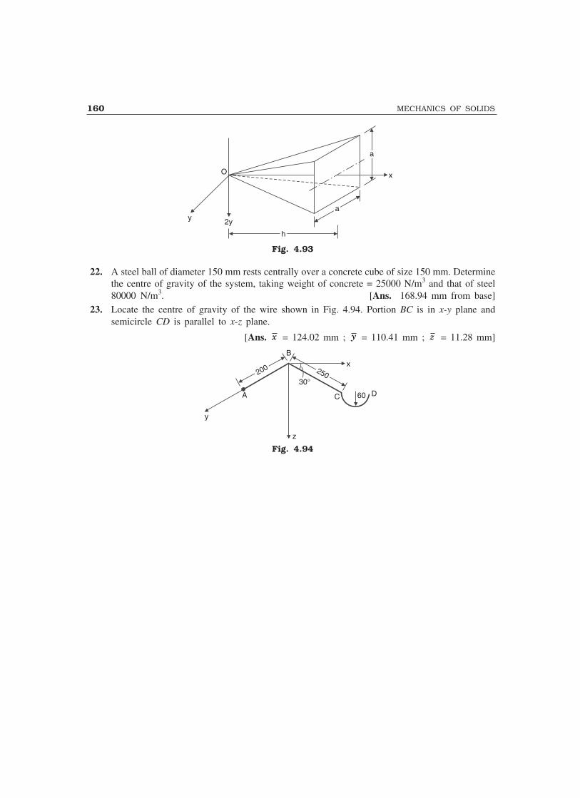
160 MECHANICS OF SOLIDS
y 2y
hh
aa
aa
xO
Fig. 4.93
22. A steel ball of diameter 150 mm rests centrally over a concrete cube of size 150 mm. Determinethe centre of gravity of the system, taking weight of concrete = 25000 N/m3 and that of steel80000 N/m3. [Ans. 168.94 mm from base]
23. Locate the centre of gravity of the wire shown in Fig. 4.94. Portion BC is in x-y plane andsemicircle CD is parallel to x-z plane.
[Ans. x = 124.02 mm ; y = 110.41 mm ; z = 11.28 mm]
D60C
30°
250250x
B
200200
A
y
z
Fig. 4.94

5Friction
When a body moves or tends to move over another body, a force opposing the motion develops at thecontact surfaces. The force which opposes the movement or the tendency of movement is called thefrictional force or simply friction. So far, in earlier chapters, we had ignored this force and consideredcontacting surfaces are smooth. Actually in almost all cases the contacting surfaces are not smooth.There are minutely projecting particles which develop frictional force to oppose the tendency tomovement of one surface over the other surface. In this chapter, the additional terminology used inconnection with frictional forces are explained and laws of dry friction (wet friction excluded) arepresented. Applications of these laws to many engineering problems are illustrated.
5.1 COEFFICIENT OF FRICTION
Whenever a resultant force acts in the direction of contacting surfaces frictional force develops tooppose that force. The frictional force, like any other reaction, has a remarkable property of adjustingitself in magnitude to the tangential force. However, there is a limit beyond which the magnitude ofthe frictional force will not develop. If the applied tangential force is more than this maximumfrictional force, there will be movement of one body over the other body with an acceleration as perNewton’s second law of mass times acceleration equal to the resultant force. This maximum value offrictional force, which comes into play when the motion is impending is known as Limiting Friction.It may be noted that when the applied tangential force is less than the limiting friction, the bodyremains at rest and such friction is called Static Friction, which will have any value between zero andlimiting friction. If the value of applied tangential force exceeds the limiting friction, the body startsmoving over another body and the frictional resistance experienced while moving is known as DynamicFriction. The magnitude of dynamic friction is found to be less than limiting friction. Dynamicfriction may be further classified into two groups:
(i) Sliding Friction: It is the friction experienced by a body when it slides over the otherbody.
(ii) Rolling Friction: It is the friction experienced by a body when it rolls over another body.
It has been experimentally proved that, between two contacting surfaces, the magnitude of limitingfriction bears a constant ratio to the normal reaction between the two and this ratio is called ‘Coefficient
161

162 MECHANICS OF SOLIDS
of Friction’. Referring to Fig. 5.1 a body weighing W is beingpulled by a force P and the motion is impending. Let N benormal reaction and F the limiting frictional force. Then
Coefficient of Friction = F
N
Coefficient of friction is denoted by µ. Then
µ = F
N...(5.1)
5.2 LAWS OF FRICTION
The principles discussed in a previous article are mainly due to the experiemental studies by Coulomb(1781) and by Mozin (1831). These principles constitute the laws of dry friction and may be called asCoulomb’s laws of dry friction. These laws are listed below:
(i) The frictional force always acts in a direction opposite to that in which the body tends tomove.
(ii) Till the limiting value is reached, the magnitude of frictional force is exactly equal to thetangential force which tends to move the body.
(iii) The magnitude of the limiting friction bears a constant ratio to the normal reaction betweenthe two contacting surfaces.
(iv) The force of friction depends upon the roughness/smoothness of the surfaces.
(v) The force of friction is independent of the area of contact between the two surfaces.
(vi) After the body starts moving, the dynamic friction comes into play, the magnitude of whichis less than that of limiting friction and it bears a constant ratio to the normal force. Thisratio is called coefficient of dynamic friction.
5.3 ANGLE OF FRICTION, ANGLE OF REPOSE AND CONE OF FRICTION
Angle of Friction
Consider the block shown in Fig. 5.2 subject to pull P. Let F bethe frictional force developed and N the normal reaction. Thus,at contact surface, the reactions are F and N. They can becombined to get the resultant reaction R which acts at angle θto normal reaction. This angle is given by
tan θ = F
N
As frictional force increases the angle θ increases and it canreach maximum value � when limiting value of friction isreached. Thus, when motion is impending
Fig. 5.1
Fig. 5.2
W
P
F
N
R�
F
W
P
F
N

FRICTION 163
tan α = F
N = µ ...(5.2)
and this value of α is called angle of limiting friction. Hence, the angle of limiting friction can bedefined as the angle between the resultant reaction and the normal to the plane on which the motion ofthe body is impending.
Angle of Repose
It is very well-known that when grains (food grains, sand, cement, soil etc.) are heaped, there exists alimit for the inclination of the heap. Beyond that the grains start rolling down. The limiting angle up towhich the grains repose (sleep) is called angle of repose.
Now consider the block of weight W shown in Fig. 5.3 which is resting on an inclined plane thatmakes angle θ with the horizontal. When θ is a small, block rests on the plane. If θ is increasedgradually a stage is reached at which the block starts sliding. The angle made by the plane with thehorizontal is called angle of friction for the contacting surfaces. Thus, the maximum inclination of theplane on which the body, free from external forces, can repose is called angle of repose.
Consider the equilibrium of the block shown in Fig. 5.3. Since the surface of contact is not smooth,not only normal reaction but frictional force also develops. As the body tends to slide down, thefrictional resistance will be up the plane.
Σ Forces normal to plane = 0, gives
N = W cos θ ...(i)
Σ Forces parallel to plane = 0, gives
F = W sin θ ...(ii)
Dividing eqn. (ii) by eqn. (i) we get,
F
N= tan θ
If φ is the value of θ when motion is impending, frictional force will be limiting friction and hence
tan φ = F
N...(5.3)
i.e., tan φ = µ = tan α
or φ = α.
Thus, the value of angle of repose is the same as the value of limiting angle of friction.
Cone of Friction
When a body is having impending motion in the direction of P, the frictional force will be the limitingfriction and the resultant reaction R will make limiting frictional angle � with the normal as shown in
Fig. 5.3

164 MECHANICS OF SOLIDS
Fig. 5.4. If the body is having impending motion in some otherdirection, the resultant reaction makes limiting frictional angle� with the normal. Thus, if the direction of force P is graduallychanged through 360°, the resultant R generates a right circularcone with semicentral angle equal to �.
If the resultant reaction lies on the surface of this invertedright circular cone whose semicentral angle is limiting frictionalangle �, the motion of the body is impending. If the resultant iswithin this cone the body is stationary. This inverted cone withsemicentral angle, equal to limiting frictional angle �, is calledcone of friction.
5.4 PROBLEMS ON BLOCKS RESTING ON HORIZONTAL AND INCLINED PLANES
Analysis of such problems, when motion is impending is illustrated in this article by solving typicalproblems.
Example 5.1. Block A weighing 1000 N rests over block B which weighs 2000 N as shown inFig. 5.5(a). Block A is tied to a wall with a horizontal string. If the coefficient of friction between Aand B is 1/4 and that between B and the floor is 1/3, what value of force P is required to createimpending motion if (a) P is horizontal, (b) P acts 30° upwards to horizontal?
Solution: (a) When P is horizontal: The free body diagrams of the two blocks are shown inFig. 5.5(b). Note the frictional forces are to be marked in the opposite directions of impending relativemotion. In this problem, block B is having impending motion to the right. Hence on it F1 and F2 aretowards right. The relative motion of block A w.r.t. B is to the left. Hence the direction of F1 in this istowards the right. Another way of thinking for the direction of F1 in case of block A can be ‘actionsand reactions are equal and opposite’. Hence on block B if F1 is towards left, on A it should betowards right.
(a) (b)
Fig. 5.5
Fig. 5.4
W
F
RN
F
��
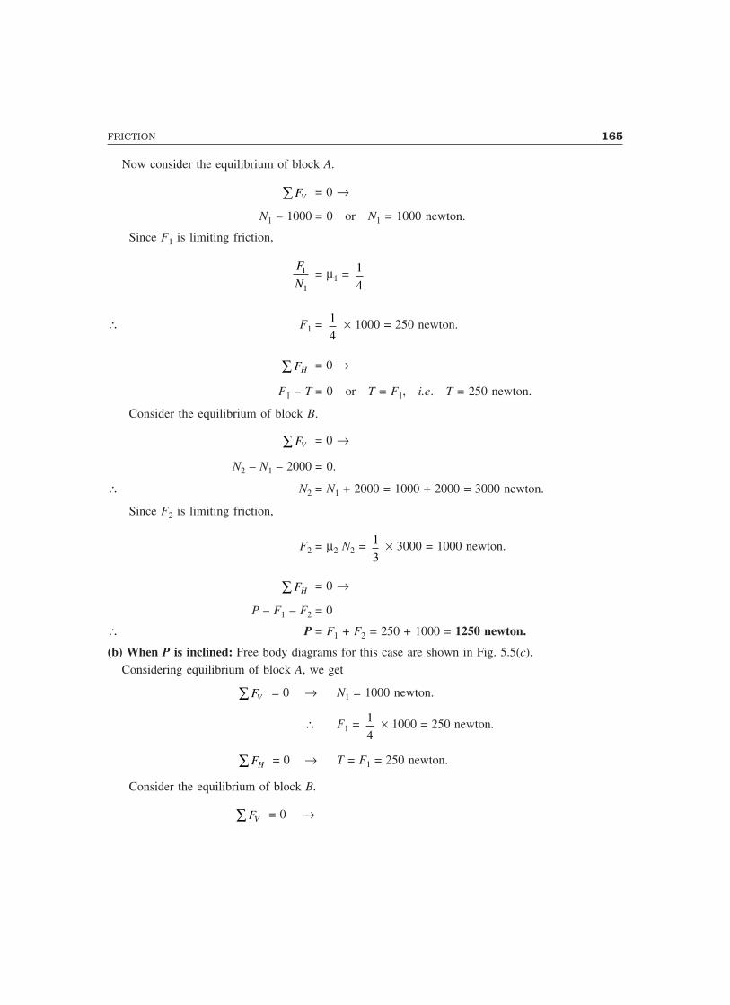
FRICTION 165
Now consider the equilibrium of block A.
VF∑ = 0 →
N1 – 1000 = 0 or N1 = 1000 newton.
Since F1 is limiting friction,
1
1
F
N= µ1 = 1
4
∴ F1 = 1
4 � 1000 = 250 newton.
HF∑ = 0 →
F1 – T = 0 or T = F1, i.e. T = 250 newton.
Consider the equilibrium of block B.
VF∑ = 0 →
N2 – N1 – 2000 = 0.
∴ N2 = N1 + 2000 = 1000 + 2000 = 3000 newton.
Since F2 is limiting friction,
F2 = µ2 N2 = 1
3 � 3000 = 1000 newton.
HF∑ = 0 →
P – F1 – F2 = 0
∴ P = F1 + F2 = 250 + 1000 = 1250 newton.
(b) When P is inclined: Free body diagrams for this case are shown in Fig. 5.5(c).Considering equilibrium of block A, we get
VF∑ = 0 → N1 = 1000 newton.
∴ F1 = 1
4 � 1000 = 250 newton.
HF∑ = 0 → T = F1 = 250 newton.
Consider the equilibrium of block B.
VF∑ = 0 →
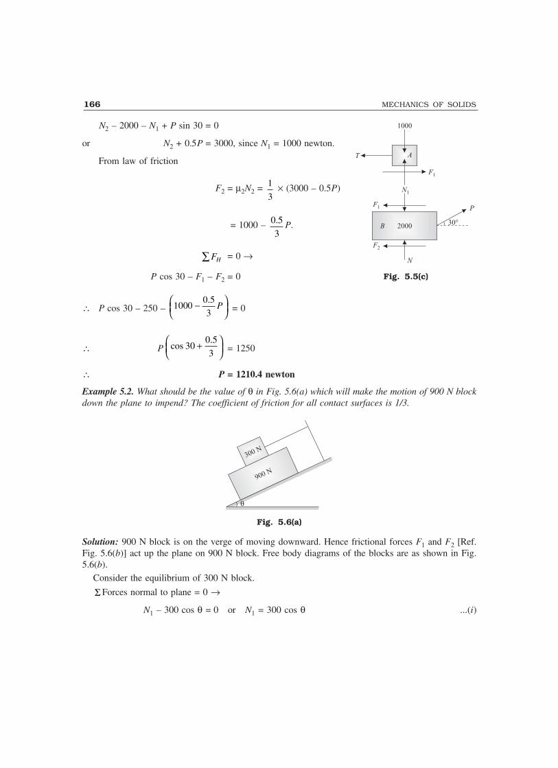
166 MECHANICS OF SOLIDS
N2 – 2000 – N1 + P sin 30 = 0
or N2 + 0.5P = 3000, since N1 = 1000 newton.
From law of friction
F2 = µ2N2 = 1
3 � (3000 – 0.5P)
= 1000 – 0.5
3P.
HF∑ = 0 →
P cos 30 – F1 – F2 = 0
∴ P cos 30 – 250 – 0.5
10003
P − = 0
∴ P0.5
cos 303
+ = 1250
∴ P = 1210.4 newton
Example 5.2. What should be the value of θ in Fig. 5.6(a) which will make the motion of 900 N blockdown the plane to impend? The coefficient of friction for all contact surfaces is 1/3.
300 N
900 N
�
Fig. 5.6(a)
Solution: 900 N block is on the verge of moving downward. Hence frictional forces F1 and F2 [Ref.Fig. 5.6(b)] act up the plane on 900 N block. Free body diagrams of the blocks are as shown in Fig.5.6(b).
Consider the equilibrium of 300 N block.
Σ Forces normal to plane = 0 →
N1 – 300 cos θ = 0 or N1 = 300 cos θ ...(i)
Fig. 5.5(c)
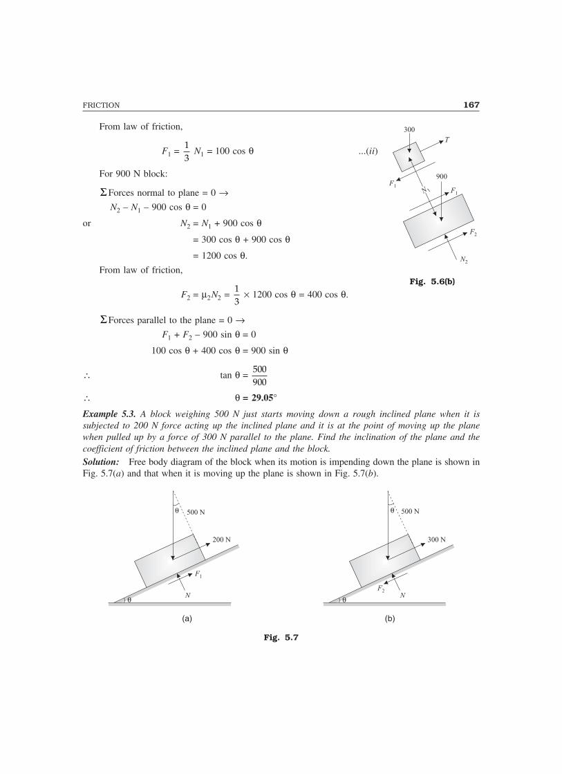
FRICTION 167
From law of friction,
F1 = 13
N1 = 100 cos θ ...(ii)
For 900 N block:
� Forces normal to plane = 0 →N2 – N1 – 900 cos θ = 0
or N2 = N1 + 900 cos θ
= 300 cos θ + 900 cos θ
= 1200 cos θ.
From law of friction,
F2 = �2N2 = 13
�� 1200 cos θ = 400 cos θ.
� Forces parallel to the plane = 0 →F1 + F2 – 900 sin θ = 0
100 cos θ + 400 cos θ = 900 sin θ
∴ tan θ = 500900
∴ θ = 29.05°
Example 5.3. A block weighing 500 N just starts moving down a rough inclined plane when it issubjected to 200 N force acting up the inclined plane and it is at the point of moving up the planewhen pulled up by a force of 300 N parallel to the plane. Find the inclination of the plane and thecoefficient of friction between the inclined plane and the block.Solution: Free body diagram of the block when its motion is impending down the plane is shown inFig. 5.7(a) and that when it is moving up the plane is shown in Fig. 5.7(b).
(a) (b)
Fig. 5.7
Fig. 5.6(b)

168 MECHANICS OF SOLIDS
When block starts moving down the plane [Ref. Fig. 5.7(a)]Frictional forces oppose the direction of the movement. Hence F1 is up the plane and F2 down the
plane. Since it is limiting case
F
N = µ.
� forces perpendicular to the plane = 0 →
N – 500 cos θ = 0 or N = 500 cos θ ...(i)
From law of friction,
F1 = µN = 500 µ cos θ ...(ii)
Σ Forces parallel to the plane = 0 →
F1 + 200 – 500 sin θ = 0
Substituting the value of F1 from eqn. (ii), we get
500 sin θ – 500 µ cos θ = 200 ...(iii)
When the block starts moving up the plane [Fig. 5.7(b)]
Σ Forces perpendicular to the plane = 0 →
N – 500 cos θ = 0 i.e., N = 500 cos θ ...(iv)
From law of friction, F2 = µN = 500 µ cos θ ...(v)
Σ Forces parallel to the plane = 0 →
300 – 500 sin θ – F2 = 0
i.e., 500 sin θ + 500 µ cos θ = 300 ...(vi)
Adding eqns. (iii) and (vi), we get
1000 sin θ = 500
i.e., sin θ = 0.5
Hence θθθθθ = 30°
Substituting it in eqn. (vi), we get
500 sin 30 + 500 µ cos 30 = 300
500 µ cos 30 = 300 – 250 = 50
∴ µ = 50
500 cos 30 = 0.115
Example 5.4. Block A weighing 1000 N and block B weighing 500 N are connected by flexible wire.The coefficient of friction between block A and the plane is 0.5 while that for block B and the plane is0.2. Determine what value of inclination of the plane the system will have impending motion down theplane? [Ref. Fig. 5.8].

FRICTION 169
(a) (b)
Fig. 5.8
Solution: Let θ be the inclination of the plane for which motion is impending. Free body diagrams ofblocks A and B are as shown in Fig. 5.8(b). Considering equilibrium of block A,
Σ Forces normal to plane = 0 →
N1 – 1000 cos θ = 0 or N1 = 1000 cos θ ...(i)
∴ From law of friction
F1 = µ1N1 = 0.5 � 1000 cos θ = 500 cos θ ...(ii)Σ Forces parallel to plane = 0 →
F1 – T – 1000 sin θ = 0
or T = 500 cos θ – 1000 sin θ ...(iii)
Consider the equilibrium of block B,
Σ Forces normal to plane = 0 →
N2 – 500 cos θ = 0 or N2 = 500 cos θ ...(iv)
From law of friction,
F2 = µ2N2 = 0.2 � 500 cos θ = 100 cos θ ...(v)
Σ Forces parallel to plane = 0 →
F2 + T – 500 sin θ = 0
Using the values of F2 and T from eqn. (v) and eqn. (iii),
100 cos θ + 500 cos θ – 1000 sin θ – 500 sin θ = 0
600 cos θ = 1500 sin θ
∴ tan θ = 600
1500
∴ θθθθθ = 21.8°

170 MECHANICS OF SOLIDS
Example 5.5. What is the value of P in the system shown in Fig. 5.9(a) to cause the motion to impend?Assume the pulley is smooth and coefficient of friction between the other contact surfaces is 0.2.
(a) (b)
Fig. 5.9
Solution: Free body diagrams of the blocks are as shown in Fig. 5.9(b). Consider the equilibrium of750 N block.
Σ Forces normal to the plane = 0 →
N1 – 750 cos 60 = 0 ∴ N1 = 375 newton ...(i)
Since the motion is impending, from law of friction,
F1 = µN1 = 0.2 � 375 = 75 newton ...(ii)
Σ Forces parallel to the plane = 0 →
T – F1 – 750 sin 60 = 0
∴ T = 75 + 750 sin 60 = 724.5 newton. ...(iii)
Consider the equilibrium of 500 N block.
VF∑ = 0 →
N2 – 500 + P sin 30 = 0
i.e., N2 + 0.5P = 500 ...(iv)
From law of friction,
F2 = µN2 = 0.2 (500 – 0.5P) = 100 – 0.1P ...(v)
HF∑ = 0 →
P cos 30 – T – F2 = 0
i.e., P cos 30 – 724.5 – 100 + 0.1P = 0
∴ P = 853.5 N

FRICTION 171
Example 5.6. Two identical planes AC and BC, inclined at 60° and 30° to the horizontal meet at C asshown in Fig. 5.10. A load of 1000 N rests on the inclined plane BC and is tied by a rope passing overa pulley to a block weighing W newtons and resting on the plane AC. If the coefficient of frictionbetween the load and the plane BC is 0.28 and that between the block and the plane AC is 0.20, findthe least and greatest values of W for the equilibrium of the system.
(a) (b)
(c)
Fig. 5.10
Solution:(a) Least value of W:In this case motion of 1000 N block is impending down the plane and block W has impending motionup the plane. Hence free body diagrams for the blocks are as shown in Fig. 5.10(b). Considering theequilibrium of 1000 N block,
Σ Forces normal to the plane = 0 →
N1 – 1000 cos 30 = 0 ∴ N1 = 866.0 newton ...(i)
From the law of friction
F1 = µ1N1 = 0.28 � 866.0 = 242.5 newton ...(ii)
Σ Forces parallel to the plane = 0 →
T – 1000 sin 30 + F1 = 0

172 MECHANICS OF SOLIDS
∴ T = 500 – 242.5 = 257.5 newton ...(iii)
Now consider the equilibrium of block weighing W.
Σ Forces normal to the plane = 0 →N2 – W cos 60 = 0 i.e., N2 = 0.5 W ...(iv)
From law of frictionF2 = µ2N2 = 0.2 � 0.5 W = 0.1 W ...(v)
Σ Forces parallel to the plane = 0 →T – F2 – W sin 60 = 0
Substituting the values of T and F2 from eqns. (iii) and (v), we get
257.5 – 0.1 W – W sin 60 = 0
∴ W = 257.5
0.1 sin 60+ = 266.6 N.
(b) For the greatest value of W:In such case 1000 N block is on the verge of moving up the plane and W is on the verge of movingdown the plane. For this case free body diagrams of the blocks are as shown in Fig. 5.10(c).
Considering the block of 1000 N,
Σ Forces normal to plane = 0 →
N1 – 1000 cos 30 = 0 ∴ N1 = 866.0 newton ...(vi)
From law of friction,
F1 = µ1N1 = 0.28 � 866.0 = 242.5 N ...(vii)
Σ Forces parallel to the plane = 0 →
T – 1000 sin 30 – F1 = 0
∴ T = 500 + 242.5 = 742.5 newton ...(viii)
Considering the equilibrium of block weighing W,
Σ Forces normal to plane = 0 →
N2 – W cos 60 = 0 or N2 = 0.5 W ...(ix)
∴ F2 = µ2N2 = 0.2 � 0.5W = 0.1W ...(x)
Σ Forces parallel to plane = 0 →
T – W sin 60 + F2 = 0 ...(xi)
Substituting the values of T and F2 from eqns. (viii) and (x), we get,
742.5 – W sin 60 + 0.1 W = 0
or W = 742.5
sin 60 0.1−= 969.3 newton
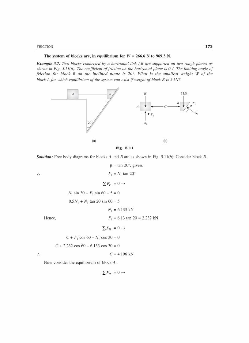
FRICTION 173
The system of blocks are, in equilibrium for W = 266.6 N to 969.3 N.
Example 5.7. Two blocks connected by a horizontal link AB are supported on two rough planes asshown in Fig. 5.11(a). The coefficient of friction on the horizontal plane is 0.4. The limiting angle offriction for block B on the inclined plane is 20°. What is the smallest weight W of theblock A for which equilibrium of the system can exist if weight of block B is 5 kN?
20°
(a) (b)
Fig. 5.11
Solution: Free body diagrams for blocks A and B are as shown in Fig. 5.11(b). Consider block B.
µ = tan 20°, given.
∴ F1 = N1 tan 20°
VF∑ = 0 →
N1 sin 30 + F1 sin 60 – 5 = 0
0.5N1 + N1 tan 20 sin 60 = 5
N1 = 6.133 kN
Hence, F1 = 6.13 tan 20 = 2.232 kN
HF∑ = 0 →
C + F1 cos 60 – N1 cos 30 = 0
C + 2.232 cos 60 – 6.133 cos 30 = 0
∴ C = 4.196 kN
Now consider the equilibrium of block A.
HF∑ = 0 →
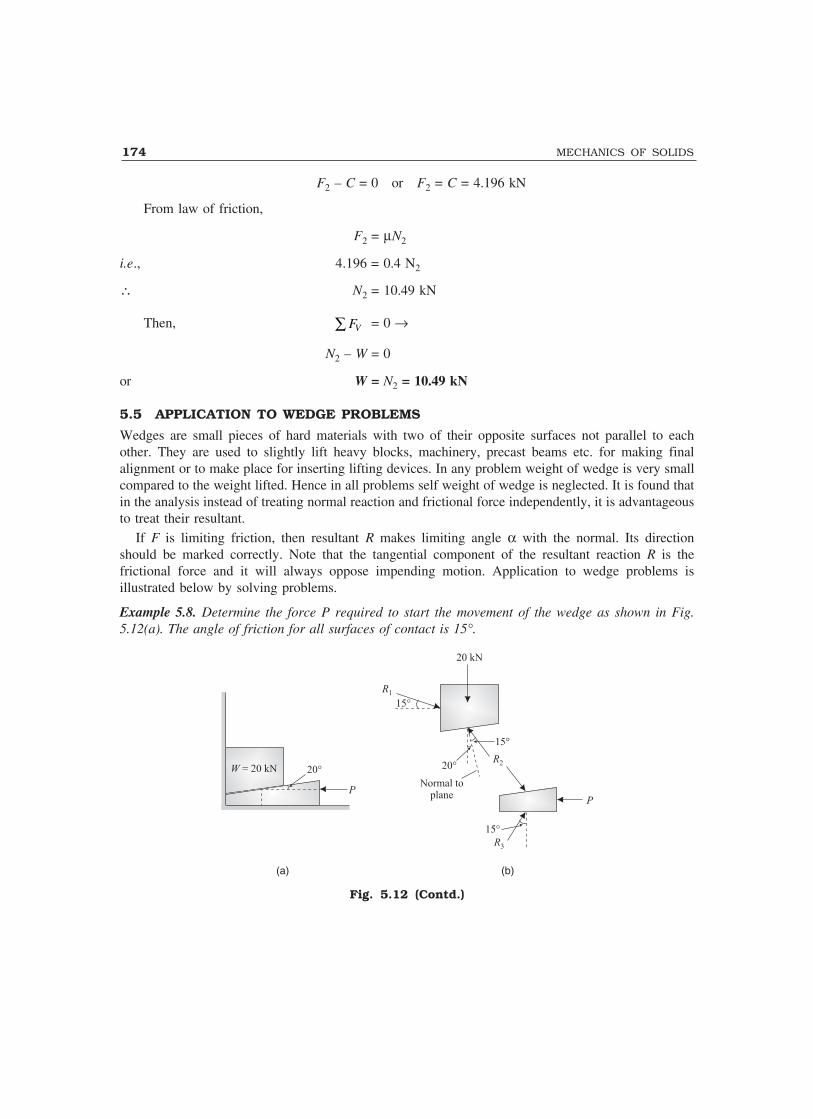
174 MECHANICS OF SOLIDS
F2 – C = 0 or F2 = C = 4.196 kN
From law of friction,
F2 = �N2
i.e., 4.196 = 0.4 N2
∴ N2 = 10.49 kN
Then, VF∑ = 0 →
N2 – W = 0
or W = N2 = 10.49 kN
5.5 APPLICATION TO WEDGE PROBLEMS
Wedges are small pieces of hard materials with two of their opposite surfaces not parallel to eachother. They are used to slightly lift heavy blocks, machinery, precast beams etc. for making finalalignment or to make place for inserting lifting devices. In any problem weight of wedge is very smallcompared to the weight lifted. Hence in all problems self weight of wedge is neglected. It is found thatin the analysis instead of treating normal reaction and frictional force independently, it is advantageousto treat their resultant.
If F is limiting friction, then resultant R makes limiting angle � with the normal. Its directionshould be marked correctly. Note that the tangential component of the resultant reaction R is thefrictional force and it will always oppose impending motion. Application to wedge problems isillustrated below by solving problems.
Example 5.8. Determine the force P required to start the movement of the wedge as shown in Fig.5.12(a). The angle of friction for all surfaces of contact is 15°.
(a) (b)
Fig. 5.12 (Contd.)

FRICTION 175
(c) (d)
Fig. 5.12
Solution: As wedge is driven, it moves towards left and the block moves upwards. When motion isimpending limiting friction develops. Hence resultant force makes limiting angle of 15° with normal.The care is taken to mark 15° inclination such that the tangential component of the resultant opposesthe impending motion.
The free body diagrams of the block and wedge are shown in Fig. 5.12(b). The forces on block andwedge are redrawn in Figs. 5.12(c) and (d) so that Lami’s theorem can be applied conveniently.Applying Lami’s theorem to the system of forces on block
1
sin (180 15 20)
R
− −= 2
sin (90 15)
R
− =
20
sin (15 20 90 15)+ + +
i.e., 1
sin 145
R= 2
sin 75
R =
20
sin 140
∴ R1 = 17.85 kN
and R2 = 30.05 kN
Applying Lami’s theorem to system of forces on the wedge, we get
sin 130
P= 2
sin 105
R
∴ P = 23.84 kN
Example 5.9. A block weighing 160 kN is to be raised by means of the wedges A and B as shown inFig. 5.13(a). Find the value of force P for impending motion of block C upwards, if coefficient offriction is 0.25 for all contact surfaces. The self weight of wedges may be neglected.
Solution: Let φ be the angle of limiting friction.
∴ φ = tan–1 (0.25) = 14.036°
The free body diagrams of wedges A, B and block C are shown in Fig. 5.13(b). The problem beingsymmetric, the reactions R1 and R2 on wedges A and B are equal. The system of forces on block C and

176 MECHANICS OF SOLIDS
on wedge A are shown in the form convenient for applying Lami’s theorem [Ref. Figs. 5.13(c) and(d)].
(a) (b)
(c) (d)
Fig. 5.13
Consider the equilibrium of block C.
1
sin (180 16 )
R
− − φ=
160
sin 2( 16)φ +
i.e., 1
sin 149.96
R=
160
sin 60.072, since φ = 14.036°.
∴ R1 = 92.42 kNConsider the equilibrium of the wedge A. Applying Lami’s theorem, we get
sin (180 16)
P
− φ − φ −= 1
sin (90 )
R
+ φ
∴ P = 92.42 sin 135.928
sin 104.036, since φ = 14.036.
i.e., P = 66.26 kN
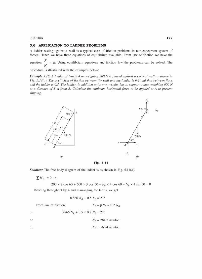
FRICTION 177
5.6 APPLICATION TO LADDER PROBLEMS
A ladder resting against a wall is a typical case of friction problems in non-concurrent system offorces. Hence we have three equations of equilibrium available. From law of friction we have the
equation F
N = µ. Using equilibrium equations and friction law the problems can be solved. The
procedure is illustrated with the examples below:
Example 5.10. A ladder of length 4 m, weighing 200 N is placed against a vertical wall as shown inFig. 5.14(a). The coefficient of friction between the wall and the ladder is 0.2 and that between floorand the ladder is 0.3. The ladder, in addition to its own weight, has to support a man weighing 600 Nat a distance of 3 m from A. Calculate the minimum horizontal force to be applied at A to preventslipping.
4 m
3 m
2 m
600 N
200 N
60°
B
A
(a) (b)
600 NN
B
P
200 N
FB
B
A
NA
FA
60°
P
Fig. 5.14
Solution: The free body diagram of the ladder is as shown in Fig. 5.14(b).
AM∑ = 0 →
200 � 2 cos 60 + 600 � 3 cos 60 – FB � 4 cos 60 – NB � 4 sin 60 = 0
Dividing throughout by 4 and rearranging the terms, we get
0.866 NB + 0.5 FB = 275
From law of friction, FB = �NB = 0.2 NB
∴ 0.866 NB + 0.5 � 0.2 NB = 275
or NB = 284.7 newton.
∴ FB = 56.94 newton.

178 MECHANICS OF SOLIDS
VF∑ = 0 →
NA – 200 – 600 + FB = 0
NA = 743.06 newton, since FB = 56.94
∴ FA = µANA
= 0.3 � 743.06 = 222.9 newton
HF∑ = 0 →
P + FA – NB = 0
∴ P = NB – FA = 284.7 – 222.9
i.e., P = 61.8 newton
Example 5.11. The ladder shown in Fig. 5.15(a) is 6 m long and is supported by a horizontal floorand a vertical wall. The coefficient of friction between the floor and the ladder is 0.25 and between thewall and the ladder is 0.4. The weight of the ladder is 200 N and may be considered as a concentratedload at G. The ladder supports a vertical load of 900 N at C which is at a distance of 1 m from B.Determine the least value of � at which the ladder may be placed without slipping. Determine thereaction at that stage.
G
�
B
A
6 m
3 m
1 m
C
900 NN
B
200 N
FB
B
A
NA
FA
�
G
C
� = 0.4
� = 0.25
(a) (b)
900 N
200 N
Fig. 5.15
Solution: Figure 5.15(b) shows the free body diagram of the ladder.From law of friction,

FRICTION 179
FA = 0.25 NA ...(i)
FB = 0.40 NB ...(ii)
Σ FV = 0 →
NA – 200 – 900 + FB = 0
i.e., NA + 0.4 NB = 900 + 200 = 1100 ...(iii)
FH� = 0 →
FA – NB = 0 i.e., FA = NB
i.e., 0.25 NA = NB ...(iv)
From eqns. (iii) and (iv), we get
NA (1 + 0.4 � 0.25) = 1100
or NA = 1000 newton
∴ FA = 0.25 � NA = 0.25 � 1000 = 250 N
From eqn. (iv) NB = 0.25 NA = 250 N
∴ FB = 0.4 � NB = 0.4 � 250 = 100 N
AM∑ = 0 →
200 � 3 cos α + 900 � 5 cos α – FB � 6 cos α – NB � 6 sin α = 0
∴ Substituting the values of FB and NB, we get
200 � 3 cos α + 900 � 5 cos α – 100 � 6 cos α – 250 � 6 sin α = 0.
or 4500 cos α = 1500 sin α
or tan α = 3
∴ ααααα = 71.57°
Example 5.12. A ladder of length L rests against a wall, the angle of inclination being 45°. If thecoefficient of friction between the ladder and the ground and that between ground and the wall is0.5 each, what will be the maximum distance on ladder to which a man whose weight is 1.5 timesthe weight of ladder may ascend before the ladder begins to slip?
Solution: Figure 5.16(a) shows the ladder when it is about to slip when the man weighing 1.5 Wis at a distance, ‘aL’ from the end A. Its free body diagram is shown in Fig. 5.16(b).
Since ladder is on the verge of slipping, from law of friction,FA = µNB = 0.5 NB ...(1)
and FB = µNB = 0.5 NB ...(2)ΣH = 0 →

180 MECHANICS OF SOLIDS
.
L
05
L
aL
1.5 W
W
B
A
L
0.5L
aL
1.5 W
W
A
BNB
FB
FA
NA
45°
Fig. 5.16
FA – NB = 0 or NB = FA = 0.5 NA ...(3)
∴ FB = 0.5 NB = 0.25 NA ...(4)
ΣV = 0 →NA + FB = W + 1.5 W
i.e., NA + 0.25 NA = 2.5 W
or NA =2.5
1.5W = 1.667 W ...(5)
ΣMA = 0 →–FB L cos 45° – NB L sin 45° + 1.5 W aL cos 45º + W 0.5 L cos 45º = 0
Since sin 45° = cos 45°, we get
FB + NB = 1.5 aW + 0.5 W
0.25 NA + 0.5 NA = 1.5 aW + 0.5 W
i.e., 0.75 × 1.667 W = 1.5 aW + 0.5 W
i.e., 1.25 = 1.5 a + 0.5
or a =0.75
1.5 = 0.5
Thus in this case the man can ascend up to ‘0.5 L’ of ladder.
5.7 BELT FRICTION
The transmission of power by means of belt or rope drives is possible because of friction whichexists between the wheels and the belt. Similarly, band brakes stops the rotating discs because offriction between the belt and the disc. All along the contact surface the frictional resistance develops.Hence, the tension in the rope is more on the side it is pulled and is less on the other side.Accordingly, the two sides of the rope may be called as tight side and slack side.

FRICTION 181
Relationship between Tight Side and Slack Side Forces in a RopeFigure 5.17 (a) shows a load W being pulled by a force P over a fixed drum. Let the force on slackside be T1 and on tight side by T2 [Fig. 5.17(b)]. T2 is more than T1 because frictional force developsbetween drum and the rope [Fig. 5.17(c)]. Let θ be the angle of contact between rope and the drum.Now, consider an elemental length of rope as shown in Fig. 5.17(d). Let T be the force on slack sideand T + dT on tight side. There will be normal reaction N on the rope in the radial direction andfrictional force F = µN in the tangential direction. Then,
WP(a) (b)
θ
T2T1
(c)
T2T1
F
d2θ
TT+ dT N
dθ
(d)
F
Fig. 5.17
Σ Forces in radial direction = 0, gives
N Td
T dTd− − + =sin sin
θ θ2 2
0� �
Since dθ is small, sin d θ2
=d θ2
∴ − − + =N Td
T d Tdθ θ
2 20� � ...(1)
i.e., N = Td T
d+���
���2
θ
From the law of friction,
F N Td T
d= = +���
���
µ µ θ2
...(2)
where µ is coefficient of friction.Now, Σ forces in tangential direction = 0, gives
( )cos cos2 2
d dT dT F T
θ θ+ = +
Since d θ2
is small, cos d θ2
= 1
∴ T + dT = F + T
or dT = F ...(3)
From (2) and (3), dT = µ Td T
d+���
���2
θ
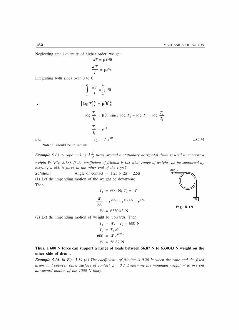
182 MECHANICS OF SOLIDS
Neglecting small quantity of higher order, we get dT = µTdθ
d T
T = µdθ.
Integrating both sides over 0 to θ.
2
1 0
T
T
d Td
T
θ
= µ θ∫ ∫
∴ =log TT
T
1
20µ θ θ
logTT
2
1
= µθ ; since log T2 – log T1 = log T
T2
1
TT
e2
1
= µθ
i.e., T2 = T1eµθ ...(5.4)Note: θ should be in radians.
Example 5.13. A rope making 1 14
turns around a stationary horizontal drum is used to support a
weight W (Fig. 5.18). If the coefficient of friction is 0.3 what range of weight can be supported byexerting a 600 N force at the other end of the rope?
Solution: Angle of contact = 1.25 × 2π = 2.5π(1) Let the impending motion of the weight be downward.
Then,T1 = 600 N; T2 = W
2.5 0.3 2.5 0.75
600W
e e eµ π × π π= = =
W = 6330.43 N
(2) Let the impending motion of weight be upwards. Then
T1 = W; T2 = 600 N
T2 = T1 eµθ
600 = W e0.75π
W = 56.87 N
Thus, a 600 N force can support a range of loads between 56.87 N to 6330.43 N weight on theother side of drum.
Example 5.14. In Fig. 5.19 (a) The coefficient of friction is 0.20 between the rope and the fixeddrum, and between other surface of contact µ = 0.3. Determine the minimum weight W to preventdownward motion of the 1000 N body.
Fig. 5.18
600 N
W
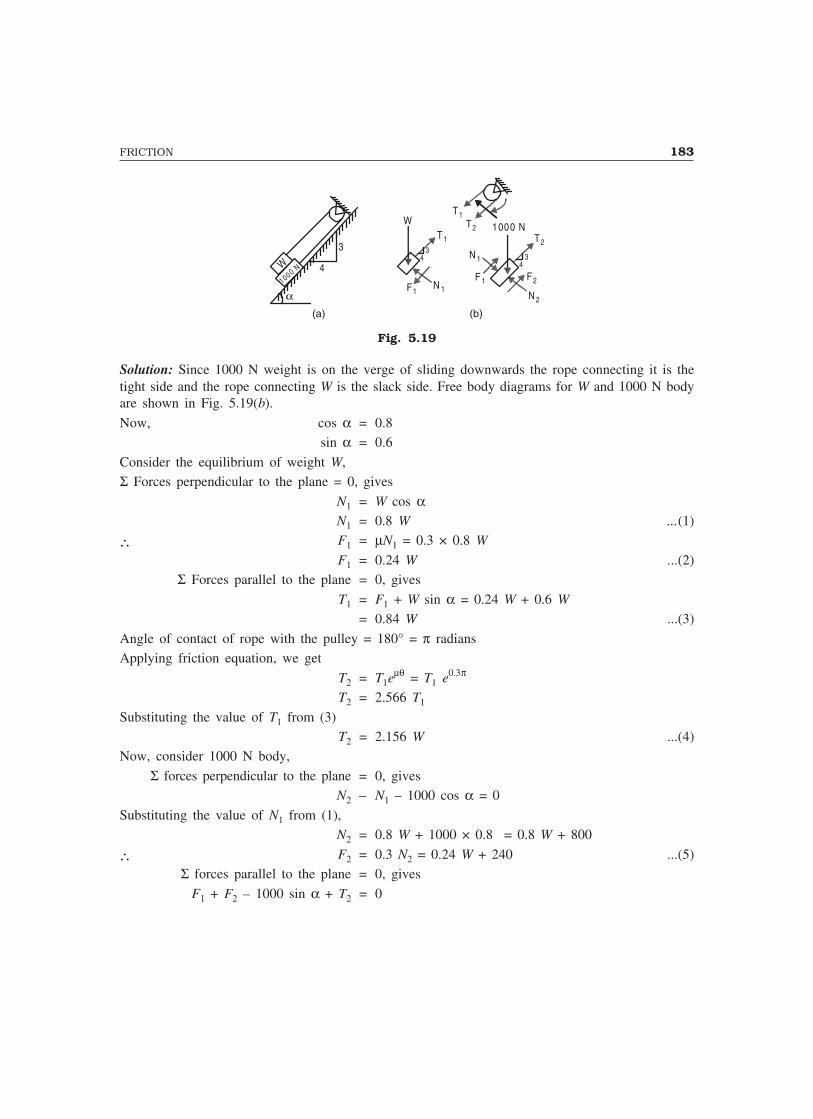
FRICTION 183
W1000 N 4
3 34
F1N 1
T1
W1000 N
T2
34
N 1
F 1 F2
N 2
T1T2
α
(a) (b)
Fig. 5.19
Solution: Since 1000 N weight is on the verge of sliding downwards the rope connecting it is thetight side and the rope connecting W is the slack side. Free body diagrams for W and 1000 N bodyare shown in Fig. 5.19(b).
Now, cos α = 0.8sin α = 0.6
Consider the equilibrium of weight W,Σ Forces perpendicular to the plane = 0, gives
N1 = W cos αN1 = 0.8 W ...(1)
∴ F1 = µN1 = 0.3 × 0.8 W
F1 = 0.24 W ...(2)Σ Forces parallel to the plane = 0, gives
T1 = F1 + W sin α = 0.24 W + 0.6 W
= 0.84 W ...(3)
Angle of contact of rope with the pulley = 180° = π radiansApplying friction equation, we get
T2 = T1eµθ = T1 e0.3π
T2 = 2.566 T1
Substituting the value of T1 from (3)T2 = 2.156 W ...(4)
Now, consider 1000 N body,
Σ forces perpendicular to the plane = 0, givesN2 – N1 – 1000 cos α = 0
Substituting the value of N1 from (1),N2 = 0.8 W + 1000 × 0.8 = 0.8 W + 800
∴ F2 = 0.3 N2 = 0.24 W + 240 ...(5)Σ forces parallel to the plane = 0, gives
F1 + F2 – 1000 sin α + T2 = 0
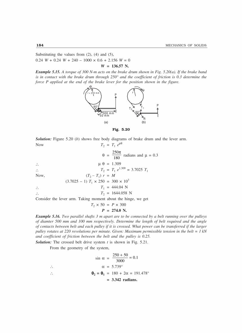
184 MECHANICS OF SOLIDS
Substituting the values from (2), (4) and (5),0.24 W + 0.24 W + 240 – 1000 × 0.6 + 2.156 W = 0
W = 136.57 N.Example 5.15. A torque of 300 N-m acts on the brake drum shown in Fig. 5.20(a). If the brake bandis in contact with the brake drum through 250° and the coefficient of friction is 0.3 determine theforce P applied at the end of the brake lever for the position shown in the figure.
M
r = 2 5 0 m m
300 m m50 m m
P
(a)
M
P
r
90°
R
T2T 1
(b)
90°
Fig. 5.20
Solution: Figure 5.20 (b) shows free body diagrams of brake drum and the lever arm.Now T2 = T1 eµθ
θ =250180
π radians and µ = 0.3
∴ µ θ = 1.309
∴ T2 = T1 e1.309 = 3.7025 T1
Now, (T2 – T1) r = M
(3.7025 – 1) T1 × 250 = 300 × 103
∴ T1 = 444.04 N
∴ T2 = 1644.058 NConsider the lever arm. Taking moment about the hinge, we get
T2 × 50 = P × 300P = 274.0 N.
Example 5.16. Two parallel shafts 3 m apart are to be connected by a belt running over the pulleysof diamter 500 mm and 100 mm respectively. Determine the length of belt required and the angleof contacts between belt and each pulley if it is crossed. What power can be transferred if the largerpulley rotates at 220 revolutions per minute. Given: Maximum permissible tension in the belt = 1 kNand coefficient of friction between the belt and the pulley is 0.25.
Solution: The crossed belt drive system t is shown in Fig. 5.21.From the geometry of the system,
sin α =250 50
0.13000
+ =
∴ α = 5.739°
∴ θθθθθ2 = θθθθθ1 = 180 + 2α = 191.478°
= 3.342 radians.

FRICTION 185
3000D
α
α
θ
C
B
G
αα
α
θ2500 100
E
F
A
Fig. 5.21
Length of belt = Arc length DC + Arc length FE + 2BG
= 250 θ1 + 50 θ2 + 2 × 3000 cos α= 250 × 3.342 + 50 × 3.342 + 2 × 3000 cos 5.734°
= 6972.5 mm.Max. tension in the belt = 1 kN = 1000 N.
From rope friction formula
2
1
T
T= eµθ = e0.25 × 3.342
= e0.6684 = 2.306
In this case T2 = maximum tension = 1000 N
∴ T1 =1000
433.66 N2.306
=
Velocity of the belt = r θ= 250 × 220 × 2π mm/min.
=250 220 2
60
× × π mm/sec.
= 5799.6 mm/sec.∴ Power transmitted = (T2 – T1) × Velocity
= (1000 – 433.66) × 5759.6= 3261884 N-mm/sec.
= 3.261884 kW.Example 5.17. In the above example, if the belt is parallel connected find angle of contact, lengthof belt and minimum that can be transmitted.
Solution: The parallel drive system is as shown in Fig. 5.22.

186 MECHANICS OF SOLIDS
D
α
α
θ1
C
B
G
αα
α
θ2500 100A
E
F
Fig. 5.22
From the geometry of the system
sin α =250 – 50
3000∴ α = 3.822°
∴ θθθθθ1 = π + 2α = 180 + 2 × 3.822
= 187.644°
= 3.275 radians.
θθθθθ2 = π – 2α = 180 – 2 × 3.822
= 172.356
= 3.008 radians.
Length of belt required
= Arc length CD + Arc length EF + 2BG
= 250 θ1 + 50 θ2 + 2 2(3000) (250 50)− −= 250 × 3.275 + 50 × 3.008 + 2 × 2993.325
= 6955.8 mm.
As frictional force is less on smaller pulley, slippage takes place on smaller pulley. Hence
2
1
T
T= eµθ2 = e0.25 × 3.008 = 2.1212
∴ T1 = 2 1000471.4 Newton
2.1212 2.1212
T = =

FRICTION 187
Velocity of belt =2 220 2 220
25060 60
rπ × π ×× = ×
= 5759.6 mm/sec.∴ Maximum power that can be transferred without slippage
= (T2 – T1) × Velocity= (1000 – 471.4) × 5759.6 = 3044517 N mm/sec
= 3.044517 kW.
IMPORTANT FORMULAE
1. µ = Limiting F
N = tan α
2. T2 = T1 eµθ
THEORY QUESTIONS
1. State the laws of dry friction.
2. Explain the terms: coefficient of friction, angle of friction and cone of friction.3. Derive the expression for the relationship between tight side and slack side forces in a belt
friction problem.
PROBLEMS FOR EXERCISE
1. A pull of 180 N applied upward at 30° to a rough horizontal plane was required to just movea body resting on the plane while a push of 220 N applied along the same line of action wasrequired to just move the same body downwards. Determine the weight of the body and thecoefficient of friction. [Ans. W = 990 N; µ = 0.1732]
2. The block A shown in Fig. 5.23 weighs 2000 N. The cord attached to if passes over africtionless pulley and supports a weight equal to 800 N. The value of coefficient frictionbetween A and the horizontal plane is 0.35. Determine the horizontal force P : (i) If the motionis impending towards the left. (ii) if the motion is impending towards the right.
[Ans. (i) 1252.82 N (ii) 132.82 N]
800 N
2000 NP30°
A
Fig. 5.23
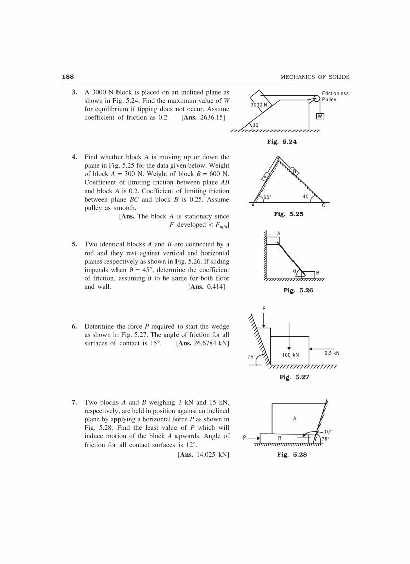
188 MECHANICS OF SOLIDS
Fig. 5.24
AB
60° 40°
A C
A
Bθ
P
100 kN 2.5 kN75°
P B
A
10°75°
3. A 3000 N block is placed on an inclined plane asshown in Fig. 5.24. Find the maximum value of Wfor equilibrium if tipping does not occur. Assumecoefficient of friction as 0.2. [Ans. 2636.15]
4. Find whether block A is moving up or down theplane in Fig. 5.25 for the data given below. Weightof block A = 300 N. Weight of block B = 600 N.Coefficient of limiting friction between plane ABand block A is 0.2. Coefficient of limiting frictionbetween plane BC and block B is 0.25. Assumepulley as smooth.
[Ans. The block A is stationary sinceF developed < Fmin]
5. Two identical blocks A and B are connected by arod and they rest against vertical and horizontalplanes respectively as shown in Fig. 5.26. If slidingimpends when θ = 45°, determine the coefficientof friction, assuming it to be same for both floorand wall. [Ans. 0.414]
6. Determine the force P required to start the wedgeas shown in Fig. 5.27. The angle of friction for allsurfaces of contact is 15°. [Ans. 26.6784 kN]
7. Two blocks A and B weighing 3 kN and 15 kN,respectively, are held in position against an inclinedplane by applying a horizontal force P as shown inFig. 5.28. Find the least value of P which willinduce motion of the block A upwards. Angle offriction for all contact surfaces is 12°.
[Ans. 14.025 kN]
Fig. 5.25
Fig. 5.26
Fig. 5.27
Fig. 5.28
3000 N
W
30°
Fric tionlessPu lley

FRICTION 189
15°
A P
B
P
15°
Pier
W = 20 ,000 N
60°
4 m
2.7
m2
m
200 N
800 N
B
A
5°
5°
A
C
BP
8. In Fig. 5.29, C is a stone block weighing 6 kN. It isbeing raised slightly by means of two wooden wedgesA and B with a force P on wedge B. The anglebetween the contacting surfaces of the wedge is 5°.If coefficient of friction is 0.3 for all contactingsurfaces, compute the value of P required to impendupward motion of the block C. Neglect weight of thewedges. [Ans. 2.344 kN]
9. Find the horizontal force P required to push the blockA of weight 150 N which carries block B of weight1280 N as shown in Fig. 5.30. Take angle of limitingfriction between floor and block A as 14° and thatbetween vertical wall and block B as 13° andcoefficient of limiting friction between the blocks as0.3. [Ans. P = 1294.2 N]
10. The level of precast beam weighing 20,000 N is tobe adjusted by driving a wedge as shown in Fig.5.31. If coefficient of friction between the wedgeand pier is 0.35 and that between beam and the wedgeis 0.25, determine the minimum force P required on
the wedge to make adjustment of the beam. Angle of the wedge is 15°. (Hint: Vertical componentof reaction on wedge at contact with beam = 1/2 vertical load on beam = 10,000 kN)
[Ans. 9057.4 N]
11. A ladder 5 m long rests on a horizontal ground and leans against a smooth vertical wall at anangle of 70° with the horizontal. The weight of the ladder is 300 N. The ladder is on the vergeof sliding when a man weighing 750 N stands on a rung 1.5 m high. Calculate the coefficientof friction between the ladder and the floor.
[Ans. µ = 0.1837]
12. A 4 m ladder weighing 200 N is placed against a vertical wallas shown in Fig. 5.32 as a man weighing 800 N, reaches a point2.7 m from A, the ladder is about to slip. Assuming that thecoefficient of friction between the ladder and the wall is 0.2,determine the coefficient of friction between the ladder and thefloor. [Ans. 0.3548]
13. A uniform ladder of length ‘L’ rests against a vertical wall makingan angle of 60° with the horizontal. Coefficient of friction betweenwall and ladder and ground and ladder are 0.3 and 0.25respectively. A man weighing 650 N ascends the ladder. Howhigh he will be able to go before the ladder slips? Find the magnitude of weight to be put at thebottom of the ladder so as to make it just sufficient to permit the man to go to the top. Takeladder’s weight = 900 N.
(Hint. Find P as found in Example 11. Then W = P
µ)
[Ans. (i) To a length of 0.4345 L i.e., to a height of 0.435 L sin 60° = 0.367 L metres.(ii) W = 777.68 N]
Fig. 5.29
Fig. 5.30
Fig. 5.31
Fig. 5.32
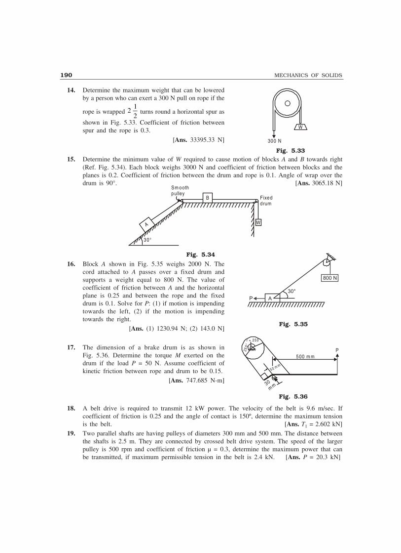
190 MECHANICS OF SOLIDS
14. Determine the maximum weight that can be loweredby a person who can exert a 300 N pull on rope if the
rope is wrapped 212
turns round a horizontal spur as
shown in Fig. 5.33. Coefficient of friction betweenspur and the rope is 0.3.
[Ans. 33395.33 N]
15. Determine the minimum value of W required to cause motion of blocks A and B towards right(Ref. Fig. 5.34). Each block weighs 3000 N and coefficient of friction between blocks and theplanes is 0.2. Coefficient of friction between the drum and rope is 0.1. Angle of wrap over thedrum is 90°. [Ans. 3065.18 N]
A
Fixeddrum
W
30°
Sm oothpulley
B
Fig. 5.34
16. Block A shown in Fig. 5.35 weighs 2000 N. Thecord attached to A passes over a fixed drum andsupports a weight equal to 800 N. The value ofcoefficient of friction between A and the horizontalplane is 0.25 and between the rope and the fixeddrum is 0.1. Solve for P: (1) if motion is impendingtowards the left, (2) if the motion is impendingtowards the right.
[Ans. (1) 1230.94 N; (2) 143.0 N]
17. The dimension of a brake drum is as shown inFig. 5.36. Determine the torque M exerted on thedrum if the load P = 50 N. Assume coefficient ofkinetic friction between rope and drum to be 0.15.
[Ans. 747.685 N-m]
18. A belt drive is required to transmit 12 kW power. The velocity of the belt is 9.6 m/sec. Ifcoefficient of friction is 0.25 and the angle of contact is 150º, determine the maximum tensionis the belt. [Ans. T1 = 2.602 kN]
19. Two parallel shafts are having pulleys of diameters 300 mm and 500 mm. The distance betweenthe shafts is 2.5 m. They are connected by crossed belt drive system. The speed of the largerpulley is 500 rpm and coefficient of friction µ = 0.3, determine the maximum power that canbe transmitted, if maximum permissible tension in the belt is 2.4 kN. [Ans. P = 20.3 kN]
Fig. 5.33
W
300 N
Fig. 5.35
Fig. 5.36
500 m mP
r = 2 5 0
250°
30mm
5 0 m m
800 N
30°
AP
6Simple Machines
A simple machine is a device with the help of which heavy loads are lifted by applying small effectsin a convenient direction. Pulley used to lift water from a well and screw jacks used to lift motorcar are some of the common examples of simple machines. In this chapter some of the termsconnected with simple machines are explained first followed by the description of the characteristicfeatures of levers, systems of pulleys, wheel and axle, Weston differential pulley block, inclinedplane, simple screw jack, differential screw jack and winch crab.
6.1 DEFINITIONS
The terms commonly used while dealing with simple machines are defined below:
Load: This is the resistance to be overcome by the machine.Effort: This is the force required to overcome the resistance to get the work done by the
machine.
Mechanical Advantage: This is the ratio of load lifted to effort applied. Thus, if W is the loadand P is the corresponding effort, then
Mechanical Advantage = W
P...(6.1)
Velocity Ratio: This is the ratio of the distance moved by the effort to the distance movedby the load in the same interval of time. Thus,
Velocity Ratio = D
d...(6.2)
where, D – distance moved by effort
d – distance moved by the load.
Input: The work done by the effort is known as input to the machine. Since work done bya force is defined as the product of the force and the distance moved in the direction of the force,
Input = P × D ...(6.3)
If force P is in newton and distance D is in metre, the unit of input will be N-m. OneN-m work is also known as one Joule (J).
Output: It is defined as useful work got out of the machine, i.e., the work done by the load.Thus,
Output = W × d ...(6.4)
191

192 MECHANICS OF SOLIDS
Efficiency: This is defined as the ratio of output to the input. Thus, if we use notation η forefficiency,
η = Output
Input =
W d
P D
××
= W
P
d
D×
= Mechanical Advantage (MA) × 1
Velocity Ratio ( )VR
= MA
VR...(6.5)
i.e., Efficiency = Mechanical Advantage
Velocity Ratio
Ideal Machine: A machine whose efficiency is 1 (i.e., 100%) is called an ideal machine. Inother words, in an ideal machine, the output is equal to the input. From eqn. (6.5), in an idealmachine,
Velocity Ratio = Mechanical AdvantageIdeal Effort: Ideal effort is the effort required to lift the given load by the machine assuming
the machine to be ideal.For ideal machine,
VR = MA
If Pi is the ideal effort, then
VR = W
Pi
∴ Pi = W
VR...(6.6)
Ideal Load: Ideal load is the load that can be lifted using the given effort by the machine,assuming it to be ideal.
For the ideal machine,VR = MA
If Wi is the ideal load, then
VR = WP
i
∴ Wi = VR × P ...(6.7)
6.2 PRACTICAL MACHINES
In practice, it is difficult to get an ideal machine. Friction exists between all surfaces of contacts ofmovable parts. Some of the work done by the effort is utilised to overcome frictional resistance.Hence, the useful work done in lifting the load is reduced, resulting in reduction of efficiency.
Let P = actual effort required
Pi = ideal effort requiredW = actual load to be lifted
Wi = ideal load to be lifted

SIMPLE MACHINES 193
Then,
P – Pi is called effort lost in friction and W – Wi is called frictional resistance.
Now, η = MA
VR
W
P VR= × 1
From eqn. (6.6), Pi = W
VR
∴ η = P
Pi
Similarly from eqn. (6.7), Wi = VR × P
∴ η = W
Wi
Thus, η = P
P
W
Wi
i
= ...(6.8)
Example 6.1. In a lifting machine, an effort of 500 N is to be moved by a distance of20 m to raise a load of 10,000 N by a distance of 0.8 m. Determine the velocity ratio, mechanicaladvantage and efficiency of the machine. Determine also ideal effort, effort lost in friction, ideal loadand frictional resistance.
Solution: Load, W = 10,000 N
Effort P = 500 NDistance moved by the effort D = 20 m
Distance moved by the load d = 0.8 m
Mechanical advantage, MA = W
P= 10 000
500
,
= 20
Velocity ratio, VR = D
d= 20
0 8.
= 25
Efficiency, η = MA
VR= 20
25
= 0.8 = 80 per cent
Ideal effort, Pi = W
VR= 10 000
25
, = 400 N
Effort lost in friction = P – Pi
= 500 – 400= 100 N
Ideal load, Wi = P × VR = 500 × 25= 12,500 N

194 MECHANICS OF SOLIDS
Frictional resistance = Wi – W
= 12,500 – 10,000
= 2500 N
6.3 LAW OF MACHINE
The relationship between the load lifted and the effort required in a machine is called the law ofmachine. This is found by conducting experiments in which efforts required for lifting differentloads are determined and then load versus effort graph as shown in Fig. 6.1 is plotted. This isgenerally a straight line which does not pass through the origin.
For actua l m achine
F
B
Cθ
θ
m1
A
O
E For ideal m ach ine
D Load (W )
Effo
rt (
P)
Fig. 6.1
The law of machine can be expressed mathematically in the form:
P = mW + C ...(6.9)where, C is the intercept OA and m = tan θ, the slope of AB. For the ideal machine
MA = VR
W
P = VR
This is a straight line relationship passing through the origin and is shown by line OC inFig. 6.1.
After plotting the law for the actual machine (AB) and the law for ideal machine (OC), it iseasy to determine efficiency at any given load. The vertical line DEF corresponding to given loadOD is drawn. Then,
DE = Pi, effort required in ideal machineDF = P, effort required in actual machine
∴ Friction loss = P – Pi
= DF – DE
= EF
Efficiency, η = P
Pi
= DE
DF
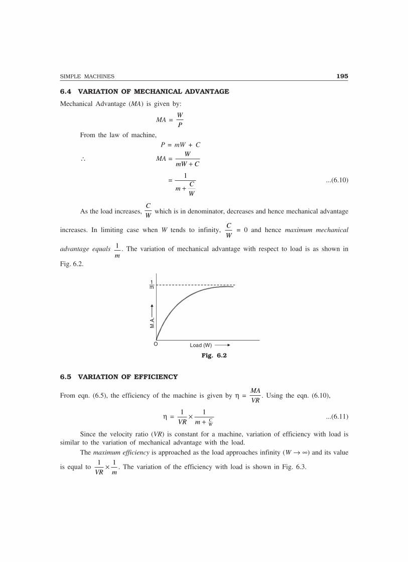
SIMPLE MACHINES 195
6.4 VARIATION OF MECHANICAL ADVANTAGE
Mechanical Advantage (MA) is given by:
MA = W
P
From the law of machine, P = mW + C
∴ MA = W
mW C+
= 1
mC
W+
...(6.10)
As the load increases, C
W which is in denominator, decreases and hence mechanical advantage
increases. In limiting case when W tends to infinity, C
W = 0 and hence maximum mechanical
advantage equals 1
m. The variation of mechanical advantage with respect to load is as shown in
Fig. 6.2.
Load (W)O
M.A
.
1m
Fig. 6.2
6.5 VARIATION OF EFFICIENCY
From eqn. (6.5), the efficiency of the machine is given by η = MA
VR. Using the eqn. (6.10),
η = 1 1
VR m CW
×+
...(6.11)
Since the velocity ratio (VR) is constant for a machine, variation of efficiency with load issimilar to the variation of mechanical advantage with the load.
The maximum efficiency is approached as the load approaches infinity (W → ∞) and its value
is equal to 1 1
VR m× . The variation of the efficiency with load is shown in Fig. 6.3.
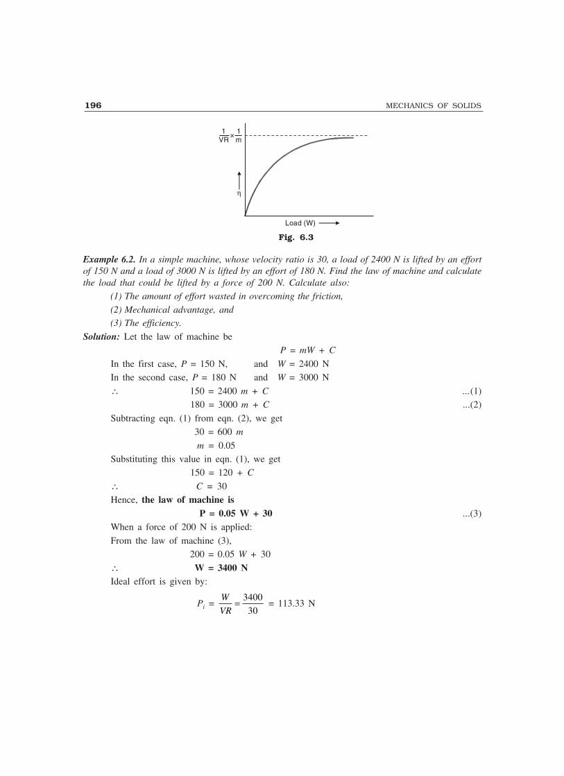
196 MECHANICS OF SOLIDS
Load (W)
η
1VR
1m
×
Fig. 6.3
Example 6.2. In a simple machine, whose velocity ratio is 30, a load of 2400 N is lifted by an effortof 150 N and a load of 3000 N is lifted by an effort of 180 N. Find the law of machine and calculatethe load that could be lifted by a force of 200 N. Calculate also:
(1) The amount of effort wasted in overcoming the friction,
(2) Mechanical advantage, and(3) The efficiency.
Solution: Let the law of machine beP = mW + C
In the first case, P = 150 N, and W = 2400 NIn the second case, P = 180 N and W = 3000 N
∴ 150 = 2400 m + C ...(1)180 = 3000 m + C ...(2)
Subtracting eqn. (1) from eqn. (2), we get30 = 600 m
m = 0.05Substituting this value in eqn. (1), we get
150 = 120 + C
∴ C = 30Hence, the law of machine is
P = 0.05 W + 30 ...(3)When a force of 200 N is applied:
From the law of machine (3),200 = 0.05 W + 30
∴ W = 3400 NIdeal effort is given by:
Pi = W
VR= 3400
30 = 113.33 N
SIMPLE MACHINES 197
∴ Effort wasted in overcoming the friction= P – Pi = 200 – 113.33= 86.67 N
Mechanical advantage = W
P= 3400
200
= 17
Efficiency = MA
VR= 17
30 = .5667
= 56.67%Example 6.3. In a lifting machine an effort of 150 N raised a load of 7700 N. What is the mechanicaladvantage? Find the velocity ratio if the efficiency at this load is 60%. If by the same machine, aload of 13,200 N is raised by an effort of 250 N, what is the efficiency? Calculate the maximummechanical advantage and the maximum efficiency.
Solution: Effort, P = 150 NLoad, W = 7700 N
∴ Mechanical advantage:
MA = W
P= 7700
150 = 51.33
If the efficiency is 60%,
η = 0.6
η = MA
VR
∴ 0.6 = 51 33.
VR
or VR = 51 33
0 6
.
.i.e., VR = 85.55
When an effort of 250 N raised a load of 13,200 N,
MA = W
P= 13 200
250
, = 52.8
∴ η = MA
VR= 52 8
85 55
.
.= 0.6172
i.e., η = 61.72%Let the law of machine be
P = mW + C
In the first case, 150 = 7700 m + C ...(1)In the second case, 250 = 13,200 m + C ...(2)
Subtracting eqn. (1) from eqn. (2), we get100 = 5500 m

198 MECHANICS OF SOLIDS
∴ m = 0.01818∴ Maximum mechanical advantage
= 1 1
0 01818m=
.= 55
Maximum efficiency = 1 1
m VR× =
1
0 01818
1
85 55. .×
= 0.6429= 64.29%
Example 6.4. The efforts required for lifting various loads by a lifting machine are tabulated below:
Load lifted in N 100 200 300 400 500 600
Effort required in N 16.0 22.5 28.0 34.0 40.5 46.5
Determine the law of machine. If the velocity ratio is 25, calculate efficiency at each load and plotefficiency versus load curve. From this curve, determine the maximum efficiency.
Solution: Figure 6.4 shows the graph of effort versus load. From this figure, C = 10 N and slope
m = 30
500 = 0.06
∴ The law of machine is
P = 0.06 W + 10
50
40
30
20
10
0 100 200 300 400 500 600Load (W )
C
0
Effo
rt (
P)
W = 500
P = 30
Fig. 6.4
η = MA
VR
W
P VR
W
P= × = ×1 1
25 =
W
P25
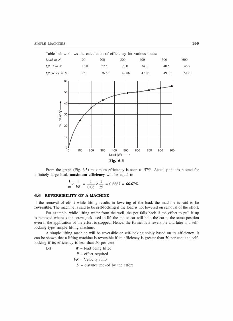
SIMPLE MACHINES 199
Table below shows the calculation of efficiency for various loads:
Load in N 100 200 300 400 500 600
Effort in N 16.0 22.5 28.0 34.0 40.5 46.5
Efficiency in % 25 36.56 42.86 47.06 49.38 51.61
60
50
40
30
20
10
00 100 200 300 400 500 600
Load (W)
% E
ffici
ency
700 800 900
Fig. 6.5
From the graph (Fig. 6.5) maximum efficiency is seen as 57%. Actually if it is plotted forinfinitely large load, maximum efficiency will be equal to
1 1
m VR× =
1
0 06
1
25.× = 0.6667 = 66.67%
6.6 REVERSIBILITY OF A MACHINE
If the removal of effort while lifting results in lowering of the load, the machine is said to bereversible. The machine is said to be self-locking if the load is not lowered on removal of the effort.
For example, while lifting water from the well, the pot falls back if the effort to pull it upis removed whereas the screw jack used to lift the motor car will hold the car at the same positioneven if the application of the effort is stopped. Hence, the former is a reversible and later is a self-locking type simple lifting machine.
A simple lifting machine will be reversible or self-locking solely based on its efficiency. Itcan be shown that a lifting machine is reversible if its efficiency is greater than 50 per cent and self-locking if its efficiency is less than 50 per cent.
Let W – load being liftedP – effort required
VR – Velocity ratioD – distance moved by the effort
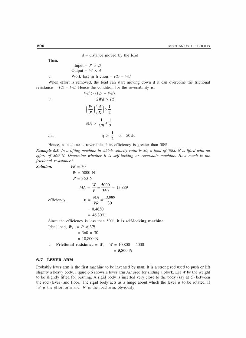
200 MECHANICS OF SOLIDS
d – distance moved by the loadThen,
Input = P × DOutput = W × d
∴ Work lost in friction = PD – Wd
When effort is removed, the load can start moving down if it can overcome the frictionalresistance = PD – Wd. Hence the condition for the reversibility is:
Wd > (PD – Wd)
∴ 2Wd > PD
W
P
d
D��������
> 1
2
MA × 1 1
2VR>
i.e., η > 1
2or 50%.
Hence, a machine is reversible if its efficiency is greater than 50%.Example 6.5. In a lifting machine in which velocity ratio is 30, a load of 5000 N is lifted with aneffort of 360 N. Determine whether it is self-locking or reversible machine. How much is thefrictional resistance?
Solution: VR = 30
W = 5000 N P = 360 N
MA = W
P= 5000
360 = 13.889
efficiency, η = MA
VR= 13 889
30
.
= 0.4630= 46.30%
Since the efficiency is less than 50%, it is self-locking machine.Ideal load, Wi = P × VR
= 360 × 30
= 10,800 N∴ Frictional resistance = Wi – W = 10,800 – 5000
= 5,800 N
6.7 LEVER ARM
Probably lever arm is the first machine to be invented by man. It is a strong rod used to push or liftslightly a heavy body. Figure 6.6 shows a lever arm AB used for sliding a block. Let W be the weightto be slightly lifted for pushing. A rigid body is inserted very close to the body (say at C) betweenthe rod (lever) and floor. The rigid body acts as a hinge about which the lever is to be rotated. If‘a’ is the effort arm and ‘b’ is the load arm, obviously.
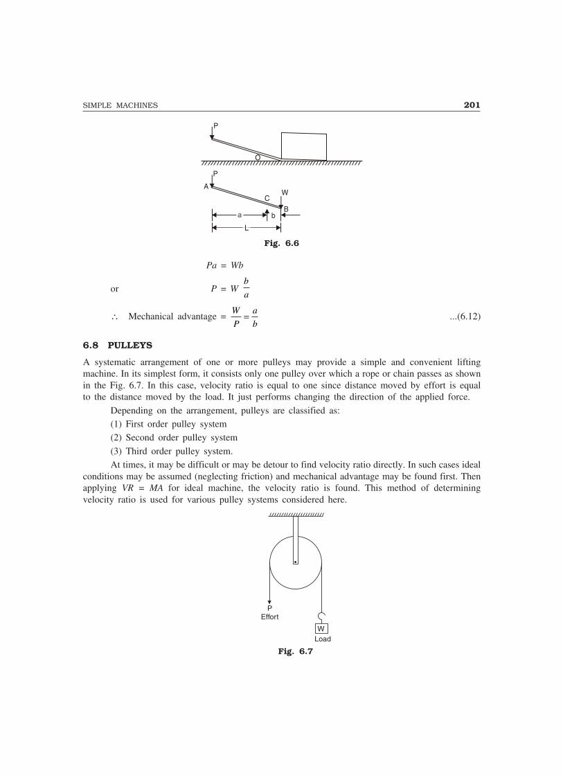
SIMPLE MACHINES 201
P
CW
Bb
O
A
P
Fig. 6.6
Pa = Wb
or P = W b
a
∴ Mechanical advantage = W
P
a
b= ...(6.12)
6.8 PULLEYS
A systematic arrangement of one or more pulleys may provide a simple and convenient liftingmachine. In its simplest form, it consists only one pulley over which a rope or chain passes as shownin the Fig. 6.7. In this case, velocity ratio is equal to one since distance moved by effort is equalto the distance moved by the load. It just performs changing the direction of the applied force.
Depending on the arrangement, pulleys are classified as:(1) First order pulley system(2) Second order pulley system
(3) Third order pulley system.At times, it may be difficult or may be detour to find velocity ratio directly. In such cases ideal
conditions may be assumed (neglecting friction) and mechanical advantage may be found first. Thenapplying VR = MA for ideal machine, the velocity ratio is found. This method of determiningvelocity ratio is used for various pulley systems considered here.
PEffort
WLoad
Fig. 6.7

202 MECHANICS OF SOLIDS
First Order Pulley System
A first order pulley system is shown in the Fig. 6.8. Pulley No. 1 is fixed in position to a supportat top. A rope passes over this pulley and one end of this rope is tied to the support at the top, makinga loop, in which pulley No. 2 is suspended and effort is applied at the other end. One end of anotherrope is tied to pulley No. 2 and the other end to the top support which makes a loop in which pulleyNo. 3 is suspended. Similarly, a number of pulleys can be arranged as shown, when an effort isapplied to lift the load except first pulley all other pulleys move vertically. Therefore, first pulley istermed as fixed pulley and the others as movable pulleys.
Let an effort P be applied to lift a load W. In an ideal pulley system (friction = 0), the rope
which passes over pulley No. 4 is subjected to a tension W
2. Then tension in rope which passes over
pulley No. 3 is W
4 and tension in the rope which passes over pulley No. 2 is W
8. Hence, an effort
equal to W
8 is required to lift a load W.
∴ P = W
8and hence MA =
W
P =
WW
8
= 8 = 23
But in an ideal machine, VR = MA ∴ VR = 23
W8
W8
W8
W4
W4
W4
W2
W2
W2
4
3
2
1
W Load
W8
Effort
Fig. 6.8
It is to be noted that in the system considered, there are three movable pulleys and the velocityratio is 23. If there are only two movable pulleys, then velocity ratio would be 4 (i.e., 22). In general,in the first order pulley system, velocity ratio (VR) is given by 2n, where, n is the number of movablepulleys present in the system. Thus, in first order pulley system
VR = 2n ...(6.13)

SIMPLE MACHINES 203
PEffort
1 1
W
Load
Fig. 6.9
Second Order Pulley System
Figure 6.9 shows a second order pulley system. This system consists of a top pulley block and abottom pulley block. In a pulley block pulleys may be arranged side by side or may be one belowthe other as shown in Fig. 6.9. The top pulley block is fixed in position to the top support whereasbottom pulley block can move vertically along with the load which is attached to it. One end of therope is attached to the hook provided at the bottom of the top pulley block and the effort is appliedat the other end. A single rope goes round all the pulleys. Let an effort P be applied to lift a load W.
Neglecting frictional losses, the tension in the rope all along the length is P. Take the sectionalong (1)–(1) and consider the equilibrium of the bottom pulley block.
The load W is lifted using six ropes having equal tension P
∴ W = 6P, ∴ P = W
6, ∴ MA =
W
P =
WW
6
= 6.
But VR = MA in ideal condition
∴ VR = 6.In general, in the second order pulley system velocity ratio is equal to twice the number of
movable pulleys in the system.
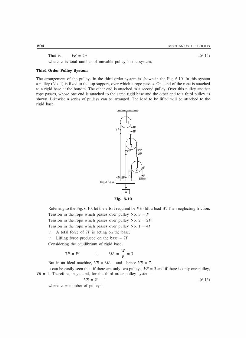
204 MECHANICS OF SOLIDS
That is, VR = 2n ...(6.14)
where, n is total number of movable pulley in the system.
Third Order Pulley System
The arrangement of the pulleys in the third order system is shown in the Fig. 6.10. In this systema pulley (No. 1) is fixed to the top support, over which a rope passes. One end of the rope is attachedto a rigid base at the bottom. The other end is attached to a second pulley. Over this pulley anotherrope passes, whose one end is attached to the same rigid base and the other end to a third pulley asshown. Likewise a series of pulleys can be arranged. The load to be lifted will be attached to therigid base.
1
4P4P4P
2
2P 2P2P
3 P
PP
P4P 2P EffortRigid base
W
Fig. 6.10
Referring to the Fig. 6.10, let the effort required be P to lift a load W. Then neglecting friction,Tension in the rope which passes over pulley No. 3 = P
Tension in the rope which passes over pulley No. 2 = 2P
Tension in the rope which passes over pulley No. 1 = 4P
∴ A total force of 7P is acting on the base.∴ Lifting force produced on the base = 7P
Considering the equilibrium of rigid base,
7P = W ∴ MA = W
P = 7
But in an ideal machine, VR = MA, and hence VR = 7.
It can be easily seen that, if there are only two pulleys, VR = 3 and if there is only one pulley,VR = 1. Therefore, in general, for the third order pulley system:
VR = 2n – 1 ...(6.15)where, n = number of pulleys.

SIMPLE MACHINES 205
6.9 WHEEL AND AXLE
This machine consists of an axle A having diameter d and a wheel B having diameter D (D > d)co-axially fitted as shown in Fig. 6.11. The whole assembly is mounted on ball bearing so that wheeland axle can be rotated.
BA
Effort
WLoad P
Effort
dd
DD
WLoad
(a)
(b)
P
Fig. 6.11
One end of a rope is tied to the pin provided on the wheel and the rope is wound around thewheel. The other end of the rope provides the means for the application of the effort. One end ofanother rope is tied to the pin provided on the axle and wound around the axle in the oppositedirection to that of rope wound to the wheel. To the other end of this rope the load is attached. Ifthe whole assembly is rotated, one rope gets wound up and the other gets unwound.
Suppose the assembly is moved by one complete revolution, then the distance moved by theeffort = π D and distance moved by the load = π d
∴ VR = distance moved by effort
distance moved by load
= ππD
d,
or VR = D
d...(6.16)
6.10 WHEEL AND DIFFERENTIAL AXLE
An improvement over wheel and axle machine is made by using one more wheel of bigger diameterand it is called wheel and differential axle.
d 1
PEffort
W
Load
Fig. 6.12

206 MECHANICS OF SOLIDS
This consists of a differential axle of diameter d1 and d2 (d1 < d2) and a wheel of diameterD, fixed uniaxially as shown in Fig. 6.12. One end of the rope is tied to the pin provided on the axleportion having diameter d1 and a part of the rope is wound around it. The other end of the rope iswound around axle on the portion having diameter d2 in the opposite direction. This pattern ofwinding forms a loop and a simple pulley is installed in this loop as shown in the figure. The loadis attached to this pulley. The second rope is wound to the wheel in such a direction that if it isunwound, the rope around the bigger diameter axle gets wound up and the rope around smallerdiameter axle gets unwound. One end of this second rope provides means for application of theeffort.
Suppose the whole system makes one complete revolution due to the applied effort, then
Total distance moved by the effort at the differential axle = πD
Length of winding of the rope = πd2
Length of unwinding of rope = πd1
∴ Net wound length = πd2 – πd1
= π(d2 – d1)But, the rope is continuous and the load is to be lifted by the pulley block in the loop.
∴ Total height over which pulley is lifted = π( )d d2 1
2
−
and hence the distance moved by the load = π( )d d2 1
2
−
∴ VR = π
πD
d d( )2 1
2−
VR = 2
2 1
D
d d−Hence, velocity ratio in wheel and differential axle is given by:
VR = 2
2 1
D
d d−...(6.17)
6.11 WESTON DIFFERENTIAL PULLEY BLOCK
This is a special type of simple pulley system. It is shown in the Fig. 6.13.
WLoad
Fig. 6.13

SIMPLE MACHINES 207
This system consists of two pulley blocks, one at the top attached to the support and the otherat the bottom hanging in the chain loop. The top block consists of two wheels of different diameters,but fixed co-axially. The bottom block is a simple pulley to which the load W is attached. An endlesschain is wound around the pulley system as shown in the figure. All the wheels are made with teethso as to accommodate the links of the chain. The chain is essentially used to avoid slipping.
To determine velocity ratio of the system, let us consider pulley block as an ideal machineand determine its mechanical advantage first. In ideal machine VR = MA. Let the diameter of thelarger wheel of the top block be D and the diameter of the smaller wheel of the top block be d [Fig.6.14(a)]. Let the effort required to lift the load W be P.
DDdd
W2
W2
W2
W2
W
DDdd
P
W2
W2
(a)
(b)
Fig. 6.14
Then the tension in the chain loop in which pulley is hanging is W
2.
Now, taking moment about the axis of top block [Fig. 6.14(b)],
W D W d
2 2 2 2× = × + P ×
D
2
∴W
4(D – d) =
PD
2
W
P
D
D d=
−2
( )
i.e., MA = 2D
D d( )−
In an ideal machine,
VR = MA = 2D
D d( )−...(6.18)

208 MECHANICS OF SOLIDS
6.12 INCLINED PLANE
Inclined plane is a very simple lifting device. The lift is essentially accomplished with the horizontaldisplacement.
An inclined plane consists of a plane surface at a definite angle over which the load is to belifted.
PEffort W
θ
Fig. 6.15
Figure 6.15 shows a typical inclined plane. Here the load is a roller which is to be lifted toa higher elevation. One end of a rope is tied to the roller and the rope is passed over a pulley attachedat the top of the inclined plane. At the other end of the rope the effort is applied.
Let the angle of inclination of the plane be θ and the length of the inclined plane be L. Then,if the roller is made to roll from bottom to top, applying an effort P, the load is lifted through a heightof L sin θ. In this process the effort P moves through a distance L vertically downwards.
∴ VR = distance moved by the effort
distance through which load is lifted
= L
L sin sinθ θ= 1
∴ VR = 1
sin θ...(6.19)
Example 6.6. In a first order system of pulleys there are three movable pulleys. What is the effortrequired to raise a load of 6000 N ? Assume efficiency of the system to be 80%.
If the same load is to be raised using 520 N, find the number of movable pulleys that arenecessary.
Assume a reduction of efficiency of 5% for each additional pulley used in the system.
Solution: VR = 2n, where n is the number of movable pulleys.VR = 23 = 8
Now, MA = η × VR
= 0.8 × 8
= 6.4
i.e.,W
P = 6.4
∴ P = W
6 4. =
6000
6 4.

SIMPLE MACHINES 209
i.e., P = 937.5 N
In the second case,
Effort = 520 N
Efficiency η = 0.80 – n1 × 0.05
where n1 = number of additional pulleys required and equal to (n – 3).
MA = η × VR
i.e.,W
P = η × VR
∴ W = P × η × 2n
= P(0.8 – n1 × 0.05) × 2n
= P[0.8 – (n – 3) × 0.05] 2n
By going for a trial and error solution, starting with one additional pulley i.e., totally with fourpulleys,
W = 520 [0.8 – (4 – 3) × 0.05] 24 = 6240 N
i.e., if four pulleys are used, a load of 6240 N can be raised with the help of 520 N effort.
∴ Number of movable pulleys required = 4
Example 6.7. What force is required to raise the load W shown in Fig. 6.16 ? Assume efficiency ofthe system to be 85%.
Solution: The pulley system shown in the Fig. 6.16 is a variation of the second order pulley system.
P
W = 12000 N
Fig. 6.16
VR = 2 × number of movable pulleys = 6
MA = η × VR
= 0.85 × 6 = 5.1
i.e.,W
P = 5.1
∴ P = W
51
12 000
51.
,
.= = 2352.94 N

210 MECHANICS OF SOLIDS
Example 6.8. Find the pull required to lift the load W shown in Fig. 6.17(a) assuming the efficiencyof the system to be 78%.
P
W = 12,000 N
P
P
P
(a) (b) (c)
Fig. 6.17
Solution: The pulley system shown in Fig. 6.17(a) is a combination of a first order system and asecond order system as shown in Figs. 6.17(b) and (c).
Let load W be lifted by a distance x. Consider the first order system portion [Fig. 6.17(b)].Here there are two movable pulleys. Hence
VR = 22 = 4In this portion P moves by 4x.
Now, consider the second order pulley system portion [Fig. 6.17(c)]. Here there are twomovable pulleys. Hence VR = 2 × 2 = 4.
∴ Distance moved by the effort in this system = 4x.Hence, the total distance moved by the effort in the given system = 4x + 4x = 8x
∴ VR = 8x
x = 8
Now, MA = η × VR = 0.78 × 8= 6.24
i.e.,WP
= 6.24
∴ P = 12 000
6 24
,
. = 1923.08 N
Example 6.9. A lifting machine consists of pulleys arranged in the third order system. There arethree pulleys in the system. A load of 1000 N is lifted by an effort of 180 N. Find the efficiency ofthe machine and the effort lost in friction.
Solution: For the third order system of pulleys,
VR = 2n – 1where, n is the number of pulleys in the system.
VR = 23 – 1 = 7

SIMPLE MACHINES 211
Now, MA = η × VR
i.e.,W
P = η × VR
∴ η = W
P VR× 1
= 1000
180
1
7× = 0.7937
i.e., η = 79.37%Now,
Ideal effort, Pi = W
VR
= 1000
7
= 142.86 N
∴ Effort lost in friction = P – Pi
= 180 – 142.86= 37.14 N
Example 6.10. What force P is required to raise a load of 2500 N in the system of pulleys shownin Fig. 6.18(a). Assume efficiency of the system to be equal to 70%.
Solution: Figure 6.18(a) can be split into two simple systems as shown in Figs. 6.18(b) and 6.18(c).What is shown in Fig. 6.18(b) is a third order pulley system having two pulleys.
∴ VR = 2n – 1= 22 – 1 = 3
W
PW
(a)
(b)
(c)
P
Fig. 6.18
Figure 6.18(c) is also a third order system, having two pulleys.

212 MECHANICS OF SOLIDS
∴ VR = 22 – 1 = 3
∴ VR of the whole system = 3 + 3 = 6
Now, MA = η × VR
i.e.,W
P = η × VR
∴ P = W
VRη ×
= 2500
0 7 6. ×
i.e., P = 595.24 N
Example 6.11. In a wheel and axle, diameter of the wheel is 500 mm and that of the axle is 200 mm.The thickness of the cord on the wheel is 6 mm and that of the axle is 20 mm. Find the velocity ratioof the machine. If the efficiency when lifting a load of 1200 N with a velocity of 10 metres per minuteis 70%, find the effort necessary.
Solution: Effective wheel diameter = 6
2 + 500 +
6
2
= 506 mm
Effective axle diameter = 20
2 + 200 +
20
2
= 220 mm.
For a wheel and axle, the velocity ratio is given by D
d
∴ VR = 506
220 = 2.30
Mechanical advantage = Efficiency × velocity ratio
= 0.7 × 2.30 = 1.61
MA = W
P
∴ P = 1200
1 61.
i.e., P = 745.34 N
Example 6.12. A load of 20 kN is to be lifted by a differential wheel and axle. It consists ofdifferential axle of 250 mm and 300 mm diameter and the wheel diameter is 800 mm. Find the effortrequired if the efficiency of the machine is 55%.
SIMPLE MACHINES 213
Solution: Differential axle diameters,
d1 = 250 mm and
d2 = 300 mm
Wheel diameter, D = 800 mm
Load, W = 20 kN
Efficiency, η = 55%
Velocity ratio, VR = 2
2 1
D
d d− =
2 800
300 250
×−
= 32
Mechanical advantage
MA = Efficiency × velocity ratio= 0.55 × 32 = 17.6
MA = W
P
∴ P = 20 000
17 6
,
.
i.e., P = 1136.4 N
Example 6.13. A Weston differential pulley block of diameter 500 mm and 200 mm is used to lifta load of 5000 N. Find the effort required if the efficiency is 60%.
Solution: Diameter of pulley block D = 500 mm, and
d = 200 mm
Load, W = 5000 N
Efficiency, η = 60%
Velocity ratio = 2D
D d−
= 2 500
500 200
×−
= 3.33
Mechanical advantage = Efficiency × Velocity ratio
= 0.6 × 3.33 = 2
Effort required, P = W
MA =
5000
2
i.e., P = 2500 N
6.13 SCREW JACK
This is a device commonly used to lift heavy loads. Screw jack works on the principle same as thatof inclined plane. A typical section of the screw jack is shown in the Fig. 6.19.

214 MECHANICS OF SOLIDS
Lever
WScrewhead
Nut
dStand
Fig. 6.19
The device consists of a nut and a screw. Monolithically cast nut and stand form the body ofthe jack. The load is carried by the screw head fitted onto the screw as shown in the figure. The body(consisting of nut) is fixed and the screw is rotated by means of a lever.
The axial distance moved by the nut (or by the screw, relative to each other) when it makesone complete revolution is known as lead of the screw head. The distance between consecutivethreads is called pitch (of a screw thread). If the screw is single threaded, then lead of the screw isequal to the pitch. If the screw is double threaded then lead of the screw is twice the pitch.
Let R be the length of the lever and d be the mean diameter of the screw.Let a load W be lifted using an effort P.
If an effort P is applied at the lever end, it is equivalent to an effort P1 at the screw [Fig. 6.20(a)]and P1 is given by the condition:
P
R 1
P 1
Fig. 6.20(a)
P × R = P1 × d
2
∴ P1 = 2PR
d
Now, consider one complete revolution of the lever. The load W is lifted up by a distance pequal to the lead of the screw.
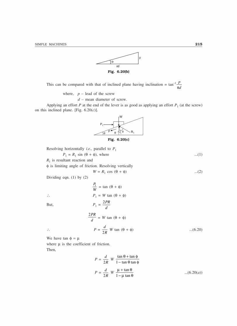
SIMPLE MACHINES 215
θπd
p
Fig. 6.20(b)
This can be compared with that of inclined plane having inclination = tan–1 p
dπwhere, p – lead of the screw
d – mean diameter of screw.Applying an effort P at the end of the lever is as good as applying an effort P1 (at the screw)
on this inclined plane. [Fig. 6.20(c)].
W
P1
Fθ φ R1θ
Fig. 6.20(c)
Resolving horizontally i.e., parallel to P1
P1 = R1 sin (θ + φ), where ...(1)R1 is resultant reaction and
φ is limiting angle of friction. Resolving verticallyW = R1 cos (θ + φ) ...(2)
Dividing eqn. (1) by (2)
P
W1 = tan (θ + φ)
∴ P1 = W tan (θ + φ)
But, P1 = 2PR
d
2PR
d = W tan (θ + φ)
∴ P = d
R2 W tan (θ + φ) ...(6.20)
We have tan φ = µwhere µ is the coefficient of friction.Then,
P = d
R2 W
tan tan
tan tan
θ φθ φ
+−1
P = d
R2 W
µ θµ θ
+−
tan
tan1...(6.20(a))

216 MECHANICS OF SOLIDS
where, tan θ = p
dπIf the load is descending, then the friction will be acting in the reverse direction so that the
resultant reaction R shifts as shown in Fig. 6.20(d).
W
P 1
θφ
θR 1
F
Fig. 6.20(d)
Then eqn. 6.20 changes to
P = d
R2W tan (θ – φ) ...(6.20(b))
Torque required, = T = PR
= d
2W tan (θ + φ)
Hence torque required while ascending
T = d
2 W tan (θ + φ) ...(6.21)
and torque required while descending
T = d
2 W tan (θ − φ) ...(6.21(a))
Now,
VR = Distance moved by the effort
Distance moved by the load
= 2πR
p....(6.22)
Example 6.14. A screw jack raises a load of 40 kN. The screw is square threaded having threethreads per 20 mm length and 40 mm in diameter. Calculate the force required at the end of a lever400 mm long measured from the axis of the screw, if the coefficient of friction between screw andnut is 0.12.
Solution: Screw diameter, d = 40 mm
Lead of the screw, p = 20
3 = 6.667 mm
Load, W = 40 kNLever length, R = 400 mm
µ = 0.12

SIMPLE MACHINES 217
We have
P = d
R2 W
µ θµ θ
+−
tan
tan1
and tan θ = p
Dπ
= 6 667
40
.
π × = 0.05305
∴ P = 40
2 400× × 40,000
0 12 0 05305
1 0 12 0 05305
. .
( . . )
+− ×
�
��
�
��
i.e., P = 348.32 kNExample 6.15. A screw jack has square threads 50 mm mean diameter and 10 mm pitch. The loadon the jack revolves with the screw. The coefficient of friction at the screw thread is 0.05.
(1) Find the tangential force required at the end of 300 mm lever to lift a load of 6000 N.
(2) State whether the jack is self-locking. If not, find the torque which must be applied to keep theload from descending.
Solution: tan θ = p
dπ π=
×10
50 = 0.0637
∴ θ = 3.6426°
tan φ = 0.05
∴ φ = 2.8624°
(1) P = d
R2 × W tan (θ + φ)
= 50
2 300× × 6000 tan (3.6426° + 2.8624°)
P = 57.01 N
(2) We have
VR = 2 2 300
10
π πR
p= ×
= 188.496
MA = W
P= 6000
57 01.
= 105.245
Efficiency = MA
VR= 105 245
188 496
.
.
= 0.5583

218 MECHANICS OF SOLIDS
i.e., Efficiency = 55.83% > 50.Hence the screw jack is not self-locking.∴ The torque required to keep the load from descending
= d
2 W tan (θ − φ)
= 50
2 × 600 × tan (3.6426° – 2.8624°)
T = 204.3 N-mm
6.14 DIFFERENTIAL SCREW JACK
Differential screw jack is an improvement over simple screw jack. A typical differential screw jackis shown in Fig. 6.21. It consists of two threaded elements A and B. Both A and B have threads inthe same direction (right-handed). The element A is a cylinder which has threads on both its outerand inner surfaces. The threads on the outer surface of the element A fits into the nut C which alsofunctions as the base of the whole mechanism. The threads on the element B fit into the threads cuton the inner surface of A. Thus, the element A acts as a screw for the nut C and also as a nut forthe element B. With the help of a lever inserted in the holes made on the top of the block D, whichis attached to the element B, block D can be rotated. When D is rotated, A rotates with it. Rotationof B is prevented by suitable arrangement.
B
D
A
C
Fig. 6.21
Let D and d be the mean diameters of the screws A and B, respectively.
Let pA and pB be the pitch of the screws A and B, respectively and pA be greater than pB.
If the lever is rotated through one complete revolution, the height through which the elementA moves up = pA
In the mean time, the element B moves down with respect to C.
The distance through which B comes down = pB
∴ Net height through which load is lifted = (pA – pB)
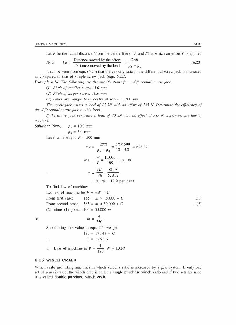
SIMPLE MACHINES 219
Let R be the radial distance (from the centre line of A and B) at which an effort P is applied
Now, VR = Distance moved by the effort
Distance moved by the load =
2πR
p pA B−...(6.23)
It can be seen from eqn. (6.23) that the velocity ratio in the differential screw jack is increasedas compared to that of simple screw jack (eqn. 6.22).Example 6.16. The following are the specifications for a differential screw jack:
(1) Pitch of smaller screw, 5.0 mm
(2) Pitch of larger screw, 10.0 mm
(3) Lever arm length from centre of screw = 500 mm.
The screw jack raises a load of 15 kN with an effort of 185 N. Determine the efficiency ofthe differential screw jack at this load.
If the above jack can raise a load of 40 kN with an effort of 585 N, determine the law ofmachine.
Solution: Now, pA = 10.0 mm
pB = 5.0 mmLever arm length, R = 500 mm
VR = 2 2 500
10 5 0
π πR
p pA B−= ×
− . = 628.32
MA = W
P= 15 000
185
, = 81.08
∴ η = MA
VR= 81 08
628 32
.
.
= 0.129 = 12.9 per cent.To find law of machine:
Let law of machine be P = mW + C
From first case: 185 = m × 15,000 + C ...(1)From second case: 585 = m × 50,000 + C ...(2)
(2) minus (1) gives, 400 = 35,000 m.
or m = 4
350
Substituting this value in eqn. (1), we get
185 = 171.43 + C
∴ C = 13.57 N
∴ Law of machine is P = 4
350 W + 13.57
6.15 WINCH CRABS
Winch crabs are lifting machines in which velocity ratio is increased by a gear system. If only oneset of gears is used, the winch crab is called a single purchase winch crab and if two sets are usedit is called double purchase winch crab.
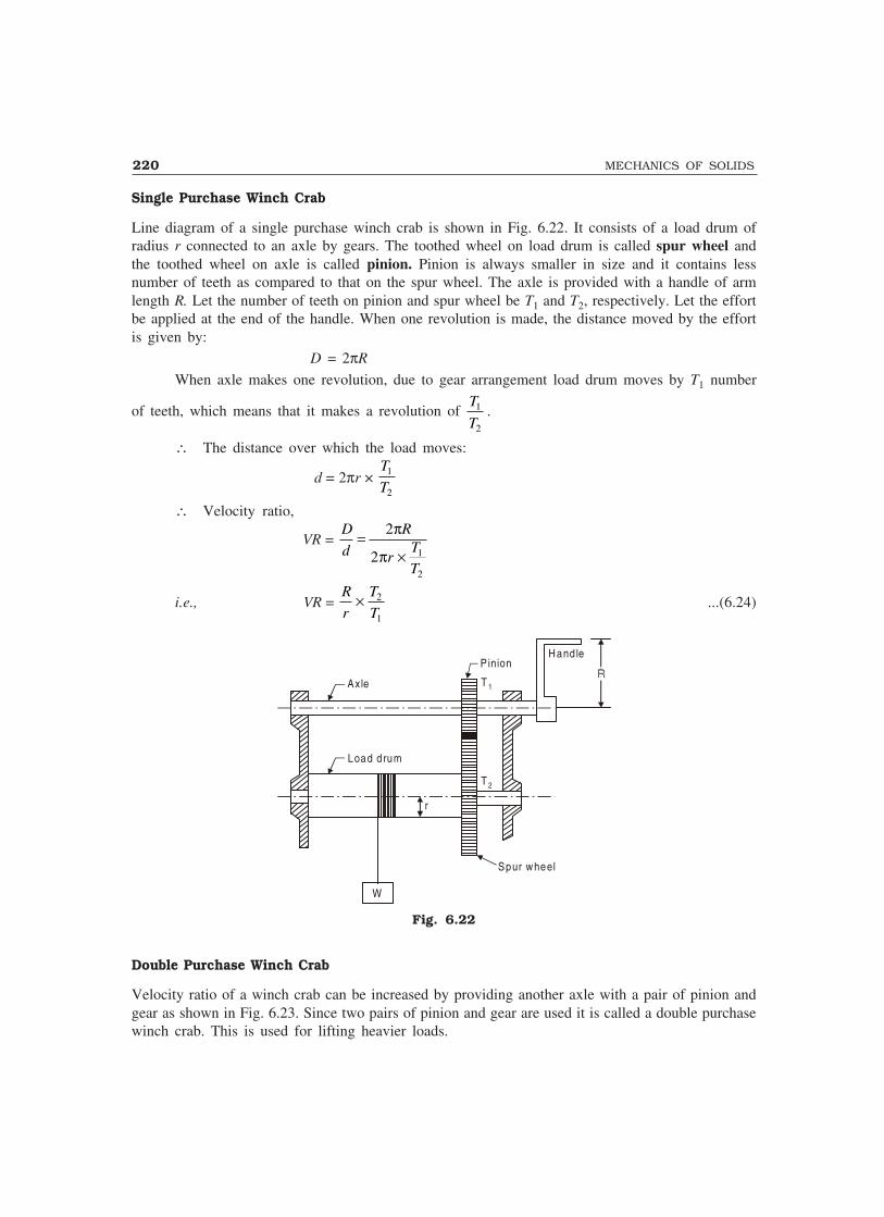
220 MECHANICS OF SOLIDS
Single Purchase Winch Crab
Line diagram of a single purchase winch crab is shown in Fig. 6.22. It consists of a load drum ofradius r connected to an axle by gears. The toothed wheel on load drum is called spur wheel andthe toothed wheel on axle is called pinion. Pinion is always smaller in size and it contains lessnumber of teeth as compared to that on the spur wheel. The axle is provided with a handle of armlength R. Let the number of teeth on pinion and spur wheel be T1 and T2, respectively. Let the effortbe applied at the end of the handle. When one revolution is made, the distance moved by the effortis given by:
D = 2πR
When axle makes one revolution, due to gear arrangement load drum moves by T1 number
of teeth, which means that it makes a revolution of T
T1
2
.
∴ The distance over which the load moves:
d = 2πr × T
T1
2
∴ Velocity ratio,
VR = D
d
R
rT
T
=×
2
2 1
2
π
π
i.e., VR = R
r
T
T× 2
1
...(6.24)
Axle
Load drum
Pinion
T 1
T 2
Hand le
Spur wheel
W
r
Fig. 6.22
Double Purchase Winch Crab
Velocity ratio of a winch crab can be increased by providing another axle with a pair of pinion andgear as shown in Fig. 6.23. Since two pairs of pinion and gear are used it is called a double purchasewinch crab. This is used for lifting heavier loads.
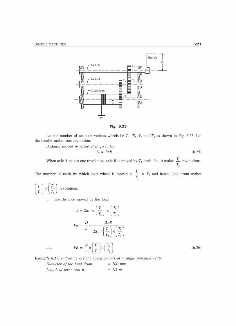
SIMPLE MACHINES 221
Axle -A
Axle -B
Load drum
r
T 1
T2T3
T 4
Hand le
W
Fig. 6.23
Let the number of teeth on various wheels be T1, T2, T3 and T4 as shown in Fig. 6.23. Letthe handle makes one revolution.
Distance moved by effort P is given by:D = 2πR ...(6.25)
When axle A makes one revolution, axle B is moved by T1 teeth, i.e., it makes T
T1
2
revolutions.
The number of teeth by which spur wheel is moved is T
T1
2
× T3 and hence load drum makes
T
T1
2
�
�
��×
T
T3
4
�
�
�� revolutions.
∴ The distance moved by the load
d = 2πr × T
T1
2
�
�
�� ×
T
T3
4
�
�
��
VR = D
d
R
rT
T
T
T
=����
����
2
2 1
2
3
4
π
π
i.e., VR = R
r
T
T
T
T�
�
���
�
��2
1
4
3
...(6.26)
Example 6.17. Following are the specifications of a single purchase crab:
Diameter of the load drum = 200 mm
Length of lever arm R = 1.2 m

222 MECHANICS OF SOLIDS
Number of teeth on pinion, T1 = 10
Number of teeth on spur wheel, T2 = 100.
Find the velocity ratio of this machine. On this machine efforts of 100 N and 160 N are requiredto lift the load of 3 kN and 9 kN, respectively. Find the law of the machine and the efficiencies atthe above loads.
Solution: Radius of the load drum, r = 200
2 = 100 mm
Length of lever arm, R = 1.2 m = 1200 mmVelocity ratio of the single purchase crab is given by:
VR = R
r
T
T× 2
1
= 1200
100
100
10×
VR = 120Let the law of machine be P = mW + C
In first case: P = 100 N; W = 3 kN = 3000 N∴ 100 = m × 3000 + C ...(1)
In the second case: P = 160 N; and W = 9 kN = 9000 N∴ 160 = m × 9000 + C ...(2)Subtracting eqn. (1) from eqn. (2), we get
60 = 6000 m
∴ m = 1
100 = 0.01
Substituting this value of m in eqn. (1), we get
100 = 1
100 × 3000 + C
∴ C = 70Hence, the law of machine is
P = 0.01 W + 70Efficiencies:
In the first case,
MA = W
P= 3000
100 = 30
∴ η = MA
VR= 30
120 = 0.25 = 25%
In the second case,
MA = W
P= 9000
160 = 56.25
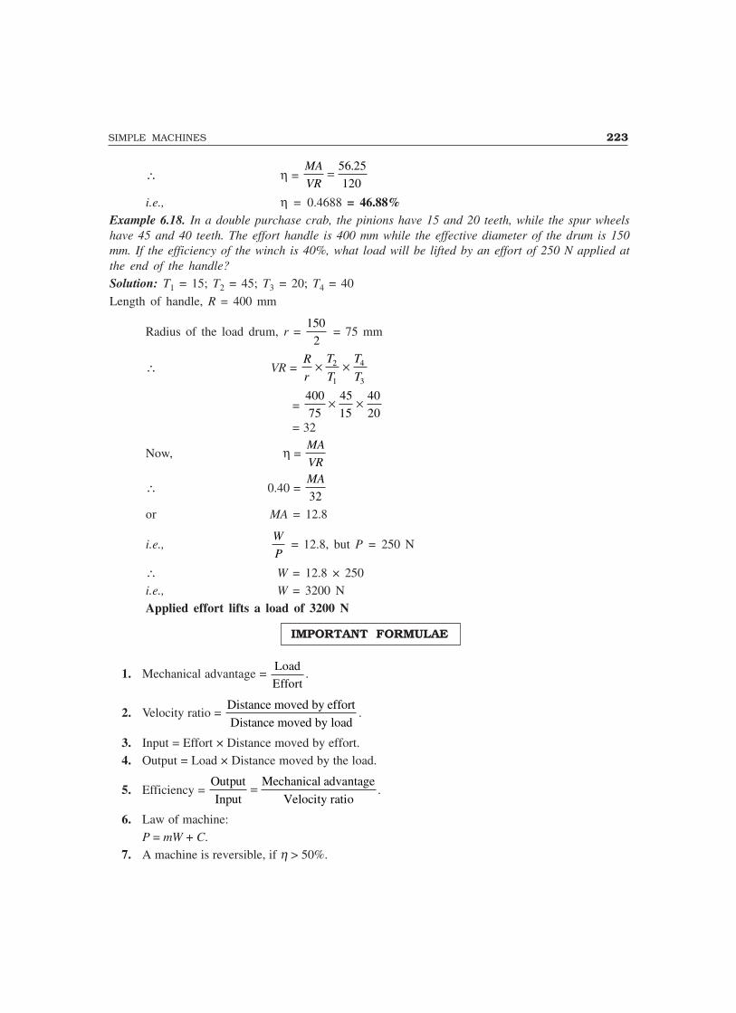
SIMPLE MACHINES 223
∴ η = MA
VR= 56 25
120
.
i.e., η = 0.4688 = 46.88%Example 6.18. In a double purchase crab, the pinions have 15 and 20 teeth, while the spur wheelshave 45 and 40 teeth. The effort handle is 400 mm while the effective diameter of the drum is 150mm. If the efficiency of the winch is 40%, what load will be lifted by an effort of 250 N applied atthe end of the handle?
Solution: T1 = 15; T2 = 45; T3 = 20; T4 = 40
Length of handle, R = 400 mm
Radius of the load drum, r = 150
2 = 75 mm
∴ VR = R
r
T
T
T
T× ×2
1
4
3
= 400
75
45
15
40
20× ×
= 32
Now, η = MA
VR
∴ 0.40 = MA
32
or MA = 12.8
i.e.,W
P = 12.8, but P = 250 N
∴ W = 12.8 × 250i.e., W = 3200 NApplied effort lifts a load of 3200 N
IMPORTANT FORMULAE
1. Mechanical advantage = Load
Effort.
2. Velocity ratio = Distance moved by effort
Distance moved by load.
3. Input = Effort × Distance moved by effort.4. Output = Load × Distance moved by the load.
5. Efficiency = Output
Input
Mechanical advantage
Velocity ratio= .
6. Law of machine:P = mW + C.
7. A machine is reversible, if η > 50%.

224 MECHANICS OF SOLIDS
8. In case of first order pulleys,VR = 2n, where n is the number of movable pulleys.
9. In case of second order pulleys,VR = 2n, is the where n is number of pulleys.
10. In case of third order pulleysVR = 2n – 1, where n is number of pulleys.
11. In wheel and axle,
VR = Diameter of wheel
Diameter of axle.
12. In case of wheel and differential axle,
VR = 2D
d d2 1−.
13. In Weston differential pulley block,
VR = 2D
D d−.
14. In inclined plane
VR = 1
sin θ15. In screw jack
VR = 2πR
p.
16. In double purchase winch crab
VR = R
r
T
T
T
T× ×2
1
4
3.
17. In single purchase winch crab
VR = R
r
T
T× 2
1
.
THEORY QUESTIONS
1. Define the following terms:
(i) Mechanical advantage(ii) Velocity ratio
(iii) Efficiency of a lifting machine.2. Explain the law of machine. How it is determined ?3. What is meant by reversibility of machine ? Prove that a machine is reversible if its efficiency is
more than 50%.

SIMPLE MACHINES 225
4. With neat sketches explain the different types of pulley systems and derive the expressions fortheir efficiency.
5. With neat sketches explain the following simple machines:
(i) Wheel and axle(ii) Wheel and differential axle
(iii) Weston differential pulley block.
6. Show that in a screw jack effort P required to lift a load W is given by P = d
RW
2 1
µ θµ θ
+−
tan
tan
where φ is angle of friction and tan θ = p
dπ, p being the pitch of screw.
7. Give a neat sketch of
(i) Single purchase winch crab(ii) Double purchase winch crab
PROBLEMS FOR EXERCISE
1. In a lifting machine an effort of 1.5 kN is to be moved through a distance of 7.2 m to move a loadof 24 kN through a distance of 300 mm. Determine: (1) mechanical advantage, (2) velocity ratio,(3) efficiency, (4) ideal effort, (5) effort lost in friction, (6) ideal load and (7) frictional resistance.
[Ans. (1) 16; (2) 24; (3) 66.67%; (4) 1.0 kN; (5) 0.5 kN; (6) 36 kN and (7) 12 kN]2. In a lifting machine an effort of 400 N is required to raise a load of 3000 N and an effort of 640 N,
to raise a load of 5000 N. How much load can be lifted with an effort of 760 N? If the velocityratio is 16, determine the efficiency of the machine when an effort of 760 N is applied. Is it areversible machine? [Ans. W = 6000 N; η = 49.34; It is not reversible]
3. The following observations were made in an experiment on a lifting machine:
Load in N 500 1000 1500 2000 2500 3000Effort in N 26 47 76 95 105 127
Draw the load versus effort graph and determine the law of machine. If the velocity ratio is 30determine the efficiency while lifting a load of 1800 N.What is the maximum efficiency of the machine ?
[Ans. P = 0.04W + 6; η = 51.28%; maximum η = 83.33%]
4. A lifting machine having velocity ratio 28 starts raising a load of 6420 N on applying an effort of450 N to it. If suddenly the effort is removed find whether the load comes down or not?
[Ans. η = 50.95%, hence the load comes down]5. In the first order pulley system having three movable pulleys, how much effort is required to
raise a load of 5780 N if the same system raises a load of 1200 N with an effort of 200 N? Assumethe efficiency to be constant for the pulley system. [Ans. P = 963.33 N]
6. For the arrangement of pulleys shown in Fig. 6.24, find the effort required to raise the given load7280 N. Assume efficiency of the system as 75%. [Ans. P = 2436.7 N]
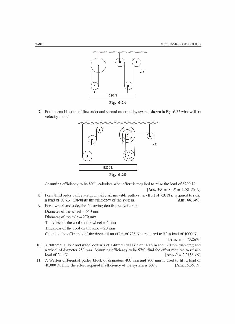
226 MECHANICS OF SOLIDS
P
1280 N
Fig. 6.24
7. For the combination of first order and second order pulley system shown in Fig. 6.25 what will bevelocity ratio?
8200 N
P
Fig. 6.25
Assuming efficiency to be 80%, calculate what effort is required to raise the load of 8200 N.
[Ans. VR = 8; P = 1281.25 N]8. For a third order pulley system having six movable pulleys, an effort of 720 N is required to raise
a load of 30 kN. Calculate the efficiency of the system. [Ans. 66.14%]9. For a wheel and axle, the following details are available:
Diameter of the wheel = 540 mmDiameter of the axle = 270 mmThickness of the cord on the wheel = 6 mmThickness of the cord on the axle = 20 mmCalculate the efficiency of the device if an effort of 725 N is required to lift a load of 1000 N.
[Ans. η = 73.26%]10. A differential axle and wheel consists of a differential axle of 240 mm and 320 mm diameter; and
a wheel of diameter 750 mm. Assuming efficiency to be 57%, find the effort required to raise aload of 24 kN. [Ans. P = 2.2456 kN]
11. A Weston differential pulley block of diameters 400 mm and 800 mm is used to lift a load of40,000 N. Find the effort required if efficiency of the system is 60%. [Ans. 26,667 N]
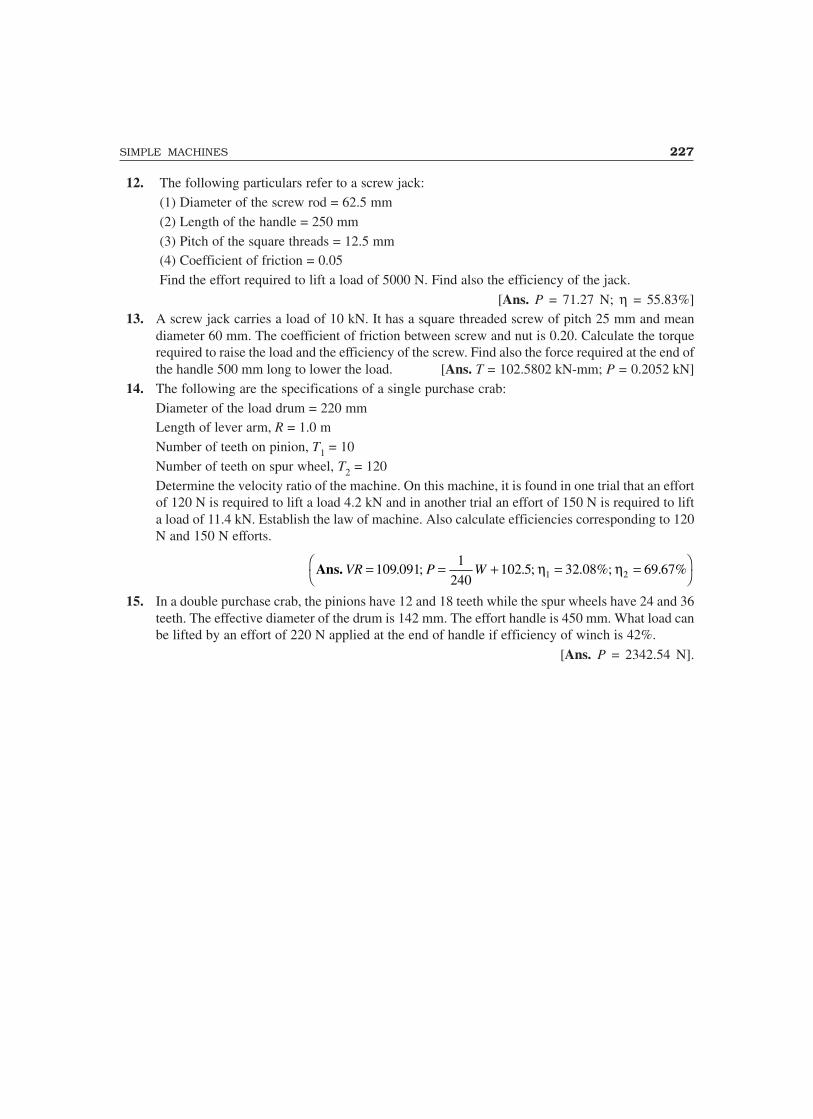
SIMPLE MACHINES 227
12. The following particulars refer to a screw jack:(1) Diameter of the screw rod = 62.5 mm(2) Length of the handle = 250 mm(3) Pitch of the square threads = 12.5 mm(4) Coefficient of friction = 0.05Find the effort required to lift a load of 5000 N. Find also the efficiency of the jack.
[Ans. P = 71.27 N; η = 55.83%]13. A screw jack carries a load of 10 kN. It has a square threaded screw of pitch 25 mm and mean
diameter 60 mm. The coefficient of friction between screw and nut is 0.20. Calculate the torquerequired to raise the load and the efficiency of the screw. Find also the force required at the end ofthe handle 500 mm long to lower the load. [Ans. T = 102.5802 kN-mm; P = 0.2052 kN]
14. The following are the specifications of a single purchase crab:Diameter of the load drum = 220 mmLength of lever arm, R = 1.0 mNumber of teeth on pinion, T1 = 10Number of teeth on spur wheel, T2 = 120Determine the velocity ratio of the machine. On this machine, it is found in one trial that an effortof 120 N is required to lift a load 4.2 kN and in another trial an effort of 150 N is required to lifta load of 11.4 kN. Establish the law of machine. Also calculate efficiencies corresponding to 120N and 150 N efforts.
Ans. VR P W= = + = =��
�
109 0911
240102 5 32 08%; 69 67%1 2. ; . ; . .η η
15. In a double purchase crab, the pinions have 12 and 18 teeth while the spur wheels have 24 and 36teeth. The effective diameter of the drum is 142 mm. The effort handle is 450 mm. What load canbe lifted by an effort of 220 N applied at the end of handle if efficiency of winch is 42%.
[Ans. P = 2342.54 N].

7Physical and Mechanical
Properties of Structural Materials
The principle materials used in building structures and machines include metals and their alloys,concrete, wood, stones, bricks and other clay products, bituminous materials and plastics. The productsfinally produced with these materials should be strong enough to resist the forces coming on itwithout undergoing deformation so as to put it out of use. The product should be durable. Therequired properties for different usage is different. Hence an engineer must know the requiredproperties for his products. Various properties of materials may be grouped into:
(a) Physical Properties(b) Mechanical Properties.
7.1 PHYSICAL PROPERTIES
The various physical properties of the materials are briefly explained below:1. Density: It is defined as mass of a material per unit volume. Kilogram is the unit of mass
in SI system. It is found by weighing the material without voids.
2. Bulk density or unit weight: It is defined as weight of material per unit volume. Its unitin SI is kN/m3. Volume of the material is found from the natural state of material i.e. fromvolume of voids and solids together.
3. Specific gravity: It is the ratio of density of materials to the unit weight of water. It maybe noted that for water density and unit weight are one and the same. Specific gravity is adimensionless quantity.
4. Porosity: It is the ratio of the volume of voids to the volume of granular materials.5. Hygroscopy: It is the property of the material to absorb water from the atmosphere. Timber
possesses this property.6. Water absorption: It is the porperty of the material to absorb water and retain it. It is
expressed as percentage in weight of absorbed water to weight of dry material. Concrete andbricks possess this property to significant extent.
7. Permeability: It is the property of material by virtue of which it allow water to flow throughit. Soil possesses this property and materials like bitumen and metals are impervious.
8. Weather resistance: It is the ability to sustain alternating changes in wet and dry conditionsof weather. We look for materials with good weather resistance without undergoingconsiderable changes in dimensions and loosing mechanical strength.
9. Frost resistance: It is the property to resist repeated freezing and throwing of absorbedwater without losing mechanical strength.
228

PHYSICAL AND MECHANICAL PROPERTIES OF STRUCTURAL MATERIALS 229229229229229
10. Thermal conductivity: It is the ability of the material to transfer heat. Metals have higherthermal conductivity. Moist materials have higher heat conductivity compared to dry porousmaterials. Rubber is having very low thermal conductivity.
11. Thermal resistivity: It is the reciprocal of thermal conductivity and is defined as time takenfor the flow of unit heat.
12. Fire resistance: It is the property by virtue of which a material resists the action of hightemperature without undergoing substantial changes in shape and loss of strength. Steel haspoor fire resistance. Concrete is better than steel in resisting fire. Bricks are having verygood fire resistance.
13. Sound absorption: It is the property of reducing the reflection of sound waves. Porousmaterials have better sound absorption property. In auditoriums and cinema halls we haveto look for materials with good sound absorption properties.
14. Chemical resistance: It is the ability of the material to withstand the action of acids,alkalies, gases etc. Materials are subjected to the action of these chemicals, which are presentin air or water or land. Stone and wood have poor resistance to chemical actions while brickshave good chemical resistance.
15. Corrosion: It is the destruction of the material due to slow oxidation. Steel is susceptibleto corrosion. The corrosion rate is high in marine environment.
16. Soundness: A material is said to be sound, if it has good resistance to heat, alternatefreezing and thawing and the other destructive actions of the atmosphere.
17. Durability: It is the ability to resist the combined effects of atmosphere, rain and othereffects and maintain the original strength characters for a long period.
7.2 MECHANICAL PROPERTIES
Resistance to various applied forces is referred as mechanical properties. Some of these propertiesare briefly presented below:
1. Properties related to axial loading: For designing structural elements to resist the appliedloads, the following strength properties should be known:
(a) Tensile strength: If an element is subjected to pulling forces, the resistance developed perunit area is termed as tensile stress and the maximum trensile stress the material can resistis termed as tensile strength. To find the resisting forces developed a section plane may betaken through the element and the equilibrium of any one part may be considered. Each partis in equilibrium under the action of applied forces and internal resisting forces. Fig. 7.1
P P
P pA
(a)
(b)
(c)
pA pA
Fig. 7.1
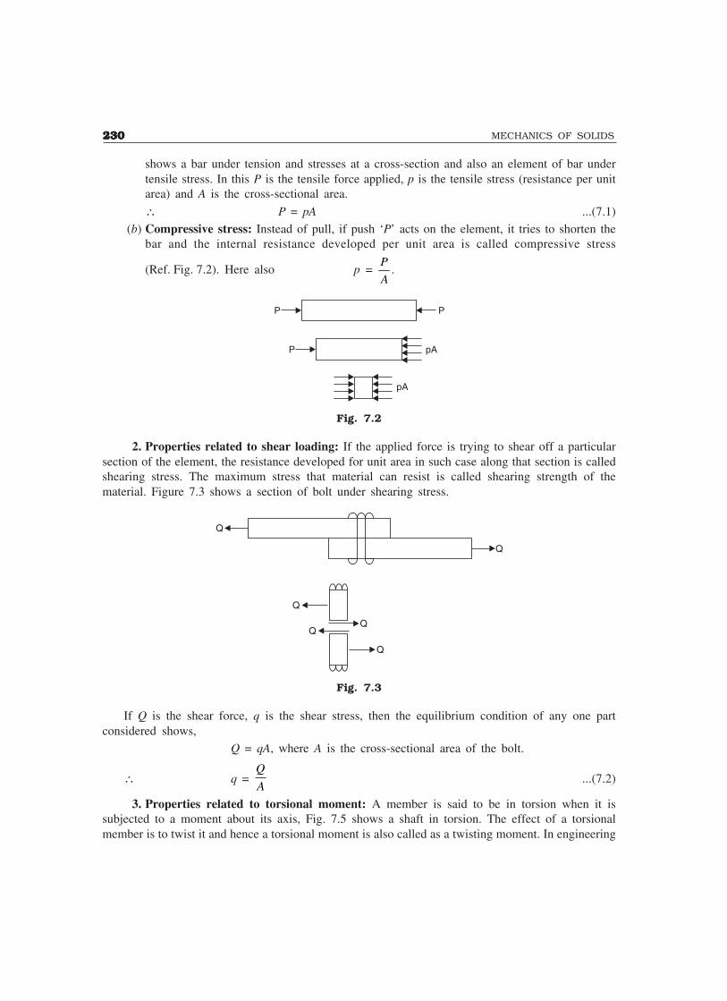
230230230230230 MECHANICS OF SOLIDS
shows a bar under tension and stresses at a cross-section and also an element of bar undertensile stress. In this P is the tensile force applied, p is the tensile stress (resistance per unitarea) and A is the cross-sectional area.
∴ P = pA ...(7.1)(b) Compressive stress: Instead of pull, if push ‘P’ acts on the element, it tries to shorten the
bar and the internal resistance developed per unit area is called compressive stress
(Ref. Fig. 7.2). Here also p = P
A.
P P
P pA
pA
Fig. 7.2
2. Properties related to shear loading: If the applied force is trying to shear off a particularsection of the element, the resistance developed for unit area in such case along that section is calledshearing stress. The maximum stress that material can resist is called shearing strength of thematerial. Figure 7.3 shows a section of bolt under shearing stress.
Q
Q
Q
Q
Fig. 7.3
If Q is the shear force, q is the shear stress, then the equilibrium condition of any one partconsidered shows,
Q = qA, where A is the cross-sectional area of the bolt.
∴ q = Q
A...(7.2)
3. Properties related to torsional moment: A member is said to be in torsion when it issubjected to a moment about its axis, Fig. 7.5 shows a shaft in torsion. The effect of a torsionalmember is to twist it and hence a torsional moment is also called as a twisting moment. In engineering

PHYSICAL AND MECHANICAL PROPERTIES OF STRUCTURAL MATERIALS 231231231231231
problems many members are subjected to torsion. Shafts transmitting power from engine to rear axleof automobile, from a motor to machine tool and from a turbine to electric motor are the commonexamples of members in torsion. Ring beams of circular water tanks and beams of grid floors arealso the examples of members in torsion. The applied torsion is resisted by the material of themember by developing shear stresses. This shear stress varies linearly from zero at centre of the shaftto the maximum value at the extreme fibre.
T
T
da
qda
T = qrdaΣ
r
Fig. 7.4
4. Properties related to bending: When a member is supported at two or more points andsubjected to transverse load it bends and develops resistance to the load. The cross-sections of themembers are subjected to bending moment and shear force. Finally the load gets transferred to thesupport by end shear. The shear force introduces shear stresses in the material while bending momentintroduces tension in some parts and compression in other parts as shown in Fig. 7.5.
P1 P2 P3
M
M
F
(a) Beam
(b) Bending moment and shear force at a section
F
F
M M
(c) Resistance to shear
(d) Resistance to bending
Fig. 7.5

232232232232232 MECHANICS OF SOLIDS
5. Fatigue: Many structural memberes are subjected to fluctuation and reversal of stresses asshown in Fig. 7.6 (a) and (b). A bridge deck is a common example of fluctuation of stresses andthe shaft is the mechanical component subjected to reversal of stresses. This type of stress whenapplied repeatedly reduces the strength of material and this effect is called fatigue. This property isshown in Fig. 7.6 (c). The maximum stress at which even a billion reversal of stresses cannot causefailure of the material is called endurance limit.
No. of cycles
Str
ess
O
No. of cycles
Str
ess O
(a) Fluctuation of stress
(b) Reversal of stress
No. of cycles
Bre
akin
gst
ress
B
A A - Static breaking stressB - Endurance limit
(c) Breaking stress vs No. of cycles.
Fig. 7.6
6. Abrasive resistance: This is the property by virtue of which a material resists the forcesacting at contact surfaces when one material rubs/moves over the other. This is an important propertyto be studied for the materials used for road surfaces and flooring.
7. Impact strength: This property refers to the ability of the material to resist shock loads dueto heavy loads falling on the surface.
8. Hardness: It is the ability of the material to resist penetration from another material. Anumber called hardness number is used to measure hardness of various materials. It is based onhardnesses of ten minerals arranged in the increasing hardness. Diamond has hardness number 10.Sometimes hardness is measured by size of indentation of steel balls under standard pressure usinghardness testing machine.

PHYSICAL AND MECHANICAL PROPERTIES OF STRUCTURAL MATERIALS 233233233233233
9. Elasticity: It is the property of the material by virtue of which it regains its original shapeand size after the removal of external load. The maximum stress level before which if the load isremoved the material regains its shape and size fully is called its elastic limit.
10. Plasticity: It is the property of the material to retain its changed shape and size after theloads are removed. It is a required property when a material is to be moulded into different shape.
11. Creep: It is the property of the material by virtue of which it undergoes changes in size withtime under the action of constant load. Concrete possesses this property.
12. Toughness: It is the property of a material whereby it absorbs energy due to strainingactions by undergoing plastic deformation.
The other terms proof stress, factor of safety, working stress and load factors are explained inthe next chapter after explaining the stress strain curves. There are standard tests specified by codesto quantity various properties of the materials. Knowing the requirements of materials properties fordifferent purposes, the engineer has to select or reject the materials to be used in construction.
THEORY QUESTIONS
1. Explain the terms:Weather resistance, frost resistance, thermal resistance and fire resistance.
2. What do you understand by the terms: sound absorption, soundness, corrosion resistance anddurability ?
3. Differentiate between:
(a) Impact strength and toughness (b) Elasticity and plasticity(c) Tensile stress and shear stress.

8Simple Stresses and Strains
In this chapter general meaning of stress is explained. Expressions for stresses and strains is derivedwith the following assumptions:
1. For the range of forces applied the material is elastic i.e. it can regain its original shape andsize, if the applied force is removed.
2. Material is homogeneous i.e. every particle of the material possesses identical mechanicalproperties.
3. Material is isotropic i.e. the material possesses identical mechanical property at any point inany direction.Presenting the typical stress-strain curve for a typical steel, the commonly referred terms like
limits of elasticity and proportionality, yield points, ultimate strength and strain hardening are explained.Linear elastic theory is developed to analyse different types of members subject to axial, shear,
thermal and hoop stresses.
8.1 MEANING OF STRESS
When a member is subjected to loads it develops resisting forces. To find the resisting forcesdeveloped a section plane may be passed through the member and equilibrium of any one part maybe considered. Each part is in equilibrium under the action of applied forces and internal resistingforces. The resisting forces may be conveniently split into normal and parallel to the section plane.The resisting force parallel to the plane is called shearing resistance. The intensity of resisting forcenormal to the sectional plane is called intensity of Normal Stress (Ref. Fig. 8.1).
Resisting ForceNormal to Plane
ShearingForce
SectionPlane
p
q
(a) MembersSubject to Forces
(b) Internal ResistancesDeveloped
(c)
Fig. 8.1
234
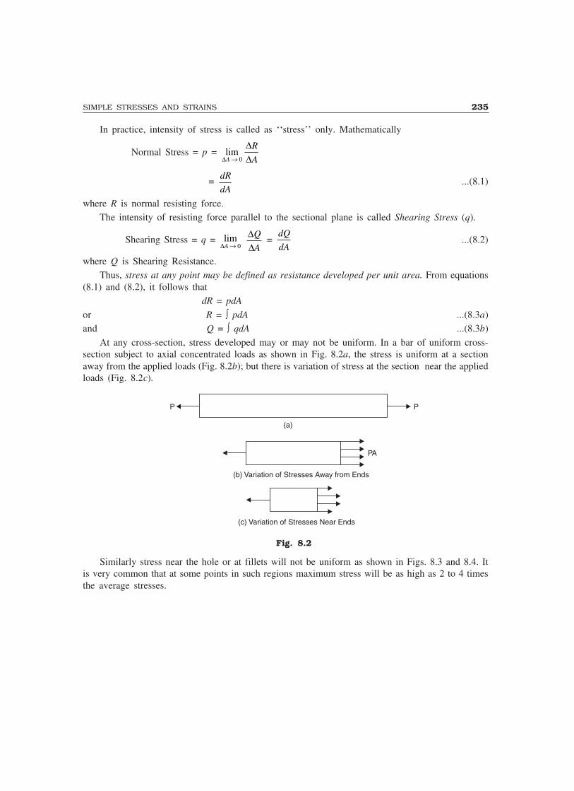
SIMPLE STRESSES AND STRAINS 235
In practice, intensity of stress is called as ‘‘stress’’ only. Mathematically
Normal Stress = p = lim∆
∆∆A
R
A→ 0
= dR
dA...(8.1)
where R is normal resisting force.The intensity of resisting force parallel to the sectional plane is called Shearing Stress (q).
Shearing Stress = q = lim∆A → 0
∆∆
Q
A =
dQ
dA...(8.2)
where Q is Shearing Resistance.Thus, stress at any point may be defined as resistance developed per unit area. From equations
(8.1) and (8.2), it follows that dR = pdA
or R = ∫ pdA ...(8.3a)and Q = ∫ qdA ...(8.3b)
At any cross-section, stress developed may or may not be uniform. In a bar of uniform cross-section subject to axial concentrated loads as shown in Fig. 8.2a, the stress is uniform at a sectionaway from the applied loads (Fig. 8.2b); but there is variation of stress at the section near the appliedloads (Fig. 8.2c).
P P
PA
(b) Variation of Stresses Away from Ends
(a)
(c) Variation of Stresses Near Ends
Fig. 8.2
Similarly stress near the hole or at fillets will not be uniform as shown in Figs. 8.3 and 8.4. Itis very common that at some points in such regions maximum stress will be as high as 2 to 4 timesthe average stresses.
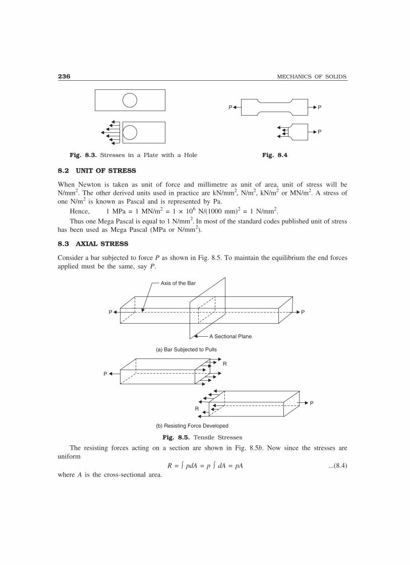
236 MECHANICS OF SOLIDS
P
P
P
Fig. 8.3. Stresses in a Plate with a Hole Fig. 8.4
8.2 UNIT OF STRESS
When Newton is taken as unit of force and millimetre as unit of area, unit of stress will beN/mm2. The other derived units used in practice are kN/mm2, N/m2, kN/m2 or MN/m2. A stress ofone N/m2 is known as Pascal and is represented by Pa.
Hence, 1 MPa = 1 MN/m2 = 1 × 10⁶ N/(1000 mm)2 = 1 N/mm2.
Thus one Mega Pascal is equal to 1 N/mm2. In most of the standard codes published unit of stresshas been used as Mega Pascal (MPa or N/mm2).
8.3 AXIAL STRESS
Consider a bar subjected to force P as shown in Fig. 8.5. To maintain the equilibrium the end forcesapplied must be the same, say P.
Axis of the Bar
P P
A Sectional Plane
R
P
RP
(a) Bar Subjected to Pulls
(b) Resisting Force Developed
Fig. 8.5. Tensile Stresses
The resisting forces acting on a section are shown in Fig. 8.5b. Now since the stresses areuniform
R = ∫ pdA = p ∫ dA = pA ...(8.4)where A is the cross-sectional area.
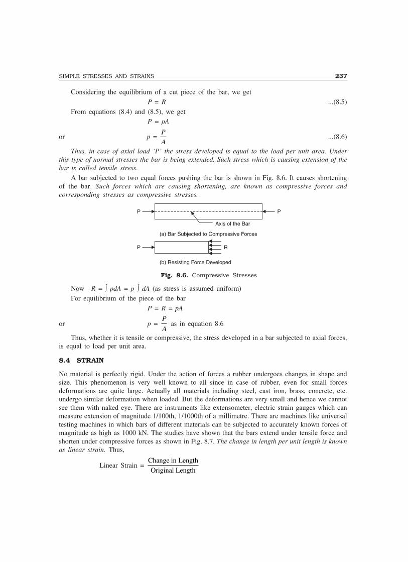
SIMPLE STRESSES AND STRAINS 237
Considering the equilibrium of a cut piece of the bar, we get
P = R ...(8.5)From equations (8.4) and (8.5), we get
P = pA
or p = P
A...(8.6)
Thus, in case of axial load ‘P’ the stress developed is equal to the load per unit area. Underthis type of normal stresses the bar is being extended. Such stress which is causing extension of thebar is called tensile stress.
A bar subjected to two equal forces pushing the bar is shown in Fig. 8.6. It causes shorteningof the bar. Such forces which are causing shortening, are known as compressive forces andcorresponding stresses as compressive stresses.
P
P R
P
(a) Bar Subjected to Compressive Forces
Axis of the Bar
(b) Resisting Force Developed
Fig. 8.6. Compressive Stresses
Now R = ∫ pdA = p ∫ dA (as stress is assumed uniform)For equilibrium of the piece of the bar
P = R = pA
or p = P
A as in equation 8.6
Thus, whether it is tensile or compressive, the stress developed in a bar subjected to axial forces,is equal to load per unit area.
8.4 STRAIN
No material is perfectly rigid. Under the action of forces a rubber undergoes changes in shape andsize. This phenomenon is very well known to all since in case of rubber, even for small forcesdeformations are quite large. Actually all materials including steel, cast iron, brass, concrete, etc.undergo similar deformation when loaded. But the deformations are very small and hence we cannotsee them with naked eye. There are instruments like extensometer, electric strain gauges which canmeasure extension of magnitude 1/100th, 1/1000th of a millimetre. There are machines like universaltesting machines in which bars of different materials can be subjected to accurately known forces ofmagnitude as high as 1000 kN. The studies have shown that the bars extend under tensile force andshorten under compressive forces as shown in Fig. 8.7. The change in length per unit length is knownas linear strain. Thus,
Linear Strain = Change in Length
Original Length

238 MECHANICS OF SOLIDS
e = ∆L
...(8.7)
LL
b¢
(Original Length)
(Shortening)
b
(Extension)
LL
b¢ b
b
(Original Length)
Fig. 8.7
When changes in longitudinal direction is taking place changes in lateral direction also takeplace. The nature of these changes in lateral direction are exactly opposite to that of changes inlongitudinal direction i.e., if extension is taking place in longitudinal direction, the shortening oflateral dimension takes place and if shortening is taking place in longitudinal direction extensiontakes place in lateral directions (See Fig. 8.7). The lateral strain may be defined as changes in thelateral dimension per unit lateral dimension. Thus,
Lateral Strain = Change in Lateral Dimension
Original Lateral Dimension
= ′ − =b b
b
b
b
δ...(8.8)
8.5 STRESS-STRAIN RELATION
The stress-strain relation of any material is obtained by conducting tension test in the laboratorieson standard specimen. Different materials behave differently and their behaviour in tension and incompression differ slightly.
8.5.1 Behaviour in Tension
Mild steel. Figure 8.8 shows a typical tensile test specimen of mild steel. Its ends are gripped intouniversal testing machine. Extensometer is fitted to test specimen which measures extension over thelength L1, shown in Fig. 8.8. The length over which extension is mesured is called gauge length.The load is applied gradually and at regular interval of loads extension is measured. After certainload, extension increases at faster rate and the capacity of extensometer to measure extension comesto an end and, hence, it is removed before this stage is reached and extension is measured from scaleon the universal testing machine. Load is increased gradually till the specimen breaks.

SIMPLE STRESSES AND STRAINS 239
L1L1 L2L2CupCone
Fig. 8.8. Tension Test Specimen Fig. 8.9. Tension Test Specimen after Breaking
Load divided by original cross-sectional areais called as nominal stress or simply as stress.Strain is obtained by dividing extensometerreadings by gauge length of extensometer (L1)and by dividing scale readings by grip to griplength of the specimen (L2). Figure 8.10 showsstress vs strain diagram for the typical mild steelspecimen. The following salient points areobserved on stress-strain curve:
(a) Limit of Proportionality (A): It is thelimiting value of the stress up to whichstress is proportional to strain.
(b) Elastic Limit: This is the limiting valueof stress up to which if the material isstressed and then released (unloaded) strain disappears completely and the original lengthis regained. This point is slightly beyond the limit of proportionality.
(c) Upper Yield Point (B): This is the stress at which, the load starts reducing and the extensionincreases. This phenomenon is called yielding of material. At this stage strain is about 0.125per cent and stress is about 250 N/mm2.
(d) Lower Yield Point (C): At this stage the stress remains same but strain increases for sometime.
(e) Ultimate Stress (D): This is the maximum stress the material can resist. This stress is about370–400 N/mm2. At this stage cross-sectional area at a particular section starts reducing veryfast (Fig. 8.9). This is called neck formation. After this stage load resisted and hence thestress developed starts reducing.
(f) Breaking Point (E): The stress at which finally the specimen fails is called breaking point.At this strain is 20 to 25 per cent.
If unloading is made within elastic limit the original length is regained i.e., the stress-strain curve
E
DF
B
CA
0 F� Strain
Str
ess
Fig. 8.10
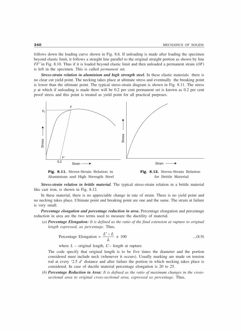
240 MECHANICS OF SOLIDS
follows down the loading curve shown in Fig. 8.6. If unloading is made after loading the specimenbeyond elastic limit, it follows a straight line parallel to the original straight portion as shown by lineFF′ in Fig. 8.10. Thus if it is loaded beyond elastic limit and then unloaded a permanent strain (OF)is left in the specimen. This is called permanent set.
Stress-strain relation in aluminium and high strength steel. In these elastic materials there isno clear cut yield point. The necking takes place at ultimate stress and eventually the breaking pointis lower than the ultimate point. The typical stress-strain diagram is shown in Fig. 8.11. The stressp at which if unloading is made there will be 0.2 per cent permanent set is known as 0.2 per centproof stress and this point is treated as yield point for all practical purposes.
Fpy
Str
ess
0.2F�
Strain
Str
ess
Strain
Fig. 8.11. Stress-Strain Relation in Fig. 8.12. Stress-Strain RelationAluminium and High Strength Steel for Brittle Material
Stress-strain relation in brittle material. The typical stress-strain relation in a brittle materiallike cast iron, is shown in Fig. 8.12.
In these material, there is no appreciable change in rate of strain. There is no yield point andno necking takes place. Ultimate point and breaking point are one and the same. The strain at failureis very small.
Percentage elongation and percentage reduction in area. Percentage elongation and percentagereduction in area are the two terms used to measure the ductility of material.
(a) Percentage Elongation: It is defined as the ratio of the final extension at rupture to originallength expressed, as percentage. Thus,
Percentage Elongation = L L
L
′ − × 100 ...(8.9)
where L – original length, L′– length at rupture.
The code specify that original length is to be five times the diameter and the portionconsidered must include neck (whenever it occurs). Usually marking are made on tensionrod at every ‘2.5 d’ distance and after failure the portion in which necking takes place isconsidered. In case of ductile material percentage elongation is 20 to 25.
(b) Percentage Reduction in Area: It is defined as the ratio of maximum changes in the cross-sectional area to original cross-sectional area, expressed as percentage. Thus,

SIMPLE STRESSES AND STRAINS 241
Percentage Reduction in Area = A A
A
− ′ × 100 ...(8.10)
where A–original cross-sectional area, A′–minimum cross-sectional area. In case of ductilematerial, A′ is calculated after measuring the diameter at the neck. For this, the two brokenpieces of the specimen are to be kept joining each other properly. For steel, the percentagereduction in area is 60 to 70.
8.5.2 Behaviour of Materials under Compression
As there is chance to bucking (laterally bending) of long specimen, for compression tests shortspecimens are used. Hence, this test involves measurement of smaller changes in length. It resultsinto lesser accuracy. However precise measurements have shown the following results:
(a) In case of ductile materials stress-strain curve follows exactly same path as in tensile testup to and even slightly beyond yield point. For larger values the curves diverge. There willnot be necking in case of compression tests.
(b) For most brittle materials ultimate compresive stress in compression is much larger than intension. It is because of flows and cracks present in brittle materials which weaken thematerial in tension but will not affect the strength in compression.
8.6 NOMINAL STRESS AND TRUE STRESS
So far our discussion on direct stress is based on the value obtained by dividing the load by originalcross-sectional area. That is the reason why the value of stress started dropping after neck is formedin mild steel (or any ductile material) as seen in Fig. 8.10. But actually as material is stressed itscross-sectional area changes. We should divide load by the actual cross-sectional area to get truestress in the material. To distinguish between the two values we introduce the terms nominal stressand true stress and define them as given below:
Nominal Stress = Load
Original Cross-sectional Area...(8.11a)
True Stress = Load
Actual Cross-sectional Area...(8.11b)
So far discussion was based on nominal stress.That is why after neck formation started (after ultimatestress), stress-strain curve started sloping down and thebreaking took place at lower stress (nominal). If weconsider true stress, it is increasing continuously asstrain increases as shown in Fig. 8.13.
Nominal Stress-Strain Curve
True Stress-Strain Curve
Str
ess
Strain
Fig. 8.13. Nominal Stress-Strain Curveand True Stress-Strain Curve for Mild
Steel.

242 MECHANICS OF SOLIDS
8.7 FACTOR OF SAFETY
In practice it is not possible to design a mechanical component or structural component permittingstressing up to ultimate stress for the following reasons:
1. Reliability of material may not be 100 per cent. There may be small spots of flaws.2. The resulting deformation may obstruct the functional performance of the component.
3. The loads taken by designer are only estimated loads. Occasionally there can be overloading.Unexpected impact and temperature loadings may act in the lifetime of the member.
4. There are certain ideal conditions assumed in the analysis (like boundary conditions). Actuallyideal conditions will not be available and, therefore, the calculated stresses will not be 100per cent real stresses.
Hence, the maximum stress to which any member is designed is much less than the ultimatestress, and this stress is called Working Stress. The ratio of ultimate stress to working stress is calledfactor of safety. Thus
Factor of Safety = Ultimate Stress
Working Stress...(8.12)
In case of elastic materials, since excessive deformation create problems in the performance ofthe member, working stress is taken as a factor of yield stress or that of a 0.2 proof stress (if yieldpoint do not exist).
Factor of safety for various materials depends up on their reliability. The following values arecommonly taken in practice:
1. For steel – 1.85
2. For concrete – 33. For timber – 4 to 6
8.8 HOOKE’S LAW
Robert Hooke, an English mathematician conducted several experiments and concluded that stressis proportional to strain up to elastic limit. This is called Hooke’s law. Thus Hooke’s law is, up toelastic limit
p ∝ e ...(8.13a)
where p is stress and e is strain
Hence, p = Ee ...(8.13b)
where E is the constant of proportionality of the material, known as modulus of elasticity or Young’smodulus, named after the English scientist Thomas Young (1773–1829).
However, present day sophisticated experiments have shown that for mild steel the Hooke’s lawholds good up to the proportionality limit which is very close to the elastic limit. For other materials,as seen in art. 1.5, Hooke’s law does not hold good. However, in the range of working stresses,assuming Hooke’s law to hold good, the relationship does not deviate considerably from actualbehaviour. Accepting Hooke’s law to hold good, simplifies the analysis and design procedureconsiderably. Hence Hooke’s law is widely accepted. The analysis procedure accepting Hooke’s lawis known as Linear Analysis and the design procedure is known as the working stress method.

SIMPLE STRESSES AND STRAINS 243
8.9 EXTENSION/SHORTENING OF A BAR
Consider the bars shown in Fig. 8.14
P
LL �
P
P
LL �
P
Fig. 8.14
From equation (8.6), Stress p = P
A
From equation (8.7), Strain, e = ∆L
From Hooke’s Law we have,
E = Stress
Strain= = =p
e
P A
L
PL
A
/
/∆ ∆
or ∆ = PL
AE. ...(8.14)
Example 8.1. A circular rod of diameter 16 mm and 500 mm long is subjected to a tensile force 40kN. The modulus of elasticity for steel may be taken as 200 kN/mm2. Find stress, strain and elongationof the bar due to applied load.
Solution: Load P = 40 kN = 40 × 1000 NE = 200 kN/mm2 = 200 × 103 N/mm2
L = 500 mm Diameter of the rod d = 16 mm
Therefore, sectional area A = π πd 2
4 4= × 162
= 201.06 mm2
Stress p = P
A= ×40 1000
201 06. = 198.94 N/mm2
Strain e = p
E=
×198 94
200 103
.= 0.0009947
Elongation ∆ = PL
AE= × ×
× ×4.0 1000 500
201.06 200 103 = 0.497 mm

244 MECHANICS OF SOLIDS
Example 8.2. A Surveyor’s steel tape 30 m long has a cross-section of 15 mm × 0.75 mm. With this,line AB is measure as 150 m. If the force applied during measurement is 120 N more than the forceapplied at the time of calibration, what is the actual length of the line?
Take modulus of elasticity for steel as 200 kN/mm2.
Solution: A = 15 × 0.75 = 11.25 mm2
P = 120 N, L = 30 m = 30 × 1000 mm
E = 200 kN/mm2 = 200 × 103 N/mm2
Elongation ∆ = PL
AE= × ×
× ×120 30 1000
11.25 200 103 = 1.600 mm
Hence, if measured length is 30 m.
Actual length is 30 m + 1.600 mm = 30.001600 m
∴ Actual length of line AB = 150
30 × 30.001600 = 150.008 m
Example 8.3. A hollow steel tube is to be used to carry an axial compressive load of160 kN. The yield stress for steel is 250 N/mm2. A factor of safety of 1.75 is to be used in the design.The following three class of tubes of external diameter 101.6 mm are available.
Class ThicknessLight 3.65 mm
Medium 4.05 mmHeavy 4.85 mm
Which section do you recommend?
Solution: Yield stress = 250 N/mm2
Factor of safety = 1.75Therefore, permissible stress
p = 250
1 75. = 142.857 N/mm2
Load P = 160 kN = 160 × 103 N
but p = P
A
i.e. 142.857 = 160 103×A
∴ A = 160 10142 857
3×.
= 1120 mm2
For hollow section of outer diameter ‘D’ and inner diameter ‘d’
A = π4
(D2 – d2) = 1120
π4
(101.62 – d2) = 1120
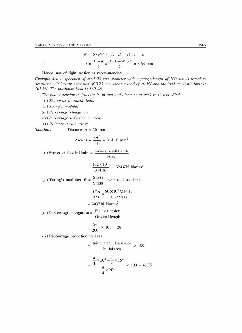
SIMPLE STRESSES AND STRAINS 245
d2 = 8896.53 ∴ d = 94.32 mm
∴ t = D d− = −
2
101.6 94.32
2 = 3.63 mm
Hence, use of light section is recommended.Example 8.4. A specimen of steel 20 mm diameter with a gauge length of 200 mm is tested todestruction. It has an extension of 0.25 mm under a load of 80 kN and the load at elastic limit is102 kN. The maximum load is 130 kN.
The total extension at fracture is 56 mm and diameter at neck is 15 mm. Find
(i) The stress at elastic limit.
(ii) Young’s modulus.
(iii) Percentage elongation.
(iv) Percentage reduction in area.
(v) Ultimate tensile stress.
Solution: Diameter d = 20 mm
Area A = πd 2
4 = 314.16 mm2
(i) Stress at elastic limit = Load at elastic limit
Area
= 102 10
314.16
3× = 324.675 N/mm2
(ii) Young’s modulus E = Stress
Strainwithin elastic limit
= P A
L
/
/
80 10 /314.16
0.25/200
3
∆= ×
= 203718 N/mm2
(iii) Percentage elongation = Final extension
Original length
= 56
200 × 100 = 28
(iv) Percentage reduction in area
= Initial area Final area
Initial area
− × 100
=
π π
π4
204
15
420
2 2
2
× − ×
× × 100 = 43.75

246 MECHANICS OF SOLIDS
(v) Ultimate Tensile Stress = Ultimate Load
Area
= 130 103×314 16.
= 413.80 N/mm2.
8.10 BARS WITH CROSS-SECTIONS VARYING IN STEPS
A typical bar with cross-sections varying in steps and subjected to axial load is as shown in Fig.8.15(a). Let the length of three portions be L1, L2 and L3 and the respective cross-sectional areas ofthe portion be A1, A2, A3 and E be the Young’s modulus of the material and P be the applied axialload.
Figure 8.15(b) shows the forces acting on the cross-sections of the three portions. It is obviousthat to maintain equilibrium the load acting on each portion is P only. Hence stress, strain andextension of each of these portions are as listed below:
P 1 2 3A1
A2A3
P
L1L1 L2L2L3L3
P P P P P
(a)
Section Through 1 Section Through 2 Section Through 3
(b)
Fig. 8.15. Typical Bar with Cross-section Varying in Step
Portion Stress Strain Extension
1 p1 = PA1
e1 = pE
PA E
1
1= ∆1 = PL
A E1
1
2 p2 = P
A2e2 =
pE
PA E
2
2= ∆2 =
PLA E
2
2
3 p3 = PA3
e3 = pE
PA E
3
3= ∆3 =
PLA E
3
3
Hence total change in length of the bar
∆ = ∆1 + ∆2 + ∆3 = PL
A E
PL
A E
PL
A E1
1
2
2
3
3
+ + ...(8.15)
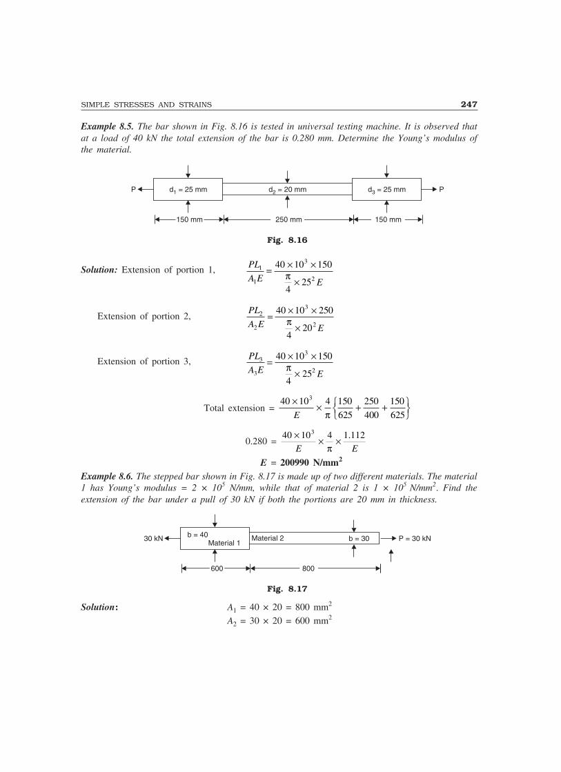
SIMPLE STRESSES AND STRAINS 247
Example 8.5. The bar shown in Fig. 8.16 is tested in universal testing machine. It is observed thatat a load of 40 kN the total extension of the bar is 0.280 mm. Determine the Young’s modulus ofthe material.
PP d = 25 mm1 d = 25 mm3d = 20 mm2
250 mm250 mm150 mm150 mm 150 mm150 mm
Fig. 8.16
Solution: Extension of portion 1, PL
A E E
1
1
3
2
40 10 150
425
= × ×
×π
Extension of portion 2,PL
A E E
2
2
3
2
40 10 250
420
= × ×
×π
Extension of portion 3, PL
A E E
3
3
3
2
40 10 150
425
= × ×
×π
Total extension = 40 10 4 150
625
250
400
150
625
3×× + +���
���E π
0.280 = 40 10 43× × ×
E Eπ1.112
E = 200990 N/mm2
Example 8.6. The stepped bar shown in Fig. 8.17 is made up of two different materials. The material1 has Young’s modulus = 2 × 10⁵ N/mm, while that of material 2 is 1 × 10⁵ N/mm2. Find theextension of the bar under a pull of 30 kN if both the portions are 20 mm in thickness.
P = 30 kN30 kN b = 40 b = 30
800800600600
Material 1Material 2
Fig. 8.17
Solution: A1 = 40 × 20 = 800 mm2
A2 = 30 × 20 = 600 mm2
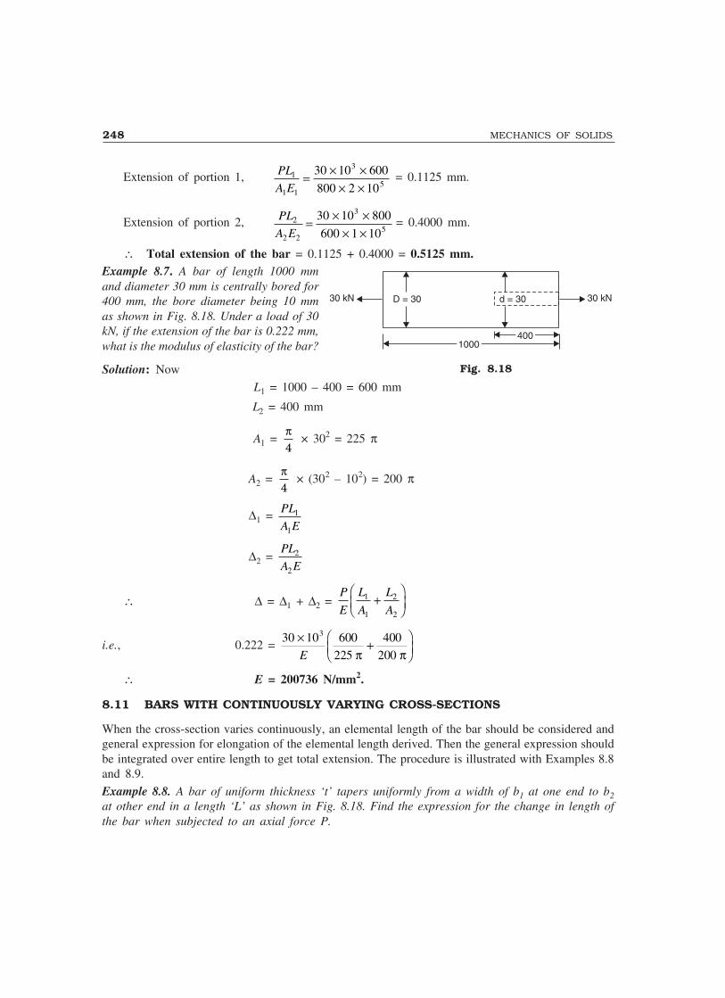
248 MECHANICS OF SOLIDS
Extension of portion 1, PL
A E1
1 1
3
5
30 10 600
800 2 10= × ×
× × = 0.1125 mm.
Extension of portion 2, PL
A E2
2 2
3
5
30 10 800
600 1 10= × ×
× × = 0.4000 mm.
∴ Total extension of the bar = 0.1125 + 0.4000 = 0.5125 mm.Example 8.7. A bar of length 1000 mmand diameter 30 mm is centrally bored for400 mm, the bore diameter being 10 mmas shown in Fig. 8.18. Under a load of 30kN, if the extension of the bar is 0.222 mm,what is the modulus of elasticity of the bar?
Solution: Now
L1 = 1000 – 400 = 600 mm
L2 = 400 mm
A1 = π4
× 302 = 225 π
A2 = π4
× (302 – 102) = 200 π
∆1 = PL
A E1
1
∆2 = PL
A E2
2
∴ ∆ = ∆1 + ∆2 = P
E
L
A
L
A1
1
2
2
+�
�
��
i.e., 0.222 = 30 10 600
225
400
200
3× +��
��E π π
∴ E = 200736 N/mm2.
8.11 BARS WITH CONTINUOUSLY VARYING CROSS-SECTIONS
When the cross-section varies continuously, an elemental length of the bar should be considered andgeneral expression for elongation of the elemental length derived. Then the general expression shouldbe integrated over entire length to get total extension. The procedure is illustrated with Examples 8.8and 8.9.
Example 8.8. A bar of uniform thickness ‘t’ tapers uniformly from a width of b1 at one end to b2at other end in a length ‘L’ as shown in Fig. 8.18. Find the expression for the change in length ofthe bar when subjected to an axial force P.
Fig. 8.18
30 kN 30 kND = 30 d = 30
40040010001000

SIMPLE STRESSES AND STRAINS 249
b1b1P P
dxxx
LL
bb bb
t
Cross-section
b2
Fig. 8.19
Solution: Consider an elemental length dx at a distance x from larger end. Rate of change of breadth
is b b
L1 2−
.
Hence, width at section x is b = b1 – b b
L1 2−
x = b1 – kx
where k = b b
L1 2−
∴ Cross-section area of the element = A = t(b1 – kx)Since force acting at all sections is P only,
Extension of element = Pdx
AE[where length = dx]
= Pdx
b kx tE( )1 −
Total extension of the bar = 0 1 0 1
L LPdx
b kx tE
P
tE
dx
b kx −=
−( ) ( )
= P
tE kb kx
L1
1
0−����
−�
��
�
��log ( )
= P
tEkb
b b
Lx
L
− −−�
��
���
���
log 11 2
0
= P
tEk[– log b2 + log b1] =
P
tEk log
b
b1
2
= PL
tE(b b )log
bb1 2
1
2−. ...(8.16)
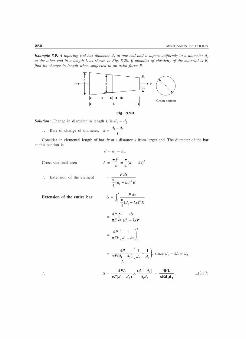
250 MECHANICS OF SOLIDS
Example 8.9. A tapering rod has diameter d1 at one end and it tapers uniformly to a diameter d2at the other end in a length L as shown in Fig. 8.20. If modulus of elasticity of the material is E,find its change in length when subjected to an axial force P.
Cross-section
d1d1P P
dxxx
LL
bbd2
d
Fig. 8.20
Solution: Change in diameter in length L is d1 – d2
∴ Rate of change of diameter, k = d d
L1 2−
Consider an elemental length of bar dx at a distance x from larger end. The diameter of the barat this section is
d = d1 – kx.
Cross-sectional area A = π πd2
4 4= (d1 – kx)2
∴ Extension of the element = P dx
d kx Eπ4 1
2( )−
Extension of the entire bar ∆ = 0
12
4
L P dx
d kx E
−π( )
= 4
0 12
P
E
dx
d kx
L
π −( )
= 4 1
1 0
P
Ek d kx
L
π −�
�
��
= 4 1 1
1 2 2 1
PE d d
Ld dπ ( )− −�
�
��, since d1 – kL = d2
∴ ∆ = 4
1 2
1 2
1 2
PL
E d d
d d
d dπ ( )
( )
−×
− =
4PLEd d1 2π
. ...(8.17)

SIMPLE STRESSES AND STRAINS 251
Note: For bar of uniform diameter extension is PL
dE
π 2
4
and for tapering rod it is PL
d d Eπ4 1 2
.
Thus the change is, instead of d2 for uniform bar, d1 d2 term appears if the bar tapers uniformly.
Example 8.10. A steel flat of thickness 10 mm tapers uniformly from 60 mm at one end to 40 mmat other end in a length of 600 mm. If the bar is subjected to a load of 80 kN, find its extension.Take E = 2 × 10⁵ MPa. What is the percentage error if average area is used for calculatingextension?
Solution: Now, t = 10 mm b1 = 60 mm b2 = 40 mm L = 600 mm P = 80 kN = 80000 N
Now, 1 MPa = 1 N/mm2
Hence E = 2 × 10⁵ N/mm2
Extension of the tapering bar of rectangular section
∆∆∆∆∆ = PL
tE b b( )1 2− log
b
b1
2
= 80000 600
10 2 10 60 405
×× × −( )
log 60
40
= 0.4865 mmIf averages cross-section is considered instead of tapering cross-section, extension is given by
∆ = PL
A Eav
Now Aav = 60 10 40 10
2
× + × = 500 mm2
∆ = 80000 600
500 2 105
×× ×
= 0.480 mm
∴ Percentage error = 0 0
0
.4865 .48
.4865
− × 100
= 1.348Example 8.11. A 2.0 m long steel bar is having uniform diameter of 40 mm for a length of 1 m andin the next 0.5 m its diameter gradually reduces from 40 mm to 20 mm as shown in Fig. 8.21.Determine the elongation of this bar when subjected to an axial tensile load of 200 kN. GivenE = 200 GN/m2.
20
200 kN
15001500 500500
200 kN4040
Fig. 8.21
252 MECHANICS OF SOLIDS
Solution: Now, P = 200 × 103 N
E = 200 GN/m2 = 200 10
1000
9
2
×( )
N/mm2
= 200 × 1000 N/mm2
= 2 × 10⁵ N/mm2
Extensions of uniform portion and tapering portion are worked out separately and then added toget extension of the given bar.
Extension of uniform portion
∆1 = PL
AE =
200 10 1500
440 2 10
3
2 5
× ×
× × ×π = 1.194 mm.
Extension of tapering portion
∆2 = 4
1 2
PL
E d dπ = 4 200 10 500
2 10 60 40
3
5
× × ×× × × ×π
= 0.265 mm
Total extension = ∆1 + ∆2 = 1.194 + 0.265 = 1.459 mmExample 8.12. The extension of a bar uniformly tapering from a diameter of d + a tod – a in a length L is calculated by treating it as a bar of uniform cross-section of average diameterd. What is the percentage error?
Solution: Actual extension under load
P = 4
1 2
PL
d d Eπ =
4PL
d a d a Eπ( )( )+ −
= 4
2 2
PL
E d aπ ( )−If it is treated as a bar of uniform diameter ‘d’, erroneous extension calculated
= PL
d Eπ4
2× =
42
PL
d Eπ
∴ Percentage error =
4 4
4100
2 2 2
2 2
PL
E d a
PL
EdPL
E d a
π π
π
( )
( )
−−
−
×
=
1 1
1
2 2 2
2 2
( )
( )
d a d
d a
−−
−
× 100
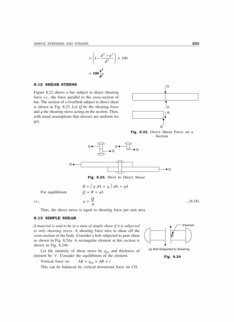
SIMPLE STRESSES AND STRAINS 253
= 12 2
2−−�
�
��d a
d × 100
= 100a
d
2
2
8.12 SHEAR STRESS
Figure 8.22 shows a bar subject to direct shearingforce i.e., the force parallel to the cross-section ofbar. The section of a rivet/bolt subject to direct shearis shown in Fig. 8.23. Let Q be the shearing forceand q the shearing stress acting on the section. Then,with usual assumptions that stresses are uniform weget,
Q
Q
RQ
Q
Q
Fig. 8.23. Rivet in Direct Shear
R = ∫ q dA = q ∫ dA = qA
For equilibrium Q = R = qA
i.e., q = Q
A...(8.18)
Thus, the direct stress is equal to shearing force per unit area.
8.13 SIMPLE SHEAR
A material is said to be in a state of simple shear if it is subjectedto only shearing stress. A shearing force tries to shear off thecross-section of the body. Consider a bolt subjected to pure shearas shown in Fig. 8.24a. A rectangular element at this section isshown in Fig. 8.24b.
Let the intensity of shear stress be qab and thickness ofelement be ‘t’. Consider the equilibrium of the element.
Vertical force on AB = qab × AB × t
This can be balanced by vertical downward force on CD.
Q
P
R
Q
Fig. 8.22. Direct Shear Force on aSection
Fig. 8.24
Element
(a) Bolt Subjected to Shearing
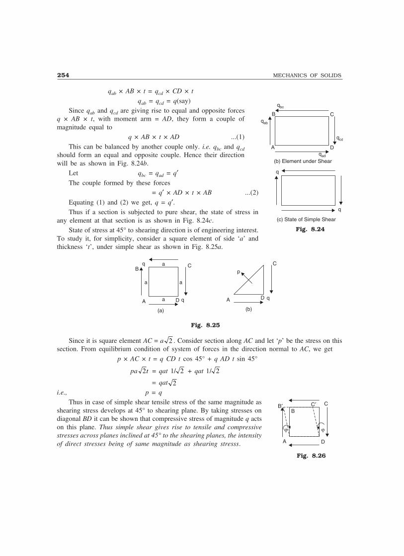
254 MECHANICS OF SOLIDS
qab × AB × t = qcd × CD × t
qab = qcd = q(say)Since qab and qcd are giving rise to equal and opposite forces
q × AB × t, with moment arm = AD, they form a couple ofmagnitude equal to
q × AB × t × AD ...(1)
This can be balanced by another couple only. i.e. qbc and qcdshould form an equal and opposite couple. Hence their directionwill be as shown in Fig. 8.24b.
Let qbc = qad = q′The couple formed by these forces
= q′ × AD × t × AB ...(2)
Equating (1) and (2) we get, q = q′.Thus if a section is subjected to pure shear, the state of stress in
any element at that section is as shown in Fig. 8.24c.State of stress at 45° to shearing direction is of engineering interest.
To study it, for simplicity, consider a square element of side ‘a’ andthickness ‘t’, under simple shear as shown in Fig. 8.25a.
C
aa
a
a D qA
qB
(a)
p
C
D qA
(b)
Fig. 8.25
Since it is square element AC = a 2 . Consider section along AC and let ‘p’ be the stress on thissection. From equilibrium condition of system of forces in the direction normal to AC, we get
p × AC × t = q CD t cos 45° + q AD t sin 45°
pa 2t = qat 1/ 2 + qat 1/ 2
= qat 2i.e., p = q
Thus in case of simple shear tensile stress of the same magnitude asshearing stress develops at 45° to shearing plane. By taking stresses ondiagonal BD it can be shown that compressive stress of magnitude q actson this plane. Thus simple shear gives rise to tensile and compressivestresses across planes inclined at 45° to the shearing planes, the intensityof direct stresses being of same magnitude as shearing stresss.
C
D
qcd
qab
qbc
B
Aqad
(b) Element under Shear
q
q
(c) State of Simple Shear
Fig. 8.24
C
DA
��
C�B�B
Fig. 8.26
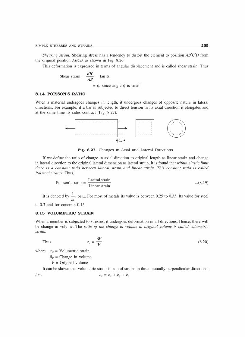
SIMPLE STRESSES AND STRAINS 255
Shearing strain. Shearing stress has a tendency to distort the element to position AB′C′D fromthe original position ABCD as shown in Fig. 8.26.
This deformation is expressed in terms of angular displacement and is called shear strain. Thus
Shear strain = BB
AB
′ = tan φ
= φ, since angle φ is small
8.14 POISSON’S RATIO
When a material undergoes changes in length, it undergoes changes of opposite nature in lateraldirections. For example, if a bar is subjected to direct tension in its axial direction it elongates andat the same time its sides contract (Fig. 8.27).
�L
Fig. 8.27. Changes in Axial and Lateral Directions
If we define the ratio of change in axial direction to original length as linear strain and changein lateral direction to the original lateral dimension as lateral strain, it is found that within elastic limitthere is a constant ratio between lateral strain and linear strain. This constant ratio is calledPoisson’s ratio. Thus,
Poisson’s ratio = Lateral strain
Linear strain...(8.19)
It is denoted by 1
m, or µ. For most of metals its value is between 0.25 to 0.33. Its value for steel
is 0.3 and for concrete 0.15.
8.15 VOLUMETRIC STRAIN
When a member is subjected to stresses, it undergoes deformation in all directions. Hence, there willbe change in volume. The ratio of the change in volume to original volume is called volumetricstrain.
Thus ev = δV
V...(8.20)
where eV = Volumetric strain
δV = Change in volume V = Original volume
It can be shown that volumetric strain is sum of strains in three mutually perpendicular directions.i.e., ev = ex + ey + ez

256 MECHANICS OF SOLIDS
For example consider a bar of length L, breadth b and depth d as shown in Fig. 8.28.
d
bbLL
zy
x
Fig. 8.28
Now, V = Lbd
Since volume is function of L, b and d.
δV = δL bd + L δb d + Lb δd
δV
V =
δv
Lbd
eV = δ δ δL
L
b
b
d
d+ +
eV = ex + ey + ez
Now, consider a circular rod of length L and diameter ‘d’ as shown in Fig. 8.29.
zy
x
LL
dd
Fig. 8.29
Volume of the bar V = π4
d2L
∴ δV = π4
2dδd L + π4
d2 δL (since v is function of d and L).
∴δ
πV
d L4
2 = 2
δd
d +
δL
L
eV = ex + ey + ez; since ey = ez = δd
d
In general for any shape volumetric strain may be taken as sum of strains in three mutuallyperpendicular directions.
8.16 ELASTIC CONSTANTS
Modulus of elasticity, modulus of rigidity and bulk modulus are the three elastic constants. Modulusof elasticity (Young’s Modulus) ‘E’ has been already defined as the ratio of linear stress to linearstrain within elastic limit. Rigidity modulus and Bulk modulus are defined in this article.

SIMPLE STRESSES AND STRAINS 257
Modulus of Rigidity: It is defined as the ratio of shearing stress to shearing strain within elasticlimit and is usually denoted by letter G or N. Thus
G = q
φ...(8.21)
where G = Modulus of rigidity q = Shearing stress
and φ = Shearing strainBulk Modulus: When a body is subjected to identical stresses p in three mutually perpendicular
directions, (Fig. 8.30), the body undergoes uniform changes in three directions without undergoingdistortion of shape. The ratio of change in volume to original volume has been defined as volumetricstrain (ev). Then the bulk modulus, K is defined as
K = p
ev
where p = identical pressure in three mutually perpendicular directions
ev = ∆v
v, Volumetric strain
∆v = Change in volume v = Original volume
Thus bulk modulus may be defined as the ratio of identical pressure ‘p’ acting in three mutuallyperpendicular directions to corresponding volumetric strain.
p
pp
p
p p
p
p
p
p
p
p
(a) (b)
Fig. 8.30
Figure 8.30 shows a body subjected to identical compressive pressure ‘p’ in three mutuallyperpendicular directions. Since hydrostatic pressure, the pressure exerted by a liquid on a body withinit, has this nature of stress, such a pressure ‘p’ is called as hydrostatic pressure.
8.17 RELATIONSHIP BETWEEN MODULUS OF ELASTICITYAND MODULUS OF RIGIDITY
Consider a square element ABCD of sides ‘a’ subjected to pure shear ‘q’as shown in Fig. 8.31. AEC′D shown is the deformed shape due to shearq. Drop perpendicular BF to diagonal DE. Let φ be the shear strain andG modulus of rigidity.
Aj
C¢ C
aaq
Daa
qqBE
F¢q
Fig. 8.31
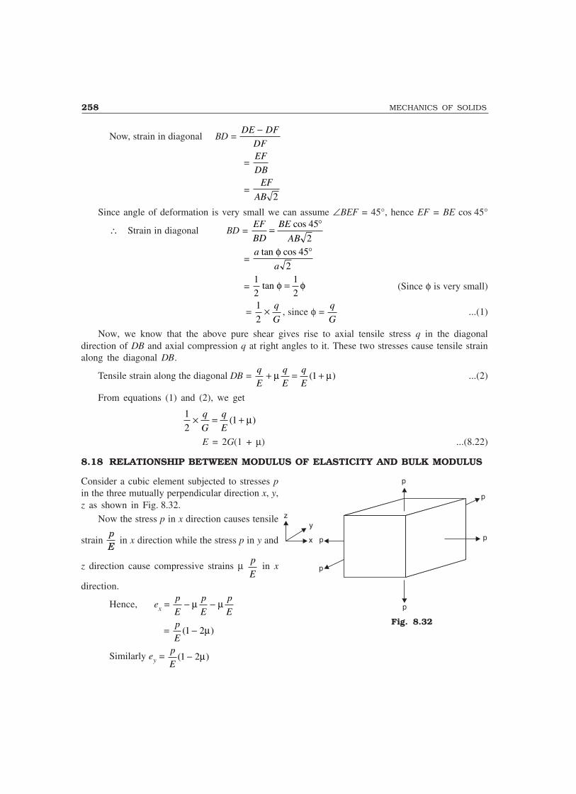
258 MECHANICS OF SOLIDS
Now, strain in diagonal BD = DE DF
DF
−
= EF
DB
= EF
AB 2
Since angle of deformation is very small we can assume ∠BEF = 45°, hence EF = BE cos 45°
∴ Strain in diagonal BD = EF
BD
BE
AB= °cos 45
2
= a
a
tan cosφ 45
2
°
= 1
2
1
2tan φ φ= (Since φ is very small)
= 1
2× q
G, since φ =
q
G...(1)
Now, we know that the above pure shear gives rise to axial tensile stress q in the diagonaldirection of DB and axial compression q at right angles to it. These two stresses cause tensile strainalong the diagonal DB.
Tensile strain along the diagonal DB = q
E
q
E
q
E+ = +µ µ( )1 ...(2)
From equations (1) and (2), we get
1
21× = +q
G
q
E( )µ
E = 2G(1 + µ) ...(8.22)
8.18 RELATIONSHIP BETWEEN MODULUS OF ELASTICITY AND BULK MODULUS
Consider a cubic element subjected to stresses pin the three mutually perpendicular direction x, y,z as shown in Fig. 8.32.
Now the stress p in x direction causes tensile
strain pE
in x direction while the stress p in y and
z direction cause compressive strains µ p
E in x
direction.
Hence, ex = p
E
p
E
p
E− −µ µ
= p
E( )1 2− µ
Similarly ey = p
E( )1 2− µ
Fig. 8.32
zy
x p
p
p
p
p
p

SIMPLE STRESSES AND STRAINS 259
ez = p
E( )1 2− µ ...(1)
∴ Volumetric strain ev = ex + ey + ez = 3
1 2p
E( )− µ
From definition, bulk modulus K is given by
K = p
e
pp
Ev
= −3 1 2( )µ
or E = 3K(1 – µ) ...(2)
Relationship between EGK:
We know E = 2G(1 + µ) ...(a)
and E = 3K(1 – 2µ) ...(b)
By eliminating µ between the above two equations we can get the relationship between E, G,K, free from the term µ.
From equation (a) µ = E
G21−
Substituting it in equation (b), we get
E = 3 1 22
1KE
G− −��
��
���
�
= 3 1 2KE
G− +�
���
= 3 3KE
G−�
���
= 9K – 3KE
G
∴ EK
G1
3+��
�� = 9K
or EG K
G
+��
��
3 = 9K ...(c)
or E = 9
3
KG
G K+...(8.23a)
Equation (c) may be expressed as
9 3
E
G K
KG= +
i.e.,9 3 1
E G K= + ...(8.23b)
Example 8.13. A bar of 25 mm diameter is tested in tension. It is observed that when a load of 60kN is applied, the extension measured over a guage length of 200 mm is 0.12 mm and contractionin diameter is 0.0045 mm. Find Poisson’s ratio and elastic constants E, G, K.
Solution: Now, P = 60 kN = 60000 N
Area A = π4
× 252 = 156.25π mm2
Guage length L = 200 mm
260 MECHANICS OF SOLIDS
∆ = 0.12 mm
∆d = 0.0045 mm
Linear strain = ∆L
= 0 12
200
. = 0.0006
Lateral strain = ∆d
d= 0 0045
25
. = 0.00018
∴ Poisson’s ratio = Lateral strain
Linear strain
0.00018
0.0006=
µµµµµ = 0.3
Now, ∆ = PL
AE
0.12 = 60000 200
156 25
××. π E
or E = 203718.3 N/mm2
Using the relation E = 2G(1 + µ)
We get G = E
2 1
203718 3
2 1 0 3( )
.
( . )+=
+µ = 78353.2 N/mm2
From the relation, E = 3K(1 – 2µ), we get
K = E
3 1 2
203718 3
3 1 2 0 3( )
.
( . )−=
− ×µ = 169765.25 N/mm2
Example 8.14. A circular rod of 25 mm diameter and 500 mm long is subjected to a tensile forceof 60 kN. Determine modulus of rigidity, bulk modulus and change in volume if Poisson’s ratio =0.3 and Young’s modulus E = 2 × 10⁵ N/mm2.
Solution: From the relationship
E = 2G(1 + µ) = 3k(1 – 2µ)
We get, G = E
2 1
2 10
2 1 0 3
5
( ) ( . )+= ×
+µ = 0.7692 × 10⁵ N/mm2
and K = E
3 1 22 10
3 1 2 0 3
5
( ) ( . )+= ×
− ×µ = 1.667 × 10⁵ N/mm2
Longitudinal stress = P
A= ×
×
60 10
425
3
2π = 122.23 N/mm2
Linear strain = Stress
E=
× 5122 23
2 10
. = 61.115 × 10⁻⁵
Lateral strain = ey = – µex and ez = – µex
Volumetric strain ev = ex + ey + ez
= ex(1 – 2µ)
= 61.115 × 10⁻⁵ (1 – 2 × 0.3)= 24.446 × 10⁻⁵
but Change in volume
v = ev
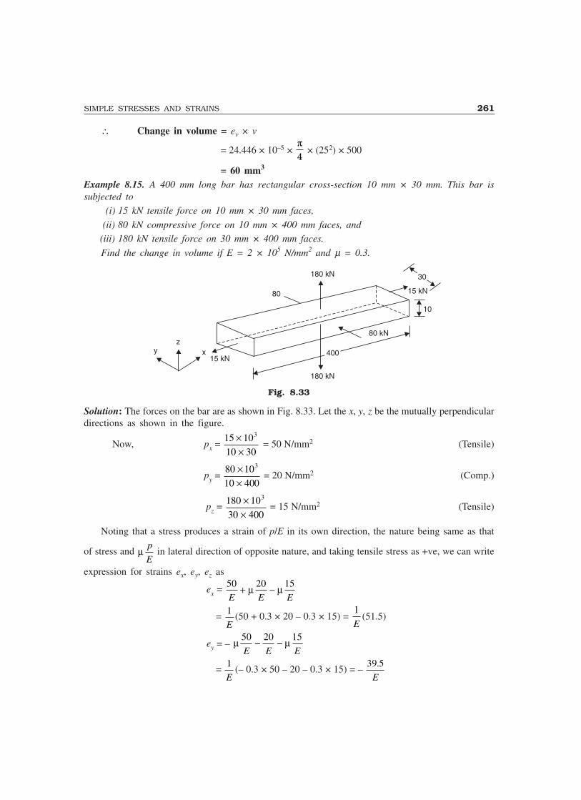
SIMPLE STRESSES AND STRAINS 261
∴ Change in volume = ev × v
= 24.446 × 10⁻⁵ × π4
× (252) × 500
= 60 mm3
Example 8.15. A 400 mm long bar has rectangular cross-section 10 mm × 30 mm. This bar issubjected to
(i) 15 kN tensile force on 10 mm × 30 mm faces,
(ii) 80 kN compressive force on 10 mm × 400 mm faces, and
(iii) 180 kN tensile force on 30 mm × 400 mm faces.
Find the change in volume if E = 2 × 10⁵ N/mm2 and µ = 0.3.
400400
8080
180 kN180 kN 3030
15 kN15 kN
1010
80 kN80 kN
180 kN180 kN
15 kN15 kNy
zx
Fig. 8.33
Solution: The forces on the bar are as shown in Fig. 8.33. Let the x, y, z be the mutually perpendiculardirections as shown in the figure.
Now, px = 15 10
10 30
3××
= 50 N/mm2 (Tensile)
py = 80 10
10 400
3××
= 20 N/mm2 (Comp.)
pz = 180 10
30 400
3××
= 15 N/mm2 (Tensile)
Noting that a stress produces a strain of p/E in its own direction, the nature being same as that
of stress and µ p
E in lateral direction of opposite nature, and taking tensile stress as +ve, we can write
expression for strains ex, ey, ez as
ex = 50 20 15
E E E+ −µ µ
= 1
E(50 + 0.3 × 20 – 0.3 × 15) =
1
E(51.5)
ey = – µ µ50 20 15
E E E− −
= 1
E(– 0.3 × 50 – 20 – 0.3 × 15) = –
39 5.
E

262 MECHANICS OF SOLIDS
ez = – µ µ50 20 15
E E E+ +
= 1
E(– 0.3 × 50 + 20 × 0.3 + 15) =
6
E
Volumetric strain: ev = ex + ey + ez
= 1
E(51.5 – 39.5 + 6) =
18
E
ButChange in volume
Volume = ev
∴ Change in volume = ev × Volume
= 18
2 105× × 10 × 30 × 400
= 10.8 mm3
Example 8.16. A bar of rectangular section shown in Fig. 8.34 is subjected to stresses px, py andpz in x, y and z directions respectively. Show that if sum of these stresses is zero, there is no changein volume of the bar.
yz
x
px
pzpz
pypy
px
pzpz
pypy
Fig. 8.34
Solution: A stress p produces strain of magnitude p/E in its direction and a strain µ p
E of opposite
nature at right angles to its direction.
Hence ex = p
E
p
E
p
Ex y z− −µ µ
ey = – µ µp
E
p
E
p
Ex y z+ −
ez = – µ µp
E
p
E
p
Ex y z− +

SIMPLE STRESSES AND STRAINS 263
Now, ev = ex + ey + ez
= p
E
p
E
p
Ex y z( ) ( ) ( )1 2 1 2 1 2− + − + −µ µ µ
i.e.,dV
V
p p p
Ex y z=
+ +( )(1 – 2µ)
Hence if px + py + pz = 0
ev = dV
V = 0
∴ dV = 0i.e., there is no volumetric change, if px + py + pz = 0.
Example 8.17. In a laboratory, tensile test is conducted and Young’s modulus of the material isfound to be 2.1 × 10⁵ N/mm2. On the same material torsion test is conducted and modulus of rigidityis found to be 0.78 × 10⁵ N/mm2. Determine Poisson’s Ratio and bulk modulus of the material.
[Note: This is usual way of finding material properties in the laboratory].
Solution: E = 2.1 × 10⁵ N/mm2
G = 0.78 × 10⁵ N/mm2
Using relation E = 2G(1 + µ)
we get 2.1 × 105 = 2 × 0.78 × 105 (1 + µ)
1.346 = 1 + µor µµµµµ = 0.346
From relation E = 3K(1 – 2µ)
we get 2.1 × 105 = 3 × K(1 – 2 × 0.346)
K = 2.275 × 10⁵ N/mm2
Example 8.18. A material has modulus of rigidity equal to 0.4 × 10⁵ N/mm2 and bulk modulus equalto 0.8 × 10⁵ N/mm2. Find its Young’s Modulus and Poisson’s Ratio.
Solution: G = 0.4 × 10⁵ N/mm2
K = 0.8 × 10⁵ N/mm2
Using the relation E = 9
3
GK
K G+
E = 9 0 10 0 8 10
3 0 8 10 0 10
5 5
5 5
× × × ×× × + ×
.4 .
. .4
E = 1.0286 × 10⁵ N
From the relation E = 2G(1 + µ)
we get 1.0286 × 105 = 2 × 0.4 × 105(1 + µ)
1.2857 = 1 + µor µ µ µ µ µ = 0.2857
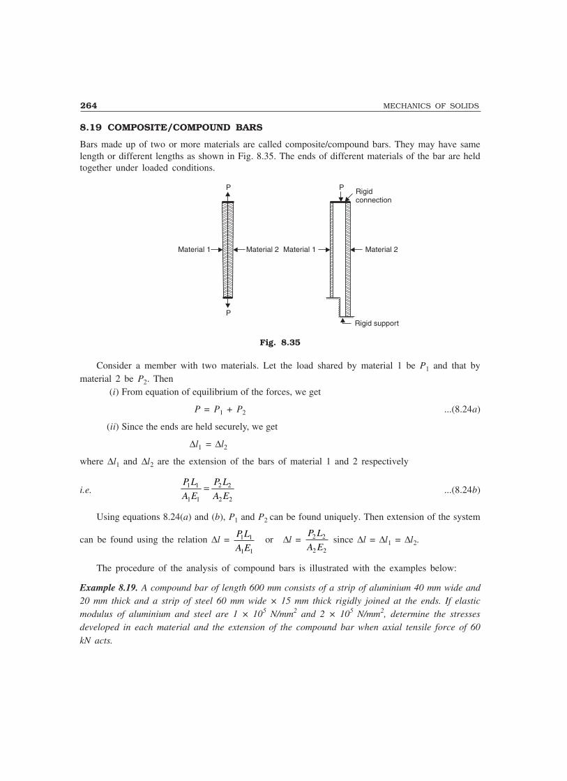
264 MECHANICS OF SOLIDS
8.19 COMPOSITE/COMPOUND BARS
Bars made up of two or more materials are called composite/compound bars. They may have samelength or different lengths as shown in Fig. 8.35. The ends of different materials of the bar are heldtogether under loaded conditions.
P P Rigidconnection
Material 2Material 1
Rigid supportP
Material 2Material 1
Fig. 8.35
Consider a member with two materials. Let the load shared by material 1 be P1 and that bymaterial 2 be P2. Then
(i) From equation of equilibrium of the forces, we get
P = P1 + P2 ...(8.24a)
(ii) Since the ends are held securely, we get
∆l1 = ∆l2
where ∆l1 and ∆l2 are the extension of the bars of material 1 and 2 respectively
i.e.P L
A E
P L
A E1 1
1 1
2 2
2 2
= ...(8.24b)
Using equations 8.24(a) and (b), P1 and P2 can be found uniquely. Then extension of the system
can be found using the relation ∆l = P L
A E1 1
1 1
or ∆l = P L
A E2 2
2 2
since ∆l = ∆l1 = ∆l2.
The procedure of the analysis of compound bars is illustrated with the examples below:
Example 8.19. A compound bar of length 600 mm consists of a strip of aluminium 40 mm wide and20 mm thick and a strip of steel 60 mm wide × 15 mm thick rigidly joined at the ends. If elasticmodulus of aluminium and steel are 1 × 10⁵ N/mm2 and 2 × 10⁵ N/mm2, determine the stressesdeveloped in each material and the extension of the compound bar when axial tensile force of 60kN acts.

SIMPLE STRESSES AND STRAINS 265
Solution: The compound bar is shown in the figure 8.36.
Data available is L = 600 mm P = 60 kN = 60 × 1000 N
Aa = 40 × 20 = 800 mm2
As = 60 × 15 = 900 mm2
Ea = 1 × 10⁵ N/mm2, Es = 2 × 10⁵ N/mm2.Let the load shared by aluminium strip be Pa and that shared by
steel be Ps. Then from equilibrium conditionPa + Ps = 60 × 1000 ...(1)
From compatibility condition, we have ∆a = ∆s
P L
A E
P L
A Ea
a a
s
s s
=
i.e. P Pa s×
× ×=
×× ×
600
800 1 10
600
900 2 105 5
Ps = 2.25 Pa ...(2)Substituting it in eqn. (1), we get
Pa + 2.25 Pa = 60 × 1000
i.e. Pa = 18462 N.
∴ Ps = 2.25 × 18462 = 41538 N.
∴ Stress in aluminium strip = P
Aa
a
= 18462
800
= 23.08 N/mm2
Stress in steel strip = P
As
s
= 41538
900 = 46.15 N/mm2
Extension of the compound bar = P L
A Ea
a a
= ×× ×
18462 600
800 1 105
∆l = 0.138 mm.
Example 8.20. A compound bar consists of a circular rod of steel of 25mm diameter rigidly fixed into a copper tube of internal diameter 25 mmand external diameter 40 mm as shown in Fig. 8.37. If the compound baris subjected to a load of 120 kN, find the stresses developed in the twomaterials.
Take Es = 2 ×10⁵ N/mm2
and Ec = 1.2 × 10⁵ N/mm2.
Fig. 8.36
Copper tube
Steel rod
Fig. 8.37
600 mm600 mmSteel
Aluminium
60 kN
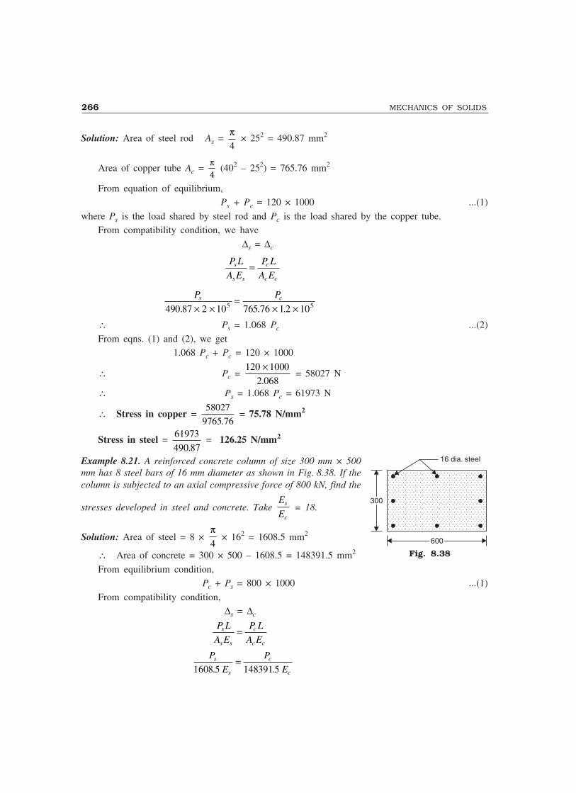
266 MECHANICS OF SOLIDS
Solution: Area of steel rod As = π4
× 252 = 490.87 mm2
Area of copper tube Ac = π4
(402 – 252) = 765.76 mm2
From equation of equilibrium, Ps + Pc = 120 × 1000 ...(1)
where Ps is the load shared by steel rod and Pc is the load shared by the copper tube.From compatibility condition, we have
∆s = ∆c
P L
A E
P L
A Es
s s
c
c c
=
P Ps c
490 87 2 10 765 76 1 2 105 5. . .× ×=
× ×∴ Ps = 1.068 Pc ...(2)
From eqns. (1) and (2), we get1.068 Pc + Pc = 120 × 1000
∴ Pc = 120 1000
2 068
×.
= 58027 N
∴ Ps = 1.068 Pc = 61973 N
∴ Stress in copper = 58027
9765 76. = 75.78 N/mm2
Stress in steel = 61973
490 87. = 126.25 N/mm2
Example 8.21. A reinforced concrete column of size 300 mm × 500mm has 8 steel bars of 16 mm diameter as shown in Fig. 8.38. If thecolumn is subjected to an axial compressive force of 800 kN, find the
stresses developed in steel and concrete. Take E
Es
c = 18.
Solution: Area of steel = 8 × π4
× 162 = 1608.5 mm2
∴ Area of concrete = 300 × 500 – 1608.5 = 148391.5 mm2
From equilibrium condition,Pc + Ps = 800 × 1000 ...(1)
From compatibility condition, ∆s = ∆c
P L
A E
P L
A Es
s s
c
c c
=
P
E
P
Es
s
c
c1608 5 148391 5. .=
Fig. 8.38
16 dia. steel
600600
300300
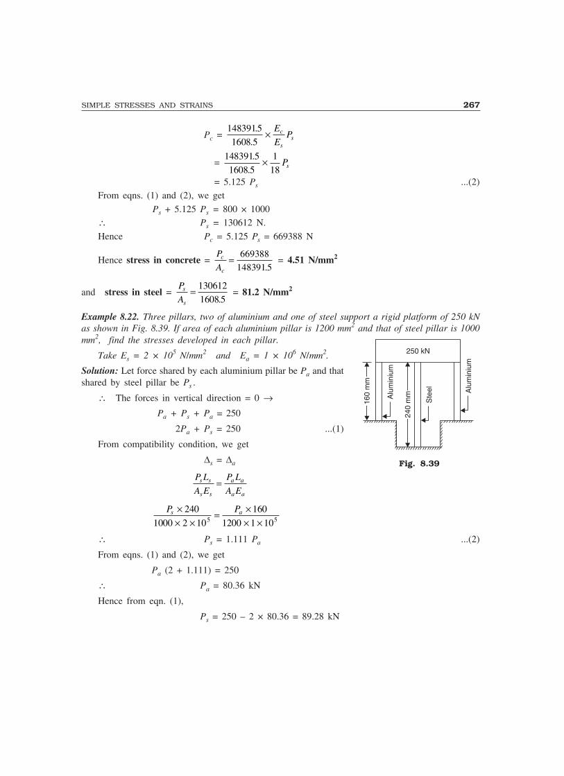
SIMPLE STRESSES AND STRAINS 267
Pc = 1483915
1608 5
.
.× E
EPc
ss
= 1483915
1608 5
1
18
.
.× Ps
= 5.125 Ps ...(2)From eqns. (1) and (2), we get
Ps + 5.125 Ps = 800 × 1000∴ Ps = 130612 N.
Hence Pc = 5.125 Ps = 669388 N
Hence stress in concrete = P
Ac
c
= 669388
148391 5. = 4.51 N/mm2
and stress in steel = P
As
s
= 130612
1608 5. = 81.2 N/mm2
Example 8.22. Three pillars, two of aluminium and one of steel support a rigid platform of 250 kNas shown in Fig. 8.39. If area of each aluminium pillar is 1200 mm2 and that of steel pillar is 1000mm2, find the stresses developed in each pillar.
Take Es = 2 × 10⁵ N/mm2 and Ea = 1 × 10⁶ N/mm2.
Solution: Let force shared by each aluminium pillar be Pa and thatshared by steel pillar be Ps .
∴ The forces in vertical direction = 0 →Pa + Ps + Pa = 250
2Pa + Ps = 250 ...(1)
From compatibility condition, we get
∆s = ∆a
P L
A E
P L
A Es s
s s
a a
a a
=
P Ps a×× ×
= ×× ×
240
1000 2 10
160
1200 1 105 5
∴ Ps = 1.111 Pa ...(2)
From eqns. (1) and (2), we get
Pa (2 + 1.111) = 250
∴ Pa = 80.36 kN
Hence from eqn. (1),
Ps = 250 – 2 × 80.36 = 89.28 kN
Fig. 8.39
250 kN
Ste
el Alu
min
ium
Alu
min
ium
240
mm
160
mm

268 MECHANICS OF SOLIDS
∴ Stresses developed are
σs = P
As
s
= ×89 28 1000
1000
. = 89.28 N/mm2
σa = 80 36 1000
1200
. × = 66.97 N/mm2
Example 8.23. A steel bolt of 20 mm diameter passes centrally through a copper tube of internal
diameter 28 mm and external diameter 40 mm. The length of whole assembly is 600 mm. After tight
fitting of the assembly, the nut is over tightened by quarter of a turn. What are the stresses introduced
in the bolt and tube, if pitch of nut is 2 mm? Take Es = 2 × 10⁵ N/mm2 and Ec = 1.2 × 10⁵ N/mm2.
Copper tube
Steel bolt
600 mm
Copper tube
Steel bolt
(a)(b)
Fig. 8.40
Solution: Figure 8.40 shows the assembly. Let the force shared by bolt be Ps and that by tube bePc. Since there is no external force, static equilibrium condition gives
Ps + Pc = 0 or Ps = – Pc
i.e., the two forces are equal in magnitude but opposite in nature. Obviously bolt is in tension andtube is in compression.
Let the magnitude of force be P. Due to quarter turn of the nut, the nut advances by 1
4 × pitch
= 1
4 × 2 = 0.5 mm.
[Note. Pitch means advancement of nut in one full turn]
During this process bolt is extended and copper tube is shortened due to force P developed. Let∆s be extension of bolt and ∆c shortening of copper tube. Final position of assembly be ∆, then
∆s + ∆c = ∆
i.e.P L
A E
P L
A Es s
s s
c c
c c
+ = 0.5
P P×× × ×
+ ×− × ×
600
4 20 2 10
600
4 40 28 1 2 102 5 2 2 5( / ) ( / ) ( ) .π π = 0.5
P ×× ×
+− ×
�
��
�
��
600
4 105( / )π1
20 2
1
(40 28 ) 1.22 2 2 = 0.5
∴ P = 28816.8 N

SIMPLE STRESSES AND STRAINS 269
∴ ps = P
As
s
=×
28816 8
4 202
.
( / )π = 91.72 N/mm2
pc = P
Ac
c
=−
28816 8
4 40 282 2
.
( / ) ( )π = 44.96 N/mm2
8.20 THERMAL STRESSES
Every material expands when temperature rises and contracts when temperature falls. It is establishedexperimentally that the change in length ∆ is directly proportional to the length of the member L andchange in temperature t. Thus
∆ ∝ tL
= α tL ...(8.25)The constant of proportionality α is called coefficient of thermal expansion and is defined as
change in unit length of material due to unit change in temperature. Table 8.1 shows coefficient ofthermal expansion for some of the commonly used engineering materials:
Table 8.1
Material Coefficient of thermalexpansion
Steel 12 × 10–6/°C
Copper 17.5 × 10⁻⁶/°C
Stainless steel 18 × 10–6/°C
Brass, Bronze 19 × 10–6/°C
Aluminium 23 × 10–6/°C
If the expansion of the member is freely permitted, as shown in Fig. 8.41, no temperaturestresses are induced in the material.
LL
αtLαtL
Fig. 8.41 Free Expansion Permitted
If the free expansion is prevented fully or partially the stresses are induced in the bar, by thesupport forces. Referring to Fig. 8.42,
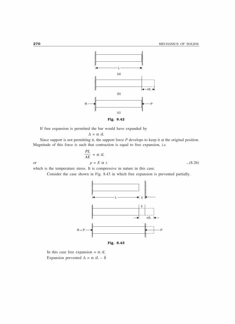
270 MECHANICS OF SOLIDS
LL
αtLαtL
(a)
(b)
(c)
R P
Fig. 8.42
If free expansion is permitted the bar would have expanded by∆ = α tL
Since support is not permitting it, the support force P develops to keep it at the original position.Magnitude of this force is such that contraction is equal to free expansion, i.e.
PL
AE = α tL
or p = E α t. ...(8.26)
which is the temperature stress. It is compressive in nature in this case.Consider the case shown in Fig. 8.43 in which free expansion is prevented partially.
LL
αtL
R = P P
δ
δ
Fig. 8.43
In this case free expansion = α tL
Expansion prevented ∆ = α tL – δ

SIMPLE STRESSES AND STRAINS 271
The expansion is prevented by developing compressive force P at supports
∴PL
AE = ∆ = α tL – δ. ...(8.27)
Example 8.24. A steel rail is 12 m long and is laid at a temperature of 18°C. The maximumtemperature expected is 40°C.
(i) Estimate the minimum gap between two rails to be left so that the temperature stresses donot develop.
(ii) Calculate the temperature stresses developed in the rails, if:(a) No expansion joint is provided.
(b) If a 1.5 mm gap is provided for expansion.
(iii) If the stress developed is 20 N/mm2, what is the gap provided between the rails?
Take E = 2 × 10⁵ N/mm2 and α = 12 × 10–6/°C.
Solution:(i) The free expansion of the rails
= α tL = 12 × 10–6 × (40 – 18) × 12.0 × 1000
= 3.168 mm∴ Provide a minimum gap of 3.168 mm between the rails, so that temperature stresses
do not develop.(ii) (a) If no expansion joint is provided, free expansion prevented is equal to 3.168 mm.
i.e. ∆ = 3.168 mm
∴ PL
AE = 3.168
∴ p = P
A= × ×
×3168 2 10
12 1000
5. = 52.8 N/mm2
(b) If a gap of 1.5 mm is provided, free expansion prevented ∆ = α tL – δ = 3.168 – 1.5 =1.668 mm.
∴ The compressive force developed is given by PL
AE = 1.668
or p = P
A= × ×
×1.668 2 10
12 1000
5
= 27.8 N/mm2
(iii) If the stress developed is 20 N/mm2, then p = P
A = 20
If δ is the gap, ∆ = α tL – δ
∴ PL
AE = 3.168 – δ
i.e. 20 × 12 1000
2 105
××
= 3.168 – δ
∴ δδδδδ = 3.168 – 1.20 = 1.968 mm

272 MECHANICS OF SOLIDS
Example 8.25. The temperature of a steel ring is raised through 150°C in order to fit it on a woodenwheel of 1.2 m diameter. Find the original diameter of the steel ring and also the stresses developedin the ring, when it cools back to normal temperature. Assume Es = 2 × 10⁵ N/mm2 and αs = 12× 10–6/°C.
Solution: Let D be the diameter of ring after heating and ‘d’ be its diameter before heating∴ D = 1.2 m = 1200 mm.
Circumference of ring after heating = πD
Circumference of ring before heating (L) = πd
∴ πD = πd + αs t (πd)D = d + αs t d = (1 + αs t)d
i.e., 1200 = [1 + 12 × 10–6 × 150] d
∴ d = 1197.84 mm.
when it cools expansion prevented∆ = π(D – d) = αstπd = 12 × 10–6 × 150 πd
= 1800 × 10–6 πd
∴PL
AE = 1800 × 10–6 πd
P
A
d
E��
× ×π = 1800 × 10–6 πd
Stress p = P
A = 1800 × 10–6 × 2 × 105 = 360 N/mm2
Example 8.26. The composite bar shown in Fig. 8.44 is rigidly fixed at the ends A and B. Determinethe reaction developed at ends when the temperature is raised by 18°C. Given
Ea = 70 kN/mm2
Es = 200 kN/mm2
αa = 11 × 10–6/°C
αs = 12 × 10–6/°C
Aluminium
1.5 m1.5 m 3.0 m3.0 m
A = 600 mma2
Steel
A = 400 mms2
(a)
(b)
Fig. 8.44

SIMPLE STRESSES AND STRAINS 273
Solution: Free expansion = αa tLa + αstLs
= 11 × 10–6 × 18 × 1500 + 12 × 10–6 × 18 × 3000 = 0.945 mm
Since this is prevented
∆ = 0.945 mm.Ea = 70 kN/mm2 = 70000 N/mm2 ;
Es = 200 kN/mm2 = 200 × 1000 N/mm2
If P is the support reaction,
∆ = PL
A E
PL
A Ea
a a
s
s s
+
i.e. 0.945 = P1500
600 70000
3000
400 200 1000×+
× ×�
��
�
��
0.945 = 73.214 × 10⁻⁶ P
or P = 12907.3 N
Example 8.27. The steel bar AB shown in Fig. 8.45 varies linearly in diameter from 25 mm to 50mm in a length 500 mm. It is held between two unyielding supports at room temperature. What isthe stress induced in the bar, if temperature rises by 25°C? Take Es = 2 × 10⁵ N/mm2 andαs
= 12 × 10–6/°C.
500 mm500 mm
A B
25 m
m
50 mm
Fig. 8.45
Solution: Free expansion of bar = α tL
= 12 × 10–6 × 25 × 500 = 0.15 mm.
This expansion is prevented ∴ ∆ = 0.15 mm.If P is the force developed by supports, then it can cause a contraction of
4 4 500
25 50 2 101 25
PL
d d E
P
π π= × ×
× × × ×Equating it to the contraction prevented, for satisfying the compatibility, we get
4 500
25 50 2 105
P ×× × × ×π
= 0.15

274 MECHANICS OF SOLIDS
∴ P = 58905 N
∴ Corresponding maximum stress = P
Amin
=×
58905
4252π
= 120 N/mm2.
8.21 THERMAL STRESSES IN COMPOUND BARS
When temperature rises the two materials of the compound bar experience different free expansion.Since they are prevented from seperating, the two bars will have common position. This is possibleonly by extension of the bar which has less free expansion and contraction of the bar which has morefree expansion. Thus one bar develops tensile force and another develops the compressive force. Inthis article we are interested to find such stresses.
Consider the compound bar shown in Fig. 8.46(a). Let α1, α2 be coefficient of thermal expansionand E1, E2 be moduli of elasticity of the two materials respectively. If rise in temperature is ‘t’,
Free expansion of bar 1 = α1 tL
Free expansion of bar 2 = α2 tL
Let α1 > α2. Hence the position of the two bars, if the free expansions are permitted are at AAand BB as shown in Fig. 8.46(b)
d tL2
B
B
�2
C
C
P2
�1
A
A
P1
Bar -2
Bar-1
�1tL�1tL
Bar -2
Bar-1
Fig. 8.46
Since the two bars are rigidly connected at the ends, the final position of the end will besomewhere between AA and BB, say at CC. It means Bar–1 will experience compressive force P1
which contracts it by ∆1 and Bar–2 experience tensile force P2 which will expand it by ∆2.
The equilibrium of horizontal forces gives,
P1 = Pc, say P
From the Fig. 8.46 (b), it is clear,
α1 tL – ∆1 = α2 tL + ∆2
∴ ∆1 + ∆2 = α1 tL – α2 tL = (α1 – α2) tL.
If the cross-sectional areas of the bars are A1 and A2, we get
PL
A E
PL
A E1 1 2 2
+ = (α1 – α2) t L ...(8.28)
From the above equation force P can be found and hence the stresses P1 and P2 can be determined.

SIMPLE STRESSES AND STRAINS 275
Example 8.28. A bar of brass 20 mm is enclosed in a steel tube of 40 mm external diameter and20 mm internal diameter. The bar and the tubes are initially 1.2 m long and are rigidly fastened atboth ends using 20 mm diameter pins. If the temperature is raised by 60°C, find the stresses inducedin the bar, tube and pins.
Given: Es = 2 × 10⁵ N/mm2
Eb = 1 × 10⁵ N/mm2
αs = 11.6 × 10⁻⁶/°C
αb = 18.7 × 10⁻⁶/°C.
Solution:
Pin�stL
B
B
C
C
�s
�b
A
A
1200 mm1200 mm
�b bt�b bt
2020 4040
Steel tube
Brass rod
Fig. 8.47
t = 60° Es = 2 × 10⁵ N/mm2 Eb = 1 × 10⁵ N/mm2
αs = 11.6 × 10⁻⁶/°C αb = 18.7 ×10⁻⁶/°C
As = π4
(402 – 202) Ab = π4
× 202
= 942.48 mm2 = 314.16 mm2
Since free expansion of brass (αb tL) is more than free expansion of steel (αs tL), compressiveforce Pb develops in brass and tensile force Ps develops in steel to keep the final position at CC(Ref: Fig. 8.47).
Horizontal equilibrium condition gives Pb = Ps, say P. From the figure, it is clear that∆s + ∆b = αb tL – αstL = (αb – αs)tL.
where ∆s and ∆b are the changes in length of steels and brass bars.
∴ PL
A E
PL
A Es s b b
+ = (18.7 – 11.6) × 10–6 × 60 × 1200.
P × 1200 1
942.48 2 10
1
314.16 1 105 5× ×+
× ×�
��
�
�� = 7.1 × 10–6 × 60 × 1200
∴ P = 11471.3 N
∴ Stress in steel = P
As
= 11471.3
942.48 = 12.17 N/mm2
and Stress in brass = P
Ab
= 11471.3
314.16 = 36.51 N/mm2

276 MECHANICS OF SOLIDS
The pin resist the force P at the two cross-sections at junction of two bars.
∴ Shear stress in pin = P
2 × Area of pin
= 114713
2 4 202
.
/× ×π = 18.26 N/mm2
Example 8.29. A compound bar is made of a steel plate 50 mm wide and 10 mm thick to whichcopper plates of size 40 mm wide and 5 mm thick are connected rigidly on each side as shown inFig. 8.48. The length of the bar at normal temperature is 1 m. If the temperature is raised by 80°,determine the stresses in each metal and the change in length. Given αs =12 × 10–6/°C, αc = 17 ×10–6/°C, Es = 2 × 10⁵ N/mm2, Ec = 1 × 10⁵– N/mm2.
LL �ctL�ctL
�stL
PC
PC
A
A
PS
B
B
C
C
Copper
SteelCopper
Fig. 8.48
Solution: Now, L = 1000 mm, As = 50 × 10 = 500 mm2, Ac = Free expansion of copper αctL isgreater than free expansion of steel αstL . To bring them to the same position, tensile force Ps actson steel plate and compressive force Pc acts on each copper plate.
∴ Ps = 2Pc
If ∆s and ∆c are changes in the length of steel and copper plates.∆s + ∆c = (αc – αs) tL
∴ P L
A E
P L
A Es
s s
c
c c
+ = (αc – αs) tL
But Ps = 2Pc
∴ 2
500 2 10 200 1 105 5
P Pc c
× ×+
× × = (17 – 12) × 10–6 × 80
∴ Pc = 5714.28 N∴ Ps = 11428.56 N
∴ Stress in copper = P
Ac
c
= 5714 28
200
. = 28.57 N/mm2
Stress in steel = P
As
s
= ×5714 28 2
500
. = 22.86 N/mm2
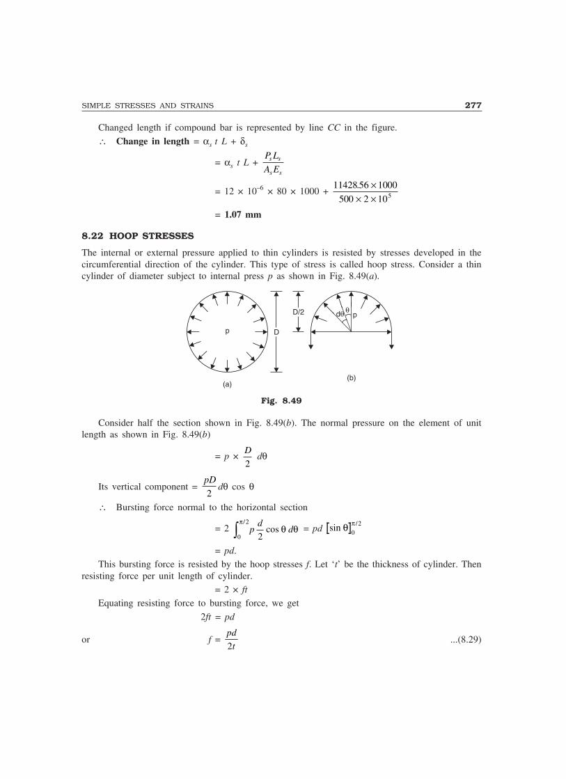
SIMPLE STRESSES AND STRAINS 277
Changed length if compound bar is represented by line CC in the figure.
∴ Change in length = αs t L + δs
= αs t L + P L
A Es s
s s
= 12 × 10–6 × 80 × 1000 + 11428 56 1000
500 2 105
. ×× ×
= 1.07 mm
8.22 HOOP STRESSES
The internal or external pressure applied to thin cylinders is resisted by stresses developed in thecircumferential direction of the cylinder. This type of stress is called hoop stress. Consider a thincylinder of diameter subject to internal press p as shown in Fig. 8.49(a).
dθ θp
p DD
D/2D/2
(a)(b)
Fig. 8.49
Consider half the section shown in Fig. 8.49(b). The normal pressure on the element of unitlength as shown in Fig. 8.49(b)
= p × D
2 dθ
Its vertical component = pD
2dθ cos θ
∴ Bursting force normal to the horizontal section
= 2 0
2
2
πθ θ
/cos� p
dd = pd sin /θ π
0
2
= pd.This bursting force is resisted by the hoop stresses f. Let ‘t’ be the thickness of cylinder. Then
resisting force per unit length of cylinder.= 2 × ft
Equating resisting force to bursting force, we get
2ft = pd
or f = pd
t2...(8.29)

278 MECHANICS OF SOLIDS
Example 8.30. A thin cylinder of internal diameter D = 1 m and thickness t = 12 mm is subjectedto internal pressure of 2 N/mm2. Determine the hoop stress developed.
Solution: Hoop stress f = pd
2t= ×
×2 1000
2 12 = 83.33 N/mm2
IMPORTANT FORMULAE
1. If stress is uniform
p = P
A
2. (i) Linear strain = Change in length
Original length
(ii) Lateral strain = Change in lateral dimension
Original lateral dimension
3. Poisson’s ratio = Lateral strain
Linear strain, within elastic limit.
4. Percentage elongation = ′ −L L
L × 100.
5. Percentage reduction in area = A A
A
− ′ × 100.
6. Nominal stress = Load
Original cross-sectional area.
7. True stress = Load
Actual cross-sectional area.
8. Factor of safety = Ultimate stress
Working stress
However in case of steel, = Yield stress
Working stress.
9. Hooke’s Law, p = Ee.
10. Extension/shortening of bar = PL
AE.
11. Extension of flat bar with linearly varying width and constant thickness = PL
tE b b( )1 2− log
b
b1
2
.
12. Extension of linearly tapering rod = 4
41 2 1 2
PL
E d d
PL
d d Eπ π=
( / ).
SIMPLE STRESSES AND STRAINS 279
13. Direct shear stress = Q
A.
14. Volumetric strain ev = δV
V = ex + ey + ez.
15. E = 2G (1 + µ) = 3K (1 – 2µ)
or9 3 1
E G K= + .
16. Extension due to rise in temperature: ∆ = α tL
17. Thermal force, P is given by
PL
AE = extension prevented.
THEORY QUESTIONS
1. Explain the terms: stress, strain, modulus of elasticity.
2. Draw a typical stress-strain curve for mild steel, indicate salient point and define them.
3. Distinguish between
(i) Elastic limit and yield point. (ii) Nominal stress and true stress.
4. Explain the term factor of safety.
5. A bar of uniform thickness t tapers uniformly from a width b1 at one end to b2 at the other end ina length L. Find the expression for its extension under an axial pull P.
6. A tapering rod has diameter d1 at one end and it tapers uniformly to a diameter d2 at the other endin a length L. If the modulus of elasticity is E, find the change in length when subjected to anaxial force P.
7. Show that pure shear gives rise to tensile and compressive stresses across the planes inclined at45° to the shearing planes, the intensity of the direct stresses being of the same magnitude asshearing stress.
8. Show that volumetric strain in a bar is equal to the sum of strains in three mutually perpendiculardirections.
9. Explain the terms:
(i) Modulus of elasticity (ii) Modulus of rigidity and
(iii) Bulk modulus.
10. Derive the relationship between
(i) Modulus of elasticity and modulus of rigidity
(ii) Modulus of elasticity and bulk modulus.
11. Show that in a compound bar of length L, when temperature increases by t, the force ‘P’ developedis given by
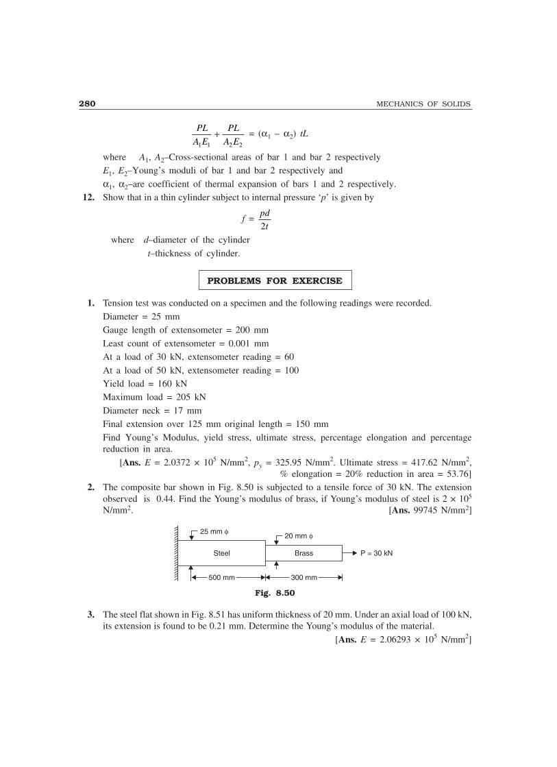
280 MECHANICS OF SOLIDS
PL
A E
PL
A E1 1 2 2
+ = (α1 – α2) tL
where A1, A2–Cross-sectional areas of bar 1 and bar 2 respectivelyE1, E2–Young’s moduli of bar 1 and bar 2 respectively and
α1, α2–are coefficient of thermal expansion of bars 1 and 2 respectively.12. Show that in a thin cylinder subject to internal pressure ‘p’ is given by
f = pd
t2
where d–diameter of the cylinder
t–thickness of cylinder.
PROBLEMS FOR EXERCISE
1. Tension test was conducted on a specimen and the following readings were recorded.
Diameter = 25 mmGauge length of extensometer = 200 mm
Least count of extensometer = 0.001 mmAt a load of 30 kN, extensometer reading = 60
At a load of 50 kN, extensometer reading = 100Yield load = 160 kNMaximum load = 205 kN
Diameter neck = 17 mmFinal extension over 125 mm original length = 150 mm
Find Young’s Modulus, yield stress, ultimate stress, percentage elongation and percentagereduction in area.
[Ans. E = 2.0372 × 10⁵ N/mm2, py = 325.95 N/mm2. Ultimate stress = 417.62 N/mm2,% elongation = 20% reduction in area = 53.76]
2. The composite bar shown in Fig. 8.50 is subjected to a tensile force of 30 kN. The extensionobserved is 0.44. Find the Young’s modulus of brass, if Young’s modulus of steel is 2 × 10⁵
N/mm2. [Ans. 99745 N/mm2]
Steel Brass
500 mm 300 mm
25 mm �20 mm �
P = 30 kN
Fig. 8.50
3. The steel flat shown in Fig. 8.51 has uniform thickness of 20 mm. Under an axial load of 100 kN,its extension is found to be 0.21 mm. Determine the Young’s modulus of the material.
[Ans. E = 2.06293 × 10⁵ N/mm2]

SIMPLE STRESSES AND STRAINS 281
b = 801b = 801100 kN
b = 40 mm2
P = 100 kN
500 mm500 mm
Fig. 8.51
4. Find the extension of the bar shown in Fig. 8.52 under an axial load of 25 kN.
[Ans. ∆ = 0.555 mm]
P
�1 = 25 mm�2 = 15 mm
P = 25 kN
400 mm400 mm 400 mm400 mm 400 mm400 mm
Fig. 8.52
5. The compound bar shown in Fig. 8.54 consists of three materials and supports a rigid horizontalplatform. Find the stresses developed in each bar, if the platform remains horizontal even afterthe loading with 100 kN. Given
Bar 1 Bar 2 Bar 3
Length 1200 mm 1500 mm 1800 mm
C.S. Area 800 mm2 1000 mm2 1200 mm2
Young’s modulus 2 × 10⁵ N/mm2 1.2 × 10⁵N/mm2 1.0 × 10⁵ N/mm2
[Hint: ∆1 = ∆2 = ∆3 = ∆, Find P2 – P3 in terms of P1.P1 + P2 + P3 = 100 × 103]
[Ans. p1 = 59.52 N/mm2, p2 = 28.57 N/mm2, p3 = 19.84 N/mm2]
6. The composite bar shown in Fig. 8.53 is 0.20 mm short of distance between the rigid supports atroom temperature. What is the maximum temperature rise which will not produce stresses in thebar ? Find the stresses induced in the bar when temperature rise is 60°. Given:
αs = 12 × 10–6/°C αc = 17.5 × 10⁻⁶/°C
Es = 2 × 10⁵ N/mm2 Ec = 1.2 × 10⁵ N/mm2
As = 400 mm2 Ac = 300 mm2
[Ans. (a) 42.10 °C, (b) ps = 36 N/mm2, pc = 48 N/mm2]

282 MECHANICS OF SOLIDS
100 mm100 mm
250 mm250 mm
Copper
Steel
0.2 mm
Fig. 8.53
7. At room temperature the gap between bar A and bar B shown in Fig. 8.54 is 0.2 mm. What are thestresses developed in the bars, if temperature rise is 30°C ? Given:
Aa = 800 mm2 Ab = 600 mm2
Ea = 2 × 10⁵ N/mm2 Eb = 1 × 10⁵ N/mm2
αa = 12 × 10–6/°C αb = 23 × 10–6 /°C
La = 250 mm Lb = 200 mm.[Ans. pa = 7.15 N/mm2 ; pb = 9.53 N/mm2]
Bar A Bar B
250 mm250 mm 200 mm200 mm
Fig. 8.54

9Beams
9.1 INTRODUCTION
A beam may be defined as a structural element which has one dimension considerably larger thanthe other two dimensions, namely breadth and depth, and is supported at few points. The distancebetween two adjacent supports is called span. It is usually loaded normal to its axis. The appliedloads make every cross-section to face bending and shearing. The load finally get transferred tosupports. The system of forces consisting of applied loads and reactions keep the beam in equilibrium.The reactions depend upon the type of supports and type of loading. In this chapter type of supports,types of beams and types of loading are first explained and then the methods of finding reactions,bending moment and shear forces are illustrated for the following determinate beams:
(a) Simply supported beams(b) Cantilever beams and(c) Overhanging beams.
9.2 TYPES OF SUPPORTS
Various types of supports and reactions developed are listed below:
Simple Support: If the beam rests simply on a support it iscalled a simple support. In such case the reaction at the support is atright angles to the support and the beam is free to move in the directionof its axis and also it is free to rotate about the support (Fig. 9.1).
Roller Support: In this case, beam end is supported on rollers.In such cases, reaction is normal to the support since rollers can betreated as frictionless. [Fig. 9.2 (a)]. Many mechanical componentsare having roller supports which roll between guides. In such cases,reaction will be normal to the guides, in both the direction (Fig. 9.2).At roller support beam is free to move along the support. It can rotateabout the support also.
Hinged Support: At a hinged end, a beam cannot move in any direction. However, it canrotate about the support (Fig. 9.3). Hence the support will not develop any resisting moment, but itcan develop reaction in any direction to keep the end stationary. The reaction R can be split into itshorizontal and vertical components for the purpose of analysis.
Thus, in Fig. 9.3,VA = R sin θ
283
Fig. 9.1
Fig. 9.2
9 0 °
R

284 MECHANICS OF SOLIDS
HA = R cos θFixed Support: At such supports, the beam end is not free to translate or rotate. Translation
is prevented by developing support reaction in any required direction.Referring to Fig. 9.4 the support reaction R which is at an angle θ to x axis may be
represented by HA and VA, where VA = R sin θHA = R cos θ
Rotation is prevented by developing support moment MA as shown in Fig. 9.4. Thus at fixedsupport A, there are three reactions HA, VA and MA.
RV A
A
�
RV A
A M A
�
H A H A
Fig. 9.3 Fig. 9.4
9.3 TYPES OF BEAMS
Simply Supported Beam: When both end of a beam aresimply supported it is called simply supported beam (Fig.9.5). Such a beam can support load in the direction normal toits axis.
Beam with One End Hinged and the Other onRollers: If one end of a beam is hinged and other end is onrollers, the beam can resist load in any direction (see Fig.9.6).
Over-hanging Beam: If a beam is projecting beyondthe support. It is called an over-hanging beam (Fig. 9.7). Theoverhang may be only on one side as in Fig. 9.7(a) or maybe on both sides as in Fig. 9.7(b).
Cantilever Beam: If a beam is fixed at one end andis free at the other end, it is called cantilever beam (Fig. 9.8).
Propped Cantilever: It is a beam with one end fixedand the other end simply supported (Fig. 9.9).
Both Ends Hinged: In these beams both ends will behaving hinged supports (Fig. 9.10).
Fig. 9.6
Fig. 9.7
Fig. 9.5
Fig. 9.8
Fig. 9.9
Fig. 9.10
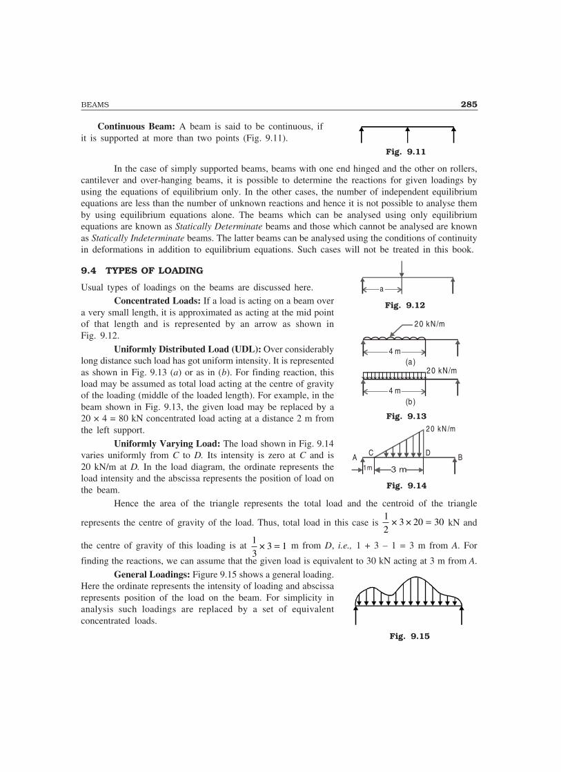
BEAMS 285
Continuous Beam: A beam is said to be continuous, ifit is supported at more than two points (Fig. 9.11).
In the case of simply supported beams, beams with one end hinged and the other on rollers,cantilever and over-hanging beams, it is possible to determine the reactions for given loadings byusing the equations of equilibrium only. In the other cases, the number of independent equilibriumequations are less than the number of unknown reactions and hence it is not possible to analyse themby using equilibrium equations alone. The beams which can be analysed using only equilibriumequations are known as Statically Determinate beams and those which cannot be analysed are knownas Statically Indeterminate beams. The latter beams can be analysed using the conditions of continuityin deformations in addition to equilibrium equations. Such cases will not be treated in this book.
9.4 TYPES OF LOADING
Usual types of loadings on the beams are discussed here.Concentrated Loads: If a load is acting on a beam over
a very small length, it is approximated as acting at the mid pointof that length and is represented by an arrow as shown inFig. 9.12.
Uniformly Distributed Load (UDL): Over considerablylong distance such load has got uniform intensity. It is representedas shown in Fig. 9.13 (a) or as in (b). For finding reaction, thisload may be assumed as total load acting at the centre of gravityof the loading (middle of the loaded length). For example, in thebeam shown in Fig. 9.13, the given load may be replaced by a20 × 4 = 80 kN concentrated load acting at a distance 2 m fromthe left support.
Uniformly Varying Load: The load shown in Fig. 9.14varies uniformly from C to D. Its intensity is zero at C and is20 kN/m at D. In the load diagram, the ordinate represents theload intensity and the abscissa represents the position of load onthe beam.
Hence the area of the triangle represents the total load and the centroid of the triangle
represents the centre of gravity of the load. Thus, total load in this case is 12
3 20 30× × = kN and
the centre of gravity of this loading is at 13
3 1× = m from D, i.e., 1 + 3 – 1 = 3 m from A. For
finding the reactions, we can assume that the given load is equivalent to 30 kN acting at 3 m from A.
General Loadings: Figure 9.15 shows a general loading.Here the ordinate represents the intensity of loading and abscissarepresents position of the load on the beam. For simplicity inanalysis such loadings are replaced by a set of equivalentconcentrated loads.
Fig. 9.11
Fig. 9.13
Fig. 9.14
Fig. 9.15
Fig. 9.12
a
(a )
20 kN/m
4 m
(b )4 m
20 kN/m
2 0 kN /m
CA BD
1m
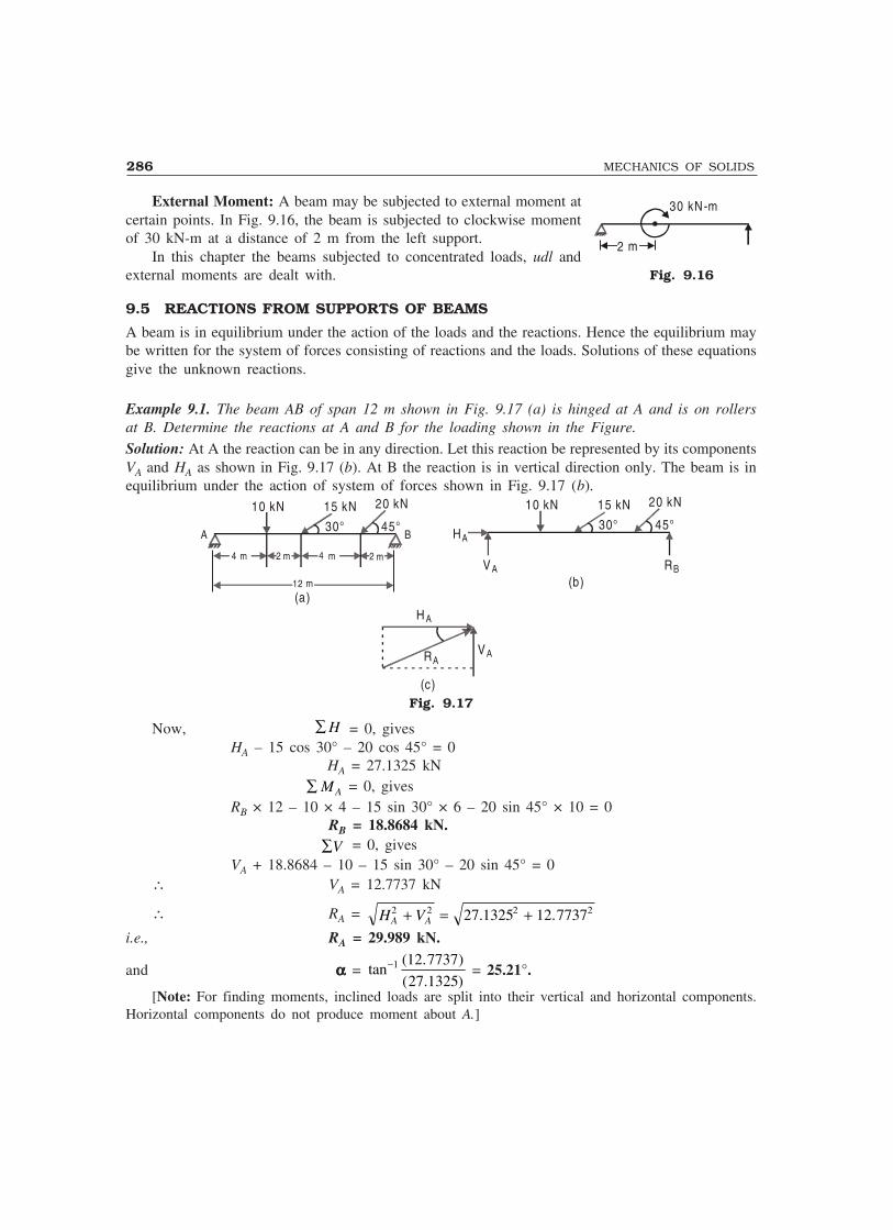
286 MECHANICS OF SOLIDS
External Moment: A beam may be subjected to external moment atcertain points. In Fig. 9.16, the beam is subjected to clockwise momentof 30 kN-m at a distance of 2 m from the left support.
In this chapter the beams subjected to concentrated loads, udl andexternal moments are dealt with.
9.5 REACTIONS FROM SUPPORTS OF BEAMS
A beam is in equilibrium under the action of the loads and the reactions. Hence the equilibrium maybe written for the system of forces consisting of reactions and the loads. Solutions of these equationsgive the unknown reactions.
Example 9.1. The beam AB of span 12 m shown in Fig. 9.17 (a) is hinged at A and is on rollersat B. Determine the reactions at A and B for the loading shown in the Figure.
Solution: At A the reaction can be in any direction. Let this reaction be represented by its componentsVA and HA as shown in Fig. 9.17 (b). At B the reaction is in vertical direction only. The beam is inequilibrium under the action of system of forces shown in Fig. 9.17 (b).
10 kN
4 m 4 m2 m
12 m
2 m
15 kN
30° 45°
20 kN 10 kN 15 kN
30° 45°
20 kN
H A
RA
(c)
VA
(a)(b)
HA
VA RB
A B
Fig. 9.17
Now, ∑ H = 0, givesHA – 15 cos 30° – 20 cos 45° = 0
HA = 27.1325 kN ∑ MA = 0, gives
RB × 12 – 10 × 4 – 15 sin 30° × 6 – 20 sin 45° × 10 = 0RB = 18.8684 kN.
∑V = 0, givesVA + 18.8684 – 10 – 15 sin 30° – 20 sin 45° = 0
∴ VA = 12.7737 kN
∴ RA = H VA A2 2 2 227 1325 12 7737+ = +. .
i.e., RA = 29.989 kN.
and ααααα = tan( . )
( . )−1 12 7737
27 1325 = 25.21°.
[Note: For finding moments, inclined loads are split into their vertical and horizontal components.Horizontal components do not produce moment about A.]
Fig. 9.16
2 m
30 kN-m

BEAMS 287
Example 9.2. Find the reactions at supports A and B in the beam AB shown in Fig. 9.18 (a).
1 m
6 m
80 kN
75° 60°
50 kN
2 m 2.5 m
60°
60 kN
60° R B
B
H A
VA
R A
H A
VA
α
(a)(b)
A 30°
Fig. 9.18
Solution: The reaction at B will be at right angles to the support, i.e., at 60° to horizontal as shownin the figure. Let the components of the reactions at A be HA and VA. Then
∑ MA = 0 gives
RB sin 60° × 6 – 60 sin 60° × 1 – 80 × sin 75° × 3 – 50 × sin 60° × 5.5 = 0
∴ RB = 100.4475 kN.
∑ H = 0, gives
HA + 60 cos 60° – 80 cos 75° + 50 cos 60° – RB cos 60° = 0 HA = –60 cos 60° + 80 cos 75° – 50 cos 60° + 100.4475 cos 60°
= 15.9293 kN
∑V = 0, gives
VA + RB sin 60° – 60 sin 60° – 80 sin 75° – 50 sin 60° = 0
VA = –100.4475 sin 60° + 60 sin 60° + 80 sin 75° + 50 sin 60° = 85.5468 kN
∴ RA = 15 9293 85 54682 2. .+
i.e., RA = 87.0172 kN.
α = tan.
.−1 85 5468
15 9293
i.e., ααααα = 79.45°, as shown in Fig. 9.18(b).
Example 9.3. Find the reactions at supports A and B of the loaded beam shown in Fig. 9.19(a).
R AVB
VB
R B
H B
H B
9m
(a) (b)
2 m 2 m1 m4 m
20 kN30 kN /m
60 kN
45° BAα
Fig. 9.19

288 MECHANICS OF SOLIDS
Solution: The reaction at A is vertical. Let HB and VB be the components of the reaction at B.∑ MB = 0, gives
RA × 9 – 20 × 7 – 30 × 4 × 5 – 60 sin 45° × 2 = 0∴ RA = 91.6503 kN.
∑ H A = 0, gives HB – 60 cos 45° = 0
∴ HB = 42.4264 kN. ∑VA = 0
91.6503 + VB – 20 – 30 × 4 – 60 sin 45° = 0VB = 90.7761 kN.
∴ RB = 42 4264 90 77612 2. .+∴ RB = 100.2013 kN.
α = tan..
−1 90 776142 4264
ααααα = 64.95°, as shown in Fig. 9.19(b).
Example 9.4. The cantilever shown in Fig. 9.20 is fixed at A and is free at B. Determine the reactionswhen it is loaded as shown in the Figure.
2 m 1 m 1 m
20 kN16 kN /m
12 kN 10 kN
H A
M A
V A
A B
Fig. 9.20
Solution: Let the reactions at A be HA, VA and MA as shown in the figureNow ΣH = 0, gives
HA = 0. ΣV = 0, gives
VA – 16 × 2 – 20 – 12 – 10 = 0∴ VA = 74 kN.
ΣM = 0, givesMA – 16 × 2 × 1 – 20 × 2 – 12 × 3 – 10 × 4 = 0
∴ MA = 148 kN-m.Example 9.5. Compute the reaction developed at support in the cantilever beam shown in Fig. 9.21.
Solution: Let the vertical reaction be VA and moment be MA. There is no horizontal component ofreactions, since no load is having horizontal component
ΣV = 0, gives
VA – 20 × 2 – 15 × 10 = 0
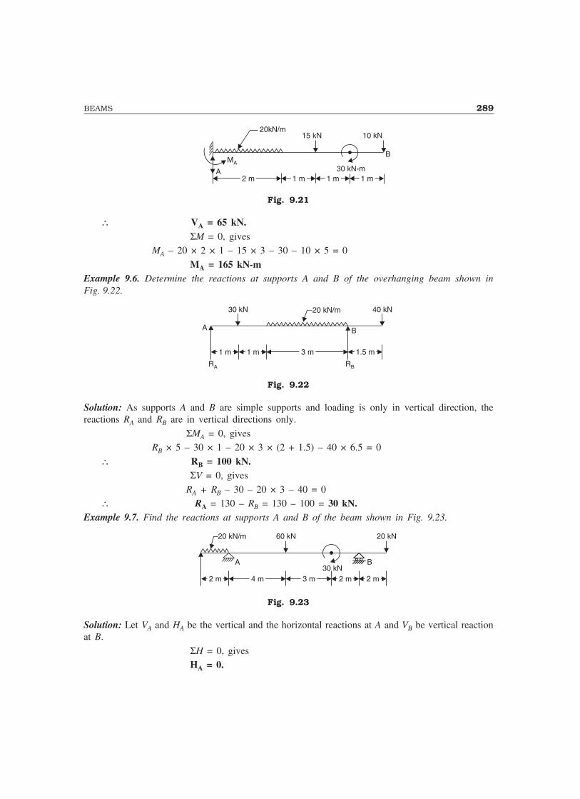
BEAMS 289
10 kN15 kN
A
B
2 m2 m
MA
1 m1 m 1 m1 m 1 m1 m
20kN/m
30 kN-m
Fig. 9.21
∴ VA = 65 kN. ΣM = 0, gives
MA – 20 × 2 × 1 – 15 × 3 – 30 – 10 × 5 = 0
MA = 165 kN-mExample 9.6. Determine the reactions at supports A and B of the overhanging beam shown inFig. 9.22.
A
1.5 m1.5 m3 m3 m1 m1 m1 m1 m
B
30 kN 40 kN20 kN/m
RA RB
Fig. 9.22
Solution: As supports A and B are simple supports and loading is only in vertical direction, thereactions RA and RB are in vertical directions only.
ΣMA = 0, givesRB × 5 – 30 × 1 – 20 × 3 × (2 + 1.5) – 40 × 6.5 = 0
∴ RB = 100 kN. ΣV = 0, gives
RA + RB – 30 – 20 × 3 – 40 = 0∴ RA = 130 – RB = 130 – 100 = 30 kN.
Example 9.7. Find the reactions at supports A and B of the beam shown in Fig. 9.23.
A
2 m2 m
B
20 kN/m 20 kN
4 m4 m 3 m3 m 2 m2 m 2 m2 m
60 kN
30 kN
Fig. 9.23
Solution: Let VA and HA be the vertical and the horizontal reactions at A and VB be vertical reactionat B.
ΣH = 0, gives HA = 0.

290 MECHANICS OF SOLIDS
ΣMA = 0, gives
– 20 × 2 × 1 + 60 × 4 + 30 + 20 × 11 – VB × 9 = 0∴ VB = 50 kN.
ΣV = 0, gives
– 20 × 2 + VA – 60 + VB – 20 = 0VA = 120 – VB = 120 – 50
VA = 70 kN.Example 9.8. Determine the reactions at A and B of the overhanging beam shown in Fig. 9.24(a).
VA R B
H A
3 m 2 m1 m2 m
40 kN-m 30 kN20 kN /m A45°
BA
VA R A
H A
α
(a ) (b )
Fig. 9.24
Solution: ∑ MA = 0
RB × 6 – 40 – 30 sin 45° × 5 – 20 × 2 × 7 = 0
RB = 71.0110 kN.
∑ H = 0
HA = 30 cos 45° = 21.2132 kN
∑V = 0
VA – 30 sin 45° + RB – 20 × 2 = 0VA = 30 sin 45° – RB + 40
VA = –9.7978(Negative sign show that the assumed direction of VA is wrong. In other words, VA is acting
vertically downwards).
RA = V HA A2 2+
RA = 23.3666 kN.
α = tan−1 V
HA
A ααααα = 24.79°, as shown in Fig. 9.24(b).
Example 9.9. A beam AB 20 m long supported on two intermediate supports 12 m apart, carriesa uniformly distributed load of 6 kN/m and two concentrated loads of 30 kN at left end A and 50kN at the right end B as shown in Fig. 9.25. How far away should the first support C be locatedfrom the end A so that the reactions at both the supports are equal ?
Solution: Let the left support C be at a distance x metres from A.Now, RC = RD (given)
∑V = 0, gives
RC + RD – 30 – 6 × 20 – 50 = 0

BEAMS 291
or 2RC = 30 + 120 + 50 since RC = RD
or RC = 100 kN
∴ RD = 100 kN
∑ MA = 0, gives
100x + 100 (12 + x) – 6 × 20 × 10 – 50 × 20 = 0
200x = 1000
x = 5 m.
R DR C20 m
x 12 m
30 kN
6 kN /m
A
50 kN
C DB
Fig. 9.25
9.6 SHEAR FORCE AND BENDING MOMENT
The load applied on a beam gets transferred to supports. To see how this transfer takes place,consider a simply supported beam subject to the loads as shown in Fig. 9.26.
∑ MB = 0, gives
RA × 7 = 20 × 5 + 40 × 3 + 60 × 1 RA = 40 kN
RB = (20 + 40 + 60) – 40= 80 kN
2 m 2 m 1 m
20 kN 40 kN 60 kN
A B2 m
Fig. 9.26
Now to find what is happening at a section, consider the section at C which is at a distance of3 m from A. Imagining a cut at this section, left hand side portion and right hand side portions aredrawn separately in Fig. 9.27.
3 m
4 m
20 kN
20 kN
20 kN
100 kN-m
100 kN-m40 kN
60 kN
BC
80 kN
40 kNA
Fig. 9.27

292 MECHANICS OF SOLIDS
Considering the algebraic sum of vertical forces acting on left hand side portion, it is found thata net vertical force of 40 – 20 = 20 kN is experienced at the section. This effect is shown in Fig.9.27 by dotted line. Again considering the portion on left hand side, the moment experienced at Cis given by
MC = 40 × 3 – 20 × 1 = 100 kN-m clockwise.
This moment is also shown on left hand side portion of the beam at C by dotted line.
Now, considering the right hand side portion:
Force experienced at C
= 80 – 60 – 40 = –20 kN
= 20 kN. downwardand the moment experienced is M = 80 × 4 – 60 × 3 – 40 × 1
= 100 kN-m. anticlockwiseThese forces and moments are also shown in Fig. 9.27 on right hand side portion of the beam
at C.Thus the section C is subjected to a force of 20 kN, which is trying to shear off the beam as
shown in Fig. 9.28(a), and is also subjected to a moment of 100 kN-m which is trying to bend thebeam as shown in Fig. 9.28(b). Since this force of 20 kN is trying to shear off the section, it is calledas shear force at section C. The moment is trying to bend the beam at C and hence it is called asbending moment at that section. The shear force and bending moment at a section in a beam maybe defined as follows:
F
F
(a) Shear fo rce a t C
(b) Bend ing mom ent a t C
A B
A BM
C
CF
M
C
Fig. 9.28
“Shear Force at a section in a beam (or any structural member) is the force that is trying to shearoff the section and is obtained as algebraic sum of all the forces acting normal to the axis of beameither to the left or to the right of the section”.
“Bending Moment at a section in a beam is the moment that is trying to bend the beam and isobtained as algebraic sum of moment of all the forces about the section, acting either to the left orto the right of the section”.
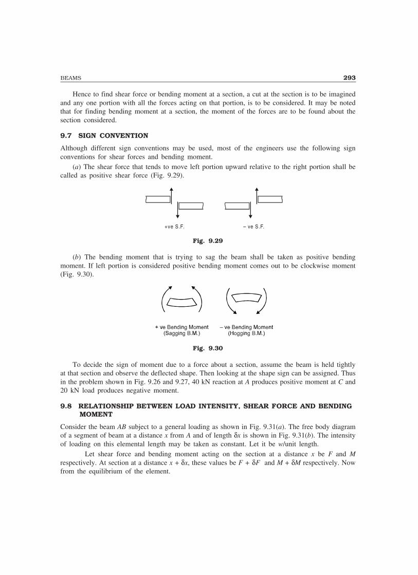
BEAMS 293
Hence to find shear force or bending moment at a section, a cut at the section is to be imaginedand any one portion with all the forces acting on that portion, is to be considered. It may be notedthat for finding bending moment at a section, the moment of the forces are to be found about thesection considered.
9.7 SIGN CONVENTION
Although different sign conventions may be used, most of the engineers use the following signconventions for shear forces and bending moment.
(a) The shear force that tends to move left portion upward relative to the right portion shall becalled as positive shear force (Fig. 9.29).
+ve S.F. – ve S .F.
Fig. 9.29
(b) The bending moment that is trying to sag the beam shall be taken as positive bendingmoment. If left portion is considered positive bending moment comes out to be clockwise moment(Fig. 9.30).
Fig. 9.30
To decide the sign of moment due to a force about a section, assume the beam is held tightlyat that section and observe the deflected shape. Then looking at the shape sign can be assigned. Thusin the problem shown in Fig. 9.26 and 9.27, 40 kN reaction at A produces positive moment at C and20 kN load produces negative moment.
9.8 RELATIONSHIP BETWEEN LOAD INTENSITY, SHEAR FORCE AND BENDING MOMENT
Consider the beam AB subject to a general loading as shown in Fig. 9.31(a). The free body diagramof a segment of beam at a distance x from A and of length δx is shown in Fig. 9.31(b). The intensityof loading on this elemental length may be taken as constant. Let it be w/unit length.
Let shear force and bending moment acting on the section at a distance x be F and Mrespectively. At section at a distance x + δx, these values be F + δF and M + δM respectively. Nowfrom the equilibrium of the element.
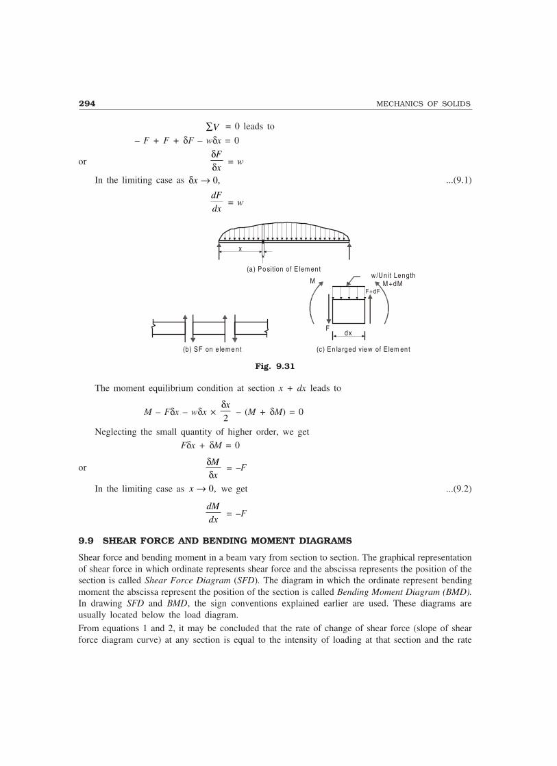
294 MECHANICS OF SOLIDS
∑V = 0 leads to
– F + F + δF – wδx = 0
orδδF
x = w
In the limiting case as δx → 0, ...(9.1)
dF
dx = w
x
(a ) Po sition of E lem ent
(b ) SF on e leme nt
Mw/Un it Length
M +dMF +dF
Fdx
(c) En la rged v iew of E lem ent
Fig. 9.31
The moment equilibrium condition at section x + dx leads to
M – Fδx – wδx × δx
2 – (M + δM) = 0
Neglecting the small quantity of higher order, we get
Fδx + δM = 0
orδδMx
= –F
In the limiting case as x → 0, we get ...(9.2)
dM
dx = –F
9.9 SHEAR FORCE AND BENDING MOMENT DIAGRAMS
Shear force and bending moment in a beam vary from section to section. The graphical representationof shear force in which ordinate represents shear force and the abscissa represents the position of thesection is called Shear Force Diagram (SFD). The diagram in which the ordinate represent bendingmoment the abscissa represent the position of the section is called Bending Moment Diagram (BMD).In drawing SFD and BMD, the sign conventions explained earlier are used. These diagrams areusually located below the load diagram.From equations 1 and 2, it may be concluded that the rate of change of shear force (slope of shearforce diagram curve) at any section is equal to the intensity of loading at that section and the rate

BEAMS 295
of change of bending moment (i.e., shape of bending moment diagram curve) is equal to the shearforce at that section. From equation 2, it can also be concluded that the bending moment will bemaximum/minimum where shear force (dM/dx) is zero.
At any section, if moment changes its sign the point representing that section is called the pointof contraflexure. Obviously, the moment at that section is zero.
9.10 SFD AND BMD FOR A FEW STANDARD CASES
The methods of drawing shear force and bending moment diagrams have been explained here in caseof the following beams subjected to standard loading conditions.
(a) Cantilever beams
(b) Simply supported beams and(c) Overhanging beams
9.10.1 Cantilever Subject to a Concentrated Load at Free End
Consider the section X–X at a distance x from free end in a cantilever beam shown inFig. 9.32(a).
From left hand side segment of beam,
F = –W
Thus shear force is constant i.e., it will not vary with x. Hence the SFD is as shown inFig. 9.32(b).
M = –Wx, linear variation.
At x = 0, MA = 0
x x
W
A x B
(a) Load D iagram
(b) SFD
W– ve
– ve W l
(c) BM D
Fig. 9.32
At x = l, MB = –Wl
Hence BMD is as shown in Fig. 9.32(c).
9.10.2 A Cantilever Subject to UDL Over its Entire Span
Consider the beam shown in Fig. 9.33(a).

296 MECHANICS OF SOLIDS
Considering the left hand side portion of the beam from the section X–X which is at a distancex from the free end A,
F = –Wx, linear variationAt x = 0, FA = 0
At x = l, FB = –wl
x
xw /un it length
A x B
(a) L oad D ia gram
(b) S FDw l
– ve
– ve
(c) B M D
l
w2l2
Fig. 9.33
Hence SFD is as shown in Fig. 9.33(b).
M = − = −wxx wx
2 2
2
This is parabolic variation. As magnitude increases at a faster rate with x, it is concave parabolaas shown in Fig. 9.33(c), with extreme values as given below:
At x = 0, MA = 0,
At x = l, Mwl
B = −2
2
9.10.3 Simply Supported Beam Subjected to a Concentrated Load
Let W be the concentrated load acting on beam AB at a distance ‘a’ from the end A as shown in Fig.9.34(a).
Now RA = Wb
land RB =
Wa
lConsider the portion AC. At any distance x from A,
F = RA = Wb
l, constant
M = RA x = Wb
lx, linear variation.
At x = 0, MA = 0
At x = a, MC = Wab
l
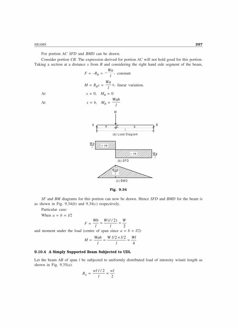
BEAMS 297
For portion AC SFD and BMD can be drawn.
Consider portion CB. The expression derived for portion AC will not hold good for this portion.Taking a section at a distance x from B and considering the right hand side segment of the beam,
F = –RB = − Wa
l, constant
M = RBx = Wa
lx , linear variation.
At x = 0, MB = 0
At x = b, MB = Wab
l
W
A B
(a) L oad D iag ra m
C bal
(c) B M D
W abl
(b ) S F D
W al
+ ve
– ve
W bl
Fig. 9.34
SF and BM diagrams for this portion can now be drawn. Hence SFD and BMD for the beam isas shown in Fig. 9.34(b) and 9.34(c) respectively.
Particular case:
When a = b = l/2
F = Wb
l
W l
l
W= =( / )2
2and moment under the load (centre of span since a = b = l/2)
M = Wab
l
W l l
l
Wl= × =/ /2 2
4
9.10.4 A Simply Supported Beam Subjected to UDL
Let the beam AB of span l be subjected to uniformly distributed load of intensity w/unit length asshown in Fig. 9.35(a).
RA = wl l
l
wl. / 2
2=
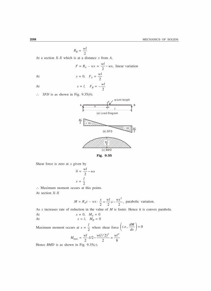
298 MECHANICS OF SOLIDS
RB = wl
2At a section X–X which is at a distance x from A,
F = RA – wx = wl
wx2
− , linear variation
At x = 0, FA = wl
2
At x = l, FB = − wl
2
∴ SFD is as shown in Fig. 9.35(b).
A B
(a) Load D iagram
(b) SF D
(c) BM D
xl
+ ve
– ve
w8l2
x
xw /unit length
w2
l
w2
l
Fig. 9.35
Shear force is zero at x given by
0 = wl
wx2
−
x = l
2∴ Maximum moment occurs at this points.At section X–X
M = RAx – wx . x wlx
wx
2 2 2
2
= − , parabolic variation.
As x increases rate of reduction in the value of M is faster. Hence it is convex parabola.At x = 0, MA = 0At x = l, MB = 0
Maximum moment occurs at x = l
2 where shear force i e
dM
dx. . ,���
���
= 0
Mmax = wl
lw l wl
22
22 8
2 2. /
( / )− =
Hence BMD is as shown in Fig. 9.35(c).

BEAMS 299
9.10.5 Overhanging Beam Subjected to a Concentrated Load at Free End
Consider the overhanging beam ABC of span AB = l and overhang BC = a, subjected to a concentratedload W at free end as shown in Fig. 9.36(a).
W
A C
(a) Load D iagram
(b) SFD
(c) BM D Wa
Bl
+ ve
– veWal
a
R A
W
– ve
Fig. 9.36
RA = Wa
l, downward
∴ RB = WWa
lW l
a
l+ = +�
�����
Portion AB:
Measuring x from A and considering left side of the section.
F = –RA = − Wa
l, constant
M = –RAx = − Wax
l, linear variation.
At x = 0, MA = 0
At x = l, MB = –Wa
Portion BC:
Measuring x from C, shear force and bending moments at that section are given byF = W, constant
M = –Wx, linear variation.At x = 0, MC = 0
At x = a, MB = –Wa.
SFD and BMD for the entire beam is shown in Fig. 9.36(b) and 9.36(c) respectively.
Example 9.10. Draw shear force and bending moment diagram for the cantilever beam shown inFig. 9.37(a).
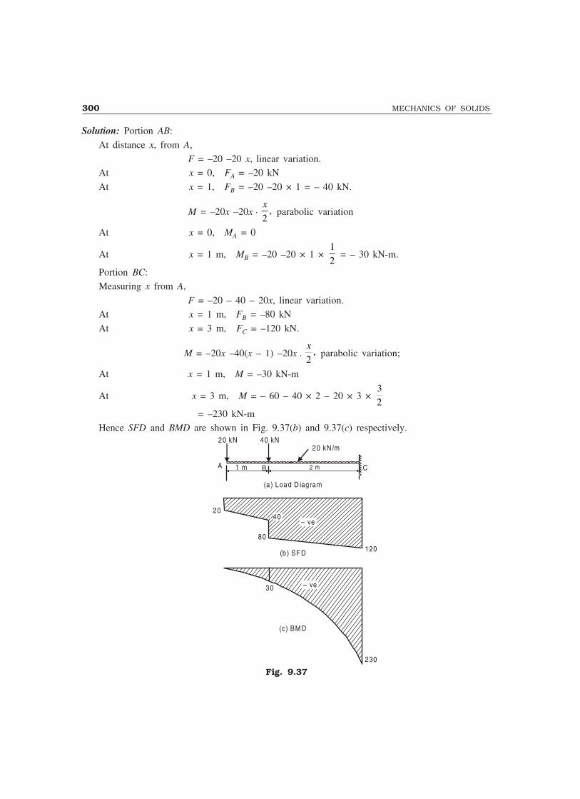
300 MECHANICS OF SOLIDS
Solution: Portion AB:
At distance x, from A, F = –20 –20 x, linear variation.
At x = 0, FA = –20 kN
At x = 1, FB = –20 –20 × 1 = – 40 kN.
M = –20x –20x .x
2, parabolic variation
At x = 0, MA = 0
At x = 1 m, MB = –20 –20 × 1 × 12
= – 30 kN-m.
Portion BC:Measuring x from A,
F = –20 – 40 – 20x, linear variation.At x = 1 m, FB = –80 kN
At x = 3 m, FC = –120 kN.
M = –20x –40(x – 1) –20x .x
2, parabolic variation;
At x = 1 m, M = –30 kN-m
At x = 3 m, M = – 60 – 40 × 2 – 20 × 3 × 32
= –230 kN-mHence SFD and BMD are shown in Fig. 9.37(b) and 9.37(c) respectively.
A C
(a) Load D iagram
1 m 2 m
20 kN /m
B
40 kN20 kN
– ve40
120
80
20
(b) SFD
230
– ve30
(c) BM D
Fig. 9.37
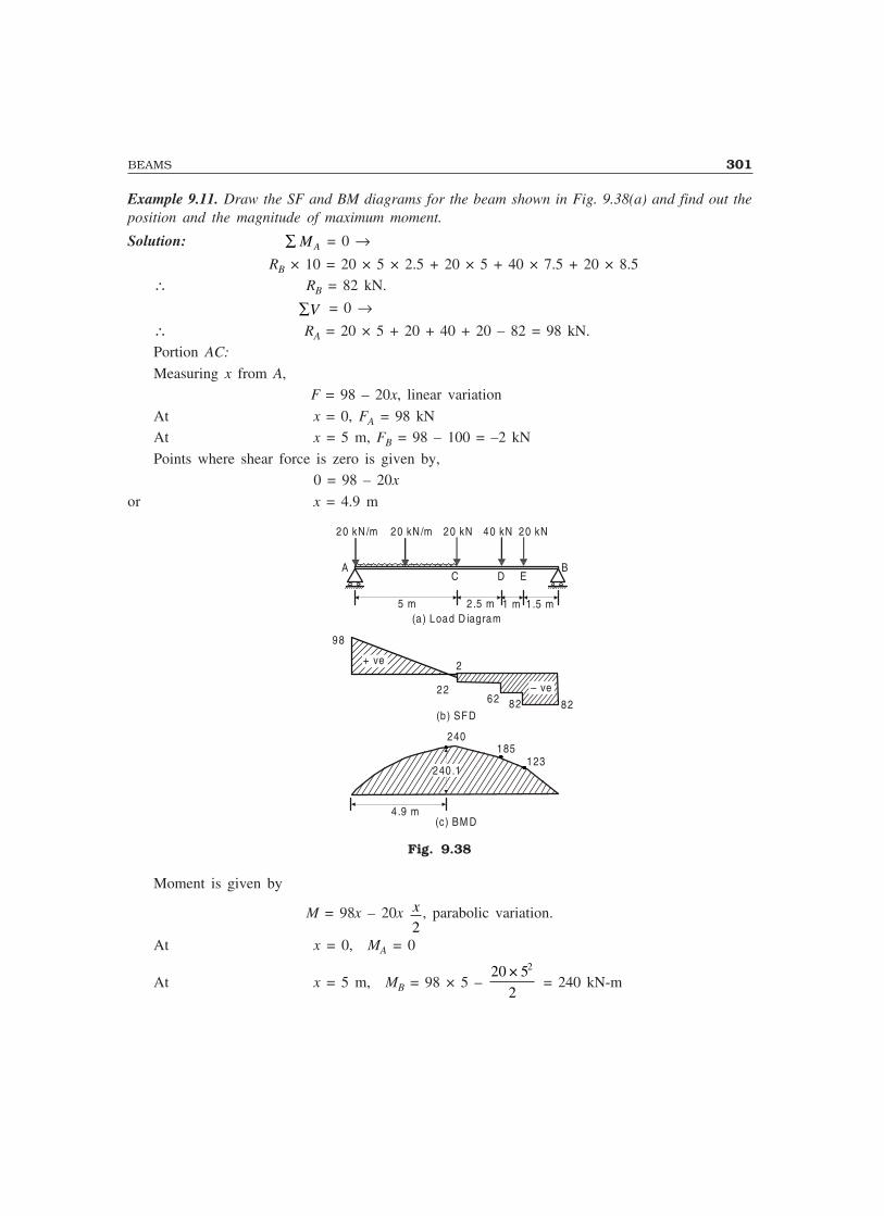
BEAMS 301
Example 9.11. Draw the SF and BM diagrams for the beam shown in Fig. 9.38(a) and find out theposition and the magnitude of maximum moment.
Solution: ∑ MA = 0 →RB × 10 = 20 × 5 × 2.5 + 20 × 5 + 40 × 7.5 + 20 × 8.5
∴ RB = 82 kN.
∑V = 0 →∴ RA = 20 × 5 + 20 + 40 + 20 – 82 = 98 kN.Portion AC:
Measuring x from A, F = 98 – 20x, linear variation
At x = 0, FA = 98 kNAt x = 5 m, FB = 98 – 100 = –2 kN
Points where shear force is zero is given by,0 = 98 – 20x
or x = 4.9 m
(c) BM D
AC D E
(a) Load D iagram
B
20 kN20 kN /m
2
98
(b) SFD
4.9 m
40 kN 20 kN
5 m 2.5 m 1 m 1.5 m
– ve2262 82 82
240.1
240185
123
+ ve
20 kN /m
Fig. 9.38
Moment is given by
M = 98x – 20x x2
, parabolic variation.
At x = 0, MA = 0
At x = 5 m, MB = 98 × 5 – 20 5
2
2× = 240 kN-m
302 MECHANICS OF SOLIDS
Maximum moment occurs at x = 4.9 m where F = dM
dx= 0
Mmax = 98 × 4.9 – 20 × 4 9
2
2. = 240.1 kN-m
Portion CD:
Measuring x from B and considering right hand side segment of the beam,F = –82 + 20 + 40 = –22 kN, constant
M = 82x – 20(x – 1.5) – 40(x – 2.5)= 22x + 130, linear variation.
At x = 2.5 m, MD = 22 × 2.5 + 130 = 185 kN-mAt x = 5 m, MC = 22 × 5 + 130 = 240 kN-m.
Portion DE:
Measuring x from B and considering the portion of the beam on the right side of the section,
F = –82 + 20 = –62 kN, constant M = 82x – 20(x – 1.5) linear variation
At x = 1.5 m, ME = 82 × 1.5 = 123 kN-m.
At x = 2.5, M = 82 × 2.5 – 20 × 1 = 185 kN-m.
Portion EB:
Measuring x from B and considering the right side segment,
F = –82 kN, constant M = 82x, linear variation.
At x = 0, MB = 0At x = 1.5 m, ME = 82 × 1.5 = 123 kN-m.
SFD and BMD are shown in Fig. 9.38(b) and 9.38(c) respectively, for the entire beam.Example 9.12. A beam of span 8 m has roller support at A and hinge support at B as shown inFig. 9.39(a). Draw SF and BM diagrams when the beam is subjected to udl, a concentrated load andan externally applied moment as shown in the Figure.
Solution: ∑ MA = 0 →RB × 8 – 10 × 4 × 2 – 20 × 4 + 240 = 0
RB = –10 kN (upwards)= 10 kN. (downwards)
∑V = 0 →RA = 10 × 4 + 20 + 10 = 70 kN.
Portion AC:
Measuring x from A and considering left hand side segment of the beam,F = 70 – 10x, linear variation
At x = 0, FA = 70 kNAt x = 4 m, FC = 70 – 40 = 30 kN

BEAMS 303
M = 70x – 10x x
2, parabolic variation
At x = 0, MA = 0
At x = 4 m, MC = 70 × 4 – 10 × 4 × 42
= 200 kN-m.
Portion CD: Measuring x from B,
F = 10 kN, constantM = –10x + 240, linear variation
x = 4 m, MC = 200 kN-mAt x = 2 m, MD = –10 × 2 + 240 = 220 kN-m.
Portion DB:
Measuring x from B,
F = 10 kN, constantM = –10x, linear variation
At x = 0, MB = 0At x = 2 m, MD = –10 × 2 = –20 kN-m.
A
(a) Loading Diagram
B
20 kN10 kN /m
+ ve
70
(b) SFD
4 m 2 m
D
240 kN -m
2 m R B
R A
3010 10
(c) BMD
+ ve
220200
– ve20
C
Fig. 9.39
SFD and BMD are shown in Fig. 9.39(b) and 9.39(c).Note: The bending moment value will be the same at a point, whether calculated by considering left hand
side or the right hand side segment of the beam, if there is no external moment acting at that point. If theexternal moment is acting at a point, there will be sudden change in BMD at that point to the extent equal tothe magnitude of external bending moment.
Example 9.13. The overhanging beam ABC is supported at A and B, the span AB being 6 m. Theoverhang BC is 2 m (see Fig. 3.42 a). It carries a uniformly distributed load of 30 kN/m over a lengthof 3 m from A and concentrated load of 20 kN at free end. Draw SF and BM diagrams.

304 MECHANICS OF SOLIDS
Solution: Σ ΜΑ = 0 → RB × 6 = 20 × 8 + 30 × 3 × 1.5
∴ RB = 49.167 kN.ΣV = 0 →RA = 30 × 3 + 20 – 49.167 = 60.833 kN.
Portion AD:Measuring x from A and considering left side segment,
F = 60.833 – 30x, linear variationAt x = 0, FA = 60.833 kN.At x = 3 m,
FD = 60.833 – 30 × 3 = –29.167 kN.The point of zero shear is given by
0 = 60.833 – 30xor, x = 2.028 m.
At section X–X, the moment is given by
M = 60.833 x – 302
2x, parabolic variation
At x = 0, MA = 0At x = 3 m,
MD = 60.833 × 3 – 30 × 92
= 47.5 kN-m.
Maximum moment occurs at x = 2.028 m. since here F = dM
dx= 0
Mmax = 60.833 × 2.028 – 30 × 2 028
2
2. = 61.678 kN-m.
A
(a) Loading D iagram
B
30 kN /m
+ ve
60.833
(b) SFD
3 m 2 m
20
3 mD
C
– ve
+ ve20
29.16729.167
(c) BM D
47.5
– ve
+ ve61.678 3.371 m
2.028
40
20 kN
Fig. 9.40
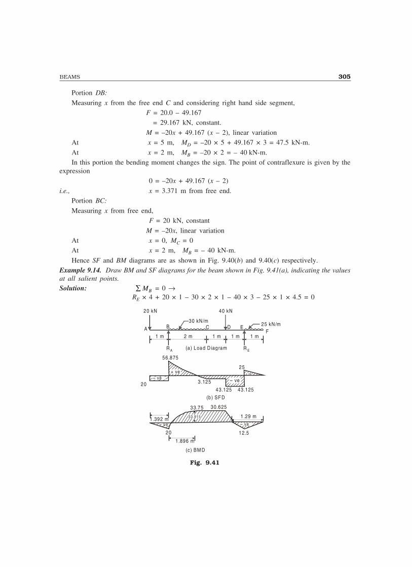
BEAMS 305
Portion DB:
Measuring x from the free end C and considering right hand side segment,F = 20.0 – 49.167
= 29.167 kN, constant.
M = –20x + 49.167 (x – 2), linear variationAt x = 5 m, MD = –20 × 5 + 49.167 × 3 = 47.5 kN-m.
At x = 2 m, MB = –20 × 2 = – 40 kN-m.In this portion the bending moment changes the sign. The point of contraflexure is given by the
expression 0 = –20x + 49.167 (x – 2)
i.e., x = 3.371 m from free end.Portion BC:
Measuring x from free end, F = 20 kN, constant
M = –20x, linear variationAt x = 0, MC = 0At x = 2 m, MB = – 40 kN-m.
Hence SF and BM diagrams are as shown in Fig. 9.40(b) and 9.40(c) respectively.Example 9.14. Draw BM and SF diagrams for the beam shown in Fig. 9.41(a), indicating the valuesat all salient points.Solution: ∑ MB = 0 →
RE × 4 + 20 × 1 – 30 × 2 × 1 – 40 × 3 – 25 × 1 × 4.5 = 0
A
(a) Load D iagram
+ ve
56.875
(b) SFD
C
– ve+ ve
25
40 kN
43.125
3.125
D E
20 kN
1 m 2 m 1 m 1 m 1 m
– ve20
43.125
B30 kN /m
25 kN /mF
(c) BM D
3 3 .9 1 5
20 12.5
33.75 30.625
1.896 m
1.392 m 1.29 m
– ve – ve
R A R E
Fig. 9.41

306 MECHANICS OF SOLIDS
RE = 68.125 kN.∑V = 0 →RB = 20 + 30 × 2 + 40 + 25 × 1 – 68.125
= 76.875 kN.Portion AB:Measuring x from A,
F = –20 kN, constant M = –20x, linear variation
At x = 0, MA = 0At x = 1 m, MB = –20 kN-mPortion BC:Measuring x from B,
F = –20 + 76.875 – 30x, linear variationAt x = 0, F = 56.875 kN.At x = 2 m, F = –3.125 kN-m.The point of zero shear force is given by
0 = –20 + 76.875 – 30x
x = 1.896 m from B.
At distance x from B the moment is given by
M = –20(x + 1) + 76.875x – 30xx
2= –20 + 56.875x – 15x2, parabolic variation
At x = 0, MB = –20 kN-m.At x = 2 m, MC = –20 + 56.875 × 2 – 15 × 4
= 33.75 kN-m.Maximum moment occurs where SF = 0. i.e., at x = 1.896 m.∴ Mmax = –20 + 56.875 × 1.896 – 15 × 1.8962
= 33.913 kN-m.The bending moment is changing its sign in this portion. Hence the point of contraflexure exists
in this portion. It is given by 0 = –20 + 56.875x – 15x2
∴ x = 0.392 m.i.e., the point of contraflexure is at 1.392 m from the free end A.
Portion CD:Measuring x from F,
Shear force = 25 × 1 – 68.125 – 40 = –3.125 kN, constant
M = –25 × 1 × (x – 0.5) + 68.125 (x – 1) – 40 ( x – 2), linear variationAt x = 3 m, MC = 33.75 kN-m.At x = 2 m, MD = –25 × 1.5 + 68.125
= 30.625 kN-m.

BEAMS 307
Portion DE:
Measuring x from free end F,
Shear force = 25 – 68.125 = – 43.125 kN, constantM = –25 (x – 0.5) + 68.125(x – 1), linear variation
At x = 2 m, MD = 30.625 kN-m.At x = 1 m, ME = –12.5 kN-m.
Portion EF: M = 0, at x = 1.29 mMeasuring x from free end F,
Shear force F = 25x, linear constantAt x = 0, FF = 0
At x = 1 m, FE = 25 kN
M = –25x.x
2, parabolic variation
At x = 0, MF = 0
At x = 1 m, ME = –12.5 kN-m.SF and BM diagrams are as shown in Fig. 9.41(b) and 9.41(c) respectively.
9.11 SHORT-CUT PROCEDURE
To save time, one can calculate the values only at salient points and draw shear force and bendingmoment diagrams, noting the following points:
(a) Wherever concentrated load is acting (including support reaction), there will be suddenchange in SF value to the extent of that force at that point, in the direction of that force (whileproceeding from left to right).
(b) If an external moment is acting at a point on the beam, there will be sudden change in thevalue of bending moment to the extent of that external bending moment. While proceeding from left,it will be increase in value, if the moment is clockwise. There will be drop in bending moment valueif the external bending moment is anticlockwise. Exactly opposite phenomenon will be observedwhile proceeding from right to left.
(c) Since dF
dxw= and
dM
dxF= , the shear force curve will be one degree higher than that of load
curve and bending moment curve will be one degree higher than that of shear force curve. The natureof variation, for various loads is listed in Table 9.1.
Table 9.1 Nature of SF and BM Variation
Load SF BM
No load Constant Linear
Uniformly distributed load Linear Parabolic
Uniformly varying load Parabolic Cubic
The following points also may be noted while drawing shear force and bending momentdiagrams:

308 MECHANICS OF SOLIDS
(a) The bending moment is maximum when shear force is zero. The location and the value ofmaximum moment should always be indicated in bending moment diagram.
(b) The point of contraflexure is an important point in a BMD, hence if it exists, its locationshould be indicated.
This method of drawing SFD and BMD is illustrated with two problems below:
Example 9.15. Determine the reactions and construct the shear force and bending moment diagramsfor the beam shown in Fig. 9.42(a). Mark the salient points and the values at those points.
Solution: ∑ MA = 0 →RB × 6 + 120 – 60 × 4 – 60 × 7 = 0
∴ RB = 90 kN.
∑V = 0 → RA = 60 + 60 – 90 = 30 kN.
SFD:
In portion ADE, F = 30 kN.In portion EB, F = 30 – 60 = –30 kN.
In portion BC, F = 60 kN.SFD is as shown in Fig. 3.45(b).
BMD:
At A, MA = 0Just to the left of D, M = 30 × 2 = 60 kN-m.
Just to the right of D, M = 30 × 2 – 120 = –60 kN-m.At E, M = –60 × 3 + 90 × 2 = 0
At B, M = –60 × 1 = –60 kN-m.At C, M = 0
BMD is as shown in Fig. 9.42(c).
A
(a) Load D iagram
120 kN-m
+ ve
30
(b) SFD
D
– ve
+ ve
(c) BM D
60 kN
E C
0
60 kN
B
30
30 30
60 60
+ ve
– ve
60
60
– ve
60
1 m2 m2 m 2 m
R A
R B
Fig. 9.42

BEAMS 309
Example 9.16. Draw the bending moment and shear force diagram for the beam loaded as shownin Fig. 9.43. (a). Mark the values at the salient points Determine the point of contraflexure also.
15 kN
A
10kN/m
B C D
E
F
20 kN
50 kN-m
4 m 2 m 2 m 2 m 2 m
68
37
+
318
38 38
0
62
26
x
+
–
(b) SFD
(a)
(b) BMD
50
RA RE
–
Fig. 9.43
Solution: ΣMA = 0, gives
RE × 10 – 10 × 4 × 2 – 15 × 6 – 20 × 8 – 50 = 0∴ RE = 38 kN
ΣV = 0, givesRA + RE – 10 × 4 – 15 – 20 = 0
RA = 75 – RE = 75 – 38 =37 kNSFD:
Values at salient points are:FA = RA = 37 kN
In portion AB, FB = 37 – 10 × 4 = – 3 kNIn portion BC, F = 37 – 40 = 3 kN
In portion CD, F = 37 – 40 – 15 = – 18 kNIn portion DE, F = 37 – 40 – 15 – 20 = – 38 kNIn portion EF, F = 0.
∴ SFD is as shown in Fig. 9.43 (b)BMD:
At A, MA = 0At B, MB = 37 × 4 – 10 × 4 × 2 = 68 kN-m
At C, MC = 37 × 6 – 10 × 4 × 4 = 62 kN-m
310 MECHANICS OF SOLIDS
At D, calculating from right hand side MD = – 50 + 38 × 2 = 26 kN-m
At E, ME = – 50 kN-mPoint of contraflexure is between D and E. Let it be at distance x from support E. Then
– 50 + 38x = 0
∴ x = 1.32 m from E as shown in Fig. 9.43 (c)BMD is as shown in Fig. 9.43 (c)
IMPORTANT FORMULAE
1. Shear force at a section of the beam = Σ all forces to the left or right of the section.2. Bending moment at a section of the beam = Σ moments of all forces to the left or to the right of the
section, moment centre being the section.
3.dF
dx = w and
dM
dx = – F
THEORY QUESTIONS
1. Explain the following types of supports to beams:
(i) Simple support (ii) Hinged support(iii) Fixed support
2. Bring out the difference between statically determinate and indeterminate beams.3. Derive the relationship between,
(i) Shear force and load intensity (ii) Bending moment and shear force
PROBLEMS FOR EXERCISE
1. Determine the reaction at A and B on the overhanging beam shown in Fig. 9.44.
AR B
2 m 3 m 1 m 2 m
30 kN20 kN /m
45°α
40 kN-mB
RA
Fig. 9.44
[Ans. RA = 23.3666 kN; a = 24.79°; RB = 71.011 kN]2. An overhanging beam is on rollers at A and is hinged at B and is loaded as shown in Fig. 9.45.
Determine the reactions at A and B.
1 m 4 m4 m
A B
10 kN/m20 kN
Fig. 9.45
[Ans. RA = 45 kN; RB = 15 kN]
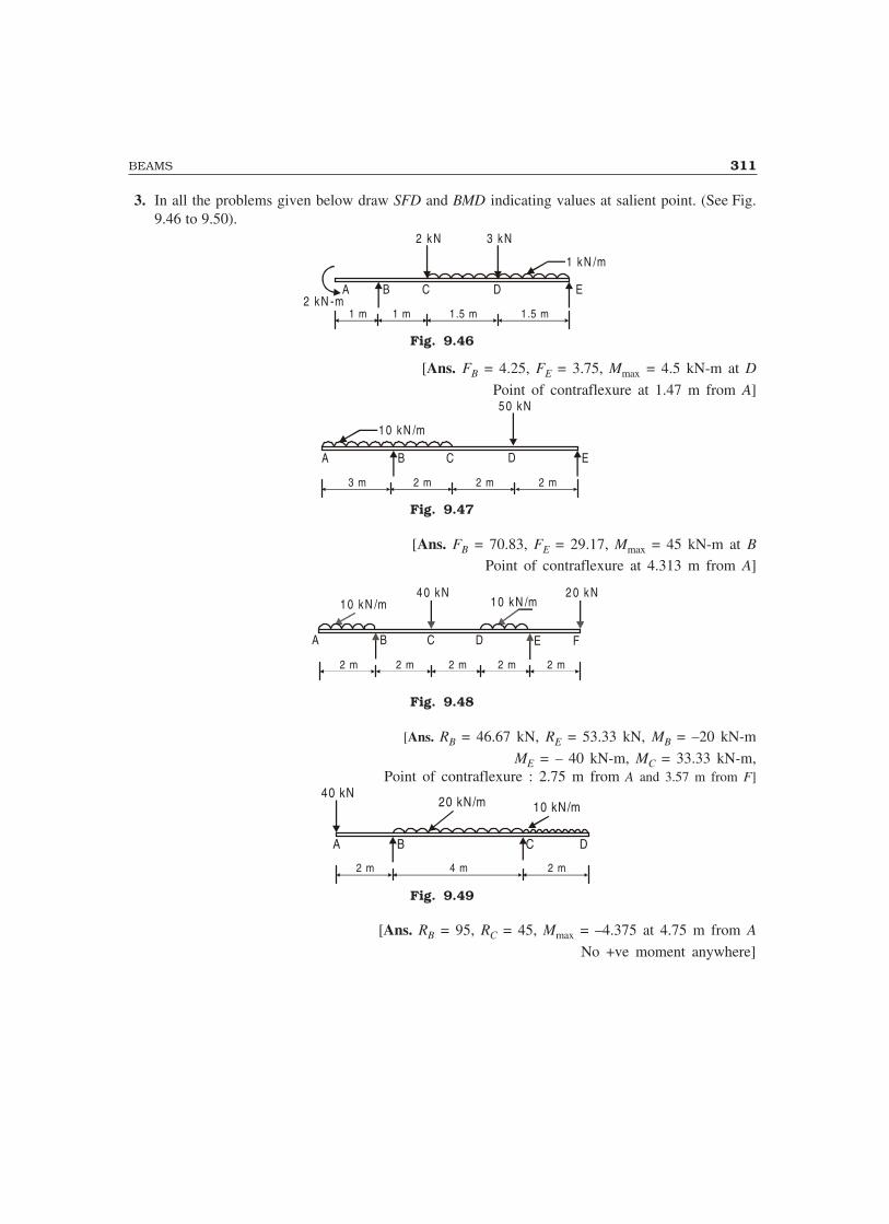
BEAMS 311
3. In all the problems given below draw SFD and BMD indicating values at salient point. (See Fig.9.46 to 9.50).
A B C D
2 kN
2 kN -m
3 kN
1 kN /m
1 m 1 m 1.5 m 1.5 m
E
Fig. 9.46
[Ans. FB = 4.25, FE = 3.75, Mmax = 4.5 kN-m at D
Point of contraflexure at 1.47 m from A]
A B C D
5 0 kN
1 0 kN /m
3 m 2 m 2 m2 m
E
Fig. 9.47
[Ans. FB = 70.83, FE = 29.17, Mmax = 45 kN-m at B
Point of contraflexure at 4.313 m from A]
A B C D
1 0 kN /m1 0 kN /m
2 m 2 m2 m
E
4 0 kN 2 0 kN
F
2 m 2 m
Fig. 9.48
[Ans. RB = 46.67 kN, RE = 53.33 kN, MB = –20 kN-m
ME = – 40 kN-m, MC = 33.33 kN-m,Point of contraflexure : 2.75 m from A and 3.57 m from F]
A B C D
20 kN/m 10 kN/m
2 m 4 m 2 m
40 kN
Fig. 9.49
[Ans. RB = 95, RC = 45, Mmax = –4.375 at 4.75 m from A
No +ve moment anywhere]
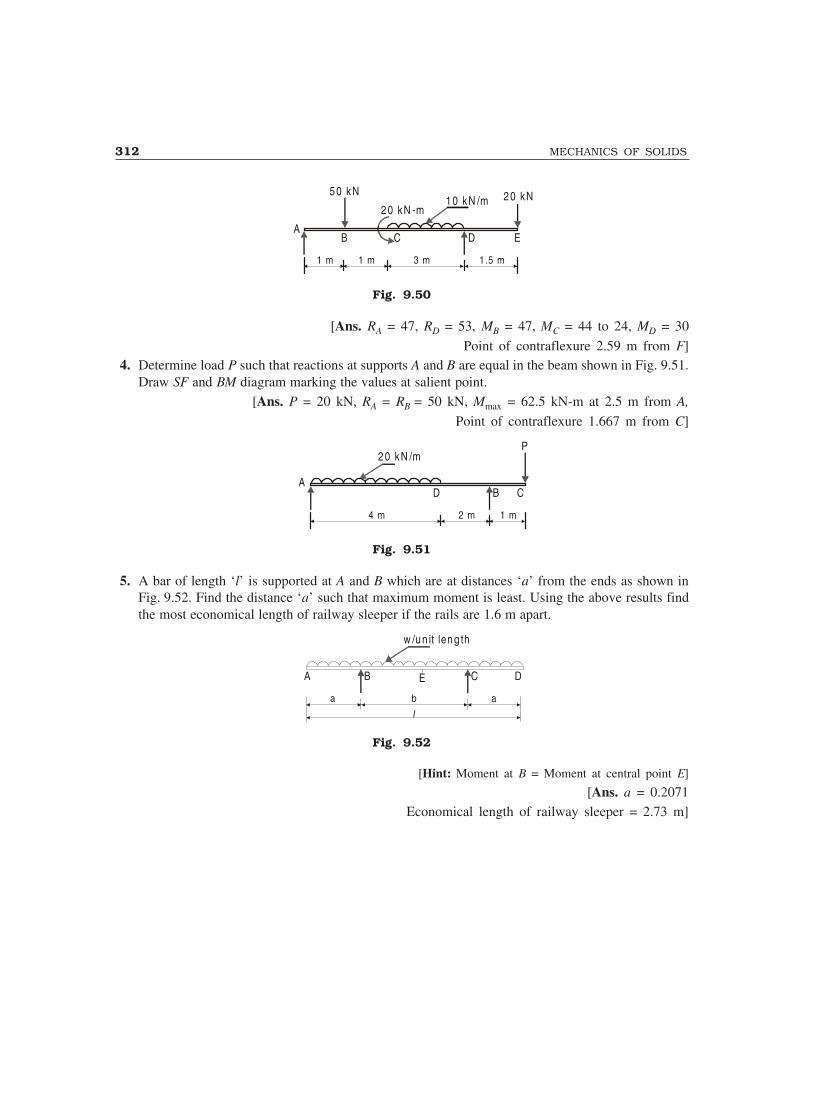
312 MECHANICS OF SOLIDS
AB C D
5 0 kN
1 m 1 m 3 m 1.5 m
E
2 0 kN -m1 0 kN /m 2 0 kN
Fig. 9.50
[Ans. RA = 47, RD = 53, MB = 47, MC = 44 to 24, MD = 30
Point of contraflexure 2.59 m from F]4. Determine load P such that reactions at supports A and B are equal in the beam shown in Fig. 9.51.
Draw SF and BM diagram marking the values at salient point.[Ans. P = 20 kN, RA = RB = 50 kN, Mmax = 62.5 kN-m at 2.5 m from A,
Point of contraflexure 1.667 m from C]
AB CD
2 0 kN /mP
4 m 2 m 1 m
Fig. 9.51
5. A bar of length ‘l’ is supported at A and B which are at distances ‘a’ from the ends as shown inFig. 9.52. Find the distance ‘a’ such that maximum moment is least. Using the above results findthe most economical length of railway sleeper if the rails are 1.6 m apart.
A B DE
w /u n it len g th
C
l
a b a
Fig. 9.52
[Hint: Moment at B = Moment at central point E]
[Ans. a = 0.2071Economical length of railway sleeper = 2.73 m]
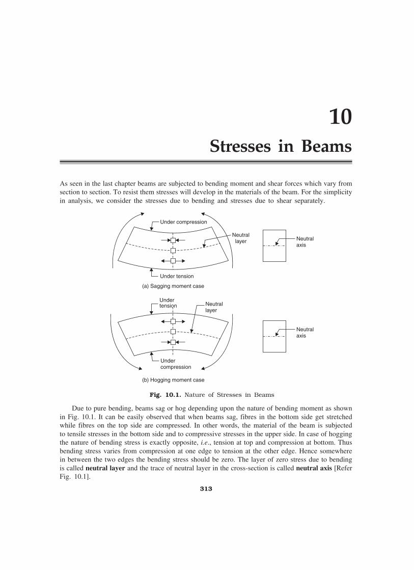
10Stresses in Beams
As seen in the last chapter beams are subjected to bending moment and shear forces which vary fromsection to section. To resist them stresses will develop in the materials of the beam. For the simplicityin analysis, we consider the stresses due to bending and stresses due to shear separately.
Under compression
Under tension
Neutrallayer
(a) Sagging moment case
Undercompression
Undertension Neutral
layer
Neutralaxis
Neutralaxis
(b) Hogging moment case
Fig. 10.1. Nature of Stresses in Beams
Due to pure bending, beams sag or hog depending upon the nature of bending moment as shownin Fig. 10.1. It can be easily observed that when beams sag, fibres in the bottom side get stretchedwhile fibres on the top side are compressed. In other words, the material of the beam is subjectedto tensile stresses in the bottom side and to compressive stresses in the upper side. In case of hoggingthe nature of bending stress is exactly opposite, i.e., tension at top and compression at bottom. Thusbending stress varies from compression at one edge to tension at the other edge. Hence somewherein between the two edges the bending stress should be zero. The layer of zero stress due to bendingis called neutral layer and the trace of neutral layer in the cross-section is called neutral axis [ReferFig. 10.1].
313

314 MECHANICS OF SOLIDS
10.1 ASSUMPTIONS
Theory of simple bending is developed with the following assumptions which are reasonably acceptable:(i) The material is homogeneous and isotropic.
(ii) Modulus of elasticity is the same in tension and in compression.
(iii) Stresses are within the elastic limit.
(iv) Plane section remains plane even after deformations.
(v) The beam is initially straight and every layer of it is free to expand or contract.
(vi) The radius of curvature of bent beam is very large compared to depth of the beam.
10.2 BENDING EQUATION
There exists a define relationship among applied moment, bending stresses and bending deformation(radius of curvature). This relationship can be derived in two steps:
(i) Relationship between bending stresses and radius of curvature.(ii) Relationship between applied bending moment and radius of curvature.
(i) Relationship between bending stresses and radius of curvature: Consider an elemental lengthAB of the beam as shown in Fig. 10.2(a). Let EF be the neutral layer and CD the bottommost layer. If GH is a layer at distance y from neutral layer EF, initially AB = EF = GH =CD.
EG
FH
A
C
B
D
y
(a) (b)
E�
G�
F�
H�
C� D�
A� B�
RR
�
Fig. 10.2
Let after bending A, B, C, D, E, F, G and H take positions A′, B′, C′, D′, E′, F′, G′ and H′respectively as shown in Fig. 10.2(b). Let R be the radius of curvature and φ be the angle subtendedby C′A′ and D′B′ at centre of radius of curvature. Then,
EF = E′F′, since EF is neutral axis
= Rφ ...(i)
Strain in GH = Final length – Initial length
Initial length

STRESSES IN BEAMS 315
= G H GH
GH
′ ′ −
But GH = EF (The initial length)= Rφ
and G′H′ = (R + y) φ
∴ Strain in layer GH = ( )R y R
R
+ −φ φφ
= y
R...(ii)
Since strain in GH is due to tensile forces, strain in GH = f/E ...(iii)
where f is tensile stress and E is modulus of elasticity.From eqns. (ii) and (iii), we get
f
E
y
R=
orfy
ER
= ...(10.1)
(ii) Relationship between bending moment and radius of curvature: Consider an elemental areaδa at distance y from neutral axis as shown in Fig. 10.3.
y
�a
Fig. 10.3
From eqn. 10.1, stress on this element is
f = E
R y ...(i)
∴ Force on this element
= E
R y δa
Moment of resistance of this elemental force about neutral axis
= E
R y δa y
= E
R y2 δa
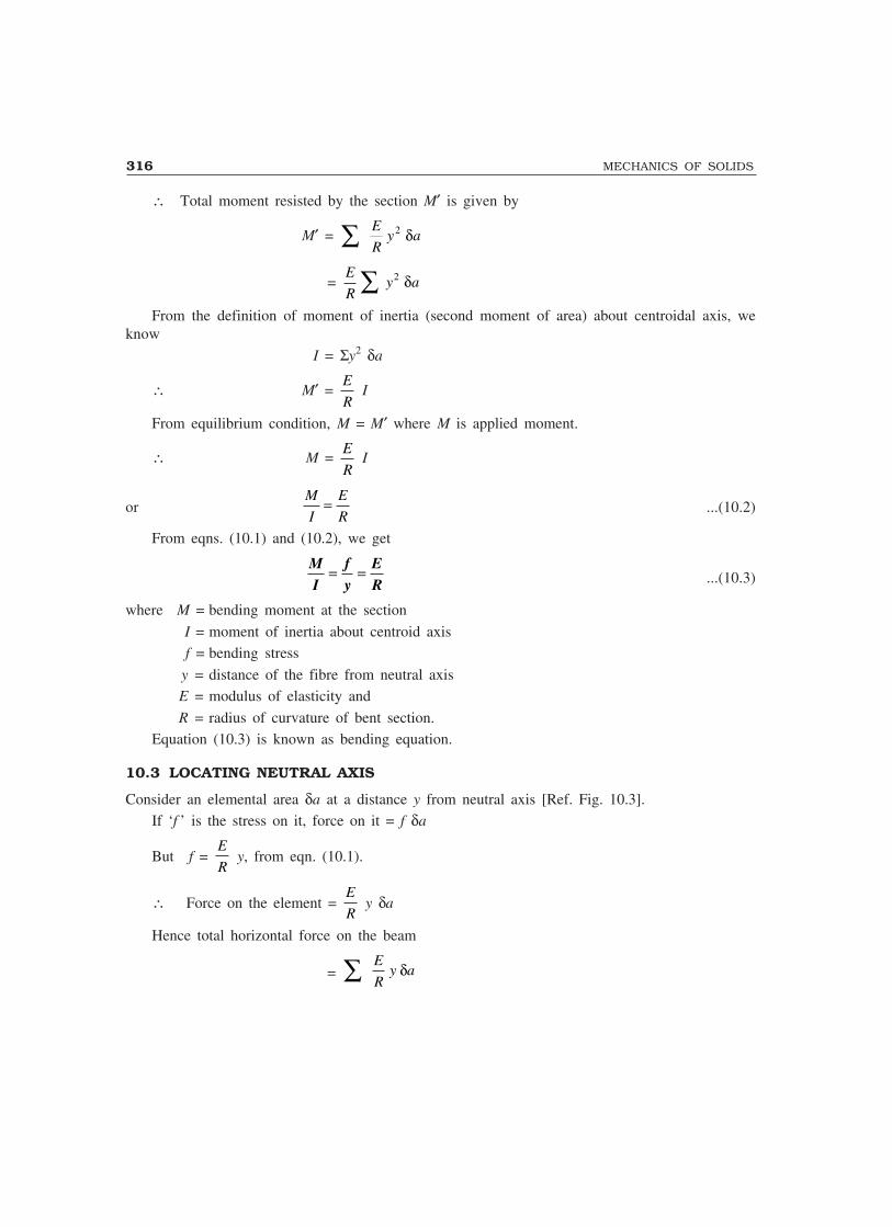
316 MECHANICS OF SOLIDS
∴ Total moment resisted by the section M′ is given by
M′ = ∑ E
Ry a2 δ
= E
Ry a2 δ∑
From the definition of moment of inertia (second moment of area) about centroidal axis, weknow
I = Σy2 δa
∴ M′ = E
R I
From equilibrium condition, M = M′ where M is applied moment.
∴ M = E
R I
orM
I
E
R= ...(10.2)
From eqns. (10.1) and (10.2), we get
MI
fy
ER
= = ...(10.3)
where M = bending moment at the section
I = moment of inertia about centroid axisf = bending stress
y = distance of the fibre from neutral axisE = modulus of elasticity and
R = radius of curvature of bent section.Equation (10.3) is known as bending equation.
10.3 LOCATING NEUTRAL AXIS
Consider an elemental area δa at a distance y from neutral axis [Ref. Fig. 10.3].If ‘f ’ is the stress on it, force on it = f δa
But f = E
R y, from eqn. (10.1).
∴ Force on the element = E
R y δa
Hence total horizontal force on the beam
= ∑ E
Ry aδ
STRESSES IN BEAMS 317
= E
Ry aΣ δ
Since there is no other horizontal force, equilibrium condition of horizontal forces gives
E
Ry aΣ δ = 0
As E
R is not zero,
Σy aδ = 0 ...(i)
If A is total area of cross-section, from eqn. (i), we get
∑ y a
A
δ = 0 ...(ii)
Noting that Σyδa is the moment of area about neutral axis, Σy a
A
δ should be the distance of
centroid of the area from the neutral axis. Hence Σy a
A
δ = 0 means the neutral axis coincides with
the centroid of the cross-section.
10.4 MOMENT CARRYING CAPACITY OF A SECTION
From bending equation, we haveM
I
f
y=
i.e., f = M
I y ...(i)
Hence bending stress is maximum, when y is maximum. In other words, maximum stress occursin the extreme fibres. Denoting extreme fibre distance from neutral fibre as ymax equation (i) will be
fmax = M
I ymax ...(ii)
In a design fmax is restricted to the permissible stress in the material. If fper is the permissiblestress, then from equation (ii),
fper = M
I ymax
∴ M = I
ymax
fper
The moment of inertia I and extreme fibre distance from neutral axis ymax are the properties of
section. Hence I
ymax
is the property of the section of the beam. This term is known as modulus of
section and is denoted by Z. Thus

318 MECHANICS OF SOLIDS
Z = I
ymax
...(10.4)
and M = fper Z ...(10.5)
Note : If moment of inertia has unit mm4 and ymax has mm, Z has the unit mm3.
The eqn. (10.5) gives permissible maximum moment on the section and is known as momentcarrying capacity of the section. Since there is definite relation between bending moment and theloading given for a beam it is possible to find the load carrying capacity of the beam by equatingmaximum moment in the beam to moment carrying capacity of the section. Thus
Mmax = fper Z ...(10.6)If permissible stresses in tension and compressions are different for a material, moment carrying
capacity in tension and compression should be found separately and equated to maximum values ofmoment creating tension and compression separately to find the load carrying capacity. The lowerof the two values obtained should be reported as the load carrying capacity.
10.5 SECTION MODULI OF STANDARD SECTIONS
Section modulus expressions for some of the standard sections are presented below:(i) Rectangular section: Let width be ‘b’ and depth be ‘d’ as shown in Fig. 10.4.
Since N-A is in the mid depth
ymax = d/2
I = 1
123bd
∴ Z = I
y
bd
dmax
/
/= 1 12
2
3
i.e., Z = 1/6 bd2 ...(10.7)
(ii) Hollow rectangular section. Figure 10.5 shows a typicalhollow rectangular section with symmetric opening. Forthis,
I = BD bd
BD bd3 3
3 3
12 12
1
12− = −( )
ymax = D/2
∴ Z = I
ymax
= 1
12 2
3 3( )BD bd
D
−/
i.e. Z = 16
BD bdD
3 3−...(10.8)
bb
ymaxymax
NG
d/2d/2
d/2d/2
A
Fig. 10.4
BB
bb
ddG
ymaxymax D/2D/2
D/2D/2
AN
Fig. 10.5
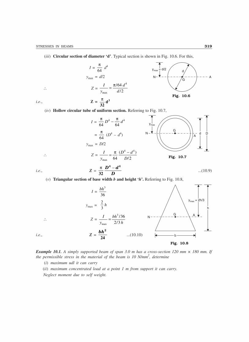
STRESSES IN BEAMS 319
(iii) Circular section of diameter ‘d’. Typical section is shown in Fig. 10.6. For this,
I = π64
d4
ymax = d/2
∴ Z = I
y
d
dmax
/
/= π 64
2
4
i.e., Z = π32
d3
(iv) Hollow circular tube of uniform section. Referring to Fig. 10.7,
I = π π64 64
4 4D d−
= π64
(D4 – d4)
ymax = D/2
∴ Z = I
y
D d
Dmax
( )
/= −π
64 2
4 4
i.e., Z = π32
D dD
4 4−...(10.9)
(v) Triangular section of base width b and height ‘h’. Referring to Fig. 10.8,
I = bh3
36
ymax = 2
3h
∴ Z = I
y
bh
hmax
/
/=
3 36
2 3
i.e., Z = bh2
24...(10.10)
Example 10.1. A simply supported beam of span 3.0 m has a cross-section 120 mm × 180 mm. Ifthe permissible stress in the material of the beam is 10 N/mm2, determine
(i) maximum udl it can carry
(ii) maximum concentrated load at a point 1 m from support it can carry.
Neglect moment due to self weight.
y = d/2maxy = d/2max
N A
d
G
Fig. 10.6
ymaxymax
NG
Add DD
Fig. 10.7
NG
bb
y = 2h/3maxy = 2h/3max
hh
A
Fig. 10.8
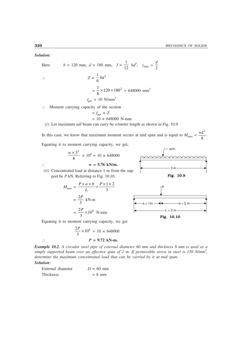
320 MECHANICS OF SOLIDS
Solution:
Here b = 120 mm, d = 180 mm, I = 1
12 bd3, ymax =
d
2
∴ Z = 1
62bd
= 1
6120 1802× × = 648000 mm3
fper = 10 N/mm2
∴ Moment carrying capacity of the section= fper × Z
= 10 × 648000 N-mm(i) Let maximum udl beam can carry be w/metre length as shown in Fig. 10.9.
In this case, we know that maximum moment occurs at mid span and is equal to Mmax = wL2
8.
Equating it to moment carrying capacity, we get,
w × 38
2
× 106 = 10 × 648000
∴ w = 5.76 kN/m.(ii) Concentrated load at distance 1 m from the sup-
port be P kN. Referring to Fig. 10.10.
Mmax = P a b
L
P× × = × ×1 2
3
= 2
3
P kN-m
= 2
3106P × N-mm
Equating it to moment carrying capacity, we get
2
3106P × = 10 × 648000
∴ P = 9.72 kN-m.
Example 10.2. A circular steel pipe of external diameter 60 mm and thickness 8 mm is used as asimply supported beam over an effective span of 2 m. If permissible stress in steel is 150 N/mm2,determine the maximum concentrated load that can be carried by it at mid span.
Solution:External diameter D = 60 mmThickness = 8 mm
Fig. 10.9
Fig. 10.10
w/m
3 m3 m
P
a = 1ma = 1m b = 2 mb = 2 m
L = 3 mL = 3 m
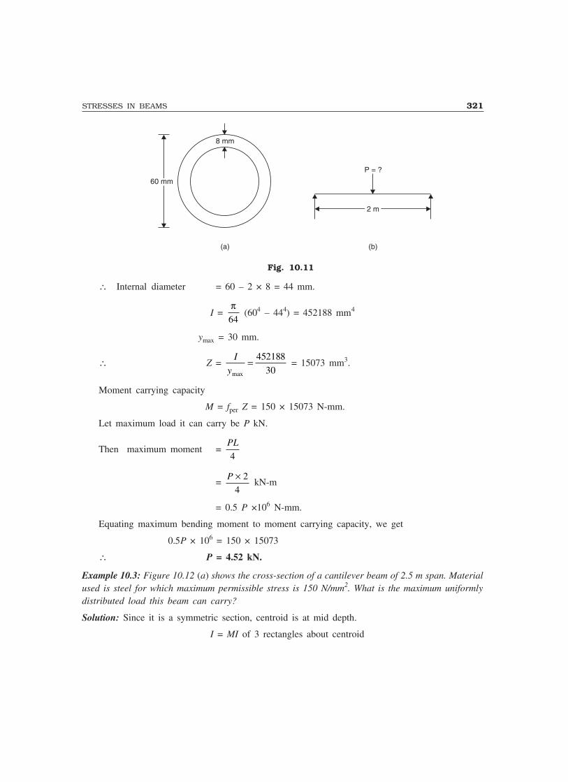
STRESSES IN BEAMS 321
8 mm
60 mm60 mm
P = ?
2 m2 m
(a) (b)
Fig. 10.11
∴ Internal diameter = 60 – 2 × 8 = 44 mm.
I = π64
(604 – 444) = 452188 mm4
ymax = 30 mm.
∴ Z = I
ymax
= 452188
30 = 15073 mm3.
Moment carrying capacity
M = fper Z = 150 × 15073 N-mm.
Let maximum load it can carry be P kN.
Then maximum moment = PL
4
= P × 2
4 kN-m
= 0.5 P ×106 N-mm.
Equating maximum bending moment to moment carrying capacity, we get
0.5P × 106 = 150 × 15073
∴ P = 4.52 kN.
Example 10.3: Figure 10.12 (a) shows the cross-section of a cantilever beam of 2.5 m span. Materialused is steel for which maximum permissible stress is 150 N/mm2. What is the maximum uniformlydistributed load this beam can carry?
Solution: Since it is a symmetric section, centroid is at mid depth.
I = MI of 3 rectangles about centroid

322 MECHANICS OF SOLIDS
180 mm180 mm 10 mm
10 mm
10 mm400 mm400 mm
w/m = ?
2 m2 m
(a) (b)
Fig. 10.12
= 1
12180 103× × + 180 × 10 (200 – 5)2
+ 1
1210 400 20 3× × −( ) + 10 × (400 – 20) × 02
+ 1
12 × 180 × 103 + 180 × 10 (200 – 5)2
= 182.6467 × 106 mm4
[Note: Moment of above section may be calculated as difference between MI of rectangle of size 180 × 400and 170 × 380. i.e.,
I = 1
12 × 180 × 4003 –
1
12170 3803× ×
ymax = 200 mm.
∴ Z = I
ymax
= ×182.6467 10
200
6
= 913233 mm3.
∴ Moment carrying capacity
= fper × Z
= 180 × 913233
= 136985000 N-mm.
If udl is w kN/m, maximum moment in cantilever
= wL = 2w kN-mm
= 2w × 106 N-mm
Equating maximum moment to movement carrying capacity of the section, we get
2w × 106 = 136985000
∴ w = 68.49 kN/m
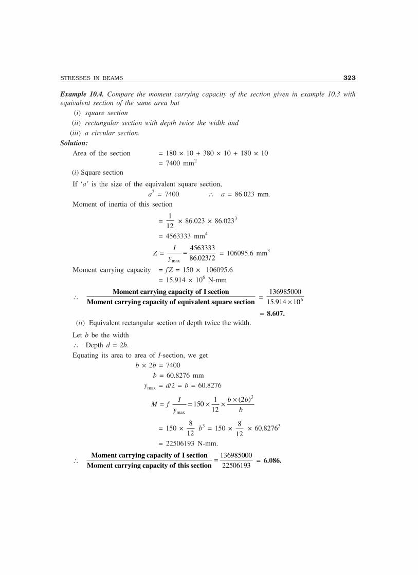
STRESSES IN BEAMS 323
Example 10.4. Compare the moment carrying capacity of the section given in example 10.3 withequivalent section of the same area but
(i) square section
(ii) rectangular section with depth twice the width and
(iii) a circular section.
Solution:Area of the section = 180 × 10 + 380 × 10 + 180 × 10
= 7400 mm2
(i) Square section
If ‘a’ is the size of the equivalent square section,
a2 = 7400 ∴ a = 86.023 mm.Moment of inertia of this section
= 1
12 × 86.023 × 86.0233
= 4563333 mm4
Z = I
ymax . /= 4563333
86 023 2 = 106095.6 mm3
Moment carrying capacity = f Z = 150 × 106095.6
= 15.914 × 10⁶ N-mm
∴Moment carrying capacity of I section
Moment carrying capacity of equivalent square section =
136985000
15.914 106× = 8.607.
(ii) Equivalent rectangular section of depth twice the width.
Let b be the width∴ Depth d = 2b.
Equating its area to area of I-section, we get b × 2b = 7400
b = 60.8276 mm ymax = d/2 = b = 60.8276
M = f I
y
b b
bmax
( )= × × ×150
1
12
2 3
= 150 × 8
12 b3 = 150 ×
8
12 × 60.82763
= 22506193 N-mm.
∴Moment carrying capacity of I section
Moment carrying capacity of this section= 136985000
22506193 = 6.086.

324 MECHANICS OF SOLIDS
(iii) Equivalent circular section.
Let diameter be d.
Then, πd 2
4 = 7400
d = 97.067
I = π
64 d4
ymax = d/2
∴ Z = I
yd
max
= π32
3.
M = fper Z = 150 × π32
× 97.0673 = 13468024
∴ Moment carrying capacity of I sectionMoment carrying capacity of circular section
= 136985000
13468024 = 10.17.
[Note. I section of same area resists more bending moment compared to an equivalent square, rectangular orcircular section. Reason is obvious because in I-section most of the area of material is in heavily stressed zone.]
Example 10.5. A symmetric I-section of size 180 mm × 40 mm, 8 mm thick is strengthened with 240mm × 10 mm rectangular plate on top flange as shown is Fig. 10.13. If permissible stress in thematerial is 150 N/mm2, determine how much concentrated load the beam of this section can carryat centre of 4 m span. Given ends of beam are simply supported.
Solution: Area of section A
= 240 × 10 + 180 × 8 + 384 × 8 + 180 × 8 = 8352 mm2
240 mm240 mm
10 mm
400 mm400 mm
8 mm thick
180 mm180 mm
Fig. 10.13
Let centroid of the section be at a distance y from the bottom most fibre. Then
A y = 240 × 10 × 405 + 180 × 8 × (400 – 4) + 384 × 8 × 200 + 180 × 8 × 4
STRESSES IN BEAMS 325
i.e., 8352 y = 2162400
∴ y = 258.9 mm
I = 1
12 × 240 × 103 + 240 × 10 (405 – 258.9)2
+ 1
12× 180 × 83 + 180 × 8 (396 – 258.9)2
+ 1
12 × 8 × 3843 + 8 × 384 (200 – 258.9)2
+ 1
12180 83× × + 180 × 8 (4 – 258.9)2
= 220.994 × 106 mm4
∴ ytop = 405 – 258.9 = 146.1 mm
ybottom = 258.9 mm.∴ ymax = 258.9 mm
∴ Z = I
ymax
.
.= ×220 994 10
258 9
6
= 853588.3
∴ Moment carrying capacity of the section= fper Z = 150 × 853588.3= 128038238.7 N-mm
= 128.038 kN-m.Let P kN be the central concentrated load the simply supported beam can carry. Then max
bending movement in the beam
= P × 4
4 = P kN-m
Equating maximum moment to moment carrying capacity, we get
P = 128.038 kN.Example 10.6. The cross-section of a cast iron beam is as shown in Fig. 10.14(a). The top flangeis in compression and bottom flange is in tension. Permissible stress in tension is 30 N/mm2 and itsvalue in compression is 90 N/mm2. What is the maximum uniformly distributed load the beam cancarry over a simply supported span of 5 m?
Solution:Cross-section area A = 75 × 50 + 25 × 100 + 150 × 50
= 13750 mm2
Let neutral axis lie at a distance y from bottom most fibre. Then
Ay = 75 × 50 × 175 + 25 × 100 × 100 + 150 × 50 × 25
13750 × y = 1093750
∴ y = 79.54 mm

326 MECHANICS OF SOLIDS
75 mm75 mm
150 mm150 mm
25
50 mm50 mm
50 mm50 mm
100 mm100 mm
–y–y
ft
fc
(a) (b)
Fig. 10.14
∴ I = 1
12 × 75 × 503 + 75 × 50 (175 – 79.54)2
+ 1
12 × 25 × 1003 + 25 × 100 (100 – 79.54)2
+ 1
12 × 150 × 503 + 150 × 50 (25 – 79.54)2
= 61.955493 × 106 mm4.Extreme fibre distances are
ybottom = y = 79.54 mm.
ytop = 200 – y = 200 – 79.54 = 120.46 mm.
Top fibres are in compression. Hence from consideration of compression strength, momentcarrying capacity of the beam is given by
M1 = fper in compression × I
ytop
= 90 × 61955493 10
120
6..46
×
= 46.289178 × 10⁶ N-mm
= 46.289178 kN-m.Bottom fibres are in tension. Hence from consideration of tension, moment carrying capacity of
the section is given by
M2 = fper in tension × I
ybottom

STRESSES IN BEAMS 327
= 30 61.955493 10
79.54
6× ×
= 21.367674 × 10⁶ N-mm
= 21.367674 kN-m.Actual moment carrying capacity is the lower value of the above two values. Hence moment
carrying capacity of the section is= 21.367674 kN-m.
Maximum moment in a simply supported beam subjected to udl of w/unit length and span L is
= wL2
8
Equating maximum moment to moment carrying capacity of the section, we get maximum loadcarrying capacity of the beam as
w × 58
2
= 21.367674
∴ w = 6.838 kN/m.
Example 10.7. The diameter of a concrete flag post varies from 240 mm at base to 120 mm at topas shown in Fig. 10.15. The height of the post is 10 m. If the post is subjected to a horizontal forceof 600 N at top, find the section at which stress is maximum. Find its value also.
Solution: Consider a section y metres from top. Diameter at this section is
d = 120 + y
10 (240 – 120)
= 120 + 12y mm
∴ I = π64
d4
Z = I
dd
/2 323= π
= π32
[120 + 12y]3
At this section, moment is given by M = 600 y N-m
= 600000 y N-mm.Equating moment of resistance to moment at the section, we get
f Z = M
where f is extreme fibre stress
∴ f . π32
[120 + 12y]3 = 600000 y
∴ f = 600000 × 32 y
yπ [ ]120 12 3+
Fig. 10.15
120 mm
240 mm240 mm
10 m10 m
ymym
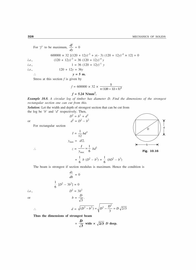
328 MECHANICS OF SOLIDS
For ‘f ’ to be maximum,df
dy = 0
600000 × 32 [(120 + 12y)–3 + y(– 3) (120 + 12y)–4 × 12] = 0i.e., (120 + 12y)–3 = 36 (120 + 12y)–4 y
i.e., 1 = 36 (120 + 12y)–1 y
i.e., 120 + 12y = 36y
∴ y = 5 m.Stress at this section f is given by
f = 600000 × 32 × 5
120 12 5 3π ( )+ ×
f = 5.24 N/mm2.Example 10.8. A circular log of timber has diameter D. Find the dimensions of the strongestrectangular section one can cut from this.
Solution: Let the width and depth of strongest section that can be cut fromthe log be ‘b’ and ‘d’ respectively. Then,
D2 = b2 + d2
or d2 = D2 – b2
For rectangular section
I = 1
123bd
ymax = d/2.
∴ z = I
ymax
= 1
6 bd2
= 1
6 b (D2 – b2) =
1
6 (bD2 – b3)
The beam is strongest if section modulus is maximum. Hence the condition is
dz
db = 0
1
6 [D2 – 3b2] = 0
i.e., D2 = 3b2
or b = D
3.
∴ d = ( ) /D b DD
D2 2 22
32 3− = − =
Thus the dimensions of strongest beam
= D3
wide × 2/3 D deep.
Fig. 10.16
D dd
bb
STRESSES IN BEAMS 329
10.6 PROPORTIONING SECTIONS
In designing beams, span of the beam is known and load expected on the beam can be estimated.Hence bending moment to be resisted by the beam can be calculated. A designer has to select suitablesection of the beam of desirable materials. Theoretically speaking, the section required changes alongthe span. Usually uniform sections are used. Hence the section selected should be capable of resistingthe maximum moment. In case of circular sections we may find the diameter required, since sectionmodulus required depends only on diameter. In case of rectangular sections, section modulus dependsupon width and depth. Hence usually width is assumed and depth is calculated or else ratio of widthto depth is assumed and section is selected. For steel sections, Indian Standard Hand Book may beused to identify standard section that satisfies the required section modulus value. This process ofproportioning sections is known as Design. The design process is illustrated with the followingexamples:Example 10.9. Design a timber beam is to carry a load of 5 kN/m over a simply supported span of6 m. Permissible stress in timber is 10 N/mm2. Keep depth twice the width.
Solution:w = 5 kN/m, L = 6 m.
∴ Maximum bending moment
= wL2 2
8
5 6
8= ×
= 22.5 kN-m
= 22.5 × 10⁶ N-mmLet b be the width and d the depth. Then in this problem d = 2b
∴ Z = 1
6 bd2 =
1
6 × b (2b)2
= 2
3 b3
f = 10 N/mm2 (given)
Hence design requirement isf Z = M
i.e., 10 × 23
b3 = 22.5 × 10⁶
∴ b = 150 mm.
∴ d = 2b = 300 mm.Use 150 mm × 300 mm section.
Example 10.10. A cantilever of 3 m span, carrying uniformly distributed load of 3 kN/m is to bedesigned using cast iron rectangular section. Permissible stresses in cast iron are f = 30 N/mm2 intension and fc = 90 N/mm2 in compression. Proportion the section suitably.
Solution:Span of cantilever = 3 m w = 3 kN/m
∴ Maximum moment = wL2 2
23 3
2= ×
= 13.5 kN-m
= 13.5 × 10⁶ N-mm

330 MECHANICS OF SOLIDS
Let b be the width and d the depth.
∴ Z = 1
6 bd2
Since it is rectangular section, N-A lies at mid-depth, and stresses at top and bottom are same.Hence, permissible tensile stress value is reached earlier and it governs the design.
fper = 30 N/mm2
∴ Design condition is
f Z = M
30 × 1
6 bd2 = 13.5 × 10⁶
bd2 = 2700000
Using b = 100 mm, we get
d2 = 2700000
100
∴ d = 164.3 mm
Use 100 mm wide and 165 mm deep section.
Example 10.11. A circular bar of simply supported span 1 m has to carry a central concentratedload of 800 N. Find the diameter of the bar required, if permissible stress is 150 N/mm2.Solution: Let the diameter of the bar be ‘d’. Now, W = 800 N L = 1 m = 1000 mm.
∴ Maximum moment = WL
4
= 800 1000
4
× = 200000 N-mm
f = 150 N/mm2
Z = π32
d3
∴ Design condition is,
150 × π32
d3 = 200000
∴ d = 23.8 mm
Select 25 mm bar (which is available in market)
10.7 SHEAR STRESS DISTRIBUTION
In the 9th chapter we have seen that in a beam bending moment as well as shearing forces act. Shearforce gives rise to shearing stresses in the beam. In this article expression for shearing stress isderived and its variation across the section is discussed. A designer has to see that the beam is safenot only in bending but in shear also.
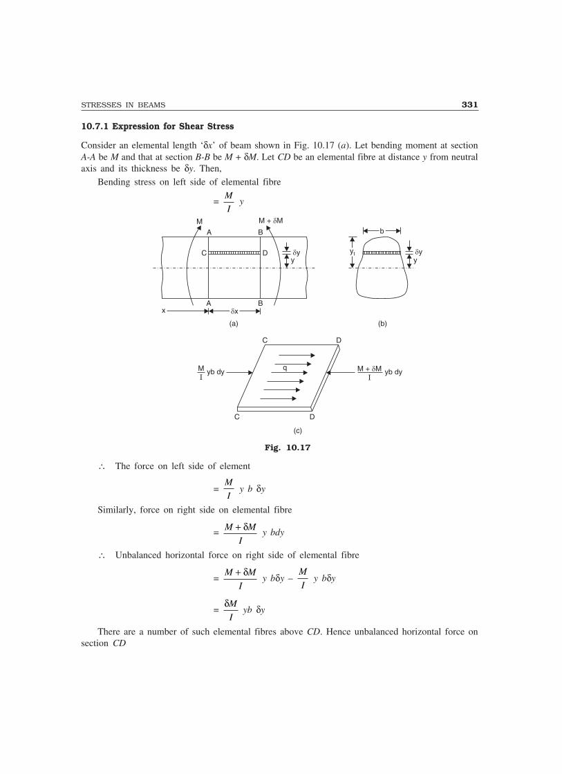
STRESSES IN BEAMS 331
10.7.1 Expression for Shear Stress
Consider an elemental length ‘δx’ of beam shown in Fig. 10.17 (a). Let bending moment at sectionA-A be M and that at section B-B be M + δM. Let CD be an elemental fibre at distance y from neutralaxis and its thickness be δy. Then,
Bending stress on left side of elemental fibre
= M
I y
M
A B
M + M�
C D �yy
A B�x�xx
bb
�yy
ytyt
(a) (b)
C D
q
C D
MI
yb dy M + M�I
yb dy
(c)
Fig. 10.17
∴ The force on left side of element
= M
I y b δy
Similarly, force on right side on elemental fibre
= M M
I
+ δ y bdy
∴ Unbalanced horizontal force on right side of elemental fibre
= M M
I
+ δ y bδy –
M
I y bδy
= δM
I yb δy
There are a number of such elemental fibres above CD. Hence unbalanced horizontal force onsection CD

332 MECHANICS OF SOLIDS
= dM
Iy
yt
� y b δy
= dM
Iy
yt
� y b dy = δM
Iyb dy
y
yt
�Let intensity of shearing stress on element CD be q. [Refer Fig. 10.17 (c)]. Then equating
resisting shearing force to unbalanced horizontal force, we get
q b δx = δM
Iyb dy
y
yt
�
∴ q = δδM
x bIyb dy
y
yt1�
As δx → 0, q = dM
dx bI
1 (a y )
where a y = Moment of area above the section under consideration about neutral axis.
But we knowdMdx
= F
∴ q = FbI
(a y ) ...(10.11)
The above expression gives shear stress at any fibre y distance above neutral axis.
10.7.2 Variation of Shear Stresses Across Standard Sections
Variation of shear stresses across the following three cases are discussed below:(i) Rectangular
(ii) Circular and
(iii) Isosceles triangle.
(i) Rectangular section. Consider the rectangular section of width ‘b’ and depth shown in Fig.10.18(a). Let A-A be the fibre at a distance y from neutral axis. Let the shear force on thesection be F.
Ad/2d/2
d/2d/2
A
y
bb
Parabolicvariation
q = 1.5 qmax av
(a) (b)
Fig. 10.18
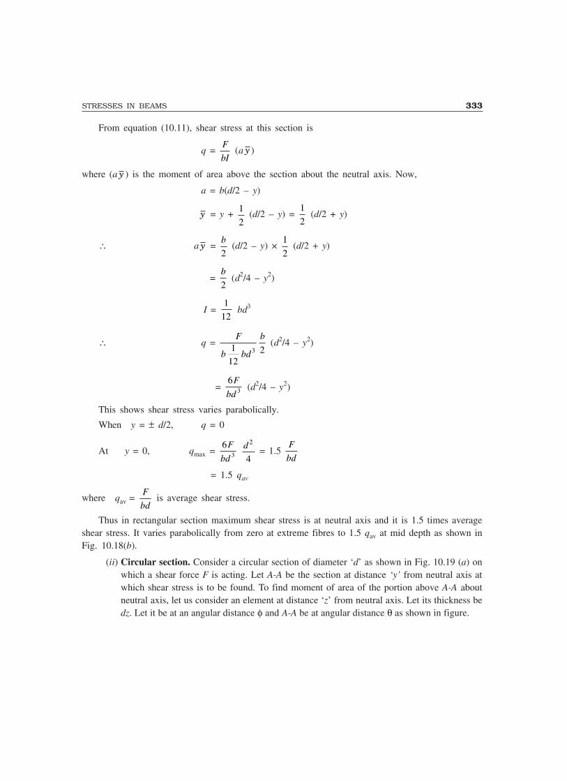
STRESSES IN BEAMS 333
From equation (10.11), shear stress at this section is
q = F
bI (a y )
where (a y ) is the moment of area above the section about the neutral axis. Now,
a = b(d/2 – y)
y = y + 1
2 (d/2 – y) =
1
2 (d/2 + y)
∴ a y = b
2 (d/2 – y) ×
1
2 (d/2 + y)
= b
2 (d2/4 – y2)
I = 1
12 bd3
∴ q = F
b bd
b1
1223
(d2/4 – y2)
= 6
3
F
bd (d2/4 – y2)
This shows shear stress varies parabolically.
When y = ± d/2, q = 0
At y = 0, qmax = 6
3
F
bd
d 2
4 = 1.5
F
bd
= 1.5 qav
where qav = F
bd is average shear stress.
Thus in rectangular section maximum shear stress is at neutral axis and it is 1.5 times averageshear stress. It varies parabolically from zero at extreme fibres to 1.5 qav at mid depth as shown inFig. 10.18(b).
(ii) Circular section. Consider a circular section of diameter ‘d’ as shown in Fig. 10.19 (a) onwhich a shear force F is acting. Let A-A be the section at distance ‘y’ from neutral axis atwhich shear stress is to be found. To find moment of area of the portion above A-A aboutneutral axis, let us consider an element at distance ‘z’ from neutral axis. Let its thickness bedz. Let it be at an angular distance φ and A-A be at angular distance θ as shown in figure.

334 MECHANICS OF SOLIDS
yA�
Z
A
dz
b/2b/2 b/2b/2
dd
Neutralaxis
d/2d/2
d/2d/2
Parabolicvariation
q = 4/3 qmax av
(a) (b)
Fig. 10.19
Width of element b = 2. d
2 cos φ
= d cos φ
z = d
2 sin φ
∴ dz = d
2 cos φ dφ
∴ Area of the element
a = bdz = d cos φ . d
2 cos φ dφ
= d2
2 cos2 φ dφ
Moment of this area about neutral axis = area × z
= d 2
2 cos2 φ dφ d
2 sin φ
= d 3
4 cos2 φ sin φ dφ
∴ Moment of area about section A-A about neutral axis
(a y ) = θ
π/ 2 2
4�d cos2 φ sin φ dφ
= d3 3 2
4 3
−�
��
�
��
cos/
φ
θ
π
[Since if cos φ = t, dt = – sin φ dφ and – t3/3 is integration]

STRESSES IN BEAMS 335
∴ (a y ) = d3
4 3× − +���
���
cos cos2 3
2
π θ
= d
12 cos3 θ
Now I = πd 4
64
∴ q = F
bI (a y )
= F
d d
d
cos θ π64
124
3
× cos3 θ
= 64
12 2
F
dπ cos2 θ
= 16
3
F
dπ 2 [1 – sin2 θ]
= 16
3 2
F
dπ 1
2
2
−�
��
�
���
�
���
y
d /
= 16
31
42
2
2
F
d
y
dπ−�
��
�
��
Hence shear stress varies parabolically.
At y = ± d/2, q = 0
y = 0, q = qmax = 16
3 2
F
dπ
= 4
3 4 2
F
dπ /
= 4
3 Area
F
= 4
3 qav.
where qav = average shear stress.Thus in circular sections also shear stress varies parabolically from zero at extreme edges to the
maximum value of 4
3 qav at mid depth as shown in Fig. 10.19(b).
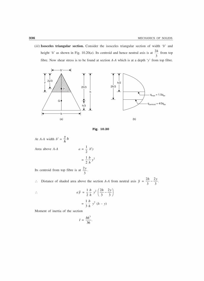
336 MECHANICS OF SOLIDS
(iii) Isosceles triangular section. Consider the isosceles triangular section of width ‘b’ and
height ‘h’ as shown in Fig. 10.20(a). Its centroid and hence neutral axis is at 2
3
h from top
fibre. Now shear stress is to be found at section A-A which is at a depth ‘y’ from top fibre.
bb
2y/32y/3yy
gg
G
bb
2h/32h/3
h/3h/3
hh
2h/32h/3h/2h/2
q = 1.5qmax av
q = 4/3qcentroid av
(a) (b)
Fig. 10.20
At A-A width b′ = yh
b
Area above A-A a = 1
2 b′y
= 1
22b
hy
Its centroid from top fibre is at 2
3
y .
∴ Distance of shaded area above the section A-A from neutral axis y = 2
3
2
3
h y− .
∴ a y = 1
2
b
h y2
2
3
2
3
h y−�
��
= 1
3
b
h y2 (h – y)
Moment of inertia of the section
I = bh3
36.

STRESSES IN BEAMS 337
∴ Shear stress at A-A
q = F
bI a y
= F
yh
bbh
b
h××3
36
1
3 y2 (h – y)
= 12
3
F
bh y(h – y)
Hence at y = 0, q = 0At y = h, q = 0
At centroid, y = 2
3
h
q = 12 2
33
F
bh
h (h – 2h/3)
= 8
3
F
bh =
4
3
F
bh1 2/
= 4
3 qav
where qav is average shear stress.
For qmax, dq
dy = 0
i.e.,12
3
F
bh (h – 2y) = 0
i.e., at y = h/2
and hence qmax = 12
23
F
bh
h. (h – h/2)
= 12
4
3F
bh
F
bh=
= 1 5
1 2
. F
bh/
= 1.5 qav.Thus in isosceles triangular section shear stress is zero at extreme fibres, it is maximum of 1.5
qav at mid depth and has a value 4
3 qav at neutral axis. The variation of shear stress is as shown in
Fig. 10.20(b).

338 MECHANICS OF SOLIDS
10.8 SHEAR STRESSES IN BUILT-UP SECTIONS
In sections like I, T and channel, shear stresses at various salient points are calculated and the shearstress variation diagram across depth is plotted. It may be noted that at extreme fibres shear stressis zero since (a y ) term works out to be zero. However it may be noted that the procedure explainedbelow is for built up section with at least one symmetric axis. If there is no symmetric axis alongthe depth analysis for shear stress is complex, and that is treated beyond the scope to this book.
Example 10.12. Draw the shear stress variation diagram for the I-section shown in Fig. 10.21(a)if it is subjected to a shear force of 100 kN.
180 mm180 mm
10 mm
10 mm
80 mm80 mm
10 mm
400 mm400 mm
19.2171.068
29.10
(a) (b)
Fig. 10.21
Solution: Due to symmetry neutral axis is at mid depth.
I = 1
12 × 180 × 103 + 180 × 10 × (200 – 5)2
+ 1
12 × 10 × 3802 + 10 × 380 × (200 –200)2
+ 1
12 × 180 × 103 + 180 × 10 × (200 – 5)2
= 182.646666 × 106 mm4
Shear stress at y = 200 mm is zero since a y = 0.
Shear stress at bottom of top flange
= F
bI (a y )
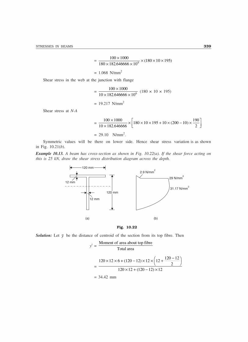
STRESSES IN BEAMS 339
= 100 1000
180 182 646666 10180 10 1956
×× ×
× × ×.
( )
= 1.068 N/mm2
Shear stress in the web at the junction with flange
= 100 1000
10 182 646666 106
×× ×.
(180 × 10 × 195)
= 19.217 N/mm2
Shear stress at N-A
= 100 1000
10 182 646666180 10 195 10 200 10
190
2
××
× × × + × − ×���
���.
( )
= 29.10 N/mm2.
Symmetric values will be there on lower side. Hence shear stress variation is as shownin Fig. 10.21(b).
Example 10.13. A beam has cross-section as shown in Fig. 10.22(a). If the shear force acting onthis is 25 kN, draw the shear stress distribution diagram across the depth.
120 mm120 mm
12 mm
12 mm
120 mm120 mm
2.9 N/mm2
29 N/mm2
31.17 N/mm2
(a) (b)
Fig. 10.22
Solution: Let y be the distance of centroid of the section from its top fibre. Then
yt = Moment of area about top fibre
Total area
= 120 12 6 + (120 12) 12× × − × × + −�
��
× + − ×
12120 12
2120 12 120 12 12( )
= 34.42 mm

340 MECHANICS OF SOLIDS
∴ Moment of inertia about centroid
I = 1
12 × 120 × 123 + 120 × 12 (34.42 – 6)2
+ 1
12 × 12 × 1083 + 12 × 108 34
108
2
2
.42 −�
��
= 2936930 mm4
Shear stresses are zero at extreme fibres.
Shear stress at bottom of flange:
Area above this level, a = 120 × 12 = 1440 mm2
Centroid of this area above N-A
y = 34.42 – 6 = 28.42 mm
Width at this level b = 120 mm.
∴ qbottom of flange = 25 1000
120 2936930
××
× 1440 × 28.42
= 2.90 N/mm2
Shear stress at the same level but in web, where width b = 12 mm
= 25 1000
12 2936930
××
× 1440 × 28.42
= 29.0 N/mm2
Shear stress at neutral axis:
For this we can consider a y term above this section or below this section. It is convenient toconsider the term below this level.
a = 12 × (120 – 34.42) = 1026.96 mm2
The distance of its centroid from N-A
= 120 34
2
− .42 = 42.79 mm.
Width at this section b = 12 mm.
∴ q = 25 1000
12 2936930
××
× 1026.96 × 42.79
= 31.17 N/mm2
Hence variation of shear stress across the depth is as shown in Fig. 10.22(b).
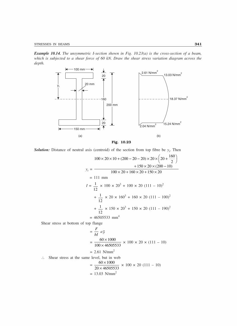
STRESSES IN BEAMS 341
Example 10.14. The unsymmetric I-section shown in Fig. 10.23(a) is the cross-section of a beam,which is subjected to a shear force of 60 kN. Draw the shear stress variation diagram across thedepth.
100 mm100 mm
ytyt20 mm
150 mm150 mm
160160
20
20
200 mm200 mm
2.61 N/mm2
13.03 N/mm2
18.37 N/mm2
15.24 N/mm2
2.04 N/mm2
(a) (b)
Fig. 10.23
Solution: Distance of neutral axis (centroid) of the section from top fibre be yt. Then
yt =
100 20 10 200 20 20 20 20602
150 20 200 10
100 20 160 20 150 20
× × + − − × × + 1�
��
+ × × −× + × + ×
( )
( )
= 111 mm
I = 1
12 × 100 × 203 + 100 × 20 (111 – 10)2
+ 1
12 × 20 × 1603 + 160 × 20 (111 – 100)2
+ 1
12 × 150 × 203 + 150 × 20 (111 – 190)2
= 46505533 mm4
Shear stress at bottom of top flange
= F
bI a y
= 60 1000
100 46505533
××
× 100 × 20 × (111 – 10)
= 2.61 N/mm2
∴ Shear stress at the same level, but in web
= 60 1000
20 46505533
××
× 100 × 20 (111 – 10)
= 13.03 N/mm2

342 MECHANICS OF SOLIDS
Shear stress at neutral axis:
a y = a y of top flange + a y of web above N-A
= 100 × 20 × (111 – 10) + 20 × (111 – 20) × 111 20
2
−
= 284810 mm3.
∴ Shear stress at neutral axis
= F
bI (a y )
= 60 1000
20 46505533
××
× 284810
= 18.37 N/mm2.Shear stress at junction of web and lower flange:
Considering the lower side of the section for finding a y , we get
a y = 150 × 20 × (190 – 111) = 237000 mm3
∴ q = 60 1000
20 46505533
××
× 237000
= 15.28 N/mm2
At the above level but in web, shear stress
= 60 1000
150 46505533
××
× 237000
= 2.04 N/mm2
At extreme fibres shear stress is zero. Hence variation of shear across the depth of the sectionis as shown in Fig. 10.23.
IMPORTANT FORMULAE
1. Bending equation: M
I
f
y
E
R= = .
2. Modulus of section Z = I
ymax
.
3. Moment carrying capacity of section = fper Z.4. Section modulus of various sections:
(i) Rectangular: 1
6 bd2 (ii) Hollow rectangular: 1
6
3 3BD bd
D
−
(iii) Solid circular section: π32
d3 (iv) Hollow circular section: π32
4 4D d
D
−
(v) Solid triangular section: bh2
24
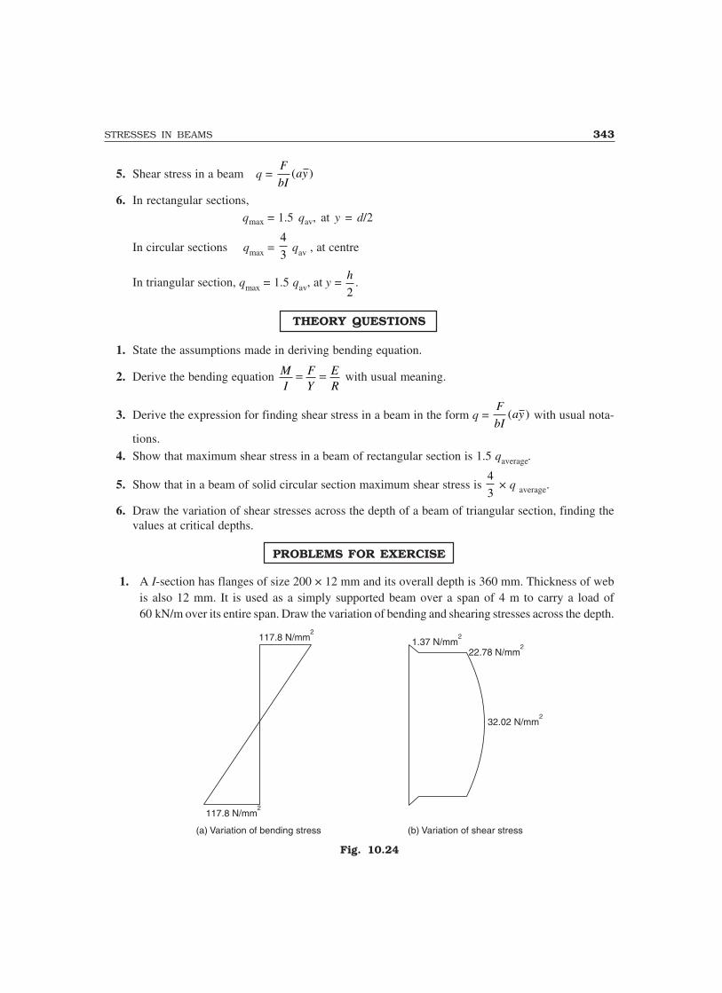
STRESSES IN BEAMS 343
5. Shear stress in a beam q = F
bIay( )
6. In rectangular sections, qmax = 1.5 qav, at y = d/2
In circular sections qmax = 4
3 qav , at centre
In triangular section, qmax = 1.5 qav, at y = h
2.
THEORY QUESTIONS
1. State the assumptions made in deriving bending equation.
2. Derive the bending equation MI
FY
ER
= = with usual meaning.
3. Derive the expression for finding shear stress in a beam in the form q = F
bIay( ) with usual nota-
tions.4. Show that maximum shear stress in a beam of rectangular section is 1.5 qaverage.
5. Show that in a beam of solid circular section maximum shear stress is 4
3 × q average.
6. Draw the variation of shear stresses across the depth of a beam of triangular section, finding thevalues at critical depths.
PROBLEMS FOR EXERCISE
1. A I-section has flanges of size 200 × 12 mm and its overall depth is 360 mm. Thickness of webis also 12 mm. It is used as a simply supported beam over a span of 4 m to carry a load of60 kN/m over its entire span. Draw the variation of bending and shearing stresses across the depth.
117.8 N/mm2
117.8 N/mm2
1.37 N/mm2
22.78 N/mm2
32.02 N/mm2
(a) Variation of bending stress (b) Variation of shear stress
Fig. 10.24
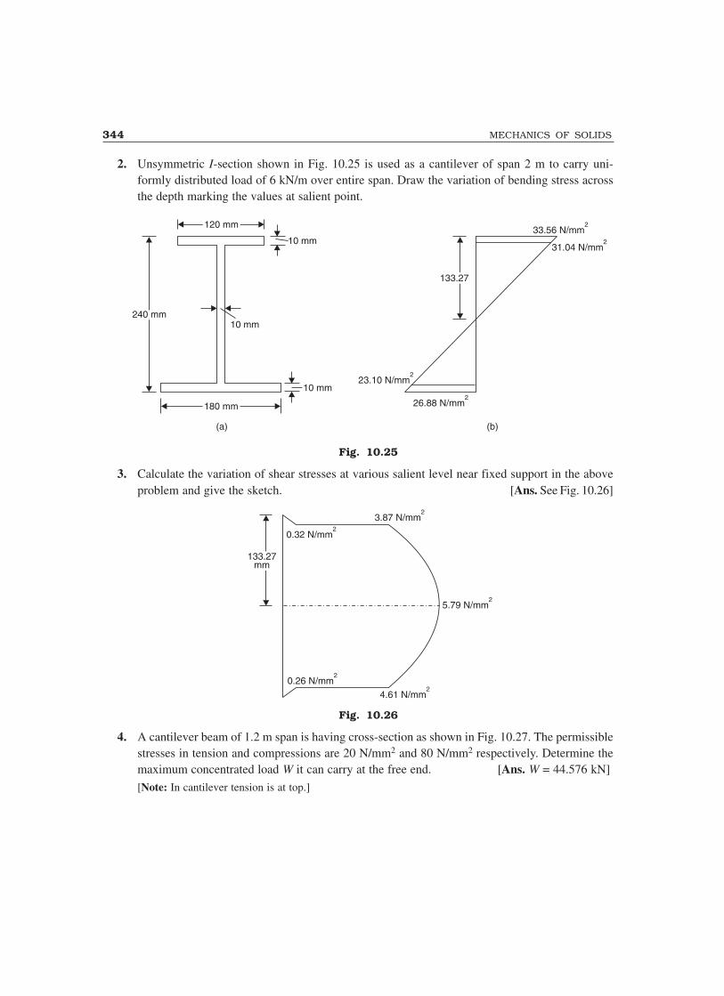
344 MECHANICS OF SOLIDS
2. Unsymmetric I-section shown in Fig. 10.25 is used as a cantilever of span 2 m to carry uni-formly distributed load of 6 kN/m over entire span. Draw the variation of bending stress acrossthe depth marking the values at salient point.
120 mm120 mm
10 mm
10 mm
10 mm
240 mm240 mm
180 mm180 mm
133.27133.27
33.56 N/mm2
31.04 N/mm2
23.10 N/mm2
26.88 N/mm2
(a) (b)
Fig. 10.25
3. Calculate the variation of shear stresses at various salient level near fixed support in the aboveproblem and give the sketch. [Ans. See Fig. 10.26]
0.32 N/mm2
133.27mm
133.27mm
3.87 N/mm2
5.79 N/mm2
0.26 N/mm2
4.61 N/mm2
Fig. 10.26
4. A cantilever beam of 1.2 m span is having cross-section as shown in Fig. 10.27. The permissiblestresses in tension and compressions are 20 N/mm2 and 80 N/mm2 respectively. Determine themaximum concentrated load W it can carry at the free end. [Ans. W = 44.576 kN]
[Note: In cantilever tension is at top.]
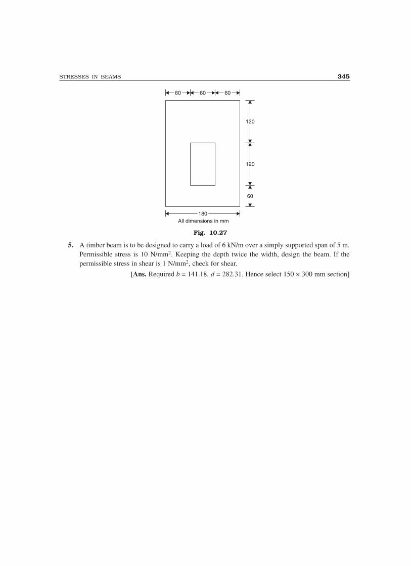
STRESSES IN BEAMS 345
6060 6060 6060
6060
120120
120120
180180All dimensions in mm
Fig. 10.27
5. A timber beam is to be designed to carry a load of 6 kN/m over a simply supported span of 5 m.Permissible stress is 10 N/mm2. Keeping the depth twice the width, design the beam. If thepermissible stress in shear is 1 N/mm2, check for shear.
[Ans. Required b = 141.18, d = 282.31. Hence select 150 × 300 mm section]

11Principal Stresses and Strains
A structural member need not be always under simple (only one type) of stress. It may be subjectedto direct stresses in different directions and may be subjected to shear stresses also. A beam is usuallysubjected to axial stresses due to bending and also for shear stresses. A shaft is subjected to shearstresses due to torsion and axial stresses due to bending/direct thrust. The stresses may vary frompoint to point in the member.
In a three-dimensional system, stresses acting at a point may be represented as shown in Fig. 11.1.
pz
qzx
qzy
qxy
qxz
px
py
qyz
qyx
py
py
pxpx
Fig. 11.1 Fig. 11.2
In many engineering problems, two dimensional idealization is made as shown in Fig. 11.2. Inthis chapter discussion is limited to two dimensional stress system. First general expression forstresses on a plane inclined at a selected axis is discussed. Then the terms principal stresses andplanes are explained and the expressions to get them are presented. A number of problems are solvedto make the concept clear. At the end analysis is given for principal strains also.
11.1 STRESSES ON INCLINED PLANES
Consider the element in a structural member which is under a general two dimensional state of stressas shown in Fig. 11.3(a). Note the sign convention:
+ve face +ve direction is +ve stress for px and py. In other words tensile stresses are +ve.
Shearing stress as shown in the figure is +ve stress.
346

PRINCIPAL STRESSES AND STRAINS 347
py
py
pxpx
q
qBE
C
AO
D
θpx
py
CE
D
θpn
pt
(a) (b)
Fig. 11.3
Now we are interested in finding state of stress on plane DE which makes anticlockwise angleθ with the plane of stress px, in other words with y-axis.
For simplicity let us consider thickness of the element as unity. We are interested in findingnormal and tangential stresses acting on the plane DE. Let normal stress be pn and tangential stresspt as shown in Fig. 11.3(b). Since the system is in equilibrium,
Σ Forces normal to DE = 0 gives pn × DE × 1 = px × CD × 1 × cos θ + q × CD × 1 × sin θ
+ py × CE × 1 × sin θ + q × CE × 1 × cos θ
∴ pn = px CD
DE cos θ + py
CE
DE sin θ + q
CD
DE sin θ + q
CE
DEcos θ
SinceCD
DE = cos θ and
CE
DE = sin θ, we get
pn = px cos2 θ + py sin2 θ + q cos θ sin θ + q sin θ cos θ
= p p qx y1 2
2
1 2
22
+��
��
+ −��
��
+cos cossin cos
θ θ θ θ ,
since cos2 θ = 1 2
2
+ cos θand sin2 θ =
1 2
2
− cos θ
Thus pn = p p p p
qx y x y+
+−
+2 2
2 2cos sinθ θ ...(11.1)
Similarly from equilibrium condition of forces tangential to plane DE, we get
p DEt × × 1 = px × CD × 1 × sin θ – q × CD × 1 × cos θ– py × CE × 1 × cos θ + q × CE × 1 × sin θ
∴ pt = pCD
DEp
CE
DEq
CD
DEq
CE
DEx ysin cos cos sinθ θ θ θ− − +
But CD
DE = cos θ and
CE
DE = sin θ.
∴ pt = px sin θ cos θ – py sin θ cos θ – q cos2 θ + q sin2 θ

348 MECHANICS OF SOLIDS
= (px – py) sin θ cos θ – q(cos2 θ – sin2 θ)
= p p
qx y−−
22 2sin cosθ θ ,
since 2 sin θ cos θ = sin 2θand cos2 θ – sin2 θ = cos 2θ
Thus
pt = p p
qx y−−
22 2sin cosθ θ ...(11.2)
Thus in case of a general two dimension stress system the normal and tangential stresses actingon a plane making anticlockwise angle θ with the plane of px(y direction) are as given by equations(11.1) and (11.2).
Angle of Obliquity of Resultant Stress
The resultant of the stresses on the above inclined plane can be found as
R = p pn t2 2+
which is inclined at ‘α’ to the plane (Ref. Fig. 11.3c).
tan α = p
pn
t
In other words, the resultant is inclined at θ + α to the plane of px.
α
pn
R
pt E Cq
D
py
px
�
Fig. 11.3(c)
11.2 PRINCIPAL STRESSES AND PLANES
The planes on which shearing stresses are zero are called principal planes and the stresses normalto principal planes are known as principal stresses.
Principal Plane
To locate principal plane
pt = 0
From eqn. (11.2), p px y−
2 sin 2θ – q cos 2θ = 0
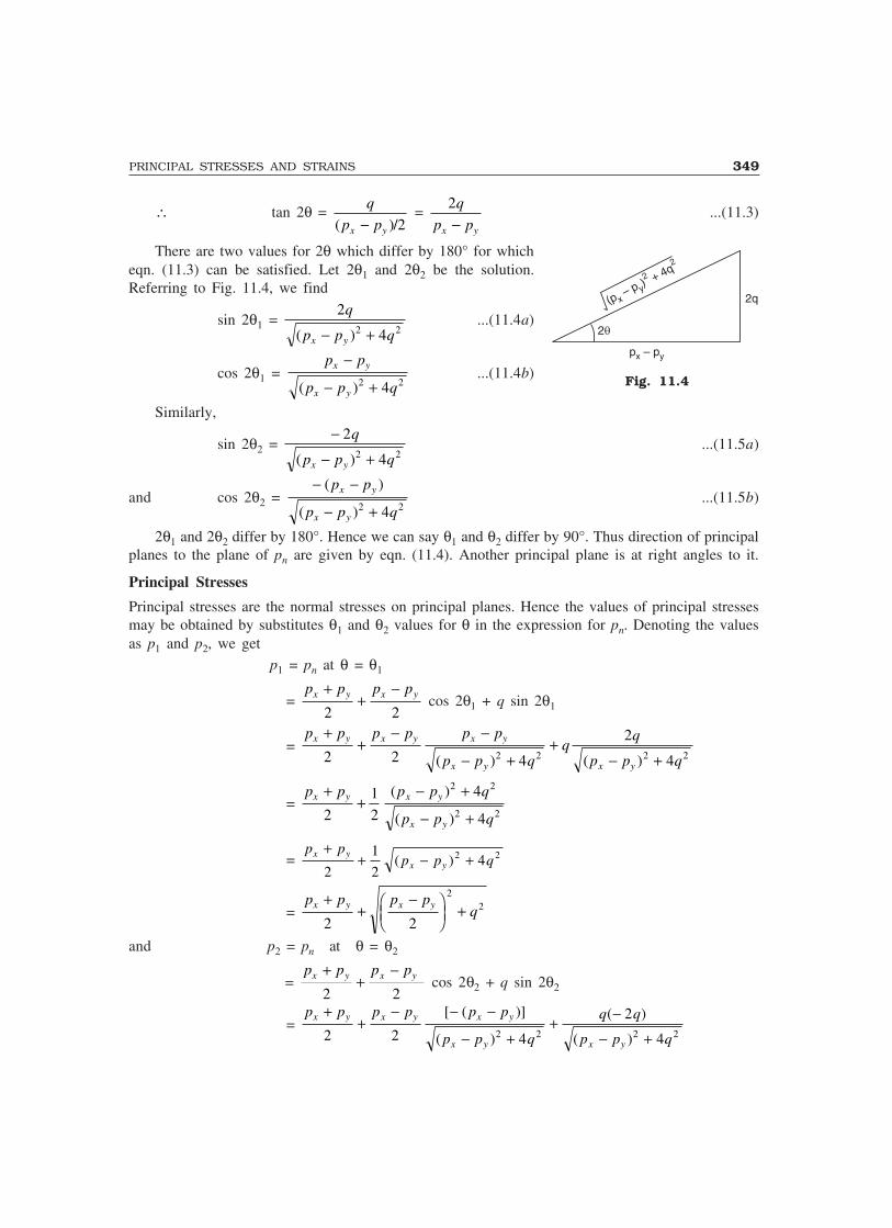
PRINCIPAL STRESSES AND STRAINS 349
∴ tan 2θ = q
p px y( )/− 2 =
2q
p px y−...(11.3)
There are two values for 2θ which differ by 180° for whicheqn. (11.3) can be satisfied. Let 2θ1 and 2θ2 be the solution.Referring to Fig. 11.4, we find
sin 2θ1 = 2
42 2
q
p p qx y( )− +...(11.4a)
cos 2θ1 = p p
p p q
x y
x y
−
− +( )2 24...(11.4b)
Similarly,
sin 2θ2 = −
− +
2
42 2
q
p p qx y( )...(11.5a)
and cos 2θ2 = − −
− +
( )
( )
p p
p p q
x y
x y2 24
...(11.5b)
2θ1 and 2θ2 differ by 180°. Hence we can say θ1 and θ2 differ by 90°. Thus direction of principalplanes to the plane of pn are given by eqn. (11.4). Another principal plane is at right angles to it.
Principal Stresses
Principal stresses are the normal stresses on principal planes. Hence the values of principal stressesmay be obtained by substitutes θ1 and θ2 values for θ in the expression for pn. Denoting the valuesas p1 and p2, we get
p1 = pn at θ = θ1
= p p p px y x y+
+−
2 2 cos 2θ1 + q sin 2θ1
= p p p p p p
p p qq
q
p p q
x y x y x y
x y x y
++
− −
− ++
− +2 2 4
2
42 2 2 2( ) ( )
= p p p p q
p p q
x y x y
x y
++
− +
− +2
1
2
4
4
2 2
2 2
( )
( )
= p p
p p qx y
x y
++ − +
2
1
242 2( )
= p p p p
qx y x y++
−���
���
+2 2
22
and p2 = pn at θ = θ2
= p p p px y x y+
+−
2 2 cos 2θ2 + q sin 2θ2
= p p p p p p
p p q
q q
p p q
x y x y x y
x y x y
++
− − −
− ++ −
− +2 2 4
2
42 2 2 2
[ ( )]
( )
( )
( )
Fig. 11.4
(p– p ) + 4q
xy
2
2
p – px y
2q
2q

350 MECHANICS OF SOLIDS
= p p p p q
p p q
x y x y
x y
+−
− +
− +2
1
2
4
4
2 2
2 2
( )
( )
= p p
p p qx yx y
+− − +
2
1
242 2( )
= p p p p
qx y x y+−
−���
���
+2 2
22
Thus the principal stresses are given by
p1 = p p p p
qx y x y++
−���
���
+2 2
22 ...(11.6a)
and p2 = p p p p
qx y x y+−
−���
���
+2 2
22 ...(11.6b)
It can be proved that principal stresses are maximum and minimum stresses also. To findextreme value of normal stress pn,
dp
dn
θ = 0
i.e.,p px y−
2 2(– sin 2θ) + q 2 cos 2θ = 0
i.e.,p px y−
2 sin 2θ – q cos 2θ = 0
i.e., pt = 0Thus the principal planes are the planes of maximum/minimum normal stresses also. Plane
corresponding to θ1 gives the maximum value while plane corresponding to θ2 gives minimumnormal stress.
Plane of Maximum Shear Stress
For maximum shear
dp
dt
θ θ θ= ′ = 0
i.e.,p px y−
2 . 2 cos 2θ′ – q 2 (– sin 2θ′) = 0
or tan 2θ′ = − −( )p p
qx y
2...(11.7)
From eqn. (11.3) and eqn. (11.7), we get
tan 2θ × tan 2θ′ = –1Hence 2θ′ and 2θ values differ by 90°. In other word planes of extreme shearing stresses are
at 90
2 = 45° to the principal planes.

PRINCIPAL STRESSES AND STRAINS 351
Value of maximum shearing stress may be obtained by substituting θ′ for θ in equation for pt(eqn. 11.2)
Now tan 2θ′ = − −( )p p
qx y
2
From Fig. 11.5, we get
sin 2θ′ = ( )
( )
p p
p p q
x y
x y
−
− +2 24
cos 2θ′ = −
− +
2
42 2
q
p p qx y( )
∴ pt (max) = p px y−
2 sin 2θ′ – q cos 2θ′
= p p p p
p p q
q q
p p q
x y x y
x y x y
− −
− +− −
− +2 4
2
42 2 2 2( )
( )
( )
= 1
2
4
4
2 2
2 2
( )
( )
p p q
p p q
x y
x y
− +
− +
= 1
242 2( )p p qx y− +
= p p
qx y−���
���
+2
22
...(11.8a)
= 1
2 the difference between p1 and p2
= p p1 2
2
−...(11.8b)
The direction of principal planes and the planes of maximum shearing stresses may be indicatedas shown in Fig. 11.6(a) or 11.6(b).
x
qpl
ane
max
qplane
max
p = plane1 y
q45°
45°
45°p -plane2
(a)
x
p2y
(b)
q
p1
q
Fig. 11.6
Fig. 11.5
(p– p ) + 4q
xy
2
2
– 2q
(p – p )x y
2q¢
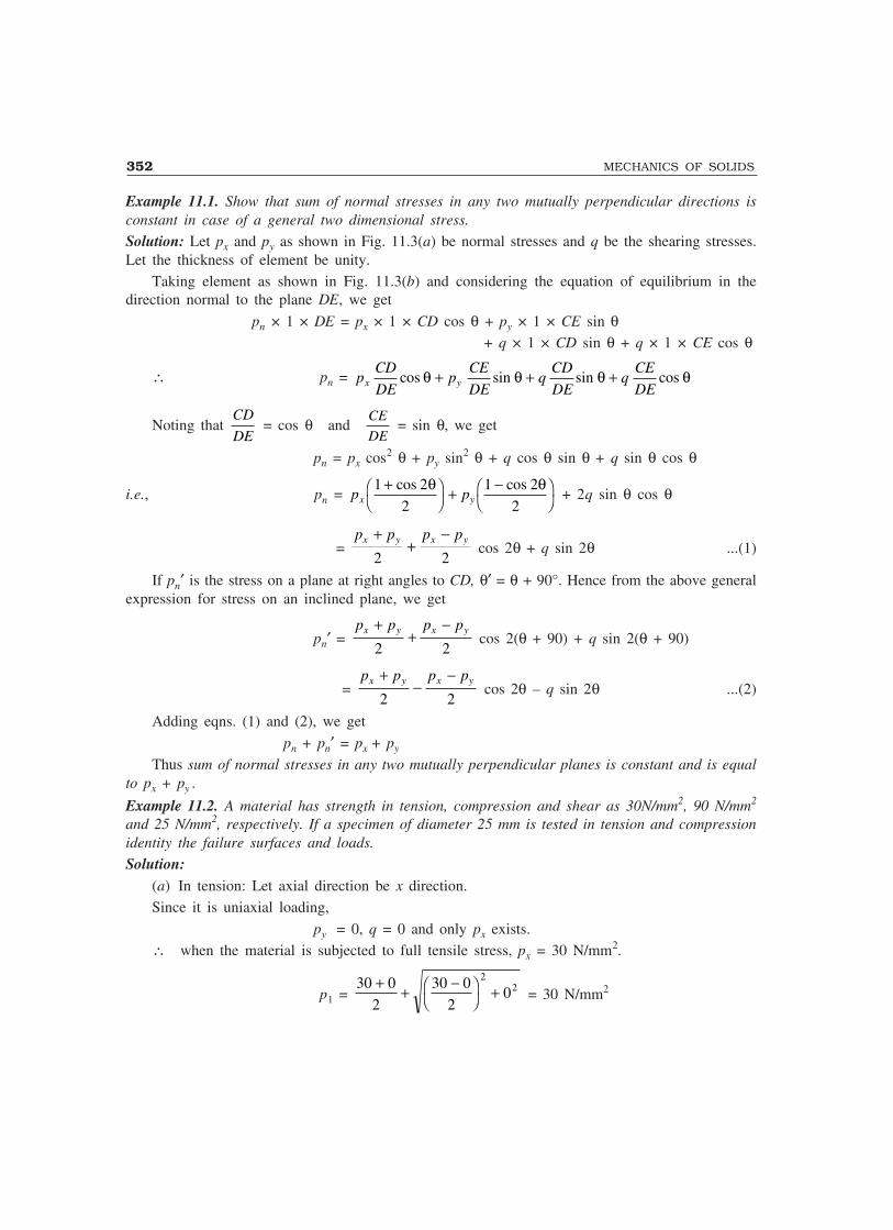
352 MECHANICS OF SOLIDS
Example 11.1. Show that sum of normal stresses in any two mutually perpendicular directions isconstant in case of a general two dimensional stress.
Solution: Let px and py as shown in Fig. 11.3(a) be normal stresses and q be the shearing stresses.Let the thickness of element be unity.
Taking element as shown in Fig. 11.3(b) and considering the equation of equilibrium in thedirection normal to the plane DE, we get
pn × 1 × DE = px × 1 × CD cos θ + py × 1 × CE sin θ + q × 1 × CD sin θ + q × 1 × CE cos θ
∴ pn = pCD
DEp
CE
DEq
CD
DEq
CE
DEx ycos sin sin cosθ θ θ θ+ + +
Noting that CD
DE = cos θ and
CE
DE = sin θ, we get
pn = px cos2 θ + py sin2 θ + q cos θ sin θ + q sin θ cos θ
i.e., pn = p px y1 2
2
1 2
2
+��
��
+ −��
��
cos cosθ θ + 2q sin θ cos θ
= p p p px y x y+
+−
2 2 cos 2θ + q sin 2θ ...(1)
If pn′ is the stress on a plane at right angles to CD, θ′ = θ + 90°. Hence from the above generalexpression for stress on an inclined plane, we get
pn′ = p p p px y x y+
+−
2 2 cos 2(θ + 90) + q sin 2(θ + 90)
= p p p px y x y+
−−
2 2 cos 2θ – q sin 2θ ...(2)
Adding eqns. (1) and (2), we get
pn + pn′ = px + py
Thus sum of normal stresses in any two mutually perpendicular planes is constant and is equalto px + py .
Example 11.2. A material has strength in tension, compression and shear as 30N/mm2, 90 N/mm2
and 25 N/mm2, respectively. If a specimen of diameter 25 mm is tested in tension and compressionidentity the failure surfaces and loads.
Solution:(a) In tension: Let axial direction be x direction.Since it is uniaxial loading,
py = 0, q = 0 and only px exists.∴ when the material is subjected to full tensile stress, px = 30 N/mm2.
p1 = 30 0
2
30 0
20
22+ + −�
���
+ = 30 N/mm2

PRINCIPAL STRESSES AND STRAINS 353
p2 = 30 0
2
30 0
20
22+ − −�
���
+ = 0
qmax = p px y−
= −2
30 0
2 = 15 N/mm2 < 25 N/mm2.
Hence failure criteria is normal stress p1 = 30 N/mm2.Corresponding load P is obtained by
p = P
A
30 = P
( / )π 4 252×or P = 14726 N.
Failure surface is given by plane of p1 which is as shown in Fig. 11.7.
(b) In case of compression test px = – 90 N/mm2, py = q = 0
∴ At failure when px = – 90 N/mm2, load is
– 90 = P
( )π 4 252×or P = – 44178 N i.e., 44178 N compressive.
At this stage qmax = p p
qx y−���
���
+2
22
= − −��
��
+90 0
20
22
= 45 N/mm2 > 25 N/mm2.∴ Material fails because of maximum shear and not by axial
compression.
qmax = p p
qx y−���
���
+2
22
= px −��
��
+0
20
22
= px
2
∴ px = 2qmax = 2 × 25 = 50 N/mm2.∴ Corresponding axial load is given by
50 = P
( )π 4 252×or P = 24543 NThe plane of qmax is at 45° to the plane of px . This failure surface is shown in Fig. 11.8.
Plane of p1
P
P
Fig. 11.7
Failure plane
px
px
45°
Fig. 11.8

354 MECHANICS OF SOLIDS
Example 11.3. The direct stresses at a point in the strained material are 120 N/mm2 compressiveand 80 N/mm2 tensile as shown in Fig. 11.9. There is no shear stress. Find the normal and tangentialstresses on the plane AC. Also find the resultant stress on AC.
30°A B
D C
120 N/mm2
80 N/mm280 N/mm2
120 N/mm2
(a) (b)
A B
Cpn pta
R
80 N/mm2
120 N/mm2
Fig. 11.9
Solution: The plane AC makes 30° (anticlockwise) to the plane of px (y-axis). Hence θ = 30°.
px = 80 N/mm2 py = – 120 N/mm2 q = 0
∴ pn = p p p px y x y+
+−
2 2 cos 2θ + q sin 2θ
= 80 120
2
80 120
2
− + − −( ) cos (2 × 30) + 0
= – 20 + 100 cos 60
Thus pn = 30 N/mm2
pt = p px y−
2 sin 2θ – q cos 2θ
= 80 120
22 30 0
− − × −( )sin ( )
Thus pt = 86.6 N/mm2.
The resultant of pn and pt is given by
p = p pn t2 2+ = 30 86 62 2+ .
p = 91.65 N/mm2
Angle made by the resultant stress with pt is given by tan α = p
pn
t
= 30
86 6.
∴ α = 19.1° as shown in Fig. 11.9(b).

PRINCIPAL STRESSES AND STRAINS 355
Example 11.4. The state of stress at a point in a strained material is as shown in Fig. 11.10. Determine
(i) the direction of principal planes
(ii) the magnitude of principal stresses and
(iii) the magnitude of maximum shear stress.
Indicate the direction of all the above by a sketch.
150 N/mm2
100 N/mm2
200 N/mm2
Fig. 11.10
Solution: px = 200 N/mm2 py = 150 N/mm2 q = 100 N/mm2
Let the principal plane make anticlockwise angle θ with the plane of px i.e. with y-axis. Then
tan 2θ = 2 2 100
200 150
q
p px y−=
×−
= 4
∴ 2θ = 75.96 and 75.96 + 180∴ θθθθθ = 37.98° and 127.98°
p1 = p p p p
qx y x y+
+−�
�����
+2 2
22
= 200 150
2
200 150
2100
22+ + −�
���
+
= 175 + 103.08
p1 = 278.08 N/mm2
and p2 = p p p p
qx y x y+−
−���
���
+2 2
22
∴ p2 = 175 – 103.08 = 71.92 N/mm2.
qmax = p p
qx y−���
���
+2
22
i.e., qmax = 103.08 N/mm2

356 MECHANICS OF SOLIDS
The planes of maximum shear are at 45° to the principal planes. Principal planes and planes ofmaximum shear are shown in Fig. 11.11.
x
qmax plane
qmax plane
p -plane1 y
q45°
45°
45°p - plane2
Fig. 11.11
Example 11.5. The state of stress in a material stressed to two-dimensional state of stress is asshown in Fig. 11.12. Determine principal stresses and maximum shear stress and the planes onwhich they act.
60 N/mm2
20 N/mm2
80 N/mm2
Fig. 11.12
Solution:
p1, 2 = p p p p
qx y x y+±
−���
���
+2 2
22
In this problem,
px = 80 N/mm2 py = – 60 N/mm2 q = 20 N/mm2.
∴ p1, 2 = 80 60
2
80 60
220
22+ − ± − −�
���
+( ) ( )
= 10 70 202 2± +
= 10 ± 72.8
∴ p1 = 82.8 N/mm2

PRINCIPAL STRESSES AND STRAINS 357
and p2 = – 62.8 N/mm2
qmax = p p
qx y−���
���
+2
22
= 72.8 N/mm2
Let θ be the inclination of principal stress to the plane of px. Then,
tan 2θ = 2 2 20
80 60
q
p px y−= ×
− = 2
∴ 2θ = 63.44° or 63.44 + 180
∴ θθθθθ = 31.72° or 121.72°Planes of maximum shear make 45° to the above planes
∴ θ′θ′θ′θ′θ′ = 15.86° and 60.86°
Example 11.6. The state of stress in two-dimensionally stressed body at a point is as shown inFig. 11.13(a). Determine the principal planes, principal stresses, maximum shear stress and theirplanes
75 N/mm2
100 N/mm2
50 N/mm2
Fig. 11.13(a)
Solution: Let x and y directions be selected as shown in the figure. Then
px = – 100 N/mm2, py = – 75 N/mm2, q = – 50 N/mm2
∴ p1 = p p p p
qx y x y++
−���
���
+2 2
22
= − − + − +�
���
+ −100 75
2
100 75
250
22( )
= – 87.5 + 51.54i.e., p1 = – 35.96 N/mm2
p2 = – p p p p
qx y x y+−
−���
���
+2 2
22
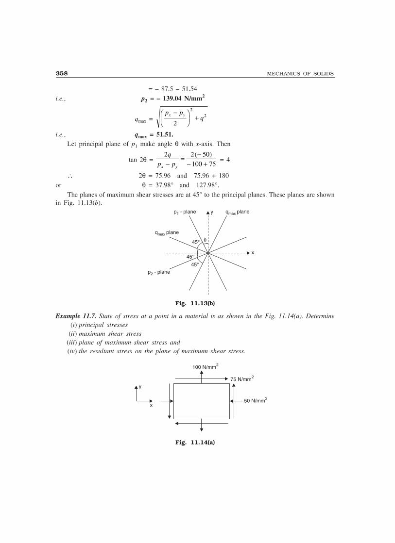
358 MECHANICS OF SOLIDS
= – 87.5 – 51.54
i.e., p2 = – 139.04 N/mm2
qmax = p p
qx y−���
���
+2
22
i.e., qmax = 51.51.Let principal plane of p1 make angle θ with x-axis. Then
tan 2θ = 2 2 50
100 75
q
p px y−= −
− +( )
= 4
∴ 2θ = 75.96 and 75.96 + 180or θ = 37.98° and 127.98°.
The planes of maximum shear stresses are at 45° to the principal planes. These planes are shownin Fig. 11.13(b).
x
qmax plane
qmax plane
p - plane1 y
θ45°
45°
45°p - plane2
Fig. 11.13(b)
Example 11.7. State of stress at a point in a material is as shown in the Fig. 11.14(a). Determine(i) principal stresses
(ii) maximum shear stress(iii) plane of maximum shear stress and(iv) the resultant stress on the plane of maximum shear stress.
75 N/mm2
50 N/mm2
100 N/mm2
x
y
Fig. 11.14(a)

PRINCIPAL STRESSES AND STRAINS 359
Solution: Selecting x and y-axis as shown in figure,
px = – 50 N/mm2, py = 100 N/mm2, and q = 75 N/mm2.
∴ p1 = p p p p
qx y x y+
+−�
�����
+2 2
22
= − + + − −�
���
+50 100
2
50 100
275
22
= 25 + 106.07
= 131.07 N/mm2.
p2 = p p p p
qx y x y+−
−���
���
+2 2
22
= 25 – 106.07
= – 81.07 N/mm2.
qmax = p p
qx y−���
���
+2
22
= 106.07 N/mm2.
The principal plane makes an angle θ to y-axis in anticlockwise direction. Then
tan 2θ = 2 2 75
50 1002
q
p px y−= ×
− −��
��
= – 2
∴ 2θ = – 63.43°or θ = – 31.72° = 31.72° clockwise.
Plane of maximum shear makes 45° to itθ = – 31.72 + 45.00 = 13.28°.
Normal stress on this plane is given by
px = p p p px y x y+
+−
2 2 cos 2θ + q sin 2θ
= − + + − − + ×50 100
2
50 100
22 13 28 75 2 13 28cos ( . ) sin ( . )
= 25 – 67.08 + 33.54
= – 8.54 N/mm2
pt = qmax = 106.07 N/mm2.
∴ Resultant stress p = ( . ) .− +8 54 106 072 2
= 106.41 N/mm2

360 MECHANICS OF SOLIDS
Let ‘p’ make angle φ to tangential stress (maximum shearstress plane). Then referring to Fig. 11.14(b)
tan φ = p
pn
t
= 8 54
106 07
.
.∴ φ = 4.6° as shown in Fig. 11.14(b).
Example 11.8. Show that when a material is subjected to shearingstresses and unidirectional direct stress, the major and minorprincipal stresses are of opposite nature.
Solution: Let px be uniaxial stress
i.e. py = 0Let q be the shearing stresses.
Then from the equation
p1 = p p p p
qx y x y+
+���
���
+−
2 2
22
= p p
qx x
2 2
22+ �
���
+
and p2 = p p
qx x
2 2
22− �
���
+
Since the second term is larger than the first term, naturally p1 is +ve and p2 is –ve. Thus majorand minor principal stresses are having opposite nature.
11.3 PRINCIPAL STRESSES IN BEAMS
Figure 11.15 shows an element of a beam subjected to bending moment and shear force. We know,the bending stress at point A, in the beam,
bending stress px = M
Iy
and shear stress q = F
bIay( )
where M—Bending moment at the section
F—Shear forceI—Moment of inertiay—Distance of the point from neutral axis
b—width
and ay —moment of area above the level of fibre at A about neutral axis.
The state of stress at point A is as shown in the Fig. 11.16 knowing px and q the requiredprincipal stresses, maximum shear stress etc. may be found. The nature of bending stress (tensile orcompressive) should be carefully noted.
Fig. 11.14(b)
13.25°p = 8.54x
4.6°
p =t 106.07
N/mm2

PRINCIPAL STRESSES AND STRAINS 361
M
F
F
N AA
Ay
px
NN AA
q
Fig. 11.15
px px
q
qStresses at point A
Fig. 11.16
Example 11.9. A shear force of 100 kN and a sagging moment of 80 kN-m act at a certain cross-sectionof rectangular beam 100 mm wide and 200 mm deep. Compute the principal stresses at a point 30mm below the top surface.
Solution: Referring to Fig. 11.17,
I = 1
12 × 100 × 2003 = 66.667 × 106 mm4
At point A, which is at 30 mm below top fibrey = 100 – 30 = 70 mm
∴ fx = M
Iy = 80 10
66 667 10
6
6
××.
× 70 = 84 N/mm2 (compressive)
∴ px = – 84 N/mm2
AA
A
100
mm
100
mm
100
mm
100
mm
100 mm
30 mm
yy
N
q
q
84 N/mm2
Fig. 11.17

362 MECHANICS OF SOLIDS
Shearing stress q = F
bIay( )
= 100 10
100 66 667 10
3
6
×× ×.
[100 × 30 × (100 – 15)]
= 3.82 N/mm2 as shown in Fig.
Thus, px = – 84 N/mm2, py = 0, q = 3.82 N/mm2
∴ p1,2 = − + ± − +�
���
+84 0
2
84 0
23 82
22( . )
= – 42 ± 42.17∴ p1 = 0.17 N/mm2
p2 = – 84.17 N/mm2
Example 11.10. A simply supported beam of 4 m span carries loads as shown in Fig. 11.18. Thecross-section of the beam is 100 mm wide and 180 mm deep. At a section 1.5 m from left support,calculate the bending and shearing stresses at distances 0, 45 mm and 90 mm above the neutral axis.Find the principal planes and principal stresses at these points.
1 m1 m 1 m1 m 1 m1 m 1 m1 m
20 kN 20 kN 20 kN
A B
Fig. 11.18
Solution: Due to symmetry,
RA = RB = 20 20 20
2
+ + = 30 kN
∴ At section 1.5 m from A,
F = 30 – 20 = 10 kNM = 30 × 1.5 – 20 × 0.5 = 35 kN-m
I = 1
12 × 100 × 1803 = 48.6 × 106 mm4
∴ Bending stress = f = M
Iy = 35 10
48 6 10
6
6
××.
y
It varies linearly across the depth.when y = 0, f1 = 0
y = 45 mm, f2 = 32.4 N/mm2 (comp).y = 90 mm, f3 = 64.8 N/mm2 (comp).

PRINCIPAL STRESSES AND STRAINS 363
Shearing stress at a fibre ‘y’ above N–A is
q = F
bIay( )
= 10 1000
100 48.6 106
×× ×
( )ay
∴ At y = 0, q1 = 10 1000
100 48.6 106
×× ×
(100 × 90 × 45)
= 0.833 N/mm2
At y = 45 mm, q2 = 10 1000
100 48.6 106
×× ×
100 × 45 × 9045
2−�
���
= 0.625 N/mm2
At y = 90 mm, q3 = 0
The state of stresses on elements under considerations are as shown in Fig. 11.19.
0.833
0.833
32.4 32.4
0.625
0.625
64.8 64.8
(a) At y = 0 (b) At y = 45 mm (c) At y = 90 mm
Fig. 11.19
(a) At neutral axis (y = 0) : The element is under pure shear
px = py = 0 ; q = 0.833 N/mm2
p1, 2 = 0 ± 0 0 8332 2+ ( . ) = ± 0.833 N/mm2
p1 = 0.833 N/mm2
p2 = – 0.833 N/mm2.
Inclination to the plane of px , tan 2θ = 2 0.833×
0 = ∝
∴ 2θ = 90° and 270°∴ θθθθθ = 45° and 135°
(b) At y = 45 mm
px = – 32.4 N/mm2 py = 0, q = 0.625 N/mm2
∴ p1, 2 = − +32.4
2
0 ±
− −��
��
+32.4
20 625
220
.� �
= – 16.2 ± 16.212∴ p1 = 0.012 N/mm2

364 MECHANICS OF SOLIDS
p2 = – 32.412 N/mm2
tan 2θ = 2 0.625
32.4
×− − 0
= 0.09876
2θ = 5.64° and 185.64°
∴ θθθθθ = 2.82° and 92.82°(c) At y = 90 mm,
px = – 64.8 N/mm2, py = 0, q = 0
∴ p1, 2 = − + ± − −�
���
+64.8 0
2
64.8 0
2
220
= – 32.4 ± 32.4
∴ p1 = 0 N/mm2
p2 = – 64.8 N/mm2
tan 2θ = 0 ∴ 2θ = 0° and 180° or θθθθθ = 0° and 90°Example 11.11. A simply supported beam of span 6 m has I-section as shown in Fig. 11.20(a). Itcarries uniformly distributed load (inclusive self weight) of 60 kN/m over entire span. Calculate theprincipal stresses and the maximum shearing stress at 100 mm above neutral axis of the beam ata section 1.5 m from support.
10 mm
10 mm
400
400
10 mm
200200
(a) (b) (c)
Fig. 11.20
Solution: L = 6 m, w = 60 kN/m
∴ Reaction at support = 6 60
2
× = 180 kN
∴ Moment at 1.5 m from support
M = 180 × 1.5 – 60 × 1.5
2
2
= 202.5 kN-m
Shear force at 1.5 m from supportF = 180 – 1.5 × 60 = 90 kN
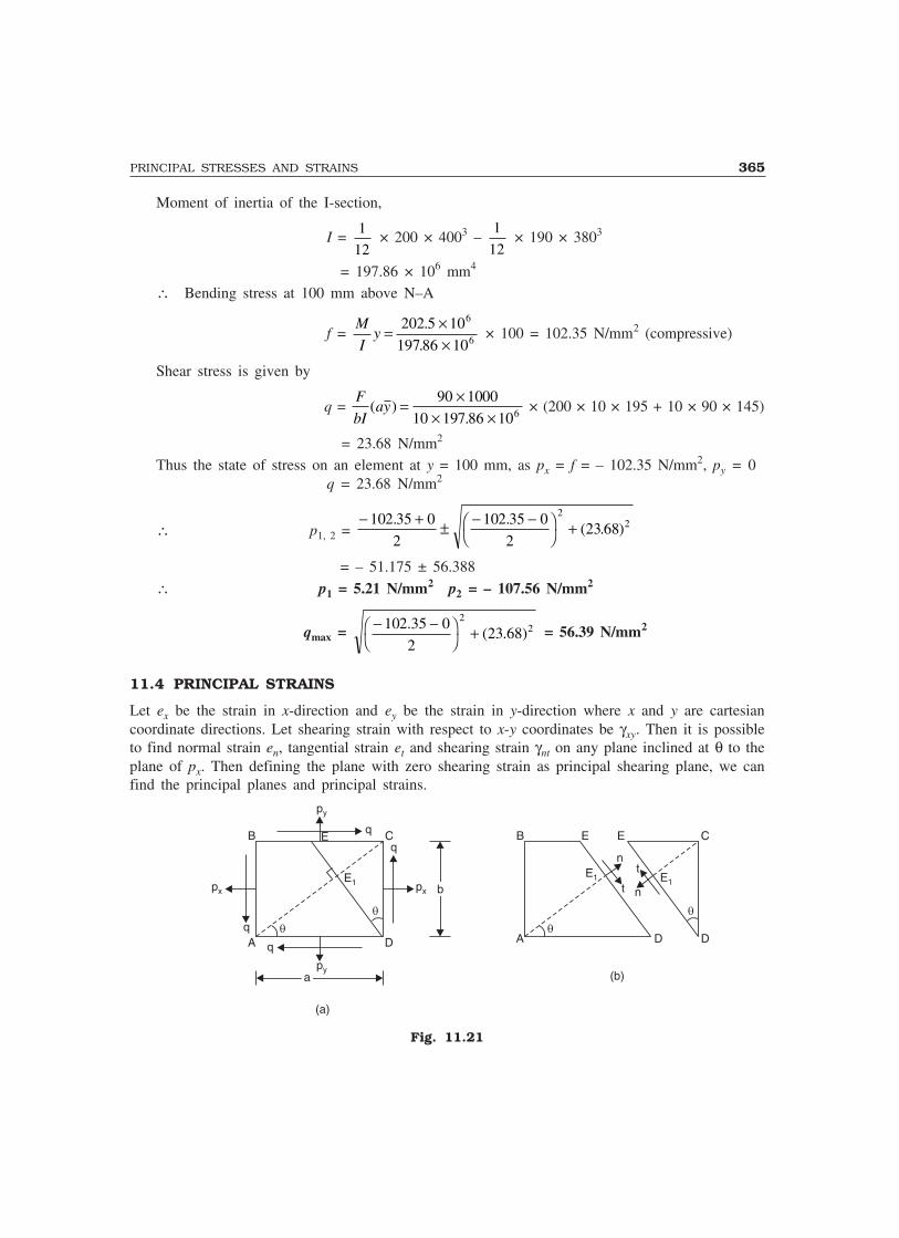
PRINCIPAL STRESSES AND STRAINS 365
Moment of inertia of the I-section,
I = 1
12 × 200 × 4003 –
1
12 × 190 × 3803
= 197.86 × 106 mm4
∴ Bending stress at 100 mm above N–A
f = M
Iy = ×
×202 5 10
197 86 10
6
6
.
. × 100 = 102.35 N/mm2 (compressive)
Shear stress is given by
q = F
bIay( )
.= ×
× ×90 1000
10 197 86 106 × (200 × 10 × 195 + 10 × 90 × 145)
= 23.68 N/mm2
Thus the state of stress on an element at y = 100 mm, as px = f = – 102.35 N/mm2, py = 0q = 23.68 N/mm2
∴ p1, 2 = − + ± − −�
���
+102 35 0
2
102 35 0
223 68
22. .
( . )
= – 51.175 ± 56.388
∴ p1 = 5.21 N/mm2 p2 = – 107.56 N/mm2
qmax = − −��
��
+102.35 0
223.68
22( ) = 56.39 N/mm2
11.4 PRINCIPAL STRAINS
Let ex be the strain in x-direction and ey be the strain in y-direction where x and y are cartesiancoordinate directions. Let shearing strain with respect to x-y coordinates be γxy. Then it is possibleto find normal strain en, tangential strain et and shearing strain γnt on any plane inclined at θ to theplane of px. Then defining the plane with zero shearing strain as principal shearing plane, we canfind the principal planes and principal strains.
(a)
��
B C
A Dq
q
q
q
px px bb
aapy
E
py
E1
��
E E
E1 E1
C
D
n
nt
t
(b)
A
B
D
Fig. 11.21

366 MECHANICS OF SOLIDS
�xy
�
bey
B1 C1
D PD1
aex b�xy
t
CB Q
n
A
E1
Referring to Fig. 11.21(a), which represent state of stress at A with their positive senses it maybe noted that direct strain ex and ey are tensile strains and shearing strain γxy reduces the angle θ.
Figure 11.22 shows the element at A with its de-formed shape (shown with dotted lines) withex,ey and γxy positive. Now we are interested in finding strains en, et and γnt on a plane at ‘θ’ to theplane of px forces. The size of element (a × b) is so selected that the diagonal AE is normal to theplane DE i.e. ∠CAD is also θ, for the convenience.
(a) To find en
Let AC = l,∴ AD = l cos θ = a
AB = l sin θ = b
Drop ⊥ C1, P to AD
⊥ BQ to C1P.
Now,AP = AD + DD1 + D1P
= a + aex + bγxy
= l cos θ + l cos θ × ex + l sin θ × γxy
= l [cos θ + ex cos θ + γxy sin θ] PC = PQ + QC
= b + bey
= l sin θ + l sin θ × ey = l sin θ (1 + ey)
∴ AC1 = AP PC2 2+
= l (cos cos sin ) sin ( )θ θ γ θ θ+ + + × +e ex xy y2 2 21
Neglecting small quantities of higher order,
AC1 = l cos cos sin cos sin sin2 2 2 22 2 2θ θ γ θ θ θ θ+ + + +e ex xy y
= l 1 2 2 2+ + +( cos sin ) sin cose ex y xyθ θ γ θ θ
Expanding by the binomial theorem and neglecting small quantities of order 2 and above, we getAC1 = l [1 + ex cos2 θ + ey sin2 θ + γxy sin θ cos θ]
∴ ex = AC AC
AC1 −
= ex cos2 θ + ey sin2 θ + γxy sin θ cos θ ...(11.9a)
But cos2 θ = 1 2
2
+ cos θ, sin2 θ =
1 2
2
− cos θ
and sin θ cos θ = 1
2 sin 2θ
∴ ex = e e e ex y x y+
+−
2 2 cos 2θ +
1
2 γxy sin 2θ ...(11.9b)
Fig. 11.22
p t

PRINCIPAL STRESSES AND STRAINS 367
Strain et can be found by replacing θ in the above equation by 90 + θ.
∴ et = e e e ex y x y+
−−
2 2 cos 2θ –
1
2 γxy sin 2θ ...(11.10)
To find γnt :
�
beyC1
D PD1
aex b�xy
CB Q
n
A
bb
aa
D2
R
bey
E1 E2
E3
C2C3
Fig. 11.23
After straining let point E1 move to E2. Draw E2R parallel to E1 D [Ref. Fig. 11.23]
∴ Total shearing strain= ∠CAC1 + ∠D1E2R = φ1 + φ2
To find φ1 :Now : CC3 = CC2 sin θ
= (CQ – C2Q) sin θ
= ( )tan
ae b bex xy y+ −�
�
��γ
θ1
sin θ
= (aex + bγxy) sin θ – bey cos θNoting that l cos θ = a and l sin θ = b, we get
CC3 = lex cos θ sin θ + l sin2 θ γxy – ley sin θ cos θ= l (ex – ey) sin θ cos θ + l γxy sin2 θ
∴ φ1 = CC
l3 = (ex – ey) sin θ cos θ + γxy sin2 θ ...(1)
To find φ2 : E3E2 = Extension of AE1
= AE1 en = a cos θ ex = l cos2 θ × ex ...(2)
φ2 = RD
E D
DD RD
E D
DD E E
E D2
1
2 2
1
2 3 2
1
= − = −
= ae l e
ax ncos cos
sin
θ θθ
− 2
= le le
lx ncos cos
sin cos
2 2θ θθ θ−
= (ex – en) cot θ ...(3)
368 MECHANICS OF SOLIDS
Substituting the value of en from eqn. 11.9(a), we get
φ2 = (ex – ex cos2 θ – ey sin2 θ – γxy sin θ cos θ) cot θ= (ex sin2 θ – ey sin2 θ – γxy sin θ cos θ) cot θ= (ex – ey) sin2 θ cot θ – γxy sin θ cos θ cot θ= (ex – ey) sin θ cos θ – γxy cos2 θ ...(4)
∴ γnt = φ1 + φ2
= (ex – ey) sin θ cos θ + γxy sin2 θ + (ex – ey) sin θ cos θ – γxy cos2 θ= 2(ex – ey) sin θ cos θ – γxy (cos2 θ – sin2 θ)
= (ex – ey) sin 2θ – γxy cos 2θ
∴1
2 γnt =
e ex y−2
sin 2θ – 1
2 γxy cos 2θ ...(11.11)
Note. Equation 11.1 is analogous to eqn. 11.9(b) and eqn. 11.2 is analogous to eqn. 11.11 in which p1
or p2 are replaced by e1 and e2 and q has been replaced by 1
2 γxy .
Defining principal strain as the normal strains on the plane where shearing strains is zero, thedirection of principal plane is obtained from 11.11 as
tan 2θ = 2
12
γ γxy
x y
xy
x ye e e e
��
��
−=
−...(11.12)
The magnitude of principal planes may be obtained exactly on the same line as the principalstresses were obtained. The final result will be
e1, 2 = 12
(ex + ey) ± e ex y
xy
−��
���
+ ��
��2
1
2
2 2
γ
= 12
(ex + ey) ± 1
22 2( )e ex y xy− + γ ...(11.13)
The maximum shearing strain occurs at 45° to the plane of principal plane and its magnitude isgiven by
γmax = 1
22 2( )e ex y xy− + γ ...(11.14)
11.5 MEASUREMENT OF STRAIN
Strain is a physical quantity while stress is a concept. Hence it is possible to measure the strains inan experimental investigation. For this electrical strain gauges are used. Electrical strain gaugeconsists of a set of fine wires fixed at a predefined angles and then glued to the experimental model.After loading the model is strained, resulting into changes in the length and diameter of the wire.Hence the resistance of the wire also changes. Electrical strain meters, which work on the principalof Wheatstone Bridge measure the change in resistance and converts it to strains and then displaysthe readings. The set of strain gauges fixed at a point in different direction is called ‘strain rosettes’.

PRINCIPAL STRESSES AND STRAINS 369
Commonly used strain rosettes are 45° rosette and 120° rosette which are as shown in Fig. 11.24.45° rosette is also known as rectangular rosette.
O A
BC
45°
45°
B
A
C
120°
120°
120°
120° 120°60° 60°
60°
A
BC
(a) Rectangular rosette (b) 120° rosette (c) Another form of 120° rosette
Fig. 11.24
Treating one of the strain gauge direction, strains eθ1 and eθ2 of the other two gauges is knownwriting eθ1 and eθ2 in terms of ex, ey and γxy, it is possible to find ex,,ey and γxy.
After finding ex, ey and γxy it is possible to find the corresponding stresses. We know,
Ee1 = p1 – µp2 ...(1)Ee2 = p2 – µp1 ...(2)
Multiplying Eqn. (2) with µ and adding it to eqn.1, we get,E(e1 + µe2) = p1 – µ2p1 = p1(1 – µ2)
∴ p1 = E e e( )1 2
21
+−
µµ
...(11.15a)
Similarly p2 = E e e( )2 1
21
+−
µµ
...(11.15b)
Example 11.12. At a point strains measured with rectangular rosettes are eA = 600 microns, eB =300 microns and ec = – 200 microns. Determine the principal strains. Find principal stresses alsotaking E = 2 × 10⁵ and µ = 0.3.
Solution: Taking the direction of strain gauge as x-axis,ex = 600 microns
eB = e45 = 300 microns and ec = e90 = – 200 microns = ey
∴ 300 = 1
2 (ex + ey) +
1
2 (ex – ey) cos 2 × 45 +
1
2 γxy sin 2 × 45
= 1
2 (600 – 200) +
1
2 (600 + 200) × 0 +
1
2 γxy
γxy = 200 microns.
∴ Principal strains are
e1, 2 = 1
2 (ex + ey) ± e ex y
xy
−��
���
+ ��
��2
1
2
2 2
γ

370 MECHANICS OF SOLIDS
= 1
2(600 – 200) ± 600 200
2
1
2200
2 2+��
��
+ ��
��
= 200 ± 412.3∴ e1 = 612.3 micron = 612.3 × 10⁻⁶
e2 = – 212.3 micron = – 212.3 × 10⁻⁶
[Note: 1 micron = 1 × 10⁻⁶]
∴ p1 = E e e( )1 2
21
+−
= × − × ×−
−µµ
2 10 (612.3 0.3 212.3) 10
1 0.3
5 6
2
i.e., p1 = 120.57 N/mm2.
p2 = E e e( )2 1
21
+−
= × − + ×−
µµ
2 10 ( 212.3 0.3 612.3)
1 0.3
5
2
i.e., p2 = – 6.29 N/mm2
Example 11.13. In an experimental investigation strains observed with a 120° rosette are, e0 = 800microns, e120 = – 600 microns and e240 = 100 microns. Determine the principal stresses, if E = 2 × 10⁵
N/mm2 and µ = 0.3.
Solution: ex = 800
– 600 = e120 = e e e ex y x y+
+−
2 2 cos 240 +
1
2 γxy sin 240
i.e., – 600 = e e e ex y x y+
−−
2 2 (0.5) –
0 866
2
. γxy ...(1)
100 = e240 = e e e ex y x y+
+−
2 2 cos 480 +
1
2 γxy sin 480
∴ 100 = e e e ex y x y+
−−
2 2 (0.5) +
0 866
2
. γxy ...(2)
Adding eqns. (1) and (2), we get
– 500 = ex + ey – e ex y−
2
i.e., – 1000 = ex + 3ey
But ex = 800 microns
∴ 3ey = – 1000 – 800 = – 1800∴ ey = – 600 microns
Substituting the values of ex and ey in eqn. (2), we get
100 = 800 600
2
800 600
2
− − + (0.5) +
0 866
2
. γxy
γxy = 808.3 microns

PRINCIPAL STRESSES AND STRAINS 371
Thus ex = 800 microns, ey = – 600 micron and γxy = 808.3 microns
∴ e1, 2 = e e e ex y x y
xy
+±
−��
���
+ ����2 2
1
2
2 2
γ
= 800 600
2
800 600
2
1
2808 3
2 2− ± +��
��
+ ��
��
.
= 100 ± 808.29
∴ e1 = 908.29 microns = 908.29 × 10⁻⁶
and e2 = – 708.29 microns = – 708.29 × 10⁻⁶
∴ p1 = E e e( )1 2
21
+−
= × − × ×−
−µµ
2 10 (908.29 0.3 708.29) 10
1 0.3
5 6
2
i.e., p1 = 152.9 N/mm2
p2 = E e e( )1 1
21
+−
= × − × ×−
−µµ
2 10 ( 708.29 + 0.3 908.29) 10
1 0.3
5 6
2
i.e., p2 = – 95.8 N/mm2
IMPORTANT FORMULAE
1. pn = p p p px y x y+
+−
2 2 cos 2θ + q sin 2θ.
2. pt = p px y−
2 sin 2θ – q cos 2θ.
3. Principal planes are given by
tan 2θ = 2q
p px y−.
4. p1, 2 = p p p p
qx y x y+±
−��
���
+2 2
22
.
5. Maximum shear stress = p p p p
qx y1 22
2
2 2
− =−�
� ���
+ .
6. Plane of maximum shear is at 45° to the principal planes.7. Obliquity of resultant stress on a plane at θ to the plane of px
= θ + α to the plane of px
where α = tan–1 p
pn
t
.

372 MECHANICS OF SOLIDS
8. en = e e e ex y x y+
+−
2 2 cos 2θ +
1
2 γxy sin 2θ
1
2 rnt =
( )e ex y−2
sin 2θ – 1
2γ xy
cos 2θ
e1, 2 = 1
2(ex + ey) ± e ex y
xy
−��
���
+ ��
��2
1
2
2 2
γ
γmax = e e e ex y
xy1 2
2 2
2 2
1
2
− =−�
� ���
+ ��
��
γ .
THEORY QUESTIONS
1. Derive the expressions for normal and tangential stresses on a plane inclined at θ to the plane ofpx force. Take a general two dimensional state of stress.
2. State the equations for normal and tangential stresses on an inclined plane, in an element undergeneral two dimensional stress system. Derive the expressions for principal planes, principalstresses and maximum shear stress.
3. Explain the terms principal stresses and principal strains.
PROBLEMS FOR EXERCISE
1. A point in a strained material is subjected to tensile stresses px = 180 N/mm2 and py = 120 N/mm2.Determine the intensities of normal, tangential and resultant stresses on a plane inclined at 30°
anticlockwise to the axis of minor stress.
[Note : Axis of minor stress means the plane of major stress]
[Ans. pn = 165 N/mm2, pt = 25.98 N/mm2, p = 167.03 N/mm2, α = 111.05° anticlockwise to theaxis of minor principal plane]
2. The state of stress at a point in a strained material is as shown in Fig. 11.25. Determine thenormal, tangential and the resultant stress on plane DE. Determine the direction of resultant also.
40 N/mm2
C
120 N/mm2
D
B
A
E
60°
Fig. 11.25
[Ans. pn = 0, pt = 69.28 N/mm2, p = 69.28 N/mm2 acts tangential to DE.]

PRINCIPAL STRESSES AND STRAINS 373
3. The state of stress at a point is as shown in Fig. 11.26. Determine the principal stresses andmaximum shear stress. Indicate their planes on a separate sketch.
[Ans. p1 = 133.13 N/mm2, p2 = – 93.13 N/mm2, qmax = 113.13 N/mm2, θ = – 22.5° and 67.5°,θ′ = 22.5 and 112.5°]
100 N/mm2
60 N/mm2
80 N/mm2
(a)
x-axis
p - plane1
qmax plane
q - planemaxy-axis
45°
45°
45°
p - plane2
(b)
22.5
°
Fig. 11.26
4. The state of stress in a two dimensionally stressed material is as shown in Fig. 11.27. Determinethe principal stresses, principal planes and the maximum shear stress. Determine normal andtangential stresses on plane AC also.
60 N/mm2
A
80 N/mm2
C 60 N/mm2
60°
Fig. 11.27
[Ans. p1 = – 9.18 N/mm2, p2 = – 130.82 N/mm2, qmax = 60.82 N/mm2, θ = – 40.27° and 49.73°,pn = – 116.96 N/mm2, pt = 21.34 N/mm2]


![Mechanics of Solids [3 1 0 4] CIE 101 / 102 First Year B.E ...icasfiles.com/mechanics of solids/notes/slides/1... · Mechanics of Solids PART-I PART-II Mechanics of Deformable Bodies](https://static.fdocuments.in/doc/165x107/60e4e466746b7501e128b225/mechanics-of-solids-3-1-0-4-cie-101-102-first-year-be-of-solidsnotesslides1.jpg)


