Strategic Regional Arterials - idot.illinois.gov · Strategic Regional Arterials ... Because SRA...
65
BUREAU OF DESIGN AND ENVIRONMENT MANUAL Chapter Forty-six STRATEGIC REGIONAL ARTERIALS (New Construction/Reconstruction)
Transcript of Strategic Regional Arterials - idot.illinois.gov · Strategic Regional Arterials ... Because SRA...
BUREAU OF DESIGN AND ENVIRONMENT MANUAL
Chapter Forty-six
STRATEGIC REGIONAL ARTERIALS
(New Construction/Reconstruction)


Illinois STRATEGIC REGIONAL ARTERIALS September 2010
46-i HARD COPIES UNCONTROLLED
Chapter Forty-six STRATEGIC REGIONAL ARTERIALS (New Construction/Reconstruction)
Table of Contents
Section Page 46-1 GENERAL ............................................................................................................. 46-1.1
46-1.01 Objectives for a SRA System ............................................................... 46-1.1 46-1.02 SRA Route Definitions.......................................................................... 46-1.2 46-1.03 Spacing of SRA’s ................................................................................. 46-1.2 46-1.04 Coordination with Local Land Use Plans .............................................. 46-1.2 46-1.05 SRA Planning ....................................................................................... 46-1.3
46-1.05(a) Objectives ..................................................................... 46-1.3 46-1.05(b) Implementation Process ................................................ 46-1.3
46-2 URBAN SRA ROUTES .......................................................................................... 46-2.1
46-2.01 General Roadway Features.................................................................. 46-2.1 46-2.02 Geometric Design Elements ................................................................. 46-2.1
46-2.02(a) Median Type ................................................................. 46-2.1 46-2.02(b) Additional Lanes ........................................................... 46-2.1 46-2.02(c) Horizontal and Vertical Clearances ............................... 46-2.4
46-2.03 Access Management ............................................................................ 46-2.4 46-2.04 Intersections ......................................................................................... 46-2.5 46-2.05 Railroad Grade Separations ................................................................. 46-2.7 46-2.06 Interchanges ........................................................................................ 46-2.7 46-2.07 Drainage .............................................................................................. 46-2.7 46-2.08 Removal of On-Street Parking .............................................................. 46-2.7 46-2.09 Traffic Control Devices ......................................................................... 46-2.8
46-2.09(a) Traffic Signals ............................................................... 46-2.8 46-2.09(b) Stop Sign Removal ....................................................... 46-2.9 46-2.09(c) Pavement Markings ...................................................... 46-2.9 46-2.09(d) Driver Information Systems ........................................... 46-2.9
46-2.10 Trucks .................................................................................................. 46-2.9 46-2.11 Transit .................................................................................................. 46-2.9
46-2.11(a) Improvements ............................................................... 46-2.9 46-2.11(b) Local Bus Service ......................................................... 46-2.10 46-2.11(c) HOV Lanes ................................................................... 46-2.10
46-2.12 Pedestrians and Bicyclists .................................................................... 46-2.13 46-2.13 Environmental Considerations .............................................................. 46-2.13

Illinois STRATEGIC REGIONAL ARTERIALS September 2010
46-ii HARD COPIES UNCONTROLLED
Table of Contents (Continued)
Section Page
46-2.14 Right-of-Way ........................................................................................ 46-2.13 46-2.15 Tables of Design Criteria ...................................................................... 46-2.13
46-3 SUBURBAN SRA ROUTES .................................................................................. 46-3.1
46-3.01 General Roadway Features.................................................................. 46-3.1
46-3.01(a) General ......................................................................... 46-3.1 46-3.01(b) Bypass Facilities ........................................................... 46-3.1
46-3.02 Geometric Design Elements ................................................................. 46-3.1
46-3.02(a) Median Types ............................................................... 46-3.1 46-3.02(b) Additional Lanes ........................................................... 46-3.6 46-3.02(c) Vertical Clearances ....................................................... 46-3.6
46-3.03 Access Management ............................................................................ 46-3.6 46-3.04 Intersections ......................................................................................... 46-3.8 46-3.05 Railroad Grade Separations ................................................................. 46-3.9 46-3.06 Interchanges ........................................................................................ 46-3.10 46-3.07 Drainage .............................................................................................. 46-3.10 46-3.08 Removal of On-Street Parking .............................................................. 46-3.10 46-3.09 Traffic Control Devices ......................................................................... 46-3.11
46-3.09(a) Traffic Signals ............................................................... 46-3.11 46-3.09(b) Warrants for Traffic Signals ........................................... 46-3.11 46-3.09(c) Overhead Signing ......................................................... 46-3.11 46-3.09(d) Stop Sign Removal ....................................................... 46-3.11 46-3.09(e) Pavement Markings ...................................................... 46-3.12 46-3.09(f) Driver Information Systems ........................................... 46-3.12
46-3.10 Trucks .................................................................................................. 46-3.12 46-3.11 Transit .................................................................................................. 46-3.12
46-3.11(a) Improvements ............................................................... 46-3.12 46-3.11(b) Express Bus Service ..................................................... 46-3.13
46-3.12 HOV Lanes .......................................................................................... 46-3.13 46-3.13 Pedestrians and Bicyclists .................................................................... 46-3.13 46-3.14 Environmental Considerations .............................................................. 46-3.13 46-3.15 Right-of-Way Acquisition and Corridor Protection ................................. 46-3.14 46-3.16 Tables of Design Criteria ...................................................................... 46-3.14

Illinois STRATEGIC REGIONAL ARTERIALS September 2010
46-iii HARD COPIES UNCONTROLLED
Table of Contents (Continued)
Section Page 46-4 RURAL SRA ROUTES .......................................................................................... 46-4.1
46-4.01 General Roadway Features.................................................................. 46-4.1
46-4.01(a) General ......................................................................... 46-4.1 46-4.01(b) Bypass Facilities ........................................................... 46-4.1
46-4.02 Geometric Design Elements ................................................................. 46-4.1
46-4.02(a) Median Types ............................................................... 46-4.1 46-4.02(b) Additional Lanes ........................................................... 46-4.4 46-4.02(c) Vertical Clearances ....................................................... 46-4.4
46-4.03 Access Management ............................................................................ 46-4.4 46-4.04 Intersections ......................................................................................... 46-4.5 46-4.05 Railroad Grade Separations ................................................................. 46-4.6 46-4.06 Interchanges ........................................................................................ 46-4.6 46-4.07 Drainage .............................................................................................. 46-4.6 46-4.08 Frontage Roads ................................................................................... 46-4.7 46-4.09 Traffic Control Devices ......................................................................... 46-4.7
46-4.09(a) Traffic Signals ............................................................... 46-4.7 46-4.09(b) Overhead Signing ......................................................... 46-4.7 46-4.09(c) Stop Sign Removal ....................................................... 46-4.7 46-4.09(d) Pavement Markings ...................................................... 46-4.7
46-4.10 Transit .................................................................................................. 46-4.8
46-4.10(a) Improvements ............................................................... 46-4.8 46-4.10(b) Express Bus Service ..................................................... 46-4.8
46-4.11 Pedestrians and Bicyclists .................................................................... 46-4.8 46-4.12 Environmental Considerations .............................................................. 46-4.8 46-4.13 Right-of-Way ........................................................................................ 46-4.8 46-4.14 Tables of Design Criteria ...................................................................... 46-4.8
46-5 REFERENCES ...................................................................................................... 46-5.1


Illinois STRATEGIC REGIONAL ARTERIALS September 2010
46-1.1 HARD COPIES UNCONTROLLED
Chapter Forty-six STRATEGIC REGIONAL ARTERIALS (New Construction/Reconstruction)
Strategic Regional Arterials (SRA’s) are a network of highways designed to accommodate long-distance regional traffic, to complement a region’s major transit and highway facilities, and to supplement the freeway system. The Department’s SRA concept was originally developed for Northeastern Illinois and is presented in the IDOT publication Strategic Regional Arterial Design Concept Report “Operation Green Light.” However, this concept could apply to other cities and regions throughout the State.
Many of the Department’s existing arterials can be incorporated into a SRA system. SRA’s may have widely varying characteristics. Existing rights-of-way, roadway features, land use, and access differ from route to route, and also may change from one segment of a route to another. Chapter 46 provides guidance in the planning and design of strategic regional arterials including specific design criteria and techniques encountered on SRA routes, which should be applied throughout the system. Information also applicable to SRA’s is included in the following chapters:
• Chapters 31, 32, 33, 34, and 39 provide guidance on the geometric design elements that are applicable to SRA’s.
• Chapter 36 provides information on the design of intersections including left- and right-turn lanes, channelization, and intersection sight distance.
• Chapter 37 discusses the type, location, and design of interchanges.
• Chapter 38 provides guidelines on roadside safety.
46-1 GENERAL
46-1.01 Objectives for a SRA System
The SRA System is designed to:
• improve regional mobility by providing a comprehensive network of arterial routes designed to carry significant volumes of long distance traffic across a region,
• complement a region’s major transit and highway facilities by providing access for regional trips on these facilities, and
• supplement the regional freeway system.

Illinois STRATEGIC REGIONAL ARTERIALS September 2010
46-1.2 HARD COPIES UNCONTROLLED
46-1.02 SRA Route Definitions
Within the overall SRA network, there are significant differences in the roadway environment that determine how the different types of routes (urban, suburban, and rural) may function in the system. The information in Chapter 46 has been segregated accordingly. For SRA application, the following defines the characteristics for these designations:
1. Urban Routes. Urban areas are defined as those with densities over 5 households per acre (12 households per hectare) in the design year. SRA routes located in densely urbanized areas typically are existing facilities with minimal potential for roadway expansion. However, improvements can be made to intersections, local transit facilities, and low structural clearances.
2. Suburban Routes. Suburban areas are defined as those with densities between 0.5 to 5 households per acre (1 and 12 households per hectare) in the design year. For routes in developing suburban areas, the major concerns are preservation of right-of-way, additional lanes on roadways, new connections to improve route continuity, and operational improvements (e.g., signal coordination).
3. Rural Routes. Rural areas are defined as those with densities less than 0.5 households per acre (1 household per hectare) in the design year. In rural areas, the major issues are the preservation of right-of-way and controlled access on bypasses to emphasize the movement of through traffic and the accommodation of future needs.
46-1.03 Spacing of SRA’s
Spacing of routes on the SRA system is based upon the projected levels of future travel demand within the different parts of a region. In northeastern Illinois, the spacing should range from about 3 miles (5 km) apart in the most densely areas to about 9 miles (15 km) apart in rural areas. Spacing for other parts of the State will be determined on a case-by-case basis.
46-1.04 Coordination with Local Land Use Plans
For the SRA system to successfully accomplish its objectives, coordinated planning with each local jurisdiction is necessary along the routes. Local planning and development policies, particularly the arrangement of land uses adjacent to the arterial street and type of access, will greatly affect the ability of the facility to fulfill its function of carrying long-distance traffic. Also right-of-way protection will need to be coordinated with local planning and development agencies. Dedication or preservation of right-of-way on the SRA routes through the local development process is an effective means of protecting needed right-of-way to provide for future roadway improvements. Land use planning techniques can also encourage use of alternative modes of transportation, with policies favorable to mixed-use development.
Because SRA routes create a regional network, the impact of planning and development decisions crosses local boundaries. The need for cooperation among local governments and

Illinois STRATEGIC REGIONAL ARTERIALS September 2010
46-1.3 HARD COPIES UNCONTROLLED
regional transportation agencies in coordinating land development with planned SRA improvements is important whether or not a formal framework is established.
46-1.05 SRA Planning
46-1.05(a) Objectives
Development of comprehensive, long-range plans for a SRA network is necessary in order to implement a SRA system. These plans will identify both short-range and long-range improvements for each of the SRA routes. The following objectives may be used as a guide in the planning process:
• Determine the types of roadway improvements needed for each route including additional lanes, signalization, and interchanges.
• Identify and protect needed rights-of-way.
• Manage access to SRA routes to improve through traffic movement and reduce conflicts.
• Coordinate land use and development projects with transportation improvements.
• Identify ways to accommodate the growth in commercial traffic.
• Accommodate necessary bicycle and pedestrian travel on or near the SRA route corridors.
• Identify potential environmental concerns.
The long-term plans are intended to be specific to each SRA route. However, this does not preclude consideration during the planning process of alternative segments on a route where warranted by circumstances. Also, the planning process should address the fact that not all transportation needs can be provided within the right-of-way of an SRA route, and that some types of travel may be better provided on parallel facilities.
46-1.05(b) Implementation Process
The SRA planning process has two parts:
• The first part consists of developing recommended design features and techniques for the SRA route. Chapter 46 provides the criteria that should be considered when developing route specific plans.
• The second part consists of preparing specific route studies for each SRA route. The studies will recommend both comprehensive short-range and long-range improvements for each route, through the work program; see Figure 46-1.A.

Illinois STRATEGIC REGIONAL ARTERIALS September 2010
46-1.4 HARD COPIES UNCONTROLLED
THE SRA ROUTE STUIDES WORK PROGRAM
Figure 46-1.A
The principal activities in the route studies work program are:
1. Data Collection/Evaluation. The SRA planning process is designed to efficiently use available data. For each route, data is assembled from right-of-way information, roadway plans, traffic volume projections, transit information, bicycle usage, adjacent development characteristics, crash data, environmental studies, and other sources, and is analyzed to establish current conditions, constraints, and improvement needs.
2. Route Analysis. Possible improvements for the SRA route are determined by incorporating the recommended design features in specific configurations for each segment of the overall route. These configurations include alternative designs and techniques where necessary to accommodate local conditions or constraints. The timing of the recommended improvements, whether long-range or short-range, are also identified.
3. Environmental Issues/Screening. While the SRA planning process does not include detailed environmental assessments or analysis of specific mitigation measures, a screening process will identify significant environmental conditions along each route. Use the results of this process to evaluate improvement alternatives, and also to serve as an early indicator of environmental issues for future design studies.
4. Construction Cost Estimates/Identification of Right-of-Way Needs. Prepare construction cost estimates for each route segment, both for short-range and long-range improvements. Also identify right-of-way needs to accommodate the recommended long-range improvements.
Data Collection
Route Analysis
Environmental Issues/Screening
Construction Cost Estimates Identification of
Right-of-Way Needs
Public Hearing
Final Corridor Improvement
Recommendation
LOCAL COORDINATION AND INFORMATION 1. SRA Subcommittee 2. SRA Advisory Panel 3. Newsletter

Illinois STRATEGIC REGIONAL ARTERIALS September 2010
46-1.5 HARD COPIES UNCONTROLLED
5. Local Involvement and Coordination. Throughout the SRA route planning process, the involvement of local and regional agencies is an important consideration; see Section 46-1.04. Information and coordination efforts include forming Advisory Panels for each SRA route, which will work with IDOT during the planning process. A regular newsletter for each Panel will inform members about the SRA program and ongoing route studies. A public hearing in an open-house format will also be conducted for each route.
6. Final Route Improvement Plan/Report. As the final step in the planning process, prepare a report for each SRA route to document the recommended improvements and findings.
As planning for each route is completed, the design concepts will be used to help program the scope and timing for improvements along that route. For State routes, once an SRA improvement is included in the IDOT Five-Year Program, the process of implementation follows the process shown in Figure 46-1.B.
Pre-Phase I (SRA Route
Studies) Phase I Reports Phase II Phase III Phase IV
Planning 1. Data Collection 2. Test Alternatives 3. Local
Coordination 4. Environmental
Screening 5. Recommend
Improvements 6. Public Meetings
Preliminary Design 1. Preparation of
Preliminary Plans 2. Public
Involvement 3. Environmental
Studies/Mitigation 4. Public Meetings
Final Design 1. Preparation of
Contract Plans 2. Community
Coordination 3. Environmental
Mitigation
Construction 1. Implementation 2. Community
Coordination
Post Construction 1. Environmental
Monitoring 2. Land
Development/ Access
THE SRA IMPLEMENTATION PROCESS FOR ROUTES UNDER IDOT JURISDICTION
Figure 46-1.B
Illinois STRATEGIC REGIONAL ARTERIALS May 2014
46-2.1 HARD COPIES UNCONTROLLED
46-2 URBAN SRA ROUTES
46-2.01 General Roadway Features
Urban SRA’s are proposed with two or more lanes in each direction divided by a flush median. Measures to increase mobility will typically be associated with traffic signal systems, changes to access, and removal of parking rather than widening or other new construction. Figure 46-2.A illustrates the typical plan view design configuration for an urban SRA. Figure 46-2.B illustrates a desirable cross section for an urban SRA. For an illustration of a superelevated section, see Chapter 48. Where right-of-way or other restrictions do not allow the configuration in Figure 46-2.A, the designer may consider the following:
1. One-Way Arterial Pairs. One-way arterial pairs can dramatically increase the capacity of a roadway by reducing turning movements and conflicts. The one-way pairs should be within close proximity to each other. This concept is generally feasible in urban areas where right-of-way for increasing capacity is limited and where closely spaced parallel streets are available.
2. Reversible Lanes. In areas where there is substantial commuter traffic and a directional bias to the traffic corresponding to the time of day, reversible lanes may be considered. Lane control signals and other traffic control features will be required.
46-2.02 Geometric Design Elements
46-2.02(a) Median Type
The presence of a median on urban SRA routes will provide protection for left-turning vehicles at cross streets, direct turning movements to desired locations, and reduce opposing traffic conflicts. The typical design is a flush median with an 11 ft (3.3 m) width. A flush median delineated with thermoplastic or painted markings offers a measure of median control in urban areas where limited right-of-way is available and where numerous access points exist.
46-2.02(b) Additional Lanes
On urban SRA routes, there is often little right-of-way available for roadway widening. Additional lanes generally can only be added by using the existing pavement (e.g., converting a parking lane to a travel lane). Section 46-2.08 discusses the removal of on-street parking.

Illinois STRATEGIC REGIONAL ARTERIALS May 2014
46-2.2 HARD COPIES UNCONTROLLED
If
no b
us/H
OV
only
lane
s ar
e re
quire
d, R
OW
is ty
pica
lly 8
2 ft
to 8
7 ft
(25
m to
26.
5 m
) ass
umin
g a
flush
left-
turn
lane
.
If a
n 11
ft (3
.3 m
) wid
e flu
sh m
edia
n ca
nnot
be
obta
ined
due
to re
stric
ted
RO
W, t
hen
cons
ider
and
inve
stig
ate
a on
e-w
ay a
rteria
l pai
r.
TYPI
CA
L U
RB
AN
SR
A R
OU
TE
(Tw
o-B
lock
Seg
men
t)
Figu
re 4
6-2.
A

Illinois STRATEGIC REGIONAL ARTERIALS May 2014
46-2.3 HARD COPIES UNCONTROLLED
Whe
re it
is d
esira
ble
to a
ccom
mod
ate
bicy
cle
dem
and
and
RO
W is
not
rest
ricte
d, a
n ad
ditio
nal w
idth
may
be
adde
d to
eac
h di
rect
ion
of th
e tra
vele
d w
ay fo
r bic
ycle
s.
DES
IRA
BLE
UR
BA
N S
RA
CR
OSS
SEC
TIO
N (W
ith H
OV/
Bus
Lan
es)
Figu
re 4
6-2.
B

Illinois STRATEGIC REGIONAL ARTERIALS May 2014
46-2.4 HARD COPIES UNCONTROLLED
46-2.02(c) Horizontal and Vertical Clearances
The vertical clearances for urban SRA routes are presented in Figures 33-5.A and 46-2.E. Because most urban SRA’s are existing routes, vertical clearances may need to be increased to provide for the unrestricted movement of large vehicles. Bridges that do not provide a minimum of 14 ft 09 in (4.50 m) clearance above the roadway are candidates for modification. Bridges which provide a vertical clearance of 14 ft 00 in (4.25 m) may remain in place, but should be considered for reconstruction or other means to achieve a minimum vertical clearance of 14 ft 09 in (4.50 m). Where the SRA route is an underpass, the recommended method to increase the vertical clearance is to lower the roadway through milling, raising the pier height, reconstructing the bridge, or other methods. Carefully evaluate potential drainage and utility problems where these methods are proposed.
Horizontal clearances along urban SRA routes should provide 1.5 ft (500 mm) from face of curb to an obstruction. Bridge railings and abutments are typically the two most important items to check concerning horizontal clearances. See Section 38-3 for additional guidance. Obstructions (e.g., utility poles) within this clearance should be modified or reconstructed, if feasible.
46-2.03 Access Management
The use of access management techniques is one of the most important concepts implemented on the SRA system. Length of travel time and driver safety are influenced by the number and configuration of access points to the SRA. Each driveway and cross street reduces mobility and safety. Where this may be a problem, consider the following techniques:
1. Eliminate Local Street Access. To improve operations, evaluate closing some local low-volume streets. This is generally not considered a problem where the typical urban street pattern is (8 to 12 streets per mile (5 to 8 streets per km)). Do not close streets that serve as collectors. Where streets are closed, maintain access for pedestrians and bicyclists, where practical.
2. Restricting Curb Cuts. Where curb-cut access is allowed along urban SRA routes, it is preferable that only right-in and right-out turns be permitted. This will prevent left-turn movements from and onto the SRA across through traffic lanes. An example of this design is shown in Figure 46-2.C. This is especially important where a left-turn lane cannot be provided. Another desirable feature is to minimize the number of access points by eliminating or consolidating curb cuts. However, because it is impractical to eliminate all curb cuts, the most beneficial way to increase the efficiency of through movements is to provide for a center-turn lane on the urban SRA. This design feature will remove turning traffic from through lanes.
Chapter 35 provides further guidance on access management techniques that are also applicable to urban SRA routes.

Illinois STRATEGIC REGIONAL ARTERIALS May 2014
46-2.5 HARD COPIES UNCONTROLLED
Note: Where ROW is restricted, favor ingress maneuvers over egress maneuvers.
DRIVEWAY CHANNELIZATION (Right-In and Right-Out Only)
Figure 46-2.C 46-2.04 Intersections
In addition to Chapter 36, the following is applicable to intersections on urban SRA routes:
1. Turn Lanes. Section 36-3 provides the warrants and design criteria for turn lanes. Where turn lanes are provided, maintain at least two through lanes in each direction. In addition, the following will apply:
a. Left-Turn Lanes. Provide left-turn lanes at all signalized intersections. Where a left-turn lane cannot be provided on the SRA to local streets, discourage or prohibit the left turns.
b. Right-Turn Lanes. Where pavement width is available, include right-turn lanes where warranted. It is recommended that parking on the approach and far side of the intersection be prohibited within 100 ft (30 m) of all major intersections to allow for a right-turn lane.
c. Dual Left-Turn Lanes. Where there are high left-turn volumes and available right-of-way, dual left-turn lanes are recommended to alleviate congestion. If used, operate dual left-turn lanes using the “protected only” phasing. For access

Illinois STRATEGIC REGIONAL ARTERIALS May 2014
46-2.6 HARD COPIES UNCONTROLLED
management, separate the dual left-turn lanes and the turn lane taper from opposing through lanes by a raised-curb median; see Chapters 35 and 36.
2. Turning Radii. Insufficient turning radii for trucks can significantly affect capacity at an intersection. Small radii may require large trucks to slow down to maneuver through the turn, encroach in opposing lanes, or encroach onto the curb. Design the curb radii to meet the expected design vehicle. Intersection design vehicles are discussed in Section 36-1.08. However, do not indiscriminately apply turning radii improvements to urban intersections. Frequently, in urban areas there are heavy pedestrian volumes and shallow setbacks for buildings. Only propose turning radii improvements after a determination that the existing sidewalk width and adequate pedestrian capacity can be maintained.
3. Approaches. Intersections on urban routes with more than four approaches can cause operational problems. To alleviate this problem, consider one of the following options:
• close one of the approaches;
• install a roundabout;
• convert one of the approaches to one-way operation going away from the intersection;
• provide an extremely short signal timing on one of the approaches to reduce the desirability of the approach; or
• relocate the excess approaches away from the intersection. This is the most desirable option. However, right-of-way requirements usually make this option difficult to implement.
4. Medians. Where a median cannot be provided on the SRA route, movements between the local streets and the SRA may be restricted to the right-in/right-out.
5. Capacity. At intersections where capacity is limited and volumes are high, left-turn restrictions and the elimination of signalized turn phases may be necessary. This will increase the capacity on the SRA route and reduce intersection conflicts. Alternative routes or access will be required for the affected movements. In some instances, limiting left-turn movements during peak periods on the SRA route may be beneficial to through roadway operations. This alternative is appropriate at locations where turn lanes are not available.
6. Pavement Markings. Chapter 36 and the Illinois MUTCD provide information on pavement markings at channelized intersections.
7. Pedestrians. Where pedestrians are required to cross wide intersections, raised-curb center islands of sufficient size and width can provide a refuge area for pedestrians.

Illinois STRATEGIC REGIONAL ARTERIALS May 2014
46-2.7 HARD COPIES UNCONTROLLED
46-2.05 Railroad Grade Separations
Grade separations at railroads provide the greatest capacity and safety on an SRA route. However, limited right-of-way and economic considerations in urban areas may restrict the use of grade separations to isolated locations. Protection of sufficient right-of-way is critical where a grade separation is recommended. Design criteria for grade separations are discussed in Chapter 44.
46-2.06 Interchanges
In urban areas, right-of-way and economic feasibility tend to restrict the use of interchanges. However, where the intersection peak-hour level of service in the design year is expected to be E or F, consider providing an interchange. Where interchanges are provided, the single point urban diamond interchange or compressed diamond interchange are recommended to fit into existing right-of-way limitations. Chapter 37 provides further guidance on the selection of interchange types.
Under certain conditions, consider providing a U-turn movement at the cross street as discussed in Section 37-3.04. This design allows the exiting driver access to the opposing frontage road without passing through the signalized intersection on the cross street.
Where an interchange is proposed at the intersection of two SRA routes, give priority for the grade-separated structure to the route with the higher traffic volume.
Evaluate upgrading existing incomplete interchanges to provide for all movements (e.g., half diamonds, partial cloverleafs). Traffic conditions and directional flows that existed at the time of initial construction may have significantly changed. In addition to providing all movements, evaluate widening existing structures, lengthening storage bays for left-turning vehicles, adding right-turn lanes, and interconnecting traffic signals to improve traffic progression along the SRA route.
46-2.07 Drainage
Drainage problems are intensified in urban areas where high runoff coefficients are often combined with storm drainage systems of inadequate capacity. The IDOT Drainage Manual provides guidance for the design and construction of all drainage improvements. Chapter 48 illustrates a more efficient means to reduce the flow of water from the high side to the low side of a superelevated urban horizontal curve.
46-2.08 Removal of On-Street Parking
Although on-street parking is typically permitted on portions of urban SRA routes, it can significantly affect the capacity of the route and may constitute a safety hazard as drivers enter and exit parking spaces. Where practical, consider permanently removing the on-street parking or restricting it during peak hours. However, before pursuing these actions, there should be

Illinois STRATEGIC REGIONAL ARTERIALS May 2014
46-2.8 HARD COPIES UNCONTROLLED
sufficient off-street parking available, and the route should meet one or more of the following conditions:
• there are less than two travel lanes in each direction and there is insufficient room to provide two through lanes within the existing cross section,
• the projected level of service is expected to be D or worse during peak hours,
• there are high number of crashes attributed to the on-street parking (e.g., 5 crashes per year per 10,000 ADT), and/or
• there is a need for a median where none currently exist.
If adequate off-street parking exists in public or private lots and garages, eliminate the on-street parking. If the existing parking inventory is not adequate to absorb those vehicles currently parked on the street, consider adjacent parcels (vacant or non-vacant) of land in the vicinity that could be developed for additional off-street parking.
46-2.09 Traffic Control Devices
46-2.09(a) Traffic Signals
Interconnect all traffic signals on urban SRA routes into signal networks or signal systems. Signal networks are beneficial in urban areas where grid patterns of signalized intersections, parallel one-way SRA routes, or intersecting SRA routes exist. The network should establish a priority of the through movement for the SRA route. Where an urban SRA route is not located in a grid pattern of signalized intersections, or where numerous other signals are too close to establish a network, then signals along the SRA should be interconnected into a system to provide for progression of traffic.
Time all signal networks and signal systems on urban SRA routes for optimal progression based on a traffic engineering study. When timing traffic signals on urban SRA routes, a peak-hour level-of-service D is the lowest level-of-service acceptable for the SRA through lanes. This may require turning movements and cross streets to operate at a lower level-of-service, or this could require the use of one-way arterial pairs.
The use of a lagging left-turn signal phase (i.e., the left-turn phase comes after the through phase) can improve signal synchronization. Progression bandwidths, which control the time available during which all vehicles can progress through a series of signals, can be increased with lagging left-turn phasing. However, use this type of phasing at T-intersections or intersections that only allow left turns during a protected phase. Do not use lagging left turns where left turns are permitted during the permissive green phase.
In many urban areas pretimed traffic signals are commonly used. If pretimed traffic signals that are not tied into the network are encountered along urban SRA routes, consider replacing them with fully actuated signals.

Illinois STRATEGIC REGIONAL ARTERIALS May 2014
46-2.9 HARD COPIES UNCONTROLLED
Chapter 57 and the Bureau of Operations Policies and Procedures Manual provide additional information on traffic signals.
46-2.09(b) Stop Sign Removal
Stop sign control for traffic movements on an SRA route is inconsistent with giving priority to the SRA through movement. Therefore, remove any stop signs on the urban SRA route. However, before removal, it will be necessary to conduct a traffic engineering study to determine the appropriate traffic control at the location for both the SRA route and the intersecting cross street.
46-2.09(c) Pavement Markings
Because of their durability and visibility, only use high-type pavement markings on SRA routes. High-type pavement markings include thermoplastic, epoxy, and pre-formed plastics. Also consider including raised pavement markers on SRA routes. Although street lighting is prevalent in the urban environment, raised pavement markers introduce an element of safety to the SRA route during inclement weather. Space raised pavement markers according to the criteria in the Bureau of Operations Policies and Procedures Manual and the IDOT Highway Standards.
46-2.09(d) Driver Information Systems
In addition to providing signs and pavement markings to guide motorists, furnishing motorists with information on congestion, construction, or other incidents that may affect their trip is important. Driver information systems may include variable or fixed message signing, radio and television traffic reports, newspaper articles, and brochures.
46-2.10 Trucks
Preferably, locate all loading and unloading areas off the SRA route. This may be accomplished by improving alley access, moving loading areas to nearby side streets, providing a central mid-block loading area, etc. Where off-street loading options are not available, one option is to remove or restrict on-street parking. Locate these unloading zones away from intersections so that right-turning traffic can use the curb lane at the intersection.
46-2.11 Transit
46-2.11(a) Improvements
There are numerous transit techniques that may be implemented to improve the operations of an urban SRA route. Some of these include:
1. Ridesharing. Carpools and vanpools are the most common form of ridesharing.

Illinois STRATEGIC REGIONAL ARTERIALS May 2014
46-2.10 HARD COPIES UNCONTROLLED
2. High Occupancy Vehicle (HOV) Lanes. This application is discussed in Section 46-2.11(c).
3. Transit Contra-Flow Lanes. This option allows transit vehicles to travel in the reverse direction from the general traffic in a reserved transit lane. This may be applicable if there is reserve capacity available in the non-peak direction. A physical barrier may be required to separate the bus lane from the opposing lanes.
4. Passenger Facilities. Consider providing passenger facilities that make it easier and safer to use transit facilities.
5. Signal and Intersection Improvements. Consider providing signal and intersection improvements that improve the transit operations (e.g., signal preemption, larger turning radii).
46-2.11(b) Local Bus Service
On urban SRA routes that accommodate bus routes, consider transit service enhancements to determine their potential for relieving traffic congestion. This may include the following:
1. Removing Parking. One option is to remove parking from the curb lane, with strict enforcement of parking restrictions, allowing the curb lane to be used as a HOV/bus lane (i.e., through or turning); see Section 46-2.08.
2. Bus Stops. Bus stop turnouts are generally not considered practical on urban SRA routes. However, review the location and spacing of bus stops, passenger amenities, and signal preemption to determine if improvements can be made. Major objectives would be to eliminate stops if there are more than one per block and to eliminate conflicts with right turns. Where the blocks are short, as in central business districts, stops could be located at every other block.
3. Exclusive Lanes. One strategy to improve travel times is to establish exclusive lanes for buses and high-occupancy vehicles during the morning and evening peak travel periods. The SRA route must have at least three traffic lanes in each direction. Section 46-2.11(c) provides further information on the suitability of HOV lanes in urban areas. A companion measure is to minimize access points next to an exclusive lane by eliminating curb cuts wherever practical.
46-2.11(c) HOV Lanes
High occupancy vehicle (HOV) lanes designated for buses, car pools, vanpools, and bicyclists may be appropriate in selected areas with high levels of transit ridership and ridesharing activity. There also should be adequate capacity to accommodate traffic in general use lanes. The following criteria and conditions are applicable outside the central business district for an HOV lane along the curb or median. The HOV lane should not involve major new construction or right-of-way acquisition (i.e., the existing pavement should be used). The facility should be

Illinois STRATEGIC REGIONAL ARTERIALS May 2014
46-2.11 HARD COPIES UNCONTROLLED
designed primarily for buses, although car pools, van pools, and bicyclists should also be encouraged. One or more of the following conditions should apply and all of the following criteria should be met before an HOV lane is implemented:
1. Conditions. One or more of the following conditions should be met:
a. High Level of Usage (Curb Lane). Route segments should have an existing or projected transit ridership of at least 1200 one-way passengers in the peak hour. A curb HOV lane should be used almost exclusively by buses. Existing or projected bus volumes should be 15 to 40 vehicles one-way in the peak hour. Figure 46-2.B illustrates a cross sectional view with a HOV/bus lane adjacent to a curb.
b. High Level of Usage (Median Lane). Route segments should have an existing or projected usage of 2400 one-way passengers or rideshare occupants in the peak hour. A higher demand threshold has been established for a median HOV lane to reflect the potential for higher costs and operational problems associated with implementation. Figure 46-2.D illustrates bus lane treatments within the median. Where used, general vehicular traffic should only be allowed to make left turns at other SRA routes.
2. Criteria. All of the following criteria must be met:
a. Reduce Total Person Delay. There should be a net reduction in the average travel time per person for all users of the route.
b. Minimal Disruption to Traffic Operations. It must be feasible to institute left-turn restrictions and signalization adjustments necessary for HOV operations with only minimal disruption to traffic flow in the general use lanes.
c. No Peak-Hour On-Street Parking or Loading. For implementation of a curb HOV lane, it must be feasible to prohibit parking and loading and unloading in the curb lane; see Section 46-2.08.
d. More than the Minimum Number of Travel Lanes. In urban areas, three through lanes should exist in each direction where one lane can be assigned for HOV use. This provides for the minimum of two through lanes to be maintained unless the situation warrants changing the street into a one-way arterial pair.
46-2.12 Pedestrians and Bicyclists
Safe movement and accessibility are key issues for bicyclists and pedestrians. Urban SRA corridors are likely to experience bicyclists and a high volume of pedestrians, which may significantly impact the capacity and operations of the SRA route. One advantage of urban routes is that there typically are close parallel routes that may be considered for bicycle and pedestrian routes. Identify these parallel facilities as bicycle routes so that the SRA routes can

Illinois STRATEGIC REGIONAL ARTERIALS May 2014
46-2.12 HARD COPIES UNCONTROLLED
MED
IAN
BU
S LA
NE
TREA
TMEN
TS
Figu
re 4
6-2.
D

Illinois STRATEGIC REGIONAL ARTERIALS May 2014
46-2.13 HARD COPIES UNCONTROLLED
be reserved for vehicular traffic. At major obstacles (e.g., river crossings, canals, railroad bridges, limited access facilities), ensure that adequate provisions are available so that pedestrians and bicyclists have access across these barriers. Chapter 17 provides additional information for bicycle and pedestrian facilities. Chapter 58 provides information on accessibility requirements.
46-2.13 Environmental Considerations
The environmental analysis component of the SRA planning process is primarily an inventory of existing conditions. The inventory identifies those environmental resources in the corridor and probable impacts based on roadway improvements. Environmental assessments will be performed during the Phase I design work. These are discussed in Part III “Environmental Procedures” of this Manual.
46-2.14 Right-of-Way
Where there is restricted right-of-way, it is generally not feasible to provide the desirable urban SRA cross section as shown in Figure 46-2.B. In restrictive right-of-way locations, the designer should consider implementing one or more of the following options:
• providing a minimum of two through lanes in each direction, • only allowing left turns from the SRA route at major intersections, • consolidating and restricting intermediate access points, • restricting on-street parking, • restricting on-street loading and unloading zones, • developing a one-way arterial pair, and/or • considering alternative right-of-way acquisitions.
Where feasible, purchase additional right-of-way which allow improvements to the overall cross section of the SRA or to major intersections.
46-2.15 Tables of Design Criteria
Figure 46-2.E presents the Department’s design criteria for new construction and reconstruction of urban strategic regional arterial projects. Figure 46-2.F provides the alignment criteria for urban SRA routes. The designer should realize that some of the cross section elements included in the figure (e.g., HOV/bus lanes) are not automatically warranted in the project design. The values in the figure only apply after the decision has been made to include the element in the highway cross section.

Illinois STRATEGIC REGIONAL ARTERIALS May 2014
46-2.14 HARD COPIES UNCONTROLLED
GEO
MET
RIC
DES
IGN
CR
ITER
IA F
OR
UR
BA
N S
TRA
TEG
IC R
EGIO
NA
L A
RTE
RIA
LS (S
RA
) (N
ew C
onst
ruct
ion/
Rec
onst
ruct
ion)
(U
S C
usto
mar
y)
Figu
re 4
6-2.
E (1
of 2
)

Illinois STRATEGIC REGIONAL ARTERIALS May 2014
46-2.15 HARD COPIES UNCONTROLLED
GEO
MET
RIC
DES
IGN
CR
ITER
IA F
OR
UR
BA
N S
TRA
TEG
IC R
EGIO
NA
L A
RTE
RIA
LS (S
RA
) (N
ew C
onst
ruct
ion/
Rec
onst
ruct
ion)
(M
etric
)
Figu
re 4
6-2.
E (1
of 2
)

Illinois STRATEGIC REGIONAL ARTERIALS May 2014
46-2.16 HARD COPIES UNCONTROLLED
GEO
MET
RIC
DES
IGN
CR
ITER
IA F
OR
UR
BA
N S
TRA
TEG
IC R
EGIO
NA
L A
RTE
RIA
LS (S
RA
) (N
ew C
onst
ruct
ion/
Rec
onst
ruct
ion)
(F
ootn
otes
)
Figu
re 4
6-2.
E (2
of 2
)
(1)
Des
ign
Spee
d. T
he 3
0-m
ph (5
0-km
/hr)
desi
gn s
peed
sho
uld
only
be
used
in c
entra
l bus
ines
s di
stric
ts.
(2)
Trav
eled
Way
Wid
th.
If rig
ht-o
f-way
is re
stric
ted,
11
ft (3
.3 m
) tra
vel l
anes
may
be
used
((i.e
., 2
@ 2
2 ft
(6.6
m)).
(3
) Fl
ush
Med
ian
Wid
th. U
se 1
4 ft
(4.0
m) i
f the
re is
a s
igni
fican
t num
ber o
f tru
cks
mak
ing
left
turn
s. I
f a 1
1 ft
(3.3
m) w
ide
flush
med
ian
cann
ot b
e pr
ovid
ed d
ue to
rest
ricte
d rig
ht-o
f-way
, con
side
r the
use
of a
one
-way
arte
rial p
air.
(4)
Park
ing
Lane
Wid
th.
If th
e pa
rkin
g la
ne w
ill be
use
d as
a tr
avel
lane
or b
us/H
OV
lane
dur
ing
peak
hou
rs o
r may
be
conv
erte
d to
a tr
avel
lane
in
the
futu
re, p
rovi
de a
12
ft (3
.6 m
) wid
th.
The
wid
th o
f the
par
king
lane
incl
udes
the
gutte
r wid
th.
(5)
Trav
el L
ane
Cro
ss S
lope
. Fo
r par
king
/bus
/HO
V la
nes,
the
cros
s sl
ope
is 5
/16″
/ft (2
.5%
). (6
) C
lear
Zon
e. F
or c
urbe
d fa
cilit
ies,
the
min
imum
hor
izon
tal c
lear
ance
to a
n ob
stru
ctio
n is
1.5
ft (5
00 m
m) m
easu
red
from
the
face
of c
urb.
(7
) N
ew a
nd R
econ
stru
cted
Brid
ge W
idth
s. C
lear
road
way
brid
ge w
idth
s ar
e m
easu
red
from
face
to fa
ce o
f out
side
cur
bs o
r par
apet
s w
alls
. U
rban
br
idge
wid
ths
are
norm
ally
def
ined
as
the
sum
of t
he a
ppro
ach
trave
led
way
wid
ths,
the
wid
th o
f the
med
ian,
and
the
wid
th o
f gut
ters
. A
side
wal
k or
bik
eway
will
resu
lt in
add
ition
al b
ridge
wid
th.
For s
idew
alks
pro
pose
d on
brid
ge, a
dd 1
0 ft
(3.0
m) t
o ea
ch s
ide
of b
ridge
. (8
) Ex
istin
g Br
idge
Wid
ths
to R
emai
n in
Pla
ce.
Cle
ar r
oadw
ay b
ridge
wid
ths
are
mea
sure
d fro
m fa
ce to
fac
e of
out
side
cur
bs o
r pa
rape
t w
alls
. Im
plie
s el
emen
ts a
llow
ed t
o re
mai
n in
pla
ce w
ithou
t a
desi
gn e
xcep
tion
appr
oval
whe
n co
st e
ffect
ive
and
whe
n sa
fety
rec
ord
is s
atis
fact
ory.
Pr
ovid
e at
leas
t one
sid
ewal
k ac
ross
the
brid
ge.
(9)
Verti
cal C
lear
ance
(SR
A U
nder
).
a.
The
clea
ranc
e m
ust b
e av
aila
ble
over
the
trave
led
way
and
med
ian
whe
re a
flus
h m
edia
n is
use
d.
b.
Ta
ble
valu
e in
clud
es a
llow
ance
for f
utur
e ov
erla
ys.
c.
Th
e 14
ft 0
in (4
.3 m
) cle
aran
ce m
ay b
e al
low
ed to
rem
ain
in p
lace
with
con
side
ratio
n fo
r rec
onst
ruct
ing
to a
cle
aran
ce o
f 14
ft 9
in (4
.5 m
).

Illinois STRATEGIC REGIONAL ARTERIALS May 2014
46-2.17 HARD COPIES UNCONTROLLED
ALI
GN
MEN
T C
RIT
ERIA
FO
R U
RB
AN
STR
ATE
GIC
REG
ION
AL
AR
TER
IALS
(SR
A)
(US
Cus
tom
ary)
Figu
re 4
6-2.
F

Illinois STRATEGIC REGIONAL ARTERIALS May 2014
46-2.18 HARD COPIES UNCONTROLLED
ALI
GN
MEN
T C
RIT
ERIA
FO
R U
RB
AN
STR
ATE
GIC
REG
ION
AL
AR
TER
IALS
(SR
A)
(Met
ric)
Figu
re 4
6-2.
F

Illinois STRATEGIC REGIONAL ARTERIALS March 2017
46-3.1 HARD COPIES UNCONTROLLED
46-3 SUBURBAN SRA ROUTES
46-3.01 General Roadway Features
46-3.01(a) General
The recommended design for suburban SRA’s is three lanes in each direction divided by a raised-curb median. Initially, provide a minimum of two travel lanes in each direction. Reserve sufficient right-of-way to allow for the recommended design. Figure 46-3.A illustrates a plan view design configuration for a suburban SRA. Figure 46-3.B illustrates the initial and recommended cross sections for a suburban SRA. For an illustration of a superelevated section, see Figure 45-2.G.
46-3.01(b) Bypass Facilities
Certain suburban SRA routes are characterized by relatively lengthy segments of roadway that connect suburban central core areas. Frequently, these suburban central cores feature traffic capacity constraints (e.g., narrow right-of-way, minimal setbacks, numerous curb cuts, traffic signals). The recommended suburban SRA route (i.e., typical section of six through lanes and an 18 ft, 22 ft, or 30 ft (5.5 m, 7.0 m, or 9.5 m) median width) generally will not be attainable through such suburban cores. Therefore, it may be advantageous to designate a bypass route for the SRA around these central core areas. Bypass routes should be designated on parallel facilities reasonably close to the original SRA route and must be clearly signed as such. Bypass routes may be designed to work in tandem with the originally designated SRA or may become the solely designated SRA. In either case, the travel demands of the area and stipulated level-of-service requirements should be met where a bypass route is proposed.
Due to the extent of suburban development, it is recommended that bypass routes usually be designated on existing roads. Only consider construction of a new roadway where large tracts of undeveloped land or unused rights-of-way exist. In this case, provide a facility with partial access control.
46-3.02 Geometric Design Elements
46-3.02(a) Median Types
When selecting and designing medians for suburban SRA routes, consider the following:
1. General. If a proposed suburban SRA route presently consists of only a four-lane cross section (two through lanes in each direction) in a restrictive right-of-way location, it is recommended that emphasis be placed upon the construction of an 18 ft (5.5 m) median to separate left-turning vehicles from the through stream of traffic. If no additional right-of-way is available for a median, only permit left turns at major intersections or consider the feasibility of creating one-way arterial pairs.

Illinois STRATEGIC REGIONAL ARTERIALS March 2017
46-3.2 HARD COPIES UNCONTROLLED
Afte
r an
inve
stig
atio
n of
nee
d, c
onsi
der p
rovi
ding
a s
epar
ate
right
-turn
lane
on
the
SRA
into
the
deve
lopm
ent.
Not
e: S
ee S
ectio
n 36
-1.0
8 fo
r sel
ectio
n of
des
ign
vehi
cles
.
TYPI
CA
L SU
BU
RB
AN
SR
A R
OU
TE
(1/2
mile
(800
m) S
egm
ent)
Figu
re 4
6-3.
A

Illinois STRATEGIC REGIONAL ARTERIALS March 2017
46-3.3 HARD COPIES UNCONTROLLED
SUB
UR
BA
N S
RA
CR
OSS
SEC
TIO
N (in
itial
and
Rec
omm
ende
d)
Figu
re 4
6-3.
B
Illinois STRATEGIC REGIONAL ARTERIALS March 2017
46-3.4 HARD COPIES UNCONTROLLED
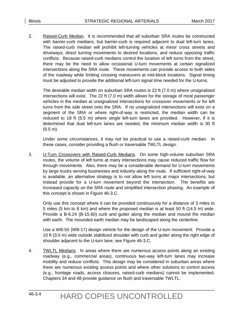
2. Raised-Curb Median. It is recommended that all suburban SRA routes be constructed with barrier-curb medians, but barrier-curb is required adjacent to dual left-turn lanes. The raised-curb median will prohibit left-turning vehicles at minor cross streets and driveways, direct turning movements to desired locations, and reduce opposing traffic conflicts. Because raised-curb medians control the location of left turns from the street, there may be the need to allow occasional U-turn movements at certain signalized intersections along the SRA route. These movements can provide access to both sides of the roadway while limiting crossing maneuvers at mid-block locations. Signal timing must be adjusted to provide the additional left-turn signal time needed for the U-turns.
The desirable median width on suburban SRA routes is 22 ft (7.0 m) where unsignalized intersections will exist. The 22 ft (7.0 m) width allows for the storage of most passenger vehicles in the median at unsignalized intersections for crossover movements or for left turns from the side street onto the SRA. If no unsignalized intersections will exist on a segment of the SRA or where right-of-way is restricted, the median width can be reduced to 18 ft (5.5 m) where single left-turn lanes are provided. However, if it is determined that dual left-turn lanes are needed, the minimum median width is 30 ft (9.5 m).
Under some circumstances, it may not be practical to use a raised-curb median. In these cases, consider providing a flush or traversable TWLTL design.
3. U-Turn Crossovers with Raised-Curb Medians. On some high-volume suburban SRA routes, the volume of left turns at many intersections may cause reduced traffic flow for through movements. Also, there may be a considerable demand for U-turn movements by large trucks serving businesses and industry along the route. If sufficient right-of-way is available, an alternative strategy is to not allow left turns at major intersections, but instead provide for a U-turn movement beyond the intersection. The benefits are increased capacity on the SRA route and simplified intersection phasing. An example of this concept is shown in Figure 46-3.C.
Only use this concept where it can be provided continuously for a distance of 3 miles to 5 miles (5 km to 8 km) and where the proposed median is at least 50 ft (14.5 m) wide. Provide a B-6.24 (B-15.60) curb and gutter along the median and mound the median with earth. The mounded earth median may be landscaped along the centerline.
Use a WB-55 (WB-17) design vehicle for the design of the U-turn movement. Provide a 10 ft (3.0 m) wide outside stabilized shoulder with curb and gutter along the right edge of shoulder adjacent to the U-turn lane; see Figure 46-3.C.
4. TWLTL Medians. In areas where there are numerous access points along an existing roadway (e.g., commercial areas), continuous two-way left-turn lanes may increase mobility and reduce conflicts. This design may be considered in suburban areas where there are numerous existing access points and where other solutions to control access (e.g., frontage roads, access closures, raised-curb medians) cannot be implemented. Chapters 34 and 48 provide guidance on flush and traversable TWLTL.

Illinois STRATEGIC REGIONAL ARTERIALS March 2017
46-3.5 HARD COPIES UNCONTROLLED
Notes: 1. Use the WB-55 (WB-17) design vehicle for the design of the U-turn movement. 2. The minimum distance is dependent on the design speed of the street, left-turning
volumes, and space needed for advance guide signs.
U-TURN CROSSOVERS WITH A RAISED-CURB MEDIAN
Figure 46-3.C

Illinois STRATEGIC REGIONAL ARTERIALS March 2017
46-3.6 HARD COPIES UNCONTROLLED
46-3.02(b) Additional Lanes
Some proposed suburban SRA routes may presently consist of a four- or five-lane pavement section through residential or commercial areas with minimal setbacks. It may not be feasible to obtain the additional right-of-way required for expansion into the recommended roadway cross section at these locations.
46-3.02(c) Vertical Clearances
The vertical clearances for suburban SRA routes are presented in Figure 46-3.E. Where practical on existing routes, vertical clearances may need to be increased to provide for the unrestricted movement of large vehicles. Bridges that do not provide a minimum of 14 ft 9 in (4.5 m) vertical clearance above the roadway are candidates for modification. Bridges which provide a vertical clearance of 14 ft 00 in (4.25 m) may remain in place, but should be considered for reconstruction or other means to achieve a minimum vertical clearance of 14 ft 9 in (4.5 m). Where the SRA route is an underpass, the recommended method to increase the vertical clearance is to lower the roadway through milling, raising the pier height, reconstructing the bridge or other methods. Carefully evaluate potential drainage and utility problems where these methods are proposed.
46-3.03 Access Management
The use of access management techniques is one of the most important concepts implemented on the SRA system. The number and configuration of access points to a suburban SRA route influence length of travel time and driver safety. Each driveway and cross street reduces mobility and safety. To improve access management, consider the following techniques:
1. Eliminate Local Street Access. To improve operations, consider closing some low-volume minor roads and local streets. The feasibility of terminating or rerouting the minor route will depend on local street traffic volumes, emergency vehicle response times, and the availability of alternative routes.
2. Restrict Curb Cuts. To improve mobility and safety on the suburban SRA route, consider the following restrictions:
a. Sideroad Access. Where a parcel of property has access available from a side street, only allow access from the non-SRA route.
b. Directional Movements. Where curb-cut access is allowed along a suburban SRA route, it is preferable that only right-in and right-out turns be permitted. This will prevent left-turn movements onto the SRA across through traffic lanes. An example of this design is shown in Figure 46-2.C.
c. Consolidating Access Points. In suburban areas where numerous curb-cut access points are present, it is recommended that the access be consolidated into single points at a desirable spacing of 500 ft (150 m) between access points.

Illinois STRATEGIC REGIONAL ARTERIALS March 2017
46-3.7 HARD COPIES UNCONTROLLED
This is illustrated in Figure 46-3.D. The properties should be interconnected through the use of cross-access easements.
d. Left-Turn Restrictions. Discourage left-turn movements from the SRA into curb-cut access points. However, where this prohibition may not be feasible, increase the length of the turn-lane storage to accommodate left-turn queues during peak hours.
3. Develop Internal Access. Where new development or redevelopment occurs adjacent to a suburban SRA, it is desirable to provide internal circulation roads within the development. Design the circulation roads to accommodate not only automobiles, but delivery trucks, transit, and bicycles. Also, provide sidewalks within the development. If a signal and median crossover are warranted at the new access point, the spacing should not be less than ¼ mile (400 m) to an adjacent signal.
Access management principles should be coordinated among communities along each suburban SRA route. Chapter 35 provides further guidance on access management techniques that are also applicable to suburban SRA routes.
CONSOLIDATED ACCESS (Suburban SRA)
Figure 46-3.D

Illinois STRATEGIC REGIONAL ARTERIALS March 2017
46-3.8 HARD COPIES UNCONTROLLED
46-3.04 Intersections
In addition to Chapter 36, the following is applicable to intersections on suburban SRA routes:
1. Turn Lanes. Section 36-3 provides the warrants and design criteria for turn lanes. Where developing turn lanes, it is important to maintain at least two through lanes in each direction. In addition, the following will apply:
a. Left-Turn Lanes. Provide left-turn lanes at all intersections. It is recommended that the turn lanes be offset to provide increased sight distance to opposing traffic. See Section 36-3.03 for the design of offset left-turn lanes.
b. Right-Turn Lanes. Provide right-turn lanes where warranted.
c. Dual Left-Turn Lanes. Where there are high left-turn volumes, consider providing dual left-turn lanes to alleviate congestion where the single left-turn lane storage length is inadequate (e.g., 350 ft (100 m)). Phasing for the dual left-turn lanes must operate under the “protected only” phasing. For access management, separate the dual left-turn lanes and the left turn taper from opposing through lanes by a raised-curb median; see Chapters 35 and 36. Within a suburban environment where development is eminent, provide a 30 ft (9.5 m) wide median to allow for future flexibility at major entrances with dual left-turn lanes.
2. Turning Radii. Insufficient turning radii for trucks can significantly affect capacity at an intersection. Small radii may require large trucks to slow down to maneuver through the turn, to encroach into opposing lanes, or encroach onto the curb. Design the curb radii to meet the expected design vehicle, typically a WB-50 (WB-15). Review turning radii improvements for their impacts on pedestrians and adjacent development. Design vehicles are discussed in Section 36-1.08.
3. Approaches. Intersections on suburban routes with more than four approaches can cause operational problems. To alleviate this problem, consider one of the following options:
• close one of the approaches,
• convert one of the approaches to one-way operation going away from the intersection,
• provide an extremely short signal timing on one of the approaches to reduce the desirability of the approach, or
• relocate the excess approaches away from the intersection; this is the most desirable option.
4. Channelization. In suburban locations, the recommended cross section consists of three through lanes in each direction, dual left-turn lanes, and exclusive right-turn lanes. To reduce the wide expanses of intersections, use center channelization and consider the

Illinois STRATEGIC REGIONAL ARTERIALS March 2017
46-3.9 HARD COPIES UNCONTROLLED
use of corner islands to direct the flow of vehicles through the intersection. Channelization also can be effective at intersections where approaches are not at or close to 90° angles. At these locations, channelization and corner islands can help guide motorists through the unusual turning movements that are often required. Chapter 36 provides guidance on the design of channelized intersections.
5. New Intersections. It is recommended that intersections with new local roads be restricted to right-in/right-out movements. A raised-curb median will restrict left-turn movements from the SRA to the local road, left-turn movements from the local road onto the SRA, and through movements on the local road across the SRA. However, alternative routes and emergency vehicular response times must be evaluated.
6. Intersection Lighting. All suburban SRA to SRA route intersections should have appropriate intersection lighting. See Chapter 56 for information on highway lighting.
7. Capacity. At intersections where capacity is limited and volumes are high, left-turn restrictions and the elimination of signalized turn phases may be necessary. This will increase the capacity on the SRA route and reduce intersection conflicts. Alternative routes or access will be required for the affected movements. In some instances, limiting left-turn movements to off-peak periods on the SRA route may be beneficial to through roadway operations.
46-3.05 Railroad Grade Separations
Providing a grade separation over an intersecting railroad can increase capacity and safety. However, the feasibility of this type improvement is dependent upon projected traffic volumes, roadway characteristics, posted speed, duration and volume of rail movements, and the amount of right-of-way available for overpass construction.
Evaluate all at-grade railroad intersections with suburban SRA routes for a potential grade separation. Preference for grade separation construction may be given to freight rail crossings where delays due to the length of freight trains are considerably longer than at crossings for passenger rail lines. However, the requirement for grade separations at commuter rail lines is important because peak rail and roadway traffic always coincide. Additional factors to assess include the proximity of the rail line to adjacent arterial intersections, access requirements, right-of-way availability, and projected traffic volumes on the suburban SRA.
At all locations where railroad grade separations are not feasible, investigate the use of constant warning time warning devices. Constant warning time (CWT) devices adjust the downtime of the gates based on the speed of the train. This helps reduce excessive delays to vehicular traffic caused by gates being down when trains are not present. This type of device can also recognize when a train is stopped. This can be beneficial where a train station is near an at-grade rail crossing. In some cases, it may be a more conservative design to have a simple DC circuit instead of the CWT circuitry. This proposal should be reviewed by someone who is knowledgeable in both crossing circuitry and train operations at the specific location.

Illinois STRATEGIC REGIONAL ARTERIALS March 2017
46-3.10 HARD COPIES UNCONTROLLED
46-3.06 Interchanges
Consider constructing an interchange if the projected level of service of an intersection in the design year is E or F using conventional improvements. Intersections that operate at level-of-service D or better generally are not candidates for interchange construction, unless unsafe geometric design features (e.g., excessive intersection skew) are present. Chapters 37 and 45 provide further guidance for interchange warrants and interchange design.
Suburban SRA routes are frequently characterized by a limited right-of-way availability. Interchange types that require the least amount of right-of-way (e.g., single point urban diamond, compressed diamond) are considered the most appropriate for suburban SRA routes. See Chapter 37 for further information.
For an intersection of two suburban SRA routes and where sufficient right-of-way is available, consider providing a cloverleaf interchange design. The advantage of this interchange type over the diamond interchange is that both intersecting facilities have uninterrupted through movements.
Under certain conditions, a U-turn movement could be added to a compressed diamond interchange between a suburban SRA route and a lower class/volume cross street. The underpass U-turn lane allows SRA vehicles to access an opposing frontage road without passing through signalized intersections on the cross streets. Figure 37-3.G illustrates this design.
All suburban SRA interchanges should have lighting. However, the lighting should not create “light pollution” problems from spillover into nearby residential areas.
46-3.07 Drainage
On suburban SRA routes, roadway drainage generally will consist of an enclosed system. During roadway reconstruction for lane additions or intersection widening, evaluate the existing drainage system for capacity or flooding problems. Any improvements to the existing drainage system must meet the criteria in the IDOT Drainage Manual.
46-3.08 Removal of On-Street Parking
On-street parking is currently permitted on some portions of SRA routes in suburban areas. On-street parking can significantly affect the capacity of the SRA route and may constitute a safety hazard as drivers enter and exit parking spaces. Where practical, consider permanently removing the on-street parking or restricting it during peak hours. Section 46-2.08 provides criteria for removal of on-street parking on urban SRA routes. This is also applicable to a suburban SRA route with one exception if the level-of-service on the suburban SRA route is C or worse, consider removing the on-street parking.
Illinois STRATEGIC REGIONAL ARTERIALS March 2017
46-3.11 HARD COPIES UNCONTROLLED
46-3.09 Traffic Control Devices
46-3.09(a) Traffic Signals
Section 46-2.09 provides information on traffic signals for urban areas. In addition, the following applies to traffic signals in suburban areas:
1. Signal Type. Provide fully actuated traffic signals at all signalized intersections.
2. Signal Interconnection. Where feasible, interconnect all signalized intersections with a spacing of ½ mile (800 m) or less into signal systems. The interconnection is used to provide signal coordination and vehicular progression along the SRA route. Synchronize all signal systems along suburban SRA’s for vehicular progression based on a traffic engineering study.
3. Spacing. If a signal is warranted at a local road or street, the spacing should not be less than ¼ mile (400 m) to an adjacent signal, but ½ mile (800 m) spacing is preferred.
4. Bus Preemption. All signalized intersections on suburban SRA routes should be capable of priority preemption for express bus service. This preemption capability should only be used to keep buses on schedule. Coordinate the preemption by buses with vehicular progression along the SRA route.
5. Level of Service. The goal of the traffic signal timing along suburban SRA routes is to achieve a level-of-service C or better for the arterial through lanes. To achieve this, it may be necessary to lower the level-of-service for the turning movements and cross streets to maximize the through movements on the SRA.
46-3.09(b) Warrants for Traffic Signals
Install traffic signals on SRA routes where the signal warrants in the Illinois MUTCD are met.
46-3.09(c) Overhead Signing
All suburban SRA-to-SRA route intersections should have advance overhead signing with route numbers and/or street names and, where appropriate, regional destinations. The lettering should be large enough to read at a distance of 350 ft to 400 ft (100 m to 125 m).
46-3.09(d) Stop Sign Removal
Stop sign control for traffic movements on an SRA route is inconsistent with giving priority to the SRA through movement. Therefore, remove stop signs from the through lanes of a suburban SRA route. However, it will be necessary to conduct a traffic engineering study to determine the appropriate traffic control at the location for both the SRA route and the intersecting cross street.

Illinois STRATEGIC REGIONAL ARTERIALS March 2017
46-3.12 HARD COPIES UNCONTROLLED
46-3.09(e) Pavement Markings
Because of their durability and visibility, only use high-type pavement markings on suburban SRA routes. High-type pavement markings include thermoplastic, epoxy, and pre-formed plastics. Also, include raised pavement markers on suburban SRA routes. Space raised pavement markers according to the criteria in the Bureau of Operations Policies and Procedures Manual and the Highway Standards. In addition, place reflectors on top of the raised-curb median.
46-3.09(f) Driver Information Systems
In addition to providing signs and pavement markings to guide motorists, it may be necessary to furnish information on congestion, construction, or other incidents which may affect their trip. Driver information systems may include variable or fixed message signing, radio and television traffic reports, newspaper articles, and brochures.
46-3.10 Trucks
Locate all loading and unloading areas off the suburban SRA street.
46-3.11 Transit
46-3.11(a) Improvements
Techniques associated with mass transit that may be applicable in certain suburban situations are described in Section 46-2.11. For suburban areas, it will also be necessary to improve transit station accessibility using one or more of the following techniques:
1. Actuated Traffic Signals. Transit station usage is extremely intensive during peak periods. Incorporating traffic signals on the SRA or connecting streets with phasing and timings that are responsive to the varying levels of traffic during the day will make transit stations more accessible and reduce delays. If new traffic signals are proposed at transit stations, they should meet the established traffic volume warrants and criteria for spacing of signals.
2. Turn Lanes. To maximize through traffic movements for vehicles not wishing to access transit stations, provide channelized right- and left-turn lanes for vehicles turning into transit stations. If demand is sufficient, provide dual left- and/or right-turn lanes. Appropriate storage bay lengths for turning vehicles must also be implemented.
3. Park and Ride Lots. Investigate providing parking for commuters. If a potential parking lot site is judged too far from the transit station, then parking in this area could be free or at a greatly reduced rate to encourage use. Another option is to provide satellite lots with free shuttle buses to the stations. Preferential parking stalls nearest to transit stations could be designated for High Occupancy Vehicles. Also, provide secure bicycle

Illinois STRATEGIC REGIONAL ARTERIALS March 2017
46-3.13 HARD COPIES UNCONTROLLED
parking at transit stations. Include left- and right-turn lanes at the entrance to the facility to enhance safety.
4. Transit Access. If substantial parking for a transit station is located on the opposite side of a SRA route, consider providing appropriate access for pedestrians.
46-3.11(b) Express Bus Service
Bus service on suburban SRA routes should be limited to express buses that are equipped with priority signal preemption capability that can be deployed when they are running behind schedule. However, coordinate the bus preemption with existing vehicular progression along the SRA route.
Design stops as bus turnouts; see Chapter 58. Walkways to stops of intersecting services will facilitate transfers and promote safety. Nearside and far-side bus stop configurations should be planned to minimize distances between connecting lines.
46-3.12 HOV Lanes
High occupancy vehicle (HOV) lanes designated for buses, carpools, and vans may be appropriate in selected areas with high levels of transit ridership and ridesharing activity. Note that there should also be adequate capacity to accommodate traffic in the general use lanes.
46-3.13 Pedestrians and Bicyclists
On suburban SRA routes, more options are available for accommodating pedestrian and bicycle access than in urban areas. For example, although right-of-way availability is still a critical issue, dense development immediately adjacent to the roadway is not as common an occurrence as in urban areas. Provisions for bicyclists and pedestrians may be accommodated within the SRA right-of-way itself. In suburban situations, alternative parallel routes may not always be available.
Access across major obstacles (e.g., river crossings, railroads, limited access facilities) or barriers will be accommodated by the SRA if alternative access is not feasible. The choice of how to provide access within the SRA corridor is determined on a case-by-case basis. Under all situations, the goal is to provide a continuous system of bicycle and pedestrian routes. Chapter 17 provides guidance on the design of bicycle and pedestrian facilities. Chapter 58 provides information on accessibility requirements.
46-3.14 Environmental Considerations
The environmental analysis component of the SRA planning process is primarily an inventory of existing conditions. The inventory identifies those environmental resources in the corridor and probable impacts based on roadway improvements. Environmental assessments will be

Illinois STRATEGIC REGIONAL ARTERIALS March 2017
46-3.14 HARD COPIES UNCONTROLLED
performed during Phase I design work. These are discussed in Part III “Environmental Procedures” of this Manual.
46-3.15 Right-of-Way Acquisition and Corridor Protection
A major goal of the SRA planning process is to identify and protect future right-of-ways that are needed to construct the recommended roadway design configuration. Suburban right-of-ways may adjoin both developed and undeveloped properties. During Phase I studies, local governments should be contacted and encouraged to work with roadway jurisdictional agencies. This will ensure that adequate right-of-way is provided for suburban SRA routes in the approval process for new developments. Local governments should review their building setback requirements to ensure that all new building construction is outside the recommended SRA right-of-way widths. This will protect the right-of-way for future roadway expansion.
See the Bureau of Land Acquisition’s Manual of Policies and Procedures for information on corridor protection procedures.
46-3.16 Tables of Design Criteria
Figure 46-3.E presents the Department’s design criteria for new construction and reconstruction of suburban strategic regional arterial projects. Figure 46-3.F provides the alignment criteria for suburban SRA routes. The designer should realize that some of the cross section elements included in the figure (e.g., TWLTL widths) are not automatically warranted in the project design. The values in the figure only apply after the decision has been made to include the element in the highway cross section.

Illinois STRATEGIC REGIONAL ARTERIALS March 2017
46-3.15 HARD COPIES UNCONTROLLED
GEO
MET
RIC
DES
IGN
CR
ITER
IA F
OR
SU
BU
RBA
N S
TRA
TEG
IC R
EGIO
NA
L A
RTE
RIA
LS (S
RA
) (N
ew C
onst
ruct
ion/
Rec
onst
ruct
ion)
(U
S C
usto
mar
y)
Figu
re 4
6-3.
E (1
of 2
)

Illinois STRATEGIC REGIONAL ARTERIALS March 2017
46-3.16 HARD COPIES UNCONTROLLED
GEO
MET
RIC
DES
IGN
CR
ITER
IA F
OR
SU
BU
RBA
N S
TRA
TEG
IC R
EGIO
NA
L A
RTE
RIA
LS (S
RA
) (N
ew C
onst
ruct
ion/
Rec
onst
ruct
ion)
(M
etric
)
Figu
re 4
6-3.
E (1
of 2
)
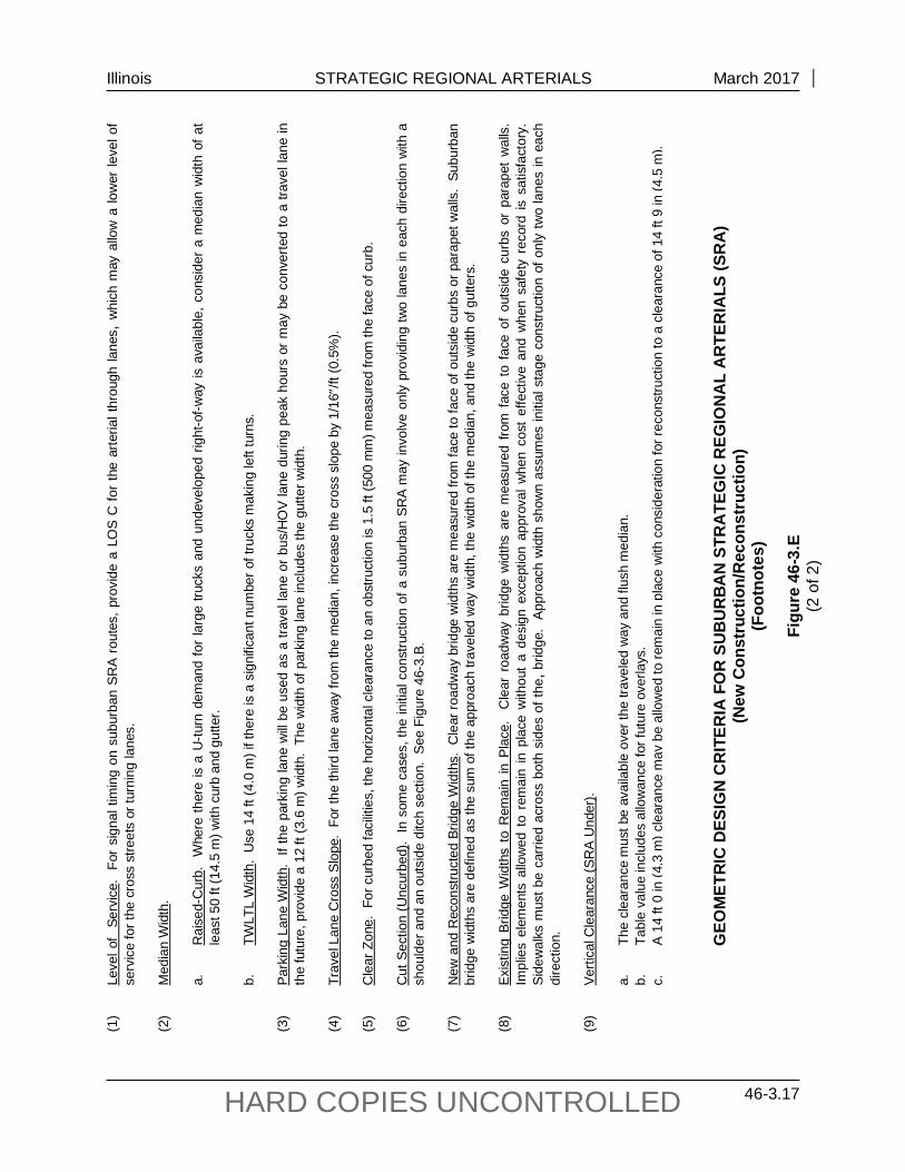
Illinois STRATEGIC REGIONAL ARTERIALS March 2017
46-3.17 HARD COPIES UNCONTROLLED
(1)
Leve
l of
Serv
ice.
Fo
r si
gnal
tim
ing
on s
ubur
ban
SRA
rout
es, p
rovi
de a
LO
S C
for
the
arte
rial t
hrou
gh la
nes,
whi
ch m
ay a
llow
a lo
wer
leve
l of
serv
ice
for t
he c
ross
stre
ets
or tu
rnin
g la
nes.
(2
) M
edia
n W
idth
.
a.
Rai
sed-
Cur
b.
Whe
re th
ere
is a
U-tu
rn d
eman
d fo
r la
rge
truck
s an
d un
deve
lope
d rig
ht-o
f-way
is a
vaila
ble,
con
side
r a
med
ian
wid
th o
f at
leas
t 50
ft (1
4.5
m) w
ith c
urb
and
gutte
r.
b.
TWLT
L W
idth
. U
se 1
4 ft
(4.0
m) i
f the
re is
a s
igni
fican
t num
ber o
f tru
cks
mak
ing
left
turn
s.
(3)
Park
ing
Lane
Wid
th.
If th
e pa
rkin
g la
ne w
ill be
use
d as
a tr
avel
lane
or b
us/H
OV
lane
dur
ing
peak
hou
rs o
r may
be
conv
erte
d to
a tr
avel
lane
in
the
futu
re, p
rovi
de a
12
ft (3
.6 m
) wid
th.
The
wid
th o
f par
king
lane
incl
udes
the
gutte
r wid
th.
(4)
Trav
el L
ane
Cro
ss S
lope
. Fo
r the
third
lane
aw
ay fr
om th
e m
edia
n, in
crea
se th
e cr
oss
slop
e by
1/1
6″/ft
(0.5
%).
(5)
Cle
ar Z
one.
For
cur
bed
faci
litie
s, th
e ho
rizon
tal c
lear
ance
to a
n ob
stru
ctio
n is
1.5
ft (5
00 m
m) m
easu
red
from
the
face
of c
urb.
(6
) C
ut S
ectio
n (U
ncur
bed)
. In
som
e ca
ses,
the
initi
al c
onst
ruct
ion
of a
sub
urba
n SR
A m
ay in
volv
e on
ly p
rovi
ding
two
lane
s in
eac
h di
rect
ion
with
a
shou
lder
and
an
outs
ide
ditc
h se
ctio
n. S
ee F
igur
e 46
-3.B
. (7
) N
ew a
nd R
econ
stru
cted
Brid
ge W
idth
s. C
lear
road
way
brid
ge w
idth
s ar
e m
easu
red
from
face
to fa
ce o
f out
side
cur
bs o
r par
apet
wal
ls.
Subu
rban
br
idge
wid
ths
are
defin
ed a
s th
e su
m o
f the
app
roac
h tra
vele
d w
ay w
idth
, the
wid
th o
f the
med
ian,
and
the
wid
th o
f gut
ters
. (8
) Ex
istin
g Br
idge
Wid
ths
to R
emai
n in
Pla
ce.
Cle
ar r
oadw
ay b
ridge
wid
ths
are
mea
sure
d fro
m f
ace
to f
ace
of o
utsi
de c
urbs
or
para
pet
wal
ls.
Impl
ies
elem
ents
allo
wed
to
rem
ain
in p
lace
with
out
a de
sign
exc
eptio
n ap
prov
al w
hen
cost
effe
ctiv
e an
d w
hen
safe
ty r
ecor
d is
sat
isfa
ctor
y.
Side
wal
ks m
ust b
e ca
rrie
d ac
ross
bot
h si
des
of th
e, b
ridge
. Ap
proa
ch w
idth
sho
wn
assu
mes
initi
al s
tage
con
stru
ctio
n of
onl
y tw
o la
nes
in e
ach
dire
ctio
n.
(9)
Verti
cal C
lear
ance
(SR
A U
nder
).
a.
The
clea
ranc
e m
ust b
e av
aila
ble
over
the
trave
led
way
and
flus
h m
edia
n.
b.
Ta
ble
valu
e in
clud
es a
llow
ance
for f
utur
e ov
erla
ys.
c.
A
14 ft
0 in
(4.3
m) c
lear
ance
may
be
allo
wed
to re
mai
n in
pla
ce w
ith c
onsi
dera
tion
for r
econ
stru
ctio
n to
a c
lear
ance
of 1
4 ft
9 in
(4.5
m).
GEO
MET
RIC
DES
IGN
CR
ITER
IA F
OR
SU
BU
RBA
N S
TRA
TEG
IC R
EGIO
NA
L A
RTE
RIA
LS (S
RA
) (N
ew C
onst
ruct
ion/
Rec
onst
ruct
ion)
(F
ootn
otes
)
Figu
re 4
6-3.
E (2
of 2
)

Illinois STRATEGIC REGIONAL ARTERIALS March 2017
46-3.18 HARD COPIES UNCONTROLLED
ALI
GN
MEN
T C
RIT
ERIA
FO
R S
UB
UR
BA
N S
TRAT
EGIC
REG
ION
AL
AR
TER
IALS
(SR
A)
(US
Cus
tom
ary)
Figu
re 4
6-3.
F

Illinois STRATEGIC REGIONAL ARTERIALS March 2017
46-3.19 HARD COPIES UNCONTROLLED
ALI
GN
MEN
T C
RIT
ERIA
FO
R S
UB
UR
BA
N S
TRAT
EGIC
REG
ION
AL
AR
TER
IALS
(SR
A)
(Met
ric)
Figu
re 4
6-3.
F

Illinois STRATEGIC REGIONAL ARTERIALS March 2017
46-3.20 HARD COPIES UNCONTROLLED

Illinois STRATEGIC REGIONAL ARTERIALS November 2014
46-4.1 HARD COPIES UNCONTROLLED
46-4 RURAL SRA ROUTES
46-4.01 General Roadway Features
46-4.01(a) General
The recommended design for rural SRA’s is to construct two or three lanes in each direction separated by a wide depressed median. The wide median will allow the addition of future through lanes in the median with minimum disruption to highway users and surrounding development. The facility may include two-way frontage roads on both sides of the mainline highway. Sufficient right-of-way should be reserved initially to allow for the recommended design. Figure 46-4.A illustrates a plan view design configuration for a rural SRA with frontage roads. Figure 46-4.B illustrates the recommended cross section for a rural four-lane SRA. Initial stage construction and bypass routes around communities would not involve the use of frontage roads. For an illustration of a superelevated section, see Figure 45-2.E.
46-4.01(b) Bypass Facilities
Many rural SRA routes are characterized by relatively lengthy segments of roadway that connect existing communities. A rural SRA route that approaches a community may better serve the concept of regional mobility if it bypasses the town. There are two options to consider for rural SRA routes at a community. One is to designate an existing highway through the town as the planned SRA route, and the other is to construct a new bypass facility. Only consider the construction of a bypass facility where there are large tracts of undeveloped land or unused rights-of-way. Also, every effort should be made to use the rights-of-way of existing roadways for the bypass alignment. As a minimum, any bypass facility should be designed with partial access control; see Chapter 45. Where full access control can be obtained, the bypass should be designed accordingly; see Chapter 44.
46-4.02 Geometric Design Elements
46-4.02(a) Median Types
When providing medians on rural SRA routes, consider the following:
1. Type. Typically, use a depressed median on rural SRA routes. This median type will provide space for left-turning vehicles at crossroads, direct turning movements to desired locations, reduce opposing traffic conflicts, and allow for high operating speeds.
2. Width. For rural SRA routes, the minimum width is 50 ft (15 m). Where there is a high probability of need for three lanes in each direction in the future, use a 74 ft (22.2 m) wide median initially. However, where right-of-way is restricted, a 50 ft (15 m) wide median may be used initially where six lanes will be required in the future. The median can be converted to a 26 ft (7.8 m) wide median with a concrete median barrier.

Illinois STRATEGIC REGIONAL ARTERIALS November 2014
46-4.2 HARD COPIES UNCONTROLLED
TYPI
CA
L R
UR
AL
SRA
RO
UTE
WIT
H F
RO
NTA
GE
RO
AD
S (1
mile
(1.6
km
) Seg
men
t)
Figu
re 4
6-4.
A
Bef
ore
front
age
road
s ar
e co
nstru
cted
, the
mid
-poi
nt m
inor
arte
rial m
ay b
e co
nnec
ted
dire
ctly
to th
e m
ainl
ine
and
prov
ided
with
righ
t-in
and
right
-out
turn
s.
Not
e:
See
Sec
tion
36-1
.08
for s
elec
tion
of a
ppro
pria
te d
esig
n ve
hicl
e.

Illinois STRATEGIC REGIONAL ARTERIALS November 2014
46-4.3 HARD COPIES UNCONTROLLED
RU
RA
L SR
A C
RO
SS S
ECTI
ON
(Typ
ical
Des
ign
with
Fro
ntag
e R
oads
)
Figu
re 4
6-4.
B
Not
e:
Initi
al c
onst
ruct
ion
usua
lly w
ill no
t inc
lude
fron
tage
road
s.

Illinois STRATEGIC REGIONAL ARTERIALS November 2014
46-4.4 HARD COPIES UNCONTROLLED
3. Median Crossovers. Only permit median crossovers at major intersections. Space these crossovers at intervals of 1 mile (1.5 km) or greater. Where local access to a crossroad is severely restricted or will cause significant delay for a large number of turning vehicles, crossovers may be reduced to ½ mile (800 m) intervals. However, do not use this spacing extensively along rural SRA routes. The intent of rural SRA routes is to give priority to through movements and provide for high operating speeds.
4. Flush Median with Concrete Median Barrier (CMB). This median type may be used where right-of-way is restricted; see Figure 36-3.M and Section 34-3.03.
46-4.02(b) Additional Lanes
On rural SRA routes, the desirable design is to provide sufficient right-of-way to allow two lanes in each direction with a depressed median and two-way frontage roads on each side. Where future capacity is required, a third lane can be constructed in the median.
The usual design to complete the multilane cross section is to provide a depressed median adjacent to an existing roadway and to construct a new roadway parallel to the existing lanes; see Figure 46-4.B. In some cases, it may be more appropriate to center all new construction about the centerline of the existing pavement. However, this would require all new pavements and a close examination of construction phasing for the maintenance of traffic flow.
46-4.02(c) Vertical Clearances
The vertical clearances for rural SRA routes are presented in Figure 46-4.C. Where practical on existing routes, vertical clearances may need to be increased to provide for the unrestricted movement of large vehicles. Existing bridges that do not provide a minimum of 16 ft 6 in (5.0 m) vertical clearance above the roadway are candidates for modification. Bridges which provide a vertical clearance of 16 ft 00 in (4.9 m) may remain in place, but should be considered for reconstruction or other means to achieve a minimum vertical clearance of 16 ft 6 in (5.0 m). Where the SRA route is an underpass, the recommended method to increase the vertical clearance is to lower the roadway through milling, raising the pier height, reconstructing the bridge, or other methods. Carefully evaluate potential drainage and utility problems.
46-4.03 Access Management
Sections 46-2.03 and 46-3.03 provide guidance on access management techniques that are also applicable to rural SRA routes. In addition, consider the following:
1. Frontage Roads. Because of the potential hazards introduced by intermittent access points, the most desirable form of access management is to provide two-way frontage roads along the SRA route. If the frontage roads are not constructed initially, consider providing sufficient right-of-way for incorporation of future frontage roads.

Illinois STRATEGIC REGIONAL ARTERIALS November 2014
46-4.5 HARD COPIES UNCONTROLLED
Where the frontage road is flared out at an intersection, do not allow development to occur within the interior area of the “jughandle.” This area may be an appropriate location for park-and-ride lots; see Figure 46-4.A. Protection of this area will also allow the construction of a diamond interchange in the future.
2. Minor Road Access. The high speeds on rural SRA routes can make intersections with minor side roads potentially hazardous. Signalization is not recommended due to the delays that would be created on the rural SRA route. Desirably, terminate access to the minor road at the frontage road. If this is not practical, the next option is only to allow right-in and right-out maneuvers on the SRA route.
46-4.04 Intersections
In addition to Chapter 36, the following is applicable to intersections on rural SRA routes:
1. Turn Lanes. Section 36-3 provides the warrants and design criteria for turn lanes. In addition, the following will apply:
a. Left-Turn Lanes. Provide tapered offset left-turn lanes at all signalized and major intersections. Use a parallel, left-turn lane design at minor road intersections where an intermediate median crossover is proposed.
b. Right-Turn Lanes. In general, provide right-turn lanes at all intersections.
c. U-Turn Crossovers. Where a crossover is required for U-turns, provide a parallel left-turn lane design into the crossover. The left-turn lane may be designed for 50 mph (80 km/hr) design speed.
2. Turning Radii. Insufficient turning radii for trucks can significantly affect the capacity of an intersection. Design the right- and left-turning radii to meet the expected design vehicle. Intersection design vehicles and truck routes are discussed in Section 36-1.08.
3. Channelization. To reduce the wide expanses of intersections, use corner islands to direct the flow of right-turning vehicles through the intersection. Channelization also can be effective at intersections where approaches are not at or close to 90° angles. At these locations, channelization and corner islands can help guide motorists through unusual turning movements. Section 36-3 illustrates typical design features that should be used at rural SRA intersections.
4. New Intersections. Where new local roads are proposed, restrict them to right-in/right-out movements. The depressed median will restrict left-turn movements from the SRA to the local road, left-turn movements from the local road to the SRA, and through movements on the local road across the SRA. However, alternative routes and emergency vehicular response times must also be evaluated and may result in the design of a median crossover. When frontage roads are provided, remove these minor roads from the SRA route and tee them into the frontage road; see Figure 46-4.A.

Illinois STRATEGIC REGIONAL ARTERIALS November 2014
46-4.6 HARD COPIES UNCONTROLLED
5. Intersection Lighting. All major intersections should have appropriate intersection lighting. See Chapter 56 for information on highway lighting.
46-4.05 Railroad Grade Separations
Where there is one or more trains per day crossing a rural SRA, consider providing for a future structure over the railroad. The feasibility of this type of improvement is dependent upon projected traffic volumes, roadway characteristics, posted speed, duration and volume of rail movements, and the amount of right-of-way available for overpass construction. Right-of-way should be protected at all rural SRA routes that will cross railroads at-grade.
In general, do not provide a grade-separation structure for frontage roads adjacent to the rural SRA route. Instead, flare the frontage roads out an appropriate distance from SRA grade-separation structure so that sight lines along the tracks are not blocked by the embankment and structure.
46-4.06 Interchanges
Right-of-way should be protected at all major intersections with rural SRA routes for eventual interchange construction. This will help to eliminate most signalized intersections and improve safety and mobility. Right-of-way is typically available at rural SRA crossroads to construct a diamond interchange; see Chapter 37. Where right-of-way is restricted, consider using a single point urban diamond or compressed diamond interchange. Figure 46-4.A shows the typical design of how frontage roads are flared out at major intersections initially, and how they might be incorporated into an interchange design.
If two intersecting rural SRA routes have unusually high projected traffic volumes and where sufficient right-of-way is available, consider providing a cloverleaf interchange design. The projected level of service on both routes should be level D or lower with conventional improvements before this option is considered. The route with the highest projected volumes should be considered to have the priority movement. The crossover of the lower priority route should have a design speed of 60 mph (100 km/hr) through the interchange.
All rural SRA interchanges should have lighting. However, lighting should not create “light pollution” problems from spillover into nearby residential areas.
46-4.07 Drainage
On rural SRA routes, open ditches will be used to accommodate roadway drainage. Design of ditches and drainage appurtenances must meet the criteria in the IDOT Drainage Manual. Outside ditches should be at least 6 ft (1.8 m) wide to provide for extra detention storage and adequate clear zone.

Illinois STRATEGIC REGIONAL ARTERIALS November 2014
46-4.7 HARD COPIES UNCONTROLLED
46-4.08 Frontage Roads
Frontage roads may be appropriate along rural SRA routes to separate slower local traffic from the higher speed through traffic on the SRA route and to reduce the number of conflict points. The most desirable option is to provide two-way frontage roads on both sides of the rural SRA route. Direct access to the SRA route should only occur at major crossroad intersections. Design criteria for frontage roads are presented in Chapter 44. Between major intersections, the total SRA right-of-way should be approximately 300 ft to 350 ft (90 m to 100 m). At intersections, flare the frontage road out approximately 400 ft (125 m) to create separate intersections on the crossroad between the frontage road and the rural SRA; see Figure 46-4.A. This spacing will also allow for signal coordination.
46-4.09 Traffic Control Devices
46-4.09(a) Traffic Signals
Provide fully actuated traffic signals at all signalized intersections on rural SRA routes. Chapter 57 and the Bureau of Operations Policies and Procedures Manual provide additional information on traffic signals.
46-4.09(b) Overhead Signing
All rural SRA-to-SRA route intersections should have advance overhead signing with route numbers and/or road names and, where appropriate, regional destinations. The lettering should be large enough to read at a distance of 400 ft to 500 ft (125 m to 150 m).
46-4.09(c) Stop Sign Removal
Stop sign control for traffic movements on an SRA route is inconsistent with giving priority to the SRA through movement. Therefore, remove all stop signs from the through lanes of a rural SRA route. However, it will be necessary to conduct a traffic engineering study to determine the appropriate traffic control at the location for both the SRA route and the intersecting crossroad.
46-4.09(d) Pavement Markings
Because of their durability and visibility, only use high-type pavement markings on rural SRA routes. High-type pavement markings include thermoplastic, epoxy, and pre-formed plastics. Include raised pavement markers and delineators on rural SRA routes. Raised pavement markers introduce an element of safety to the SRA route during inclement weather. Space raised pavement markers and delineators according to the Bureau of Operations Policies and Procedures Manual and the IDOT Highway Standards.
Illinois STRATEGIC REGIONAL ARTERIALS November 2014
46-4.8 HARD COPIES UNCONTROLLED
46-4.10 Transit
46-4.10(a) Improvements
Techniques associated with mass transit that may be applicable in certain rural situations are described in Section 46-2.11. For rural areas, it will also be necessary to improve transit station accessibility as discussed in Section 46-3.11. Ridesharing is a common approach to transit in rural areas. The “jughandle” design of the frontage road at major crossroad intersections typically provides adequate locations for park-and-ride facilities; see Figure 46-4.A.
46-4.10(b) Express Bus Service
Bus service on rural SRA routes should be limited to express buses that are equipped with priority signal preemption capability that can be deployed when they are running behind schedule. However, coordinate the bus preemption with existing vehicular progression along the SRA route. Bus stop locations generally should be located off the rural SRA route on side roads or park-and-ride lots. Space these stops at approximately 5 mile (8 km) intervals. Where it is impractical to locate bus stops off the SRA route, design bus turnouts and stops according to the criteria in Chapter 58.
46-4.11 Pedestrians and Bicyclists
The criterion for pedestrians and bicyclists presented in Section 46-3.13 is also applicable for rural SRA routes.
46-4.12 Environmental Considerations
The environmental analysis component of the SRA planning process is primarily an inventory of existing conditions. The inventory identifies those environmental resources in the corridor and probable impacts based on roadway improvements. Environmental assessments will be performed during the Phase I design work. These are discussed in Part III “Environmental Procedures” of this Manual.
46-4.13 Right-of-Way
Section 46-3.15 provides guidance for protecting future right-of-way needs which is also applicable to rural SRA routes. Also the Illinois Highway Code, 605 ILCS 5/4-510 provides guidance on the use of protective right-of-way buying as it applies to existing alignments.
46-4.14 Tables of Design Criteria
Figure 46-4.C presents the Department’s design criteria for new construction and reconstruction of rural strategic regional arterial projects. Figure 46-4.D presents the alignment of criteria for

Illinois STRATEGIC REGIONAL ARTERIALS November 2014
46-4.9 HARD COPIES UNCONTROLLED
rural SRA routes. The designer should realize that some of the cross section elements included in the figure (e.g., flush median with concrete barrier) are not automatically warranted in the project design. The values in the figure only apply after the decision has been made to include the element in the highway cross section.

Illinois STRATEGIC REGIONAL ARTERIALS November 2014
46-4.10 HARD COPIES UNCONTROLLED
GEO
MET
RIC
DES
IGN
CR
ITER
IA F
OR
RU
RA
L ST
RA
TEG
IC R
EGIO
NA
L A
RTE
RIA
LS (S
RA
) (N
ew C
onst
ruct
ion/
Rec
onst
ruct
ion)
(U
S C
usto
mar
y)
Figu
re 4
6-4.
C (1
of 2
)

Illinois STRATEGIC REGIONAL ARTERIALS November 2014
46-4.11 HARD COPIES UNCONTROLLED
GEO
MET
RIC
DES
IGN
CR
ITER
IA F
OR
RU
RA
L ST
RA
TEG
IC R
EGIO
NA
L A
RTE
RIA
LS (S
RA
) (N
ew C
onst
ruct
ion/
Rec
onst
ruct
ion)
(M
etric
)
Figu
re 4
6-4.
C (1
of 2
)

Illinois STRATEGIC REGIONAL ARTERIALS November 2014
46-4.12 HARD COPIES UNCONTROLLED
(1)
Acce
ss M
anag
emen
t. D
irect
acc
ess
to th
e SR
A ro
ute
will
be c
ontro
lled
by fu
ture
two-
way
fron
tage
road
s. W
here
byp
ass
rout
es a
re p
ropo
sed
arou
nd c
omm
uniti
es, t
he b
ypas
s de
sira
bly
shou
ld b
e fu
lly a
cces
s co
ntro
lled
or, a
t a m
inim
um, p
artia
lly a
cces
s co
ntro
lled.
(2
) Tr
avel
ed W
ay W
idth
. Ex
istin
g 22
ft (6
.6 m
) wid
th m
ay re
mai
n in
pla
ce.
(3
) Le
ft Sh
ould
er W
idth
. C
onsi
der p
rovi
ding
a 8
ft (2
.4 m
) sho
ulde
r wid
th a
nd 1
V:5H
med
ian
slop
es w
here
leve
l of s
ervi
ce is
app
roac
hing
“C.”
(4)
Flus
h M
edia
n W
idth
. O
nly
use
flush
med
ians
with
CM
B w
here
rig
ht-o
f-way
or
topo
grap
hy re
stric
ts th
e us
e of
a d
epre
ssed
med
ian.
C
onsi
der
prov
idin
g w
ider
med
ians
whe
re re
quire
d fo
r sno
w s
tora
ge.
(5)
Trav
el L
ane
Cro
ss S
lope
. Fo
r the
add
ition
al la
ne a
way
from
the
crow
n la
nes,
incr
ease
the
cros
s sl
ope
by 1
/16″
/ft (0
.5%
). (6
) C
lear
Zon
e.
The
clea
r zo
ne w
ill va
ry a
ccor
ding
to d
esig
n sp
eed,
traf
fic v
olum
es, s
ide
slop
es, a
nd h
oriz
onta
l cur
vatu
re.
For r
estri
cted
rig
ht-o
f-w
ay c
ondi
tions
, see
Fig
ure
34-4
.D.
(7)
Ditc
h Bo
ttom
Wid
th.
Prov
ide
a w
ider
out
side
ditc
h bo
ttom
whe
re d
eten
tion
stor
age
of s
torm
wat
er is
a c
onsi
dera
tion.
(8
) Ba
ck S
lope
. W
here
the
heig
ht o
f cut
exc
eeds
10
ft (3
m),
cons
ider
usi
ng a
1V:
2H b
ack
slop
e be
yond
the
clea
r zon
e. A
lso,
for h
eigh
ts g
reat
er
than
30
ft (9
m),
cons
ider
the
use
of b
ench
ing.
(9
) Fi
ll Sl
ope.
Fo
r fill
heig
hts
grea
ter
than
30
ft (9
m),
use
a 1V
:2H
uni
form
slo
pe w
ith a
road
side
bar
rier a
long
the
shou
lder
. Al
so, f
or fi
ll he
ight
s gr
eate
r tha
n 30
ft (9
m),
cons
ider
the
use
of b
ench
ing.
(1
0)
New
and
Rec
onst
ruct
ed B
ridge
Wid
ths.
C
lear
roa
dway
brid
ge w
idth
s ar
e m
easu
red
from
face
to fa
ce o
f par
apet
s or
rails
. Br
idge
wid
ths
are
norm
ally
def
ined
as
the
sum
of t
he a
ppro
ach
trave
led
way
wid
th a
nd th
e w
idth
of t
he p
aved
sho
ulde
rs.
(11)
Ex
istin
g Br
idge
Wid
ths
to R
emai
n in
Pla
ce.
Cle
ar ro
adw
ay b
ridge
wid
ths
are
mea
sure
d fro
m fa
ce to
face
of p
arap
ets
or ra
ils.
Impl
ies
elem
ents
al
low
ed to
rem
ain
in p
lace
with
out a
des
ign
exce
ptio
n ap
prov
al w
hen
cost
effe
ctiv
e an
d w
hen
safe
ty re
cord
is s
atis
fact
ory.
(1
2)
Verti
cal C
lear
ance
(SR
A U
nder
).
a.
The
clea
ranc
e m
ust b
e av
aila
ble
over
the
trave
led
way
and
any
pav
ed s
houl
ders
.
b.
Tabl
e va
lue
incl
udes
allo
wan
ce fo
r fut
ure
over
lays
.
GEO
MET
RIC
DES
IGN
CR
ITER
IA F
OR
RU
RA
L ST
RA
TEG
IC R
EGIO
NA
L A
RTE
RIA
LS (S
RA
) (N
ew C
onst
ruct
ion/
Rec
onst
ruct
ion)
Foot
note
s to
Fig
ure
46-4
.C
(2 o
f 2)

Illinois STRATEGIC REGIONAL ARTERIALS November 2014
46-4.13 HARD COPIES UNCONTROLLED
ALI
GN
MEN
T C
RIT
ERIA
FO
R R
UR
AL
STR
ATE
GIC
REG
ION
AL
AR
TER
IALS
(SR
A)
(US
Cus
tom
ary)
Figu
re 4
6-4.
D

Illinois STRATEGIC REGIONAL ARTERIALS November 2014
46-4.14 HARD COPIES UNCONTROLLED
ALI
GN
MEN
T C
RIT
ERIA
FO
R R
UR
AL
STR
ATE
GIC
REG
ION
AL
AR
TER
IALS
(SR
A)
(Met
ric)
Figu
re 4
6-4.
D

Illinois STRATEGIC REGIONAL ARTERIALS September 2012
46-5.1 HARD COPIES UNCONTROLLED
46-5 REFERENCES
1. A Policy on Geometric Design of Highways and Streets, AASHTO, 2011.
2. Strategic Regional Arterial: Design Concept Report, IDOT, February 1994.
3. SRA Access Management Policy, District 1 Bureau of Traffic, IDOT, 1998.
4. Guide for the Design of High Occupancy Vehicle Facilities, AASHTO, 2004.

Illinois STRATEGIC REGIONAL ARTERIALS September 2012
46-5.2 HARD COPIES UNCONTROLLED