STRANTROL SYSTEM5F TECHNICAL GUIDE · STRANTROL® SYSTEM5F TECHNICAL GUIDE Stranco Products P.O....
99
STRANTROL ® SYSTEM5F TECHNICAL GUIDE Stranco Products P.O. Box 389 Bradley, IL 60915 866.766.5987 phone 815.932.8154 phone 815.932.1760 fax http://www.strancoaquatics.com ©2004USFilter Corporation
Transcript of STRANTROL SYSTEM5F TECHNICAL GUIDE · STRANTROL® SYSTEM5F TECHNICAL GUIDE Stranco Products P.O....

STRANTROL® SYSTEM5F
TECHNICAL GUIDE
Stranco ProductsP.O. Box 389
Bradley, IL 60915866.766.5987 phone815.932.8154 phone
815.932.1760 faxhttp://www.strancoaquatics.com
©2004USFilter Corporation

Chapter Contents
Mounting the System5F Chapter 1 Plumbing Flowcell Chapter 2
Assembling the Flowcell........................................................................ 2-1 Plumbing the Flowcell ........................................................................... 2-2 Checking the Flowcell ........................................................................... 2-3
System Startup Chapter 3
System5F Board Types......................................................................... 3-1 Running Power to System5F................................................................. 3-2 CPU Board Connections ....................................................................... 3-4 Wiring Devices to Relays in the System5F............................................ 3-8 Warning................................................................................................. 3-9 Connecting Flowcell to System5F ....................................................... 3-12
pH, HRR and Temperature ........................................................ 3-12 Water Ground ............................................................................ 3-12 Flow Switch................................................................................ 3-12 Optional: Signal Transmitter ...................................................... 3-13
Input Board Connections..................................................................... 3-15 Output Board 4-20mA Connections .................................................... 3-17 Serial Input/Output Connections on the Modem Board ....................... 3-19 Printer Board Connections (Optional) ................................................. 3-20 Pin Connections Between System5F Terminal and Printer DB25 Pin Connector................................................ 3-20 Common Installation Errors................................................................. 3-20
Review of common problems and solutions............................... 3-20 Feed devices will not start.......................................................... 3-21 The HRR or pH Displays Fluctuate Rapidly .............................. 3-21 The Chlorine Reading is WAIT .................................................. 3-21 Menu Access ............................................................................. 3-22 Quick Reference Guide - Functions & Access Levels................ 3-23
Data Logging....................................................................................... 3-24 Event.......................................................................................... 3-24 Event Buffer ............................................................................... 3-24 High/Low Resolution Logs ......................................................... 3-24
Control Logic & Functionality............................................................... 3-26 System Startup .......................................................................... 3-26 Temperature Option................................................................... 3-26 Enabling the Temperature Control Option ................................. 3-26 Ozone Option............................................................................. 3-27 Enabling the Ozone Option........................................................ 3-27
Parts & Supplies.................................................................................. 3-28 Maintenance........................................................................................ 3-28
Cleaning The Sensors ............................................................... 3-28

Technical Guide
Control Tuning Chapter 4 pH Control Options................................................................................ 4-1 Chlorine or Bromine Control Options .................................................... 4-2 Alarm Warning Bands ........................................................................... 4-3
Availability.................................................................................... 4-3 Rules/Logic .................................................................................. 4-3 Example — High Alarm Warning Band........................................ 4-4 Example — Low Alarm Warning Bands....................................... 4-5
Recorder Outputs Chapter 5
4-20 mA Outputs ................................................................................... 5-1 4-20 mA Linear Relationship ................................................................. 5-2
Menu Options Chapter 6
Menu Tree v 5.10 — Reference Guide ................................................. 6-1 Menu Tree v 5.10 — Definitions............................................................ 6-7
Sensor Wash Option Chapter 7
Sensor Wash......................................................................................... 7-1 Configure Sensor Wash ........................................................................ 7-1 Programming Sensor Wash .................................................................. 7-2 Menu Displays....................................................................................... 7-3
Example....................................................................................... 7-4 Superchlorination Option Chapter 8
Superchlorination Programming............................................................ 8-1 Superchlorination Functionality ............................................................. 8-2
Example....................................................................................... 8-3 Calculate LSI Setup Option Chapter 9
LSI Programming .................................................................................. 9-1 LSI ............................................................................................... 9-1 Ryznar Index................................................................................ 9-1 Dosage Calculated ...................................................................... 9-1
Example....................................................................................... 9-2 Alternate HRR Setpoint Option Chapter 10
Alternate HRR Setpoint Programming ................................................ 10-1 Alternate HRR Setpoint Functionality .................................................. 10-2
Chapter Contents
Dechlorination Setpoint Chapter 11
Dechlorination Programming............................................................... 11-1 Dechlorination Functionality ................................................................ 11-2
Cl/Br Booster Option Chapter 12
Cl/Br Booster Functionality.................................................................. 12-1 Communication Capabilities Chapter 13
Communication Functionality ............................................................................ 13-1 Direct Connection ...................................................................... 13-1 Data Modem Connection ........................................................... 13-1 Voice Data Modem Connection (optional) ................................. 13-1 Programming Call Out Feature .................................................. 13-2 Programming Fax Out Feature .................................................. 13-3 Programming Pager Out Feature............................................... 13-4 Voice Data Modem Terminology & Operations.......................... 13-5 Call into the Voice Data Modem for Reports.............................. 13-8 Setup the Voice Data Modem to Call Out .................................. 13-8 Customize the Ring Pickup Value.............................................. 13-9 Customize the Call Out Pre-Delay ............................................. 13-9 Customize the Delay.................................................................. 13-9 The FCC and Your Voice Data Modem ................................... 13-10


Warning Notifications
If flow switch does not stop and remain stopped during backwash, no-flow, or verylow flow conditions, the controller cannot prevent the uncontrolled feed ofchemicals, which could cause personal injury or death. Testing of the flow switch installation is essential to assure the flow switch stops,remains stopped, and controller shows “NO-FLOW ALARM” within 20 seconds,whenever filter is in backwash or circulation flow stops. If the flow switch does notstop completely, plumbing corrections or the installation of additional safeguardswill be necessary to avoid uncontrolled chemical feed.
Note: Please pay particular attention to the warning notices found on the following pages and throughout this manual. NEVER OVERRIDE SAMPLE FLOW SWITCH TEST FLOW SWITCH FUNCTION
Flow switches are provided with all Strantrol controllers and are an integral safety device to prevent the uncontrolled feed of chemicals, which could cause personal injury or death. The flow switch should NEVER be bypassed, even temporarily, as this critical safety device will not be available to protect the swimmers.

Technical Guide
NEVER CONNECT FEEDER DIRECTLY TO POWER SOURCE ALWAYS USE ANTI-SIPHON DEVICES
If the chemical feeders are connected to a wall outlet, the safety devices integral toyour Strantrol controller, and to the safe feeding of chemicals, will be bypassed. It isvery important that the chemical feeders are connected to the controller and never to awall outlet. If the chemical feeders are connected to a wall outlet and feedingcontinuously, when the flow of water to the pool stops due to filter backwash, thecirculation pump losing prime or other causes, potentially hazardous concentrationsof chemicals can be fed into pool or spa.
If a vacuum is created in the water circulation line and no anti-siphon device is installedon the chemical feeders, potentially hazardous concentrations of chemicals can bedrawn into pool or spa. Always use injection check valves and anti-siphon valves in thechemical feed lines to prevent this situation from occurring.
Warning Notifications
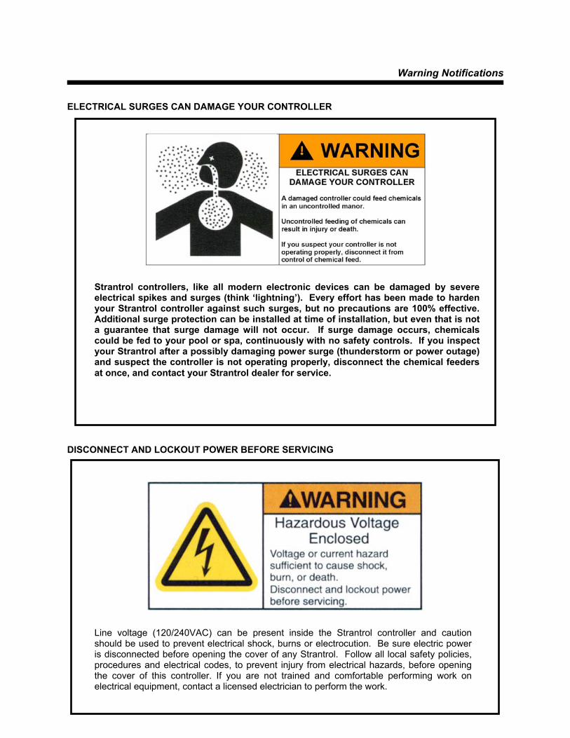
Strantrol controllers, like all modern electronic devices can be damaged by severeelectrical spikes and surges (think ‘lightning’). Every effort has been made to hardenyour Strantrol controller against such surges, but no precautions are 100% effective.Additional surge protection can be installed at time of installation, but even that is nota guarantee that surge damage will not occur. If surge damage occurs, chemicalscould be fed to your pool or spa, continuously with no safety controls. If you inspectyour Strantrol after a possibly damaging power surge (thunderstorm or power outage)and suspect the controller is not operating properly, disconnect the chemical feedersat once, and contact your Strantrol dealer for service.
ELECTRICAL SURGES CAN DAMAGE YOUR CONTROLLER DISCONNECT AND LOCKOUT POWER BEFORE SERVICING
Line voltage (120/240VAC) can be present inside the Strantrol controller and caution should be used to prevent electrical shock, burns or electrocution. Be sure electric power is disconnected before opening the cover of any Strantrol. Follow all local safety policies, procedures and electrical codes, to prevent injury from electrical hazards, before opening the cover of this controller. If you are not trained and comfortable performing work on electrical equipment, contact a licensed electrician to perform the work.
Technical Guide
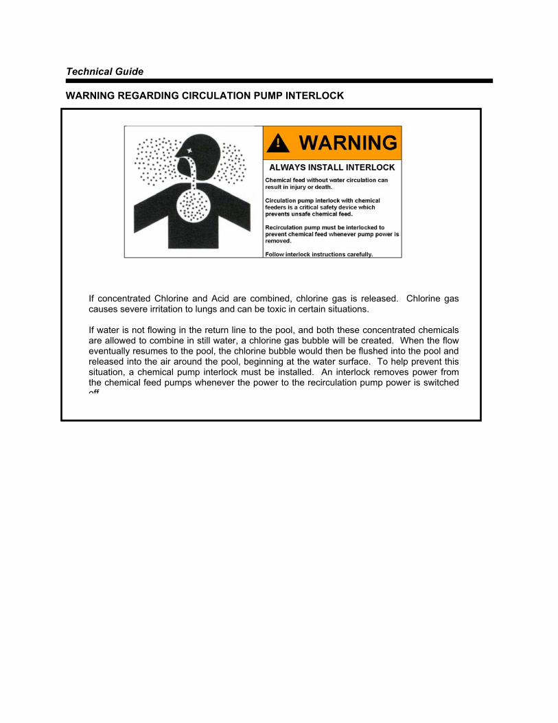
WARNING REGARDING CIRCULATION PUMP INTERLOCK
If concentrated Chlorine and Acid are combined, chlorine gas is released. Chlorine gas causes severe irritation to lungs and can be toxic in certain situations.
If water is not flowing in the return line to the pool, and both these concentrated chemicals are allowed to combine in still water, a chlorine gas bubble will be created. When the flow eventually resumes to the pool, the chlorine bubble would then be flushed into the pool and released into the air around the pool, beginning at the water surface. To help prevent this situation, a chemical pump interlock must be installed. An interlock removes power from the chemical feed pumps whenever the power to the recirculation pump power is switched off
Warning Notifications
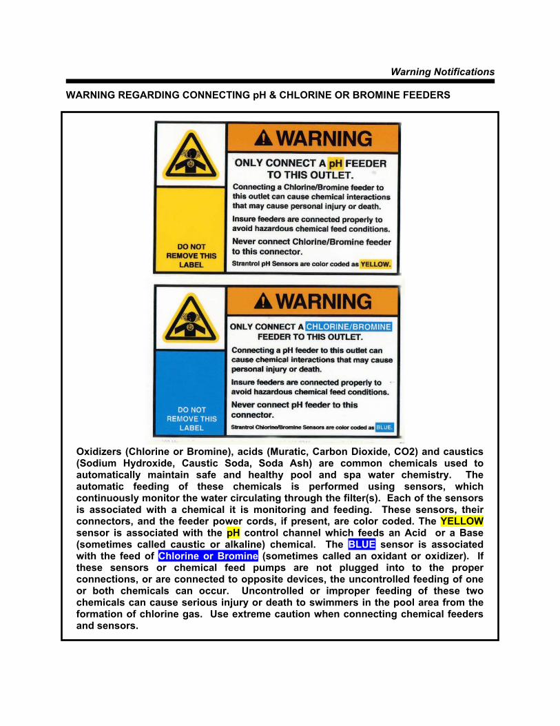
WARNING REGARDING CONNECTING pH & CHLORINE OR BROMINE FEEDERS
Oxidizers (Chlorine or Bromine), acids (Muratic, Carbon Dioxide, CO2) and caustics(Sodium Hydroxide, Caustic Soda, Soda Ash) are common chemicals used toautomatically maintain safe and healthy pool and spa water chemistry. Theautomatic feeding of these chemicals is performed using sensors, whichcontinuously monitor the water circulating through the filter(s). Each of the sensorsis associated with a chemical it is monitoring and feeding. These sensors, theirconnectors, and the feeder power cords, if present, are color coded. The YELLOWsensor is associated with the pH control channel which feeds an Acid or a Base(sometimes called caustic or alkaline) chemical. The BLUE sensor is associatedwith the feed of Chlorine or Bromine (sometimes called an oxidant or oxidizer). Ifthese sensors or chemical feed pumps are not plugged into to the properconnections, or are connected to opposite devices, the uncontrolled feeding of oneor both chemicals can occur. Uncontrolled or improper feeding of these twochemicals can cause serious injury or death to swimmers in the pool area from theformation of chlorine gas. Use extreme caution when connecting chemical feedersand sensors.

Mounting the System5F
Chapter 1-1
Fig 1.1
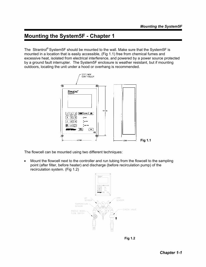
Mounting the System5F - Chapter 1 The Strantrol® System5F should be mounted to the wall. Make sure that the System5F is mounted in a location that is easily accessible, (Fig 1.1) free from chemical fumes and excessive heat, isolated from electrical interference, and powered by a power source protected by a ground fault interrupter. The System5F enclosure is weather resistant, but if mounting outdoors, locating the unit under a hood or overhang is recommended. The flowcell can be mounted using two different techniques: • Mount the flowcell next to the controller and run tubing from the flowcell to the sampling
point (after filter, before heater) and discharge (before recirculation pump) of the recirculation system. (Fig 1.2)
Fig 1.2

Technical Guide
Chapter 1-2
• Mount the flowcell next to the sampling point (after filter, before heater) of the recirculation system and run wires to the System5F using a Signal Transmitter (refer to Signal Transmitter). (Fig 1.3)
Fig 1.3
Plumbing Flowcell
Chapter 2-1
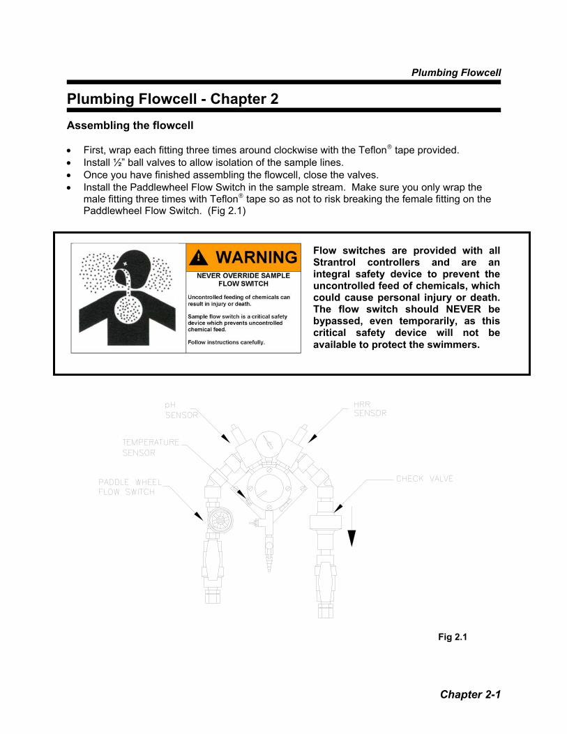
Plumbing Flowcell - Chapter 2 Assembling the flowcell • First, wrap each fitting three times around clockwise with the Teflon® tape provided. • Install ½” ball valves to allow isolation of the sample lines. • Once you have finished assembling the flowcell, close the valves. • Install the Paddlewheel Flow Switch in the sample stream. Make sure you only wrap the
male fitting three times with Teflon® tape so as not to risk breaking the female fitting on the Paddlewheel Flow Switch. (Fig 2.1)
Fig 2.1
Flow switches are provided with all Strantrol controllers and are an integral safety device to prevent the uncontrolled feed of chemicals, which could cause personal injury or death. The flow switch should NEVER be bypassed, even temporarily, as this critical safety device will not be available to protect the swimmers.

Technical Guide
Chapter 2-2
Plumbing the flowcell • Half-inch tubing is recommended for sample stream pickup and return. We have included
two connector fittings with the flowcell if needed. • For the sampling point of the flowcell, tap downstream (after) of filter and upstream (before)
of heater and chemical injection points. • For the discharge point of the flowcell, tap upstream (before) of recirculation pump. (Fig 2.2) • Remove the cap to the pH and HRR sensors, clean tips with a toothbrush and dish soap
and then a light acid. • Screw pH, HRR and Temperature sensors into flowcell. (Fig 2.1)
Fig 2.2
If a vacuum is created in the watercirculation line and no anti-siphondevice is installed on the chemicalfeeders, potentially hazardousconcentrations of chemicals can bedrawn into the pool or spa. Always useinjection check valves and anti-siphonvalves in the chemical feed lines toprevent this situation from occurring.
WARNING: FAILURE TO INCORPORATE A FLOW SWITCH INTO THE SAMPLE STREAM OF YOUR CHEMICAL CONTROL SYSTEM CAN RESULT IN INJURY OR DEATH TO SWIMMERS IN OR AROUND THE POOL, IF THE RECIRCULATION PUMP SHOULD FAIL OR IS SHUT DOWN.
CAUTION: ANTI-SIPHON DEVICES MUST BE INSTALLED TO INSURE THAT UNCONTROLLED FEED OF CHEMICAL WILL NOT OCCUR IF A VACUUM IS CREATED IN THE RETURN LINE.
pH FEED DEVICEINJECTION POINT
Cl/Br FEED DEVICEINJECTION POINT
WARNING: TO AVOID THE CREATION OF HAZARDOUS CHEMICAL CONCENTRATIONS, NEVER COMBINE CHEMICALS INTO A COMMON INJECTION LINE. ALWAYS SEPARATE THE INDIVIDUAL CHEMICAL INJECTION POINTS BY AT LEAST 12 INCHES. CHEMICAL INJECTION POINTS MUST BE DOWNSTREAM FROM ANY HEATERS AND THE LAST ITEMS IN THE RETURN LINE TO THE POOL OR SPA.
WARNING: INSURE SAMPLE STREAM IS INSTALLED TO ASSURE THE FLOW SWITCH STOPS WHENEVER WATER IS NOT FLOWING PAST CHEMICAL INJECTION POINTS.THIS MUST INCLUDE FILTER BACKWASH AND LOSS OF PRIME IN THE MAIN WATER RECIRCULATION PUMP. BE SURE TO TEST THAT THE FLOW SWITCH STOPS WITHIN 20 SECONDS AND THE FLOW ALARM ACTIVATES, WHENEVER FLOW IS INTERRUPTED TO THE RETURN LINE. THE FLOW SWITCH MUST BE CHECKED PERIODICALLY (AT LEAST MONTHLY).

Plumbing Flowcell
Chapter 2-3
Checking the Flowcell • Open the sample stream valves and check for leaks. • Make sure the compound pressure gauge is showing a positive and steady pressure. • Adjust the valves or relocate point at which the sample stream is connected to the
recirculation system to ensure positive and steady pressure. • Allow the sensors to rinse in the sample flowcell while you do the wiring. • Open wet-test valve and make sure that it generates a vigorous stream.
If flow switch does not stop and remainstopped during backwash, no-flow, or verylow flow conditions, the controller cannotprevent the uncontrolled feed of chemicals,which could cause personal injury ordeath. Testing of the flow switch installation isessential to assure the flow switch stops,remains stopped, and controller shows“NO-FLOW ALARM” within 20 seconds,whenever filter is in backwash orcirculation flow stops. If the flow switchdoes not stop completely, plumbingcorrections or the installation of additionalsafeguards will be necessary to avoiduncontrolled chemical feed.


System Startup
Chapter 3-1
System Startup - Chapter 3 System5F Board Types This page describes connections that your Strantrol representative
needs to make in order for your System5F to function. Connections are presented in order of board type (or location):
Key
Description
4
Modem Board (for Serial/Output connections) (Fig 3.1)
3
Output Board(4-20 mA) (Fig 3.1) (Optional)
2
Input Board (Fig 3.1)
1
CPU Board (Fig 3.1)
Fig 3.1
Technical Guide
Chapter 3-2
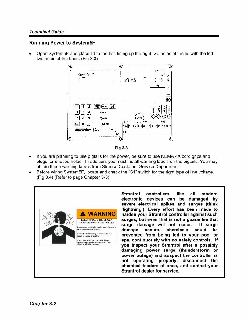
Running Power to System5F • Open System5F and place lid to the left, lining up the right two holes of the lid with the left
two holes of the base. (Fig 3.3) • If you are planning to use pigtails for the power, be sure to use NEMA 4X cord grips and
plugs for unused holes. In addition, you must install warning labels on the pigtails. You may obtain these warning labels from Stranco Customer Service Department.
• Before wiring System5F, locate and check the “S1” switch for the right type of line voltage. (Fig 3.4) (Refer to page Chapter 3-5)
Fig 3.3
Strantrol controllers, like all modernelectronic devices can be damaged bysevere electrical spikes and surges (think‘lightning’). Every effort has been made toharden your Strantrol controller against suchsurges, but even that is not a guarantee thatsurge damage will not occur. If surgedamage occurs, chemicals could beprevented from being fed to your pool orspa, continuously with no safety controls. Ifyou inspect your Strantrol after a possiblydamaging power surge (thunderstorm orpower outage) and suspect the controller isnot operating properly, disconnect thechemical feeders at once, and contact yourStrantrol dealer for service.

System Startup
Chapter 3-3
Locate Terminal labeled “TB5”. • Run 120VAC, 60Hz, 15 AMP surge protected Line (Black) to terminal labeled “Line”. (Both
“Line” terminals are connected.) • Run Ground (Green) to terminal labeled “Ground”. (All three “Ground” terminals are
connected.) • Run Neutral (White) to terminal labeled “Neutral”. (All three “Neutral” terminals are connected.) (Fig 3.5)
Fig 3.4
Fig 3.5

Technical Guide
Chapter 3-4
CPU Board Connections
Terminal
Description
Comments/Notes
1 Connects to face panel board terminal 1 (RS422 A)
2 Connects to face panel board terminal 2 (RS422B)
3 Connects to face panel board terminal 3 (RS422 Y)
4 Connects to face panel board terminal 4 (RS422 Z)
5 Connects to face panel board terminal 5 (RS422 V+)
TB7
6 Connects to face panel board terminal 6 (RS422 GND)
TB7 provides wiring positions for connection to the user interface. Terminals 1 through 6 should be connected to TB1 on the user interface in the same order. (This cable may be extended up to 4000 feet by using the remote interface kit.)
7 AC Line (Main) (Black) 8 AC Line
One line terminal is used for power in. 120VAC, 60Hz, 15 AMP surge protected
9 Earth Ground (Green) 10 Earth Ground 11 Earth Ground 12 AC Neutral (White) 13 AC Neutral
TB5
14 AC Neutral
Used as Main Power, Earth, and Neutral connections. NEVER connect controller power neutral to pump power neutral. Warranty will be voided!
If the chemical feeders are connected to a wall outlet, the safety devices integral to your Strantrol controller, and to the safe feeding of chemicals, will be bypassed. It is very important that the chemical feeders are connected to the controller and never to a wall outlet. If the chemical feeders are connected to a wall outlet and feeding continuously, when the flow of water to the pool stops due to filter backwash, the circulation pump losing prime or other causes, potentially hazardous concentrations of chemicals can be fed into pool or spa.

System Startup
Chapter 3-5
There are two common terminals on TB1, terminals 16 & 19. Each one is a common for two of the four dry-contact relays. The other four terminals (15,17,18, and 20) on TB1, are the remaining output contacts for those relays.
15 Relay Output 1 Switched AC LOAD from Relay #1 (default configuration is pH control)
Oxidizers (Chlorine or Bromine), acids (Muratic, Carbon Dioxide, CO2) and caustics (Sodium Hydroxide, Caustic Soda, Soda Ash) are common chemicals used to automatically maintain safe and healthy pool and spa water chemistry. The automatic feeding of these chemicals is performed using sensors, which continuously monitor the water circulating through the filter(s). Each of the sensors is associated with a chemical it is monitoring and feeding. These sensors, their connectors, and the feeder power cords, if present, are color coded. The YELLOW sensor is associated with the pH control channel which feeds an Acid or a Base (sometimes called caustic or alkaline) chemical. If this sensor or chemical feed pumps are not plugged into to the proper connections, or are connected to opposite devices, the uncontrolled feeding of one or both chemicals can occur. Uncontrolled or improper feeding of these two chemicals can cause serious injury or death to swimmers in the pool area from the formation of chlorine gas. Use extreme caution when connecting chemical feeders and sensors.
16 Common AC Power for Relay Output 1 & 2
LINE Power to Relay 1 & 2 (MAINS) which must be interlocked with main water recirculation pump control relay (motor starter aux. contact) to disable chemical feed when main recirculation pump is disabled.
17 Relay Output 2 Switched AC LOAD from Relay # 2 (default configuration is Sensor Wash)
TB1 18 Relay Output 3 Switched AC LOAD from Relay # 3 (default
configuration is Chlorine/Bromine)
Technical Guide
Chapter 3-6
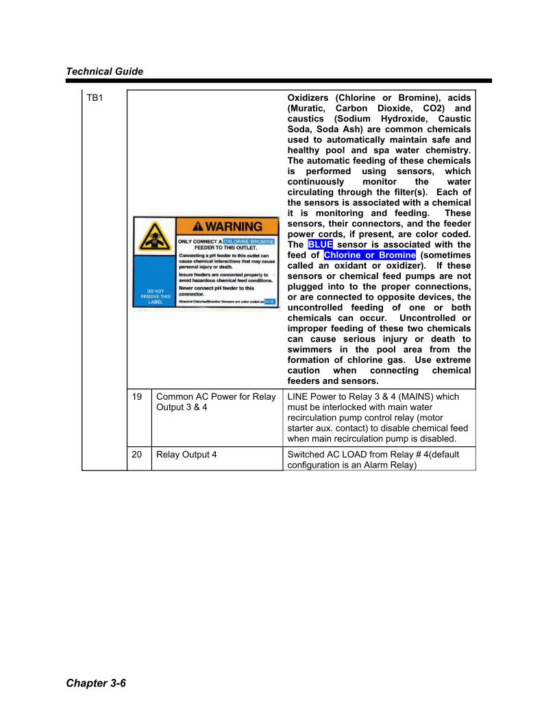
Oxidizers (Chlorine or Bromine), acids (Muratic, Carbon Dioxide, CO2) and caustics (Sodium Hydroxide, Caustic Soda, Soda Ash) are common chemicals used to automatically maintain safe and healthy pool and spa water chemistry. The automatic feeding of these chemicals is performed using sensors, which continuously monitor the water circulating through the filter(s). Each of the sensors is associated with a chemical it is monitoring and feeding. These sensors, their connectors, and the feeder power cords, if present, are color coded. The BLUE sensor is associated with the feed of Chlorine or Bromine (sometimes called an oxidant or oxidizer). If these sensors or chemical feed pumps are not plugged into to the proper connections, or are connected to opposite devices, the uncontrolled feeding of one or both chemicals can occur. Uncontrolled or improper feeding of these two chemicals can cause serious injury or death to swimmers in the pool area from the formation of chlorine gas. Use extreme caution when connecting chemical feeders and sensors.
19 Common AC Power for Relay Output 3 & 4
LINE Power to Relay 3 & 4 (MAINS) which must be interlocked with main water recirculation pump control relay (motor starter aux. contact) to disable chemical feed when main recirculation pump is disabled.
TB1
20 Relay Output 4 Switched AC LOAD from Relay # 4(default configuration is an Alarm Relay)
System Startup
Chapter 3-7
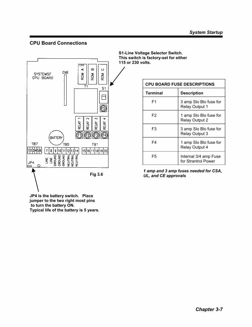
CPU Board Connections
S1-Line Voltage Selector Switch. This switch is factory-set for either 115 or 230 volts.
CPU BOARD FUSE DESCRIPTIONS Terminal
Description
F1
3 amp Slo Blo fuse for Relay Output 1
F2
1 amp Slo Blo fuse for Relay Output 2
F3
3 amp Slo Blo fuse for Relay Output 3
F4
1 amp Slo Blo fuse for Relay Output 4
F5
Internal 3/4 amp Fuse for Strantrol Power
JP4 is the battery switch. Place jumper to the two right most pins to turn the battery ON. Typical life of the battery is 5 years.
Fig 3.6
CN5
1 amp and 3 amp fuses needed for CSA, UL, and CE approvals

Technical Guide
Chapter 3-8
Wiring Devices to Relays in the System5F WARNING! Controller power and feed device power must be separated. This setup reduces noise inside the controller and eliminates controller damage due to transient spikes from the pumps.
NEVER connect controller power neutral to feed device power neutral or WARRANTY WILL BE VOID! • Relays 1 through 4 are already configured for specific functions but can be reconfigured for
your application.
Relay 1 pH Feed Down Relay 2 Sensor Wash Relay 3 Chlorine Feed Relay 4 Audible or Visual Alarm
If the chemical feeders are connected to awall outlet, the safety devices integral toyour Strantrol controller, and to the safefeeding of chemicals, will be bypassed. It isvery important that the chemical feeders areconnected to the controller and never to awall outlet. If the chemical feeders areconnected to a wall outlet and feedingcontinuously, when the flow of water to thepool stops due to filter backwash, thecirculation pump losing prime or othercauses, potentially hazardous concen-trations of chemicals can be fed into pool orspa.
Line voltage (120/240VAC) can be present inside the Strantrol controller and caution should be used to prevent electrical shock, burns or electrocution. Be sure electric power is disconnected before opening the cover of any Strantrol. Follow all local safety policies, procedures and electrical codes, to prevent injury from electrical hazards, before opening the cover of this controller. If you are not trained and comfortable performing work on electrical equipment, contact a licensed electrician to perform the work.

System Startup
Chapter 3-9
• Other relay functions are below.
Control Action Factory Default pH Feed - Down Relay 1 pH Feed - Up Sensor Wash Relay 2 Chlorine/Bromine Relay 3 Alarm Relay 4 Dechlorination Superchlorination Heater Chlorine/Bromine Boost System Ozone The relays can be interchanged in any order, including multiple relays controlling the same function. Note: If two relays control the same function, they will trigger at the same setpoint.
• Locate Terminal labeled “TB1” in the System5F. (Fig. 3.7) • Connect device line to terminal labeled “N.O.#” (the # corresponds to the Relay #).
PREVENT ELECTROCUTION
DISCONNECT ALL SUPPLY CONNECTIONS BEFORE SERVICING THIS APPLIANCE HAS UP TO 3 SUPPLY CONNECTIONS
CAUTION: FOR CHANGE OF OPERATING VOLTAGE, REFER TO AUTHORIZED SERVICE PERSON. ATTENTION: POUR ADAPTER L’APPAREIL À LA TENSION D’ALIMENTATION, COMMUNIQUER AVEC UN TECHNICIEN AUTORISÉ. CAUTION: THIS UNIT MAY HAVE UP TO 3 POWER SUPPLY CONNECTIONS. DISCONNECT ALL POWER SUPPLY CONNECTIONS BEFORE SERVICING. ATTENTION: CET APPAREIL REÇOIT PLUSIEURS ALIMENTATIONS. LE DÉBRANCHMENT DES CORDONS NE SUFFIT PAS NÉCESSAIREMENT À LE METTRE HORS TENSION. RELAY WIRING MUST HAVE MINIMUM RATINGS OF 105°C, 600VAC, 14AWG AND HAVE INSULATION OF PVC TO COMPLY WITH THE MAXIMUM LOAD RATINGS FOR THIS EQUIPMENT. CONSULT YOUR NATIONAL OR LOCAL ELECTRICAL CODES FOR PROPER WIRING OF LESSER LOADS.
Technical Guide
Chapter 3-10
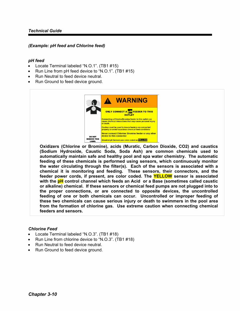
(Example: pH feed and Chlorine feed) pH feed • Locate Terminal labeled “N.O.1”. (TB1 #15) • Run Line from pH feed device to “N.O.1”. (TB1 #15) • Run Neutral to feed device neutral. • Run Ground to feed device ground. Chlorine Feed • Locate Terminal labeled “N.O.3”. (TB1 #18) • Run Line from chlorine device to “N.O.3”. (TB1 #18) • Run Neutral to feed device neutral. • Run Ground to feed device ground.
Oxidizers (Chlorine or Bromine), acids (Muratic, Carbon Dioxide, CO2) and caustics(Sodium Hydroxide, Caustic Soda, Soda Ash) are common chemicals used toautomatically maintain safe and healthy pool and spa water chemistry. The automaticfeeding of these chemicals is performed using sensors, which continuously monitorthe water circulating through the filter(s). Each of the sensors is associated with achemical it is monitoring and feeding. These sensors, their connectors, and thefeeder power cords, if present, are color coded. The YELLOW sensor is associatedwith the pH control channel which feeds an Acid or a Base (sometimes called causticor alkaline) chemical. If these sensors or chemical feed pumps are not plugged into tothe proper connections, or are connected to opposite devices, the uncontrolledfeeding of one or both chemicals can occur. Uncontrolled or improper feeding ofthese two chemicals can cause serious injury or death to swimmers in the pool areafrom the formation of chlorine gas. Use extreme caution when connecting chemicalfeeders and sensors.
System Startup
Chapter 3-11
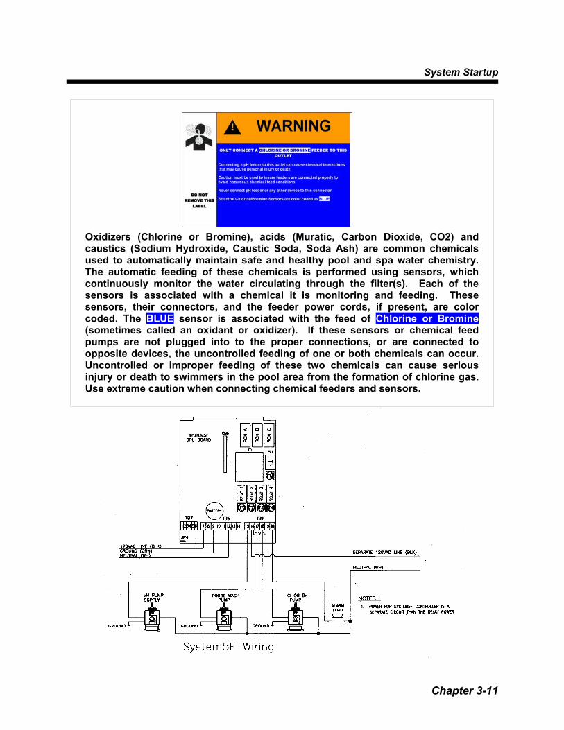
Oxidizers (Chlorine or Bromine), acids (Muratic, Carbon Dioxide, CO2) andcaustics (Sodium Hydroxide, Caustic Soda, Soda Ash) are common chemicalsused to automatically maintain safe and healthy pool and spa water chemistry.The automatic feeding of these chemicals is performed using sensors, whichcontinuously monitor the water circulating through the filter(s). Each of thesensors is associated with a chemical it is monitoring and feeding. Thesesensors, their connectors, and the feeder power cords, if present, are colorcoded. The BLUE sensor is associated with the feed of Chlorine or Bromine(sometimes called an oxidant or oxidizer). If these sensors or chemical feedpumps are not plugged into to the proper connections, or are connected toopposite devices, the uncontrolled feeding of one or both chemicals can occur.Uncontrolled or improper feeding of these two chemicals can cause seriousinjury or death to swimmers in the pool area from the formation of chlorine gas.Use extreme caution when connecting chemical feeders and sensors.

Technical Guide
Chapter 3-12
Connecting Flowcell to System5F pH, HRR and Temperature Sensors • Plug pH sensor into the BNC jack on the left side of the System5F by twisting it a quarter of
a turn to lock it. • Plug HRR sensor into the BNC jack on the right side of the System5F by twisting it a quarter
of a turn to lock it. • Use a NEMA 4X cord grip to insert the Temperature Sensor cable into the System5F. • Locate the Input Board. (Fig. 3.10) • Locate “+Temp-” in the Terminal labeled TB1. (Fig. 3.11) • Connect the white wire to TB1 position 3. • Connect the black wire to TB1 position 4. Water Ground • Locate the Input Board. (Fig 3.10) • Locate “W.Gnd” in the Terminal labeled TB1. (Fig 3.11) • Locate the stainless steel grounding screw provided as a part of the Flowcell. • Using a recommended 18 gauge wire. • Connect the stainless steel grounding screw to “W.Gnd” in TB1 position 1. Flow Switch
• Locate the Input Board (Fig 3.10) • Locate “Flow”, “V+”, “V-” in the Terminal labeled TB1. (Fig. 3.11) • Locate the Flow Switch from the flowcell. • Connect the White wire to “Flow” in TB1 position 5. • Connect the Red wire to “V+” in TB1 position 6. • Connect the Black wire to “V-” in TB1 position 7.
Flow switches are provided with all Strantrol controllers and are an integral safety device to prevent the uncontrolled feed of chemicals, which could cause personal injury or death. The flow switch should NEVER be bypassed, even temporarily, as this critical safety device will not be available to protect the swimmers.

System Startup
Chapter 3-13
Optional: Signal Transmitter • Locate Input Board (Fig. 3.10) • Locate Switch labeled S6 just above TB1. (Fig. 3.11) • S6 must be in the up position. (Fig. 3.12) • Locate the Terminal labeled JP1 in the Signal Transmitter. • Connect “Flow” on the Input Board to JP1 position 5. • Connect “V+” on the Input Board to JP1 position 1. • Connect “V-“ on the Input Board to JP1 position 2. • Connect “1Pamp” on the Input Board to JP1 position 3. • Connect “Pamp2” on the Input Board to JP1 position 4.
Fig. 3.10 & Fig. 3.11
If flow switch dos not stop and remain stopped during backwash, no-flow, or very low flow conditions, the controller cannot prevent the uncontrolled feed of chemicals, which could cause personal injury or death.

Technical Guide
Chapter 3-14
System5F Input Board Signal Transmitter Flow (TB1 position 5) JP1 position 5 V+ (TB1 position 6) JP1 position 1 V- (TB1 position 7) JP1 position 2 1Pamp (TB1 position 8) JP1 position 3 Pamp2 (TB1 position 9) JP1 position 4
• Connect the White wire from the Flow Switch to JP2 position 7 in the Signal Transmitter. • Connect the Red wire from the Flow Switch to JP2 position 6 in the Signal Transmitter. • Connect the Black wire from the Flow Switch to JP2 position 8 in the Signal Transmitter. • Plug pH sensor into the BNC jack on the left side of the Signal Transmitter by twisting it a
quarter of a turn to lock it. • Plug HRR sensor into the BNC jack on the right side of the Signal Transmitter by twisting it a
quarter of a turn to lock it. • Connect the Temperature sensor to the terminals on the lid of the Signal Transmitter. • Connect the terminals of the lid to the Temperature TB1 positions 3 & 4 on the Input Board. • Make sure the polarity is correct. • White in “+Temp” (TB1 position 3). • Black in “Temp-” (TB1 position 4). • The Signal Transmitter is just a junction box for the Temperature Sensor.
Fig 3.12
System Startup
Chapter 3-15
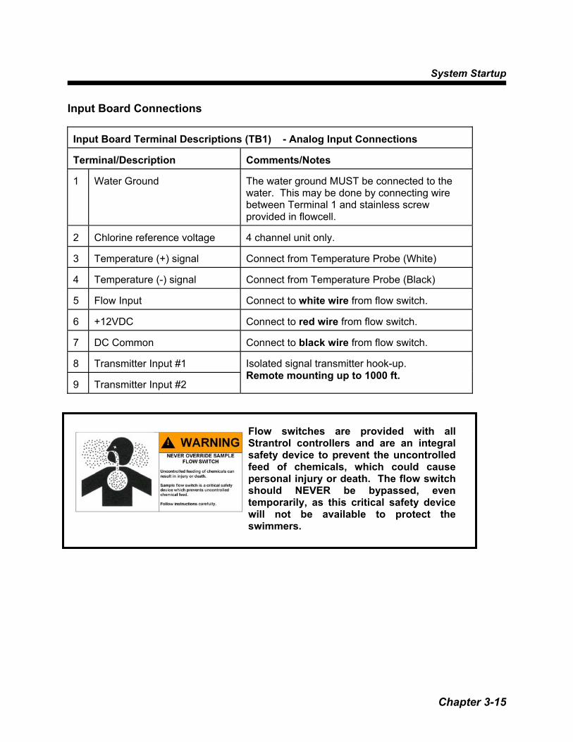
Input Board Connections Input Board Terminal Descriptions (TB1) - Analog Input Connections Terminal/Description
Comments/Notes
1
Water Ground
The water ground MUST be connected to the water. This may be done by connecting wire between Terminal 1 and stainless screw provided in flowcell.
2
Chlorine reference voltage
4 channel unit only.
3
Temperature (+) signal
Connect from Temperature Probe (White)
4
Temperature (-) signal
Connect from Temperature Probe (Black)
5
Flow Input
Connect to white wire from flow switch.
6
+12VDC
Connect to red wire from flow switch.
7
DC Common
Connect to black wire from flow switch.
8
Transmitter Input #1
9
Transmitter Input #2
Isolated signal transmitter hook-up. Remote mounting up to 1000 ft.
Flow switches are provided with all Strantrol controllers and are an integral safety device to prevent the uncontrolled feed of chemicals, which could cause personal injury or death. The flow switch should NEVER be bypassed, even temporarily, as this critical safety device will not be available to protect the swimmers.

Technical Guide
Chapter 3-16
Input Board Connections INPUT BOARD PUSH BUTTONS (MOMENTARY CONTACT) Switch #
Description
S1
Manual Override for Relay 1
S2
Manual Override for Relay 2
S3
Manual Override for Relay 3
S4
Manual Override for Relay 4
S1 through S4 will be used only by authorized personnel during installation.
INPUT BOARD S5 POSITIONS / DESCRIPTIONS Position Description 1 ON Removes ppm reading
OFF Normal display 2 Not Used 3 European Date. ON=dd/mm/yy
English Date. OFF=mm/dd/yy
4 Not Used 5 Direct / Modem selection
OFF = Direct ON = Modem (or voice)
6 Voice Modem. ON = voice modem OFF = No voice modem
7 Factory Use Only 8 Factory Use Only
Fig 3.14

System Startup
Chapter 3-17
Output Board 4-20 mA Connections
All output signals are 4-20 mA. Output connections are made to TB1. Output signals may be for either: Control and/or
Recording.
INPUT BOARD NOTES
Description
Comments/Notes
CN2 Connector for BNC inputs from pH/HRR sensors
See S6 below and use input terminal connections if using a signal transmitter.
S5
Main Dip Switch Bank
S6
Determines whether the pH/HRR sensor inputs are from the BNC connector or from a remote signal transmitter.
Set this switch UP to use the signal transmitter input. Set this switch DOWN to use the BNC input.
Fig 3.15

Technical Guide
Chapter 3-18
Output Board 4-20 mA Connections
4-20 mA OUTPUT BOARD TERMINAL DESCRIPTIONS
TERMINAL DESCRIPTION DEFAULT VALUES
1 (+) 4-20 mA output signal for Channel #1 Recorder pH 6.0 - 9.0
2 (-) 4-20 mA output signal for Channel #1 Recorder
3 (+) 4-20 mA output signal for Channel #2 Recorder HRR 0 -1000 mV
4 (-) 4-20 mA output signal for Channel #2 Recorder
5 (+) 4-20 mA output signal for Channel #3 Recorder ppm 0 - 20 ppm
6 (-) 4-20 mA output signal for Channel #3 Recorder
7 (+) 4-20 mA output signal for Channel #4 Recorder Temperature 60 - 100
8 (-) 4-20 mA output signal for Channel #4 Recorder
System Startup
Chapter 3-19
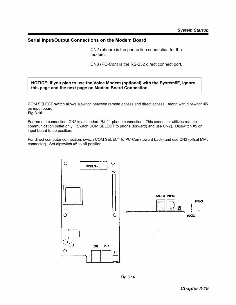
Serial Input/Output Connections on the Modem Board CN2 (phone) is the phone line connection for the
modem. CN3 (PC-Con) is the RS-232 direct connect port.
COM SELECT switch allows a switch between remote access and direct access. Along with dipswitch #5 on input board. Fig 3.16 For remote connection, CN2 is a standard RJ-11 phone connection. This connector utilizes remote communication outlet only. (Switch COM SELECT to phone (forward) and use CN2). Dipswitch #5 on input board to up position. For direct computer connection, switch COM SELECT to PC-Con (toward back) and use CN3 (offset MMJ connector). Set dipswitch #5 to off position.
NOTICE: If you plan to use the Voice Modem (optional) with the System5F, ignore this page and the next page on Modem Board Connection.
Fig 3.16
Technical Guide
Chapter 3-20
Printer Board Connections (Optional)
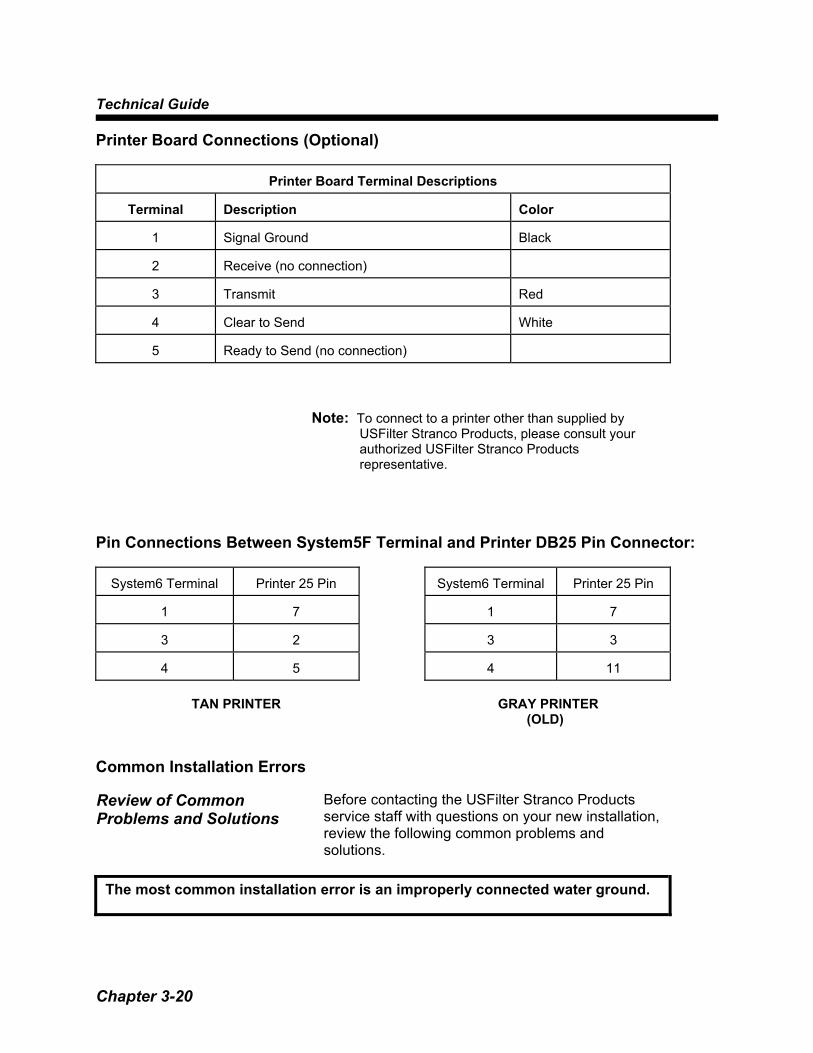
Printer Board Terminal Descriptions
Terminal
Description
Color
1
Signal Ground
Black
2
Receive (no connection)
3
Transmit
Red
4
Clear to Send
White
5
Ready to Send (no connection)
Note: To connect to a printer other than supplied by USFilter Stranco Products, please consult your authorized USFilter Stranco Products representative.
Pin Connections Between System5F Terminal and Printer DB25 Pin Connector:
System6 Terminal
Printer 25 Pin
System6 Terminal
Printer 25 Pin
1
7
1
7
3
2
3
3
4
5
4
11
TAN PRINTER GRAY PRINTER (OLD) Common Installation Errors Review of Common Problems and Solutions
Before contacting the USFilter Stranco Products service staff with questions on your new installation, review the following common problems and solutions.
The most common installation error is an improperly connected water ground.

System Startup
Chapter 3-21
The water ground must be connected to the proper terminal in the controller and to the connector on the flowcell.
Feed devices will not start The relays are dry contact. To activate a feed
device, power must be provided to the relay contacts. To provide 120 VAC to all four relays: • Connect a jumper wire from the CPU board TB5
#7 or #8 (both are AC line) to TB1 #16 (Com 1,2). Connect another jumper from TB1 #16 to TB1 #19 (Com 3,4).
WARNING: This will bypass the interlocking
protection and should only be done for troubleshooting purposes.
• Consult the wiring diagram for correct wiring. Fig 3.12
The HRR or pH Displays Fluctuate Rapidly
• Check the water ground connection, both in the controller and on the flowcell.
• Connect a signal generator and verify that the SG-700 ground lead is connected.
• Verify that the display matches the signal generator readings.
• Check BNC to input board connections. • Check S6 input switch position. Down (off) for BNC/sensor input, Up (on) for preamp input.
The chlorine reading is WAIT.
If the pH changes more than .08 in one minute, the WAIT message is displayed in place of the ppm reading. It prevents standardization of the chlorine display until pH stabilizes. This wait time may be up to 30 seconds.
Technical Guide
Chapter 3-22
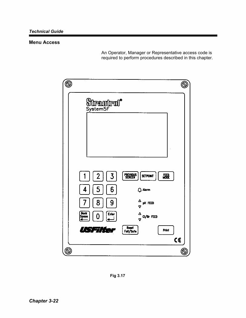
Menu Access
An Operator, Manager or Representative access code is required to perform procedures described in this chapter.
Fig 3.17
System Startup
Chapter 3-23
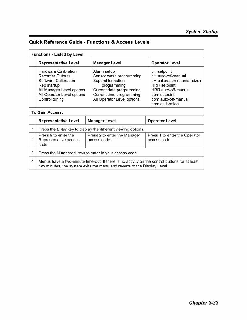
Quick Reference Guide - Functions & Access Levels
Functions - Listed by Level:
Representative Level
Manager Level
Operator Level
Hardware Calibration Recorder Outputs Software Calibration Rep startup All Manager Level options All Operator Level options Control tuning
Alarm setup Sensor wash programming Superchlorination
programming Current date programming Current time programming All Operator Level options
pH setpoint pH auto-off-manual pH calibration (standardize) HRR setpoint HRR auto-off-manual ppm setpoint ppm auto-off-manual ppm calibration
To Gain Access:
Representative Level
Manager Level
Operator Level
1
Press the Enter key to display the different viewing options.
2 Press 9 to enter the
Representative access code.
Press 2 to enter the Manager access code.
Press 1 to enter the Operator access code
3
Press the Numbered keys to enter in your access code.
4
Menus have a two-minute time-out. If there is no activity on the control buttons for at least two minutes, the system exits the menu and reverts to the Display Level.

Technical Guide
Chapter 3-24
Data Logging Event The System5F considers changes within its system as
events. Examples of events would be:
• Relays opening and closing • Alarm conditions • Parameter changes
Event Buffer Each time an event occurs, an entry is made in the
event buffer. When an event is stored it received a time stamp. You can, therefore, trace changes to the system to the time the event occurred. The event buffer has room for 1000 entries. When the buffer fills up, the oldest entry is erased to make room for new entries. The SVC program allows you to download the event buffer to a PC hard drive or a floppy diskette. If you download the event buffer before it fills up, you will have a PC-compatible record of the event history saved. In the meantime, the System5F will erase the oldest entries to make room for new ones. How frequently you schedule your downloads depends on whether you want to save high resolution or low resolution storage information.
High/Low Resolution Logs
The System5F stores parameter readings at two resolutions simultaneously:
High Resolution, which stores minimum, maximum, average and sample values for the specified time frame.
Low Resolution, which stores minimum, maximum, average and sample values for the specified time frame.

System Startup
Chapter 3-25
High Resolution
Low Resolution
The default time period stores values every:
6 minutes
2 hours
The minimum setting is:
1 minute
1 hour
The maximum setting is:
6 minutes (the default)
4 hours
When using the minimum setting, history is stored for:
9 hours
17 days
When using the maximum setting, history is stored for:
2 days - 6 hours
68 days
When using the default setting, history is stored for:
2 days - 6 hours
34 days
The amount of time that history is stored represents
the maximum amount of time you can schedule downloads. For example, if your high resolution is set at the default, you must download high-resolution data every 2 days -6 hours. If you wait 2 days - 7 hours between downloads, System5F will erase the oldest information in the buffer in order to make room for the new information.
Technical Guide
Chapter 3-26
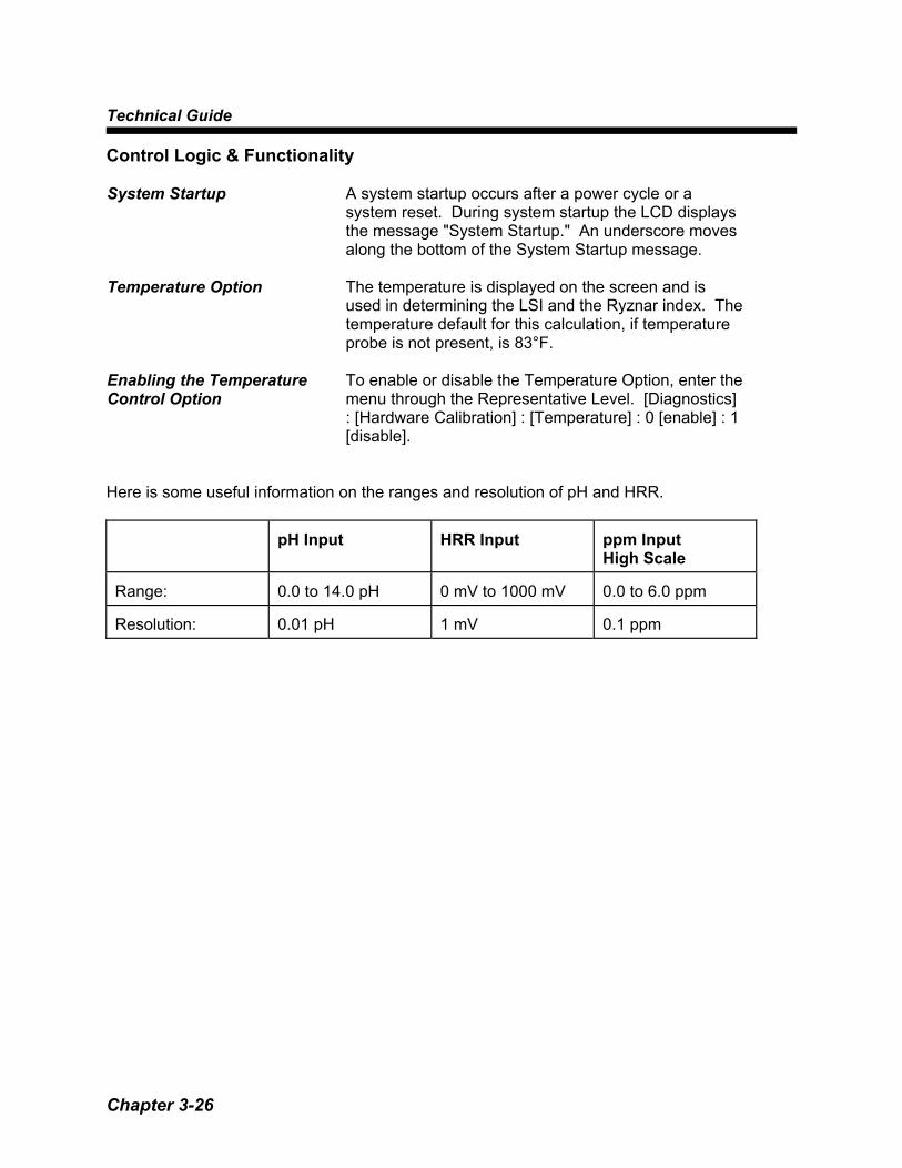
Control Logic & Functionality System Startup A system startup occurs after a power cycle or a
system reset. During system startup the LCD displays the message "System Startup." An underscore moves along the bottom of the System Startup message.
Temperature Option The temperature is displayed on the screen and is
used in determining the LSI and the Ryznar index. The temperature default for this calculation, if temperature probe is not present, is 83°F.
Enabling the Temperature Control Option
To enable or disable the Temperature Option, enter the menu through the Representative Level. [Diagnostics] : [Hardware Calibration] : [Temperature] : 0 [enable] : 1 [disable].
Here is some useful information on the ranges and resolution of pH and HRR.
pH Input
HRR Input
ppm Input High Scale
Range:
0.0 to 14.0 pH
0 mV to 1000 mV
0.0 to 6.0 ppm
Resolution:
0.01 pH
1 mV
0.1 ppm
System Startup
Chapter 3-27
Ozone Option The purpose of the ozone option is to allow control of
an ozonator. The operation of the ozonator relay is basic. The relay is normally closed (i.e. the ozonator is "ON") under normal operation. When the System5F recognizes a high HRR alarm, the relay switches (in other words, the ozonator is "OFF").
Enabling the Ozone Option
1. Enter the menu system using the Representative
access code. 2. Select [Rep Startup]. 3. Select one of the four relays to operate the ozone.
Selecting a relay for ozone enables ozone control on that relay.
4. Adjust HRR High Alarm parameter as needed.
Technical Guide
Chapter 3-28
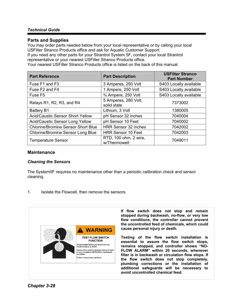
Parts and Supplies You may order parts needed below from your local representative or by calling your local USFilter Stranco Products office and ask for Aquatic Customer Support. If you need any other parts for your Strantrol System 5F, contact your local Strantrol representative or your nearest USFilter Stranco Products office. Your nearest USFilter Stranco Products office is listed on the back of this manual.
Part Reference Part Description USFilter Stranco Part Number
Fuse F1 and F3 3 Amperes, 250 Volt S403 Locally available Fuse F2 and F4 1 Ampere, 250 Volt S403 Locally available Fuse F5 ¾ Ampere, 250 Volt S403 Locally available
Relays R1, R2, R3, and R4 5 Amperes, 280 Volt, solid state 7373002
Battery B1 Lithium, 3 Volt 1380005 Acid/Caustic Sensor Short Yellow pH Sensor 32 inches 7040004 Acid/Caustic Sensor Long Yellow pH Sensor 10 Feet 7040002 Chlorine/Bromine Sensor Short Blue HRR Sensor 32 inches 7042002 Chlorine/Bromine Sensor Long Blue HRR Sensor 10 Feet 7042003
Temperature Sensor RTD, 100 ohm, 2 wire, w/Thermowell 7049011
Maintenance Cleaning the Sensors The System5F requires no maintenance other than a periodic calibration check and sensor cleaning. 1. Isolate the Flowcell, then remove the sensors.
If flow switch does not stop and remainstopped during backwash, no-flow, or very lowflow conditions, the controller cannot preventthe uncontrolled feed of chemicals, which couldcause personal injury or death. Testing of the flow switch installation isessential to assure the flow switch stops,remains stopped, and controller shows “NO-FLOW ALARM” within 20 seconds, wheneverfilter is in backwash or circulation flow stops. Ifthe flow switch does not stop completely,plumbing corrections or the installation ofadditional safeguards will be necessary toavoid uncontrolled chemical feed.

System Startup
Chapter 3-29
2. Clean the tips with HRR Cleaning Solution and a toothbrush. 3. Check Teflon® sealing tape on threads and reinstall sensor. 4. Open valves and let sensors rinse 10 to 15 minutes in sample stream water before
making any adjustments. NOTE: If the sample stream is shut down for more than a short time (particularly in freezing temperatures), remove the sensors from the flowcell and unplug the System5F. Store the sensors in a heated, secure area, with the sensor caps in place or with the tips immersed in any small container of water to prevent them from drying out.


Control Tuning
Chapter 4- 1
Control Tuning - Chapter 4
pH Control Options
pH Feed-down
pH Feed-up
Feed-down means that when chemical is fed, the pH lowers.
Feed-up means that when chemical is fed, the pH rises.
Hook-up the pH feed device to appropriate relay as shown in the wiring diagrams.
Hook-up the pH feed device to appropriate relay as shown in the wiring diagrams. (Reprogram Relay)
1
Enter the menu system using a Manager or Representative access code.
2
Select [pH SETUP]:[pH feeddn or feedup Mode]. Select whether the pH control is on/off[0] or proportional[1].
3
With on/off control (and pH feed-down), whenever the pH is above the setpoint, the pH feed device will be [on] until setpoint is reached.
With on/off control (and pH feed-up), whenever the pH is below the setpoint, the pH feed device will be [on] until setpoint is reached.
4
Select [pH prop span](proportional span). If you selected on/off control, ignore this step. If you selected proportional mode, select the control proportional span. The proportional span defines the "window" of control for the pH chemicals.
5
Settings Setpoint 7.5 Proportional span .5 Input pH Value Feed device Duty Cycle
8.0 100% 7.8 60% 7.5 0%
Settings Setpoint 7.5 Proportional span .5 Input pH Value Feed device Duty
Cycle 7.0 100% 7.2 60% 7.5 0%
6 Select [pH feed down F/S]. Select [pH feed down F/S]. 7
The fail/safe alarm sets a feed time-out value. If the feed device operates for this period of time without reaching setpoint, a fail/safe alarm is recognized and the control relay is disabled (locked out).
Technical Guide
Chapter 4 - 2
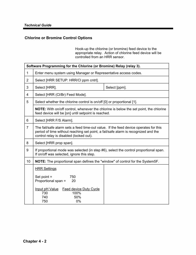
Chlorine or Bromine Control Options
Hook-up the chlorine (or bromine) feed device to the appropriate relay. Action of chlorine feed device will be controlled from an HRR sensor.
Software Programming for the Chlorine (or Bromine) Relay (relay 3). 1
Enter menu system using Manager or Representative access codes.
2
Select [HRR SETUP: HRR/Cl ppm cntrl].
3
Select [HRR].
Select [ppm].
4
Select [HRR (Cl/Br) Feed Mode]. Select whether the chlorine control is on/off [0] or proportional [1].
5
NOTE: With on/off control, whenever the chlorine is below the set point, the chlorine feed device will be [on] until setpoint is reached.
6
Select [HRR F/S Alarm].
7
The fail/safe alarm sets a feed time-out value. If the feed device operates for this period of time without reaching set point, a fail/safe alarm is recognized and the control relay is disabled (locked out).
8
Select [HRR prop span].
9
If proportional mode was selected (in step #6), select the control proportional span. If on/off was selected, ignore this step.
10
NOTE: The proportional span defines the "window" of control for the System5F.
HRR Settings Set point = 750 Proportional span = 20 Input pH Value Feed device Duty Cycle
730 100% 740 50% 750 0%
Control Tuning
Chapter 4- 3
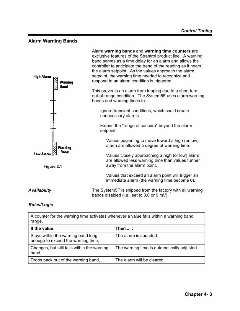
Alarm Warning Bands
Alarm warning bands and warning time counters are exclusive features of the Strantrol product line. A warning band serves as a time delay for an alarm and allows the controller to anticipate the trend of the reading as it nears the alarm setpoint. As the values approach the alarm setpoint, the warning time needed to recognize and respond to an alarm condition is triggered. This prevents an alarm from tripping due to a short term out-of-range condition. The System5F uses alarm warning bands and warning times to:
Ignore transient conditions, which could create unnecessary alarms.
Extend the "range of concern" beyond the alarm setpoint:
Values beginning to move toward a high (or low) alarm are allowed a degree of warning time.
Values closely approaching a high (or low) alarm are allowed less warning time than values further away from the alarm point.
Values that exceed an alarm point will trigger an immediate alarm (the warning time become 0).
Availability The System5F is shipped from the factory with all warning
bands disabled (i.e., set to 0.0 or 0 mV). Rules/Logic
A counter for the warning time activates whenever a value falls within a warning band range.
If the value: Then ... : Stays within the warning band long enough to exceed the warning time, ...
The alarm is sounded.
Changes, but still falls within the warning band, ...
The warning time is automatically adjusted.
Drops back out of the warning band, ... The alarm will be cleared.
Figure 2.1

Technical Guide
Chapter 4 - 4
Example — High Alarm Warning Band For an explanation of high alarm warning bands, follow
the example below.
Scenario pH High Alarm = 8.5 Warning band = 0.5 Current pH reading = 8.2 pH high reading time 5.0 minutes
This current pH reading (8.2) is 60% away from high alarm.
Calculation: (High Alarm - Current Reading) / Warning Band
(8.5 - 8.2) / .5 = .6 = 60% The proportional warning time will be 60% of the standard warning time.
Calculation: % from High Alarm* Warning Time 60% * 5 minutes = 3 minutes
Consequently, if the alarm counter exceeds 3 minutes, a high alarm occurs. If the pH changes to 8.1 (before the 3 minute alarm), then System5F automatically re-adjusts the standard alarm warning time to a new proportional warning time:
Calculation: (High Alarm - Current Reading) / Warning Band (8.5 - 8.1) / .5 = .8 = 80%
% from High Alarm* Warning Time 0.80% * 5 minutes = 4 minutes
In this case, the alarm counter will not reset because the pH changed within the warning band. Remember that the high alarm is the absolute high. Whenever the current reading exceeds the high alarm, a high alarm occurs regardless of any warning band time counters.
Figure 2.2

Control Tuning
Chapter 4- 5
Example — Low Alarm Warning Bands The low alarm warning band is very similar; however,
the warning band is reversed.
Scenario pH High Alarm = 6.0 Warning band = 0.5 Current pH reading = 6.3 pH high reading time 5.0 minutes
If current pH value remains at 6.3 for 3 minutes, a low alarm occurs.
Calculation:
(6.3 - 6.0) / .5 = .6 = 60% away from setpoint 0.60%* 5 minutes = 3 minutes
Figure 2.3


Recorder Outputs
Chapter 5 - 1
Recorder Outputs - Chapter 5 4-20 mA Outputs
The Strantrol System5F two-channel controller is capable of handling two or four analog outputs. Each of the channels can be independently configured for pH, HRR, ppm or temperature from within the menu system. Furthermore, the values corresponding to 4 mA and 20 mA (0-100%) can be specified for each channel, thus making the channel available as either a recorder or control output. All analog channels are configured in the same way.
EXAMPLE: Configure Channel #1 for recording pH from 6.0 to 9.0 1 Enter menu system using Representative access code. 2 Select [RECORDER OUTPUTS: Channel #1 Recorder]. 3 Select, by pressing the corresponding number to the left, which input Channel #1 will
record or control. The choices are pH, HRR, ppm and Temperature. (For this example, choose pH.) Select [RECORDER OUTPUTS: Channel #1 Recorder: Chan #1 Rec]. 4 This is a display only of the current parameter to be recorded or controlled.
5 Select [RECORDER OUTPUTS: Channel #1 Recorder: Chan #1 Rec Min]. 6 Select the minimum value to be recorded or controlled. (Select 6.0 for this
example.) A pH of 6.0 = 4 mA output. 7 Select [RECORDER OUTPUTS: Channel #1 Recorder: Chan #1 Rec Max]. 8 Select the maximum value to be recorded or controlled. (Select 9.0 for this
example.) A pH of 9.0 = 20 mA output.
Channel #1 is now configured to record pH from 6.0 to 9.0. The output signal is the same for control as it is for recording. Consult the factory if using outputs for control.
Technical Guide
Chapter 5 - 2
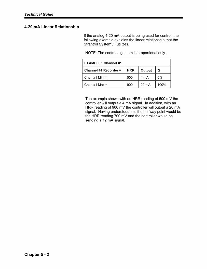
4-20 mA Linear Relationship
If the analog 4-20 mA output is being used for control, the following example explains the linear relationship that the Strantrol System5F utilizes. NOTE: The control algorithm is proportional only.
EXAMPLE: Channel #1 Channel #1 Recorder =
HRR
Output
%
Chan #1 Min =
500
4 mA
0%
Chan #1 Max =
900
20 mA
100%
The example shows with an HRR reading of 500 mV the controller will output a 4 mA signal. In addition, with an HRR reading of 900 mV the controller will output a 20 mA signal. Having understood this the halfway point would be the HRR reading 700 mV and the controller would be sending a 12 mA signal.
Menu Options
Chapter 6 - 1
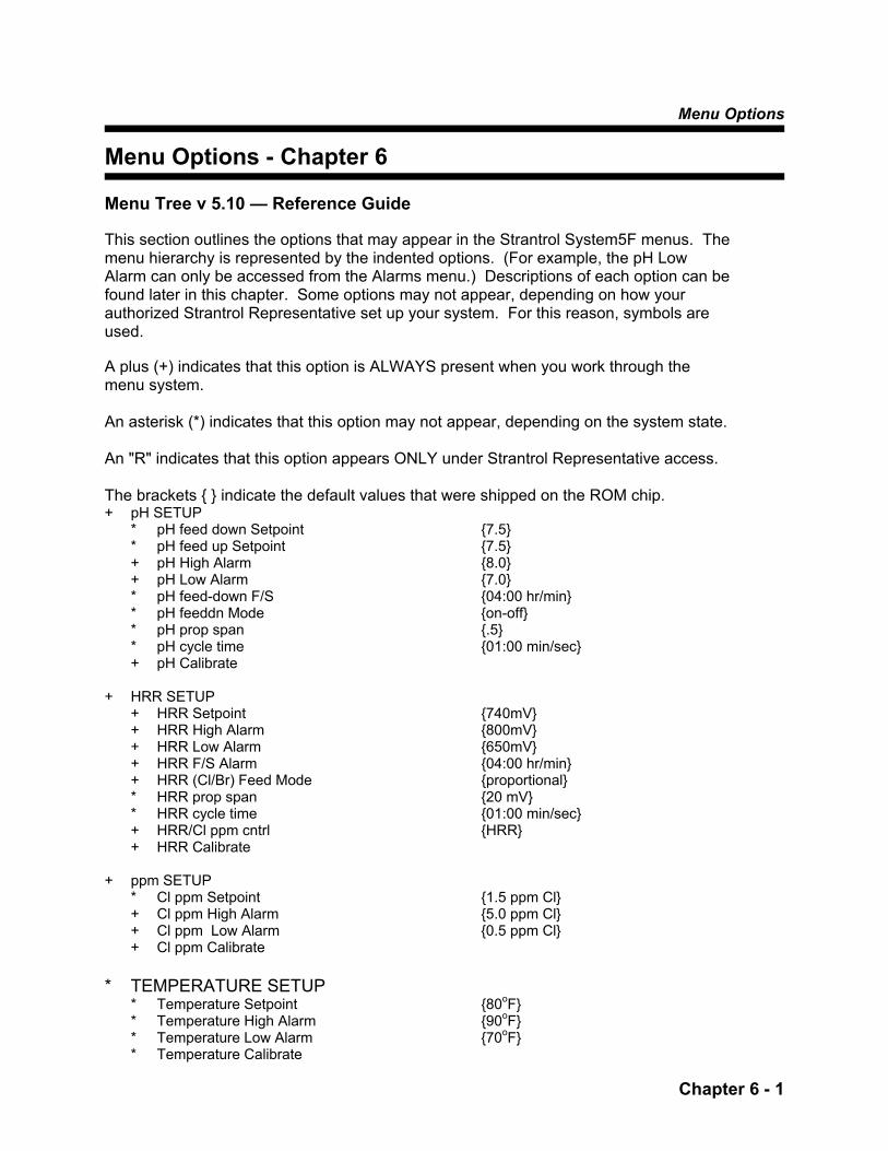
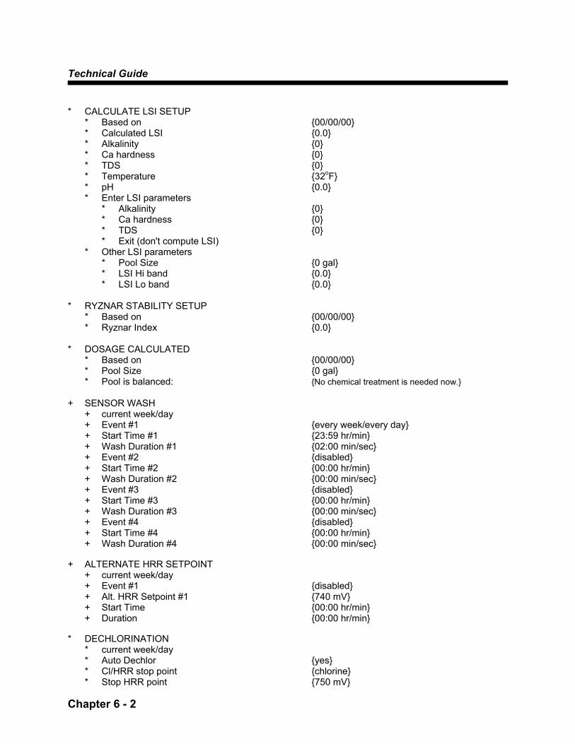
Menu Options - Chapter 6 Menu Tree v 5.10 — Reference Guide This section outlines the options that may appear in the Strantrol System5F menus. The menu hierarchy is represented by the indented options. (For example, the pH Low Alarm can only be accessed from the Alarms menu.) Descriptions of each option can be found later in this chapter. Some options may not appear, depending on how your authorized Strantrol Representative set up your system. For this reason, symbols are used. A plus (+) indicates that this option is ALWAYS present when you work through the menu system. An asterisk (*) indicates that this option may not appear, depending on the system state. An "R" indicates that this option appears ONLY under Strantrol Representative access. The brackets { } indicate the default values that were shipped on the ROM chip. + pH SETUP * pH feed down Setpoint {7.5} * pH feed up Setpoint {7.5} + pH High Alarm {8.0} + pH Low Alarm {7.0} * pH feed-down F/S {04:00 hr/min} * pH feeddn Mode {on-off} * pH prop span {.5} * pH cycle time {01:00 min/sec} + pH Calibrate + HRR SETUP + HRR Setpoint {740mV} + HRR High Alarm {800mV} + HRR Low Alarm {650mV} + HRR F/S Alarm {04:00 hr/min} + HRR (Cl/Br) Feed Mode {proportional} * HRR prop span {20 mV} * HRR cycle time {01:00 min/sec} + HRR/Cl ppm cntrl {HRR} + HRR Calibrate + ppm SETUP * Cl ppm Setpoint {1.5 ppm Cl} + Cl ppm High Alarm {5.0 ppm Cl} + Cl ppm Low Alarm {0.5 ppm Cl} + Cl ppm Calibrate * TEMPERATURE SETUP * Temperature Setpoint {80oF} * Temperature High Alarm {90oF} * Temperature Low Alarm {70oF} * Temperature Calibrate
Technical Guide
Chapter 6 - 2
* CALCULATE LSI SETUP * Based on {00/00/00} * Calculated LSI {0.0} * Alkalinity {0} * Ca hardness {0} * TDS {0} * Temperature {32oF} * pH {0.0} * Enter LSI parameters * Alkalinity {0} * Ca hardness {0} * TDS {0} * Exit (don't compute LSI) * Other LSI parameters * Pool Size {0 gal} * LSI Hi band {0.0} * LSI Lo band {0.0} * RYZNAR STABILITY SETUP * Based on {00/00/00} * Ryznar Index {0.0} * DOSAGE CALCULATED * Based on {00/00/00} * Pool Size {0 gal} * Pool is balanced: {No chemical treatment is needed now.} + SENSOR WASH + current week/day + Event #1 {every week/every day} + Start Time #1 {23:59 hr/min} + Wash Duration #1 {02:00 min/sec} + Event #2 {disabled} + Start Time #2 {00:00 hr/min} + Wash Duration #2 {00:00 min/sec} + Event #3 {disabled} + Start Time #3 {00:00 hr/min} + Wash Duration #3 {00:00 min/sec} + Event #4 {disabled} + Start Time #4 {00:00 hr/min} + Wash Duration #4 {00:00 min/sec} + ALTERNATE HRR SETPOINT + current week/day + Event #1 {disabled} + Alt. HRR Setpoint #1 {740 mV} + Start Time {00:00 hr/min} + Duration {00:00 hr/min} * DECHLORINATION * current week/day * Auto Dechlor {yes} * Cl/HRR stop point {chlorine} * Stop HRR point {750 mV}
Menu Options
Chapter 6 - 3
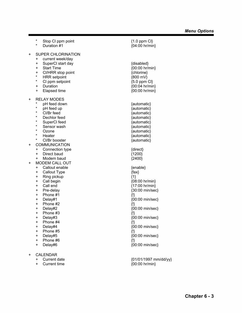
* Stop Cl ppm point {1.0 ppm Cl} * Duration #1 {04:00 hr/min} + SUPER CHLORINATION + current week/day + SuperCl start day {disabled} + Start Time {00:00 hr/min} + Cl/HRR stop point {chlorine} * HRR setpoint {800 mV} * Cl ppm setpoint {5.0 ppm Cl} + Duration {00:04 hr/min} + Elapsed time {00:00 hr/min} + RELAY MODES * pH feed down {automatic} * pH feed up {automatic} * Cl/Br feed {automatic} * Dechlor feed {automatic} * SuperCl feed {automatic} * Sensor wash {automatic} * Ozone {automatic} * Heater {automatic} * Cl/Br booster {automatic} + COMMUNICATION + Connection type {direct} + Direct baud {1200} + Modem baud {2400} + MODEM CALL OUT + Callout enable {enable} + Callout Type {fax} + Ring pickup {1} + Call begin {08:00 hr/min} + Call end {17:00 hr/min} + Pre-delay {30:00 min/sec} + Phone #1 {!} + Delay#1 {00:00 min/sec} + Phone #2 {!} + Delay#2 {00:00 min/sec} + Phone #3 {!} + Delay#3 {00:00 min/sec} + Phone #4 {!} + Delay#4 {00:00 min/sec} + Phone #5 {!} + Delay#5 {00:00 min/sec} + Phone #6 {!} + Delay#6 {00:00 min/sec} + CALENDAR + Current date {01/01/1997 mm/dd/yy} + Current time {00:00 hr/min}
Technical Guide
Chapter 6 - 4
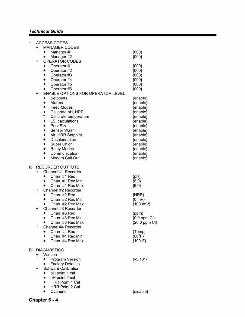
+ ACCESS CODES + MANAGER CODES + Manager #1 {000} + Manager #2 {000} + OPERATOR CODES + Operator #1 {000} + Operator #2 {000} + Operator #3 {000} + Operator #4 {000} + Operator #5 {000} + Operator #6 {000} + ENABLE OPTIONS FOR OPERATOR LEVEL + Setpoints {enable} + Alarms {enable} + Feed Modes {enable} + Calibrate pH, HRR {enable} * Calibrate temperature {enable} + LSI calculations {enable} + Pool Size {enable} + Sensor Wash {enable} + Alt. HRR Setpoint. {enable} + Dechlorination {enable} + Super Chlor {enable} + Relay Modes {enable} + Communication {enable} + Modem Call Out {enable} R+ RECORDER OUTPUTS + Channel #1 Recorder + Chan #1 Rec {pH} + Chan #1 Rec Min {6.0} + Chan #1 Rec Max {9.0} + Channel #2 Recorder + Chan #2 Rec {HRR} + Chan #2 Rec Min {0 mV} + Chan #2 Rec Max {1000mV} + Channel #3 Recorder + Chan #3 Rec {ppm} + Chan #3 Rec Min {0.0 ppm Cl} + Chan #3 Rec Max {20.0 ppm Cl} + Channel #4 Recorder + Chan #4 Rec {Temp} + Chan #4 Rec Min {60oF} + Chan #4 Rec Max {100oF} R+ DIAGNOSTICS + Version + Program Version {v5.10*} + Factory Defaults + Software Calibration + pH point 1 cal + pH point 2 cal + HRR Point 1 Cal + HRR Point 2 Cal + Cyanuric {disable}

Menu Options
Chapter 6 - 5
+ Alt ppm Lookup {disable} * pH for ppm lookup {7.5} + Lookup offset {250} + Temp point1 cal + Temp point2 cal + Temperature units {oF} + Units (US/ metric) {U.S.} + Hardware Calibration + Temperature {disable} + Connection Type {direct} + Direct Baud {1200} + Modem Baud {2400} R+ WARNING BANDS + pH hi band {0.0} + pH hi warn time {00:05 hr/min} + pH lo band {0.0} + pH lo warn time {00:05 hr/min} + HRR hi band {0 mV} + HRR hi warn time {00:05 hr/min} + HRR lo band {0 mV} + HRR lo warn time {00:05 hr/min} + Cl ppm hi band {0.0 ppm Cl} + Cl ppm hi warn tm {00:05 hr/min} + Cl ppm lo band {0.0 ppm Cl} + Cl ppm lo warn tm {00:05 hr/min} R+ DATA LOGGING + High frequency {Every 6 minutes} + Low frequency {Every 2 hours} + Print time intrvl {01:00 hr/min} R+ REP. STARTUP + Current date {01/01/1997 mm/dd/yy} + Current time {00:00 hr/min} + System ID {0} + customer name {!} + system location {!} + rep phone num {!} + Startup date {00/00/00} + Rep code {000} + Relay #1 {pH feed-down} + Relay #2 {sensor wash} + Relay #3 {Cl/Br} + Relay #4 {alarm} * pH feeddn Point {7.5} * pH feedup Point {7.5} + pH High Alarm {8.0} + pH Low Alarm {7.0} * pH feeddn Mode {on-off} * pH feedup Mode {on-off} + HRR/Cl ppm control {HRR} * HRR Setpoint {740 mV} + HRR High Alarm {800 mV} + HRR Low alarm {650 mV}
Technical Guide
Chapter 6 - 6
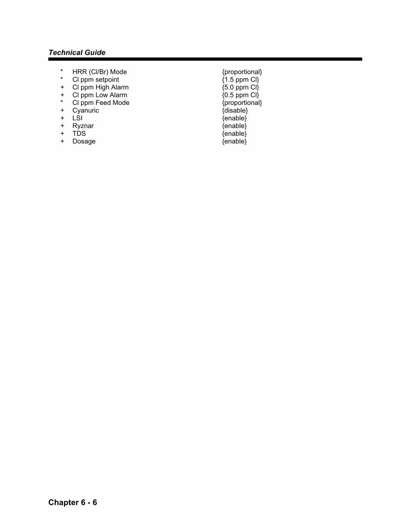
* HRR (Cl/Br) Mode {proportional} * Cl ppm setpoint {1.5 ppm Cl} + Cl ppm High Alarm {5.0 ppm Cl} + Cl ppm Low Alarm {0.5 ppm Cl} * Cl ppm Feed Mode {proportional} + Cyanuric {disable} + LSI {enable} + Ryznar {enable} + TDS {enable} + Dosage {enable}
Menu Options
Chapter 6 - 7
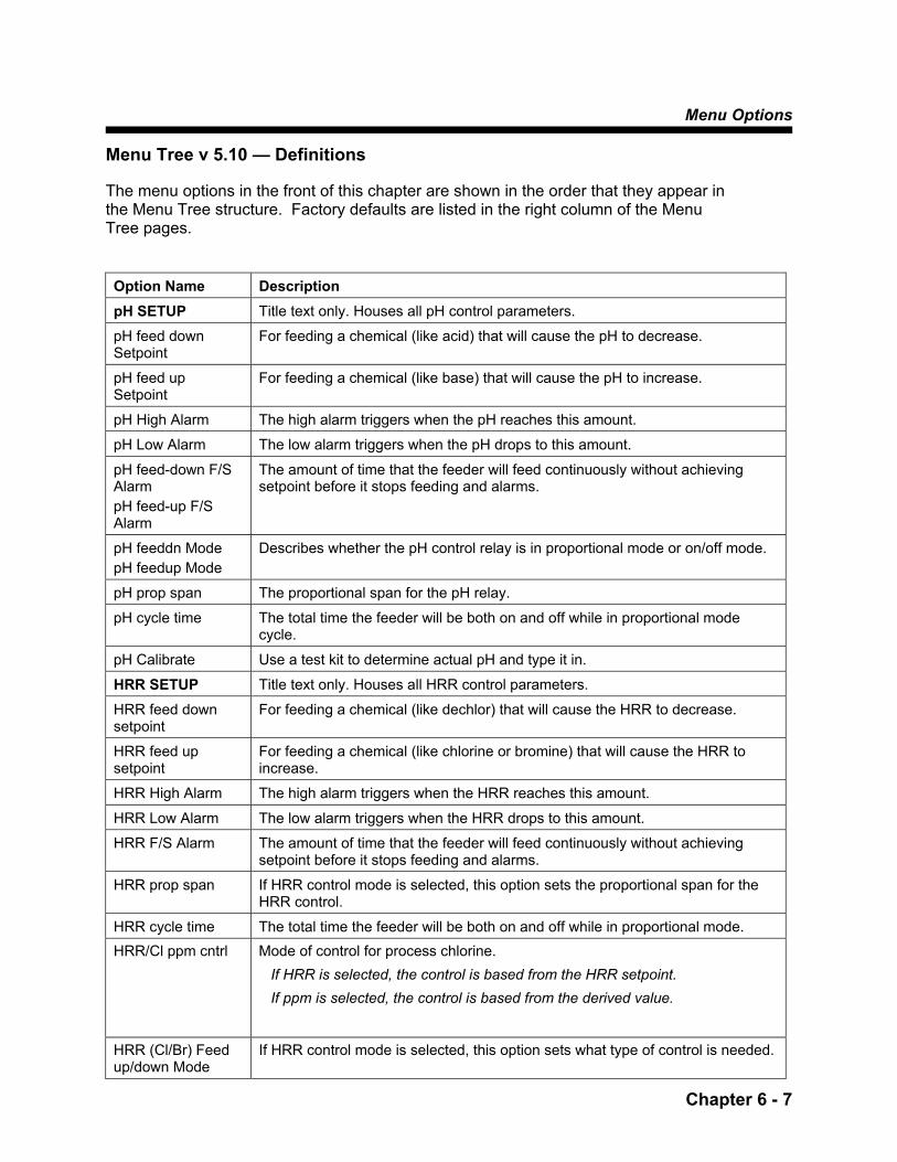
Menu Tree v 5.10 — Definitions The menu options in the front of this chapter are shown in the order that they appear in the Menu Tree structure. Factory defaults are listed in the right column of the Menu Tree pages. Option Name Description pH SETUP Title text only. Houses all pH control parameters.
pH feed down Setpoint
For feeding a chemical (like acid) that will cause the pH to decrease.
pH feed up Setpoint
For feeding a chemical (like base) that will cause the pH to increase.
pH High Alarm The high alarm triggers when the pH reaches this amount.
pH Low Alarm The low alarm triggers when the pH drops to this amount.
pH feed-down F/S Alarm pH feed-up F/S Alarm
The amount of time that the feeder will feed continuously without achieving setpoint before it stops feeding and alarms.
pH feeddn Mode pH feedup Mode
Describes whether the pH control relay is in proportional mode or on/off mode.
pH prop span The proportional span for the pH relay.
pH cycle time The total time the feeder will be both on and off while in proportional mode cycle.
pH Calibrate Use a test kit to determine actual pH and type it in.
HRR SETUP Title text only. Houses all HRR control parameters.
HRR feed down setpoint
For feeding a chemical (like dechlor) that will cause the HRR to decrease.
HRR feed up setpoint
For feeding a chemical (like chlorine or bromine) that will cause the HRR to increase.
HRR High Alarm The high alarm triggers when the HRR reaches this amount.
HRR Low Alarm The low alarm triggers when the HRR drops to this amount.
HRR F/S Alarm The amount of time that the feeder will feed continuously without achieving setpoint before it stops feeding and alarms.
HRR prop span If HRR control mode is selected, this option sets the proportional span for the HRR control.
HRR cycle time The total time the feeder will be both on and off while in proportional mode. HRR/Cl ppm cntrl Mode of control for process chlorine.
If HRR is selected, the control is based from the HRR setpoint. If ppm is selected, the control is based from the derived value.
HRR (Cl/Br) Feed up/down Mode
If HRR control mode is selected, this option sets what type of control is needed.

Technical Guide
Chapter 6 - 8
HRR Calibrate Allows Representative to align HRR on controller to HRR on mV generator.
ppm SETUP Title text only. Houses all Cl ppm control parameters.
Cl ppm High Alarm Alarm that warns user when Cl ppm is too high.
Cl ppm Low Alarm Alarm that warns user when Cl ppm is too low.
Cl ppm Calibrate Allows user to align Cl ppm readout to water test.
TEMPERATURE SETUP
Title text only. Houses all Temperature control parameters. Temperature must be enabled.
Temperature Setpoint
Desired temperature of water. Relay must be assigned to heater.
Temperature High Alarm
Alarm that warns user when Temperature is too high.
Temperature Low Alarm
Alarm that warns user when Temperature is too low.
Temperature Calibrate
Allows user to align Temperature readout to actual water temperature.
CALCULATE LSI SETUP
Title text only. Houses all LSI parameters to be entered by user.
Based on Date that the LSI was last calculated.
Calculated LSI LSI from the last calculation.
Alkalinity Alkalinity of the last LSI calculation.
Ca Hardness Ca Hardness of the last LSI calculation.
TDS TDS of the last LSI calculation. TDS is normally done by a lab.
Temperature Temperature of the last LSI calculation from probe.
pH pH of the last LSI calculation from probe.
Enter LSI Parameters
Title text only. Parameters to be entered to calculate LSI.
Alkalinity Entered after a test kit reading.
Ca Hardness Entered after a test kit reading.
TDS From test kit or enter zero.
Sensor wash Title text only. This is only present when one of the relays has been assigned to sensor wash.
Current week/day This is a read only value of the current week and day.
Event #1 You may choose the first sensor wash to be in the first, second, third or fourth weeks of operation (sensor wash operates on a four-week calendar). You may choose it occur in even or odd weeks, every week or disable it completely. Enter in day - Mon., Tues., Wed., Thurs., Fri., Sat., Sun. or All days. NOTE: Each event for the sensor wash (-2, -3, -4) has the identical description as -1 above.

Menu Options
Chapter 6 - 9
Start Time #1 Enter the time you would like the first sensor wash to begin using military time
(24-hour clock). NOTE: Each start time for the sensor wash (-2, -3, -4) has the identical description as -1 above.
Wash Duration#1 Enter the duration of the first sensor wash from 0 to 2 minutes. NOTE: Each wash duration for the sensor wash (-2, -3, -4) has the identical description as -1 above.
Alternate HRR Setpoint
Title text only. Houses all parameters for the alternate HRR setpoint function.
Current week/day This is a read only value of the current week and day.
Event #1 You may choose the alternate HRR setpoint to be in the first, second, third or fourth weeks of operation. You may choose it occur in even or odd weeks, every week or disable it completely. Enter in day - Mon., Tues., Wed., Thurs., Fri., Sat., Sun. or All days. NOTE: Each event for the alternate HRR setpoint (-2, -3, and -4) has the identical description as -1 above.
Alt. HRR Setpoint This is the alternate setpoint.
Start Time Enter the time you would like the Alternate setpoint to begin using military time (24-hour clock).
Duration Enter how long you would like the Alternate Setpoint to be in effect (number of hours and minutes).
Dechlorination Title text only. Houses all parameters for the Dechlorination function. This is only present when one of the relays has been assigned to dechorination.
Current week/day This is a read only value of the current week and day.
Auto Dechlor Yes if you want dechorination to automatically begin after the superchlorination process and No if, you don't..
Cl/HRR stop point The Chlorine or HRR point at which the process will stop.
Duration How long you want the process to last in hours and minutes. This functions as a failsafe timer, stopping the process after a certain time even if the stop setpoint has not yet been reached.
Superchlorination Title text only. Houses all parameters for the Superchlorination function. This is only present when one of the relays has been assigned to superchlorination.
Current week/day This is a read only value of the current week and day.
SuperCl start day You may choose the first super chlorination to be the first, second, third or fourth weeks of operation. You may choose to have it occur in only even or odd weeks, every week or disable it completely. Enter in day - Mon., Tues., Wed., Thurs., Fri., Sat., Sun. or All days.
Start Time #1 Enter the time you would like the super chlorination to begin using military time.
Cl/HRR stop point Do you want to use chlorine or HRR setpoint to stop the process.
Duration How long you want the process to last in hours and minutes. This functions as a failsafe timer, stopping the process after a certain time even if the stop setpoint has not yet been reached.
Elapsed Time The time since the process began.
Technical Guide
Chapter 6 - 10
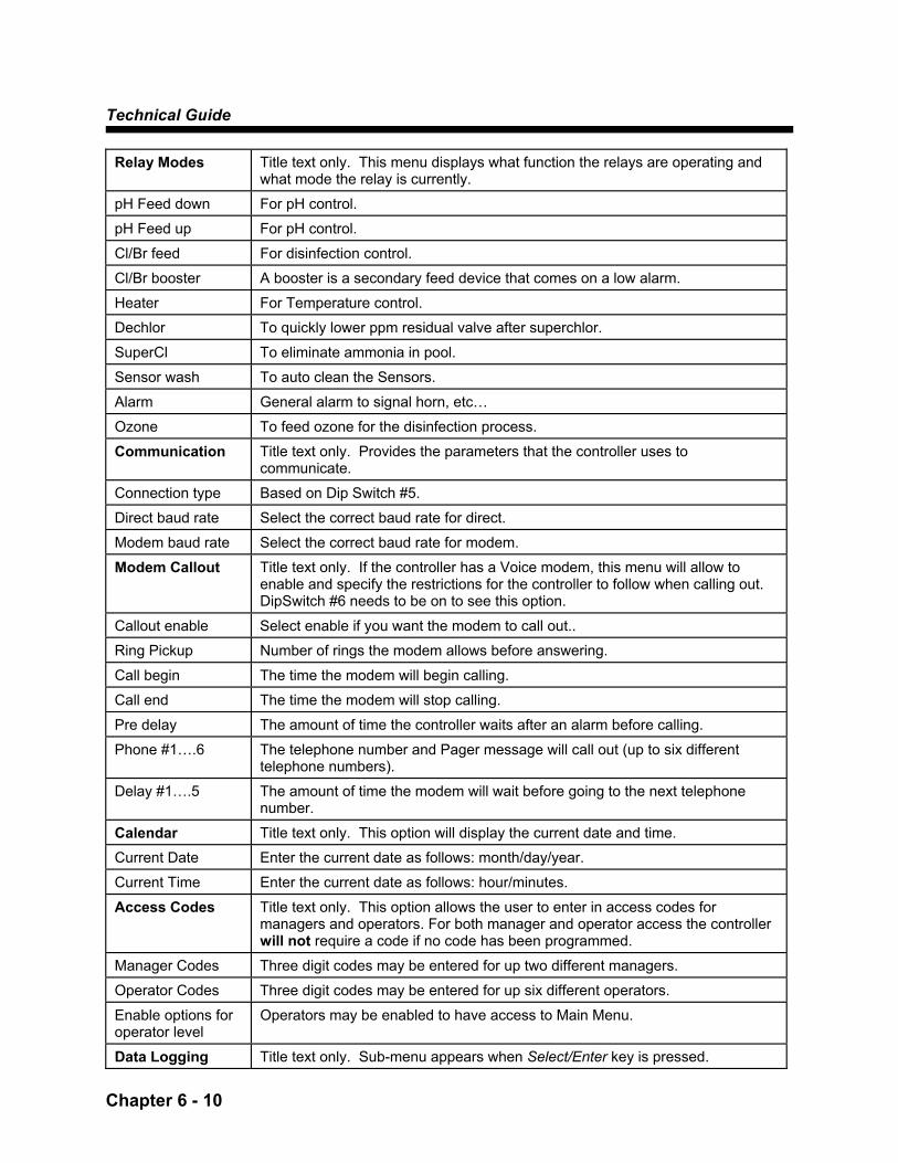
Relay Modes Title text only. This menu displays what function the relays are operating and what mode the relay is currently.
pH Feed down For pH control.
pH Feed up For pH control.
Cl/Br feed For disinfection control.
Cl/Br booster A booster is a secondary feed device that comes on a low alarm.
Heater For Temperature control.
Dechlor To quickly lower ppm residual valve after superchlor.
SuperCl To eliminate ammonia in pool.
Sensor wash To auto clean the Sensors.
Alarm General alarm to signal horn, etc…
Ozone To feed ozone for the disinfection process.
Communication Title text only. Provides the parameters that the controller uses to communicate.
Connection type Based on Dip Switch #5.
Direct baud rate Select the correct baud rate for direct.
Modem baud rate Select the correct baud rate for modem.
Modem Callout Title text only. If the controller has a Voice modem, this menu will allow to enable and specify the restrictions for the controller to follow when calling out. DipSwitch #6 needs to be on to see this option.
Callout enable Select enable if you want the modem to call out..
Ring Pickup Number of rings the modem allows before answering.
Call begin The time the modem will begin calling.
Call end The time the modem will stop calling.
Pre delay The amount of time the controller waits after an alarm before calling.
Phone #1….6 The telephone number and Pager message will call out (up to six different telephone numbers).
Delay #1….5 The amount of time the modem will wait before going to the next telephone number.
Calendar Title text only. This option will display the current date and time.
Current Date Enter the current date as follows: month/day/year.
Current Time Enter the current date as follows: hour/minutes.
Access Codes Title text only. This option allows the user to enter in access codes for managers and operators. For both manager and operator access the controller will not require a code if no code has been programmed.
Manager Codes Three digit codes may be entered for up two different managers.
Operator Codes Three digit codes may be entered for up six different operators.
Enable options for operator level
Operators may be enabled to have access to Main Menu.
Data Logging Title text only. Sub-menu appears when Select/Enter key is pressed.
Menu Options
Chapter 6 - 11
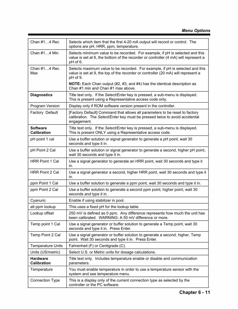
Chan #1…4 Rec Selects which item that the first 4-20 mA output will record or control. The options are pH, HRR, ppm, temperature.
Chan #1…4 Min Selects minimum value to be recorded. For example, if pH is selected and this value is set at 6, the bottom of the recorder or controller (4 mA) will represent a pH of 6.
Chan #1…4 Rec Max
Selects maximum value to be recorded. For example, if pH is selected and this value is set at 9, the top of the recorder or controller (20 mA) will represent a pH of 9. NOTE: Each Chan output (#2, #3, and #4) has the identical description as Chan #1 min and Chan #1 max above.
Diagnostics Title text only. If the Select/Enter key is pressed, a sub-menu is displayed. This is present using a Representative access code only.
Program Version Display only if ROM software version present in the controller.
Factory Default [Factory Default] Command that allows all parameters to be reset to factory calibration. The Select/Enter key must be pressed twice to avoid accidental engagement.
Software Calibration
Title text only. If the Select/Enter key is pressed, a sub-menu is displayed. This is present ONLY using a Representative access code.
pH point 1 cal Use a buffer solution or signal generator to generate a pH point, wait 30 seconds and type it in.
pH Point 2 Cal Use a buffer solution or signal generator to generate a second, higher pH point, wait 30 seconds and type it in.
HRR Point 1 Cal Use a signal generator to generate an HRR point, wait 30 seconds and type it in.
HRR Point 2 Cal Use a signal generator a second, higher HRR point, wait 30 seconds and type it in.
ppm Point 1 Cal Use a buffer solution to generate a ppm point, wait 30 seconds and type it in. ppm Point 2 Cal Use a buffer solution to generate a second ppm point, higher point, wait 30
seconds and type it in. Cyanuric Enable if using stabilizer in pool. alt ppm lookup This uses a fixed pH for the lookup table. Lookup offset 250 mV is defined as 0 ppm. Any difference represents how much the unit has
been calibrated. WARNING: A 50 mV difference or more. Temp point 1 Cal Use a signal generator or buffer solution to generate a Temp point, wait 30
seconds and type it in. Press Enter. Temp Point 2 Cal Use a signal generator or buffer solution to generate a second, higher, Temp
point. Wait 30 seconds and type it in. Press Enter. Temperature Units Fahrenheit (F) or Centigrade (C). Units (US/metric) Select U.S. or Metric units for dosage calculations. Hardware Calibration
Title text only. Includes temperature enable or disable and communication parameters.
Temperature You must enable temperature in order to use a temperature sensor with the system and see temperature menu.
Connection Type This is a display only of the current connection type as selected by the controller or the PC software.

Technical Guide
Chapter 6 - 12
Direct baud The com port on your PC talks to the controller com port at this baud rate. The max setting is 19200.
Modem Baud The modem talks to the PC at this baud rate. Currently, the Data Modem is 33,600 baud; the Data/Voice modem is 2400 baud.
Warning Bands Title text only. Warning bands provide a series of gradual alarms over a time period. They alert the user before water gets too far out of control.
pH hi band High end pH alarm that will trigger before the actual alarm. pH hi warn time The time the warning band will sound and wait before triggering the actual
alarm. pH lo band Low end pH alarm that will trigger before the actual alarm. pH hi warn time The time the warning band will sound and wait before triggering the actual
alarm. HRR hi band High end HRR alarm that will trigger before the actual alarm. HRR hi warn time The time the warning band will sound and wait before triggering the actual
alarm. HRR lo band Low end HRR alarm that will trigger before the actual alarm. HRR lo warn time The time the warning band will sound and wait before triggering the actual
alarm. Cl ppm hi band High end Cl ppm alarm that will trigger before the actual alarm.
Cl ppm hi warn time
The time the warning band will sound and wait before triggering the actual alarm.
Cl ppm lo band Low end Cl ppm alarm that will trigger before the actual alarm.
Cl ppm hi warn time
The time the warning band will sound and wait before triggering the actual alarm.
Datalogging Title text only. Specifications for the controller to follow while datalogging information.
High Frequency Information will be recorded in 1 - 6 minute intervals.
Low Frequency Information will be recorded in 1 - 4 hour intervals.
Print time Interval Specify when the controller is to print out the water parameters.
Rep Start Up Title text only. Quick controller setup menu.
Current Date Current date shown as mm/dd/yy
Current Time Current time shown as 0-24:00
System ID Type in the serial number of the unit here.
Customer Name The name entered here will show on the facepanel
System Location Location entered here will show on the facepanel.
Rep Phone Num. Number entered here will show on the facepanel.
Startup Date This is the date the unit was put into use.
Rep. Code This is the access code of the Rep.
Relay #1 . . . 4 Relays may be configured as pH Feed down, pH Feed up, Cl/Br Feed Cl/Br booster, heater, Dechlor feed, SuperCl feed, Sensor Wash, Alarm and Ozone.
pH High Alarm The pH High Alarm point.
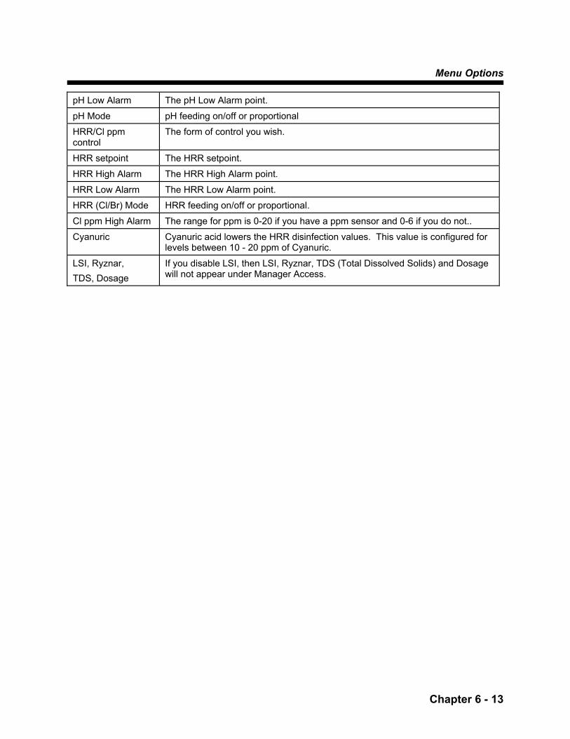
Menu Options
Chapter 6 - 13
pH Low Alarm The pH Low Alarm point.
pH Mode pH feeding on/off or proportional
HRR/Cl ppm control
The form of control you wish.
HRR setpoint The HRR setpoint.
HRR High Alarm The HRR High Alarm point.
HRR Low Alarm The HRR Low Alarm point.
HRR (Cl/Br) Mode HRR feeding on/off or proportional.
Cl ppm High Alarm The range for ppm is 0-20 if you have a ppm sensor and 0-6 if you do not..
Cyanuric Cyanuric acid lowers the HRR disinfection values. This value is configured for levels between 10 - 20 ppm of Cyanuric.
LSI, Ryznar, TDS, Dosage
If you disable LSI, then LSI, Ryznar, TDS (Total Dissolved Solids) and Dosage will not appear under Manager Access.


Sensor Wash
Chapter 7 - 1
SENSOR WASH OPTION - Chapter 7 Sensor Wash
If the optional sensor wash is used, install the plumbing and configure the system for Sensor Wash use. NOTE: For most applications, the default settings need not be changed.
Configure Sensor Wash
1. Choose one of the unused relays and assign it to sensor wash. Select Menu: [rep startup], the default sensor wash relay is #2.
2. Connect the feed device to the appropriate relay output.
3. Enter [Sensor Wash] sub-menu to modify the sensor
wash settings.
Technical Guide
Chapter 7 - 2
Programming Sensor Wash
After the sensor wash option is enabled, steps must be taken to program the automatic sensor wash. The System5F automatic sensor wash program is based on:
A four-week cycle that does not correspond to the
day and week of the calendar.
· The cycle begins with Sunday, week 1, and ends with Saturday, week 4.
A 24-hour clock
· Add 12 hours to calculate afternoon and
evening times.
Sensor Wash should be done on a daily basis. Time should be set for All week/Every day.
· The operator should select time of day.
Four programmable times that allows you to select
4 days out of selected weeks to run feed device. NOTE: There is only one “on-line” duration setting.
Start times are based on two components:
· week and day
· hour and minutes

Sensor Wash
Chapter 7 - 3
Menu Displays
An explanation of the controller displays is presented in the following table.
Controller Choices Characters Shown on Display
Description
Days of the week
1st week
week 1
2nd week
week 2
3rd week
week 3
4th week
week 4
Odd week
odd number week
Even week
even number week
Every week
All weeks
disabled
No sensor wash
Monday Tuesday Wednesday Thursday Friday Saturday Sunday Everyday
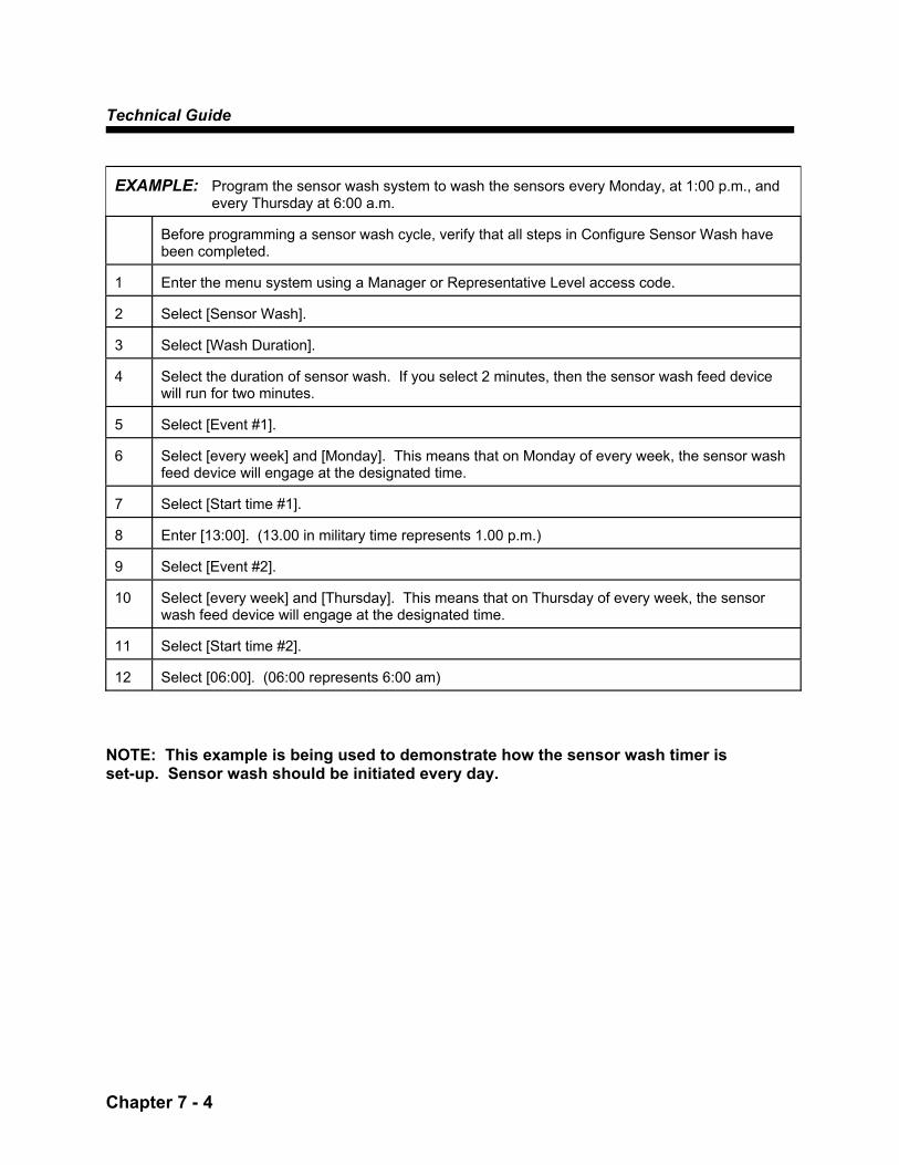
Technical Guide
Chapter 7 - 4
EXAMPLE: Program the sensor wash system to wash the sensors every Monday, at 1:00 p.m., and
every Thursday at 6:00 a.m.
Before programming a sensor wash cycle, verify that all steps in Configure Sensor Wash have been completed.
1
Enter the menu system using a Manager or Representative Level access code.
2
Select [Sensor Wash].
3
Select [Wash Duration].
4
Select the duration of sensor wash. If you select 2 minutes, then the sensor wash feed device will run for two minutes.
5
Select [Event #1].
6
Select [every week] and [Monday]. This means that on Monday of every week, the sensor wash feed device will engage at the designated time.
7
Select [Start time #1].
8
Enter [13:00]. (13.00 in military time represents 1.00 p.m.)
9
Select [Event #2].
10
Select [every week] and [Thursday]. This means that on Thursday of every week, the sensor wash feed device will engage at the designated time.
11
Select [Start time #2].
12
Select [06:00]. (06:00 represents 6:00 am)
NOTE: This example is being used to demonstrate how the sensor wash timer is set-up. Sensor wash should be initiated every day.

Superchlorination
Chapter 8 - 1
Superchlorination - Chapter 8 Superchlorination Programming
The System5F superchlorination program features a single programmable time used to start the superchlorination procedure. To obtain superchlorination one of the four relays must be assigned to superchlorination. This start time is based on:
A four-week cycle that does NOT correspond to the
day and week of the calendar. A 24-hour clock. Two components
· week and day
· hour and minutes
An example programming situation is outlined later in this section.
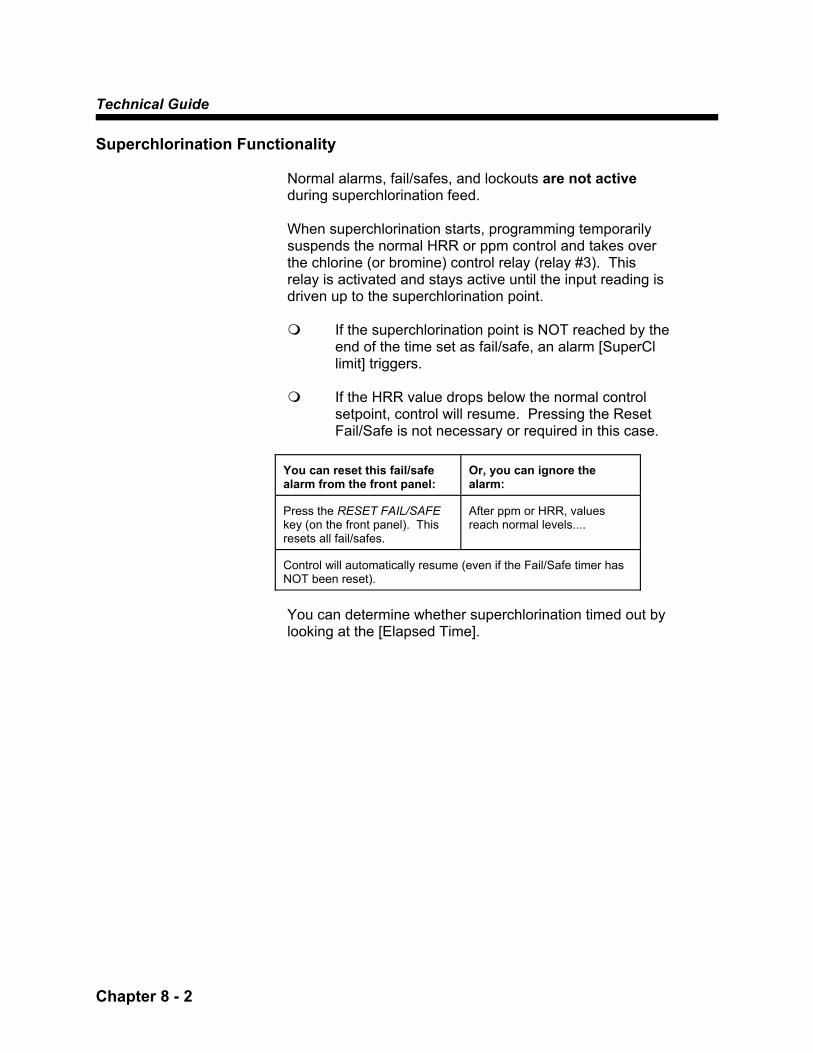
Technical Guide
Chapter 8 - 2
Superchlorination Functionality
Normal alarms, fail/safes, and lockouts are not active during superchlorination feed. When superchlorination starts, programming temporarily suspends the normal HRR or ppm control and takes over the chlorine (or bromine) control relay (relay #3). This relay is activated and stays active until the input reading is driven up to the superchlorination point.
If the superchlorination point is NOT reached by the
end of the time set as fail/safe, an alarm [SuperCl limit] triggers.
If the HRR value drops below the normal control
setpoint, control will resume. Pressing the Reset Fail/Safe is not necessary or required in this case.
You can reset this fail/safe alarm from the front panel:
Or, you can ignore the alarm:
Press the RESET FAIL/SAFE key (on the front panel). This resets all fail/safes.
After ppm or HRR, values reach normal levels....
Control will automatically resume (even if the Fail/Safe timer has NOT been reset).
You can determine whether superchlorination timed out by looking at the [Elapsed Time].

Superchlorination
Chapter 8 - 3
EXAMPLE: Program a superchlorination for Tuesday at 2:00 p.m. every fourth week. 1
Enter the menu system using a Manager or Representative access code.
2
Select [superchlorination]. The current week and day of the cycle is displayed. The day of the cycle should correspond to the current day of the week. If this is not the case, consult authorized USFilter Stranco Products personnel.
3
Select [SuperCl start day].
4
Select [4th week] and [Tuesday]. This means that on Tuesday of every 4th week, the superchlorination feed device will engage at the designated time.
5
Select [Start Time]. Enter [14:00]. (14:00 in military time represents 2:00 p.m.)
6
Select [Cl/HRR stop point]. Select the control of superchlorination. [chlorine] or [HRR]
7
Select [Cl ppm setpoint] or [HRR setpoint] depending on what you selected for the stop point. Enter in value that you wish the controller to superchlorinate.
8
Select [Duration]. Select the duration of superchlorination. If you select 2 hours, then the superchlorination feed device will run for two hours before triggering the F/S alarm.
9
[Elapsed Time] If the controller is in the middle of superchlorination (and the feed device is ON), this value represents how long the feed device has been running. If the feed device is not on, this value is equal to the prior [superchlorination time to complete]. For example, if the superchlorination setpoint is set to 800 mV, and superchlorination is reached in two hours, the value displayed will be 2 hours.


Calculate LSI Setup
Chapter 9 - 1
Calculate LSI Setup - Chapter 9 LSI Programming
LSI The System5F will calculate and display a LSI after the user has entered certain water chemistry values. After the user has entered a value, an asterisk will appear next to the value. The LSI will only be calculated after all values have been entered or updated.
Ryznar Index The System5F will calculate and display a Ryznar Index after the user has entered the values that were previously entered for the LSI. The values only need to be entered once for the calculation of both Ryznar and LSI. NOTE: All the parameters must be re-entered with every new calculation. Even if only one parameter has changed, all must be re-entered.
Dosage Calculated
The System5F will calculate and display the chemicals needed for a balanced pool.

Technical Guide
Chapter 9 - 2
EXAMPLE: Entering values for LSI and Ryznar Index calculations
1
Enter the menu system using a Operator, Manager or Representative access code.
2
Select [Calculate LSI Setup].
3
Select [Enter LSI parameters].
4
Select [Alkalinity] then enter.
Enter test kit reading.
5
Select [Ca hardness] then enter.
Enter test kit reading.
6
Select [TDS] then enter.
Most pools are from 1500 to 2500. This value doesn't have a big affect on calculations, so TDS doesn't have to be accurate.
NOTE: An asterisk must be on the right side of each value for step # 7 to appear.
7 Select [Compute LSI and Exit].
8
Select [Enter other parameters].
9
Select [Pool Size] then enter.
Enter in approximate volume of pool.
10
Select [LSI Hi band] then enter.
Usually .5
11
Select [LSI Lo band] then enter.
Usually 0.
12
Press Previous Screen button until the Main Menu is displayed.
13
Select [Ryznar Stability Setup].
Date of Calculation and Ryznar will be displayed.
14
Press Previous Screen button until the Main Menu is displayed.
15
Select [Dosage Calculated].
Date of Calculation, Pool Size and what chemicals are needed to balance pool plus quantities.
Alternate HRR Setpoint
Chapter 10 - 1
Alternate HRR Setpoint - Chapter 10 Alternate HRR Setpoint Programming
The System5F alternate HRR setpoint program features a single programmable time used to start the alternate HRR setpoint procedure. To obtain alternate HRR setpoint the time must be enabled and the timer set. No relay is assigned. This start time is based on:
A four-week cycle that does NOT correspond to the
day and week of the calendar. A 24-hour clock. Two components
· week and day
· hour and minutes
An example-programming situation is outlined later in this section.

Technical Guide
Chapter 10 - 2
Alternate HRR Setpoint Functionality
Normal alarms, fail/safes, and lockouts are active during an alternate HRR feed. When alternate HRR setpoint starts, programming temporarily suspends the normal HRR or ppm control and takes over the chlorine (or bromine) control relay (relay #3). The Alternate Setpoint is activated and stays active through the duration time desired.
EXAMPLE: Program an alternate HRR setpoint for Tuesday at 8:00 p.m. until 9:00 a.m. every first week. 1
Enter the menu system using an Operator, Manager or Representative access code.
2
Select [Alternate HRR Setpoint]. The current week and day of the cycle is displayed. The day of the cycle should correspond to the current day of the week. If this is not the case, consult authorized USFilter Stranco Products personnel.
3
Select [Event #1].
4
Select [1st week] and [Tuesday]. This means that on Tuesday of every 1st week, the alternate HRR will engage at the designated time.
5
Select [Alt. HRR Setpoint]. Enter Alternate HRR Setpoint.
6
Select [Start Time]. Enter [20:00]. (20:00 in military time represents 8:00 p.m.)
7
Select [Duration]. Enter [13:00]. (13:00 is hours from start time)

Dechlorination Setpoint
Chapter 11 - 1
Dechlorination Setpoint - Chapter 11 Dechlorination Programming
The System5F dechlorination program is activated only after Superchlorination is done. If a relay is assigned and Dechlor is enabled the Auto Dechlor will be activated.

Technical Guide
Chapter 11 - 2
Dechlorination Functionality
Normal alarms, fail/safes, and lockouts are not active during a dechlorination feed. The dechlorination relay is a separate relay and needs to be assigned for activation through Representative Access. When dechlorination starts, programming temporarily suspends the normal HRR or ppm control. This relay is activated only after a Super Cl2 and stays active until the HRR or Cl ppm reaches stop setpoint or until fail/safe time is reached.
EXAMPLE: Program a dechlorination for 2:00 hours after superchlorination. 1
Enter the menu system using an Operator, Manager or Representative access code.
2
Select [Dechlorination]. The current week and day of the cycle is displayed.
3
Select [Cl/HRR stop point]. Dechlorination can be controlled by either Cl or HRR.
4
Select [Stop HRR or Cl point]. Dechlorination will stop and regular control will engage at this point.
5
Select [Duration]. Enter [2:00]. (2:00 means hours from start time)
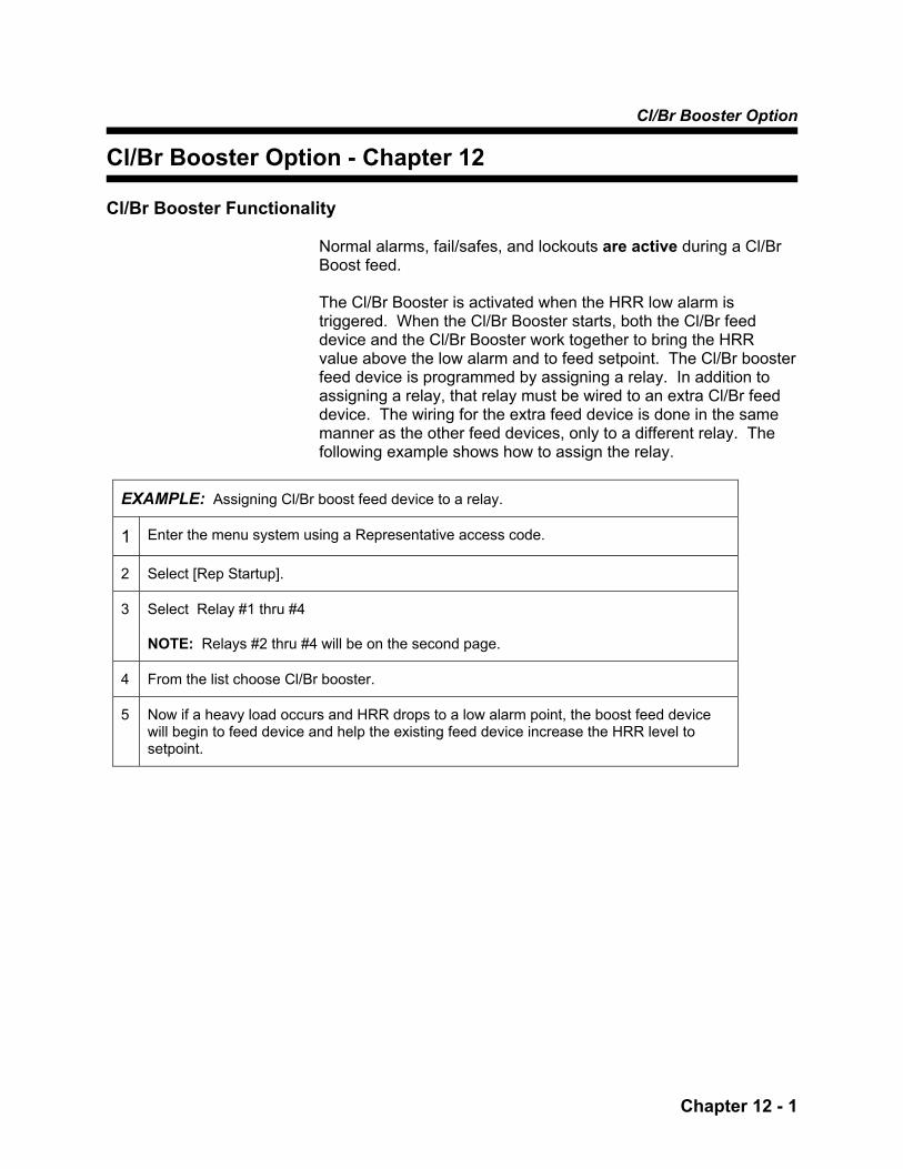
Cl/Br Booster Option
Chapter 12 - 1
Cl/Br Booster Option - Chapter 12 Cl/Br Booster Functionality
Normal alarms, fail/safes, and lockouts are active during a Cl/Br Boost feed. The Cl/Br Booster is activated when the HRR low alarm is triggered. When the Cl/Br Booster starts, both the Cl/Br feed device and the Cl/Br Booster work together to bring the HRR value above the low alarm and to feed setpoint. The Cl/Br booster feed device is programmed by assigning a relay. In addition to assigning a relay, that relay must be wired to an extra Cl/Br feed device. The wiring for the extra feed device is done in the same manner as the other feed devices, only to a different relay. The following example shows how to assign the relay.
EXAMPLE: Assigning Cl/Br boost feed device to a relay.
1 Enter the menu system using a Representative access code.
2 Select [Rep Startup].
3 Select Relay #1 thru #4
NOTE: Relays #2 thru #4 will be on the second page.
4 From the list choose Cl/Br booster.
5 Now if a heavy load occurs and HRR drops to a low alarm point, the boost feed device will begin to feed device and help the existing feed device increase the HRR level to setpoint.

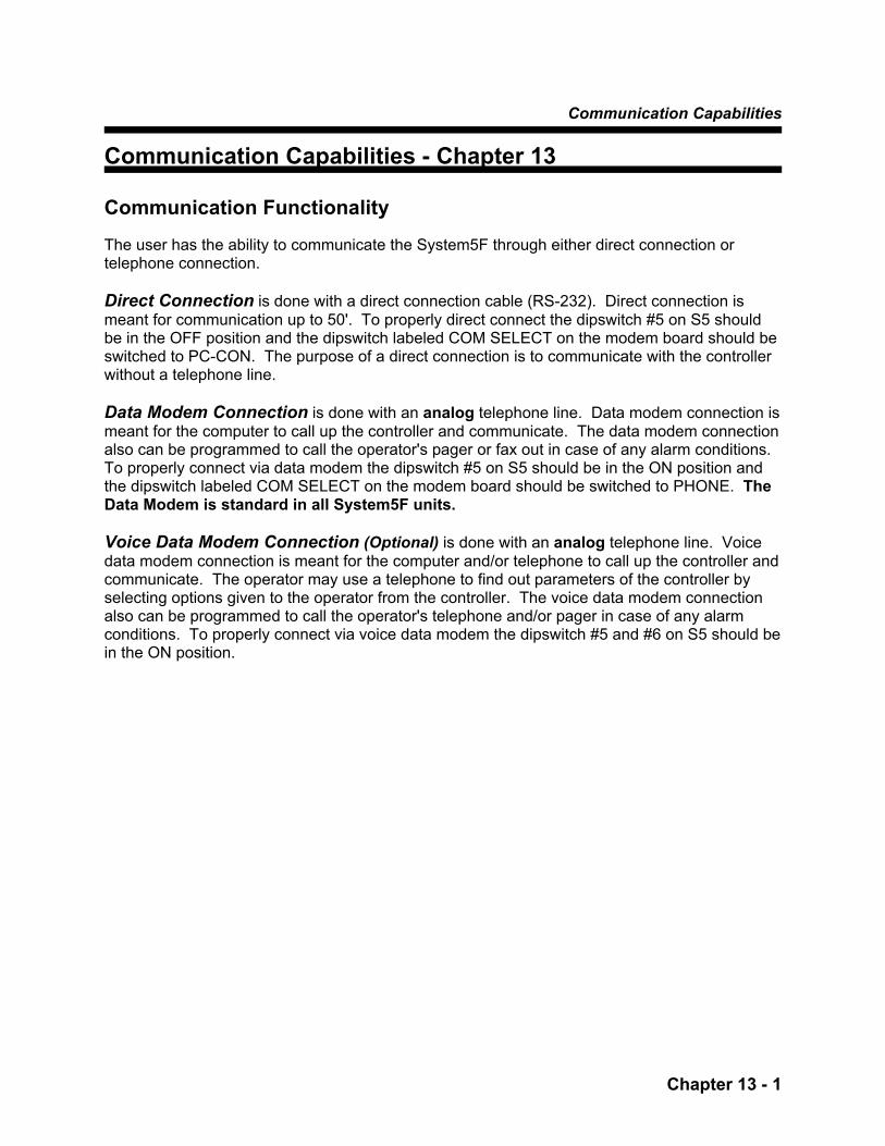
Communication Capabilities
Chapter 13 - 1
Communication Capabilities - Chapter 13 Communication Functionality The user has the ability to communicate the System5F through either direct connection or telephone connection. Direct Connection is done with a direct connection cable (RS-232). Direct connection is meant for communication up to 50'. To properly direct connect the dipswitch #5 on S5 should be in the OFF position and the dipswitch labeled COM SELECT on the modem board should be switched to PC-CON. The purpose of a direct connection is to communicate with the controller without a telephone line. Data Modem Connection is done with an analog telephone line. Data modem connection is meant for the computer to call up the controller and communicate. The data modem connection also can be programmed to call the operator's pager or fax out in case of any alarm conditions. To properly connect via data modem the dipswitch #5 on S5 should be in the ON position and the dipswitch labeled COM SELECT on the modem board should be switched to PHONE. The Data Modem is standard in all System5F units. Voice Data Modem Connection (Optional) is done with an analog telephone line. Voice data modem connection is meant for the computer and/or telephone to call up the controller and communicate. The operator may use a telephone to find out parameters of the controller by selecting options given to the operator from the controller. The voice data modem connection also can be programmed to call the operator's telephone and/or pager in case of any alarm conditions. To properly connect via voice data modem the dipswitch #5 and #6 on S5 should be in the ON position.
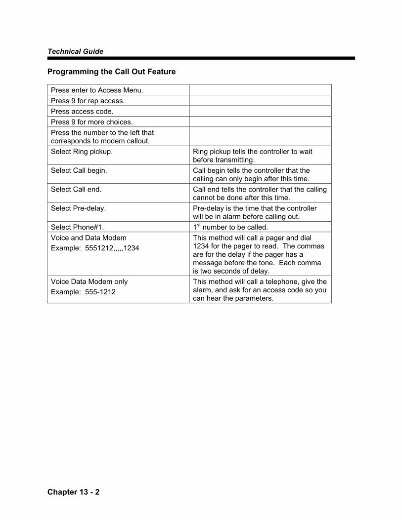
Technical Guide
Chapter 13 - 2
Programming the Call Out Feature Press enter to Access Menu. Press 9 for rep access. Press access code. Press 9 for more choices. Press the number to the left that corresponds to modem callout.
Select Ring pickup. Ring pickup tells the controller to wait before transmitting.
Select Call begin. Call begin tells the controller that the calling can only begin after this time.
Select Call end. Call end tells the controller that the calling cannot be done after this time.
Select Pre-delay. Pre-delay is the time that the controller will be in alarm before calling out.
Select Phone#1. 1st number to be called. Voice and Data Modem Example: 5551212,,,,,1234
This method will call a pager and dial 1234 for the pager to read. The commas are for the delay if the pager has a message before the tone. Each comma is two seconds of delay.
Voice Data Modem only Example: 555-1212
This method will call a telephone, give the alarm, and ask for an access code so you can hear the parameters.
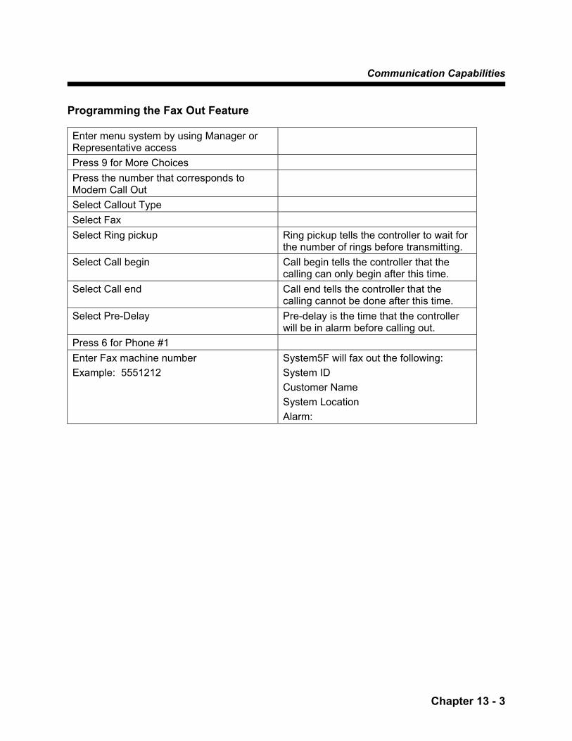
Communication Capabilities
Chapter 13 - 3
Programming the Fax Out Feature Enter menu system by using Manager or Representative access
Press 9 for More Choices Press the number that corresponds to Modem Call Out
Select Callout Type Select Fax Select Ring pickup Ring pickup tells the controller to wait for
the number of rings before transmitting. Select Call begin Call begin tells the controller that the
calling can only begin after this time. Select Call end Call end tells the controller that the
calling cannot be done after this time. Select Pre-Delay Pre-delay is the time that the controller
will be in alarm before calling out. Press 6 for Phone #1 Enter Fax machine number Example: 5551212
System5F will fax out the following: System ID Customer Name System Location Alarm:
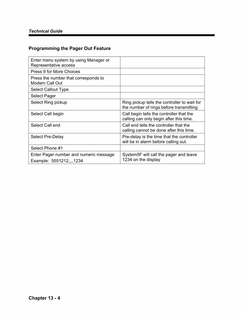
Technical Guide
Chapter 13 - 4
Programming the Pager Out Feature Enter menu system by using Manager or Representative access
Press 9 for More Choices Press the number that corresponds to Modem Call Out
Select Callout Type Select Pager Select Ring pickup Ring pickup tells the controller to wait for
the number of rings before transmitting. Select Call begin Call begin tells the controller that the
calling can only begin after this time. Select Call end Call end tells the controller that the
calling cannot be done after this time. Select Pre-Delay Pre-delay is the time that the controller
will be in alarm before calling out. Select Phone #1 Enter Pager number and numeric message Example: 5551212,,,,1234
System5F will call the pager and leave 1234 on the display
Communication Capabilities
Chapter 13 - 5
Voice Data Modem Terminology & Operations Dial In Your staff can always call up (or dial) the Voice Data Modem via telephone or modem. Call Out You have the choice of setting up the Voice Data Modem to call out pool facility staff members in the event of an alarm. You program the list of staff phone numbers for the Voice Data Modem to call. Staff answering the call will hear a synthesized voice presenting an alarm report. Enabling the call out allows the Voice Data Modem to dial out to facility staff. Disabling the call out means that the Voice Data Modem will not be able to call your staff. Access Code When you call in or when the Voice Data Modem calls out, you will be asked to enter your access code. The Manager Level access code is the same as the one used on the System5F controller keypad, followed by the pound (#) sign. Manager Level access allows users to change Voice Data Modem AND System5F settings. If you wish, staff can also use an access that allows them to only monitor the System5F and listen to reports. Use access code ##. Anyone using ## will NOT be able to modify Voice Data Modem or System5F settings. Overall Delay The overall delay value sets the amount of time that the Voice Data Modem will wait to begin calling down the call out list AFTER an alarm has been activated. Data Mode If you have a PC, you can use Strantrol Virtual Controller (SVC) software to call your Voice Data Modem. This offers an alternative programming method for customizing the Voice Data Modem settings. If you do not have SVC, programming the Voice Data Modem will be done from the System5F facepanel. Decimal Placement for Values Entered Decimal Points are added automatically because the decimal placement logic is built into the Voice Data Modem factory programming. For example, when entering the pH feed point, pressing 75# will be interpreted as 7.5. Carrier The carrier tone is the long beep that you hear before the PC connects to the Voice Data Modem. Enabling the carrier allows users to "call in" using a computer (SVC) or a telephone. Disabling the carrier allows users to "call in" using only the telephone.

Technical Guide
Chapter 13 - 6
SAVE or ENTER All data entered on the telephone touch tone pad must be followed by the # button. For example:
The Voice Data Modem says: You Enter: "Please enter pH feeddown point" 75# "Please enter ring pickup value" 4# "You are about to Enable [option], press # to confirm.
#
"You are about to Disable [option], press # to confirm.
#
When you call the Voice Data Modem, you will be working with a simple menu structure
START
Caller enters his access code
See the ACCESS CODE section.
See the flowchart on the next page for HOME MENU.
HOME MENU
Caller dials the Voice Data Modem
Phone rings at Voice Data Modem
When number of Rings = ring pickup value
Connection is made to the Voice Data Modem
“Welcome to the Strantrol System5F. Please enter
Access Code

Communication Capabilities
Chapter 13 - 7
Press “9” to Terminate Call
Stop
HOME MENU Listen to Menu Choices
Press “0” for Status Report A Voice Data Modem message reports on the System5F status # To repeat the report * To return to Home Menu
Press “3” for Modem Setting 1 Modify Ring Pickup Value 3 Enable/Disable Carrier 5 Enable/Disable Alarm Call Out # To repeat the report * To return to Home Menu
Press “5” for Alarm A Voice Data Modem message reports on the alarms # To repeat the alarm message* To return to Home Menu
Press “1” for Setpoints 1 Modify pH feed down point 3 Modify pH feed up point 5 Modify HRR setpoint 7 Modify ppm feedpoint # To repeat the setpoints * To return to Home Menu
Press “5” for Access Code 1 Modify Manager Access Code 3 Modify Representative Access Code # To repeat the the Access
Menu choices * To return to Home Menu
Press # To hear the Home Menu
Choices repeated
Press 0 through 9
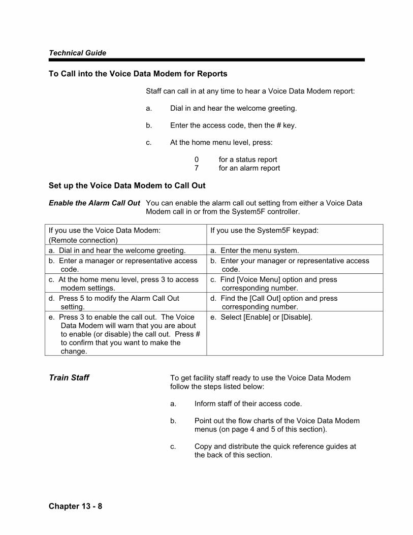
Technical Guide
Chapter 13 - 8
To Call into the Voice Data Modem for Reports
Staff can call in at any time to hear a Voice Data Modem report: a. Dial in and hear the welcome greeting.
b. Enter the access code, then the # key.
c. At the home menu level, press:
0 for a status report 7 for an alarm report
Set up the Voice Data Modem to Call Out Enable the Alarm Call Out You can enable the alarm call out setting from either a Voice Data
Modem call in or from the System5F controller. If you use the Voice Data Modem: (Remote connection)
If you use the System5F keypad:
a. Dial in and hear the welcome greeting. a. Enter the menu system. b. Enter a manager or representative access code.
b. Enter your manager or representative access code.
c. At the home menu level, press 3 to access modem settings.
c. Find [Voice Menu] option and press corresponding number.
d. Press 5 to modify the Alarm Call Out setting.
d. Find the [Call Out] option and press corresponding number.
e. Press 3 to enable the call out. The Voice Data Modem will warn that you are about to enable (or disable) the call out. Press # to confirm that you want to make the change.
e. Select [Enable] or [Disable].
Train Staff To get facility staff ready to use the Voice Data Modem
follow the steps listed below:
a. Inform staff of their access code. b. Point out the flow charts of the Voice Data Modem
menus (on page 4 and 5 of this section).
c. Copy and distribute the quick reference guides at the back of this section.
Communication Capabilities
Chapter 13 - 9
Customize the Ring Pickup Value Default = 1 The ring pickup value controls the number of times the
Voice Data Modem will "ring' before an incoming call will be connected. (You may need to change this value if your facility is using phone switching equipment.)
a. Dial in and hear the welcome greeting. b. Enter a manager or representative access code.
c. At the home menu level, press 3 to access Modem
settings.
d. Press 1 to modify.
e. Enter a new value.
f. Press the # button to save the new value. Customize the Call Out Pre-Delay Default = 30 minutes The overall delay value sets the amount of time that the
Voice Data Modem will wait before calling down the call out list. If no one on the list answers the Voice Data Modem call out, it will wait this same amount of time before calling down the list again.
For example, let's say the System5F has an alarm event.
The Voice Data Modem calls the first person on the list, but there is no answer. It calls the rest of the people on the list. If no one answers, the Voice Data Modem will continue to call out. The delay value establishes a waiting period. If the value is set to 10 minutes, the Voice Data Modem will wait ten minutes after the last call out before it attempts to call down the list again.
To set up the call out phone numbers, use the Strantrol
Virtual Controller (SVC) program (from your computer) or access the System5F facepanel using either a Representative or Manager Access Code.
Customize the Delay #1, #2, #3, #4, #5 and #6 Default = 10 seconds In addition to setting the Overall Delay, you can set the
amount of time that the Voice Data Modem waits between dialing each call out number within the list. For example, if no one answers at phone #1, delay #1 tells the Voice Data Modem to wait before calling phone #2.

Technical Guide
Chapter 13 - 10
The FCC and Your Voice Data Modem
Your new USFilter Stranco Products product has been registered with the Federal Communication Commission (FCC). This product complies with standards in Part 68 of the FCC rules. The FCC requires USFilter Stranco Products to provide you with the following information:
Connection and Use With The FCC requires that you connect your Voice Data Modem the Nationwide Telephone to the nationwide telephone network through a modular Network telephone outlet or jack. The modular telephone outlet or jack
to which the telephone equipment must be connected is a USOC RJ-11C or RJ-11W.
This equipment may NOT be used with Party Line Service or with coin telephone lines.
Notification to the The FCC requires that upon request of you local telephone Telephone Company company, you provide the following information:
A. The "line" (that is, the phone number) to which you will connect the Voice Data Modem, and
B. The telephone equipment's FCC registration
number and ringer equivalence number (REN). These numbers are on the inside of your controller/telephone equipment.
The REN is useful to determine how many devices you may connect to your telephone line and still having them ring when your telephone line is called. In most areas, the sum of all RENs should be 5 or less. You may want to contact your local telephone company.
Repair Instructions If it is determined that your Voice Data Modem is malfunctioning, the FCC requires that it not be used and that it be unplugged from the modular outlet until the problem has been corrected. Repairs to this Voice Data Modem equipment can only be made by the manufacturer or its authorized agents or by others who may be authorized by the FCC. For repair procedures, follow the instructions outlined under the USFilter Stranco Products warranty procedure.
Rights of the Telephone Company If your Voice Data Modem is causing harm to the telephone
network, the telephone company may temporarily discontinue your telephone service. If possible, they will notify you before they interrupt service. If advance notice isn't practical, you will be notified as soon as possible. You will be given the opportunity to correct the problem, and you will be informed of your right to file a complaint with the FCC.


Strantrol® System5F
Technical Guide
SALES/SERVICE
1.866.766.5987 Fax: 815.932.1760
http://www.strancoaquatics.com e-mail: [email protected]
Products manufactured and marketed by United States Filter Corporation (USFilter) and its affiliates are protected by patents issued or pending in the United States and other countries. USFilter reserves the right to change the specifications referred to in this literature at any time without prior notice. STRANTROL is a trademark of United States Filter Corporation and/or its affliates.
Stranco Products Level 1, 6-10 Talavera Road Priory Works, Tonbridge P.O. Box 389 North Ryde, NSW 2113 Kent, TN11 0QL Bradley, IL 60915 U.S.A. Australia United Kingdom 866.766.5987 phone +61.2.9850.2822 phone +44.(0)1732.354888 phone 815.932.8154 phone +61.2.9850.2898 fax +44.(0)1732.354222 fax 815.932.1760 fax
http://www.strancoaquatics.com © 2003 USFilter

Communication Capabilities
Chapter 13 - 1
Lit No. ST-System5F-MAN-Rev 0304