
STR-Series - NIDEC-SHIMPO CORPORATION€¦ · STR-Series Instruction manual. 1 ... • Tu rnoff th...
10
Read carefully this instruction manual before use STR-Series Instruction manual
Transcript of STR-Series - NIDEC-SHIMPO CORPORATION€¦ · STR-Series Instruction manual. 1 ... • Tu rnoff th...

Read carefully this instruction manual before use
STR-SeriesInstruction manual
1
Table of contents 1. Safety precautions........................................................................................................................................2
General ........................................................................................................................................................... 2 Pictograph descriptions .................................................................................................................................. 2
2. Preparation ....................................................................................................................................................3 2-1 Checking the product ........................................................................................................................... 3 2-2 Checking specifications ....................................................................................................................... 3 2-3 Name of parts ...................................................................................................................................... 3
3. Installation .....................................................................................................................................................5 3-1 Packaging ............................................................................................................................................ 5 3-2 Installing place ..................................................................................................................................... 5 3-3 Installing ............................................................................................................................................... 5 3-4 Servo motor assembling process ........................................................................................................ 6
4. Connection and operation ...........................................................................................................................7 4-1 Connection and servo parameter set up .............................................................................................. 7 4-2 Checking out motion ............................................................................................................................ 7 4-3 Normal operation ................................................................................................................................. 7 4-4 Output flange position with servo motor off ......................................................................................... 7 4-5 Adjusting servo motor gain .................................................................................................................. 7 4-6 Operation under cold temperature ....................................................................................................... 7 4-7 Directional relation of input and output rotation ................................................................................... 7 4-8 General operating conditions ............................................................................................................... 7
5. Maintenance ..................................................................................................................................................8 5-1 Regular check up ................................................................................................................................. 8 5-2 Lubricants ............................................................................................................................................ 8
6. Troubleshoot .................................................................................................................................................9
STR-SERIES

1. Safety precautions General
• This instruction manual describes about installation and operation of STR-Series . • The product must be dealt by a person with applicable skill and knowledge. • Read this instruction manual carefully to understand the product in detail. • In case of a need for maintenance or repair work, please contact the sales office. • Keep this instruction manual in a proper place to refer to. • This instruction manual must be delivered to a final customer who operates the product. • For servo motor operation, refer to its instruction manual.
Pictograph descriptions
Pictograph Meaning
Warning This indicates that improper use may lead to serious injury or death.
Caution This indicates that improper use poses a strong risk of injury or damage to property.
Caution
• Check the product has correct specification for an application before use. Improper application may cause malfunction or resulted injury.
• Do not remove serial plate. • Stop operation immediately if there is unusual vibration, noise, temperature rise, or unable to obtain expected performance. • If moving parts of the product interfere or is being constrained improperly, unexpected load acts on servo motor, which
leads to overheating, stop operation immediately if the product does not rotate properly. • Do not touch a motor. • Turn off the main power switch of a servo motor in the case of electric power down. Avoid risk of sudden start after electric
power recovery which can cause injury. • Do not disassemble the product. It can lead to malfunction. • Tighten screws with proper tightening torque by using torque wrench. Apply LOCTITE 242 (recommended) or equivalent
agent when tightening screws to avoid being loosened during operation. Improper tightening can cause failure and resulted injury.
• Use the product with right orientation. Operation with improper orientation can cause failure or oil leak.
Warning • Do not touch moving parts of the product while in operation. It can lead to injuries. • Do not perform maintenance work while electric power is supplied. Unexpected movement by interference may cause injuries. • Transport, installation, operation, or maintenance must be carried out by a person with skill and knowledge. Improper handling may
cause injury or damage to the product. • Do not hang the product by a crane after installing. The product may fall and resulted in injury • Do not use the product for applications which has significant effects to human life, serious risk of death, pollution or environmental
destruction such as following: ・Medical instruments ・Nuclear power devices ・Aerospace devices ・Devices dealing with hazardous materials etc.
2

2. Preparation 2-1 Checking the product
Open the package and check contained items as listed below: • STR main unit + servo motor 1 set • Motor driver 1 • Motor driver cable 1 • Encoder cable1 • Motor fitting parts (motor base, sleeve, guide) 1 set (for customer fitting case) • Instruction manual 1 • Certification of guarantee 1
2-2 Checking specifications
Read a product code on serial plate to check if a specification is correct.
【Product code example】
Orientation code: Proper orientation determined at time of order.1 2 3 4 5 6 0
Orientation varies
W side grounded
V side grounded
U side grounded
T side grounded
R side grounded
S side grounded
2-3 Name of parts
Oil level
Output flange
DrainHousing
Counter bore(s)
Guide clamp screwMotor base
Guide
Guide fix screw
Servo motor Clamp collar
adjusting hole
STR 1 0 0 0 8 0 E R
Gearbox mount side (Right [R], Left [L])
Reducer type (inline [V], Right-angle [E], None [N])
(Variety ranging from 15:1 - 2000:1)Reduction ratio
Actuator size (040, 063, 080, 100, 125, 160, 250)
Model name STR product
1 4 B K 1 2 0 0
Surface names
T side S side
U side R side
V side
W side
3
STR-SERIES
3. Installation 3-1 Packaging
The product is shipped after quality inspection.
� Servo motor is assembled when shipped. � Servo deriver and cables are not connected.
3-2 Installing place
The product should be installed in a place satisfying following conditions:
� Environment temperature from +5 to +40 ºC � Humidity under 85% (no condensation) � Non vacuum or extreme pressure � No exposure for water, oil, chemicals, dusts, and so on. � No existence of explosive gas, other hazardous gas, or radioactive materials. � No direct sunlight. � Excessive shock or force does not act � Grounded from electric current. � Minimum electromagnetic noise (beware for welding machines). � Easy to carry out maintenance and checking oil level and drain.
3-3 Installing
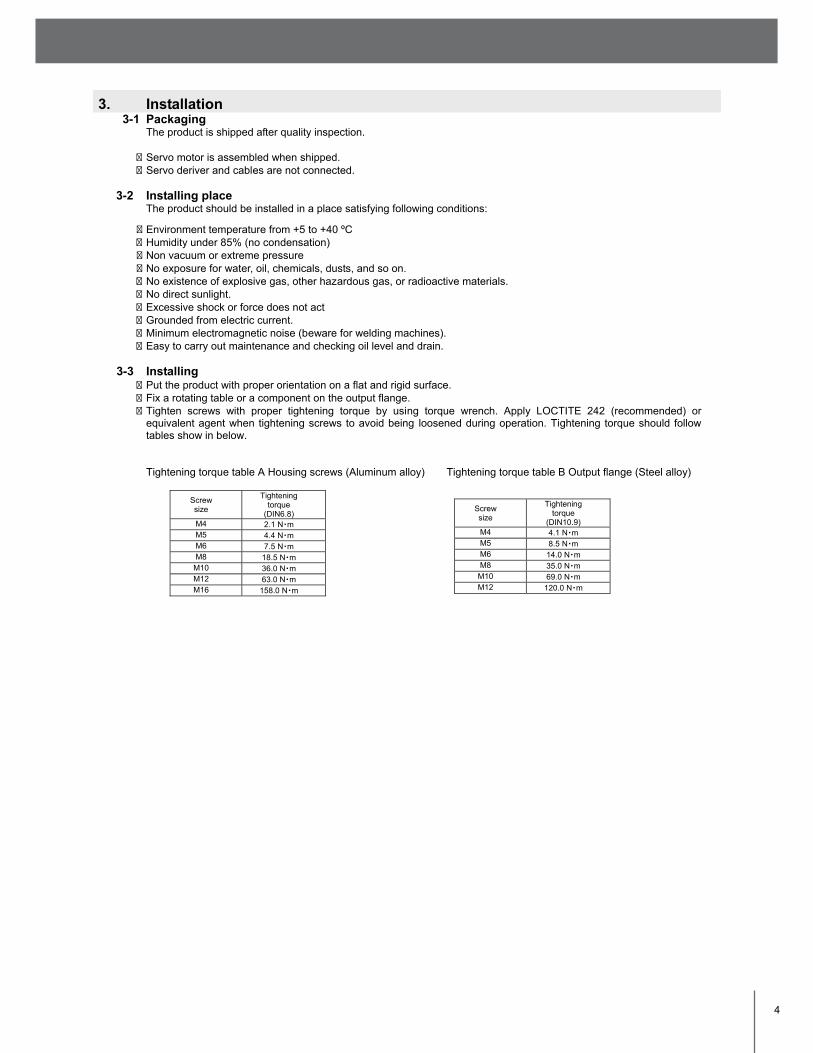
� Put the product with proper orientation on a flat and rigid surface. � Fix a rotating table or a component on the output flange. � Tighten screws with proper tightening torque by using torque wrench. Apply LOCTITE 242 (recommended) or
equivalent agent when tightening screws to avoid being loosened during operation. Tightening torque should follow tables show in below. Tightening torque table A Housing screws (Aluminum alloy) Tightening torque table B Output flange (Steel alloy)
Screw size
Tightening torque
(DIN6.8) M4 2.1 N・m M5 4.4 N・m M6 7.5 N・m M8 18.5 N・m
M10 36.0 N・m M12 63.0 N・m M16 158.0 N・m
Screw size
Tightening torque
(DIN10.9) M4 4.1 N・m M5 8.5 N・m M6 14.0 N・m M8 35.0 N・m
M10 69.0 N・m M12 120.0 N・m
4

3-4 Servo motor assembling process
In the case of assembling servo motor into STR at customer’s site, please follow this assembling process.
• Improper assembling servo motor cannot make a performance with a high capability.
• Apply LOCTITE 242 (recommended) or equivalent agent when tightening screws to avoid being loosened during operation. Improper tightening can cause failure and resulted injury.
1. Fix the motor onto the motor base
Fix the motor and the motor base. Also, fit a sleeve on the motor shaft with a little bit of turbine oil. (Never apply molybdenum grease or other grease which contains extreme pressure additive.) Side of the sleeve and the motor shaft should be aligned. (If the diameter of the motor shaft and the inside diameter of the input shaft are same size, it is unnecessary a sleeve.)
2. Put a clamp collar onto the input shaft
Fix the clamp collar by tightening screws loosely. (Do not tighten screws too much.) Side of the clamp collar and the input shaft should be aligned. Screws should face R side of the housing.
3. Insert the motor shaft When insert the motor shaft, slit of the sleeve and clamp collar should be aligned as shown in the figure.
4. Make 0.5 mm gap between housing and motor base
Use filler gauge or substitution to measure 0.5 mm gap. Keep the gap until tighten clamp collar screws. Using 0.5 mm shims required.
5. Tighten the clamp collar screws Tighten clamp collar screws evenly. Tightening torque must follow the tightening torque table on previous page.
6. Clamp the guide with motor base Insert the guide into a slit of motor base. Guide should contact to the housing surface. After that, tighten the guide clamp screw to hold the guide. Adjust the screw to allow guide be able to slide.
7. Fix the guide to the housing
Tighten screws to fix the guide.
8. Fix the motor base to the housing
Tighten screws much more to fix the motor base. Apply LOCTITE 242 (recommended) or equivalent agent and tighten their screws again.
Sleeve
0.5mm gap
Guide
Motor base
Aligned
NOTE: IF INSTALLING SHIMPO REDUCER WITH THE STR, DISRE-GARD THIS SECTION AND FOLLOW STANDARD ASSEMBLY INSTRUCTIONS FOR OUR SERVO GRADE PLANETARY PRODUCTS.
5
STR-SERIES

4. Connection and operation 4-1 Connection and servo parameter set up
Connection of a servo motor, an amplifier, and a controller must follow the instruction manual of each component. After connection, set servo parameters depending on conditions of operation, i.e. speed, inertia, pattern of motion, etc. Parameter set up and programming must follow the instruction manual of a servo motor, an amplifier, or a controller.
4-2 Checking out motion
After setting up a servo motor, run a motor at low speed to check its motion. Interference, excessive inertia, or other improper condition can lead to overheat and malfunction of a motor. If expected motion is not obtained, stop operation immediately, and check an operation condition.
4-3 Normal operation
Start and stop is operated by a programmable controller, PC, or other control units. Refer to instruction manual of a controller for detailed control method.
Do not start and stop by switching main power.
4-4 Output flange position with servo motor off Because of STR high efficiency, it does not have “self-lock” property. If it is required to ensure the output flange position with servo motor power off, it is necessary to use brake type servo motor, or other brake, clamping system on output axis for safety.
To ensure the output flange position with servo motor power off, it is necessary to use brake or clamping system for safety.
4-5 Adjusting servo motor gain Adjustment a speed loop gain, a speed loop integral time constant and a position loop gain must follow the procedure. (See the instruction manual of servo motor in detail.)
Step Description
1 Adjust a moment of inertia for load. 2 Decrease a position loop gain and increase a speed loop integral time constant. 3 Increase a speed loop gain until the mechanical system does not vibrate and noise. 4 Decrease a speed loop integral time constant until the mechanical system does not vibrate and noise. 5 Adjust a torque command filter time constant so that no vibration occurs. 6 Repeat the steps 2, 3 and 4, then reduce the value for 10 to 20% 7 In case of the position control, increase a position loop gain until the mechanical system does not vibrate and
noise.
4-6 Operation under cold temperature Under cold temperature, motor speed can be affected by increased lubricant viscosity. In such a case, warm up operation is recommended until STR reaches about 15 ºC.
4-7 Directional relation of input and output rotation
For standard STR, relation of rotation is as shown in below figure. For clockwise input rotation with looking from T side, output shaft produces clock wise rotation looking from V side.
Input and output rotation
4-8 General operating conditions
The product must not exceed the operating conditions, such as rated torque, revolution speed, and so on, which specified in catalogue or specification drawings. Improper operating condition can lead to failure of the product.
6
5. Maintenance 5-1 Regular check up
For safety, following should be checked regularly • Loosened screws • Noise, excessive heat • Oil seal conditions (wearing, cracks) • Oil leak
5-2 Lubricants
• Although high quality and long life lubricant is used for STR-Series, it should be refilled every 3,000 hours of operation.
• Condition of a lubricant can be checked from oil level gauge. Checking should be carried out when the product is stopped. Check color and amount, and if there are significant changes, refill the lubricant no matter what operation hours.
• Small bubbles, which can appear in oil during operation, does not affect its lubrication property.
Use the following lubricant for refill. Standard lubricant: Mobil SHC629 (VG150) Use of different oil can cause wearing or other troubles. For grease lubrication (special requirement) Type of grease is specified in a specification drawing. Generally, no refilling is required for grease lubrication. If there is a need for refilling grease, please contact to NIDEC-SHIMPO.
It is not possible to replace oil with grease or vice versa.
7
STR-SERIES

6. Troubleshoot
Check the following first in the case of trouble. stniop kcehC snoitidnoC
STR does not run with starting operation
� Motor, amplifier, and controller are connected properly? (→ 4-1) � Servo parameters are correct? (→ 4-1, 4-4) � No malfunction of motor, amplifier, or controller? � No interference of an output? (→ 4-2) � Is clamp collar tightened properly? (→ 3-4)
Speed is slow. Servo error appears.
� Isn’t temperature low? (→ 4-6) � Servo parameters are correct? (→ 4-4) � No interference of an output? (→ 4-2) � No excessive load or inertia? � Is clamp collar tightened properly? (→ 3-4)
Over shoot � Servo parameters for inertia correct? (→ 4-1, 4-4)
� No excessive load or inertia? � Is clamp collar tightened properly? (→ 3-4)
Output vibration. Long settling time. Motor noise.
� Is servo gain adjusted properly? (→ 4-4) � Tightening pressure of guide clamp screw proper? (→ 3-4)
Irregular motion � Strong electric, magnetic noise existence (→ 3-2)
� No malfunction of motor, amplifier, or controller?
8

DISTRIBUTED BY:
NIDEC-SHIMPO CORPORATION • 1701 Glenlake Avenue, Itasca, IL 60143 USA • P: (800) 842-1479 • F: (630) 924-7382 • www.drives.nidec-shimpo.com