STORM WATER FACILITY CONDITION SURVEY FIELD MANUAL …
42
PREPARED BY: BUREAU OF MAINTENANCE AND OPERATIONS ASSET MANAGEMENT DIVISION P.O. Box 3437 HARRISBURG, PENNSYLVANIA 17105-3437 (717) 787-6899 STORM WATER FACILITY CONDITION SURVEY FIELD MANUAL PUBLICATION 73 APRIL 2021 PUB 73 (4-21)
Transcript of STORM WATER FACILITY CONDITION SURVEY FIELD MANUAL …

STORM WATER FACILITY CONDITION SURVEY FIELD MANUAL
PUBLICATION 73
APRIL 2014
PREPARED BY: BUREAU OF MAINTENANCE AND OPERATIONS
ASSET MANAGEMENT DIVISION P.O. Box 3437
HARRISBURG, PENNSYLVANIA 17105-3437 (717) 787-6899
STORM WATER FACILITY CONDITION SURVEY FIELD MANUAL
PUBLICATION 73
APRIL 2021
PUB 73 (4-21)


COMMONWEALTH OF PENNSYLVANIA DEPARTMENT OF TRANSPORTATION
STORM WATER FACILITY CONDITION SURVEY FIELD MANUAL
APRIL 2021
PUBLICATION 73


i
TABLE OF CONTENTS
INTRODUCTION ..................................................................................................................1
SURVEY TECHNIQUES AND PROCEDURES..............................................................2
GENERAL: ..............................................................................................................................2 UNDETERMINED PHYSICAL OR STRUCTURAL CONDITION: ..................................................3 CONTINUOUS OR UNDETERMINED INLET OR OUTLET: .........................................................3 RAMPS: ..................................................................................................................................3
DUTIES AND RESPONSIBILITIES..................................................................................3
SAFETY FIRST: .......................................................................................................................3 THE DRIVER: .........................................................................................................................3 THE EVALUATOR:..................................................................................................................4 QUESTIONS FROM THE PUBLIC: .............................................................................................4
EQUIPMENT..........................................................................................................................5
COMPLETION OF CONDITION SURVEY INPUT FORM ........................................6 IDENTIFICATION SECTION: ....................................................................................................6 EVALUATION SECTION: .........................................................................................................6 STORM WATER FACILITY CONDITION SURVEY FORM .......................................................10
DEFINITIONS ......................................................................................................................11
INVENTORY IDENTIFICATION GUIDE ....................................................................13
PIPE OR STRUCTURE STYLES...............................................................................................14 POSITION ..............................................................................................................................19 MEASURING INVERT DEPTH................................................................................................21 INLET/OUTLET TYPES .........................................................................................................22
CONDITION IDENTIFICATION GUIDE .....................................................................27
PHYSICAL CONDITION .........................................................................................................28 STRUCTURAL CONDITION ...................................................................................................30 FLOW CONDITION ................................................................................................................32 ROADWAY DEFLECTION......................................................................................................34 DITCH EROSION ...................................................................................................................35

1
Introduction This manual is for use with the Pennsylvania Department of Transportation’s Pavement Condition Survey. The Pavement Condition Survey is a distress survey that provides quantified, location specific condition data on Pennsylvania’s network of approximately 40,000 centerline miles of state-owned highways. The data collected is used for the following: 1. To provide a uniform statewide condition evaluation that would improve decision
making. 2. To provide management with information and tools to monitor condition of the
network, assess future needs, establish county condition rankings and optimize investments.
3. To provide condition information to fulfill the requirements of Act 68 (1980) which
requires the allocation of maintenance funds to the individual counties based on needs.
4. To provide information for monitoring the performance of various pavement designs,
rehabilitation and maintenance techniques. 5. To provide information for identifying candidate projects for maintenance and
betterment programs. This manual covers storm water facility conditions.

2
Survey Techniques And Procedures
General: The storm water facility survey is both an inventory of the various storm water elements along Pennsylvania’s highways and a survey of their conditions. The storm water facility survey includes all elements along and under the roadways on all state routes. A two-person survey team will drive slowly, and walk where necessary and appropriate, along the shoulder of each segment. The survey team will consist of a Driver and a Storm Water Facility Evaluator. When walking, the Driver will assist the Evaluator. It will be necessary to walk through areas where the storm water features are located in order to properly locate and assess the features. The survey team may drive between storm water features. The segments to be surveyed will be pre-determined. The electronic Condition Survey Input Forms – Storm Water are preloaded with the segment identification and known storm water elements. Once in the field, the Storm Water Facility Evaluator, with the Driver’s assistance, will verify the location of those items shown on the forms. The survey team shall create new forms to correct any information on the preloaded survey forms that disagree with the field conditions. This situation may occur when new storm water features are installed, removed or repaired since the previous survey. Storm water features to note include the location of slope or cross pipes and other structures, inlet/outlet ditches, and the beginning and end of parallel pipes and ditches. The survey team will note the style of storm water structure, type of material, type of coating, physical and structural conditions and the extent of ditch erosion where applicable. The survey team will complete the electronic Condition Survey Input Form – Storm Water at the end of each parallel pipe or ditch, or after examining each individual storm water structure. All beginning and ending locations of the storm water elements should be listed as the “offset” from the beginning of each STAMPP segment. The effective and eroded lengths of outlet ditches are the exception to this rule and should be recorded in lineal feet measured along the ditch centerline. Each survey vehicle should have an automated distance measuring instrument (DMI) installed. The survey team should use the DMI to measure segment offsets. All offsets should be measured and recorded with reference to increasing segment numbers. Many instances will be encountered in the performance of the Storm Water Facility Survey that do not exactly conform to the general descriptions or instructions in this manual. Some of these are listed below, along with recommended procedures. For other unusual circumstances, judgment should be exercised and a note added to the survey form.

3
Undetermined Physical or Structural Condition: There will be instances where it is physically impossible to assess the physical or structural condition of the pipe or structure. An inlet may be clogged so that the invert of the pipe or inlet base cannot be seen; an inlet grate is too heavy to lift to determine the physical or structural condition of the inlet. The survey team should code the physical or structural conditions for these elements as “4”, “5”, “6”, or “7” for undetermined (as appropriate).
Continuous or Undetermined Inlet or Outlet: Typical closed storm sewer systems are continuous with the culverts and inlets interconnected until a suitable outlet is available. The survey team should code the inlet in a closed storm sewer system as the specific type (“0” through “4”) and the outlet as a “5” for continuous. A storm water system may have no apparent outlet because it has covered over or extends beyond the right-of-way. The survey team should code the inlet or outlet type that cannot be determined as “6” for undetermined. As-built plans can be helpful in locating inlets and outlets in these situations.
Ramps: Do not survey storm water systems along ramps. Ramps are not part of the condition survey.
Duties and Responsibilities
Safety First: The Survey Team’s primary responsibility is SAFETY! The information being collected in the Storm Water Facility Survey is very important, however, it is not more important than the safety and lives of the survey team. The survey team should always be alert for potentially dangerous situations and always obey all traffic laws.
The Driver: The Driver’s primary responsibility is to operate the survey vehicle in a safe, courteous manner in accordance with the laws of the Commonwealth. The Driver is responsible for

4
determining the team’s location using fixed reference points (intersections, bridges, etc.), the DMI and Straight Line Diagram (SLD) printouts. The Driver shall keep records to assure that all segments are covered as planned and determine the team’s routing to minimize non-productive travel. The Driver will assist the Evaluator whenever the team is walking the segment to conduct the survey.
The Evaluator: The Evaluator shall observe the locations, types and conditions of the various storm water features being inventoried and surveyed with assistance from the Driver. The Evaluator shall complete the electronic Condition Survey Input Form. A separate form shall be used for each pipe/structure location. The heading information will be preloaded for each location as discussed previously. The Evaluator is responsible for completion of any missing information including date and observer. Each form provides space for one set of storm water facility information. Where no installations exist in a segment, the Evaluator should check “No Drainage” on the form. If there are more storm water features than available forms, new forms shall be created. The Evaluator must complete the heading information on the new forms. The Evaluator should keep a list of obvious discrepancies in the SLD or County maps. Report these discrepancies to the District RMS Coordinator. Serious hazards to the motoring public should be reported to the RMS Coordinator as soon as possible. The RMS Coordinator will contact the appropriate District unit to address the issue. If the RMS Coordinator cannot be reached, any hazard or issue that requires immediate corrective action should be reported to the County Maintenance Manager.
Questions from the Public: The survey team should answer questions from the public honestly and diplomatically to maintain good public relations. Inform the citizen that a condition survey is being conducted to better enable the Department to maintain the storm water features. Politely direct any specific complaints to the Assistant District Engineer for Maintenance or the County Maintenance Manager. Keep the appropriate phone numbers on hand for these occasions.

5
Equipment The following list of equipment is necessary to the proper performance of the Storm Water Facility Condition Survey.
1. State Car equipped with: a. Digital distance measuring instrument which accurately determines
distance, b. Amber flashing warning beacon, c. Survey Sign on back of vehicle (ROAD SURVEY or PAVEMENT
SURVEY)
2. County Maps (paper or digital)
3. Straight Line Diagrams (paper or digital)
4. Storm Water Facility Condition Survey Field Manual
5. Clipboard
6. STAMPP application on tablet or laptop PC with eSTAMPP forms preloaded
7. Pens, pencils, and tablet paper for taking notes
8. Hard hats and safety vests
9. Ten-foot (preferred) or six-foot rule
10. File folders
11. String line at least 15 feet long
12. 100-foot tape measure
6
Completion of Condition Survey Input Form
Identification Section: Most of this section (see the form on page 10) will be preloaded. The information contained in the identification section should be quickly reviewed to make sure that the information is correct. That information is:
Segment Identifier – There are three fields for the segment identifier, in the same format as the Department’s other databases, consisting of: County Name State Route Number Segment Number Segment Length – The length of the segment in feet. Direction – The direction of the portion of the pavement being evaluated. Beginning Description – Narrative description of the segment beginning point Ending Description – Narrative description of the segment ending point Observers – The code numbers of the Survey Team; Observer 1 is the Evaluator, Observer 2 is the Driver Survey Date – The date the segment is surveyed (shown in the body of the form)
Evaluation Section: The storm water inventory and condition survey will consist of a survey of storm water facilities along the roadside and in the median on state routes. The survey will include all pipe and storm water structures which are less than 8 feet in length measured parallel to the roadway centerline, inlets and outlets from those pipes and structures, and outlet and parallel ditches. Information for pipes and structures which are 8 feet or greater in length are included in the Bridge Management System (BMS) and should not be duplicated. Record the actual length of the pipe or structure on the survey form if it is determined to meet the criteria for being inventoried; the actual length may not be measured parallel to the centerline of the roadway.

7
Each form provides space for one storm water feature. The Evaluator should check “No Drainage” on the survey form whenever there are no storm water features in the segment to inventory. Create new forms when additional forms are needed. Enter the segment identification information on the new blank form. Information for each pipe or storm water structure, including its inlets and/or outlets, shall be recorded. Enter parallel pipe or ditches on a separate survey form. Identify locations of cross pipe and storm water structures by segment offsets. The Evaluator should select the appropriate numerical code (or text description) for all survey items for each pipe or structure and inlets or outlets. Enter only the information relative to the begin and end limits, flow condition and extent of erosion for parallel ditches. Survey cross pipes on roadways with four or more lanes, where the pipe extends under all traffic lanes, with each segment in which it is located. The Evaluator should provide as much information as possible when surveying a “continuous” storm water system. Provide the actual “type” coding for the inlets only in a continuous system and code the outlets as “5” for continuous (until the final outlet of the system is reached). See the example:
Complete the form as follows (Example for inlet and outlet only; other data will be required during the survey. Actual form layout will vary.):
INLET S OUTLET S P T S C F C T S C F CEND I END T O - - - - - Y T O L O Y T O L O - - - - -
SEGMENT D SEGMENT Y S P R N O N P R N O NOFFSET E OFFSET L I E U D W D E U D W D
E T C I I C I II T T T T T TO U I I U I IN R O O R O O
E N N E N N0200 R 0250 0 1 - - - - - 0 0 0 5 0 0 - - - - -0250 R 0365 0 1 - - - - - 0 0 0 2 0 0 - - - - -
PIPE/STRU INLET OUTLET
Endwall Drop w/out grate
Drop w/out grate
Offset 200 Offset 250 Offset 365
Inlet = 0 Outlet = 5 Inlet = 0 Outlet = 2
8
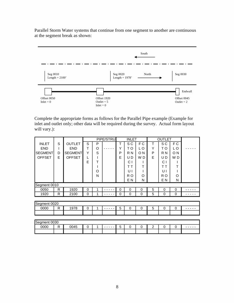
Parallel Storm Water systems that continue from one segment to another are continuous at the segment break as shown:
Complete the appropriate forms as follows for the Parallel Pipe example (Example for inlet and outlet only; other data will be required during the survey. Actual form layout will vary.):
INLET S OUTLET S P T S C F C T S C F CEND I END T O - - - - - Y T O L O Y T O L O - - - - -
SEGMENT D SEGMENT Y S P R N O N P R N O NOFFSET E OFFSET L I E U D W D E U D W D
E T C I I C I II T T T T T TO U I I U I IN R O O R O O
E N N E N N
0050 R 1920 0 1 - - - - - 0 0 0 5 0 0 - - - - -1920 R 2100 0 1 - - - - - 0 0 0 5 0 0 - - - - -
Segment 00200000 R 1978 0 1 - - - - - 5 0 0 5 0 0 - - - - -
Segment 00300000 R 0045 0 1 - - - - - 5 0 0 2 0 0 - - - - -
PIPE/STRU INLET OUTLET
Segment 0010
Offset 1920 Outlet = 5 Inlet = 0
Seg 0010 Length = 2100’
Seg 0020 Length = 1978’
Seg 0030
Offset 0050 Inlet = 0
North
South
Offset 0045 Outlet = 2
Endwall

9
Cross Pipes on divided roads that continue from one direction (segment) to the other direction (segment) are also continuous as shown in the example:
Complete the appropriate forms as follows for the Cross Pipe example (Example for inlet and outlet only; other data will be required during the survey. Actual form layout will vary):
INLET S OUTLET S P T S C F C T S C F CEND I END T O - - - - - Y T O L O Y T O L O - - - - -
SEGMENT D SEGMENT Y S P R N O N P R N O NOFFSET E OFFSET L I E U D W D E U D W D
E T C I I C I II T T T T T TO U I I U I IN R O O R O O
E N N E N N
0000 R 1750 0 1 - - - - - 0 0 0 5 0 0 - - - - -1750 R 1765 0 0 - - - - - 0 0 0 5 0 0 - - - - -
Segment 00211765 R 1780 0 0 - - - - - 5 0 0 5 0 0 - - - - -1780 L 1857 0 1 - - - - - 0 0 0 5 0 0 - - - - -
Segment 00250000 L 1650 0 1 - - - - - 5 0 0 2 0 0 - - - - -
PIPE/STRU INLET OUTLET
Segment 0020
Seg 0020 Length = 1857’
Seg 0024 Length = 1850’
Seg 0030
Seg 0021 Length = 1857’
Seg 0025 Length = 1850’
Seg 0031
Offset 0000 Inlet = 0
Offset 1750 Outlet = 5 Inlet = 0
Offset = 1780 Outlet = 5 Inlet = 0
Offset = 1650 Outlet = 2
North
South Seg 0015

10
Storm Water Facility eSTAMPP Survey Form
(Layout may change based on current version of the application.)
11
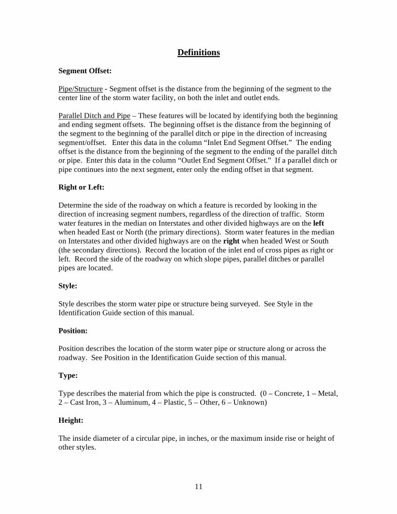
Definitions Segment Offset: Pipe/Structure - Segment offset is the distance from the beginning of the segment to the center line of the storm water facility, on both the inlet and outlet ends. Parallel Ditch and Pipe – These features will be located by identifying both the beginning and ending segment offsets. The beginning offset is the distance from the beginning of the segment to the beginning of the parallel ditch or pipe in the direction of increasing segment/offset. Enter this data in the column “Inlet End Segment Offset.” The ending offset is the distance from the beginning of the segment to the ending of the parallel ditch or pipe. Enter this data in the column “Outlet End Segment Offset.” If a parallel ditch or pipe continues into the next segment, enter only the ending offset in that segment. Right or Left: Determine the side of the roadway on which a feature is recorded by looking in the direction of increasing segment numbers, regardless of the direction of traffic. Storm water features in the median on Interstates and other divided highways are on the left when headed East or North (the primary directions). Storm water features in the median on Interstates and other divided highways are on the right when headed West or South (the secondary directions). Record the location of the inlet end of cross pipes as right or left. Record the side of the roadway on which slope pipes, parallel ditches or parallel pipes are located. Style: Style describes the storm water pipe or structure being surveyed. See Style in the Identification Guide section of this manual. Position: Position describes the location of the storm water pipe or structure along or across the roadway. See Position in the Identification Guide section of this manual. Type: Type describes the material from which the pipe is constructed. (0 – Concrete, 1 – Metal, 2 – Cast Iron, 3 – Aluminum, 4 – Plastic, 5 – Other, 6 – Unknown) Height: The inside diameter of a circular pipe, in inches, or the maximum inside rise or height of other styles.

12
Width: The maximum horizontal dimensions between inside walls, in inches. Do not make this measurement for circular pipes. Length: The distance along the center line of the pipe or structure from inlet end to outlet end, measured in feet. Invert Depth: Cross Pipes and Structures – Vertical distance between the flow line of the pipe or structure to a point equal to the elevation of the roadway centerline, measured in feet. Make this measurement within 6 feet of the pipe or structure on the outlet end. See page 21 for an example of measuring the invert depth. Parallel Pipe – Vertical distance from the flow line to the elevation of the pavement, shoulder or ground above it. Slope Pipes – Not applicable; leave blank. Flow Line: The surface of the water flowing through the pipe or structure. Coating: The material used to coat the inside surface of the pipe or structure other than galvanizing or other metal coatings. (0 – None, 1 – Asphalt, 2 – Epoxy, 3 – Polymer, 4 – Unknown) Outlet Ditch: A human-made channel beyond 15 feet of the outlet end of the storm water structure. Measure the length of the outlet ditch in feet from the structure or pipe outlet, minus the first 15 feet. The total shall not exceed 200 feet.

13
INVENTORY IDENTIFICATION GUIDE

14
Pipe or Structure Styles Style Type “0” – A Circular Pipe with a maximum inside diameter of less than 8 feet.
Style Type “1” – An Elliptical Pipe or Pipe-Arch with a maximum inside width of less than 8 feet.

15
Style Type “2” – A Box Culvert or Box Structure with a maximum inside width of less than 8 feet.

16
Style Type “3” – A Multiple Pipe Facility is a series of two or more pipes where the distance between individual pipes is less than or equal to the inside width or diameter of the pipes. Enter the centerline of the group of pipes on the inlet end as the beginning segment offset. Enter the centerline of the group of pipes on the outlet end as the ending segment offset. Consider each pipe as a separate storm water facility, and record as such, if the distance between pipes is more than the inside width or diameter. Use the largest pipe diameter, if the group contains more than one size pipe, to determine whether it is a Multiple Pipe Facility.
17
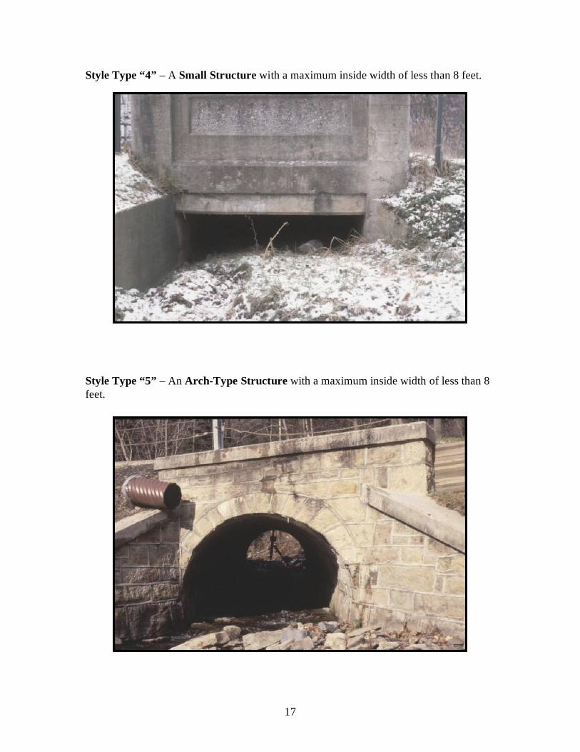
Style Type “4” – A Small Structure with a maximum inside width of less than 8 feet.
Style Type “5” – An Arch-Type Structure with a maximum inside width of less than 8 feet.

18
Style Type “6” – An Other style of storm water structure that does not meet the definitions of Styles 0 through 5 and Style 7. Style Type “7” – A Parallel Ditch is a human-made water course generally running parallel to the roadway, with a minimum 18-inch defined flat bottom, designed to lead water to the nearest storm water course. Do not include V-Ditches adjacent to shoulder areas or in swale areas.
Style Type “8” – Undetermined. Use only when the style cannot be determined due to depth of fill or when the pipe/structure cannot otherwise be safely evaluated.
19
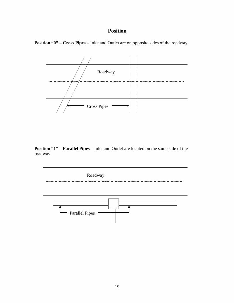
Position Position “0” – Cross Pipes – Inlet and Outlet are on opposite sides of the roadway. Position “1” – Parallel Pipes – Inlet and Outlet are located on the same side of the roadway.
Cross Pipes
Roadway
Parallel Pipes
Roadway

20
Position “2” – Slope Pipes – Pipes generally installed on vertical slopes. These pipes make an angle of at least 45° with the surface of the roadway. Position “3” – Perpendicular Pipe – The pipe leaves or enters the side of the roadway at 90° (between 45° and 135°). The inlet or outlet may be located on the parallel pipe next to the roadway.
Roadway Slope Pipe
Roadway
Perpendicular Pipe

21
Measuring Invert Depth
Example of Measuring Invert Depth

22
Inlet/Outlet Types Inlet/Outlet Type “0” – Drop Inlet Without Grate Precast or cast-in-place concrete or masonry box type structure without a grate, carrying inlet or outlet storm water flow.

23
Inlet/Outlet Type “1” – Drop Inlet With Grate Precast or cast-in-place concrete or masonry box type structure with a grate, carrying inlet or outlet storm water flow.
Inlet/Outlet Type “2” – Endwall Any structure of brick, stone or concrete, having one or more walls, with or without a masonry bottom.

24
Inlet/Outlet Type “3” – Flared End Section A concrete or metal flared or sloped end section of pipe.
Inlet/Outlet Type “4” – Ditch Only The area located within 15 feet of the outlet end of a pipe or structure and 1 foot into the pipe or structure.

25
Inlet/Outlet Type “5” – Continuous A system of two or more pipes where successive pipes outlet directly into the inlet of the next pipe in the system. The outlet is recorded as type “5” while the inlet is recorded as the type “0” through “4” throughout the continuous system. The final outlet is recorded as type “0” through “4”. Inlet/Outlet Type “6” – Undetermined The inlet end or outlet end of a pipe cannot be determined.
Outlet Inlet Outlet Inlet
Flow
“Continuous” Type 5
“Continuous” Type 5
Inlet

26
(This page intentionally left blank)

27
CONDITION IDENTIFICATION GUIDE

28
Physical Condition Condition “0” – Approaching original condition – like new, no defects. Condition “1” – Discoloration, slight spalling of mortar, minor surface rust or scale
which could include minor pitting, slight loss of interior protection.
29
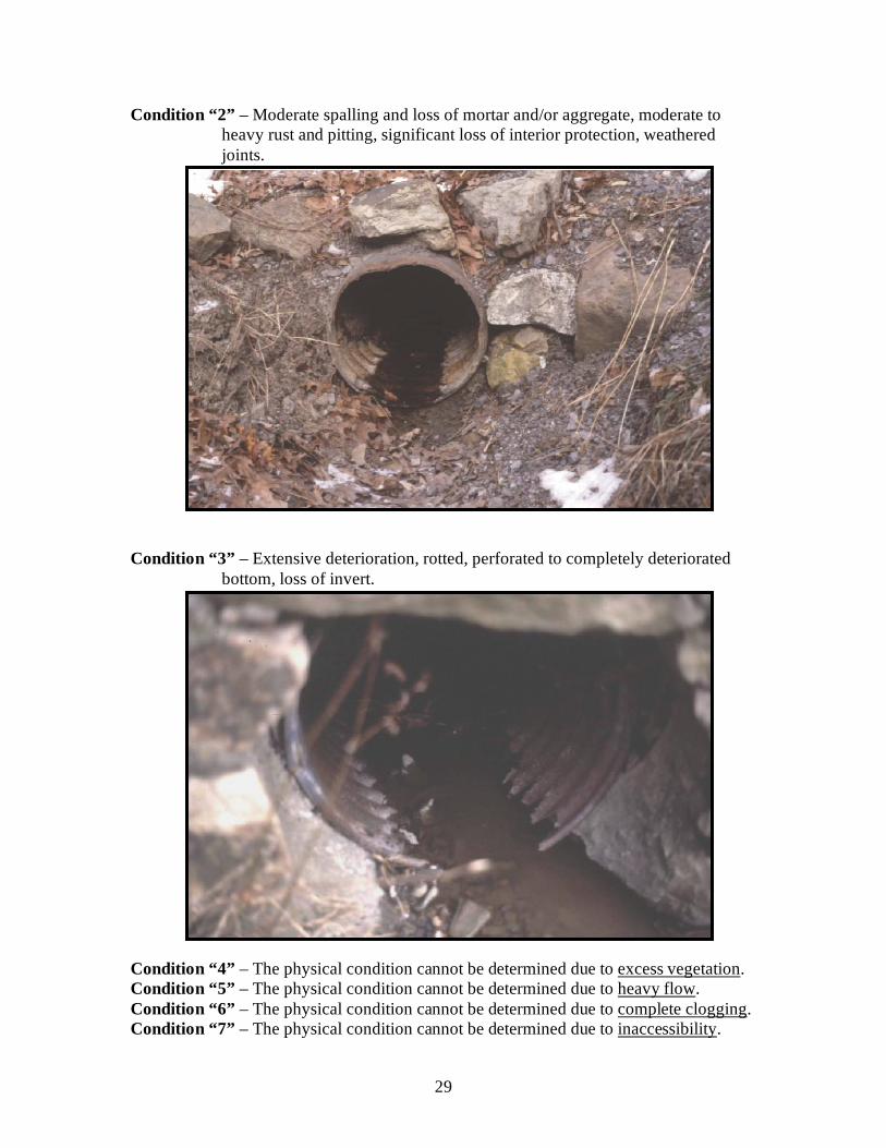
Condition “2” – Moderate spalling and loss of mortar and/or aggregate, moderate to heavy rust and pitting, significant loss of interior protection, weathered joints.
Condition “3” – Extensive deterioration, rotted, perforated to completely deteriorated
bottom, loss of invert.
Condition “4” – The physical condition cannot be determined due to excess vegetation. Condition “5” – The physical condition cannot be determined due to heavy flow. Condition “6” – The physical condition cannot be determined due to complete clogging. Condition “7” – The physical condition cannot be determined due to inaccessibility.

30
Structural Condition Condition “0” – No displacement, as installed, good condition. Condition “1” – Pipe sag or structural components displaced <20°.
Condition “2” – Pipe sag or structural components displaced ≥ 20° joint separation,
scouring.

31
Condition “3” – Completely deteriorated, collapsed or failed.
Condition “4” – Structural condition cannot be determined due to excess vegetation. Condition “5” – Structural condition cannot be determined due to heavy flow. Condition “6” – Structural condition cannot be determined due to complete clogging. Condition “7” – Structural condition cannot be determined due to inaccessibility.
32
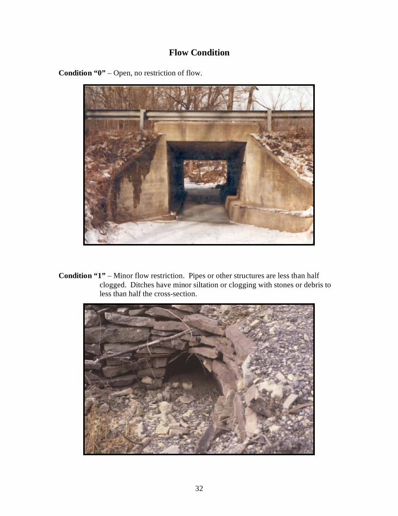
Flow Condition Condition “0” – Open, no restriction of flow.
Condition “1” – Minor flow restriction. Pipes or other structures are less than half
clogged. Ditches have minor siltation or clogging with stones or debris to less than half the cross-section.
33
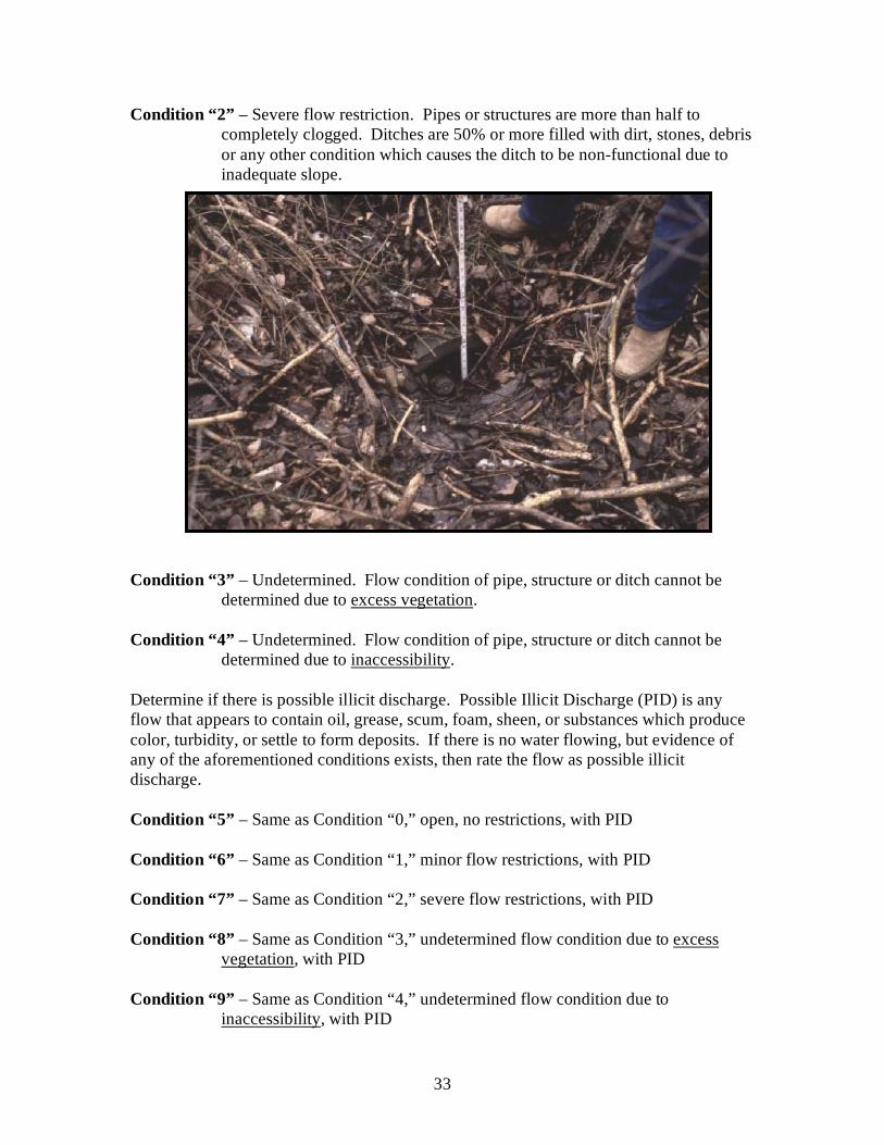
Condition “2” – Severe flow restriction. Pipes or structures are more than half to completely clogged. Ditches are 50% or more filled with dirt, stones, debris or any other condition which causes the ditch to be non-functional due to inadequate slope.
Condition “3” – Undetermined. Flow condition of pipe, structure or ditch cannot be
determined due to excess vegetation. Condition “4” – Undetermined. Flow condition of pipe, structure or ditch cannot be
determined due to inaccessibility. Determine if there is possible illicit discharge. Possible Illicit Discharge (PID) is any flow that appears to contain oil, grease, scum, foam, sheen, or substances which produce color, turbidity, or settle to form deposits. If there is no water flowing, but evidence of any of the aforementioned conditions exists, then rate the flow as possible illicit discharge. Condition “5” – Same as Condition “0,” open, no restrictions, with PID Condition “6” – Same as Condition “1,” minor flow restrictions, with PID Condition “7” – Same as Condition “2,” severe flow restrictions, with PID Condition “8” – Same as Condition “3,” undetermined flow condition due to excess
vegetation, with PID Condition “9” – Same as Condition “4,” undetermined flow condition due to
inaccessibility, with PID

34
Roadway Deflection Condition “0” – None. No deflection in the road surface to ≤1” surface distress is
evident. Condition “1” – Greater than 1” surface distress is present.
Deflection

35
Ditch Erosion Condition “0” – None. Ditch is properly shaped.
Condition “1” – The ditch flow line is eroded with scouring less than 12 inches in depth
or width from the projected flow line.

36
Condition “2” – The flow line is eroded with scouring 12 inches or more in depth or
width from the projected flow line.
Note: Measure and record the most severe eroded length of the ditch.