STLR 06 Catalog Turning I - Proinmar · Turning We, as Stellram employees, are responsible for...
280
TURNING CATALOGUE Stellram ® turning systems for all your turning requirements.
Transcript of STLR 06 Catalog Turning I - Proinmar · Turning We, as Stellram employees, are responsible for...

TURNING CATALOGUE
Stellram® turning systems forall your turning requirements.

Turning
We, as Stellram employees, are responsible for achieving customer satisfaction by continuallyimproving processes, products, deliveries and services to ensure they meet or exceed customerrequirements. We strive for zero defects in everything we do while promoting a safe workenvironment for all employees at work and at home.
All Stellram’s products are supported by aconfident and technical sales team backed
by an extensive customer care policy.
Please contact us for additional information on any of the products
illustrated in this catalog or any other part of Stellram’s
comprehensive tooling program.
w w w. s t e l l r a m . c o m
TOLL FREE CUSTOMER SERVICE
UNITED STATESTEL: 800 232 1200FAX: 800 223 2219
CANADATEL: 800 668 6928FAX: 800 432 6227
MEXICOTEL: 011 877 756 0947FAX: 011 877 285 2505

1
• Stellram’s Posicut™ and Negacut™ program is offeredin a complete range of PVD and CVD grades with achoice of coating options for maximum productivity.
• Stellram’s market leading grades and geometries,combined with patented coating technologies, areavailable for a full range of materials from aluminums,steels and cast irons to high temperature alloys.
• A full range of inserts for finishing to heavy roughingapplications are available for the aerospace,automotive, power generation, general machining andprecision machining industries.
• A complete line of toolholders and boring bars isavailable for external and internal applications. Solidcarbide and tungsten-reinforced bars are also availablefor tough internal applications.
• Stellram also has a full range of ceramic insertsavailable for cast irons, hardened steels and nickelbased alloys. For these products see Stellram’sceramic catalog.
Turning
1 Introduction
2 - 3 Star Guide
4 Negative Vs Positive
5 -12 Material Group
13 Geometry User Guide
15 - 25 Definitions of Geometries
26 - 27 Grade Descriptions
28 - 29 Cutting Data
30 - 31 Grade Classification
32 - 33 Ceramic GradeInformation
34 - 37 ANSI/ISO Designations
38 - 95 Turning Inserts
96 - 134 External Toolholders
135 - 158 Internal Boring Bars
159 - 172 Technical Information
173 Grooving
174 Introduction & GradeDescription
175 - 180 Ultra-Mini Grooving
181 - 192 Stell-lok™
193 - 196 Part-off
197 Threading
198 Grade Description
199 - 200 Anvil Selection
201 Helix AngleCalculation Tables
202 - 203 Thread for Index
204 - 205 Threading Insert Designation
206 - 237 Threading Inserts
238 - 241 Threading Toolholders
242 - 254 In-feed &Recommendations
255 Recommended Numberof Passes
256 American Taper Pipe Threads
257 Common Nominal Threads
258 - 259 Nomenclature
260 - 273 Materials CrossReference chart
274 - 276 Alphanumeric Index
Page
Contents

The following Star Guide™ pages enable you to select theappropriate geometry and grade along with a suggestedstart point for speeds and feeds by simply selecting thematerial to be machined and type of machining operation.
2
Star Guide™
1st ChoiceStar point will indicate therecommended insert foreach material. Stellram’sStar Guide™ enables youto find the right insert foryour machiningrequirements.
Select your material.
Select your machiningoperation from fine finishingto heavy roughing.
Reference our recommendedgeometry for the operation.
Reference the maximum andminimum depth of cut for thisgeometry.
Reference the maximum andminimum feed for thisgeometry.
Choose the machiningcondition as below:
Interrupted cut
Varying depthof cut
Good condition
Reference the recommendedgrade and cutting speeds forthis condition.
2
1
3
4
5
6
7
Material Group
Unalloyed Steel
1
2
3
4
5
7
Negative – InsertsFF MF MR HR
Fine Medium Medium HeavyFinishing Finishing Roughing Roughing
Geometry
Grade
D.O.C. ap (inch)
Feed fn (inch/rev)
Vc (SFM)
Geometry
Grade
D.O.C. ap (inch)
Feed fn (inch/rev)
Vc (SFM)
Geometry
Grade
D.O.C. ap (inch)
Feed fn (inch/rev)
Vc (SFM)
3G 2N 4T 5V
NL30 NL40 NL92 NL92
0.030 - 0.140 0.030 - 0.155 0.047 - 0.250 0.060 - 0.315
0.007 - 0.014 0.005 - 0.016 0.009 - 0.020 0.010 - 0.020
320 - 480 270 - 465 240 - 290 240 - 290
3M (New) 2N 4U 5V
NL37 (New) NL37 (New) NL37 (New) NL37 (New)
0.030 - 0.160 0.030 - 0.155 0.050 - 0.180 0.060 - 0.315
0.005 - 0.016 0.005 - 0.016 0.007 - 0.017 0.010 - 0.020
335 - 850 335 - 850 335 - 850 335 - 850
1A 3M (New) 4U 5V
SP4036 NL37 (New) NL37 (New) MP37
0.005 - 0.100 0.030 - 0.160 0.050 - 0.180 0.060 - 0.315
0.004 - 0.012 0.005 - 0.016 0.007 - 0.017 0.010 - 0.020
430 - 1400 335 - 1400 335 - 1400 480 - 800
6
P

3
Machining Materials
Aluminum & Alloys
Unalloyed Steels
Alloyed Steels
Stainless Steels
PH Stainless
Cast Irons
High Temperature Alloys
Hard Materials (52-56 HRC)
P
M
K
N
S
H
8 star points represent each main group ofmachinable materials. Each segment has been
color coded to identify the material group.
N
Material Designations
High Temp. Alloys
Hard Materials
Cast Irons
Aluminum & Alloys
Stainless Steels
PH Stainless
Unalloyed Steels
Alloyed Steels
Star Guide Key to Recommended Inserts
P M K S
HMP

4
Negative Vs Positive
Given the same machiningconditions, one of the importantdifferences between positive andnegative inserts are the cutting forcesgenerated.
1
2
3
7
6
5
8
4
Negative forces - Positive forces
External Machining
External and Internal Machining
The side clearance of positive inserts allows for machining of small diameters.Application Recommendations Insert Types
6 For small internal diameter with longoverhangs (0.300" - 1.250") Positive inserts 11° E, T
7 For small to medium diameter and longoverhangs (0.625" - 2.375")
Positive inserts 7° C,D,E,S,T,W
8 For larger bore with stable condition Negative inserts C,D,R,S,T,V,W
Internal Machining
Other considerationsFine finishing: When machining at very small depths of cut to obtain good surfacefinishes and or very precise tolerances, positive inserts are recommended.
Applications Recommendations Insert Types
1 Long and slender component (risk of deformation andvibration), unstable machining (risk of vibration) Positve inserts 7°,11° C,D,E,S,T,W
2, 3 Long unstable component ( risk of vibration). Positive insert 7° C,D,E,S,T,W
4, 5 Medium - High stability of components Negative insert C,D,R,S,T,V,W
5
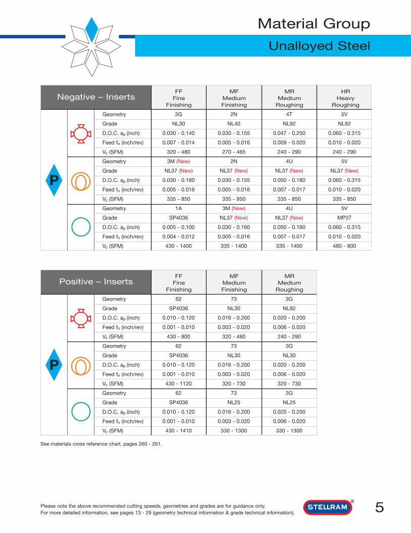
Material Group
Unalloyed Steel
Please note the above recommended cutting speeds, geometries and grades are for guidance only.For more detailed information, see pages 13 - 29 (geometry technical information & grade technical information).
Negative – Inserts
P
FF MF MR HRFine Medium Medium Heavy
Finishing Finishing Roughing Roughing
Geometry
Grade
D.O.C. ap (inch)
Feed fn (inch/rev)
Vc (SFM)
Geometry
Grade
D.O.C. ap (inch)
Feed fn (inch/rev)
Vc (SFM)
Geometry
Grade
D.O.C. ap (inch)
Feed fn (inch/rev)
Vc (SFM)
3G 2N 4T 5V
NL30 NL40 NL92 NL92
0.030 - 0.140 0.030 - 0.155 0.047 - 0.250 0.060 - 0.315
0.007 - 0.014 0.005 - 0.016 0.009 - 0.020 0.010 - 0.020
320 - 480 270 - 465 240 - 290 240 - 290
3M (New) 2N 4U 5V
NL37 (New) NL37 (New) NL37 (New) NL37 (New)
0.030 - 0.160 0.030 - 0.155 0.050 - 0.180 0.060 - 0.315
0.005 - 0.016 0.005 - 0.016 0.007 - 0.017 0.010 - 0.020
335 - 850 335 - 850 335 - 850 335 - 850
1A 3M (New) 4U 5V
SP4036 NL37 (New) NL37 (New) MP37
0.005 - 0.100 0.030 - 0.160 0.050 - 0.180 0.060 - 0.315
0.004 - 0.012 0.005 - 0.016 0.007 - 0.017 0.010 - 0.020
430 - 1400 335 - 1400 335 - 1400 480 - 800
Positive – Inserts
P
FF MF MRFine Medium Medium
Finishing Finishing Roughing
Geometry
Grade
D.O.C. ap (inch)
Feed fn (inch/rev)
Vc (SFM)
Geometry
Grade
D.O.C. ap (inch)
Feed fn (inch/rev)
Vc (SFM)
Geometry
Grade
D.O.C. ap (inch)
Feed fn (inch/rev)
Vc (SFM)
62 73 3G
SP4036 NL30 NL92
0.010 - 0.120 0.016 - 0.200 0.020 - 0.200
0.001 - 0.010 0.003 - 0.020 0.006 - 0.020
430 - 800 320 - 480 240 - 290
62 73 3G
SP4036 NL30 NL30
0.010 - 0.120 0.016 - 0.200 0.020 - 0.200
0.001 - 0.010 0.003 - 0.020 0.006 - 0.020
430 - 1120 320 - 730 320 - 730
62 73 3G
SP4036 NL25 NL25
0.010 - 0.120 0.016 - 0.200 0.020 - 0.200
0.001 - 0.010 0.003 - 0.020 0.006 - 0.020
430 - 1410 330 - 1300 330 - 1300
See materials cross reference chart, pages 260 - 261.
6
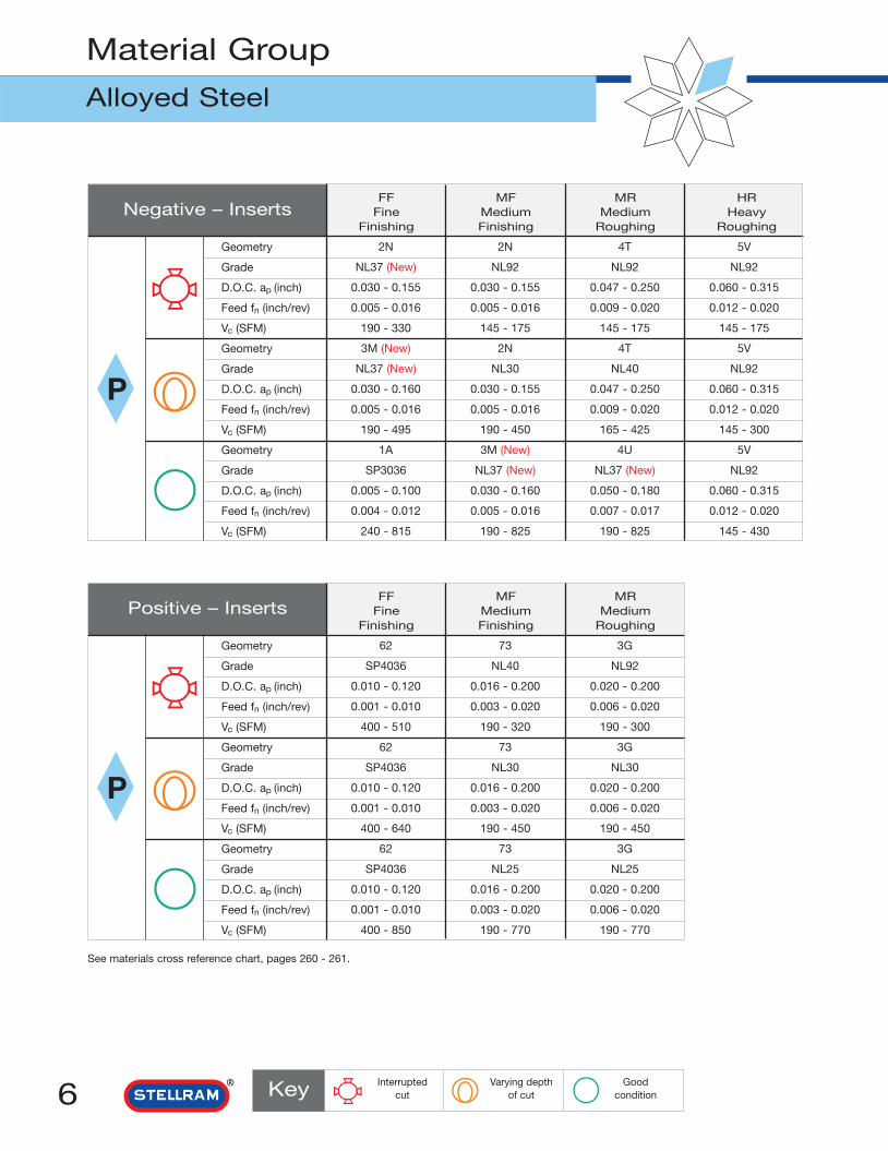
Material Group
Alloyed Steel
Key Goodcondition
Interruptedcut
Varying depthof cut
Negative – Inserts
P
FF MF MR HRFine Medium Medium Heavy
Finishing Finishing Roughing Roughing
Geometry
Grade
D.O.C. ap (inch)
Feed fn (inch/rev)
Vc (SFM)
Geometry
Grade
D.O.C. ap (inch)
Feed fn (inch/rev)
Vc (SFM)
Geometry
Grade
D.O.C. ap (inch)
Feed fn (inch/rev)
Vc (SFM)
2N 2N 4T 5V
NL37 (New) NL92 NL92 NL92
0.030 - 0.155 0.030 - 0.155 0.047 - 0.250 0.060 - 0.315
0.005 - 0.016 0.005 - 0.016 0.009 - 0.020 0.012 - 0.020
190 - 330 145 - 175 145 - 175 145 - 175
3M (New) 2N 4T 5V
NL37 (New) NL30 NL40 NL92
0.030 - 0.160 0.030 - 0.155 0.047 - 0.250 0.060 - 0.315
0.005 - 0.016 0.005 - 0.016 0.009 - 0.020 0.012 - 0.020
190 - 495 190 - 450 165 - 425 145 - 300
1A 3M (New) 4U 5V
SP3036 NL37 (New) NL37 (New) NL92
0.005 - 0.100 0.030 - 0.160 0.050 - 0.180 0.060 - 0.315
0.004 - 0.012 0.005 - 0.016 0.007 - 0.017 0.012 - 0.020
240 - 815 190 - 825 190 - 825 145 - 430
Positive – Inserts
P
FF MF MRFine Medium Medium
Finishing Finishing Roughing
Geometry
Grade
D.O.C. ap (inch)
Feed fn (inch/rev)
Vc (SFM)
Geometry
Grade
D.O.C. ap (inch)
Feed fn (inch/rev)
Vc (SFM)
Geometry
Grade
D.O.C. ap (inch)
Feed fn (inch/rev)
Vc (SFM)
62 73 3G
SP4036 NL40 NL92
0.010 - 0.120 0.016 - 0.200 0.020 - 0.200
0.001 - 0.010 0.003 - 0.020 0.006 - 0.020
400 - 510 190 - 320 190 - 300
62 73 3G
SP4036 NL30 NL30
0.010 - 0.120 0.016 - 0.200 0.020 - 0.200
0.001 - 0.010 0.003 - 0.020 0.006 - 0.020
400 - 640 190 - 450 190 - 450
62 73 3G
SP4036 NL25 NL25
0.010 - 0.120 0.016 - 0.200 0.020 - 0.200
0.001 - 0.010 0.003 - 0.020 0.006 - 0.020
400 - 850 190 - 770 190 - 770
See materials cross reference chart, pages 260 - 261.
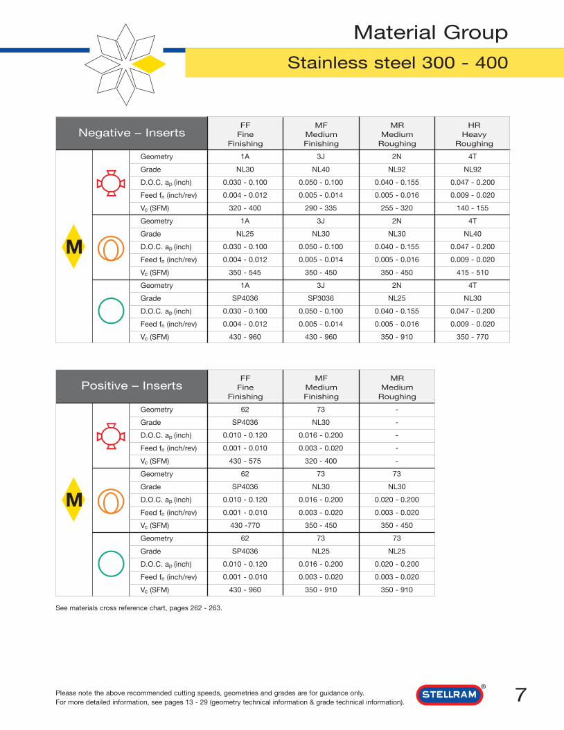
7Please note the above recommended cutting speeds, geometries and grades are for guidance only.For more detailed information, see pages 13 - 29 (geometry technical information & grade technical information).
Material Group
Stainless steel 300 - 400
Negative – Inserts
M
FF MF MR HRFine Medium Medium Heavy
Finishing Finishing Roughing Roughing
Geometry
Grade
D.O.C. ap (inch)
Feed fn (inch/rev)
Vc (SFM)
Geometry
Grade
D.O.C. ap (inch)
Feed fn (inch/rev)
Vc (SFM)
Geometry
Grade
D.O.C. ap (inch)
Feed fn (inch/rev)
Vc (SFM)
1A 3J 2N 4T
NL30 NL40 NL92 NL92
0.030 - 0.100 0.050 - 0.100 0.040 - 0.155 0.047 - 0.200
0.004 - 0.012 0.005 - 0.014 0.005 - 0.016 0.009 - 0.020
320 - 400 290 - 335 255 - 320 140 - 155
1A 3J 2N 4T
NL25 NL30 NL30 NL40
0.030 - 0.100 0.050 - 0.100 0.040 - 0.155 0.047 - 0.200
0.004 - 0.012 0.005 - 0.014 0.005 - 0.016 0.009 - 0.020
350 - 545 350 - 450 350 - 450 415 - 510
1A 3J 2N 4T
SP4036 SP3036 NL25 NL30
0.030 - 0.100 0.050 - 0.100 0.040 - 0.155 0.047 - 0.200
0.004 - 0.012 0.005 - 0.014 0.005 - 0.016 0.009 - 0.020
430 - 960 430 - 960 350 - 910 350 - 770
Positive – Inserts
M
FF MF MRFine Medium Medium
Finishing Finishing Roughing
Geometry
Grade
D.O.C. ap (inch)
Feed fn (inch/rev)
Vc (SFM)
Geometry
Grade
D.O.C. ap (inch)
Feed fn (inch/rev)
Vc (SFM)
Geometry
Grade
D.O.C. ap (inch)
Feed fn (inch/rev)
Vc (SFM)
62 73 -
SP4036 NL30 -
0.010 - 0.120 0.016 - 0.200 -
0.001 - 0.010 0.003 - 0.020 -
430 - 575 320 - 400 -
62 73 73
SP4036 NL30 NL30
0.010 - 0.120 0.016 - 0.200 0.020 - 0.200
0.001 - 0.010 0.003 - 0.020 0.003 - 0.020
430 -770 350 - 450 350 - 450
62 73 73
SP4036 NL25 NL25
0.010 - 0.120 0.016 - 0.200 0.020 - 0.200
0.001 - 0.010 0.003 - 0.020 0.003 - 0.020
430 - 960 350 - 910 350 - 910
See materials cross reference chart, pages 262 - 263.

8
Material Group
Stainless Steel PH
Key Goodcondition
Interruptedcut
Varying depthof cut
Negative – Inserts
M
FF MF MR HRFine Medium Medium Heavy
Finishing Finishing Roughing Roughing
Geometry
Grade
D.O.C. ap (inch)
Feed fn (inch/rev)
Vc (SFM)
Geometry
Grade
D.O.C. ap (inch)
Feed fn (inch/rev)
Vc (SFM)
Geometry
Grade
D.O.C. ap (inch)
Feed fn (inch/rev)
Vc (SFM)
2N 3J 2N 4M
NL30 NL40 NL40 NL92
0.040 - 0.240 0.047 - 0.100 0.040 - 0.155 0.047 - 0.275
0.008 - 0.016 0.005 - 0.014 0.005 - 0.016 0.012 - 0.020
185 - 215 160 - 190 160 - 190 130 - 160
3F 91 2N 4M
SP3064 SP3064 NL30 NL30
0.040 - 0.120 0.050 - 0.230 0.040 - 0.155 0.047 - 0.275
0.008 - 0.014 0.006 - 0.015 0.005 - 0.016 0.012 - 0.020
240 - 300 240 - 300 160 - 255 190 - 240
3F 91 2N 4M
SP4064 SP0864 SP0864 NL25
0.040 - 0.120 0.050 - 0.230 0.040 - 0.240 0.047 - 0.275
0.008 - 0.014 0.006 - 0.015 0.008 - 0.016 0.012 - 0.020
250 - 535 250 - 535 250 - 535 240 - 465
Positive – Inserts
M
FF MF MRFine Medium Medium
Finishing Finishing Roughing
Geometry
Grade
D.O.C. ap (inch)
Feed fn (inch/rev)
Vc (SFM)
Geometry
Grade
D.O.C. ap (inch)
Feed fn (inch/rev)
Vc (SFM)
Geometry
Grade
D.O.C. ap (inch)
Feed fn (inch/rev)
Vc (SFM)
62 73 -
SP4036 NL92 -
0.010 - 0.120 0.020 - 0.200 -
0.001 - 0.010 0.003 - 0.020 -
240 - 200 130 -225 -
62 73 -
SP4036 SFZ -
0.010 - 0.120 0.020 - 0.200 -
0.001 - 0.010 0.003 - 0.020 -
240 - 305 160 - 270 -
62 73 -
SP4036 NL25 -
0.010 - 0.120 0.020 - 0.200 -
0.001 - 0.010 0.003 - 0.020 -
240 - 510 190 - 465 -
See materials cross reference chart, pages 262 - 263.

9
Material Group
Cast Iron
Please note the above recommended cutting speeds, geometries and grades are for guidance only.For more detailed information, see pages 13 - 29 (geometry technical information & grade technical information).
Negative – Inserts
K
FF MF MR HRFine Medium Medium Heavy
Finishing Finishing Roughing Roughing
Geometry
Grade
D.O.C. ap (inch)
Feed fn (inch/rev)
Vc (SFM)
Geometry
Grade
D.O.C. ap (inch)
Feed fn (inch/rev)
Vc (SFM)
Geometry
Grade
D.O.C. ap (inch)
Feed fn (inch/rev)
Vc (SFM)
4U 4U 4T FLAT
SC1519 SC1519 MP37 MP37
0.020 - 0.160 0.020 - 0.160 0.047 - 0.255 0.050 - 0.235
0.004 - 0.016 0.004 - 0.016 0.009 - 0.020 0.012 - 0.025
400 - 625 400 - 625 480 - 575 480 - 575
4U 4U 4T FLAT
SC1519 SC1519 MP37 SC1519
0.020 - 0.160 0.020 - 0.160 0.047 - 0.255 0.050 - 0.235
0.004 - 0.016 0.004 - 0.016 0.009 - 0.020 0.012 - 0.025
400 - 625 400 - 625 290 - 640 400 - 945
4U 4U 4T FLAT
SC1519 SC1519 NL25 SC1519
0.020 - 0.160 0.020 - 0.160 0.047 - 0.255 0.050 - 0.235
0.004 - 0.016 0.004 - 0.016 0.009 - 0.020 0.012 - 0.025
400 - 625 400 - 625 290 - 1070 400 - 1570
Positive – Inserts
K
FF MF MRFine Medium Medium
Finishing Finishing Roughing
Geometry
Grade
D.O.C. ap (inch)
Feed fn (inch/rev)
Vc (SFM)
Geometry
Grade
D.O.C. ap (inch)
Feed fn (inch/rev)
Vc (SFM)
Geometry
Grade
D.O.C. ap (inch)
Feed fn (inch/rev)
Vc (SFM)
- - -
- - -
- - -
- - -
- - -
62 T 3G
GH2 GH1 MP37
0.010 - 0.120 0.040 - 0.235 0.020 - 0.160
0.001 - 0.010 0.008 - 0.020 0.004 - 0.014
305 - 400 225 - 510 500 - 650
62 T 3G
GH2 GH1 MP37
0.010 - 0.120 0.040 - 0.235 0.020 - 0.160
0.001 - 0.010 0.008 - 0.020 0.004 - 0.014
305 - 560 225 - 720 500 - 800
See materials cross reference chart, pages 264 - 265.

10
Material Group
Aluminum & Alloys
Key Goodcondition
Interruptedcut
Varying depthof cut
Negative – Inserts
N
FF MF MR HRFine Medium Medium Heavy
Finishing Finishing Roughing Roughing
Geometry
Grade
D.O.C. ap (inch)
Feed fn (inch/rev)
Vc (SFM)
Geometry
Grade
D.O.C. ap (inch)
Feed fn (inch/rev)
Vc (SFM)
Geometry
Grade
D.O.C. ap (inch)
Feed fn (inch/rev)
Vc (SFM)
- - - -
- - - -
- - - -
- - - -
- - - -
- 3F 3F -
- SP0864 SP0864 -
- 0.040 - 0.120 0.040 - 0.120 -
- 0.008 - 0.014 0.008 - 0.014 -
- 1170 - 1870 1170 - 1870 -
- 3F 3F -
- SP0864 SP0864 -
- 0.040 - 0.120 0.040 - 0.120 -
- 0.008 - 0.014 0.008 - 0.014 -
- 1170 - 3400 1170 - 3400 -
Positive – Inserts
N
FF MF MRFine Medium Medium
Finishing Finishing Roughing
Geometry
Grade
D.O.C. ap (inch)
Feed fn (inch/rev)
Vc (SFM)
Geometry
Grade
D.O.C. ap (inch)
Feed fn (inch/rev)
Vc (SFM)
Geometry
Grade
D.O.C. ap (inch)
Feed fn (inch/rev)
Vc (SFM)
- 64 64
- GH1 GH1
- 0.080 - 0.235 0.080 - 0.235
- 0.014 - 0.025 0.014 - 0.025
- 590 - 1070 590 - 1070
15 64 64
GH1 GH1 GH1
0.030 - 0.080 0.080 - 0.235 0.080 - 0.235
0.002 - 0.008 0.014 - 0.025 0.014 - 0.025
590 - 1570 590 - 1570 590 - 1570
15 64 64
GH1 GH1 GH1
0.030 - 0.080 0.080 - 0.235 0.080 - 0.235
0.002 - 0.008 0.014 - 0.025 0.014 - 0.025
590 - 2625 590 - 2625 590 - 2625
See materials cross reference chart, pages 264 - 265.

11
Material Group
High Temperature Alloys
Please note the above recommended cutting speeds, geometries and grades are for guidance only.For more detailed information, see pages 13 - 29 (geometry technical information & grade technical information).
Negative – Inserts
S
FF MF MR HRFine Medium Medium Heavy
Finishing Finishing Roughing Roughing
Geometry
Grade
D.O.C. ap (inch)
Feed fn (inch/rev)
Vc (SFM)
Geometry
Grade
D.O.C. ap (inch)
Feed fn (inch/rev)
Vc (SFM)
Geometry
Grade
D.O.C. ap (inch)
Feed fn (inch/rev)
Vc (SFM)
2N 91 2N 4M
SP0864 SP3064 NL92 NL30
0.040 - 0.240 0.050 - 0.230 0.040 - 0.240 0.040 - 0.200
0.008 - 0.016 0.006 - 0.015 0.008 - 0.016 0.012 - 0.020
80 - 120 85 - 120 50 - 100 65 - 100
3F 91 2N 4M
SP3064 SP3064 SP0864 NL30
0.040 - 0.120 0.050 - 0.230 0.040 - 0.240 0.040 - 0.200
0.005 - 0.014 0.006 - 0.015 0.008 - 0.016 0.012 - 0.020
80 - 170 80 - 170 90 - 120 65 - 140
1A 3F 2N 4M
SP4036 SP0864 SP0864 NL30
0.005 - 0.100 0.040 - 0.120 0.040 - 0.240 0.040 - 0.200
0.004 - 0.012 0.005 - 0.014 0.008 - 0.016 0.012 - 0.020
80 - 290 80 - 295 90 - 295 65 - 225
Positive – Inserts
S
FF MF MRFine Medium Medium
Finishing Finishing Roughing
Geometry
Grade
D.O.C. ap (inch)
Feed fn (inch/rev)
Vc (SFM)
Geometry
Grade
D.O.C. ap (inch)
Feed fn (inch/rev)
Vc (SFM)
Geometry
Grade
D.O.C. ap (inch)
Feed fn (inch/rev)
Vc (SFM)
62 - -
GH2 - -
0.010 - 0.120 - -
0.001 - 0.010 - -
50 - 95 - -
62 M 73
SP4036 GH1 SFZ
0.010 - 0.120 0.020 - 0.155 0.020 - 0.200
0.001 - 0.010 0.004 - 0.008 0.003 - 0.020
80 - 190 65 - 130 50 - 110
62 M 73
SP4036 GH1 SFZ
0.010 - 0.120 0.020 - 0.155 0.020 - 0.200
0.001 - 0.010 0.004 - 0.008 0.003 - 0.020
80 - 290 65 - 255 50 - 175
See materials cross reference chart, pages 266 - 273.

12
Material Group
Hard Materials
Key Goodcondition
Interruptedcut
Varying depthof cut
Negative – Inserts
H
FF MF MR HRFine Medium Medium Heavy
Finishing Finishing Roughing Roughing
Geometry
Grade
D.O.C. ap (inch)
Feed fn (inch/rev)
Vc (SFM)
Geometry
Grade
D.O.C. ap (inch)
Feed fn (inch/rev)
Vc (SFM)
Geometry
Grade
D.O.C. ap (inch)
Feed fn (inch/rev)
Vc (SFM)
4U 4T 4T -
NL37 (New) NL37 (New) NL37 (New) -
0.050 - 0.180 0.047 - 0.250 0.047 - 0.250 -
0.007 - 0.017 0.008 - 0.016 0.008 - 0.016 -
100 - 135 100 - 135 100 - 135 -
2N 4U 4U -
NL37 (New) NL37 (New) NL37 (New) -
0.040 - 0.160 0.050 - 0.180 0.050 - 0.180 -
0.005 - 0.016 0.007 - 0.017 0.007 - 0.017 -
150 - 175 150 - 175 150 - 175 -
1A 2N 2N -
SP4036 SP0864 SP0864 -
0.005 - 0.100 0.030 - 0.155 0.030 - 0.155 -
0.004 - 0.012 0.005 - 0.016 0.005 - 0.016 -
155 - 420 200 - 440 200 - 440 -
Positive – Inserts
H
FF MF MRFine Medium Medium
Finishing Finishing Roughing
Geometry
Grade
D.O.C. ap (inch)
Feed fn (inch/rev)
Vc (SFM)
Geometry
Grade
D.O.C. ap (inch)
Feed fn (inch/rev)
Vc (SFM)
Geometry
Grade
D.O.C. ap (inch)
Feed fn (inch/rev)
Vc (SFM)
- - -
- - -
- - -
- - -
- - -
- - -
*SA7402 *SA7402 -
- - -
- - -
65 - 280 65 - 260 -
- - -
*SA7402 *SA7402 -
- - -
- - -
65 - 280 65 - 260 -
* For the SA grade information, please refer to pages 32 - 33 and the Stellram Ceramic Catalog.
Chip Control ChartCNMG120408E-1A
fn (in/rev) Feed
7,50mm
6,50mm
5,50mm
4,50mm
3,50mm
2,50mm
1,50mm
0,50mm
0,10mm 0,20mm 0,30mm 0,40mm 0,50mm 0,60mm
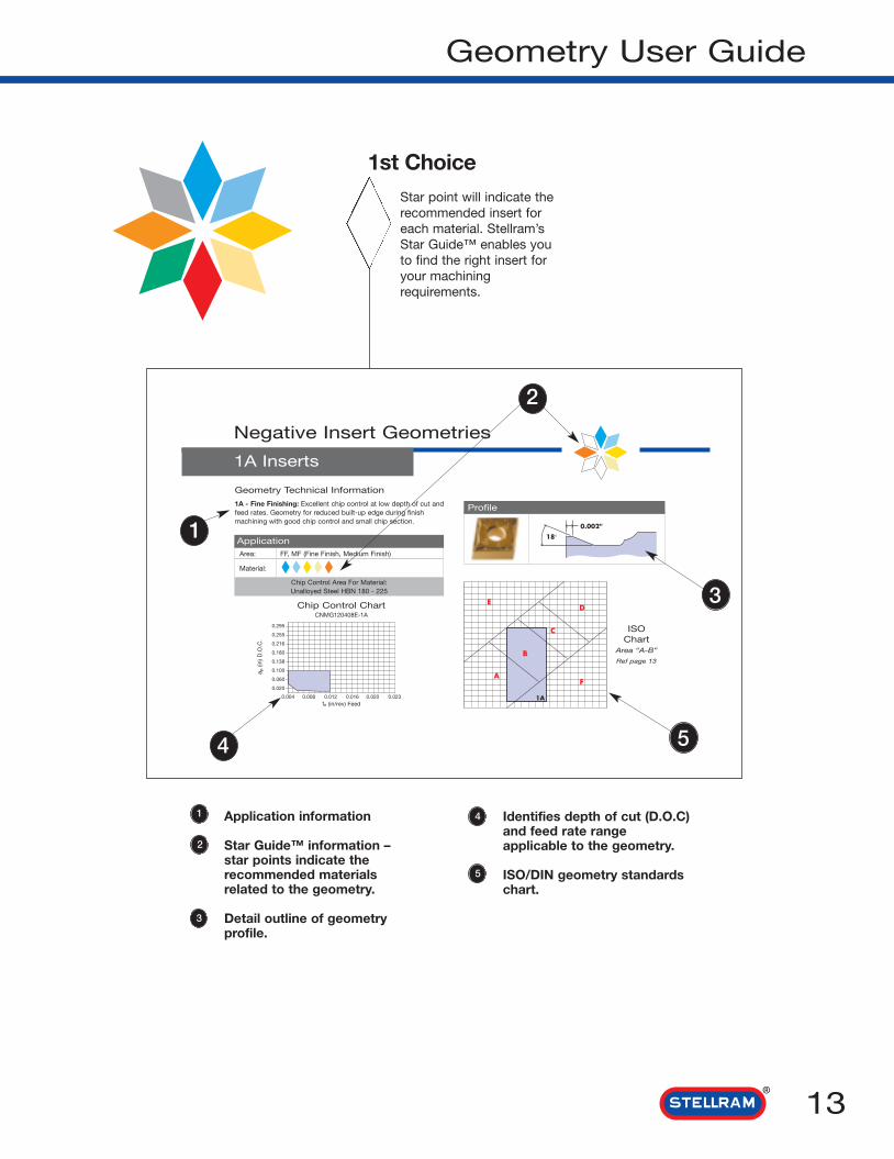
13
Geometry User Guide
1st ChoiceStar point will indicate therecommended insert foreach material. Stellram’sStar Guide™ enables youto find the right insert foryour machiningrequirements.
Application information
Star Guide™ information –star points indicate therecommended materialsrelated to the geometry.
Detail outline of geometryprofile.
2
1
3
Negative Insert Geometries
1A Inserts
Geometry Technical Information
1A - Fine Finishing: Excellent chip control at low depth of cut andfeed rates. Geometry for reduced built-up edge during finishmachining with good chip control and small chip section.
Profile
Chip Control Area For Material:Unalloyed Steel HBN 180 - 225
ApplicationArea: FF, MF (Fine Finish, Medium Finish)
Material:
1A
ED
B
C
FA
ISOChart
Area “A-B”
Ref page 13
5
2
1
Identifies depth of cut (D.O.C)and feed rate rangeapplicable to the geometry.
ISO/DIN geometry standardschart.
4
5
0.295
0.255
0.216
0.180
0.138
0.100
0.060
0.020
4
3
a p(in
) D.O
.C.
0.004 0.008 0.012 0.016 0.020 0.023

Geometry User Guide
The following pages show the above chart in conjunction with Stellram geometries. Thecharts show the ISO/DIN standard reference position relative to each geometry by defininga letter for each zone - A. B. C. D. E & F. These zones are represented by depth of cut (ap in) and a feed (fn in/rev) ranges. Each geometry has its own operating rangerepresented by the chip control area, or footprint. These zones classify the application areaof a given geometry.
fn in/rev Feed/Rev
Example of a geometry chip control area or footprint
The following are Stellram’sguideline classification for eachzone of ISO/DIN 10 910:
A Fine FinishingA/B FinishingB Medium FinishingB/C Light RoughingC Medium RoughingC/D Heavy Roughing
fn in/rev Feed/Rev
Real AreaTheoretical Area
ap (i
n) D
.O.C
ap (i
n) D
.O.C
14

15
Negative Insert Geometries
1A Inserts
2B Inserts
Geometry Technical Information
1A - Fine Finishing: Excellent chip control at low depth of cut andfeed rates. Geometry for reduced built-up edge during finishmachining with good chip control and small chip section.
Profile
Chip Control Area For Material:Unalloyed Steel HBN 180 - 225
ApplicationArea: FF, MF (Fine Finish, Medium Finish)
Material:
1A
ED
B
C
FA
ISOChart
Area “A-B”
Ref page 14
Geometry Technical Information
2B - Finishing: Positive cutting action for very light depths of cutand feeds. Positive rake provides lower cutting pressures allowingincreased tool life.
Profile
Chip Control Area For Material:Alloyed Steel HBN 230 - 340
ApplicationArea: MF (Medium Finish)
Material:
2B
ED
B
C
FA
ISOChart
Area “B”
Ref page 14
Chip Control ChartCNMG432A-1A
a p(in
) D.O
.C.
7,50mm
6,50mm
5,50mm
4,50mm
3,50mm
2,50mm
1,50mm
0,50mm
0,10mm 0,20mm 0,30mm 0,40mm 0,50mm 0,60mm
0.2950.2550.2160.1800.1380.1000.0600.020
0.004 0.008 0.012 0.016 0.020 0.023fn (in/rev) Feed
Chip Control ChartCNMG432A-2B
a p(in
) D.O
.C.
7,50mm
6,50mm
5,50mm
4,50mm
3,50mm
2,50mm
1,50mm
0,50mm
0,10mm 0,20mm 0,30mm 0,40mm 0,50mm 0,60mm
0.2950.2550.2160.1800.1380.1000.0600.020
0.004 0.008 0.012 0.016 0.020 0.023
fn (in/rev) Feed
N
Material Designations
High Temp. Alloys
Hard Materials
Cast Irons
Aluminum & Alloys
Stainless Steels
PH Stainless
Unalloyed Steels
Alloyed Steels
Star Guide Key to Recommended Inserts
P M K S
HMP

Chip Control ChartCNGP432-3F
a p(in
) D.O
.C.
7,50mm
6,50mm
5,50mm
4,50mm
3,50mm
2,50mm
1,50mm
0,50mm
0,10mm 0,20mm 0,30mm 0,40mm 0,50mm 0,60mm
16
Negative Insert Geometries
2N Inserts
3F Inserts
Geometry Technical Information3F - Finishing to Light Roughing: 3F geometry has peripheryground edges to maintain accurate profiles and insert indexabillty.A sharp edge treatment reduces built-up edge and improvessurface finishes.
Profile
Chip Control Area For Material:Stainless Steel HBN 120 - 180
ApplicationArea: MF, MR (Medium Finish, Medium Roughing)
Material:
3F
ED
B
C
FA
ISOChart
Area “B-C”
Ref page 14
10°
Chip Control ChartCNMG432A-2N
a p(in
) D.O
.C.
7,50mm
6,50mm
5,50mm
4,50mm
3,50mm
2,50mm
1,50mm
0,50mm
0,10mm 0,20mm 0,30mm 0,40mm 0,50mm 0,60mm
Geometry Technical Information2N - Light to Medium Roughing: Positive rake angle provides apositive cutting action and reduced cutting pressure, this makes2N a good starting geometry for a wide range of application /materials.
Profile
Chip Control Area For Material:Alloyed Steel HBN 260 - 340
ApplicationArea: MF, MR (Medium Finish, Medium Roughing)
Material:
2N
ED
B
C
FA
ISOChart
Area “B-C”
Ref page 14
10°
0,15
0.2950.2550.2160.1800.1380.1000.0600.020
0.004 0.008 0.012 0.016 0.020 0.023
fn (in/rev) Feed
0.006"
0.2950.2550.2160.1800.1380.1000.0600.020
0.004 0.008 0.012 0.016 0.020 0.023fn (in/rev) Feed
N
Material Designations
High Temp. Alloys
Hard Materials
Cast Irons
Aluminum & Alloys
Stainless Steels
PH Stainless
Unalloyed Steels
Alloyed Steels
Star Guide Key to Recommended Inserts
P M K S
HMP
17
Negative Insert Geometries
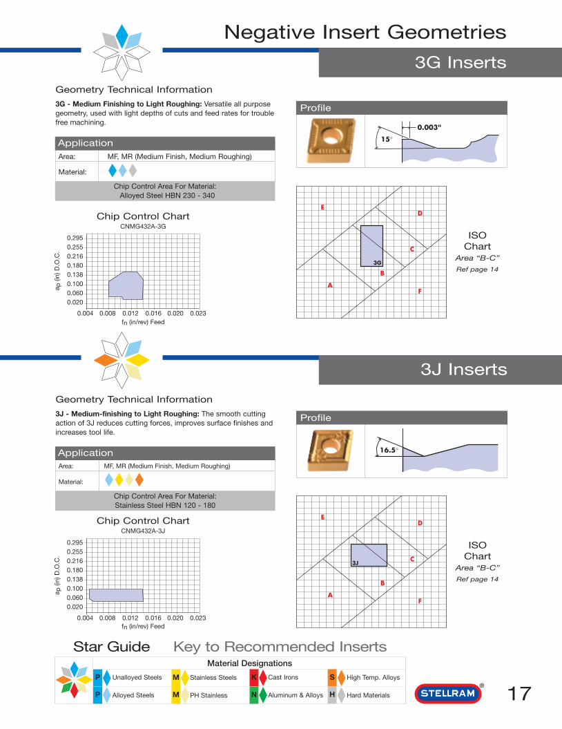
3G Inserts
Geometry Technical Information
3J - Medium-finishing to Light Roughing: The smooth cuttingaction of 3J reduces cutting forces, improves surface finishes andincreases tool life.
Profile
Chip Control Area For Material:Stainless Steel HBN 120 - 180
ApplicationArea: MF, MR (Medium Finish, Medium Roughing)
Material:
3J
ED
B
C
FA
ISOChart
Area “B-C”
Ref page 14
3J Inserts
16.5°
Chip Control ChartCNMG432A-3G
a p(in
) D.O
.C.
7,50mm
6,50mm
5,50mm
4,50mm
3,50mm
2,50mm
1,50mm
0,50mm
0,10mm 0,20mm 0,30mm 0,40mm 0,50mm 0,60mm
Geometry Technical Information
3G - Medium Finishing to Light Roughing: Versatile all purposegeometry, used with light depths of cuts and feed rates for troublefree machining.
Profile
Chip Control Area For Material:Alloyed Steel HBN 230 - 340
ApplicationArea: MF, MR (Medium Finish, Medium Roughing)
Material:
3G
ED
B
C
FA
ISOChart
Area “B-C”
Ref page 14
15°
0.003"
0.2950.2550.2160.1800.1380.1000.0600.020
0.004 0.008 0.012 0.016 0.020 0.023fn (in/rev) Feed
Chip Control ChartCNMG432A-3J
a p(in
) D.O
.C.
7,50mm
6,50mm
5,50mm
4,50mm
3,50mm
2,50mm
1,50mm
0,50mm
0,10mm 0,20mm 0,30mm 0,40mm 0,50mm 0,60mm
0.2950.2550.2160.1800.1380.1000.0600.020
0.004 0.008 0.012 0.016 0.020 0.023fn (in/rev) Feed
N
Material Designations
High Temp. Alloys
Hard Materials
Cast Irons
Aluminum & Alloys
Stainless Steels
PH Stainless
Unalloyed Steels
Alloyed Steels
Star Guide Key to Recommended Inserts
P M K S
HMP

18
Negative Insert Geometries
3M Inserts
4M Inserts
Geometry Technical Information3M - Semi Finishing to Light Roughing: All Purpose geometrysuitable for precision forged and cast components, offeringexcellent chip control at varying depths of cut.
Profile
Chip Control Area For Material:Steel 4140 267HBN
Application
Area: MF, MR (Medium Finish, Medium Roughing)
Material:
3M
ED
B
C
FA
ISOChart
Area “B-C”
Ref page 14
Chip Control ChartCNMG432A-3M
a p(in
) D.O
.C.
7,50mm
6,50mm
5,50mm
4,50mm
3,50mm
2,50mm
1,50mm
0,50mm
0,10mm 0,20mm 0,30mm 0,40mm 0,50mm 0,60mm
0,050
16.5º
Geometry Technical Information
4M - Medium to Heavy Roughing: Single sided inserts for stabilityand strength with a soft cutting action, which allows for high feedrates.
Profile
Chip Control Area For Material:Alloyed Steel HBN 230 - 340
ApplicationArea: MR, HR (Medium Roughing, Heavy Roughing)
Material:
4M
ED
B
C
FA
ISOChart
Area “C-D”
Ref page 14
7,50mm
6,50mm
5,50mm
4,50mm
3,50mm
2,50mm
1,50mm
0,50mm
0,10mm 0,20mm 0,30mm 0,40mm 0,50mm 0,60mm
0.058"
0.2950.2550.2160.1800.1380.1000.0600.020
0.004 0.008 0.012 0.016 0.020 0.023fn (in/rev) Feed
0.2950.2550.2160.1800.1380.1000.0600.020
0.004 0.008 0.012 0.016 0.020 0.023
Chip Control ChartCNMG432A-4M
a p(in
) D.O
.C.
fn (in/rev) Feed
N
Material Designations
High Temp. Alloys
Hard Materials
Cast Irons
Aluminum & Alloys
Stainless Steels
PH Stainless
Unalloyed Steels
Alloyed Steels
Star Guide Key to Recommended Inserts
P M K S
HMP

19
Geometry Technical Information
4T - General Purpose Roughing: New designed version of4T with improved surface contact, a good all round negativeroughing geometry for a wide range of application.
Profile
Chip Control Area For Material:Alloyed Steel HBN 230 - 340
ApplicationArea: MF, MR, HR (Medium Finish, Medium Roughing, Heavy Roughing)
Material:
4T
ED
B C
FA
ISOChart
Area “B-C-D”
Ref page 14
Negative Insert Geometries
4T Inserts
Geometry Technical Information
4U - Medium and Roughing: This geometry is ideal from roughingapplications, excellent chip control with low cutting pressure toextend tooling life in steels alloys and spheroidal irons.
Profile
Chip Control Area For Material:Ductile Iron HBN 170
ApplicationArea: FF, MF, MR (Fine Finish, Medium Finish, Medium Roughing)
Material:
4U
ED
B
C
FA
ISOChart
Area “B-C”
Ref page 14
10°
4U Inserts
Chip Control ChartCNMG432A-4T
a p(in
) D.O
.C.
7,50mm
6,50mm
5,50mm
4,50mm
3,50mm
2,50mm
1,50mm
0,50mm
0,10mm 0,20mm 0,30mm 0,40mm 0,50mm 0,60mm
Chip Control ChartCNMG432A-4U
a p(in
) D.O
.C.
7,50mm
6,50mm
5,50mm
4,50mm
3,50mm
2,50mm
1,50mm
0,50mm
0,10mm 0,20mm 0,30mm 0,40mm 0,50mm 0,60mm
0.2950.2550.2160.1800.1380.1000.0600.020
0.004 0.008 0.012 0.016 0.020 0.023
0.2950.2550.2160.1800.1380.1000.0600.020
0.004 0.008 0.012 0.016 0.020 0.023Feed fn (mm/rev)
Feed fn (mm/rev)
N
Material Designations
High Temp. Alloys
Hard Materials
Cast Irons
Aluminum & Alloys
Stainless Steels
PH Stainless
Unalloyed Steels
Alloyed Steels
Star Guide Key to Recommended Inserts
P M K S
HMP

20
Negative Insert Geometries
5V Inserts
91 Inserts
Geometry Technical Information
5V - Heavy Roughing: Negative cutting action with extra edgesupport for superb roughing performance with very heavy feedsand depths of cut.
Profile
Chip Control Area For Material:Alloyed Steel HBN 260 - 340
ApplicationArea: MR, HR (Medium Roughing, Heavy Roughing)
Material:
5V
ED
B
C
FA
ISOChart
Area “C-D”
Ref page 14
Chip Control ChartCNMG432A-5V
a p(in
) D.O
.C.
7,50mm
6,50mm
5,50mm
4,50mm
3,50mm
2,50mm
1,50mm
0,50mm
0,10mm 0,20mm 0,30mm 0,40mm 0,50mm 0,60mm
0.2950.2550.2160.1800.1380.1000.0600.020
0.004 0.008 0.012 0.016 0.020 0.023fn (in/rev) Feed
Geometry Technical Information
91 - Finishing to Light Roughing: Open, positive geometryproduces excellent chip control with low cutting forces in hightemperture alloys like titanium and inconel.
Profile
Chip Control Area For Material:Titanium Ti-6AI-4V
ApplicationArea: MF, MR (Medium Finish, Medium Roughing)
Material:
91
ED
B
C
FA
ISOChart
Area “B-C”
Ref page 14
Chip Control ChartCNMG432A-91
a p(in
) D.O
.C.
7,50mm
6,50mm
5,50mm
4,50mm
3,50mm
2,50mm
1,50mm
0,50mm
0,10mm 0,20mm 0,30mm 0,40mm 0,50mm 0,60mm
0.2950.2550.2160.1800.1380.1000.0600.020
0.004 0.008 0.012 0.016 0.020 0.023fn (in/rev) Feed
0.002"
N
Material Designations
High Temp. Alloys
Hard Materials
Cast Irons
Aluminum & Alloys
Stainless Steels
PH Stainless
Unalloyed Steels
Alloyed Steels
Star Guide Key to Recommended Inserts
P M K S
HMP

21
Positive Insert Geometries
15 Inserts
Geometry Technical Information
15 - Medium-finishing: Sharp edge and ground geometry for finishmachining at light depths of cut and feeds. Designed to reducevibration.
Profile
ApplicationArea: FF, MF (Fine Finish, Medium Finish)
Material:
15
ED
BC
FA
ISOChart
Area “B”
Ref page 14
Geometry Technical Information
61 - Finishing: A sintered insert with pressed in chipbreakerprovides good chip control and surface finish.
Profile
ApplicationArea: FF, MF, MR (Fine Finish, Medium Finish, Medium Roughing)
Material:
61
ED
B
C
FA
ISOChart
Area “A-B”
Ref page 14
61 Inserts
Chip Control Area For Material:Aluminum <16% HBN 116
Chip Control Area For Material:Unalloyed Steel HBN 220 - 270
Chip Control ChartEPEX040404F-15
a p(in
) D.O
.C.
7,50mm
6,50mm
5,50mm
4,50mm
3,50mm
2,50mm
1,50mm
0,50mm
0,05mm 0,10mm 0,20mm 0,30mm 0,40mm
Chip Control ChartWPMT050304E-61
a p(in
) D.O
.C.
7,50mm
6,50mm
5,50mm
4,50mm
3,50mm
2,50mm
1,50mm
0,50mm
0,05mm 0,10mm 0,20mm 0,30mm 0,40mm
0.2950.2550.2160.1800.1380.1000.0600.020
0.002 0.004 0.008 0.012 0.016 0.020fn (in/rev) Feed
0.2950.2550.2160.1800.1380.1000.0600.020
0.002 0.004 0.008 0.012 0.016 0.020fn (in/rev) Feed
N
Material Designations
High Temp. Alloys
Hard Materials
Cast Irons
Aluminum & Alloys
Stainless Steels
PH Stainless
Unalloyed Steels
Alloyed Steels
Star Guide Key to Recommended Inserts
P M K S
HMP

22
Positive Insert Geometries
62 Inserts
Geometry Technical Information
62 - Finishing: A periphery ground geometry with optimizedchipbreaker for close tolerances and surface finishes.
Profile
ApplicationArea: FF, MF, MR (Fine Finish, Medium Finish, Medium Roughing)
Material:
62
ED
B
C
F
A
64 Inserts
ISOChart
Area “A-B”
Ref page 14
Geometry Technical Information
64 - Medium Roughing: A highly positive, periphery groundgeometry with a polished top rake for machining aluminum.
Profile
ApplicationArea: MR (Medium Roughing)
Material:
64
ED
BC
FA
ISOChart
Area “C-D”
Ref page 14
Chip Control Area For Material:Unalloyed Steel HBN 220 - 270
Chip Control Area For Material:Aluminum <16% HBN 116
Chip Control ChartEPGT060204E-62
a p(in
) D.O
.C.
7,50mm
6,50mm
5,50mm
4,50mm
3,50mm
2,50mm
1,50mm
0,50mm
0,05mm 0,10mm 0,20mm 0,30mm 0,40mm
Chip Control ChartDCGT11T308F-64
a p(in
) D.O
.C.
7,50mm
6,50mm
5,50mm
4,50mm
3,50mm
2,50mm
1,50mm
0,50mm
0,05mm 0,10mm 0,20mm 0,30mm 0,40mm 0,50mm 0,60mm
0.2950.2550.2160.1800.1380.1000.0600.020
0.002 0.004 0.008 0.012 0.016 0.020fn (in/rev) Feed
0.2950.2550.2160.1800.1380.1000.0600.020
0 0.002 0.004 0.008 0.012 0.016 0.020 0.024fn (in/rev) Feed
N
Material Designations
High Temp. Alloys
Hard Materials
Cast Irons
Aluminum & Alloys
Stainless Steels
PH Stainless
Unalloyed Steels
Alloyed Steels
Star Guide Key to Recommended Inserts
P M K S
HMP
23
Positive Insert Geometries
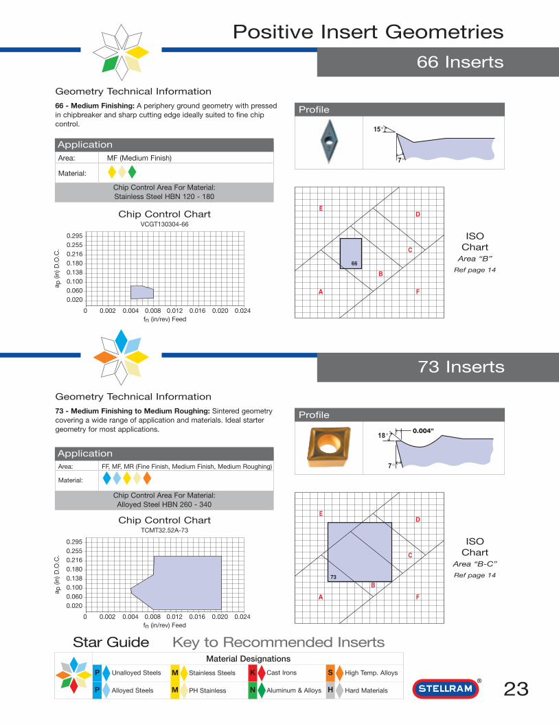
66 Inserts
Geometry Technical Information
66 - Medium Finishing: A periphery ground geometry with pressedin chipbreaker and sharp cutting edge ideally suited to fine chipcontrol.
ApplicationArea: MF (Medium Finish)
Material:
66
ED
B
C
FA
ISOChart
Area “B”
Ref page 14
Geometry Technical Information
73 - Medium Finishing to Medium Roughing: Sintered geometrycovering a wide range of application and materials. Ideal startergeometry for most applications.
Profile
ApplicationArea: FF, MF, MR (Fine Finish, Medium Finish, Medium Roughing)
Material:
73
ED
B
C
FA
ISOChart
Area “B-C”
Ref page 14
73 Inserts
Chip Control Area For Material:Stainless Steel HBN 120 - 180
Chip Control Area For Material:Alloyed Steel HBN 260 - 340
Profile
Chip Control ChartVCGT130304-66
a p(in
) D.O
.C.
7,50mm
6,50mm
5,50mm
4,50mm
3,50mm
2,50mm
1,50mm
0,50mm
0,05mm 0,10mm 0,20mm 0,30mm 0,40mm 0,50mm 0,60mm
Chip Control ChartTCMT32.52A-73
a p(in
) D.O
.C.
7,50mm
6,50mm
5,50mm
4,50mm
3,50mm
2,50mm
1,50mm
0,50mm
0,05mm 0,10mm 0,20mm 0,30mm 0,40mm 0,50mm 0,60mm
0.2950.2550.2160.1800.1380.1000.0600.020
0 0.002 0.004 0.008 0.012 0.016 0.020 0.024fn (in/rev) Feed
0.2950.2550.2160.1800.1380.1000.0600.020
0 0.002 0.004 0.008 0.012 0.016 0.020 0.024fn (in/rev) Feed
N
Material Designations
High Temp. Alloys
Hard Materials
Cast Irons
Aluminum & Alloys
Stainless Steels
PH Stainless
Unalloyed Steels
Alloyed Steels
Star Guide Key to Recommended Inserts
P M K S
HMP
24
Positive Insert Geometries
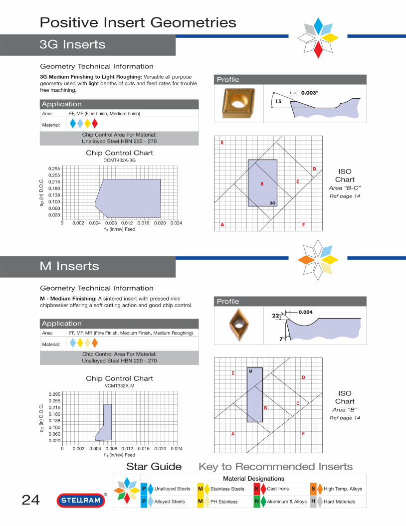
3G Inserts
Geometry Technical Information
3G Medium Finishing to Light Roughing: Versatile all purposegeometry used with light depths of cuts and feed rates for troublefree machining.
Profile
ApplicationArea: FF, MF (Fine finish, Medium finish)
Material:
E
A
C
D
B
3G
F
ISOChart
Area “B-C”
Ref page 14
M Inserts
Geometry Technical Information
M - Medium Finishing: A sintered insert with pressed minichipbreaker offering a soft cutting action and good chip control.
Profile
ApplicationArea: FF, MF, MR (Fine Finish, Medium Finish, Medium Roughing)
Material:
MED
BC
FA
ISOChart
Area “B”
Ref page 14
Chip Control Area For Material:Unalloyed Steel HBN 220 - 270
15°
0.003"
Chip Control Area For Material:Unalloyed Steel HBN 220 - 270
Chip Control ChartCCMT432A-3G
a p(in
) D.O
.C.
7,50mm
6,50mm
5,50mm
4,50mm
3,50mm
2,50mm
1,50mm
0,50mm
0,05mm 0,10mm 0,20mm 0,30mm 0,40mm 0,50mm 0,60mm
Chip Control ChartVCMT332A-M
a p(in
) D.O
.C.
7,50mm
6,50mm
5,50mm
4,50mm
3,50mm
2,50mm
1,50mm
0,50mm
0,05mm 0,10mm 0,20mm 0,30mm 0,40mm 0,50mm 0,60mm
0.2950.2550.2160.1800.1380.1000.0600.020
0 0.002 0.004 0.008 0.012 0.016 0.020 0.024fn (in/rev) Feed
0.2950.2550.2160.1800.1380.1000.0600.020
0 0.002 0.004 0.008 0.012 0.016 0.020 0.024fn (in/rev) Feed
N
Material Designations
High Temp. Alloys
Hard Materials
Cast Irons
Aluminum & Alloys
Stainless Steels
PH Stainless
Unalloyed Steels
Alloyed Steels
Star Guide Key to Recommended Inserts
P M K S
HMP

25
Positive Insert Geometries
T Inserts
X Inserts
Geometry Technical Information
X - Medium Finishing to Medium Roughing: Precision groundparallel chip groove available with a fully ground periphery or aspressed, and with a sharp or honed edge condition. This geometrycan machine a variety of materials in vibration sensitive operations. 15°
7°
0.008"
Profile
ApplicationArea: MF, MR (Medium Finish, Medium Roughing)
Material:
X
ED
B C
FA
ISOChart
Area “B-C”
Ref page 14
Geometry Technical Information
T - Medium Finishing to Medium Roughing: A utility geometrygiving a stable cutting action in demanding conditions.
Profile
ApplicationArea: MF, MR (Medium Finish, Medium Roughing)
Material:
T
ED
B C
FA
ISOChart
Area “B-C”
Ref page 14
Chip Control Area For Material:Unalloyed Steel HBN 220 - 270
Chip Control Area For Material:Aluminum <16% HBN 116
Chip Control ChartTCMT32.52A
a p(in
) D.O
.C.
7,50mm
6,50mm
5,50mm
4,50mm
3,50mm
2,50mm
1,50mm
0,50mm
0,05mm 0,10mm 0,20mm 0,30mm 0,40mm 0,50mm 0,60mm
Chip Control ChartECMX12T308EL-25
a p(in
) D.O
.C.
7,50mm
6,50mm
5,50mm
4,50mm
3,50mm
2,50mm
1,50mm
0,50mm
0,05mm 0,10mm 0,20mm 0,30mm 0,40mm 0,50mm 0,60mm
0.2950.2550.2160.1800.1380.1000.0600.020
0 0.002 0.004 0.008 0.012 0.016 0.020 0.024fn (in/rev) Feed
0.2950.2550.2160.1800.1380.1000.0600.020
0 0.002 0.004 0.008 0.012 0.016 0.020 0.024fn (in/rev) Feed
N
Material Designations
High Temp. Alloys
Hard Materials
Cast Irons
Aluminum & Alloys
Stainless Steels
PH Stainless
Unalloyed Steels
Alloyed Steels
Star Guide Key to Recommended Inserts
P M K S
HMP

26
Grade Descriptions
Grade NL25A wear resistant grade for semi-finishing and finishing on steels, stainless steelsand cast irons. Coating structure - CVD TiN - TiCN - Al2O3 - TiN.
Grade NL30A colbalt enriched grade for medium machining and roughing on steels,stainless steels and cast irons. Coating structure - CVD TiN - TiCN - Al2O3 - TiN.
Grade NL37 (New)Coated grade TiN-MT TiCN-TiN Al2O3 MT TiCN-TiN by CVD. Principally for
machining steels and alloy steels.The coating has excellent resistance to wear. The enriched substrate aids resistance to stock.
Grade NL40A colbalt enriched grade for medium machining and roughing primarily onstainless steels and exotic alloys. Coating structure - CVD TiN - TiCN - Al2O3 - TiN.
Grade NL92A tough grade with a high degree of edge security on steels and stainless steels. Coating structure - CVD TiN - TiCN - Al2O3 - TiN.
Grade SC1519First choice wear resistant grade for medium and finish machining of cast irons. Coating structure - CVD TiN - TiCN - Al2O3 - TiN.
Grade MP37A wear and heat resistant grade for machining steels, stainless steels andcast iron. Coating structure - CVD TiN - TiCN - Al2O3.

27
Grade Descriptions
Grade SP0864A wear resistant grade with micro-grain carbide substrate. Primarily for finishmachining of titanium and exotic alloys. Coating structure - PVD TiAlN.
Grade SP3036/SP3064A hard grade for light roughing and finishing operations at higher speeds.Principle application exotic alloys. Coating structure - PVD TiAlN.
Grade SP4036/SP4064A hard grade for light roughing and finishing operations with lower chipsections. Principle application stainless steels, exotic alloys and cast irons. Coating structure - PVD TiAlN.
Grade SFZA utility grade with micro-grain carbide substrate. For operations requiring asharp edge condition. Coating structure - PVD TiN.
Grade GH1 - UncoatedUncoated micro-grain for cast iron, hardened steels to 60 HRC and non ferrousalloys. Low cutting pressure at high speeds due to sharp cutting edges.
Grade GH2 - UncoatedUncoated micro-grain for cast iron, stainless steels and exotic alloys. This gradeis tough and able to handle high pressure, vibrations and shock.
Grade H21 - UncoatedUncoated grade principally for cast iron, stainless steel, high temperature alloysand aluminum alloys. Use where interrupted cuts or scale are present.

28 N
Material Designations
High Temp. Alloys
Hard Materials
Cast Irons
Aluminum & Alloys
Stainless Steels
PH Stainless
Unalloyed Steels
Alloyed Steels
Star Guide Key to Recommended Inserts
P M K S
HMP
Cutting Speed (Vc) SFM
High
Temperature
Alloys
Cast Irons
K
UnalloyedSteels
AlloyedSteels
StainlessSteels
Aluminum& Alloys
Hard Steel
ChilledCast Iron
RmISO Material and
Hardness
N
P
M
S
H
Cutting Speed (Vc) SFM CVD Coated
NL25 NL30 NL37 NL40 NL92 SC1519 MP37Max - Min Max - Min Max - Min Max - Min Max - Min Max - Min Max - Min
<600 N/mm2
<180HBN
<950 N/mm2
<280HBN
700-950 N/mm2
200-280 HBN
950 - 1200 N/mm2
280 - 355 HBN
1200 - 1400 N/mm2
355 - 415 HBN
Austenitic + Ferritic300 series
Martensitic400 series
RefractoryP.H.
GreyGG-Ft
Spheroidal-DuctileGGG-FGS
Malleable
GTS - MN/MP
< 16% Si 116HBN
> 16% Si 92HBN
Iron Based
Cobalt Based
Nickel Based
Titanium Based
>1400 N/mm2
>415 HBN
1400 N/mm2
400 HBN
1335 535 1250 520 1400 520 1185 445 740 385 - - 1600 900
865 345 800 335 900 335 770 290 480 250 - - 1100 500
790 315 750 308 825 310 705 265 440 230 - - 700 400
720 290 660 280 700 280 640 240 400 210 - - - -
490 195 440 190 400 190 435 165 275 140 - - - -
900 360 750 350 - - 800 300 500 260 - - 600 425
935 375 780 365 - - 832 310 520 270 - - 650 400
480 190 400 185 - - 430 160 265 140 - - 500 330
1320 530 1100 515 - - - - 735 380 1615 705 600 500
1140 455 950 445 - - - - 635 330 1395 610 900 550
770 305 640 290 - - - - 425 220 940 410 - -
1560 625 - - - - - - - - - - - -
960 385 - - - - - - - - - - - -
190 75 160 75 - - 170 65 105 55 - - - -
155 60 130 60 - - 140 50 85 45 - - - -
170 65 140 65 - - 150 55 95 50 - - - -
265 105 220 105 - - 235 90 145 75 - - - -
- - - - 220 155 - - - - - - - -
- - - - 200 150 - - - - - - - -

29N
Material Designations
High Temp. Alloys
Hard Materials
Cast Irons
Aluminum & Alloys
Stainless Steels
PH Stainless
Unalloyed Steels
Alloyed Steels
Star Guide Key to Recommended Inserts
P M K S
HMP
Cutting Speed (Vc) SFM
High
Temperature
Alloys
Cast Irons
K
UnalloyedSteels
AlloyedSteels
StainlessSteels
Aluminum& Alloys
Hard Steel
ChilledCast Iron
RmISO Material and
Hardness
N
P
M
S
H
Cutting Speed (Vc) SFM PVD Coated Uncoated
SP4036 SP3036 H21 GH1 GH2SP0864 SP4064 SP3064 SFZ micrograin micrograin
Max - Min Max - Min Max - Min Max - Min Max - Min Max - Min Max - Min
<600 N/mm2
<180HBN
<950 N/mm2
<280HBN
700 - 950 N/mm2
200 - 280 HBN
950 - 1200 N/mm2
280 - 355 HBN
1200 - 1400 N/mm2
355 - 415 HBN
Austenitic + Ferritic300 series
Martensitic400 series
RefractoryP.H.
GreyGG-Ft
Spheroidal-DuctileGGG-FGS
MalleableGTS - MN/MP
< 16% Si 116HBN
> 16% Si 92HBN
Iron Based
Cobalt Based
Nickel Based
Titanium Based
>1400 N/mm2
>415 HBN
1400 N/mm2
400 HBN
- - 1450 680 1405 665 480 255 - - - - - -
- - 940 440 910 435 - - - - - - - -
- - 860 405 835 395 - - - - - - - -
- - - - 760 360 - - - - - - - -
- - - - 520 245 - - - - - - - -
1000 470 980 460 950 450 - - 450 260 500 260 455 250
1040 490 100 480 990 470 - - - - 520 270 - -
535 250 325 245 505 240 320 160 240 140 265 140 245 135
1465 690 1435 675 1395 660 - - 660 380 735 380 - -
1265 595 1240 585 1205 570 - - 570 330 635 330 575 320
855 400 835 395 810 385 - - 385 220 430 225 - -
3500 1200 3200 1200 3150 1200 3000 1200 1500 1000 2700 1100 - -
- - - - - - 2000 800 700 500 1800 600 - -
215 100 210 100 205 95 130 65 95 55 105 55 100 55
175 80 170 80 165 80 105 50 80 45 90 45 80 45
190 90 185 85 175 85 110 55 85 50 95 50 85 50
295 140 290 135 280 130 175 90 130 75 150 75 135 75
440 205 - - 420 200 - - - - - - - -
430 200 - - 385 155 - - - - - - - -
30
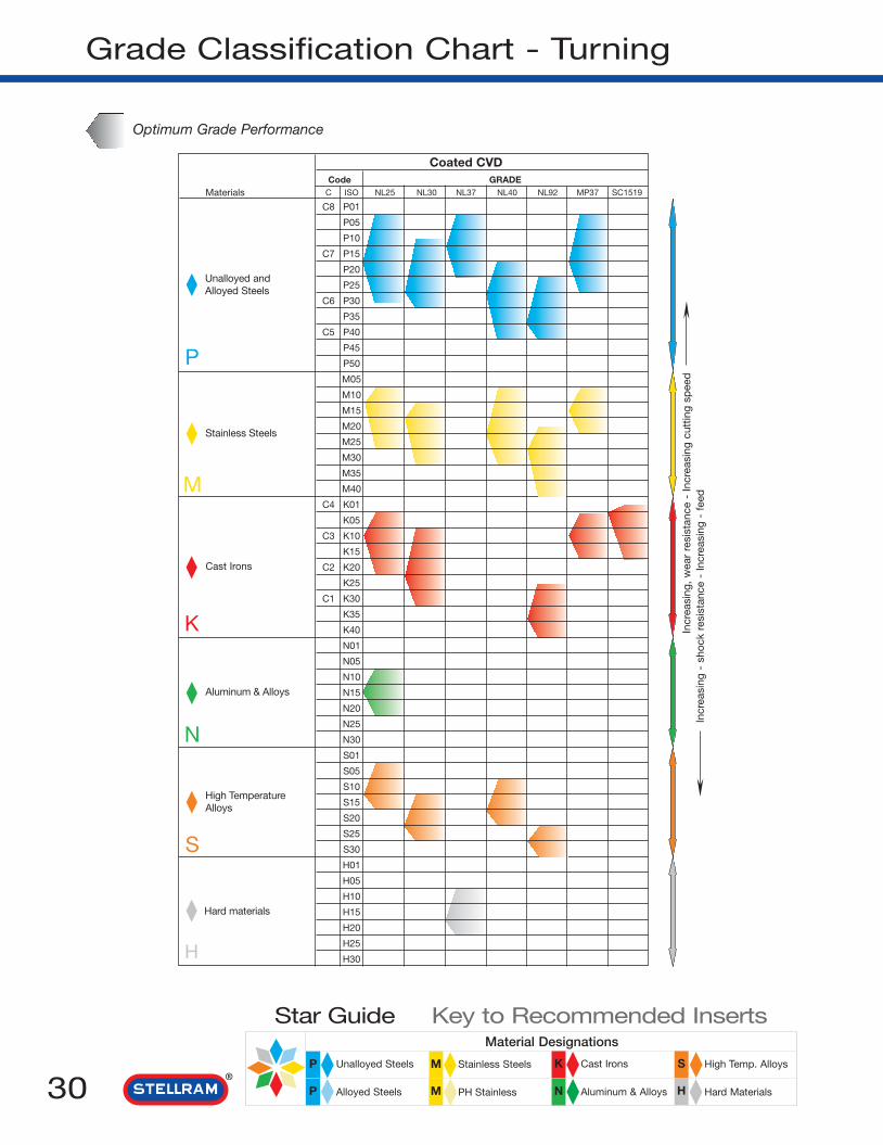
Grade Classification Chart - Turning
Optimum Grade Performance
Stainless Steels
Aluminum & Alloys
High TemperatureAlloys
Hard materials
Cast Irons
S
N
K
M
P
Incr
easi
ng -
sho
ck r
esis
tanc
e -
Incr
easi
ng -
fee
dIn
crea
sing
, w
ear
resi
stan
ce -
Incr
easi
ng c
uttin
g sp
eed
Coated CVDCode GRADE
Materials C ISO NL25 NL30 NL37 NL40 NL92 MP37 SC1519
C8 P01
P05
P10
C7 P15
P20
P25
C6 P30
P35
C5 P40
P45
P50
M05
M10
M15
M20
M25
M30
M35
M40
C4 K01
K05
C3 K10
K15
C2 K20
K25
C1 K30
K35
K40
N01
N05
N10
N15
N20
N25
N30
S01
S05
S10
S15
S20
S25
S30
H01
H05
H10
H15
H20
H25
H30
Unalloyed andAlloyed Steels
N
Material Designations
High Temp. Alloys
Hard Materials
Cast Irons
Aluminum & Alloys
Stainless Steels
PH Stainless
Unalloyed Steels
Alloyed Steels
Star Guide Key to Recommended Inserts
P M K S
HMP
H

31
Grade Classification Chart - Turning
N
Material Designations
High Temp. Alloys
Hard Materials
Cast Irons
Aluminum & Alloys
Stainless Steels
PH Stainless
Unalloyed Steels
Alloyed Steels
Star Guide Key to Recommended Inserts
P M K S
HMP
Incr
easi
ng -
sho
ck r
esis
tanc
e -
Incr
easi
ng -
fee
dIn
crea
sing
, w
ear
resi
stan
ce -
Incr
easi
ng c
uttin
g sp
eed
Optimum Grade Performance
Unalloyed andAlloyed Steels
Stainless Steels
Aluminum & Alloys
High TemperatureAlloys
Hard materials
Cast Irons
S
H
N
K
M
P
Coated PVD UncoatedCode GRADE GRADE
SFZ SP0864SP3036 SP4036
H21 GH1 GH2Materials C ISOSP3064 SP4064
C8 P01
P05
P10
C7 P15
P20
P25
C6 P30
P35
C5 P40
P45
P50
M05
M10
M15
M20
M25
M30
M35
M40
C4 K01
K05
C3 K10
K15
C2 K20
K25
C1 K30
K35
K40
N01
N05
N10
N15
N20
N25
N30
S01
S05
S10
S15
S20
S25
S30
H01
H05
H10
H15
H20
H25
H30

32 N
Material Designations
High Temp. Alloys
Hard Materials
Cast Irons
Aluminum & Alloys
Stainless Steels
PH Stainless
Unalloyed Steels
Alloyed Steels
Star Guide Key to Recommended Inserts
P M K S
HMP
Ceramic Grade Information
Recommended Cutting Conditions
Speed SFMISO Materials Rm SA7402 SA8204 SA8405
to be machined and Ceramic Ceramic CeramicMax - min Max - min Max - min
700-950 N/mm2
- - - - - -200-280 HBN
950-1200 N/mm2
280-355 HBN1310 330 - - - -
1200-1400 N/mm2
355-415 HBN890 165 - - - -
Grey
GG-Ft2300 490 2625 490 2950 490
Spheroidal-Ductile
GGG-FGS1980 490 2265 490 2560 490
Malleable
GTS - MN/MP1340 490 1540 490 1740 490
Iron Based - - - - 750 375
Cobalt Based - - - - 610 300
Nickel Based - - - - 655 330
Titanium Based - - - - - -
Hard steels> 1400 N/mm2
> 415 HBN280 65 - - - -
Chilled cast irons 1400 N/mm2
400 HBN260 65 280 65 - -
Alloyed
Steels
High
Temperature
Alloys
Cast Irons
P
K
S
H
Please refer to the Stellram Ceramic Catalog.

33
Ceramic Grade Information
N
Material Designations
High Temp. Alloys
Hard Materials
Cast Irons
Aluminum & Alloys
Stainless Steels
PH Stainless
Unalloyed Steels
Alloyed Steels
Star Guide Key to Recommended Inserts
P M K S
HMP
Grade Composition Colour Density Hardness (Hv) Fracture Toughness Thermal(g/cm3) (N/mm3/2) Conductivity
(cal/cm.secºC)
SA7402 Al2O3+TiCN Black 4.3 2200 4.5 0.08
SA8204 Si3N4 Grey 3.7 1680 6.0 0.05
SA8405 Si3N4 + TiN Brown 3.5 1750 6.5 0.05
HighTemperatureAlloys
Hard materials
H
Unalloyed andAlloyed Steels
Cast Irons
K
P
Physical Properties
ISO Grade Chart
MATERIALSTO BE MACHINED
S
CODE CERAMIC
C ISO SA7402 SA8204 SA8405
C8 P01
P05
P10
C7 P15
P20
P25
C6 P30
P35
C5 P40
P50
C4 K01
K05
C3 K10
K15
C2 K20
K25
C1 K30
K35
K40
S01
S05
S10
S15
S20
S25
S30
H01
H05
H10
H15
H20
H25
H30
Please refer to the Stellram Ceramic Catalog.

34
ANSI Insert Designation
S N M 4G1 2 3 4 5
1 Shape 2 Clearance
A C D A B
E F
C DE
Other normal clearancesrequiring SPECIALspecification Symbol O.
85° 82° 80° 55° 75°
H K L M O
120° 55° 90° 86° 135°
P R S T V
108° 360° 90° 60° 35°
W
80°
G N
P
3° 5° 7° 15°
20° 25° 30° 0°
11°
d m d
m
d md
m
s
B
* See tables below.
Valid for shapes:C, E, H, M, O, P, S, T, R, W
4 Type
70° - 90° 70° - 90°
70° - 90° 70° - 90° 40° - 60°
40° - 60° 40° - 60° 40° - 60°
Specialfeaturerequiringadditionalspecification
A C F GB
H J M N Q
R T U W X
Class d m sA inch ±0.0002 ±0.0010 ±0.001B inch ±0.0002 ±0.0010 ±0.005C inch ±0.0005 ±0.0010 ±0.001D inch ±0.0005 ±0.0010 ±0.005E inch ±0.0010 ±0.0010 ±0.001F inch ±0.0002 ±0.0005 ±0.001G inch ±0.0010 ±0.0010 ±0.005H inch ±0.0005 ±0.0005 ±0.001J inch ±0.0002 * ±0.001K inch ±0.0005 * ±0.001L inch ±0.0010 * ±0.001M inch * * ±0.005U inch * * ±0.005N inch * * ±0.001
7/32
1/4
5/16
3/8
1/2
5/8
3/4
IC d m
Valid for shape D only
±0.002±0.002±0.002±0.002±0.003±0.004±0.004
±0.004±0.004±0.004±0.004±0.006±0.007±0.007
IC d mM, N, UJ, K, L, M, N, U
3/16
7/32
1/4
5/16
3/8
1/2
5/8
3/4
1
11/4
±0.002
±0.002
±0.002
±0.002
±0.002
±0.003
±0.004
±0.004
±0.005
±0.006
±0.003
±0.003
±0.003
±0.003
±0.003
±0.005
±0.007
±0.007
±0.010
±0.010
±0.003
±0.003
±0.003
±0.003
±0.003
±0.005
±0.006
±0.006
±0.007
±0.008
±0.005
±0.005
±0.005
±0.005
±0.005
±0.008
±0.011
±0.011
±0.015
±0.015
3 Tolerance

35
ANSI Insert Designation
8 Edge Condition
3 2 A6 7 8 9 10
5 SizeFor equal sided inserts, thisindicates the inscribed circle(IC) in 1/8".
For rectangles andparallelograms,2 digits are necessary.
1stNumber
digitof 1/8"in width.
2ndNumber
digitof 1/4"in length.
=
=
Examples:
1 = 1/8
1-2 = 5/32
1-5 = 3/16
1-8 = 7/32
2 = 1/4
2-5 = 5/16
3 = 3/8
4 = 1/2
5 = 5/8
6 = 3/4
7 = 7/8
8 = 1
10 = 1 1/4
6 Thickness 7 Corner
A, B,
C, N,
O, W.
H, M,
R, T.
F, G,
J, U.
s
s
s
s
This indicates the insert thickness in 1/16" increments.
Examples:
1 = 1/16
1-5 = 3/32
2 = 1/8
2-5 = 5/32
3 = 3/16
3-5 = 7/32
4 = 1/4
5 = 5/16
6 = 3/8
7 = 7/16
8 = 1/2
9 = 9/16
10 = 5/8
IC
r
This indicates the form on the corner in 1/64" incrementsfor those with a cornerradius.
0 = 0.002
0-2 = 0.004
0-5 = 0.008
1 = 1/64
2 = 1/32
3 = 3/64
4 = 1/16
5 = 5/64
Examples:
6 = 3/32
7 = 7/64
8 = 1/8
10 = 5/32
12 = 3/16
14 = 7/32
16 = 1/4
X = ANYOTHER
Faceted Inserts (A Style only)
Chamferedcorner
Wiper edge
Minor cutting edge
Major cutting edge
k˚
A = 45°
D = 60°
E = 75°
F = 85°
G = 87°
P = 90°
Z = ANYOTHER
Facet Angle (K)
1st letter:
Facet Clearance(Primary Facet)
2nd letter:
A = 3°
B = 5°
C = 7°
D = 15°
E = 20°
F = 25°
G = 30°
N = 0°
P = 11°
Z = ANYOTHER
Hone
Hone
Honed Edge(Rounded Corner):
A0·0005
<0·003
B0·003
<0·005
C0·005
<0·007
E F J K
Rounded edge.
Sharp edge.
Polished to 4Microinch AA.rake face only.
Doublechamfered
cutting edge.
Double chamfered and rounded cutting edge.
S
Chamfered and rounded cutting edge.
Chamfered cutting edge.
P T
9 Hand 10 Facet Size
RRight Hand
Insert
LLeft Hand
Insert
NNeutral
Examples:1 = 1/64
2 = 1/32
3 = 3/64
4 = 1/16
5 = 5/64
6 = 3/32
7 = 7/64
8 = 1/8
9 = 9/64
10 = 5/32
Secondary FacetPrimary
Facet Primary Facets
NeutralR/L
ll
This indicates thelength of the primaryfacet in increments of approximately 1/64
".
Used only following a double letter in the7th position.
OPTIONAL:This is not an ISOstandard.

36
S N M 12G1 2 3 4 5
1 Shape 2 Clearance
A C D A B
E F
C DE
Other normal clearancesrequiring SPECIALspecification Symbol O.
85° 82° 80° 55° 75°
H K L M O
120° 55° 90° 86° 135°
P R S T V
108° 360° 90° 60° 35°
W
80°
G N
P
3° 5° 7° 15°
20° 25° 30° 0°
11°
d m d
m
d md
m
s
B
3 Tolerance
* See tables below.
Class d m sA mm ±0,025 ±0,005 ±0,025C mm ±0,025 ±0,013 ±0,025E mm ±0,025 ±0,025 ±0,025F mm ±0,013 ±0,005 ±0,025G mm ±0,025 ±0,025 ±0,13H mm ±0,013 ±0,013 ±0,025J mm * ±0,005 ±0,025K mm * ±0,013 ±0,025L mm * ±0,025 ±0,025M mm * * ±0,127U mm * * ±0,127N mm * * ±0,025
Valid for shape D only (M & N Tolerance)
IC d m
5,566,357,949,52512,715,87519,05
±0,11±0,11±0,11±0,11±0,15±0,18±0,18
±0,05±0,05±0,05±0,05±0,08±0,10±0,10
Valid for shapes:C, E, H, M, O, P, S, T, R, W
IC d mJ, K, L, M, N U M, N U
±0,08±0,08±0,08±0,08±0,08±0,08±0,08±0,08±0,13±0,13±0,18±0,18±0,18±0,18±0,25±0,25±0,25±0,25
±0,05±0,05±0,05±0,05±0,05±0,05±0,05±0,05±0,08±0,08±0,1±0,1±0,1±0,1±0,13±0,13±0,15±0,15
4,765,5666,357,9489,525101212,715,8751619,05202525,431,7532
±0,08±0,08±0,08±0,08±0,08±0,08±0,08±0,08±0,13±0,13±0,15±0,15±0,15±0,15±0,18±0,18±0,2±0,2
±0,13±0,13±0,13±0,13±0,13±0,13±0,13±0,13±0,2±0,2±0,27±0,27±0,27±0,27±0,38±0,38±0,38±0,38
4 Type
70° - 90° 70° - 90°
70° - 90° 70° - 90° 40° - 60°
40° - 60° 40° - 60° 40° - 60°
Specialfeaturerequiringadditionalspecification
A C F GB
H J M N Q
R T U W X
ISO Insert Designation

37
ISO Insert Designation
04 086 7
5 Size
6 Thickness
Integers to be preceded by a 0 (zero).Disregard any decimals. e.g. 9,525 = 09
L
I
O
I
P
I
C, D,E, M,V
I
H
I
A, B,K
I
R
I
S
I
T
I
W
I
s Examples:
01 = 1,588
T1 = 1,984
02 = 2,381
03 = 3,175
T3 = 3,969
04 = 4,763
05 = 5,556
06 = 6,350
07 = 7,938
09 = 9,525
11 = 11,113
12 = 12,700
14 = 14,288
15 = 15,875
E8
4T9
7 Corner
A = 45°
D = 60°
E = 75°
F = 85°
G = 87°
P = 90°
Z = ANY OTHER
A = 3°
B = 5°
C = 7°
D = 15°
E = 20°
F = 25°
G = 30°
N = 0°
P = 11°
Z = ANY OTHER
Inserts with wiper edgesCutting edge Angle (κr) Wiper edge normal
1st letter: Clearance 2nd letter: (�n)
A, B,
C, N,
O, W.
H, M,
R, T.
F, G,
J, U.
s
ss
Integers to be preceded by a 0 (zero) or the letter T.Disregard any decimals.
7 Corner continuedInserts with rounded corners. The corner radiusis indicated in 0,1mm. Integers to be preceded bya 0 (zero). If the corner is not rounded, use thesymbol of designation 00 (zero zero).
Examples:
00 = SHARP CORNER
01 = 0,1
02 = 0,2
04 = 0,4
08 = 0,8
12 = 1,2
16 = 1,6
20 = 2,0
24 = 2,4
28 = 2,8
32 = 3,2
40 = 4,0
48 = 4,8
56 = 5,6
64 = 6,4
X = ANY OTHER
8 Edge Condition
Symbol
Sharp F
Honed E(Rounded)
Chamfered T(Negative Land)
Chamfered + SHoned
9 Geometry Designation1A, 2B, 2N, 3F, 3G, 3J, 3M, 4M, 4T,
4U, 5V, 91, 15, 61, 62, 64, 66, 73,
3G, M
-
Chamferedcorner
Wiper edge
Minor cutting edge
Major cutting edge
κr
rε

C Style Turning Inserts
CCGT
N
Material Designations
High Temp. Alloys
Hard Materials
Cast Irons
Aluminum & Alloys
Stainless Steels
PH Stainless
Unalloyed Steels
Alloyed Steels
Star Guide Key to Recommended Inserts
P M K S
HMP
Dimensions for CCGT and CCMT
Size d l s r m m1 hin in in in in in in
21.50.2 0.250 0.254 0.094 0.003 0.067 0.008 0.11021.50.5 0.250 0.254 0.094 0.008 0.065 0.036 0.11021.51 0.250 0.254 0.094 0.016 0.061 0.033 0.11021.52 0.250 0.254 0.094 0.031 0.052 0.028 0.11032.50 0.375 0.377 0.156 0.000 0.104 0.057 0.17332.50.2 0.375 0.377 0.156 0.003 0.102 0.056 0.17332.50.5 0.375 0.377 0.156 0.008 0.100 0.055 0.17332.51 0.375 0.377 0.156 0.016 0.096 0.053 0.17332.52 0.375 0.377 0.156 0.031 0.087 0.048 0.173431 0.500 0.508 0.188 0.016 0.130 0.072 0.217432 0.500 0.508 0.188 0.031 0.122 0.067 0.217433 0.500 0.508 0.188 0.047 0.113 0.062 0.217
62 GeometryGrades CVD COATED PVD COATED UNCOATED
38
Grades CVD COATED PVD COATED UNCOATED
NL2
5
NL3
0
NL3
7
NL4
0
NL9
2
SC
1519
MP
37
SP
0864
SP
3036
SP
3064
SP
4036
SP
4064
SFZ
H21
GH
1
GH
2
NL2
5
NL3
0
NL3
7
NL4
0
NL9
2
SC
1519
MP
37
SP
0864
SP
3036
SP
3064
SP
4036
SP
4064
SFZ
H21
GH
1
GH
2
Indicates stocked item and material application range.
For Toolholders External: SCAC, SCLC see pages 118 - 119
Internal: SCLC see page 146
Part Number
ANSIISO
CCGT21.50.2A-62 ◆◆CCGT060201E-62 ◆◆CCGT21.50.5A-62 ◆◆CCGT060202E-62 ◆◆
CCGT21.51A-62 ◆◆CCGT060204E-62 ◆◆
CCGT32.50A-62 ◆◆ ◆◆CCGT09T300E-62 ◆◆ ◆◆CCGT32.50.2A-62 ◆◆ ◆◆CCGT09T301E-62 ◆◆ ◆◆CCGT32.50.5A-62 ◆◆CCGT09T302E-62 ◆◆
CCGT32.51A-62 ◆◆CCGT09T304E-62 ◆◆
CCGT32.52A-62 ◆◆CCGT09T308E-62 ◆◆

N
Material Designations
High Temp. Alloys
Hard Materials
Cast Irons
Aluminum & Alloys
Stainless Steels
PH Stainless
Unalloyed Steels
Alloyed Steels
Star Guide Key to Recommended Inserts
P M K S
HMP
C Style Turning Inserts
CCMT
CCMT21.50.5A-3G ◆◆ ◆◆CCMT060202E-3G ◆
CCMT21.51A-3G ◆◆ ◆◆CCMT060204E-3G ◆ ◆
CCMT21.52A-3G ◆◆CCMT060208E-3G ◆ ◆CCMT32.50.5A-3G ◆◆CCMT09T302E-3G ◆
CCMT32.51A-3G ◆◆ ◆◆ ◆◆CCMT09T304E-3G ◆ ◆
CCMT32.52A-3G ◆◆ ◆◆ ◆◆ ◆◆CCMT09T308E-3G ◆ ◆
CCMT431A-3G ◆◆CCMT120404E-3G ◆
CCMT432A-3G ◆◆ ◆◆CCMT120408E-3G ◆
CCMT433A-3GCCMT120412E-3G
Grades CVD COATED PVD COATED UNCOATED
3G Geometry
39
NL2
5
NL3
0
NL3
7
NL4
0
NL9
2
SC
1519
MP
37
SP
0864
SP
3036
SP
3064
SP
4036
SP
4064
SFZ
H21
GH
1
GH
2
73 GeometryGrades CVD COATED PVD COATED UNCOATED
Part Number
ANSIISO
CCMT21.50.5A-73 ◆◆CCMT060202E-73 ◆◆
CCMT21.51A-73 ◆◆ ◆◆ ◆◆CCMT060204E-73 ◆◆ ◆◆ ◆◆
CCMT21.52A-73 ◆◆ ◆◆CCMT060208E-73 ◆◆ ◆◆
CCMT32.51A-73 ◆◆ ◆◆ ◆◆CCMT09T304E-73 ◆◆ ◆◆ ◆◆
CCMT32.52A-73 ◆◆ ◆◆ ◆◆CCMT09T308E-73 ◆◆ ◆◆ ◆◆
CCMT431A-73 ◆◆ ◆◆CCMT120404E-73 ◆◆ ◆◆
CCMT432A-73 ◆◆ ◆◆ ◆◆CCMT120408E-73 ◆◆ ◆◆ ◆◆
CCMT433A-73 ◆◆CCMT120412E-73 ◆◆
NL2
5
NL3
0
NL3
7
NL4
0
NL9
2
SC
1519
MP
37
SP
0864
SP
3036
SP
3064
SP
4036
SP
4064
SFZ
H21
GH
1
GH
2
Indicates stocked item and material application range.
For Toolholders External: SCAC, SCLC see pages 118 - 119 Internal: SCLC see page 146

40 N
Material Designations
High Temp. Alloys
Hard Materials
Cast Irons
Aluminum & Alloys
Stainless Steels
PH Stainless
Unalloyed Steels
Alloyed Steels
Star Guide Key to Recommended Inserts
P M K S
HMP
NL2
5
NL3
0
NL3
7
NL4
0
NL9
2
SC
1519
MP
37
SP
0864
SP
3036
SP
3064
SP
4036
SP
4064
SFZ
H21
GH
1
GH
2
Dimensions for CNGP, CNMA, CNMG and CNMMSize d l s r m m1 h
in in in in in in in322 0.375 0.377 0.125 0.031 0.095 0.048 0.150430.2 0.500 0.508 0.188 0.003 0.136 0.075 0.203430.5 0.500 0.508 0.188 0.008 0.135 0.074 0.203431 0.500 0.508 0.188 0.016 0.130 0.072 0.203432 0.500 0.508 0.188 0.031 0.122 0.067 0.203433 0.500 0.508 0.188 0.047 0.113 0.062 0.203434 0.500 0.508 0.188 0.063 0.104 0.057 0.203542 0.625 0.634 0.250 0.031 0.156 0.086 0.250543 0.625 0.634 0.250 0.047 0.148 0.081 0.250544 0.625 0.634 0.250 0.063 0.139 0.076 0.250548 0.625 0.634 0.250 0.125 0.147 0.057 0.250642 0.750 0.764 0.250 0.031 0.191 0.105 0.312643 0.750 0.764 0.250 0.047 0.182 0.100 0.312644 0.750 0.764 0.250 0.063 0.174 0.095 0.312648 0.750 0.764 0.250 0.125 0.139 0.076 0.312
C Style Turning Inserts
CNGP
3F GeometryGrades CVD COATED PVD COATED UNCOATED
Indicates stocked item and material application range.
NL2
5
NL3
0
NL3
7
NL4
0
NL9
2
SC
1519
MP
37
SP
0864
SP
3036
SP
3064
SP
4036
SP
4064
SFZ
H21
GH
1
GH
2
Grades CVD COATED PVD COATED UNCOATED
For Toolholders External: MCGN, MCKN, MCLN, MCRN see pages 100 - 103Internal: MCKN, MCLN see pages 139 - 140
Part Number
ANSIISO
CNGP430.2-3F ◆◆ ◆◆CNGG120401F-3F ◆◆ ◆
CNGP430.5-3F ◆◆ ◆◆CNGG120402F-3F ◆◆ ◆
CNGP431-3F ◆◆ ◆◆ ◆◆CNGG120404F-3F ◆◆ ◆ ◆
CNGP432-3F ◆◆ ◆◆ ◆◆CNGG120408F-3F ◆◆ ◆ ◆
CNGP433-3F ◆◆CNGG120412F-3F ◆◆

41N
Material Designations
High Temp. Alloys
Hard Materials
Cast Irons
Aluminum & Alloys
Stainless Steels
PH Stainless
Unalloyed Steels
Alloyed Steels
Star Guide Key to Recommended Inserts
P M K S
HMP
C Style Turning Inserts
CNMA, CNMG
NL2
5
NL3
0
NL3
7
NL4
0
NL9
2
SC
1519
MP
37
SP
0864
SP
3036
SP
3064
SP
4036
SP
4064
SFZ
H21
GH
1
GH
2
Grades CVD COATED PVD COATED UNCOATED
Part Number
ANSIISO
CNMA431A ◆CNMA120404E ◆
CNMA432A ◆ ◆ ◆CNMA120408E ◆
CNMA433A ◆ ◆CNMA120412E ◆
CNMA434A ◆CNMA120416E ◆
CNMA543A ◆ ◆ ◆CNMA160612E ◆ ◆
CNMA548A ◆CNMA160632E ◆
CNMA643A ◆ ◆CNMA190612E ◆
CNMA644A ◆ ◆CNMA190616E ◆
CNMA648A ◆ ◆
Flat TopGrades CVD COATED PVD COATED UNCOATED
NL2
5
NL3
0
NL3
7
NL4
0
NL9
2
SC
1519
MP
37
SP
0864
SP
3036
SP
3064
SP
4036
SP
4064
SFZ
H21
GH
1
GH
2CNMG430.5A-1A ◆◆
CNMG120402E-1A ◆CNMG431A-1A ◆◆ ◆◆ ◆◆ ◆◆
CNMG120404E-1A ◆ ◆CNMG432A-1A ◆◆ ◆◆
CNMG120408E-1A ◆
1A Geometry
Indicates stocked item and material application range.
For Toolholders External: MCGN, MCKN, MCLN, MCRN see pages 100 - 103Internal: MCKN, MCLN see pages 139 - 140
91 GeometryCNMG431A-91 ◆◆ ◆◆
CNMG120404E-91 ◆CNMG432A-91 ◆◆ ◆◆
CNMG120408E-91 ◆CNMG433A-91 ◆◆ ◆◆
CNMG120412E-91

C Style Turning Inserts
CNMG
NL2
5
NL3
0
NL3
7
NL4
0
NL9
2
SC
1519
MP
37
SP
0864
SP
3036
SP
3064
SP
4036
SP
4064
SFZ
H21
GH
1
GH
2
N
Material Designations
High Temp. Alloys
Hard Materials
Cast Irons
Aluminum & Alloys
Stainless Steels
PH Stainless
Unalloyed Steels
Alloyed Steels
Star Guide Key to Recommended Inserts
P M K S
HMP
2B GeometryGrades CVD COATED PVD COATED UNCOATED
42
Part Number
ANSIISO
CNMG431A-2B ◆CNMG120404E-2B ◆
CNMG432A-2B ◆◆ ◆◆ CNMG120408E-2B ◆
CNMG643A-2B ◆◆CNMG190612E-2B
2N Geometry
NL2
5
NL3
0
NL3
7
NL4
0
NL9
2
SC
1519
MP
37
SP
0864
SP
3036
SP
3064
SP
4036
SP
4064
SFZ
H21
GH
1
GH
2
Grades CVD COATED PVD COATED UNCOATED
CNMG322A-2N ◆◆CNMG090308E-2N ◆◆
CNMG431A-2N ◆◆ ◆◆ ◆◆ ◆◆ ◆◆CNMG120404E-2N ◆◆ ◆◆ ◆ ◆◆ ◆
CNMG432A-2N ◆◆ ◆◆ ◆◆ ◆◆ ◆◆ ◆◆ ◆◆CNMG120408E-2N ◆◆ ◆◆ ◆ ◆◆ ◆◆ ◆ ◆
CNMG433A-2N ◆◆ ◆◆ ◆◆ ◆◆ ◆◆CNMG120412E-2N ◆◆ ◆◆ ◆ ◆◆ ◆
CNMG542A-2N ◆◆CNMG160608E-2N ◆ ◆◆
CNMG543A-2N ◆◆ ◆◆ ◆◆CNMG160612E-2N ◆◆ ◆ ◆◆
CNMG544A-2N ◆CNMG160616E-2N ◆
CNMG643A-2N ◆◆ ◆◆CNMG190612E-2N ◆◆ ◆◆
CNMG644A-2N ◆◆CNMG190616E-2N ◆◆
3G GeometryCNMG431A-3G ◆◆ ◆◆ ◆◆ ◆◆ ◆◆
CNMG120404E-3G ◆ ◆CNMG432A-3G ◆◆ ◆◆ ◆◆ ◆◆ ◆◆ ◆◆
CNMG120408E-3G ◆ ◆CNMG433A-3G ◆◆ ◆◆ ◆◆ ◆◆
CNMG120412E-3G ◆ ◆
For Toolholders External: MCGN, MCKN, MCLN, MCRN see pages 100 - 103Internal: MCKN, MCLN see pages 139 - 140

N
Material Designations
High Temp. Alloys
Hard Materials
Cast Irons
Aluminum & Alloys
Stainless Steels
PH Stainless
Unalloyed Steels
Alloyed Steels
Star Guide Key to Recommended Inserts
P M K S
HMP
C Style Turning Inserts
CNMG
43
NL2
5
NL3
0
NL3
7
NL4
0
NL9
2
SC
1519
MP
37
SP
0864
SP
3036
SP
3064
SP
4036
SP
4064
SFZ
H21
GH
1
GH
2
3G Geometry continued
Grades CVD COATED PVD COATED UNCOATED
Part Number
ANSIISO
CNMG542A-3G ◆◆ ◆◆CNMG160608E-3G ◆
CNMG543A-3G ◆◆ ◆◆CNMG160612E-3G ◆
CNMG643A-3G ◆◆ ◆◆CNMG190612E-3G ◆ ◆
Indicates stocked item and material application range.
For Toolholders External: MCGN, MCKN, MCLN, MCRN see pages 100 - 103Internal: MCKN, MCLN see pages 139 - 140
3M Geometry
NL2
5
NL3
0
NL3
7
NL4
0
NL9
2
SC
1519
MP
37
SP
0864
SP
3036
SP
3064
SP
4036
SP
4064
SFZ
H21
GH
1
GH
2
Grades CVD COATED PVD COATED UNCOATED
CNMG432A-3M ◆◆ ◆◆CNMG120408E-3M ◆◆ ◆
CNMG433A-3M ◆◆ ◆◆CNMG120412E-3M ◆◆ ◆
3J GeometryCNMG431A-3J ◆◆ ◆◆ ◆◆ ◆◆
CNMG120404E-3J ◆ ◆ ◆ ◆CNMG432A-3J ◆◆ ◆◆ ◆◆ ◆◆
CNMG120408E-3J ◆ ◆ ◆ ◆CNMG433A-3J ◆◆ ◆◆ ◆◆
CNMG120412E-3J ◆ ◆ ◆CNMG434A-3J ◆◆ ◆◆
CNMG120416E-3J ◆ ◆CNMG542A-3J ◆◆
CNMG160608E-3J ◆CNMG543A-3J ◆◆ ◆◆ ◆◆
CNMG160612E-3J ◆ ◆ ◆CNMG643A-3J ◆◆
CNMG190612E-3J ◆CNMG644A-3J ◆◆
CNMG190616E-3J ◆
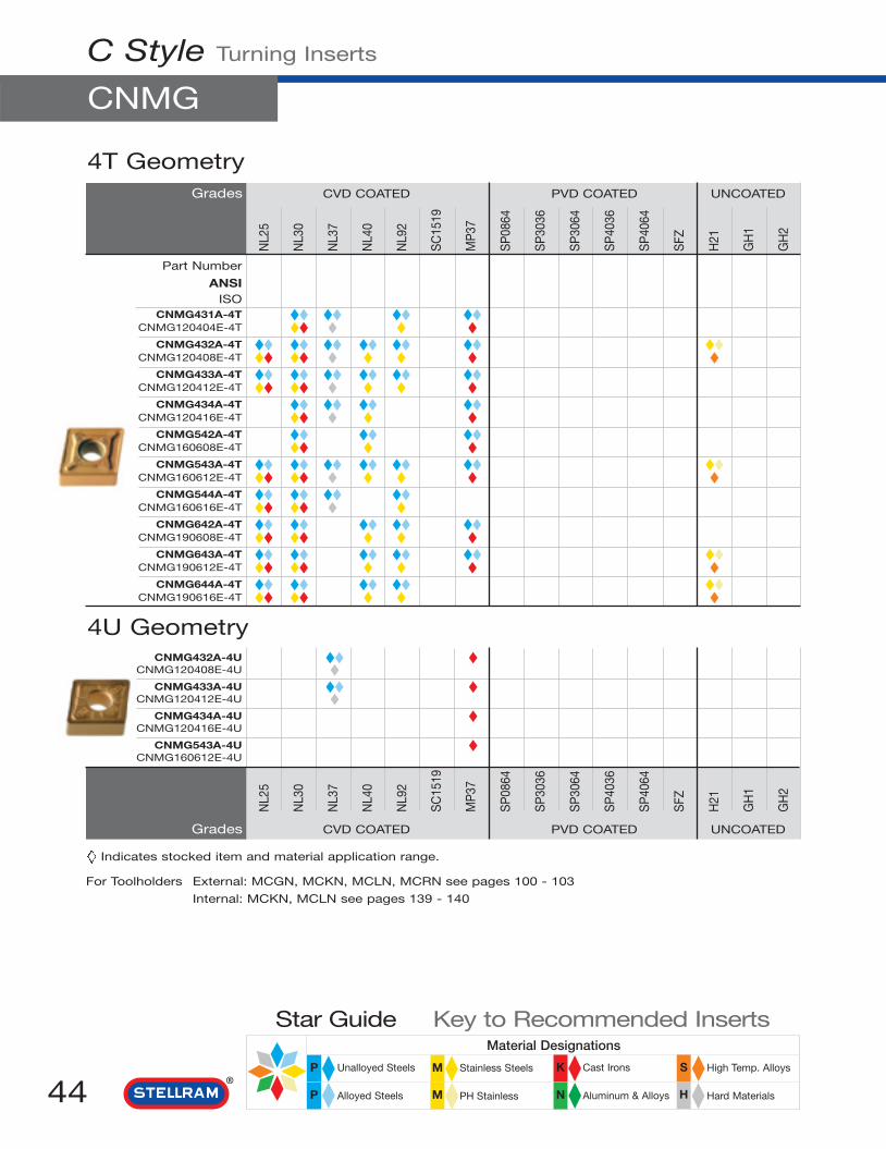
N
Material Designations
High Temp. Alloys
Hard Materials
Cast Irons
Aluminum & Alloys
Stainless Steels
PH Stainless
Unalloyed Steels
Alloyed Steels
Star Guide Key to Recommended Inserts
P M K S
HMP44
C Style Turning Inserts
CNMG
NL2
5
NL3
0
NL3
7
NL4
0
NL9
2
SC
1519
MP
37
SP
0864
SP
3036
SP
3064
SP
4036
SP
4064
SFZ
H21
GH
1
GH
2
4T GeometryGrades CVD COATED PVD COATED UNCOATED
Part Number
ANSIISO
CNMG431A-4T ◆◆ ◆◆ ◆◆ ◆◆CNMG120404E-4T ◆◆ ◆ ◆ ◆
CNMG432A-4T ◆◆ ◆◆ ◆◆ ◆◆ ◆◆ ◆◆ ◆◆CNMG120408E-4T ◆◆ ◆◆ ◆ ◆ ◆ ◆ ◆
CNMG433A-4T ◆◆ ◆◆ ◆◆ ◆◆ ◆◆ ◆◆CNMG120412E-4T ◆◆ ◆◆ ◆ ◆ ◆ ◆
CNMG434A-4T ◆◆ ◆◆ ◆◆ ◆◆CNMG120416E-4T ◆◆ ◆ ◆ ◆
CNMG542A-4T ◆◆ ◆◆ ◆◆CNMG160608E-4T ◆◆ ◆ ◆
CNMG543A-4T ◆◆ ◆◆ ◆◆ ◆◆ ◆◆ ◆◆ ◆◆CNMG160612E-4T ◆◆ ◆◆ ◆ ◆ ◆ ◆ ◆
CNMG544A-4T ◆◆ ◆◆ ◆◆ ◆◆CNMG160616E-4T ◆◆ ◆◆ ◆ ◆
CNMG642A-4T ◆◆ ◆◆ ◆◆ ◆◆ ◆◆CNMG190608E-4T ◆◆ ◆◆ ◆ ◆ ◆
CNMG643A-4T ◆◆ ◆◆ ◆◆ ◆◆ ◆◆ ◆◆CNMG190612E-4T ◆◆ ◆◆ ◆ ◆ ◆ ◆
CNMG644A-4T ◆◆ ◆◆ ◆◆ ◆◆ ◆◆CNMG190616E-4T ◆◆ ◆◆ ◆ ◆ ◆
4U GeometryCNMG432A-4U ◆◆ ◆
CNMG120408E-4U ◆ ◆CNMG433A-4U ◆◆ ◆
CNMG120412E-4U ◆ ◆CNMG434A-4U ◆
CNMG120416E-4U ◆CNMG543A-4U ◆
CNMG160612E-4U ◆
NL2
5
NL3
0
NL3
7
NL4
0
NL9
2
SC
1519
MP
37
SP
0864
SP
3036
SP
3064
SP
4036
SP
4064
SFZ
H21
GH
1
GH
2
Grades CVD COATED PVD COATED UNCOATED
Indicates stocked item and material application range.
For Toolholders External: MCGN, MCKN, MCLN, MCRN see pages 100 - 103
Internal: MCKN, MCLN see pages 139 - 140

N
Material Designations
High Temp. Alloys
Hard Materials
Cast Irons
Aluminum & Alloys
Stainless Steels
PH Stainless
Unalloyed Steels
Alloyed Steels
Star Guide Key to Recommended Inserts
P M K S
HMP 45
C Style Turning Inserts
CNMG, CNMM
NL2
5
NL3
0
NL3
7
NL4
0
NL9
2
SC
1519
MP
37
SP
0864
SP
3036
SP
3064
SP
4036
SP
4064
SFZ
H21
GH
1
GH
2
5V GeometryGrades CVD COATED PVD COATED UNCOATED
Part Number
ANSIISO
CNMG432A-5V ◆CNMG120408E-5V ◆
CNMG433A-5V ◆◆ ◆◆ ◆CNMG120412E-5V ◆ ◆
CNMG543A-5V ◆◆ ◆CNMG160612E-5V ◆ ◆
CNMG643A-5V ◆◆ ◆CNMG190612E-5V ◆
CNMG644A-5V ◆◆CNMG190616E-5V ◆
4M Geometry
NL2
5
NL3
0
NL3
7
NL4
0
NL9
2
SC
1519
MP
37
SP
0864
SP
3036
SP
3064
SP
4036
SP
4064
SFZ
H21
GH
1
GH
2
Grades CVD COATED PVD COATED UNCOATED
CNMM432A-4M ◆◆CNMM120408E-4M ◆◆
CNMM643A-4M ◆◆CNMM190612E-4M ◆◆
CNMM644A-4M ◆◆CNMM190616E-4M ◆◆
Indicates stocked item and material application range.
For Toolholders External: MCGN, MCKN, MCLN, MCRN see pages 100 - 103
Internal: MCKN, MCLN see pages 139 - 140

C Style Turning Inserts
CPGH
NL2
5
NL3
0
NL3
7
NL4
0
NL9
2
SC
1519
MP
37
SP
0864
SP
3036
SP
3064
SP
4036
SP
4064
SFZ
H21
GH
1
GH
2
N
Material Designations
High Temp. Alloys
Hard Materials
Cast Irons
Aluminum & Alloys
Stainless Steels
PH Stainless
Unalloyed Steels
Alloyed Steels
Star Guide Key to Recommended Inserts
P M K S
HMP
Dimensions for CPGH
Size d l s r m m1 hin in in in in in in
2.521 0.312 0.374 0.125 0.016 0.078 - 0.120
2C GeometryGrades CVD COATED PVD COATED UNCOATED
46
Part Number
ANSIISO
CPGH2.521A-2C ◆◆CPGH080304E-2C ◆
Indicates stocked item and material application range.
For Toolholders External: SCLP see page 120
Internal: SCLP see page 147

N
Material Designations
High Temp. Alloys
Hard Materials
Cast Irons
Aluminum & Alloys
Stainless Steels
PH Stainless
Unalloyed Steels
Alloyed Steels
Star Guide Key to Recommended Inserts
P M K S
HMP
C Style Turning Inserts
CPMT
47
NL2
5
NL3
0
NL3
7
NL4
0
NL9
2
SC
1519
MP
37
SP
0864
SP
3036
SP
3064
SP
4036
SP
4064
SFZ
H21
GH
1
GH
2
Dimensions for CPMT
Size d l s r m m1 hmm mm mm mm mm mm mm
21.51 0.250 0.254 0.094 0.016 0.061 0.033 0.110
73 GeometryGrades CVD COATED PVD COATED UNCOATED
Part Number
ANSIISO
CPMT21.51A-73 ◆◆ ◆◆CPMT060204E-73 ◆◆ ◆◆
Indicates stocked item and material application range.
For Toolholders External: SCLP see page 120
Internal: SCLP see page 147

N
Material Designations
High Temp. Alloys
Hard Materials
Cast Irons
Aluminum & Alloys
Stainless Steels
PH Stainless
Unalloyed Steels
Alloyed Steels
Star Guide Key to Recommended Inserts
P M K S
HMP48
NL2
5
NL3
0
NL3
7
NL4
0
NL9
2
SC
1519
MP
37
SP
0864
SP
3036
SP
3064
SP
4036
SP
4064
SFZ
H21
GH
1
GH
2
Dimensions for DCGT, DCMT and DCMW
Size d l s r m m1 hin in in in in in in
21.50 0.250 0.303 0.094 0.000 0.145 - 0.11021.50.2 0.250 0.303 0.094 0.003 0.141 - 0.11021.50.5 0.250 0.303 0.094 0.008 0.136 - 0.11021.51 0.250 0.303 0.094 0.016 0.128 - 0.11021.52 0.250 0.303 0.094 0.031 0.109 - 0.11032.50 0.375 0.457 0.156 0.000 0.217 - 0.17332.50.2 0.375 0.457 0.156 0.003 0.214 - 0.17332.50.5 0.375 0.457 0.156 0.008 0.210 - 0.17332.51 0.375 0.457 0.156 0.016 0.200 - 0.17332.52 0.375 0.457 0.156 0.031 0.182 - 0.17332.53 0.375 0.457 0.156 0.047 0.164 - 0.173
62 GeometryGrades CVD COATED PVD COATED UNCOATED
Grades CVD COATED PVD COATED UNCOATED
NL2
5
NL3
0
NL3
7
NL4
0
NL9
2
SC
1519
MP
37
SP
0864
SP
3036
SP
3064
SP
4036
SP
4064
SFZ
H21
GH
1
GH
2
Indicates stocked item and material application range.
Part Number
ANSIISO
DCGT21.50A-62 ◆◆DCGT070200E-62 ◆◆DCGT21.50.2A-62 ◆◆DCGT070201E-62 ◆◆DCGT21.50.5A-62 ◆◆DCGT070202E-62 ◆◆
DCGT21.51A-62 ◆◆DCGT070204E-62 ◆◆
DCGT32.50A-62 ◆◆DCGT11T300E-62 ◆◆DCGT32.50.2A-62 ◆◆DCGT11T301E-62 ◆◆DCGT32.50.5A-62 ◆◆DCGT11T302E-62 ◆◆
DCGT32.51A-62 ◆◆DCGT11T304E-62 ◆◆
DCGT32.52A-62 ◆◆DCGT11T308E-62 ◆◆
For Toolholders External: SDAC, SDJC, SDNC see pages 121 - 123
Internal: SDUC, SDWC, SDXC, SDZC see pages 148 - 151
D Style Turning Inserts
DCGT

N
Material Designations
High Temp. Alloys
Hard Materials
Cast Irons
Aluminum & Alloys
Stainless Steels
PH Stainless
Unalloyed Steels
Alloyed Steels
Star Guide Key to Recommended Inserts
P M K S
HMP
D Style Turning Inserts
DCGT, DCMT
49
NL2
5
NL3
0
NL3
7
NL4
0
NL9
2
SC
1519
MP
37
SP
0864
SP
3036
SP
3064
SP
4036
SP
4064
SFZ
H21
GH
1
GH
2
64 GeometryGrades CVD COATED PVD COATED UNCOATED
Part Number
ANSIISO
DCGT32.51-64 ◆◆ ◆DCGT11T304F-64 ◆◆
DCGT32.52-64 ◆DCGT11T308F-64
DCMT32.51A-M ◆◆ ◆◆DCMT11T304E-M ◆
DCMT431A-M ◆◆DCMT150404E-M ◆
DCMT432A-M ◆◆DCMT150408E-M ◆
M Geometry
DCMT21.51A-3G ◆◆ ◆◆DCMT070204E-3G ◆ ◆
DCMT21.52A-3G ◆◆ ◆◆ ◆◆DCMT070208E-3G ◆ ◆ ◆DCMT32.50.5A-3G ◆◆DCMT11T302E-3G ◆◆
DCMT32.51A-3G ◆◆ ◆◆DCMT11T304E-3G ◆ ◆
DCMT31.52A-3G ◆◆ ◆◆ ◆◆DCMT11T308E-3G ◆ ◆ ◆
DCMT32.53A-3G ◆◆DCMT11T312E-3G ◆
3G Geometry
Indicates stocked item and material application range.
Grades CVD COATED PVD COATED UNCOATED
NL2
5
NL3
0
NL3
7
NL4
0
NL9
2
SC
1519
MP
37
SP
0864
SP
3036
SP
3064
SP
4036
SP
4064
SFZ
H21
GH
1
GH
2
For Toolholders External: SDAC, SDJC, SDNC see pages 121 - 123
Internal: SDUC, SDWC, SDXC, SDZC see pages 148 - 151

DCMW32.51A ◆DCMW11T304E ◆
Grades CVD COATED PVD COATED UNCOATED
Flat Top
NL2
5
NL3
0
NL3
7
NL4
0
NL9
2
SC
1519
MP
37
SP
0864
SP
3036
SP
3064
SP
4036
SP
4064
SFZ
H21
GH
1
GH
2
73 GeometryGrades CVD COATED PVD COATED UNCOATED
Part Number
ANSIISO
DCMT21.50.5A-73 ◆◆ ◆◆ ◆◆DCMT070202E-73 ◆◆ ◆◆ ◆
DCMT21.51A-73 ◆◆ ◆◆ ◆◆ ◆◆DCMT070204E-73 ◆◆ ◆◆ ◆◆ ◆
DCMT32.51A-73 ◆◆ ◆◆ ◆◆ ◆◆ ◆◆DCMT11T304E-73 ◆◆ ◆◆ ◆◆ ◆◆
DCMT32.52A-73 ◆◆ ◆◆ ◆◆ ◆◆ ◆◆DCMT11T308E-73 ◆◆ ◆◆ ◆◆ ◆◆
DCMT432A-73 ◆◆DCMT150408E-73 ◆◆
NL2
5
NL3
0
NL3
7
NL4
0
NL9
2
SC
1519
MP
37
SP
0864
SP
3036
SP
3064
SP
4036
SP
4064
SFZ
H21
GH
1
GH
2
D Style Turning Inserts
DCMT, DCMW
N
Material Designations
High Temp. Alloys
Hard Materials
Cast Irons
Aluminum & Alloys
Stainless Steels
PH Stainless
Unalloyed Steels
Alloyed Steels
Star Guide Key to Recommended Inserts
P M K S
HMP50
Indicates stocked item and material application range.
For Toolholders External: SDAC, SDJC, SDNC see pages 121 - 123
Internal: SDUC, SDWC, SDXC, SDZC see pages 148 - 151

N
Material Designations
High Temp. Alloys
Hard Materials
Cast Irons
Aluminum & Alloys
Stainless Steels
PH Stainless
Unalloyed Steels
Alloyed Steels
Star Guide Key to Recommended Inserts
P M K S
HMP
D Style Turning Inserts
DNGP
51
NL2
5
NL3
0
NL3
7
NL4
0
NL9
2
SC
1519
MP
37
SP
0864
SP
3036
SP
3064
SP
4036
SP
4064
SFZ
H21
GH
1
GH
2
Dimensions for DNGP, DNMA, DNMG and DNMM
Size d l s r m m1 hin in in in in in in
331 0.375 0.433 0.188 0.016 0.200 - 0.150332 0.375 0.433 0.188 0.031 0.182 - 0.150431 0.500 0.610 0.188 0.016 0.273 - 0.203432 0.500 0.610 0.188 0.031 0.255 - 0.203433 0.500 0.610 0.188 0.047 0.237 - 0.203441 0.500 0.610 0.250 0.016 0.273 - 0.203442 0.500 0.610 0.250 0.031 0.255 - 0.203443 0.500 0.610 0.250 0.047 0.237 - 0.203542 0.625 0.764 0.250 0.031 0.328 - 0.250543 0.625 0.764 0.250 0.047 0.310 - 0.250
3F GeometryGrades CVD COATED PVD COATED UNCOATED
Part Number
ANSIISO
DNGP431-3F ◆◆DNGG150404F-3F ◆◆
DNGP432-3F ◆◆DNGG150408F-3F ◆
DNGP441-3F ◆◆DNGG150604F-3F ◆◆
DNGP442-3F ◆◆DNGG150608F-3F ◆
Indicates stocked item and material application range.
For Toolholders External: MDJN, MDPNN see pages 104 - 105
Internal: MDQN, MDUN see pages 141 - 142

NL2
5
NL3
0
NL3
7
NL4
0
NL9
2
SC
1519
MP
37
SP
0864
SP
3036
SP
3064
SP
4036
SP
4064
SFZ
H21
GH
1
GH
2
Flat TopGrades CVD COATED PVD COATED UNCOATED
Part Number
ANSIISO
DNMA442A ◆DNMA150608E
D Style Turning Inserts
DNMA, DNMG
N
Material Designations
High Temp. Alloys
Hard Materials
Cast Irons
Aluminum & Alloys
Stainless Steels
PH Stainless
Unalloyed Steels
Alloyed Steels
Star Guide Key to Recommended Inserts
P M K S
HMP52
DNMG331A-1A ◆◆ ◆◆DNMG110404E-1A ◆
DNMG431A-1A ◆◆DNMG150404E-1A ◆
DNMG441A-1A ◆◆DNMG150604E-1A ◆
DNMG442A-1A ◆◆DNMG150608E-1A ◆
1A Geometry
NL2
5
NL3
0
NL3
7
NL4
0
NL9
2
SC
1519
MP
37
SP
0864
SP
3036
SP
3064
SP
4036
SP
4064
SFZ
H21
GH
1
GH
2
Grades CVD COATED PVD COATED UNCOATED
Indicates stocked item and material application range.
For Toolholders External: MDJN, MDPNN see pages 104 - 105
Internal: MDQN, MDUN see pages 141 - 142

N
Material Designations
High Temp. Alloys
Hard Materials
Cast Irons
Aluminum & Alloys
Stainless Steels
PH Stainless
Unalloyed Steels
Alloyed Steels
Star Guide Key to Recommended Inserts
P M K S
HMP
D Style Turning Inserts
DNMG
53
NL2
5
NL3
0
NL3
7
NL4
0
NL9
2
SC
1519
MP
37
SP
0864
SP
3036
SP
3064
SP
4036
SP
4064
SFZ
H21
GH
1
GH
2
2B GeometryGrades CVD COATED PVD COATED UNCOATED
Part Number
ANSIISO
DNMG431A-2B ◆◆ ◆◆ ◆DNMG150404E-2B ◆ ◆
DNMG432A-2B ◆◆ ◆◆ ◆DNMG150408E-2B ◆
DNMG433A-2B ◆DNMG150412E-2B ◆
DNMG442A-2B ◆DNMG150608E-2B ◆
DNMG331A-2N ◆◆ ◆◆DNMG110404E-2N ◆◆ ◆◆
DNMG332A-2N ◆◆ ◆◆DNMG110408E-2N ◆ ◆◆
DNMG431A-2N ◆◆ ◆◆ ◆◆DNMG150404E-2N ◆◆ ◆◆ ◆
DNMG432A-2N ◆◆ ◆◆ ◆◆ ◆◆ ◆◆DNMG150408E-2N ◆◆ ◆◆ ◆ ◆◆ ◆
DNMG433A-2N ◆◆ ◆◆DNMG150412E-2N ◆◆ ◆◆
DNMG442A-2N ◆◆ ◆◆ ◆◆ ◆◆DNMG150608E-2N ◆◆ ◆◆ ◆ ◆◆
DNMG443A-2N ◆◆ ◆◆ ◆◆ ◆◆DNMG150612E-2N ◆◆ ◆◆ ◆ ◆◆
2N Geometry
Grades CVD COATED PVD COATED UNCOATED
NL2
5
NL3
0
NL3
7
NL4
0
NL9
2
SC
1519
MP
37
SP
0864
SP
3036
SP
3064
SP
4036
SP
4064
SFZ
H21
GH
1
GH
2Indicates stocked item and material application range.
For Toolholders External: MDJN, MDPNN see pages 104 - 105
Internal: MDQN, MDUN see pages 141 - 142

DNMG331A-3J ◆◆DNMG110404E-3J ◆
DNMG431A-3J ◆◆DNMG150404E-3J ◆
DNMG432A-3J ◆◆ ◆◆ ◆◆DNMG150408E-3J ◆ ◆ ◆
DNMG441A-3J ◆◆ ◆◆ ◆◆DNMG150604E-3J ◆ ◆ ◆
DNMG442A-3J ◆◆ ◆◆ ◆◆DNMG150608E-3J ◆ ◆ ◆
DNMG443A-3J ◆◆DNMG150612E-3J ◆
Grades CVD COATED PVD COATED UNCOATED
3J Geometry
NL2
5
NL3
0
NL3
7
NL4
0
NL9
2
SC
1519
MP
37
SP
0864
SP
3036
SP
3064
SP
4036
SP
4064
SFZ
H21
GH
1
GH
2
3G GeometryGrades CVD COATED PVD COATED UNCOATED
Part Number
ANSIISO
DNMG431A-3G ◆◆ ◆◆ ◆◆ ◆◆DNMG150404E-3G ◆ ◆
DNMG432A-3G ◆◆ ◆◆ ◆◆ ◆◆ ◆◆DNMG150408E-3G ◆ ◆
DNMG433A-3G ◆◆ ◆◆DNMG150412E-3G ◆ ◆
DNMG441A-3G ◆◆ ◆◆ ◆◆DNMG150604E-3G ◆
DNMG442A-3G ◆◆ ◆ ◆◆DNMG150608E-3G ◆
DNMG443A-3G ◆◆ ◆◆DNMG150612E-3G ◆
NL2
5
NL3
0
NL3
7
NL4
0
NL9
2
SC
1519
MP
37
SP
0864
SP
3036
SP
3064
SP
4036
SP
4064
SFZ
H21
GH
1
GH
2
D Style Turning Inserts
DNMG
N
Material Designations
High Temp. Alloys
Hard Materials
Cast Irons
Aluminum & Alloys
Stainless Steels
PH Stainless
Unalloyed Steels
Alloyed Steels
Star Guide Key to Recommended Inserts
P M K S
HMP54
Indicates stocked item and material application range.
For Toolholders External: MDJN, MDPNN see pages 104 - 105
Internal: MDQN, MDUN see pages 141 - 142

N
Material Designations
High Temp. Alloys
Hard Materials
Cast Irons
Aluminum & Alloys
Stainless Steels
PH Stainless
Unalloyed Steels
Alloyed Steels
Star Guide Key to Recommended Inserts
P M K S
HMP
D Style Turning Inserts
DNMG
55
NL2
5
NL3
0
NL3
7
NL4
0
NL9
2
SC
1519
MP
37
SP
0864
SP
3036
SP
3064
SP
4036
SP
4064
SFZ
H21
GH
1
GH
2
4T GeometryGrades CVD COATED PVD COATED UNCOATED
DNMG432A-4U ◆DNMG150408E-4U ◆
DNMG433A-4U ◆DNMG150412E-4U ◆
DNMG442A-4U ◆DNMG150608E-4U
4U Geometry
Part Number
ANSIISO
DNMG431A-4T ◆◆ ◆◆DNMG150404E-4T ◆◆ ◆
DNMG432A-4T ◆◆ ◆◆ ◆◆ ◆◆ ◆◆ ◆◆ ◆◆DNMG150408E-4T ◆◆ ◆◆ ◆ ◆ ◆ ◆ ◆
DNMG433A-4T ◆◆ ◆◆ ◆◆ ◆◆DNMG150412E-4T ◆◆ ◆ ◆ ◆
DNMG441A-4T ◆◆DNMG150604E-4T ◆◆
DNMG442A-4T ◆◆ ◆◆ ◆◆ ◆◆ ◆◆ ◆◆DNMG150608E-4T ◆◆ ◆◆ ◆ ◆ ◆ ◆
DNMG443A-4T ◆◆ ◆◆DNMG150612E-4T ◆◆ ◆
DNMG542A-4T ◆◆ ◆◆ ◆◆DNMG190608E-4T ◆◆ ◆◆ ◆
DNMG543A-4T ◆◆ ◆◆ ◆◆ ◆◆DNMG190612E-4T ◆◆ ◆◆ ◆ ◆
Grades CVD COATED PVD COATED UNCOATED
NL2
5
NL3
0
NL3
7
NL4
0
NL9
2
SC
1519
MP
37
SP
0864
SP
3036
SP
3064
SP
4036
SP
4064
SFZ
H21
GH
1
GH
2Indicates stocked item and material application range.
For Toolholders External: MDJN, MDPNN see pages 104 - 105
Internal: MDQN, MDUN see pages 141 - 142

E Style Turning Inserts
ECMT
N
Material Designations
High Temp. Alloys
Hard Materials
Cast Irons
Aluminum & Alloys
Stainless Steels
PH Stainless
Unalloyed Steels
Alloyed Steels
Star Guide Key to Recommended Inserts
P M K S
HMP56
Dimensions for ECMT
Size d l s r m m1 hin in in in in in in
09T304 0.375 0.388 0.156 0.016 0.110 0.045 0.17309T308 0.375 0.388 0.156 0.031 0.100 0.041 0.17312T304 0.472 0.488 0.156 0.016 0.142 0.057 0.21312T308 0.472 0.488 0.156 0.031 0.132 0.053 0.21312T312 0.472 0.488 0.156 0.047 0.121 0.049 0.21316M608 0.625 0.646 0.236 0.031 0.181 0.073 0.25216M612 0.625 0.646 0.236 0.047 0.171 0.069 0.252
G GeometryGrades CVD COATED PVD COATED UNCOATED
Part Number
ANSIISO
◆◆ECMT12T304E-G ◆◆
◆◆ ◆◆ECMT12T308E-G ◆◆
◆◆ECMT16M608E-G ◆◆
◆◆ECMT09T304E-73 ◆◆
◆◆ ◆◆ECMT09T308E-73 ◆◆
◆◆ ◆◆ ◆◆ ◆◆ECMT12T304E-73 ◆◆ ◆ ◆◆
◆◆ ◆◆ ◆◆ ◆◆ ◆◆ ◆◆ECMT12T308E-73 ◆◆ ◆ ◆◆ ◆◆ ◆
◆◆ECMT12T312E-73 ◆◆
◆◆ ◆◆ ◆◆ECMT16M608E-73 ◆ ◆◆ ◆◆
◆◆ ◆◆ ◆◆ECMT16M612E-73 ◆ ◆◆ ◆◆
73 Geometry
Grades CVD COATED PVD COATED UNCOATED
NL2
5
NL3
0
NL3
7
NL4
0
NL9
2
SC
1519
MP
37
SP
0864
SP
3036
SP
3064
SP
4036
SP
4064
SFZ
H21
GH
1
GH
2
Indicates stocked item and material application range.
For Toolholders External: -
Internal: -
NL2
5
NL3
0
NL3
7
NL4
0
NL9
2
SC
1519
MP
37
SP
0864
SP
3036
SP
3064
SP
4036
SP
4064
SFZ
H21
GH
1
GH
2

N
Material Designations
High Temp. Alloys
Hard Materials
Cast Irons
Aluminum & Alloys
Stainless Steels
PH Stainless
Unalloyed Steels
Alloyed Steels
Star Guide Key to Recommended Inserts
P M K S
HMP
E Style Turning Inserts
EPEW
57
NL2
5
NL3
0
NL3
7
NL4
0
NL9
2
SC
1519
MP
37
SP
0864
SP
3036
SP
3064
SP
4036
SP
4064
SFZ
H21
GH
1
GH
2
Flat TopGrades CVD COATED PVD COATED UNCOATED
Grades CVD COATED PVD COATED UNCOATED
NL2
5
NL3
0
NL3
7
NL4
0
NL9
2
SC
1519
MP
37
SP
0864
SP
3036
SP
3064
SP
4036
SP
4064
SFZ
H21
GH
1
GH
2
Part Number
ANSIISO
◆EPEW040202F ◆
◆EPEW040204F ◆
◆EPEW060202F ◆
◆EPEW060204F ◆
◆EPEW08M300F ◆
◆EPEW08M301F ◆
◆EPEW08M302F ◆
◆EPEW08M304F ◆
◆EPEW08M308F ◆
Indicates stocked item and material application range.
For Toolholders External: SEAP see page 124
Internal: SELP see page 152
Dimensions for EPEW, EPEX, EPGT, EPMT, EPMW, EPMX
Size d l s r m m1 hin in in in in in in
040202 0.187 0.194 0.094 0.008 0.055 0.022 0.091040204 0.187 0.194 0.094 0.016 0.050 0.020 0.091060202 0.250 0.257 0.094 0.008 0.075 0.030 0.110060204 0.250 0.257 0.094 0.016 0.070 0.028 0.11008M300 0.314 0.323 0.118 0.000 0.101 0.041 0.16508M301 0.314 0.323 0.118 0.003 0.098 0.040 0.16508M302 0.314 0.323 0.118 0.008 0.096 0.039 0.16508M304 0.314 0.323 0.118 0.016 0.091 0.037 0.16508M308 0.314 0.323 0.118 0.031 0.080 0.033 0.165

Grades CVD COATED PVD COATED UNCOATED
E Style Turning Inserts
EPEX
58 N
Material Designations
High Temp. Alloys
Hard Materials
Cast Irons
Aluminum & Alloys
Stainless Steels
PH Stainless
Unalloyed Steels
Alloyed Steels
Star Guide Key to Recommended Inserts
P M K S
HMP
NL2
5
NL3
0
NL3
7
NL4
0
NL9
2
SC
1519
MP
37
SP
0864
SP
3036
SP
3064
SP
4036
SP
4064
SFZ
H21
GH
1
GH
2
X GeometryGrades CVD COATED PVD COATED UNCOATED
Part Number
ANSIISO
◆◆EPEX060202FR ◆◆
◆◆EPEX060202FL ◆◆
◆EPEX060202EL ◆
EPEX060204EL
EPEX060204ER
◆◆EPEX060204FL ◆◆
◆◆EPEX060204FR ◆◆
◆◆EPEX08M300FL ◆◆
◆◆EPEX08M300FR ◆
◆◆EPEX08M301FL ◆
◆◆EPEX08M301FR ◆
EPEX08M302EL
◆◆EPEX08M302FL ◆◆
◆◆ ◆◆EPEX08M302FR ◆ ◆◆
EPEX08M304EL
◆◆ ◆◆EPEX08M304FL ◆ ◆◆
◆◆ ◆◆EPEX08M304FR ◆ ◆◆
◆◆EPEX08M308FL ◆◆
NL2
5
NL3
0
NL3
7
NL4
0
NL9
2
SC
1519
MP
37
SP
0864
SP
3036
SP
3064
SP
4036
SP
4064
SFZ
H21
GH
1
GH
2
For Toolholders External: SEAP see page 124
Internal: SELP see page 152

N
Material Designations
High Temp. Alloys
Hard Materials
Cast Irons
Aluminum & Alloys
Stainless Steels
PH Stainless
Unalloyed Steels
Alloyed Steels
Star Guide Key to Recommended Inserts
P M K S
HMP
E Style Turning Inserts
EPEX, EPGT
59
NL2
5
NL3
0
NL3
7
NL4
0
NL9
2
SC
1519
MP
37
SP
0864
SP
3036
SP
3064
SP
4036
SP
4064
SFZ
H21
GH
1
GH
2
15 GeometryGrades CVD COATED PVD COATED UNCOATED
Part Number
ANSIISO
◆◆EPEX040202F-15 ◆◆
62 Geometry◆◆ ◆◆ ◆◆ ◆◆
EPGT040202E-62 ◆◆ ◆◆ ◆ ◆◆◆◆ ◆◆
EPGT040204E-62 ◆◆ ◆◆◆◆ ◆◆ ◆◆
EPGT060202E-62 ◆◆ ◆◆ ◆◆◆ ◆◆
EPGT060204E-62 ◆◆ ◆◆◆
EPGT08M300E-62 ◆◆◆◆
EPGT08M301E-62 ◆◆◆◆ ◆◆ ◆◆
EPGT08M302E-62 ◆◆ ◆◆ ◆◆◆ ◆◆ ◆◆
EPGT08M304E-62 ◆◆ ◆◆ ◆◆◆
EPGT08M308E-62 ◆◆
Grades CVD COATED PVD COATED UNCOATED
NL2
5
NL3
0
NL3
7
NL4
0
NL9
2
SC
1519
MP
37
SP
0864
SP
3036
SP
3064
SP
4036
SP
4064
SFZ
H21
GH
1
GH
2
Indicates stocked item and material application range.
For Toolholders External: SEAP see page 124
Internal: SELP see page 152

◆◆ ◆◆ ◆◆ ◆◆ ◆◆EPMT08M302E-73 ◆◆ ◆◆ ◆◆
◆◆ ◆◆ ◆◆ ◆◆ ◆◆ ◆◆ ◆◆EPMT08M304E-73 ◆◆ ◆◆ ◆◆ ◆◆ ◆
◆◆ ◆◆ ◆◆ ◆◆ ◆◆ ◆◆EPMT08M308E-73 ◆◆ ◆◆ ◆◆ ◆◆
Grades CVD COATED PVD COATED UNCOATED
73 Geometry
NL2
5
NL3
0
NL3
7
NL4
0
NL9
2
SC
1519
MP
37
SP
0864
SP
3036
SP
3064
SP
4036
SP
4064
SFZ
H21
GH
1
GH
2
T GeometryGrades CVD COATED PVD COATED UNCOATED
Part Number
ANSIISO
◆◆ ◆◆ ◆◆ ◆◆ ◆◆EPMT060202E ◆ ◆ ◆ ◆
◆◆ ◆◆ ◆◆ ◆◆ ◆◆ ◆◆EPMT060204E ◆ ◆ ◆ ◆ ◆
◆◆ ◆◆ ◆◆ ◆◆ ◆◆EPMT08M302E ◆ ◆ ◆ ◆
◆◆ ◆◆ ◆◆ ◆◆ ◆◆ ◆◆EPMT08M304E ◆ ◆ ◆ ◆ ◆
◆◆ ◆◆ ◆◆EPMT08M308E ◆ ◆
NL2
5
NL3
0
NL3
7
NL4
0
NL9
2
SC
1519
MP
37
SP
0864
SP
3036
SP
3064
SP
4036
SP
4064
SFZ
H21
GH
1
GH
2
E Style Turning Inserts
EPMT, EPMW
N
Material Designations
High Temp. Alloys
Hard Materials
Cast Irons
Aluminum & Alloys
Stainless Steels
PH Stainless
Unalloyed Steels
Alloyed Steels
Star Guide Key to Recommended Inserts
P M K S
HMP60
◆◆EPMW040202E ◆
◆◆ ◆◆EPMW040204E ◆
◆◆EPMW08M302E ◆
◆◆EPMW08M304E ◆
◆◆EPMW08M308E ◆
Flat Top
Indicates stocked item and material application range.
For Toolholders External: SEAP see page 124
Internal: SELP see page 152

N
Material Designations
High Temp. Alloys
Hard Materials
Cast Irons
Aluminum & Alloys
Stainless Steels
PH Stainless
Unalloyed Steels
Alloyed Steels
Star Guide Key to Recommended Inserts
P M K S
HMP
E Style Turning Inserts
EPMX
61
Grades CVD COATED PVD COATED UNCOATED
15 Geometry◆◆ ◆◆
EPMX040202E-15 ◆◆ ◆◆◆
EPMX040202F-15 ◆◆◆◆ ◆◆
EPMX040204E-15 ◆◆ ◆◆◆
EPMX040204F-15 ◆◆
NL2
5
NL3
0
NL3
7
NL4
0
NL9
2
SC
1519
MP
37
SP
0864
SP
3036
SP
3064
SP
4036
SP
4064
SFZ
H21
GH
1
GH
2
X GeometryGrades CVD COATED PVD COATED UNCOATED
Part Number
ANSIISO
◆◆EPMX08M302EL ◆
◆◆EPMX08M302ER ◆◆
◆◆EPMX08M302FL ◆◆
◆◆EPMX08M302FR ◆◆
EPMX08M304EL
◆◆EPMX08M304FL ◆◆
◆◆ ◆◆EPMX08M304FR ◆ ◆◆
NL2
5
NL3
0
NL3
7
NL4
0
NL9
2
SC
1519
MP
37
SP
0864
SP
3036
SP
3064
SP
4036
SP
4064
SFZ
H21
GH
1
GH
2Indicates stocked item and material application range.
For Toolholders External: SEAP see page 124
Internal: SELP see page 152

N
Material Designations
High Temp. Alloys
Hard Materials
Cast Irons
Aluminum & Alloys
Stainless Steels
PH Stainless
Unalloyed Steels
Alloyed Steels
Star Guide Key to Recommended Inserts
P M K S
HMP62
R Style Turning Inserts
RCEW, RCMT
NL2
5
NL3
0
NL3
7
NL4
0
NL9
2
SC
1519
MP
37
SP
0864
SP
3036
SP
3064
SP
4036
SP
4064
SFZ
H21
GH
1
GH
2
Dimensions for RCEW and RCMT
Size d l s r m m1 hin in in in in in in
0602MO 0.236 - 0.094 - - - 0.11032.5 0.375 - 0.156 - - - 0.13410T3MO 0.394 - 0.156 - - - 0.17320400 0.500 - 0.173 - - - 0.1731204MO 0.472 - 0.187 - - - 0.21643 0.500 - 0.173 - - - 0.1731606MO 0.630 - 0.250 - - - 0.21764 0.750 - 0.250 - - - 0.2562006MO 0.787 - 0.250 - - - 0.256
Flat TopGrades CVD COATED PVD COATED UNCOATED
Part Number
ANSIISO
RCEW0602MOF ◆RCEW0602MOF ◆
RCMT0602MOE ◆◆ ◆◆RCMT0602MOE ◆ ◆RCMT10T3MOE ◆◆ ◆◆RCMT10T3MOE ◆ ◆RCMT1204MOE ◆◆ ◆◆RCMT1204MOE ◆ ◆RCMT1606MOE ◆◆RCMT1606MOE ◆RCMT2006MOE ◆◆ ◆◆RCMT2006MOE ◆ ◆
T Geometry
Grades CVD COATED PVD COATED UNCOATED
NL2
5
NL3
0
NL3
7
NL4
0
NL9
2
SC
1519
MP
37
SP
0864
SP
3036
SP
3064
SP
4036
SP
4064
SFZ
H21
GH
1
GH
2RCMT64A-2N ◆◆
RCMT190600E-2N ◆◆
2N Geometry
Indicates stocked item and material application range.
For Toolholders External: SRDC see page 127
Internal: -

M K S
HMP 63N
Material Designations
High Temp. Alloys
Hard Materials
Cast Irons
Aluminum & Alloys
Stainless Steels
PH Stainless
Unalloyed Steels
Alloyed Steels
Star Guide Key to Recommended Inserts
P
R Style Turning Inserts
RCMT, RD-C
NL2
5
NL3
0
NL3
7
NL4
0
NL9
2
SC
1519
MP
37
SP
0864
SP
3036
SP
3064
SP
4036
SP
4064
SFZ
H21
GH
1
GH
2
3G GeometryGrades CVD COATED PVD COATED UNCOATED
Part Number
ANSIISO
RCMT32.5A-3G ◆◆RCMT09T300E-3G ◆
RCMT10T3MOE-3G ◆◆RCMT10T3MOE-3G ◆
RCMT43A-3G ◆◆RCMT120400E-3G ◆
Indicates stocked item and material application range.
For Toolholders External: SRDC see page 127
Internal: -
Dimensions for RD-C
Size d l s r m m1 hin in in in in in in
RD8 0.500 - 0.267 - - - 0.175
NL2
5
NL3
0
NL3
7
NL4
0
NL9
2
SC
1519
MP
37
SP
0864
SP
3036
SP
3064
SP
4036
SP
4064
SFZ
H21
GH
1
GH
2
RD-C GeometryGrades CVD COATED PVD COATED UNCOATED
Part Number
ANSIISO
RD8010801-2C ◆◆RD8010801-2C ◆RD823736-2C ◆◆RD823736-2C ◆
Indicates stocked item and material application range.
For Toolholders External: SRCP, SRCPN see pages 125 - 126
Internal: -

R Style Turning Inserts
RNMG
N
Material Designations
High Temp. Alloys
Hard Materials
Cast Irons
Aluminum & Alloys
Stainless Steels
PH Stainless
Unalloyed Steels
Alloyed Steels
Star Guide Key to Recommended Inserts
P M K S
HMP64
Dimensions for RNMG
Size d l s r m m1 hin in in in in in in
43 0.500 - 0.188 - - - 0.203
64 0.750 - 0.250 - - - 0.312
86 1.000 - 0.375 - - - 0.359
Grades CVD COATED PVD COATED UNCOATED
4T Geometry
NL2
5
NL3
0
NL3
7
NL4
0
NL9
2
SC
1519
MP
37
SP
0864
SP
3036
SP
3064
SP
4036
SP
4064
SFZ
H21
GH
1
GH
2
NL2
5
NL3
0
NL3
7
NL4
0
NL9
2
SC
1519
MP
37
SP
0864
SP
3036
SP
3064
SP
4036
SP
4064
SFZ
H21
GH
1
GH
2
3S GeometryGrades CVD COATED PVD COATED UNCOATED
Part Number
ANSIISO
RNMG43A-3S ◆◆RNMG120400E-3S
Indicates stocked item and material application range.
Indicates stocked item and material application range.
For Toolholders External: MRGN see page 106
Internal: -
RNMG64A-4T ◆◆ ◆◆RNMG190600E-4T ◆◆ ◆◆
RNMG86A-4T ◆◆ ◆◆RNMG250900E-4T ◆ ◆◆
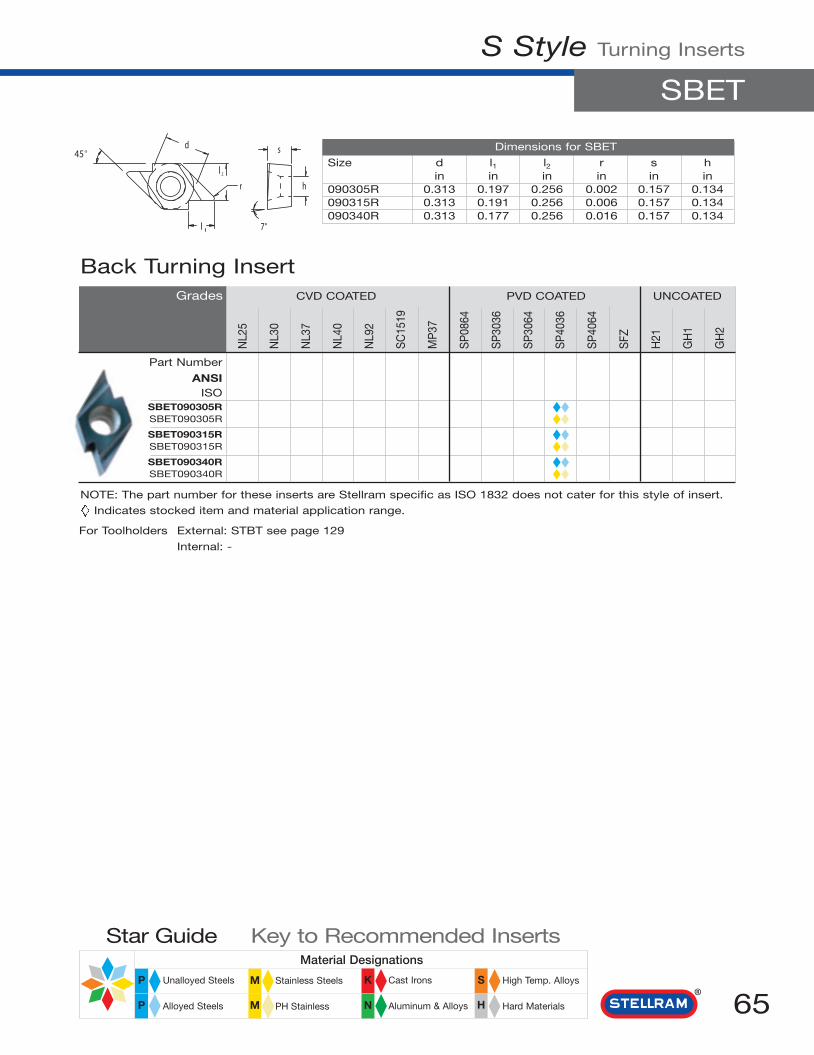
N
Material Designations
High Temp. Alloys
Hard Materials
Cast Irons
Aluminum & Alloys
Stainless Steels
PH Stainless
Unalloyed Steels
Alloyed Steels
Star Guide Key to Recommended Inserts
P M K S
HMP
S Style Turning Inserts
SBET
65
NL2
5
NL3
0
NL3
7
NL4
0
NL9
2
SC
1519
MP
37
SP
0864
SP
3036
SP
3064
SP
4036
SP
4064
SFZ
H21
GH
1
GH
2
Dimensions for SBET
Size d l1 l2 r s hin in in in in in
090305R 0.313 0.197 0.256 0.002 0.157 0.134090315R 0.313 0.191 0.256 0.006 0.157 0.134090340R 0.313 0.177 0.256 0.016 0.157 0.134
Back Turning InsertGrades CVD COATED PVD COATED UNCOATED
Part Number
ANSIISO
SBET090305R ◆◆SBET090305R ◆◆SBET090315R ◆◆SBET090315R ◆◆SBET090340R ◆◆SBET090340R ◆◆
NOTE: The part number for these inserts are Stellram specific as ISO 1832 does not cater for this style of insert.
Indicates stocked item and material application range.
For Toolholders External: STBT see page 129
Internal: -
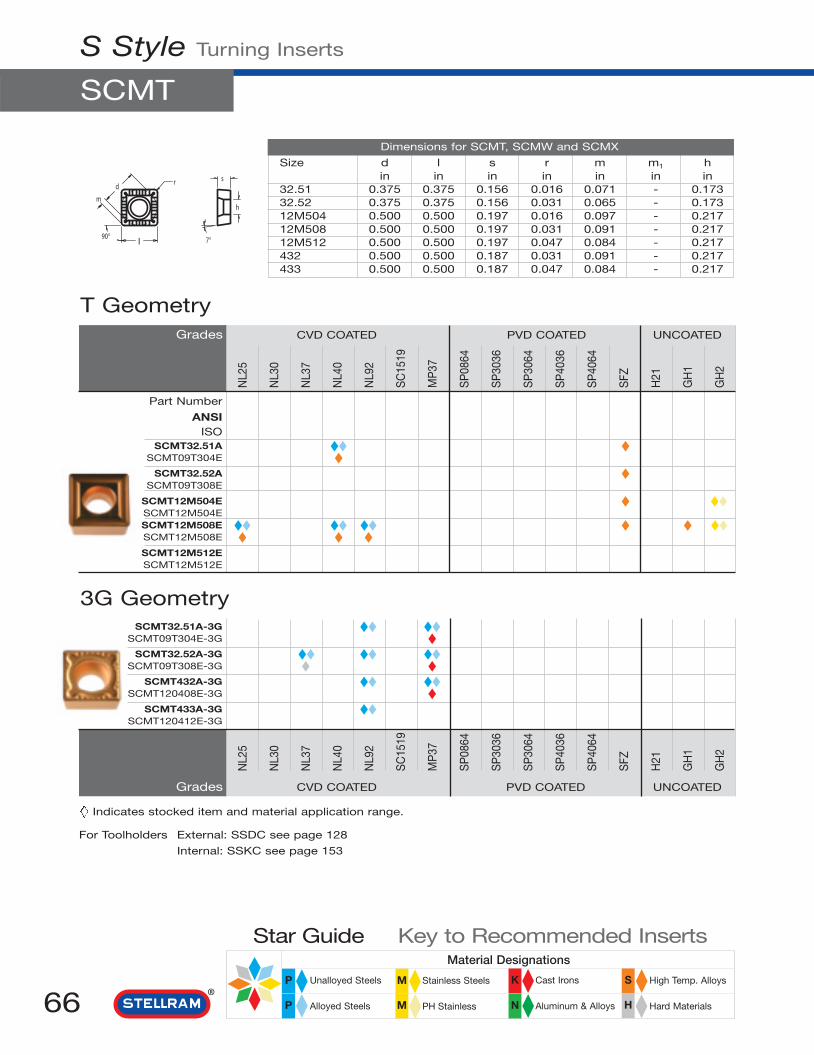
N
Material Designations
High Temp. Alloys
Hard Materials
Cast Irons
Aluminum & Alloys
Stainless Steels
PH Stainless
Unalloyed Steels
Alloyed Steels
Star Guide Key to Recommended Inserts
P M K S
HMP
SCMT32.51A-3G ◆◆ ◆◆SCMT09T304E-3G ◆
SCMT32.52A-3G ◆◆ ◆◆ ◆◆SCMT09T308E-3G ◆◆ ◆
SCMT432A-3G ◆◆ ◆◆SCMT120408E-3G ◆ ◆
SCMT433A-3G ◆◆SCMT120412E-3G
Grades CVD COATED PVD COATED UNCOATED
3G Geometry
NL2
5
NL3
0
NL3
7
NL4
0
NL9
2
SC
1519
MP
37
SP
0864
SP
3036
SP
3064
SP
4036
SP
4064
SFZ
H21
GH
1
GH
2
S Style Turning Inserts
SCMT
66
NL2
5
NL3
0
NL3
7
NL4
0
NL9
2
SC
1519
MP
37
SP
0864
SP
3036
SP
3064
SP
4036
SP
4064
SFZ
H21
GH
1
GH
2
Dimensions for SCMT, SCMW and SCMX
Size d l s r m m1 hin in in in in in in
32.51 0.375 0.375 0.156 0.016 0.071 - 0.17332.52 0.375 0.375 0.156 0.031 0.065 - 0.17312M504 0.500 0.500 0.197 0.016 0.097 - 0.21712M508 0.500 0.500 0.197 0.031 0.091 - 0.21712M512 0.500 0.500 0.197 0.047 0.084 - 0.217432 0.500 0.500 0.187 0.031 0.091 - 0.217433 0.500 0.500 0.187 0.047 0.084 - 0.217
T GeometryGrades CVD COATED PVD COATED UNCOATED
Part Number
ANSIISO
SCMT32.51A ◆◆ ◆SCMT09T304E ◆ ◆
SCMT32.52A ◆SCMT09T308E
SCMT12M504E ◆ ◆◆SCMT12M504ESCMT12M508E ◆◆ ◆◆ ◆◆ ◆ ◆ ◆◆SCMT12M508E ◆ ◆ ◆SCMT12M512ESCMT12M512E
Indicates stocked item and material application range.
For Toolholders External: SSDC see page 128
Internal: SSKC see page 153

N
Material Designations
High Temp. Alloys
Hard Materials
Cast Irons
Aluminum & Alloys
Stainless Steels
PH Stainless
Unalloyed Steels
Alloyed Steels
Star Guide Key to Recommended Inserts
P M K S
HMP
S Style Turning Inserts
SCMT, SCMW, SCMX
67
NL2
5
NL3
0
NL3
7
NL4
0
NL9
2
SC
1519
MP
37
SP
0864
SP
3036
SP
3064
SP
4036
SP
4064
SFZ
H21
GH
1
GH
2
73 GeometryGrades CVD COATED PVD COATED UNCOATED
Part Number
ANSIISO
SCMT32.51A-73 ◆◆ ◆◆SCMT09T304E-73 ◆◆ ◆◆
SCMT32.52A-73 ◆◆ ◆◆ ◆◆SCMT09T308E-73 ◆◆ ◆◆ ◆◆
SCMT12M504E-73 ◆◆ ◆◆SCMT12M504E-73 ◆◆ ◆◆SCMT12M508E-73 ◆◆ ◆◆ ◆◆ ◆◆SCMT12M508E-73 ◆◆ ◆◆ ◆◆ ◆◆
SCMW32.51A ◆SCMW09T304E ◆
SCMW32.52A ◆SCMW09T308E ◆
SCMW12M508E ◆SCMW12M508E ◆
Flat Top
SCMX32.51L ◆◆SCMX09T304FL ◆◆
SCMX32.51R ◆◆SCMX09T304FR ◆◆
SCMX32.52L ◆◆SCMX09T308FL ◆◆
SCMX32.52R ◆◆SCMX09T308FR ◆◆
SCMX12M508FL ◆◆SCMX12M508FL ◆◆
SCMX12M508FR ◆◆SCMX12M508FR ◆◆SCMX12M512ER ◆◆SCMX12M512ER ◆◆
Grades CVD COATED PVD COATED UNCOATED
X Geometry
NL2
5
NL3
0
NL3
7
NL4
0
NL9
2
SC
1519
MP
37
SP
0864
SP
3036
SP
3064
SP
4036
SP
4064
SFZ
H21
GH
1
GH
2
Indicates stocked item and material application range.
For Toolholders External: SSDC see page 128
Internal: SSKC see page 153

N
Material Designations
High Temp. Alloys
Hard Materials
Cast Irons
Aluminum & Alloys
Stainless Steels
PH Stainless
Unalloyed Steels
Alloyed Steels
Star Guide Key to Recommended Inserts
P M K S
HMP
S Style Turning Inserts
SNG, SNU
68
NL2
5
NL3
0
NL3
7
NL4
0
NL9
2
SC
1519
MP
37
SP
0864
SP
3036
SP
3064
SP
4036
SP
4064
SFZ
H21
GH
1
GH
2
Dimensions for SNG and SNU
Size d l s r m m1 hin in in in in in in
433 0.500 0.500 0.188 0.047 0.084 - -438 0.500 0.500 0.188 0.125 0.051 - -438 0.500 0.500 0.188 0.125 0.051 - -8512 1.000 1.000 0.312 0.189 0.128 - -
Flat TopGrades CVD COATED PVD COATED UNCOATED
Part Number
ANSIISO
SNG433A ◆SNGN120412E ◆
SNG438A ◆SNGN120432E
Flat Top
Grades CVD COATED PVD COATED UNCOATED
NL2
5
NL3
0
NL3
7
NL4
0
NL9
2
SC
1519
MP
37
SP
0864
SP
3036
SP
3064
SP
4036
SP
4064
SFZ
H21
GH
1
GH
2
SNU433A ◆SNUN120412E ◆
SNU643A ◆ ◆SNUN190412E
SNU8512TA ◆ ◆SNUN250748E
Indicates stocked item and material application range.
For Toolholders External: MSDNN, MSKN, MSRN, MSSN see pages 107 - 110
Internal: MSKN see page 143

N
Material Designations
High Temp. Alloys
Hard Materials
Cast Irons
Aluminum & Alloys
Stainless Steels
PH Stainless
Unalloyed Steels
Alloyed Steels
Star Guide Key to Recommended Inserts
P M K S
HMP
S Style Turning Inserts
SNMA
69
NL2
5
NL3
0
NL3
7
NL4
0
NL9
2
SC
1519
MP
37
SP
0864
SP
3036
SP
3064
SP
4036
SP
4064
SFZ
H21
GH
1
GH
2
Dimensions for SNMA, SNMG, SNMM
Size d l s r m m1 hin in in in in in in
322 0.375 0.375 0.125 0.031 0.065 - 0.150431 0.500 0.500 0.188 0.016 0.097 - 0.203432 0.500 0.500 0.188 0.031 0.091 - 0.203433 0.500 0.500 0.188 0.047 0.084 - 0.203434 0.500 0.500 0.188 0.063 0.078 - 0.203438 0.500 0.500 0.188 0.125 0.051 - 0.203542 0.625 0.625 0.250 0.031 0.116 - 0.250543 0.625 0.625 0.250 0.047 0.110 - 0.250544 0.625 0.625 0.250 0.063 0.104 - 0.250643 0.750 0.750 0.250 0.047 0.136 - 0.312644 0.750 0.750 0.250 0.063 0.129 - 0.312648 0.750 0.750 0.250 0.125 0.104 - 0.312866 1.000 1.000 0.375 0.940 0.168 - 0.359
Flat TopGrades CVD COATED PVD COATED UNCOATED
Part Number
ANSIISO
SNMA432A ◆SNMA120408E ◆
SNMA433A ◆SNMA120412E ◆
SNMA644A ◆ ◆ ◆SNMA190616E ◆
SNMA648B ◆ ◆SNMA190632E ◆
NL2
5
NL3
0
NL3
7
NL4
0
NL9
2
SC
1519
MP
37
SP
0864
SP
3036
SP
3064
SP
4036
SP
4064
SFZ
H21
GH
1
GH
2
Grades CVD COATED PVD COATED UNCOATED
Indicates stocked item and material application range.
For Toolholders External: MSDNN, MSKN, MSRN, MSSN see pages 107 - 110
Internal: MSKN see page 143

N
Material Designations
High Temp. Alloys
Hard Materials
Cast Irons
Aluminum & Alloys
Stainless Steels
PH Stainless
Unalloyed Steels
Alloyed Steels
Star Guide Key to Recommended Inserts
P M K S
HMP
SNMG432A-2N ◆◆ ◆◆ ◆◆ ◆◆SNMG120408E-2N ◆◆ ◆ ◆◆ ◆
SNMG433A-2N ◆◆ ◆◆SNMG120412E-2N ◆ ◆◆
SNMG543A-2N ◆◆ ◆◆ ◆◆SNMG150612E-2N ◆◆ ◆ ◆◆
SNMG643A-2N ◆◆ ◆◆SNMG190612E-2N ◆◆ ◆◆
SNMG644A-2N ◆ ◆◆SNMG190616E-2N ◆◆
Grades CVD COATED PVD COATED UNCOATED
2N Geometry
NL2
5
NL3
0
NL3
7
NL4
0
NL9
2
SC
1519
MP
37
SP
0864
SP
3036
SP
3064
SP
4036
SP
4064
SFZ
H21
GH
1
GH
2
2B GeometryGrades CVD COATED PVD COATED UNCOATED
Part Number
ANSIISO
SNMG432A-2BSNMG120408E-2B ◆
S Style Turning Inserts
SNMG
70
SNMG322A-3G ◆◆ ◆◆SNMG090308E-3G ◆
SNMG432A-3G ◆◆ ◆◆ ◆◆SNMG120408E-3G ◆
SNMG433A-3G ◆◆ ◆◆SNMG120412E-3G ◆
SNMG434A-3G ◆◆SNMG120416E-3G ◆
SNMG643A-3G ◆◆SNMG190612E-3G ◆
SNMG644A-3G ◆SNMG190616E-3G
3G Geometry
NL2
5
NL3
0
NL3
7
NL4
0
NL9
2
SC
1519
MP
37
SP
0864
SP
3036
SP
3064
SP
4036
SP
4064
SFZ
H21
GH
1
GH
2
Indicates stocked item and material application range.
For Toolholders External: MSDNN, MSKN, MSRN, MSSN see pages 107 - 110
Internal: MSKN see page 143

N
Material Designations
High Temp. Alloys
Hard Materials
Cast Irons
Aluminum & Alloys
Stainless Steels
PH Stainless
Unalloyed Steels
Alloyed Steels
Star Guide Key to Recommended Inserts
P M K S
HMP
S Style Turning Inserts
SNMG
71
NL2
5
NL3
0
NL3
7
NL4
0
NL9
2
SC
1519
MP
37
SP
0864
SP
3036
SP
3064
SP
4036
SP
4064
SFZ
H21
GH
1
GH
2
3J GeometryGrades CVD COATED PVD COATED UNCOATED
Part Number
ANSIISO
SNMG432A-3J ◆◆ ◆◆ ◆◆ ◆◆SNMG120408E-3J ◆ ◆ ◆ ◆
SNMG433A-3J ◆◆ ◆◆SNMG120412E-3J ◆ ◆
SNMG543A-3J ◆◆ ◆◆SNMG150612E-3J ◆ ◆
SNMG644A-3J ◆◆SNMG190616E-3J ◆
SNMG322A-4T ◆◆SNMG090308E-4T ◆◆
SNMG431A-4T ◆◆ ◆SNMG120404E-4T ◆◆ ◆
SNMG432A-4T ◆◆ ◆◆ ◆◆ ◆◆ ◆◆ ◆◆ ◆◆SNMG120408E-4T ◆◆ ◆◆ ◆ ◆ ◆ ◆ ◆
SNMG433A-4T ◆◆ ◆◆ ◆◆ ◆◆ ◆◆SNMG120412E-4T ◆◆ ◆◆ ◆ ◆ ◆
SNMG434A-4T ◆◆SNMG120416E-4T ◆◆
SNMG542A-4T ◆◆SNMG150608E-4T ◆◆
SNMG543A-4T ◆◆ ◆◆ ◆◆ ◆◆ ◆◆SNMG150612E-4T ◆◆ ◆◆ ◆ ◆ ◆
SNMG544A-4T ◆◆SNMG150616E-4T ◆
Grades CVD COATED PVD COATED UNCOATED
4T Geometry
NL2
5
NL3
0
NL3
7
NL4
0
NL9
2
SC
1519
MP
37
SP
0864
SP
3036
SP
3064
SP
4036
SP
4064
SFZ
H21
GH
1
GH
2
Indicates stocked item and material application range.
For Toolholders External: MSDNN, MSKN, MSRN, MSSN see pages 107 - 110
Internal: MSKN see page 143

Grades CVD COATED PVD COATED UNCOATED
NL2
5
NL3
0
NL3
7
NL4
0
NL9
2
SC
1519
MP
37
SP
0864
SP
3036
SP
3064
SP
4036
SP
4064
SFZ
H21
GH
1
GH
2
N
Material Designations
High Temp. Alloys
Hard Materials
Cast Irons
Aluminum & Alloys
Stainless Steels
PH Stainless
Unalloyed Steels
Alloyed Steels
Star Guide Key to Recommended Inserts
P M K S
HMP
SNMG432A-4U ◆SNMG120408E-4U ◆
SNMG433A-4U ◆SNMG120412E-4U
4U Geometry
NL2
5
NL3
0
NL3
7
NL4
0
NL9
2
SC
1519
MP
37
SP
0864
SP
3036
SP
3064
SP
4036
SP
4064
SFZ
H21
GH
1
GH
2
4T Geometry continued
Grades CVD COATED PVD COATED UNCOATED
Part Number
ANSIISO
SNMG643A-4T ◆◆ ◆◆ ◆◆ ◆◆ ◆◆SNMG190612E-4T ◆◆ ◆◆ ◆ ◆ ◆
SNMG644A-4T ◆◆ ◆◆ ◆◆ ◆◆ ◆◆ ◆◆SNMG190616E-4T ◆◆ ◆◆ ◆ ◆ ◆ ◆
SNMG866B-4T ◆◆ ◆◆ ◆◆ ◆◆SNMG250924E-4T ◆◆ ◆ ◆ ◆
S Style Turning Inserts
SNMG, SNMM
72
4M Geometry
Indicates stocked item and material application range.
For Toolholders External: MSDNN, MSKN, MSRN, MSSN see pages 107 - 110
Internal: MSKN see page 143
SNMM432A-4M ◆◆ ◆◆SNMM120408E-4M ◆◆ ◆◆
SNMM643A-4M ◆◆ ◆◆SNMM190612E-4M ◆◆ ◆◆
SNMM644A-4M ◆◆ ◆◆ ◆◆SNMM190612E-4M ◆◆ ◆◆
SNMM866B-4M ◆◆ ◆◆ ◆◆SNMM250924E-4M ◆◆ ◆◆

N
Material Designations
High Temp. Alloys
Hard Materials
Cast Irons
Aluminum & Alloys
Stainless Steels
PH Stainless
Unalloyed Steels
Alloyed Steels
Star Guide Key to Recommended Inserts
P M K S
HMP
S Style Turning Inserts
SPG, SPU
73
NL2
5
NL3
0
NL3
7
NL4
0
NL9
2
SC
1519
MP
37
SP
0864
SP
3036
SP
3064
SP
4036
SP
4064
SFZ
H21
GH
1
GH
2
Dimensions for SPG and SPU
Size d l s r m m1 hin in in in in in in
422 0.500 0.500 0.125 0.031 0.091 - -423 0.500 0.500 0.125 0.047 0.084 - -433 0.500 0.500 0.188 0.047 0.084 - -633 0.750 0.750 0.188 0.047 0.136 - 0.359643 0.750 0.750 0.250 0.047 0.136 - -644 0.750 0.750 0.250 0.063 0.129 - -
Flat TopGrades CVD COATED PVD COATED UNCOATED
Part Number
ANSIISO
SPG422A ◆◆SPGN120308E ◆ ◆
SPG422 ◆ ◆SPGN120308F ◆
SPG423 ◆ ◆SPGN120312F ◆
SPG433A ◆ ◆SPGN120412E ◆ ◆
SPG643A ◆ ◆SPGN190412E ◆ ◆
SPG643 ◆ ◆SPGN190412F ◆
SPG644 ◆ ◆SPGN190416F
Grades CVD COATED PVD COATED UNCOATED
Flat Top
NL2
5
NL3
0
NL3
7
NL4
0
NL9
2
SC
1519
MP
37
SP
0864
SP
3036
SP
3064
SP
4036
SP
4064
SFZ
H21
GH
1
GH
2
SPU422A ◆ ◆SPUN120308E ◆
SPU422 ◆SPUN120308F ◆
SPU633A ◆ ◆SPUN190412E ◆
SPU633 ◆ ◆SPUN190412F
Indicates stocked item and material application range.
For Toolholders External: -
Internal: -

N
Material Designations
High Temp. Alloys
Hard Materials
Cast Irons
Aluminum & Alloys
Stainless Steels
PH Stainless
Unalloyed Steels
Alloyed Steels
Star Guide Key to Recommended Inserts
P M K S
HMP
T Style Turning Inserts
TCMT
74
NL2
5
NL3
0
NL3
7
NL4
0
NL9
2
SC
1519
MP
37
SP
0864
SP
3036
SP
3064
SP
4036
SP
4064
SFZ
H21
GH
1
GH
2
Dimensions for TCMT, TCMW and TCMX
Size d l s r m m1 hin in in in in in in
21.50.5 0.250 0.433 0.094 0.008 0.367 - 0.11021.51 0.250 0.433 0.094 0.016 0.359 - 0.11021.52 0.250 0.433 0.094 0.031 0.344 - 0.11032.51 0.375 0.650 0.156 0.016 0.547 - 0.17332.52 0.375 0.650 0.156 0.031 0.531 - 0.17322M504 0.500 0.866 0.197 0.016 0.734 - 0.21722M508 0.500 0.866 0.197 0.031 0.719 - 0.21722M512 0.500 0.866 0.197 0.047 0.703 - 0.217
T GeometryGrades CVD COATED PVD COATED UNCOATED
Part Number
ANSIISO
TCMT32.51A ◆◆ ◆◆ ◆◆TCMT16T304E ◆ ◆ ◆
TCMT32.52A ◆◆ ◆◆ ◆◆ ◆◆ ◆◆TCMT16T308E ◆ ◆ ◆ ◆
TCMT22M504E ◆◆TCMT22M504E ◆◆TCMT22M508E ◆◆TCMT22M508E ◆TCMT22M512ETCMT22M512E
3G GeometryTCMT21.51A-3G ◆◆ ◆◆
TCMT110204E-3G ◆ ◆TCMT21.52A-3G ◆◆ ◆◆
TCMT110208E-3G ◆ ◆TCMT32.51A-3G ◆◆ ◆◆
TCMT16T304E-3G ◆ ◆TCMT32.52A-3G ◆◆ ◆◆ ◆◆
TCMT16T308E-3G ◆
Grades CVD COATED PVD COATED UNCOATED
NL2
5
NL3
0
NL3
7
NL4
0
NL9
2
SC
1519
MP
37
SP
0864
SP
3036
SP
3064
SP
4036
SP
4064
SFZ
H21
GH
1
GH
2
Indicates stocked item and material application range.
For Toolholders External: STGC see page 130
Internal: STUC see page 154

N
Material Designations
High Temp. Alloys
Hard Materials
Cast Irons
Aluminum & Alloys
Stainless Steels
PH Stainless
Unalloyed Steels
Alloyed Steels
Star Guide Key to Recommended Inserts
P M K S
HMP
T Style Turning Inserts
TCMT, TCMW, TCMX
75
NL2
5
NL3
0
NL3
7
NL4
0
NL9
2
SC
1519
MP
37
SP
0864
SP
3036
SP
3064
SP
4036
SP
4064
SFZ
H21
GH
1
GH
2
73 GeometryGrades CVD COATED PVD COATED UNCOATED
Part Number
ANSIISO
TCMT21.50.5A-73 ◆◆TCMT110202E-73 ◆◆
TCMT21.51A-73 ◆◆ ◆◆TCMT110204E-73 ◆◆ ◆◆
TCMT32.51A-73 ◆◆ ◆◆ ◆◆ ◆◆TCMT16T304E-73 ◆◆ ◆◆ ◆◆
TCMT32.52A-73 ◆◆ ◆◆ ◆◆ ◆◆TCMT16T308E-73 ◆◆ ◆◆ ◆◆
TCMT22M508E-73 ◆◆TCMT22M508E-73 ◆◆
TCMW32.51A ◆TCMW16T304E ◆
TCMW32.52A ◆◆TCMW16T308E ◆
TCMW22M508E ◆TCMW22M508E ◆
Grades CVD COATED PVD COATED UNCOATED
Flat Top
NL2
5
NL3
0
NL3
7
NL4
0
NL9
2
SC
1519
MP
37
SP
0864
SP
3036
SP
3064
SP
4036
SP
4064
SFZ
H21
GH
1
GH
2
TCMX32.51ALTCMX16T304EL
TCMX32.51ARTCMX16T304ER
TCMX32.51L ◆◆TCMX16T304FL ◆◆
TCMX32.51R ◆◆TCMX16T304FR ◆◆
TCMX32.52L ◆◆TCMX16T308FL ◆◆
TCMX32.52R ◆◆TCMX16T308FR ◆◆
X Geometry
TCMX32.51-15TCMX16T304F-15
15 Geometry
For ToolholdersExternal: STGC see page 130Internal: STUC see page 154

N
Material Designations
High Temp. Alloys
Hard Materials
Cast Irons
Aluminum & Alloys
Stainless Steels
PH Stainless
Unalloyed Steels
Alloyed Steels
Star Guide Key to Recommended Inserts
P M K S
HMP
T Style Turning Inserts
TNG
76
NL2
5
NL3
0
NL3
7
NL4
0
NL9
2
SC
1519
MP
37
SP
0864
SP
3036
SP
3064
SP
4036
SP
4064
SFZ
H21
GH
1
GH
2
Dimensions for TNG
Size d l s r m m1 hin in in in in in in
322 0.375 0.650 0.125 0.031 0.531 - -
Flat TopGrades CVD COATED PVD COATED UNCOATED
Part Number
ANSIISO
TNG322A ◆TNGN160308E ◆
Indicates stocked item and material application range.
For Toolholders External: MTENN, MTFN, MTJN see pages 111 - 113
Internal: -
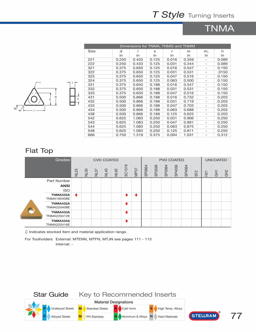
N
Material Designations
High Temp. Alloys
Hard Materials
Cast Irons
Aluminum & Alloys
Stainless Steels
PH Stainless
Unalloyed Steels
Alloyed Steels
Star Guide Key to Recommended Inserts
P M K S
HMP
T Style Turning Inserts
TNMA
77
NL2
5
NL3
0
NL3
7
NL4
0
NL9
2
SC
1519
MP
37
SP
0864
SP
3036
SP
3064
SP
4036
SP
4064
SFZ
H21
GH
1
GH
2
Dimensions for TNMA, TNMG and TNMM
Size d l s r m m1 hin in in in in in in
221 0.250 0.433 0.125 0.016 0.359 - 0.089222 0.250 0.433 0.125 0.031 0.344 - 0.089321 0.375 0.650 0.125 0.016 0.547 - 0.150322 0.375 0.650 0.125 0.031 0.531 - .0150323 0.375 0.650 0.125 0.047 0.516 - 0.150324 0.375 0.650 0.125 0.063 0.500 - 0.150331 0.375 0.650 0.188 0.016 0.547 - 0.150332 0.375 0.650 0.188 0.031 0.531 - 0.150333 0.375 0.650 0.188 0.047 0.516 - 0.150431 0.500 0.866 0.188 0.016 0.732 - 0.203432 0.500 0.866 0.188 0.031 0.719 - 0.203433 0.500 0.866 0.188 0.047 0.703 - 0.203434 0.500 0.866 0.188 0.063 0.688 - 0.203438 0.500 0.866 0.188 0.125 0.625 - 0.203542 0.625 1.083 0.250 0.031 0.906 - 0.250543 0.625 1.083 0.250 0.047 0.891 - 0.250544 0.625 1.083 0.250 0.063 0.875 - 0.250548 0.625 1.083 0.250 0.125 0.811 - 0.250666 0.750 1.319 0.375 0.094 1.031 - 0.312
Flat TopGrades CVD COATED PVD COATED UNCOATED
Part Number
ANSIISO
TNMA332A ◆ ◆ ◆TNMA160408E ◆
TNMA432A ◆TNMA220408E ◆
TNMA433A ◆TNMA220412E ◆
TNMA434A ◆TNMA220416E
Indicates stocked item and material application range.
For Toolholders External: MTENN, MTFN, MTJN see pages 111 - 113
Internal: -

N
Material Designations
High Temp. Alloys
Hard Materials
Cast Irons
Aluminum & Alloys
Stainless Steels
PH Stainless
Unalloyed Steels
Alloyed Steels
Star Guide Key to Recommended Inserts
P M K S
HMP
NL2
5
NL3
0
NL3
7
NL4
0
NL9
2
SC
1519
MP
37
SP
0864
SP
3036
SP
3064
SP
4036
SP
4064
SFZ
H21
GH
1
GH
2
1A GeometryGrades CVD COATED PVD COATED UNCOATED
Part Number
ANSIISO
TNMG331A-1A ◆◆TNMG160404E-1A ◆
TNMG332A-1A ◆◆ ◆◆TNMG160408E-1A ◆ ◆
T Style Turning Inserts
TNMG
78
TNMG331A-2B ◆◆TNMG160404E-2B ◆
TNMG332A-2B ◆◆TNMG160408E-2B
TNMG432A-2B ◆◆ ◆◆TNMG220408E-2B
2B Geometry
Grades CVD COATED PVD COATED UNCOATED
NL2
5
NL3
0
NL3
7
NL4
0
NL9
2
SC
1519
MP
37
SP
0864
SP
3036
SP
3064
SP
4036
SP
4064
SFZ
H21
GH
1
GH
2
Indicates stocked item and material application range.
For Toolholders External: MTENN, MTFN, MTJN see pages 111 - 113
Internal: -

N
Material Designations
High Temp. Alloys
Hard Materials
Cast Irons
Aluminum & Alloys
Stainless Steels
PH Stainless
Unalloyed Steels
Alloyed Steels
Star Guide Key to Recommended Inserts
P M K S
HMP
T Style Turning Inserts
TNMG
79
NL2
5
NL3
0
NL3
7
NL4
0
NL9
2
SC
1519
MP
37
SP
0864
SP
3036
SP
3064
SP
4036
SP
4064
SFZ
H21
GH
1
GH
2
2N GeometryGrades CVD COATED PVD COATED UNCOATED
Part Number
ANSIISO
TNMG331A-2N ◆◆TNMG160404E-2N ◆◆
TNMG332A-2N ◆◆ ◆◆ ◆◆ ◆◆TNMG160408E-2N ◆◆ ◆◆ ◆ ◆◆
TNMG333A-2NTNMG160412E-2N
TNMG431A-2N ◆◆TNMG220404E-2N ◆◆
TNMG432A-2N ◆◆ ◆◆TNMG220408E-2N ◆◆ ◆◆
TNMG433A-2N ◆◆TNMG220412E-2N ◆◆
3G GeometryTNMG321A-3G ◆◆
TNMG160304E-3G ◆TNMG322A-3G ◆◆ ◆◆
TNMG160308E-3G ◆TNMG331A-3G ◆◆ ◆◆ ◆◆
TNMG160404E-3G ◆TNMG332A-3G ◆◆ ◆◆ ◆◆ ◆◆
TNMG160408E-3G ◆ ◆TNMG333A-3G
TNMG160412E-3G ◆TNMG431A-3G ◆◆ ◆◆
TNMG220404E-3G ◆TNMG432A-3G ◆◆ ◆◆ ◆◆
TNMG220408E-3GTNMG542A-3G ◆◆
TNMG270608E-3G ◆ ◆
NL2
5
NL3
0
NL3
7
NL4
0
NL9
2
SC
1519
MP
37
SP
0864
SP
3036
SP
3064
SP
4036
SP
4064
SFZ
H21
GH
1
GH
2
Grades CVD COATED PVD COATED UNCOATED
Indicates stocked item and material application range.
For Toolholders External: MTENN, MTFN, MTJN see pages 111 - 113
Internal: -

N
Material Designations
High Temp. Alloys
Hard Materials
Cast Irons
Aluminum & Alloys
Stainless Steels
PH Stainless
Unalloyed Steels
Alloyed Steels
Star Guide Key to Recommended Inserts
P M K S
HMP
NL2
5
NL3
0
NL3
7
NL4
0
NL9
2
SC
1519
MP
37
SP
0864
SP
3036
SP
3064
SP
4036
SP
4064
SFZ
H21
GH
1
GH
2
3J GeometryGrades CVD COATED PVD COATED UNCOATED
Part Number
ANSIISO
TNMG331A-3J ◆◆ ◆◆ ◆◆ ◆◆TNMG160404E-3J ◆ ◆ ◆ ◆
TNMG332A-3J ◆◆ ◆◆ ◆◆ ◆◆TNMG160408E-3J ◆ ◆ ◆ ◆
TNMG432A-3J ◆◆ ◆◆TNMG220408E-3J ◆ ◆
T Style Turning Inserts
TNMG
80
Indicates stocked item and material application range.
For Toolholders External: MTENN, MTFN, MTJN see pages 111 - 113
Internal: -

N
Material Designations
High Temp. Alloys
Hard Materials
Cast Irons
Aluminum & Alloys
Stainless Steels
PH Stainless
Unalloyed Steels
Alloyed Steels
Star Guide Key to Recommended Inserts
P M K S
HMP
T Style Turning Inserts
TNMG
81
NL2
5
NL3
0
NL3
7
NL4
0
NL9
2
SC
1519
MP
37
SP
0864
SP
3036
SP
3064
SP
4036
SP
4064
SFZ
H21
GH
1
GH
2
4T GeometryGrades CVD COATED PVD COATED UNCOATED
Part Number
ANSIISO
TNMG321A-4T ◆◆ ◆◆TNMG160304E-4T ◆◆ ◆
TNMG322A-4T ◆◆ ◆◆ ◆◆TNMG160308E-4T ◆◆ ◆◆ ◆
TNMG331A-4T ◆◆ ◆◆TNMG160404E-4T ◆◆ ◆
TNMG332A-4T ◆◆ ◆◆ ◆◆ ◆◆ ◆◆ ◆◆TNMG160408E-4T ◆◆ ◆◆ ◆ ◆ ◆ ◆
TNMG333A-4T ◆◆ ◆◆TNMG160412E-4T ◆◆ ◆
TNMG431A-4T ◆◆ ◆◆ ◆◆TNMG220404E-4T ◆◆ ◆ ◆
TNMG432A-4T ◆◆ ◆◆ ◆◆ ◆◆ ◆◆TNMG220408E-4T ◆◆ ◆◆ ◆ ◆ ◆
TNMG433A-4T ◆◆ ◆◆ ◆◆ ◆◆TNMG220412E-4T ◆◆ ◆ ◆ ◆
TNMG434A-4T ◆◆ ◆◆TNMG220416E-4T ◆◆ ◆
TNMG438A-4T ◆◆TNMG220432E-4T ◆◆
TNMG542A-4T ◆◆ ◆◆ ◆◆TNMG270608E-4T ◆◆ ◆◆ ◆
TNMG543A-4T ◆◆ ◆◆ ◆◆TNMG270612E-4T ◆◆ ◆ ◆
TNMG544A-4T ◆◆ ◆◆TNMG270616E-4T ◆◆ ◆
TNMG548A-4T ◆◆TNMG270632E-4T ◆◆
TNMG666B-4T ◆◆TNMG330924E-4T ◆
Grades CVD COATED PVD COATED UNCOATED
NL2
5
NL3
0
NL3
7
NL4
0
NL9
2
SC
1519
MP
37
SP
0864
SP
3036
SP
3064
SP
4036
SP
4064
SFZ
H21
GH
1
GH
2
Indicates stocked item and material application range.
For Toolholders External: MTENN, MTFN, MTJN see pages 111 - 113
Internal: -

N
Material Designations
High Temp. Alloys
Hard Materials
Cast Irons
Aluminum & Alloys
Stainless Steels
PH Stainless
Unalloyed Steels
Alloyed Steels
Star Guide Key to Recommended Inserts
P M K S
HMP
NL2
5
NL3
0
NL3
7
NL4
0
NL9
2
SC
1519
MP
37
SP
0864
SP
3036
SP
3064
SP
4036
SP
4064
SFZ
H21
GH
1
GH
2
4U GeometryGrades CVD COATED PVD COATED UNCOATED
Part Number
ANSIISO
TNMG332A-4U ◆TNMG160408E-4U ◆
TNMG333A-4U ◆TNMG160412E-4U ◆
T Style Turning Inserts
TNMG, TNMM
82
Indicates stocked item and material application range.
For Toolholders External: MTENN, MTFN, MTJN see pages 111 - 113
Internal: -
Grades CVD COATED PVD COATED UNCOATED
4M Geometry
NL2
5
NL3
0
NL3
7
NL4
0
NL9
2
SC
1519
MP
37
SP
0864
SP
3036
SP
3064
SP
4036
SP
4064
SFZ
H21
GH
1
GH
2
TNMM433A-4M ◆◆TNMM220412E-4M ◆◆

T Style Turning Inserts
TPG
Grades CVD COATED PVD COATED UNCOATED
2C Geometry
83
NL2
5
NL3
0
NL3
7
NL4
0
NL9
2
SC
1519
MP
37
SP
0864
SP
3036
SP
3064
SP
4036
SP
4064
SFZ
H21
GH
1
GH
2
TPGH221A-2C ◆◆ ◆◆TPGH110304E-2C ◆ ◆
TPGH222A-2C ◆◆ ◆◆TPGH110308E-2C ◆ ◆
TPGH321A-2C ◆◆ ◆◆TPGH160304E-2C ◆ ◆
TPGH322A-2C ◆◆ ◆◆TPGH160308E-2C ◆ ◆
13,9
3,2
s
d h8
l
60º
11º
11,6m
r
Dimensions for TPG and TPU
Size d l s r m m1 hin in in in in in in
321 0.375 0.650 0.125 0.016 0.547 - -322 0.375 0.650 0.125 0.031 0.531 - -323 0.375 0.650 0.125 0.047 0.516 - -431 0.500 0.866 0.188 0.016 0.734 - -432 0.500 0.866 0.188 0.031 0.719 - -433 0.500 0.866 0.188 0.047 0.703 - -434 0.500 0.866 0.188 0.063 0.688 - -
NL2
5
NL3
0
NL3
7
NL4
0
NL9
2
SC
1519
MP
37
SP
0864
SP
3036
SP
3064
SP
4036
SP
4064
SFZ
H21
GH
1
GH
2
Flat TopGrades CVD COATED PVD COATED UNCOATED
Part Number
ANSIISO
TPG221A ◆ ◆TPGN110304E ◆
TPG321A ◆ ◆ ◆TPGN160304E ◆ ◆
TPG321 ◆ ◆TPGN160304F ◆
TPG322A ◆ ◆ ◆TPGN160308E ◆
TPG322 ◆ ◆TPGN160308F ◆
TPG323A ◆ ◆ ◆TPGN160312E ◆
TPG431A ◆ ◆ ◆TPGN220404E ◆
TPG432A ◆ ◆TPGN220408E ◆
TPG432 ◆ ◆TPGN220408F ◆
TPG433A ◆ ◆TPGN220412E ◆
TPG433 ◆ ◆TPGN220412F ◆
TPG434 ◆ ◆TPGN220416F
Indicates stocked item and material application range.
For Toolholders: External: STGP see page 131
Internal: STUP see page 155

N
Material Designations
High Temp. Alloys
Hard Materials
Cast Irons
Aluminum & Alloys
Stainless Steels
PH Stainless
Unalloyed Steels
Alloyed Steels
Star Guide Key to Recommended Inserts
P M K S
HMP
T Style Turning Inserts
TPU
84
NL2
5
NL3
0
NL3
7
NL4
0
NL9
2
SC
1519
MP
37
SP
0864
SP
3036
SP
3064
SP
4036
SP
4064
SFZ
H21
GH
1
GH
2
Flat TopGrades CVD COATED PVD COATED UNCOATED
Part Number
ANSIISO
TPU321A ◆ ◆ ◆TPUN160304E ◆ ◆
TPU321 ◆TPUN160304F ◆
TPU322A ◆ ◆ ◆TPUN160308E ◆ ◆
TPU432A ◆ ◆ ◆TPUN220408E ◆ ◆
TPU433A ◆ ◆TPUN220412E
Indicates stocked item and material application range.
For Toolholders: External: STGP see page 131
Internal: STUP see page 155

N
Material Designations
High Temp. Alloys
Hard Materials
Cast Irons
Aluminum & Alloys
Stainless Steels
PH Stainless
Unalloyed Steels
Alloyed Steels
Star Guide Key to Recommended Inserts
P M K S
HMP
V Style Turning Inserts
VBMT
85
º
º
Dimensions for VBMT
Size d l s r m m1 hin in in in in in in
330.5 0.375 0.654 0.188 0.008 0.417 - 0.173331 0.375 0.654 0.188 0.016 0.400 - 0.173332 0.375 0.654 0.188 0.031 0.363 - 0.173
NL2
5
NL3
0
NL3
7
NL4
0
NL9
2
SC
1519
MP
37
SP
0864
SP
3036
SP
3064
SP
4036
SP
4064
SFZ
H21
GH
1
GH
2
3G GeometryGrades CVD COATED PVD COATED UNCOATED
Part Number
ANSIISO
VBMT330.5A-3G ◆◆VBMT160402E-3G ◆
VBMT331A-3G ◆◆ ◆◆ ◆◆VBMT160404E-3G ◆ ◆
VBMT332A-3G ◆◆ ◆◆ ◆◆VBMT160408E-3G ◆ ◆
Indicates stocked item and material application range.
For Toolholders: External: SVJB see page 133
Internal: -

N
Material Designations
High Temp. Alloys
Hard Materials
Cast Irons
Aluminum & Alloys
Stainless Steels
PH Stainless
Unalloyed Steels
Alloyed Steels
Star Guide Key to Recommended Inserts
P M K S
HMP
V Style Turning Inserts
VCGT
86
NL2
5
NL3
0
NL3
7
NL4
0
NL9
2
SC
1519
MP
37
SP
0864
SP
3036
SP
3064
SP
4036
SP
4064
SFZ
H21
GH
1
GH
2
Dimensions for VCGT, VCGW, VCMT and VCMW
Size d l s r m m1 hin in in in in in in
130301 0.313 0.543 0.125 0.003 0.354 - 0.142130302 0.313 0.543 0.125 0.008 0.345 - 0.142130304 0.313 0.543 0.125 0.016 0.327 - 0.142130308 0.313 0.543 0.125 0.031 0.291 - 0.142331 0.375 0.634 0.187 0.016 0.400 - 0.173332 0.375 0.634 0.187 0.031 0.363 - 0.173
M GeometryGrades CVD COATED PVD COATED UNCOATED
Part Number
ANSIISO
VCGT130301F-M ◆◆ ◆◆VCGT130301F-M ◆VCGT130302E-M ◆◆ ◆◆ ◆◆ ◆◆VCGT130302E-M ◆ ◆ ◆VCGT130304E-M ◆◆ ◆◆ ◆◆ ◆◆VCGT130304E-M ◆ ◆ ◆
Grades CVD COATED PVD COATED UNCOATED
62 Geometry
VCGT130301E-62 ◆◆VCGT130301E-62 ◆◆VCGT130302E-62 ◆◆ ◆◆VCGT130302E-62 ◆◆ ◆◆VCGT130304E-62 ◆◆VCGT130304E-62 ◆◆
Indicates stocked item and material application range.
For Toolholders: External: SVAC, SVVC see pages 132 and 134
Internal: SVQC, SVUC see pages 156 - 157
NL2
5
NL3
0
NL3
7
NL4
0
NL9
2
SC
1519
MP
37
SP
0864
SP
3036
SP
3064
SP
4036
SP
4064
SFZ
H21
GH
1
GH
2

N
Material Designations
High Temp. Alloys
Hard Materials
Cast Irons
Aluminum & Alloys
Stainless Steels
PH Stainless
Unalloyed Steels
Alloyed Steels
Star Guide Key to Recommended Inserts
P M K S
HMP
V Style Turning Inserts
VCGT, VCGW, VCMT, VCMW
87
VCMW332A ◆VCMW160408E ◆
Grades CVD COATED PVD COATED UNCOATED
NL2
5
NL3
0
NL3
7
NL4
0
NL9
2
SC
1519
MP
37
SP
0864
SP
3036
SP
3064
SP
4036
SP
4064
SFZ
H21
GH
1
GH
2
64 GeometryGrades CVD COATED PVD COATED UNCOATED
Part Number
ANSIISO
VCGT332-64 ◆VCGT160408F-64
NL2
5
NL3
0
NL3
7
NL4
0
NL9
2
SC
1519
MP
37
SP
0864
SP
3036
SP
3064
SP
4036
SP
4064
SFZ
H21
GH
1
GH
2
VCGT130302F-66 ◆ ◆VCGT130302F-66 ◆VCGT130304F-66 ◆ ◆VCGT130304F-66 ◆VCGT130308F-66 ◆ ◆VCGT130308F-66
66 Geometry
VCGW130304F ◆VCGW130304F ◆
Flat Top
VCMT331A-M ◆◆ ◆◆ ◆◆VCMT160404E-M ◆ ◆
VCMT332A-M ◆◆ ◆◆ ◆◆ ◆◆VCMT160408E-M ◆ ◆ ◆
M Geometry
Flat Top
Indicates stocked item and material application range.
For Toolholders: External: SVAC, SVVC see pages 132 and 134
Internal: SVQC, SVUC see pages 156 - 157

N
Material Designations
High Temp. Alloys
Hard Materials
Cast Irons
Aluminum & Alloys
Stainless Steels
PH Stainless
Unalloyed Steels
Alloyed Steels
Star Guide Key to Recommended Inserts
P M K S
HMP
V Style Turning Inserts
VNGP, VNMA
88
º
Dimensions for VNGG, VNMA and VNMG
Size d l s r m m1 hin in in in in in in
330.2 0.375 0.650 0.188 0.003 0.430 - 0.150330.5 0.375 0.650 0.188 0.008 0.420 - 0.150331 0.375 0.650 0.188 0.016 0.400 - 0.150332 0.375 0.650 0.188 0.031 0.363 - 0.150333 0.375 0.650 0.188 0.047 0.327 - 0.150431 0.500 0.866 0.188 0.016 0.545 - 0.203432 0.500 0.866 0.188 0.031 0.509 - 0.203
Grades CVD COATED PVD COATED UNCOATED
Flat Top
NL2
5
NL3
0
NL3
7
NL4
0
NL9
2
SC
1519
MP
37
SP
0864
SP
3036
SP
3064
SP
4036
SP
4064
SFZ
H21
GH
1
GH
2
VNMA432A ◆VNMA220408E ◆
Indicates stocked item and material application range.
For Toolholders: External: MVJN, MVPN, MVVNN see pages 114 - 116
Internal: MVUN see page 144
NL2
5
NL3
0
NL3
7
NL4
0
NL9
2
SC
1519
MP
37
SP
0864
SP
3036
SP
3064
SP
4036
SP
4064
SFZ
H21
GH
1
GH
2
3F GeometryGrades CVD COATED PVD COATED UNCOATED
Part Number
ANSIISO
VNGP330.2-3F ◆◆ ◆◆VNGG160401F-3F ◆◆ ◆
VNGP330.5-3F ◆◆ ◆◆VNGG160402F-3F ◆◆ ◆
VNGP331-3F ◆◆ ◆◆VNGG160404F-3F ◆◆ ◆
VNGP332-3F ◆◆ ◆◆VNGG160408F-3F ◆◆ ◆

Grades CVD COATED PVD COATED UNCOATED
NL2
5
NL3
0
NL3
7
NL4
0
NL9
2
SC
1519
MP
37
SP
0864
SP
3036
SP
3064
SP
4036
SP
4064
SFZ
H21
GH
1
GH
2
N
Material Designations
High Temp. Alloys
Hard Materials
Cast Irons
Aluminum & Alloys
Stainless Steels
PH Stainless
Unalloyed Steels
Alloyed Steels
Star Guide Key to Recommended Inserts
P M K S
HMP
V Style Turning Inserts
VNMG
89
NL2
5
NL3
0
NL3
7
NL4
0
NL9
2
SC
1519
MP
37
SP
0864
SP
3036
SP
3064
SP
4036
SP
4064
SFZ
H21
GH
1
GH
2
1A GeometryGrades CVD COATED PVD COATED UNCOATED
Part Number
ANSIISO
VNMG330.5A-1A ◆◆VNMG160402E-1A ◆
VNMG331A-1A ◆◆VNMG160404E-1A ◆
VNMG332A-1A ◆◆ ◆◆VNMG160408E-1A ◆
VNMG332A-2B ◆VNMG160408E-2B ◆
VNMG431A-2B ◆VNMG220404E-2B ◆
VNMG432A-2B ◆VNMG220408E-2B
2B Geometry
VNMG331A-2N ◆◆ ◆◆VNMG160404E-2N ◆◆ ◆◆
VNMG332A-2N ◆◆ ◆◆ ◆◆VNMG160408E-2N ◆◆ ◆◆ ◆◆
2N Geometry
Indicates stocked item and material application range.
For Toolholders: External: MVJN, MVPN, MVVNN see pages 114 - 116
Internal: MVUN see page 144

N
Material Designations
High Temp. Alloys
Hard Materials
Cast Irons
Aluminum & Alloys
Stainless Steels
PH Stainless
Unalloyed Steels
Alloyed Steels
Star Guide Key to Recommended Inserts
P M K S
HMP
V Style Turning Inserts
VNMG
90
NL2
5
NL3
0
NL3
7
NL4
0
NL9
2
SC
1519
MP
37
SP
0864
SP
3036
SP
3064
SP
4036
SP
4064
SFZ
H21
GH
1
GH
2
3G GeometryGrades CVD COATED PVD COATED UNCOATED
Part Number
ANSIISO
VNMG331A-3G ◆◆ ◆◆ ◆◆ ◆◆ ◆◆VNMG160404E-3G ◆ ◆
VNMG332A-3G ◆◆ ◆◆ ◆◆ ◆◆ ◆◆VNMG160408E-3G ◆ ◆
VNMG333A-3G ◆◆ ◆◆VNMG160412E-3G ◆ ◆
VNMG431A-3G ◆◆ ◆◆VNMG220404E-3G ◆
VNMG432A-3G ◆◆ ◆◆VNMG220408E-3G ◆
Grades CVD COATED PVD COATED UNCOATED
3J Geometry
NL2
5
NL3
0
NL3
7
NL4
0
NL9
2
SC
1519
MP
37
SP
0864
SP
3036
SP
3064
SP
4036
SP
4064
SFZ
H21
GH
1
GH
2
VNMG332A-3J ◆◆ ◆◆ ◆◆VNMG160408E-3J ◆ ◆ ◆
Indicates stocked item and material application range.
For Toolholders: External: MVJN, MVPN, MVVNN see pages 114 - 116
Internal: MVUN see page 144

N
Material Designations
High Temp. Alloys
Hard Materials
Cast Irons
Aluminum & Alloys
Stainless Steels
PH Stainless
Unalloyed Steels
Alloyed Steels
Star Guide Key to Recommended Inserts
P M K S
HMP
V Style Turning Inserts
VPGR, VPMR
91
NL2
5
NL3
0
NL3
7
NL4
0
NL9
2
SC
1519
MP
37
SP
0864
SP
3036
SP
3064
SP
4036
SP
4064
SFZ
H21
GH
1
GH
2
Dimensions for VPGR and VPMR
Size d l s r m m1
in in in in in in331 0.375 0.654 0.188 0.016 0.400 -332 0.375 0.654 0.188 0.031 0.363 -
R GeometryGrades CVD COATED PVD COATED UNCOATED
Part Number
ANSIISO
VPGR331A ◆ ◆◆VPGR160404E ◆ ◆◆
VPGR332A ◆◆ ◆◆VPGR160408E ◆◆
Grades CVD COATED PVD COATED UNCOATED
3G Geometry
NL2
5
NL3
0
NL3
7
NL4
0
NL9
2
SC
1519
MP
37
SP
0864
SP
3036
SP
3064
SP
4036
SP
4064
SFZ
H21
GH
1
GH
2
VPMR332A-3G ◆◆VPMR160408E-3G ◆◆
Indicates stocked item and material application range.
For Toolholders: External: SVJB see page 133
Internal: -

Grades CVD COATED PVD COATED UNCOATED
NL2
5
NL3
0
NL3
7
NL4
0
NL9
2
SC
1519
MP
37
SP
0864
SP
3036
SP
3064
SP
4036
SP
4064
SFZ
H21
GH
1
GH
2
N
Material Designations
High Temp. Alloys
Hard Materials
Cast Irons
Aluminum & Alloys
Stainless Steels
PH Stainless
Unalloyed Steels
Alloyed Steels
Star Guide Key to Recommended Inserts
P M K S
HMP
W Style Turning Inserts
WNGP, WNMA
92
ºº
NL2
5
NL3
0
NL3
7
NL4
0
NL9
2
SC
1519
MP
37
SP
0864
SP
3036
SP
3064
SP
4036
SP
4064
SFZ
H21
GH
1
GH
2
Dimensions for WNGP, WNMA and WNMG
Size d l s r m m1 hin in in in in in in
331 0.375 0.257 0.188 0.016 0.095 - 0.150332 0.375 0.257 0.188 0.031 0.087 - 0.150430.2 0.500 0.342 0.188 0.003 0.136 - 0.203430.5 0.500 0.342 0.188 0.008 0.133 - 0.203431 0.500 0.342 0.188 0.016 0.130 - 0.203432 0.500 0.342 0.188 0.031 0.122 - 0.203433 0.500 0.342 0.188 0.047 0.113 - 0.203
3F GeometryGrades CVD COATED PVD COATED UNCOATED
Part Number
ANSIISO
WNGP430.2-3F ◆◆WNGG080401F-3F ◆◆
WNGP430.5-3F ◆◆WNGG080402F-3F ◆◆
WNGP431-3F ◆◆WNGG080404F-3F ◆◆
WNGP432-3F ◆◆WNGG080408F-3F ◆◆
WNMA432A ◆WNMA080408E ◆
WNMA433A ◆WNMA080412E
Flat Top
Indicates stocked item and material application range.
For Toolholders: External: MWNL see page 117
Internal: MWNL see page 145

N
Material Designations
High Temp. Alloys
Hard Materials
Cast Irons
Aluminum & Alloys
Stainless Steels
PH Stainless
Unalloyed Steels
Alloyed Steels
Star Guide Key to Recommended Inserts
P M K S
HMP
W Style Turning Inserts
WNMG
93
NL2
5
NL3
0
NL3
7
NL4
0
NL9
2
SC
1519
MP
37
SP
0864
SP
3036
SP
3064
SP
4036
SP
4064
SFZ
H21
GH
1
GH
2
1A GeometryGrades CVD COATED PVD COATED UNCOATED
Part Number
ANSIISO
WNMG331A-1A ◆◆WNMG060404E-1A ◆
WNMG332A-1A ◆◆WNMG060408E-1A
WNMG432A-1A ◆◆WNMG080408E-1A ◆
WNMG331A-2N ◆◆WNMG060404E-2N ◆◆
WNMG332A-2N ◆◆ ◆◆ ◆◆ ◆◆WNMG060408E-2N ◆◆ ◆◆ ◆ ◆◆
WNMG431A-2N ◆◆ ◆◆ ◆◆ ◆◆WNMG080404E-2N ◆◆ ◆◆ ◆◆ ◆
WNMG432A-2N ◆◆ ◆◆ ◆◆ ◆◆ ◆◆WNMG080408E-2N ◆◆ ◆◆ ◆ ◆◆ ◆
WNMG433A-2N ◆◆ ◆◆ ◆◆WNMG080412E-2N ◆◆ ◆◆ ◆
WNMG434A-2N ◆◆ ◆◆ ◆◆WNMG080416E-2N ◆◆ ◆◆ ◆◆
Grades CVD COATED PVD COATED UNCOATED
2N Geometry
NL2
5
NL3
0
NL3
7
NL4
0
NL9
2
SC
1519
MP
37
SP
0864
SP
3036
SP
3064
SP
4036
SP
4064
SFZ
H21
GH
1
GH
2
Indicates stocked item and material application range.
For Toolholders: External: MWNL see page 117
Internal: MWNL see page 145

W Style Turning Inserts
WNMG
94
NL2
5
NL3
0
NL3
7
NL4
0
NL9
2
SC
1519
MP
37
SP
0864
SP
3036
SP
3064
SP
4036
SP
4064
SFZ
H21
GH
1
GH
2
3G GeometryGrades CVD COATED PVD COATED UNCOATED
Part Number
ANSIISO
WNMG332A-3G ◆◆ ◆◆WNMG060408E-3G ◆
WNMG431A-3G ◆◆WNMG080404E-3G ◆
WNMG432A-3G ◆◆ ◆◆ ◆◆ ◆◆ ◆◆WNMG080408E-3G ◆ ◆
WNMG433A-3G ◆◆ ◆◆WNMG080412E-3G ◆ ◆
WNMG331A-3J ◆◆ ◆◆ ◆◆WNMG060404E-3J ◆ ◆ ◆
WNMG332A-3J ◆◆ ◆◆ ◆◆ ◆◆WNMG060408E-3J ◆ ◆ ◆ ◆
WNMG431A-3J ◆◆ ◆◆WNMG080404E-3J ◆ ◆
WNMG432A-3J ◆◆ ◆◆ ◆◆WNMG080408E-3J ◆ ◆ ◆
WNMG433A-3J ◆◆ ◆◆ ◆◆WNMG080412E-3J ◆ ◆ ◆
3J Geometry
WNMG432A-3M ◆◆WNMG080408E-3M ◆
WNMG433A-3M ◆◆WNMG080412E-3M ◆
3M Geometry
WNMG333A-4T ◆◆ ◆◆ ◆◆ ◆◆ ◆◆ ◆◆WNMG060412E-4T ◆◆ ◆◆ ◆ ◆ ◆
WNMG432A-4T ◆◆ ◆◆ ◆◆ ◆◆ ◆◆ ◆◆WNMG080408E-4T ◆◆ ◆◆ ◆ ◆ ◆
WNMG433A-4T ◆◆ ◆◆ ◆◆ ◆◆ ◆◆ ◆◆WNMG080412E-4T ◆◆ ◆◆ ◆ ◆ ◆
WNMG434A-4T ◆◆ ◆◆ ◆◆ ◆◆ ◆◆ ◆◆WNMG080416E-4T ◆◆ ◆◆ ◆ ◆ ◆
Grades CVD COATED PVD COATED UNCOATED
4T Geometry
NL2
5
NL3
0
NL3
7
NL4
0
NL9
2
SC
1519
MP
37
SP
0864
SP
3036
SP
3064
SP
4036
SP
4064
SFZ
H21
GH
1
GH
2
Indicates stocked item and material application range.
For Toolholders: External: MWNL see page 117
Internal: MWNL see page 145
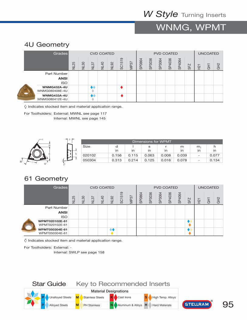
N
Material Designations
High Temp. Alloys
Hard Materials
Cast Irons
Aluminum & Alloys
Stainless Steels
PH Stainless
Unalloyed Steels
Alloyed Steels
Star Guide Key to Recommended Inserts
P M K S
HMP
W Style Turning Inserts
WNMG, WPMT
95
ºº º
NL2
5
NL3
0
NL3
7
NL4
0
NL9
2
SC
1519
MP
37
SP
0864
SP
3036
SP
3064
SP
4036
SP
4064
SFZ
H21
GH
1
GH
2
Dimensions for WPMT
Size d l s r m m1 hin in in in in in in
020102 0.156 0.115 0.063 0.008 0.039 - 0.077
050304 0.313 0.214 0.125 0.016 0.078 - 0.134
61 GeometryGrades CVD COATED PVD COATED UNCOATED
Part Number
ANSIISO
WPMT020102E-61 ◆◆WPMT020102E-61 ◆WPMT050304E-61 ◆◆ ◆◆WPMT050304E-61 ◆ ◆
Indicates stocked item and material application range.
For Toolholders: External: -
Internal: SWLP see page 158
NL2
5
NL3
0
NL3
7
NL4
0
NL9
2
SC
1519
MP
37
SP
0864
SP
3036
SP
3064
SP
4036
SP
4064
SFZ
H21
GH
1
GH
2
4U GeometryGrades CVD COATED PVD COATED UNCOATED
Part Number
ANSIISO
WNMG432A-4U ◆◆ ◆WNMG080408E-4U ◆ ◆
WNMG433A-4U ◆◆ ◆WNMG080412E-4U ◆
Indicates stocked item and material application range.
For Toolholders: External: MWNL see page 117
Internal: MWNL see page 145

96
External Toolholders ISO Designation (ISO 5608)
0˚
15˚
0˚
45˚
30˚
0˚
INCH
A
B
C
D
E
F
1 Assembly
M or CClampLock
M C L RN1 2 3 4 5
SPosicut
®
2 Insert ShapeA C D E
85° 82° 80° 55° 75°
H K L M O
120° 55° 90° 86° 135°
P R S T V
108° 360° 90° 60° 35°
W
80°
B
3 Tool Style 4 Rake
5 Hand
RRightHand
LLeft
Hand
NNeutral
K
L
N
15˚
5˚
27˚
G
J
0˚
3˚
P
Q
R
S
V
27˚30’
27° 30’
15˚
45˚
17°30’
NNegative
0Neutral
PPositive

97
External Toolholders
-6
167
48
-10
C9
6 Pocket Type
7 Tool Height
06= 0.375
08= 0.500
10= 0.625
12= 0.750
16= 1.000
20= 1.250
24= 1.500
32= 2.000
44= 0.500
55= 0.625
64= 0.750
66= 0.750
85= 1.000
86= 1.000
88= 1.000
91= 1.250
INCH
8 Insert Size
For equal sided inserts,this indicates the inscribed
circle (IC) in 1/8".
9 Qualified Method & Length
10 Shank Modification (Optional)
- Full Double Wall
S Single Wall
h
1 = 1/8
1-2 = 5/32
1-5 = 3/16
1-8 = 7/32
2 = 1/4
2-5 = 5/16
3 = 3/8
4 = 1/2
5 = 5/8
6 = 3/4
7 = 7/8
8 = 1
10 = 11/4
EXAMPLES
For rectangles and parallelograms, 2 digits arenecessary.
1st digit = Number of 1/8" in width.
2nd digit = Number of 1/4" in length.
A = 4.000
B = 4.500
C = 5.000
D= 6.000
E = 7.000
F = 8.000
G = 5.500
H = 9.000
K = 12.000
L = 14.000
Z =Length must be specified.e.g. MTANR-246Z (6.500")
INCH
BACK & END FRONT & END
M = 4.000
N = 4.500
P = 5.000
R = 6.000
S = 7.000
T = 8.000
U = 5.500
V = 9.000
X = 12.000
Y = 14.000
A = American
B = Bullard
G = Giddings & Lewis
L = LeBlond
M = Monarch
N = New Britain
S = Sheldon
IC

98
External Toolholders
l1
fInsert
b
l2
Anvil
HeadLength
Front
End
Clamp& Screw
h1
h
Stellram toolholders are available in all popularsquare shank sizes to cover the majority ofapplication areas.
There are two clamping methods for every need.
The CLAMP LOCK “M” style, for ISOnegative inserts.
A double fixation system for arduousconditions, these tools combine aneccentric pin and top clamp for extrasecurity.
M C L N R - 1 6 4
Insert Style
Insert size
ClearanceAngle
Terminology
Clamp Lock
The Stellram innovated POSICUT® “S”style, for ISO positive inserts.
A center screw held system which usessuperior quality screws to securely locatethe insert in the direction of the maincutting force.
S D J C R - 0 6 2
Insert Style
Insert size
ClearanceAngle
Terminology
Screw Lock
l1
f Insert
b
l2
Anvil
Screw
HeadLength
Front
End
h1
h

99
Application Index
MCGN 90°
PAGE 100
MCKN 75°
PAGE 101
MCLN 95°
PAGE 102
MCRN 75°
PAGE 103
MRGN
PAGE 106
MSDNN 45°
PAGE 107
MSKN 75°
PAGE 108
MSRN 75°
PAGE 109
MSSN 45°
PAGE 110
MTENN 60°
PAGE 111
MTFN 90°
PAGE 112
MTJN 93°
PAGE 113
MVJN 93°
PAGE 114
MVPN 117° 30’
PAGE 115
MVVNN 72° 30’
PAGE 116
MWLN 95°
PAGE 117
SCAC 90°
PAGE 118
SCLC 95°
PAGE 119
PAGE 120
SCLP 95° SDAC 90°
PAGE 121
SDJC 93°
PAGE 122
SDNC 62° 30’
PAGE 123
SEAP 90°
PAGE 124
SRCP
PAGE 125
SRCPN
PAGE 126
SRDC
PAGE 127
SSDC 45°
PAGE 128
STBT
PAGE 129
STGC 90°
PAGE 130
STGP 90°
PAGE 131 PAGE 132
SVJB 93°
PAGE 133
SVVC 72° 30’
PAGE 134
SVAC 90°
MDPNN 62° 30’
PAGE 105
MDJN 93°
PAGE 104

Description Dimensions (inch) Inserts Gauge Insertb l1 l2 f h h1 k z Radius
MCGNR/L-164D 1.000 6.00 1.120 1.250 1.000 1.000 5° 5° CN__43 0.031
MCGNR/L-165D 1.000 6.00 1.310 1.250 1.000 1.000 5° 5° CN__54 0.047
For Inserts refer to pages 40 - 45
Part Number Clamp Clamp Key Anvil Lock Optional Lock PinScrew Pin Anvil Screw Key
MCGN_164D CL20 XNS48 KH5103 ICSN433 NL46 S46 KH5124
MCGN_165D CL12 XNS510 KH5104 ICSN533 NL58 S58 KH5103
MCGN 90o
SPARES
Toolholders Clamp Lock System
100
MCGN 90º
For RIGHT HAND toolholders and inserts, specify R = MCGNRFor LEFT HAND toolholders and inserts, specify L = MCGNL
RH Shown

101
Toolholders Clamp Lock System
For RIGHT HAND toolholders and inserts, specify R = MCKNRFor LEFT HAND toolholders and inserts, specify L = MCKNL
Description Dimensions (inch) Inserts Gauge Insertb l1 l2 f h h1 k z Radius
MCKNR/L-124B 0.750 4.50 1.200 1.000 0.750 0.750 5° 5° CN__43 0.031
MCKNR/L-164D 1.000 6.00 1.200 1.250 1.000 1.000 5° 5° CN__43 0.031
MCKNR/L-165D 1.000 6.00 1.350 1.250 1.000 1.000 5° 5° CN__54 0.047
MCKNR/L-206E 1.250 6.00 1.470 1.500 1.250 1.250 5° 5° CN__64 0.047
MCKNR/L-246E 1.500 7.00 1.470 2.000 1.500 1.500 5° 5° CN__64 0.047
For Inserts refer to pages 40 - 45
Part Number Clamp Clamp Key Anvil Lock Optional Lock PinScrew Pin Anvil Screw Key
MCKN_124B to MCKN_164D CL20 XNS48 KH5103 ICSN433 NL46 S46 KH5124
MCKN_165D CL12 XNS510 KH5104 ICSN533 NL58 S58 KH5103
MCKN_206E to MCKN_246E CL12 XNS510 KH5104 ICSN633 NL68 S68 KH5135
MCKN 75o
MCKN 75º
SPARES
RH Shown

Toolholders Clamp Lock System
102 For RIGHT HAND toolholders and inserts, specify R = MCLNRFor LEFT HAND toolholders and inserts, specify L = MCLNL
Description Dimensions (inch) Inserts Gauge Insertb l1 l2 f h h1 k z Radius
MCLNR/L-124B 0.750 4.50 1.130 1.000 0.750 0.750 5° 5° CN__43 0.031
MCLNR/L-164C 1.000 5.00 1.130 1.250 1.000 1.000 5° 5° CN__43 0.031
MCLNR/L-164D 1.000 6.00 1.130 1.250 1.000 1.000 5° 5° CN__43 0.031
MCLNR/L-854D 1.000 6.00 1.130 1.250 1.250 1.250 5° 5° CN__43 0.031
MCLNR/L-204D 1.250 6.00 1.130 1.500 1.250 1.250 5° 5° CN__43 0.031
MCLNR/L-165D 1.000 6.00 1.310 1.250 1.000 1.000 5° 5° CN__54 0.047
MCLNR/L-205D 1.250 6.00 1.310 1.500 1.250 1.250 5° 5° CN__54 0.047
MCLNR/L-245E 1.500 7.00 1.310 2.000 1.500 1.500 5° 5° CN__54 0.047
MCLNR/L-166D 1.000 6.00 1.510 1.250 1.000 1.000 5° 5° CN__64 0.047
MCLNR/L-856D 1.000 6.00 1.510 1.250 1.250 1.250 5° 5° CN__64 0.047
MCLNR/L-206D 1.250 6.00 1.510 1.500 1.250 1.250 5° 5° CN__64 0.047
MCLNR/L-246D 1.500 6.00 1.510 2.000 1.500 1.500 5° 5° CN__64 0.047
For Inserts refer to pages 40 - 45
Part Number Clamp Clamp Key Anvil Lock Optional Lock PinScrew Pin Anvil Screw Key
MCLN_124B to MCLN_204D CL20 XNS48 KH5103 ICSN433 NL46 S46 KH5124
MCLN_165D to MCLN_245E CL12 XNS510 KH5104 ICSN533 NL58 S58 KH5103
MCLN_166D to MCLN_246D CL12 XNS510 KH5104 ICSN633 NL68 S68 KH5135
MCLN 95o
MCLN 95º
SPARES
RH Shown

103
Toolholders Clamp Lock System
For RIGHT HAND toolholders and inserts, specify R = MCRNRFor LEFT HAND toolholders and inserts, specify L = MCRNL
MCRN 75o
25
24,6
426'z
h h1
RH Shown
101,7
75º
f
ll
b
1
2
Description Dimensions (inch) Inserts Gauge Insertb l1 l2 f h h1 k z Radius
MCRNL/R-124B 0.750 4.500 1.180 0.878 0.750 0.750 6° 6° CN__43 0.031
MCRNL/R-164B 1.000 6.000 1.180 1.128 1.000 1.000 6° 6° CN__43 0.031
MCRNL/R-205B 1.250 6.000 1.350 1.351 1.250 1.250 6° 6° CN__54 0.047
MCRNL/R-206B 1.250 6.000 1.470 1.318 1.250 1.250 6° 6° CN__64 0.047
For Inserts refer to pages 40 - 45
Part Number Clamp Clamp Key Anvil Lock Optional Lock PinScrew Pin Anvil Screw Key
MCRNL/R-124B to MCRNL/R-164D CL20 XNS48 KH5103 ICSN433 NL46 S46 KH5124
MCRNL/R-205D CL12 XNS510 KH5104 ICSN533 NL58 S58 KH5103
MCRNL/R-206D CL12 XNS510 KH5104 ICSN633 NL68 S68 KH5135
MCRN 75º
SPARES

Description Dimensions (inch) Inserts Gauge Insertb l1 l2 f h h1 k z Radius
MDJNR/L-124B 0.750 4.50 1.250 1.000 0.750 0.750 5° 5° DN__43 0.031
MDJNR/L-164D 1.000 6.00 1.250 1.250 1.000 1.000 5° 5° DN__43 0.031
MDJNR/L-204D 1.250 6.00 1.250 1.500 1.250 1.250 5° 5° DN__43 0.031
For Inserts refer to pages 51 - 55
Part Number Clamp Clamp Key Anvil Lock Optional Lock PinScrew Pin Anvil Screw Key
MDJN_124B to MDJN_204D CL20 XNS48 KH5103 IDSN433 NL46 S46 KH5124
Toolholders Clamp Lock System
MDJN 93o
MDJN 93º
104
SPARES
For RIGHT HAND toolholders and inserts, specify R = MDJNRFor LEFT HAND toolholders and inserts, specify L = MDJNL
RH Shown

105
Toolholders Clamp Lock System
Description Dimensions (inch) Inserts Gauge Insertb l1 l2 f h h1 k z Radius
MDPNN-164D 1.000 6.00 1.620 0.500 1.000 1.000 - 5° DN__43 0.031
MDPNN-165D 1.000 6.00 1.880 0.500 1.000 1.000 - 8° DN__54 0.047
MDPNN-855D 1.000 6.00 1.880 0.500 1.250 1.250 - 5° DN__54 0.047
For Inserts refer to pages 51 - 55
Part Number Clamp Clamp Key Anvil Lock Optional Lock PinScrew Pin Anvil Screw Key
MDPNN-164D to 855D CL22 XNS48 KH5103 IDSN433 NL46 S46 KH5124
MDPNN 62o 30’
MDPNN 62° 30’
SPARES
Neutral Toolholder

Description Dimensions (inch) Inserts Gauge Insertb l1 l2 f h h1 k z Radius
MRGNR/L-124B 0.750 4.50 1.060 1.000 0.750 0.750 5° 5° RN__43 -
MRGNR/L-164D 1.000 6.00 1.060 1.250 1.000 1.000 5° 5° RN__43 -
For Inserts refer to page 64
Part Number Clamp Clamp Key Anvil Lock Optional Lock PinScrew Pin Anvil Screw Key
MRGN_124B to MRGN_164D CL20 XNS48 KH5124 IRSN43 NL46 S46 KH5103
Toolholders Clamp Lock System
MRGN
MRGN
106
SPARES
For RIGHT HAND toolholders and inserts, specify R = MRGNRFor LEFT HAND toolholders and inserts, specify L = MRGNL
RH Shown

107
Toolholders Clamp Lock System
Description Dimensions (inch) Inserts Gauge Insertb l1 l2 f h h1 k z Radius
MSDNN-124B 0.750 4.50 1.300 0.375 0.750 0.750 - 7° SN__43 0.031
MSDNN-164D 1.000 6.00 1.300 0.500 1.000 1.000 - 7° SN__43 0.031
MSDNN-165D 1.000 6.00 1.500 0.500 1.000 1.000 - 7° SN__54 0.047
MSDNN-855D 1.000 6.00 1.500 0.500 1.250 1.250 - 7° SN__54 0.047
MSDNN-856D 1.000 6.00 1.750 0.500 1.250 1.250 - 7° SN__64 0.047
MSDNN-206E 1.250 7.00 1.750 0.625 1.250 1.250 - 7° SN__64 0.047
For Inserts refer to pages 68 - 72
Part Number Clamp Clamp Key Anvil Lock Optional Lock PinScrew Pin Anvil Screw Key
MSDNN-124B to MSDNN-164D CL20 XNS48 KH5103 ISSN432 NL46 S46 KH5124
MSDNN-165D to MSDNN-855D CL12 XNS510 KH5104 ISSN533 NL58 S58 KH5103
MSDNN_856D to MSDNN-206E CL12 XSN510 KH5104 ISSN633 NL68 S68 KH5135
MSDNN 45o
f
45°
2
1
b
z1
h h
MSDNN 45°
SPARES
Neutral Toolholder

Description Dimensions (inch) Inserts Gauge Insertb l1 l2 f h h1 k z Radius
MSKNR/L-124B 0.750 4.50 1.220 1.000 0.750 0.750 5° 5° SN__43 0.031
MSKNR/L-164D 1.000 6.00 1.220 1.250 1.000 1.000 5° 5° SN__43 0.031
MSKNR/L-854D 1.000 6.00 1.220 1.250 1.250 1.250 5° 5° SN__43 0.031
MSKNR/L-205E 1.250 7.00 1.410 1.500 1.250 1.250 5° 5° SN__54 0.047
For Inserts refer to pages 68 - 72
Part Number Clamp Clamp Key Anvil Lock Optional Lock PinScrew Pin Anvil Screw Key
MSKN_124B to MSKN_854D CL20 XNS48 KH5103 ISSN432 NL46 S46 KH5124
MSKN_205E CL12 XNS510 KH5104 ISSN533 NL58 S58 KH5103
Toolholders Clamp Lock System
MSKN 75°
MSKN 75°
108
SPARES
For RIGHT HAND toolholders and inserts, specify R = MSKNRFor LEFT HAND toolholders and inserts, specify L = MSKNL
RH Shown

109
Toolholders Clamp Lock System
Description Dimensions (inch) Inserts Gauge Insertb l1 l2 f h h1 k z Radius
MSRNR/L-123B 0.750 4.50 1.250 0.910 0.750 0.750 5° 5° SN__32 0.031
MSRNR/L-164D 1.000 6.00 1.250 1.130 1.000 1.000 5° 5° SN__43 0.031
MSRNR/L-165D 1.000 6.00 1.500 1.103 1.000 1.000 5° 5° SN__54 0.047
MSRNR/L-206E 1.250 7.00 1.500 1.321 1.250 1.250 5° 5° SN__64 0.047
MSRNR/L-246E 1.500 7.00 1.500 1.571 1.500 1.500 5° 5° SN__64 0.047
For Inserts refer to pages 68 - 72
Part Number Clamp Clamp Key Anvil Lock Optional Lock PinScrew Pin Anvil Screw Key
MSRN_123B CL6 XNS36 KH5102 ISSN322 NL34 - KH5124
MSRN_164D CL20 XNS48 KH5103 ISSN433 NL46 S46 KH5124
MSRN_165D CL12 XNS510 KH5104 ISSN533 NL58 S58 KH5103
MSRN_206D to MSRN_246E CL12 XNS510 KH5104 ISSN633 NL68 S68 KH5135
MSRN 75o
MSRN 75°
SPARES
For RIGHT HAND toolholders and inserts, specify R = MSRNRFor LEFT HAND toolholders and inserts, specify L = MSRNL
RH Shown

Toolholders Clamp Lock System
110 For RIGHT HAND toolholders and inserts, specify R = MSSNRFor LEFT HAND toolholders and inserts, specify L = MSSNL
Description Dimensions (inch) Inserts Gauge Insertb l1 l2 f h h1 k z Radius
MSSNR/L-164D 1.000 6.00 1.230 0.925 1.000 1.000 8° 5° SN__43 0.031
MSSNR/L-165D 1.000 6.00 1.380 0.847 1.000 1.000 8° 5° SN__54 0.047
MSSNR/L-205D 1.250 6.00 1.380 1.097 1.250 1.250 6° 6° SN__54 0.047
MSSNR/L-246E 1.500 7.00 1.470 1.511 1.500 1.500 8° 5° SN__64 0.047
For Inserts refer to pages 68 - 72
Part Number Clamp Clamp Key Anvil Lock Optional Lock PinScrew Pin Anvil Screw Key
MSSN_164D CL20 XNS48 KH5103 ISSN432 NL46 S46 KH5124
MSSN_165D to MSSN_205D CL12 XNS510 KH5104 ISSN533 NL58 S58 KH5103
MSSN_246E CL12 XSN510 KH5104 ISSN633 NL68 S68 KH5135
MSSN 45o
SPARES
MSSN 45º
RH Shown
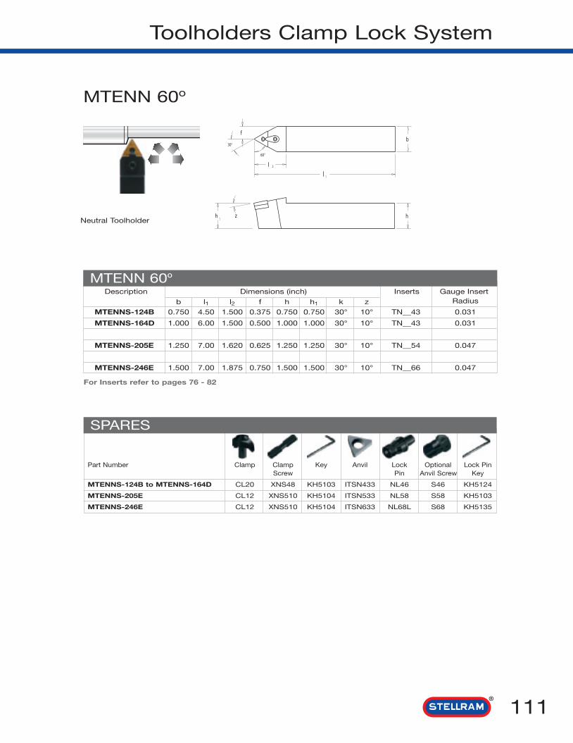
111
Toolholders Clamp Lock System
MTENN 60o
Description Dimensions (inch) Inserts Gauge Insert
b l1 l2 f h h1 k z Radius
MTENNS-124B 0.750 4.50 1.500 0.375 0.750 0.750 30° 10° TN__43 0.031
MTENNS-164D 1.000 6.00 1.500 0.500 1.000 1.000 30° 10° TN__43 0.031
MTENNS-205E 1.250 7.00 1.620 0.625 1.250 1.250 30° 10° TN__54 0.047
MTENNS-246E 1.500 7.00 1.875 0.750 1.500 1.500 30° 10° TN__66 0.047
For Inserts refer to pages 76 - 82
Part Number Clamp Clamp Key Anvil Lock Optional Lock PinScrew Pin Anvil Screw Key
MTENNS-124B to MTENNS-164D CL20 XNS48 KH5103 ITSN433 NL46 S46 KH5124
MTENNS-205E CL12 XNS510 KH5104 ITSN533 NL58 S58 KH5103
MTENNS-246E CL12 XNS510 KH5104 ITSN633 NL68L S68 KH5135
MTENN 60º
SPARES
Neutral Toolholder

Description Dimensions (inch) Inserts Gauge Insertb l1 l2 f h h1 k z Radius
MTFNR/L-163D 1.000 6.00 1.000 1.250 1.000 1.000 5° 5° *TN__33 0.031
MTFNR/L-164D 1.000 6.00 1.000 1.250 1.000 1.000 5° 5° TN__43 0.031
For Inserts refer to pages 76 - 82
Toolholders Clamp Lock System
MTFN 90o
MTFN 90º
112 For RIGHT HAND toolholders and inserts, specify R = MTFNRFor LEFT HAND toolholders and inserts, specify L = MTFNL
Part Number Clamp Clamp Key Anvil Lock Optional Lock PinScrew Pin Anvil Screw Key
MTFN_163D CL20 XNS48 KH5103 ITSN323 NL34L S34 KH5102
MTFN_164D CL20 XNS48 KH5103 ITSN432 NL46 S46 KH5124
SPARES
RH Shown
* Note: to use insert TN-32 change anvil ITSN323 to anvil ITSN333.

113
Toolholders Clamp Lock System
For RIGHT HAND toolholders and inserts, specify R = MTJNRFor LEFT HAND toolholders and inserts, specify L = MTJNL
Description Dimensions (inch) Inserts Gauge Insert
b l1 l2 f h h1 k z Radius
MTJNR/LS-123B 0.750 4.50 1.030 1.000 0.750 0.750 5° 5° *TN__33 0.031
MTJNR/LS-163D 1.000 6.00 1.030 1.250 1.000 1.000 5° 5° *TN__33 0.031
MTJNR/LS-164D 1.000 6.00 1.250 1.250 1.000 1.000 5° 5° TN__43 0.031
MTJNR/LS-204E 1.250 7.00 1.250 1.500 1.250 1.250 5° 5° TN__43 0.031
MTJNR/LS-205E 1.250 7.00 1.440 1.500 1.250 1.250 5° 5° TN__54 0.047
For Inserts refer to pages 76 - 82
-N refers to double clamping
Part Number Clamp Clamp Key Anvil Lock Optional Lock PinScrew Pin Anvil Screw Key
MTJN_123B to MTJN_163D CL20 XNS48 KH5103 ITSN323 NL34L S34 KH5102
MTJN_164D to MTJN_204E CL20 XNS48 KH5103 ITSN433 NL46 S46 KH5124
MTJN_205E CL12 XNS510 KH5104 ITSN533 NL58 S58 KH5103
MTJN 93o
MTJN 93º
SPARES
RH Shown
* Note: to use insert TN-32 change anvil ITSN323 to anvil ITSN333.

Toolholders Clamp Lock System
114 For RIGHT HAND toolholders and inserts, specify R = MVJNRFor LEFT HAND toolholders and inserts, specify L = MVJNL
Description Dimensions (inch) Inserts Gauge Insert
b l1 l2 f h h1 k z Radius
MVJNR/L-123B 0.750 4.50 1.620 1.000 0.750 0.750 3° 8° VN__33 0.031
MVJNR/L-163D 1.000 6.00 1.620 1.250 1.000 1.000 3° 8° VN__33 0.031
MVJNR/L-203D 1.250 6.00 1.620 1.500 1.250 1.250 3° 8° VN__33 0.031
MVJNR/L-164D 1.000 6.00 1.880 1.250 1.000 1.000 3° 8° VN__43 0.031
MVJNR/L-204E 1.250 7.00 1.880 1.500 1.250 1.250 3° 8° VN__43 0.031
For Inserts refer to pages 88 - 90
Part Number Clamp Clamp Key Anvil Lock Optional Lock PinScrew Pin Anvil Screw Key
MVJN_123B to MVJN_203D CL22 XNS48 KH5103 IVSN322 NL34L S34 KH5102
MVJN_164D to MVJN_204E CL30 XNS510 KH5104 IVSN432 NL46 S46 KH5124
MVJN 93o
MVJN 93º
SPARES
RH Shown

115
Toolholders Clamp Lock System
For RIGHT HAND toolholders and inserts, specify R = MVPNRFor LEFT HAND toolholders and inserts, specify L = MVPNL
Description Dimensions (inch) Inserts Gauge Insert
b l1 l2 f h h1 k z Radius
MVPNR/L-163D 1.000 6.00 1.500 1.250 1.000 1.000 9° 9° VN__33 0.031
MVPNR-203E 1.250 7.00 1.500 1.500 1.250 1.250 9° 9° VN__33 0.031
For Inserts refer to pages 88 - 90
Part Number Clamp Clamp Key Anvil Lock Optional Lock PinScrew Pin Anvil Screw Key
MVPN_163D to MVPN_203E CL22 XNS48 KH5103 IVSN322 NL34L S34 KH5102
MVPN 117o 30’
SPARES
RH Shown
MVPN 117º 30’

Toolholders Clamp Lock System
116 For RIGHT HAND toolholders and inserts, specify R = MVVNNRFor LEFT HAND toolholders and inserts, specify L = MVVNNL
Description Dimensions (inch) Inserts Gauge Insert
b l1 l2 f h h1 k z Radius
MVVNN-123A 0.750 4.00 1.620 0.375 0.750 0.750 - 14° VN__33 0.031
MVVNN-163D 1.000 6.00 1.620 0.500 1.000 1.000 - 14° VN__33 0.031
MVVNN-164D 1.000 6.00 2.060 0.500 1.000 1.000 - 14° VN__43 0.031
MVVNN-204E 1.250 7.00 2.060 0.625 1.250 1.250 - 14° VN__43 0.031
For Inserts refer to pages 85 - 87
Part Number Clamp Clamp Key Anvil Lock Optional Lock PinScrew Pin Anvil Screw Key
MVVNN-123A to MVVNN-163D CL22 XNS48` KH5103 IVSN322 NL34L S34 KH5102
MVVNN-164D to MVVNN-204E CL30 XNS510 KH5104 IVSN432 NL46 S46 KH5124
MVVNN 72o 30’
MVVNN 72º 30’
SPARES
Neutral Toolholder

117
Toolholders Clamp Lock System
Description Dimensions (inch) Inserts Gauge Insert
b l1 l2 f h h1 k z Radius
MWLNR/L-123B-N 0.750 4.50 1.070 1.000 0.750 0.750 5° 5° WN__33 0.031
MWLNR/L-163D-N 1.000 6.00 1.070 1.250 1.000 1.000 5° 5° WN__33 0.031
MWLNR/L-124B-N 0.750 4.50 1.250 1.000 0.750 0.750 5° 5° WN__43 0.031
MWLNR/L-164D-N 1.000 6.00 1.250 1.250 1.000 1.000 5° 5° WN__43 0.031
MWLNR/L-204E-N 1.250 7.00 1.250 1.500 1.250 1.250 5° 5° WN__43 0.031
MWLNR/L-244E-N 1.500 7.00 1.250 2.000 1.500 1.500 5° 5° WN__43 0.031
For Inserts refer to pages 88 - 90
Part Number Clamp Key Anvil Lock Optional Lock Pin& Screw Pin Anvil Screw Key
MWLN_123B to MWLN_163D MC2007 KH5103 MA3006 MLP1642 MLS1393 -
MWLN_124B to MWLN_244E MC2012 KH5105 MA3009 MLP1661 MLS1394 -
MWLN 95o
MWLN 95º
SPARES
RH Shown
Wedge Style Clamping
For RIGHT HAND toolholders and inserts, specify R = MWLNRFor LEFT HAND toolholders and inserts, specify L = MWLNL
101,1
95ºf b
ll
1
2

Toolholders Posicut® System
118 For RIGHT HAND toolholders and inserts, specify R = SCACRFor LEFT HAND toolholders and inserts, specify L = SCACL
Description Dimensions (inch) Inserts Gauge Insert
b l1 l2 f h h1 k z Radius
SCACR/L-062 0.375 6.000 - 0.375 0.375 0.375 - - CC_21.5 0.016
SCACR/L-083 0.500 6.000 - 0.500 0.500 0.500 - - CC__32.5 0.031
SCACR/L-103 0.625 6.000 - 0.625 0.625 0.625 - - CC__32.5 0.031
SCACR/L-123 0.750 5.000 - 0.750 0.750 0.750 - - CC__32.5 0.031
For Inserts refer to pages 38 - 39
Part Number Insert Key Anvil AnvilScrew Screw
SCAC_062 F2505T K5507 - -
SCAC_083 to SCAC_123 D4010T K5515 - -
SCAC 90o
SCAC 90º
SPARES
RH Shown

119
Toolholders Posicut® System
For RIGHT HAND toolholders and inserts, specify R = SCLCRFor LEFT HAND toolholders and inserts, specify L = SCLCL
Description Dimensions (inch) Inserts Gauge Insert
b l1 l2 f h h1 k z Radius
SCLCR/L-062 0.375 2.50 0.390 0.500 0.375 0.375 - - CC__21.5 0.016
- -
SCLCR/L-083 0.500 3.50 0.390 0.625 0.500 0.500 - - CC__32.5 0.031
SCLCR/L-124 0.750 4.50 1.000 1.000 0.750 0.750 - - CC__43 0.031
SCLCR/L-164 1.000 5.00 1.000 1.250 1.000 1.000 - - CC__43 0.031
For Inserts refer to pages 38 - 39
SCLC 95o
SCLC 95º
Part Number Insert Key Anvil AnvilScrew Screw
SCLC_062 F2507T K5507 - -
SCLC_083 D4010T K5515 - -
SCLC_124 to SCLC_164 43D4014T K5517 SA3614 SAS1760
SPARES
RH Shown

Toolholders Posicut® System
120 For RIGHT HAND toolholders and inserts, specify R = SCLPRFor LEFT HAND toolholders and inserts, specify L = SCLPL
RH Shown
Description Dimensions (inch) Inserts Gauge Insert
b l1 l2 f h h1 k z Radius
SCLPR/L-062.5 0.375 2.50 0.560 0.500 0.375 0.375 5° - CP__2.52 0.016
SCLPR/L-082.5 0.500 3.50 0.560 0.625 0.500 0.500 5° - CP__2.52 0.016
SCLPR/L-102.5 0.625 4.00 0.560 0.750 0.625 0.625 5° - CP__2.52 0.016
SCLPR/L-122.5 0.750 4.50 0.560 0.875 0.750 0.750 5° - CP__2.52 0.016
SCLP 95o
SCLP 95º
Part Number Insert Key Anvil AnvilScrew Screw
SCLP_062.5 to SCLP_122.5 SN106T K5510 - -
SPARES
For Inserts refer to pages 46 - 47

121
Toolholders Posicut® System
For RIGHT HAND toolholders and inserts, specify R = SDACRFor LEFT HAND toolholders and inserts, specify L = SDACL
Description Dimensions (inch) Inserts Gauge Insert
b l1 l2 f h h1 k z Radius
SDACR/L-062 0.375 6.000 - 0.375 0.375 0.375 - - DC__21.5 0.016
SDACR/L-083 0.500 6.000 - 0.500 0.500 0.500 - - DC__32.5 0.031
SDACR/L-103 0.625 6.000 - 0.625 0.625 0.625 - - DC__32.5 0.031
SDACR/L-123 0.750 5.000 - 0.750 0.750 0.750 - - DC__32.5 0.031
For Inserts refer to pages 48 - 50
SDAC 90o
SDAC 90º
Part Number Insert Key Anvil AnvilScrew Screw
SDAC_062 F2505T K5507 - -
SDAC_083 to SDAC_123 D4010T K5515 - -
SPARES
RH Shown

Toolholders Posicut® System
122 For RIGHT HAND toolholders and inserts, specify R = SDJCRFor LEFT HAND toolholders and inserts, specify L = SDJCL
Description Dimensions (inch) Inserts Gauge Insert
b l1 l2 f h h1 k z Radius
SDJCR/L-062 0.375 2.50 0.590 0.500 0.375 0.375 - - DC__21.5 0.016
- -
SDJCR/L-083 0.500 3.50 0.670 0.625 0.500 0.500 - - DC__32.5 0.031
SDJCR/L-103 0.625 4.00 0.670 0.750 0.625 0.625 - - DC__32.5 0.031
SDJCR/L-123 0.750 4.50 0.940 1.000 0.750 0.750 - - DC__32.5 0.031
For Inserts refer to pages 48 - 50
SDJC 93o
SDJC 93º
Part Number Insert Key Anvil AnvilScrew Screw
SDJC_062 F2507T K5507 - -
SDJC_083 to SDJC_123 D4010T K5516 SA3714 SAS1750
SPARES
RH Shown

123
Toolholders Posicut® System
Description Dimensions (inch) Inserts Gauge Insert
b l1 l2 f h h1 k z Radius
SDNCN-062 0.375 6.00 0.620 0.188 0.375 0.375 - - DC__21.5 0.016
- -
SDNCN-083 0.500 6.00 0.620 0.250 0.500 0.500 DC__32.5 0.031
SDNCN-103 0.625 6.00 0.620 0.313 0.625 0.625 - - DC__32.5 0.031
SDNCN-123 0.750 5.00 0.620 0.375 0.750 0.750 - - DC__32.5 0.031
For Inserts refer to pages 48 - 50
SDNC 62o 30’
SDNC 62º 30’
Part Number Insert Key Anvil AnvilScrew Screw
SDNCN-062 F2507T K5507 - -
SDNCN-083 to SDNCN-123 D4010T K5515 - -
SPARES
Neutral Toolholder

Toolholders Posicut® System
124
Description Dimensions (inch) Inserts Gauge Insert
b l1 l2 f h h1 k z Radius
SEAPR/L-062.5 0.375 6.00 0.620 0.375 0.375 0.375 - - EP__08M3 0.016
SEAPR/L-082.5 0.500 6.00 0.620 0.500 0.500 0.500 - - EP__08M3 0.016
SEAPR/L-102.5 0.625 6.00 0.620 0.625 0.625 0.625 - - EP__08M3 0.016
SEAPR/L-122.5 0.750 5.00 0.620 0.750 0.750 0.750 - - EP__08M3 0.016
For Inserts refer to pages 57 - 61
SEAP 90o
SEAP 90º
Part Number Insert Key Anvil AnvilScrew Screw
SEAP_062.5 to SEAP_122.5 A3006T K5509 - -
SPARES
For RIGHT HAND toolholders and inserts, specify R = SEAPRFor LEFT HAND toolholders and inserts, specify L = SEAPL
RH Shown

125
Toolholders Posicut® System
Description Dimensions (inch) Inserts Gauge Insert
b l1 l2 f h h1 k z Radius
SRCPR/L-164 1.000 6.00 1.500 0.750 1.000 1.000 - - RD8-2C -
SRCPR/L-204 1.250 7.00 1.500 1.000 1.250 1.250 - - RD8-2C -
SRCPR/L-244 1.500 7.00 1.500 1.250 1.500 1.500 - - RD8-2C -
SRCP
SRCP
Part Number Insert Key Anvil AnvilScrew Screw
SRCP_164 to SRCP_244 SN111 KH5124
SPARES
For RIGHT HAND toolholders and inserts, specify R = SRCPRFor LEFT HAND toolholders and inserts, specify L = SRCPL
For Inserts refer to page 63
RH Shown

Toolholders Posicut® System
126
Description Dimensions (inch) Inserts Gauge Insert
b l1 l2 f h h1 k z Radius
SRCPN-164 1.000 6.00 1.500 0.500 1.000 1.000 - - RD8-2C -
SRCPN-854 1.000 6.00 1.500 0.500 1.250 1.250 - - RD8-2C -
SRCPN-204 1.250 7.00 1.500 0.625 1.250 1.250 - - RD8-2C -
SRCPN-244 1.500 7.00 1.500 0.750 1.500 1.500 - - RD8-2C -
SRCPN
SRCPN
Part Number Insert Key Anvil AnvilScrew Screw
SRCPN-164 to SRCPN-244 SN111 KH5124 - -
SPARES
For Inserts refer to page 63
Neutral Toolholder

127
Toolholders Posicut® System
Description Dimensions (inch) Inserts Gauge Insert
b l1 l2 f h h1 k z Radius
SRDCN-103 0.625 4.00 0.810 0.313 0.625 0.625 - - RC__32.5 -
SRDCN-1210 0.750 5.00 0.810 0.375 0.750 0.750 - -RC__32.5 /
-RC__10T3
For Inserts refer to pages 62 - 63
SRDC
SRDC
Part Number Insert Key Anvil AnvilScrew Screw
SRDCN-103 to SRDCN-1210 SN118T K5507 - -
SPARES
Neutral Toolholder

Description Dimensions (inch) Inserts Gauge Insert
b l1 l2 f h h1 k z Radius
SSDCN-083 0.500 3.50 0.630 0.250 0.500 0.500 - - SC__32.5 0.031
SSDCN-103 0.625 4.00 0.630 0.312 0.625 0.625 - - SC__32.5 0.031
SSDCN-124 0.750 4.50 0.810 0.375 0.750 0.750 - - SC__43 0.031
SSDCN-164 1.000 6.00 0.810 0.500 1.000 1.000 - - SC__43 0.031
For Inserts refer to pages 66 - 67
Toolholders Posicut® System
SSDC 45o
SSDC 45º
128
Part Number Insert Key Anvil AnvilScrew Screw
SSDCN-083 to SSDCN-103 D4010T K5515
SSDCN-124 to SSDCN-164 SN119T K5517 SA3514 SAS1760
SPARES
Neutral Toolholder

129
Toolholders Posicut® System
Description Dimensions (inch) Inserts Gauge Insert
b l1 l2 f h h1 k z Radius
STBTR-062.5 0.375 5.91 - 0.375 0.375 0.375 - - SBET0903 0.016
STBTR-082.5 0.500 5.91 - 0.500 0.500 0.500 - - SBET0903 0.016
STBTR-102.5 0.625 5.91 - 0.625 0.625 0.625 - - SBET0903 0.016
STBTR-122.5 0.750 4.92 - 0.750 0.750 0.750 - - SBET0903 0.016
For Inserts refer to page 65
STBT
STBT
Part Number Insert Key Anvil AnvilScrew Screw
STBTR-062.5 to STBTR-122.5 F3008T K5509 - -
SPARES
NOTE: The part number for these tools are Stellram specific as ISO 5608 does not cater for this typeof tool. Available in RIGHT HAND only.
RH Shown

Description Dimensions (inch) Inserts Gauge Insert
b l1 l2 f h h1 k z Radius
STGCR/L-062 0.375 2.50 0.500 0.500 0.375 0.375 - - TC__21.5 0.016
STGCR/L-082 0.500 3.50 0.560 0.625 0.500 0.500 - - TC__21.5 0.016
For Inserts refer to pages 74 - 75
STGC 90o
STGC 90º
Toolholders Posicut® System
130
Part Number Insert Key Anvil AnvilScrew Screw
STGC_062 to STGC_082 F2507T K5507 - -
SPARES
For RIGHT HAND toolholders and inserts, specify R = STGCRFor LEFT HAND toolholders and inserts, specify L = STGCL
RH Shown

131
Toolholders Posicut® System
For RIGHT HAND toolholders and inserts, specify R = STGPRFor LEFT HAND toolholders and inserts, specify L = STGPL
Description Dimensions (inch) Inserts Gauge Insert
b l1 l2 f h h1 k z Radius
STGPR/L-062 0.375 2.50 0.560 0.500 0.375 0.375 5° - TP__22 0.016
STGPR/L-082 0.500 3.50 0.560 0.625 0.500 0.500 5° - TP__22 0.016
STGPR/L-103 0.625 4.00 0.750 0.750 0.625 0.625 5° - TP__32 0.031
STGPR/L-123 0.750 4.50 0.750 1.000 0.750 0.750 5° - TP__32 0.031
STGP 90o
STGP 90º
Part Number Insert Key Anvil AnvilScrew Screw
STGP_062 to STGP_082 SN106T K5510 - -
STGP_103 to STGP_123 SN101T K5520 - -
SPARES
RH Shown
For Inserts refer to pages 83 - 84

Description Dimensions (inch) Inserts Gauge Insert
b l1 l2 f h h1 k z Radius
SVACR/L-062.5 0.375 6.00 0.620 0.375 0.375 0.375 - - VC__1303 0.016
SVACR/L-082.5 0.500 6.00 0.620 0.500 0.500 0.500 - - VC__1303 0.016
SVACR/L-102.5 0.625 6.00 0.620 0.625 0.625 0.625 - - VC__1303 0.016
SVACR/L-122.5 0.750 5.00 0.620 0.750 0.750 0.750 - - VC__1303 0.016
For Inserts refer to pages 86 - 87
Toolholders Posicut® System
SVAC 90o
90°
2
0°
1
h1
b
h
f
SVAC 90º
132
Part Number Insert Key Anvil AnvilScrew Screw
SVAC_062.5 to SVAC_122.5 F3008T K5509 - -
SPARES
For RIGHT HAND toolholders and inserts, specify R = SVACRFor LEFT HAND toolholders and inserts, specify L = SVACL
RH Shown

133
Toolholders Posicut® System
Description Dimensions (inch) Inserts Gauge Insert
b l1 l2 f h h1 k z Radius
SVJBR/L-083 0.500 3.50 1.000 0.625 0.500 0.500 - - VB__33 0.031
SVJBR/L-123 0.750 4.50 1.000 1.000 0.750 0.750 - - VB__33 0.031
SVJBR/L-163 1.000 6.00 1.500 1.250 1.000 1.000 - - VB__33 0.031
For Inserts refer to page 85
SVJB 93o
SVJB 93°
Part Number Insert Key Anvil AnvilScrew Screw
SVJB_083 SN118T K5515 - -
SVJB_123 to SVJB_163 F3512T K5515 SA 3718 SAS 1750
SPARES
For RIGHT HAND toolholders and inserts, specify R = SVJBRFor LEFT HAND toolholders and inserts, specify L = SVJBL
RH Shown
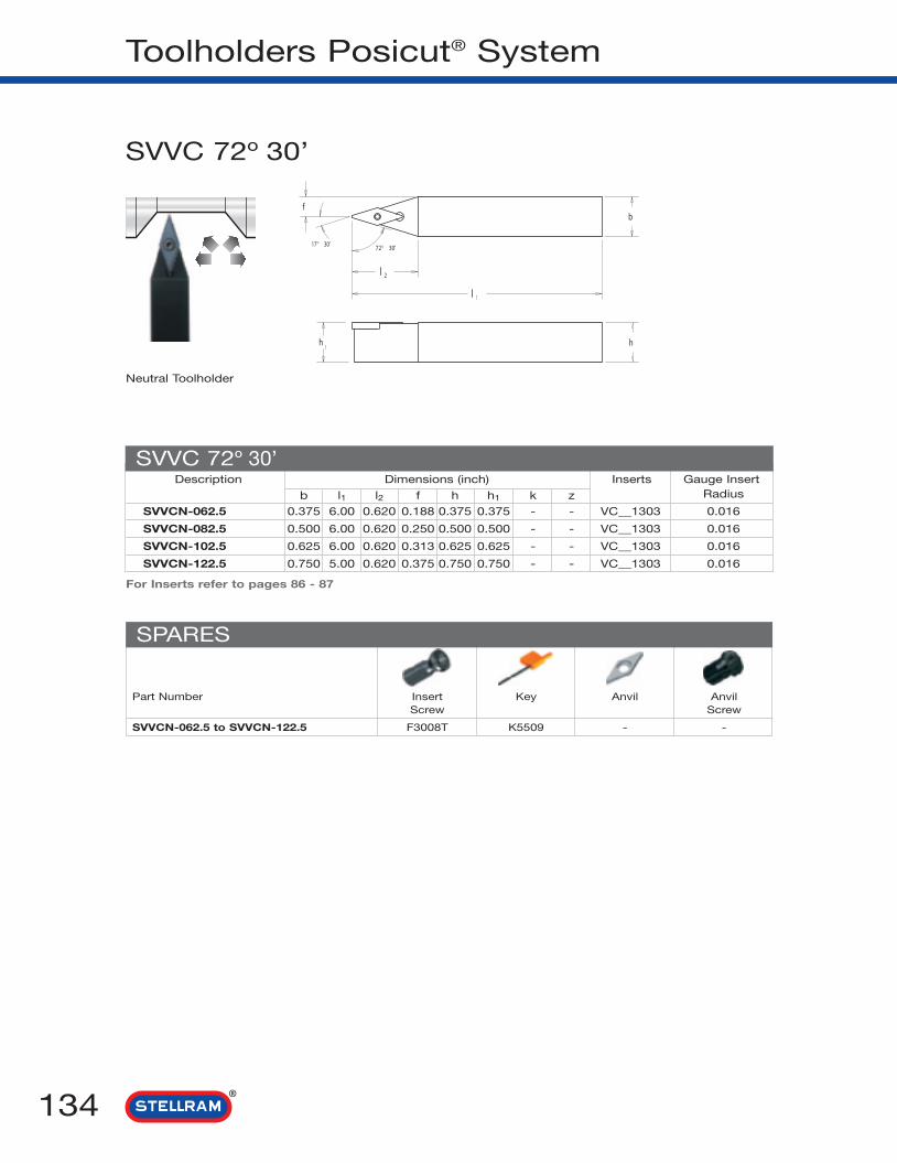
Toolholders Posicut® System
134
Description Dimensions (inch) Inserts Gauge Insert
b l1 l2 f h h1 k z Radius
SVVCN-062.5 0.375 6.00 0.620 0.188 0.375 0.375 - - VC__1303 0.016
SVVCN-082.5 0.500 6.00 0.620 0.250 0.500 0.500 - - VC__1303 0.016
SVVCN-102.5 0.625 6.00 0.620 0.313 0.625 0.625 - - VC__1303 0.016
SVVCN-122.5 0.750 5.00 0.620 0.375 0.750 0.750 - - VC__1303 0.016
For Inserts refer to pages 86 - 87
SVVC 72o 30’
SVVC 72º 30’
Part Number Insert Key Anvil AnvilScrew Screw
SVVCN-062.5 to SVVCN-122.5 F3008T K5509 - -
SPARES
Neutral Toolholder

135
Internal Boring Bars
Stellram boring bars are available in all populardiameters to cover the majority of application areas.
There are two clamping methods for every need.
The Stellram innovated Posicut® “S” style,for ISO positive inserts.
A center screw-held system which usessuperior quality screws to securely locatethe insert in the direction of the maincutting force.
A S S K C R 1 0 3
Insert Style
Insert size
ClearanceAngle
Terminology
1 Screw Lock Posicut®
The CLAMP LOCK “M” style, for ISOnegative inserts.
A double fixation for arduous conditions,these boring bars combine an eccentric pinand top clamp for extra security.
Terminology
2 Clamp Lock
S I M C K N R - 2 0 4
Insert Style
Insert size
ClearanceAngle
l1
f Insert
d
l2
Anvil
Screw
HeadLength
Coolant Hole
h1
Front
End
ThroughCoolant
l1
f Insert
d
l2 AnvilHeadLength
Clamp& Screw
h1
Front
End

2 Assembly
136
Internal Boring Bar Clamp Lock Designation
1 Bar Type
SI M C NL1 2 3 4 5
4 Bar Style
M or CClampLock
SPosicut
®
Steel shank and
coolant hole.
Steel shank and anti-
vibration device.
Cemented carbide
shank with steel
head.
carbide integral
shank
Steel shank,
anti-vibration device
and coolant hole.
Cemented carbide
shank with steel
head and coolant
hole.
A
B
C
CI
D
E
Cemented carbide
shank with
steel head and
anti-vibration device.
Cemented carbide
shank with steel
head, coolant hole
and anti-vibration
device.
Heavy metal shank.
Heavy metal shank
and coolant hole.
Steel shank.
Steel intregal shank.
F
G
H
J
SSI
3 Insert ShapeA C D E
85° 82° 80° 55° 75°
H K L M O
120° 55° 90° 86° 135°
P R S T V
108° 360° 90° 60° 35°
W
80°
B
INCH INCH
0˚
15˚
5˚
17˚30’
45˚
F
K
l
q
s
3˚
27˚70’
10°
5˚
5°
u
w
X
y
Z
5 Rake
NNegative
0Neutral
PPositive

137
R6
-7
208
F10
49
11 Optional
A Adjustable.
W Internal coolant provision.
8 Bar ø
d
10 Bar LengthINCH
F = 3.150
H = 3.937
K = 4.921
M = 5.905
P = 6.693
Q = 7.087
R = 7.874
S = 9.842
T = 11.811
U = 13.780
V = 15.748
W = 17.716
Y = 19.685
X = SPECIAL
04 = 0.250
05 = 0.312
06 = 0.375
08 = 0.500
10 = 0.625
12 = 0.750
16 = 1.000
20 = 1.250
24 = 1.500
28 = 1.750
32 = 2.000
36 = 2.250
40 = 2.500
INCH
-11
l1
6 Hand
RRightHand
LLeft
Hand
NNeutral
7 Pocket Type
- Full Double Wall
S Single Wall
9 Insert Size
For equal sided inserts,this indicates the inscribed
circle (IC) in 1/8".
1 = 1/8
1-2 = 5/32
1-5 = 3/16
1-8 = 7/32
2 = 1/4
2-5 = 5/16
3 = 3/8
4 = 1/2
5 = 5/8
6 = 3/4
7 = 7/8
8 = 1
10 = 11/4
EXAMPLES
For rectangles and parallelograms, 2 digits arenecessary.
1st digit = Number of 1/8" in width.
2nd digit = Number of 1/4" in length.
IC

138
Application Index
MCKN 75°
PAGE 139
MCLN 95°
PAGE 140
MDQN 107° 30’
PAGE 141
MDUN 93°
PAGE 142
MSKN 75°
PAGE 143
MVUN 93°
PAGE 144
MWLN
PAGE 145
SCLC 95°
PAGE 146
SCLP 95°
PAGE 147
SDUC 93°
PAGE 148
SDWC 62° 30’
PAGE 149
SDXC 100°
PAGE 150
SDZC 95°
PAGE 151
SELP 95°
PAGE 152
SSKC 75°
PAGE 153
STUC 93°
PAGE 154
STUP 93°
PAGE 155
SVQC 107° 30’
PAGE 156
SVUC 93°
PAGE 157
SWLP 95°
PAGE 158

139
Boring Bars Clamp Lock System
Description Dimensions (inch) Inserts Gauge InsertMin. Bore ø d l1 f h1 k z Radius
SIMCKNR-204 1.500 1.250 14.00 0.765 0.625 14° 5° CN__43 0.031
SIMCKNR-244 1.750 1.500 14.00 0.890 0.750 12° 5° CN__43 0.031
SIMCKNR-324 2.500 2.000 16.00 1.250 1.000 12° 5° CN__43 0.031
SIMCKNR-245 1.750 1.500 14.00 0.890 0.750 14° 5° CN__54 0.047
SIMCKNR/L-326* 2.500 2.000 16.00 1.250 1.000 12° 5° CN__64 0.047
For Inserts refer to pages 36 - 41
MCKN 75°
Part Number Clamp Clamp Key Anvil Lock Optional Lock PinScrew Pin Anvil Screw Key
SIMCKN_204 to SI-MCKNR-324 CL20 XNS48 KH5103 ICSN432 NL46 S46 KH5124
SIMCKN_245 CL12 XNS510 KH5104 ICSN533 NL58 S58 KH5103
SIMCKN_326 CL12 XNS510 KH5104 ICSN633 NL68 S68 KH5135
MCKN 75°
Min. BoreDia.
SPARES
RH Shown
* Note: Non - stocked item
For RIGHT HAND toolholders and inserts, specify R = SI-MCKNRFor LEFT HAND toolholders and inserts, specify L = SI-MCKNL
Through coolant standard

MCLN 95°
Description Dimensions (inch) Inserts Gauge InsertMin. Bore ø d l1 f h1 k z Radius
SIMCLNR/L-164 1.014 1.000 12.00 0.640 0.500 14° 5° CN__43 0.031
SIMCLNR/L-204 1.500 1.250 14.00 0.765 0.625 14° 5° CN__43 0.031
SIMCLNR/L-244 1.750 1.500 14.00 0.890 0.750 12° 5° CN__43 0.031
SIMCLNR/L-284 2.000 1.750 14.00 1.015 0.875 12° 5° CN__43 0.031
SIMCLNR-245 1.780 1.500 14.00 0.890 0.750 14° 5° CN__54 0.047
SIMCLNR/L-285 2.056 1.750 14.00 1.015 0.875 12° 5° CN__54 0.047
SIMCLNR/L-325 2.056 2.000 16.00 1.281 1.000 12° 5° CN__54 0.047
SIMCLNR/L-326 2.056 2.000 16.00 1.281 1.000 12° 5° CN__64 0.047
For Inserts refer to pages 40 - 45
MCLN 95°
Boring Bars Clamp Lock System
140
Min. BoreDia.
For RIGHT HAND toolholders and inserts, specify R = SIMCLNRFor LEFT HAND toolholders and inserts, specify L = SIMCLNL
Part Number Clamp Clamp Key Anvil Lock Optional Lock PinScrew Pin Anvil Screw Key
SIMCLN_164 CL20 XNS47 KH5103 - NL44 - KH5124
SIMCLN_204 to SIMCLN_284 CL20 XNS48 KH5103 ICSN432 NL46 S46 KH5124
SIMCLN_245 to SIMCLN_325 CL12 XNS510 KH5104 ICSN533 NL58 S58 KH5103
SIMCLN_326 CL12 XNS510 KH5104 ICSN633 NL68 S68 KH5135
SPARES
RH Shown
Through coolant standard

141
Boring Bars Clamp Lock System
For RIGHT HAND toolholders and inserts, specify R = SI-MDQNRFor LEFT HAND toolholders and inserts, specify L = SI-MDQNL
Description Dimensions (inch) Inserts Gauge InsertMin. Bore ø d l1 f h1 k z Radius
SIMDQNR/L-244 2.025 1.500 14.00 1.125 0.750 10° 5° DN__43 0.031
For Inserts refer to pages 51 - 55
MDQN 107° 30’
Part Number Clamp Clamp Key Anvil Lock Optional Lock PinScrew Pin Anvil Screw Key
SIMDQN_244 CL20 XNS48 KH5103 IDSN432 NL46 S46 KH5124
MDQN 107° 30’
Min. BoreDia.
SPARES
RH Shown
Through coolant standard

MDUN 93°
93
3
1
d
f
5
Description Dimensions (inch) Inserts Gauge InsertMin. Bore ø d l1 f h1 k z Radius
SIMDUNR/L-204 2.000 1.250 14.00 1.000 0.625 10° 5° DN__43 0.031
SIMDUNR/L-244 2.250 1.500 14.00 1.125 0.750 10° 5° DN__43 0.031
For Inserts refer to pages 51 - 55
MDUN 93°
Boring Bars Clamp Lock System
142
k
h1
Min. BoreDia.
For RIGHT HAND toolholders and inserts, specify R = SI-MDUNRFor LEFT HAND toolholders and inserts, specify L = SI-MDUNL
Part Number Clamp Clamp Key Anvil Lock Optional Lock PinScrew Pin Anvil Screw Key
SIMDUN_204 to SIMDUN_244 CL20 XNS48 KH5103 IDSN432 NL46 S46 KH5124
SPARES
RH Shown
Through coolant standard

143
Boring Bars Clamp Lock System
For RIGHT HAND toolholders and inserts, specify R = SI-MSKNRFor LEFT HAND toolholders and inserts, specify L = SI-MSKNL
Description Dimensions (inch) Inserts Gauge InsertMin. Bore ø d l1 f h1 k z Radius
SIMSKNR/L-204 1.053 1.250 14.00 0.765 0.625 13° 5° SN__43 0.031
SIMSKNR/L-244 1.780 1.500 14.00 0.890 0.750 10° 5° SN__43 0.031
SIMSKNR/L-325 2.056 2.000 16.00 1.281 1.000 12° 5° SN__54 0.047
SIMSKNR-326* 2.056 2.000 16.00 1.281 1.000 12° 5° SN__64 0.047
For Inserts refer to pages 68 - 72
MSKN 75°
Part Number Clamp Clamp Key Anvil Lock Optional Lock PinScrew Pin Anvil Screw Key
SIMSKN_204 to SIMSKN_244 CL20 XNS48 KH5103 ISSN432 NL46 S46 KH5124
SIMSKN_325 CL12 XNS510 KH5104 ISSN533 NL58 S58 KH5103
SIMSKNR326 CL12 XNS510 KH5104 ISSN633 NL68 S68 KH5104
MSKN 75°
Min. BoreDia.
SPARES
RH Shown
* Note: Non - stocked item
Through coolant standard

Description Dimensions (inch) Inserts Gauge InsertMin. Bore ø d l1 f h1 k z Radius
SIMVUNR/L-203 2.250 1.250 14.00 1.125 0.625 10° 5° VN__33 0.031
SIMVUNR-243 2.500 1.500 14.00 1.250 0.750 10° 5° VN__33 0.031
For Inserts refer to pages 88 - 90
MVUN 93°
Part Number Clamp Clamp Key Anvil Lock Optional Lock PinScrew Pin Anvil Screw Key
SIMVUN_203 to SIMVUNR-243 CL20 XNS48 KH5103 IVSN322 NL34L S34 KH5102
Boring Bars Clamp Lock System
MVUN 93°
144
Min. BoreDia.
For RIGHT HAND toolholders and inserts, specify R = SI-MVUNRFor LEFT HAND toolholders and inserts, specify L = SI-MVUNL
SPARES
RH Shown
Through coolant standard
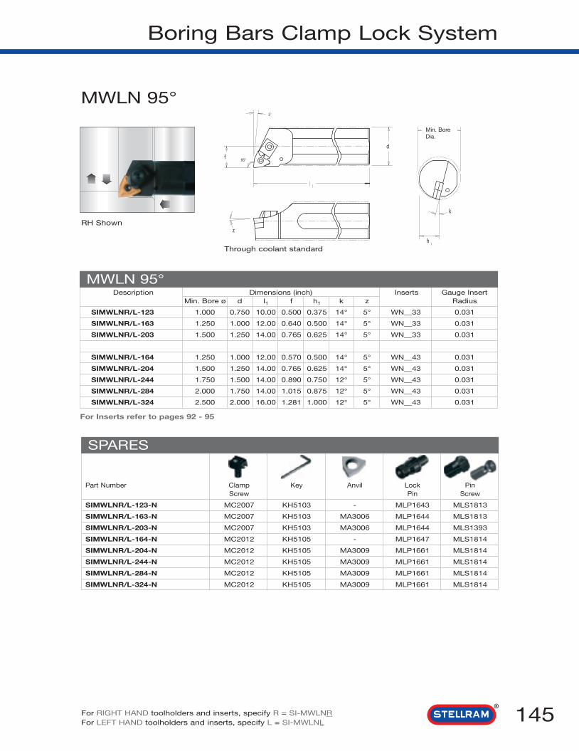
145
Boring Bars Clamp Lock System
MWLN 95°
Description Dimensions (inch) Inserts Gauge InsertMin. Bore ø d l1 f h1 k z Radius
SIMWLNR/L-123 1.000 0.750 10.00 0.500 0.375 14° 5° WN__33 0.031
SIMWLNR/L-163 1.250 1.000 12.00 0.640 0.500 14° 5° WN__33 0.031
SIMWLNR/L-203 1.500 1.250 14.00 0.765 0.625 14° 5° WN__33 0.031
SIMWLNR/L-164 1.250 1.000 12.00 0.570 0.500 14° 5° WN__43 0.031
SIMWLNR/L-204 1.500 1.250 14.00 0.765 0.625 14° 5° WN__43 0.031
SIMWLNR/L-244 1.750 1.500 14.00 0.890 0.750 12° 5° WN__43 0.031
SIMWLNR/L-284 2.000 1.750 14.00 1.015 0.875 12° 5° WN__43 0.031
SIMWLNR/L-324 2.500 2.000 16.00 1.281 1.000 12° 5° WN__43 0.031
For Inserts refer to pages 92 - 95
MWLN 95°
Min. BoreDia.
For RIGHT HAND toolholders and inserts, specify R = SI-MWLNRFor LEFT HAND toolholders and inserts, specify L = SI-MWLNL
SPARES
RH Shown
Part Number Clamp Key Anvil Lock PinScrew Pin Screw
SIMWLNR/L-123-N MC2007 KH5103 - MLP1643 MLS1813
SIMWLNR/L-163-N MC2007 KH5103 MA3006 MLP1644 MLS1813
SIMWLNR/L-203-N MC2007 KH5103 MA3006 MLP1644 MLS1393
SIMWLNR/L-164-N MC2012 KH5105 - MLP1647 MLS1814
SIMWLNR/L-204-N MC2012 KH5105 MA3009 MLP1661 MLS1814
SIMWLNR/L-244-N MC2012 KH5105 MA3009 MLP1661 MLS1814
SIMWLNR/L-284-N MC2012 KH5105 MA3009 MLP1661 MLS1814
SIMWLNR/L-324-N MC2012 KH5105 MA3009 MLP1661 MLS1814
Through coolant standard

SCLC 95o
Description Dimensions (inch) Inserts Gauge InsertMin. Bore ø d l1 f h1 k z Radius
ASCLCR/L-062 0.500 0.375 6.00 0.250 0.188 9° 3° CC__21.5 0.016
ASCLCR/L-082 0.625 0.500 6.00 0.313 0.250 7° 3° CC__21.5 0.016
ASCLCR/L-103 0.720 0.625 8.00 0.406 0.313 8° 5° CC__32.5 0.031
ASCLCR/L-123 1.000 0.750 10.00 0.500 0.375 7° 5° CC__32.5 0.031
For Inserts refer to pages 38 - 39
SCLC 95°
Part Number Insert Key Anvil AnvilScrew Screw
ASCLC_062 to CISCLC_062 SN127T K5509 - -
ASCLC_082 to CISCLC_082 SN116T K5507 - -
ASCLC_103 to CISCLC_103 SN123T K5515 - -
ASCLC_123 to CISCLC_123 SN118T K5515 - -
Boring Bars Posicut® System
146
Min. BoreDia.
Description Dimensions (inch) Inserts Gauge InsertMin. Bore ø d l1 f h1 k z Radius
CISCLCR/L-062 0.500 0.375 6.00 0.250 0.188 9° 3° CC__21.5 0.016
CISCLCR/L-082 0.625 0.500 6.00 0.313 0.250 7° 3° CC__21.5 0.016
CISCLCR/L-123 1.000 0.750 10.00 0.500 0.375 7° 3° CC__32.5 0.031
Anti-Vibration Bars (no through coolant)
SPARES
For RIGHT HAND toolholders and inserts, specify R = ASCLCRFor LEFT HAND toolholders and inserts, specify L = ASCLCL
RH Shown
Through coolant standard

147
Boring Bars Posicut® System
For Inserts refer to pages 46 - 47
For RIGHT HAND toolholders and inserts, specify R = SISCLPRFor LEFT HAND toolholders and inserts, specify L = SISCLPL
SCLP 95o
Description Dimensions (inch) Inserts Gauge InsertMin. Bore ø d l1 f h1 k z Radius
SISCLPR/L-62.5 0.500 0.375 6.00 0.250 0.188 7° 5° CP__2.52 0.016
SISCLPR/L-82.5 0.625 0.500 8.00 0.312 0.250 6° 5° CP__2.52 0.016
SISCLPR/L-102.5 0.810 0.625 10.00 0.406 0.313 4° 5° CP__2.52 0.016
SISCLPR/L-122.5 1.000 0.750 10.00 0.500 0.375 3° 5° CP__2.52 0.016
SCLP 95°
Part Number Insert Key Anvil AnvilScrew Screw
SISCLP_62.5 to SISCLP_122.5 SN106T K5510 - -
Min. BoreDia.
Description Dimensions (inch) Inserts Gauge InsertMin. Bore ø d l1 f h1 k z Radius
CISCLPR-62.5 0.500 0.375 6.00 0.250 0.188 7° 5° CP__2.52 0.016
CISCLPR-82.5 0.620 0.500 8.00 0.312 0.250 6° 5° CP__2.52 0.016
CISCLPR-102.5 0.810 0.625 10.00 0.406 0.313 4° 5° CP__2.52 0.016
CISCLPR-122.5 1.000 0.750 10.00 0.500 0.375 3° 5° CP__2.52 0.016
Anti-Vibration Bars (no through coolant)
SPARES
RH Shown
Through coolant standard

Boring Bars Posicut® System
148
SDUC 93o
Description Dimensions (inch) Inserts Gauge InsertMin. Bore ø d l1 f h1 k z Radius
ASDUCR/L-082 0.780 0.500 6.00 0.500 0.250 6° 3° DC__21.5 0.016
ASDUCR/L-102 0.780 0.625 10.00 0.438 0.313 - 3° DC__21.5 0.016
ASDUCR/L-123 1.030 0.750 10.00 0.625 0.375 5° 5° DC__32.5 0.031
ASDUCR/L-163 1.280 1.000 12.00 0.750 0.500 - 5° DC__32.5 0.031
For Inserts refer to pages 48 - 50
SDUC 93°
Part Number Insert Key Anvil AnvilScrew Screw
ASDUC_082 SN116T K5507 - -
ASDUC_102 F2505T K5507 - -
ASDUC_123 to ASDUC_163 D4008T K5515 - -
SPARES
Min. BoreDia.
For RIGHT HAND toolholders and inserts, specify R = ASDUCRFor LEFT HAND toolholders and inserts, specify L = ASDUCL
RH Shown
Through coolant standard

149
Boring Bars Posicut® System
SDWC 62° 30’
Description Dimensions (inch) Inserts Gauge InsertMin. Bore ø d l1 f h1 k z Radius
SSDWCR/L-082 0.780 0.500 6.00 0.500 0.250 5° - DC__21.5 0.016
SSDWCR/L-102 0.910 0.625 8.00 0.563 0.313 5° - DC__21.5 0.016
SSDWCR/L-123 1.160 0.750 10.00 0.750 0.375 5° - DC__32.5 0.031
SSDWCR/L-163 1.380 1.000 12.00 0.844 0.500 5° - DC__32.5 0.031
For Inserts refer to pages 48 - 50
SDWC 62° 30’
Part Number Insert Key Anvil AnvilScrew Screw
SSDWC_082 to SSDWC_102 F2505T K5507 - -
SSDWC_123 to SSDWC_163 D4008T K5515 - -
SPARES
Min. BoreDia.
For RIGHT HAND toolholders and inserts, specify R = SSDWCRFor LEFT HAND toolholders and inserts, specify L = SSDWCL
RH Shown
Through coolant standard

Boring Bars Posicut® System
SDXC 100o
150
Description Dimensions (inch) Inserts Gauge InsertMin. Bore ø d l1 f h1 k z Radius
ASDXCR/L-082 0.660 0.500 6.00 0.375 0.250 5° 3° DC__21.5 0.016
ASDXCR/L-102 0.780 0.625 8.00 0.438 0.313 5° 3° DC__21.5 0.016
ASDXCR/L-123 0.910 0.750 10.00 0.500 0.375 5° 5° DC__32.5 0.031
ASDXCR/L-163 1.220 1.000 12.00 0.688 0.500 5° 5° DC__32.5 0.031
For Inserts refer to pages 48 - 50
SDXC 100°
Part Number Insert Key Anvil AnvilScrew Screw
ASDXC_082 to ASDXC_102 F2505T K5507 - -
ASDXC_123 to ASDXC_163 D4008T K5515 - -
SPARES
Min. BoreDia.
For RIGHT HAND toolholders and inserts, specify R = ASDXCRFor LEFT HAND toolholders and inserts, specify L = ASDXCL
RH Shown
Through coolant standard

151
Boring Bars Posicut® System
SDZC 95o
For Inserts refer to pages 48 - 50
SDZC 95°
Part Number Insert Key Anvil AnvilScrew Screw
ASDZC_082 to ASDZC_102 F2505T K5507 - -
ASDZC_123 to ASDZC_163 D4008T K5515 - -
SPARES
Min. BoreDia.
Description Dimensions (inch) Inserts Gauge InsertMin. Bore ø d l1 l2 f h1 k z Radius
ASDZCR/L-082 0.780 0.500 6.51 6.000 0.500 0.250 5° - DC__21.5 0.016
ASDZCR/L-102 0.910 0.625 8.51 8.000 0.563 0.313 5° - DC__21.5 0.016
ASDZCR/L-123 1.160 0.750 10.71 10.000 0.750 0.375 5° - DC__32.5 0.031
ASDZCR/L-163 1.470 1.000 12.89 12.000 0.938 0.500 5° - DC__32.5 0.031
For RIGHT HAND toolholders and inserts, specify R = SSDZCRFor LEFT HAND toolholders and inserts, specify L = SSDZCL
RH Shown
Through coolant standard

Boring Bars Posicut® System
152 For RIGHT HAND toolholders and inserts, specify R = ASELPRFor LEFT HAND toolholders and inserts, specify L = ASELPL
SELP 95o
Description Dimensions (inch) Inserts Gauge InsertMin. Bore ø d l1 f h1 k z Radius
ASELPR/L-051.5 0.440 0.313 4.00 0.250 0.156 0° 0° EP__0402 0.016
ASELPR/L-062 0.500 0.375 5.00 0.281 0.188 5° 3° EP__0602 0.016
ASELPR/L-082 0.630 0.500 6.00 0.344 0.250 5° 3° EP__0602 0.016
ASELPR/L-082.5 0.630 0.500 6.00 0.344 0.250 5° 3° EP__08M3 0.016
ASELPR/L-102.5 0.780 0.625 8.00 0.438 0.313 5° 3° EP__08M3 0.016
ASELPR/L-122.5 0.910 0.750 10.00 0.500 0.375 5° 5° EP__08M3 0.016
For Inserts refer to pages 57 - 61
SELP 95°
Part Number Insert Key Anvil AnvilScrew Screw
ASELP_051.5 F2004T K5506 - -
ASELP_062 F2505T K5507 - -
ASELP_082/82.5 to ASELP_122.5 A3006T K5509 - -
SPARES
Min. BoreDia.
RH Shown
Through coolant standard

153
Boring Bars Posicut® System
For RIGHT HAND toolholders and inserts, specify R = ASSKCRFor LEFT HAND toolholders and inserts, specify L = ASSKCL
SSKC 75o
Description Dimensions (inch) Inserts Gauge InsertMin. Bore ø d l1 f h1 k z Radius
ASSKCR/L-103 0.810 0.625 8.00 0.406 0.313 8° - SC__32.5 0.031
ASSKCR/L-123 1.000 0.750 10.00 0.500 0.375 6° - SC__32.5 0.031
ASSKCR/L-164 1.280 1.000 12.00 0.640 0.500 5° - SC__43 0.031
For Inserts refer to pages 66 - 67
SSKC 75°
Part Number Insert Key Anvil AnvilScrew Screw
ASSKC_103 SN118T K5515 - -
ASSKC_123 SN123T K5515 - -
ASSKC_164 SN119T K5515 - -
SPARES
Min. BoreDia.
RH Shown
Through coolant standard

Boring Bars Posicut® System
154 For RIGHT HAND toolholders and inserts, specify R = ASTUCRFor LEFT HAND toolholders and inserts, specify L = ASTUCL
STUC 93o
Description Dimensions (inch) Inserts Gauge InsertMin. Bore ø d l1 f h1 k z Radius
ASTUCR/L-062 0.500 0.375 6.00 0.250 0.188 9° - TC__21.5 0.016
ASTUCR/L-082 0.625 0.500 6.00 0.313 0.250 7° - TC__21.5 0.016
ASTUCR/L-123 1.000 0.750 10.00 0.500 0.375 6° - TC__32.5 0.031
ASTUCR/L-163 1.028 1.000 12.00 0.640 0.500 4° - TC__32.5 0.031
For Inserts refer to pages 74 - 75
STUC 93°
Part Number Insert Key Anvil AnvilScrew Screw
ASTUC_062 to ASTUC_082 F2004T K5507 - -
ASTUC_123 to ASTUC_163 D4008T K5515 - -
SPARES
Min. BoreDia.
Through coolant standardRH Shown

155
Boring Bars Posicut® System
For RIGHT HAND toolholders and inserts, specify R = SI-STUPRFor LEFT HAND toolholders and inserts, specify L = SI-STUPL
For Inserts refer to pages 83 - 84
STUP 93o
Description Dimensions (inch) Inserts Gauge InsertMin. Bore ø d l1 f h1 k z Radius
SISTUPR/L-062 0.500 0.375 6.00 0.250 0.188 7° 5° TP__22 0.016
SISTUPR/L-082 0.620 0.500 8.00 0.312 0.250 6° 5° TP__22 0.016
SISTUPR/L-102 0.810 0.625 10.00 0.406 0.313 4° 5° TP__22 0.016
SISTUPR/L-123 1.000 0.750 10.00 0.500 0.375 0° 5° TP__32 0.031
SISTUPR/L-163 1.250 1.000 12.00 0.625 0.500 0° 5° TP__32 0.031
STUP 93°
Part Number Insert Key Anvil AnvilScrew Screw
SISTUP_062 to SISTUP_102 SN106T K5510 - -
SISTUP_123 to SISTUP_163 SN101T K5520 - -
SPARES
Min. BoreDia.
Description Dimensions (inch) Inserts Gauge InsertMin. Bore ø d l1 f h1 k z Radius
CISTUPR-062 0.500 0.375 6.00 0.250 0.188 7° 5° TP__22 0.016
CISTUPR-082 0.620 0.500 8.00 0.312 0.250 6° 5° TP__22 0.016
CISTUPR-102 0.810 0.625 10.00 0.406 0.313 4° 5° TP__22 0.016
CISTUPR-123 1.000 0.750 10.00 0.500 0.375 0° 5° TP__32 0.031
CISTUPR-163 1.250 1.000 12.00 0.625 0.500 0° 5° TP__32 0.031
Carbide Shank Bars (no through coolant)
RH Shown Through coolant standard

Description Dimensions (inch) Inserts Gauge InsertMin. Bore ø d l1 f h1 k z Radius
ASVQCR/L-122.5 0.910 0.750 10.00 0.500 0.375 5° 5° VC__1303 0.016
ASVQCR/L-162.5 1.220 1.000 12.00 0.688 0.500 5° 5° VC__1303 0.016
ASVQCR/L-203 1.530 1.250 12.00 0.875 0.625 5° 5° VC__33 0.031
For Inserts refer to pages 86 - 87
SVQC 107° 30’
Boring Bars Posicut® System
156
Part Number Insert Key Anvil AnvilScrew Screw
ASVQC_122.5 to ASVQC_162.5 F3008T K5509 - -
ASVQC_203 F3510T K5515 30.078 30.673
SPARES
SVQC 107o 30’
Min. BoreDia.
For RIGHT HAND toolholders and inserts, specify R = ASVQCRFor LEFT HAND toolholders and inserts, specify L = ASVQCL
RH Shown
Through coolant standard

157
Boring Bars Posicut® System
For RIGHT HAND toolholders and inserts, specify R = ASVUCRFor LEFT HAND toolholders and inserts, specify L = ASVUCL
SVUC 93o
Description Dimensions (inch) Inserts Gauge InsertMin. Bore ø d l1 f h1 k z Radius
ASVUCR/L-122.5 1.060 0.750 10.00 0.625 0.375 5° - VC__1303 0.016
ASVUCR/L-162.5 1.220 1.000 12.00 0.688 0.500 5° - VC__1303 0.016
For Inserts refer to pages 86 - 87
SVUC 93°
Part Number Insert Key Anvil AnvilScrew Screw
ASVUC_122.5 to ASVUC_162.5 F3008T K5509 - -
SPARES
Min. BoreDia.
RH Shown
Through coolant standard

Boring Bars Posicut® System
158 For RIGHT HAND toolholders and inserts, specify R = SSWLPRRFor LEFT HAND toolholders and inserts, specify L = SSWLPRL
SWLP 95o
Description Dimensions (inch) Inserts Gauge InsertMin. Bore ø d l1 f h1 k z Radius
SSWLPR/L-041.2 0.290 0.250 3.50 0.135 0.125 5° 0° WP__0201 0.008
ASWLPR/L-051.2 0.410 0.312 4.00 0.219 0.156 8° 3° WP__0201 0.008
ASWLPR/L-062.5 0.500 0.375 5.00 0.281 0.188 5° 3° WP__0503 0.016
ASWLPR/L-082.5 0.630 0.500 6.00 0.344 0.250 5° 3° WP__0503 0.016
For Inserts refer to page 95
SWLP 95°
Part Number Insert Key Anvil AnvilScrew Screw
SSWLP_041.2 to ASWLP_051.2 55F1803T K5506 - -
ASWLP_062.5 to ASWLP_082.5 A3006T K5509 - -
SPARES
Min. BoreDia.
RH ShownThrough coolant standard

159
Technical Information
All Stellram’s products are supported by a confident technical salesteam backed by an extensive customer care policy.
Please contact us for additional information on any of the productsillustrated in this catalog or any other part of Stellram’scomprehensive tooling program.
CUSTOMER SERVICE & TECHNICAL HELPLINE
UNITED STATES TEL: 800 232 1200 FAX: 800 223 2219CANADA TEL: 800 668 6928 FAX: 800 432 6227MEXICO TEL: 011 877 756 0947 FAX: 011 877 285 2505

160
Technical Information
Failure Analysis
Cause Correction Failure
Thermal Cracking
Chipping
Excessive Flank Wear
Notching
Built-Up-Edge
Deformation
Crater Wear
Intermittent heating of thecutting edge. High speed,high volume metal removal.
A Use heat resistant grades with increased TaC.B Use positive rake tools.C Increase nose radius.D Reduce speed, feed or depth of cut.E Avoid use of coolant.
Cutting tool excessivelybrittle. Tool too hard forapplication conditions.
A Use a tougher grade with higher cobalt content.B Use negative rake angle inserts.C Use larger nose radius.D Use increased edge land.E Increase cutting speed.
Cutting tool too soft.Machine speed too fast.
A Use a harder, more wear resistant grade.B Reduce cutting speed.C Increase feed.D Use coolant.
Notching occurs at depth ofcut line. Usually due to workhardened surface, scale orabrasion.
A Increase approach angle to maximum.B Use a larger corner radius for shallow cuts.C Reduce cutting speed and feed.D Vary depth of cut.
Cutting speed too slow formaterial being machined.
A Increase cutting speed.B Use friction reducing PVD coated grade.C Use high lubricity coolant.
Heavy feeds or higher cuttingspeeds.
A Reduce cutting speed.B Reduce feed.C Use a harder grade.D Use a more heat resistant grade.
Excessive heat and pressurewelding of chip to rake.
A Use a harder grade.B Reduce speed.C Reduce feed.

161
Technical Information
Surface Finish
The radius of the insert has a significant role to play in the quality of the surface finish,which is directly in relation to the feed rate (fn). With a larger radius, better surface finishescan be maintained at higher feeds. The use of a big radius gives a larger surface contactarea and causes an increase in power and cutting force.
For roughing operations, it is preferable to choose a large radius to ensure corner strengthof the insert. However, for some materials it is preferable to use a smaller radius to maintaina softer cut. The insert is more fragile but can qualify for operations that are sensitive tovibrations.
Generally an insert is used with a maximum feed equal to half its radius. The minimum feedis related to edge preparation or to the start of its chip control. An increase in cutting speedcan also contribute to surface quality.
fn
rε
rε
depth of thefeed mark
fn
depth of thefeed mark
For a given radius:The greater the waviness of machinedsurface, the greater the feed rate.
rε
rε
fn
depth of thefeed mark
depth of thefeed mark
fn
For a given feed rate:The lower the waviness of machinedsurface, the greater the radius.

162
Technical Information
The formula to calculate the feed rate:
fn = Rmax x 8 rε106
Rmax =fn x 106
8 x rε
The mean value Ra, can be calculated with following formula:
Ra =fn
2 x 50rε
Surface finishNose radius, rε (inches)
Ra value (inches) 0.008 0.016 0.031 0.047 0.0063 0.094
Feedrate, fn (inches/rev)
26.1 0.002 0.003 0.004 0.005 0.006 0.007
70.0 0.003 0.005 0.006 0.008 0.009 0.011
140.0 0.005 0.006 0.009 0.011 0.013 0.016
274.0 - 0.009 0.013 0.016 0.019 0.022
350.0 - - 0.016 0.019 0.022 0.027
Rmax = profile depth (inches)rε = nose radius (inches)
fn = feed (inches/rev)

163
Technical Information
Surface Finish Comparison Chart
RO
UG
HIN
G
FIN
E F
INIS
HIN
G
ME
DIU
M
Rmax Ra = CLA = AA RMS Operation
µm µm µinch µm µinch
1,6 0,30 11.8 0,33 13.1
1,8 0,35 13.8 0,39 15.3
2,0 0,40 15.7 0,44 17.4
2,2 0,44 17.5 0,49 19.4
2,4 0,49 19.2 0,54 21.3
2,6 0,53 20.8 0,59 23.1
2,8 0,58 22.7 0,64 25.2
3,0 0,63 24.6 0,70 27.3
3,5 0,71 27.8 0,79 30.9
4,0 0,80 31.4 0,89 34.8
4,5 0,90 35.2 1,00 39.1
5,0 0,99 38.8 1,10 43.1
6,0 1,20 47.2 1,30 52.4
7,0 1,40 55.1 1,50 61.2
8,0 1,60 63.0 1,80 70.0
9,0 1,80 71.0 2,00 78.8
10,0 2,00 79.0 2,20 87.7
15,0 3,20 126.0 3,10 140.0
20,0 4,40 173.0 4,90 192.0
25,0 5,80 238.0 6,40 264.0
27,0 6,30 247.0 7,00 274.0
30,0 7,40 292.0 8,20 324.0
35,0 8,80 346.0 9,80 384.0
40,0 10,70 422.0 11,00 468.0
45,0 12,50 485.0 13,90 538.0
50,0 14,00 552.0 15,50 613.0
Work-piece
ISO/ANSI 120HBN 140HBN 160HBN 180HBN 200HBN 220HBN 240HBN 260HBN 280HBN 300HBN 320HBN 340HBN
P 1,42 1,25 1,13 1,0 0,93 0,86 0,75 0,71 0,66 - - -
M 1,40 1,22 1,10 1,0 0,93 0,86 0,80 0,70 0,69 - - -
K 1,40 1,34 1,30 1,25 1,20 1,10 1,05 1,0 0,94 0,90 0,85 0,82
Difference of hardness (HBN):When the hardness of a workpiece is different from the value shown in the grade speed charts, multiply the cutting speed you haveobtained by the factor below to calculate a new cutting speed.
Soft (Hardness of workpiece) Hard

164
Technical Information
Comparison Between Different Hardness Scales
Tensile Vickers Brinell Rockwellstrength
N/mm2 HV HBN HRC
1030 320 304 32.2
1060 330 314 33.3
1095 340 323 34.4
1125 350 333 35.5
1155 360 342 36.6
1190 370 352 37.7
1220 380 361 38.8
1255 390 371 39.8
1290 400 380 40.8
1320 410 390 41.8
1350 420 399 42.7
1385 430 409 43.6
1420 440 418 44.5
1485 460 437 46.1
1555 480 450 47.7
1595 490 457 48.4
1630 500 465 49.1
1665 510 474 49.8
1700 520 482 50.5
1740 530 489 51.1
1775 540 496 51.7
1810 550 503 52.3
1845 560 511 53.0
1880 570 520 53.6
1920 580 527 54.1
1955 590 533 54.7
1995 600 538 55.2
2030 610 543 55.7
2070 620 549 56.3
2105 630 555 56.8
2145 640 561 57.3
2180 650 568 57.8
HV = Vickers hardness HRC = Rockwell hardness, C scale HBN = Brinell hardness HRB = Rockwell hardness, B scale
Tensile Vickers Brinell Rockwellstrength
N/mm2 HV HBN HRC HRB
255 80 76.0 - -
270 85 80.7 - 41.0
285 90 85.5 - 48.0
305 95 90.2 - 52.0
320 100 95.0 - 56.2
350 110 105 - 62.3
385 120 114 - 66.7
415 130 124 - 71.2
450 140 133 - 75.0
480 150 143 - 78.7
510 160 152 - 81.7
545 170 162 - 85.0
575 180 171 - 87.5
610 190 181 - 89.5
640 200 190 - 91.5
660 205 195 - 92.5
675 210 199 - 93.5
690 215 204 - 94.0
705 220 209 - 95.0
720 225 214 - 96.0
740 230 219 - 96.7
770 240 228 20.3 98.1
800 250 238 22.2 99.5
820 255 242 23.1 -
835 260 247 24.0 (101)
850 265 252 24.8 -
865 270 257 25.6 (102)
900 280 266 27.1 -
930 290 276 28.5 (105)
950 295 280 29.2 -
965 300 285 29.8 -
995 310 295 31.0 -

165
Technical Information
Turning Terminology and Formulae
ISO Material Rm and Hardness Kc: N/mm2 Kc: lbs/in2
700-950 N/mm2
2599 377000200-280 HBN
950-1200 N/MM2
2851 413500280-355 HBN
1200-1400 N/mm2
3172 460000355-415 HBN
1200-1400 N/mm2
3895 565000355-415 HBN
Grey1200 174000
GG-Ft
Spheroidal1500 217000
GGG-FGS
Nodular1600 232064
GGGNi - L - N
Malleable1050 152000
GTS - MN/MP
Iron Based 2999 435000
Cobalt Based 3799 551000
Nickel Based 3500 507600
Titanium Based1500 218000
425-456HBN
Alloyed
Steels
Tool
Steels
High
Temperature
Alloys
Cast Irons
P
K
S
P

166
Technical Information
Turning Terminology and Formulae
Formulae
Vc = 0.262 x D x n Cutting speed (feet/min)
n = 3.82 xVc Revolutions per minute (rev/min)D
Q = 12 x ap x fr x Vc Metal removal rate (cu inch per min)
fm = fr x n Feed rate (inches/min, IPM)
t =L Cutting time (min)fm
HPs = Q x P Horsepower required at spindle
HPm =Q x P Horsepower required at motor
E
Terminology
D = Workpiece diameter in
Vc = Cutting speed SFM
n = RPM rev/min
t = cutting time min
Q = Metal removal rate cm3/min
L = Length of cut in
P = Unit power factor,Horsepower per cubicinch per minute
fm = Feed rate in/min
fr = Feed in/rev
E = Efficiency of spindle drive
Rt = Profile depth µin
r = Nose radius in
ap = Depth of cut in
HPs = Horsepower at spindle
HPm = Horsepower at motor
Dimension Part to be FoundGiven A B a b c
a & c sin A = a ÷ c cos B = a ÷ c b = c2 - a2
a & b tan A = a ÷ b cos B = a ÷ b c = a2 + b2
c & b cos A = b ÷ c sin B = b ÷ c a = c2 - b2
A & a B = 90º - A b = a x cot A c = a ÷ sin A
A & b B = 90º - A a = b x tan A c = b ÷ cos A
A & c B = 90º - A a = c x sin A b= c x cos A
Dimension Parts to FormulaGiven be Found
a b c A cos A = b2+c2-a2 ÷ 2bc
a b A B sin B = b x sin A ÷ a
a b A C C = 180 - (A + B)
a A B b b = a x sin B ÷ sin A
a A B c c = (a x sin C ÷ sin A) x(a x sin (180 - A - B) ÷ sin A)
a b C B B = 180 - (A + C)
Trigonometrical Equivalents

167
Technical Information
Maximum Depth of Cut and Chip Thickness
When deciding on the maximum depth of cut (ap) for a given insert, the angle of the principal edge plays asignificant role in the type of the chip formed. For an angle close to 90°, the thickness of the chip will beequal to the feed. In the other cases, it will be necessary to calculate it.
�r = 90° �r < 90° �r = cos-1. [1-ap/R]
The type of insert used plays a significant role in the rigidity of the cutting edge. A cutting edge angle of�r 75° or 45° allows for difficult machining operations, i.e. interrupted and heavy roughing, but reduces thecapacity to machine profiles. The most robust insert shape is round and the most fragile standard insert isthe 35°diamond (V).
The size and type of insert determines the maximum depth of cut. In general, it is advisable to select acutting edge length in relation to the maximum depth of cut to be machined.
h = fn h = fn sin [�r] h = 2fn [(ap/2R). (1-ap/2R)]
Cutting Edge Length for a given depth of cut (ap) and �r angle
A low depth of cut can still generate a large edge engagement
�r/ap 0.040 0.080 0.120 0.160 0.200 0.240 0.275 0.315 0.355 0.400
90 0.040 0.080 0.120 0.160 0.200 0.240 0.275 0.315 0.355 0.400
75 0.041 0.082 0.125 0.163 0.205 0.250 0.285 0.326 0.367 0.410
60 0.045 0.090 0.136 0.182 0.227 0.275 0.318 0.364 0.410 0.455
45 0.056 0.110 0.167 0.223 0.278 0.340 0.390 0.445 0.500 0.560
30 0.080 0.160 0.240 0.320 0.400 0.480 0.550 0.630 0.710 0.800

168
Technical Information
Maximum Depth of Cut and Chip Thickness
Symbol Insert Type Max. edge length of cut
R Round 360° 0.4 x diameter
S Square 90° 2/3 x edge length
T Triangular 60° 1/2 x edge length
E Rhombic 75° 2/3 x edge length
C Rhombic 80° 2/3 x edge length
D Rhombic 55° 1/2 x edge length
V Rhombic 35° 1/4 x edge length
W Hexagonal 80° 1/4 x edge length
To ensure safe machining operations the maximum theoretical edge engagement defined in the table belowshould not be exceeded.
Maximum Depth of cut
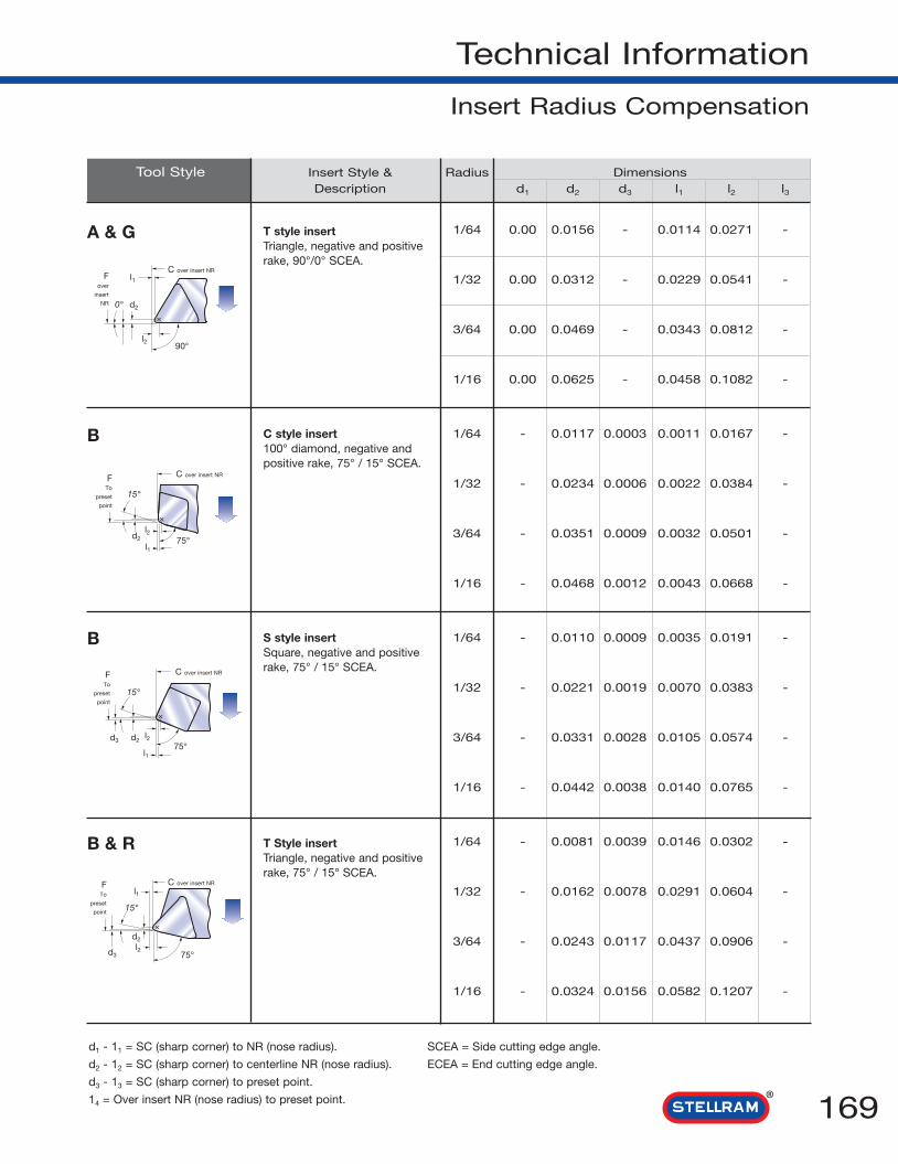
169
Technical Information
Insert Radius Compensation
X
A & G
d2
l1
l2
C over insert NRF
over
insert
NR 0°
90°
X
X
X
B
d2
l1
l2
C over insert NRFTo
preset
point
15°
d3 d2
l1
l2
C over insert NRFTo
preset
point
15°
d3
d2
l1
l2
C over insert NRFTo
preset
point 15°
75°
75°
75°
Tool Style Insert Style & Radius DimensionsDescription d1 d2 d3 l1 l2 l3
1/64 0.00 0.0156 - 0.0114 0.0271 -
1/32 0.00 0.0312 - 0.0229 0.0541 -
3/64 0.00 0.0469 - 0.0343 0.0812 -
1/16 0.00 0.0625 - 0.0458 0.1082 -
1/64 - 0.0117 0.0003 0.0011 0.0167 -
1/32 - 0.0234 0.0006 0.0022 0.0384 -
3/64 - 0.0351 0.0009 0.0032 0.0501 -
1/16 - 0.0468 0.0012 0.0043 0.0668 -
1/64 - 0.0110 0.0009 0.0035 0.0191 -
1/32 - 0.0221 0.0019 0.0070 0.0383 -
3/64 - 0.0331 0.0028 0.0105 0.0574 -
1/16 - 0.0442 0.0038 0.0140 0.0765 -
1/64 - 0.0081 0.0039 0.0146 0.0302 -
1/32 - 0.0162 0.0078 0.0291 0.0604 -
3/64 - 0.0243 0.0117 0.0437 0.0906 -
1/16 - 0.0324 0.0156 0.0582 0.1207 -
T style insertTriangle, negative and positiverake, 90°/0° SCEA.
C style insert100° diamond, negative andpositive rake, 75° / 15° SCEA.
S style insertSquare, negative and positiverake, 75° / 15° SCEA.
T Style insertTriangle, negative and positiverake, 75° / 15° SCEA.
d1 - 11 = SC (sharp corner) to NR (nose radius). SCEA = Side cutting edge angle.
d2 - 12 = SC (sharp corner) to centerline NR (nose radius). ECEA = End cutting edge angle.
d3 - 13 = SC (sharp corner) to preset point.
14 = Over insert NR (nose radius) to preset point.
B & R
B

E
F
Tool Style Insert Style & Radius DimensionsDescription d1 d2 d3 l1 l2 l3
1/64 0.0114 0.0271 - 0.0156 - -
1/32 0.0229 0.0541 - 0.0312 - -
3/64 0.0343 0.0812 - 0.0469 - -
1/16 0.0458 0.1082 - 0.0625 - -
1/64 - 0.00 0.0065 0.0065 0.0221 -
1/32 - 0.00 0.0129 0.0129 0.0442 -
3/64 - 0.00 0.0194 0.0194 0.0663 -
1/16 - 0.00 0.0658 0.0658 0.0884 -
1/64 - 0.00 0.0090 0.0156 0.0312 -
1/32 - 0.00 0.0180 0.0312 0.0625 -
3/64 - 0.00 0.0270 0.0469 0.0938 -
1/16 - 0.00 0.0361 0.0625 0.1250 -
1/64 0.0030 0.0186 - 0.00 0.396 -
1/32 0.0060 0.0372 - 0.00 0.0312 -
3/64 0.0090 0.0559 - 0.00 0.0469 -
1/16 0.0120 0.0745 - 0.00 0.0625 -
T Style insertTriangle, negative and positiverake, 90° / 0’ ECEA.
S style insertSquare, negative and positiverake, 45° / 45° ECEA andSCEA.
T style insertTriangle, negative and positiverake, 60° / 30° SCEA.
C style insert80° diamond, negativeand positive rake,90° / 0° ECEA.
170
Technical Information
Insert Radius Compensation
X
X
d2 d3
l2
l1
C over insert NRFSC
insert
30°
d1 d2l1
l2
C over insert NRFover
insert
NR
90°
60°
0°
d1 - 11 = SC (sharp corner) to NR (nose radius). SCEA = Side cutting edge angle.
d2 - 12 = SC (sharp corner) to centerline NR (nose radius). ECEA = End cutting edge angle.
d3 - 13 = SC (sharp corner) to preset point.
14 = Over insert NR (nose radius) to preset point.
D & S
X
d2 d3 l2
l1
C over insert NRF
over
insert
NR
45°
45°
X
d1 d2
l2
C over insert NRF
over
insert
NR
90°
0°
l1
C & F

171
Technical Information
Insert Radius Compensation
G
J
J
Tool Style Insert Style & Radius Dimensions
Description d1 d2 d3 l1 l2 l3
1/64 0.00 0.0156 - 0.0030 0.0186 -
1/32 0.00 0.0312 - 0.0060 0.0312 -
3/64 0.00 0.0469 - 0.0090 0.0559 -
1/16 0.00 0.0625 - 0.0120 0.0745 -
1/64 0.0014 0.0170 - 0.0106 0.0262 -
1/32 0.0028 0.0340 - 0.0212 0.0524 -
3/64 0.0042 0.0511 - 0.0318 0.0786 -
1/16 0.1422 0.0681 - 0.0423 0.1048 -
1/64 0.0015 0.0172 - 0.0135 0.0292 -
1/32 0.0031 0.0343 - 0.0271 0.0583 -
3/64 0.0046 0.0519 - 0.0406 0.0875 -
1/16 0.0062 0.0687 - 0.0541 0.1166 -
1/64 0.0026 0.0182 - 0.0330 0.0487 -
1/32 0.0051 0.0364 - 0.0661 0.0973 -
3/64 0.0077 0.0546 - 0.0991 0.1460 -
1/16 0.0103 0.0728 - 0.1322 0.1947 -
C style insert80° diamond, negativeand positive rake,90° / 0° ECEA.
T style insertTriangle, negative and positiverake, 93° / 3° rev. SCEA.
D style insert55° diamond, negative andpositive rake, 93° / 3° rev.SCEA.
V style insert35° diamond, negativeand positive rake,93° / 3° rev. SCEA.
J
X
X
d1
d2
l1
l2
C over insert NRF
over
insert
NR
0°
d2
C over insert NRF
over
insert
NR
90°
93°
X
X
d2
l1
l2
C over insert NR
Fover
insert
NR
3°d1
d2
l1
l2
Fover
insert
NR
3°d1
C over
insert
NR
93°
93°
d1 - 11 = SC (sharp corner) to NR (nose radius). SCEA = Side cutting edge angle.
d2 - 12 = SC (sharp corner) to centerline NR (nose radius). ECEA = End cutting edge angle.
d3 - 13 = SC (sharp corner) to preset point.
14 = Over insert NR (nose radius) to preset point.

172
Technical Information
Insert Radius Compensation
L
L
Tool Style Insert Style & Radius DimensionsDescription d1 d2 d3 l1 l2 l3
1/64 0.0016 0.0172 - 0.0016 0.0172 -
1/32 0.0031 0.0344 - 0.0031 0.0344 -
3/64 0.0047 0.0516 - 0.0047 0.0516 -
1/16 0.0062 0.0688 - 0.0062 0.0688 -
1/64 0.0016 0.0172 - 0.0016 0.0172 -
1/32 0.0031 0.0344 - 0.0031 0.0344 -
3/64 0.0047 0.0516 - 0.0047 0.0516 -
1/16 0.0062 0.0688 - 0.0062 0.0688 -
C style insert80° diamond, negativeand positive rake, 95° / 5° rev.ECEA and SCEA.
W style insert80° trigon, negativeand positive rake,95° / 5° rev. ECEA and SCEA.
X
d1
d2
l1l2
Fover
insert
NR
C over insert NR
5°95°
X
d1
d2
l1l2
Fover
insert
NR
5°
C over insert NR
95°
K
K
Tool Style Insert Style & Radius DimensionsDescription
d1 d2 l2 l3
1/64 0.0035 0.0191 0.0110 0.0009
1/32 0.0070 0.0383 0.0221 0.0019
3/64 0.0105 0.0574 0.0331 0.0028
1/16 0.0140 0.0765 0.0442 0.0038
1/64 0.0011 0.0167 0.0117 0.003
1/32 0.0022 0.0334 0.0234 0.0006
3/64 0.0032 0.0501 0.0351 0.0009
1/16 0.0043 0.0668 0.0468 0.0012
X
X
d1 d2
l3l2
Fover
insert
NR
15°C over insert NR
l4
d1
Fover
insert
NR
15°
d2l2
C over insert NR
75°
75°
l3l4
d1 - 11 = SC (sharp corner) to NR (nose radius). SCEA = Side cutting edge angle.
d2 - 12 = SC (sharp corner) to centerline NR (nose radius). ECEA = End cutting edge angle.
d3 - 13 = SC (sharp corner) to preset point.
14 = Over insert NR (nose radius) to preset point.
S style insertSquare, negativeand positive rake,75° / 15° rev.ECEA.
C style insert80° diamond,negativeand positive rake,75° / 15° rev.ECEA.

173
Grooving

K
P
High TemperatureAlloys
Aluminum & Alloys
Cast Irons
Stainless Steels
Unalloyed andAlloyed Steels
M
N
S
CoatedCode GRADE
SFZMaterials C ISO
C8 P01
P05
P10
C7 P15
P20
P25
C6 P30
P35
C5 P40
P45
P50
M05
M10
M15
M20
M25
M30
M35
M40
C4 K01
K05
C3 K10
K15
C2 K20
K25
C1 K30
K35
K40
N01
N05
N10
N15
N20
N25
N30
S01
S05
S10
S15
S20
S25
S30
Grooving
174
RmISO Material and
Hardness
Incr
easi
ng -
sho
ck r
esis
tanc
e -
Incr
easi
ng -
fee
dIn
crea
sing
, w
ear
resi
stan
ce -
Incr
easi
ng c
uttin
g sp
eed
Optimum Grade PerformanceGrooving Grade Descriptions
• SFZ – A TiN PVD coated grade with amicrograin substrate for machining athigher speeds with lower feed. Ideal forstainless steels and ductile materials.
UnalloyedSteelsP
MStainless
Steels
Cast Irons
K
N
Aluminum& Alloys
Aluminium& Silicon
SHigh
Temperature
Alloys
Cutting Speed (Vc) SFM
SFZMax - Min
Max - Min
600 N/mm2890 445
180HBN
Austenitic + Ferritic- -
300 series
Martensitic- -
400 series
Refractory330 165
P.H.
Grey- -
GG-Ft
Spheroidal-Ductile- -
GGG-FGS
Malleable- -
GTS - MN/MP
< 16% Si 116HBN 2950 1180
> 16% Si 92HBN 2000 785
Iron Based 130 65
Cobalt Based 100 50
Nickel Based 115 65
Titanium Based 180 80

175
Ultra-Mini Grooving & Boring Toolholders
645 - 676
Description Dimensions (inch)a d e l1 h1 h2
6455000D 0.500 2.188 0.406 3.000 0.157 0.196
6456250D 0.625 2.188 0.406 3.000 0.157 0.196
6766250D 0.625 2.188 0.406 3.000 0.236 0.275
645 - 676
For Inserts refer to pages 176 - 180
Part Number Screw Pin
6455000D to 6766250D 110.640 111.645
SPARES
D
645
676

Ultra-Mini Grooving & Boring Toolholders
176
050...
Description Dimensions (inch) Toolholderb f a l l1 tmax Min. Bore ø ø style
R050310 - 0.023 0.102 0.944 0.393 0.007 0.110 0.157 645…
R050316 - 0.023 0.102 1.180 0.629 0.007 0.110 0.157 645…
R050320 - 0.023 0.102 1.340 0.787 0.007 0.110 0.157 645…
R050410 - 0.059 0.137 0.944 0.393 0.011 0.157 0.157 645…
R050416 - 0.059 0.137 1.180 0.629 0.011 0.157 0.157 645…
R050420 - 0.059 0.137 1.340 0.787 0.011 0.157 0.157 645…
R050510 - 0.074 0.173 0.984 0.393 0.019 0.196 0.196 645…
R050515 - 0.074 0.173 1.180 0.590 0.019 0.196 0.196 645…
R050520 - 0.074 0.173 1.380 0.787 0.019 0.196 0.196 645…
R050525 - 0.074 0.173 1.570 0.984 0.019 0.196 0.196 645…
R050530 - 0.074 0.173 1.770 1.180 0.019 0.196 0.196 645…
R050615 - 0.090 0.208 1.180 0.590 0.019 0.236 0.236 676…
R050622 - 0.090 0.208 1.460 0.866 0.019 0.236 0.236 676…
R050625 - 0.090 0.208 1.570 0.984 0.019 0.236 0.236 676…
R050630 - 0.090 0.208 1.770 1.180 0.019 0.236 0.236 676…
R050720 - 0.106 0.248 1.380 0.787 0.023 0.267 0.275 676…
R050725 - 0.106 0.248 1.570 0.984 0.023 0.267 0.275 676…
R050730 - 0.106 0.248 1.770 1.180 0.023 0.267 0.275 676…
050...
Min. BoreDia.
0,2rad.
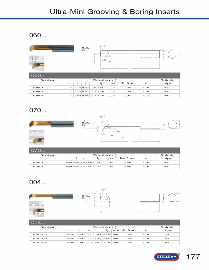
177
Ultra-Mini Grooving & Boring Inserts
060...
Description Dimensions (inch) Toolholderb f a l l1 tmax Min. Bore ø ø style
R060515 - 0.074 0.173 1.181 0.590 0.027 0.196 0.196 645…
R060520 - 0.074 0.173 1.377 0.787 0.027 0.196 0.196 645…
R060720 - 0.106 0.248 1.377 0.787 0.027 0.267 0.275 676…
060...
Min. BoreDia.
070...
Description Dimensions (inch) Toolholderb f a l l1 tmax Min. Bore ø ø style
R070515 0.039 0.074 0.173 1.181 0.590 0.007 0.196 0.196 645…
R070520 0.039 0.074 0.173 1.377 0.787 0.007 0.196 0.196 645…
070...
Min. BoreDia.
004...
Description Dimensions (inch) Toolholderb f a l l1 tmax Min. Bore ø ø style
R004010010 0.039 0.059 0.137 0.944 0.393 0.031 0.157 0.157 645…
R004010016 0.039 0.059 0.137 1.180 0.629 0.031 0.157 0.157 645…
R004010020 0.039 0.059 0.137 1.340 0.787 0.031 0.157 0.157 645…
004...
Min. BoreDia.

Ultra-Mini Grooving & Boring Inserts
178
005...
Description Dimensions (inch) Toolholderb f a l l1 tmax Min. Bore ø ø style
R005010010 0.039 0.074 0.173 0.984 0.393 0.039 0.196 0.196 645…
R005010015 0.039 0.074 0.173 1.180 0.590 0.039 0.196 0.196 645…
R005010020 0.039 0.074 0.173 1.380 0.787 0.039 0.196 0.196 645…
R005010025 0.039 0.074 0.173 1.570 0.984 0.039 0.196 0.196 645…
R005010030 0.039 0.074 0.173 1.770 1.180 0.039 0.196 0.196 645…
R005015010 0.059 0.074 0.173 0.984 0.393 0.039 0.196 0.196 645…
R005015015 0.059 0.074 0.173 1.180 0.590 0.039 0.196 0.196 645…
R005015020 0.059 0.074 0.173 1.380 0.787 0.039 0.196 0.196 645…
R005015025 0.059 0.074 0.173 1.570 0.984 0.039 0.196 0.196 645…
R005015030 0.059 0.074 0.173 1.770 1.180 0.039 0.196 0.196 645…
R005020010 0.078 0.074 0.173 0.984 0.393 0.039 0.196 0.196 645…
R005020015 0.078 0.074 0.173 1.180 0.590 0.039 0.196 0.196 645…
R005020020 0.078 0.074 0.173 1.380 0.787 0.039 0.196 0.196 645…
R005020025 0.078 0.074 0.173 1.570 0.984 0.039 0.196 0.196 645…
R005020030 0.078 0.074 0.173 1.770 1.180 0.039 0.196 0.196 645…
005...
006...
Description Dimensions (inch) Toolholderb f a l l1 tmax Min. Bore ø ø style
R006010010 0.039 0.090 0.208 0.984 0.393 0.070 0.236 0.236 676…
R006010015 0.039 0.090 0.208 1.180 0.590 0.070 0.236 0.236 676…
R006010022 0.039 0.090 0.208 1.460 0.866 0.070 0.236 0.236 676…
R006010025 0.039 0.090 0.208 1.570 0.984 0.070 0.236 0.236 676…
R006010030 0.039 0.090 0.208 1.770 1.180 0.070 0.236 0.236 676…
R006015010 0.059 0.090 0.208 0.984 0.393 0.070 0.236 0.236 676…
R006015015 0.059 0.090 0.208 1.180 0.590 0.070 0.236 0.236 676…
R006015022 0.059 0.090 0.208 1.460 0.866 0.070 0.236 0.236 676…
R006015025 0.059 0.090 0.208 1.570 0.984 0.070 0.236 0.236 676…
R006015030 0.059 0.090 0.208 1.770 1.180 0.070 0.236 0.236 676…
R006020010 0.078 0.090 0.208 0.984 0.393 0.070 0.236 0.236 676…
R006020015 0.078 0.090 0.208 1.180 0.590 0.070 0.236 0.236 676…
R006020022 0.078 0.090 0.208 1.460 0.866 0.070 0.236 0.236 676…
R006020025 0.078 0.090 0.208 1.570 0.984 0.070 0.236 0.236 676…
R006020030 0.078 0.090 0.208 1.770 1.180 0.070 0.236 0.236 676…
006...
Min. BoreDia.
Min. BoreDia.

179
Ultra-Mini Grooving & Boring Inserts
007...
Description Dimensions (inch) Toolholderb f a l l1 tmax Min. Bore ø ø style
R007010010 0.039 0.106 0.248 0.984 0.393 0.098 0.267 0.275 676…
R007010015 0.039 0.106 0.248 1.180 0.590 0.098 0.267 0.275 676…
R007010022 0.039 0.106 0.248 1.460 0.866 0.098 0.267 0.275 676…
R007010025 0.039 0.106 0.248 1.570 0.984 0.098 0.267 0.275 676…
R007010030 0.039 0.106 0.248 1.770 1.180 0.098 0.267 0.275 676…
R007015010 0.059 0.106 0.248 0.984 0.393 0.098 0.267 0.275 676…
R007015015 0.059 0.106 0.248 1.180 0.590 0.098 0.267 0.275 676…
R007015022 0.059 0.106 0.248 1.460 0.866 0.098 0.267 0.275 676…
R007015025 0.059 0.106 0.248 1.570 0.984 0.098 0.267 0.275 676…
R007015030 0.059 0.106 0.248 1.770 1.180 0.098 0.267 0.275 676…
R007020010 0.078 0.106 0.248 0.984 0.393 0.098 0.267 0.275 676…
R007020015 0.078 0.106 0.248 1.180 0.590 0.098 0.267 0.275 676…
R007020022 0.078 0.106 0.248 1.460 0.866 0.098 0.267 0.275 676…
R007020025 0.078 0.106 0.248 1.570 0.984 0.098 0.267 0.275 676…
R007020030 0.078 0.106 0.248 1.770 1.180 0.098 0.267 0.275 676…
007...
Min. BoreDia.

Ultra-Mini Grooving & Boring Inserts
180
004/5/6/7
Description Dimensions (inch) ToolholderTPI Pitch e f a l l1 t Min. Bore ø ø style
Medium Pitch
R005051015 24 0.039 0.022 0.074 0.173 1.180 0.590 0.021 0.188 0.196 645…
R006061215 20 0.049 0.025 0.090 0.208 1.180 0.590 0.026 0.236 0.236 676…
R006081515 16 0.059 0.029 0.090 0.208 1.180 0.590 0.031 0.236 0.236 676…
R007081515 16 0.059 0.029 0.106 0.248 1.180 0.590 0.031 0.275 0.275 676…
Fine Pitch
R004020515 50 0.019 0.014 0.059 0.137 1.180 0.590 0.010 0.157 0.157 645…
R005020515 50 0.019 0.014 0.074 0.173 1.180 0.590 0.010 0.196 0.196 645…
R005040715 32 0.029 0.018 0.074 0.173 1.180 0.590 0.015 0.196 0.196 645…
R006051015 24 0.039 0.022 0.090 0.208 1.180 0.590 0.021 0.236 0.236 676…
005/6/7..
Min. BoreDia.
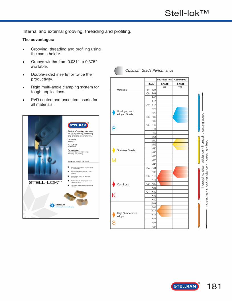
Unalloyed andAlloyed Steels
Stainless Steels
High TemperatureAlloys
Cast Irons
S
K
M
P
UnCoated PVD Coated PVD
Code GRADE GRADE
HA TP21Materials C ISO
C8 P01
P05
P10
C7 P15
P20
P25
C6 P30
P35
C5 P40
P45
P50
M05
M10
M15
M20
M25
M30
M35
M40
C4 K01
K05
C3 K10
K15
C2 K20
K25
C1 K30
K35
K40
S01
S05
S10
S15
S20
S25
S30
181
Stell-lok™
Internal and external grooving, threading and profiling.
Incr
easi
ng -
sho
ck r
esis
tanc
e -
Incr
easi
ng -
fee
dIn
crea
sing
, w
ear
resi
stan
ce -
Incr
easi
ng c
uttin
g sp
eed
Optimum Grade Performance
The advantages:
• Grooving, threading and profiling usingthe same holder.
• Groove widths from 0.031" to 0.375"available.
• Double-sided inserts for twice theproductivity.
• Rigid multi-angle clamping system fortough applications.
• PVD coated and uncoated inserts forall materials.
Stellram® tooling systemsfor your grooving, threadingand profiling requirements.
The tooling.Stell-lok™.
The material.All materials.
The application.Internal and external grooving,threading and profiling.
THE ADVANTAGES
Grooving, threading and profiling usingthe same holder.
Groove widths from 0.031” to 0.375”available.
Double-sided inserts for twice theproductivity.
Rigid multi-angle clamping system fortough applications.
PVD coated and uncoated inserts for allmaterials.
STELL-LOK™

Stell-lok™ Insert Identification System
182
1 Type of Insert
FN G P 301 2 3 4
2 Style of Insert
4 Insert Size
5 Width of Insert Groove
885
R6
FN - Stell-lok™ System
A - Acme
B - Blank (for specialforms; groundall overexcept notch)
D - Threading(drilling industry)
F - Face Grooving
G - Grooving
J - UNJ thread(controlled root radius)
P - Profile
R - Full Radius
V - Poly Vee
T - Threading
3 Style of Insert (additional Information)B - Buttress
F - Fine Pitch
S - Stub
C - Crest Grooving
P - Positive
K - Fine Pitch, Positive
R - Stellram® blank only
23456
Position pertains to groove width and radii in .001increments for F, G and R style grooving inserts.(e.g; 1/32" wide groove or radius equals .031 catalogposition number).
Position pertains to controlled root radii in .001increments on FNJ, FNJF, FNJP, FNJK style inserts.
6 Hand of InsertL - Left
R - Right
4 - 3* - 2.7294.5 - 2 7/8* - 2.6345 - 2 3/4 - 2.5346 1 7/8 2 1/2 1.695 2.3207 1 3/4 2 1/4 1.595 2.0958 1 5/8 2 1.490 1.8659 1 9/16 1 15/16 1.442 1.81710 1 1/2 1 7/8 1.392 1.76711 1 7/16 1 13/16 1.339 1.71411.5 1 3/8 1 3/4 1.281 1.65612 1 3/8 1 3/4 1.285 1.66013 1 5/16 1 5/8 1.229 1.54214 1 1/4 1 9/16 1/173 1.48516 1 1/4 1 9/16 1.173 1.48518 1 1/8 - 1.065 -20 1 1/8 - 1.071 -24 1 1/16*** - 1.017 -
TPI Nominal thread size Minimum minor diameter
FN-2 FN-3 & 4 FN-2 FN-3 & 4
* FN-4 insert only
** 16 TPI and finer can be cut as long as theminor diameter is 1.370 or larger
*** 24 TPI and finer can be cut with a FN-2 insertif the minor diameter is 1.00 or larger
FNT2 0.113 0.075 20-7 TPI 36-8 TPI 1.25-3.50 0.70-3.00FNTF2 0.062 0.040 24-12 TPI 44-14 TPI 1.00-2.00 0.60-1.75FNT3 0.148 0.097 12-5 TPI 20-6 TPI 2.00-5.00 1.25-4.00FNTF3 0.083 0.054 24-9 TPI 44-10 TPI 1.00-2.50 0.60-2.50FNTP3 0.148 0.097 12-5 TPI 20-6 TPI 2.00-5.00 1.25-4.00FNT4 0.196 0.127 12-4 TPI 20-4 TPI 2.00-6.25 1.25-6.25FNTP4 *0.196 0.127 12-4 TPI 20-4 TPI 2.00-6.25 1.25-6.25
Recommended threadRecommended TPI pitch-metricInsert Depth (D) Width (W) Internal External Internal External
* Only available in right hand insert
Threadsper inch
minimum minordiameter
(minimum bore)
nominal threadsize
(major diameter)
Internal Threading Limitationsfor FNT, FNTF and FNTP
60º V-Thread Application Data

183
Stell-lok™ Inserts
Left Hand Inserts
55°
E
3°
R
R
W
A
T
Description
FNG2031L
FNG2041L
FNG2047L
FNG2058L
FNG2062L
FNG2094L
FNG2125L
FNG3047L
FNG3062L
FNG3072L
FNG3078L
FNG3088L
FNG3094L
FNG3097L
FNG3105L
FNG3110L
FNG3122L
FNG3125L
FNG3142L
FNG3156L
FNG3178L
FNG3185L
FNG3189L
FNG4125L
FNG4189L
FNG4213L
FNG4219L
FNG4250L
FNG5250L
FNG5281L
FNG5312L
FNG5375L
FNG6281L
FNG6312L
FNG6344L
FNG6375L
Right Hand Inserts
The left hand inserts table includes the same R, W, T, E, A information as the right hand inserts table.
FNG
Description R W T E A
FNG2031R .002/.005 0.031 0.150 0.050 0.219
FNG2041R .002/.005 0.041 0.150 0.050 0.219
FNG2047R .002/.005 0.047 0.150 0.050 0.219
FNG2058R .005/.010 0.058 0.150 0.050 0.219
FNG2062R .005/.010 0.062 0.150 0.110 0.219
FNG2094R .005/.010 0.094 0.150 0.110 0.219
FNG2125R .005/.010 0.125 0.150 0.110 0.219
FNG3047R .005/.010 0.047 0.195 0.075 0.344
FNG3062R .005/.010 0.062 0.195 0.094 0.344
FNG3072R .005/.010 0.072 0.195 0.094 0.344
FNG3078R .005/.010 0.078 0.195 0.094 0.344
FNG3088R .005/.010 0.088 0.195 0.094 0.344
FNG3094R .005/.010 0.094 0.195 0.150 0.344
FNG3097R .010/.015 0.097 0.195 0.150 0.344
FNG3105R .005/.010 0.105 0.195 0.150 0.344
FNG3110R .010/.015 0.110 0.195 0.150 0.344
FNG3122R .005/.010 0.122 0.195 0.150 0.344
FNG3125R .005/.010 0.125 0.195 0.150 0.344
FNG3142R .010/.015 0.142 0.195 0.150 0.344
FNG3156R .005/.010 0.156 0.195 0.150 0.344
FNG3178R .005/.010 0.178 0.195 0.150 0.344
FNG3185R .020/.025 0.185 0.195 0.150 0.344
FNG3189R .020/.025 0.189 0.195 0.150 0.344
FNG4125R .005/.010 0.125 0.255 0.150 0.453
FNG4189R .020/.025 0.189 0.255 0.250 0.453
FNG4213R .005/.010 0.213 0.255 0.250 0.453
FNG4219R .020/.025 0.219 0.255 0.250 0.453
FNG4250R .020/.025 0.250 0.255 0.250 0.453
FNG5250R .020/.025 0.250 0.380 0.375 0.688
FNG5281R .030/.035 0.281 0.380 0.375 0.688
FNG5312R .030/.035 0.312 0.380 0.375 0.688
FNG5375R .030/.035 0.375 0.380 0.375 0.688
FNG6281R .030/.035 0.281 0.383 0.250 0.453
FNG6312R .030/.035 0.312 0.383 0.250 0.453
FNG6344R .030/.035 0.344 0.383 0.250 0.453
FNG6375R .030/.035 0.375 0.383 0.250 0.453

184
Stell-lok™ Inserts
Left Hand InsertsDescription
FNGP2031L
FNGP2062L
FNGP2125L
FNGP3088L
FNGP3125L
FNGP3156L
FNGP3189L
FNGP4189L
FNGP4250L
Right Hand Inserts
The left hand inserts table includes the same R, W, T, E, A information as the right hand inserts table.
Left Hand InsertsDescription R T D A
FNPR50.5 0.016 0.125 0.375 0.250
FNPR51 0.016 0.125 0.375 0.250
FNPR52 0.031 0.125 0.375 0.250
FNPR131F 0.016 0.188 0.500 0.375
FNPR331N 0.016 0.188 0.734 0.375
FNPR332N 0.031 0.188 0.734 0.375
Description
FNPL50.5
FNPL51
FNPL52
FNPL131F
FNPL331N
FNPL332N
Right Hand Inserts
The left hand inserts table includes the same R, T, D, A information as the right hand inserts table.
FNP
55°
T
A
W
R
R
3°E
55°
D
8°
R
10°
A
T
FNGP
Description R W T E A
FNGP2031R .002/.005 0.031 0.150 0.050 0.219
FNGP2062R .005/.010 0.062 0.150 0.110 0.219
FNGP2125R .005/.010 0.125 0.150 0.110 0.219
FNGP3088R .005/.010 0.088 0.195 0.094 0.344
FNGP3125R .005/.010 0.125 0.195 0.150 0.344
FNGP3156R .005/.010 0.156 0.195 0.150 0.344
FNGP3189R .020/.025 0.189 0.195 0.150 0.344
FNGP4189R .020/.025 0.189 0.255 0.250 0.453
FNGP4250R .020/.025 0.250 0.255 0.250 0.453

185
Stell-lok™ Inserts
Left Hand InsertsDescription
FNT2L
FNT3L
FNT4L
Right Hand Inserts
The left hand inserts table includes the same R, W, T, E, A information as the right hand inserts table.
Left Hand InsertsDescription
FNTF2L
FNTF3L
Right Hand Inserts
The left hand inserts table includes the same R, W, T, E, A information as the right hand inserts table.
FNTF
55°
E
60°
R
A
T
W
E
60°
55°
W
R
A
T
FNT
Description R W T E A
FNT2R .003/.005 0.075 0.150 .114@3° 0.219
FNT3R .005/.008 0.098 0.195 .146@3° 0.344
FNT4R .005/.008 0.128 0.255 .194@3° 0.453
Description R W T E A
FNTF2R .002/.004 0.110 0.150 .060@3° 0.219
FNTF3R .002/.004 0.141 0.195 .082@3° 0.344

Stell-lok™ Inserts
186
FNTP
Left Hand InsertsDescription
FNTP3L
FNTP4L
Right Hand Inserts
The left hand inserts table includes the same R, W, T, E, A information as the right hand inserts table.
WE
60°
55°
T
A
Description R W T E A
FNTP3R .005/.008 0.098 0.195 .146@3° 0.344
FNTP4R .005/.008 0.128 0.255 .194@3° 0.453
Left Hand InsertsDescription R T D A
FNR2031R 0.031 0.150 0.110 0.219
FNR2047R 0.047 0.150 0.110 0.219
FNR2062R 0.062 0.150 0.110 0.219
FNR3031R 0.031 0.195 0.094 0.344
FNR3047R 0.047 0.195 0.150 0.344
FNR3062R 0.062 0.195 0.150 0.344
FNR3078R 0.078 0.195 0.150 0.344
FNR3094R 0.094 0.195 0.150 0.344
FNR4062R 0.062 0.255 0.250 0.453
FNR4094R 0.094 0.255 0.250 0.453
FNR4125R 0.125 0.255 0.250 0.453
Description
FNR2031L
FNR2047L
FNR2062L
FNR3031L
FNR3047L
FNR3062L
FNR3078L
FNR3094L
FNR4062L
FNR4094L
FNR4125L
Right Hand Inserts
The left hand inserts table includes the same R, T, D, A information as the right hand inserts table.
FNR
55°
E
TR
A

187
Stell-lok™ Inserts
FNRP
Left Hand InsertsDescription R T E A
FNRP3031R 0.031 0.195 0.094 0.344
FNRP3047R 0.047 0.195 0.150 0.344
FNRP3062R 0.062 0.195 0.150 0.344
FNRP3078R 0.078 0.195 0.150 0.344
FNRP3094R 0.094 0.195 0.150 0.344
FNRP4062R 0.062 0.255 0.150 0.453
FNRP4094R 0.094 0.255 0.250 0.453
FNRP4125R 0.125 0.255 0.250 0.453
Description
FNRP3031L
FNRP3047L
FNRP3062L
FNRP3078L
FNRP3094L
FNRP4062L
FNRP4094L
FNRP4125L
Right Hand Inserts
The left hand inserts table includes the same R, T, E, A information as the right hand inserts table.
55°
A
R T
E
5°

188
Stell-lok™ Holder Identification System
1 Assembly Type
F N E L1 2 3 4
2 Insert
4 Tool Hand
5 & 6 Shank Size
165 & 6
37
F - Stell-lok™ Clamp
3 Toolholder Style
7 Insert Size
D8
N - Stell-lok™
AS - Side mount, no offset
E - OS-90 insert position to centerline of tool shank
S - OC - insert parallel to centerline of tool shank
06 - 3/8" sq.
08 - 1/2" sq.
10 - 5/8" sq.
12 - 3/4" sq.
16 - 1" sq.
20 - 1-1/4" sq.
24 - 1-1/2" sq.
2 - 2 series
3 - 3 series
4 - 4 series
5 - 5 series
6 - 6 series
L - LeftR - Right 8 Qualification Method & Length
Back to end
A - 4.000" long
B - 4.500" long
C - 5.000" long
D - 6.000" long
E - 7.000" long
F - 8.000" long
G - 5.500" long
H - 9.000" long
K - 12.000" long
L - 14.000" long
V - 3.500" long
Z - End only

189
Stell-lok™ Toolholders
FNAS
HG
E
B
C
F
B
Description Dimensions (inch) InsertB C E F H
FNASR/L-062 0.375 6.00 0.855 0.375 0.350 FN_2
FNASR/L-082 0.500 6.00 0.855 0.500 0.350 FN_2
FNASR/L-102 0.625 4.50 0.875 0.625 0.350 FN_2
FNASR/L-122 0.750 4.50 0.875 0.750 0.350 FN_2
FNAS
Part Number Clamp Clamp Screw
FNASL-062 to FNASL-082 CM183 #6-32x1/2SHCS
FNASR-062 to FNASR-082 CM182 #6-32x1/2SHCS
FNASL-102 to FNASL-122 CM75 #6-32x1/2SHCS
FNASR-102 to FNASR-122 CM74 #6-32x1/2SHCS
SPARES
RH Shown

190
Stell-lok™ Toolholders
FNE
Description Dimensions (inch) InsertB C H F
FNER/L-123B 0.750 4.50 2.00 1.125 FN_3
FNER/L-163D 1.000 6.00 2.00 1.250 FN_3
FNER-203D 1.250 6.00 2.00 1.500 FN_3
FNER-164D 1.000 6.00 2.00 1.375 FN_4
FNER-204D 1.250 6.00 2.00 1.625 FN_4
Use left-hand insert in right-hand tool; use right-hand insert in left-hand tool.
FNE
Part Number Clamp Clamp Screw
FNER-123B to FNER-204D CM73 #10-32X3/4SHCS
FNEL-123B to FNEL-163D CM72 #10-32X3/4SHCS
SPARES
F35°
B
C
B
H
RH Shown

191
Stell-lok™ Toolholders
FNS
E
B
F
C
B
Description Dimensions (inch) InsertB C E F
FNSR-122B 0.750 4.50 1.25 1.000 FN_2
FNSR-162C 1.000 5.00 0.75 1.250 FN_2
FNSR/L-123B 0.750 4.50 1.25 1.000 FN_3
FNSR/L-163D 1.000 6.00 1.25 1.250 FN_3
FNSR/L-203D 1.250 6.00 1.25 1.500 FN_3
FNSR/L-164D 1.000 6.00 1.38 1.250 FN_4
FNSR/L-204D 1.250 6.00 1.38 1.500 FN_4
FNSR/L-205D 1.250 6.00 2.00 1.500 FN_5
FNSR/L-166D 1.000 6.00 1.38 1.250 FN_6
FNSR/L-206D 1.250 6.00 1.38 1.500 FN_6
FNSR/L-246D 1.500 6.00 1.50 2.000 FN_6
FNS
Part Number Clamp Clamp Anvil AnvilScrew Screw
FNSR-122B to FNSR-162C CM74 #6-32X1/2SHCS - -
FNSR-123B to FNSR-203D CM73 #10-32X3/4SHCS - -
FNSL-123B to FNSL-204D CM72 #10-32X3/4SHCS - -
FNSR-164D to FNSR-203D CM73 #10-32X3/4SHCS SM420 SL-344
FNSL-164D to FNSL-204D CM72 #10-32X3/4SHCS SM420 SL-344
FNSR-205D CM81 5/1618X1SHCS - -
FNSL-205D CM80 5/1618X1SHCS - -
FNSR-206D to FNSR-246D CM120 #10-32X3/4SHCS SM416 440X3/8FHCS
FNSL-206D to FNSL-246D CM121 #10-32X3/4SHCS SM416 440X3/8FHCS
SPARES
RH Shown

Stell-lok™ Toolholders
192
S-FNE
3°
D
L
F
MIN.BORE
Description Dimensions (inch) InsertD L F Min. Bore
S10FNER2 0.625 10.00 0.500 1.00 FN_2
S16FNEL3F 1.000 8.00 0.688 1.37 FN_3
S16FNER3 1.000 8.00 0.688 1.37 FN_3
S20FNER3 1.250 14.00 0.875 1.75 FN_3
S24FNER3 1.500 14.00 1.000 2.00 FN_3
S32FNEL5 2.000 16.00 1.406 2.812 FN_5
S32FNER5 2.000 16.00 1.406 2.812 FN_5
S32FNEL6 2.000 16.00 1.375 2.75 FN_6
S32FNER6 2.000 16.00 1.375 2.75 FN_6
Use left-hand insert in right-hand tool; use right-hand insert in left-hand tool.
S-FNE
Part Number Clamp Clamp Screw
S10FNER2 CM75 #6-32X1/2SHCS
S16FNEL3F CM72 #10-32X3/4SHCS
S16FNER3 to S24FNER3 CM73 #10-32X3/4SHCS
S32FNEL5 CM80 5/1618X1SHCS
S32FNER5 CM81 5/1618X1SHCS
S32FNEL6 CM120 #10-32X3/4SHCS
S32FNER6 CM121 #10-32X3/4SHCS
SPARES
Min.Bore
RH Shown

193
Part-Off
Two part-off systems are available. The first is a block and blade system with Part-off widthsranging from 0.079" (2mm) to 0.236" (6mm). The second system is designed for SwissAutomatics with part-off ranges from 0.063" (1.6mm) to 0.118" (3mm). Both systems offerneutral, right and left-hand inserts.
Unalloyed andAlloyed Steels
Stainless Steels
Cast Irons
S
N
K
M
P
Incr
easi
ng -
sho
ck r
esis
tanc
e -
Incr
easi
ng -
fee
dIn
crea
sing
, w
ear
resi
stan
ce -
Incr
easi
ng c
uttin
g sp
eed
Coated CVD Coated PVD
Code GRADE GRADEMP91M SP3014
Materials C ISO
C8 P01
P05
P10
C7 P15
P20
P25
C6 P30
P35
C5 P40
P45
P50
M05
M10
M15
M20
M25
M30
M35
M40
C4 K01
K05
C3 K10
K15
C2 K20
K25
C1 K30
K35
K40
N01
N05
N10
N15
N20
N25
N30
S01
S05
S10
S15
S20
S25
S30
Optimum Grade Performance
Part-off Grade Description
• SP3014 – A TiAlN PVD coated gradeoffering with a sharp edge condition.Ideal for stainless steels and hightemperature alloys.
• MP91M – A TiN-TiCN-Al2O3 CVD coatedgrade offering good wear resistance.Ideal for steels and cast irons.
High
Temperature
Alloys
K
N
S
RmISO Material and
Hardness
P
UnalloyedSteels
AlloyedSteels
Aluminum& Alloys
Aluminum& Silicon
Cast Irons
Cutting Speed (Vc) SFM Coated
CVD PVDMP91M SP3014
Max - Min Max - Min
400 - 600 N/mm21150 460 1405 665
120 - 180HBN
600 - 950 N/mm2980 395 910 430
180 - 280HBN
700 - 950 N/mm2885 330 835 395
200 - 280 HBN
950 - 1200 N/mm2655 260 760 360
280 - 355 HBN
1200 - 1400 N/mm2- - 520 245
355 - 415 HBN
Austenitic + Ferritic655 395 950 450
300 series
Martensitic590 360 990 470
400 series
Refractory- - 505 240
P.H.
Grey1180 460 1395 660
GG-Ft
Spheroidal-Ductile920 360 1205 570
GGG-FGS
Malleable855 330 810 385
GTS - MN/MP
< 16% Si 116HBN - - 3150 1200
> 16% Si 92HBN - - - -
Iron Based - - 205 95
Cobalt Based - - 165 80
Nickel Based - - 175 85
Titanium Based - - 280 130
M
StainlessSteels
High TemperatureAlloys
Aluminum & Alloys

Part-Off Toolholders
194
Positive Stop Blades
Description Dimensionsh l Max. ø Inserts
SGIH26.2PSHD 1.006 4.372 3.000 TGT_2/2.4
SGIH26.3PSHD 1.006 4.372 3.000 TGT_3
SGIH26.4PSHD 1.006 4.372 3.000 TGT_4
SGIH26.5PSHD 1.006 4.372 3.000 TGT_4.8/5
SGIH32.3PSHD 1.225 5.942 4.000 TGT_3
SGIH32.4PSHD 1.225 5.942 4.000 TGT_4
SGIH32.5PSHD 1.225 5.942 5.000 TGT_4.8/5
SGIH32.6PSHD 1.225 5.942 5.000 TGT_6
SGIH
Part Number Extracting Wrench
SGIH26.2PSHD to SGIH32.6PSHD E219EXTKEY
SPARES
Tool Blocks
Description Dimensions Acceptsa b d e Blades
TGTBN195 0.075 0.750 1.500 1.438 SGIH26.2/3/4/5/6
TGTBN196 0.075 0.750 1.875 1.438 SGIH32.3/4/5/6
TGTBN255 1.000 0.780 1.500 1.469 SGIH26.2/3/4/5/6
TGTBN256 1.000 0.780 1.875 1.469 SGIH32.3/4/5/6
TGTBN326 1.250 1.125 1.875 1.813 SGIH32.3/4/5/6
TGTB

195
Part-Off Toolholders
N
Material Designations
High Temp. Alloys
Hard Materials
Cast Irons
Aluminum & Alloys
Stainless Steels
PH Stainless
Unalloyed Steels
Alloyed Steels
Star Guide Key to Recommended Inserts
P M K S
HMP
TGT Inserts
s
2°2°
Description MP91M s
TGTN2 ◆◆◆◆ 0.087
TGTN2.4 ◆◆◆◆ 0.094
TGTN3 ◆◆◆◆ 0.122
TGTR38 ◆◆◆◆ 0.122
TGTL38 ◆◆◆◆ 0.122
TGTN4 ◆◆◆◆ 0.161
TGTN4.8 ◆◆◆◆ 0.188
TGTN5 ◆◆◆◆ 0.200
TGTN6 ◆◆◆◆ 0.250
s
8°2°2°
TGTN,TGTR & TGTL
TGTN TGTR/L
Neutralinsert
LH insertshown
Mini Part-Off Toolholders
STPOR
Description Dimensions Max. Insertsb l1 l2 l3 h h1 Part-off ø Part-Off
STPOR-061.6 0.357 6.000 1.300 0.670 0.375 0.375 1.250 STT_1.6
STPOR-062.0/2.4 0.357 6.000 1.300 0.670 0.375 0.375 1.250 STT_2.0/2.4
STPOR-081.6 0.482 6.000 1.300 0.670 0.500 0.500 1.250 STT_1.6
STPOR-082.0/2.4 0.482 6.000 1.300 0.670 0.500 0.500 1.250 STT_2.0/2.4
STPOR-102.0/2.4 0.610 6.000 1.300 0.670 0.625 0.625 1.250 STT_2.0/2.4
STPOR-103.0 0.610 6.000 1.300 0.670 0.625 0.625 1.250 STT_3.0
STPOR-122.0/2.4 0.735 5.000 1.300 0.670 0.750 0.750 1.250 STT_2.0/2.4
STPOR-123.0 0.735 5.000 1.300 0.670 0.750 0.750 1.250 STT_3.0
STPOR
Part Number Screw Wrench
STPOR-061.6 to STPOR-123.0 F4015T T20
SPARES
NOTE: The part number for these tools are Stellram specific as ISO 5608 does not cater for this typeof tool. Available in RIGHT HAND only.
RH Shown

Mini Part-Off Inserts
196
STTN
l
Description s l
STTN1.6 0.062 0.393
STTN2.0 0.078 0.393
STTN2.4 0.094 0.393
STTN2.4CF 0.094 0.393
STTN3.0 0.118 0.393
STTN3.0CF 0.118 0.393
Grade SP3014 only applies to STT... CF inserts.
STTN
STTR & STTL
Description s l
STTR/L1.6 0.062 0.393
STTR/L2.0 0.078 0.393
STTR/L2.4 0.094 0.393
STTR2.405CF 0.094 0.393
STTR/L3.0 0.118 0.393
STTR3.005CF 0.118 0.393
Grade SP3014 only applies to STT... CF inserts.
STTR & STTL
Neutral insert shown
LH insert shown

197
Threading
Stellram’s comprehensive threading program is available in a wide range of thread forms.Partial and full profile inserts are offered for thread turning.
Stellram offers two high-performance grades suitable for all machining applications in awide range of materials for maximum productivity.
Stellram offers both external toolholders and internal bars with coolant holes; internalholders to a minimum bore of 0.157". Chatter free holders are available for difficultapplications.

Unalloyed andAlloyed Steels
Stainless Steels
Aluminum & Alloys
High TemperatureAlloys
Cast Irons
S
N
K
M
P
Coated PVDCode GRADE
SFZ SP4036Materials C ISO
C8 P01
P05
P10
C7 P15
P20
P25
C6 P30
P35
C5 P40
P45
P50
M05
M10
M15
M20
M25
M30
M35
M40
C4 K01
K05
C3 K10
K15
C2 K20
K25
C1 K30
K35
K40
N01
N05
N10
N15
N20
N25
N30
S01
S05
S10
S15
S20
S25
S30High
Temperature
AlloysS
Cast Irons
K
AlloyedSteels
StainlessSteels
Aluminum& Alloys
Aluminum& SiliconN
P
M
198
Threading
RmISO Material and
Hardness
Incr
easi
ng -
sho
ck r
esis
tanc
e -
Incr
easi
ng -
fee
dIn
crea
sing
, w
ear
resi
stan
ce -
Incr
easi
ng c
uttin
g sp
eed
Optimum Grade PerformanceThreading Grade Descriptions
• SFZ – A TiN PVD coated grade with amicrograin substrate for machining atlower speeds. Ideal for stainless steelsand ductile materials.
• SP4036 – A TiAlN PVD coated grade witha micrograin substrate offering hightemperature stability and a low coefficientof friction. Ideal for machining mostmaterials at higher speeds.
Cutting Speed (Vc) SFM PVD Coated
SFZ SP4036Max - Min Max - Min
Max - Min Max - Min
600 N/mm2890 445 1475 655
180HBN
950 N/mm2- - 950 425
280HBN
700 - 950 N/mm2- - 855 395
200 - 280 HBN
Austenitic + Ferritic- - 985 460
300 series
Martensitic- - 1015 490
400 series
Refractory330 165 525 245
P.H.
Grey- - 1445 655
GG-Ft
Spheroidal-Ductile- - 1245 590
GGG-FGS
Malleable- - 855 395
GTS - MN/MP
< 16% Si 116HBN 2950 1180 - -
> 16% Si 92HBN 2000 785 - -
Iron Based 130 65 215 100
Cobalt Based 100 50 165 80
Nickel Based 115 65 180 80
Titanium Based 180 80 290 130
UnalloyedSteels

199
Anvil Selection
With the Stellram threading system, a wide range of thread helix angles can be
obtained without changing or modifying toolholders. This is obtained by simply
changing the carbide anvil to one of correct angle.
Most toolholders are produced with 1.5° helix machined into the body. These tools
are supplied with this angle as standard.
Interchangeable anvils allow helix variations
between +4.5° and -1.5° with the insert cutting
edge remaining constant.
Negative helix angles are used for producing
right hand threads with left hand holders or left
hand threads with right hand holders.
ß Helix Angle
Insert size 4.5° 3.5° 2.5° 1.5° 0.5° 0° -0.5° -1.5°
mm Inch Toolholder Anvil Part Numbers
16 3/8"EX RH / IN LH YE33P YE32P YE31P YE3 YE31N YE31.5N YE32N YE33N
EX LH / IN RH YI33P YI32P YI31P YI3 YI31N YI31.5N YI32N YI33N
22 1/2"EX RH / IN LH YE43P YE42P YE41P YE4 YE41N YE41.5N YE42N YE43N
EX LH / IN RH YI43P YI42P YI41P YI4 YI41N YI41.5N YI42N YI43N
22U 1/2"EX RH / IN LH YE4U3P YE4U2P YE4U1P YE4U YE4U1N YE4U1.5N YE4U2N YE4U3N
EX LH / IN RH YI4U3P YI4U2P YI4U1P YI4U YI4U1N YI4U1.5N YI4U2N YI4U3N
27 5/8"EX RH / IN LH YE53P YE52P YE51P YE5 YE51N YE51.5N YE52N YE53N
EX LH / IN RH YI53P YI52P YI51P YI5 YI51N YI51.5N YI52N YI53N
27U 5/8"EX RH / IN LH YE5U3P YE5U2P YE5U1P YE5U YE5U1N YE5U1.5N YE5U2N YE5U3N
EX LH / IN RH YI5U3P YI5U2P YI5U1P YI5U YI5U1N YI5U1.5N YI5U2N YI5U3N
Note: Standard toolholders are supplied with 1.5° helix angle as standard.
Calculation of thread helix angle for a given thread
β β
1,5° Standard
Negative Helix
1,5° Standard
Helix angle - Tan-1 � = Lead of the thread
Pitch Diameter x π

200
Anvil Selection
φ 15° φ 10°
INTERNAL EXTERNAL
Flank Clearance Angle Selection
ω
ω 5.8° = 5.8°
ω 8.8° = 8.8°
2α = 60°
ω
ISOUNPARTIAL 60˚NPT
ω 2.6° = 2.6°
ω 4° = 4°
2α = 30°2α = 29°
ω ω
TRAPEZOIDALACMESTUB ACME
ω 5.8° = 0.5°
ω 8.8° = 0.8°
α = 30°
α = 3°
ω ω
SAGE (DIN 513)
ω 10° = 1,24°
ω 1.5° = 1.9°
α = 45°
α = 7°
ω ω
AMERICAN BUTTRESS

201
Helix Angle Calculation Tables
Outside Pitch
Diameter 1 1,25 1,5 1,75 2 3 4 5 6inch Helix Angle (Degrees and Minutes)
0.200 3° - 38´ 4° - 33´ 5° - 27´ - - - - - -
0.236 3° - 2´ 3° - 48´ 4° - 33´ 5° - 18´ 6° - 33´ - - - -
0.315 2° - 17´ 2° - 51´ 3° - 25´ 3° - 59´ 4° - 33´ 6° - 49´ - - -
0.395 1° - 49´ 2° - 16´ 2° - 44´ 3° - 11´ 3° - 39´ 5° - 27´ - - -
0.500 1° - 31´ 1° - 54´ 2° - 17´ 2° - 39´ 3° - 2´ 4° - 33´ - - -
0.550 1° - 18´ 1° - 38´ 1° - 57´ 2° - 17´ 2° - 36´ 3° - 54´ - - -
0.630 1° - 8´ 1° - 42´ 1° - 42´ 2° - 0´ 2° - 17´ 3° - 25´ - - -
0.710 1° - 1´ 1° - 16´ 1° - 31´ 1° - 46´ 2° - 2´ 3° - 2´ 4° - 3´ - -
0.790 55´ 1° - 8´ 1° - 22´ 1° - 36´ 1° - 49´ 2° - 44´ 3° - 39´ - -
1.000 44´ 55´ 1° - 6´ 1° - 16´ 1° - 28´ 2° - 11´ 2° - 55´ - -
1.180 36´ 46´ 55´ 1° - 4´ 1° - 13´ 1° - 49´ 2° - 26´ 3° - 2´ 3° - 39´
1.375 31´ 39´ 47´ 55´ 1° - 3´ 1° - 33´ 2° - 5´ 2° - 36´ 3° - 8´
1.575 27´ 34´ 41´ 48´ 55´ - 1° - 49´ 2° - 17´ 2° - 44´
1.750 24´ 30´ 36´ 43´ 48´ 1° - 13´ 1° - 37´ 2° - 2´ 2° - 26´
2.000 - - - 38´ 44´ 1° - 6´ 1° - 28´ 1° - 49´ 2° - 11´
2.350 - - - - 36´ 55´ 1° - 13´ 1° - 31´ 1° - 49´
2.750 - - 23´ - 31´ 47´ 1° - 3´ 1° - 18´ 1° - 34´
3.150 - - - - - 41´ 55´ 1° - 8´ 1° - 22´
3.50 - - - 21´ 24´ 36´ 48´ 1° - 1´ 1° - 13´
4.00 - - 17´ 19´ - 33´ - 55´ 1°- 6´
Calculation of thread helix angle for a given thread
Helix angle - Tan-1 � = Lead of the thread
Pitch Diameter x π

202
Thread Form Index
Partial Profile 60°
PAGE 206
P
55°
1:16
0,1373 P
0,9
602 P
0,1
600 P
0,6
403 P
0,1
600 P
90°
P
47,5°
0,1808 P
0,1808 P
1,1
363 P
0,2
682 P
0,2
682 P
0,6
P
P
80°
0,050 P0,107 P 0,107 P
0,1
07 P
P
60°
0,125 P0,1443 P 0,1
443 P
0,6
134 P
0,0
722 P
0,1
082 P
0,8
660 P
P
60°
0,125 P0,1443 P 0,1
44
3 P
0,6
13
4 P
0,0
72
2 P
0,1
08
2 P
0,8
66
0 P
P
0,1373 P
55°
0,1373 P
0,9
605 P
0,1
601 P
0,6
403 P
0,1
601 P P
60°
1:1690°
0,8
657 P
0,0
328 P
0,0
8 P
0,0
328 P
P
60°
1:1690°
0,8
657 P
0,0
328 P
0,0
8 P
0,0
328 P
P
60°
0,125 P 0,1
804 P
0,1804 P
0,1
082 P
0,5
774 P
0,0
902 P
0,2706P
0,8
660 P
P
60°
0,125 P 0,1
80
4 P
0,1804 P
0,1
08
2 P
0,5
77
4 P
0,0
90
2 P
0,2706P
0,8
66
0 P
60˚ 55˚
Nut
Screw
Nut
Screw
Nut
Screw
Nut
Axis of screw Taper
Nut
Axis of screw Taper
Nut
Axis of screw Taper
Nut
Screw
Nut
Screw
Nut
Screw
Nut
Screw
Nut
Screw
Nut
Screw
ISO, UN
Partial Profile 55°
PAGE 207
W, BSPT
ISO
PAGES 208 - 210
ISO
Unified
PAGES 211 - 213
UN
British StandardWhitworth
PAGES 214 - 216W
National TaperPipe Thread
NPT
National Taper PipeThread (Dryseal)
PAGES 219 - 220NPTF
British StandardPipe Taper Thread
BSPT
BritishAssociation
PAGE 222
BA
ACME
PAGE 223
ACME
STUB ACME
PAGE 224
STUBACME
Trapezoidal(DIN 103)
PAGE 225
TR
P
29°
1,9
334 P a
c
1/2
d1
1/2
d1
0,7
167 P
0,5
P0,7
167 P
1/2
d1
b
Nut
Screw
Pla
yP
lay
Pla
y
P
29°
a
b
c
1,9
334 P
0,8
167 P
0,8
167 P
0,3
P
1/2
d1
1/2
d1
1/2
d1
Pla
y
Pla
y
Pla
y
Nut
Screw
P
30°1,8
660 P
0,6
830 P
0,6
830 P
0,5
Pa
a
Nut
Screw
Round (DIN 405)
PAGE 226
RD
Panzer Gewinde(DIN 40430)
PAGE 227
PG
Unified J Form
PAGE 228
UNJ
Metric J Form
PAGE 229
MJ
P
30°
0,2560 P0,2385 P
0,2385 P
0,2211 P
1,8
660 P
0,6
830 P
0,6
830 P
0,0
5 P
0,0
5 P
0,0
5 PScrew
Nut
PAGES 217 - 218 PAGE 221

203
Thread Form Index
British ButtressBS1657
PAGE 230
BBUTT
American Buttress45/7°
PAGE 231
ABUTT
Buttress (SAGE)
Available byquotation
SAGE
API V0.038
PAGE 232
API 38
API V0.040
PAGE 232API 40
API V0.050
API 50
API V0.055
PAGE 232API 55
API V0.065 & PAC
API 65, PAC
API Casing &Tubing Round
PAGE 233
API RD
Extreme LineCasing
PAGE 235
ELC
Buttress Casing
PAGE 236
BUTT
VAM
PAGE 237Made under
license
VAM
PAGE 232 PAGES 232 - 234
P
60°
0,5
91
2 P
90°0,1 P
0,1
P1,27 P
0,06 P
0,8
640 P
0,1
728 P P 0,1666
60°
0,047
0,1
441
0,015 R
0,047
0,055
0,015 R
0,015 R
0,0
406
0,0
559
0,0
559
0,0
406
0,0
476
0,0
559
P
60°
0,1
72
3 P
0,5
89
2 P
0,1
P
0,8
61
5 P
0,06 P
0,1 P 90°
1,27 P
P
60°
0,6
260 P
0,1
198 P
0,1
198 P
0,1
27 m
m0,1
78 m
m0,0
51 m
m
90°
0,8
657 P
P
12°
0,3
7P
6°6°
B(NR)
10°
3°
1°47´
B(ER) B(NR)
10°3°
B(ER)
P
60°
0,1
P
0,8
61
5 P
0,1 P
0,075 P
1,1016 P
90°
0,5
89
2 P
0,1
72
3 P
Nut
Axis of screw
Nut
Axis of screw
Nut
Axis of screw
Nut
Axis of screw
Nut
Axis of screw
Nut
Axis of screw
Nut
Screw Parallel to taper
Nut
Screw Parallel to axis
P
45°
7° 1/2
d1
0,5
059 P
0,1
059 P
0,2
P 0,2
P
0,1
395 P
0,5
059 P
0,2
453 P
1/2
d1
Nut
Screw
Pla
y
Pla
y
P
45°
0,8
90
6 P
7° 1/2
d1
0,0
62
7
P
0,3
P
1/2
d1
1/2
d1
0,3
P
0,1632 P
0,1632 P
0,3
P
Pla
y
Pla
y
Pla
y
Nut
Screw
30°0,8
90
6 P
3°
1/2
d1
0,0
62
7
P
0,3
P 1/2
d1
1/2
d1
0,3
P
0,1632 P
0,1632 P
P
1/2
d1
Nut
Screw
Pla
yP
lay
Pla
y
Pla
yP
60°
0,4
87
3 P
90°
0,152 P
1,651 P
0,0
6 P
0,1
520 P
Nut
Axis of screw
NOTE: Other thread forms available by quotation.

204
Threading Insert Designation
1 Size
16 E R 201 2 3 4
L IC
mm Inch
06 5/32
08 3/16
11 1/4
16 3/8
22 1/2
22U 1/2U
27 5/8
27U 5/8U
2 Utilisation
E I U
External Internal Neutral
3 Design
L R
Left Hand Right Hand
4 Thread Pitch or TPI
Partial Profile 60° or 55°
Thread Pitchmm TPI
A 0,5 - 1,5 48 - 16
G 1,75 - 3 14 - 8
AG 0,5 - 3 48 - 8
N 3,5 - 5 7 - 5
Q 5,5 - 6 4 1/2 - 4
U (22) 5,5 - 8 4 1/2 - 3 1/4
U (27) 6,5 - 9 2 3/4 - 4
Full Profile
0,35 to 8,0 mm (72-3 T.P.I)
Pitch sizes stated on all
thread form part numbers
P
P
IC
L

205
Threading Insert Designation
5 Thread Form
UN5
-6
SP40367
60
55
ABUTT
ACME
API RD
API
BA
BBUTT
BSPT
BUTT
ELC
ISO
60°
55°
45°/7°
29°
60°
60°
47,5°
45°/7°
55°
3°/10°
12°
60°
60°
60°
60°
60°
80°
30°
3°/30°
29°
30°
60°
60°
3˚/10°
55°
Partial Profile
Full Profile
Full Profile
MJ
NPT
NPTF
PAC
PG
RD
SAGE
STACME
TR
UN
UNJ
VAM
W
6 Other
M T Z
Multi-tooth style andnumber of teeth
SC
Swarf controlstyle
7 Type of Grade
SFZ/SP4036 Coated PVD
For grade descriptions, refer to page: 220

60° partial profile
Right Hand Inserts Left Hand Inserts
U Style Inserts
The left hand inserts table includes the same size, pitch range, T.P.I range, nose radius and X, Y information as the right hand inserts table.
Right Hand Inserts Left Hand Inserts
U Style Inserts
206
Size Description Pitch T.P.I Nose X YRange Range Radius inch inch
inch
11 11ERA60 0.5 - 1.25 48 - 20 - 0.031 0.035
16 16ERA60 0.5 - 1.5 48 - 16 - 0.031 0.035
16ERG60 1.75 - 3.5 14 - 8 - 0.047 0.067
16ERAG60 0.5 - 3.0 48 - 8 - 0.047 0.067
22 22ERN60 3.5 - 5.0 7 - 5 - 0.067 0.098
27 27ERQ60 5.5 - 6.0 4.5 - 4 - 0.102 0.122
Size Description Pitch T.P.I Nose X YRange Range Radius inch inch
inch
22 22EILRU60 5.5 - 8.0 4.5 - 3.25 - 0.024 0.433
27 27EILRU60 6.5 - 9.0 4 - 2.75 - 0.039 0.539
Description
11ELA60
16ELA60
16ELG60
16ELAG60
22ELN60
27ELQ60
Size Description Pitch T.P.I Nose X YRange Range Radius inch inch
inch
6 06IRA60 0.5 - 1.25 48 - 20 - 0.024 0.024
8 08IRA60 0.5 - 1.5 48 - 16 - 0.024 0.028
11 11IRA60 0.5 - 1.5 48 - 16 - 0.031 0.035
16 16IRA60 0.5 - 1.5 48 - 16 - 0.031 0.035
16IRG60 1.75 - 3.0 14 - 8 - 0.047 0.067
16IRAG60 0.5 - 3.0 48 - 8 - 0.047 0.067
22 22IRN60 3.5 - 5.0 7 - 5 - 0.067 0.098
27 27IRQ60 5.5 - 6.0 4.5 - 4 - 0.102 0.122
Description
08ILA60
11ILA60
16ILA60
16ILG60
16ILAG6
22ILN60
27ILQ60
Size Description Pitch T.P.I Nose X YRange Range Radius inch inch
inch
8 08ILRU60 1.75 - 2.0 14 - 11 - 0.031 0.157
y
x
ic
l
External Partial Profile 60° FormFor Unified & I.S.O metric thread forms
Internal Partial Profile 60° FormFor Unified & I.S.O metric thread forms
60˚
y
x
l
ic
l
ic
x
y
y
x
l
ic

55° partial profile
207
Right Hand Inserts Left Hand Inserts
U Style Inserts
The left hand inserts table includes the same size, pitch range, T.P.I range, nose radius and X, Y information as the right hand inserts table.
Right Hand Inserts Left Hand Inserts
U Style Inserts
Size Description Pitch T.P.I Nose X YRange Range Radius inch inch
inch
11 11ERA55 0.5 - 1.5 48 - 16 - 0.031 0.035
16 16ERA55 0.5 - 1.5 48 - 16 - 0.031 0.035
16ERG55 1.75 - 3.0 14 - 8 - 0.047 0.067
16ERAG55 0.5 - 3.0 48 - 8 - 0.047 0.067
22 22ERN55 3.5 - 5.0 7 - 5 - 0.067 0.098
27 27ERQ55 5.5 - 6.0 4.5 - 4 - 0.102 0.122
Description
11ELA55
16ELA55
16ELG55
16ELAG55
22ELN55
27ELQ55
Size Description Pitch T.P.I Nose X YRange Range Radius inch inch
inch
22 22EILRU55 5.5 - 8.0 4.5 - 3.25 - 0.053 0.433
27 27EILRU55 6.5 - 9.0 4 - 2.75 - 0.047 0.539
Size Description Pitch T.P.I Nose X YRange Range Radius inch inch
inch
6 06IRA55 0.5 - 1.25 48 - 20 - 0.024 0.024
8 08IRA55 0.5 - 1.5 48 - 16 - 0.024 0.028
11 11IRA55 0.5 - 1.5 48 - 16 - 0.031 0.035
16 16IRA55 0.5 - 1.5 48 - 16 - 0.031 0.035
16IRG55 1.75 - 3.0 14 - 8 - 0.047 0.067
16IRAG55 0.5 - 3.0 48 - 8 - 0.047 0.067
22 22IRN55 3.5 - 5.0 7 - 5 - 0.067 0.098
27 27IRQ55 5.5 - 6.0 4.5 - 4 - 0.102 0.122
Description
-
08ILA55
11ILA55
16ILA55
16ILG55
16ILAG55
22ILN55
27ILQ55
Size Description Pitch T.P.I Nose X YRange Range Radius inch inch
inch
8 08ILRU55 1.75 - 2.0 14 - 11 - 0.031 0.157
External Partial Profile 55° FormFor British Standard Whitworth & BritishStandard Parallel Pipe
Internal Partial Profile 55° FormFor British Standard Whitworth & BritishStandard Parallel Pipe
55˚
y
x
ic
l
l
ic
x
y
y
x
l
ic
y
x
l
ic
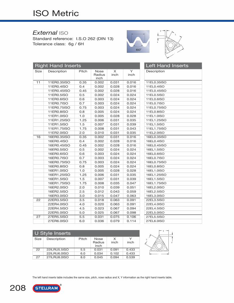
ISO Metric
Right Hand Inserts Left Hand Inserts
U Style Inserts
The left hand inserts table includes the same size, pitch, nose radius and X, Y information as the right hand inserts table.
208
Size Description Pitch Nose X YRadius inch inch
inch11 11ER0.35ISO 0.35 0.002 0.031 0.016
11ER0.4ISO 0.4 0.002 0.028 0.01611ER0.45ISO 0.45 0.002 0.028 0.01611ER0.5ISO 0.5 0.002 0.024 0.02411ER0.6ISO 0.6 0.003 0.024 0.02411ER0.7ISO 0.7 0.003 0.024 0.02411ER0.75ISO 0.75 0.003 0.024 0.02411ER0.8ISO 0.8 0.005 0.024 0.02411ER1.0ISO 1.0 0.005 0.028 0.02811ER1.25ISO 1.25 0.006 0.031 0.03511ER1.5ISO 1.5 0.007 0.031 0.03911ER1.75ISO 1.75 0.008 0.031 0.04311ER2.0ISO 2.0 0.010 0.031 0.035
16 16ER0.35ISO 0.35 0.002 0.031 0.01616ER0.4ISO 0.4 0.002 0.028 0.01616ER0.45ISO 0.45 0.002 0.028 0.01616ER0.5ISO 0.5 0.002 0.024 0.02416ER0.6ISO 0.6 0.003 0.024 0.02416ER0.7ISO 0.7 0.003 0.024 0.02416ER0.75ISO 0.75 0.003 0.024 0.02416ER0.8ISO 0.8 0.005 0.024 0.02416ER1.0ISO 1.0 0.005 0.028 0.02816ER1.25ISO 1.25 0.006 0.031 0.03516ER1.5ISO 1.5 0.007 0.031 0.03916ER1.75ISO 1.75 0.008 0.035 0.04716ER2.0ISO 2.0 0.010 0.039 0.05116ER2.5ISO 2.5 0.012 0.043 0.05916ER3.0ISO 3.0 0.015 0.047 0.063
22 22ER3.5ISO 3.5 0.018 0.063 0.09122ER4.0ISO 4.0 0.020 0.063 0.09122ER4.5ISO 4.5 0.023 0.067 0.09422ER5.0ISO 5.0 0.025 0.067 0.098
27 27ER5.5ISO 5.5 0.031 0.075 0.10627ER6.0ISO 6.0 0.036 0.079 0.114
Description
11EL0.35ISO
11EL0.4ISO
11EL0.45ISO
11EL0.5ISO
11EL0.6ISO
11EL0.7ISO
11EL0.75ISO
11EL0.8ISO
11EL1.0ISO
11EL1.25ISO
11EL1.5ISO
11EL1.75ISO
11EL2.0ISO
16EL0.35ISO
16EL0.4ISO
16EL0.45ISO
16EL1.5ISO
16EL0.6ISO
16EL0.7ISO
16EL0.75ISO
16EL0.8ISO
16EL1.0ISO
16EL1.25ISO
16EL1.5ISO
16EL1.75ISO
16EL2.0ISO
16EL2.5ISO
16EL3.0ISO
22EL3.5ISO
22EL4.0ISO
22EL4.5ISO
22EL5.0ISO
27EL5.5ISO
27EL6.0ISO
Size Description Pitch Nose X YRadius inch inch
inch22 22ILRU5.5ISO 5.5 0.031 0.091 0.433
22ILRU6.0ISO 6.0 0.034 0.102 0.43327 27ILRU8.0ISO 8.0 0.045 0.094 0.539
External ISOStandard reference: I.S.O 262 (DIN 13)Tolerance class: 6g / 6H
60˚
x
y
l
ic
ic
l
x
y

ISO Metric Continued..
209
Description
-
-
-
-
08IL0.5ISO
08IL0.75ISO
08IL1.0ISO
08IL1.25ISO
08IL1.5ISO
08IL1.75ISO
11IL0.35ISO
11IL0.4ISO
11IL0.45ISO
11IL0.5ISO
11IL0.6ISO
11IL0.7ISO
11IL0.75ISO
11IL0.8ISO
11IL1.0ISO
11IL1.25ISO
11IL1.5ISO
11IL1.75ISO
11IL2.0ISO
11IL2.5ISO
16IL0.35ISO
16IL0.4ISO
16IL0.45ISO
16IL0.5ISO
16IL0.6ISO
16IL0.7ISO
Right Hand Inserts Left Hand InsertsSize Description Pitch Nose X Y
Radius inch inchinch
6 06IR0.5ISO 0.5 0.001 0.024 0.020
06IR0.75ISO 0.75 0.001 0.024 0.020
06IR1.0ISO 1.0 0.002 0.024 0.024
06IR1.25ISO 1.25 0.003 0.024 0.028
8 08IR0.5ISO 0.5 0.001 0.024 0.020
08IR0.75ISO 0.75 0.001 0.024 0.020
08IR1.0ISO 1.0 0.002 0.024 0.024
08IR1.25ISO 1.25 0.003 0.024 0.028
08IR1.5ISO 1.5 0.004 0.024 0.040
08IR1.75ISO 1.75 0.004 0.024 0.040
11 11IR0.35ISO 0.35 0.001 0.031 0.012
11IR0.4ISO 0.4 0.001 0.031 0.016
11IR0.45ISO 0.45 0.001 0.031 0.016
11IR0.5ISO 0.5 0.001 0.024 0.024
11IR0.6ISO 0.6 0.001 0.024 0.024
11IR0.7ISO 0.7 0.001 0.024 0.024
11IR0.75ISO 0.75 0.001 0.024 0.024
11IR0.8ISO 0.8 0.002 0.024 0.024
11IR1.0ISO 1.0 0.002 0.024 0.028
11IR1.25ISO 1.25 0.003 0.031 0.031
11IR1.5ISO 1.5 0.003 0.031 0.040
11IR1.75ISO 1.75 0.004 0.031 0.040
11IR2.0ISO 2.0 0.005 0.031 0.043
11IR2.5ISO 2.5 0.006 0.031 0.051
16 16IR0.35ISO 0.35 0.001 0.031 0.012
16IR0.4ISO 0.4 0.001 0.031 0.016
16IR0.45ISO 0.45 0.001 0.031 0.016
16IR0.5ISO 0.5 0.001 0.024 0.024
16IR0.6ISO 0.6 0.001 0.024 0.024
16IR0.7ISO 0.7 0.001 0.024 0.024
The left hand inserts table includes the same size, pitch, nose radius and X, Y information as the right hand inserts table.
Multi ToothSize Description Pitch Nose X Y
Radius inch inchinch
16 16IR1.0ISO3M 1.0 0.005 0.067 0.10216IR1.5ISO2M 1.5 0.007 0.063 0.094
22 22IR1.5ISO3M 1.5 0.007 0.094 0.15022IR2.0ISO2M 2.0 0.010 0.079 0.11822IR2.0ISO3M 2.0 0.010 0.122 0.193
27 27IR3.0IS02M 3.0 0.015 0.106 0.169
Internal ISOStandard reference: I.S.O 262 (DIN 13)Tolerance class: 6g / 6H
l
ic
y
x
ic
l
y
x

ISO Metric Continued..
The left hand inserts table includes the same size, pitch, nose radius and X, Y information as the right hand inserts table.
U Style Inserts
210
Description
16IL0.75ISO
16IL0.8ISO
16IL1.0ISO
16IL1.25ISO
16IL1.5ISO
16IL1.75ISO
16IL2.0ISO
16IL2.5ISO
16IL3.0ISO
16IL3.5ISO
22IL3.5ISO
22IL4.0ISO
22IL4.5ISO
22IL5.0ISO
27IL4.0ISO
27IL5.0ISO
27IL5.5ISO
27IL6.0ISO
Right Hand Inserts Left Hand InsertsSize Description Pitch Nose X Y
Radius inch inchinch
16 16IR0.75ISO 0.75 0.001 0.024 0.024
16IR0.8ISO 0.8 0.002 0.024 0.024
16IR1.0ISO 1.0 0.002 0.024 0.028
16IR1.25ISO 1.25 0.003 0.031 0.035
16IR1.5ISO 1.5 0.003 0.031 0.040
16IR1.75ISO 1.75 0.004 0.035 0.047
16IR2.0ISO 2.0 0.005 0.040 0.051
16IR2.5ISO 2.5 0.006 0.043 0.059
16IR3.0ISO 3.0 0.007 0.043 0.059
16IR3.5ISO 3.5 0.009 0.047 0.071
22 22IR3.5ISO 3.5 0.009 0.063 0.091
22IR4.0ISO 4.0 0.010 0.063 0.091
22IR4.5ISO 4.5 0.011 0.063 0.094
22IR5.0ISO 5.0 0.012 0.063 0.102
27 27IR4.0ISO 4.0 0.010 0.063 0.091
27IR5.0ISO 5.0 0.012 0.063 0.094
27IR5.5ISO 5.5 0.015 0.071 0.110
27IR6.0ISO 6.0 0.016 0.071 0.122
Size Description Pitch Nose X YRadius inch inch
inch
22 22ILRU5.5ISO 5.5 0.015 0.094 0.433
22ILRU6.0ISO 6.0 0.016 0.083 0.433
27 27ILRUI8.0ISO 8.0 0.022 0.094 0.539
Multi ToothSize Description Pitch Nose X Y
Radius inch inchinch
16 16IR1.0ISO3M 1.0 0.002 0.071 0.102
16IR1.5ISO2M 1.5 0.003 0.063 0.094
22 22IR1.5ISO3M 1.5 0.003 0.098 0.150
22IR2.0ISO2M 2.0 0.005 0.083 0.122
22IR2.0ISO3M 2.0 0.005 0.126 0.200
27 27IR3.0IS02M 3.0 0.007 0.118 0.181
ic
l
y
x
ic
l
x
y
l
ic
y
x

American Unified
211
Description
11EL40UN
11EL36UN
11EL32UN
11EL28UN
11EL27UN
11EL24UN
11EL20UN
11EL18UN
11EL16UN
11EL14UN
16EL40UN
16EL36UN
16EL32UN
16EL28UN
16EL27UN
16EL24UN
16EL20UN
16EL18UN
16EL16UN
16EL14UN
16EL13UN
16EL12UN
16EL11UN
16EL10UN
16EL9UN
16EL8UN
22EL8UN
22EL7UN
22EL6UN
22EL5UN
27EL4.5UN
27EL4UN
Right Hand Inserts Left Hand Inserts
U Style Inserts
The left hand inserts table includes the same size, T.P.I, nose radius and X, Y information as the right hand inserts table.
Size Description T.P.I Nose X YRadius inch inch
inch
11 11ER40UN 40 0.003 0.024 0.024
11ER36UN 36 0.003 0.024 0.024
11ER32UN 32 0.004 0.024 0.024
11ER28UN 28 0.004 0.024 0.028
11ER27UN 27 0.005 0.028 0.031
11ER24UN 24 0.005 0.028 0.031
11ER20UN 20 0.006 0.031 0.035
11ER18UN 18 0.007 0.031 0.039
11ER16UN 16 0.008 0.035 0.043
11ER14UN 14 0.009 0.039 0.047
16 16ER40UN 40 0.003 0.024 0.024
16ER36UN 36 0.003 0.024 0.024
16ER32UN 32 0.004 0.024 0.024
16ER28UN 28 0.004 0.024 0.028
16ER27UN 27 0.005 0.028 0.031
16ER24UN 24 0.005 0.028 0.031
16ER20UN 20 0.006 0.031 0.035
16ER18UN 18 0.007 0.031 0.039
16ER16UN 16 0.008 0.035 0.043
16ER14UN 14 0.009 0.039 0.047
16ER13UN 13 0.009 0.039 0.051
16ER12UN 12 0.010 0.043 0.055
16ER11UN 11 0.011 0.043 0.059
16ER10UN 10 0.013 0.043 0.059
16ER9UN 9 0.015 0.047 0.067
16ER8UN 8 0.016 0.047 0.063
22 22ER8UN 8 0.016 0.047 0.063
22ER7UN 7 0.021 0.063 0.091
22ER6UN 6 0.025 0.063 0.091
22ER5UN 5 0.030 0.067 0.098
27 27ER4.5UN 4.5 0.031 0.075 0.106
27ER4UN 4 0.036 0.083 0.118
Size Description T.P.I Nose X YRadius inch inch
inch
22 22ELRU4.5UN 4.5 0.032 0.079 0.433
22ELRU4UN 4 0.036 0.079 0.433
27 27ELRU3UN 3 0.048 0.098 0.539
External UNStandard reference: ANSI B1.1:74Tolerance class: 2A / 2B
P
60˚
x
y
l
ic
ic
l
x
y

American Unified Continued..
The left hand inserts table includes the same size, T.P.I, nose radius and X, Y information as the right hand inserts table.
Right Hand Inserts Left Hand Inserts
212
Size Description T.P.I Nose X YRadius inch inch
inch
6 06IR32UN 32 0.001 0.031 0.020
06IR28UN 28 0.002 0.031 0.024
06IR24UN 24 0.002 0.028 0.024
06IR20UN 20 0.003 0.024 0.024
06IR18UN 18 0.003 0.024 0.028
8 08IR32UN 32 0.001 0.024 0.020
08IR28UN 28 0.002 0.024 0.024
08IR24UN 24 0.002 0.024 0.024
08IR20UN 20 0.003 0.024 0.028
08IR18UN 18 0.003 0.024 0.028
08IR16UN 16 0.004 0.024 0.028
08IR14UN 14 0.004 0.024 0.031
11 11IR40UN 40 0.001 0.024 0.024
11IR36UN 36 0.001 0.024 0.024
11IR32UN 32 0.002 0.024 0.024
11IR28UN 28 0.002 0.024 0.028
11IR27UN 27 0.002 0.028 0.031
11IR24UN 24 0.002 0.028 0.031
11IR20UN 20 0.003 0.031 0.035
11IR18UN 18 0.003 0.031 0.039
11IR16UN 16 0.004 0.035 0.043
11IR14UN 14 0.004 0.035 0.043
11IR13UN 13 0.005 0.031 0.039
11IR12UN 12 0.005 0.035 0.043
11IR11UN 11 0.007 0.031 0.043
16 16IR40UN 40 0.001 0.024 0.024
16IR36UN 36 0.001 0.024 0.024
16IR32UN 32 0.002 0.024 0.024
16IR28UN 28 0.002 0.024 0.028
Description
-
-
-
-
-
08IL32UN
08IL28UN
08IL24UN
08IL20UN
08IL18UN
08IL16UN
08IL14UN
11IL40UN
11IL36UN
11IL32UN
11IL28UN
11IL27UN
11IL24UN
11IL20UN
11IL18UN
11IL16UN
11IL14UN
11IL13UN
11IL12UN
11IL11UN
16IL40UN
16IL36UN
16IL32UN
16IL28UN
Multi ToothSize Description T.P.I Nose X Y
Radius inch inchinch
16 16ER16UN2M 16 0.008 0.067 0.098
22 22ER16UN3M 16 0.008 0.102 0.161
22ER12UN2M 12 0.010 0.083 0.126
22ER12UN3M 12 0.010 0.134 0.208
27 27ER8UN2M 8 0.016 0.126 0.197
Internal UNStandard reference: ANSI B1.1:74Tolerance class: 2A / 2B
ic
l
x
y
ic
l
y
x

American Unified
213
The left hand inserts table includes the same size, T.P.I, nose radius and X, Y information as the right hand inserts table.
U Style Inserts
Description
16IL26UN
16IL24UN
16IL20UN
16IL18UN
16IL16UN
16IL14UN
16IL13UN
16IL12UN
16IL11.5UN
16IL11UN
16IL10UN
16IL9UN
16IL8UN
22IL7UN
22IL6UN
22IL5UN
27IL4.5UN
27IL4UN
Right Hand Inserts Left Hand InsertsSize Description T.P.I Nose X Y
Radius inch inchinch
16 16IR26UN 26 0.003 0.028 0.031
16IR24UN 24 0.003 0.028 0.031
16IR20UN 20 0.003 0.031 0.035
16IR18UN 18 0.003 0.031 0.039
16IR16UN 16 0.004 0.035 0.043
16IR14UN 14 0.004 0.035 0.043
16IR13UN 13 0.005 0.039 0.051
16IR12UN 12 0.005 0.043 0.055
16IR11.5UN 11.5 0.006 0.043 0.059
16IR11UN 11 0.006 0.043 0.059
16IR10UN 10 0.006 0.043 0.059
16IR9UN 9 0.008 0.047 0.067
16IR8UN 8 0.008 0.043 0.059
22 22IR7UN 7 0.011 0.063 0.091
22IR6UN 6 0.013 0.063 0.091
22IR5UN 5 0.015 0.063 0.091
27 27IR4.5UN 4.5 0.016 0.067 0.095
27IR4UN 4 0.018 0.071 0.106
Size Description T.P.I Nose X YRadius inch inch
inch
8 08ILRU12UN 12 0.005 0.035 0.157
08ILRU11UN 11 0.005 0.035 0.157
22 22ILRU4.5UN 4.5 0.017 0.095 0.433
22ILRU4UN 4 0.018 0.095 0.433
27 27ILRU3UN 3 0.019 0.106 0.539
Multi ToothSize Description T.P.I Nose X Y
Radius inch inchinch
16 16IR16UN2M 16 0.004 0.067 0.098
22 22IR16UN3M 16 0.004 0.102 0.161
22IR12UN2M 12 0.005 0.083 0.126
22IR12UN3M 12 0.005 0.134 0.208
27 27IR8UN2M 8 0.008 0.126 0.197
ic
l
x
y
l
ic
y
x

Whitworth for BSW/BSF and BSP
Description
11EL40W
11EL36W
11EL32W
11EL28W
11EL26W
11EL24W
11EL22W
11EL20W
11EL19W
11EL18W
11EL16W
11EL14W
16EL40W
16EL36W
16EL32W
16EL28W
16EL26W
16EL24W
16EL22W
16EL20W
16EL19W
16EL18W
16EL16W
16EL14W
16EL12W
16EL11W
16EL10W
16EL9W
16EL8W
22EL8W
22EL7W
22EL6W
22EL5W
27EL4.5W
27EL4W
Right Hand Inserts Left Hand Inserts
Multi Tooth
The left hand inserts table includes the same size, T.P.I and X, Y information as the right hand inserts table.
214
Size Description T.P.I X Yinch inch
11 11ER40W 40 0.024 0.024
11ER36W 36 0.024 0.024
11ER32W 32 0.024 0.024
11ER28W 28 0.024 0.028
11ER26W 26 0.028 0.031
11ER24W 24 0.028 0.031
11ER22W 22 0.031 0.035
11ER20W 20 0.031 0.035
11ER19W 19 0.031 0.039
11ER18W 18 0.031 0.039
11ER16W 16 0.035 0.043
11ER14W 14 0.035 0.043
16 16ER40W 40 0.024 0.024
16ER36W 36 0.024 0.024
16ER32W 32 0.024 0.024
16ER28W 28 0.024 0.028
16ER26W 26 0.028 0.031
16ER24W 24 0.028 0.031
16ER22W 22 0.031 0.035
16ER20W 20 0.031 0.035
16ER19W 19 0.031 0.039
16ER18W 18 0.031 0.039
16ER16W 16 0.035 0.043
16ER14W 14 0.039 0.047
16ER12W 12 0.043 0.055
16ER11W 11 0.043 0.059
16ER10W 10 0.043 0.059
16ER9W 9 0.047 0.067
16ER8W 8 0.047 0.059
22 22ER8W 8 0.063 0.091
22ER7W 7 0.063 0.091
22ER6W 6 0.063 0.091
22ER5W 5 0.063 0.095
27 27ER4.5W 4.5 0.071 0.102
27ER4W 4 0.078 0.114
Size Description T.P.I X Yinch inch
16 16ER14W2M 14 0.075 0.110
22 22ER14W3M 14 0.114 0.181
22ER11W2M 11 0.091 0.138
External WhitworthStandard reference: I.S.O 228/1:1982, B.S. 84:1956, DIN 259Tolerance class: Medium class A
P
55˚
ic
l
x
y
x
y
l
ic
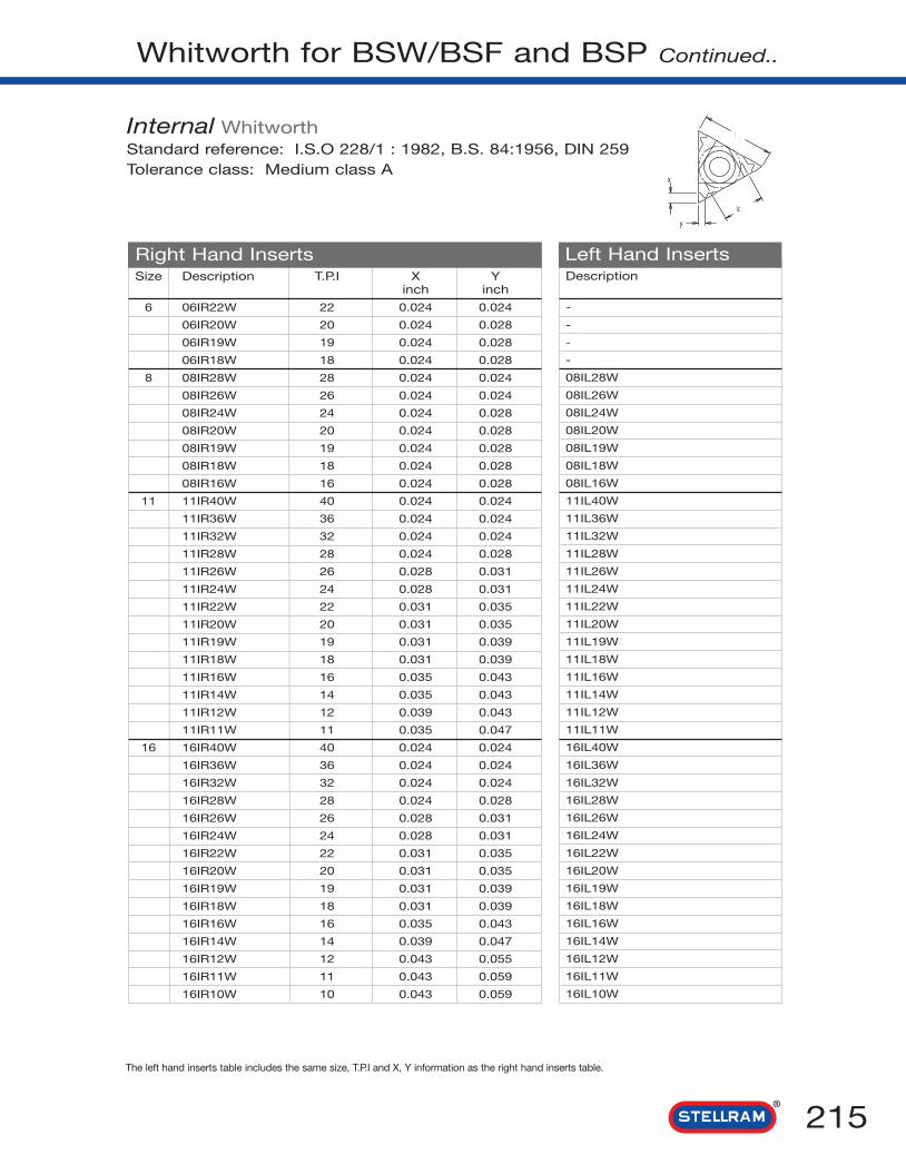
Whitworth for BSW/BSF and BSP Continued..
215
Description
-
-
-
-
08IL28W
08IL26W
08IL24W
08IL20W
08IL19W
08IL18W
08IL16W
11IL40W
11IL36W
11IL32W
11IL28W
11IL26W
11IL24W
11IL22W
11IL20W
11IL19W
11IL18W
11IL16W
11IL14W
11IL12W
11IL11W
16IL40W
16IL36W
16IL32W
16IL28W
16IL26W
16IL24W
16IL22W
16IL20W
16IL19W
16IL18W
16IL16W
16IL14W
16IL12W
16IL11W
16IL10W
Right Hand Inserts Left Hand Inserts
The left hand inserts table includes the same size, T.P.I and X, Y information as the right hand inserts table.
Size Description T.P.I X Yinch inch
6 06IR22W 22 0.024 0.024
06IR20W 20 0.024 0.028
06IR19W 19 0.024 0.028
06IR18W 18 0.024 0.028
8 08IR28W 28 0.024 0.024
08IR26W 26 0.024 0.024
08IR24W 24 0.024 0.028
08IR20W 20 0.024 0.028
08IR19W 19 0.024 0.028
08IR18W 18 0.024 0.028
08IR16W 16 0.024 0.028
11 11IR40W 40 0.024 0.024
11IR36W 36 0.024 0.024
11IR32W 32 0.024 0.024
11IR28W 28 0.024 0.028
11IR26W 26 0.028 0.031
11IR24W 24 0.028 0.031
11IR22W 22 0.031 0.035
11IR20W 20 0.031 0.035
11IR19W 19 0.031 0.039
11IR18W 18 0.031 0.039
11IR16W 16 0.035 0.043
11IR14W 14 0.035 0.043
11IR12W 12 0.039 0.043
11IR11W 11 0.035 0.047
16 16IR40W 40 0.024 0.024
16IR36W 36 0.024 0.024
16IR32W 32 0.024 0.024
16IR28W 28 0.024 0.028
16IR26W 26 0.028 0.031
16IR24W 24 0.028 0.031
16IR22W 22 0.031 0.035
16IR20W 20 0.031 0.035
16IR19W 19 0.031 0.039
16IR18W 18 0.031 0.039
16IR16W 16 0.035 0.043
16IR14W 14 0.039 0.047
16IR12W 12 0.043 0.055
16IR11W 11 0.043 0.059
16IR10W 10 0.043 0.059
Internal WhitworthStandard reference: I.S.O 228/1 : 1982, B.S. 84:1956, DIN 259Tolerance class: Medium class A
ic
l
y
x

Whitworth for BSW/BSF and BSP Continued..
Description
16IL9W
16IL8W
22IL7W
22IL6W
22IL5W
27IL4.5W
27IL4W
Right Hand Inserts Left Hand Inserts
The left hand inserts table includes the same size, T.P.I and X, Y information as the right hand inserts table.
U Style Inserts
216
Size Description T.P.I X Yinch inch
16 16IR9W 9 0.047 0.067
16IR8W 8 0.047 0.059
22 22IR7W 7 0.063 0.091
22IR6W 6 0.063 0.091
22IR5W 5 0.067 0.095
27 27IR4.5W 4.5 0.071 0.102
27IR4W 4 0.078 0.114
Size Description T.P.I X Yinch inch
8 08ILRU14W 14 0.039 0.157
08ILRU12W 12 0.035 0.157
08ILRU11W 11 0.035 0.157
22 22EILRU4.5W 4.5 0.091 0.433
22EILRU4W 4 0.071 0.433
27 27EILRU3.5 3.5 0.083 0.539
27EILRU3.25 3.25 0.078 0.539
27EILRU3 3 0.091 0.539
27EILRU2.75 2.75 0.095 0.539
Multi ToothSize Description T.P.I X Y
inch inch
16 16IR14W2M 14 0.075 0.110
22 22IR14W3M 14 0.114 0.181
22IR11W2M 11 0.091 0.138
ic
l
y
x
ic
l
x
y
l
ic
y
x
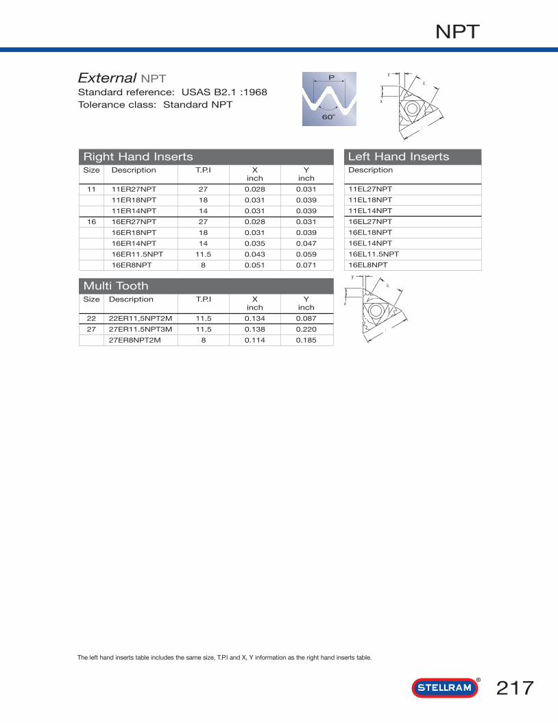
NPT
217
Description
11EL27NPT
11EL18NPT
11EL14NPT
16EL27NPT
16EL18NPT
16EL14NPT
16EL11.5NPT
16EL8NPT
Right Hand Inserts Left Hand Inserts
Multi Tooth
The left hand inserts table includes the same size, T.P.I and X, Y information as the right hand inserts table.
Size Description T.P.I X Yinch inch
11 11ER27NPT 27 0.028 0.031
11ER18NPT 18 0.031 0.039
11ER14NPT 14 0.031 0.039
16 16ER27NPT 27 0.028 0.031
16ER18NPT 18 0.031 0.039
16ER14NPT 14 0.035 0.047
16ER11.5NPT 11.5 0.043 0.059
16ER8NPT 8 0.051 0.071
Size Description T.P.I X Yinch inch
22 22ER11,5NPT2M 11.5 0.134 0.087
27 27ER11.5NPT3M 11.5 0.138 0.220
27ER8NPT2M 8 0.114 0.185
External NPTStandard reference: USAS B2.1 :1968Tolerance class: Standard NPT
P
60˚
x
y
ic
l
x
y
ic
l

NPT Continued..
Description
-
08IL27NPT
08IL18NPT
11IL27NPT
11IL18NPT
11IL14NPT
16IL27NPT
16IL18NPT
16IL14NPT
16IL11.5NPT
16IL8NPT
Right Hand Inserts Left Hand Inserts
The left hand inserts table includes the same size, T.P.I and X, Y information as the right hand inserts table.
218
Size Description T.P.I X inch Y inch
6 06IR27NPT 27 0.024 0.024
8 08IR27NPT 27 0.024 0.024
08IR18NPT 18 0.024 0.024
11 11IR27NPT 27 0.028 0.031
11IR18NPT 18 0.031 0.039
11IR14NPT 14 0.031 0.039
16 16IR27NPT 27 0.028 0.031
16IR18NPT 18 0.031 0.039
16IR14NPT 14 0.035 0.047
16IR11.5NPT 11.5 0.043 0.059
16IR8NPT 8 0.051 0.071
Multi ToothSize Description T.P.I X inch Y inch
22 22IR11,5NPT2M 11.5 0.134 0.087
27 27IR11.5NPT3M 11.5 0.138 0.220
27IR8NPT2M 8 0.114 0.185
Internal NPTStandard reference: USAS B2.1 :1968Tolerance class: Standard NPT
l
ic
y
x
l
ic
y
x

NPTF
219
Description
11EL27NPTF
11EL18NPTF
11EL14NPTF
16EL27NPTF
16EL18NPTF
16EL14NPTF
16EL11.5NPTF
16EL8NPTF
Right Hand Inserts Left Hand Inserts
Multi Tooth
The left hand inserts table includes the same size, T.P.I and X, Y information as the right hand inserts table.
Size Description T.P.I X inch Y inch
11 11ER27NPTF 27 0.028 0.031
11ER18NPTF 18 0.031 0.039
11ER14NPTF 14 0.031 0.039
16 16ER27NPTF 27 0.028 0.031
16ER18NPTF 18 0.031 0.039
16ER14NPTF 14 0.035 0.047
16ER11.5NPTF 11.5 0.043 0.059
16ER8NPTF 8 0.051 0.071
Size Description T.P.I X inch Y inch
22 22ER11,5NPTF2M 11.5 0.134 0.087
27 27ER11.5NPTF3M 11.5 0.138 0.220
27ER8NPTF2M 8 0.114 0.185
External NPTFStandard reference: ANSI B1. 20.3 - 1976Tolerance class: Class 2
P
60˚
x
y
ic
l
x
y
ic
l

NPTF Continued..
Description
-
08IL27NPTF
08IL18NPTF
11IL27NPTF
11IL18NPTF
11IL14NPTF
16IL27NPTF
16IL18NPTF
16IL14NPTF
16IL11.5NPTF
16IL8NPTF
Right Hand Inserts Left Hand Inserts
Multi Tooth
The left hand inserts table includes the same size, T.P.I and X, Y information as the right hand inserts table.
220
Size Description T.P.I X inch Y inch
6 06IR27NPTF 27 0.028 0.024
8 08IR27NPTF 27 0.024 0.024
08IR18NPTF 18 0.024 0.024
11 11IR27NPTF 27 0.028 0.028
11IR18NPTF 18 0.031 0.039
11IR14NPTF 14 0.031 0.039
16 16IR27NPTF 27 0.028 0.028
16IR18NPTF 18 0.031 0.039
16IR14NPTF 14 0.035 0.047
16IR11.5NPTF 11.5 0.043 0.059
16IR8NPTF 8 0.051 0.071
Size Description T.P.I X inch Y inch
22 22IR11,5NPT2M 11.5 0.134 0.087
27 27IR11.5NPT3M 11.5 0.138 0.220
27IR8NPT2M 8 0.114 0.185
Internal NPTFStandard reference: USAS B2.1 :1968Tolerance class: Standard NPT
l
ic
y
x
l
ic
y
x

BSPT
221
Description
16EL28BSPT
16EL19BSPT
16EL14BSPT
16EL11BSPT
Right Hand Inserts Left Hand Inserts
Description
-
08IL28BSPT
08IL19BSPT
11IL28BSPT
11IL19BSPT
11IL14BSPT
16IL28BSPT
16IL19BSPT
16IL14BSPT
16IL11BSPT
The left hand inserts table includes the same size, T.P.I and X, Y information as the right hand inserts table.
Right Hand Inserts Left Hand InsertsSize Description T.P.I X inch Y inch
6 06IR28BSPT 27 0.024 0.024
8 08IR28BSPT 27 0.024 0.024
08IR19BSPT 18 0.024 0.024
11 11IR28BSPT 27 0.028 0.031
11IR19BSPT 18 0.031 0.039
11IR14BSPT 14 0.031 0.039
16 16IR28BSPT 27 0.028 0.031
16IR19BSPT 18 0.031 0.039
16IR14BSPT 14 0.035 0.047
16IR11BSPT 11.5 0.043 0.059
External BSPTStandard reference: B.S. 21:1985Tolerance class: Standard BSPT
Internal BSPTStandard reference: B.S. 21:1985Tolerance class: Standard BSPT
l
ic
y
x
x
y
ic
l
Size Description T.P.I X inch Y inch
16 16ER28BSPT 27 0.028 0.031
16ER19BSPT 18 0.031 0.039
16ER14BSPT 14 0.035 0.047
16ER11BSPT 11.5 0.043 0.059
P
60˚

British Association
Right Hand Inserts
The left hand inserts table includes the same size, T.P.I and X, Y information as the right hand inserts table.
222
Right Hand Inserts
Size Description T.P.I X inch Y inch
11 11ER4BA 38.48 0.031 0.020
16 16ER0BA 25.4 0.031 0.028
16ER2BA 31.35 0.031 0.024
16ER4BA 38.48 0.031 0.020
16ER6BA 47.92 0.031 0.020
16ER8BA 59.67 0.031 0.016
Size Description T.P.I X inch Y inch
11 11IR4BA 38.48 0.031 0.020
16 16IR0BA 25.4 0.031 0.028
16IR2BA 31.35 0.031 0.024
16IR4BA 38.48 0.031 0.020
16IR6BA 47.92 0.031 0.020
16IR8BA 59.67 0.031 0.016
External British AssociationBA form
Internal British AssociationBA form
P
47,5˚
ic
y
x
l
l
x
y
ic

ACME External and Internal
223
Description
11EL16ACME
16EL16ACME
16EL14ACME
16EL12ACME
16EL10ACME
16EL8ACME
22EL8ACME
22EL6ACME
22EL5ACME
27EL4ACME
Right Hand Inserts Left Hand Inserts
U Style Inserts
Description
11IL16ACME
16IL16ACME
16IL14ACME
16IL12ACME
16IL10ACME
16IL8ACME
22IL8ACME
22IL6ACME
22IL5ACME
27IL4ACME
The left hand inserts table includes the same size, T.P.I and X, Y information as the right hand inserts table.
Right Hand Inserts Left Hand Inserts
Size Description T.P.I X inch Y inch
11 11ER16ACME 16 0.035 0.039
16 16ER16ACME 16 0.035 0.039
16ER14ACME 14 0.039 0.047
16ER12ACME 12 0.043 0.047
16ER10ACME 10 0.051 0.051
16ER8ACME 8 0.059 0.059
22 22ER8ACME 8 0.059 0.059
22ER6ACME 6 0.071 0.083
22ER5ACME 5 0.079 0.091
27 27ER4ACME 4 0.091 0.106
Size Description T.P.I X inch Y inch
22 22EILRU4ACME 4 0.091 0.433
27 27EILRU3ACME 3 0.110 0.539
Size Description T.P.I X inch Y inch
11 11IR16ACME 16 0.035 0.039
16 16IR16ACME 16 0.035 0.039
16IR14ACME 14 0.039 0.047
16IR12ACME 12 0.043 0.047
16IR10ACME 10 0.051 0.051
16IR8ACME 8 0.059 0.059
22 22IR8ACME 8 0.059 0.059
22IR6ACME 6 0.071 0.083
22IR5ACME 5 0.079 0.091
27 27IR4ACME 4 0.091 0.106
External ACME FormStandard reference: ANSI B1.5: 1988Tolerance class: 3G
Internal ACME FormStandard reference: ANSI B1.5: 1988Tolerance class: 3G
ic
y
x
l
y
x
l
ic
l
x
y
ic
P
29˚

STACME External and Internal
Description
11EL16STACME
16EL16STACME
16EL14STACME
16EL12STACME
16EL10STACME
16EL8STACME
16EL6STACME
22EL5STACME
22EL4STACME
27EL4STACME
27EL3STACME
Right Hand Inserts Left Hand Inserts
U Style Inserts
Description
11IL16STACME
16IL16STACME
16IL14STACME
16IL12STACME
16IL10STACME
16IL8STACME
16IL6STACME
22IL5STACME
22IL4STACME
27IL4STACME
27IL3STACME
The left hand inserts table includes the same size, T.P.I and X, Y information as the right hand inserts table.
Right Hand Inserts Left Hand Inserts
224
Size Description T.P.I X inch Y inch
11 11ER16STACME 16 0.039 0.039
16 16ER16STACME 16 0.039 0.039
16ER14STACME 14 0.043 0.043
16ER12STACME 12 0.047 0.047
16ER10STACME 10 0.051 0.051
16ER8STACME 8 0.059 0.059
16ER6STACME 6 0.071 0.071
22 22ER5STACME 5 0.078 0.091
22ER4STACME 4 0.091 0.095
27 27ER4STACME 4 0.091 0.095
27ER3STACME 3 0.110 0.114
Size Description T.P.I X inch Y inch
22 22EILRU4STACME 4 0.098 0.433
27 27EILRU3STACME 3 0.130 0.539
Size Description T.P.I X inch Y inch
11 11IR16STACME 16 0.039 0.039
16 16IR16STACME 16 0.039 0.039
16IR14STACME 14 0.043 0.043
16IR12STACME 12 0.047 0.047
16IR10STACME 10 0.051 0.051
16IR8STACME 8 0.059 0.059
16IR6STACME 6 0.071 0.071
22 22IR5STACME 5 0.078 0.091
22IR4STACME 4 0.091 0.095
27 27IR4STACME 4 0.091 0.095
27IR3STACME 3 0.110 0.114
External STUB ACMEStandard reference: ANSI B1.8: 1988Tolerance class: 2G
Internal STUB ACMEStandard reference: ANSI B1.8: 1988Tolerance class: 2G
P
29˚
ic
y
x
l
y
x
l
ic
l
x
y
ic

Trapezoidal External and Internal
225
Description
16EL1.5TR
16EL2.0TR
16EL3.0TR
22EL4.0TR
22EL5.0TR
22EL6.0TR
27EL6.0TR
Right Hand Inserts Left Hand Inserts
U Style Inserts
The left hand inserts table includes the same size, pitch and X, Y information as the right hand inserts table.
Size Description Pitch X inch Y inch
16 16ER1.5TR 1.5 0.039 0.043
16ER2.0TR 2.0 0.039 0.051
16ER3.0TR 3.0 0.051 0.059
22 22ER4.0TR 4.0 0.071 0.075
22ER5.0TR 5.0 0.078 0.095
22ER6.0TR 6.0 0.091 0.106
27 27ER6.0TR 6.0 0.091 0.106
Size Description Pitch X inch Y inch
22 22EILRU6.0TR 6.0 0.078 0.433
22EILRU8.0TR 7.0 0.091 0.433
27 27EILRU8.0TR 8.0 0.098 0.539
27EILRU9.0TR 9.0 0.118 0.539
Description
16IL1.5TR
16IL2.0TR
16IL3.0TR
22IL4.0TR
22IL5.0TR
22IL6.0TR
27IL6.0TR
Right Hand Inserts Left Hand InsertsSize Description Pitch X inch Y inch
16 16IR1.5TR 1.5 0.039 0.043
16IR2.0TR 2.0 0.039 0.051
16IR3.0TR 3.0 0.051 0.059
22 22IR4.0TR 4.0 0.071 0.075
22IR5.0TR 5.0 0.078 0.095
22IR6.0TR 6.0 0.091 0.106
27 27IR6.0TR 6.0 0.091 0.106
External TrapezoidalStandard reference: DIN 103Tolerance class: 7e / 7H
Internal TrapezoidalStandard reference: DIN 103Tolerance class: 7e / 7H
P
30˚
x
y
ic
l
l
ic
y
x
ic
l
x
y
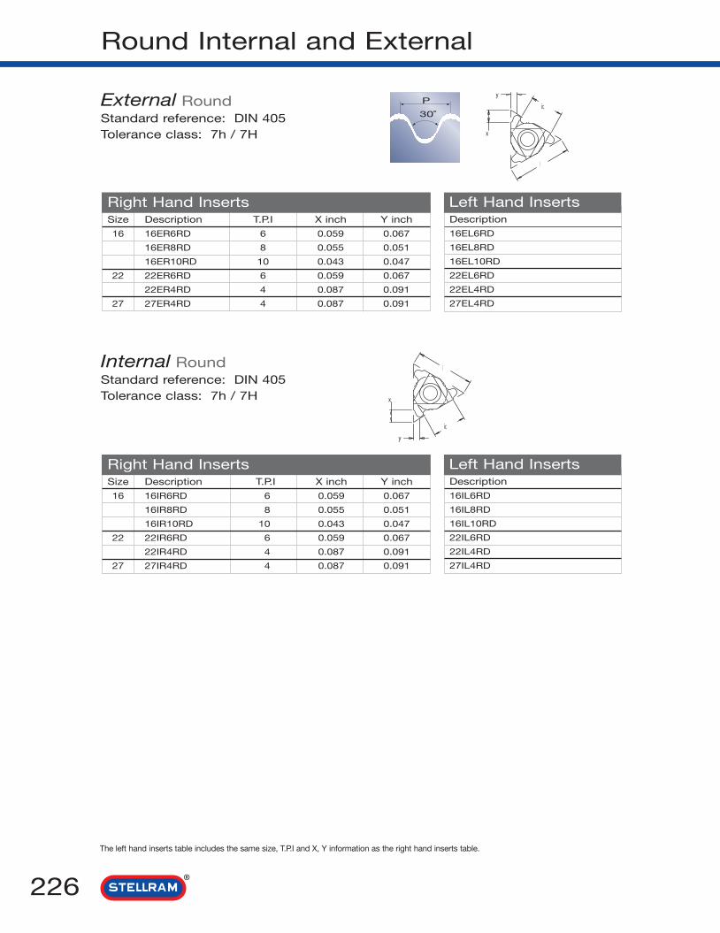
Round Internal and External
Description
16EL6RD
16EL8RD
16EL10RD
22EL6RD
22EL4RD
27EL4RD
Right Hand Inserts Left Hand Inserts
The left hand inserts table includes the same size, T.P.I and X, Y information as the right hand inserts table.
226
Size Description T.P.I X inch Y inch
16 16ER6RD 6 0.059 0.067
16ER8RD 8 0.055 0.051
16ER10RD 10 0.043 0.047
22 22ER6RD 6 0.059 0.067
22ER4RD 4 0.087 0.091
27 27ER4RD 4 0.087 0.091
Description
16IL6RD
16IL8RD
16IL10RD
22IL6RD
22IL4RD
27IL4RD
Right Hand Inserts Left Hand InsertsSize Description T.P.I X inch Y inch
16 16IR6RD 6 0.059 0.067
16IR8RD 8 0.055 0.051
16IR10RD 10 0.043 0.047
22 22IR6RD 6 0.059 0.067
22IR4RD 4 0.087 0.091
27 27IR4RD 4 0.087 0.091
External RoundStandard reference: DIN 405Tolerance class: 7h / 7H
Internal RoundStandard reference: DIN 405Tolerance class: 7h / 7H
P
30˚
y
x
ic
l
l
ic
x
y

PG
227
Description
16EL20PG
16EL18PG
16EL16PG
Left Hand Inserts
The left hand inserts table includes the same size, T.P.I and X, Y information as the right hand inserts table.
Size Description T.P.I X Y Nominalinch inch Thread
16 16ER20PG 20 0.028 0.031 Pg 7
16ER18PG 18 0.031 0.035 Pg 9 / 11 / 13.5 / 16
16ER16PG 16 0.031 0.039 Pg21 / 29 / 36 / 42 / 48
Right Hand Inserts
Description
08IL20PG
11IL20PG
11IL18PG
11IL16PG
16IL20PG
16IL18PG
16IL16PG
Left Hand InsertsRight Hand InsertsSize Description T.P.I X Y Nominal
inch inch Thread
8 08IR20PG 20 0.024 0.028 Pg 7
11 11IR20PG 20 0.028 0.031 Pg 7
11IR18PG 18 0.031 0.035 Pg 9 / 11 / 13.5 / 16
11IR16PG 16 0.031 0.039 Pg21 / 29 / 36 / 42 / 48
16 16IR20PG 20 0.028 0.031 Pg 7
16IR18PG 18 0.031 0.035 Pg 9 / 11 / 13.5 / 16
16IR16PG 16 0.031 0.039 Pg21 / 29 / 36 / 42 / 48
External PG (Panzer Gewinde)Standard reference: DIN 40430Tolerance class: Standard
Internal PGStandard reference: DIN 40430Tolerance class: Standard
x
y
ic
l
l
ic
y
x
P
80˚

UNJ
Description
11EL48UNJ
11EL44UNJ
11EL40UNJ
11EL36UNJ
11EL32UNJ
11EL28UNJ
11EL24UNJ
11EL20UNJ
11EL18UNJ
11EL16UNJ
11EL14UNJ
16EL48UNJ
16EL44UNJ
16EL40UNJ
16EL36UNJ
16EL32UNJ
16EL28UNJ
16EL24UNJ
16EL20UNJ
16EL18UNJ
16EL16UNJ
16EL14UNJ
16EL13UNJ
16EL12UNJ
16EL11UNJ
16EL10UNJ
16EL9UNJ
16EL8UNJ
Right Hand Inserts Left Hand Inserts
The left hand inserts table includes the same size, T.P.I and X, Y information as the right hand inserts table.
228
Size Description T.P.I X Yinch inch
11 11ER48UNJ 48 0.024 0.024
11ER44UNJ 44 0.024 0.024
11ER40UNJ 40 0.024 0.024
11ER36UNJ 36 0.024 0.024
11ER32UNJ 32 0.024 0.024
11ER28UNJ 28 0.024 0.024
11ER24UNJ 24 0.028 0.031
11ER20UNJ 20 0.031 0.035
11ER18UNJ 18 0.031 0.039
11ER16UNJ 16 0.031 0.039
11ER14UNJ 14 0.035 0.039
16 16ER48UNJ 48 0.024 0.024
16ER44UNJ 44 0.024 0.024
16ER40UNJ 40 0.024 0.024
16ER36UNJ 36 0.024 0.024
16ER32UNJ 32 0.024 0.024
16ER28UNJ 28 0.024 0.024
16ER24UNJ 24 0.028 0.031
16ER20UNJ 20 0.031 0.035
16ER18UNJ 18 0.031 0.039
16ER16UNJ 16 0.031 0.039
16ER14UNJ 14 0.039 0.047
16ER13UNJ 13 0.039 0.051
16ER12UNJ 12 0.043 0.055
16ER11UNJ 11 0.043 0.059
16ER10UNJ 10 0.043 0.059
16ER9UNJ 9 0.047 0.063
16ER8UNJ 8 0.047 0.063
External UNJStandard reference: MIL - S 8879CTolerance class: 3A / 3B
P
60˚
x
y
l
ic

MJ
229
Description
16EL1.0MJ
16EL1.25MJ
16EL1.5MJ
16EL2.0MJ
16EL2.5MJ
16EL3.0MJ
Right Hand Inserts Left Hand Inserts
The left hand inserts table includes the same size, pitch and X, Y information as the right hand inserts table.
Size Description Pitch X Yinch inch
16 16ER1.0MJ 1 0.024 0.028
16ER1.25MJ 1.25 0.028 0.035
16ER1.5MJ 1.5 0.031 0.039
16ER2.0MJ 2 0.039 0.051
16ER2.5MJ 2.5 0.043 0.059
16ER3.0MJ 3 0.047 0.063
External MJStandard reference: ISO 5855Tolerance class: 4h / 6h - 4H / 5H
P
60˚
x
y
l
ic

Description
16EL20BBUTT
16EL16BBUTT
16EL12BBUTT
16EL10BBUTT
22EL8BBUTT
22EL6BBUTT
27EL4BBUTT
Right Hand Inserts Left Hand Inserts
British Buttress
The left hand inserts table includes the same size, pitch and X, Y information as the right hand inserts table.
230
Size Description T.P.I X inch Y inch
16 16ER20BBUTT 20 0.039 0.055
16ER16BBUTT 16 0.051 0.075
16ER12BBUTT 12 0.055 0.078
16ER10BBUTT 10 0.059 0.091
22 22ER8BBUTT 8 0.078 0.126
22ER6BBUTT 6 0.087 0.138
27 27ER4BBUTT 4 0.087 0.138
Description
16IL20BBUTT
16IL16BBUTT
16IL12BBUTT
16IL10BBUTT
22IL8BBUTT
22IL6BBUTT
27IL4BBUTT
Right Hand Inserts Left Hand InsertsSize Description T.P.I X inch Y inch
16 16IR20BBUTT 20 0.039 0.055
16IR16BBUTT 16 0.051 0.075
16IR12BBUTT 12 0.055 0.078
16IR10BBUTT 10 0.059 0.091
22 22IR8BBUTT 8 0.078 0.126
22IR6BBUTT 6 0.087 0.138
27 27IR4BBUTT 4 0.087 0.138
External British ButtressTolerance class: Medium Class
Internal British ButtressTolerance class: Medium Class
P
45˚7˚
l
ic
y
x
x
y
ic
l
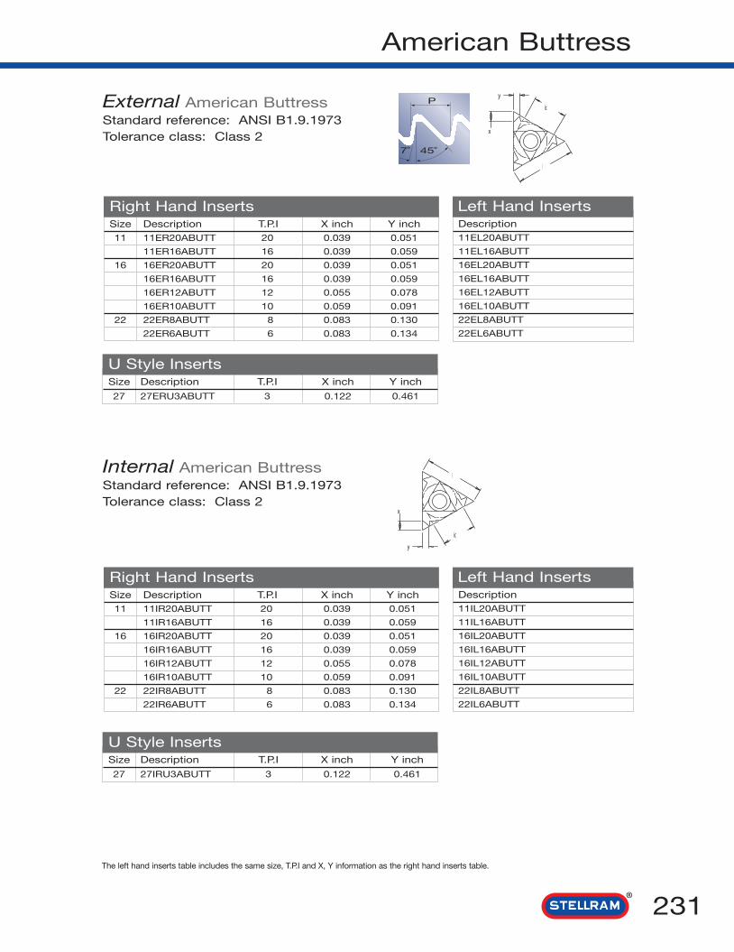
American Buttress
231
The left hand inserts table includes the same size, T.P.I and X, Y information as the right hand inserts table.
Description11EL20ABUTT
11EL16ABUTT
16EL20ABUTT
16EL16ABUTT
16EL12ABUTT
16EL10ABUTT
22EL8ABUTT
22EL6ABUTT
Right Hand Inserts Left Hand Inserts
U Style Inserts
Size Description T.P.I X inch Y inch11 11ER20ABUTT 20 0.039 0.051
11ER16ABUTT 16 0.039 0.059
16 16ER20ABUTT 20 0.039 0.051
16ER16ABUTT 16 0.039 0.059
16ER12ABUTT 12 0.055 0.078
16ER10ABUTT 10 0.059 0.091
22 22ER8ABUTT 8 0.083 0.130
22ER6ABUTT 6 0.083 0.134
Description11IL20ABUTT
11IL16ABUTT
16IL20ABUTT
16IL16ABUTT
16IL12ABUTT
16IL10ABUTT
22IL8ABUTT
22IL6ABUTT
Right Hand Inserts Left Hand Inserts
U Style InsertsSize Description T.P.I X inch Y inch
27 27IRU3ABUTT 3 0.122 0.461
Size Description T.P.I X inch Y inch11 11IR20ABUTT 20 0.039 0.051
11IR16ABUTT 16 0.039 0.059
16 16IR20ABUTT 20 0.039 0.051
16IR16ABUTT 16 0.039 0.059
16IR12ABUTT 12 0.055 0.078
16IR10ABUTT 10 0.059 0.091
22 22IR8ABUTT 8 0.083 0.130
22IR6ABUTT 6 0.083 0.134
Size Description T.P.I X inch Y inch
27 27ERU3ABUTT 3 0.122 0.461
External American ButtressStandard reference: ANSI B1.9.1973Tolerance class: Class 2
Internal American ButtressStandard reference: ANSI B1.9.1973Tolerance class: Class 2
P
45˚7˚
x
y
ic
l
l
ic
y
x

Description
22EL4API382
22EL4API383
22EL5API403
22EL4API502
22EL4API503
22EL6API551.5
27EL4API380.5
27EL4API382
27EL4API383
27EL4API502
27EL4API503
27EL4API652
Left Hand Inserts
API (Oilfield)
The left hand inserts table includes the same size, T.P.I and X, Y information as the right hand inserts table.
232
Size Description T.P.I Taper Taper X Yangle I.P.F inch inch
22 22ER4API382 4 4.43º 2 0.083 0.110
22ER4API383 4 7.10º 3 0.083 0.110
22ER5API403 5 7.10º 3 0.071 0.098
22ER4API502 4 7.10º 3 0.078 0.118
22ER4API503 4 7.10º 3 0.078 0.118
22ER6API551.5 6 3.33º 1.5 0.071 0.102
27 27ER4API380.5 4 1.11º 0.5 0.083 0.110
27ER4API382 4 4.43º 2 0.083 0.110
27ER4API383 4 7.10º 3 0.083 0.110
27ER4API502 4 4.43º 2 0.078 0.118
27ER4API503 4 7.10º 3 0.078 0.078
27ER4API652 4 4.43º 2 0.083 0.122
Description
22IL4API382
22IL4API383
22IL5API403
22IL4API502
22IL4API503
22IL6API551.5
27IL4API380.5
27IL4API382
27IL4API383
27IL4API502
27IL4API503
27IL4API652
Left Hand InsertsSize Description T.P.I Taper Taper X Y
angle I.P.F inch inch
22 22IR4API382 4 4.43º 2 0.083 0.110
22IR4API383 4 7.10º 3 0.083 0.110
22IR5API403 5 7.10º 3 0.071 0.098
22IR4API502 4 4.43º 2 0.078 0.118
22IR4API503 4 7.10º 3 0.078 0.118
22IR6API551.5 6 3.33º 1.5 0.071 0.102
27 27IR4API380.5 4 1.11º 0.5 0.083 0.110
27IR4API382 4 4.43º 2 0.083 0.110
27IR4API383 4 7.10º 3 0.083 0.110
27IR4API502 4 4.43º 2 0.078 0.118
27IR4API503 4 7.10º 3 0.078 0.078
27IR4API652 4 4.43º 2 0.083 0.122
External APIStandard reference: APIspecification 7:1990Tolerance class: Standard API
Internal APIStandard reference: APIspecification 7:1990Tolerance class: Standard API
P
60˚
l
ic
y
x
x
y
ic
l
Right Hand Inserts
Right Hand Inserts

API Round (Oilfield)
233
The left hand inserts table includes the same size, T.P.I range, I.P.F and X, Y information as the right hand inserts table.
Description
16EL10APIRD
16EL8APIRD
22EL8APIRD
Right Hand Inserts Left Hand InsertsSize Description T.P.I X inch Y inch
16 16ER10APIRD 10 0.047 0.055
16ER8APIRD 8 0.051 0.059
22 22ER8APIRD 8 0.051 0.059
Description
16IL10APIRD
16IL8APIRD
22IL8APIRD
Right Hand Inserts Left Hand InsertsSize Description T.P.I X inch Y inch
16 16IR10APIRD 10 0.047 0.055
16IR8APIRD 8 0.051 0.059
22 22IR8APIRD 8 0.051 0.059
External API RoundStandard reference: API Standard 5B: 1979
Tolerance class: Standard API round
Internal API RoundStandard reference: API Standard 5B:1979Tolerance class: Standard API round
P
60˚
x
y
ic
l
l
ic
y
x
Oilfield ConnectorsReference to T.P.I Taper CONNECTOR No. or Size
Part Number I.P.F
API V 0.038R 4 2 NC23, NC28, NC31, NC35, NC38, NC40, NC44, NC46
NC50, 4FH, 2-3 /8IF, 3-1/2IF,4IF, 4-1/2IF, 5-1/2IF
API V 0.038R 4 3 NC56, NC61, NC70, NC77
API V 0.040 5 3 2-3/8REG, 2-7/8 REG, 3-1/2REG, 4-1/2 REG,
3-1/2FH, 4-1/2 FH
API V 0.050 4 3 5-1/2 REG, 7-5/8 REG, 8-5/8 REG
API V 0.050 4 2 6-5/8 REG, 5-1/2 FH, 6-5/8 FH
API V 0.055 6 1.5 NC10, NC12, NC13, NC16
API V 0.065 4 2 Superceded by API V 0.038R
Extreme Line Casing 6 1.5 5 to 7-5/8
Extreme Line Casing 5 1.25 8-5/8 to 10-3/4
Buttress Casing 5 0.75 4-1/2 to 13-3/8
Buttress Casing 5 1 16 to 20
Note: Non stocked items, made to order only

PAC (Oilfield)
The left hand inserts table includes the same size, T.P.I and X, Y information as the right hand inserts table.
234
Description
22EL4PAC
Left Hand InsertsSize Description T.P.I X inch Y inch
22 22EL4PAC 4 0.083 0.122
Description
22IL4PAC
Right Hand Inserts Left Hand InsertsSize Description T.P.I X inch Y inch
22 22IR4PAC 4 0.083 0.122
Right Hand Inserts
External PAC
Internal PAC
P
60˚
l
ic
y
x
x
y
ic
l
Note: Non stocked items, made to order only

Extreme Line Casing (Oilfield)
235
The left hand inserts table includes the same size, T.P.I range, I.P.F and X, Y information as the right hand inserts table.
Description
22EL6ELC1.5
22EL5ELC1.25
Right Hand Inserts Left Hand InsertsSize Description T.P.I Taper X Y
I.P.F inch inch
22 22ER6ELC1.5 6 1.5 0.075 0.075
22ER5ELC1.25 5 1.25 0.095 0.091
Description
22IL6ELC1.5
22IL5ELC1.25
Right Hand Inserts Left Hand InsertsSize Description T.P.I Taper X Y
I.P.F inch inch
22 22IR6ELC1.5 6 1.5 0.075 0.075
22IR5ELC1.25 5 1.25 0.095 0.091
External Extreme Line CasingStandard reference: API Standard 5B: 979Tolerance class: Standard API round
Internal Extreme Line CasingStandard reference: API Standard 5B:1979Tolerance class: Standard API round
P
12˚
l
ic
y
x
x
y
ic
l
Note: Non stocked items, made to order only

API Buttress Casing (Oilfield)
The left hand inserts table includes the same size, T.P.I and X, Y information as the right hand inserts table.
236
Description
22EL5BUTT0.75
22EL5BUTT1.0
22EL5BUTT1.25
Right Hand Inserts Left Hand InsertsSize Description T.P.I Taper X Y
I.P.F inch inch
22 22ER5BUTT0.75 5 0.75 0.087 0.095
22ER5BUTT1.0 5 1 0.091 0.095
22ER5BUTT1.25 5 1.25 0.095 0.095
Description
22IL5BUTT0.75
22IL5BUTT1.0
22IL5BUTT1.25
Left Hand InsertsRight Hand InsertsSize Description T.P.I Taper X Y
I.P.F inch inch
22 22IR5BUTT0.75 5 0.75 0.087 0.095
22IR5BUTT1.0 5 1 0.091 0.095
22IR5BUTT1.25 5 1.25 0.095 0.095
External API Buttress CasingStandard reference: API Specification 7.1990Tolerance class: Standard API
Internal API Buttress CasingStandard reference: API Specification 7.1990Tolerance class: Standard API
B(NR)
3˚
B(ER)
10˚
x
y
ic
l
l
ic
y
x
Note: Non stocked items, made to order only
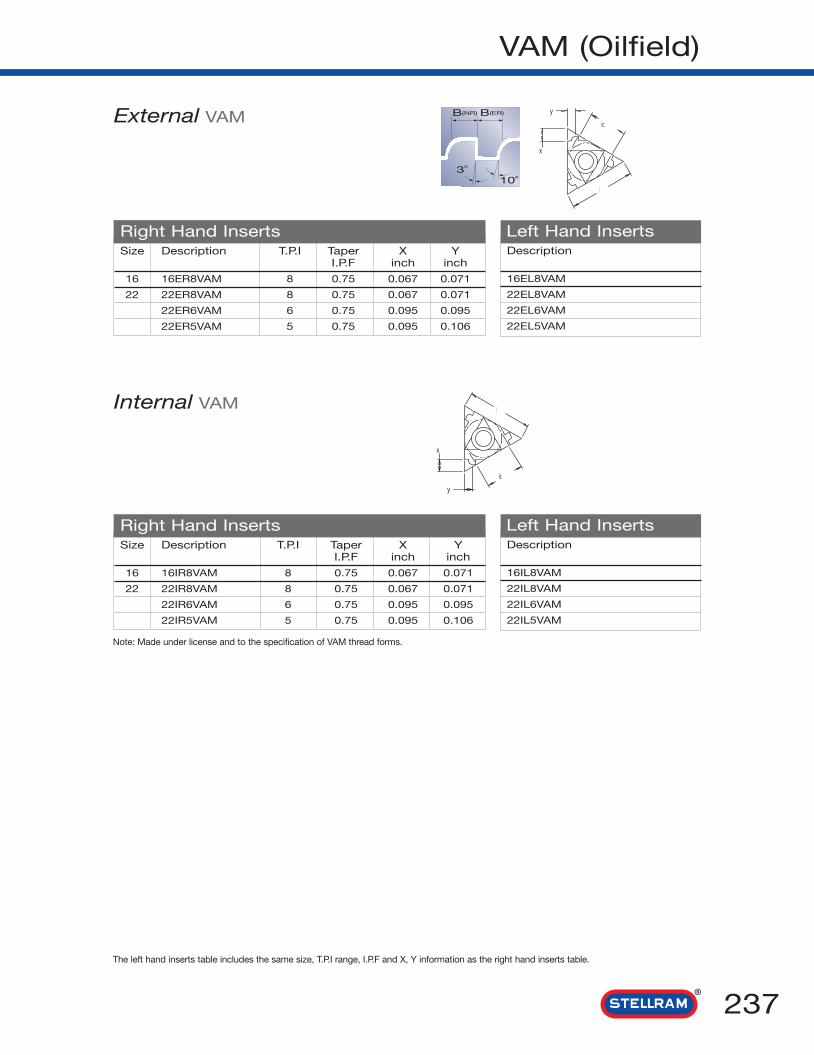
VAM (Oilfield)
237
The left hand inserts table includes the same size, T.P.I range, I.P.F and X, Y information as the right hand inserts table.
Description
16EL8VAM
22EL8VAM
22EL6VAM
22EL5VAM
Right Hand Inserts Left Hand InsertsSize Description T.P.I Taper X Y
I.P.F inch inch
16 16ER8VAM 8 0.75 0.067 0.071
22 22ER8VAM 8 0.75 0.067 0.071
22ER6VAM 6 0.75 0.095 0.095
22ER5VAM 5 0.75 0.095 0.106
Description
16IL8VAM
22IL8VAM
22IL6VAM
22IL5VAM
Right Hand Inserts Left Hand InsertsSize Description T.P.I Taper X Y
I.P.F inch inch
16 16IR8VAM 8 0.75 0.067 0.071
22 22IR8VAM 8 0.75 0.067 0.071
22IR6VAM 6 0.75 0.095 0.095
22IR5VAM 5 0.75 0.095 0.106
External VAM
Internal VAM
B(NR)
3˚
B(ER)
10˚
x
y
ic
l
l
ic
y
x
Note: Made under license and to the specification of VAM thread forms.

238
Threading Toolholder Designation
Min. Bore
1 Utilisation
E R 07 K501 2 3 4 5
166
External Internal
E I
2 Hand
Left Hand Right Hand
L R
3 Shank Size or Tool Diameter
External Square Shank
e.g. 0.75" x 0.75"
4 Minimum Bore Size
Internal Round Shank Ø
e.g. 0750095 = d Ø 0.75"D1 Ø 0.95"
d
D1
5 Tool Length inch
D = 2.5
F = 3.25
H = 4
K = 5
L = 5.5
M = 6
P = 7
R = 8
S = 10
T = 12
U = 14
V = 16
L
6 Insert SizeL IC
mm Inch
06 5/3208 3/1608U 3/1611 1/416 3/822 1/222U 1/2U27 5/827U 5/8U
IC
L
Neutral
U
7 Option
-7

239
External Threading Toolholders
ER
Description Dimensions (inch) Insertsb l1 l2 f h h1
ER/LN037516 0.375 6.00 0.750 0.375 0.375 0.375 16ER
ER/L050016 0.500 6.00 0.875 0.500 0.500 0.500 16E_
ER/L062516 0.625 6.00 0.875 0.625 0.625 0.625 16E_
ER/L0750K16 0.750 5.00 1.060 1.000 0.750 0.750 16E_
ER/L1000M16 1.000 6.00 1.060 1.250 1.000 1.000 16E_
ER/L1250Q16 1.250 7.00 1.180 1.570 1.250 1.250 16E_
ER/L1000M22 1.000 6.00 1.180 1.250 1.000 1.000 22E_
ER/L1250Q22 1.250 7.00 1.180 1.570 1.250 1.250 22ER
ER1500R22 1.500 8.00 - 2.000 1.500 1.500 22E_
ER1250Q22U 1.250 7.00 - 0.830 1.250 1.250 22E_
ER1500R22U 1.500 8.00 1.380 1.140 1.500 1.500 22E_
ER/L1250Q27 1.250 7.00 1.380 1.570 1.250 1.250 27E_
ER/1500R27 1.500 8.00 1.380 2.000 1.500 1.500 27E_
ER/L1500R27U 1.500 8.00 - 1.040 1.500 1.500 27E_
ER
Part Number Insert Key Anvil AnvilScrew Screw
E_N037516 to E_1250Q16 SA3T T10F YE3/YI3 SY3T
E_1000M22 to E_1500R22U SA4T T20F YE4/YI4 SY4T
E_1250Q27 to E_1500R27U SA5T T25F YE5/YI5 SY5T
SPARES
Ordering Example: ER1000M16
For RIGHT HAND toolholders and inserts, specify R = E_RFor LEFT HAND toolholders and inserts, specify L = E_L

Internal Threading Toolholders
IR
240
Description Dimensions (inch) Min. Minor Insertsd d1 l1 l2 f Thread ø
IRN0500024H06 0.50 0.23 4.0 0.51 0.17 0.24 06IR
IR/LN0625031K08 0.625 0.25 5.0 0.67 0.20 0.31 08I_
IR/LN0625035K08U 0.625 0.32 5.0 0.83 0.25 0.35 08I_
IR/LN0625039K08 0.625 0.31 5.0 0.67 0.24 0.39 08IR
IR/LN0375051K11 0.375 0.37 5.0 1.00 0.29 0.51 11I_
IR/LN0625063M11 0.625 0.49 6.0 1.57 0.35 0.63 11IR
IR/LN0750051M11 0.75 0.39 6.0 1.00 0.29 0.51 11I_
IR/LN0625071M16 0.625 0.47 6.0 1.57 0.37 0.71 16I_
IR/LN0750083Q16 0.75 0.62 7.0 1.57 0.49 0.83 16I_
IR/L0750095Q16 0.75 0.73 7.0 2.00 0.51 0.95 16I_
IR/L1000114R16 1.00 0.94 8.0 2.36 0.63 1.14 16I_
IR/L1250142S16 1.25 1.24 10.0 2.36 0.77 1.42 16I_
IR/L1500173T16 1.50 1.57 12.0 - 0.94 1.73 16I_
IR/LN0750106Q22 0.75 0.75 7.0 - 0.61 1.06 22I_
IR/L1000126R22 1.00 0.96 8.0 - 0.70 1.26 22IR
IR1250153S22 1.25 1.25 10.0 - 0.77 1.53 22I_
IR1500185T22 1.50 1.57 12.0 - 1.02 1.85 22IR
IR1250165S22U 1.25 1.25 10.0 - 1.00 1.65 22I_
IR/L1250157S27 1.25 1.25 10.0 - 0.88 1.57 27IR
IR/L1500189T27 1.50 1.57 12.0 - 1.04 1.89 27IR
IR1250165S27U 1.25 1.39 10.0 - 0.97 1.65 27I_
Ordering Example: IRN0625031K08
All tools with through coolant hole
IR
For RIGHT HAND toolholders and inserts, specify R = IRFor LEFT HAND toolholders and inserts, specify L = IL
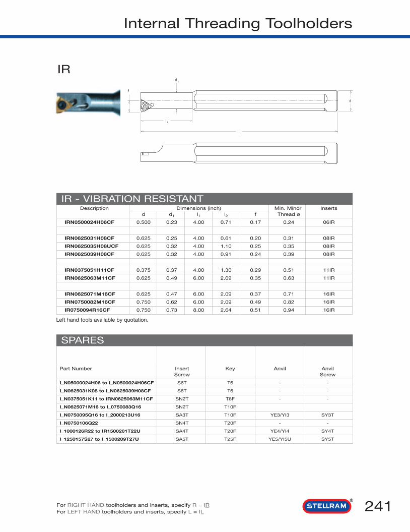
241
Internal Threading Toolholders
IR
Description Dimensions (inch) Min. Minor Insertsd d1 l1 l2 f Thread ø
IRN0500024H06CF 0.500 0.23 4.00 0.71 0.17 0.24 06IR
IRN0625031H08CF 0.625 0.25 4.00 0.61 0.20 0.31 08IR
IRN0625035H08UCF 0.625 0.32 4.00 1.10 0.25 0.35 08IR
IRN0625039H08CF 0.625 0.32 4.00 0.91 0.24 0.39 08IR
IRN0375051H11CF 0.375 0.37 4.00 1.30 0.29 0.51 11IR
IRN0625063M11CF 0.625 0.49 6.00 2.09 0.35 0.63 11IR
IRN0625071M16CF 0.625 0.47 6.00 2.09 0.37 0.71 16IR
IRN0750082M16CF 0.750 0.62 6.00 2.09 0.49 0.82 16IR
IR0750094R16CF 0.750 0.73 8.00 2.64 0.51 0.94 16IR
IR - VIBRATION RESISTANT
Part Number Insert Key Anvil AnvilScrew Screw
I_N05000024H06 to I_N0500024H06CF S6T T6 - -
I_N0625031K08 to I_N0625039H08CF S8T T6 - -
I_N0375051K11 to IRN0625063M11CF SN2T T8F - -
I_N0625071M16 to I_0750083Q16 SN2T T10F
I_N0750095Q16 to I_2000213U16 SA3T T10F YE3/YI3 SY3T
I_N0750106Q22 SN4T T20F - -
I_1000126R22 to IR1500201T22U SA4T T20F YE4/YI4 SY4T
I_1250157S27 to I_1500209T27U SA5T T25F YE5/YI5U SY5T
SPARES
For RIGHT HAND toolholders and inserts, specify R = IRFor LEFT HAND toolholders and inserts, specify L = IL
Left hand tools available by quotation.

242
In-Feed & Recommendations
MODIFIED FLANK IN-FEED
RADIAL IN-FEED
ALTERNATING FLANK IN-FEED
Radial In-Feed
• Most commonly used method on manual lathes.
• Equal wear on leading and trailing edge.
• Good surface finish on trailing edge.
• Use on work hardening materials.
• Use on short chipping materials.
• For pitches of less than 1,5mm or 16 T.P.I.
Modified Flank In-Feed
• For threads greater than 1,5mm or 16 T.P.I.
• Reduced cutting pressure on larger pitches.
• Reduced chatter.
• Directs chip away from the cutting edge.
• Displaced in-feed angle improves surface finish.
• First choice for internal threading.
Alternating Flank In-Feed
• Recommended for large pitches, square ACMEand trapezoidal forms.
• Recommended for long chipping materials.
• Method divides the work between both flanks.
• Results in equal wear.
• Less cutting pressure.
• Not available on all lathes.

243
In-Feed Recommendations
ThreadingThe table below provides recommendations for depths of cut for thedifferent passes. These recommendations are intended as starting valuesfor machining in steel and include stock 0.001" - 0.003" above crest. Thesuitable number of passes must be determined by trial and error.
Pitch (mm)
No. of 0,5 0,75 0,8 1,0 1,25 1,5 1,75 2,0 2,5 3,0 3,5 4,0 4,5 5,0 5,5 6,0
Passes Radial infeed per pass (inch)
1 0.004 0.007 0.007 0.007 0.007 0.009 0.009 0.010 0.011 0.011 0.013 0.013 0.015 0.016 0.017 0.018
2 0.004 0.006 0.006 0.007 0.007 0.008 0.008 0.009 0.010 0.010 0.012 0.013 0.013 0.015 0.016 0.017
3 0.003 0.004 0.005 0.005 0.006 0.007 0.006 0.007 0.008 0.008 0.010 0.010 0.011 0.013 0.013 0.014
4 0.003 0.003 0.003 0.004 0.005 0.006 0.006 0.006 0.007 0.007 0.008 0.009 0.009 0.011 0.011 0.012
5 0.014 0.020 0.021 0.003 0.004 0.005 0.005 0.006 0.006 0.006 0.007 0.007 0.009 0.009 0.009 0.011
6 0.026 0.003 0.003 0.004 0.005 0.005 0.006 0.007 0.007 0.008 0.009 0.009 0.009
7 0.032 0.038 0.004 0.004 0.005 0.005 0.006 0.006 0.007 0.008 0.008 0.009
8 0.003 0.003 0.004 0.005 0.006 0.006 0.007 0.007 0.007 0.008
9 0.045 0.050 0.004 0.005 0.006 0.006 0.006 0.007 0.007 0.008
10 0.003 0.004 0.005 0.005 0.006 0.007 0.007 0.007
11 0.063 0.004 0.004 0.005 0.006 0.006 0.006 0.007
12 0.003 0.003 0.005 0.005 0.006 0.006 0.006
13 0.074 0.087 0.004 0.005 0.005 0.005 0.006
14 0.003 0.004 0.004 0.005 0.006
15 0.099 0.111 0.123 0.005 0.005
16 0.004 0.004
0.135 0.147
I.S.O Metric (ISO) 60°, External
Pitch (mm)
No. of 0,5 0,75 1,0 1,25 1,5 1,75 2,0 2,5 3,0 3,5 4,0 4,5 5,0 5,5 6,0
Passes Radial infeed per pass (inch)
1 0.004 0.007 0.007 0.008 0.010 0.009 0.010 0.011 0.011 0.012 0.013 0.014 0.015 0.015 0.016
2 0.004 0.005 0.006 0.007 0.008 0.008 0.009 0.009 0.009 0.011 0.012 0.013 0.014 0.014 0.016
3 0.003 0.004 0.004 0.005 0.006 0.006 0.007 0.007 0.008 0.009 0.009 0.011 0.012 0.012 0.014
4 0.003 0.003 0.004 0.004 0.004 0.005 0.006 0.006 0.006 0.008 0.008 0.009 0.010 0.010 0.011
5 0.014 0.019 0.003 0.004 0.004 0.004 0.005 0.006 0.006 0.007 0.007 0.008 0.009 0.009 0.009
6 0.024 0.003 0.003 0.004 0.004 0.005 0.006 0.006 0.006 0.007 0.008 0.008 0.009
7 0.031 0.035 0.004 0.004 0.004 0.005 0.006 0.006 0.006 0.007 0.007 0.008
8 0.003 0.003 0.004 0.004 0.006 0.006 0.006 0.006 0.007 0.007
9 0.043 0.048 0.004 0.004 0.005 0.005 0.006 0.006 0.006 0.007
10 0.003 0.004 0.004 0.005 0.006 0.006 0.006 0.006
11 0.059 0.004 0.004 0.004 0.005 0.006 0.006 0.006
12 0.003 0.003 0.004 0.005 0.006 0.006 0.006
13 0.070 0.081 0.004 0.004 0.005 0.006 0.006
14 0.003 0.004 0.004 0.005 0.006
15 0.092 0.104 0.114 0.005 0.005
16 0.004 0.004
0.126 0.136
I.S.O Metric (ISO) 60°, Internal
Last pass equals total depth of thread.
Last pass equals total depth of thread.
60˚

244
In-Feed Recommendations
T.P.I
No. of 32 28 24 20 18 16 14 13 12 11 10 9 8 7 6 5 4.5 4
Passes Radial infeed per pass (inch)
1 0.007 0.007 0.007 0.008 0.009 0.009 0.009 0.010 0.011 0.011 0.011 0.011 0.012 0.014 0.014 0.017 0.016 0.019
2 0.006 0.006 0.007 0.007 0.008 0.008 0.009 0.009 0.009 0.010 0.009 0.009 0.010 0.013 0.013 0.016 0.015 0.017
3 0.005 0.005 0.006 0.006 0.006 0.006 0.007 0.007 0.008 0.008 0.008 0.008 0.009 0.010 0.010 0.013 0.013 0.014
4 0.003 0.004 0.005 0.005 0.006 0.006 0.006 0.006 0.006 0.007 0.007 0.007 0.007 0.009 0.009 0.011 0.011 0.013
5 0.021 0.003 0.003 0.004 0.005 0.005 0.005 0.006 0.006 0.006 0.006 0.006 0.007 0.007 0.008 0.009 0.010 0.012
6 0.025 0.028 0.003 0.003 0.004 0.004 0.005 0.006 0.006 0.006 0.006 0.006 0.007 0.007 0.009 0.009 0.010
7 0.033 0.037 0.003 0.004 0.004 0.005 0.005 0.006 0.006 0.006 0.006 0.007 0.008 0.008 0.009
8 0.041 0.003 0.003 0.003 0.004 0.005 0.005 0.006 0.006 0.006 0.007 0.008 0.009
9 0.047 0.050 0.054 0.003 0.004 0.005 0.005 0.006 0.006 0.007 0.007 0.009
10 0.059 0.003 0.004 0.005 0.005 0.006 0.007 0.007 0.008
11 0.065 0.003 0.004 0.004 0.006 0.007 0.006 0.007
12 0.070 0.003 0.003 0.005 0.006 0.006 0.007
13 0.080 0.090 0.004 0.005 0.006 0.006
14 0.004 0.004 0.006 0.006
15 0.105 0.126 0.006 0.005
16 0.005 0.004
0.139 0.155
UNIFIED (UN) 60°, External
T.P.I
No. of 32 28 24 20 18 16 14 13 12 11 10 9 8 7 6 5 4.5 4
Passes Radial infeed per pass (inch)
1 0.007 0.007 0.007 0.008 0.009 0.009 0.009 0.010 0.011 0.011 0.011 0.011 0.012 0.013 0.014 0.016 0.016 0.018
2 0.006 0.006 0.006 0.007 0.007 0.007 0.008 0.009 0.009 0.009 0.009 0.009 0.011 0.012 0.013 0.014 0.016 0.017
3 0.004 0.004 0.006 0.005 0.006 0.006 0.006 0.006 0.007 0.007 0.006 0.007 0.008 0.009 0.009 0.012 0.013 0.014
4 0.003 0.004 0.004 0.004 0.005 0.005 0.006 0.006 0.006 0.006 0.006 0.006 0.007 0.008 0.008 0.010 0.010 0.012
5 0.020 0.003 0.003 0.004 0.004 0.004 0.004 0.005 0.005 0.006 0.006 0.006 0.006 0.007 0.007 0.009 0.009 0.010
6 0.024 0.026 0.003 0.003 0.004 0.004 0.004 0.004 0.005 0.005 0.006 0.006 0.006 0.006 0.008 0.008 0.009
7 0.031 0.034 0.003 0.004 0.004 0.004 0.004 0.004 0.005 0.005 0.006 0.006 0.007 0.007 0.009
8 0.037 0.003 0.003 0.003 0.004 0.004 0.004 0.004 0.006 0.006 0.007 0.007 0.007
9 0.044 0.047 0.049 0.003 0.004 0.004 0.004 0.005 0.006 0.006 0.007 0.007
10 0.055 0.003 0.004 0.004 0.005 0.005 0.006 0.006 0.007
11 0.059 0.003 0.004 0.004 0.005 0.006 0.006 0.007
12 0.065 0.003 0.003 0.004 0.006 0.006 0.006
13 0.074 0.084 0.004 0.005 0.006 0.006
14 0.004 0.004 0.005 0.006
15 0.097 0.116 0.005 0.005
16 0.004 0.004
17 0.129 0.144
UNIFIED (UN) 60°, Internal
Last pass equals total depth of thread.
Last pass equals total depth of thread.
P
60˚

245
In-Feed Recommendations
T.P.I
No. of 28 26 20 19 18 16 14 12 11 10 9 8 7 6 5 4.5 4
Passes Radial infeed per pass (inch)
1 0.008 0.008 0.008 0.009 0.009 0.008 0.010 0.011 0.011 0.012 0.011 0.012 0.014 0.014 0.015 0.016 0.018
2 0.007 0.006 0.008 0.008 0.008 0.008 0.009 0.010 0.010 0.010 0.009 0.011 0.012 0.012 0.015 0.016 0.017
3 0.005 0.006 0.006 0.006 0.007 0.006 0.007 0.008 0.008 0.008 0.009 0.009 0.011 0.011 0.014 0.014 0.014
4 0.004 0.004 0.005 0.005 0.006 0.006 0.006 0.007 0.007 0.007 0.008 0.008 0.009 0.010 0.012 0.012 0.013
5 0.003 0.003 0.004 0.005 0.005 0.005 0.005 0.006 0.006 0.006 0.007 0.007 0.008 0.008 0.011 0.011 0.013
6 0.025 0.027 0.003 0.003 0.004 0.005 0.005 0.006 0.006 0.005 0.006 0.006 0.008 0.008 0.010 0.010 0.011
7 0.034 0.036 0.003 0.004 0.004 0.005 0.005 0.005 0.006 0.006 0.007 0.008 0.009 0.009 0.011
8 0.042 0.003 0.003 0.003 0.005 0.005 0.005 0.006 0.006 0.007 0.008 0.009 0.010
9 0.045 0.049 0.056 0.003 0.005 0.005 0.005 0.006 0.006 0.008 0.008 0.010
10 0.061 0.003 0.005 0.005 0.006 0.006 0.008 0.007 0.009
11 0.066 0.003 0.005 0.005 0.006 0.007 0.007 0.008
12 0.074 0.003 0.003 0.006 0.006 0.006 0.008
13 0.083 0.095 0.005 0.005 0.006 0.007
14 0.004 0.004 0.006 0.006
15 0.111 0.132 0.006 0.005
16 0.004 0.004
0.146 0.164
Whitworth
Last pass equals total depth of thread.
P
55˚

246
In-Feed Recommendations In-Feed Recommendations
T.P.I
No. of 32 28 24 20 18 16 14 12 10 8
Passes Radial infeed per pass (inch)
1 0.007 0.007 0.007 0.008 0.009 0.009 0.009 0.011 0.011 0.012
2 0.006 0.006 0.006 0.007 0.008 0.008 0.008 0.009 0.009 0.011
3 0.005 0.004 0.006 0.006 0.006 0.006 0.006 0.008 0.008 0.008
4 0.003 0.004 0.004 0.004 0.005 0.005 0.005 0.006 0.006 0.007
5 0.021 0.003 0.003 0.004 0.004 0.004 0.005 0.006 0.006 0.006
6 0.024 0.026 0.003 0.003 0.004 0.004 0.004 0.005 0.006
7 0.032 0.035 0.003 0.004 0.004 0.005 0.005
8 0.039 0.003 0.003 0.004 0.005
9 0.044 0.051 0.004 0.005
10 0.003 0.004
11 0.061 0.004
12 0.003
0.076
UNIFIED "J" for Aircraft (UNJ), External
Pitch (mm)
No. of 1,0 1,5 1,75 2,0 2,5
Passes Radial infeed per pass, (inch)
1 0.009 0.010
2 0.008 0.009
3 0.006 0.007
4 0.006 0.006
5 0.005 0.005
6 0.003 0.005
7 0.037 0.004
8 0.003
0.049
Last pass equals total depth of thread.
Metric "J" for Aircraft (MJ), External
Last pass equals total depth of thread.
P
60˚
P
60˚

247
In-Feed Recommendations
T.P.I
No. of 27 18 14 11.5 8
Passes Radial infeed per pass (inch)
1 0.007 0.009 0.010 0.010 0.010
2 0.006 0.008 0.009 0.010 0.009
3 0.005 0.006 0.006 0.008 0.009
4 0.004 0.005 0.006 0.006 0.008
5 0.004 0.004 0.005 0.006 0.007
6 0.003 0.004 0.005 0.005 0.006
7 0.029 0.004 0.004 0.004 0.006
8 0.003 0.004 0.004 0.006
9 0.043 0.004 0.004 0.005
10 0.003 0.004 0.005
11 0.056 0.004 0.005
12 0.003 0.005
13 0.068 0.004
14 0.004
15 0.004
16 0.004
0.097
Last pass equals total depth of thread.
National Pipe Taper Dryseal ( NPTF ) External and Internal
P
60˚

248
In-Feed Recommendations
T.P.I
No. of 27 18 14 11.5 8
Passes Radial infeed per pass (inch)
1 0.008 0.009 0.009 0.009 0.010
2 0.006 0.007 0.008 0.008 0.009
3 0.005 0.006 0.007 0.007 0.008
4 0.004 0.006 0.006 0.006 0.008
5 0.004 0.005 0.006 0.006 0.007
6 0.003 0.005 0.005 0.006 0.007
7 0.030 0.004 0.005 0.006 0.007
8 0.003 0.004 0.005 0.007
9 0.045 0.004 0.005 0.006
10 0.003 0.004 0.006
11 0.057 0.004 0.006
12 0.003 0.005
13 0.069 0.005
14 0.004
15 0.003
0.098
National Pipe Taper ( NPT ) External & Internal
Last pass equals total depth of thread.
T.P.I
No of 28 19 14 11 8
Passes Radial infeed per pass (inch)
1 0.007 0.009 0.010 0.010 0.011
2 0.006 0.008 0.008 0.009 0.011
3 0.005 0.006 0.007 0.008 0.009
4 0.004 0.005 0.006 0.007 0.008
5 0.003 0.005 0.005 0.006 0.007
6 0.026 0.003 0.005 0.006 0.006
7 0.036 0.004 0.005 0.006
8 0.003 0.005 0.006
9 0.048 0.003 0.005
10 0.059 0.005
11 0.005
12 0.003
0.082
British Standard Pipe Taper ( BSPT ) External & Internal
Last pass equals total depth of thread.
P
60˚
P
60˚

249
In-Feed Recommendations
Last pass equals total depth of thread.
Pitch (mm)
No of 10 8 6 4
Passes Radial infeed per pass (inch)
1 0.009 0.009 0.011 0.014
2 0.009 0.009 0.010 0.013
3 0.008 0.008 0.009 0.012
4 0.008 0.008 0.009 0.011
5 0.006 0.007 0.008 0.011
6 0.005 0.006 0.008 0.010
7 0.004 0.006 0.007 0.010
8 0.003 0.005 0.006 0.009
9 0.052 0.004 0.006 0.008
10 0.003 0.005 0.007
11 0.065 0.004 0.006
12 0.003 0.005
13 0.086 0.005
14 0.004
0.126
Round DIN 405, External & Internal
P
30˚

250
In-Feed Recommendations
Trapezoidal DIN 103
Last pass equals total depth of thread.
Pitch (mm)
No. of 1,5 2 3 4 5 6 7 8
passes Radial infeed per pass (inch)
1 0.009 0.010 0.011 0.011 0.012 0.014 0.014 0.015
2 0.008 0.009 0.009 0.009 0.012 0.013 0.013 0.013
3 0.006 0.007 0.008 0.009 0.010 0.012 0.012 0.013
4 0.005 0.006 0.006 0.008 0.009 0.011 0.011 0.013
5 0.004 0.005 0.006 0.007 0.008 0.010 0.010 0.011
6 0.003 0.005 0.005 0.007 0.008 0.010 0.010 0.011
7 0.035 0.004 0.005 0.006 0.008 0.008 0.010 0.010
8 0.003 0.004 0.006 0.008 0.008 0.009 0.010
9 0.049 0.004 0.006 0.007 0.008 0.008 0.009
10 0.004 0.006 0.006 0.008 0.008 0.009
11 0.004 0.005 0.006 0.007 0.008 0.009
12 0.003 0.005 0.005 0.006 0.008 0.008
13 0.069 0.004 0.005 0.006 0.007 0.008
14 0.089 0.004 0.006 0.007 0.007
15 0.108 0.006 0.007 0.007
16 0.005 0.005 0.007
17 0.138 0.147 0.006
18 0.006
19 0.005
0.177
P
30˚

In-Feed Recommendations
251
Pitch (T.P.I)
No. of 16 14 12 10 8 6 5 4 3
Passes Radial infeed per pass (inch)
1 0.009 0.009 0.010 0.010 0.011 0.013 0.014 0.014 0.015
2 0.008 0.008 0.008 0.009 0.010 0.011 0.013 0.013 0.014
3 0.007 0.007 0.007 0.008 0.008 0.009 0.010 0.012 0.013
4 0.006 0.006 0.006 0.007 0.007 0.008 0.009 0.011 0.011
5 0.005 0.005 0.005 0.006 0.006 0.007 0.009 0.010 0.011
6 0.003 0.004 0.005 0.005 0.005 0.007 0.008 0.010 0.011
7 0.038 0.003 0.004 0.005 0.005 0.006 0.008 0.008 0.011
8 0.042 0.004 0.004 0.005 0.006 0.008 0.008 0.010
9 0.049 0.004 0.005 0.006 0.007 0.008 0.009
10 0.004 0.004 0.006 0.006 0.007 0.009
11 0.062 0.004 0.006 0.006 0.007 0.009
12 0.004 0.005 0.006 0.006 0.008
13 0.074 0.004 0.005 0.006 0.008
14 0.099 0.004 0.006 0.007
15 0.112 0.006 0.007
16 0.005 0.007
17 0.137 0.007
18 0.006
19 0.005
0.178
Last pass equals total depth of thread.
ACME
P
290˚

252
In-Feed Recommendations
T.P.I
No. of 16 14 12 10 8 6 5 4 3
passes Radial infeed per pass (inch)
1 0.008 0.009 0.009 0.009 0.010 0.011 0.011 0.012 0.014
2 0.006 0.007 0.007 0.008 0.008 0.008 0.010 0.011 0.011
3 0.005 0.006 0.006 0.007 0.008 0.008 0.008 0.010 0.011
4 0.004 0.005 0.005 0.006 0.007 0.007 0.008 0.008 0.009
5 0.004 0.004 0.004 0.006 0.006 0.006 0.007 0.008 0.008
6 0.027 0.031 0.004 0.005 0.006 0.006 0.006 0.007 0.008
7 0.035 0.004 0.005 0.006 0.006 0.006 0.008
8 0.045 0.004 0.005 0.006 0.006 0.008
9 0.054 0.004 0.005 0.005 0.007
10 0.061 0.004 0.005 0.006
11 0.071 0.004 0.005
12 0.004 0.005
13 0.086 0.005
14 0.004
15 0.004
0.122
STUB-ACME
Last pass equals total depth of thread.
P
29˚

253
In-Feed Recommendations
API Thread FormsAPI No. of passes/radial infeed per pass (mm)
Thread Total PassesForms Infeed 1 2 3 4 5 6 7 8 9 10 11 12 13 14 15
API-Buttress
22ER5BUTT0.750.065 0.011 0.009 0.007 0.006 0.005 0.005 0.005 0.005 0.005 0.004 0.003 - - - -
22IR5BUTT0.75
22ER5BUTT1.00.065 0.011 0.009 0.007 0.006 0.005 0.005 0.005 0.005 0.005 0.004 0.003 - - - -
22IR5BUTT1.0
API Rd
16ER10APIRD0.057 0.011 0.008 0.006 0.006 0.005 0.005 0.005 0.004 0.004 0.003 - - - - -
16IR10APIRD
16ER8APIRD0.073 0.011 0.009 0.008 0.006 0.006 0.006 0.005 0.005 0.005 0.005 0.004 0.003 - - -
16IR8APIRD
API-V-0.038R
22ER4API3820.125 0.018 0.015 0.015 0.013 0.012 0.012 0.010 0.010 0.008 0.005 0.004 0.003 - - -
22IR4API382
22ER4API3830.125 0.018 0.015 0.015 0.013 0.012 0.012 0.010 0.010 0.008 0.005 0.004 0.003 - - -
22IR4API383
API-V-0.050
27ER4API5020.152 0.018 0.015 0.014 0.013 0.012 0.012 0.011 0.010 0.010 0.009 0.008 0.008 0.005 0.004 0.003
27IR4API502
27ER4API5030.151 0.018 0.015 0.014 0.013 0.012 0.011 0.011 0.010 0.010 0.009 0.008 0.008 0.005 0.004 0.003
27IR4API503
API-V-0.040
22ER5API4030.121 0.017 0.015 0.015 0.013 0.011 0.011 0.010 0.010 0.007 0.005 0.004 0.003 - - -
22IR5API403
P
60˚

254
In-Feed Recommendations
Metric 60° (I.S.O) Unified 60° (UN) Whitworth (W) NPTExternal Pitch (mm) T.P.I T.P.I T.P.I
1,0 1,5 2,0 2,5 3,0 20 18 16 14 12 19 14 11 11.5
No. of Passes Radial infeed per pass (inch) Radial infeed per pass (inch) Radial infeed per pass (inch)
1 0.014 0.014 0.019 0.018 0.022 0.017 0.019 0.015 0.017 0.021 0.019 0.019 0.018 0.020
2 0.013 0.013 0.019 0.017 0.021 0.015 0.017 0.014 0.016 0.019 0.017 0.017 0.017 0.019
3 0.027 0.011 0.013 0.016 0.019 0.032 0.036 0.011 0.013 0.014 0.036 0.013 0.015 0.017
4 0.038 0.051 0.011 0.013 0.040 0.046 0.054 0.049 0.011 0.010
0.062 0.075 0.061 0.066
Internal Pitch (mm) T.P.I T.P.I T.P.I
1,0 1,5 2,0 2,5 3,0 20 18 16 14 12 19 14 11 11,5
No. of Passes Radial infeed per pass (inch) Radial infeed per pass (inch) Radial infeed per pass (inch)
1 0.013 0.013 0.018 0.014 0.019 0.014 0.019 0.018 0.020
2 0.012 0.012 0.017 0.013 0.017 0.012 0.017 0.017 0.019
3 0.025 0.010 0.013 0.010 0.013 0.010 0.013 0.015 0.017
4 0.035 0.048 0.037 0.049 0.036 0.049 0.011 0.010
0.061 0.066
Multi-point inserts

255
Recommended Number of Passes
Material group specific
High
Temperature
Alloys
Cast Irons
K
UnalloyedSteels
AlloyedSteels
StainlessSteels
Aluminum& Alloys
Hard Steel
ChilledCast Iron
Tensile StrengthISO Material & Hardness
Aluminum& SiliconN
P
M
S
H
Threads Per Inch (T.P.I) 24 20 16 14 12 10 8
Pitch (mm) 1,0 1,25 1,5 1,75 2,0 2,5 3,0
Recommended Number of Passes
<600 N/mm24 - 5 5 - 6 6 - 7 7 - 8 7 - 8 8 - 9 10 - 11
<180HBN
<950 N/mm24 - 6 5 - 7 7 - 8 7 - 9 7 - 9 9 - 10 11 - 12
<280HBN
700 - 950 N/mm24 - 6 5 - 7 7 - 8 7 - 9 7 - 9 9 - 10 11 - 12
200 - 280 HBN
950 - 1200 N/mm25 - 6 6 - 9 7 - 10 8 - 10 8 - 10 10 - 12 11 - 14
280 - 355 HBN
1200 - 1400 N/mm25 - 6 6 - 9 7 - 10 8 - 12 8 - 12 12 - 14 13 - 16
355 - 415 HBN
Austenitic + Ferritic4 - 6 5 - 7 7 - 8 8 - 9 8 - 9 10 - 13 12 - 15
300 series
Martensitic5 - 6 6 - 9 7 - 10 8 - 10 8 - 10 9 - 11 9 - 12
400 series
Refractory5 - 8 6 - 10 7 - 12 8 - 11 8 - 11 9 - 12 10 - 14
P.H.
Grey4 - 6 5 - 7 7 - 8 8 - 11 8 - 11 10 - 14 12 - 16
GG-Ft
Spheroidal-DuctileGGG-FGS
4 - 8 5 - 9 7 - 10 8 - 11 8 - 11 8 - 14 10 - 16
MalleableGTS - MN/MP
< 16% Si 116HBN
4 - 6 5 - 7 7 - 10 8 - 11 8 - 11 8 - 14 10 - 16
> 16% Si 92HBN
Iron Based4 - 6 5 - 7 7 - 8 8 - 10 8 - 10 9 - 11 9 - 12
Cobalt Based
Nickel Based5 - 6 6 - 9 7 - 10 8 - 11 8 - 11 9 - 12 10 - 14
Titanium Based
>1400 N/mm26 - 8 6 - 10 7 - 12 9 - 12 9 - 12 13 - 14 14 - 16
>415 HBN
1400 N/mm26 - 8 6 - 10 7 - 12 9 - 12 9 - 12 13 - 14 14 - 16
400 HBN
Threading Pitch (mm) Threading T.P.IRecommendedNo: of Passes
0,5 48 4 - 6
1,0 24 4 - 8
1,25 20 5 - 10
1,5 16 6 - 12
2 12 7 - 12
3 8 9 - 16
4 6 11 - 18
5 5 12 - 20
6 4 12 - 22
8 3 15 - 24
Recommended Number of Passes

256
American Taper Pipe Threads
P
0,8
657 P
60˚
90˚
0,8 P
0,0328 P
0,0328 P
0,038 P
AXIS OF SCREW
TAPER 1:16 (3/4´´:ft) on Diameter
American Taper Pipe Threads
NPT - National Taper Pipe Threads
NPTF - Dryseal National Taper Pipe Threads
API - (American Petroleum Institute) Line PipeThreads
Many of the basic dimensions are common onthese threads.
The critical difference is the tolerance limit oftruncation at the root and crest of thread whichalters its sealing characteristics when assembled.
Limits of Truncation
Truncation at Crest Truncation at Root
T.P.I Minimum Inch Maximum Inch Minimum Inch Maximum Inch
27 0.0012 0.0036 0.0012 0.0036
18 0.0018 0.0049 0.0018 0.0049
14 0.0024 0.0056 0.0024 0.0056
11.5 0.0029 0.0063 0.0029 0.0063
8 0.0041 0.0078 0.0041 0.0078
NPT - National Taper Pipe Threads
Truncation at Crest Truncation at Root
T.P.I Minimum Inch Maximum Inch Minimum Inch Maximum Inch
27 0.0017 0.0035 0.0035 0.0052
18 0.0026 0.0043 0.0043 0.0061
14 0.0026 0.0043 0.0043 0.0061
11.5 0.0035 0.0052 0.0052 0.0078
8 0.0052 0.0069 0.0069 0.0095
NPTF - Dryseal National Taper Pipe Threads
Truncation at Crest Truncation at Root
T.P.I Inch Inch
27 0.0027 0.0012
18 0.0041 0.0018
14 0.0052 0.0024
11.5 0.0063 0.0029
8 0.0091 0.0041
API - (American Petroleum Institute) Line Pipe Threads

257
Common Nominal Threads
Thread Form Sizes
National Taper Pipe Thread, Dryseal PipeThreads and API Linepipe Threads.
Nominal Diameter Threads Per InchInch T.P.I
1/8 & smaller 271/4 183/8 181/2 143/4 141 11 1/21 1/4 11 1/21 1/2 11 1/22 11 1/22 1/2 & larger 8
NPT, NPTF & API Basic Sizes
BSW basic sizesNominal Diameter Threads Per Inch
Inch T.P.I1/8 403/16 241/4 205/16 183/8 167/16 141/2 129/16 125/8 11
11/16 113/4 107/8 91 91 1/8 71 1/4 71 1/2 61 3/4 52 4.52 1/4 42 1/2 42 3/4 3.53 3.5
British Standard Whitworth Series
BSF basic sizesNominal Diameter Threads Per Inch
Inch T.P.I3/16 327/32 281/4 269/32 265/16 223/8 207/16 181/2 169/16 165/8 14
11/16 143/4 12
13/16 127/8 111 101 1/8 91 1/4 91 1/2 81 3/4 8
British Standard Fine Series
BSP & BSPT basic sizesNominal Diameter Threads Per Inch
Inch T.P.I1/8 281/4 193/8 191/2 143/4 141 111 1/4 111 1/2 112 112 1/2 113 113 1/2 114 115 116 11
British Standard Pipe Thread Series
Other Threads with Whitworth Form
BS Con/
BS Conduit British Standard Conduit Thread
BSP.F British Standard Pipe Fastening
BSP.L British Standard Pipe Longscrew
Cycle British Standard Cycle Threads
Gas/G series British Standard Gas Threads
UNC basic sizesNominal Diameter Threads Per Inch
Inch T.P.INo. 5 40No. 6 32No. 8 32No. 10 24No. 12 24
1/4 205/16 183/8 167/16 141/2 139/16 125/8 113/4 107/8 91 81 1/8 71 1/4 71 3/8 61 1/2 61 3/4 52 4.52 1/4 4.5
American Unified Coarse Series Threads
UNF basic sizesNominal Diameter Threads Per Inch
Inch T.P.INo. 5 44No. 6 40No. 8 36No. 10 32No. 12 28
1/4 285/16 243/8 247/16 201/2 209/16 185/8 183/4 167/8 141 14
1 1/8 121 1/4 121 3/8 121 1/2 12
American Unified Fine Series Threads

258
Nomenclature

Major DiameterThe largest diameter of a screw thread.
Pitch or Effective DiameterOn straight threads it is where the threadprofile and grooves are the same width.
Minor or Root DiameterThe smallest diameter of a screw thread.
External ThreadA thread produced on the external surfaceof a cylinder or cone.
Depth of ThreadThe measured distance between the crestand root of the thread.
PitchA measured distance betweencorresponding points on adjacent threadforms when parallel to the centerline. Canbe specified in millimeter or T.P.I.
RootThe innermost surface of the threadconnecting the flanks.
CrestThe outermost surface of the threadconnecting the flanks.
Nominal DiameterThe thread size from which all tolerancesand limits are calculated.
Internal ThreadA thread produced on the internal surfaceof a cylinder or cone.
Thread AngleThe included angle between the individualflanks.
HelixThe angle of inclination when one rotationof the thread advances. This is theopposing angle where the thread lead andpitch diameter create a right angletriangle.
Parallel ThreadA thread produced around a cylinder.
Taper ThreadA thread produced around a cone ofpredetermined angle.
259
Nomenclature

260 N
Material Designations
High Temp. Alloys
Hard Materials
Cast Irons
Aluminum & Alloys
Stainless Steels
PH Stainless
Unalloyed Steels
Alloyed Steels
Star Guide Key to Recommended Inserts
P M K S
HMP
Materials Cross Reference Chart
Country/StandardMaterial Group Rm Allvac Allegheny GERMANY/ITALY U.K. FRANCE USA
(N/mm2) Designation Ludlum W.-Nr. DIN BS AFNOR AIS/SAEDesignationFree cutting steel 390-710 1.0722 10SPb20 10PbF2Free cutting steel 410-710 1.0715 9SMn28 230M07 S250 1213Free cutting steel 410-710 1.0718 9SMnPb28 S250Pb 12L13Free cutting steel 430-740 1.0736 9SMn36 240M07 S300 1215Free cutting steel 430-740 1.0737 9SMnPb36 S300Pb 12L14Heat treatable steel 500-650 1.0402 C22 050A20 CC20 1020Heat treatable steel 500-650 1.1158 Ck25 1025Free cutting steel 510-740 1.0726 35S20 212M36 35MF4 1140Superficial hardening steel 540-730 1.1183 Cf35 060A35 XC38TS 1035Heat treatable steel 550-750 1.0501 C35 060A35 CC35 1035Case hardening steel 590-780 1.0401 C15 080M15 CC12 1015Case hardening steel 590-780 1.1141 Ck15 080M15 XC12 1015Heat treatable steel 630-800 1.0503 C45 080M46 CC45 1045Heat treatable steel 630-800 1.1191 Ck45 080M46 XC42 1045Superficial hardening steel 640-830 1.1213 Cf53 060A52 XC48TS 1050Carbon tool steel 640-830 1.1545 C105W1 Y1105 W.110Heat treatable steel 640-840 1.1170 28Mn6 160M28 20M5 1330Heat treatable steel 640-880 1.1167 36Mn5 40M5 1335Heat treatable steel 690-930 1.1157 40Mn4 150M36 35M5 1039Carbon tool steel 650-750 1.1663 C125W Y2120 W.112Heat treatable steel 700-900 1.0535 C55 070M55 1055Heat treatable steel 700-900 1.1203 Ck55 070M55 XC55 1055Heat treatable steel 750-900 1.0601 C60 080A62 CC55 1060Heat treatable steel 750-950 1.1221 Ck60 080A62 XC60 1060Spring steel 1000-1100 1.1274 Ck101 060A96 1095
High temp. constructional steel 440-570 1.5415 15Mo3 1501-240 15D3ASTMA20Gr.A
High temp. constructional steel 440-590 1.7335 13CrMo4 4 1501- 15CD3.5 ASTM A182620Gr.27High temp. constructional steel 440-590 1.7380 10CrMo9 10 1501-622 12CD9;10 ASTM A182
High temp. constructional steel 450-590 1.5423 16Mo5 1503-245- 4520420
Tough at sub zero 490-640 1.5622 14Ni6 16N6 AST˜MA350LF5
High temp. constructional steel 490-640 1.7715 14MoV6 3 1503-660-440
Tough at sub zero 510-710 1.5680 12Ni19 Z18N5 2515Case hardening steel 640-1080 1.7131 16MnCr5 (527M20) 16MC5 5115Case hardening steel 640-1080 1.7262 15CrMo5 12CD4Cold work tool steel 640-670 O1 O1Hot / cold tool steel 640-720 S7 S7
Tough at sub zero 640-840 1.5662 X8Ni9 1501- ASTM A353509;510Ball and roller bearing steel 650-750 1.3505 100Cr6 534A99 100C6 52100Heat treatable steel 650-950 1.7218 25CrMo4 1717CDS 25CD4 4130
110Case hardening steel 690-1080 1.6523 21NiCrMo2 805M20 20NCD2 8620Case hardening steel 690-880 1.7015 15Cr3 523M15 12C3 5015Heat treatable steel 690-930 1.5710 36NiCr6 640A35 35NC6 3135Superficial hardening steel 700-750 1.7045 42Cr4 5140

261N
Material Designations
High Temp. Alloys
Hard Materials
Cast Irons
Aluminum & Alloys
Stainless Steels
PH Stainless
Unalloyed Steels
Alloyed Steels
Star Guide Key to Recommended Inserts
P M K S
HMP
Materials Cross Reference Chart
Country/StandardMaterial Group Rm Allvac Allegheny GERMANY/ITALY U.K. FRANCE USA
(N/mm2) Designation Ludlum W.-Nr. DIN BS AFNOR AIS/SAEDesignationHeat treatable steel 700-950 1.7033 34Cr4 530A32 32C4 5132Cold work tool steel 720-775 A6 A6Superficial hardening steel 740-1080 1.7223 41CrMo4 708M40 42CD4TS 4140;4142Heat treatable steel 750-1100 1.7220 34CrMo4 708A37 35CD4 4137;4135Cold work tool steel 750-775 O7 O7Cold work tool steel 750-800 1.2542 45WSCrV7 BS1 S1Cold work tool steel 750-850 1.2067 100Cr6 BL3 Y100C6 L3Cold work tool steel 750-850 A2 1.2363 X100CrMoV51 BA2 Z100CDV5 A2Cold work tool steel 750-850 1.2419 105WCr6 105WC13Cold work tool steel 750-850 1.2833 100V1 BW2 Y1105V W210High speed steel 775-990 M2 1.3343 S 6-5-2 BM2 Z85WDCV M2
06-05-04-02
High speed steel 775-990 1.3348 S 2-9-2 Z100WCWV M709-04-02-02Heat treatable steel 780-1080 1.3401 X120Mn12 Z120M12 Z120M12Superficial hardening steel 780-1180 1.8159 50CrV4 735A50 50CV4 6150High speed steel 795-870 M3 M3Cold work tool steel 795-910 A7 A7
High speed steel 800-1050 1.3355 S 18-0-1 BT1 Z80WCV T118-04-01Heat treatable steel 800-1100 1.6511 36CrNiMo4 816M40 40NCD3 9840Heat treatable steel 800-1100 1.7035 41Cr4 530M40 42C4 5140Heat treatable steel 800-1200 1.7225 42CrMo4 708M40 42CD4 4140Cold work tool steel 800-850 1.2713 55NiCrMoV6 55NCDV7 L6
High speed steel 820-1050 1.3243 S 6-5-2-5 Z85WDKCV 06-05-05-04-02
High speed steel 820-1050 1.3255 S 18-1-2-5 BT4 Z80WKCV T418-05-04-01Case hardening steel 830-1180 1.5732 14NiCr10 14NC11 3415Cold work tool steel 850-900 D2 1.2379 X155CrVMo12-1 BD2 Z160CDV12 D2Cold work tool steel 850-900 1.2080 X210Cr12 BD3 Z200Cr12 D3Cold work tool steel 850-900 1.2436 X210CrW12Cold work tool steel 850-900 1.2601 X165CrMoV12Case hardening steel 880-1230 1.5752 14NiCr14 655M13 12NC15 3415
Heat treatable steel 900-1200Nickelvac
1.6582 34CrNiMo6 817M40 35NCD6 43404340Nitriding steel 950-1000 1.8509 41CrAIMo7 905M39 40CAD6, 12Spring steel 950-1050 1.0904 55Si7 250A53 55S7 9255Case hardening steel 980-1320 1.6587 17CrNiMo6 820A16 18NCD6Heat treatable steel 980-1420 1.7361 32CrMo12 722M24 30CD12Spring steel 1050-1100 1.7176 55Cr3 527A60 55C3 5155Spring steel 1050-1100 1.0961 60SiCr7 60SC7 9262Nitriding steel 1080-1270 1.2606 39CrMoV13 9 BH12 H12Hot work tool steel 1180-1570 1.2343 BH11 H11Hot work tool steel 1180-1670 1.2365 BH10 H10Hot work tool steel 1180-1770 H13 1.2344 X40CrMoV51 BH13 Z40CDV5 H13Hot work tool steel 1180-1770 1.2581 X30WCrV9 3 BH21 Z30WCV9 H21Hot work tool steel 1270-1670 1.2678 BH19 H19

262 N
Material Designations
High Temp. Alloys
Hard Materials
Cast Irons
Aluminum & Alloys
Stainless Steels
PH Stainless
Unalloyed Steels
Alloyed Steels
Star Guide Key to Recommended Inserts
P M K S
HMP
Materials Cross Reference Chart
Country/StandardMaterial Group Rm Allvac Allegheny GERMANY/ITALY U.K. FRANCE USA
(N/mm2) Designation Ludlum W.-Nr. DIN AFNOR AMSDesignation
Stainless steel 400-600 Nickelvac AL 403 1.4000 X6Cr13 403S17 Z6C13 403410 / 403
Heat resistant steel casting 400-600 1.4865 G-X40NiCrSi38 18 330C11
Stainless steel casting 440-640 1.4308 G-X6CrNi18 9 304C15 Z6CN18.10M
Stainless steel casting 440-640 1.4408 G-X6CrNiMo18 10 316C16
Stainless steel casting 440-640 1.4581 G-X7CrNiMoNb18 10 318C17 Z4CNNDNb18 12M
Heat resistant steel 450-650 AL 405 1.4724 X10CrAI13 403S17 Z10C13 405
Stainless steel 450-650Nickelvac
AL 410 1.4006 X10Cr13 410S21 Z10C14 410410 / 403
Stainless steel 450-650 AL 430 1.4016 X6Cr17 430S15 Z8C17 430
Stainless steel 450-650 AL 434 1.4113 X6CrMo17 434S17 Z8CD17.01 434
Stainless steel 460-680 AL 304L 1.4306 X2CrNi19 11 304S12 Z3CN18.10 304L
Stainless steel 490-690 AL 305 1.4303 X5CrNi18 12 305
Stainless steel 490-690 Allvac 316 L AL 316L 1.4435 X2CrNiMo18 12 316S12 Z2CND17.13 316L
Stainless steel 490-690 AL 317L 1.4438 X2CrNiMo18 16 317S12 Z2CND19.15 317L
Stainless steel 490-740 1.4583 X10CrNiMoNb18 12 Z6CNDNb17 13B 318
Stainless steel 500-550 E-Brite Alloy ASTM A240
Stainless steel 500-700 AL 303 1.4305 X10CrNiS18 9 303S21 Z10CNF 18.09 303
Stainless steel 500-700 AL 304 1.4301 X5CrNi18 10 304S15 Z6CN18.09 304
Stainless steel 500-730 AL 321 1.4541 X6CrNiTi18 10 2337 Z6CNT18.10 321
Stainless steel 500-730 1.4571 X6CrNiMoTi17 12 2 320S17 Z6NDT17.12 316Ti
Heat resistant steel 500-750 AL 309 1.4828 X15CrNiSi20 12 309S24 Z15CNS20.12 309
Heat resistant steel 500-750 AL 310S 1.4845 X12CrNi25 21 310S24 Z12CN25 20 310S
Stainless steel 500-750 AL 904L 1.4539 ASTM B625
Heat resistant steel 500-750 1.4878 X12CrNiTi18 9 321S320 Z6CNT18.12B
Stainless steel 510-710 AL 316 1.4401 X5CrNiMo18 10 316S16 Z6CND17.11 316
Stainless steel 510-740 AL 347 1.4550 X6CrNiNb18 10 347S17 Z6CNNb18.10 347
Heat resistant steel 520-720 1.4762 X10CrAI 24 Z10CAS24 446
Stainless steel 550-760 1.4311 X2CrNiN18 10 304S62 Z2CN18.10 304LN
Heat resistant steel 550-800 1.4841 X15CrNiSi25 20 310
Heat resistant steel 550-800 1.4864 X12NiCrSi36 16 Z12NCS35.16 330
Stainless steel 580-800 AL 316LXN 1.4429 X2CrNiMoN17 13 3 Z2CND17.13 316LN
Stainless steel 590-780 AL 416 1.4005 X12CrS13 416
Stainless steel 640-840 1.4104 X12CrMoS17 Z10CF17 430F
Stainless steel 640-900 1.4460 X8CrNiMo27 5 329
Stainless steel 700-800 1.4034 X45Cr13 420S45 Z40CM Z38C13M
Stainless steel 700-950 AL 301 1.4310 X12CrNi17 7 Z12CN17.07 301
Stainless steel 750-800 1.4027 G-X20Cr14 420C29 Z20C13M
Stainless steel 750-950 AL 420 1.4021 X20Cr13 420
Stainless steel casting 760-960 1.4313 X5CrNi13 4 425C11 Z4CND13.4M
Stainless steel 800-900 AL 2205 ASTM A240
Stainless steel 850-950 1.4057 X20CrNi172 431S29 Z15CNi6.02 431
Stainless steel 1100-1200 AM 350 ASTM A693
Precipitation hardening stainless AL 13-8 13-8 PH
Precipitation hardening stainlessNickelvac
AL 15-5 1.4540 X4CrNiCuNb164 Z6CNU15.05 15-5 PH15-5 PH
Precipitation hardening stainless AL 15-7 1.4532 X7CrNiMoAl157 Z8CNDA15.07 15-7 PH
Precipitation hardening stainlessNickelvac
AL 17-4 1.4542 X5CrNiCuNb174 Z6CNU17.04 17-4 PH17-4 PH
Precipitation hardening stainless AL 17-7 1.4568 X7CrNiAl177 Z8CNA17.07 17-7 PH

263N
Material Designations
High Temp. Alloys
Hard Materials
Cast Irons
Aluminum & Alloys
Stainless Steels
PH Stainless
Unalloyed Steels
Alloyed Steels
Star Guide Key to Recommended Inserts
P M K S
HMP
Materials Cross Reference Chart
Cr Ni C Mn Si P S Mo Cu Ti Others
12.0 0.15 0.5 0.50 0.02 0.01
18.8 38.0 0.4 1.0 1.75 0.045 0.03 W 4.75
19.0 10.0 0.07 1.5 2.0 0.045 0.03
19.0 11.0 0.07 1.5 1.5 0.045 0.03 2.5
19.0 11.5 0.06 1.5 1.5 0.045 0.03 2.25
12.0 0.08 1.0 0.50 0.04 0.03Al 0.10-
0.30
12.0 0.15 0.5 0.50 0.02 0.01 0.5 0.5
16.0 0.08 1.0 1.0 0.04 0.03
17.0 0.08 0.75
19.0 10.0 0.015 1.0 0.5 0.023 0.015
18.0 11.5 0.12 2.0 1.0 0.04 0.03
17.0 12.0 0.015 1.0 0.5 0.023 0.015 2.5
19.0 13.0 0.015 1.0 1.0 0.023 0.015 3.5
18.0 14.0 0.08 2.0 2.0
26 0.003 1
19.5 10.5 0.16 1.5 2.0 0.04 0.3 0.6
19.5 9.0 0.08 1.5 2.0 0.04 0.04
18.0 9.5 0.08 2.0 1.0 0.04 0.03 0.40
17.5 12.0 0.08 2.0 1.0 0.045 0.03 2.25 5.0
23.5 14.0 0.20 1.5 2.0 0.04 0.04
25.0 20.5 0.15 2.0 0.75 0.045 0.03
20.5 4.5 1.5
18.0 10.5 0.12 2.0 1.0 0.045 0.03 0.40 Al 0.40
17.0 13.0 0.08 2.0 0.75 0.04 0.03 1.5 0.50
18.0 11.0 0.08 2.0 1.0 0.045 0.03
25.0 0.12 1.0 1.0 0.04 0.03 Al 1.50
18.0 10.0 0.03 2.0 1.0 0.045 0.03 N 0.16
24.5 20.5 0.18 2.0 1.5 0.04 0.03 0.5 0.5
15.0 35.0 0.15 1.0 2.5 0.04 0.04
17.5 13.0 0.03 2.0 1.0 0.045 0.025 2.75 N 0.16
13.0 0.15 1.25 1.0 0.07 0.07 0.60
17.0 0.12 1.25 1.0 0.06 0.15 0.5
25.5 3.5 0.1 0.04 0.03 1.0
13.5 0.5 1.0 1.0 0.045 0.03
17.0 7.0 0.14 2.0 1.0 0.045 0.03
13.5 1.0 0.2 1.0 1.0 0.045 0.03
12.5 0.20 1.0 1.0 0.04 0.04
13.0 4.5 0.07 1.5 1.0 0.035 0.025 0.7
22 5.5 3 N 0.16
16.0 2.0 0.20 1.0 1.0 0.04 0.03
16.5 4.3 0.08 2.8
13 8 2.2 Al 1.2
14.8 4.5 0.03 0.5 0.5 0.02 0.015 3.5 Cb 0.3
15.0 7.0 0.045 0.5 0.5 0.02 0.015 2.5 Al 1.15
16.3 4.0 0.035 0.5 0.5 0.02 0.015 4.0 Cb 0.3
17.0 7.0 0.045 0.5 0.5 0.02 0.02 Al 1.15
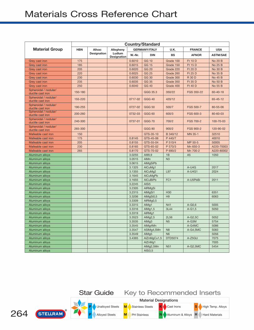
264 N
Material Designations
High Temp. Alloys
Hard Materials
Cast Irons
Aluminum & Alloys
Stainless Steels
PH Stainless
Unalloyed Steels
Alloyed Steels
Star Guide Key to Recommended Inserts
P M K S
HMP
Materials Cross Reference Chart
Country/StandardMaterial Group HBN Allvac Allegheny GERMANY/ITALY U.K. FRANCE USA
Designation Ludlum W.-Nr. DIN BS AFNOR ASTM/SAEDesignationGrey cast iron 175 0.6010 GG 10 Grade 100 Ft 10 D No 20 BGrey cast iron 185 0.6015 GG 15 Grade 150 Ft 15 D No 25 BGrey cast iron 205 0.6020 GG 20 Grade 220 Ft 20 D No 30 BGrey cast iron 220 0.6025 GG 25 Grade 260 Ft 25 D No 35 BGrey cast iron 230 0.6030 GG 30 Grade 300 R 30 D No 45 BGrey cast iron 235 0.6035 GG 35 Grade 350 Ft 35 D No 50 BGrey cast iron 250 0.6040 GG 40 Grade 400 Ft 40 D No 55 BSpheroidal / nodular/
150-180 GGG 35.3 350/22 FGS 350-22 60-40-18ductile cast ironSpheroidal / nodular/ 155-220 0717-02 GGG 40 420/12 65-45-12ductile cast ironSpheroidal / nodular/
190-255 0727-02 GGG 50 500/7 FGS 500-7 80-55-06ductile cast ironSpheroidal / nodular/
200-260 0732-03 GGG 60 600/3 FGS 600-3 80-60-03ductile cast ironSpheroidal / nodular/
240-300 0737-01 GGG 70 700/2 FGS 700-2 100-70-03ductile cast ironSpheroidal / nodular/
265-300 GGG 80 900/2 FGS 900-2 120-90-02ductile cast ironMalleable cast iron 150 GTS-35-10 B 340/12 MN 35-1 32510Malleable cast iron 175 0.8145 GTS-45-06 P 440/7 40010Malleable cast iron 205 0.8155 GTS-55-04 P 510/4 MP 50-5 50005Malleable cast iron 230 0.8165 GTS-65-02 P 570/3 Mn 650-3 A220-70003Malleable cast iron 265 0.8170 GTS-70-02 P 690/2 Mn 700-2 A220-80002Aluminum alloys 3.0255 Al99,9 1B A5 1050Aluminum alloys 3.0515 AlMn N3Aluminum alloys 3.0615 AlMgSiPbAluminum alloys 3.1325 AlCuMg1 A-U4G 2017Aluminum alloys 3.1355 AlCuMg2 L97 A-U4G1 2024Aluminum alloys 3.1645 AlCuMgPbAluminum alloys 3.1655 AlCuBiPb FC1 A-U5PbBi 2011Aluminum alloys 3.2245 AlSi5Aluminum alloys 3.2305 AlRMgSiAluminum alloys 3.2315 AlMgSi1 H30 6351Aluminum alloys 3.3206 AlMgSi0,5 H9 6063Aluminum alloys 3.3309 AlRMg0,5Aluminum alloys 3.3315 AlMg1 N41 A-G0,6 5005Aluminum alloys 3.3316 AlMg1,5 3L44 A-G1,5 5050Aluminum alloys 3.3319 AlRMg1Aluminum alloys 3.3523 AlMg2,5 2L56 A-G2,5C 5052Aluminum alloys 3.3535 AlMg3 N5 A-G3M 5754Aluminum alloys 3.3545 AlMg4Mn A-G4MC 5086Aluminum alloys 3.3547 ASlMg4,5Mn N8 A-G4,5MC 5083Aluminum alloys 3.3549 AlMg5 N6 5056Aluminum alloys 3.4365 AlZnMgCu1,5 DTD5074 A-Z5GU 7075Aluminum alloys AlZnMg1 7005Aluminum alloys AlMg2,5Mn N51 A-G2,5MC 5454Aluminum alloys AlSi3,5

265N
Material Designations
High Temp. Alloys
Hard Materials
Cast Irons
Aluminum & Alloys
Stainless Steels
PH Stainless
Unalloyed Steels
Alloyed Steels
Star Guide Key to Recommended Inserts
P M K S
HMP
Materials Cross Reference Chart
Si Fe Cu Mn Mg Cr Zn Ti
0.25 0.4 0.05 0.05 0.05 0.07 0.050.5 0.7 0.1 1.2 0.3 0.1 0.2 0.11.0 0.5 0.1 0.7 0.9 0.3 0.3 0.20.5 0.7 4.0 0.7 0.7 0.1 0.250.5 0.5 4.3 0.6 1.5 0.1 0.25 0.150.8 0.8 4.0 0.75 1.1 0.1 0.8 0.20.4 0.7 5.5 0.35.0 0.4 0.05 0.1 0.1 0.2 0.250.55 0.15 0.02 0.45 0.151.0 0.5 0.1 0.6 0.9 0.25 0.2 0.10.45 0.15 0.1 0.1 0.45 0.05 0.15 0.10.01 0.008 0.35 0.01 0.0080.3 0.45 0.05 0.15 0.9 0.1 0.20.4 0.45 0.05 0.15 1.5 0.1 0.20.1 0.008 1.00 0.01 0.0080.25 0.4 0.1 0.1 2.5 0.2 0.10.4 0.4 0.1 0.5 3.1 0.3 0.2 0.150.4 0.5 0.1 0.45 4.0 0.15 0.25 0.150.4 0.4 0.1 0.7 4.5 0.15 0.25 0.150.2 0.35 0.15 0.35 4.5 0.1 0.25 0.10.4 0.5 1.6 0.3 2.5 0.23 5.5 0.20.35 0.4 0.1 0.45 1.4 0.13 4.5 0.030.4 0.4 0.05 0.75 2.7 0.1 0.1 0.154.5 0.04
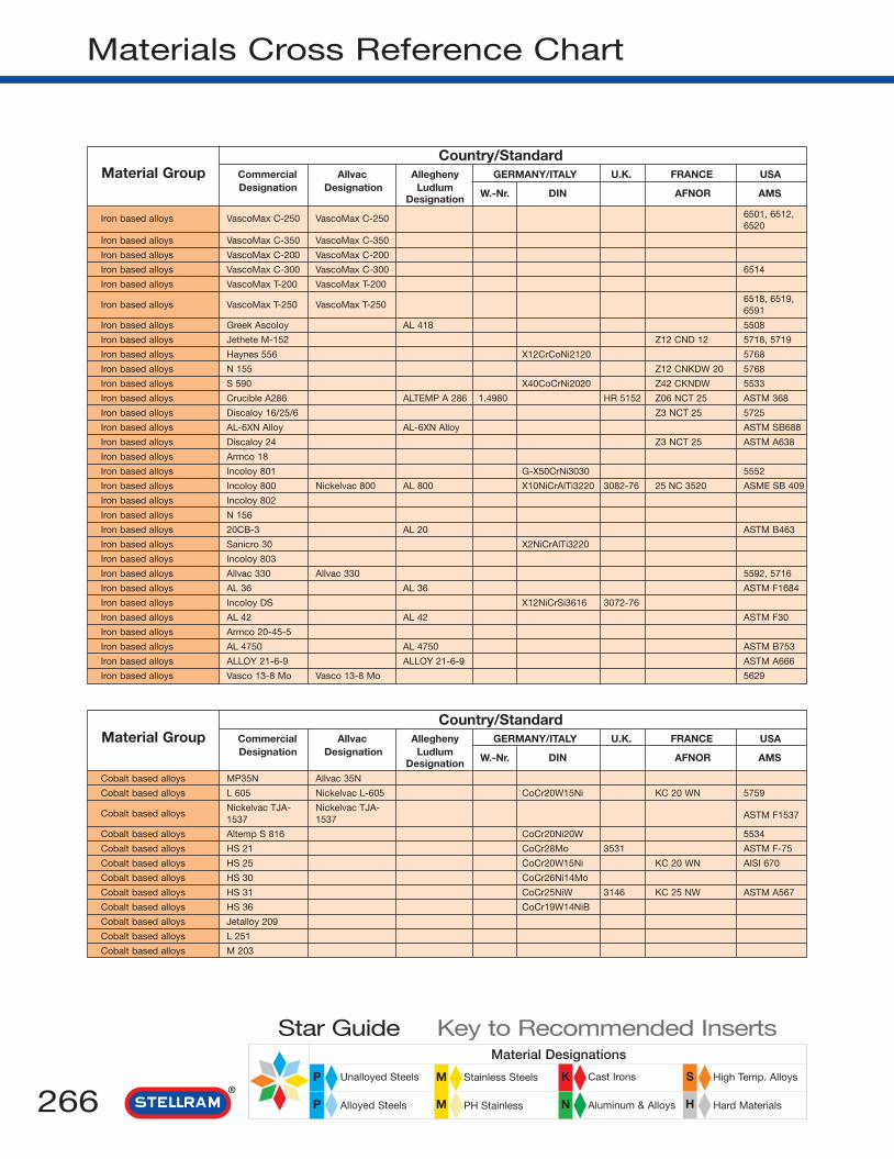
266 N
Material Designations
High Temp. Alloys
Hard Materials
Cast Irons
Aluminum & Alloys
Stainless Steels
PH Stainless
Unalloyed Steels
Alloyed Steels
Star Guide Key to Recommended Inserts
P M K S
HMP
Materials Cross Reference Chart
Country/StandardMaterial Group Commercial Allvac Allegheny GERMANY/ITALY U.K. FRANCE USA
Designation Designation Ludlum W.-Nr. DIN AFNOR AMSDesignation
Iron based alloys VascoMax C-250 VascoMax C-250 6501, 6512,6520
Iron based alloys VascoMax C-350 VascoMax C-350
Iron based alloys VascoMax C-200 VascoMax C-200
Iron based alloys VascoMax C-300 VascoMax C-300 6514
Iron based alloys VascoMax T-200 VascoMax T-200
Iron based alloys VascoMax T-250 VascoMax T-2506518, 6519,6591
Iron based alloys Greek Ascoloy AL 418 5508
Iron based alloys Jethete M-152 Z12 CND 12 5718, 5719
Iron based alloys Haynes 556 X12CrCoNi2120 5768
Iron based alloys N 155 Z12 CNKDW 20 5768
Iron based alloys S 590 X40CoCrNi2020 Z42 CKNDW 5533
Iron based alloys Crucible A286 ALTEMP A 286 1.4980 HR 5152 Z06 NCT 25 ASTM 368
Iron based alloys Discaloy 16/25/6 Z3 NCT 25 5725
Iron based alloys AL-6XN Alloy AL-6XN Alloy ASTM SB688
Iron based alloys Discaloy 24 Z3 NCT 25 ASTM A638
Iron based alloys Armco 18
Iron based alloys Incoloy 801 G-X50CrNi3030 5552
Iron based alloys Incoloy 800 Nickelvac 800 AL 800 X10NiCrAlTi3220 3082-76 25 NC 3520 ASME SB 409
Iron based alloys Incoloy 802
Iron based alloys N 156
Iron based alloys 20CB-3 AL 20 ASTM B463
Iron based alloys Sanicro 30 X2NiCrAlTi3220
Iron based alloys Incoloy 803
Iron based alloys Allvac 330 Allvac 330 5592, 5716
Iron based alloys AL 36 AL 36 ASTM F1684
Iron based alloys Incoloy DS X12NiCrSi3616 3072-76
Iron based alloys AL 42 AL 42 ASTM F30
Iron based alloys Armco 20-45-5
Iron based alloys AL 4750 AL 4750 ASTM B753
Iron based alloys ALLOY 21-6-9 ALLOY 21-6-9 ASTM A666
Iron based alloys Vasco 13-8 Mo Vasco 13-8 Mo 5629
Country/StandardMaterial Group Commercial Allvac Allegheny GERMANY/ITALY U.K. FRANCE USA
Designation Designation Ludlum W.-Nr. DIN AFNOR AMSDesignationCobalt based alloys MP35N Allvac 35N
Cobalt based alloys L 605 Nickelvac L-605 CoCr20W15Ni KC 20 WN 5759
Cobalt based alloysNickelvac TJA- Nickelvac TJA-
ASTM F15371537 1537
Cobalt based alloys Altemp S 816 CoCr20Ni20W 5534
Cobalt based alloys HS 21 CoCr28Mo 3531 ASTM F-75
Cobalt based alloys HS 25 CoCr20W15Ni KC 20 WN AISI 670
Cobalt based alloys HS 30 CoCr26Ni14Mo
Cobalt based alloys HS 31 CoCr25NiW 3146 KC 25 NW ASTM A567
Cobalt based alloys HS 36 CoCr19W14NiB
Cobalt based alloys Jetalloy 209
Cobalt based alloys L 251
Cobalt based alloys M 203

267N
Material Designations
High Temp. Alloys
Hard Materials
Cast Irons
Aluminum & Alloys
Stainless Steels
PH Stainless
Unalloyed Steels
Alloyed Steels
Star Guide Key to Recommended Inserts
P M K S
HMP
Materials Cross Reference Chart
Ni Co Cr Mo W Si Mn C Al Ti P S Others
18.5 7.8 4.8 0.05 0.05 0.02 0.1 0.4 0.005 0.005
18.5 12.0 4.8 0.05 0.05 0.02 0.1 1.4 0.005 0.005
18.5 8.5 3.25 0.05 0.05 0.01 0.2 0.005 0.005
18.5 8.8 4.8 0.05 0.05 0.02 0.1 0.73 0.005 0.005
18.5 3.0 0.05 0.05 0.01 0.7 0.005 0.005
18.5 3.0 0.03 0.05 0.02 0.1 1.4 0.005 0.005
2 12 2.5 0.19
2.5 12 1.7 0.15 V 0.3
20 20 21 3 2.5 0.1 Nb + Ta
20 20 21 3 2.5 0.5 1.5 0.15 Nb 1.0
20 20 21 4 4 0.43
25 14 1.3 0.5 1.3 0.05 0.2 2.1
25 16 6 0.7 1.35 0.12 0.3 Nb 0.4
25 20.5 6.5 0.02 N 0.2
26 13.5 2.7 0.8 0.9 0.04 0.1 1.7
3.7 17.2 0.47 12.5 0.06
32 20.5 0.5 0.8 0.05 1.1
32.5 21.0 0.5 0.75 0.05 0.37 0.37 0.007 Cu 0.37
32.5 21.5 0.4 0.8 0.4
33 24 17 3 2 0.33
33 20 2.2 Cu 3.3
34 22 0.55 0.55 0.03 0.3 0.5 Cu 0.1
35 25 0.08 0.15 0.15
35.5 18.5 1.13 1.0 0.04 0.01 0.01 Cu 0.5
36
37 18 2.3 1.0 0.06
41
46 20 2.3 1.0 5 0.08 Nb 0.4
49
6.5 21 6.0 No 0.3
8.0 12.8 2.3 0.05 0.10 0.03 1.05 0.005 0.004
Ni Co Cr Mo W Si Mn C Al Ti P S Others
35 20 9.8 0.013
10 0.5 20 15 1.7 0.1
0.2 0.25 28 6 0.5 0.5 0.06 N 0.2
20 4 20 4 4 0.4 1.2 0.383 1 27 5 0.6 0.6 0.2510 3 20 15 2 1.5 0.116 1 24 6 0.6 0.6 0.410 1.5 25 8 0.75 0.6 0.410 2 18 15 1.5 0.410 1 20 15 2.0 0.0210 1 19 14 0.4
24.5 1 19.5 12 1 0.8 2.15 24.5 0.07
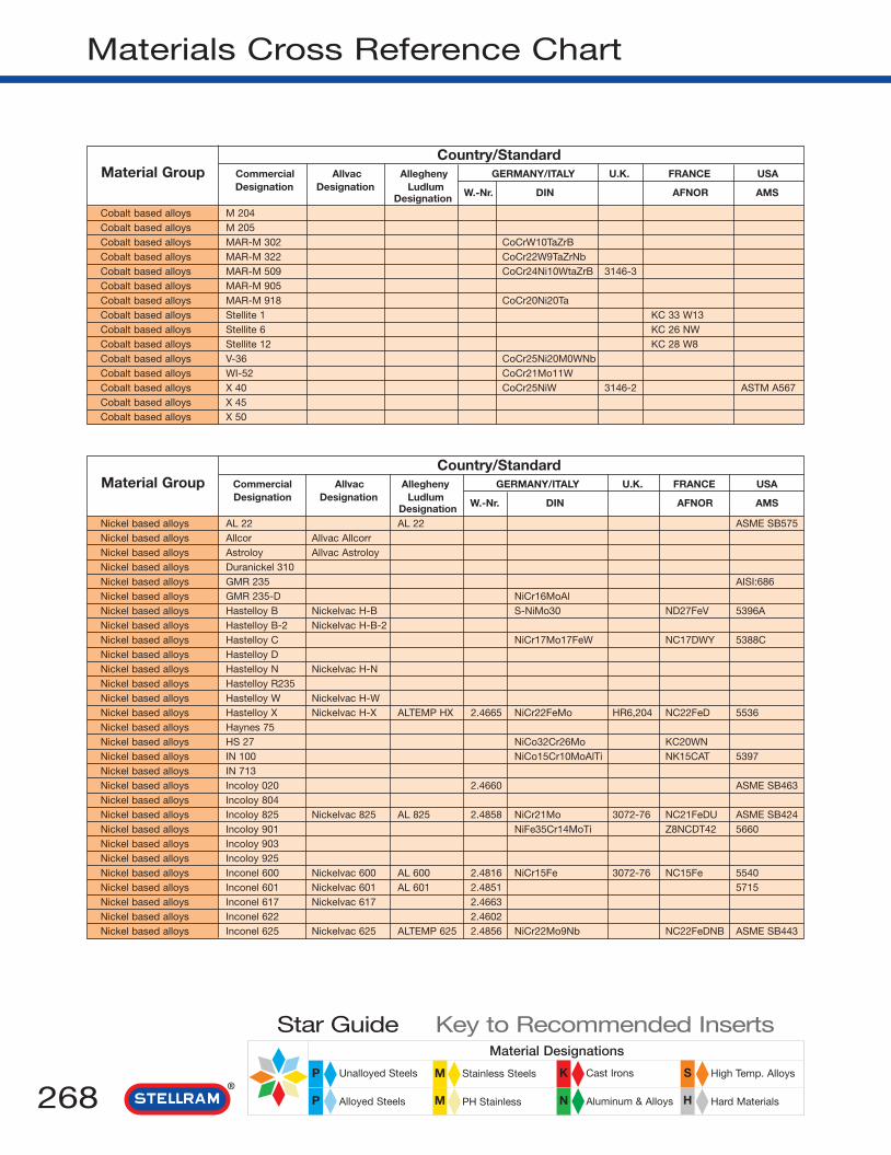
268 N
Material Designations
High Temp. Alloys
Hard Materials
Cast Irons
Aluminum & Alloys
Stainless Steels
PH Stainless
Unalloyed Steels
Alloyed Steels
Star Guide Key to Recommended Inserts
P M K S
HMP
Materials Cross Reference Chart
Country/StandardMaterial Group Commercial Allvac Allegheny GERMANY/ITALY U.K. FRANCE USA
Designation Designation Ludlum W.-Nr. DIN AFNOR AMSDesignationCobalt based alloys M 204Cobalt based alloys M 205Cobalt based alloys MAR-M 302 CoCrW10TaZrBCobalt based alloys MAR-M 322 CoCr22W9TaZrNbCobalt based alloys MAR-M 509 CoCr24Ni10WtaZrB 3146-3Cobalt based alloys MAR-M 905Cobalt based alloys MAR-M 918 CoCr20Ni20TaCobalt based alloys Stellite 1 KC 33 W13Cobalt based alloys Stellite 6 KC 26 NWCobalt based alloys Stellite 12 KC 28 W8Cobalt based alloys V-36 CoCr25Ni20M0WNbCobalt based alloys WI-52 CoCr21Mo11WCobalt based alloys X 40 CoCr25NiW 3146-2 ASTM A567Cobalt based alloys X 45Cobalt based alloys X 50
Country/StandardMaterial Group Commercial Allvac Allegheny GERMANY/ITALY U.K. FRANCE USA
Designation Designation Ludlum W.-Nr. DIN AFNOR AMSDesignationNickel based alloys AL 22 AL 22 ASME SB575Nickel based alloys Allcor Allvac AllcorrNickel based alloys Astroloy Allvac AstroloyNickel based alloys Duranickel 310Nickel based alloys GMR 235 AISI:686Nickel based alloys GMR 235-D NiCr16MoAlNickel based alloys Hastelloy B Nickelvac H-B S-NiMo30 ND27FeV 5396ANickel based alloys Hastelloy B-2 Nickelvac H-B-2Nickel based alloys Hastelloy C NiCr17Mo17FeW NC17DWY 5388CNickel based alloys Hastelloy DNickel based alloys Hastelloy N Nickelvac H-NNickel based alloys Hastelloy R235Nickel based alloys Hastelloy W Nickelvac H-WNickel based alloys Hastelloy X Nickelvac H-X ALTEMP HX 2.4665 NiCr22FeMo HR6,204 NC22FeD 5536Nickel based alloys Haynes 75Nickel based alloys HS 27 NiCo32Cr26Mo KC20WNNickel based alloys IN 100 NiCo15Cr10MoAlTi NK15CAT 5397Nickel based alloys IN 713Nickel based alloys Incoloy 020 2.4660 ASME SB463Nickel based alloys Incoloy 804Nickel based alloys Incoloy 825 Nickelvac 825 AL 825 2.4858 NiCr21Mo 3072-76 NC21FeDU ASME SB424Nickel based alloys Incoloy 901 NiFe35Cr14MoTi Z8NCDT42 5660Nickel based alloys Incoloy 903Nickel based alloys Incoloy 925Nickel based alloys Inconel 600 Nickelvac 600 AL 600 2.4816 NiCr15Fe 3072-76 NC15Fe 5540Nickel based alloys Inconel 601 Nickelvac 601 AL 601 2.4851 5715Nickel based alloys Inconel 617 Nickelvac 617 2.4663Nickel based alloys Inconel 622 2.4602Nickel based alloys Inconel 625 Nickelvac 625 ALTEMP 625 2.4856 NiCr22Mo9Nb NC22FeDNB ASME SB443

269N
Material Designations
High Temp. Alloys
Hard Materials
Cast Irons
Aluminum & Alloys
Stainless Steels
PH Stainless
Unalloyed Steels
Alloyed Steels
Star Guide Key to Recommended Inserts
P M K S
HMP
Materials Cross Reference Chart
Ni Co Cr Mo W Si Mn C Al Ti P S Others
24.5 18.5 12 1 1 0.0724.5 18.5 12 2.75 0.07
21.5 10 0.85 Ta 9.021.5 9 0.1 0.1 0.75 1.0 Ta 4.5, Zr 2.25
10 1 23.5 7 0.1 0.1 0.2 0.6 Ta 3.5, Zr 0.520 20 0.5 0.05 Ta 7.5, Zr 0.120 0.4 20 0.1 0.1 0.05 Ta 7.5, Zr 0.1
33 13 2.526 5 1.0 Nb 6.029 9 1.8
20 3 25 4 2 0.4 1 0.26 Nb 2.01 2 21 11 0.25 0.45 Nb 2.0
10.5 1.5 25.5 7.5 0.75 0.75 0.510.5 2 25.5 7 0.7 0.25 B 0.0120.5 4 22.5 12 0.75
Ni Co Cr Mo W Si Mn C Al Ti P S Others
2.5 20.6 13.9 2.6531.0 10.0 2.0 0.02 0.25 0.25 Nb 0.4
17.0 15.0 5.0 0.04 4.0 3.5 B 0.0250.6 0.5 1.0 0.5 4.4 0.610.0 15.5 5.2 0.4 0.2 0.15 3.0 2.04.5 15.5 5.0 0.15 3.5 2.5 B0.055.0 2.0 1.5 28.0 0.05 0.5 0.02 V 0.41.0 0.5 0.5 16.0 0.05 0.5 0.01 0.02 0.0156.0 2.0 15.0 17.0 5 0.042.0 1.0 9.0 1.0 0.1 Cu 3.04.0 7.0 16.5 0.0210.0 2.5 15.5 5.5 0.15 2 2.54.0 5.0 24.5 0.0218 1.5 22 9.0 0.6 0.15.0 20.0 0.12 0.25 0.4 Cu 0.52.0 31.5 26.0 6.0 0.4
15.0 10.0 3.0 0.18 5.5 4.7 V 1.02.5 13.0 4.6 0.4 0.2 0.18 6.0 0.8 Nb 2.637 20 2.5 Nb 0.6 Cu 3.5
25.4 29.5 0.5 0.75 0.06 0.25 0.6 Cu 0.430 21.5 3.0 0.5 0.65 0.03 0.2 0.9 Cu 2.25
35.3 13.45 6.20 0.22 0.48 0.05 2.542.0 15.0 0.7 1.4 Nb3.028 21 3 0.3 2.1 Cu 1.88.0 15.5 0.07514.0 23.0 0.2 0.5 0.05 1.3 0.008 Cu 0.5
12.5 22 9.0 0.07 1.02.3 20.5 14.2 3.22.5 21.5 9.0 0.05 0.3 0.3 Cb 3.7

270 N
Material Designations
High Temp. Alloys
Hard Materials
Cast Irons
Aluminum & Alloys
Stainless Steels
PH Stainless
Unalloyed Steels
Alloyed Steels
Star Guide Key to Recommended Inserts
P M K S
HMP
Materials Cross Reference Chart
Country/StandardMaterial Group Commercial Allvac Allegheny GERMANY/ITALY U.K. FRANCE USA
Designation Designation Ludlum W.-Nr. DIN AFNOR AMSDesignationNickel based alloys Inconel 690 Nickelvac 690 2.4642
Nickel based alloys Inconel 700 NiCo28Cr15MoAlTi NK27CADT
Nickel based alloys Inconel 702 5550
Nickel based alloys Inconel 706 Allvac 706 57-2
Nickel based alloys Inconel 713 G-NiCr13Al16MoNb 3146.3 NC13AD 5391
Nickel based alloys Inconel 718 Allvac 718 ALTEMP 718 2.4668 NiCr19Fe19NbMo HR8 NC19FeNb 5383
Nickel based alloys Inconel 718-OP Allvac 718-OP
Nickel based alloys Inconel 720 Allvac 720
Nickel based alloys Inconel 721
Nickel based alloys Inconel 722 Nickelvac W-722 NiCr16FeTi NC16Feti 5541
Nickel based alloys Inconel 725
Nickel based alloys Inconel 751 Nickelvac X-751 2.4694
Nickel based alloys Inconel X-750 Nickelvac X-750 ALTEMP 750 2.4669 NiCr16FetTi NC15FeTNb 5542
Nickel based alloys Jessop G 81 NiCr20Co18Ti
Nickel based alloys Jethete M-252 Allvac M-252 G-NiCr19Co 5551
Nickel based alloys MAR-M 200 NiW13Co10Cr9AlTi NKW10CATaHf
Nickel based alloys MAR-M 246 NiCo10W10Cr9AlTi
Nickel based alloys MAR-M 421 NiCr16Co10WalTi
Nickel based alloys MAR-M 432 NiCo20Cr16WAlTi
Nickel based alloys Monel 400 Nickelvac 400 AL 400 2.4360 NiCu30Fe 3072-76 NU30 4544
Nickel based alloys Monel K 500 Nickelvac K-500 2.4375 NiCu30Al 3072-76 4676
Nickel based alloys Monel R 405 4674
Nickel based alloys Nimocast 713 G-NiCr13A16MoNb HC203 NC13AD 5391A
Nickel based alloys Nimocast PD 16 NiFe33Cr17Mo
Nickel based alloys Nimocast PE 10 HC202 NC20N13
Nickel based alloys Nimonic 105 2.4634 NiCo20Cr15MoAlTi HR3 NCKD20ATV
Nickel based alloys Nimonic 115 2.4636 NiCo15Cr15MoAlTiHR401,
NCVK15ATD601
Nickel based alloys Nimonic 75 2.4630 NiCr20TiHR5,
NC20T203-4
Nickel based alloys Nimonic 80A Nickelvac 80 A 2.4631 NiCr20TiAlHR401,
NC20TA601
Nickel based alloys Nimonic 86
Nickel based alloys Nimonic 90 Nickelvac N-90 2.4632 NiCr20Co18Ti HR2,202 NCK20TA
Nickel based alloys Nimonic 901 Nickelvac 901 2.4662 NiCr15MoTi Z8NCDT42 5660, 5661
Nickel based alloys Nimonic 95
Nickel based alloys Nimonic C-22 Nickelvac C-22
Nickel based alloys Nimonic C-263 Nickelvac C-263 ALTEMP 263 2.4650 NiCr20CoMoTi HR10 NCK20D
Nickel based alloys Nimonic C-276 Nickelvac C-276 AL 276 2.4819 ASME SB575
Nickel based alloys Nimonic PE 13 NiCr22Fe18Mo HR6,204 NC22FeD 5536E
Nickel based alloys Nimonic PE 16 NiFe33Cr17Mo HR207 NW11AC
Nickel based alloys Nimonic PK 25 NKCD20ATU 5751A
Nickel based alloys Nimonic PK 31
Nickel based alloys Nimonic PK 33 NiCr20Co16MoTi 5057 NC19KDU/V
Nickel based alloys R-235
Nickel based alloys Refractaloy 26 Z6NKCDT38 AISI:690
Nickel based alloys René 100 NiCo15Cr10MoAlTi
Nickel based alloys René 125
Nickel based alloys René 41 Rene 41 NiCr19Co11MoTi NC19KDT 5712, 5713
Nickel based alloys René 63

271N
Material Designations
High Temp. Alloys
Hard Materials
Cast Irons
Aluminum & Alloys
Stainless Steels
PH Stainless
Unalloyed Steels
Alloyed Steels
Star Guide Key to Recommended Inserts
P M K S
HMP
Materials Cross Reference Chart
Fe Co Cr Mo W Si Mn C Al Ti P S Others
9.0 29.0 0.2 0.2 0.25 0.007 Cu 0.2
0.7 28.5 15 3.7 0.3 0.1 0.12 3.0 2.2
0.4 15.6 0.2 0.05 0.04 3.4 0.7
16.0 0.03 1.8 Cb 2.9
12 4.5 0.13 6 0.6
17.2 19.0 3.1 0.02 0.5 0.9 Cb 5.2
17.2 19.0 3.1 0.02 0.5 0.9 Cb 5.2
14.7 18 3 1.25 2.5 5
8.0 16 0.15 2.25 0.07 0.1 3.0 Cu0.2
7.0 15.5 0.04 0.7 2.4
7.5 21 8 0.3 1.5 Nb 3.5
7.0 15.5 0.2 0.5 0.05 1.2 2.3 0.005 Cb 1.1, Cu 0.2
7.0 15.5 0.04 0.7 2.5 Cb 0.95
0.5 16.9 20.6 0.2 0.5 0.08 1.5 2.5
2.5 10.0 19.0 9.75 0.15 1.0 2.5 B 0.007
10.0 9.0 12.5 0.15 5.0 2.0 Nb1.0
10.0 9.0 2.5 10.0 0.15 5.5 1.5 Ta1.5
10.0 15.5 1.7 3.5 0.15 4.25 1.75 Nb1.75
20.0 15.5 3 0.15 2.5 4.3 Nb2.0
1.2 0.25 0.15 0.01
1.0 0.25 0.7 0.1 2.7 0.6 0.01
1.25 0.25 1.0 0.15 Cu31.5
13.5 4.5 0.12 6.0 0.9
34.0 16.5 3.3 0.06 1.2 1.2
3.0 20.0 6.0 2.5 0.03
0.5 20 14.75 5 0.5 0.5 0.1 4.7 1.2 Cu
13.2 14.2 4 0.16 5 4 Zr
4 20 0.45 0.45 0.45 0.1 0.35 Cu+S
0.55 19.5 0.2 0.55 0.08 1.4 2.4 Cu+S
25 10 Ce 0.03
0.3 18.0 19.5 0.065 1.4 2.4
35.0 12.5 6.0 0.05 2.8 B 0.015
5.0 18.0 19.5 1.0 1.0 0.1 2.0 3.5
4.0 1.2 21.2 13.5 3.0 0.04 0.2 0.07 0.01 V 0.17
20.0 20.0 5.85 0.06 0.45 2.15
5.0 0.5 15.5 16.0 3.5 0.01
18.5 1.5 21.75 9 0.6 0.5 0.5 0.1
1.2 16.5 3.5 0.05 1.2 1.2
19.5 19 4 0.75 0.75 0.08 2.9 2.9 B 0.01
14 20 4.5 0.4 2.3 Nb5
0.5 14 18 7 0.25 0.25 0.05 2.1 2
10.0 1.15 15.0 5.5 0.3 0.1 0.12 20 2.5
16.0 20.0 18.0 3.2 1.0 0.8 0.03 0.2 2.8
15.0 10.0 3.0 0.18 5.5 4.7 V1.0
10.0 8.9 2.0 7.0 0.1 4.7 2.5 Hf1.05, Ta3.0
3.0 11.0 19.0 9.75 0.06 1.6 2.5 B 0.007
3.5 15.0 14.0 6.0 3.5 0.2 0.1 0.05 3.8 2.5

272 N
Material Designations
High Temp. Alloys
Hard Materials
Cast Irons
Aluminum & Alloys
Stainless Steels
PH Stainless
Unalloyed Steels
Alloyed Steels
Star Guide Key to Recommended Inserts
P M K S
HMP
Materials Cross Reference Chart
Country/StandardMaterial Group Commercial Allvac Allegheny GERMANY/ITALY U.K. FRANCE USA
Designation Designation Ludlum W.-Nr. DIN AFNOR AMSDesignationNickel based alloys René 77Nickel based alloys René 80Nickel based alloys René 95 NC14K8Nickel based alloys TRW VIA NiTa9Co8W6CrAlNickel based alloys Udimet 500 NiCr18CoMoAlTi NCK19DAT AISI:684Nickel based alloys Udimet 520 Allvac 520Nickel based alloys Udimet 630 NiCr19NbMoNickel based alloys Udimet 700 NiCo15Cr15MoAlTi NCKD20AT AISI:687Nickel based alloys Udimet 710 NCK18TDANickel based alloys Udimet 718 NiCr19Fe19NbMo HR8 NC19FeNb 5583Nickel based alloys Waspaloy Allvac Waspaloy 2.4654 NiCr20Co14MoTi NC20K14 5544
Country/StandardMaterial Group Commercial Allvac Allegheny GERMANY/ITALY U.K. FRANCE USA
Designation Designation Ludlum W.-Nr. DIN AFNOR AMSDesignationAlpha Titanium alloys Ti-5Al-2.5Sn Allvac 5-2.5 TiAl5Sn2 TA 14,17 T-A5E ASTM: B 265
Alpha Titanium alloys Ti-7Al-4Mo TiAl7Mo4 ASTM: B 381
Alpha Titanium alloys Ti-8Al-1Mo-1V Allvac 8-1-1 TiAl8Mo1V1 4915, 4933, 4972
Alpha Titanium alloys Ti-6Al-4Zr-2Mo-2Sn Allvac 6-2-4-2 TiAl6Zr4Mo2Sn2 4919, 4975, 4976
Alpha Beta Titanium alloys Ti-6Al-4V Allvac 6-4 TiAl6V4TA 10-13
T-A6V4906, 4920,4928,
TA 28 4965, 4967
Alpha Beta Titanium alloys Ti-6Al-6V-2Sn Allvac 6-6-2 TiAl6V6Sn2 4971
Alpha Beta Titanium alloys Ti-4Al-4Mo-2Sn-0.5Si Allvac 4-4-2 TiAl4Mo4Sn2Si0.5 5103 T-A4DE
Alpha Beta Titanium alloys Ti-4Al-4Mo-4Sn-0.5Si TiAl4Mo4Sn4Si0.5 5203
Alpha Beta Titanium alloys Ti-7Al-4Mo TiAl7Mo4 ASTM: B 381
Alpha Beta Titanium alloysTi-6Al-5Zr-0.5Mo-
TiA6Zr5Mo0.5Si0.25 T-AGZ-500.25Si
Alpha Beta Titanium alloysTi-6Al-5Zr-4Mo-Cu-
TiAl6Zr5Mo4CuSi0.2 M2010.2Si
Alpha Beta Titanium alloys Allvac 3-2.5 Allvac 3-2.5 4943, 4944
Alpha Beta Titanium alloys Allvac 6-4ELI Allvac 6-4ELI 4907, 4930, 4931
Alpha Beta Titanium alloys Allvac 6-2-4-6 Allvac 6-2-4-6 4981
Alpha Beta Titanium alloys Allvac Ti-17 Allvac Ti-17 4995
Beta Titanium alloys Ti-13V-11Cr-3Al Allvac 13-11-3 TiV13Cr11Al3 4917
Beta Titanium alloys Ti-8Mo-8V-2Fe-3Al
Beta Titanium alloysTi-3Al-8V-6Cr-4Mo-
Allvac 38-6444Zr
Beta Titanium alloys Ti-11.5Mo-6Zr-4.5Sn
Pure Titanium Ti 99.5 Allvac 70, Ti CP-4 Ti 99.5 TA 6 AIR: 9182 T60 ASTM: B381F4
Pure Titanium Ti 99.6 Allvac 55, Ti CP-3 Ti 99.6 AIR: 9182 T50 ASTM: B381F3
Pure Titanium Ti 99.7 Allvac 40, Ti CP-2 Ti 99.7a TA 2-5 AIR: 9182 T40 ASTM: B381F2
Pure Titanium Ti 99.8 Allvac 30, Ti CP-1 Ti 99.8 TA 1 AIR: 9182 T35 ASTM: B381F1
Austempered ductile iron 269-321 EN-GJS-800-8 125/80/10 (grade 1)
Austempered ductile iron 269-321 EN-JS1100 850/550/10 (grade 1)
Austempered ductile iron 302-363 EN-GJS-1000-5 150/100/7 (grade 2)
Austempered ductile iron 302-363 EN-JS1110 1050/700/7 (grade 2)
Austempered ductile iron 341-444 EN-GJS-1200-2 175/125/4 (grade 3)
Austempered ductile iron 341-444 EN-JS1120 1200/850/4 (grade 4)
Austempered ductile iron 444-555 EN-GJS-1400-1 230/185/--- (grade 5)
Austempered ductile iron 444-555 EN-JS-11301600/1300/--(grade 5)

273N
Material Designations
High Temp. Alloys
Hard Materials
Cast Irons
Aluminum & Alloys
Stainless Steels
PH Stainless
Unalloyed Steels
Alloyed Steels
Star Guide Key to Recommended Inserts
P M K S
HMP
Materials Cross Reference Chart
Fe Co Cr Mo W Si Mn C Al Ti P S Others
0.4 15.0 15.0 4.2 0.1 0.1 0.07 4.3 3.39.5 14.0 4.0 4.0 0.17 3.0 5.08.0 14.0 3.5 3.5 0.15 3.5 2.5 Nb3.57.5 6.0 2.0 5.8 0.13 5.4 1.0 Nb0.5, Ta9.019.0 4.0 0.1 0.1 0.07 3.0 3.012 19 6 1 2 3
18.0 18.0 3.0 0.03 0.5 1.0 Nb6.516.5 15.0 5.0 0.07 4.4 3.415.0 18.0 3.0 1.5 0.07 2.5 5.0
18.0 18.0 3.0 0.05 0.6 1.0 Nb+Ta5.213.0 19.5 4.3 0.05 1.40 3.0 Zr .07
Al Sn Mo V Zr Si Others
5.0 2.57.0 4.08.0 1.0 1.06.0 2.0 2.0 4.0
6.0 4.0
5.5 2.0 5.54.0 2.0 4.0 0.554.0 4.0 4.0 0.57.0 4.0 Fe 0.3
6.0 0.5 5.0 0.25
6.0 4.0 5.0 0.2 Cu 1.0
3.0 2.5 Fe 0.136.0 Fe 0.26.0 2.0 6.0 4.0 Fe 0.105.0 2.0 4.0 2.0 Cr 4.03.0 13.0 Cr 11.03.0 8.0 8.0
3.0 4.0 8.0 4.0 Cr 6.0
4.5 11.5 6.0
Waspaloy is a registered trademark of Pratt & Whitney Aircraft.Vasco, VascoMax, Jethete, Nickelvac, Rene, Allvac and VascoJet are registered trademarks of ATI Properties, Inc.d.b.a. Allvac.

274 N
Material Designations
High Temp. Alloys
Hard Materials
Cast Irons
Aluminum & Alloys
Stainless Steels
PH Stainless
Unalloyed Steels
Alloyed Steels
Star Guide Key to Recommended Inserts
P M K S
HMP
Alphanumeric Index
1Page
15 Geometry 21
1A Geometry 15
2Page
2B Geometry 15
2N Geometry 16
3Page
3F Geometry 16
3G Geometry 17, 24
3J Geometry 17
3M Geometry 18
4Page
4M Geometry 18
4T Geometry 19
4U Geometry 19
5Page
55° partial profile 207
5V Geometry 20
6Page
60° partial profile 206
61 Geometry 21
62 Geometry 22
64 Geometry 22
645 175
66 Geometry 23
676 175
7Page
73 Geometry 23
APage
ACME thread form 223
Amer. Buttress thread form 231
Amer. UN thread form 211 - 213
API thread form 232 - 237
ASCLC 146
ASDUC 148
ASDXC 150
ASDZC 151
ASELP 152
ASSKC 153
ASTUC 154
ASVQC 156
ASVUC 157
ASWLP 158
BPage
BA thread form 222
British Buttress thread form 230
BSPT thread form 221
CPage
CCGT 38
CCMT 39
CISCLC 146
CISCLP 147
CISTUP 155
CNGP 40
CNMA 41
CNMG 41 - 45
CNMM 45
CPG 46
CPMT 47
DPage
DCGT 48 - 49
DCMT 49 - 50
DCMW 50
DNGP 51
DNMA 52
DNMG 52 - 55

275N
Material Designations
High Temp. Alloys
Hard Materials
Cast Irons
Aluminum & Alloys
Stainless Steels
PH Stainless
Unalloyed Steels
Alloyed Steels
Star Guide Key to Recommended Inserts
P M K S
HMP
Alphanumeric Index
EPage
ECMT 56
EPEW 57
EPEX 58 - 59
EPGT 59
EPMT 60
EPMW 60
EPMX 61
ER Threading Holder 239
FPage
FNAS 189
FNE 190
FNG 183
FNGP 184
FNP 184
FNR 186
FNRP 187
FNS 191
FNT 185
FNTF 185
FNTP 186
GPage
GH1 Grade 27
GH2 Grade 27
HPage
H21 Grade 27
IPage
IR Threading Holder 240 - 241ISO thread form 208 - 210
MPage
M Geometry 24
MCGN 100
MCKN 101 & 139
MCLN 102 & 140
MCRN 103
MDJN 104
MDPNN 105
MDQN 141
MDUN 142
MJ thread form 229
MP37 Grade 26
MRGN 106
MSDNN 107
MSKN 108 & 143
MSRN 109
MSSN 110
MTENN 111
MTFN 112
MTJN 113
MVJN 114
MVPN 115
MVUN 144
MVVNN 116
MWLN 117 & 145
NPage
NL25 Grade 26
NL30 Grade 26
NL37 Grade 26
NL40 Grade 26
NL92 Grade 26
NPT thread form 217 - 218
NPTF thread form 219 - 220
PPage
PG thread form 227
RPage
R004 177, 180
R005 178, 180
R006 178, 180
R007 179 - 180
R050 176
R060 177
R070 177
RCEW 62
RCMT 62 - 63
RD-C 63
RNMG 64
Round thread form 226

276 N
Material Designations
High Temp. Alloys
Hard Materials
Cast Irons
Aluminum & Alloys
Stainless Steels
PH Stainless
Unalloyed Steels
Alloyed Steels
Star Guide Key to Recommended Inserts
P M K S
HMP
Alphanumeric Index
SPage
SAGE thread form 203SBET 65SC1519 Grade 26SCAC 118SCLC 119 & 146SCLP 120 & 147SCMT 66 - 67SCMW 67SCMX 67SDAC 121SDJC 122SDNC 123SDUC 148SDWC 149SDXC 150SDZC 151SEAP 124SELP 152S-FNE 192SFZ Grade 27SGIH 194SIMCKN 139SIMCLN 140SIMDQN 141SIMDUN 142SIMSKN 143SIMVUN 144SIMWLN 145SISCLP 147SISTUP 155SNG 68SNMA 69SNMG 70 - 72SNMM 72SNU 68SP0864 Grade 27SP3036 Grade 27SP3064 Grade 27SP4036 Grade 27SP4064 Grade 27SPG 73
SPU 73SRCP 125SRCPN 126SRDC 127SSDC 128SSDWC 149SSKC 153SSWLP 158STACME thread form 224STBT 129STGC 130STGP 131STPOR 195STTL 196STTN 196STTR 196STUC 154STUP 155SVAC 132SVJB 133SVQC 156SVUC 157SVVC 134SWLP 158
TPage
T Geometry 25TCMT 74 - 75TCMW 75TCMX 75Technical Information 160TGTBN 194TGTL 195TGTN 195TGTR 195TNG 76TNMA 77TNMG 78 - 82TNMM 82
TPG 83TPU 84Trapezoidal thread form 225
UPage
UNJ thread form 228
VPage
VBMT 85VCGT 86 - 87VCGW 87VCMT 87VCMW 87VNGP 88VNMA 88VNMG 89 - 90VPGR 91VPMR 91
WPage
Whitworth thread form 214 - 216WNGP 92WNMA 92WNMG 93 - 95WPMT 95
XPage
X Geometry 25

Answering Your Tooling Needs
Milling
Stellram’s comprehensive tooling program issupported by a wealth of technical knowledge
and development across all products.
Drilling
Threading
Turning
Grooving
Part-Off
w w w. s t e l l r a m . c o m
TOLL FREE CUSTOMER SERVICE
UNITED STATESTEL: 800 232 1200FAX: 800 223 2219
CANADATEL: 800 668 6928FAX: 800 432 6227
MEXICOTEL: 011 877 756 0947FAX: 011 877 285 2505

LITERATURE RE-ORDER NUMBER
01/06 - PRINTED IN THE U.K.230CATUK.V1327CATUSA.V2
© 2006, Stellram, An Allegheny Technologies Company.
The Starburst Logo is a registered trademark of ATI Properties, Inc.
Stellram is a registered trademark of Stellram S.A.An Allegheny Technologies Company.
Aerostell, Posidisc and Posicut are registered trademarks of Stellram.
Star Guide and Metalcutting Answers are trademarks of Stellram.
All other trademarks are the property of their respective companies.
www.stellram.com
Metalcuttinganswers.TM
A S S O C I A T E D C O M P A N I E S
Australia
Austria
Belgium
Canada
Denmark
Finland
Holland
Japan
Mexico
New Zealand
Norway
Portugal
South Africa
South Korea
Sweden
Thailand
Allegheny Technologies Incorporated is one of the largest and most diversified specialty materials producers in the world. The Company’s talented people
use innovative materials and processing technologies to offer growing global markets a wide range of specialty materials solutions. High value products
include nickel-base and cobalt-base alloys and superalloys, titanium and titanium alloys, specialty steels, super stainless steels, exotic alloys, which include
zirconium, hafnium and niobium, tungsten materials, and highly engineered strip and Precision Rolled Strip® products. In addition, the Company produces
general-purpose specialty materials such as stainless steel sheet and plate, silicon and tool steels, and forgings and castings.
Allegheny Ludlum - Allegheny Rodney, Shanghai STAL, Rome Metals. Allvac - Alvac Ltd Wah Chang. Metalworking Products - Alldyne Powder
Technologies, ATI Firth Sterling, Landis Threading Systems, Stellram, ATI Garryson. Portland Forge. Casting Service.
France
Germany
Switzerland
Great Britain
Italy
Taiwan
USA
STELLRAMZI de St Avertin - BP 7098, rue Edouard Branly37550 Saint AvertinTel: 0 810 00 31 31Fax: 01 41 91 58 00
STELLRAM GmbHBorsigstraße 9-11,D-63150 Heusenstamm.Tel: (06104) 682-0Fax: (06104) 682 111
STELLRAMHercules Way, Bowerhill Industrial Estate,GB-Melksham, Wilts. SN12 6TSTel: (01225) 897100Fax: (01225) 897111
STELLRAM SrlStrada Nazionale 71,10020 Cambiano (TO)Tel: 011 944 3111Fax: 011 944 3100
STELLRAMC/ Maracaibo, 7Apdo. Correos 98ES- 28945 FuenlabradaMadrid, SpainTel: 91 606 43 75Fax: 91 615 01 90
STELLRAM S.A.Avenue du Mont-Blanc 24,Case Postale 339CH-1196 GlandTel: 022 354 97 11Fax: 022 354 97 01
METALWORKING PRODUCTSRoom 901, 9th Floor, No. 54, Sec. 4, Mingshen East RoadTaipei, Taiwan 105Tel: (2) 2713-8101Fax: (2) 2545-0688
STELLRAM U.S.A.One Teledyne Place, LaVergne, Tennessee 37086U.S.A. Tel: (615) 641 4200Fax: (800) 223 2219
G L O B A L D I V I S I O N S
Spain
STELLRAM U.S.A. 1 TELEDYNE PLACE, LAVERGNE, TENNESSEE, U.S.A. 37086
TEL: 615 641 4200
CUSTOMER ORDER & TECHNICAL TEL: 800 232 1200CUSTOMER ORDER & TECHNICAL FAX: 800 223 2219
CUSTOMER SERVICE CANADA TEL: 800 668 6928CUSTOMER SERVICE CANADA FAX: 800 432 6227
CUSTOMER SERVICE MEXICO TEL: 011 877 756 0947CUSTOMER SERVICE MEXICO FAX: 011 877 285 2505