Stinger CNC 3D Milling Workflow - Iowa State University
19
Stinger CNC 3D Milling Workflow Computation & Construction Lab
Transcript of Stinger CNC 3D Milling Workflow - Iowa State University

Stinger CNC 3D Milling Workflow
Computation & Construction Lab

3D Single Sided Milling Guidelines
- The following steps will guide the user on how to transfer digital work from a design software to setting up the cut-files, and finally milling the 3D model using a Computer Numerical Controlled (CNC) router.- The 3D Single sided milling can only be made in the typical X-Y (Horizontal or Forward-Backward + Side-Side) Plane and Z (Vertical or Up-Down) Plane.- All materials need to be cut down to 24in. x 36in. prior to CNC milling.- Some materials might need to screwed down to the CNC Spoil Board to avoid displacement.

Stinger CNC
- Cut tool- 2D and 3D cutting, drilling, engraving etc.- Turn On once the files are ready to be cut.- Does not need to be turned ON/OFF between cuts unless manually handling CNC parts.
Air Filtration System
- Filtering dust particles from CNC- Needs to remain On at all times while working in the CNC room.
Oneida Dust Collector
- Collect Dust from the CNC during cut.- Connected to the CNC router through suction ducts. - Must be turned on before cutting.
Hardware
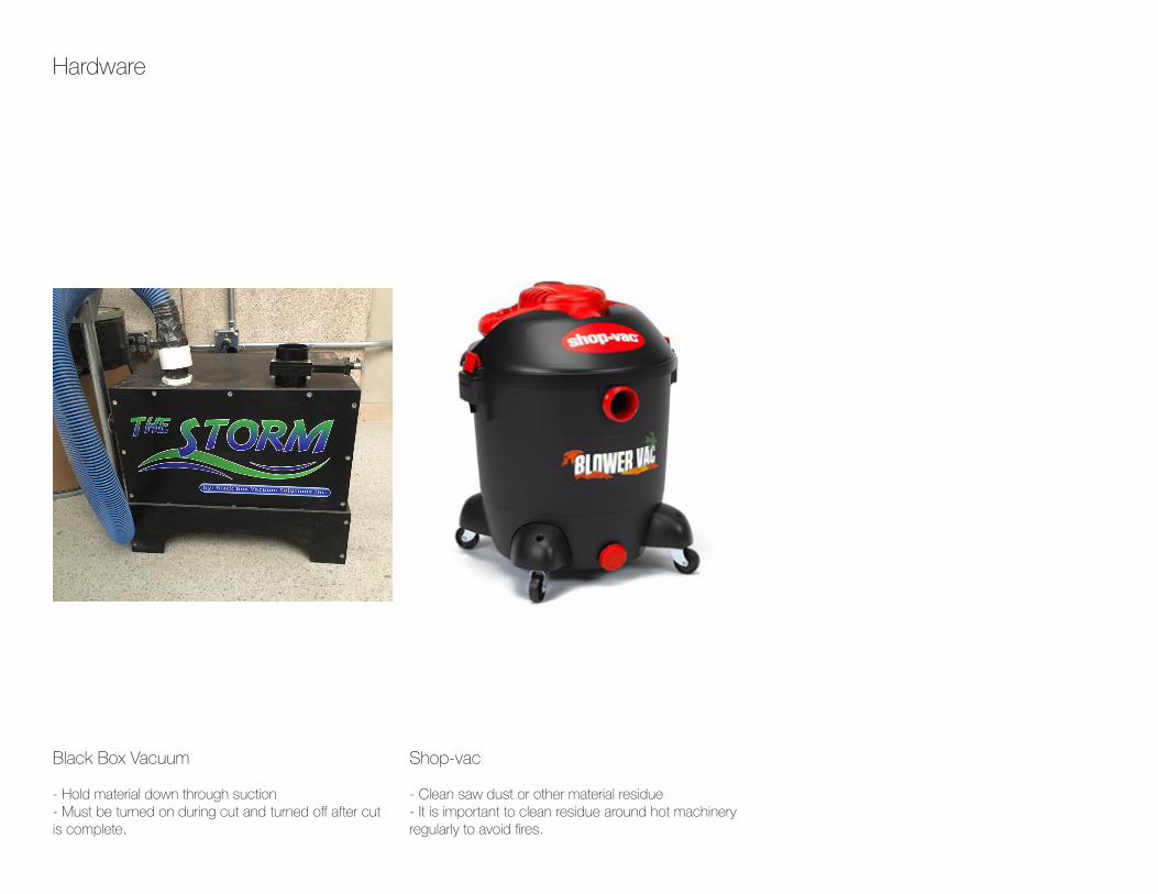
Black Box Vacuum
- Hold material down through suction- Must be turned on during cut and turned off after cut is complete.
Shop-vac
- Clean saw dust or other material residue- It is important to clean residue around hot machinery regularly to avoid fires.
Hardware

3D Mill SetupCut3D Pro- Used to setup the toolpaths for the cut.- For 3D engraving, milling, etc.
CNC SetupCAMaster WinCNC- Used to operate the CNC.
Software
Design Setup
- Rhinoceros, Fusion 360, etc.- A range of software can be used to setup the initial design files to be milled.
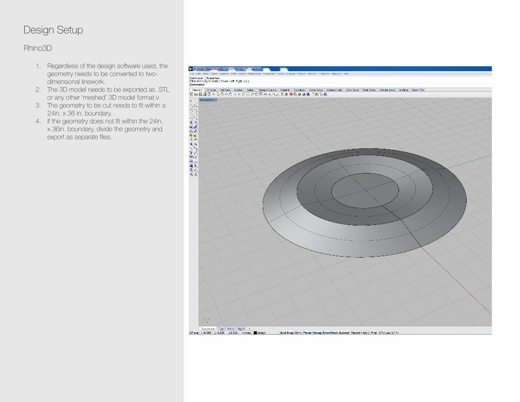
Design SetupRhino3D
1. Regardless of the design software used, the geometry needs to be converted to two-dimensional linework.
2. The 3D model needs to be exported as .STL or any other ‘meshed’ 3D model format.v
3. The geometry to be cut needs to fit within a 24in. x 36 in. boundary.
4. If the geometry does not fit within the 24in. x 36in. boundary, divide the geometry and export as separate files.

3D Mill Setup - Cut3D ProOpening and Job Setup
Open the .STL file.File > (File Location) > (FileName).STLJob Setup
1. Top Surface: Select the appropriate Top Surface. For single sided milling it is most likely ‘Top’.
2. Model Size: Select the appropriate model size (in inches). Check the ‘Lock XYZ ratio’ button to scale proportionally.
3. Units: Inches (unless mm is required)4. Sides to Machine: For single sided milling
select ‘Top”. 5. Click ‘Apply’.6. Click ‘Next’ to continue to next step.
2
3
4
5
6
1

3D Mill Setup - Cut3D ProMaterial Size and Margins
1. Material Size: Length (X): 36 inches Width (Y): 24 inches Thickness (Z): Appropriate thickness of the material.
2. Z Zero: Set Z Zero at the Top of the material.3. Machining Margin around Model: Select the
desired Margin option to carve out the model margin from the material.
4. Depth of Model below Surface: Set appropriate depth of model below the top of the material surface. If starting depth is at the top of the material’s surface the depth needs to be set as 0.0. (Tabs might be added at this point if model is small enough to be displaced during the milling process).
5. Cut Plane Position in Model: Cut Plane position needs to be set at a depth less than total thickness of material. This difference might vary from material to material.
6. Click ‘Apply’. 7. Click ‘Next’ to continue to next step.
2
3
4
5
6
1
7
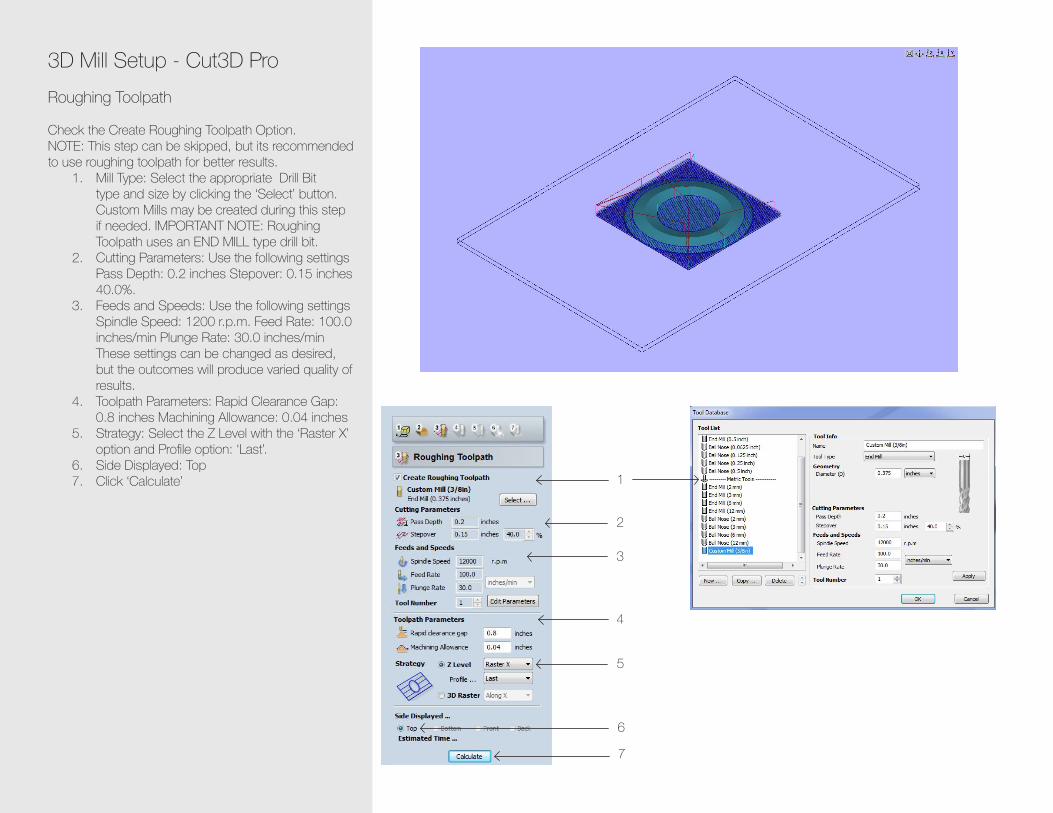
3D Mill Setup - Cut3D ProRoughing Toolpath
Check the Create Roughing Toolpath Option.NOTE: This step can be skipped, but its recommended to use roughing toolpath for better results.
1. Mill Type: Select the appropriate Drill Bit type and size by clicking the ‘Select’ button. Custom Mills may be created during this step if needed. IMPORTANT NOTE: Roughing Toolpath uses an END MILL type drill bit.
2. Cutting Parameters: Use the following settings Pass Depth: 0.2 inches Stepover: 0.15 inches 40.0%.
3. Feeds and Speeds: Use the following settings Spindle Speed: 1200 r.p.m. Feed Rate: 100.0 inches/min Plunge Rate: 30.0 inches/min These settings can be changed as desired, but the outcomes will produce varied quality of results.
4. Toolpath Parameters: Rapid Clearance Gap: 0.8 inches Machining Allowance: 0.04 inches
5. Strategy: Select the Z Level with the ‘Raster X’ option and Profile option: ‘Last’.
6. Side Displayed: Top7. Click ‘Calculate’
2
3
4
5
6
1
7

3D Mill Setup - Cut3D ProFinishing Toolpath
1. Mill Type: Select the appropriate Drill Bit type and size by clicking the ‘Select’ button. Custom Mills may be created during this step if needed. IMPORTANT NOTE: Finishing Toolpath uses a BALL NOSE MILL type drill bit.
2. Cutting Parameters: Use the following settings Stepover: 0.0375 inches - 40.0%.
3. Feeds and Speeds: Use the following settings Spindle Speed: 1200 r.p.m. Feed Rate: 100.0 inches/min Plunge Rate: 30.0 inches/min These settings can be changed as desired, but the outcomes will produce varied quality of results.
4. Toolpath Parameters: Rapid Clearance Gap: 0.8 inches Raster Angle: ‘45 Degrees’
5. Side Displayed: Top6. Click ‘ Calculate’
2
3
4
5
6
1

3D Mill Setup - Cut3D ProCut Out Toolpath
Check the Create Roughing Toolpath Option if the model needs to be cut out from the 24x36 sheet.
1. Mill Type: Select the appropriate Drill Bit type and size by clicking the ‘Select’ button. Custom Mills may be created during this step if needed. IMPORTANT NOTE: Cut Out Toolpath uses an END MILL type drill bit.
2. Cutting Parameters: Use the following settings Pass Depth: 0.2 inches
3. Feeds and Speeds: Use the following settings Spindle Speed: 1200 r.p.m. Feed Rate: 100.0 inches/min Plunge Rate: 30.0 inches/min These settings can be changed as desired, but the outcomes will produce varied quality of results.
4. Toolpath Parameters: Material to Leave: 0.0 inches (unless material needs to be left behind for final product) Profile Cutting Direction: ‘Climb’ Rapid Clearance Gap: 0.8 inches
5. Side Displayed: Top6. Click ‘ Calculate’
23
4
5
1
6

3D Mill Setup - Cut3D ProPreview Machining
Preview each step before saving to ensure the file cuts/mills as desired.
1. Roughing Toolpath Preview2. Finishing Toolpath Preview3. Cut Out Preview4. Reset Preview: To reset the preview5. Select different materials for preview. 6. Side Displayed: Top7. Click ‘Next’ to move to next step
1
7
1
2
3
234
5
6

3D Mill Setup - Cut3D ProSave Toolpaths
Save each toolpath individually.
1. Post Processor: Select ‘WINCNC Inch GCode All Axis (*.txt)’ as the file type.
2. Click on ‘Roughing Toolpath Save...’ to open save menu. Make sure the boxes next to the respective options are checked.
3. Save the file in desired loction as FileName.txt file type (Bottom Image).
4. Repeat above procedure for ‘Finishing Toolpath Save...’ and ‘Cut Out Toolpath Save...’
5. Side in Machine: Top
Files are now ready to be cut. IMPORTANT NOTE: While cutting/milling, it is important to cut the files in the following order
i. Roughing Toolpath fileii. Finishing Toolpath fileiii. Cut Out Toolpath file
1
2
3
5

CNC Setup - CAMaster WinCNCInitial Configurations
1. Once the CNC has been turned on, open the CAMaster WinCNC software.
2. “Initialize” the CNC.3. The “Home” position or the “X0 Y0 Z0”
positions have already been setup. 4. Unless needed keep these settings.5. To change the “X0 Y0” position manually move
the bit by clicking Y “UP” or “DOWN” and X “UP” or “DOWN” keys.
6. Once the bit has been moved to desired location, click “Zero XY”.
7. Similarly the bit height can be adjusted by moving the bit in the Z axis, followed by Zero Z.
8. Once the material has been placed over the CNC Spoil Board, move the bit to any location over the material.
9. Place the “Z Zero Plate” under the bit (Image: Bottom-Left).
10. Click “Touch Top” (This gives the CNC the Start Depth of the material).
11. Once the Touch Top operation is complete, remove Z Zero Plate from the cut area, and close the lift gate.
12. Repeat this process every time the drill bit is changed.

CNC Setup - CAMaster WinCNCOpening the Cut File
1. File > Open > (FileName).txt 2. Start with the Roughing Toolpath file, followed
by the Finishing Toolpath file and finally the Cut Out Toolpath file.
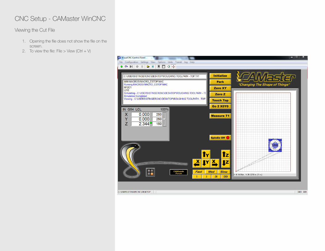
CNC Setup - CAMaster WinCNCViewing the Cut File
1. Opening the file does not show the file on the screen.
2. To view the file: File > View (Ctrl + V)

CNC Setup - CAMaster WinCNCSimulation
1. To simulate the Cut File settings imported from Cut 3D Pro: File > Simulate (Ctrl + S)
2. If all the settings look like the image to the right, the file is ready to be cut.
3. Z Min is the only value that should appear in Red.
4. Click OK.

CNC Setup - CAMaster WinCNCCutting the File
1. After the Simulation is complete, turn the Spindle On.
2. After a slight pause (Once the Spindle is up to speed), the circle under the File menu turns green.
3. Press Enter to start cutting. 4. NOTE: It is important to turn the spindle on before
pressing Enter or else it might ruin the bit.5. In case of emergency, Press the Emergency
STOP button on the CNC or the ESC key on the keyboard.
6. Once the file is cut, turn the Spindle OFF before opening the gates.
7. Repeat these steps for the Finishing Toolpath and Cut Out Toolpath files.


![CNC Milling[1]](https://static.fdocuments.in/doc/165x107/55cf9cd7550346d033ab3f24/cnc-milling1.jpg)