Stepper Drive Box Setup Manual 8-23-04 - FlashCut · PDF file2 - 3.5 Amp Stepper Drive Box...
19
i Control Made Simple 2 - 3.5 Amp Stepper Drive Box Setup Manual © 1998-2004 FlashCut CNC, Inc. West Coast Office 1263 El Camino Real Menlo Park, CA 94025 Phone (650) 853-1444 ♦ Fax (650) 853-1405 www.flashcutcnc.com Midwest Office 444 Lake Cook Road, Suite 17 Deerfield, IL 60015 Phone (847) 940-9305 ♦ Fax (847) 940-9315 www.flashcutcnc.com
Transcript of Stepper Drive Box Setup Manual 8-23-04 - FlashCut · PDF file2 - 3.5 Amp Stepper Drive Box...

i
Control Made Simple
2 - 3.5 Amp Stepper
Drive Box Setup Manual
© 1998-2004 FlashCut CNC, Inc.
West Coast Office 1263 El Camino Real
Menlo Park, CA 94025 Phone (650) 853-1444 ♦ Fax (650) 853-1405
www.flashcutcnc.com
Midwest Office 444 Lake Cook Road, Suite 17
Deerfield, IL 60015 Phone (847) 940-9305 ♦ Fax (847) 940-9315
www.flashcutcnc.com


i
Table of Contents
STEPPER DRIVE BOX CONFIGURATION..........................................................................................................1 SYSTEM HOOK UP DIAGRAM ..............................................................................................................................3 DRIVE SETTINGS .....................................................................................................................................................4
SETTING PHASE CURRENT..........................................................................................................................................4 Current Setting Formula – 2 Amp Half/Full Stepping Drives................................................ 5 Current Setting Table for 2 Amp Drives................................................................................. 6 Current Setting Formula – 3.5 Amp Half/Full Stepping Drives............................................. 6 Current Setting Table for 3.5 Amp Half/Full Stepping Drives............................................... 7 Current Setting Formula – 3.5 Amp Micro Stepping Drives.................................................. 7 Current Setting Table for 3.5 Amp Micro Stepping Drives.................................................... 8
SELECTING BETWEEN FULL AND HALF STEP OPERATION ..........................................................................................8 IDLE CURRENT REDUCTION........................................................................................................................................8 SELF TEST ..................................................................................................................................................................9 MICROSTEP SETTINGS ................................................................................................................................................9
MOTOR SIGNAL SOFTWARE SETTINGS.........................................................................................................10 SIGNAL GENERATOR SETTINGS ......................................................................................................................10
FOR SIGNAL GENERATORS WITH SERIAL NUMBERS BELOW 102000: ......................................................................10 RP4 and RP6......................................................................................................................... 10 U10 and U11......................................................................................................................... 11
FOR SIGNAL GENERATORS WITH SERIAL NUMBERS ABOVE 102000: ........................................................................12 STEPPER MOTOR CABLING...............................................................................................................................12
MOTOR WIRING FOR OTHER STEPPER MOTORS .......................................................................................................13 6 Lead Motor – ½ Coil Bipolar 6 Lead Motor – Series Bipolar........................................ 13 8 Lead Motor – Parallel Bipolar 8 Lead Motor – Series Bipolar....................................... 13 Unknown Motor Wiring ....................................................................................................... 13
DRIVER MODULE UPGRADES ...........................................................................................................................14

1
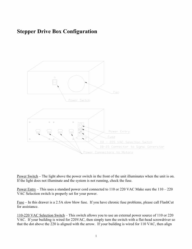
Stepper Drive Box Configuration
Power Switch – The light above the power switch in the front of the unit illuminates when the unit is on. If the light does not illuminate and the system is not running, check the fuse. Power Entry – This uses a standard power cord connected to 110 or 220 VAC Make sure the 110 – 220 VAC Selection switch is properly set for your power. Fuse – In this drawer is a 2.5A slow blow fuse. If you have chronic fuse problems, please call FlashCut for assistance. 110-220 VAC Selection Switch – This switch allows you to use an external power source of 110 or 220 VAC. If your building is wired for 220VAC, then simply turn the switch with a flat-head screwdriver so that the dot above the 220 is aligned with the arrow. If your building is wired for 110 VAC, then align
2
the dot above the 110 with the arrow. Note that severe damage can occur if you have 110 selected and your building is wired for 220VAC.
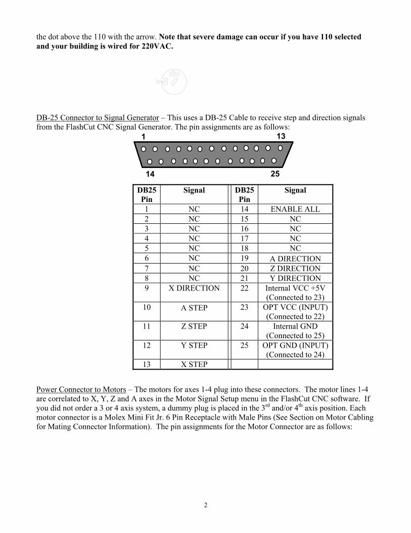
DB-25 Connector to Signal Generator – This uses a DB-25 Cable to receive step and direction signals from the FlashCut CNC Signal Generator. The pin assignments are as follows:
1 13
14 25
DB25 Pin
Signal DB25 Pin
Signal
1 NC 14 ENABLE ALL 2 NC 15 NC 3 NC 16 NC 4 NC 17 NC 5 NC 18 NC 6 NC 19 Α DIRECTION 7 NC 20 Z DIRECTION 8 NC 21 Y DIRECTION 9 X DIRECTION 22 Internal VCC +5V
(Connected to 23) 10 Α STEP 23 OPT VCC (INPUT)
(Connected to 22) 11 Z STEP 24 Internal GND
(Connected to 25) 12 Y STEP 25 OPT GND (INPUT)
(Connected to 24) 13 X STEP
Power Connector to Motors – The motors for axes 1-4 plug into these connectors. The motor lines 1-4 are correlated to X, Y, Z and A axes in the Motor Signal Setup menu in the FlashCut CNC software. If you did not order a 3 or 4 axis system, a dummy plug is placed in the 3rd and/or 4th axis position. Each motor connector is a Molex Mini Fit Jr. 6 Pin Receptacle with Male Pins (See Section on Motor Cabling for Mating Connector Information). The pin assignments for the Motor Connector are as follows:
3
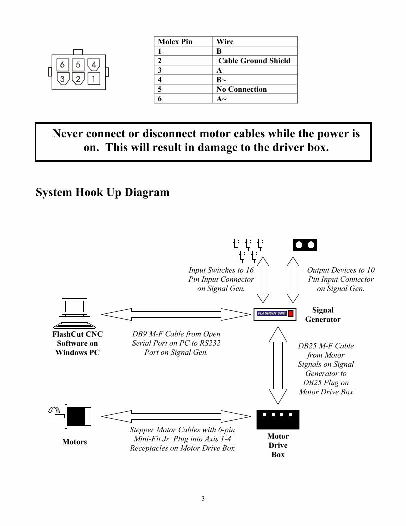
System Hook Up Diagram
Molex Pin Wire 1 B 2 Cable Ground Shield 3 A 4 B~ 5 No Connection 6 A~
Input Switches to 16 Pin Input Connector
on Signal Gen.
Output Devices to 10 Pin Input Connector
on Signal Gen.
Stepper Motor Cables with 6-pin Mini-Fit Jr. Plug into Axis 1-4
Receptacles on Motor Drive Box
DB9 M-F Cable from Open Serial Port on PC to RS232
Port on Signal Gen. DB25 M-F Cable
from Motor Signals on Signal
Generator to DB25 Plug on
Motor Drive Box
Motor Drive Box
Motors
FlashCut CNC Software on Windows PC
Signal Generator
Never connect or disconnect motor cables while the power is on. This will result in damage to the driver box.

4
Drive Settings Inside of the drive box are the individual drive modules for axes 1-4.
Axis 2
Axis 1
Axis 4
Axis 3
Each drive module has Logic Connector for the Step, Direction, COM and Enable signals coming from the Signal generator, a Motor Connector for the A and B Coils of the motor, a Power Connector, and a group of DIP Switches for configuring the drive for your specific requirements. The configuration of the DIP switches vary depending on if you have a 2 amp, 3.5 amp full/half stepping drive, or a 3.5 amp microstepping drive.
Logic Connector
Power Connector
Motor Connec tor
DIP Switches
Dip Switch Settings for the individual motor drives include:
Idle Current Reduction Self Test Mode (Available only in microstepping models) Phase Current Setting (Varies depending on 2 or 3.5 amp systems) Microstep Setting (Available only in microstepping models) Full/Half Step Setting (Available only in full/half stepping models)
Setting Phase Current Before you turn on the power supply the first time, you need to set the driver for the proper motor phase current. The rated current is usually printed on the motor label. The drive current is easy to set. If you

5
wish, you can learn a simple formula for setting current and never need the manual again. Or you can skip to the table on the next page, find the current setting you want, and set the DIP switches according to the picture. Note that the factory current settings for the driver are usually set properly if you purchase both drivers and motors from FlashCut CNC.
Current Setting Formula – 2 Amp Half/Full Stepping Drives Locate the bank of tiny switches near the motor connector. Four of the switches (3, 4, 5 & 6) have a value of current printed next to them. For example, switch 5 has 500 printed next to it. Each switch controls the amount of current, in milliamperes (mA), that it's label indicates. There is always a base of current of 125 mA. To add to that, slide the appropriate switches toward their labels. You may need a small screwdriver for this.
Example Suppose you want to set the driver for 1.625 amps per phase (1625 mA). You need the 125 mA base current plus another 1000 and 500 mA. 1625= 125 + 1000 +500 Slide the 500 and 1000 mA switches (switches 5 & 6) toward the labels as shown in the figure.
HALF STEP
125
250
500
1000

6
Current Setting Table for 2 Amp Drives
.125AMPS/PHASE
CURRENTBASE =125mA
125
250
500
1000
.25AMPS/PHASE
.375AMPS/PHASE
.5AMPS/PHASE
.625AMPS/PHASE
.75AMPS/PHASE
.875AMPS/PHASE
1AMPS/PHASE
1.125AMPS/PHASE
1.25AMPS/PHASE
1.375AMPS/PHASE
1.5AMPS/PHASE
1.625AMPS/PHASE
1.75AMPS/PHASE
1.875AMPS/PHASE
2AMPS/PHASE
CURRENTBASE =125mA
125
250
500
1000
CURRENTBASE =125mA
125
250
500
1000
CURRENTBASE =125mA
125
250
500
1000
CURRENTBASE =125mA
125
250
500
1000
CURRENTBASE =125mA
125
250
500
1000
CURRENTBASE =125mA
125
250
500
1000
CURRENTBASE =125mA
125
250
500
1000
CURRENTBASE =125mA
125
250
500
1000
CURRENTBASE =125mA
125
250
500
1000
CURRENTBASE =125mA
125
250
500
1000
CURRENTBASE =125mA
125
250
500
1000
CURRENTBASE =125mA
125
250
500
1000
CURRENTBASE =125mA
125
250
500
1000
CURRENTBASE =125mA
125
250
500
1000
CURRENTBASE =125mA
125
250
500
1000
Current Setting Formula – 3.5 Amp Half/Full Stepping Drives Locate the bank of tiny switches near the motor connector. Five of the switches (switches 2-6) have a value of current printed next to them. For example, switch 6 has 0.2 printed next to it. Each switch controls the amount of current, in Amps, that it's label indicates. There is always a base of current of 0.4 A. To add to that, slide the appropriate switches toward their labels. You may need a small screwdriver for this.
Example Suppose you want to set the driver for 2.2 amps per phase. You need the 0.4 A base current plus another 1.6 and 0.2 A. 2.2 = 0.4 + 1.6 + 0.2 Slide the 1.6 and 0.2 A switches toward the labels as shown in the figure.
7
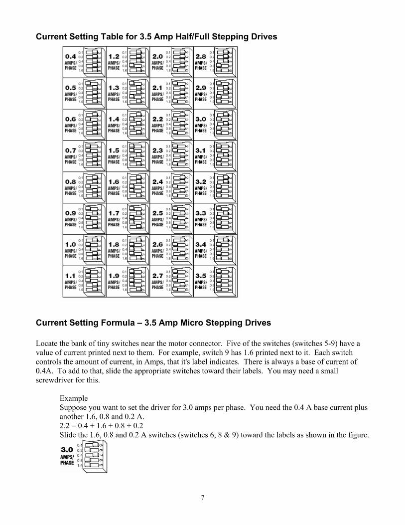
Current Setting Table for 3.5 Amp Half/Full Stepping Drives
Current Setting Formula – 3.5 Amp Micro Stepping Drives Locate the bank of tiny switches near the motor connector. Five of the switches (switches 5-9) have a value of current printed next to them. For example, switch 9 has 1.6 printed next to it. Each switch controls the amount of current, in Amps, that it's label indicates. There is always a base of current of 0.4A. To add to that, slide the appropriate switches toward their labels. You may need a small screwdriver for this.
Example Suppose you want to set the driver for 3.0 amps per phase. You need the 0.4 A base current plus another 1.6, 0.8 and 0.2 A. 2.2 = 0.4 + 1.6 + 0.8 + 0.2 Slide the 1.6, 0.8 and 0.2 A switches (switches 6, 8 & 9) toward the labels as shown in the figure.
8
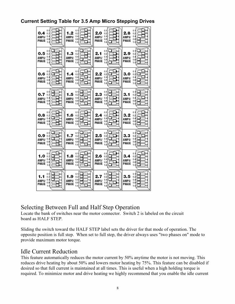
Current Setting Table for 3.5 Amp Micro Stepping Drives
Selecting Between Full and Half Step Operation Locate the bank of switches near the motor connector. Switch 2 is labeled on the circuit board as HALF STEP. Sliding the switch toward the HALF STEP label sets the driver for that mode of operation. The opposite position is full step. When set to full step, the driver always uses "two phases on" mode to provide maximum motor torque. Idle Current Reduction This feature automatically reduces the motor current by 50% anytime the motor is not moving. This reduces drive heating by about 50% and lowers motor heating by 75%. This feature can be disabled if desired so that full current is maintained at all times. This is useful when a high holding torque is required. To minimize motor and drive heating we highly recommend that you enable the idle current

9
reduction feature unless your application strictly forbids it. Idle current reduction is enabled by sliding the switch (Half/Full Stepping Drives – Switch#1, Microstepping Drives – Switch #4) toward the 50% IDLE label, as shown in the sketch below. Sliding the switch away from the 50% IDLE label disables the reduction feature.
Self Test The microstepping drives have a self-test feature. This is used for troubleshooting. If you are unsure about the motor or signal connections to the drive, or if the drive isn't responding to your step pulses, you can turn on the self-test. To activate the self-test, slide switch #1 toward the TEST label. The drive will slowly rotate the motor, 1/2 revolution forward, and then 1/2 rev backward. The pattern repeats until you slide the switch away from the TEST label. The microstepping drive always uses half step mode during the self-test, no matter how you set switches 2 and 3. The self-test ignores the STEP and DIRECTION inputs while operating. The ENABLE input continues to function normally. The Self Test does not test the functionality of the Signal Generator. During normal operation this switch should be off.
Microstep Settings Most step motor drives offer a choice between full step and half step resolutions. In most full step drives, both motor phases are used all the time. Half stepping divides each step into two smaller steps by alternating between both phases on and one phase on. Microstepping drives precisely control the amount of current in each phase at each step position as a means of electronically subdividing the steps even further. The FlashCut CNC Microstepping drive offers a choice of half step and 3 microstep resolutions. The highest setting divides each full step into 64 microsteps, providing 12,800 steps per revolution when using a 1.8° motor. In addition to providing precise positioning and smooth motion, microstep drives can be used to provide motion in convenient units. When the drive is set to 2000 steps/ rev (1/ 10 step) and used with a 5 pitch lead screw, you get .0001 inches/ step. Setting the step resolution is easy. Look at the dip switches on the drive module. Next to switches 2 and 3, there are labels on the printed circuit board. Each switch has two markings on each end. Switch 2 is marked 1/ 5, 1/ 10 at one end and 1/ 5, 1/64 at the other. Switch 3 is labeled 1/ 2, 1/ 5 and 1/ 10, 1/ 64. To set the drive for a resolution, push both switches toward the proper label. For example, if you want 1/ 10 step, push switch 2 toward the 1/ 10 label (to the left) and push switch 3 toward 1/ 10 (on the right). Please refer to the table below and set the switches for the resolution you want.

10
Motor Signal Software Settings The motor settings in the Motor Signal Setup Screen (Shown Below) need to be properly set according to the driver box that you have. The motor settings for your driver box are summarized in the chart below:
Motor Driver Type
2-3.5A Stepper Models 2020, 3020, 4020, 2035, 3035, 4035, 2060, 3060, 4060
2-3.5A Stepper Models that begin with 5000-0XX-1XXXXX or 5000-0XX-2XXXXX
3.5A Micro Stepper Models that begin with 5000-0XX-3XXXXX
8A Micro Stepper
8A and 12A Servo
Step Pulse Polarity Low Low High Low High
Step Pulse Active Edge Trailing Trailing Trailing Leading Trailing
Step Pulse Width 5 10 10 15 15
Enable Signal Polarity Low High High High Low
Dynamic Enable Line Unchecked Unchecked Unchecked Unchecked Unchecked
Signal Generator Settings For Signal Generators With Serial Numbers below 102000:
RP4 and RP6 There are two resistors in the Signal Generator that control the strength of the Step and Direction signals interfacing with the driver box. These two resistors (RP4 and RP6) may need to be removed or changed value for proper use with the driver box. To remove or change these resistors:
1. Remove the two Phillips screws on the bottom of the signal generator. 2. Remove the cover and locate the two 9 pin resistor packs RP4 and RP6. 3. Carefully remove these resistors from their sockets.

11
4. Replace the resistors with the proper value if necessary. Please note that these resistors are not symmetrical. Pin 1 on the resistor is noted with a dot or a line and should coincide with the white square silk screened on the circuit board under the socket.
U10 and U11 Some drivers, such as our microstepping driver need a very fast, sharp signal coming out of the Signal Generator. For these drivers you will need to replace the optical couplers (PS2501-4) in U10 and U11 with a bank 3906 PNP transistors. The wiring diagram of how to do this is shown in the Wiring Diagrams Appendix of the Hardware Guide. The chart below summarizes how RP4, RP6, U10 and U11 need to be configured for each drive.
+
Last Rev.4/22/98
Power
Flashcut CNCSignal GeneratorVersion 2.0.3 Rev. CS.N. ___________
CON1
C15C1
C3
C2
C4U9
C22+
FUSE1SW1
FWB1
TVS1
C25+
FB1
CON3
C20
C24 +
C21
C23+
U15
CR6+
IDC2
U1
C12 C10
U3
C17RP7U16
CR7+
CR8+
CON4
IDC3U13
C16+C14
C9U4U2
C8RP8
CON5
CON2
RP5
U12U14 U17
RP4
C26+
C13
C5C7
U6
IDC1
RP2RP3
RP9
U7
U5
IDC5
CR2+
CR3+
CR4+
CR5+
C18
C19
+
U10 U11
RP6
IDC4
RP1
U8
C6
C11 +R1
OSC1
CR1+

12
Model Number(s) Description RP4 and RP6
U10 and U11
5000-0XX-11XXXX, 5000-0XX-22XXXX,
2 and 3.5 Amp Full/Half Stepping Drive
None PS2501-4 Opto’s
2020, 3020, 4020, 2035, 3035, 4035
2 and 3.5 Amp Full/Half Stepping Drive
470ohm PS2501-4 Opto’s
2070, 3070, 4070, 2120, 3120, 4120
7 and 12 Amp Full/Half Stepping Drive
None PS2501-4 Opto’s
5000-0XX-33XXXX, 3.5 Amp MicroStepping Drive
470ohm 3906 PNP’s
C1-3080, C1-3120 Servo Drive None PS2501-4 Opto’s For Signal Generators with serial numbers above 102000: There is no need to configure the signal strength of the motor signals or output signals. Stepper Motor Cabling Motor Cable - 2 Twisted pair (one pair for A coil and one pair for B Coil) 22 gauge and shielded (18 gauge for 6A motors). Shield is only connected to noted pin on Molex-Waldom connector and should not be connected to motor end. Use Belden - M 8723 CM 2PR22 Shielded Cable or equivalent. Connector - Molex - Waldom 6-Pin Mini-Fit Jr. Receptacle Housing Part # 39-01-2060. Female Pins Part # 39-00-0039 or 39-00-0047
Molex Pin Motor Wire 1 B 2 Cable Ground Shield 3 A 4 B~ 5 No Connection 6 A~
Stepper Motor
13
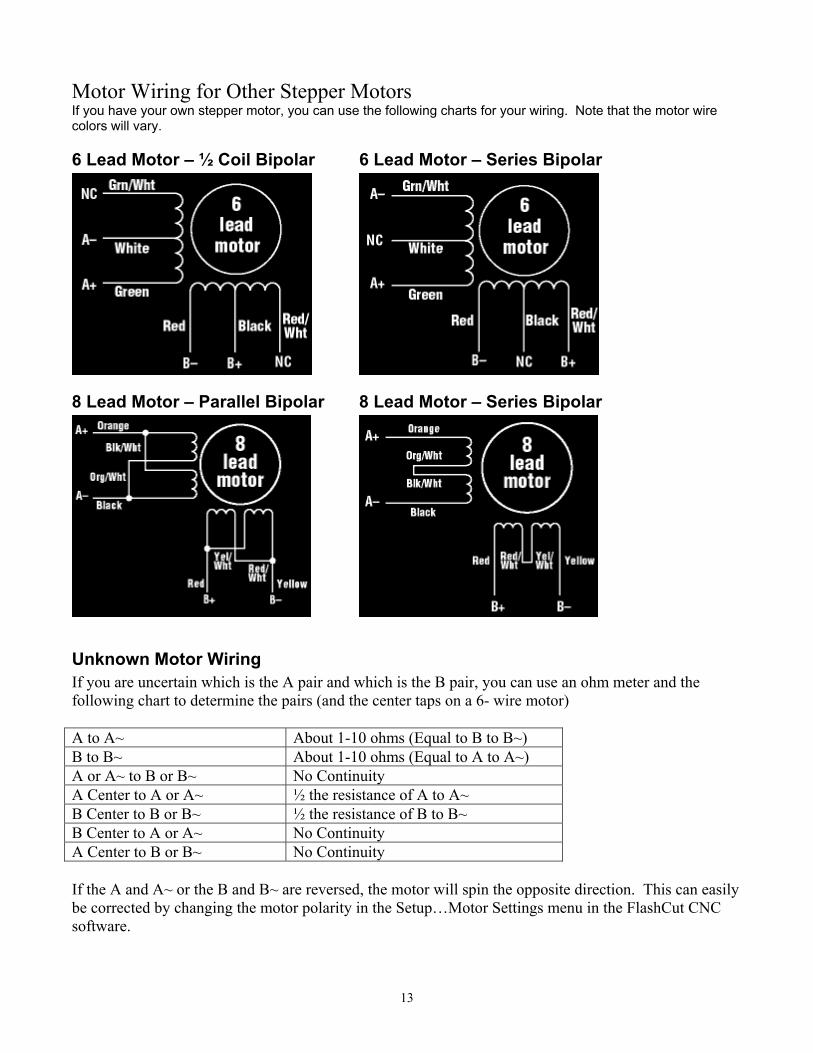
Motor Wiring for Other Stepper Motors If you have your own stepper motor, you can use the following charts for your wiring. Note that the motor wire colors will vary.
6 Lead Motor – ½ Coil Bipolar 6 Lead Motor – Series Bipolar
8 Lead Motor – Parallel Bipolar 8 Lead Motor – Series Bipolar
Unknown Motor Wiring If you are uncertain which is the A pair and which is the B pair, you can use an ohm meter and the following chart to determine the pairs (and the center taps on a 6- wire motor) A to A~ About 1-10 ohms (Equal to B to B~) B to B~ About 1-10 ohms (Equal to A to A~) A or A~ to B or B~ No Continuity A Center to A or A~ ½ the resistance of A to A~ B Center to B or B~ ½ the resistance of B to B~ B Center to A or A~ No Continuity A Center to B or B~ No Continuity If the A and A~ or the B and B~ are reversed, the motor will spin the opposite direction. This can easily be corrected by changing the motor polarity in the Setup…Motor Settings menu in the FlashCut CNC software.

14
Driver Module Upgrades To upgrade your driver box such as adding a 4th axis, or upgrading a drive to microstepping, you should install the new drive module(s) using the following instructions. Improper wiring can cause damage to your driver box and/or motors. Please take care in following these instructions properly.
Direc tionCommon (+ 5V)Step
+ VDC
Enable
-VDC+ A
+ B-B
-A
DIP Switches
Mounting Holes
1. Set the Dip Switches to the appropriate settings for your application.
2. Mount the drive module to the driver box chassis using (2) 4-40 screws, nuts and locking washers.
3. Connect V+ and V- from the power supply to +VDC and –VDC respectively on the power connector on the drive.
4. Connect the wires from the motor receptacle to the drive module motor connector using the following chart. To properly ground your motor cable shield, connect Pin 2 directly to the inside of the chassis. The pins go into the connector with the tabs facing up.
Motor Receptacle
Drive Module Motor Connector
1 B 2 Cable Ground Shield
(to Chassis) 3 A 4 B- 5 No Connection 6 A-
15
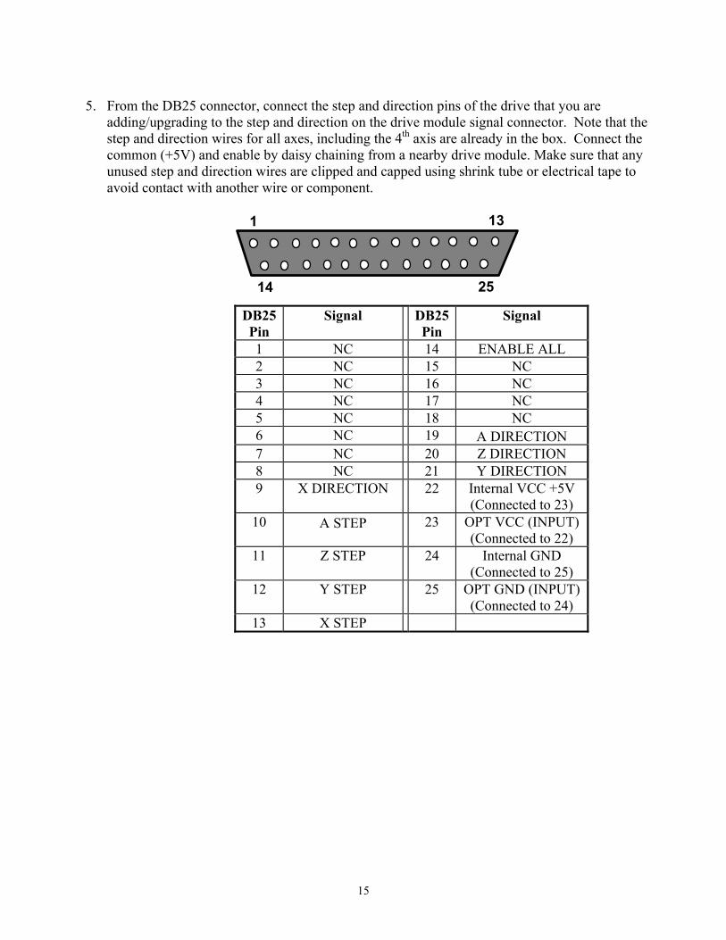
5. From the DB25 connector, connect the step and direction pins of the drive that you are adding/upgrading to the step and direction on the drive module signal connector. Note that the step and direction wires for all axes, including the 4th axis are already in the box. Connect the common (+5V) and enable by daisy chaining from a nearby drive module. Make sure that any unused step and direction wires are clipped and capped using shrink tube or electrical tape to avoid contact with another wire or component.
1 13
14 25
DB25 Pin
Signal DB25 Pin
Signal
1 NC 14 ENABLE ALL 2 NC 15 NC 3 NC 16 NC 4 NC 17 NC 5 NC 18 NC 6 NC 19 Α DIRECTION 7 NC 20 Z DIRECTION 8 NC 21 Y DIRECTION 9 X DIRECTION 22 Internal VCC +5V
(Connected to 23) 10 Α STEP 23 OPT VCC (INPUT)
(Connected to 22) 11 Z STEP 24 Internal GND
(Connected to 25) 12 Y STEP 25 OPT GND (INPUT)
(Connected to 24) 13 X STEP