STEERING - bad-karma.us.com · will determine if the power steering pump or power steering gear is...
20
STEERING TABLE OF CONTENTS page page POWER STEERING ......................... 1 POWER STEERING PUMP ................... 6 RACK & PINION STEERING GEAR ............ 11 STEERING COLUMN ....................... 15 POWER STEERING TABLE OF CONTENTS page page DESCRIPTION AND OPERATION STEERING SYSTEM ....................... 1 DIAGNOSIS AND TESTING POWER STEERING SYSTEM ................ 2 POWER STEERING FLOW AND PRESSURE ..... 4 DESCRIPTION AND OPERATION STEERING SYSTEM DESCRIPTION Power steering systems consist of: • Steering column • Rack and pinion steering gear • Belt driven hydraulic steering pump • Pump pressure and return hoses • Oil Cooler OPERATION The steering column shaft is attached to the gear pinion. The rotation of the pinion moves the gear rack from side-to-side. This lateral action of the rack pushes and pulls the tie rods to change the direction of the front wheels. Power assist is provided by an engine mounted hydraulic pump, (Fig. 1) and (Fig. 2) the pump sup- plies hydraulic fluid pressure to the steering gear. Some vehicles are equipped with an oil cooler. Fig. 1 Steering Pump, Gear And Oil Cooler - 5.2L & 5.9L 1 – HYDRAULIC PUMP 2 – RACK AND PINION GEAR 3 – OIL COOLER DN STEERING 19 - 1
Transcript of STEERING - bad-karma.us.com · will determine if the power steering pump or power steering gear is...
PP
D
D
D
S
D
O
prpo
hpS
DN STEERING 19 - 1
STEERING
TABLE OF CONTENTS
page page
OWER STEERING . . . . . . . . . . . . . . . . . . . . . . . . . 1OWER STEERING PUMP . . . . . . . . . . . . . . . . . . . 6
page
POWER STEERING SYSTEM . . . . . . . . . . . . . . . . 2
RACK & PINION STEERING GEAR . . . . . . . . . . . . 11STEERING COLUMN . . . . . . . . . . . . . . . . . . . . . . . 15
POWER STEERING
TABLE OF CONTENTS
page
ESCRIPTION AND OPERATIONSTEERING SYSTEM . . . . . . . . . . . . . . . . . . . . . . . 1IAGNOSIS AND TESTING
POWER STEERING FLOW AND PRESSURE. . . . . 4
ESCRIPTION AND OPERATION
TEERING SYSTEM
ESCRIPTIONPower steering systems consist of:• Steering column• Rack and pinion steering gear• Belt driven hydraulic steering pump• Pump pressure and return hoses• Oil Cooler
PERATIONThe steering column shaft is attached to the gear
inion. The rotation of the pinion moves the gearack from side-to-side. This lateral action of the rackushes and pulls the tie rods to change the directionf the front wheels.Power assist is provided by an engine mounted
ydraulic pump, (Fig. 1) and (Fig. 2) the pump sup-lies hydraulic fluid pressure to the steering gear.ome vehicles are equipped with an oil cooler.
Fig. 1 Steering Pump, Gear And Oil Cooler - 5.2L &5.9L
1 – HYDRAULIC PUMP2 – RACK AND PINION GEAR3 – OIL COOLER
D
P
stt
19 - 2 STEERING DN
DESCRIPTION AND OPERATION (Continued)
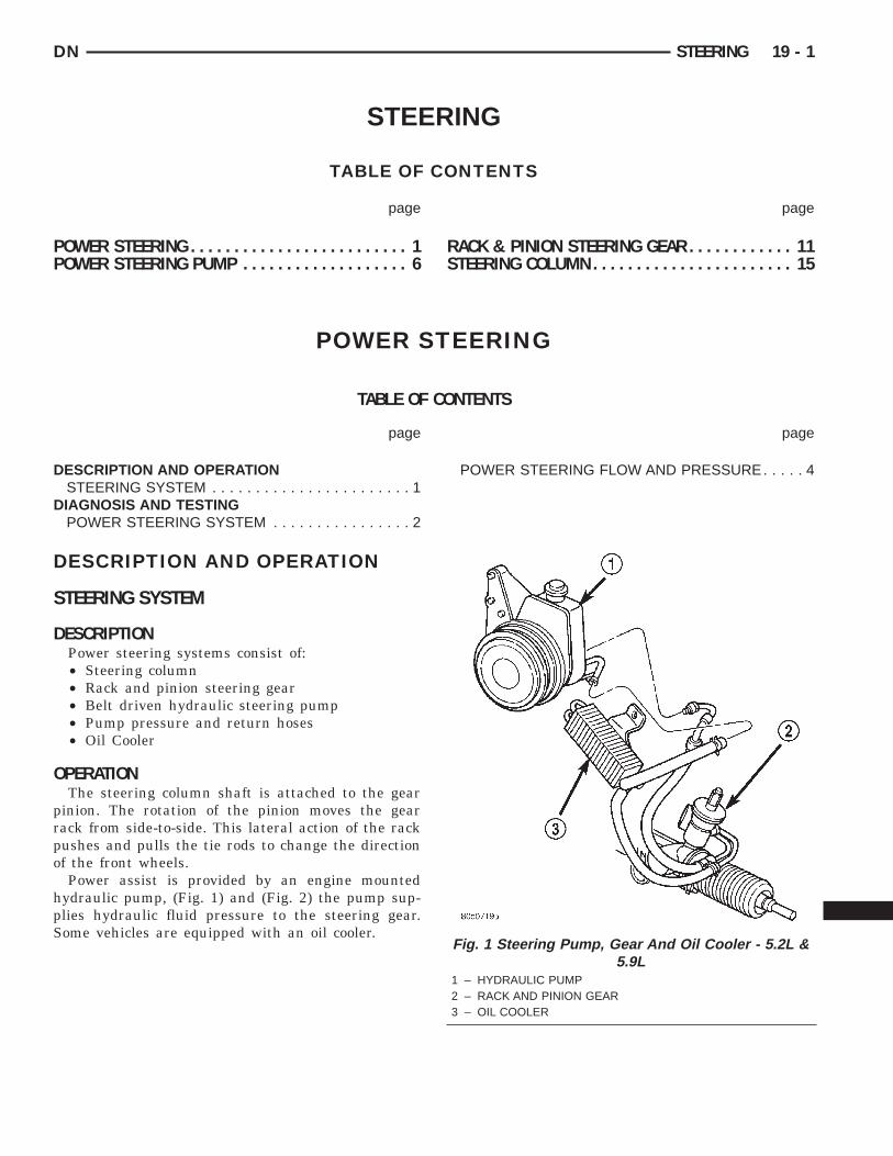
Fig. 2 Steering Pump, Gear And Oil Cooler - 4.7L1 – HYDRAULIC PUMP2 – RACK AND PINION GEAR3 – OIL COOLER
IAGNOSIS AND TESTING
OWER STEERING SYSTEMSTEERING NOISE
There is some noise in all power steering systems. One of the most common is a hissing sound evident at atandstill parking. Or when the steering wheel is at the end of it’s travel. Hiss is a high frequency noise similaro that of a water tap being closed slowly. The noise is present in all valves that have a high velocity fluid passinghrough an orifice. There is no relationship between this noise and steering performance.
CONDITION POSSIBLE CAUSES CORRECTION
OBJECTIONAL HISS ORWHISTLE
1. Steering intermediate shaft to dash panelseal.
1. Check and repair seal at dashpanel.
2. Noisy valve in power steering gear. 2. Replace steering gear.
RATTLE OR CLUNK 1. Gear mounting bolts loose. 1. Tighten bolts to specification.
2. Loose or damaged suspensioncomponents.
2. Inspect and repair suspension.
3. Internal gear noise. 3. Replace steering gear.
4. Pressure hose in contact with othercomponents.
4. Reposition hose.
5. Loose or damaged intermediate shaft orcolumn.
5. Inspect and repair or replace.
CHIRP OR SQUEAL 1. Loose belt. 1. Adjust or replace.

DN STEERING 19 - 3
DIAGNOSIS AND TESTING (Continued)
CONDITION POSSIBLE CAUSES CORRECTION
WHINE OR GROWL 1. Low fluid level. 1. Fill to proper level.
2. Pressure hose in contact with othercomponents.
2. Reposition hose.
3. Internal pump noise. 3. Replace pump.
SUCKING AIR SOUND 1. Loose return line clamp. 1. Replace clamp.
2. O-ring missing or damaged on hosefitting.
2. Replace o-ring.
3. Low fluid level. 3. Fill to proper level.
4. Air leak between pump and reservoir. 4. Repair as necessary.
5. Reservoir cap not installed correctly. 5. Install reservoir cap correctly.
SCRUBBING ORKNOCKING
1. Wrong tire size. 1. Verify tire size.
2. Wrong gear. 2. Verify gear.
BINDING AND STICKING
CONDITION POSSIBLE CAUSE CORRECTION
DIFFICULT TO TURN WHEELSTICKS OR BINDS
1. Low fluid level. 1. Fill to proper level.
2. Tire pressure. 2. Adjust tire pressure.
3. Steering components (balljoints/tie rod ends).
3 Inspect and repair as necessary.
4. Loose belt. 4. Adjust or replace.
5. Low pump pressure. 5. Pressure test and replace ifnecessary.
6. Column shaft coupler binding. 6. Replace coupler.
7. Steering gear worn. 7. Replace gear.
INSUFFICIENT ASST. OR POOR RETURN TO CENTER
CONDITION POSSIBLE CAUSE CORRECTION
HARD TURNING OR MOMENTARYINCREASE IN TURNING EFFORT
1. Tire pressure. 1. Adjust tire pressure.
2. Low fluid level. 2. Fill to proper level.
3. Loose belt. 3. Adjust or replace.
4. Low pump pressure. 4. Pressure test and repair asnecessary.
5. Internal gear leak. 5. Replace gear.
STEERING WHEEL DOES NOTWANT TO RETURN TO CENTERPOSITION
1. Tire pressure. 1. Adjust tire pressure.
2. Wheel alignment. 2. Align front end.
3. Lack of lubrication. 3. Inspect and lubricate suspensioncompnents.
4. High friction in steering gear. 4. Replace gear.
P
ttfmpwsiSA
F
g
S
l
p
s
lge
e
19 - 4 STEERING DN
DIAGNOSIS AND TESTING (Continued)
LOOSE STEERING AND VEHICLE LEAD
CONDITION POSSIBLE CAUSE CORRECTION
EXCESSIVE PLAY IN STEERINGWHEEL
1. Worn or loose suspension orsteering components.
1. Inspect and repair as necessary.
2. Worn or loose wheel bearings. 2. Inspect and repair or adjustbearings.
3. Steering gear mounting. 3. Tighten gear mounting bolts tospecification.
4. Gear out of adjustment. 4. Replace gear.
5. Worn or loose steering coupler. 5. Inspect and replace asnecessary.
VEHICLE PULLS OR LEADS TOONE SIDE.
1. Tire Pressure. 1. Adjust tire pressure.
2. Radial tire lead. 2. Rotate tires.
3. Brakes dragging. 3. Repair as necessary.
4. Wheel alignment. 4. Align front end.
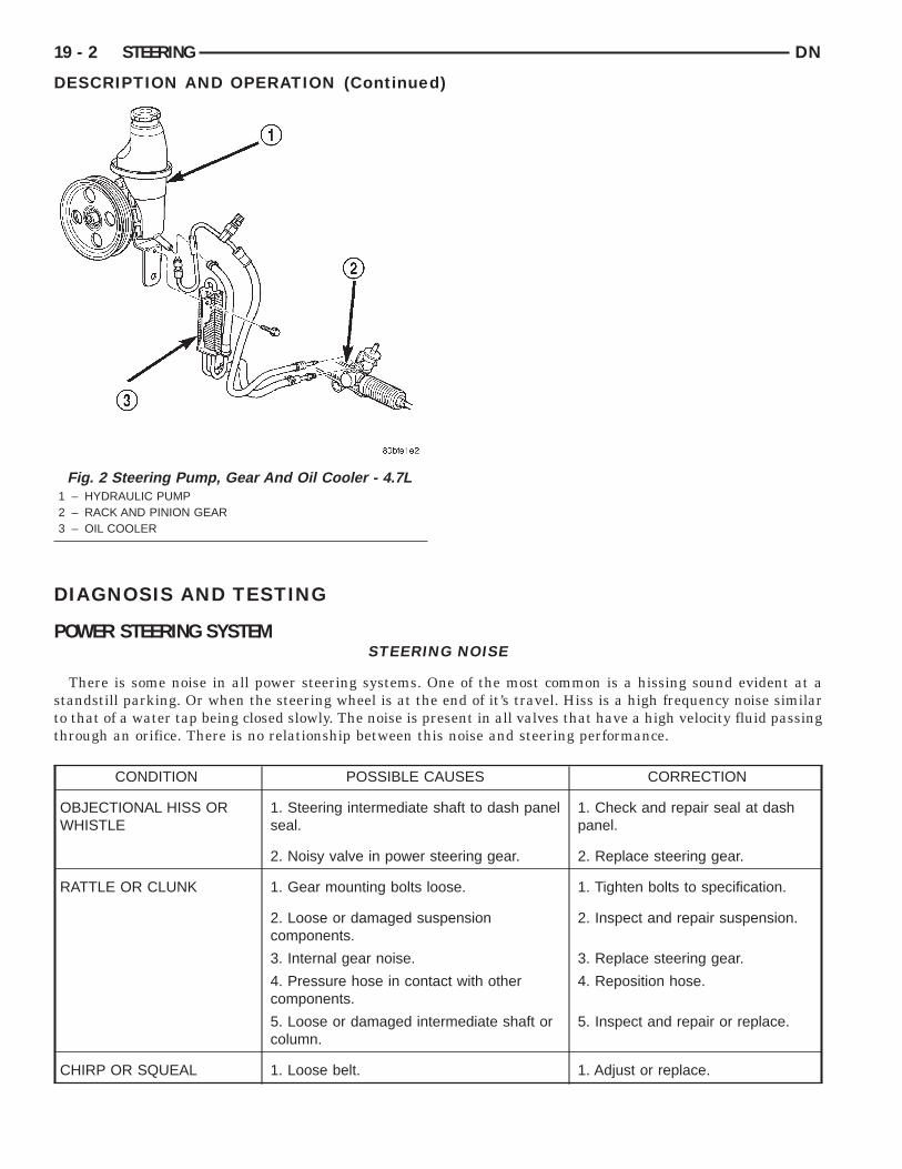
OWER STEERING FLOW AND PRESSUREThe following procedure is used to test the opera-
ion of the power steering system on the vehicle. Thisest will provide the gallons per minute (GPM) orlow rate of the power steering pump along with theaximum relief pressure. Perform test any time a
ower steering system problem is present. This testill determine if the power steering pump or power
teering gear is not functioning properly. The follow-ng pressure and flow test is performed using Powerteering Analyzer Tool kit 6815 (Fig. 3) and (Fig. 4)dapter Kit 6893.
LOW AND PRESSURE TEST(1) Check the power steering belt to ensure it is in
ood condition and adjusted properly.(2) Connect pressure gauge hose from the Power
teering Analyzer to Tube 6844.(3) Connect Adapter 6826 to Power Steering Ana-
yzer test valve end.(4) Disconnect the high pressure hose from the
ower steering pump.(5) Connect the tube to the pump hose fitting.(6) Connect the power steering hose from the
teering gear to the adapter.(7) Open the test valve completely.(8) Start engine and let idle long enough to circu-
ate power steering fluid through flow/pressure testauge and to get air out of the fluid. Then shut offngine.(9) Check fluid level, add fluid as necessary. Start
ngine again and let idle.
(10) Gauge should read below 862 kPa (125 psi), ifabove, inspect the hoses for restrictions and repair asnecessary. The initial pressure reading should be inthe range of 345-552 kPa (50-80 psi).
(11) Increase the engine speed to 1500 RPM andread the flow meter. If the flow rate (GPM) is belowspecification, (refer to pump specification chart forGPM) the pump should be replaced.
Fig. 3 Analyzer With Tube and Adapter For 5.2L &5.9L
1 – GAUGE HOSE2 – TUBE3 – ADAPTER FITTINGS4 – ANALYZER
Ctcfd
DN STEERING 19 - 5
DIAGNOSIS AND TESTING (Continued)
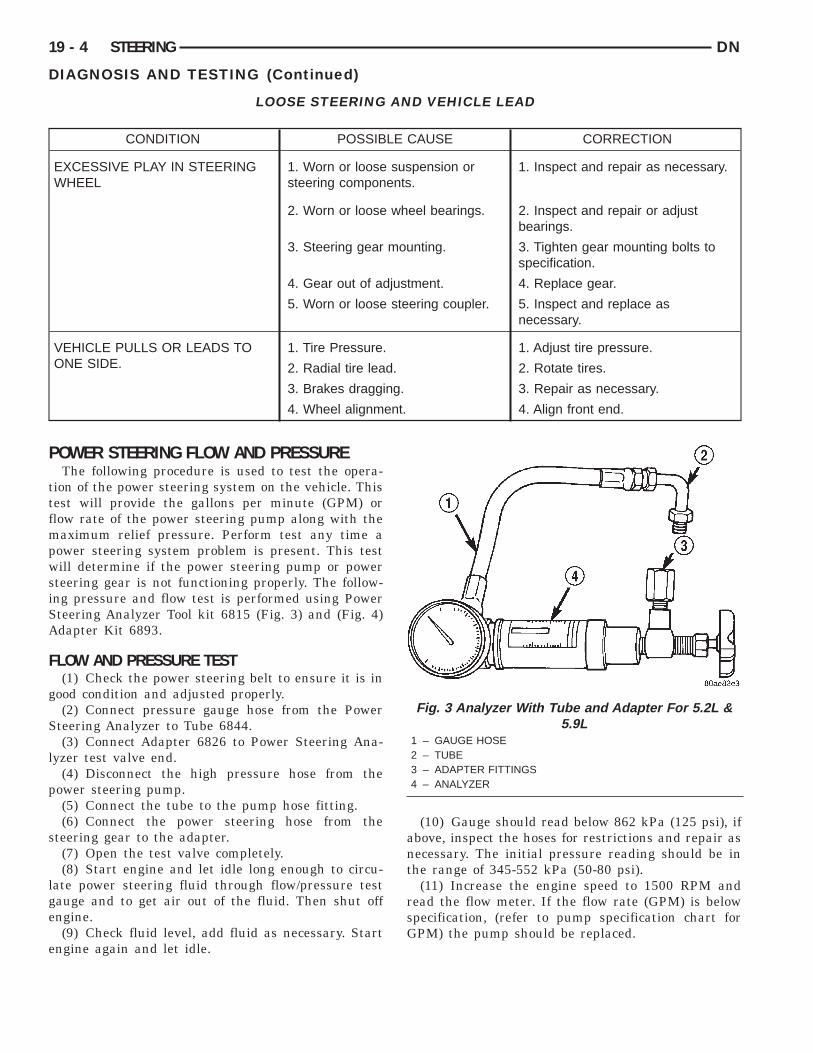
AUTION: The following test procedure involvesesting maximum pump pressure output and flowontrol valve operation. Do not leave valve closedor more than three seconds as the pump could beamaged.
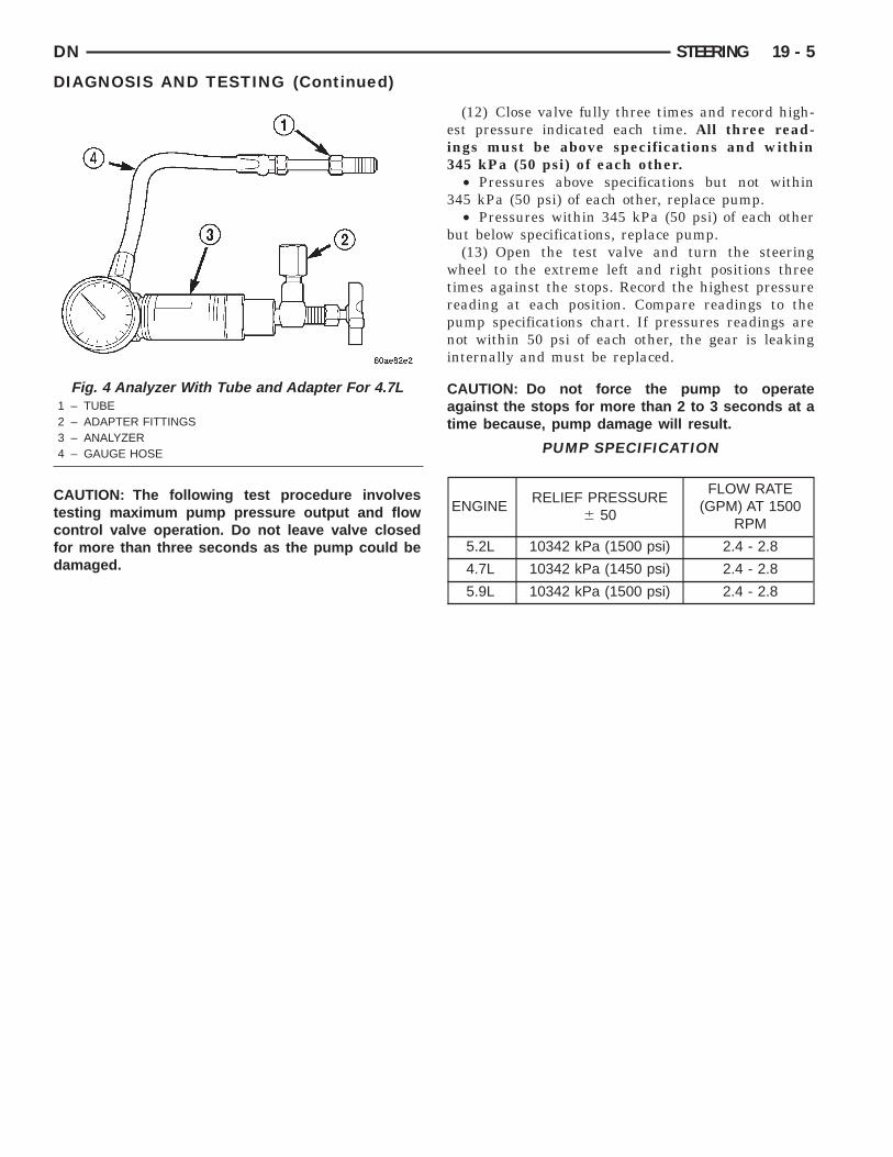
Fig. 4 Analyzer With Tube and Adapter For 4.7L1 – TUBE2 – ADAPTER FITTINGS3 – ANALYZER4 – GAUGE HOSE
(12) Close valve fully three times and record high-est pressure indicated each time. All three read-ings must be above specifications and within345 kPa (50 psi) of each other.
• Pressures above specifications but not within345 kPa (50 psi) of each other, replace pump.
• Pressures within 345 kPa (50 psi) of each otherbut below specifications, replace pump.
(13) Open the test valve and turn the steeringwheel to the extreme left and right positions threetimes against the stops. Record the highest pressurereading at each position. Compare readings to thepump specifications chart. If pressures readings arenot within 50 psi of each other, the gear is leakinginternally and must be replaced.
CAUTION: Do not force the pump to operateagainst the stops for more than 2 to 3 seconds at atime because, pump damage will result.
PUMP SPECIFICATION
ENGINERELIEF PRESSURE
6 50
FLOW RATE(GPM) AT 1500
RPM
5.2L 10342 kPa (1500 psi) 2.4 - 2.8
4.7L 10342 kPa (1450 psi) 2.4 - 2.8
5.9L 10342 kPa (1500 psi) 2.4 - 2.8
D
D
S
R
D
P
D
phc
pt4p
Na
O
i1
19 - 6 STEERING DN
POWER STEERING PUMP
TABLE OF CONTENTS
page page
D
S
S
ESCRIPTION AND OPERATIONPOWER STEERING PUMP . . . . . . . . . . . . . . . . . . 6IAGNOSIS AND TESTINGPUMP LEAKAGE . . . . . . . . . . . . . . . . . . . . . . . . . . 7ERVICE PROCEDURESPOWER STEERING PUMP - INITIAL
OPERATION . . . . . . . . . . . . . . . . . . . . . . . . . . . . 7EMOVAL AND INSTALLATION
POWER STEERING PUMP - 5.2L & 5.9L . . . . . . . . 7) and (Fig. 2). The power steering pumps are con-
POWER STEERING PUMP - 4.7L. . . . . . . . . . . . . . 8ISASSEMBLY AND ASSEMBLYPUMP PULLEY . . . . . . . . . . . . . . . . . . . . . . . . . . . 9PECIFICATIONSTORQUE CHART . . . . . . . . . . . . . . . . . . . . . . . . . . 9PECIAL TOOLSPOWER STEERING PUMP . . . . . . . . . . . . . . . . . . 9
ESCRIPTION AND OPERATION
OWER STEERING PUMP
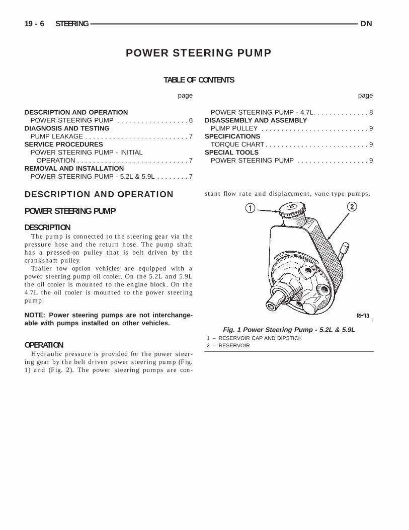
ESCRIPTIONThe pump is connected to the steering gear via the
ressure hose and the return hose. The pump shaftas a pressed-on pulley that is belt driven by therankshaft pulley.Trailer tow option vehicles are equipped with a
ower steering pump oil cooler. On the 5.2L and 5.9Lhe oil cooler is mounted to the engine block. On the.7L the oil cooler is mounted to the power steeringump.
OTE: Power steering pumps are not interchange-ble with pumps installed on other vehicles.
PERATIONHydraulic pressure is provided for the power steer-
ng gear by the belt driven power steering pump (Fig.
stant flow rate and displacement, vane-type pumps.
Fig. 1 Power Steering Pump - 5.2L & 5.9L1 – RESERVOIR CAP AND DIPSTICK2 – RESERVOIR
D
P
nr
S
PO
WCF
Cea
DN STEERING 19 - 7
DESCRIPTION AND OPERATION (Continued)
IAGNOSIS AND TESTING
UMP LEAKAGEThe pump is serviced as an assembly and should
ot be disassembled. Plastic pump reservoirs can beeplace and the reservoir O-ring.Check for leaks in the following areas:• Pump shaft seal behind the pulley• Pump to reservoir O-ring• Reservoir cap• Pressure and return lines• Flow control valve fitting
ERVICE PROCEDURES
OWER STEERING PUMP - INITIALPERATION
ARNING: THE FLUID LEVEL SHOULD BEHECKED WITH ENGINE OFF TO PREVENT INJURYROM MOVING COMPONENTS.
AUTION: Use MOPAR Power Steering Fluid orquivalent. Do not use automatic transmission fluidnd do not overfill.
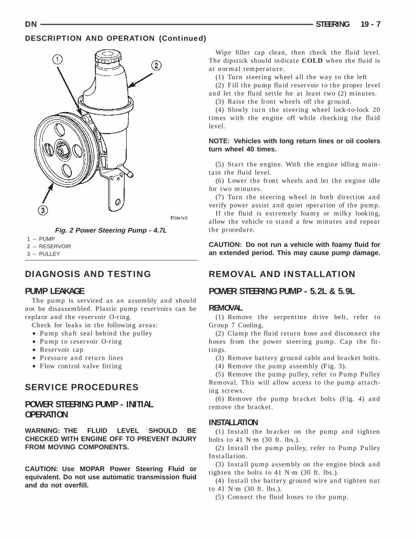
Fig. 2 Power Steering Pump - 4.7L1 – PUMP2 – RESERVOIR3 – PULLEY
Wipe filler cap clean, then check the fluid level.The dipstick should indicate COLD when the fluid isat normal temperature.
(1) Turn steering wheel all the way to the left(2) Fill the pump fluid reservoir to the proper level
and let the fluid settle for at least two (2) minutes.(3) Raise the front wheels off the ground.(4) Slowly turn the steering wheel lock-to-lock 20
times with the engine off while checking the fluidlevel.
NOTE: Vehicles with long return lines or oil coolersturn wheel 40 times.
(5) Start the engine. With the engine idling main-tain the fluid level.
(6) Lower the front wheels and let the engine idlefor two minutes.
(7) Turn the steering wheel in both direction andverify power assist and quiet operation of the pump.
If the fluid is extremely foamy or milky looking,allow the vehicle to stand a few minutes and repeatthe procedure.
CAUTION: Do not run a vehicle with foamy fluid foran extended period. This may cause pump damage.
REMOVAL AND INSTALLATION
POWER STEERING PUMP - 5.2L & 5.9L
REMOVAL(1) Remove the serpentine drive belt, refer to
Group 7 Cooling.(2) Clamp the fluid return hose and disconnect the
hoses from the power steering pump. Cap the fit-tings.
(3) Remove battery ground cable and bracket bolts.(4) Remove the pump assembly (Fig. 3).(5) Remove the pump pulley, refer to Pump Pulley
Removal. This will allow access to the pump attach-ing screws.
(6) Remove the pump bracket bolts (Fig. 4) andremove the bracket.
INSTALLATION(1) Install the bracket on the pump and tighten
bolts to 41 N·m (30 ft. lbs.).(2) Install the pump pulley, refer to Pump Pulley
Installation.(3) Install pump assembly on the engine block and
tighten the bolts to 41 N·m (30 ft. lbs.).(4) Install the battery ground wire and tighten nut
to 41 N·m (30 ft. lbs.).(5) Connect the fluid hoses to the pump.
7
r
19 - 8 STEERING DN
REMOVAL AND INSTALLATION (Continued)
(6) Install the serpentine drive belt refer to GroupCooling.(7) Fill the reservoir with power steering fluid,
efer to Power Steering Pump Initial–Operation.
Fig. 3 Pump Assembly1 – PUMP ASSEMBLY2 – BOLTS
Fig. 4 Pump Mounting Bracket1 – PULLEY2 – PUMP BRACKET3 – STEERING PUMP4 – BOLT
POWER STEERING PUMP - 4.7L
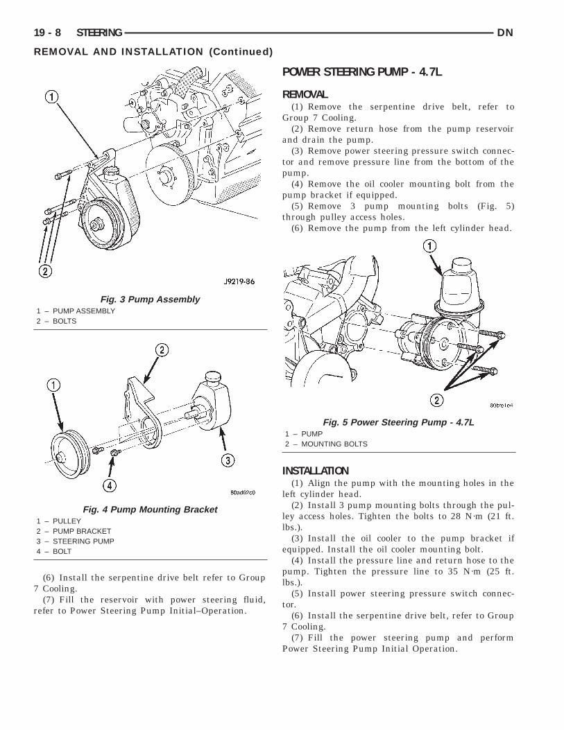
REMOVAL(1) Remove the serpentine drive belt, refer to
Group 7 Cooling.(2) Remove return hose from the pump reservoir
and drain the pump.(3) Remove power steering pressure switch connec-
tor and remove pressure line from the bottom of thepump.
(4) Remove the oil cooler mounting bolt from thepump bracket if equipped.
(5) Remove 3 pump mounting bolts (Fig. 5)through pulley access holes.
(6) Remove the pump from the left cylinder head.
INSTALLATION(1) Align the pump with the mounting holes in the
left cylinder head.(2) Install 3 pump mounting bolts through the pul-
ley access holes. Tighten the bolts to 28 N·m (21 ft.lbs.).
(3) Install the oil cooler to the pump bracket ifequipped. Install the oil cooler mounting bolt.
(4) Install the pressure line and return hose to thepump. Tighten the pressure line to 35 N·m (25 ft.lbs.).
(5) Install power steering pressure switch connec-tor.
(6) Install the serpentine drive belt, refer to Group7 Cooling.
(7) Fill the power steering pump and performPower Steering Pump Initial Operation.
Fig. 5 Power Steering Pump - 4.7L1 – PUMP2 – MOUNTING BOLTS
D
P
D
(
A
(t
DN STEERING 19 - 9
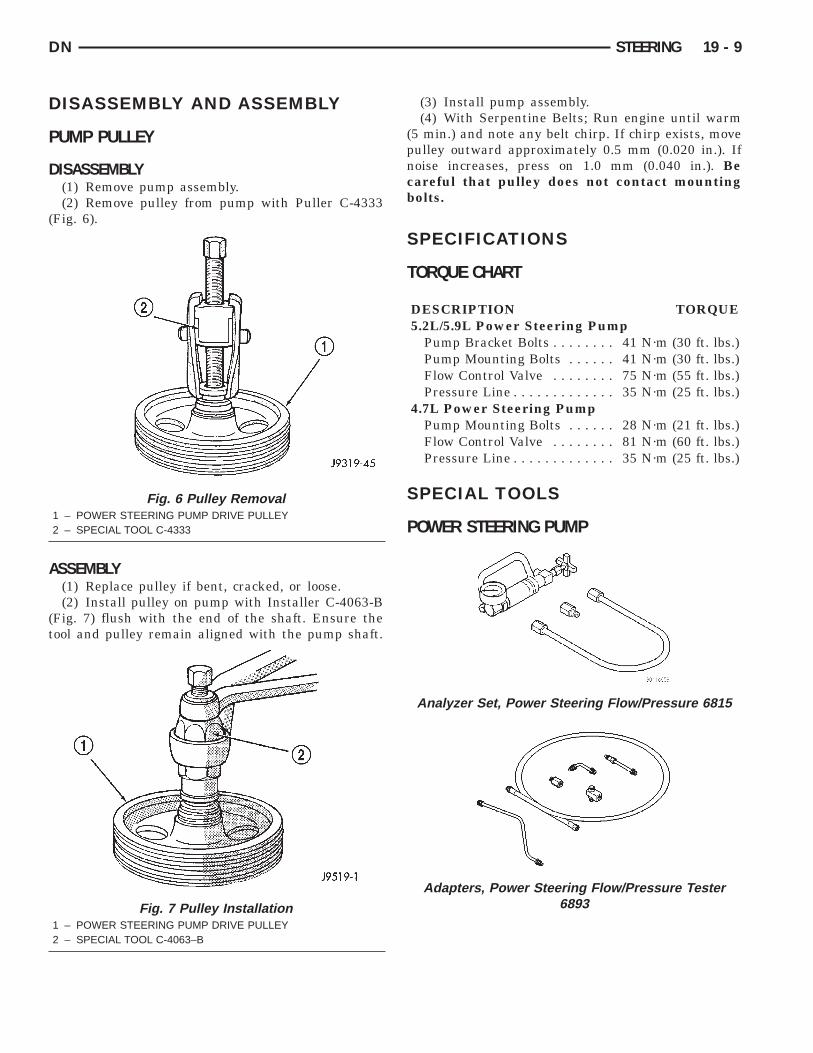
ISASSEMBLY AND ASSEMBLY
UMP PULLEY
ISASSEMBLY(1) Remove pump assembly.(2) Remove pulley from pump with Puller C-4333
Fig. 6).
SSEMBLY(1) Replace pulley if bent, cracked, or loose.(2) Install pulley on pump with Installer C-4063-B
Fig. 7) flush with the end of the shaft. Ensure theool and pulley remain aligned with the pump shaft.
Fig. 6 Pulley Removal1 – POWER STEERING PUMP DRIVE PULLEY2 – SPECIAL TOOL C-4333
Fig. 7 Pulley Installation1 – POWER STEERING PUMP DRIVE PULLEY2 – SPECIAL TOOL C-4063–B
(3) Install pump assembly.(4) With Serpentine Belts; Run engine until warm
(5 min.) and note any belt chirp. If chirp exists, movepulley outward approximately 0.5 mm (0.020 in.). Ifnoise increases, press on 1.0 mm (0.040 in.). Becareful that pulley does not contact mountingbolts.
SPECIFICATIONS
TORQUE CHART
DESCRIPTION TORQUE5.2L/5.9L Power Steering Pump
Pump Bracket Bolts . . . . . . . . 41 N·m (30 ft. lbs.)Pump Mounting Bolts . . . . . . 41 N·m (30 ft. lbs.)Flow Control Valve . . . . . . . . 75 N·m (55 ft. lbs.)Pressure Line . . . . . . . . . . . . . 35 N·m (25 ft. lbs.)
4.7L Power Steering PumpPump Mounting Bolts . . . . . . 28 N·m (21 ft. lbs.)Flow Control Valve . . . . . . . . 81 N·m (60 ft. lbs.)Pressure Line . . . . . . . . . . . . . 35 N·m (25 ft. lbs.)
SPECIAL TOOLS
POWER STEERING PUMP
Analyzer Set, Power Steering Flow/Pressure 6815
Adapters, Power Steering Flow/Pressure Tester6893
19 - 10 STEERING DN
SPECIAL TOOLS (Continued)
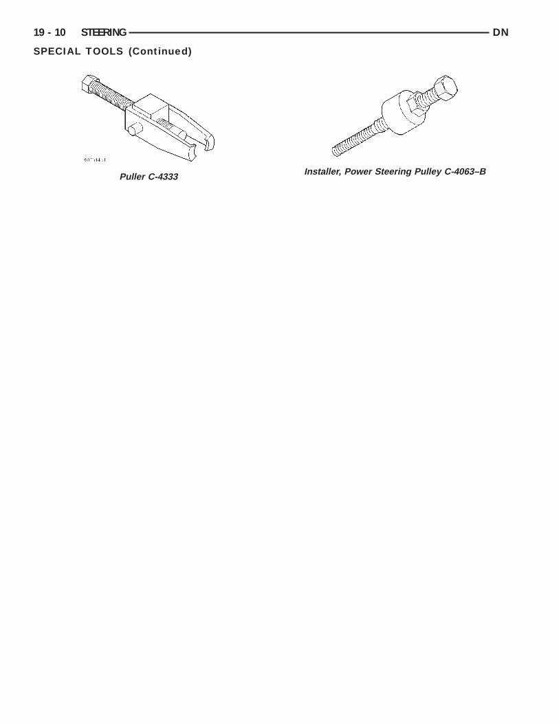
Puller C-4333
Installer, Power Steering Pulley C-4063–B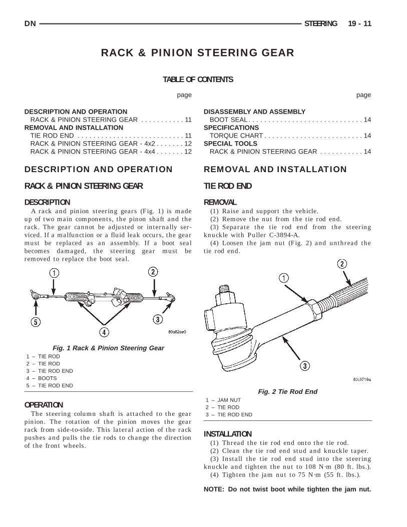
D
R
D
R
D
urvmbr
O
prpo
DN STEERING 19 - 11
RACK & PINION STEERING GEAR
TABLE OF CONTENTS
page page
D
S
S
ESCRIPTION AND OPERATIONRACK & PINION STEERING GEAR . . . . . . . . . . . 11EMOVAL AND INSTALLATIONTIE ROD END . . . . . . . . . . . . . . . . . . . . . . . . . . . 11RACK & PINION STEERING GEAR - 4x2 . . . . . . . 12
RACK & PINION STEERING GEAR - 4x4 . . . . . . . 12ISASSEMBLY AND ASSEMBLYBOOT SEAL. . . . . . . . . . . . . . . . . . . . . . . . . . . . . 14PECIFICATIONSTORQUE CHART . . . . . . . . . . . . . . . . . . . . . . . . . 14PECIAL TOOLS
RACK & PINION STEERING GEAR . . . . . . . . . . . 14ESCRIPTION AND OPERATION
ACK & PINION STEERING GEAR
ESCRIPTIONA rack and pinion steering gears (Fig. 1) is made
p of two main components, the pinon shaft and theack. The gear cannot be adjusted or internally ser-iced. If a malfunction or a fluid leak occurs, the gearust be replaced as an assembly. If a boot seal
ecomes damaged, the steering gear must beemoved to replace the boot seal.
PERATIONThe steering column shaft is attached to the gear
inion. The rotation of the pinion moves the gearack from side-to-side. This lateral action of the rackushes and pulls the tie rods to change the directionf the front wheels.
Fig. 1 Rack & Pinion Steering Gear1 – TIE ROD2 – TIE ROD3 – TIE ROD END4 – BOOTS5 – TIE ROD END
REMOVAL AND INSTALLATION
TIE ROD END
REMOVAL(1) Raise and support the vehicle.(2) Remove the nut from the tie rod end.(3) Separate the tie rod end from the steering
knuckle with Puller C-3894-A.(4) Loosen the jam nut (Fig. 2) and unthread the
tie rod end.
INSTALLATION(1) Thread the tie rod end onto the tie rod.(2) Clean the tie rod end stud and knuckle taper.(3) Install the tie rod end stud into the steering
knuckle and tighten the nut to 108 N·m (80 ft. lbs.).(4) Tighten the jam nut to 75 N·m (55 ft. lbs.).
NOTE: Do not twist boot while tighten the jam nut.
Fig. 2 Tie Rod End1 – JAM NUT2 – TIE ROD3 – TIE ROD END

S
R
R
P
c
t
I
Nr
m
a
19 - 12 STEERING DN
REMOVAL AND INSTALLATION (Continued)
(5) Remove support and lower vehicle.(6) Adjust the wheel toe position, Refer to Group 2
uspension.
ACK & PINION STEERING GEAR - 4x2
EMOVAL(1) Raise and support the vehicle.(2) Remove the nuts from the tie rod ends.(3) Separate tie rod ends from the knuckles with
uller C-3894-A (Fig. 3).
(4) Remove the power steering lines from the gear.(5) Remove the lower coupler bolt and slide the
oupler off the gear (Fig. 4).(6) Remove the mounting bolts from the gear to
he front crossmember and remove the gear (Fig. 5).
NSTALLATION
OTE: Before installing gear inspect bushings andeplace if worn or damaged.
(1) Install gear on front crossmember and tightenounting bolts to 258 N·m (190 ft. lbs.).(2) Slide shaft coupler onto gear. Install new bolt
nd tighten to 49 N·m (36 ft. lbs.).(3) Clean tie rod end studs and knuckle tapers.
Fig. 3 Tie Rod End Puller1 – TOOL C-3894-A2 – BALL STUD3 – SEAL4 – TIE-ROD END5 – LOCKNUT
(4) Install tie rod ends into the steering knucklesand tighten the nuts to 108 N·m (80 ft. lbs.).
(5) Install power steering lines to steering gear.(6) Remove support and lower vehicle.(7) Fill system with fluid and perform Power
Steering Pump Initial Operation.(8) Adjust the toe position. Refer to Group 2 Sus-
pension.
RACK & PINION STEERING GEAR - 4x4
REMOVAL(1) Raise and support the vehicle.
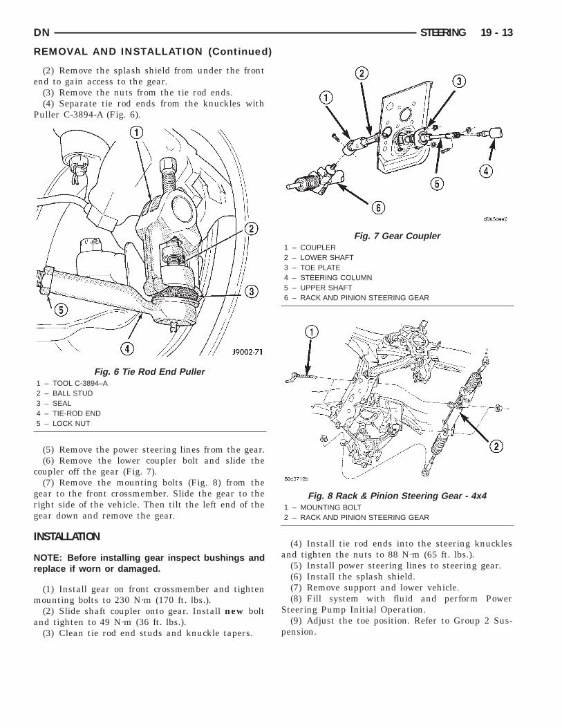
Fig. 4 Gear Coupler1 – COUPLER2 – LOWER SHAFT3 – TOE PLATE4 – STEERING COLUMN5 – UPPER SHAFT6 – RACK AND PINION STEERING GEAR
Fig. 5 Rack & Pinion Steering Gear - 4x21 – RACK AND PINION STEERING GEAR2 – BUSHING
e
P
c
grg
I
Nr
m
a
DN STEERING 19 - 13
REMOVAL AND INSTALLATION (Continued)
(2) Remove the splash shield from under the frontnd to gain access to the gear.(3) Remove the nuts from the tie rod ends.(4) Separate tie rod ends from the knuckles with
uller C-3894-A (Fig. 6).
(5) Remove the power steering lines from the gear.(6) Remove the lower coupler bolt and slide the
oupler off the gear (Fig. 7).(7) Remove the mounting bolts (Fig. 8) from the
ear to the front crossmember. Slide the gear to theight side of the vehicle. Then tilt the left end of theear down and remove the gear.
NSTALLATION
OTE: Before installing gear inspect bushings andeplace if worn or damaged.
(1) Install gear on front crossmember and tightenounting bolts to 230 N·m (170 ft. lbs.).(2) Slide shaft coupler onto gear. Install new bolt
nd tighten to 49 N·m (36 ft. lbs.).(3) Clean tie rod end studs and knuckle tapers.
Fig. 6 Tie Rod End Puller1 – TOOL C-3894–A2 – BALL STUD3 – SEAL4 – TIE-ROD END5 – LOCK NUT
(4) Install tie rod ends into the steering knucklesand tighten the nuts to 88 N·m (65 ft. lbs.).
(5) Install power steering lines to steering gear.(6) Install the splash shield.(7) Remove support and lower vehicle.(8) Fill system with fluid and perform Power
Steering Pump Initial Operation.(9) Adjust the toe position. Refer to Group 2 Sus-
pension.
Fig. 7 Gear Coupler1 – COUPLER2 – LOWER SHAFT3 – TOE PLATE4 – STEERING COLUMN5 – UPPER SHAFT6 – RACK AND PINION STEERING GEAR
Fig. 8 Rack & Pinion Steering Gear - 4x41 – MOUNTING BOLT2 – RACK AND PINION STEERING GEAR

D
B
R
e
(
t(
19 - 14 STEERING DN
ISASSEMBLY AND ASSEMBLY
OOT SEAL
EMOVAL(1) Remove steering gear.(2) Loosen the jam nut then remove the tie rod
nd and jam nut.(3) Remove the outer clamp from the rubber boot
Fig. 9).(4) Remove the boot inner clamp.(5) On 4x2 vehicles mark the breather tube loca-
ion on steering gear before removing the rubber bootFig. 9).
Fig. 9 Boot Seal - 4x21 – CIRCLE “A”2 – MARK BREATHER TUBE LOCATION3 – BOOT4 – SNORKEL CLAMP5 – BOOT CLAMP (OUTER)6 – JAM NUT7 – USE LUBE HERE8 – BOOT CLAMP (INNER)9 – BOOT SEAL10 – BREATHER TUBE11 – BREATHER TUBE
INSTALLATION(1) Lubricate the boot outer groove (tie rod) with
silicone type lubricant. Ensure that the boot is nottwisted.
(2) On 4x2 vehicles align the breather tube withthe reference mark on the steering gear.
(3) Position and align the new boot over the hous-ing.
(4) Install inner clamp on the rubber boot.(5) Install the snorkel clamp on 4x2 vehicles.(6) Install outer clamp on the inner tie rod.(7) Install the jam nut and the tie rod end.(8) Install steering gear.
SPECIFICATIONS
TORQUE CHART
DESCRIPTION TORQUERack and Pinion Steering Gear
Gear to Frame Bolts . . . . . . 258 N·m (190 ft. lbs.)Intermediate Shaft Bolt . . . . . 49 N·m (36 ft. lbs.)
Tie Rod EndKnuckle Nut . . . . . . . . . . . . 108 N·m (80 ft. lbs.)Jam Nut . . . . . . . . . . . . . . . . 75 N·m (55 ft. lbs.)
LinesPressure Line . . . . . . . . . . . . . 35 N·m (25 ft. lbs.)Return Line . . . . . . . . . . . . . . 35 N·m (25 ft. lbs.)
SPECIAL TOOLS
RACK & PINION STEERING GEAR
Puller C-3894-A
D
D
R
D
S
dsci
S
w
rC
WCATF
DN STEERING 19 - 15
STEERING COLUMN
TABLE OF CONTENTS
page page
S
ESCRIPTION AND OPERATIONSTEERING COLUMN . . . . . . . . . . . . . . . . . . . . . . 15IAGNOSIS AND TESTINGIGNITION SWITCH. . . . . . . . . . . . . . . . . . . . . . . . 15EMOVAL AND INSTALLATION STEERING COLUMN . . . . . . . . . . . . . . . . . . . . . . 16GEAR SHIFT LEVER . . . . . . . . . . . . . . . . . . . . . . 18PECIFICATIONSTORQUE CHART . . . . . . . . . . . . . . . . . . . . . . . . . 19
ESCRIPTION AND OPERATION
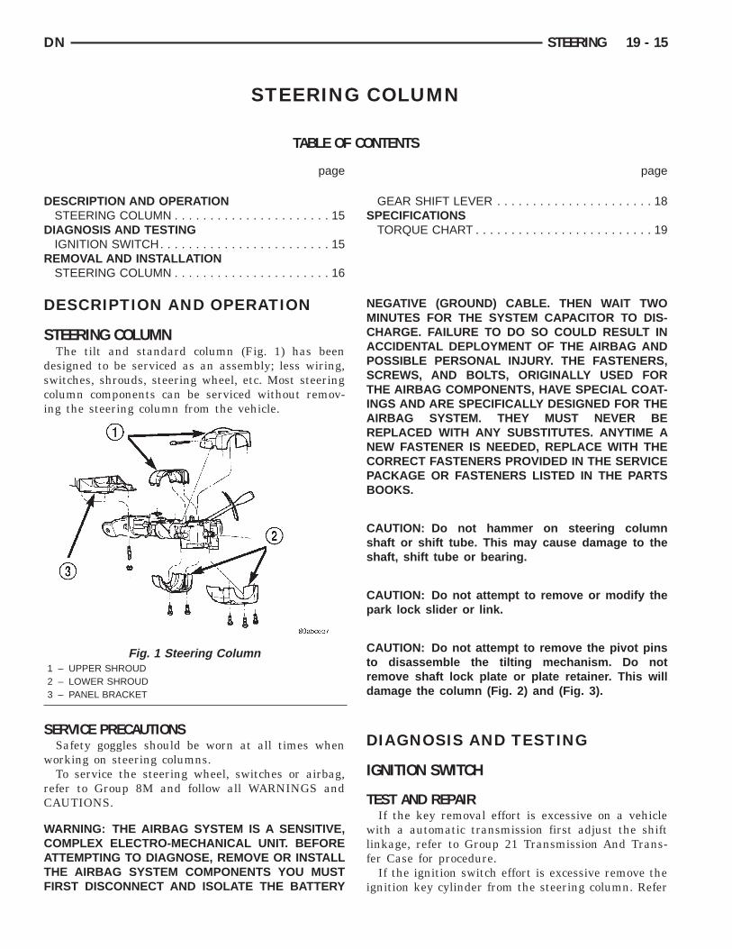
TEERING COLUMNThe tilt and standard column (Fig. 1) has been
esigned to be serviced as an assembly; less wiring,witches, shrouds, steering wheel, etc. Most steeringolumn components can be serviced without remov-ng the steering column from the vehicle.
ERVICE PRECAUTIONSSafety goggles should be worn at all times whenorking on steering columns.To service the steering wheel, switches or airbag,
efer to Group 8M and follow all WARNINGS andAUTIONS.
ARNING: THE AIRBAG SYSTEM IS A SENSITIVE,OMPLEX ELECTRO-MECHANICAL UNIT. BEFORETTEMPTING TO DIAGNOSE, REMOVE OR INSTALLHE AIRBAG SYSTEM COMPONENTS YOU MUSTIRST DISCONNECT AND ISOLATE THE BATTERY
Fig. 1 Steering Column1 – UPPER SHROUD2 – LOWER SHROUD3 – PANEL BRACKET
NEGATIVE (GROUND) CABLE. THEN WAIT TWOMINUTES FOR THE SYSTEM CAPACITOR TO DIS-CHARGE. FAILURE TO DO SO COULD RESULT INACCIDENTAL DEPLOYMENT OF THE AIRBAG ANDPOSSIBLE PERSONAL INJURY. THE FASTENERS,SCREWS, AND BOLTS, ORIGINALLY USED FORTHE AIRBAG COMPONENTS, HAVE SPECIAL COAT-INGS AND ARE SPECIFICALLY DESIGNED FOR THEAIRBAG SYSTEM. THEY MUST NEVER BEREPLACED WITH ANY SUBSTITUTES. ANYTIME ANEW FASTENER IS NEEDED, REPLACE WITH THECORRECT FASTENERS PROVIDED IN THE SERVICEPACKAGE OR FASTENERS LISTED IN THE PARTSBOOKS.
CAUTION: Do not hammer on steering columnshaft or shift tube. This may cause damage to theshaft, shift tube or bearing.
CAUTION: Do not attempt to remove or modify thepark lock slider or link.
CAUTION: Do not attempt to remove the pivot pinsto disassemble the tilting mechanism. Do notremove shaft lock plate or plate retainer. This willdamage the column (Fig. 2) and (Fig. 3).
DIAGNOSIS AND TESTING
IGNITION SWITCH
TEST AND REPAIRIf the key removal effort is excessive on a vehicle
with a automatic transmission first adjust the shiftlinkage, refer to Group 21 Transmission And Trans-fer Case for procedure.
If the ignition switch effort is excessive remove theignition key cylinder from the steering column. Refer
teeif
a
a
R
S
WCAT
19 - 16 STEERING DN
DIAGNOSIS AND TESTING (Continued)
o Group 8D Ignition System. Check the turningffort of the key cylinder. If the ignition key cylinderffort is excessive replace the key cylinder. If thegnition key cylinder operates properly look for theollowing conditions.
(1) Look for rough areas or flash in the castingnd if found remove with a file (Fig. 4).(2) Grease the lock plate actuator, lock plate, slider
nd locking link.
EMOVAL AND INSTALLATION
TEERING COLUMN
ARNING: BEFORE SERVICING THE STEERINGOLUMN THE AIRBAG SYSTEM MUST BE DIS-RMED, REFER TO GROUP 8M RESTRAINT SYS-EMS FOR SERVICE PROCEDURES. FAILURE TO
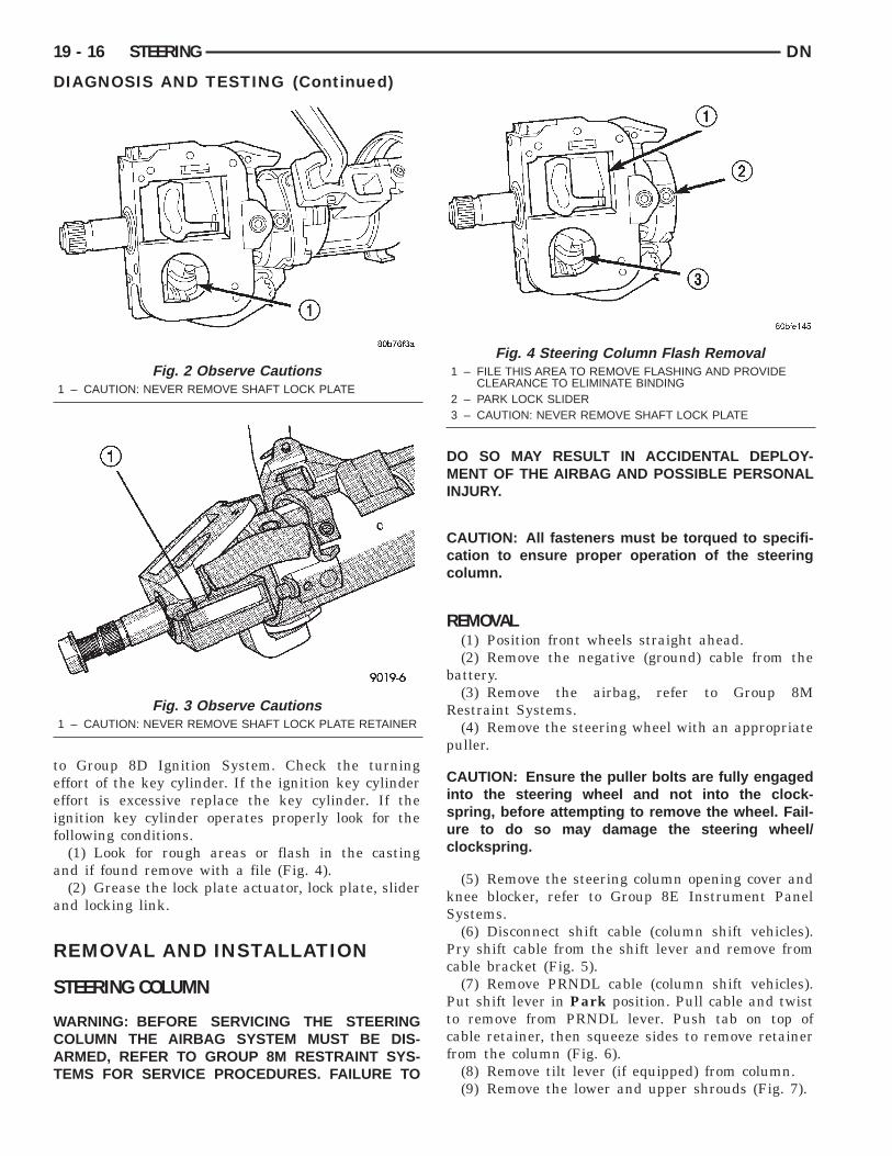
Fig. 2 Observe Cautions1 – CAUTION: NEVER REMOVE SHAFT LOCK PLATE
Fig. 3 Observe Cautions1 – CAUTION: NEVER REMOVE SHAFT LOCK PLATE RETAINER
DO SO MAY RESULT IN ACCIDENTAL DEPLOY-MENT OF THE AIRBAG AND POSSIBLE PERSONALINJURY.
CAUTION: All fasteners must be torqued to specifi-cation to ensure proper operation of the steeringcolumn.
REMOVAL(1) Position front wheels straight ahead.(2) Remove the negative (ground) cable from the
battery.(3) Remove the airbag, refer to Group 8M
Restraint Systems.(4) Remove the steering wheel with an appropriate
puller.
CAUTION: Ensure the puller bolts are fully engagedinto the steering wheel and not into the clock-spring, before attempting to remove the wheel. Fail-ure to do so may damage the steering wheel/clockspring.
(5) Remove the steering column opening cover andknee blocker, refer to Group 8E Instrument PanelSystems.
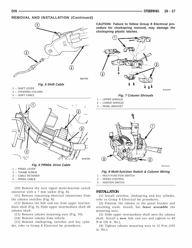
(6) Disconnect shift cable (column shift vehicles).Pry shift cable from the shift lever and remove fromcable bracket (Fig. 5).
(7) Remove PRNDL cable (column shift vehicles).Put shift lever in Park position. Pull cable and twistto remove from PRNDL lever. Push tab on top ofcable retainer, then squeeze sides to remove retainerfrom the column (Fig. 6).
(8) Remove tilt lever (if equipped) from column.
Fig. 4 Steering Column Flash Removal1 – FILE THIS AREA TO REMOVE FLASHING AND PROVIDE
CLEARANCE TO ELIMINATE BINDING2 – PARK LOCK SLIDER3 – CAUTION: NEVER REMOVE SHAFT LOCK PLATE
(9) Remove the lower and upper shrouds (Fig. 7).
c
t
dc
d
DN STEERING 19 - 17
REMOVAL AND INSTALLATION (Continued)
(10) Remove the turn signal multi-function switchonnector with a 7 mm socket (Fig. 8).(11) Remove remaining electrical connections from
he column switches (Fig. 8).(12) Remove the bolt and nut from upper interme-
iate shaft (Fig. 9). Slide upper intermediate shaft offolumn shaft.(13) Remove column mounting nuts (Fig. 10).(14) Remove column from vehicle.(15) Remove clockspring, switches and key cylin-
er, refer to Group 8 Electrical for procedures.
Fig. 5 Shift Cable1 – SHIFT LEVER2 – STEERING COLUMN3 – SHIFT CABLE
Fig. 6 PRNDL Drive Cable1 – PRNDL LEVER2 – THUMB SCREW3 – CABLE RETAINER4 – PRNDL CABLE
CAUTION: Failure to follow Group 8 Electrical pro-cedure for clockspring removal, may damage theclockspring plastic latches.
INSTALLATION(1) Install switches, clockspring and key cylinder,
refer to Group 8 Electrical for procedures.(2) Position the column to the panel bracket and
attaching studs. Install, but loose assemble themounting nuts.
(3) Slide upper intermediate shaft onto the columnshaft. Install a new bolt and nut and tighten to 49N·m (36 ft. lbs.).
(4) Tighten column mounting nuts to 12 N·m (105in. lbs.).
Fig. 7 Column Shrouds1 – UPPER SHROUD2 – LOWER SHROUD3 – PANEL BRACKET
Fig. 8 Multi-function Switch & Column Wiring1 – MULTI-FUNCTION SWITCH2 – SPEED CONTROL3 – IGNITION SWITCH

t
s
19 - 18 STEERING DN
REMOVAL AND INSTALLATION (Continued)
(5) Connect the multi-function switch wiring andighten with 7mm socket to 2 N·m (17 in. lbs.).
(6) Install the wiring connections to the columnwitches.
Fig. 9 Column Shafts & Couplers1 – COUPLER2 – LOWER SHAFT3 – TOE PLATE4 – STEERING COLUMN5 – UPPER SHAFT6 – RACK AND PINION STEERING GEAR
Fig. 10 Column Mounting Nuts1 – MOUNTING NUTS
(7) Install the lower and upper shrouds.(8) Install the PRNDL cable (column shift vehi-
cles). Place shifter in Park position. If indicator needsadjusting turn thumb screw on cable retainer toadjust cable.
(9) Install shift cable (column shift vehicles).(10) Install the tilt lever (if equipped).(11) Install the knee blocker and steering column
opening cover, refer to Group 8E Instrument PanelSystems for procedures.
(12) Install steering wheel and tighten nut to 47N·m (35 ft. lbs.).
(13) Install airbag, refer to Group 8M RestraintSystems for procedure.
(14) Connect the battery ground (negative) cable.(15) Check operation of the automatic transmis-
sion shift linkage and adjust as necessary. Refer toGroup 21, Transmission and Transfer Case foradjustment procedure.
GEAR SHIFT LEVER
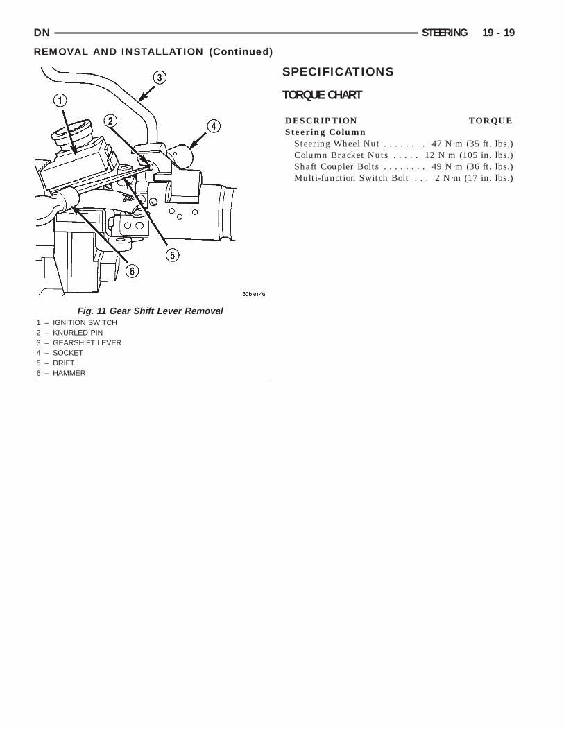
REMOVAL(1) Support the steering column assembly as
shown in (Fig. 11) using a suitable size socket andback-up support.
(2) Disconnect over drive switch wiring.(3) Using a drift of the appropriate size drive the
knurled pin out of the steering column and gear shiftlever. Remove the gear shift lever from the steeringcolumn assembly.
CAUTION: The pin can only be removed from thedirection shown (Fig. 11).
INSTALLATION(1) Support the steering column using a suitable
size socket and back-up support.(2) Install the gear shift lever into the steering col-
umn assembly. Align the pin holes in the gear shiftlever and the steering column assembly.
CAUTION: The pin must be installed in the originaldirection.
(3) Carefully Install the pin into the steering col-umn assembly and through the shift lever. If the pinbinds check the alignment on the holes. Be sure pinis fully installed into the steering column assembly.
(4) Connect over drive switch wiring.
DN STEERING 19 - 19
REMOVAL AND INSTALLATION (Continued)
SPECIFICATIONS
TORQUE CHART
DESCRIPTION TORQUESteering Column
Steering Wheel Nut . . . . . . . . 47 N·m (35 ft. lbs.)Column Bracket Nuts . . . . . 12 N·m (105 in. lbs.)Shaft Coupler Bolts . . . . . . . . 49 N·m (36 ft. lbs.)Multi-function Switch Bolt . . . 2 N·m (17 in. lbs.)
Fig. 11 Gear Shift Lever Removal1 – IGNITION SWITCH2 – KNURLED PIN3 – GEARSHIFT LEVER4 – SOCKET5 – DRIFT6 – HAMMER