STEEL BRIDGE CONSTRUCTION - Minnesota … · for delivery of the fabricated parts to the bridge...
22
November 1, 2005 BRIDGE CONSTRUCTION MANUAL 5-393.400 STEEL BRIDGE CONSTRUCTION 5-393.400 5-393.401 GENERAL This section deals primarily with field inspection procedures relative to structural steel, but applies also to other structural metals which may be required for completion of a structure. Information is included which applies to shop fabrication, so field inspectors will have some knowledge of work that has been done prior to delivery of these materials to the job site. In addition to structural members, such miscellaneous items as drains, ice breakers, bearing assemblies, metal railings and posts, name plates, protection angles, etc. should also be included within the scope of steel construction. 5-393.402 FABRICATION Fabrication of structural metals consists of the operations necessary to prepare members or groups of members for use in structures. It includes the procuring of the required materials prior to shop operations, actual shop operations, and loading for delivery of the fabricated parts to the bridge site. Fabrication should be in accordance with approved shop detail drawings; and, generally, all structural metal materials will be inspected under the supervision of the Structural Metals Engineer (Bridge Office). 5-393.403 SHOP DETAIL DRAWINGS As specified in Specification 2471 , the Contractor shall furnish shop detail drawings for the complete fabrication of all structural metals required by the Contract. These drawings, when approved by the Fabrication Methods Engineer, become part of the Contract and work must be done in accordance with them. Shop drawings should show all pertinent dimensions and details, together with any other information required during fabrication and erection, including types of connections, types, sizes and lengths of welds, bolt sizes and lists. Also included is a match marking diagram which shows the correct positioning of the various members which are not interchangeable and which should be followed explicitly in order that the best possible “make-up” of sections will be obtained. Each sheet of the shop detail drawings should be examined for the Fabrication Methods Engineer’s approval. Changes and corrections are frequently made on shop drawings, and these sometimes change construction requirements or pay quantities. Shop detail drawings should be checked before work is done that could be affected by these drawings; for example, railing shop detail drawings should be checked before concrete is placed which secures cast-in-place anchorages for the railposts. The Fabrication Methods Engineer should be consulted regarding questions pertaining to shop detail drawings which cannot be resolved in the field. 5-393.404 STRUCTURAL METALS SHOP INSPECTION A policy has been adopted for handling inspection and inspection reports which result in documented assurance that all metal parts of a structure have been inspected and approved. The following instructions apply only to those metal materials which are to be inspected by the Bridge Office, Structural Metals Inspection Unit. They do not apply to materials for which sampling and inspection is by manufacturer’s certification or performed by project personnel. The Engineer, who has been assigned the project, should promptly remind the Contractor (by letter or during the pre- construction conference) that information relative to the source of materials should be forwarded to him or her within the allotted time. Upon receipt of information from the Contractor of the source of materials, copies should be sent by the Project Engineer to the Materials Engineer and to the Structural Metals Engineer. It is very important that this information be forwarded as quickly as possible after the contract has been awarded, if the procedure outlined within this manual is to function effectively. When the Structural Metals Engineer has been notified by the Project Engineer of the source of the various metal parts, the Structural Metals Engineer will assume responsibility for their inspection. The Metals Quality Inspectors, after having completed shop inspection of the unit or assembly, will attach a shipping tag directly to the shipper’s documents. The Site Inspector should verify that no material has been shipped in addition to what is listed on the tag. Two types of tags are currently used as shown in Figures A and B 5-393.404 . The smaller tag, Figure A is typically used when all shop activities (fabrication, blasting, coating) are done at one location. The larger tag, Figure B is typically used when these activities are done at more than one location. If the Inspector’s signature is on the tag, all activities have been inspected. If an item happens to be shipped to the job site before all shop activities are inspected, the Inspector’s initials will not be in all the activity boxes and their signature will not be on the tag. If the Inspector’s signature is not on the tag, or if material is received without a tag, the material should not be incorporated into the work. In this case, the site Inspector should call the Structural Metals Inspection Unit to discuss how inspection will be accomplished. Whenever possible, the Structural Metals Inspection Unit will notify the Project Engineer that material is being shipped to the job site without final shop inspection.
Transcript of STEEL BRIDGE CONSTRUCTION - Minnesota … · for delivery of the fabricated parts to the bridge...

November 1, 2005 BRIDGE CONSTRUCTION MANUAL 5-393.400
STEEL BRIDGE CONSTRUCTION 5-393.400
5-393.401 GENERAL This section deals primarily with field inspection procedures relative to structural steel, but applies also to other structural metals which may be required for completion of a structure. Information is included which applies to shop fabrication, so field inspectors will have some knowledge of work that has been done prior to delivery of these materials to the job site. In addition to structural members, such miscellaneous items as drains, ice breakers, bearing assemblies, metal railings and posts, name plates, protection angles, etc. should also be included within the scope of steel construction. 5-393.402 FABRICATION Fabrication of structural metals consists of the operations necessary to prepare members or groups of members for use in structures. It includes the procuring of the required materials prior to shop operations, actual shop operations, and loading for delivery of the fabricated parts to the bridge site. Fabrication should be in accordance with approved shop detail drawings; and, generally, all structural metal materials will be inspected under the supervision of the Structural Metals Engineer (Bridge Office). 5-393.403 SHOP DETAIL DRAWINGS As specified in Specification 2471, the Contractor shall furnish shop detail drawings for the complete fabrication of all structural metals required by the Contract. These drawings, when approved by the Fabrication Methods Engineer, become part of the Contract and work must be done in accordance with them. Shop drawings should show all pertinent dimensions and details, together with any other information required during fabrication and erection, including types of connections, types, sizes and lengths of welds, bolt sizes and lists. Also included is a match marking diagram which shows the correct positioning of the various members which are not interchangeable and which should be followed explicitly in order that the best possible “make-up” of sections will be obtained. Each sheet of the shop detail drawings should be examined for the Fabrication Methods Engineer’s approval. Changes and corrections are frequently made on shop drawings, and these sometimes change construction requirements or pay quantities. Shop detail drawings should be checked before work is done that could be affected by these drawings; for example, railing shop detail drawings should be checked before concrete is placed which secures cast-in-place anchorages for the railposts.
The Fabrication Methods Engineer should be consulted regarding questions pertaining to shop detail drawings which cannot be resolved in the field. 5-393.404 STRUCTURAL METALS SHOP
INSPECTION A policy has been adopted for handling inspection and inspection reports which result in documented assurance that all metal parts of a structure have been inspected and approved. The following instructions apply only to those metal materials which are to be inspected by the Bridge Office, Structural Metals Inspection Unit. They do not apply to materials for which sampling and inspection is by manufacturer’s certification or performed by project personnel. The Engineer, who has been assigned the project, should promptly remind the Contractor (by letter or during the pre-construction conference) that information relative to the source of materials should be forwarded to him or her within the allotted time. Upon receipt of information from the Contractor of the source of materials, copies should be sent by the Project Engineer to the Materials Engineer and to the Structural Metals Engineer. It is very important that this information be forwarded as quickly as possible after the contract has been awarded, if the procedure outlined within this manual is to function effectively. When the Structural Metals Engineer has been notified by the Project Engineer of the source of the various metal parts, the Structural Metals Engineer will assume responsibility for their inspection. The Metals Quality Inspectors, after having completed shop inspection of the unit or assembly, will attach a shipping tag directly to the shipper’s documents. The Site Inspector should verify that no material has been shipped in addition to what is listed on the tag. Two types of tags are currently used as shown in Figures A and B 5-393.404. The smaller tag, Figure A is typically used when all shop activities (fabrication, blasting, coating) are done at one location. The larger tag, Figure B is typically used when these activities are done at more than one location. If the Inspector’s signature is on the tag, all activities have been inspected. If an item happens to be shipped to the job site before all shop activities are inspected, the Inspector’s initials will not be in all the activity boxes and their signature will not be on the tag. If the Inspector’s signature is not on the tag, or if material is received without a tag, the material should not be incorporated into the work. In this case, the site Inspector should call the Structural Metals Inspection Unit to discuss how inspection will be accomplished. Whenever possible, the Structural Metals Inspection Unit will notify the Project Engineer that material is being shipped to the job site without final shop inspection.

Figure A & B 5-393.404 BRIDGE CONSTRUCTION MANUAL November 1, 2005
Figure A 5-393.404
Figure B 5-393.404
November 1, 2005 BRIDGE CONSTRUCTION MANUAL Figure C 5-393.404
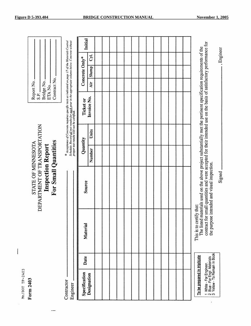
Figure D 5-393.404 BRIDGE CONSTRUCTION MANUAL November 1, 2005

November 1, 2005 BRIDGE CONSTRUCTION MANUAL Figure E 5-393.404
5-393.405 BRIDGE CONSTRUCTION MANUAL November 1, 2005
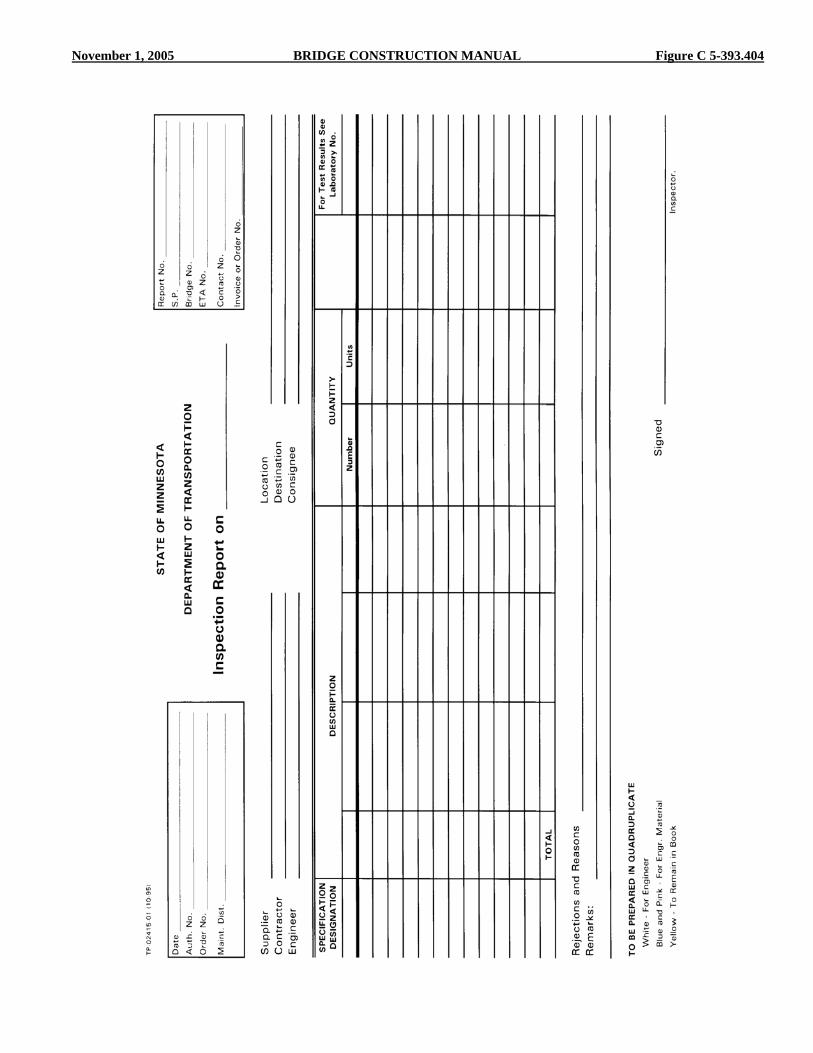
Final inspection and acceptance of structural metals is the responsibility of the Project Engineer. If material without a signed inspection tag is incorporated into the work, written notification is to be provided by the Project Engineer. Whenever it is necessary to make field inspection of structural metal items, be certain to prepare Form 2415 (see Figure C 5-393.404) as a documentation of the inspection and forward a copy to the Structural Metals Engineer. This form is used when there is a single vendor of structural metal items. When there are multiple vendors of structural metal items, prepare Form 2403 (see Figure D 5-393.404). After all materials on a project are inspected and tagged, a confirmation letter will be generated by the Structural Metals Inspection Unit that lists the items inspected, their quantities, and the date of inspection. A copy of this form (see Figure E 5-393.404) will be sent to the Project Engineer. Through the use of tags and inspection reports, the Structural Metals Inspection Unit will endeavor to keep the Inspector at the job site fully informed of all inspections performed by them. If the job site inspector has any doubts about whether or not materials have been shop inspected or are supposed to be inspected by the Structural Metals Inspection Unit, they should contact the Structural Metals Engineer for verification. The following is a list of some of the most common items that Structural Metals Inspection Unit is responsible for inspecting: 1. Pedestrian Bridges 2. Anchor bolts and assemblies 3. Bearing Assemblies 4. Drains 5. Expansion joints 6. Galvanizing 7. Hardware 8. High mast light poles 9. Light poles 10. Metal traffic barriers 11. Miscellaneous steel items 12. Overhead signs 13. Pins 14. Railings 15. Coatings (paint, galvanizing, metallizing) 16. Signal poles 17. Sole plates 18. Steel bridge superstructures 19. Steel diaphragms 20. Elastomeric Bearing Pads 5-393.405 FIELD INSPECTION OF MATERIALS In general, all structural metals will have been inspected by representatives of the Structural Metals Inspection Unit prior to shipment. The material may arrive on the job site before a report of this inspection has been received in the field, but should not be incorporated in the work until the shop inspection has been verified. (See 5-393.404 for additional information.) All materials, even though previously inspected, should be given a thorough visual inspection at the time of delivery. The Specifications clearly provide that the “Final
inspection and acceptance of materials will be made only at the site of the work.” Frequently materials are damaged or change in quality while in storage or during transit, and for that reason shop inspection and approval cannot be considered as assurance of final acceptance. See 5-393.416, Straightening Bent Material, and Specification 2402.3 regarding repair of bent or damaged members. Corrections should be made before proceeding with any erection or assembly that would result in more difficult repair or replacement of deficient materials. Structural metals inspection includes coatings inspection. Site Inspectors should carefully inspect the coated items for damage and require repair of damaged areas. Structural metals are usually transported to the job site by truck or railroad cars. Prior to unloading, each piece should, if possible, be given a complete visual inspection by the Site Inspector and any damaged pieces should be noted. Pictures taken of damaged pieces may be very useful at a later date. The Inspector should check the fabricator’s invoices against the material received, and note any discrepancies. Unloading and handling must be accomplished by methods that will not damage the members. Cable slings around the member, using soft-wood protection blocks, is the recommended method of pick-up. Finished holes, field connection holes or girder attachments should not be used as points of pickup. A well drained area in the vicinity of the bridge site, free of excessive vegetation, should be selected for storage. The members should be placed on timber blockings, skids, or platforms above probable high water. Beams and girders should be handled and stored in an upright position and securely shored to prevent over-turning. Metal items which are delivered to the job site, and for which no shop inspection has been made, should receive a complete inspection as soon after arrival as is practicable. In this case, the Site Inspector should call the Structural Metals Inspection Unit as soon as possible to discuss how inspection will be accomplished. If the inspection is to be made by the field inspector, information should be obtained from the Structural Metals Inspection Unit regarding the extent of inspection, documentation required, etc. Whenever it is necessary to make a field inspection of structural metals items, be certain to prepare Form 2415 (see Figure C 5-393.404) as a documentation of the inspection and forward a copy to the Structural Metals Engineer. Structural metals furnished by the Maintenance Area should be reported on Form 2415. If bridge pins or other structurally significant items are furnished, the inspector should call the Structural Metals Engineer to arrange for inspection. The bridge number or project number from which the material was salvaged should be listed for used materials. 5-393.406 FIELD LAYOUT Soon after the Contractor has completed concrete placement for an abutment or a pier cap, the surfaces which are to receive

November 1, 2005 BRIDGE CONSTRUCTION MANUAL 5-393.407
bearings should be closely checked for irregularities. It is normally expected that some correction will be required to obtain a suitable bearing surface, as required by Specification 2401. The Contractor should be notified as soon as possible to determine which areas will require correction and the approximate extent of the correction. Bearing surfaces should be true and smooth to provide full and uniform bearing. Elevations should be taken as soon as the bearing surfaces are finished so that the need for shims or fill plates can be determined. Filling with concrete or other materials, to raise the final elevations or level of a bearing area, should be avoided. Neat cement may be used to smooth roughness created by the float finish, to fill minor irregularities and to provide a tight seal. The field layout of substructure units is covered in section 5-393.050 of this manual. This section should be reviewed before the final centerline of the bridge and centerline of the unit are marked. The data for all span distances should be tabulated so that any minor adjustments can be made advantageously. When the final location of the centerline of bearing has been determined, it should be so marked on the top of the pier. Pencil marks on the concrete will usually be satisfactory if they are to be used within a few days, but a more permanent marking obtained with a red or blue chalk line or by scribing a line with the corner of a file or other sharp tool is usually preferable. 5-393.407 FALSEWORK The applicable requirements of Specification 2401.3B, together with section 5-393.200 of this Manual, are the basis for the design and construction of falsework and forms. Steel is assumed to have a mass of 7850 kg/m3 (490 lb/ft3). A. Plans The Contractor should prepare plans of the falsework design. When the Special Provisions require the submittal of the falsework plans to the Engineer for approval, the inspector should review these plans and make his or her comments and recommendations, prior to the submittal to the Engineer for approval. Special attention must be given to vertical and horizontal clearances, so that the work may be accomplished without disturbing the falsework as erected. B. Construction Falsework construction should conform to Specification 2401.3B, to the extent applicable, together with Section 5-393.200 of this manual and the following: 1. Falsework bents should be constructed to provide a
minimum clearance of 600 mm between the falsework caps and lower flanges or members of the structure which are to be supported thereon to provide enough space for the jacking and bolting of such members.
2. The bearing capacity of falsework piles should be checked by the Contractor’s forces as they are driven to make certain that they will support the load to be imposed. A record of the driving should then be furnished to the Engineer. It should be understood that any records kept by the inspector in this regard are for informational purposes only, and that it is the responsibility of the Contractor to provide safe and adequate construction.
Erection drawings may contain only a match marking diagram, particularly for simple structures. For more complicated structures, however, drawings should be furnished which show the exact erection sequence and procedure. These drawings should indicate, by steps, the sequence of erection, types of equipment to be used, mass of equipment which is to be placed on any part of the structure, and complete details for falsework bents and spans. When the erection drawings indicate procedures which may place temporary loads on the bridge which may be in excess of design loads, a complete analysis of the stresses should be supplied by the Contractor. These stresses may be checked by the Engineer in the field or, if complicated analysis is involved, the drawings may forwarded to the Bridge Section for review and checking. No loads which would create stresses in excess of those indicated under Design Data on the plans should be permitted, except when specifically authorized by the Bridge Engineer. 5-393.408 GENERAL ERECTION Before starting erection, the Inspector should read and study thoroughly all Specifications, Contract Plans, Shop Drawings and Special Provisions pertaining to the work. If discrepancies exist between them, it must be remembered that the Special Provisions govern over the Plans and Specifications, and that the Plans govern over the Specifications. Refer to Specification 1504 to clarify issues related to coordination between Plans, Specifications and Special Provisions. It is good practice to underline notes or specifications of particular concern, so that they will be less likely to be overlooked during erection. Make sure to check the layout and elevations before erection is started. The layout should be verified by rechecking the location of the center line of each substructure unit or the location of “Working Points” as shown in the Plans and as specified in the “Survey and Staking” Section of this manual. Also, elevations which could affect the fit of members to be erected should be rechecked to detect possible errors or to determine if settlement of the substructure units has taken place. Convenient reference points or lines should be established to enable the Inspector to continuously check the accuracy of alignment, length, and elevations during erection. Some of these reference points or lines may be scribed on the

5-393.409 BRIDGE CONSTRUCTION MANUAL November 1, 2005
substructure units. The inspector should verify the location of these reference points with the Contractor (possibly an erecting contractor). Check match markings before erection is started. Match markings, lengths, sizes, and weights of the members should be compared with those shown on the shop detail drawings. As the erection progresses, the inspector should compare the diagram of assembled members’ match markings to verify that the members have been placed in their correct position. The Inspector should make a study to determine which surfaces should be painted before erection. Surfaces which will be difficult to access after erection should be spot coated and painted with the required field coats before erection. All painting and sandblasting of contact surfaces should be done in the shop. Painting should be done according to the Contract requirements. See Surface Preparation and Painting Structural Steel, Section 5-393.450 of this manual for additional information. Before erection is started, the inspector should discuss the method of erection with the Contractor. Special emphasis should be placed on the use of safe construction practices. Some dangerous practices are: (1) lifting too heavy a load for the capacity of the lifting or carrying equipment; (2) booming crane out too far with load; (3) ignoring the manufacturers recommended practice for operation of erection equipment; (4) dropping members; (5) insufficient guying and bracing of members against wind pressure; and (6) leaving a single girder unsupported for extended time periods. Regardless of any suggestions the inspector may offer, the Contractor remains responsible for the safe handling of the structural members. The Contractor must, at all time, provide handrails, safety nets, or cable systems for attachment of safety belts and other measures adequate to provide reasonably safe working conditions for inspectors. Inspectors should wear approved hard hats at all times when in the contractor’s work area. To avoid collapse of an unsupported girder, a minimum of two girders should be connected together prior to suspending operations for the day. Handling and movement of structural members frequently requires or encourages supporting these members at points other than those for which design stresses were computed, and in some cases completely reverses the stresses. Therefore, it is important that consideration be given to these activities. A member may, for instance, support a considerable load in addition to its own mass when supported at each end, but may fail when picked up at midpoint. Members should not be dropped, nor should they be lifted using connection holes at attachments. A recommended method of pick-up is to use cable slings around the member with wood blocks to prevent damage. Most members of near uniform cross section can be safely picked up, using a two sling attachment, at about the one-fifth point from each end of the members. For members of unusual
size or shape, advice should be obtained to verify pick up points and safe handling methods. 5-393.409 ERECTION PINNING AND BOLTING OF
FIELD CONNECTIONS During erection, drift pins are used to insure proper alignment of the connecting parts and erection bolts are used to insure close contact of the connecting parts. Most connections or splices are pinned and erection-bolted at or near their final position, but some connections are pinned and bolted on the ground and the members later moved to their final location in the structure. Before erection, holes should be given a careful inspection as to size, shape and alignment. All holes should be true to the shape and size specified, clean-cut, perpendicular to the axis of the member, and free from all burrs and distorted, torn or jagged edges. Any holes which are undersized or distorted should be marked for reaming. It is good practice to keep a record of the location of these holes. This record should be referred to prior to bolting to make certain that the reaming has been done. For a bolt, the minimum distance from the center of the hole to a rolled or a machine finished edge should be 1 1/2 times the diameter of the bolt. For sheared or flame cut edges this distance should be increased by 6 mm (1/4 in.). Contact the Structural Metals Engineer, Bridge Office, if holes are in the wrong location or more than ten percent of the holes are undersized, oversized or distorted. Drift pins and erection bolts should be used in equal proportions and should be located to effectively hold the connecting members in close contact and in correct position during all bolting operations. Important connections in simple beams, girders, floor systems, etc., should have at least 50 percent of the holes filled with drift pins and erection bolts. The number of drift pins and erection bolts for continuous and cantilevered beam or girder spans will be determined by the Engineer for the stresses developed in the connection during erection. A325 high-strength bolts may be used for erection bolts, and then reused for the final connection unless damaged. The Inspector should check the high-strength bolts used for erection bolts before they are incorporated in the connection. The diameter of the drift pins should not be larger than the diameter of the connection holes and should not be smaller than the diameter of the connection holes, less 1 mm (1/32 in.). The erection bolts should be the same nominal diameter as the bolts. Erection washers should generally be used with erection bolts. After pinning and erection bolting of all connections, all holes that do not freely admit a bolt should be cleared by reaming.

November 1, 2005 BRIDGE CONSTRUCTION MANUAL 5-393.410
The use of drift pins in lieu of reaming to enlarge holes should not be permitted. 5-393.410 ERECTION OF BEARING ASSEMBLIES. Follow these guidelines: 1. A bearing assembly is a device for transferring
superstructure loads to the bridge seat. Included in this category are masonry bearing plates, shoes, rockers and rollers, elastomeric pads, pot and disk bearings and their various combinations.
2. Prior to setting the bearing assemblies, the inspector
should check the bridge seats to insure that they provide a uniform bearing surface at the proper elevation. Preparation of bearing areas is covered in Section 5-393.406, of this manual. Also check the bottom of the bearing assembly for warpage during fabrication.
3. Immediately prior to assembly, temporary protective
coatings should be removed from pins and pin holes and all extraneous material should be removed from contact surfaces. After cleaning, the pins and pin holes, should be given a coat of specified prime, and the pins should be inserted in the holes. This procedure should be used except where bronze brushings are used.
4. Unless otherwise indicated in the Plans, bearing
assemblies such as rockers, roller nests and hangers for suspended spans should be set so as to be plumb, or at the designated tilt, at a temperature of 7EC (45EF).
5. Pot and disk bearings shall be set for the centerline of
bearing to be centered at a temperature of 7EC (45EF). 6. Anchor rods must be installed to the full depth as shown
in the plans. If anchor rod location hits rebar, contact the Bridge Office.
Prior to erecting beams, girders, diaphragms, etc. the Engineer should verify that all members have been shop inspected and approved. See Section 5-393.404 of this manual. 5-393.411 ERECTION OF BEAMS, GIRDERS,
DIAPHRAGMS, ETC. See Specification 2402.3 for the extent of erection required before starting placement of permanent fasteners, and for the requirements for erection of pins and bolts. Elevations should be taken on the steel at splice points prior to starting placement of permanent fasteners to determine the necessity for vertical adjustment. This is particularly true when there is a field splice on each side of a support. Plan control dimensions are based on beams theoretically straight and of tubular dimensions. No allowance is made in plans for dead load deflection or rolling tolerances within a given section. Slight variation may result from these factors which
will not require adjustment, but if adjustment is necessary the following should be considered: (a) both points should vary from the plan position by the same amount and in the same direction; (b) top and bottom flanges of beams should be brought into vertical alignment; (c) adjustment of elevations can be made by jacking at the low splice or by temporarily loading the beams at the location of the high splice. The position of the erection bolts should be checked during or after the jacking or loading operations to insure that undesirable stresses have not been introduced into the members. Binding of the free erection bolts and heavy resistance to jacking or loading would indicate that erection stresses have been introduced, and these stresses must be relived prior to placement of permanent connectors. Steel members should be at their final relative elevation and in proper alignment prior to placement of permanent connectors. 5-393.412 ERECTION OF EXPANSION DEVICES When the Contractor erects and adjusts the expansion devices, the parts should be accurately assembled as shown on the plans and all match-marks should be followed. The materials should be carefully handled so that no parts will be bent, broken, or otherwise damaged. Bearing surfaces and surfaces to be in permanent contact should be cleaned before the members are assembled. Unless otherwise indicated in the plans, expansion devices should be set so as to have the specified opening at 7EC (45EF). Additional information on expansion devices can be found in Section 5-393.370 of this manual. Finger joints should be aligned to permit free movement without lateral contact. Immediately prior to placing any deck concrete, recheck expansion devices for (1) correct elevation (2) correct amount of opening at the temperature during the check and (3) any foreign material which may have entered the joint during construction. In cases where large deflections occur in deep girders, rotation of the top end of the girder may cause the two extrusions to expand apart during deck construction. The Contractor shall provide movement capability for this joint during deck placement, and set initial opening to compensate for expected deflection. 5-393.413 ERECTING METAL RAILING When erecting metal railing and prior to placement of concrete in the rail base, consideration of any necessary adjustment of the metal rail anchorages is critical.

5-393.414 BRIDGE CONSTRUCTION MANUAL November 1, 2005
The spacing of the rail post anchorages should be in accordance with approved shop detail drawings. For curved bridges, the inspector should ascertain along which curved line the rail post spacings are dimensioned. Lateral clearances and projection of the rail post anchorages should be closely checked. Cast-in-place anchorages for metal rail posts should be supported rigidly to prevent movement during concrete placement. To ensure proper fit, exact field measurements of anchorage locations are needed by the fabricator and are generally furnished by the contractor. The bearing areas under the rail post base should be finished to provide a uniform contact surface. Any grout which is left on the threads of the anchorages during concrete operations should be cleaned off immediately. Drilled in anchorages are permissible for most railings and are necessary where the slip form method of construction is used. A template is necessary for drilling if anchorages are drilled prior to placement of railing. Shims should be used to properly align the posts. The edge of the base plate should be caulked for tightness after the posts have been bolted in their final position. No voids should be left which would permit admission of water. 5-393.414 BOLTING OF PERMANENT FIELD
CONNECTIONS Except when otherwise specifically required by the contract, permanent field connections may be made using bolts meeting the requirements of the Standard Specifications. Bolting is covered under Specification 2402 and includes conventional “A325 high-strength” bolts and “pin bolt.” A490 high-strength bolts are not normally used in structural connections. Welded connections are only used when specified by the Contract or when specifically permitted by the Engineer and are covered under Specification 2471. Regardless of the type of connectors used, placement of the permanent connectors should not be started until the various parts of a joint have been properly aligned and drawn into full contact. See Field Fit-up under Specification 2402. When high-strength bolts are to be used for the connection, the same bolts may be used for fit-up by applying partial tension, then final tensioning these bolts after the remaining bolts for that connection have been placed. The requirements for the use of pin bolts specify that the driving tool be capable of partial swaging; this will permit the use of the same pin bolts for fit-up, with the final swaging applied after the remaining bolts for that connection have been placed and fully swaged. The use of the same bolts for fit-up as will be used for permanent bolting is permitted as an expedient and is not intended as a requirement should the Contractor desire to use conventional erection bolts for that purpose.
Bolts (“high-strength” or “pin bolts”) should be installed with the heads on the outside face at web splices on fascia beams and girders, and with the heads down on flange splices on all beams and girders spanning a highway. The principle of high-strength bolting is that the bolts are tightened to a high tension, producing clamping forces which enable the faying surfaces to carry loads by friction. The two accepted methods of tightening high-strength bolts to provide the necessary clamping force are the turn-of-nut and direct tension indicator methods. Direct tension indicators are typically specified for all field connections. Conditions which must exist before bolting is started are as follow: 1. Bolts, nuts and washers must have been approved by the
Materials Lab or the Structural Metals Engineer. (See Tables C - H 5-393.414 for information on bolts, nuts, and washers.) "Metric bolts" are currently not permitted for use on Department projects as tightening procedures have not yet been established for metric thread configurations. Information on metric sizes is included, however, as it is anticipated that procedures will be available in the near future.
2. It is important to visually inspect bolts and nuts when they
are first delivered to the job and each day during the bolting operation. For galvanized nuts, the nut threads must contain a dyed lubricant. Also, nuts should be tested to show that they are able to be hand-threaded on the bolt. If the lubricant is missing or the nut cannot be hand-threaded onto the bolt, stop the bolting operation until this is corrected. Insufficient lubrication can result in inadequate tightening of the bolt and make it difficult to reach the required tension.
Bolts, nuts and washers should be free from rust, dirt or
other foreign material which may have an influence on the torque-tension ratio, and which would produce greatly varying stresses in bolts with comparable torque values. Use of proper lubricant is especially important for galvanized bolts. Bolt and nut threads should be given a visual inspection to determine whether or not they have been damaged, and that the threads are properly formed. Only A325M bolts may be reused once unless damaged.
3. Contact surfaces shall be free of grease, oil, dirt, sand or
other extraneous material. Holes for bolts shall be aligned by the use of drift pins and spud wrenches so that the bolts can be placed through the holes without being driven with a tool.
4. A torque wrench, properly calibrated and of a sufficient
size to measure maximum torque loads must be available to the inspector for use as he or she deems necessary. The inspector should follow the inspection procedures outlined in Specification 2402.3G.
November 1, 2005 BRIDGE CONSTRUCTION MANUAL 5-393.414 (2)
5. A hardened washer should always be used under the nut or bolt head element being turned, regardless of the method of tightening used, to prevent galling of the faying surface. A hardened washer under both bolt head and nut is required where full sized holes have been punched. A beveled washer is required if the outer face of bolted parts has a slope of more than 1:20 with respect to a plane normal to the bolt axis.
6. An adequate supply of power to drive the impact
wrenches is an absolute necessity. Compressed air delivered at a minimum pressure of 620 kPa (90 psi) is usually adequate for bolts 22 mm (7/8 in.) diameter and smaller; but higher pressure is needed for larger bolts. When a large number of wrenches are being driven by the same power supply, an auxiliary tank will be needed in order to provide adequate and uniform pressure.
7. Before the bolting operation begins, it is important for the
inspector to have the Contractor establish the tightening procedure that will be used. The procedure should be checked anytime the inspector feels the condition of the lubricant has changed. In this way, we are assuring that a proper tensioned connection can be made. Calibrated wrench tightening is no longer a permitted method of tensioning high-strength bolts. Laboratory testing and field experience showed that bolt tension varies considerably using this method.
8. Turn-of-Nut Tightening should follow these guidelines. a. At least three typical bolts from each lot shall be
tested in a Skidmore-Wilhelm device furnished by the Contractor to verify minimum bolt tension. (See Table A 5-393.414) The Bridge Office should be consulted if minimum tension is not achieved by the specified nut rotation (See Table B 5-393.414).
b. When the turn-of-nut method is used to provide the
required bolt tension it is important that the bolts be brought to a “snug tight” condition prior to final tightening. This will ensure that the connected parts are brought into contact with each other, and will provide a starting point from which to measure the required amount of turn. Tightening should begin near the center of a group of bolts and progress toward the edges. “Snug tight” is defined as 15 percent of the specified bolt tension by 2402.3G2d(1). The inspector must ensure that bolts are not overtightened in a “snug tight” condition as this would result in overstressing the bolt when using the turn-of-nut method. The contractor’s impact wrenches should be adjusted to give a “snug tight” condition during the Skidmore-Wilhelm testing. The job inspection wrench may be used to check for “snug tight” condition.
c. After all bolts in the connection have been brought to
“snug tight”, they shall be given the applicable turn of nut specified in Specification 2402.3G (See Table
B 5-393.414). During this rotation it is important that there be no rotation of the opposing part (head or nut). Impact wrench sockets should be marked each 90 degrees on the outer surface to enable the operator to easily measure nut rotation. If the wrench is equipped with a torque cut-off device, this device should be eliminated or bypassed during final rotation of nut.
d. Turn-of-nut tightening can be inspected by (1)
observing the rotation of each nut or bolt head, (2) requiring the impact wrench operator to mark each nut or bolt head and adjacent surface after the snug tight condition has been achieved, or (3) using a job inspection wrench as described in Specification 2402.3G. Close examination of nuts after application of required tightening will generally disclose marks near the edge of each flat surface and slight burnishing of the edges.
9. Direct Tension Indicator (DTI) Tightening a. Direct tension indicators are specially fabricated
washers with slight protrusions projecting above the flat bearing surface. The DTI shall be placed under the non-turned end of the fastener. These protrusions flatten out under load and the amount of flattening is used to measure the bolt tension. A feeler gage measures the gap remaining after tightening. Direct tension indicators are to be installed in accordance with the manufacturer’s directions except the feeler gage shall be able to be inserted into at least one space between the protrusions. Specification 2402.3G requires verification of minimum bolt tension (see Table A 5-393.414) from each lot of bolts and direct tension indicators using the Skidmore-Wilhelm device.
Prior to starting installation of pin bolts, at least three bolts of each size and length, from each lot of bolts to be used in the work, should be tested in a device (furnished by the Contractor) capable of indicating actual tension in the bolt. The indicated tension at the time the pin tail breaks off must not be less than the tension required for high-strength bolts of the same size. See Table A 5-393.414. Prior to installation of pin bolts, the holes must be checked for proper alignment (See Specification 2471). The pin bolt is placed in the properly prepared hole. See 5-393.409 for special requirements concerning direction of head. A special power tool clamps onto the pin tail as the power is triggered, and draws the connected parts together. As the tension increases, an anvil in the nose of the power tool swages the collar into the locking grooves on the body of the pin bolt. The tool continues to draw the pin tail, until failure occurs at a circumferential groove fabricated into the pin to reduce the net section. (See Specification 2402, Field Fit-up, and 5-393.409, regarding drawing the parts into full contact before making the permanent connection).

Tables A & B 5-393.414 BRIDGE CONSTRUCTION MANUAL November 1, 2005
Bolt Length(as measured from
underside of head toextreme end of point)
Both faces normalto bolt axis
One face normal to boltaxis and other face sloped
not more than 1:20(bevel washer not used)
Both faces sloped notmore than 1:20 fromnormal to bolt axis
(bevel washers not used)
Disposition of Outer Faces of Bolted Parts
Up to and including4 diameters
Over 4 diametersbut not exceeding12 diameters
1/3 turn
1/2 turn
1/2 turn
2/3 turn
2/3 turn
5/6 turn
Nut Rotation From Snug Tight Conditiona
b
Note:These relationships have not been determined for metric sizes.
Nut rotation is relative to bolt, regardless of the element (nut or bolt) being turned.Tolerance on rotation is 1/6 turn (60 F) over and nothing under.
When bolt lengths exceed 12 diameters, the required rotation must be determined by actual tests in asuitable tension device simulating the actual conditions.b
a
Table B 5-393.414
Bolt Sizein.
Fastener Tension
Minimum Fastener Tensionfor A325 bolts
kips
1/25/83/47/81
1 1/81 1/41 3/81 1/2
over 1 1/2
1219283951567185103
0.7xT.S.
Note: Equal to 70 percent of specified minimum tensile strength of bolts, rounded off to the nearest kip.
Table A 5-393.414
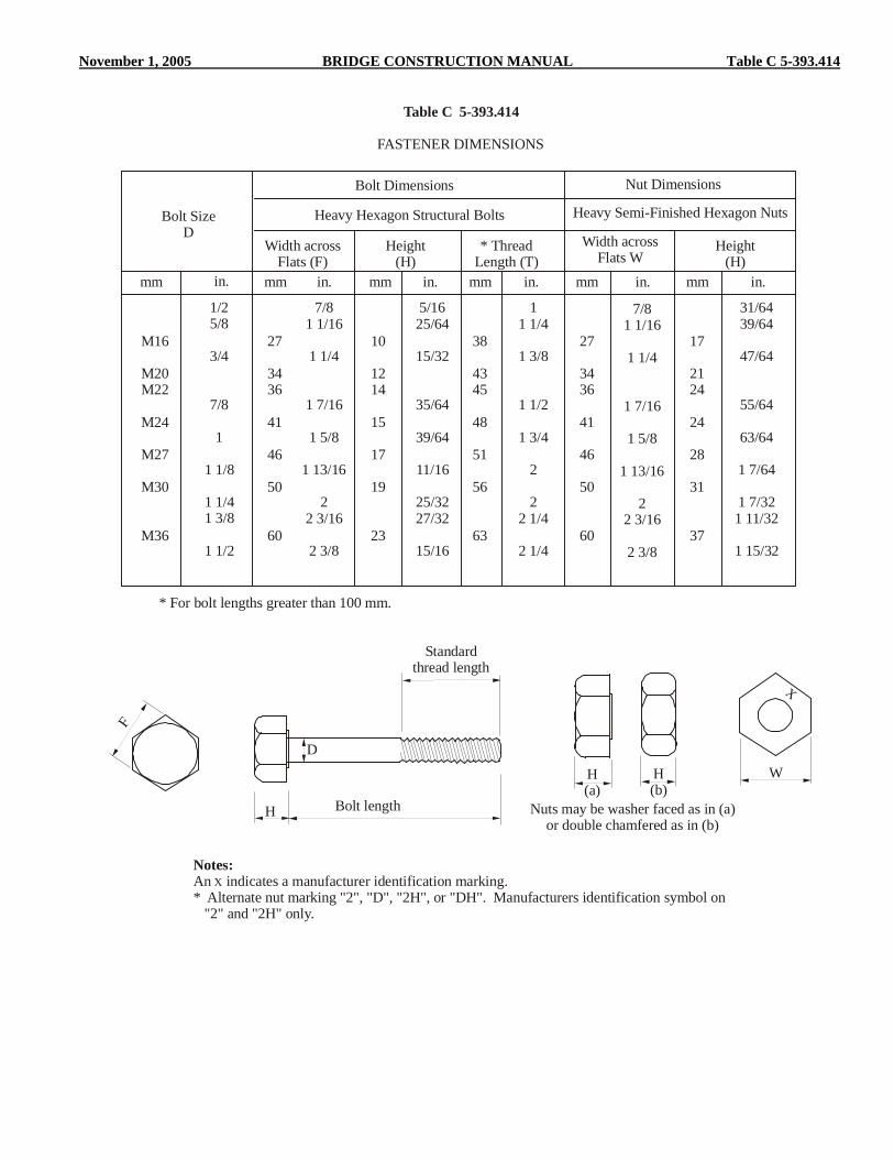
November 1, 2005 BRIDGE CONSTRUCTION MANUAL Table C 5-393.414
Bolt SizeD
Width across Flats (F)
Height(H)
* Thread Length (T)
* For bolt lengths greater than 100 mm.
Height(H)
Width acrossFlats W
mm mm mm mm mm mmin. in. in. in. in.in.
Table C 5-393.414
Bolt Dimensions Nut Dimensions
1/25/8
3/4
7/8
1
1 1/8
1 1/41 3/8
1 1/2
7/81 1/16
1 1/4
1 7/16
1 5/8
1 13/16
22 3/16
2 3/8
5/1625/64
15/32
35/64
39/64
11/16
25/3227/32
15/16
11 1/4
1 3/8
1 1/2
1 3/4
2
22 1/4
2 1/4
7/81 1/16
1 1/4
1 7/16
1 5/8
1 13/16
22 3/16
2 3/8
31/6439/64
47/64
55/64
63/64
1 7/64
1 7/321 11/32
1 15/32
M16
M20M22
M24
M27
M30
M36
27
3436
41
46
50
60
10
1214
15
17
19
23
38
4345
48
51
56
63
27
3436
41
46
50
60
17
2124
24
28
31
37
Heavy Hexagon Structural Bolts Heavy Semi-Finished Hexagon Nuts
FASTENER DIMENSIONS
H(a)
H(b)
Nuts may be washer faced as in (a)or double chamfered as in (b)
H
D
Bolt length
Standardthread length
X
Notes:An indicates a manufacturer identification marking. * Alternate nut marking "2", "D", "2H", or "DH". Manufacturers identification symbol on "2" and "2H" only.
X
F
W

Table D 5-393.414 BRIDGE CONSTRUCTION MANUAL November 1, 2005
Minimum gripMaximum grip
Standardthread length
Length of incomplete thread
Projection
* For metric sizes with the bolt lengths exceeding 100 mm add 7 mm to the thread length.
Bolt SizeD
Standard ThreadLength *
AvailableProjections mm
AvailableProjections in.
mm mm min. min.in. in. max. max.
1/25/8
3/4
7/8
1
1 1/8
1 1/41 3/8
1 1/2
11 1/4
1 3/8
1 1/2
1 3/4
2
22 1/4
2 1/4
3/327/32
7/32
7/32
11/32
15/32
11/3215/32
11/32
8/3213/32
13/32
13/32
17/32
21/32
17/3221/32
17/32
M16
M20M22
M24
M27
M30
M36
31
3638
41
44
49
56
1.00
1.251.25
1.5
1.5
1.75
2.00
3.00
3.753.75
4.50
4.50
5.25
6.00
NominalBolt Length
mm in.
Bolt Diameter
1 1/2
2
2 1/2
3
3 1/2
4
4 1/2
5
5 1/2
66 1/2
77 1/2
88 1/2
9
9/16-3/4
1 1/16-1 1/4
1 9/16-1 3/4
2 1/16-2 1/4
2 9/16-2 3/4
3 1/16-3 1/4
3 9/16-3 3/4
4 1/16-4 1/4
4 9/16-4 3/4
5 1/16-5 1/45 9/16-5 3/4
6 1/16-6 1/46 9/16-6 3/4
7 1/16-7 1/47 9/16-7 3/48 1/16-8 1/4
-
9/16-3/4
1 1/16-1 1/4
1 9/16-1 3/4
2 1/16-2 1/4
2 9/16-2 3/4
3 1/16-3 1/4
3 9/16-3 3/4
4 1/16-4 1/4
4 9/16-4 3/45 1/16-5 1/4
5 9/16-5 3/46 1/16-6 1/4
6 9/16-6 3/47 1/16-7 1/47 9/16-7 3/4
-
-
9/16-3/4
1 1/16-1 1/4
1 9/16-1 3/4
2 1/16-2 1/4
2 9/16-2 3/4
3 1/16-3 1/4
3 9/16-3 3/4
4 1/16-4 1/44 9/16-4 3/4
5 1/16-5 1/45 9/16-5 3/4
6 1/16-6 1/46 9/16-6 3/47 1/16-7 1/4
50
60
70
80
90100
110
120
130
140150
170
200
250300
13-19
23-29
33-39
43-49
53-5963-69
66-72
76-82
86-92
96-102106-112
126-132
156-162
206-212256-262
-
14.5-22
24.5-32
34.5-42
44.5-5254.5-62
57.5-65
67.5-75
77.5-85
87.5-9595.5-105
117.5-125
147.5-155
197.5-205247.5-255
-
10-19
20-29
30-39
40-4950-59
53-62
63-72
73-82
83-9293-102
113-122
143-152
193-202243-252
-
-
10.5-21
20.5-31
30.5-4140.5-51
43.5-54
53.5-64
63.5-74
73.5-8483.5-94
103.5-114
133.5-144
183.5-194233.5-244
1/2" M16 M22 7/8" M24 M30 1 1/4"
Range of Grip Lengths (in.) (mm)
Grip Lengths for A325M and A325 Bolts(includes allowance for one hardened washer)
Table D 5-393.414

November 1, 2005 BRIDGE CONSTRUCTION MANUAL Tables E & F 5-393.414
App
roxi
mat
ely
8m
m(5
/16i
n.)
AmericanStandardBeam orChannel
(with16 2/3%slope)
According to Specifications for this type of section, a16 2/3% slope, bevel washer must be used on thesloped surface of the flange under bolt head or nut.
Hardened Bevel Washers
Bolt Size Hole Diametermm in. mm in.
1/25/8
3/4
7/8
1
1 1/8
1 1/4
9/1611/16
13/16
15/16
1 1/16
1 1/4
1 3/8
M16
M20M22
M24
M27
M30
M36
18
2224
26
30
33
39
16 2/3% slope bevelwasher for American
Standard Beam or Channel
Note:A 44 mm (1 3/4 in.) square washer is furnished for bolt diameters up to and including M24 (1 in.).A 57 mm (2 1/4 in.) square washer is furnished for M27-M36 (1 1/8 in. and 1 1/4 in.) diameter bolts.
A325M8S
X
Type 1
X
A325M8S
Type 2
X
A325M8S3
Type 3
3
Type 3
3M
Type 3
A325X
Type 1
XA325
Type 3Type 2
XA325
3
Type 3Type 1
8S3
Type 3
X
X X
M
Type 1
X
X
2
Type 2 *Type 1
X
8S
X
Type 2
8S
Metric EnglishBolts
Nuts
Washers
TYPICAL FASTENER MARKINGSFOR A325 AND A325M BOLTS
Table E 5-393.414
Table F 5-393.414

Tables G & H 5-393.414 BRIDGE CONSTRUCTION MANUAL November 1, 2005
B44 (1 3/4 in.)
44 (1
3/4
in.)
Bolt Size Hole Diametermm in. mm mmin. in.
1/25/8
3/4
7/8
7/169/16
11/16
25/32
9/1611/16
13/16
15/16
M16
M20M22
M24
18
2224
26
14.0
17.519.2
21.0
B *
ID ID
OD
OD
T T C
Bolt Size Outside Diameter(OD)
Inside Diameter(ID)
Thickness (T)
mm in. mm mm mm mm mmin. in. in. in. in.
1/25/8
3/4
7/8
1
1 1/8
1 1/4
1 1/161 3/8
1 1/2
1 3/4
2
2 1/4
2 1/2
17/3211/16
13/16
15/16
1 1/16
1 1/4
1 3/8
.097
.122
.122
.136
.136
.136
.136
.177
.177
.177
.177
.177
.177
.177
7/169/16
21/32
25/32
7/8
1
1 3/32
M16
M20M22
M24
M27
M30
M36
33
4143
49
55
59
71
18
2224
26
30
33
39
3.1
3.13.4
3.4
3.4
3.4
3.4
4.6
4.64.6
4.6
4.6
4.6
4.6
14.0
17.519.2
21.0
23.6
26.2
31.5
Min. Max.C
Hardened Clipped Bevel Washers
Table G 5-393.414
Table H 5-393.414
Hardened Round Washers

November 1, 2005 BRIDGE CONSTRUCTION MANUAL 5-393.415 (1)
The inspector should make certain that proper fit-up has been made before permitting final swaging of any pin bolts in a joint, since there is no second chance to do so as with conventional high-strength bolts. The inspector should also observe the installation from time to time to make certain that the power-tool is not used in a way to break the pin tail prematurely by applying bending stresses in addition to direct tension. Additionally, the anvil and die of the power tool should be checked for excessive wear that might result in improperly formed collars. As previously mentioned, the inspector should observe that the bolting begins near the center of a group of bolts and progress toward the free edges. 5-393.415 WELDING The material covered in this section of the manual is limited to field welding. Field welding is defined as that welding which is performed after the shop fabricated material is delivered to the bridge site. Quality Control (QC) is the responsibility of the Contractor. As a minimum, the Contractor shall perform inspection and testing prior to assembly, during assembly, during and after welding, and additionally, as necessary to assure that materials and workmanship conform to the requirements of the contract documents. No welding including weld repair should be permitted unless shown in the plans or approved by the Engineer. Field welding on primary stress carrying members for the purpose of providing supports for falsework brackets, etc., will not be permitted. Welding may be permitted on shear lugs or other appurtenances which are not an integral part of the primary stress carrying member. Screed rail supports may be welded to the top flange with 6 mm (1/4 in.) fillet welds in the positive moment area, but not in the negative moment area (Area “A”.) Furthermore, if any welding is to be performed on major structural components as defined in 2471.3A1, the Inspector should contact the Structural Metals Engineer for welding requirements before the welding is performed. The Inspector should study the steel design plans and shop drawings in advance to become familiar with the construction details and provisions for welding. Weld symbols are shown in Figure A 5-393.415. Welding should not be allowed when the ambient temperature is lower than 78EC (0EF), when surfaces are wet or exposed to rain, snow, or high wind velocities, nor when welders are exposed to inclement conditions. Immediately prior to any welding, the Inspector must determine that dimensions are correct, fit-up at joints is proper, and that surfaces and edges to be welded are smooth, uniform, and free from fins, tears, cracks, and other discontinuities which would adversely affect the quality or strength of the weld. Surfaces to be welded and surfaces
adjacent to a weld should also be free from loose or thick scale, slag, rust, moisture, grease, paint, galvanizing, and other foreign material that would prevent proper welding or produce objectionable fumes. The base metal temperature shall be a minimum of 10EC (50EF) before welding will be allowed to be performed. Except as modified by the project plan, all welding shall be performed in accordance with 2471.3C. Except for stud welding using a stud welding gun, all field welding on MnDOT projects require the use of certified welders. MnDOT has a test procedure for field welders. Field welders who pass the MnDOT welder qualification test are certified for work on our projects. A wallet size card is issued (cards must be renewed periodically) to each certified welder. A list of welders currently certified is on file in the Bridge Office. Inspectors should request proof of current certification before the welder is allowed to weld. In addition, the welder is required to follow an approved Welding Procedure Specification (WPS). The Contractor shall submit all WPS's to the Metals Quality Engineer for approval before starting any welding. The WPS shall describe the type of joint being welded, current and amperage allowed, electrode and preheat required, and other essential variables needed to produce an acceptable weld. Inspectors are required to have a copy of the WPS and make sure it is being followed. A welder certification card and report card is shown in Figure B 5-393.415. Any questions regarding welder certification or weld procedures should be directed to the Metals Quality Engineer. The Inspector should obtain from the Contractor certified copies of test reports made on electrodes of the same class, size and brand, and which were manufactured by the same process and the same materials as the electrodes being used on the project. These test reports should be submitted to the Metals Quality Engineer. To facilitate inspection of welding, the Contractor is required by the Specifications to provide all necessary hand shields, glasses, etc., for the Inspector. Structural defects resulting in weak welds, may be in the form of porosity, slag inclusions, incomplete fusion, inadequate penetration, undercutting, and cracking. The correction for all of these defects would be to completely remove the defective portion of the weld to sound metal and reweld. The Contractor shall submit a repair WPS to the Structural Metals Engineer for approval. The removal of welds should be accomplished without damage to the adjacent metal. Porosity is the entrapment of voids in the weld and is generally caused by the use of excessive welding heats or incorrect manipulation of the welding electrode. Slag inclusions are best avoided by use of proper welding techniques and cleaning procedures, both before and during welding. Incomplete fusion is the failure to unite together, through fusion, adjacent layers of weld metal or weld metal and base metal. Inadequate penetration is a condition where the weld metal and base metal are not fused together for the full depth of the

5-393.415 (2) BRIDGE CONSTRUCTION MANUAL November 1, 2005
joint. Undercutting is the melting or burning away of the base metal at the toe of the weld, which results in a reduction in cross-section of the metal. Cracking of welded joints is the result of internal stresses, within the weld, exceeding the ultimate strength value. Figure C 5-393.415 shows examples of good welds and the results of poor welding techniques. If there are any questions on the acceptability of a weld or if a crack occurs on a major structural component, the Metals Quality Engineer should be contacted. The inspector should, at suitable intervals, observe the welding techniques and performance of each welder to make certain that applicable requirements are met. The inspector must make certain that the size, length and location of all welds conform to the requirements of the contract and that no unspecified welds have been added without approval. The size and contour of welds can be measured using suitable gauges. Visual inspection for cracks in welds, and base metal, and for other discontinuities should be aided by strong light magnifiers or such other devices as may be helpful. In addition, the Inspector must make certain that approved weld procedures are being followed. The Inspector should observe the welding operation to see that the weld is made in a manner creating fusion of the metal without boiling, running or excessive spatter. Check tests of qualified welders may be required at any time the welding inspector directs and as may be determined and ordered by the Engineer. Only one arc should be operated from a single power source. The Inspector should watch for arc strikes outside the area of permanent welds on any base metal. Cracks or blemishes caused by arc strikes must be ground to remove all of the defect. If arc strikes occur on a major structural component, the Metals Quality Engineer should be contacted. Before welding over previously deposited metal, all slag must be removed and the weld and adjacent base metal must be brushed clean. After all slag is removed, the finished welds should be checked as to size, shape, and quality. All welds should be free of defects such as cracks, undercutting, overlapping, objectionable irregularities, etc. The use of oversize fillet welds should be discouraged. An incorrect weld profile may indicate such weld defects as overlap, excess convexity, or excess concavity. Overlap, which may be attributed to improper technique or improper welding heat, is a weld defect in which little or no penetration occurs at the point of overlap. Excess convexity tends to produce harmful stress concentrations under load by stiffening the section unnecessarily. Correction may be accomplished by grinding to correct weld profile. Excess concavity is merely a weld of insufficient size and therefore insufficient strength. Surface irregularities such as varying widths and heights, depressions, etc., may not of themselves be weld defects. They do indicate a lack of good workmanship on the part of
the welder and they may be objectionable from the point of view of appearance. Studs are commonly used to transmit shear forces from the deck slab to steel beams. Due to OSHA related safety concerns, the studs must be field welded. Special automatic welding equipment is used for stud welding. Any automatically timed electric welding equipment of sufficient capacity to produce complete fusion between the end of the stud and the beam flange may be used. In addition, the equipment should be capable of producing a continuous weld metal fillet for the full perimeter of the stud. The welding gun, while in operation, should not be moved until the weld has solidified. At the time of welding, the studs and the areas of the beam to be welded shall be free from rust, rust pits, scale, oil, paint, moisture, or other deleterious matter. The stud base shall not be painted, galvanized, nor cadmium-plated prior to welding. Studs which do not meet this requirement should be rejected. Areas of the beam to be welded should be cleaned by surface grinding. Stud welding should not be permitted when the ambient temperature or the temperature of the beam is below 78EC (0EF) or when the surface is wet or exposed to falling rain or snow. The arc shields or ferrules must be kept dry. Any arc shields which show signs of surface moisture from dew or rain shall be oven dried at 120EC (250EF) for at least two hours before use. Before welding with a particular set-up (operator, position, amps, volts, etc.) and with a given size and type of stud, and at the beginning of each work day or shift, testing must be performed on the first two studs that are welded. The test studs should be visually examined and must exhibit full 360 degree flash. In addition to visual examination, the test consists of bending the studs after they are allowed to cool, to an angle of approximately 30 degrees from their original axes by either striking the studs on the head with a hammer or placing a pipe or other suitable hollow device over the stud and manually or mechanically bending the stud. At temperatures below 10EC (50EF), bending should preferably be done by continuous slow application of load. If on visual examination the test studs do not exhibit 360 degree flash, or if on testing, failure occurs in the weld zone of either stud, the procedure must be corrected, and two more studs be welded and tested. If either of the second two studs fails, additional welding is to be continued on separate plates of the same material, thickness and surface condition until two consecutive studs are tested and found to be satisfactory. Two consecutive studs should then be welded to the beam, tested, and found to be satisfactory before any more studs are welded to the beam. If failure occurs in the stud shank, the Metals Quality Engineer should be consulted.

November 1, 2005 BRIDGE CONSTRUCTION MANUAL Figure A 5-393.415
(N)
R
FA
L-PS(E)T
Number of spot, stud, orprojection weldsBasic weld symbol
or detail reference
(Tail omittedwhen referencenot used)
Specification, process,or other reference
Depth of preparation; size orstrength for certain welds
Groove weld size
Root opening;depth of fillingfor plug and slot welds
Contour symbol
Finish symbolGroove angle; includedangle of countersunkfor plug welds
Length of weld
Field weld symbol
Arrow connecting reference line toarrow side member ofjoint or arrow sideof joint
Weld-all-around symbolReference line
Tail
(Bot
h
Si d
es)
Arr
ow
S ide
Oth
e rS i
de
Elements in thisarea remain as
shown when tailand arrow are
reversed
Weld allaround Field Weld
MeltThrough
ConsumableInsert
(Square)
Backingor
Spacer(Rectangle)
CountourFlushor Flat Convex Concave
Groove
Square Scarf V Bevel U J Flare-V Flare-bevel
Pitch (center to center spacing of weld)
FilletPlugor
SlotStud
Spotor
ProjectionSeam
Backor
BackingSurfacing
Flange
Edge Corner

Figure B 5-393.415 BRIDGE CONSTRUCTION MANUAL November 1, 2005

November 1, 2005 BRIDGE CONSTRUCTION MANUAL Figure C 5-393.415
(A) Desirable Fillet Weld Profiles
(C) Unacceptable Fillet Weld Profiles
(D) Acceptable Groove Weld Profile In Butt Joint
(E) Unacceptable Groove Weld Profiles In Butt Joint
(B) Acceptable Fillet Weld Profiles
Note: Convexity, C, of a weld or individual surface bead shall not exceed 0.07 times the actual facewidth of the weld or individual bead, respectively, plus 1.5 mm (0.06 in.)
Size
Size
Size
Size
Size
ExcessiveConvexity
ExcessiveConvexity
Size
Size
InsufficientThroat
InsufficientThroat
Size
Size
Overlap
Overlap
Size
Size
InsufficientLeg
Size
IncompleteFusion
Size
ExcessiveUndercut
ExcessiveUndercut
Size
C CC
450

5-393.416 BRIDGE CONSTRUCTION MANUAL November 1, 2005
Studs that fail the test on the bridge beam should be removed and the area ground flush to remove any defects. The inspector should make a visual inspection of all welded stud shear connectors. After welding, arc shields must be broken free from studs to be embedded in concrete, and where practical, from all other studs. The studs, after welding, must be free of any discontinuities or substances that would interfere with their intended function. In addition, each stud should be given a light blow with a hammer and the inspector should test bend at least one stud in each 100 studs welded, to an angle of 15E. Any stud which does not have a complete end weld (360E of continuous expelled metal around base of stud), any stud which does not emit a ringing sound when given a light blow with a hammer, any stud that has been repaired by welding, or any stud which has less than normal reduction in height due to welding, should be struck with a hammer and bent 15E in the direction that will place the defective portion of the weld in the greatest tension. The studs tested that show no sign of failure should be left in the bent position. Studs that crack in the fusion zone should be removed and replaced as defined above. Studs that crack in the shank should be replaced as directed by the Engineer. Occasional minor discontinuities in the weld fillet of the studs may be repaired by adding a 8 mm (5/16 in.) fillet weld using a shielded metal-arc process with low-hydrogen electrodes in accordance with the requirements of Spec. 2471.3J4b1. Certified welders are required for repair welding. However, repeated defects should not be permitted and corrective measures as outlined above should be taken as soon as it becomes evident that modifications of the established welding procedure are needed. All containers of studs shall be identified by the heat number of the steel from which the studs were produced. Field inspectors checklist for inspection of structural metals.
Action Yes No Copies of piling mill test reports were sent to Structural Metals Unit.
Copies of approved weld procedures were sent to Structural Metals Unit.
Structural metals items had a shop inspection tag or were reported on form 2415.
Copies of welding electrode certifications were sent to Structural Metals Unit.
A list of all welders that welded on the job was sent to the Structural Metals Unit.
Action Yes No Contractor’s painting quality control form listing painter’s name, temperatures, humidity, profile, paint thickness, etc was sent to Structural Metals Unit if field painting was done.
Copy of torque and tension values obtained for turn-of-the-nut certification test was sent to the Structural Metals Unit.
5-393.416 STRAIGHTENING BENT MATERIAL Members which have become bent, crimped, or otherwise damaged should not be erected until they have been straightened or repaired to the satisfaction of the Engineer. Technical advice will be provided by the Structural Metals Engineer regarding permissible methods of straightening or repairing bent materials, and concerning conditions that may be a cause for rejection of materials. The Structural Metals Engineer should always be contacted in cases involving damage to main structural members. Only qualified personnel should be allowed to perform the work of straightening and repairing damaged structural members. Damaged sections should be straightened by methods that will not shear, fracture, or prestress the bolts, welds, or connecting members. Generally, all material should be straightened cold, if practicable. Plated, galvanized, enameled, heat treated, cold drawn, copper alloy, malleable iron, tempered aluminum, and similar materials that cannot be satisfactorily straightened cold, should be returned to the fabricator for repair or replacement. Mild steel and structural grade steel may be heated when necessary to accomplish straightening. Temperature crayons may be required to avoid overheating. Other carbon steels and low allow steels should not be heated unless specific approval is granted by the Structural Metals Engineer.