STEAM SYSTEMS eHANDBOOK: Strategize Your Steam Systems · STEAM SYSTEMS eHANDBOOK: Strategize Your...
18
STEAM SYSTEMS eHANDBOOK STRATEGIZE YOUR STEAM SYSTEMS
Transcript of STEAM SYSTEMS eHANDBOOK: Strategize Your Steam Systems · STEAM SYSTEMS eHANDBOOK: Strategize Your...

STEAM SYSTEMS eHANDBOOK
STRATEGIZE YOUR STEAM SYSTEMS
www.chemicalprocessing.com
STEAM SYSTEMS eHANDBOOK: Strategize Your Steam Systems 2
TABLE OF CONTENTSMake the Most of Blowdown 5
Recovering thermal energy from flash steam offers energy-saving opportunities
Plant Combats Corrosion in Idled Boilers 8
Several measures provide proper protection of off-line steam generators
Get a Hold of Steam System Management 15
Software helps to maximize equipment reliability, efficiency and safety
Resources 18
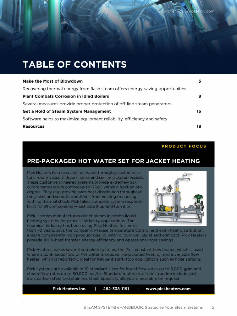
Pick Heaters help circulate hot water through jacketed reac-tors, rotary vacuum dryers, tanks and similar jacketed vessels. These custom-engineered systems provide extremely ac-curate temperature control up to 176oC within a fraction of a degree. They also provide even heat distribution throughout the jacket and smooth transitions from heating to cooling with no thermal shock. Pick takes complete system responsi-bility for all components — just pipe it up and turn it on.
Pick Heaters manufactures direct steam injection liquid heating systems for process industry applications. The chemical industry has been using Pick Heaters for more than 70 years, says the company. Precise temperature control and even heat distribution ensure consistently high product quality with no burn-on. Quiet and compact, Pick Heaters provide 100% heat transfer energy efficiency and operational cost savings.
Pick Heaters makes several complete systems: the Pick constant flow heater, which is used where a continuous flow of hot water is needed like jacketed heating, and a variable flow heater, which is reportedly ideal for frequent start/stop applications such as hose stations.
Pick systems are available in 10 standard sizes for liquid flow rates up to 5,000 gpm and steam flow rates up to 50,000 lbs./hr. Standard materials of construction include cast iron, carbon steel and stainless steel. Specialty alloys are available on request.
PRE-PACKAGED HOT WATER SET FOR JACKET HEATING
P R O D U C T F O C U S
Pick Heaters Inc. | 262-338-1191 | www.pickheaters.com
STEAM SYSTEMS eHANDBOOK: Strategize Your Steam Systems 3
AD INDEX
Armstrong International • www.armstronginternational.com . . . . . . . . . . . . . . . . . . . . . . . . . . . . . .4
Check-All Valve Mfg. Co. • www.epiccheckvalves.com . . . . . . . . . . . . . . . . . . . . . . . . . . . . . . . . . . . . 7
Pick Heaters Inc. • www.pickheaters.com . . . . . . . . . . . . . . . . . . . . . . . . . . . . . . . . . . . . . . . . . . . . . . . 14
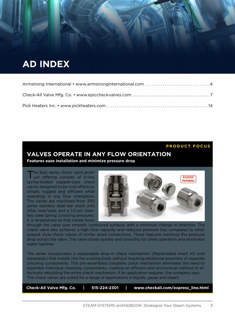
The Epic series check valve prod-uct offering consists of in-line
spring-loaded poppet-type check valves designed to be cost effective, simple, rugged and efficient while operating in any flow orientation. The valves are machined from 300 series stainless steel bar stock with Aflas seat/seals and a 1/2-psi stain-less steel spring (cracking pressure). It is streamlined so that media flows through the valve over smooth, contoured surfaces with a minimum change in direction. The check valve also achieves a high flow capacity and reduced pressure loss compared to other poppet style check valves of similar sized connections. These features minimize the pressure drop across the valve. The valve closes quickly and smoothly for silent operation and eliminates water hammer.
The series incorporates a replaceable drop-in check mechanism (Replaceable Insert Kit sold separately) that installs into the existing body without requiring additional assembly of separate checking components. This pre-assembled complete check mechanism eliminates the need to assemble individual checking components, creating an efficient and economical method of ef-fectively rebuilding the entire check mechanism, if an application requires, the company says.The check valves are suited for a range of applications in liquids, gases and steam.
VALVES OPERATE IN ANY FLOW ORIENTATION Features ease installation and minimize pressure drop
P R O D U C T F O C U S
Check-All Valve Mfg. Co. | 515-224-2301 | www.checkall.com/express_line.html

www.chemicalprocessing.com
STEAM SYSTEMS eHANDBOOK: Strategize Your Steam Systems 5
Irrespective of how steam is produced
in our process plants, several aspects
of steam generation are common; we
should apply standard best practices to
them. This column specifically addresses
the blowdown stream as well as both the
flash steam recovery and heat recovery that
we should implement in our steam systems.
Every steam system has a water treatment
plant; feedwater is made up of treated make-
up water, returned condensate and directly in-
jected steam (in the deaerator). Although the
condensate and steam are clean, the treated
makeup water still brings in dissolved impuri-
ties. Because these impurities are not soluble
in steam, they remain in the boiler. As a result,
their concentration builds and can lead to
serious operational problems such as scal-
ing on the water-side of the tubes resulting
in tube leaks and failures, foaming resulting
in liquid carryover, loose sludge in the boiler
water, etc. All of these problems could dam-
age boiler integrity. Blowdown is the primary
mechanism that controls the water chemistry
of the boiler water. It regulates the concentra-
tion of dissolved and precipitated chemicals in
the boiler and, thus, ensures steam generation
equipment functions reliably.
Generally, boiler water conductivity or total
dissolved solids is used to control blowdown,
but as our steam systems get more complex,
other parameters — pH, silica, iron, etc. —
also are used as secondary control points.
In the past 25 years, I have seen blowdown
rates as low as 1% and in some instances as
high as 15%. Blowdown rate depends on sev-
eral factors; however, I will not be covering
blowdown rate in this column. Please work
Make the Most of BlowdownRecovering thermal energy from flash steam offers energy-saving opportunities
By Riyaz Papar
www.chemicalprocessing.com
STEAM SYSTEMS eHANDBOOK: Strategize Your Steam Systems 6
with your water chemist to ensure you have
everything in place to minimize blowdown.
CAPTURE THERMAL ENERGY Blowdown, because it is saturated liquid
water at steam generation pressure, con-
tains a significant amount of thermal ener-
gy. The higher the steam generation pres-
sure, the higher the saturation (blowdown)
temperature and the higher the thermal
energy (Btu/lb) associated with the blow-
down. As blowdown is discharged from the
boiler, this thermal energy (provided by the
fuel or from another source) is lost. There-
fore, reducing the amount of blowdown to
the bare minimum is an excellent best prac-
tice; beyond that we need to look at other
mechanisms to capture lost energy.
So, that brings us to creating and recover-
ing flash steam from blowdown and then, if
economically justifiable, recovering heat from
the liquid water before discharge. The sim-
plest configuration is to first take the blow-
down stream into a flash tank whose pressure
is slightly higher than either the deaerator
pressure or the lowest-pressure steam header
in the steam generation area. The blowdown
flashes and produces low-pressure steam
that can be recovered and used within the
steam system to offset deaerator steam
demand. Recovering flash steam accounts for
65–70% of the total blowdown stream energy
that would otherwise have been lost. Inter-
estingly, the flash tank is a simple piece of
equipment with no moving parts. On several
occasions, I have been able to source it from
within a plant’s operations that are no longer
in service. The remainder of the liquid water
from the flash tank is still hot (>225°F) and
can be used to exchange heat in a simple
one-pass shell-and-tube heat exchanger or a
plate-and-frame unit, etc. This can be used to
heat the makeup water going to the deaera-
tor, thereby saving on overall steam demand
from utilities.
Also, I have faced some challenges in plants
when I tried implementing blowdown thermal
energy recovery. Most relate to past incorrect
applications, such as a large U-tube heat
exchanger used to recover heat from blow-
down that fouled and eventually was taken
out of service because it became a mainte-
nance headache. In other plants, because
there is so much excess low-pressure steam,
managers claim there’s no benefit of low-
pressure, low-temperature heat recovery. This
is not necessarily true; technologies exist to
upgrade low-pressure steam and make use of
every Btu that would otherwise be lost. I
realize the overall blowdown energy recovery
and cost savings may not be huge (<2%) but,
as one of the simplest and most cost-effective
best practices, it should never be ignored!
(For more on improving boiler management
to help save energy, see “Optimize Boiler
Loads,” http://goo.gl/z9c1M1 and “Don’t Get
Steamed,” http://goo.gl/xoUQSM.)
RIYAZ PAPAR is a former CP energy columnist. He can
be reached at [email protected].
The EPIC®
Check Valves Get Up To Steam
Manufactured in West Des Moines, Iowa, USA by Check-All Valve Mfg., Co.®
Check Valves With a World of Possibilities!
www.epiccheckvalves.com ♦ [email protected]
Pre-assembled Drop-in Replaceable Check Mechanism
Patent Pending
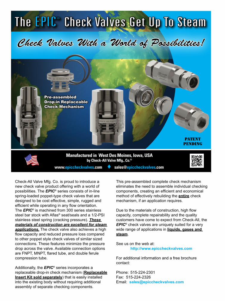
Check-All Valve Mfg. Co. is proud to introduce a new check valve product offering with a world of possibilities. The EPIC® series consists of in-line spring-loaded poppet-type check valves that are designed to be cost effective, simple, rugged and efficient while operating in any flow orientation. The EPIC® is machined from 300 series stainless steel bar stock with Aflas® seat/seals and a 1/2-PSI stainless steel spring (cracking pressure). These materials of construction are excellent for steam applications. The check valve also achieves a high flow capacity and reduced pressure loss compared to other poppet style check valves of similar sized connections. These features minimize the pressure drop across the valve. Available connection options are FNPT, MNPT, flared tube, and double ferule compression tube.
Additionally, the EPIC® series incorporates a replaceable drop-in check mechanism (Replaceable Insert Kit sold separately) that is easily installed into the existing body without requiring additional assembly of separate checking components.
This pre-assembled complete check mechanism eliminates the need to assemble individual checking components, creating an efficient and economical method of effectively rebuilding the entire check mechanism, if an application requires.
Due to the materials of construction, high flow capacity, complete repairability and the quality customers have come to expect from Check-All, the EPIC® check valves are uniquely suited for a very wide range of applications in liquids, gases and steam.
See us on the web at: http://www.epiccheckvalves.com
For additional information and a free brochure contact:
Phone: 515-224-2301Fax: 515-224-2326Email: [email protected]
www.chemicalprocessing.com
STEAM SYSTEMS eHANDBOOK: Strategize Your Steam Systems 8
Steam generation plays a critical role
at many industrial facilities. Unfor-
tunately, the high-temperature and
high-pressure environment of large steam
generators makes them susceptible to
corrosion. Even seemingly minor impurity
ingress can cause problems [1]. Fortunately,
plants can take advantage of a lot of les-
sons learned about preventing corrosion in
boilers. However, an often overlooked issue
is the risk of severe corrosion occurring dur-
ing those times when a steam generator is
down due to lack of steam demand or for
maintenance. This article outlines several
techniques for protecting steam generators
at these times. Our examples come from
a power plant, Lincoln Electric System’s
Terry Bundy Generating Station in Lincoln,
Nebraska, but the technologies suit process
plants as well.
BACKGROUNDThe Terry Bundy plant has three GE
LM6000 combustion turbines, two of which
are equipped with heat recovery steam
generators (HRSGs) that drive a supple-
mental steam turbine. Total plant capacity
is 170 MW. The units cycle on and off, often
on a daily basis during the summer, accord-
ing to the requirements of the South West
Power Pool. At other times, a unit may be
down for several days or perhaps even
weeks during periods of mild weather or for
maintenance outages.
For normal operating chemistry, the HRSG
feedwater is on an all-volatile treatment oxi-
dizing [AVT(O)] program, with ammonium
hydroxide injection to maintain feedwater
pH within a 9.6–10 range. High-pressure
evaporator chemistry complies with the
Plant Combats Corrosion in Idled Boilers Several measures provide proper protection of off-line steam generators
By Brad Buecker, Kiewit Engineering and Design Co., and Dan Dixon, Lincoln Electric System
www.chemicalprocessing.com
STEAM SYSTEMS eHANDBOOK: Strategize Your Steam Systems 9
Electric Power Research Institute’s phos-
phate guidelines, with trisodium phosphate
as the only phosphate species and control
within a 1–3 ppm range. The high-pressure
evaporator pH control range is 9.5–10. Free
caustic concentrations are maintained at or
below 1 ppm to minimize the risk of caustic
gouging.
For short-term outages, the HRSGs must
remain full of condensate to enable quick
startup. On the other hand, a maintenance
outage requires draining of the unit, prefer-
ably while it is hot so it flash-dries. How-
ever, even such drying still leaves some
areas exposed to moist conditions and,
thus, vulnerable unless additional protective
methods are used.
The equipment and processes outlined
below all are designed to protect the unit
from oxygen corrosion during any outage.
Oxygen attack is extremely serious.
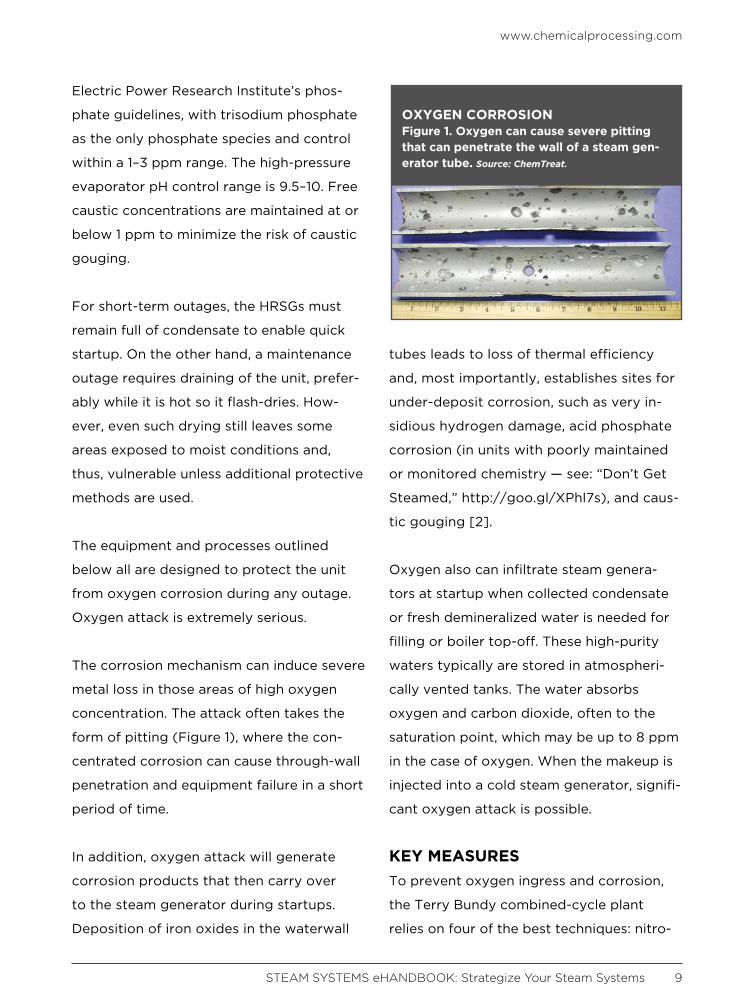
The corrosion mechanism can induce severe
metal loss in those areas of high oxygen
concentration. The attack often takes the
form of pitting (Figure 1), where the con-
centrated corrosion can cause through-wall
penetration and equipment failure in a short
period of time.
In addition, oxygen attack will generate
corrosion products that then carry over
to the steam generator during startups.
Deposition of iron oxides in the waterwall
tubes leads to loss of thermal efficiency
and, most importantly, establishes sites for
under-deposit corrosion, such as very in-
sidious hydrogen damage, acid phosphate
corrosion (in units with poorly maintained
or monitored chemistry — see: “Don’t Get
Steamed,” http://goo.gl/XPhl7s), and caus-
tic gouging [2].
Oxygen also can infiltrate steam genera-
tors at startup when collected condensate
or fresh demineralized water is needed for
filling or boiler top-off. These high-purity
waters typically are stored in atmospheri-
cally vented tanks. The water absorbs
oxygen and carbon dioxide, often to the
saturation point, which may be up to 8 ppm
in the case of oxygen. When the makeup is
injected into a cold steam generator, signifi-
cant oxygen attack is possible.
KEY MEASURESTo prevent oxygen ingress and corrosion,
the Terry Bundy combined-cycle plant
relies on four of the best techniques: nitro-
OXYGEN CORROSIONFigure 1. Oxygen can cause severe pitting that can penetrate the wall of a steam gen-erator tube. Source: ChemTreat.
www.chemicalprocessing.com
STEAM SYSTEMS eHANDBOOK: Strategize Your Steam Systems 10
gen blanketing; periodic water circulation;
dissolved oxygen removal from makeup
condensate and demineralized water; and
warm air recirculation to protect the low-
pressure turbine.
Nitrogen blanketing. The first and fore-
most measure is nitrogen blanketing dur-
ing shutdown and subsequent short-term
layups. Experience has shown that intro-
ducing nitrogen to key points in the system
before the pressure has totally decayed will
minimize ingress of air. Then, as the system
continues to cool, only nitrogen enters, not
oxygen-laden air. Key points for nitrogen
protection in HRSGs include the evaporator,
economizer and feedwater circuits.
The nitrogen blanketing system was in-
stalled in 2005, just a few years after the
steam generators’ startup, when plant
personnel discovered oxygen pitting in one
of the high-pressure evaporators as well as
other corrosion.
One question that often arises is how best
to supply nitrogen. Certainly local gas-sup-
ply or welding firms can provide bottles
of compressed nitrogen. Liquid nitrogen
is another possibility. Terry Bundy person-
nel selected a different method, nitrogen
generation via a pressure-swing adsorp-
tion (PSA) system. (For more on such
units for nitrogen generation, see: “Rethink
Nitrogen Supply for Chemical Blanketing,”
http://goo.gl/btiSw3.)
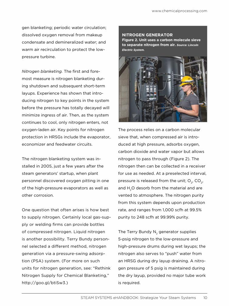
The process relies on a carbon molecular
sieve that, when compressed air is intro-
duced at high pressure, adsorbs oxygen,
carbon dioxide and water vapor but allows
nitrogen to pass through (Figure 2). The
nitrogen then can be collected in a receiver
for use as needed. At a preselected interval,
pressure is released from the unit; O2, CO2,
and H2O desorb from the material and are
vented to atmosphere. The nitrogen purity
from this system depends upon production
rate, and ranges from 1,000 scfh at 99.5%
purity to 248 scfh at 99.99% purity.
The Terry Bundy N2 generator supplies
5-psig nitrogen to the low-pressure and
high-pressure drums during wet layups; the
nitrogen also serves to “push” water from
an HRSG during dry layup draining. A nitro-
gen pressure of 5 psig is maintained during
the dry layup, provided no major tube work
is required.
NITROGEN GENERATORFigure 2. Unit uses a carbon molecule sieve to separate nitrogen from air. Source: Lincoln
Electric System.
www.chemicalprocessing.com
STEAM SYSTEMS eHANDBOOK: Strategize Your Steam Systems 11
An obvious major concern with nitrogen
blanketing — and why some plants don’t
use it — is safety. Nitrogen is an asphyxi-
ating agent and requires strict adherence
to confined-space entry procedures and
proper ventilation of the space.
Periodic water circulation. This is another
important point with regard to wet layup
chemistry. Regular water movement mini-
mizes stagnant conditions that can con-
centrate oxygen in localized areas to cause
pitting. Both Terry Bundy HRSGs have cir-
culating systems installed on the high- and
low-pressure circuits for use during wet
layups. Each circuit uses one of two redun-
dant preheater recirculation pumps, which
normally are in service during HRSG opera-
tion to mitigate acid dew point corrosion
of external circuits. Each pump provides
approximately 100 gpm per circuit. Valves
and piping have been added to enable
seamless transition from layup circula-
tion to normal operation. Sample/injection
systems allow operators to test the layup
chemistry for pH and dissolved oxygen
(using colorimetric ampules), and to inject
ammonium hydroxide if the pH must be
raised. In addition, modifications made in
each boiler drum permit the layup water to
bypass the drum baffle, promoting circu-
lation and minimizing short-circuiting via
the downcomers. The pumps typically are
started once drum pressure drops below
50 psig, and remain in service for the dura-
tion of the layup.
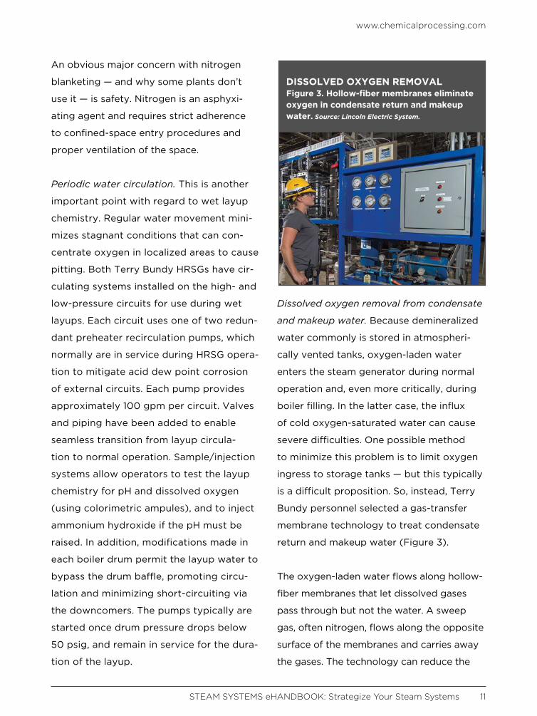
Dissolved oxygen removal from condensate
and makeup water. Because demineralized
water commonly is stored in atmospheri-
cally vented tanks, oxygen-laden water
enters the steam generator during normal
operation and, even more critically, during
boiler filling. In the latter case, the influx
of cold oxygen-saturated water can cause
severe difficulties. One possible method
to minimize this problem is to limit oxygen
ingress to storage tanks — but this typically
is a difficult proposition. So, instead, Terry
Bundy personnel selected a gas-transfer
membrane technology to treat condensate
return and makeup water (Figure 3).
The oxygen-laden water flows along hollow-
fiber membranes that let dissolved gases
pass through but not the water. A sweep
gas, often nitrogen, flows along the opposite
surface of the membranes and carries away
the gases. The technology can reduce the
DISSOLVED OXYGEN REMOVALFigure 3. Hollow-fiber membranes eliminate oxygen in condensate return and makeup water. Source: Lincoln Electric System.

www.chemicalprocessing.com
STEAM SYSTEMS eHANDBOOK: Strategize Your Steam Systems 12
dissolved oxygen concentration from satu-
rated conditions to less than 10 ppb.
DON’T FORGET THE STEAM TURBINEFar too often in the power industry, plants
allow the condenser hotwell to remain
moist or even contain standing water dur-
ing outages in which the condenser vacuum
was broken and air entered the condenser
and low-pressure turbine. The low-pressure
blades in steam turbines typically collect
salts that carry over with steam from boiler
drums. The combination of a moisture-laden
atmosphere and these salt deposits can fos-
ter pitting and stress corrosion cracking.
A very practical method to combat this cor-
rosion, and the one adopted at Terry Bundy,
is injection of desiccated air into the condens-
er during all but short-term, i.e., <72 h, layups.
This system uses a desiccant wheel dehu-
RELATED CONTENT ON CHEMICALPROCESSING.COM“Don’t Get Steamed,” http://goo.gl/XPhl7s
“Keep Out of Hot Water,” http://goo.gl/LFlVig
“Rethink Nitrogen Supply for Chemical Blanketing,” http://goo.gl/btiSw3
“Plants Pit New Tools Against Corrosion,” http://goo.gl/T2Vqj3
“Should You Revamp or Replace Your Boiler?,” http://goo.gl/5aahSG
DEHUMIDIFIERFigure 4. Desiccant wheel unit provides air with only 10% humidity to condenser and low-pressure turbine. Source: Lincoln Electric System.
www.chemicalprocessing.com
STEAM SYSTEMS eHANDBOOK: Strategize Your Steam Systems 13
midifier (Figure 4) to provide 700 scfm of
100°F air at 10% humidity to the condenser
and low-pressure turbine. This flow can low-
er the relative humidity from nearly 100% to
less than 30% in just a few hours.
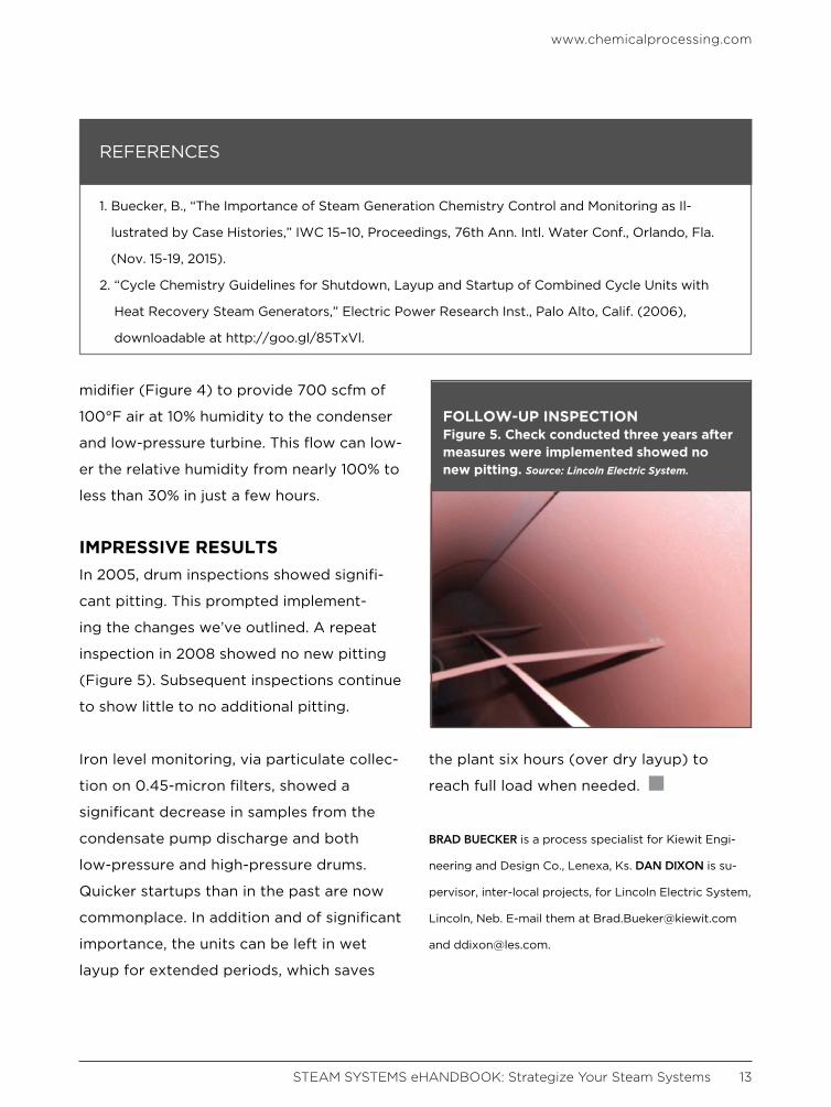
IMPRESSIVE RESULTSIn 2005, drum inspections showed signifi-
cant pitting. This prompted implement-
ing the changes we’ve outlined. A repeat
inspection in 2008 showed no new pitting
(Figure 5). Subsequent inspections continue
to show little to no additional pitting.
Iron level monitoring, via particulate collec-
tion on 0.45-micron filters, showed a
significant decrease in samples from the
condensate pump discharge and both
low-pressure and high-pressure drums.
Quicker startups than in the past are now
commonplace. In addition and of significant
importance, the units can be left in wet
layup for extended periods, which saves
the plant six hours (over dry layup) to
reach full load when needed.
BRAD BUECKER is a process specialist for Kiewit Engi-
neering and Design Co., Lenexa, Ks. DAN DIXON is su-
pervisor, inter-local projects, for Lincoln Electric System,
Lincoln, Neb. E-mail them at [email protected]
and [email protected].
REFERENCES
1. Buecker, B., “The Importance of Steam Generation Chemistry Control and Monitoring as Il-
lustrated by Case Histories,” IWC 15–10, Proceedings, 76th Ann. Intl. Water Conf., Orlando, Fla.
(Nov. 15-19, 2015).
2. “Cycle Chemistry Guidelines for Shutdown, Layup and Startup of Combined Cycle Units with
Heat Recovery Steam Generators,” Electric Power Research Inst., Palo Alto, Calif. (2006),
downloadable at http://goo.gl/85TxVl.
FOLLOW-UP INSPECTIONFigure 5. Check conducted three years after measures were implemented showed no new pitting. Source: Lincoln Electric System.

LARRY SCHUBERT FLAT LINED!
Actually, the first thing he felt was relieved. Because Larry finally discovered absolute precision temperature control for all his chemical processing. Thanks to Pick Direct Steam Injection Heaters, now his process temperature graphs show one, long, beautiful, flat line. That’s because Pick’s exceptional temperature control automatically holds discharge temperatures to extremely close tolerances – within 1°C or less, while providing rapid response to changing process conditions.
Whether you require jacketed heating or other process liquid heating applications, Pick eliminates BTU losses for 100% energy efficiency. This alone could save Larry’s company up to 20% in fuel costs. In addition, Pick’s compact design along with its ease of maintenance, saves valuable space and invaluable down time. All this, combined with an unlimited supply of hot water, low water pressure drop, the lowest OSHA noise level, and the widest operating range of any direct steam injection heater is enough to make anyone’s heart go pit-a-pat. Which is precisely what flat lining can do to a guy.
thing he felt was relieved. Because Larry finally discovered absolute precision
(and feels like a million bucks...)
®
262.338.1191E-mail: [email protected]
www.chemicalprocessing.com
STEAM SYSTEMS eHANDBOOK: Strategize Your Steam Systems 15
Refineries and other chemical
plants frequently miss or have
a delayed response to critical
issues in daily operations due to failed
steam traps. However, failed steam traps
are often viewed as a routine part of run-
ning a plant or the cost of production.
While steam traps play a crucial role in
plantwide safety, equipment reliability
and product quality, they also can cause
production interruptions if not maintained
properly.
STEAM SYSTEM CHALLENGESRefineries often experience daily issues
due to a lack of steam system and steam
trap management. Some of the problems
encountered include:
• Injuries and incidents related to steam
tracing
• Escalating repair costs
• Increasing unit freeze-up issues
• The inability to distinguish easily between
working and nonworking steam traps
• The inability to generate work lists for
repairs resulting from an incomplete
database
• Inappropriate or insufficient repair tracking
Steam trap management can be a cum-
bersome task for refineries that house
2,000 to 10,000 traps, so the ability to
manage steam traps while generating data
collection is advantageous. Without a
steam system management tool, refineries
are unable to generate reports for failed
traps or seasonal shutoffs or provide
reports by area or site. They also have no
access to consistent information in real
time.
Get a Hold of Steam System ManagementSoftware helps to maximize equipment reliability, efficiency and safety

www.chemicalprocessing.com
STEAM SYSTEMS eHANDBOOK: Strategize Your Steam Systems 16
Steam system monitoring software can
help refineries keep a close eye on their
steam traps. The software uses algorithms
to analyze steam trap data to track be-
havior and performance for steam system
management. It tests, records, tracks and
reports on plant steam systems so that
refineries and other chemical plants can
manage multiple sites and various steam
trap types while decreasing the overall
time required for data collection, record-
ing and reporting.
MONITORING STEAM TRAPSTo address such issues, a U.S. refinery
with a capacity of 125,000 bbl/d of crude
oil turned to Sage for help with managing
9,010 steam traps. Within the first six to
eight months of starting the program, the
refinery documented savings of more than
$5 million as well as reductions in energy
and steam costs.
The software is designed to be intuitive
to use and easily accessible by an exclu-
sive mobile app (Figure 1). It offers tight
security, instant notifications and precise
documentation and can accommodate
companies of any size. It allows refineries
to increase equipment reliability, efficien-
cy and safety, while enabling reductions in
environmental emissions. Reports gener-
ated provide a totalized summary of se-
lected data in any of the following catego-
ries: monetary loss, fuel used, repair cost,
payback period, and CO2 emissions.
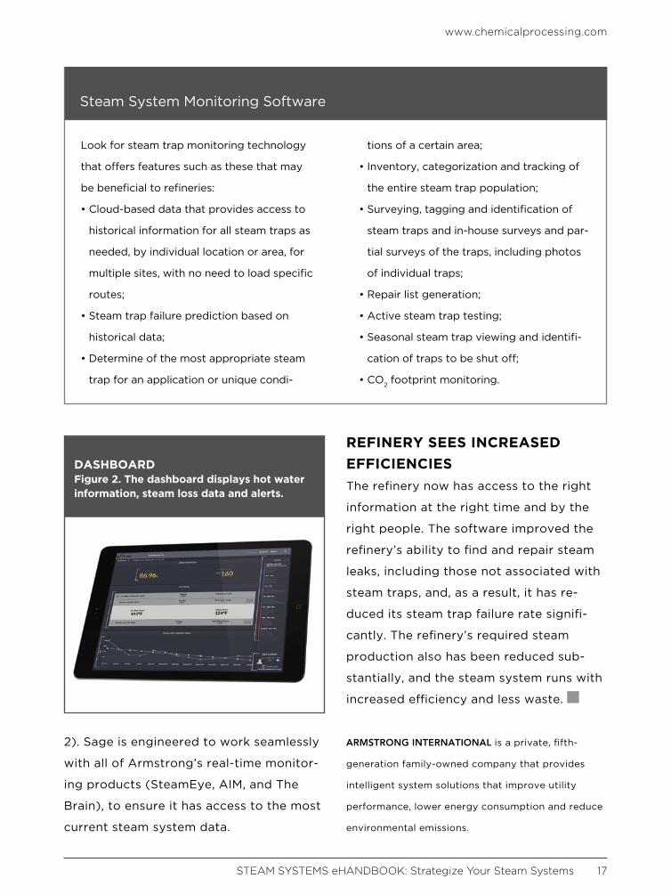
The software’s Team System, provides
a facility summary of steam trap system
performance rate and daily losses. It also
alerts users with system notifications that
allow for easy identification of problems
and maintenance of equipment. It also
shows annual steam loss — a 12-month
view of steam and monetary loss (Figure
MOBILE APPFigure 1. Steam system management can be carried out from the palm of your hand. This screen shows which traps have been tested along with pictures and trap conditions.
www.chemicalprocessing.com
STEAM SYSTEMS eHANDBOOK: Strategize Your Steam Systems 17
2). Sage is engineered to work seamlessly
with all of Armstrong’s real-time monitor-
ing products (SteamEye, AIM, and The
Brain), to ensure it has access to the most
current steam system data.
REFINERY SEES INCREASED EFFICIENCIESThe refinery now has access to the right
information at the right time and by the
right people. The software improved the
refinery’s ability to find and repair steam
leaks, including those not associated with
steam traps, and, as a result, it has re-
duced its steam trap failure rate signifi-
cantly. The refinery’s required steam
production also has been reduced sub-
stantially, and the steam system runs with
increased efficiency and less waste.
ARMSTRONG INTERNATIONAL is a private, fifth-
generation family-owned company that provides
intelligent system solutions that improve utility
performance, lower energy consumption and reduce
environmental emissions.
DASHBOARDFigure 2. The dashboard displays hot water information, steam loss data and alerts.
Look for steam trap monitoring technology
that offers features such as these that may
be beneficial to refineries:
• Cloud-based data that provides access to
historical information for all steam traps as
needed, by individual location or area, for
multiple sites, with no need to load specific
routes;
• Steam trap failure prediction based on
historical data;
• Determine of the most appropriate steam
trap for an application or unique condi-
tions of a certain area;
• Inventory, categorization and tracking of
the entire steam trap population;
• Surveying, tagging and identification of
steam traps and in-house surveys and par-
tial surveys of the traps, including photos
of individual traps;
• Repair list generation;
• Active steam trap testing;
• Seasonal steam trap viewing and identifi-
cation of traps to be shut off;
• CO2 footprint monitoring.
Steam System Monitoring Software
Visit the lighter side, featuring draw-
ings by award-winning cartoonist
Jerry King. Click on an image and you
will arrive at a page with the winning
caption and all submissions for that
particular cartoon.
JOIN US ON SOCIAL MEDIA!
ADDITIONAL RESOURCESEHANDBOOKSCheck out our vast library of past eHandbooks that offer a
wealth of information on a single topic, aimed at providing
best practices, key trends, developments and successful
applications to help make your facilities as efficient, safe,
environmentally friendly and economically competitive as
possible.
UPCOMING AND ON DEMAND WEBINARSTap into expert knowledge. Chemical Processing editors
and industry experts delve into hot topics challenging the
chemical processing industry today while providing in-
sights and practical guidance. Each of these free webinars
feature a live Q&A session and lasts 60 minutes.
WHITE PAPERSCheck out our library of white papers covering myriad top-
ics and offering valuable insight into products and solu-
tions important to chemical processing professionals. From
automation to fluid handling, separations technologies and
utilities, this white paper library has it all.
MINUTE CLINICChemical Processing’s Minute Clinic podcast series is de-
signed to tackle one critical issue at a time — giving you
hard-hitting information in just minutes.
ASK THE EXPERTSHave a question on a technical issue that needs to be ad-
dressed? Visit our Ask the Experts forum. Covering topics
from combustion to steam systems, our roster of leading
subject matter experts, as well as other forum members,
can help you tackle plant issues.
TOP COMICAL PROCESSING
STEAM SYSTEMS eHANDBOOK: Strategize Your Steam Systems 18