Stückliste - Altecare
19
+++ construction manual SR 71 Blackbird (EDF Version) from JetCom +++ Table of content: Page List of material and overview of provided frames 3 Mounting of main gear 4 Mounting of nose gear 5 Mounting of elevons 6 Installation of the rudders 7 Mounting of the rudders 9 Installation of the servos 10 Installation of the EDF 11 Installation of the battery 15 Suggestion for the installation of the interior equipment 16 Centre of gravity and throws 20 Recommended accessories 20 Spare parts 20 Page 2 of 20 EDF version 1.0
Transcript of Stückliste - Altecare

+++ construction manual SR 71 Blackbird (EDF Version) from JetCom +++
Table of content:
Page List of material and overview of provided frames 3
Mounting of main gear 4
Mounting of nose gear 5
Mounting of elevons 6
Installation of the rudders 7
Mounting of the rudders 9
Installation of the servos 10
Installation of the EDF 11
Installation of the battery 15
Suggestion for the installation of the interior equipment 16
Centre of gravity and throws 20
Recommended accessories 20
Spare parts 20
Page 2 of 20 EDF version 1.0

+++ construction manual SR 71 Blackbird (EDF Version) from JetCom +++
List of material: Part no. Material Application 1+2 6 mm multiple bonded
plywood Main gear mount point
3 6 mm multiple bonded plywood
Nose gear mount point
4* -------------- --------------------- 5 Poplar plywood Servo mounting frame 6* -------------- --------------------- 7+8 Plastic molding Servo covering 9 Carbon sticks Rudder fixing 10+11 Composite Intake rings * applicable only for turbine version Overview of provided frames*:
1 23
4 4
5 5
5 56 6
7 8
99 99
*Frames no. 4 and 6 are applicable only for the turbine version and will not be included in delivery of the EDF version.
Page 3 of 20 EDF version 1.0

+++ construction manual SR 71 Blackbird (EDF Version) from JetCom +++
Mounting of main gear The landing gear compartment frames are already laminated. The centre of the retract plate is located as shown in the picture below.
The cut-outs need to be 46 mm x 36 mm and be made on the bottom of each wing half.
Please ensure the cut-outs do not exceed the size given above to avoid damaging the retract plate frames. Trial fit the retract plates into the retract frames already glued in the wing. Use Hysol epoxy or similar to glue the mounting plates into position. Make sure the retracts are 90 degrees to the fuselage, to ensure a proper working retract later on.
Page 4 of 20 EDF version 1.0
+++ construction manual SR 71 Blackbird (EDF Version) from JetCom +++
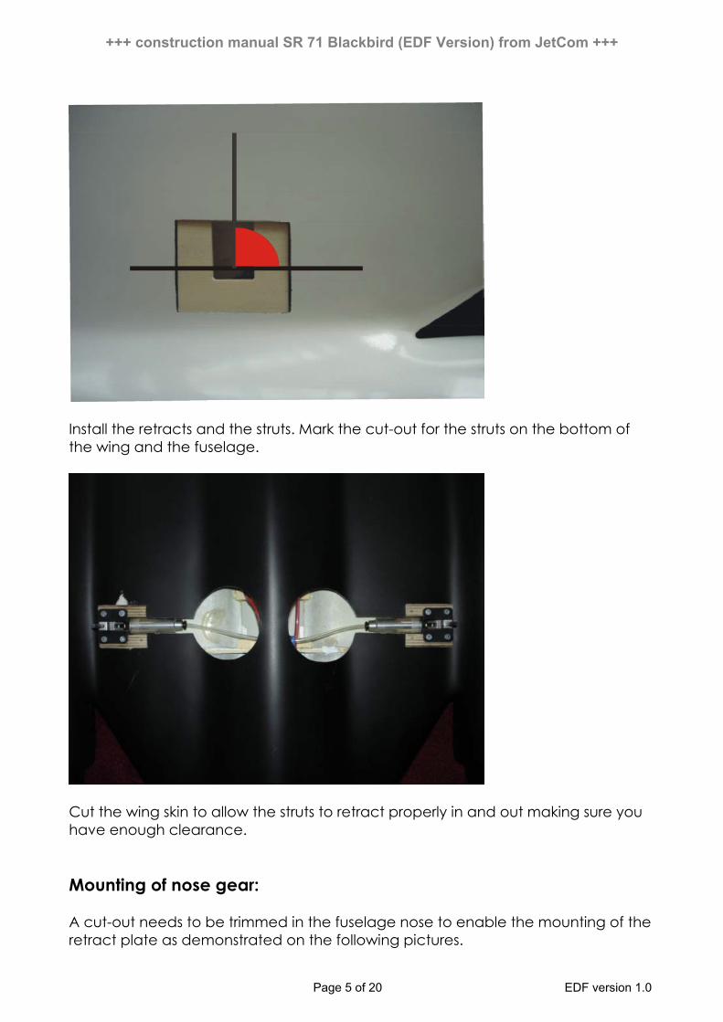
Install the retracts and the struts. Mark the cut-out for the struts on the bottom of the wing and the fuselage.
Cut the wing skin to allow the struts to retract properly in and out making sure you have enough clearance. Mounting of nose gear: A cut-out needs to be trimmed in the fuselage nose to enable the mounting of the retract plate as demonstrated on the following pictures.
Page 5 of 20 EDF version 1.0

+++ construction manual SR 71 Blackbird (EDF Version) from JetCom +++
Afterwards fit the retract plate into the U-shaped milling of the compartment frame. Please make sure the retract runs parallel with the fuselage to allow the strut to retract properly in and out. Furthermore you need to provide a cut-out on frame no 3 for the gear cylinder. Install the retract and the strut including the wheel. Cut the fuselage skin according to the size of the nose gear making sure you have enough clearance. Mounting of elevons Mark and cut 3 hinge locations in each of the elevons making sure they are well spaced out. The wing and elevons have balsa inserts to accommodate the hinges.
Glue the hinges in place using good quality epoxy or equivalent. Be careful that the joints of the hinges keep free of epoxy (if necessary bedabble them with some oil or silicon) to ensure their flexibility. For safety reasons we recommend to dowel the hinges additionally, so that they are unable to loosen while flying. Therefore you need to drill a 2 mm hole through the wing and the elevons at each position a hinge is located. Afterwards you can fix it by gluing a shortened toothpick in the holes. Finally you only need to grind overlapping parts of the toothpick smoothly with the wing respective the elevons.
Page 6 of 20 EDF version 1.0

+++ construction manual SR 71 Blackbird (EDF Version) from JetCom +++
Installation of the rudders The functional installation of the rudder does not support the flight qualities. However, to follow specific requirements the rudders can be installed functional as follows: You need to cut the rudder as shown in the pictures below.
A balsa structure frame is provided inside the rudder. This frame is located in the middle of the saw kerf for fixing the hinges. To allow mobility you need to add a piece of balsa wood at the front of the rudder. Afterwards the balsa should be tapered by grinding it.
Now you need to glue the hinges in the front of both parts of the rudder.
Page 7 of 20 EDF version 1.0

+++ construction manual SR 71 Blackbird (EDF Version) from JetCom +++
The rudder servo is located in the rudder. A servo mounting plate and a servo covering fitting for a Hitec HS 125 MG or equivalent is provided in the kit. Using a razor saw, cut the skin of the rudder to accommodate the servo and the servo tray. The size of the cut-out can be found on the picture below.
Now you can glue the servo tray into the rudder. Afterwards you can fix the servo. The servo and the rudder are connected by a 2 mm connecting rod, which is fixed by a rudder horn as demonstrated on the next picture.
Page 8 of 20 EDF version 1.0

+++ construction manual SR 71 Blackbird (EDF Version) from JetCom +++
Finally you should fix the servo covering and trial fit the rudder on the model.
For the second rudder you should go ahead like you did for the first, only side –inverted. For optical reasons, we recommend to locate the servos on the inner side of the rudder. Mounting of the rudders The rudders are connected with the fuselage by using the provided 6 mm carbon rods. Roughen the carbon rods carefully. Than you can glue the carbon rods in place by using good quality epoxy or equivalent.
Page 9 of 20 EDF version 1.0

+++ construction manual SR 71 Blackbird (EDF Version) from JetCom +++
Afterwards roughen the installation face of the rudder and on the fuselage carefully. Now you can glue the rudder onto the fuselage. Eventually bulging out epoxy should be removed immediately. For a smooth transition you can flatten the gap with smoothing cement. Installation of the servos On the bottom of the fuselage cut-outs for the servo plates need to be provided. The picture below shows you the center of the servo mount location.
The cut-outs need to be 43 mm x 43 mm. Use Hysol or similar epoxy to glue the mount plate into the cut-out. Once the epoxy is dry you can fix the servo. To connect the elevon with the servo, the servo rod needs to be fixed with a rudder horn.
Page 10 of 20 EDF version 1.0

+++ construction manual SR 71 Blackbird (EDF Version) from JetCom +++
After connecting the elevons with the servos, you should adjust the deflection (see page 19 of the manual). Last but not least the servo covering should be fixed. Please pay attention that the servos keep functional afterwards. Installation of the EDF The following specifications are belonging to the use of the Schuebeler DS-30-DIA 3-ph EDFs. On all air intakes, the short and the long ones, a 1 mm balsa layer needs to be glued at the reinforced end of the tubes by using good quality epoxy. The direction of the fibres should be parallel to the axis of the tube. Once the epoxy is dry, add a thin layer of plywood to the balsa. The plywood should overlap the tubes, to allow a pipe coupling.
Page 11 of 20 EDF version 1.0

+++ construction manual SR 71 Blackbird (EDF Version) from JetCom +++
After you have prepared all air intakes as described, you can go ahead assembling the tubes and the EDFs as demonstrated on the following pictures:
The tubes will be affixed on the EDF by using adhesive tape that is wrapped around the EDF and the pipe coupling.
Page 12 of 20 EDF version 1.0

+++ construction manual SR 71 Blackbird (EDF Version) from JetCom +++
Now you can implement the EDF units in the gondolas. This should be done from the back of the model. When doing so, please pay attention not to deviate the cables. Even though the EDF units should fit closely, it should not be difficult to implement them. Adjust the inner diameter of the structure frames if necessary.
The tubes should be overlapping in the front of the gondolas.
It is important that the EDF units are mounted aligned in the gondolas. It should neither show angular distortion nor side trust. Now the intake rings should be affixed with Hysol or similar epoxy on the edge of the tubes and the front of the gondolas as shown on the next picture.
Page 13 of 20 EDF version 1.0

+++ construction manual SR 71 Blackbird (EDF Version) from JetCom +++
At the outlet the tubes can be fixed with a 1 mm balsa layer. If necessary add a plywood layer in addition. After fixing the tubes in the gondolas like this glue it with Hysol or equivalent.
Page 14 of 20 EDF version 1.0

+++ construction manual SR 71 Blackbird (EDF Version) from JetCom +++
Installation of the battery The battery must be placed in the center of gravity (see page 19 of the manual). Ensure that they are not able to move during the flight (e.g. by fixing them with Velcro).
Page 15 of 20 EDF version 1.0

+++ construction manual SR 71 Blackbird (EDF Version) from JetCom +++
Suggestion for the installation of the interior equipment It is always a matter of individual preference on where to install the various electronic components, receiver, battery and so on. The pictures below show the installation we have used for our model.
Page 16 of 20 EDF version 1.0

+++ construction manual SR 71 Blackbird (EDF Version) from JetCom +++
Page 17 of 20 EDF version 1.0

+++ construction manual SR 71 Blackbird (EDF Version) from JetCom +++
Page 18 of 20 EDF version 1.0

+++ construction manual SR 71 Blackbird (EDF Version) from JetCom +++
Page 19 of 20 EDF version 1.0

+++ construction manual SR 71 Blackbird (EDF Version) from JetCom +++
Page 20 of 20 EDF version 1.0
Center of gravity and throws The center of gravity is located 510 mm measured forward from the end of the fuselage. For stable flight quality we strongly recommend not to vary this default!
Aileron deflection: inner ones +– 30 mm; outer ones +15 mm –20 mm Elevator deflection: inner ones +– 25 mm; outer ones +15 mm –20 mm Outer elevons: approx. 10 mm up Recommended accessories:
• Eurokit retract “small 3 kg” or EJF 3 gear air retract set “low profile” • Main gear: WaBo struts “SR-71”; nose gear: Eurokit CAR/15082/000 • INTAIRCO wheels and brakes No. IAC 1000 (diameter: 57 mm main and nose
wheels) • EDF: 2x Schübeler DS-30-Dia 3-ph • Motor: 2x Hacker B40-13S • Controller: 2x Hacker MASTER 40-O-flight • Servos: HS 5125 MG or HS 125 MG (Elevon and Rudder) • 2 x Mini servos (only if mechanically retract valve and brakes are used) • air intakes: Wemotec 2x MF-R4 and 1x MF-R2
Spare parts: Rudder set Order No.: SR71-001 Elevon set (inner and outer ones) Order No.: SR71-002 Canopy Order No.: SR71-003 Air intakes Order No.: SR71 004 Frames set Order No.: SR71-005
Last update: March 2006