
Status of SESAME Project - KEKepaper.kek.jp/PAC2009/papers/we5rfp022.pdf · STATUS OF SESAME...
3
STATUS OF SESAME PROJECT Amor Nadji, Thaer Abou-Hanieh, Ahed Aladwan, Mohammad Alnajdawi, Adel Amro, Maher Attal, Saed Budair, Darweech Foudeh, Adli Hamad, Tasaddaq Ali Khan, Arash Kaftoosian, Firas Makahleh, Salman Matalgah, Muayyed Sbahi, Maher Shehab, Hamed Tarawneh, Seadat Varnasseri, SESAME, P.O. Box 7, Allan 19252, Jordan Abstract Further steps have been last through for the SESAME machine. The installation of the Microtron was completed before the “soft” inauguration of 3rd November 2008 and all the related subsystems tests are now successfully finished. The Booster injection magnets power supplies are under test and the Booster main magnets power supplies are under tendering process. The new repetition rate of the Booster is 1 Hz. The magnetic study of the Storage Ring magnets has been updated using 3D calculation. The Storage Ring vacuum system has been also updated after adding two BPMs in each straight section. Consequently, the study of the interface between the girder, the magnets and the vacuum chamber has been revisited. INTRODUCTION SESAME (Synchrotron-light for Experimental Science and Application in the Middle East) is a 3 rd synchrotron radiation source under construction in Jordan [1]. The injector part consists of a 22.5 MeV Microtron and 800 MeV Booster which is the old retired BESSY 1 injector. The 2.5 GeV Storage Ring will be completely new. The beam emittance is 26 nm.rad and 12 straight sections are available for Insertion Devices. The phase 1 scientific program has been finalized and it is foreseen 7 beamlines from IR to hard X-rays. MICROTRON STATUS Since last EPAC [2], the Microtron system has been transferred from the temporary hangar and installed in its final position in the experimental hall, as can be seen from Fig. 1, were all the corresponding racks and subsystems have been reconnected according to the dismantling code given by BESSY which has been translated into a connection plan. The Microtron has been connected to a temporary chiller for the purpose of cooling till it will be integrated into the total cooling system of the SESAME machine. The correct reconnection has been verified by operating the Microtron system from its corresponding racks using the old PLC and the existing interlock logic. After detecting and treating some vacuum leaks, and using new vacuum turbo molecular pumps (two with 500 l/s and one with 150 l/s capabilities), a vacuum pressure of 3 x 10 -7 mbar has been achieved. In addition, a problem in the auxiliary gun control circuit has been fixed. This allowed us to operate the modulator at its normal operation mode and to test its performance by measuring its two outputs 9 kV, 4 μs voltage pulses. Figure 1: The BESSY I Microtron installed in the SESAME experimental hall. After being amplified, one of the two pulses is fed to the main electron gun with 63 kV amplitude and the other is fed to the magnetron with 45 kV amplitude. Figure 2 shows the measured pulses here at SESAME compared to what was measured at BESSY during the Microtron operation. Figure 2: (a) and (c) show the magnetron current and the main gun respectively as measured at SESAME. (b) and (d) show the same pulses as measured at BESSY I. The above measurements have been done without magnetic field (i.e. with the main magnet off) in order not to have any potential acceleration for any electron beam that could be produced. That was due to the unavailability of the shielding wall yet. According to the results that have been achieved, we believe that the Microtron is ready now for commissioning with beam. As the main shielding is not yet available, it has been decided to start the commissioning of the Microtron at the minimum extractable energy of ~ 5 MeV, using a temporary a) c) b) d) Proceedings of PAC09, Vancouver, BC, Canada WE5RFP022 Light Sources and FELs A05 - Synchrotron Radiation Facilities 2315
Transcript of Status of SESAME Project - KEKepaper.kek.jp/PAC2009/papers/we5rfp022.pdf · STATUS OF SESAME...
STATUS OF SESAME PROJECT
Amor Nadji, Thaer Abou-Hanieh, Ahed Aladwan, Mohammad Alnajdawi, Adel Amro, Maher Attal, Saed Budair, Darweech Foudeh, Adli Hamad, Tasaddaq Ali Khan, Arash Kaftoosian, Firas
Makahleh, Salman Matalgah, Muayyed Sbahi, Maher Shehab, Hamed Tarawneh, Seadat Varnasseri, SESAME, P.O. Box 7, Allan 19252, Jordan
Abstract Further steps have been last through for the SESAME
machine. The installation of the Microtron was completed before the “soft” inauguration of 3rd November 2008 and all the related subsystems tests are now successfully finished. The Booster injection magnets power supplies are under test and the Booster main magnets power supplies are under tendering process. The new repetition rate of the Booster is 1 Hz. The magnetic study of the Storage Ring magnets has been updated using 3D calculation. The Storage Ring vacuum system has been also updated after adding two BPMs in each straight section. Consequently, the study of the interface between the girder, the magnets and the vacuum chamber has been revisited.
INTRODUCTION SESAME (Synchrotron-light for Experimental Science
and Application in the Middle East) is a 3rd synchrotron radiation source under construction in Jordan [1]. The injector part consists of a 22.5 MeV Microtron and 800 MeV Booster which is the old retired BESSY 1 injector. The 2.5 GeV Storage Ring will be completely new. The beam emittance is 26 nm.rad and 12 straight sections are available for Insertion Devices. The phase 1 scientific program has been finalized and it is foreseen 7 beamlines from IR to hard X-rays.
MICROTRON STATUS Since last EPAC [2], the Microtron system has been
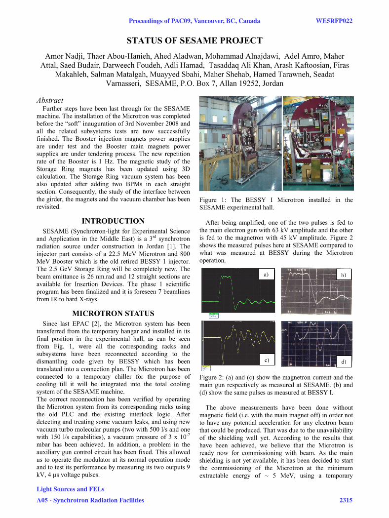
transferred from the temporary hangar and installed in its final position in the experimental hall, as can be seen from Fig. 1, were all the corresponding racks and subsystems have been reconnected according to the dismantling code given by BESSY which has been translated into a connection plan. The Microtron has been connected to a temporary chiller for the purpose of cooling till it will be integrated into the total cooling system of the SESAME machine. The correct reconnection has been verified by operating the Microtron system from its corresponding racks using the old PLC and the existing interlock logic. After detecting and treating some vacuum leaks, and using new vacuum turbo molecular pumps (two with 500 l/s and one with 150 l/s capabilities), a vacuum pressure of 3 x 10⁻⁷
mbar has been achieved. In addition, a problem in the auxiliary gun control circuit has been fixed. This allowed us to operate the modulator at its normal operation mode and to test its performance by measuring its two outputs 9 kV, 4 µs voltage pulses.
Figure 1: The BESSY I Microtron installed in the SESAME experimental hall.
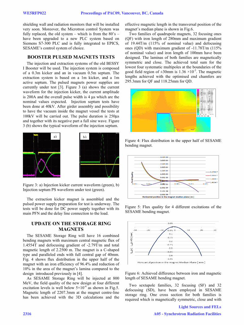
After being amplified, one of the two pulses is fed to the main electron gun with 63 kV amplitude and the other is fed to the magnetron with 45 kV amplitude. Figure 2 shows the measured pulses here at SESAME compared to what was measured at BESSY during the Microtron operation.
Figure 2: (a) and (c) show the magnetron current and the main gun respectively as measured at SESAME. (b) and (d) show the same pulses as measured at BESSY I.
The above measurements have been done without magnetic field (i.e. with the main magnet off) in order not to have any potential acceleration for any electron beam that could be produced. That was due to the unavailability of the shielding wall yet. According to the results that have been achieved, we believe that the Microtron is ready now for commissioning with beam. As the main shielding is not yet available, it has been decided to start the commissioning of the Microtron at the minimum extractable energy of ~ 5 MeV, using a temporary
a)
c)
b)
d)
Proceedings of PAC09, Vancouver, BC, Canada WE5RFP022
Light Sources and FELs
A05 - Synchrotron Radiation Facilities 2315
shielding wall and radiation monitors that will be installed very soon. Moreover, the Microtron control System was fully replaced, the old system – which is from the 80’s – have been upgraded to a new PLC system based on Siemens S7-300 PLC and is fully integrated to EPICS, SESAME’s control system of choice.
BOOSTER PULSED MAGNETS TESTS The injection and extraction systems of the old BESSY
I Booster will be used. The injection system is composed of a 0.3m kicker and an in vacuum 0.5m septum. The extraction system is based on a 1m kicker, and a 1m active septum. The pulsed magnets power supplies are currently under test [3]. Figure 3 (a) shows the current waveform for the injection kicker, the current amplitude is 200A and the overall pulse width is 4 μs which are the nominal values expected. Injection septum tests have been done at 40kV. After girder assembly and possibility to have the vacuum inside the magnet vessel the tests at 100kV will be carried out. The pulse duration is 250μs and together with its negative part a full sine wave. Figure 3 (b) shows the typical waveform of the injection septum.
Figure 3: a) Injection kicker current waveform (green), b) Injection septum PS waveform under test (green).
The extraction kicker magnet is assembled and the pulsed power supply preparation for test is underway. The tests will be done for DC power supply together with its main PFN and the delay line connection to the load.
UPDATE ON THE STORAGE RING MAGNETS
The SESAME Storage Ring will have 16 combined bending magnets with maximum central magnetic flux of 1.4554T and defocusing gradient of -2.79T/m and total magnetic length of 2.2500 m. The magnet is a C-shaped type and paralleled ends with full central gap of 40mm. Fig. 4 shows flux distribution in the upper half of the magnet with an iron efficiency of 96.4% and reduction of 10% in the area of the magnet’s lamina compared to the design introduced previously in [4].
As SESAME Storage Ring will be injected at 800 MeV, the field quality of the new design at four different excitation levels is well below 5×10⁻⁴ as shown in Fig.5. Magnetic length of 2207.3mm at the magnet centre-line has been achieved with the 3D calculations and the
effective magnetic length in the transversal position of the magnet’s median plane is shown in Fig.6.
Two families of quadrupole magnets, 32 focusing ones (QF) with iron length of 280mm and maximum gradient of 19.44T/m (115% of nominal value) and defocusing ones (QD) with maximum gradient of -11.78T/m (115% of nominal value) and iron length of 100mm have been designed. The laminas of both families are magnetically symmetric and close. The achieved total sum for the lowest four systematic multipoles at the boundaries of the good field region of ±30mm is 1.36 ×10⁻³. The magnetic lengths achieved with the optimised end chamfers are 295.3mm for QF and 118.25mm for QD.
Figure 4: Flux distribution in the upper half of SESAME bending magnet.
Figure 5: Flux quality for 4 different excitations of the SESAME bending magnet.
Figure 6: Achieved difference between iron and magnetic length of SESAME bending magnet.
Two sextupole families, 32 focusing (SF) and 32 defocusing (SD), have been employed in SESAME storage ring. One cross section for both families is required which is magnetically symmetric, close and with
a) b)
WE5RFP022 Proceedings of PAC09, Vancouver, BC, Canada
2316
Light Sources and FELs
A05 - Synchrotron Radiation Facilities
the same pole profile. The achieved total sum for the lowest three systematic multipoles at the boundaries of the good field region of ±32mm is 1.17 ×10⁻³. The magnetic length achieved for SF and SD with the nominal excitation levels is 122.3mm. Horizontal and vertical dipolar correction coils will be embedded in all the sextupole magnets to produce 0.5 mrad deviation at 2.5 GeV beam energy. Skew quadrupole coil will be also embedded in the SF magnets to produce 0.75T/m gradient within ±5mm.
UPDATE ON THE VACUUM SYSTEM SESAME vacuum system consists of Microtron
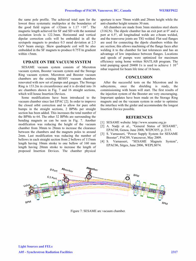
vacuum system, Booster vacuum system and the Storage Ring vacuum system. Microtron and Booster vacuum chambers are the existing BESSY vacuum chambers renovated with new set of pumps and gauges. The Storage Ring is 133.2m in circumference and it is divided into 16 arc chambers shown in Fig. 7 and 16 straight sections, which will house Insertion Devices.
Some modifications have been introduced to the vacuum chamber since last EPAC [2]. In order to improve the closed orbit correction and to allow for pure orbit bumps in the straight sections, 2 BPMs per straight section has been added. This increases the total number of the BPMs to 64. The other 32 BPMs are surrounding the bending magnets as can be seen in Fig. 7. Another modification was reducing the height of the vacuum chamber from 30mm to 28mm to increase the clearance between the chambers and the magnets poles to around 2mm. Last modification was reducing the number of bellows in each straight section from 2 bellows of 115mm length having 10mm stroke to one bellow of 160 mm length having 20mm stroke to increase the length of proposed Insertion Devices. The chamber physical
aperture is now 70mm width and 28mm height while the anti-chamber height remains 30 mm.
All chambers are made from 3mm stainless steel sheets (316LN). The dipole chamber has an exit port at 0° and a port at 6.5°, all longitudinal welds are e-beam welded, and the transverse joints are TIG welded. Flat seal flanges are used for connecting the dipole chambers within the arc section; this allows machining of the flange faces after welding it to the chamber for last tolerances and has an advantage of low impedance between flanges. Locations and speeds of pumps were optimized for maximum efficiency using home written MATLAB program. The total pumping speed 20400 l/s is used to achieve 1 10-9 mbar required for beam life time of 16 hours.
CONCLUSION After the successful tests on the Microtron and its
subsystems, once the shielding is ready, the commissioning with beam will start. The first results of the injection system of the Booster are very encouraging. Important updates have been made on the Storage Ring magnets and on the vacuum system in order to optimise the interface with the girder and accommodate the longest Insertion Device possible.
REFERENCES [1] SESAME website: http://www.sesame.org.jo [2] A. Nadji et al., “General Status of SESAME”,
EPAC08, Genoa, June 2008, WEPC055, p. 2115. [3] S. Varnasseri, “Power Supply System for SESAME
Booster”, PAC09, Vancouver, May 2009. [4] S. Varnasseri, “SESAME Magnets System”,
EPAC06, Sitges, June 2006, WEPLS074.
Figure 7: SESAME arc vacuum chamber.
Proceedings of PAC09, Vancouver, BC, Canada WE5RFP022
Light Sources and FELs
A05 - Synchrotron Radiation Facilities 2317