Status and market opportunities of solid oxide fuel cells ...members.igu.org/old/IGU...
17
International Gas Union Research Conference 2011 Status and market opportunities of solid oxide fuel cells based cogeneration systems Main author O. Posdziech 1 Germany [email protected] Co-authors B. E. Mai 2 C. Wunderlich 3 S. Voss 4 1 EBZ GmbH Fuel Cells & Process Technology, 01307 Dresden, Germany 2 staxera GmbH, 01237 Dresden, Germany 3 Fraunhofer Institute for Ceramic Technologies and Systems, 01237 Dresden, Germany 4 TU Bergakademie Freiberg, Institute of Thermal Engineering, 09596 Freiberg, Germany
Transcript of Status and market opportunities of solid oxide fuel cells ...members.igu.org/old/IGU...
International Gas Union Research Conference 2011
Status and market opportunities of solid oxide fuel cells based cogeneration systems
Main author
O. Posdziech1
Germany
Co-authors
B. E. Mai2
C. Wunderlich3
S. Voss4
1EBZ GmbH Fuel Cells & Process Technology, 01307 Dresden, Germany
2staxera GmbH, 01237 Dresden, Germany 3Fraunhofer Institute for Ceramic Technologies and Systems, 01237 Dresden, Germany
4TU Bergakademie Freiberg, Institute of Thermal Engineering, 09596 Freiberg, Germany
ABSTRACT
The most sustainable technology for conversion of natural gas into electricity and heat in the low to medium power levels, is a Solid Oxide Fuel Cell (SOFC) based Combined Heat and Power (CHP) unit. Electrical efficiencies of up to 60 % and total efficiencies of more than 90 % down to electrical powers of only 1 kW, makes these systems attractive for applications in varying power classes. The range between 10 and 50 kWel is especially promising for competition with conventional CHP units and the electrical grid. Different system layouts options exist to meet the technical requirements of specific applications as well as the cost targets for a early market entry. Main distinguishing features are the method of processing natural gas into a hydrogen-rich reformate (i.e. partial oxidation vs. steam reforming) and the cell stack technology used. As a result, electrical efficiencies, system complexity, and costs vary.
Applied to cogeneration, the overall efficiency has the main impact on the profitability of the CHP unit, provided there is existence of a sufficient heat demand. Electrical efficiencies are dominated by power to heat ratios or the utilization factor, this means the number of operation hours needs to be increased. The calculation of CHP cost saving potentials is impeded strongly by application dependent parameters like profiles of heat and electricity demand as well as local gas and electricity prices. For Germany, payback periods can be calculated since typical load profiles of single and multi-family homes are available. Here, the choice of SOFC system layout depends on the economic viability of electricity feed-in to the grid. If funding is available, high electrical efficiencies are clearly favored. This is also valid for applications where only domestic hot water heating is required. Small base load power generators are profitable provided that the system cost targets can be met.
Larger SOFC system in a power range of >100 kWel face a strong competition by conventional CHP units due to their rather high efficiency and low installation prices of 500 €/kW. But if service and maintenance costs are taken into account (here for SOFC only rough assumptions are possible), the cost considerations seem to be in favor for the SOFC technology.
An increase of security of electricity supply and considerable lowering of CO2 emissions, make the SOFC technology attractive both from an economical and ecological point of view. The reduction of CO2 emissions, which is in the focus of world-wide efforts, can be supported by SOFC-based cogeneration if CO2 is converted in an economical factor.
SOFC stacks, the ‘engine’ of a fuel cell system, are currently at a stage close to commercialization, but extended development efforts are still required. Especially, the improvement of long-term stability of stacks requires a strategic investment since results can only be obtained after several years of operation and testing.
An upcoming application based on the solid oxide stacks is the reverse operation of the SOFC, the electrolyzer mode (SOEC), which is expected to achieve conversion efficiencies up 90 %. Here, not only hydrogen can be generated but also synthesis of carbon based fuels like renewable methane is feasible.

TABLE OF CONTENTS
ABSTRACT ........................................................................................................................ 2TABLE OF CONTENTS ..................................................................................................... 31. Introduction ................................................................................................................ 42. Solid Oxide Fuel Cell Technology ............................................................................. 53. Combined Heat and Power system layouts based on SOFC ................................... 6
3.1. Overview ............................................................................................................... 6
3.2. Catalytic partial oxdiation (CPOX) based systems ............................................... 7
3.3. Steam reforming (SR) based systems ................................................................. 8
3.4. Anode off-gas recirculation (AOGR) based systems ........................................... 8
3.5. Serial connection system (SC) ............................................................................. 8
4. CHP SOFC system prospects ................................................................................... 94.1. Residential micro-CHP applications in Germany ............................................... 11
4.2. Mini-CHP ............................................................................................................ 12
5. Summary and Outlook ............................................................................................ 14Acknowledgements .......................................................................................................... 16References ....................................................................................................................... 16Nomenclature ................................................................................................................... 17List of Tables .................................................................................................................... 17List of Figures ................................................................................................................... 17

1. Introduction
Within the last few years a stagnation or slight reduction in sales has been observed for the European gas markets. The decreasing “end-user” market share of gas boiler installations accounts for this effect while the respective share of heat pumps and solar heating systems is increasing [1]. This effect can be considered as positive for energy efficiency and CO2 reduction in the European economies while it is negative for the business of gas utilities. This drop in sales volumes could however be compensated if attractive opportunities for electricity generation from natural gas are explored. An economically and environmentally favourable scenario is the widespread use of combined heat and power units (CHP), where Solid Oxide Fuel Cells (SOFC) with electrical efficiencies of up to 60 % [2] and total efficiencies of more than 90 % are the most promising solution. Since these high efficiencies are largely independent from the system size, SOFC technology is ideally suitable for cogeneration in low to medium power levels. High electrical efficiencies combined with high-grade heat output make SOFC systems also attractive for trigeneration applications. If gas utilities want to shape the future electricity generation landscape they should seriously consider this option and take an active role in promoting the technology as Japanese gas utilities do already today.
The paper describes the status of SOFC technology, system design options and the related economical and environmental footprints. The results are based on long standing design and operation experiences of a strong German R&D consortium: EBZ, staxera, TU-BAF, and Fraunhofer IKTS that are part of the Fuel Cell Initiative Saxony. EBZ is a system integrator that works in the SOFC development for nine years. Commercial contracts as well as national and European SOFC projects provide EBZ unique experiences in the world-wide SOFC sector. From that, EBZ has a wide knowledge in integrating and operating of different SOFC stacks and system technologies. Staxera is the most advanced European manufacturer of SOFC stacks [3]. staxera uses a planar stack technology providing the highest potential for cost reduction in mass production. Staxera has established a prototype manufacturing and supplies its stacks to industrial manufacturers and system integrators. The Institute of Thermal Engineering of the Technical University Bergakademie Freiberg (TU-BAF) is in the field of combustion physics and investigate combustion processes and develops customized components for SOFC systems like chemical reactors, heat exchangers and afterburners. Fraunhofer Research Institute for Ceramic Technologies and Systems (IKTS) has been conducting research for SOFC materials, components and systems for more than 15 years. Over the years it emerged as central hub of Solid Oxide Fuel Cell technologies in the Dresden region and was instrumental to the founding of so far three industrial SOFC companies. The SOFC cluster in Dresden/Freiberg includes today four companies (EBZ, staxera, sunfire, eZelleron), and more than 100 specialist researchers and engineers. Staxera and EBZ cooperate in the system development in a 1 to 50 kWel range. A 3 kWel demonstration system is in operation to show the maturity of SOFC technology to global customers [4]. An electrical efficiency of 37 % was obtained in the first system iteration loop. EBZ and TU-BAF were key players of the European FlameSOFC project [5], where a SOFC system based on a Thermal Partial Oxidation (TPOX) gas processing step was developed. The system development is continued in FC-DISTRICT, where a Catalytic Partial Oxidation (CPOX) is used. Here, SOFC-based µCHP units as network for district heating are investigated.
The paper gives a short summary of SOFC technology and the state-of-the-art of the stack design. Stack layout options and its advantages and disadvantages in various markets are discussed. Different system layouts will be discussed in terms of its applicability and economical benefits. The comparison of system layouts will cover characteristics like electrical and thermal efficiencies, storage of heat and electricity, peak burner capacity, as well as modulation and load-following capabilities. The gas processing step in the SOFC systems largely defines its complexity and with it the manufacturing cost. It will be shown in form of case studies how the different system designs have its justification under typical application constraints, climatic conditions, economical boundary conditions and housing types. The profitability of a CHP application depends strongly on the installation site: load profiles of power and heat demand, prices for gases and electricity, and, if applicable, prices for electricity that is fed into the grid. A market factor could be the safety of power supply in countries with unstable electrical grids like in emerging economies. Finally, an outlook will be given to an upcoming technology field where SOFC technology is used in an electrolyzer mode. In connection with co-electrolyzation of CO2, electricity being used to convert hydrocarbon fuels like methane or liquid fuels that can be used and stored in today’s available natural gas and fuel infrastructures.

2. Solid Oxide Fuel Cell Technology
A fuel cell can be described as a type of galvanic cell where an external supply of chemical reactants are required for generation of electricity and heat by elctrochemical processes. In Figure 1 a simplified process scheme is presented. A fuel cell consist of two chambers divided by the solid and gas tight oxygen-ion conducting electrolyte. In the air chamber, oxygen is reduced at the cathode to oxygen ions (O2-) which are incorporated into the solid electrolyte. In the fuel chamber, hydrogen and carbon monoxide are oxidized in the presence of the oxygen-ions. The different electrochemical potentials in each chamber lead to a potential difference across the cell which corresponds to the Gibb’s Free Enthalpy of the chemical reactions of hydrogen and carbon monoxide. As a single electrochemical cell delivers limited energy, cells have to be arranged electrically in series and from reactant supply in parallel order. This basic unit consists of a limited number of cells which is called a fuel cell stack and can be located in tubular or planar design.
Figure 1: Solid Oxide Fuel Cell (SOFC).
Among the various fuel cell types the SOFC is characterized by an gas tight, but oxygen-ion conducting solid electrolyte as mentioned and high operation temperatures between 650 and 900 °C. At these temperatures the reaction rates are high and allows the use of non-noble electro-catalysts as electrodes. Due to the high operating temperatures SOFC stacks are relatively insensitive to impurities in fuel gases. CO is considered as a fuel and does not poison the anode as it is in the case in PEM fuel cells. The cooling of the fuel cell is performed by excess air or internal chemical reaction of CH4 to CO2 and water (water gas shift reation) on the anode side of the fuel cell. In Figure 2 a prinicipal view of a SOFC system is presented. A SOFC fuel cell system consists of the fuel cell stack as core component, a fuel processing unit and Balance of Plant (BoP) components, like heat exchangers and afterburner. To control and operate the system in addition to the hot components mentioned above the cold balance of plant components (valves, blowers, pumps, sensors, electrical components) are required. The challenge of SOFC system design starts with optimum system configuration and layout in detail to realize efficient thermal management and compact design, to optimize the design for various operation modes (start-stop, part load, full load) and ends with material and component selection for long life, high robustness and reliability.
Figure 2: Principal SOFC system schematic.
In Table 1 different types of SOFC stacks are presented. The SOFC technology have demonstrated operations times well beyond 20’000 hours with degradation rates less than 0.5 % per 1000 h operation in a system context [2]. Other important technical parameters than lifetime and

degradation important for the SOFC stacks are stack efficiency, pressure loss, fuel gas utilization, heat up time, and cycling capability.
Planar ESC cells stack
Planar ASC cell stack
Planar MSC type stack
Tubular SOFC stack
Hybrid planar/tubular SOFC stack
Developers
Hexis, Bloom Energy, Staxera
Versa Power, CFCL, Topsoe Fuel Cells, Delphi, SOFCPower, NGK Spark Plug
Ceres Power Acumentrics/ Ariston, Mitsubishi Heavy Industries, Toto
Kyocera, Rolls-Royce
Operation temperature
800-900 °C 700-800 °C 600-700 °C 800-900 °C 750-900 °C
Durability high medium - high medium
Combination with reforming technologies
CPOX + SR SR SR SR, CPOX SR
Cost perspectives
low medium low high medium
Table 1: Major SOFC stack design options [7].
3. Combined Heat and Power system layouts based on SOFC
3.1. Overview Power generation based on natural gas is considered as one of the alternatives to current
electricity sources that are either responsible for high CO2 emissions like coal also in regards to public perception considered as unsafe like nuclear power or in the reliability of high fluctuations like wind and solar power. In order reach considerable savings of CO2 emissions, Combined Heat and Power units needs to be applied where a continuous demand of heat exists like in residential or commercial applications or the public sector. SOFC-based CHP units are one of the most interesting options due to its high electrical efficiency potentials of up to 60 % independent from the system size.
Catalytic partial oxidation
Steam reforming Anode off-gas recirculation with steam reforming
Serial stack connection [6]
Electrical efficiency 30 – 35 % SOFC: 45 - 50 (60) % PEMFC: 30 – 35 %
50 – 60 % 45 – 50 %
Overall efficiency 85 – 95 % 85 - 95 % 85 – 95 % 85 – 95 %
Power to heat ratio 0.5 – 0.7 1 – 2.2 0.5 – 0.7
1.3 – 2.3 1 – 1.3
Prototypes (SOFC)
Hexis, Vaillant, Ariston
Tokyo Gas, JX Nippon Oil, Kyocera/Osaka Gas, NGK Spark Plug, CFCL, Bloom Energy
Wärtsilä -
Sensitive to gas and water quality
no yes partly partly
System costs and complexity
low high high medium
Table 2: Comparison of SOFC system performance for different gas processing options.
SOFC system layouts can be distinguished by how a stack compatible fuel (H2, CO, CH4 plus H2O and CO2 to avoid soot formation) is processed by a reforming reaction; and in case of a steam

reforming based system how water/steam and heat are provided. A coupling of different gas processing versions is done by connection of two or more stacks in series [6]. Details of different system layouts as well as advantages and disadvantages are discussed in the following chapters. Table 2 shows a comparison of system layouts in terms of electrical efficiency, overall efficiency, power to heat ratio (generated electrical power divided by usable heat), sensitivity to gas and water quality and system costs and complexity. The power to heat ratio is especially important for the matching of the application load profiles with the performance of the CHP unit. Details will be discussed in Section 4. It can be seen that systems that are based on catalytic partial oxidation (CPOX) have the lowest electrical efficiency but are favored in terms of low costs and complexity. The systems become more complex and costly towards steam reforming and anode off-gas recirculation.
In Figure 3 the investigated system layouts are presented and a description of the different layouts is given in the following.
Figure 3: Comparison of SOFC system layouts: a) CPOX based, b) Steam reforming based, c) Anode off-gas recirculation based, d) Serial stack connection with CPOX and SR stage.
3.2. Catalytic partial oxdiation (CPOX) based systems A CPOX system is based on a partially under-stoichiometric reaction supported by a catalyst
material (normally precious metal) where air and natural gas are converted to mainly hydrogen and carbon monoxide. The system layout is very simple, as shown in Figure 3 a), with a minimal number of components. Thereby, the system has the prospective to be very cost effective. A further advantage is that no water supply and processing is required. Since the fuel is partly oxidized in the CPOX reactor, the reforming efficiency is maximal 80 % in dependency on the air ratio. A minimal air ratio in the range of 0.27 to 0.31 has to be applied. Here, electrical efficiencies of 30 to 35 % can be achieved. Since the lowest air ratio is connected with the highest electrical efficiency but also with an increased probability of soot formation, the control of a CPOX based system is challenging especially if higher hydrocarbons are present from different natural gas qualities. Disadvantageous is also the rather high air demand for stack cooling since no internal reforming can be used. The power to heat ratio of CPOX based systems is in the range of 0.5 to 0.7 only; these systems will most probably be applied for µCHP applications in the range of 0.5 to 5 kW where a high yearly heat demand exists like in residential applications in some parts of Europe and North America. System installation and operational costs (no water deionization) are expected to be lowest compared to the alternatives.
a) b)
c) d)
3.3. Steam reforming (SR) based systems Steam reforming based systems are the preferred option if high electrical efficiencies are the
target. Here, CFCL, an Australian based SOFC developer, has demonstrated electrical efficiencies of up to 60 % in the 1.5 kWel range. This is on a par with the latest generation of natural gas based combined cycle power plants in the MW scale. An exemplary system layout is shown in Figure 3 b). Here, deionized water is needed for the reforming reaction which increases operational costs. A larger number of components with heat interaction are required compared to the CPOX based system layout. To perform stable long-term water and steam generation is sophisticated. The steam reformer is normally designed as pre-reformer to crack higher hydrocarbons and supply starting amount of hydrogen for the stack. The complete reforming is performed directly at the anode. This process is called internal reforming. It reduces the heat demand of the steam reforming reactor and, due to the endothermic process, the cooling demand for the stack. The parasitic losses of the air blower are considerably reduced due to the reduced need for cooling air on the cathode side. A steam reformer works stable and soot-free in a rather high operation window in terms of temperature as well as the ratio of natural gas and water. It converts heat into fuel enthalpy so that the overall fuel-based efficiency is 120 %. Normal electrical efficiencies of SR based systems range between 45 and 50 % in extreme cases up to 60 %. Power to heat ratios of 1 up to 2.2 predestine SR based systems for all sizes of CHP units where the power demand is high compared to the heat demand. Residential applications in moderate climates are one example or systems that should get a higher number of operation hours.
3.4. Anode off-gas recirculation (AOGR) based systems A steam reforming reactor requires an external deionized water supply or a condensation of
water from the exhaust gas together with water purification and re-evaporation. Since the electrochemical process forms H2O out of H2, it is self-evident to use the steam as oxidant for the natural gas. The recirculation of anode off-gas (mixture of H2, CO, CO2, H2O), does not only provide steam but also increases the overall fuel utilization and with it the electrical efficiency of the system that is normally in the range of 50 to 60 %. One exemplary process scheme is shown in Figure 3 c). Here, a hot gas recirculation blower (T>600 °C) is used. Other process layouts can be based on a cold recirculation blower plus a heat exchanger for the anode off-gas or an ejector and a natural gas compressor. The availability, reliability and costs of the main components, especially the recirculation blower, is critical. Also the measurement and control of the recirculation rate, that is required for a soot-free reformer and stack operation, is a challenge. It is believed that anode off-gas recirculation is mainly an option for larger systems (>50 kWel) due to specific costs of critical components.
3.5. Serial connection system (SC) The serial connection of at least two SOFC stacks is another alternative to process natural
gas. The idea is close to AOGR. In principle a first stage is operated under CPOX and the off-gases are recycled in following stages under SR. Most important is the steam production during load operation inside the stack of the CPOX stage. In combination with a methane (natural gas) feed in front of the SR stages the efficiency can be increased. At the same time no additional water processing is necessary and in contrast to AOGR no critical high temperature components are required. The characteristic of a two stage SC system with combined CPOX and SR is shown in Figure 3 d). A detailed presentation of theoretical and experimental results that have been obtained in cooperation between staxera and EBZ can be found in [6]. Figure 4 shows the efficiency and power potentials if further steam reforming stages are connected. The electrical efficiency (here only the stack efficiency is given) comes close to 60 % as can be obtained with a pure SR based system. The total power and number of cells is increasing from stage to stage. However, also the pressure losses at the air and gas side are increasing. This system layout shows a high electrical efficiency potential without costly water processing or AOGR. However, it is more complex than a simple CPOX system due to an additional gas control and the inverter complexity. For these reasons this layout is above all an option for small systems in the range of 5 to 20 kWel.

Figure 4: Electrical efficiency, number of cells and overall power for several stack stages.
4. CHP SOFC system prospects
A summary of the different electrical and thermal efficiency potentials compared with PEM fuel cells (steam reforming based) and conventional CHP units [8] is shown in Figure 5. The SOFC efficiencies are not grouped in power classes since in theory efficiency is independent from the system size. PEMFC systems have electrical efficiencies of 35 to maximum 40 % where they are comparable with CPOX based layouts. Conventional CHP units show rather modest electrical efficiencies of below 30 % in a range of 5 to 10 kWel but achieve 40 % in the 1 MW size. It can be seen that SOFC technology shows its strengths in a power range below 50 kWel, where its electrical efficiency is more than 15 % superior to the conventional technology.
Figure 5: Efficiency of SOFC based systems compared to CHP alternatives [8].
An economical favorable cogeneration solution is above all a question of matching system properties and characteristics of the application site. This makes it challenging to provide general rules about the profitability of CHP applications. On the system side, there are above all cost considerations that count: costs of the first installation, operational costs (in case of SOFC systems water deionization
0
1
2
3
4
5
6
7
8
9
10
11
12
5
10
15
20
25
30
35
40
45
50
55
60
65
0 1 2 3 4 5 6
Tota
l ele
ctri
cal p
ower
[kW
]To
tal N
o. o
f cel
ls [1
*10]
Tota
l effi
cien
cy [%
]
No. of stages
EfficiencyPowerNo. of cells
CPOXstage
SR stages
0 10 20 30 40 50 60 70 80 90 100
CHP unit 5 kWel
CHP unit 50 kWelCHP unit 237 kWelCHP unit 402 kWel
CHP unit 1.063 kWel
SOFC CPOX
SOFC SRSOFC SC
SOFC AOGR
PEMFC SR
Overall efficiency [%]
Electrical efficiency [%] Thermal efficiency [%]

and above all desulphurization) as well as general costs of service and maintenance including a complete overhaul of the system as it is practice in conventional CHP units after ten years. SOFC applications have not reach marketability in the past few years due to systems only being applied in lower quantities in field tests. Nevertheless business cases become very attractive as soon as higher number of units will be installed. Further factors that have an impact on profitability are the electrical and overall efficiencies together with the power to heat ratio, part load capability, speed of load changes, start/stop characteristics and storage capacity for heat, and maybe in the future also for electricity. SOFC systems, especially if steam reforming is applied, are normally limited in the speed of load following. The part load efficiency is excellent, especially the electrical efficiency is increased if the system in operated under part load conditions. A challenge still to be adressed is the limited start/stop characteristic of SOFC technology: frequent start/stops increase stack degradation and heat up times can amount to several hours. Therefore, the system should be applied mostly for base-load operation. Here, also the heat storage capacity is playing a major role in reaching high utilization factors. Technical solutions among others could be the hot stand-by operation of SOFC systems.
Even more diverse than system properties are the application characteristics. Potential CHP applications range from residential over commercial (hotels, hospitals, office buildings, etc.) to small-scale industries. Here daily and seasonal load profiles for heat and electricity demands needs to be explored in detail in order to adjust CHP system size with the demand and design storage systems etc. If no process heat is required like in breweries, hospitals or other industries, the climate plays a major role in system options. A rather high yearly heat demand in Central, Northern and Eastern Europe favor systems with a low power to heat ratio as can be seen in Table 3, whereas mild climates in Southern Europe or Asia have partly only a domestic hot water (DHW) demand, but might have considerably higher electricity demands due to air conditioning than the typical German home. The daily and seasonal load profiles determine the utilization ratio, that means how many full load yearly operation hours can be collected and with it the payback period. In countries, where the heat demand is restricted to domestic hot water demand, the high electrical efficiency of SOFC CHP units is a market driver.
Yearly specific heat demand 150 m²
Electricity demand (4 persons assumed)
Domestic hot water demand
Average power-to-heat ratio
No heat demand - 7,000 kWh/a 2,000 kWh/h 3.5
Low-energy house 6,000 kWh/a 7,000 kWh/a 2,000 kWh/h 0.9
Building after 2002 11,250 kWh/a 7,000 kWh/a 2,000 kWh/h 0.5
Building 1977-2002 24,000 kWh/a 7,000 kWh/a 2,000 kWh/h 0.3
Building before 1977 45,000 kWh/a 7,000 kWh/a 2,000 kWh/h 0.15
Table 3: Comparison of different building types in terms of heat and electricity demands for typical 150 m² single family homes in Germany (from VDI 4655).
A second important factor that determines the CHP economics is the gas and electricity price or more exact the price difference between gas price and (substituted) electricity price. Taking the European Community as an example, large differences exist between the countries and between households and industrial sector. A summary of natural gas and electricity prices is shown in Table 4. Natural gas prices are similar for households with the exception of the United Kingdom that has a 30 % lower price. However, the electricity price is nearly 50 % lower in France compared to Germany. micro-CHP might be an option in Germany, but has complex economical prospects in France. The situation is partly different in the industrial sector: Here, France is again the country with the lowest electricity price, but also Germany is reasonably low priced. Italy would be the favored country for ‘larger-scale’ CHP units in industry with a bigger difference between natural gas and electricity price.
Besides the hard economical data there are more criteria that impact the market prospects: subsidies, acceptance of power feed-in in the grid (i.e. in Japan no feed-in is allowed today, wheras CHP-Power receives an additional grant when fed into the grid in Germany), CO2 taxation and

awareness as well as local grid stability could contribute to a decision pro CHP, but are difficult to explore in a business plan. In the following, some details about micro-CHP and mini-CHP market prospects will be given.
Natural gas price households
Electricity price households
Natural gas price industry
Electicity price industry
France 40.2 €/MWh 125.6 €/MWh 25.5 €/MWh 74.6 €/MWh
Germany 43.6 €/MWh 237.5 €/MWh 28.1 €/MWh 112.0 €/MWh
Italy 47.6 €/MWh 196.7 €/MWh 22.9 €/MWh 138.9 €/MWh
Spain 41.2 €/MWh 172.8 €/MWh 21.4 €/MWh 116.7 €/MWh
United Kingdom 31.3 €/MWh 138.6 €/MWh 16.5 €/MWh 98.9 €/MWh
Table 4: Natural gas and electricity prices in main European markets [9].
4.1. Residential micro-CHP applications in Germany Mirco-CHP units can be applied in single or multi-family homes in the range of 1 to 5 kWel. In
Japan, 700 W units are normally used due to low heat demands and prohibition to feed electricity to the grid. EBZ has performed an extensive comparison of different system strategies CPOX based SOFC systems versus steam reforming based systems and heat driven (the system load follows the heat demand of the application) versus electricity driven (the load follows the electricity demand) driven operation. CPOX systems (example Hexis Galileo 1000 N) have electrical efficiencies of maximum 35 %, whereas SR systems can have up to 60 % efficiency (CFCL BlueGen). The overall efficiency is typically between 85 and 90 %. Individual user profiles according to the regulation VDI 4655 are applied, where load curves for heat, domestic hot water demand and electricity are given in 1 and 15 min intervals. One example is shown for the transition period where the heat and electricity demand is equal. In the winter period, the heat demand is much higher than the electricity demand, whereas in summer only domestic hot water is required.
Figure 6: Typical load profiles for electricity and heat in the transition period (autumn and spring) for a German single-family home build after 2002.
0
0,5
1
1,5
2
2,5
1:00
2:00
3:00
4:00
5:00
6:00
7:00
8:00
9:00
10:0
0
11:0
0
12:0
0
13:0
0
14:0
0
15:0
0
16:0
0
17:0
0
18:0
0
19:0
0
20:0
0
21:0
0
22:0
0
23:0
0
0:00
Time
Elec
trici
ty a
nd h
eat d
eman
d [k
W]
PelPth

If VDI 4655 is applied, the number of residents, house type and climate zone have to be taken into account. Of course, this typical load profiles are only a very imprecise representation of individual house characteristics and personal habits. Results will be presented for a single-family house with four persons and 500 liter heat storage. The maximal power output of the CPOX system is 1 kWel and of the SR system 1.5 kWel. The overall efficiency is 90 % in the first case and 85 % in the second. The sample systems are all modulating. If the storage is completely filled, the systems have to be switched off.
The feed-in of electricity using micro-CHP is currently funded in Germany with 5 ct/kWh additionally to the normal 5 ct/kWh tarif. This funding supports especially the BlueGen unit because of its higher electrical power output as is shown in Figure 7. Here, cost savings are shown by substitution of power supply from the grid, substitution of gas usage for heating and feed-in of electricity. If there is no funding, the Hexis Galileo 1000 N is the more profitable solution due to its higher overall efficiency. This shows that the feed-in of a higher amount of electricity isn’t an economically viable solution without additional CHP subsidies at least in the German market.
Figure 7: Cost saving potentials of CPOX (Galileo 1000 N) and SR (BlueGen) based systems operated in heat driven mode.
Assuming a payback period of five years, the maximal costs of the systems have to be in the range of totally 1500 € if no funding is available and with funding 2000 € for the Galileo 1000 N respectively up to 3000 € for the BlueGen system. It is assumed that the costs are about 50 % of the end-user price. The differences in the overall cost savings between heat and electricity driven operations are negligible. Further calculations were performed with only domestic hot water demand. This is the case in Germany during summer period, where it’s normally not useful to operate the CPOX system, and a typical case for apartments and single-family houses in Mediterranean climates. Here, a higher electrical efficiency is very favorable. The optimal peak power is expected to be in the range of 500 W. This corresponds to the yearly average electricity demand of a four person family. The cost savings are surprisingly high in this configuration (about 2/3 of a 1.5 kW system with heating application).
4.2. Mini-CHP Mini cogeneration is usually more than 5 kWel and less than 500 kWel in a building or medium
sized business. In this power classes, the maximization of the utilization factor of the CHP unit is important since it will greatly affect the efficiency and cost effectiveness (payback time). The utilization factor is essentially the calculated hours of operation of the CHP plant expressed as a percentage of the total number of hours in a year. To be economical, a good base load for electrical demand and heat demand must exist. Such base loads arise where building occupation or process activities are extended or continuous in operation. This typically includes for hospitals, manufacturing processes, swimming pools, airports, hotels, apartment blocks, etc. Some of these applications might have the
0
2.000
4.000
6.000
8.000
10.000
12.000
14.000
1 2 3 4 5 6 7 8 9 10Year
Cos
t sav
ings
[€]
BlueGenFunding ON
Summer OFF
BlueGenFunding OFF
Summer OFF
Galileo 1000 NFunding ON
Summer OFF
Galileo 1000 NFunding OFF
Summer OFF
potential for trigeneration to extend heat usage. The matching of system characteristics with the local heat and electricity demand is difficult, particularly since the applications are so different. Standard load profiles do not exist. Therefore, the profitability calculations of MiniCHP plants cannot be generalized. In order to provide some cost target assumption, SOFC based CHP systems will be compared in the following to conventional CHP in terms of costs (or prices) and efficiencies. Electrical efficiencies of both technologies were already given in Figure 5. Data for the conventional CHP plants are taken from [8]. Smaller CHP units in the range of <50 kWel have normally electrical efficiencies of below 30 % compared to more than 50 % for SOFC systems. If the system size becomes larger, also the efficiencies of conventional CHP increase up to 40 %. This is still 10 to 15 % below the SOFC potential.
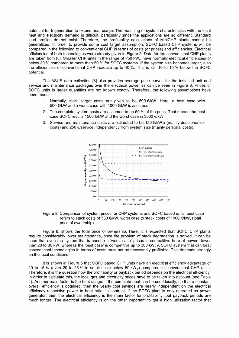
The ASUE data collection [8] also provides average price curves for the installed unit and service and maintenance packages over the electrical power as can be seen in Figure 8. Prices of SOFC units in larger quantities are not known exactly. Therefore, the following assumptions have been made:
1. Normally, stack target costs are given to be 500 €/kW. Here, a best case with 500 €/kW and a worst case with 1000 €/kW is assumed.
2. The complete system costs are assumed to be 50 % of the price. That means the best case SOFC results 1500 €/kW and the worst case in 3000 €/kW.
3. Service and maintenance costs are estimated to be 120 €/kW.a (mainly desulphurizer costs) and 250 €/service independently from system size (mainly personal costs).
Figure 8: Comparison of system prices for CHP systems and SOFC based units: best case refers to stack costs of 500 €/kW, worst case to stack costs of 1000 €/kW, (total price of ownership).
Figure 8, shows the total price of ownership. Here, it is expected that SOFC CHP plants require considerably lower maintenance, once the problem of stack degradation is solved. It can be seen that even the system that is based on ‘worst case’ prices is competitive here at powers lower than 20 to 30 kW, whereas the ‘best case’ is competitive up to 300 kW. A SOFC system that can beat conventional technologies in terms of costs must not be necessarily profitable. This depends strongly on the local conditions.
It is shown in Figure 5 that SOFC based CHP units have an electrical efficiency advantage of 10 to 15 % (even 20 to 25 % in small scale below 50 kWel) compared to conventional CHP units. Therefore, it is the question how the profitability or payback period depends on the electrical efficiency. In order to calculate this, the local gas and electricity prices have to be taken into account (see Table 4). Another main factor is the heat usage: If the complete heat can be used locally, so that a constant overall efficiency is obtained, then the yearly cost savings are nearly independent on the electrical efficiency respective power to heat ratio. In contrast, if the SOFC plant is only operated as power generator, then the electrical efficiency is the main factor for profitability, but payback periods are much longer. The electrical efficiency is on the other important to get a high utilization factor that
0 €
500 €
1.000 €
1.500 €
2.000 €
2.500 €
3.000 €
3.500 €
4.000 €
4.500 €
5.000 €
0 50 100 150 200 250 300 350 400 450 500Electrical power [W]
10 y
ear
over
all p
rice
[€/k
Wel
]
CHP averageSOFC system best caseSOFC system worst case
means higher number of operation hours at high loads which decreases the payback period. A detailed analysis is beyond the scope of the current paper and could be requested from the main author.
Distributed generation based on SOFC technology with its high electrical efficiencies has the highest potential for CO2 and primary energy use reduction. However, the local situation of the primary fuel shares for electricity generation in the national electricity grid has to be considered: A nuclear or hydropower based national power supply is different from a coal based power generation. Also the competition with electrical heat pumps has to be considered. On the other hand, a combination of heat pump and electrically efficient SOFC system seems to be the optimum solution in terms of CO2 reductions. Assuming an overall efficiency of 90 %, than the CO2 saving potential in Germany is between 20 % and 50 % dependent on the electrical efficiency. Furthermore, the systems do normally have minimal CO and NOx emissions.
5. Summary and Outlook
Solid Oxide Fuel Cell technology is a viable option for a clean, reliable and profitable conversion of natural gas in electricity and heat. Electrical efficiencies up to 60 %, which can be achieved in all power classes, combined with an effective heat usage shows high potentials in the micro- and mini-CHP sector. It was shown that above all applications in a range of up to 50 kWel are attractive due to low electrical efficiencies of competing technologies and comparably high costs. Markets that have low natural gas compared to electricity prices are attractive for CHP applications. Germany and Italy are in Europe main markets due its high household electricity prices, whereas France is a no-go market. In the industrial sector, Italy is the most attractive market from an electricity price point of view.
Advantages and disadvantages of different system layouts were discussed in the paper. The simplest system uses CPOX as fuel processing unit. The main drawback is the limited efficiency of fuel conversion and thus of the SOFC system. Gas processing via steam reforming yields to high system efficiency, but requires costly water processing. For larger units (>10 kWel), anode off-gas recirculation is a viable option: Steam that is generated in the electrochemical reaction of fuel cells is recirculated to the system inlet and mixed with the fuel. Availability and costs of a hot-gas recirculation blower are critical, so this is only an option for larger systems. EBZ and staxera have developed and tested an innovative layout with a serial connection of CPOX and steam reforming driven SOFC stacks as a compromise to reach high electrical efficiencies without the necessity of complex water processing steps. The different system layouts might all find their special market, where the resulting system fits best to its power and heat demand. Important factors for the identification of the most suitable process scheme were given. CPOX based systems will find its application in the micro-CHP sector where a higher heat demand exists, whereas AOGR-systems are expected to become competitive only in large scale. Serial connection of stacks is expected to be useful in smaller scale between 5 and 20 kW.
Fuel cell based micro- and mini-CHP systems typically have the highest power to heat ratios, expected to be in the range of 0.7 to 2.4. They can therefore potentially be run in an ‘electrically led’ operating mode, sized to generate electricity constantly with the associated heat, providing a small part of the overall on-site heating or hot water requirements, with a separate boiler providing their main heat needs. This type of operation is particularly suited to fuel cell systems which are expected to have long start-up times and will therefore perform best over very long operating periods. However, in some applications electricity-led schemes may find it difficult to use the heat produced, especially during the summer. In practice, any micro-CHP system which operates constantly and independently of the level of demand for heat or hot water, is likely to require a thermal store to decouple the operation of the device from the on-site demand and avoid any useful heat being wasted.
The profitability of SOFC applications was shown for the micro-CHP sector and German market conditions. Here, load profiles for heat and electricity demands in typical German single family homes were used to calculate the cost saving potentials. It should be noted that this results fit only to the situation in Germany. For mini-CHP, the calculation of profitability is challenging. Here, not only conditions like gas and electricity price, storage size etc. are important, but above all the yearly and

daily electricity and heat demands of the application. These demands vary considerably within the different residential, commercial or industrial installations. In order to assess some economical targets, SOFC technology was compared to conventional CHP units. It was shown, that SOFC is competitive in smaller scale especially if total cost of ownership is considered. This is valid of both best and worst case scenarios for future production costs of SOFC stacks. Also in larger scale, the overall efficiency is dominant, provided that the heat demand of the application is steady. In case of low heat demands and if minimal payback periods should be achieved, a high electrical efficiency is required.
The power to heat ratio of a SOFC based CHP system is the key parameter to consider when assessing the potential carbon savings for different units. The higher the power to heat ratio the higher the proportion of electrical output and therefore the greater the potential carbon savings for a given energy input. CO2 emission reductions between 20 and 60 % can be achieved. However, the basis of this calculation is difficult to define and under stronger discussion.
An effective conversion of natural gas into electricity with electrical efficiencies of up to 60 % is not the only strength of SOFC. A high-temperature electrolyzer results if the stack is operated in the reverse mode. This SOEC application reaches conversion efficiencies of up to 90 %. Together with co-electrolysis of CO2, a sustainable conversion of electrical power into methane or even liquid fuels is possible. This renewable methane is storable in the natural gas grid and available storage infrastructure. With it, the problem of fluctuating availability of renewable power source (photovoltaic and wind) can be completely solved. If electricity prices are concerned, the production of renewable methane is attractive to be performed in France, whereas the power generation should be done with SOFC technology in Germany.

Acknowledgements The authors would like to thank the European Commission for the financial support of this
work within the 6th and 7th framework program, the Free State of Saxony and different German funding agencies for the co-financing of SOFC stack and system developments.
References
[1] A. Ley, J.C. Möller, L. Speer, S. Straßburg: Innovative Technologien zur erergetischen Nutzung von Gas, DVGW final report, 2009.
[2] K. Föger: Commercialisation of CFCL’s Residential Power Station – BlueGen. In: Proceedings of the 9th European Solid Oxide Fuel Cell Forum, p. 2-22, 2010.
[3] C. Wunderlich, J. Lawrence: Status of system integration and robustness of Staxera ISM products. In: Proceedings of the 9th European Solid Oxide Fuel Cell Forum, p. 2-116, 2010.
[4] O. Posdziech, M. Pruggmayer, B.-E. Mai, J. Lawrence: Operational Results of a 3 kW Research and Demonstration System. In: Proceedings of the 9th European Solid Oxide Fuel Cell Forum, p. 2-124, 2010.
[5] O. Posdziech, S. Voss, R. Marin: Results from the evaluation tests of the complete FlameSOFC unit for gaseous fuel. Public Final FlameSOFC Workshop, Lucerne, 2010.
[6] D. Schimanke, O. Posdziech, B.-E. Mai, T. Strohbach, S. Kluge, C. Wunderlich: Demonstration of a Highly Efficient SOFC System with Combined Partial Oxidation and Steam Reforming, In: Proceedings of the 219th ESC Meeting, Montreal SOFC XII, 2011.
[7] Data in Table 2 have been accumulated based on publications from different companies. They need objective validation in many cases and might be modified afterwards. In some cases the name of the stack developer is known and given in the table. In other cases the stack developer is identical to system developer and its name is given
[8] ASUE: BHKW-Grundlagen, 2010.
[9] EUROSTAT: Natural gas prices for first semester 2010, European Union 2010.

Nomenclature
AOGR anode off gas recirculation
ASC anode supported cell PEFC polymer electrolyte fuel cell
CHP combined heat and power R&D research & development
CPOX catalytic partial oxidation SOFC solid oxide fuel cell
ESC electrolyte supported cell SR steam reforming
MSC membrane supported cell SOEC solid oxide electrolyzer cell
List of Tables
Table 1: Comparison of SOFC system performance for different gas processing options
Table 2: Major SOFC stack design options [7]
Table 3: Comparison of different building types in terms of heat and electricity demands for typical 150 m² single family homes in Germany (from VDI 4655).
Table 4: Natural gas and electricity prices in main European markets (Eurostat data [9]).
List of Figures
Figure 1: Solid Oxide Fuel Cell (SOFC).
Figure 2: Principal SOFC system schematic.
Figure 3: Comparison of SOFC system layouts: a) CPOX based, b) Steam reforming based, c) Anode off-gas recirculation based, d) Serial stack connection with CPOX and SR stage.
Figure 4: Electrical efficiency, number of cells and overall power for several stack stages.
Figure 6: Typical load profiles for electricity and heat in the transition period (autumn and spring) for a German single-family home build after 2002.
Figure 7: Cost saving potentials of CPOX (Galileo 1000 N) and SR (BlueGen) based systems operated in heat driven mode.
Figure 8: Comparison of system prices for CHP systems and SOFC based units: best case refers to stack costs of 500 €/kW, worst case to stack costs of 1000 €/kW, a): only installation costs, b): total price of ownership.