Fundamental and Applied Numerical Approaches for CO2 ...members.igu.org/old/IGU...
10
Fundamental and Applied Numerical Approaches for CO 2 Capture in Flue Gases within a Supersonic Nozzle Erwin George 1 , Agathe Jarry 1 , Mailys Pale 1 and Samuel Saysset 1 1. GDF SUEZ, R&T Division – CRIGEN - 361, Avenue du Président Wilson – 93211 Saint Denis la Plaine Cedex – France Abstract This paper deals with the technical expertise on low temperature CO 2 separation processes developed by GDF SUEZ – CRIGEN (Center for Research and Innovation on Gas and New Energies) in the framework of the GDF SUEZ CCS Corporate Program. One of the low temperature CO 2 capture process which is currently under development for post-combustion CO 2 capture is based on flue gas cooling through isentropic expansion in a supersonic nozzle. To achieve a preliminary assessment of this technology, GDF SUEZ - CRIGEN developed a Matlab ® tool (1D and 2D modeling and design of the nozzle). This low temperature separation system can be adapted for several gas separation applications (gas dehydration, acid gas removal, NGL separation …). We will here present physical phenomenon occurring in a low temperature supersonic nozzle and give an overview of both modeling methodology and preliminary results obtained in this study. 1. Introduction GDF SUEZ - CRIGEN performed a benchmark of low temperature CO 2 removal processes for different gas treatment applications, with a focus on post-combustion CO 2 capture.. Among them, Inertial Carbon Extraction System (ICES) – ATK / ACEnT Labs (USA), was identified as a breakthrough and promising process. The principle of this innovative system is thorough cooling through flue gas expansion within a supersonic nozzle: flue gas is only moderately compressed (2-4 bar a ), then expanded supersonically through a converging / diverging nozzle down to low sub-atmospheric pressure levels, in order to reach a temperature at which CO 2 desublimates: in this process, potential energy (P, T) is converted into kinetic energy. Once precipitated solid CO 2 has been removed from the flue gas stream by centrifugal effect of the flow and through a capture duct, lean flue gas is recovers to atmospheric pressure and sent into the stack, without any mechanical compression, through a convergent / divergent diffuser. Figure 1 : Principle of the ICES system (source and property: ATK and ACEnT Labs) i Technology was thus further assessed by GDF SUEZ - CRIGEN through modeling. Methodology been developed for this purpose and main results are described in this paper have been developed for this purpose.
Transcript of Fundamental and Applied Numerical Approaches for CO2 ...members.igu.org/old/IGU...

Fundamental and Applied Numerical Approaches for CO2 Capture in Flue
Gases within a Supersonic Nozzle
Erwin George1, Agathe Jarry
1, Mailys Pale
1 and Samuel Saysset
1
1. GDF SUEZ, R&T Division – CRIGEN - 361, Avenue du Président Wilson – 93211 Saint Denis la Plaine Cedex –
France
Abstract This paper deals with the technical expertise on low temperature CO2 separation processes developed by GDF
SUEZ – CRIGEN (Center for Research and Innovation on Gas and New Energies) in the framework of the GDF
SUEZ CCS Corporate Program. One of the low temperature CO2 capture process which is currently under
development for post-combustion CO2 capture is based on flue gas cooling through isentropic expansion in a
supersonic nozzle. To achieve a preliminary assessment of this technology, GDF SUEZ - CRIGEN developed a
Matlab® tool (1D and 2D modeling and design of the nozzle). This low temperature separation system can be
adapted for several gas separation applications (gas dehydration, acid gas removal, NGL separation …). We will
here present physical phenomenon occurring in a low temperature supersonic nozzle and give an overview of
both modeling methodology and preliminary results obtained in this study.
1. Introduction
GDF SUEZ - CRIGEN performed a benchmark of low temperature CO2 removal processes for different gas
treatment applications, with a focus on post-combustion CO2 capture..
Among them, Inertial Carbon Extraction System (ICES) – ATK / ACEnT Labs (USA), was identified as a
breakthrough and promising process. The principle of this innovative system is thorough cooling through flue
gas expansion within a supersonic nozzle: flue gas is only moderately compressed (2-4 bara), then expanded
supersonically through a converging / diverging nozzle down to low sub-atmospheric pressure levels, in order to
reach a temperature at which CO2 desublimates: in this process, potential energy (P, T) is converted into kinetic
energy. Once precipitated solid CO2 has been removed from the flue gas stream by centrifugal effect of the flow
and through a capture duct, lean flue gas is recovers to atmospheric pressure and sent into the stack, without any
mechanical compression, through a convergent / divergent diffuser.
Figure 1 : Principle of the ICES system (source and property: ATK and ACEnT Labs)i
Technology was thus further assessed by GDF SUEZ - CRIGEN through modeling. Methodology been
developed for this purpose and main results are described in this paper have been developed for this purpose.

In this technology flue gases or streams to be treated are injected (at moderate pressure for post-combustion flue
gases) in a convergent/divergent nozzle. If this flow is sonic at the throat of the properly-contoured nozzle
(through initial low backpressure), an near-isentropic expansion then occurs up to the point of condensation.
Consequences are:
Large reduction in static pressure,
High Large reduction in static temperature,
Increase of the flow velocity in the divergent part (supersonic regime).
Due to these flow changes, the local fluid properties are known to lead to a phase change under certain
circumstances. Indeed, at a certain pressure and temperature level, one or more of the gas-phase components
may transform from vapor phase to liquid or solid phase. In the case of CO2 in the flue gas, the isentropic
expansion may lead to a vapor-to-solid phase change (also called “desublimation”) after the temperature and
partial pressure of CO2 passes through the theoretical sublimation line as shown in Figure 2. Of course this
condition requires what is known as heterogeneous nucleation to avoid the high super-saturation required if there
are no particles (i.e. ash, dust or condensed water). Practical systems generally contain such media so
heterogeneous condensation is expected.
Figure 2. Isentropic expansion of 14mol% CO2 in N2 relative to phase diagram of CO2ii
2. Fundamental Numerical modeling
The GDF SUEZ - CRIGEN modeling team further investigated this technology using a numerical approach. The
first approach was purely “fundamental” and a dedicated code was developed using Matlab® software including:
Main physical phenomena in supersonic confined streams,
1D approach, with a correction of calculated fluid properties, which took into account the shock waves.
2D approach, using Euler equations solved for each cell of a mesh (based on 1D geometry).
a. Isentropic Steady Flows and Mach number relations
An isentropic approximation is very common in compressible-flow theory for nozzle flows without shock waves
and heat transfer. The isentropic approximation greatly simplifies a compressible-flow calculation. So does the
assumption of adiabatic flow, even if non-isentropic.
0.0
2.0
4.0
6.0
8.0
10.0
12.0
0.001
0.01
0.1
1
10
100
50 100 150 200 250 300
Ma
ch N
um
be
r
Pre
ssu
re [
ba
r]
Temperature [K]
Isentropic Expansion of 14mol% CO2 in N2 Relative to Phase Diagram of CO2
Triple Point
Partial Pressure of CO2
during Isentropic Expansion in Supersonic Nozzle(p0=2bar, T0=300K)
Region of incipient condensation
Gas Phase
Liquid Phase
Solid Phase
Post Condensation
Path

Considering high-speed gas flow, in addition to isentropic and adiabatic assumption (TdS=0, Q=0), there is no
shaft work delivered to any part of the fluid. Therefore in a nozzle every streamline in the flow satisfies the
steady-flow energy equation (Bernoulli’s formulation) [1] [2]:
(Eq.1)
where point 1 is upstream of point 2. ho is called the stagnation enthalpy of the flow which is conserved.
The dimensionless form of Eq.1 is obtained dividing it by CpT:
(Eq.2)
From the perfect-gas law, by using
for the speed of sound of a perfect gas, and introducing the Mach
number Ma as a parameter, by using
for the speed of sound of a perfect gas, Eq.2 becomes [2]:
(Eq.3)
This relation is plotted in Figure versus the Mach number for =1.4. At Ma = 5, the temperature has dropped to
1/6 T0. All other quantities are deduced from the theory of perfect gases.
Figure 3: Adiabatic and isentropic quantities versus Mach number - =1.4 (source [1]).
Coupling both perfect gases theory and Laplace relations for gases1, global flow quantities are characterized as
follows [3]:
(Eq.4)
In order to allow the supersonic regime in the divergent part of the duct, the flow has to be sonic at the throat.
The stagnation values (a0, T0, p0, 0) are useful reference conditions in a compressible flow, but the conditions at
the location where the flow is sonic [Ma = 1]) are also very useful). These sonic, or critical, properties are
denoted by asterisks *: a*, T*, p* and *. They can be expressed as proportional to stagnation properties:
(Eq.5)
In all isentropic flows, all critical properties are constant; in adiabatic non-isentropic flow, a* and T* are
constant, but p* and * may vary.
1 As a reminder : deduced from perfect gas law and 1st principle of thermodynamics, Laplace relations are : PVγ= C1, TVγ-1= C2, etc.

The critical velocity V* equals the sonic sound speed a* by definition and is often used as a reference velocity in
isentropic or adiabatic flow:
(Eq.6)
b. Convergent-Divergent Nozzle Shape
By combining the isentropic and/or adiabatic-flow relations with the equation of continuity we can study
practical compressible flow problems. This section treats the one-dimensional flow approximation.
Figure 4 illustrates the one-dimensional flow assumption [4]. A real flow, Fig. 2(a), has no slip at the walls and a
velocity profile V(x, y) which varies across the duct section.
(a) (b)
Figure 4: Velocity of Compressible flow in a nozzle: (a) real-fluid, (b) 1D approximation (source [1]).
If, however, the variation of area/ diameter h(x) is small and the wall radius of curvature large,
(Eq.7)
Then the flow is approximately one-dimensional, as in Fig.3 (b), with V ~V(x), reacting to area change A(x).
Compressible-flow nozzles and diffusers do not always satisfy previous conditions, however we favor to use the
one-dimensional theory because of its simplicity.
For steady one-dimensional one- phase flow the equation of continuity is:
(Eq.8)
In multiphase approach this equation will be adapted for each phase characteristic. Before applying this to duct
theory, we can learn a lot from the differential form of Eq.8:
(Eq.9)
Combining Eqs.2, 3, 5 and 8, both throat optimum area (to be sonic) and maximum gas mass rate could be
estimated:
(Eq.10)
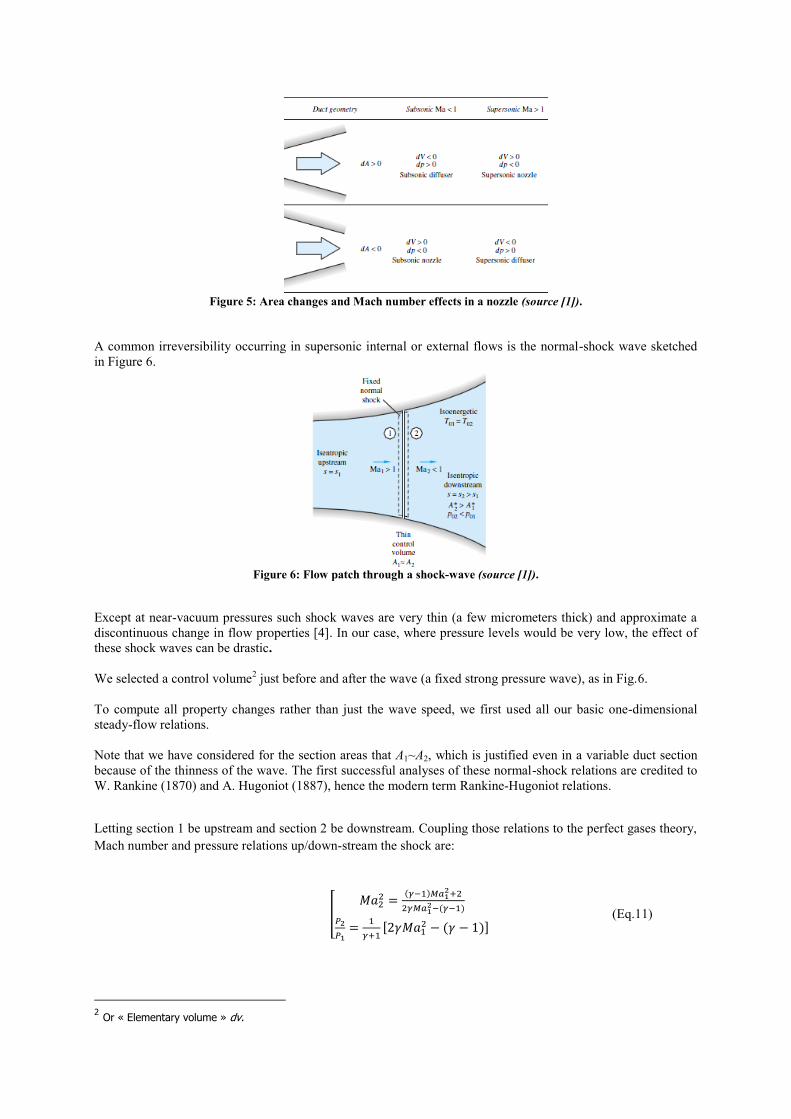
Figure 5: Area changes and Mach number effects in a nozzle (source [1]).
A common irreversibility occurring in supersonic internal or external flows is the normal-shock wave sketched
in Figure 6.
Figure 6: Flow patch through a shock-wave (source [1]).
Except at near-vacuum pressures such shock waves are very thin (a few micrometers thick) and approximate a
discontinuous change in flow properties [4]. In our case, where pressure levels would be very low, the effect of
these shock waves can be drastic.
We selected a control volume2 just before and after the wave (a fixed strong pressure wave), as in Fig.6.
To compute all property changes rather than just the wave speed, we first used all our basic one-dimensional
steady-flow relations.
Note that we have considered for the section areas that A1~A2, which is justified even in a variable duct section
because of the thinness of the wave. The first successful analyses of these normal-shock relations are credited to
W. Rankine (1870) and A. Hugoniot (1887), hence the modern term Rankine-Hugoniot relations.
Letting section 1 be upstream and section 2 be downstream. Coupling those relations to the perfect gases theory,
Mach number and pressure relations up/down-stream the shock are:
(Eq.11)
2 Or « Elementary volume » dv.
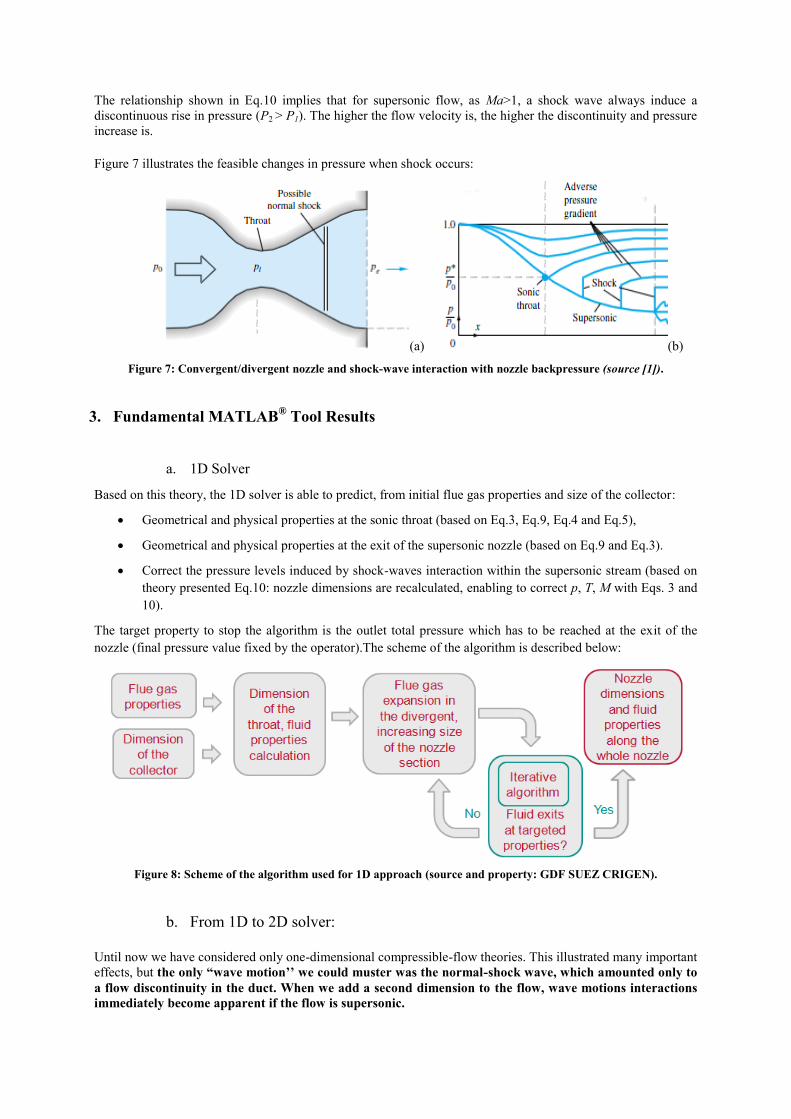
The relationship shown in Eq.10 implies that for supersonic flow, as Ma>1, a shock wave always induce a
discontinuous rise in pressure (P2 > P1). The higher the flow velocity is, the higher the discontinuity and pressure
increase is.
Figure 7 illustrates the feasible changes in pressure when shock occurs:
(a) (b)
Figure 7: Convergent/divergent nozzle and shock-wave interaction with nozzle backpressure (source [1]).
3. Fundamental MATLAB® Tool Results
a. 1D Solver
Based on this theory, the 1D solver is able to predict, from initial flue gas properties and size of the collector:
Geometrical and physical properties at the sonic throat (based on Eq.3, Eq.9, Eq.4 and Eq.5),
Geometrical and physical properties at the exit of the supersonic nozzle (based on Eq.9 and Eq.3).
Correct the pressure levels induced by shock-waves interaction within the supersonic stream (based on
theory presented Eq.10: nozzle dimensions are recalculated, enabling to correct p, T, M with Eqs. 3 and
10).
The target property to stop the algorithm is the outlet total pressure which has to be reached at the exit of the
nozzle (final pressure value fixed by the operator).The scheme of the algorithm is described below:
Figure 8: Scheme of the algorithm used for 1D approach (source and property: GDF SUEZ CRIGEN).
b. From 1D to 2D solver:
Until now we have considered only one-dimensional compressible-flow theories. This illustrated many important
effects, but the only “wave motion’’ we could muster was the normal-shock wave, which amounted only to
a flow discontinuity in the duct. When we add a second dimension to the flow, wave motions interactions
immediately become apparent if the flow is supersonic.
The 2D Matlab® tool builds a hexa-uniform mesh from the nozzle profile deduced from 1D solver results. The
fast algorithm solves all the Euler equations (continuity, momentum, energy and equation of state) for each
cell of the mesh. It enables to resolve the modification of flow parameters in the radial direction.
c. Hypotheses
Simplified hypotheses used for flue gas were chosen in this first assessment study of the ICES system:
perfect gases,
composition (molar) 85%N2 15%CO2,
inlet pressure: 2 bara,
inlet temperature: 26°C,
mass flow rate: 80 kg/s.
The size of the diameter cylindrical section before the convergent part of the nozzle, where these flue gases are
collected, was set at 1.5m.
The higher targeted pressure was chosen at 0.07 bara at the exit of the nozzle that has to be determined by the
tool.
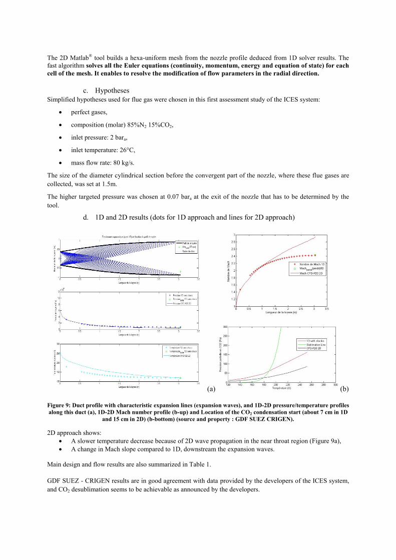
d. 1D and 2D results (dots for 1D approach and lines for 2D approach)
(a) (b)
Figure 9: Duct profile with characteristic expansion lines (expansion waves), and 1D-2D pressure/temperature profiles
along this duct (a), 1D-2D Mach number profile (b-up) and Location of the CO2 condensation start (about 7 cm in 1D
and 15 cm in 2D) (b-bottom) (source and property : GDF SUEZ CRIGEN).
2D approach shows:
A slower temperature decrease because of 2D wave propagation in the near throat region (Figure 9a),
A change in Mach slope compared to 1D, downstream the expansion waves.
Main design and flow results are also summarized in Table 1.
GDF SUEZ - CRIGEN results are in good agreement with data provided by the developers of the ICES system,
and CO2 desublimation seems to be achievable as announced by the developers.
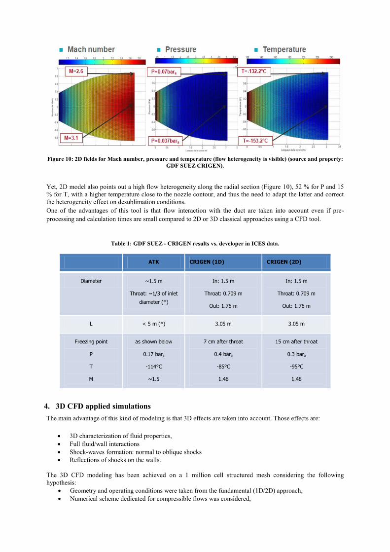
Figure 10: 2D fields for Mach number, pressure and temperature (flow heterogeneity is visible) (source and property:
GDF SUEZ CRIGEN).
Yet, 2D model also points out a high flow heterogeneity along the radial section (Figure 10), 52 % for P and 15
% for T, with a higher temperature close to the nozzle contour, and thus the need to adapt the latter and correct
the heterogeneity effect on desublimation conditions.
One of the advantages of this tool is that flow interaction with the duct are taken into account even if pre-
processing and calculation times are small compared to 2D or 3D classical approaches using a CFD tool.
Table 1: GDF SUEZ - CRIGEN results vs. developer in ICES data.
ATK CRIGEN (1D) CRIGEN (2D)
Diameter ~1.5 m
Throat: ~1/3 of inlet
diameter (*)
In: 1.5 m
Throat: 0.709 m
Out: 1.76 m
In: 1.5 m
Throat: 0.709 m
Out: 1.76 m
L < 5 m (*) 3.05 m 3.05 m
Freezing point
P
T
M
as shown below
0.17 bara
-114°C
~1.5
7 cm after throat
0.4 bara
-85°C
1.46
15 cm after throat
0.3 bara
-95°C
1.48
4. 3D CFD applied simulations
The main advantage of this kind of modeling is that 3D effects are taken into account. Those effects are:
3D characterization of fluid properties,
Full fluid/wall interactions
Shock-waves formation: normal to oblique shocks
Reflections of shocks on the walls.
The 3D CFD modeling has been achieved on a 1 million cell structured mesh considering the following
hypothesis:
Geometry and operating conditions were taken from the fundamental (1D/2D) approach,
Numerical scheme dedicated for compressible flows was considered,

Steady and unsteady simulations were achieved.
CFD tool provided sharp characterization of the flow behavior in the supersonic nozzle. In particular, it
highlighted the strong heterogeneity of pressure, temperature and Mach number profile in the flow, induced by
“3D effects”, such as wave interactions between them and with the nozzle walls.
Figure 11: Temperature field and 3D waves in the nozzle (source and property: GDF SUEZ CRIGEN)
3D results are then compared to previous results and are in good agreement with experimental data
too.
Table 2: CRIGEN global results vs developer in ICES data.
As said before, this kind of modeling can take into account 3D effects such as shock waves' reflections that may
occur in the supersonic duct (Fig. 12).
Figure 12 : Mean axial temperature field (left), temperature (middle) and pressure (right) profiles along the duct on
the axis (red line),and 0.3m away from the axis (blue line) (source and property: GDF SUEZ CRIGEN).
.
5. Conclusions
Authors have initiated the assessment of an innovative low-temperature supersonic CO2 capture by the use of
numerical modeling.
GDF SUEZ - CRIGEN expertise was able to develop a powerful and flexible tool to study the:
Design a nozzle able to treat a certain mass flow rate of flue gases,
Fluid properties evolution in the divergent part of the nozzle,
Location in the nozzle where the phase change (liquid or solid) of one of the flue gases components
may occur (here CO2).
This tool is able to model quickly major relevant phenomena present in the low-temperature capture processes,
and in particular it isolated and pointed out the effect of shock waves on flue gas pressure and temperature, and
thus on desublimation condition.
However main improvement to these models would be to implement respectively mean and local desublimation /
condensation process (including the released latent heat and the changing gas / solid mass balance along the
profile in the equation).
Both fundamental and applied (3D CFD) results are in good agreement with data provided by ICES developers,
and desublimation conditions for a 90% CO2 capture rate seem achievable (particularly low temperature levels
predicted in 3D), as targeted by these developers.
References
[1] Anderson, J. (2007). Fundamentals of Aerodynamics, Fourth Edition. New York: McGraw-Hill
Education.
[2] Anderson, J. (2003). Modern Compressible Flow with Historical Perspective. New York: McGraw-Hill
Higher Education.
[3] Anderson, J. (2001). Research in Supersonic Flight and the Breaking of the Sound Barrier. Retrieved
September 30, 2009, from Engineering Science to Big Science.
[4] Henry, J., Dick, S., & Garber, S. (2007, March 26). Orders of Magnitude: A History of the NACA and
NASA, 1915 - 1990. Retrieved June 4, 2009, from The NASA History.
Suggest adding these references:
http://www.sciencedirect.com/science/article/pii/S1359431111004170
http://onlinelibrary.wiley.com/doi/10.1002/zamm.19580381124/abstract
https://www.princeton.edu/mae/people/faculty/miles/rmdocs/Conference%20Proceedings/2000_
AIAADenver-2379-Erbland.pdf
Figure references:
i (2012) http://www.netl.doe.gov/File%20Library/Events/2012/CO2%20Capture%20Meeting/A-
Castrogiovanni-ACENT-ICES.pdf
ii (2014) http://www.netl.doe.gov/File%20Library/Events/2014/2014%20NETL%20CO2%20Capture/A-
Castrogiovanni-ATK-Supersonic-Post-Combustion.pdf.