STANDARDS - DTIC
165
TECHNOLOGY TRANSFER PROGRAM (TTP) FINAL REPORT STANDARDS STANDARDS VOLUME 2 APPENDICES Prepared by: Livingston Shipbuilding Company in conjunction with: IHI Marine Technology, Inc. June 30, 1981
Transcript of STANDARDS - DTIC

TECHNOLOGY TRANSFER PROGRAM (TTP)
FINAL REPORT
STANDARDS
STANDARDSVOLUME 2 APPENDICES
Prepared by:
Livingston Shipbuilding Companyin conjunction with:IHI Marine Technology, Inc.
June 30, 1981

Report Documentation Page Form ApprovedOMB No. 0704-0188
Public reporting burden for the collection of information is estimated to average 1 hour per response, including the time for reviewing instructions, searching existing data sources, gathering andmaintaining the data needed, and completing and reviewing the collection of information. Send comments regarding this burden estimate or any other aspect of this collection of information,including suggestions for reducing this burden, to Washington Headquarters Services, Directorate for Information Operations and Reports, 1215 Jefferson Davis Highway, Suite 1204, ArlingtonVA 22202-4302. Respondents should be aware that notwithstanding any other provision of law, no person shall be subject to a penalty for failing to comply with a collection of information if itdoes not display a currently valid OMB control number.
1. REPORT DATE 30 JUN 1981
2. REPORT TYPE N/A
3. DATES COVERED -
4. TITLE AND SUBTITLE Technology Transfer Program (TTP) Standards Volume 2 Appendices
5a. CONTRACT NUMBER
5b. GRANT NUMBER
5c. PROGRAM ELEMENT NUMBER
6. AUTHOR(S) 5d. PROJECT NUMBER
5e. TASK NUMBER
5f. WORK UNIT NUMBER
7. PERFORMING ORGANIZATION NAME(S) AND ADDRESS(ES) Naval Surface Warfare Center CD Code 2230 - Design Integration ToolsBuilding 192 Room 128-9500 MacArthur Blvd Bethesda, MD 20817-5700
8. PERFORMING ORGANIZATIONREPORT NUMBER
9. SPONSORING/MONITORING AGENCY NAME(S) AND ADDRESS(ES) 10. SPONSOR/MONITOR’S ACRONYM(S)
11. SPONSOR/MONITOR’S REPORT NUMBER(S)
12. DISTRIBUTION/AVAILABILITY STATEMENT Approved for public release, distribution unlimited
13. SUPPLEMENTARY NOTES
14. ABSTRACT
15. SUBJECT TERMS
16. SECURITY CLASSIFICATION OF: 17. LIMITATION OF ABSTRACT
SAR
18. NUMBEROF PAGES
164
19a. NAME OFRESPONSIBLE PERSON
a. REPORT unclassified
b. ABSTRACT unclassified
c. THIS PAGE unclassified
Standard Form 298 (Rev. 8-98) Prescribed by ANSI Std Z39-18
APPENDIX
A
B
c
D
E
F
G
TABLE OF CONTENTS
SUBJECT
STANDARDIZATION AND MODULARIZATION INSHIPBUILDING
JIS GROUP F
IHI INDEX
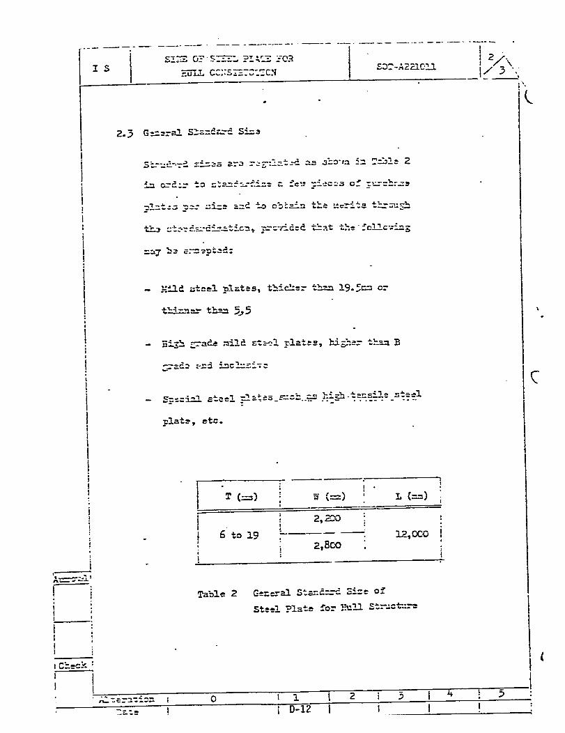
EXAMPLES OF IHI STANDARDS - SOT A221XXXHULL STRUCTURE MATERIAL APPLICATION
EXAMPLE OF IHI STANDARDS - SOT B5XXXXX
EXAMPLE OF IHI STANDARDS IN USE
LIVINGSTON STANDARD OPERATION PROCEDURE“INITIATION, REVIEW, AND ISSUANCE OFLIVINGSTON STANDARDS”
PAGE NO.
A-1
B-1
c-1
D-1
E-1
F-1
G-1

APPENDIX A
STANDARDIZATION
AND
MODULARIZATION IN SHIPBUILDING
October 27-31, 1980
STANDARDIZATION AND MODULARIZATION IN SHIPBUILING
y. Ichinose
IHI Marine Technology, Inc.
Department of Naval Architectureand Marine Engineeringcollege of Engineering
The university of MichiganAnn Arbor, Michigan 48109
CONTENTS
II
III.
Iv.
v.
VI.
INTRODUCTION . . . . . . . . . . . . . . . . . . . . . . . . . . . . . . . . . . . . . . . . . . . . . . . . .
BASIC CONCEPT OF STANDARDS AND MODULES . . . . . . . . . . . . . . . . . . . . . . .
STANDARDIZATION IN THE JAPANESE SHIPBUILDING INDUSTRY . . . . . . . .
PRoCZDURE8 OF STANDARDIZATION AND MODULAiZATION . . . . . . . . . . . . .
TYPICAL APPLICATIONS OF STANDARDS AND MODULES . . . . . . . . . . . . . . . .
5-1. “ “Basic Design . . . . . . . . . . . . . . . . . . . . . . . . . . . . . . . . . . . . . . . . . . .
5-2. Detail Design . . . . . . . . . . . . . . . . . . . . . . . . . . . . . . . . .- . . . . . . . .
5-3. Material Purchasing . . . . . . . . . . . . . . . . . . .- . . . . . . . . . . . . .- . .
5-4. Production . . . . . . . . . . - . . . . . . . . . . . . . . . . . . . . . . . . . - . . . . . . . .
5-5. Computerization . . . . . . . . . . . . . . . . . . . . . . . . . . . . . . . . . . . . . . . .
ADVANTAGES OF STANDIZATION AND MODULARIZAT1ON . . . . . . . . . . . . .
.
A P ”
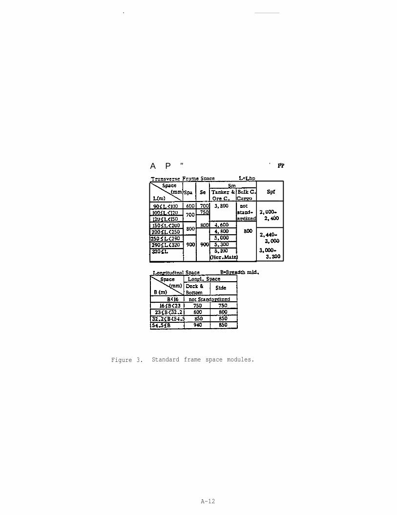
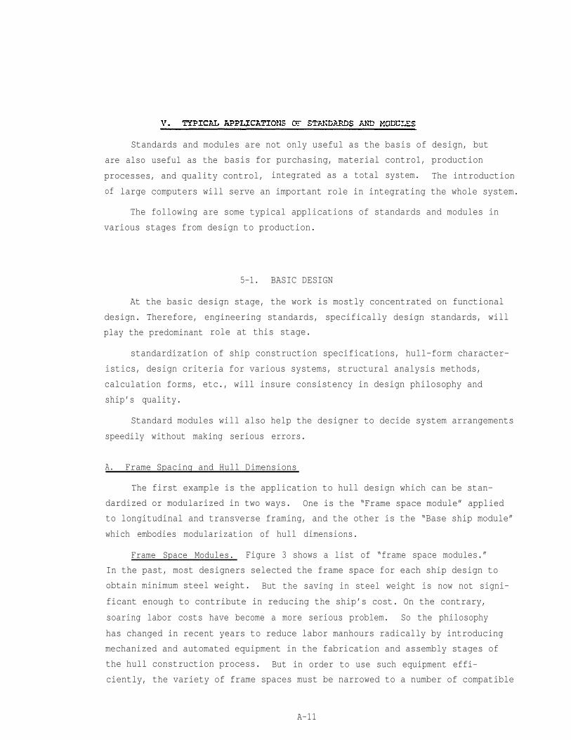
Figure 3. Standard frame space modules.
A-12

But , in spite of these obstacleks,
but steadily, to introduce standarixation into shipbuildinq. Looking
through the past record of SNAME's, it is very interesting to dis-
giring them nicknames like “Ford ships,” “Buick Ships,l’ Dodge ships,’'and
so on.
This concept of stancdard ships did come to realization in the two Wcrld
Wars, especially during World War II when the United States played the major
role in mass-producing thousands of freighters and tankers, well known as
“Liberty ships,” “Victory ships,” and “T2’s”. Japan also produced series of
“wartime standard ships,” ranging up to 10,O00 DWT. These ships were highly
rationalized in design and were mass-produced simultaneously in several ship-
yards to fulfil the huge demand of tonnage required in wartime transportation.
But after the war, the concept of standard ships gradually receded. The
requirements for individual ship designs became so diversified and sophisti-
cated that the shipbuilder had to retreat to the traditional “tailored” design
to satisfy the various requirements of their clients. But in the early
1960’s, the booming demand for new ship construction offered a good opportunity
to the shipbuilders to reintroduce standardization to rationalize and improve
their productivity.
Naturally, the standardization started from components and then expanded
to modular units, systems, and eventually to whole ship designs.
In the late 1960’s, most leading European and Japanese shipyards presented
series of standard ships, mostly tankers, bulk carriers, and multi-purpose
cargo ships, into the market. But since the oil crisis, triggered by the
Suez War in 1973, a deep depression in the shipping market again reduced the
demand for standard ships.
It is quite obvious that standard ships will be meaningless to the ship
yard unless they have sufficient orders to build them continuously in series.
But this does not mean that standardization must be wiped out from ship-
building. Irrespective of the ship’s type, size, or sophistication, there
are many components, equipment groups, or systems which still have similar
or common features that could be standardized or modularized.
A-2
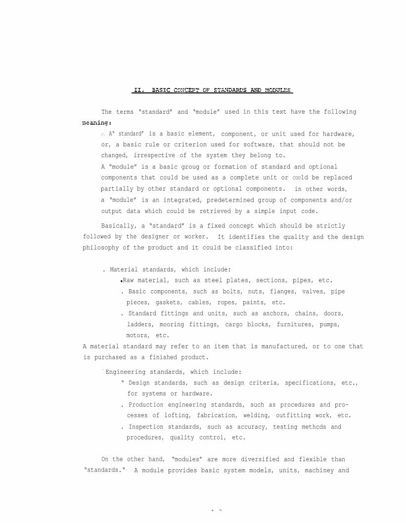
The terms “standard” and “module” used in this text have the following
.-. A“ standard” is a basic element, component, or unit used for hardware,
or, a basic rule or criterion used for software, that should not be
changed, irrespective of the system they belong to.
A “module” is a basic groug or formation of standard and optional
components that could be used as a complete unit or COUld be replaced
partially by other standard or optional components. in other words,
a “module” is an integrated, predetermined group of components and/or
output data which could be retrieved by a simple input code.
Basically, a “standard” is a fixed concept which should be strictly
followed by the designer or worker. It identifies the quality and the design
philosophy of the product and it could be classified into:
. Material standards, which include:
● Raw material, such as steel plates, sections, pipes, etc.
. Basic components, such as bolts, nuts, flanges, valves, pipe
pieces, gaskets, cables, ropes, paints, etc.
. Standard fittings and units, such as anchors, chains, doors,
ladders, mooring fittings, cargo blocks, furnitures, pumps,
motors, etc.
A material standard may refer to an item that is manufactured, or to one that
is purchased as a finished product.
- Engineering standards, which include:
“ Design standards, such as design criteria, specifications, etc.,
for systems or hardware.
. Production engineering standards, such as procedures and pro-
cesses of lofting, fabrication, welding, outfitting work, etc.
. Inspection standards, such as accuracy, testing methcds and
procedures, quality control, etc.
On the other hand, “modules” are more diversified and flexible than
“standards.“ A module provides basic system models, units, machiney and
A 3


The Japanese shipbuilding industry fully realized the necessity of
establishing shipbuilding standards in the late 1940’s when Japanese ship-
builders began to revive and strengthen their shipbuilding capacity. Under
the auspices of the Society of Naval Architects of Japan, (SNAJ) , the major
shipyards jointly formed several working groups and committees to establish
design standards, hull construction standards, outfitting standards, testing
and inspecticn standards, etc., as a common basis for design and production.
In parallel, national marine standards were established by the Japan Marine
Standards Association in coordination with the shipbuilding and pertinent
marine industries, and the standards thus established formed part of the
Japanese industrial Standard (JIS), enacted by the Ministry of TransPort.
JIS standards cover various marine camponents, equipment, machinery, electric
and electronic appliances, test procedures, etc., as well as materials and
components that could be used in common with other industries.
Marine JIS standards are classified into the following:
● Fittings (about 190 items), covering Varios mooring fittings,
anchors, anchor cables, davits, derricks, hatch covers, manholes,
steel doors, round scuttles, windows, ventilators, ladders, life
boats and davits, galley equipment, pipe fittings, cargo blocks,
navigation equipments, etc.
● Engines and Valves (about 190 items), covering design criteria,
material specifications, and test codes for various machinery,
instruments, valves, strainers, filters, pipe flanges and joints,
tools, etc.
. Electric Appliances & Navigational Instruments (about 110 items),
covering various electric lamps, lights, projectors, batteries,
signal lamps, engine telegraphs, switches, distribution boards,
etc.
These JIS standard fittings and components are manufactured by specialized
manufacturers in accordance with JIS specifications and, after testing and type
approval, these manufacturers are authorized to distribute their products
stamped with a “JIS” mark.
A-5

In addition to these national standards and volunatory consensus standards
of the marine industry, most shipyards have established their own supplementary
.standards in areas which are not covered by the former two categories, mainly,
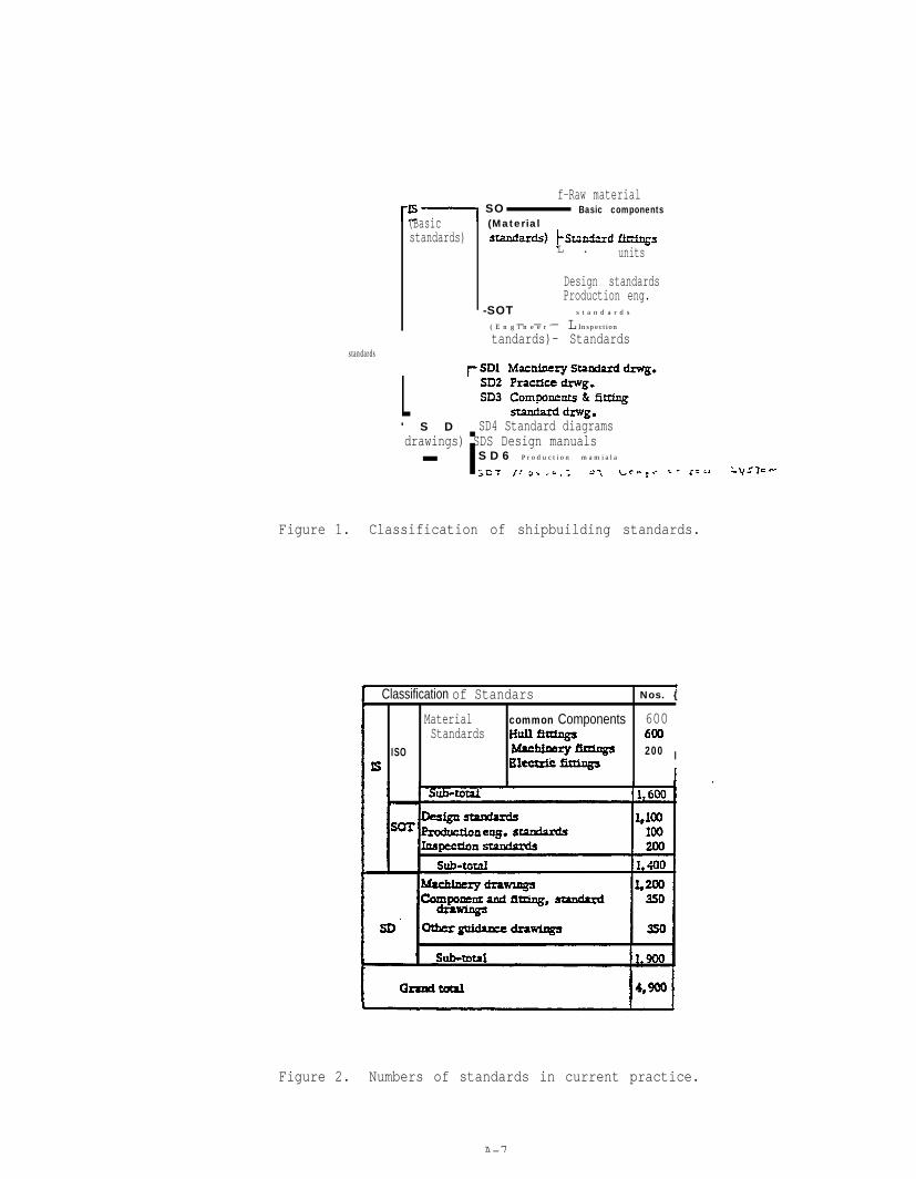
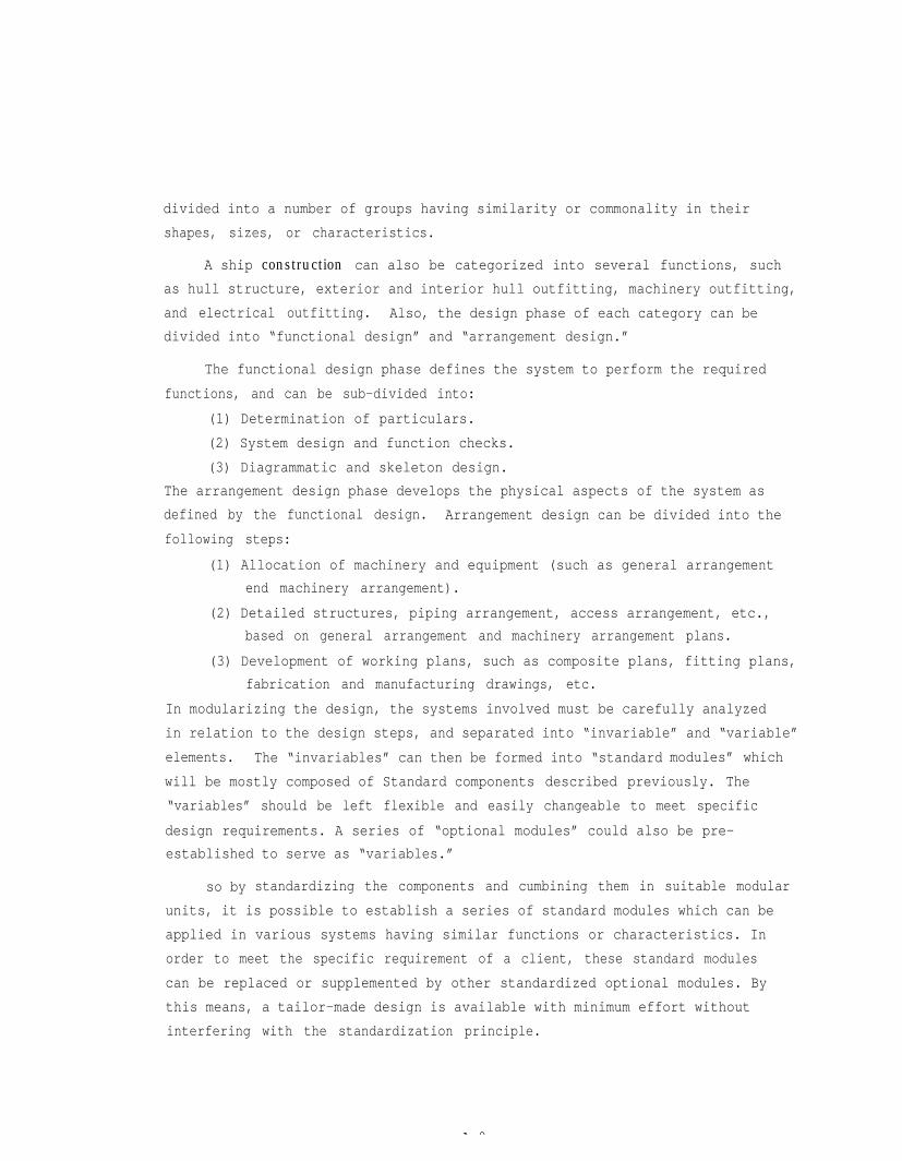
to rationalize product%on processes and facilities. Figure 1 shows a sampleof in-house standards currently adopted by IHI.
These standards are basically organized into two main categories: "IS,"
which are “Basic Standards,” and “SD,” which are the “Standard Drawings.”
“IS” includes basic standards which must be strictly obeyed by the
designers or the workers, and is further divided into “Material standards (SO)”
and Engineering standards (SOT).”
In addition to the “IS” basic standards,, ”SD” provides the standard or
guidance drawings for machinery and outfitting layouts, basic system modules,
manuals and practices, etc., which can be utilized in routine design and pro-
duction work. Besides the basic modules, “SD” allows some flexibility in
application to meet individual requirements. Figure 2 shows the number of
standards currently adopted in IHI*s shipbuilding operation.
These standards are controlled and up-dated by special control groups .
in tile design department. Up-dating is mainly based on feedback from semice
engineers aboard ships during the guarantee period, and also from the produc-
tion line for improvement in productivity.
The number of standards is kept to a minimum by identifying and cancel-
ing those which are found to be obsolete or not worth keeping.
A-6
(Basicstandards)
f-Raw materialSO Basic components(Material
L . units
Design standards
- - - L
Production eng.-SOT s t a n d a r d s
( E n g i n e e r ' Inspection
tandards)- Standardsstandards
L- i
' S D SD4 Standard diagramsdrawings) SDS Design manuals
S D 6 P r o d u c t i o n m a m i a l a
Figure 1. Classification of shipbuilding standards.
Classification of Standars Nos. {
Material common Components 600 Standards
ISO 200 I
4,900
Figure 2. Numbers of standards in current practice.
A-7

Standardization--. . is 2 tedious and cumbersome job that requires full inves-
tigation of the ships’ systems and their features to establish good and useful
Standards. In a sense, “standards” are often misconceived as “cheap and poor
quality” products, but this is not the way “standards” should be established.
Standard materials should be of high quality and durable to assure a trouble-
free and reliable product. The performance of these standards should be
observed incessantly and improved or updated to debug any defects or to keep
up with the state-of-the-art. It is also imporant to keep the number of
standards to a minimum.
The first step to standardization is to identify basic material, compo-
nents, and fittings that are commonly used in all types of ships. Most raw
material specifications are specified by national standards or classification
society rules, so it is only necessary to standardize sizes or thicknesses,
based on manufacturers' standard market products, considering the frequency
of usage, shop facilities, storage, etc. Canponents or fittings that are
standardized end readily available in the market can be used directly as
in-house standards. This concept can also be extended to basic machinery or
equipment, such as pumps, motors, lifeboats, hatch covers, etc., selected
from makers’ standard models which are proven to be reliable from past experi-
ence. In this case, at least two manufacturers’ models of similar character-
istics should be selected to allow flexibility in purchasing.
Standards for design and engineering should be systematized and catego-
rized into systems and/or production processes. Standard specifications and
calculation formulae or sheets can be used to unify the design criteria,
quality, functions, and work practices of the systems. Supplementary data
and manuals to support these standards are also necessary to identify the
rationale of the standardized“ items. This assists the user in understanding
the logic of the various standards, and in extrapolating to applications
which are beyond the standards. The next step is to expand these standards
into modules.
The ship’s hardware consists of numerous systems involving thousands of
structural and mechanical components. But most of these cmnponents can be
A-8
divided into a number of groups having similarity or commonality in their
shapes, sizes, or characteristics.
A ship construction can also be categorized into several functions, such
as hull structure, exterior and interior hull outfitting, machinery outfitting,
and electrical outfitting. Also, the design phase of each category can be
divided into “functional design” and “arrangement design.”
The functional design phase defines the system to perform the required
functions, and can be sub-divided into:
(1) Determination of particulars.
(2) System design and function checks.
(3) Diagrammatic and skeleton design.
The arrangement design phase develops the physical aspects of the system as
defined by the functional design. Arrangement design can be divided into the
following steps:
(1) Allocation of machinery and equipment (such as general arrangement
end machinery arrangement).
(2) Detailed structures, piping arrangement, access arrangement, etc.,
based on general arrangement and machinery arrangement plans.
(3) Development of working plans, such as composite plans, fitting plans,
fabrication and manufacturing drawings, etc.
In modularizing the design, the systems involved must be carefully analyzed
in relation to the design steps, and separated into “invariable” and “variable”
elements. The “invariables” can then be formed into “standard modules” which
will be mostly composed of Standard components described previously. The
“variables” should be left flexible and easily changeable to meet specific
design requirements. A series of “optional modules” could also be pre-
established to serve as “variables.”
so by standardizing the components and cumbining them in suitable modular
units, it is possible to establish a series of standard modules which can be
applied in various systems having similar functions or characteristics. In
order to meet the specific requirement of a client, these standard modules
can be replaced or supplemented by other standardized optional modules. By
this means, a tailor-made design is available with minimum effort without
interfering with the standardization principle.
A 9

This way of standardization has been successfully applied in the auto-
mobile industry. In buying a new car, one can select the style among
Several brands using the same chassis, two doors or four doors, V6 or V8
engine, manual or automatic transmission, interior and exterior finishings,
power windows, remote locks, AM/PM radios, stereos, etc.
A 10
Standards and modules are not only useful as the basis of design, but
are also useful as the basis for purchasing, material contro1, production
processes, and quality control, integrated as a total system. The introduction
of large computers will serve an important role in integrating the whole system.
The following are some typical applications of standards and modules in
various stages from design to production.
5-1. BASIC DESIGN
At the basic design stage, the work is mostly concentrated on functional
design. Therefore, engineering standards, specifically design standards, will
play the predominant role at this stage.
standardization of ship construction specifications, hull-form character-
istics, design criteria for various systems, structural analysis methods,
calculation forms, etc., will insure consistency in design philosophy and
ship’s quality.
Standard modules will also help the designer to decide system arrangements
speedily without making serious errors.
A. Frame Spacing and Hull Dimensions
The first example is the application to hull design which can be stan-
dardized or modularized in two ways. One is the “Frame space module” applied
to longitudinal and transverse framing, and the other is the “Base ship module”
which embodies modularization of hull dimensions.
Frame Space Modules. Figure 3 shows a list of “frame space modules.”
In the past, most designers selected the frame space for each ship design to
obtain minimum steel weight. But the saving in steel weight is now not signi-
ficant enough to contribute in reducing the ship’s cost. On the contrary,
soaring labor costs have become a more serious problem. So the philosophy
has changed in recent years to reduce labor manhours radically by introducing
mechanized and automated equipment in the fabrication and assembly stages of
the hull construction process. But in order to use such equipment effi-
ciently, the variety of frame spaces must be narrowed to a number of compatible
A-11

.
A P ”
Figure 3. Standard frame space modules.
A-12
modules.
Of course, in selecting the frame space modules, the influence on hull
Steel weight has to be carefully analyzed to restrain the weight increase to
minimum. Also, the influence on outfitting, such as layout of cabins, pipe
and cable ducts, etc., should be checked to assure that adequate space or
accessibility is available by using the standard frame spaces.
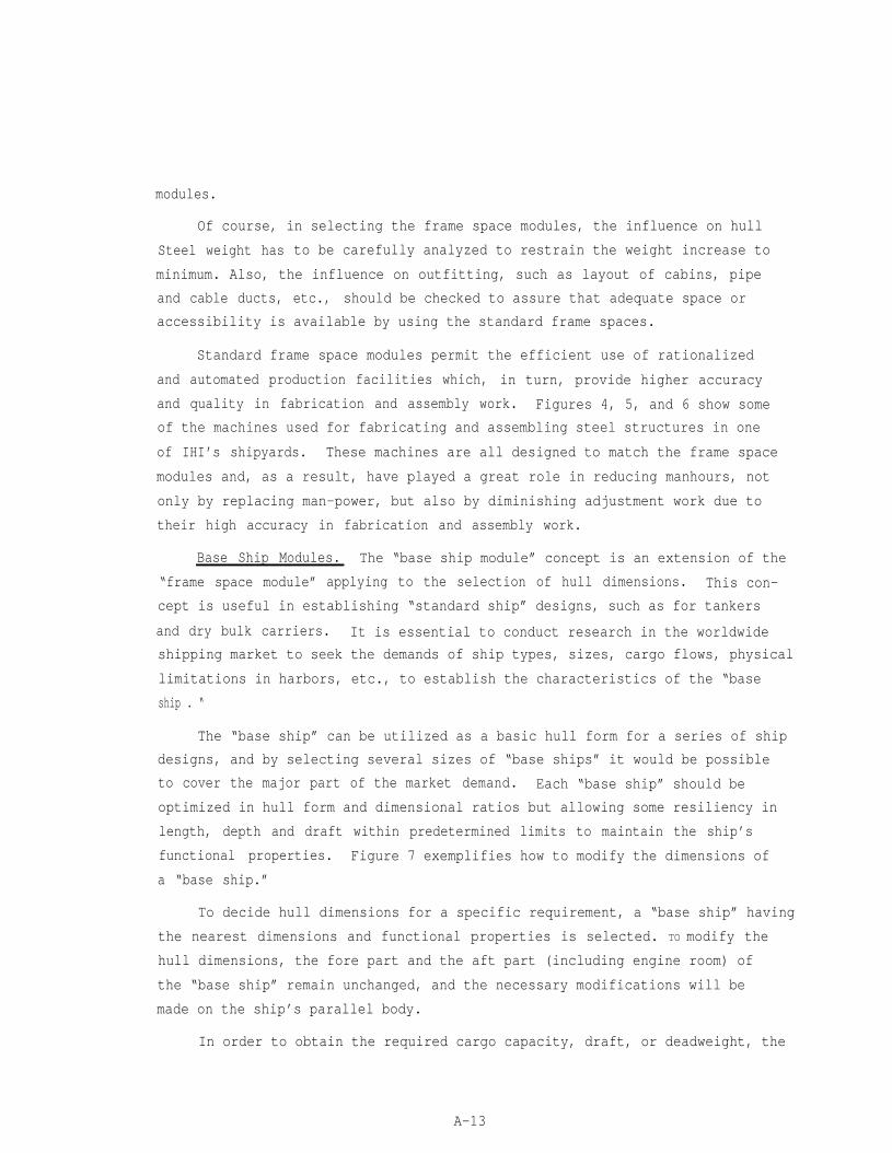
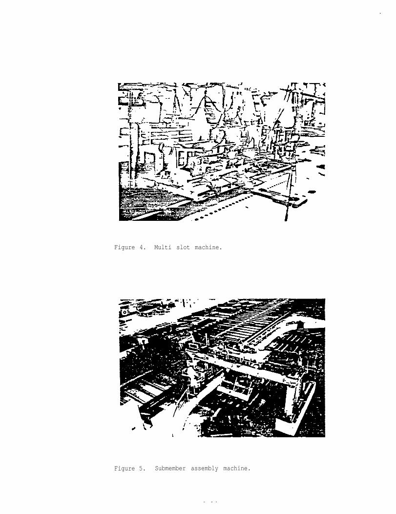
Standard frame space modules permit the efficient use of rationalized
and automated production facilities which, in turn, provide higher accuracy
and quality in fabrication and assembly work. Figures 4, 5, and 6 show some
of the machines used for fabricating and assembling steel structures in one
of IHI’s shipyards. These machines are all designed to match the frame space
modules and, as a result, have played a great role in reducing manhours, not
only by replacing man-power, but also by diminishing adjustment work due to
their high accuracy in fabrication and assembly work.
Base Ship Modules. The “base ship module” concept is an extension of the
“frame space module” applying to the selection of hull dimensions. This con-
cept is useful in establishing “standard ship” designs, such as for tankers
and dry bulk carriers. It is essential to conduct research in the worldwide
shipping market to seek the demands of ship types, sizes, cargo flows, physical
limitations in harbors, etc., to establish the characteristics of the “base
ship . “
The “base ship” can be utilized as a basic hull form for a series of ship
designs, and by selecting several sizes of “base ships” it would be possible
to cover the major part of the market demand. Each “base ship” should be
optimized in hull form and dimensional ratios but allowing some resiliency in
length, depth and draft within predetermined limits to maintain the ship’s
functional properties. Figure 7 exemplifies how to modify the dimensions of
a “base ship.”
To decide hull dimensions for a specific requirement, a “base ship” having
the nearest dimensions and functional properties is selected. TO modify the
hull dimensions, the fore part and the aft part (including engine room) of
the “base ship” remain unchanged, and the necessary modifications will be
made on the ship’s parallel body.
In order to obtain the required cargo capacity, draft, or deadweight, the
A-13
.
Figure 4. Multi slot machine.
Figure 5. Submember assembly machine.
A 14

Figure 6. Longitudinal frame assembly machine.
Figure 7. Example of base ship modification.
ship’s length will be adjusted by adding or deducting multiples of transverse
frame space modules, and similarly, the ship’s depth will be adjusted by mul-
tiples of longitudinal frame space modules in the case of longitudinally
framed ships.
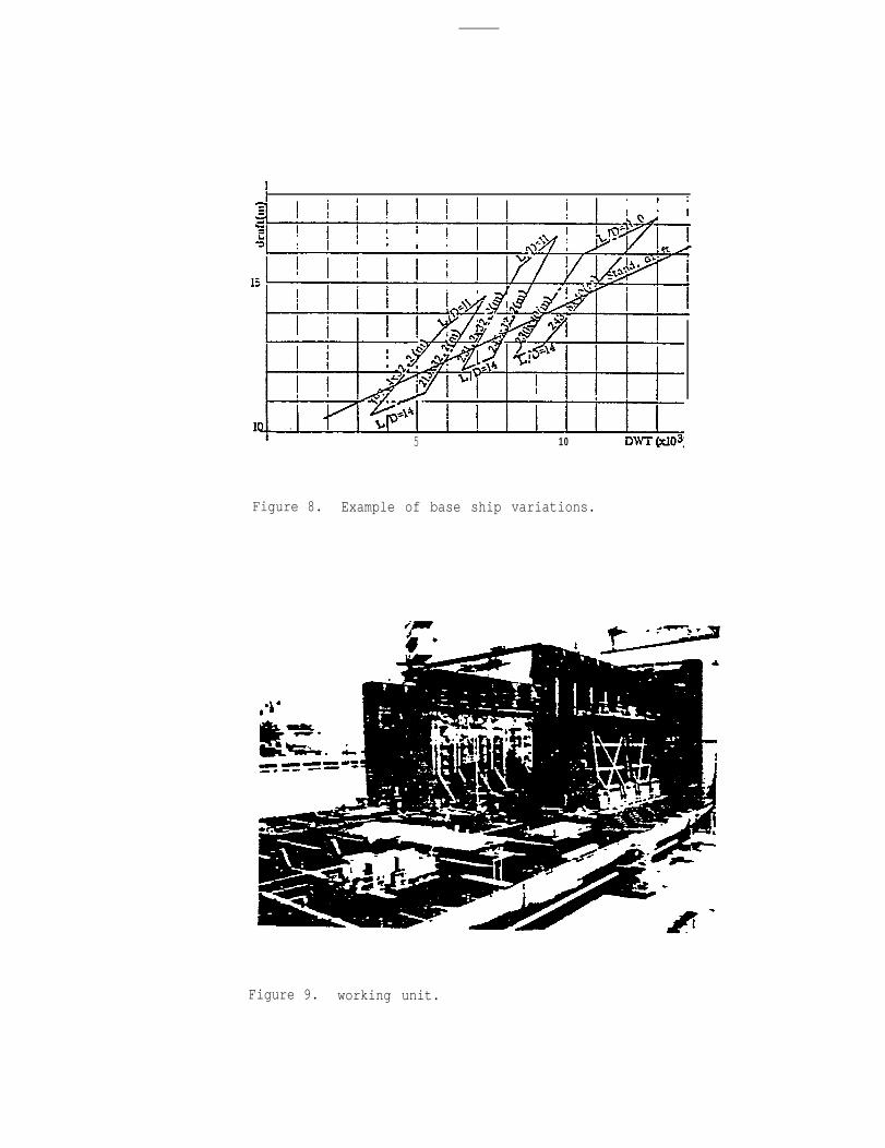
The limitations of extension or reduction of the ship’s length or
depth will be predetermined by checking the influence on the hull weight
and speed to avoid extraordinary deviations. Figure 8 shows a chart of the
typical base ship variation limits.
The cargo compartment will also be left interchangeable so that any
type of cargo section, such as for a tanker, ore carrier, or bulk
carrier, can be inserted. Figure 7 shows the base-ship tanker modified
to an ore carrier.
The midship section of the cargo compartment will be modularized to
match with the frame space module and the standard ship’s breadth, which
is usually limited by the breadth of the building berth or the building
dock. In other words, for a fixed ship’s breadth, the hatch breadth of a
bulk carrier or an ore carrier, or the disposition of longitudinal bulk-
heads of a tanker or an ore carrier, will remain unchanged irrespective
of the adjustment in the ship’s length or depth.
By adopting these base ship” modules, the designer can easily select
the required dimensions and cargo sections based on pre-studied data, so
there is no necessity to start from scratch. This permits great savings
in design work without impairing the ship’s functions.
At IHI, the advantage of "base ship” modules was enhanced by adopting
the “working unit” in hull erection work. Figure 9 shows a “working unit”
designed for work in the wing tanks of a standard VLCC. The “working unit”
is a mobile construction machine designed to incorporate hydraulic clamping
devices, automatic welding equipment, movable stages (or scaffolding), and
other necessary appliances required for hull erection. The unit is designed
to fit within the structural configuration of the “base ship”, and travels
on portable rails laid on the floor of the hull structure. The unit moves
lengthwise in accordance with a predetermined construction schedule so all
work must be completed and inspected before the unit moves to the next posi-
tion. Careful planning of production seqences and time scheduling is
A 16
5 10
Figure 8. Example of base ship variations.
Figure 9. working unit.
A 17

required for smooth and punctual operation.
By using these “working units”, the following advantages were obtained:
(1) All portable scaffolding in the cargo compartment could be omitted.
In the case of a VLCC, about 15,000 stage planks had been required.
(2) Working and production procedures, such as sub-dividing work zones,
and sequencing of fitting-welding-painting-inspection work flow, became
established. Also, production scheduling, material handling, work force
deployment, testing and inspection scheduling, etc., could be precisely
controlled.
(3) All work can be executed on safe-guarded platforms, so this safe
working environment led to improvements in productivity and quality.
B. Machinery Modules
When the engine power required for the propulsion plant has been
decided, the machinery designer starts planning its associated machinery,
piping systems, and their layout. The following are some examples of the
modules utilized in machinery design.
Propulsion Engine Particular Modules. The systems and ancillary
machinery pertinent to the type of main engine are virtually invariable.
Therefore, the particulars of pumps, heat exchangers, etc., can be pre-
determine d and standardized without interfering with other systems. Some
options could be left to meet specific requirements of the clients, such
as number of standby pumps, purifiers, and so on.
Figures 10 to 13 show examples of the particular module for propulsion
steam turbines with some of its pertinent ancillary machinery. Similar mod-
ules can also be established for diesel propulsion plants, classified by
engine types and ratings. All modules are stored in the computer data
bank, so when the main engine is selected, the designer can automatically
obtain all ancillary machinery particulars by simply inputting the key data
into the program.
Machinery Layout Modules. The physical arrangement of machinery and
equipment in the engine room will be laid out as soon as their particulars
are decided. Most of the machinery is grouped into systems, such as cooling
A-18
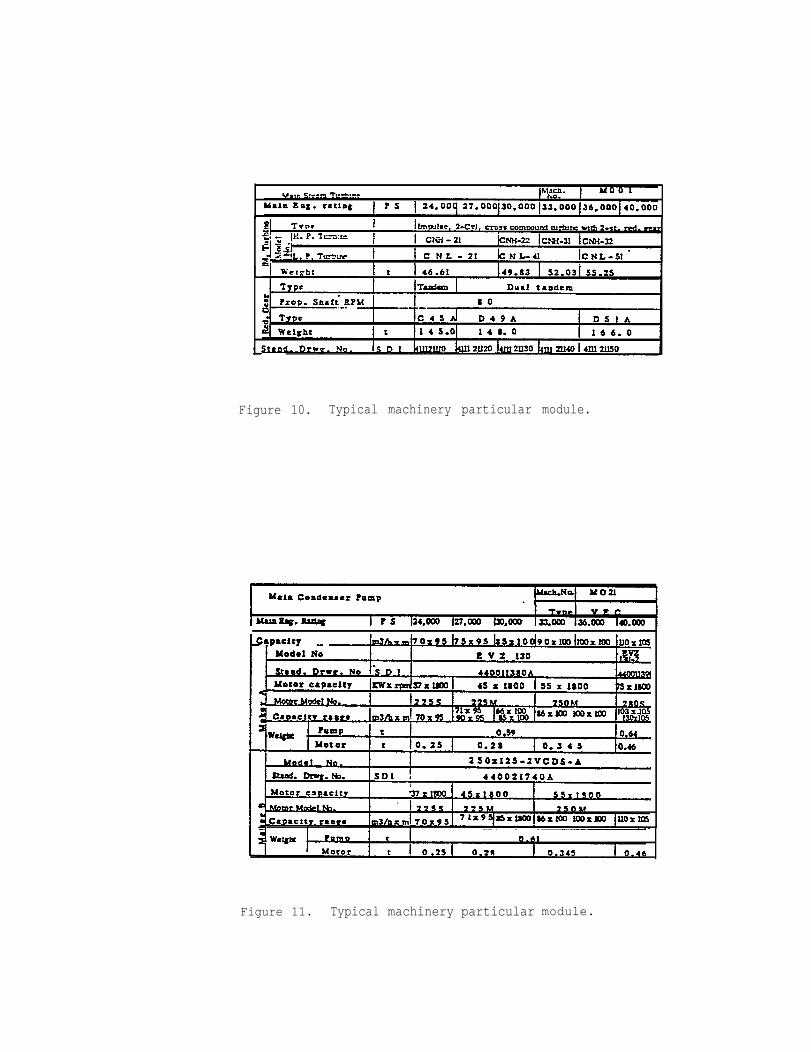
Figure 10. Typical machinery particular module.
Figure 11. Typical machinery particular module.

Figure 12. Typical machinery particular module.
Figure 13. Typical machinery particular module.
A-20
systems, fuel oil systems, L.o.
tate pre-outfitting in “units.”
These individual machinery
Systems, purifier systems, etc. , to facili-
units are standardized as basic modules.
The machinery arrangement of the engine room is designed by arranging these
individual modules considering the piping layout, accessibility for mainte-
nance and repairs, and margins for optional requirements. Figure 14 shows
part of the machinery layout module of a standard steam driven VLCC.
Modification of an engine room arrangement can be done simply by modi-
fying or replacing the basic modules. Figure 15 exemplifies a modification
by adding one drain pump without interfering with the arrangement of other
machinery .
Piping Layout Modules. Piping layout modules are developed either as
a complete system or a partial unit in connection with the machinery layout
modules. Figure 16 is the piping layout module corresponding to the machinery
layout module shown in Figure 14. Figure 17 is a partial piping layout
module of the drain tank and pumping system which was shown in Figure 15 (B),
consisting of one atmospheric drain tank, three drain pumps, piping and
instrumentation, assembled in one unit.
5-2. DETAIL DESIGN
The major work at the detail design stage is to convert the system-
oriented drawings developed at the basic design stage to zone-oriented
drawings. Systems are sub-divided into zones by composite drawings, and
work packages (or pallets) are grouped for each zone. Detailed manufacturing
drawings of larger machinery and/or outfitting modules are developed at this
stage for on-block outfitting by combining or modifying basic modules.
Figure 18 shows the actual unit module of Figure 17. These units are
accompanied with corresponding material lists which include the required
material data for the module. Material and components of each unit are sup-
plied to the workshop in pallets and assembled there into a camplete package.
“Patterns” and “Panels”
“Patterns” and “panels” are the terms used at IHI for basic modules of
A-21

Figure 14. Machinery arrangement module.
(A) Base Module
(B) Moduled Module
Figure 15. Modification of module.
One additional drain pump is
added in the modified module.

Figure 17. Pipe layout module.
Figure 18. Example of unit equipment.

Figure 16.Figure
Piping layout module
14.corresponding to the machinery layout module of

various systems. A “pattern” is a conceptual module, such as a partial
piping diagram of a system that could be applied to different sizes and
types of ships. For example, Figure 19 shows a “pattern” of the com-
on the main deck that matches the material
ordering zone. The “pattern” is further divided into “panels” which are
individual elementary modules of specific configurations, such as A, B and
C, and are composed of a group of standard components. Virtuallyr the
“panel” is an “invariable” module, but allowing selection in sizes and pipe
detailing and painting to conform with the specifications, and the “pattern”
is a “variable” module which could be modified by different combinations of
“panels”.
The “panel” includes an arrangement plan, a list of material size range,
quantities of standard fittings, complete descriptions of pipes and fittings,
standard guidance for pipe details and painting, etc., and is filed as the
shipyard’s standard. For a specific design, the designer retrieves this
information from the file, selects the sizes of standard fittings and pipes
and, if necessary, modifies the standard guidance to meet specifications
requirements, adds non-standard materials and, finally, incorporates them
in the material list.
Figure 20 shows patterns and panels of various systems
a composite plan of a specific
dimensions, spacing, etc., are
material list of the pallet is
work zone (pallet). At this
defined and entered into the
created.
integrated into
stager exact
drawings, and a
By using these patterns and panels, the detail design can be highly
rationalized and simplified. Various combinations of patterns and panels
of different systems can create machinery and piping layout modules as
previously described for utilization in basic design.
5-3. MATERIAL PURCHASING
Material purchasing is a function that plays an important role in acquir-
ing the required material for the ship’s construction and feeding it to the
production line at the appropriate time. Purchase orders and pertinent speci-
fications must be prepared and distributed to the subcontractor with proper
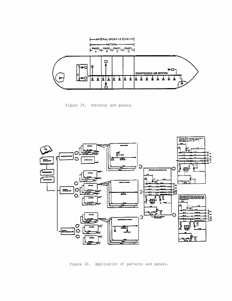
Figure 19. Patterns and panels.
Figure 20. Application of patterns and panels.

consideration of the production schedule and the lead time
manufacturing and delivery of the material. Also, efforts
to minimize stock so that the stockyards or warehouses are
with redundant material.
required for
must be made
not overstocked
Material purchasing is considered as part of the "planning” process,
wheareas purchase specifications and manufacturing drawings must be issued
by the design
scheduled and
Usually,
department. The issuance of these documents must be precisely
controlled to meet with the pallet schedules.
such work as preparation of purchase specifications, evaluation
of vendors’ proposals, etc., needs a long time before the orders are placed
and also requires a great deal of paper work to finalize the contract with
the vendors. The time and effort for these works can be considerably
reduced if these materials are pre-approved and filed as part of the ship-
yard’s standards.
For example, the Propulsion Engine Particular Module identifies the
ancillary machinery required for the propulsion machinery. In this case,
the machinery and equipment required for these modules could be pre-selected
from several standard catalogue models of competent vendors. These models
can be evaluated beforehand by extensive shop tests under shipyard super-
vision, and those eligible could be registered and filed as supplementary
shipyard “standards.” Specifications, drawings, test protocols, etc.,
could all be pre-approved by the shipyard. So, purchase orders can be
extremely simplified
stating the required
by issuing a standard purchase order format and simply
model number, quantity and delivery date to the vendor.
5-4. PRODUCTION
AS discussed previously, standardization and modularization will enhance
productivity by allowing automated fabrication or assembly machinery to be
introduced into the production line. Production scheduling and control can
be conducted more precisely and accurately by using statistical records of
standard work packages as yardsticks. Standard procedures and/or manuals for
welding, pipe fabrication, tolerance, quality assurance, etc., can be used by
both designers and workers and they could simplify instructions on individual
working drawings.
A-27
5-5. COMPUTERIZATION
The rapid progress of computer technology has led to wide application
of computers for design and production in the shipbuilding industry. Many
shipyards are now using computers for design calculations and analysis,
No machines for gas cutting and pipe fabrication, etc. Consequently, ship-
yards have reslized improved productivity and product quality. But the bene-
fits of computerization cannot be fully enjoyed unless the individual com-
puter processes from design to production are interfaced and integrated to
form a “total system.”
The total system interrelates design, material control, production,
scheduling, and accounting systems. Without standardization, this massive
system cannot be established rationally.
In order to file and process the massive data for an integrated system,
a large computer and sophisticated software become essential. But shipyards
which have little output capacity, or those who have to deal with a variety
of one-of-a-kind ships, may not be able to afford to apply full computer-
ization. But at least there are some systems or objects which can still be
standardized or modularized to suit small computers, and may provide some
benefit.
A-28
VI. ADVANTAGES OF STANDARDIZATION AND MODULARIZATION
In conclusion, the concept of “standards” and “modules” is a viable
technique to improve shipyard productivity without sacrificing the features
of tailor-made designs. This is particularly important when it is realized
that the combined use of computers and automated facilities is probably the
best approach to modernizing the shipbuilding industry.
Standards and modules are now successfully applied to all ships built
at IHI. The greatest achievement of standard ship designs were the F-series
ships, nicknamed “Freedom,” “Freedom Mark II,” “Fortune,” "Friendship,” and
"Future-32,” that were developed in the late 1960’s. These ships included
various standard options for the client’s selection, and were mass-produced
in specially equipped shipyards to maximize production efficiency. For
example, IXI’s Tokyo shipyard produced a Freedom ship, (a multi-purpose cargo
ship of about 14,000 DWT) in approximately 80 days, and by adopting pre-
election and shifting
every 4 weeks.
A total of about
1967.
methods, one
230 ships Of
The standard tankers and bulk
building berth launched one ship in
the F-series have been built by IHI since
carriers also followed the same concept
and the following advantages have been obtained:
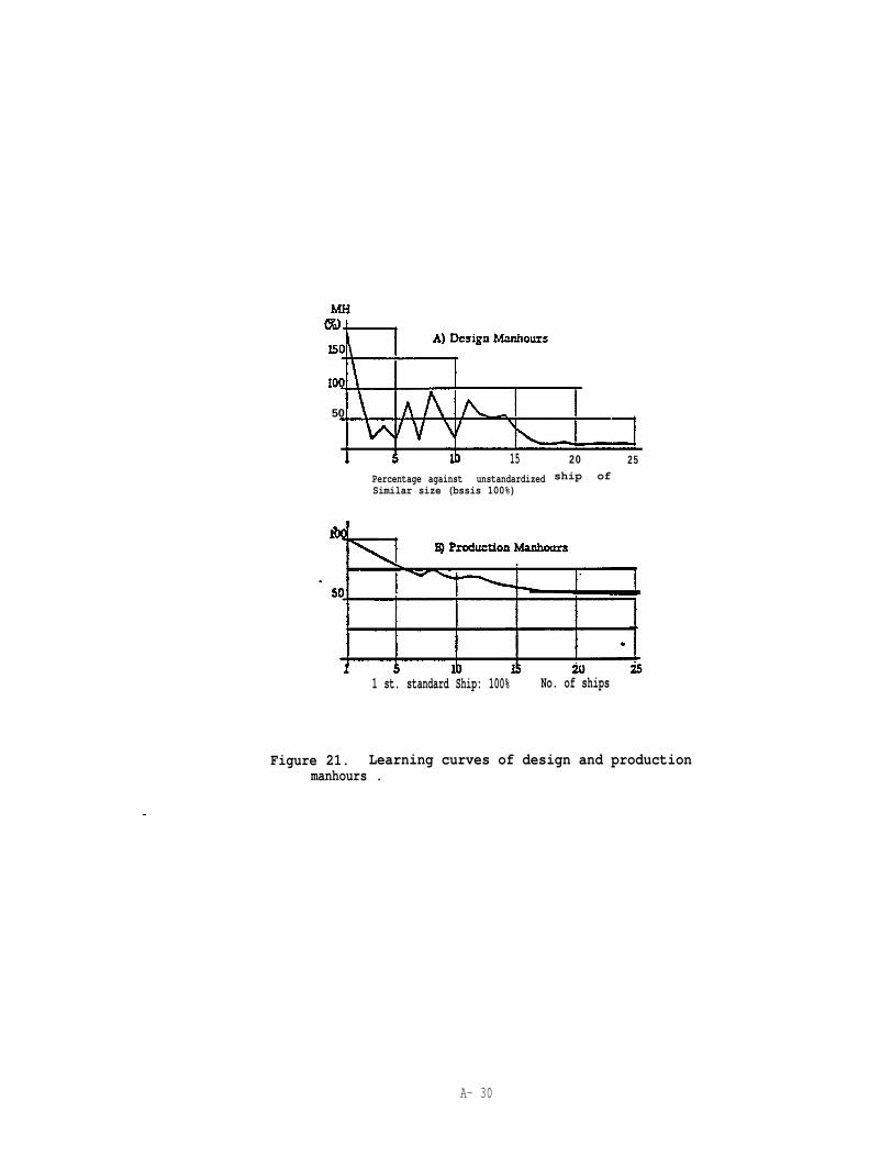
(1) Reduction of Manhours. Figure 21 shows the design and production
manhours of one of the standard F-series. Figure 21 (A) shows the design
manhour curve compared with an unstandardized ship. It may be surprising
that the design effort of the first ship required far more manhours than the
unstandardized ship, but this reflects the elaborate initial planning required
to implement the use of modules in connection with the production sequences,
and to facilitate the exercising of various options without interfering with
the base design. Figure 21 (B) shows the 1earning curve of the total Produc--
tion manhours. The manhours dropped steeply to about 80% by the 5th ship
and stabilized at about 55% by the 25th ship.
(2) Reduction in construction period. Compared with a similar unstan-
dardized Ship the construction period could be reduced by almost one-half-
A-29
50
15 20 25
Percentage against unstandardized ship ofSimilar size (bssis 100%)
1 st. standard Ship: 100% No. of ships
Figure 21. Learning curves of design and productionmanhours .
A- 30

(3) Higner quality and reliability of products. Standards and modules
are all based on long and proven experience in actual operation. Therefore,
they assume high quality and reliability. also, by standardization, equal
of the designer’s
(4) Establishment of an integrated design-to-production computer system.
It is true that these advantages are most fully enjoyed in series-built
standard designs or vessels of conventional types. Since the standards and
modules are confined to systems or items that are most commonly used, there
is difficulty in applying them in very special designs, such as systems
required for liquified gas carriers, specialized chemical carriers, or other
sophisticated ships, since these requirements will occur very seldan. But
even then, systems having conventional
standardized and modularized equipment
of design and production manhours.
A-31
features can still incorporate
and, thus, contribute to reduction

APPENDIX B
F - SHIPBUILDING
F - SHIPBUILDING
General
Glossary of Terms for Shipbuilding (Machinery
Glossary of Terms for Shipbuilding (MachineryMachinery and Boilers)
Glossary of Terms for Shipbuilding (MachineryMachinery and Equipments)
Glossary of Terms for Shipbuilding (Machinery
Glossary of Terms for Shipbuilding (Machinery
Glossary of Terms for Shipbuilding (MachineryPractice, Miscellaneous)
Part: General)
Part-Propulsion
Part-Auxiliary
Part-Instrumentation)
Part-Fittings)
Part: Testing, Working
Glossary of Terms for Shipbuilding (Electric Part)
Small Ships’ Schemes of Heat or Sweat Insulation for Pipes
Terminology and Definition of Output of Propulsion Machinery Installedin Ships
Fittings of the Machinery of Ships to be Supplied by Manufacturers
Terminology of Pressure used in Ships
Sea Water Temperature for Designing Marine Heat Exchangers
Coiled Springs for Marine Machinery
Equipment and Adjusting Pressure of Escape Valves for ShipMachinery
Application Standard for Use of Copper Pipes in Ships
Test Code of Propelling Machinery at Sea Trials
Shop Test Code for Marine AC Electric Overhead Travelling Cranesin Engine Room
Standard of Machine Tools Facility in Ships
Size of Spare Part Boxes for Marine Use
Small Ships’ Supply Standard for Hull INventory Articles
Hull Parts
Small Ships’ Rudder Carriers
Bollards
Cast Iron Dog Type Chain Cable Compressors
Cast Iron Deck End Rollers
Steel Plate Deck End Rollers
B-1

Hull Parts (Continued)
Closed Chocks
Open Chocks
Mooring Pipes
Spindle Type Hand Steering Gears
Ships’ Hand Steering Wheels
Chain Type Hand Steering Gears
Leading Blocks for Chain Type Hand Steering Gear
Fair-leads
Cast Steel Dog Type Chain Stoppers
Cast Steel Tongue Type Chain Cable Stoppers for Grade 2 ChainCable
Panama Chocks
Simple Type Bollards
Small Size Cast Iron Deck End Rollers
Small Size Steel Plate Deck End Rollers
Small Size Fairleads
Ships’ Horizontal Rollers
Ships’ Small Size Cast Steel Cable Compressors (Dog Type)
Ships’ Small Size Stand Rollers
Cable Clenches
Fairleaders with Horizontal Rollers
Roller Tongue Type Chain Cable Stoppers for Grade 2 Chain Cable
Roller Dog Type Chain Cable Stoppers for Grade 2 Chain Cable
Double Type Cross Bitts for Tug Boats
Turnbuckles for Lumber Lashing
Chains
Ships’
Ships’
Ships’
Ships’
Ships’
Ships’
Ships’
for Lumber Lashing
Davits for General Use
Cranes for General Use
Cargo Hooks
Chains for General Use
Derrick Booms
Derrick Topping Brackets
Derrick Gooseneck Brackets
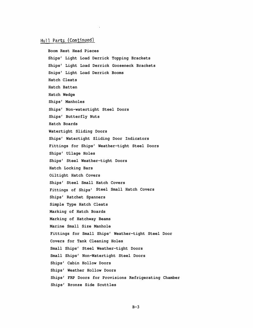
Boom Rest Head Pieces
Ships’ Light Load Derrick Topping Brackets
Ships’ Light Load Derrick Gooseneck Brackets
Snips’ Light Load Derrick Booms
Hatch Cleats
Hatch Batten
Hatch Wedge
Ships’ Manholes
Ships’ Non-watertight Steel Doors
Ships’ Butterfly Nuts
Hatch Boards
Watertight Sliding Doors
Ships’ Watertight Sliding Door Indicators
Fittings for Ships’ Weather-tight Steel Doors
Ships’ Ullage Holes
Ships’ Steel Weather-tight Doors
Hatch Locking Bars
Oiltight Hatch Covers
Ships’ Steel Small Hatch Covers
Fittings of Ships’ Steel Small Hatch Covers
Ships’ Ratchet Spanners
Simple Type Hatch Cleats
Marking of Hatch Boards
Marking of Hatchway Beams
Marine Small Size Manhole
Fittings for Small Ships’ Weather-tight Steel Door
Covers for Tank Cleaning Holes
Small Ships’ Steel Weather-tight Doors
Small Ships’ Non-Watertight Steel Doors
Ships’ Cabin Hollow Doors
Ships’ Weather Hollow Doors
Ships’ FRP Doors for Provisions Refrigerating Chamber
Ships’ Bronze Side Scuttles
B-3
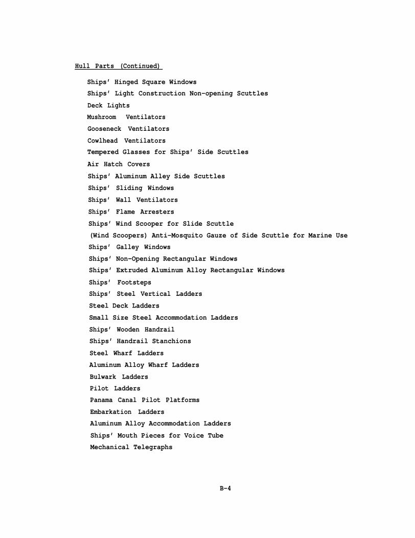
Hull Parts (Continued)
Ships’ Hinged Square WindowsShips’ Light Construction Non-opening Scuttles
Deck Lights
Mushroom Ventilators
Gooseneck Ventilators
Cowlhead VentilatorsTempered Glasses for Ships’ Side Scuttles
Air Hatch Covers
Ships’ Aluminum Alley Side Scuttles
Ships’ Sliding Windows
Ships’ Wall Ventilators
Ships’ Flame Arresters
Ships’ Wind Scooper for Slide Scuttle
(Wind Scoopers) Anti-Mosquito Gauze of Side Scuttle for Marine Use
Ships’ Galley Windows
Ships’ Non-Opening Rectangular WindowsShips’ Extruded Aluminum Alloy Rectangular Windows
Ships’ FootstepsShips’ Steel Vertical Ladders
Steel Deck Ladders
Small Size Steel Accommodation Ladders
Ships’ Wooden Handrail
Ships’ Handrail Stanchions
Steel Wharf Ladders
Aluminum Alloy Wharf Ladders
Bulwark Ladders
Pilot Ladders
Panama Canal Pilot Platforms
Embarkation Ladders
Aluminum Alloy Accommodation Ladders
Ships’ Mouth Pieces for Voice Tube
Mechanical Telegraphs
B-4

Hull Parts (Continued)
Fittings for Steam Whistle
Lifeboats
Radialships'
Ships'
Ships’
Ships’
Ships’
Hinged
Type Boat DavitCross Bitts
Punkah-Louvre
Rice Boilers
Steam Water Boilers
Oil Burning Cooking Ranges
Caps of Sounding Pipes
Deck Pieces for Sounding PipesPipe Head Caps
Pipe Head Spanners
Ships’ Bottom Plugs
Ships’ Drain Plugs
Deck and Bulkhead Pieces for Transmission Shaft
Ships’ 5 kgf/cm2 and 10 kgf/cm2 Deck and Bulkhead Pieces for PipeConnection
Universal Joints of Transmission Shafts in Cargo Oil Tanks
Goose Neck Air Pipe Heads (Ball Float Type)
Scupper Fittings for Ships’ Refrigerating Chambers
Gratings of Ships’ Scupper Pipes
Ships’ Cast Iron Pipe Sleeve Type Expansion Joints
Ships’ Cast Steel Pipe Sleeve Type Expansion Joints
Self-closing Parallel Cook Heads for Short Sounding Pipeself-closing Gate Valve Heads for Short Sounding pipe
Ships’ Oil Suction Bellmouths
Ships’ Steel Pipe Bands
Ships’ U-Bolts for Steel Pipe
Bonnet Type Air Pipe Heads
Ships’ Deck Stands for Controlling Valves
Remote Handling Fittings for Valves on Small Ships’ ForepeakBulkhead
Remote Handling Fittings for Valves in Small Ships’ Cargo Oil Tank
B-5

Hull Parts (Continued)
Ships’ Deck and Bulkhead Pieces for Small Size Copper Tubes
Ships’ Foot Valves
Eronze Vertical Storm Valves
Cast Steel Vertical Storm Valves
Bronze Screw-down Vertical Storm Valve
Cast Steel Screw-down Vertical Storm Valves
Ships’ Hand Piston Pumps
Hand Winches for Accommodation Ladders
Anchors
Cast Steel Anchor Chain Cables
Electrically Welded Anchor Chain CablesTools for Anchor Chain Cables
Buoy Shackles
Anchor Stoppers
Anchor Buoys
Anchor Stoppers (Small Size)
Rigging Screw
Chain Slings
Chain Stoppers
Small Size Chain Slings
Ships’ Eye Plates
Ships’ Ring Plates
Sunken Link Plates
Horn Cleats
Ships’ Wire Rope Stay Eye Plates
Ships’ Cargo Guy Cleats
Ships’ Small Size Snatch Blocks
Ships’ Sheaves
Ships’ Steel Guy Blocks with Swivels for Fibre RopeLifeboats’ Steel Blocks
Ships’ Steel Cargo Blocks
Ships’ Snatch Blocks
Ships’ External Bound Blocks
B 6

Hull Parts (Continued)
Ships’ Steel Blocks for Fibre Rope GuyShips’ Steel Blocks for Signal Flags
Ships' Internal-Bound Blocks
Ships’ Steel Cargo Lifting Blocks for Topping Units
Ships’ Cast Steel Cargo Blocks with Roller Bearings
Ships’ Steel Plate Cargo Lifting Blocks with Roller Bearings
Ship’s Wire Reels
Ships’ Steel Wire Sockets
Application Standard of Steel Wire Rope for Marine Use
Application Standard of Hemp Rope for Ship Use
Ship’s Wire Nippers for Topping Lifts
Ship’s Small Size Wire Reels
Application Standard of Steel Wire Rope for Small Ship
Application Standard of Hemp Rope for Small Ship
Fastening Method of Wire Ropes to Drum for Ship Use
Application Standard of Ships’ Canvas
Ships’ Hatch Beam Slings
Ships’ Small Size Wire Nippers for Topping Lift
Ships’ Small Size Steel Blocks
Ships’ Fire Axes
Jacobs’ Ladder
Ships’ Clinometers
Ships’ Bells
Ships’ Toggle Pins
Ships’ Chainlets
Ships’ Ring of Chainlet
Ships’ Eye Plates for Chainlet
Dredger’s Anchors
Dredger’s Sheaves for General Use
Dredger’s Discharge Pipes
Dredger’s Floaters
B-7

Engine Parts
Shop Test Code for Marine Steam Turbines for Propelling Use
Water Cooled Four Cycle Marine Diesel Engines for Propelling Use
Marine Hot-Bulb Engines for Propelling Use
Shop Test Code for Marine Internal Combustion Engines forPropelling Use
Water Cooled Spark Ignition Marine Engines for Propelling Use
Water Cooled Four Cycle Marine Diesel Engines for Electric Generator
Fuel Injector of Marine Small Diesel Engine
Fixing Parts of Ships’ Small Propellers
Morison Furnaces for Marine Use
Size of Dry Combustion Cylindrical
Fire Bar for Marine Use
Forged Steel 20 kg/cm2 Reflex TypeMarine Boilers
Forged Steel 20 kg/cm2 Reflex TypeMarine Boilers
Forged Steel 63 kg/cm2 Transparentfor Marine Boilers
Boilers for Marine Use
Water Gauges with Cocks for
Water Gauges with Valves for
Type Water Gauges with Valves
Shop Test Code for Marine Centrifugal Oil Purifiers
Ships’ Steam Cargo Winches
Marine DC Electric Cargo Winches
AC Electric Mooring Winches
Steam Mooring Winches
Hydraulic Mooring Winches
Steam Anchor Windlasses
DC Electric Anchor Windlasses
AC Electric Anchor Windlasses
Hydraulic Anchor Windlasses
Shop Test Code for Hydraulic Steering Gears for Ships
Shop Test Code for Oil Pressure Pumps of Hydraulic Steering Gearsfor Ships
Ship’s Small Size Fuel Oil Heaters
Tachometers for Marine Engine
Application Standard of Pressure Gauges on BoardStandard for Thermometers Arrangement in Ship’s Machinery Space
Identification of Piping Systems for Marine Use
B-8

Engine Parts (Continued)
Marine Turnbuckles with Eye Bolts
Pressure Gauge Boards for Marine Auxiliary Machines
Standard Velocity of F1OW in pipes of ship Machinery
Application Standard of Gaskets and Packings to Piping System forMarine Machinery
Marine Ventilation Dampers
Marine Can Water Filters
Distance Pieces for Ship’s Hull
Marine Duplex Oil Strainers
Marine Mud Boxes
Marine Rose Boxes of Steel Plate
Application for Wire Gauge of Oil Strainer for Marine Use
Marine
Marine
Marine
Marine
Marine
Marine
Marine
MarineMarine
Marine
Marine
Marine
Marine
Marine
Marine
Marine
Marine
Double
Marine
Marine
Duplex Oil Strainers (H Type)
Simplex Oil Strainers
Thermometer Pickets
5 kgf/cm2 Level Gauges with Valves
Oil Level Gauges with Self Closing Valves
16 kg/cm2 Water Gauges with Valve
Flat Glass Oil Level Gauges
Self Closing Valves for Oil Level GaugesFloat Level Gauges
Cylindrical Sight Glasses
Steel Plate Hoppers
Cast Iron 5 kg/cm2 Y Type Steam Strainers
Cast Iron 10 kg/cm2 Y Type Steam Strainers
Cast Steel 40 kg/cm2 Y Type Steam Strainers
Small Size Water Strainers
Small Size Duplex Oil Strainers
Steel Plate Simplex Oil Strainers
Bottom Tank Float Gauges for Coastal Ships
Tube Type Drain Silencers
Slit Type Drain Silencers
Starting Air Reservoirs Made of Steel Plate for Marine Use
Starting Air Reservoirs Made of Steel Tube for Marine Use
B-9
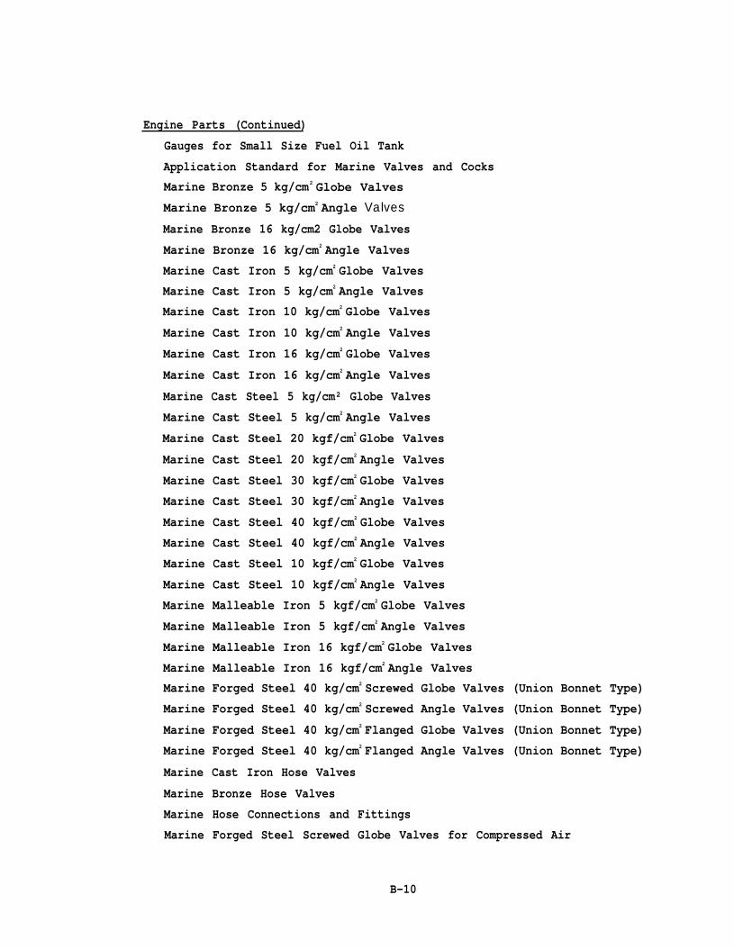
Engine Parts (Continued)
Gauges for Small Size Fuel Oil Tank
Application Standard for Marine Valves and CocksMarine Bronze 5 kg/cm2 Globe Valves
Marine Bronze 5 kg/cm2 Angle Valves
Marine Bronze 16 kg/cm2 Globe Valves
Marine Bronze 16 kg/cm2 Angle Valves
Marine Cast Iron 5 kg/cm2 Globe Valves
Marine Cast Iron 5 kg/cm2 Angle Valves
Marine Cast Iron 10 kg/cm2 Globe Valves
Marine Cast Iron 10 kg/cm2 Angle Valves
Marine Cast Iron 16 kg/cm2 Globe Valves
Marine Cast Iron 16 kg/cm2 Angle Valves
Marine Cast Steel 5 kg/cm² Globe Valves
Marine Cast Steel 5 kg/cm2 Angle Valves
Marine Cast Steel 20 kgf/cm2 Globe Valves
Marine Cast Steel 20 kgf/cm2 Angle Valves
Marine Cast Steel 30 kgf/cm2 Globe Valves
Marine Cast Steel 30 kgf/cm2 Angle Valves
Marine Cast Steel 40 kgf/cm2 Globe Valves
Marine Cast Steel 40 kgf/cm2 Angle Valves
Marine Cast Steel 10 kgf/cm2 Globe Valves
Marine Cast Steel 10 kgf/cm2 Angle Valves
Marine Malleable Iron 5 kgf/cm2 Globe Valves
Marine Malleable Iron 5 kgf/cm2 Angle Valves
Marine Malleable Iron 16 kgf/cm2 Globe Valves
Marine Malleable Iron 16 kgf/cm2 Angle ValvesMarine Forged Steel 40 kg/cm2 Screwed Globe Valves (Union Bonnet Type)
Marine Forged Steel 40 kg/cm2 Screwed Angle Valves (Union Bonnet Type)
Marine Forged Steel 40 kg/cm2 Flanged Globe Valves (Union Bonnet Type)
Marine Forged Steel 40 kg/cm2 Flanged Angle Valves (Union Bonnet Type)
Marine Cast Iron Hose Valves
Marine Bronze Hose Valves
Marine Hose Connections and Fittings
Marine Forged Steel Screwed Globe Valves for Compressed Air
B-10

Engine Parts (Continued)
Marine
Marine
Marine
Marine
Marine
Marine
Marine
Marine
Marine
Marine
Marine
Marine
Marine
Marine
Marine
Marine
Marine
Marine
Marine
Marine
Marine
Marine
Marine
Marine
Marine
Marine
Marine
Marine
Marine
Marine
Marine
Marine
Marine
Forged Steel Screwed Angle Valves for Compressed Air
Forged Steel Flanged Globe Valves for Compressed Air
Forged Steel Flanged Angle Valves for Compressed Air
Cast Steel Globe Valves for Compressed Air
Forged Steel 100 kg/cm2 Pressure Gauge Globe Valves
Bronze 20 kgf/cm2 Pressure Gauge Cocks
Bronze 5 kg/cm2 Globe Valves (Union Bonnet Type)
Bronze 5 kg/cm2 Angle Valves (Union Bonnet Type)
Bronze 16 kg/cm2 Globe Valves (Union Bonnet Type)
Bronze 16 kg/cm² Angle Valves (Union Bonnet Type)
Hull Cast Steel Angle Valves
Bronze 5 kg/cm2 Screw-Down Check Globe Valves
Bronze 5 kg/cm² Screw-Down Check Angle Valves
Cast Iron 5 kg/cm2 Screw-Down Check Globe Valves
Cast Iron 5 kg/cm2 Screw-Down Check Angle Valves
Bronze 5 kg/cm2 Lift Check Valves
Cast Iron 5 kg/cm2 Lift Check Globe Valves
Cast Iron 5 kg/cm2 Lift Check Angle Valves
Hull Cast Steel Gate Valves
Cast Iron 5 kgf/cm² Gate Valves
Cast Iron 10 kgf/cm2 Gate Valves
Hull Cast Steel Globe Valves
Cast Steel 10 kgf/cm2 Gate Valves
Bronze 5 kg/cm2 Rising Stem Type Gate Valves
Bronze 10 kg/cm2 Rising Stem Type Gate Valves
Bronze 5 kgf/cm2 Swing Check Valves
Cast Iron 5 kg/cm2 Swing Check Valves
Cast Iron 10 kgf/cm2 Swing Check Valves
Cast Iron 10 kg/cm2 Screw-Down Check Globe Valves
Cast Iron 10 kg/cm2 Screw-Down Check Angle Valves
Cast Iron 16 kg/cm2 Screw-Down Check Globe Valves
Cast Iron 16 kg/cm2 Screw-Down Check Angle Valves
Brass 30 kg/cm2 Stop Valves with Bite Joint(s)
B-11

Engine Parts (Continued)
Marine
Marine
Marine
Marine
Marine
Marine
Marine
Marine
Marine
Marine
Marine
Marine
Marine
Marine
Bronze 5 kgf/cm2 Flanged Cocks
Bronze 16 kfg/cm2 Cocks
Bronze 2(! kgf/cm2 Globe Valves
Bronze 20 kgf/cm2 Angle Valves
Cocks with Locks
Cast Iron 3 kg/cm² Globe Valves
Cast iron 3 kg/cm² Angle Valves
Bronze 3 kg/cm2 Globe Valves
Bronze 3 kg/cm2 Angle Valves
Cast Iron 3 kg/cm2 Gate Valves
Cast Iron 5 kg/cm2 Suction Manifold Valves
Cast Iron 5 kg/cm2 Discharge Manifold Valves
Fuel Oil Tank Self-Closing Drain Valves
Fuel Oil Tank Emergency Shut-Off Valves
General Rules for Inspection of Marine Valves and Cocks
Marine Cast Steel 30 kg/cm² Flange Type Escape Valves
Marine Forged Steel 30 kg/cm2 Screw Escape Valves
Marine Bronze 5 kg/cm2 Screw-Down Check Globe Valves (Union Bonnet Type)
Marine Bronze 5 kg/cm2 Screw-Down Check Angle Valves (Union Bonnet Type)
Marine Bronze 16 kg/cm2 Screw-Down Check Globe Valves (Union Bonnet Type)
Marine Bronze 16 kg/cm2 Screw-Down Check Angle Valves (Union Bonnet Type)
Marine Bronze 5 kg/cm2 Lift Check Globe Valves (Union Bonnet Type)
Marine Bronze 5 kg/cm2 Lift Check Angle Valves (Union Bonnet Type)
Marine Bronze 16 kg/cm2 Lift Check Globe Valves (Union Bonnet Type)
Marine Bronze 16 kg/cm2 Lift Check Angle Valves (Union Bonnet Type)
Marine Forced Steel 20 kg/cm2 Screwed Globe Valves (Union Bonnet Type)
Marine Forged Steel 20 kg/cm2 Screwed Angle Valves (Union Bonnet Type)
Brass 30 kg/cm2 Unions with Bite Joint(s) for Marine Use
Marine 10 kg/cm2 Brazed Unions for Copper Tube
Marine 10 kg/cm² Screwed Unions for Copper Tube
Marine 10 kg/cm2 Welded Unions for Steel Pipe
Marine 10 kg/cm2 Screwed Unions for Steel Pipe
Marine 20 kg/cm2 Brazed Unions for Copper Pipe
Marine 20 kg/cm2 Screwed Unions for Copper Pipe
B-12
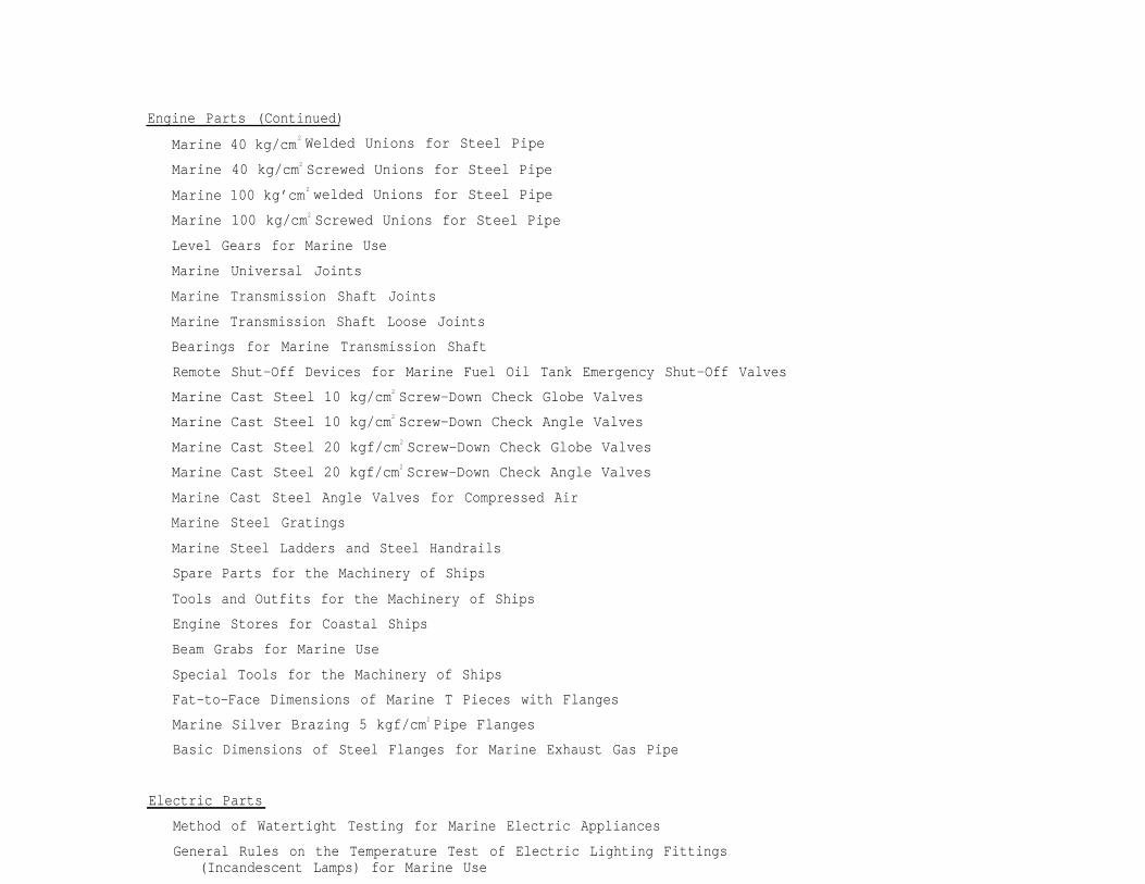
Engine Parts (Continued)
Marine 40 kg/cm 2 Welded Unions for Steel Pipe
Marine 40 kg/cm2 Screwed Unions for Steel Pipe
Marine 100 kg’cm 2 welded Unions for Steel Pipe
Marine 100 kg/cm2 Screwed Unions for Steel Pipe
Level Gears for Marine Use
Marine Universal Joints
Marine Transmission Shaft Joints
Marine Transmission Shaft Loose Joints
Bearings for Marine Transmission Shaft
Remote Shut-Off Devices for Marine Fuel Oil Tank Emergency Shut-Off Valves
Marine Cast Steel 10 kg/cm2 Screw-Down Check Globe Valves
Marine Cast Steel 10 kg/cm2 Screw-Down Check Angle Valves
Marine Cast Steel 20 kgf/cm2 Screw-Down Check Globe Valves
Marine Cast Steel 20 kgf/cm2 Screw-Down Check Angle Valves
Marine Cast Steel Angle Valves for Compressed Air
Marine Steel Gratings
Marine Steel Ladders and Steel Handrails
Spare Parts for the Machinery of Ships
Tools and Outfits for the Machinery of Ships
Engine Stores for Coastal Ships
Beam Grabs for Marine Use
Special Tools for the Machinery of Ships
Fat-to-Face Dimensions of Marine T Pieces with Flanges
Marine Silver Brazing 5 kgf/cm2 Pipe Flanges
Basic Dimensions of Steel Flanges for Marine Exhaust Gas Pipe
Electric Parts
Method of Watertight Testing for Marine Electric Appliances
General Rules on the Temperature Test of Electric Lighting Fittings(Incandescent Lamps) for Marine Use

Electric Parts (Continued)
Graphical Symbols for Electrical Apparatus (Power) for Marine EngineeringDrawings
Graphical Symbols for Electrical Apparatus (Lighting Fittings andAccessories) for Marine Engineering Drawings
Graphical Symbols for Electrical Apparatus (Communication) for MarineEngineering Drawings
Lead-Acid Marine Batteries
Lamp Holders for Marine Use
Glass Globes for Marine Electric Lights
Front Glasses for Marine Electric Lights
Glass Globes for Marine Indicator Lamps
Lenses for Marine Morse Signal Lamps
Marine Lamps
Recessed Type Ceiling Lights for Marine Use (Non-watertight Type)
Ceiling Lights for Marine Use (Non-watertight Type)
Cargo Lights
Boat Deck Lights
Pendant and Bracket Lights for Marine Use
Watertight Type Hand Lamps for Marine Use
Watertight Type Wall Lights for Marine Use
Floodlighting Projectors for Marine Use
Berth Lights for Marine Use
Chart Table Lights
Flameproof Ceiling Lights for Marine Use
Flameproof Bulkhead Lights for Marine Use
Explosion-Proof Flash Lights for Marine Use (Dry Battery Type)
Hand Lamps for Marine Use (Non-watertight Type)
Portable Lamps (Simple Type) for Marine Use
Pendant Lights (Simple Type) for Marine Use
Cargo Lights (Simple Type)
Ballast for Fluorescent Lamp for Marine Use
Fluorescent Table Lamps for Marine Use
Fluorescent Wall Lights for Marine Use (Non-watertight Type)
Fluorescent Ceiling Lights for Marine Use (Non-watertight Type)
Fluorescent Ceiling Lights for Marine Use (Watertight Type)
B-14
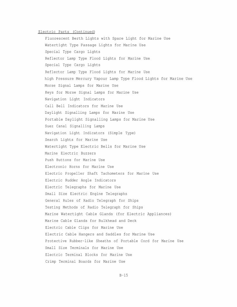
Electric Parts (Continued)
Fluorescent Berth Lights with Spare Light for Marine Use
Watertight Type Passage Lights for Marine Use
Special Type Cargo Lights
Reflector Lamp Type Flood Lights for Marine Use
Special Type Cargo Lights
Reflector Lamp Type Flood Lights for Marine Use
high Pressure Mercury Vapour Lamp Type Flood Lights for Marine Use
Morse Signal Lamps for Marine Use
Keys for Morse Signal Lamps for Marine Use
Navigation Light Indicators
Call Bell Indicators for Marine Use
Daylight Signalling Lamps for Marine Use
Portable Daylight Signalling Lamps for Marine Use
Suez Canal Signalling Lamps
Navigation Light Indicators (Simple Type)
Search Lights for Marine Use
Watertight Type Electric Bells for Marine Use
Marine Electric Buzzers
Push Buttons for Marine Use
Electronic Horns for Marine Use
Electric Propeller Shaft Tachometers for Marine Use
Electric Rudder Angle Indicators
Electric Telegraphs for Marine Use
Small Size Electric Engine Telegraphs
General Rules of Radio Telegraph for Ships
Testing Methods of Radio Telegraph for Ships
Marine Watertight Cable Glands (for Electric Appliances)
Marine Cable Glands for Bulkhead and Deck
Electric Cable Clips for Marine Use
Electric Cable Hangers and Saddles for Marine Use
Protective Rubber-like Sheaths of Portable Cord for Marine Use
Small Size Terminals for Marine Use
Electric Terminal Blocks for Marine Use
Crimp Terminal Boards for Marine Use
B-15

Electric Parts (Continued)
Watertight Type Joint Boxes for Marine Use
Joint Boxes for Marine Use (Non-watertight Type)
Distribution Boards (Fuse Type) for Marine Use
Section Boards (Fuse Type) for Marine Use
Shore Connection Boxes for Marine Use
Simple Type Distribution Boards for Marine Use
Simple Type Section Boards for Marine Use
Distribution Boards with Circuit Breakers for Marine Use
Section Boards with Circuit Breakers for Marine Use
Shore Connection Boxes (Small Type) for Marine Use
Non Watertight Type Plugs for Maine Use
Watertight Type Plugs for Marine Use
Watertight Type Receptacles for Marine Use
Non-Watertight Type Receptacles for Marine Use
Non-Watertight Type Snap Switches for Marine Use
Watertight Type Small Switches for Marine Use
Small Toggle Switches for Marine Use
Unit Switches for Marine Use
Rotary Switches for Marine Use
Control Switches for Marine Flameproof Light
Dimmers for Marine Lamps
Dimmers for Marine Instrument Illumination
Magnetic Compasses for Marine Use
B-16

APPENDIX C
MATERIAL STANDARDS
IS-SO Common Part (A, B and C Type Code)IS-SO Hull Part (Type-D Code)IS-SO Machinery Part (Type-D Code)IS-SO Electrical Part (Type-D Code)
ENGINEERING STANDARDS
IS-SOT Application of Standard of Materials (in directcorrespondence to IS-SO Material StandardsNumbering system)
IS-SOT - A Design Standard (General Facility and Work Plan)
IS-SOT - B Work Standard (Production Engineering Standards)

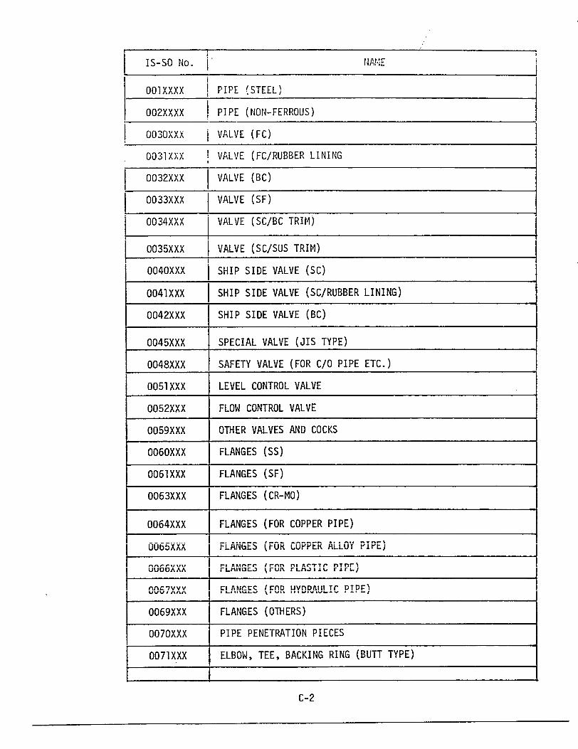
LIST OF IS-SO
COMMON PART
(A, B AND C - TYPE CODE)
C-1


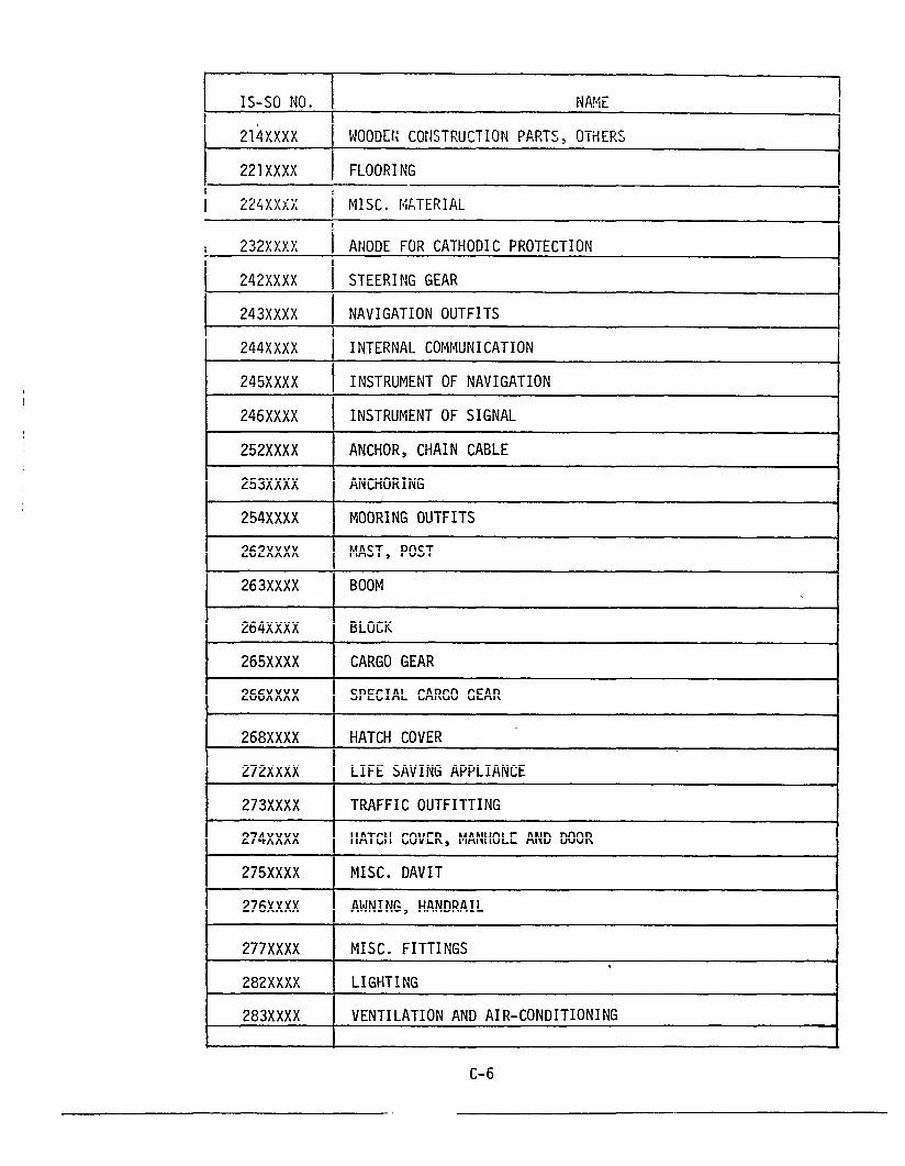
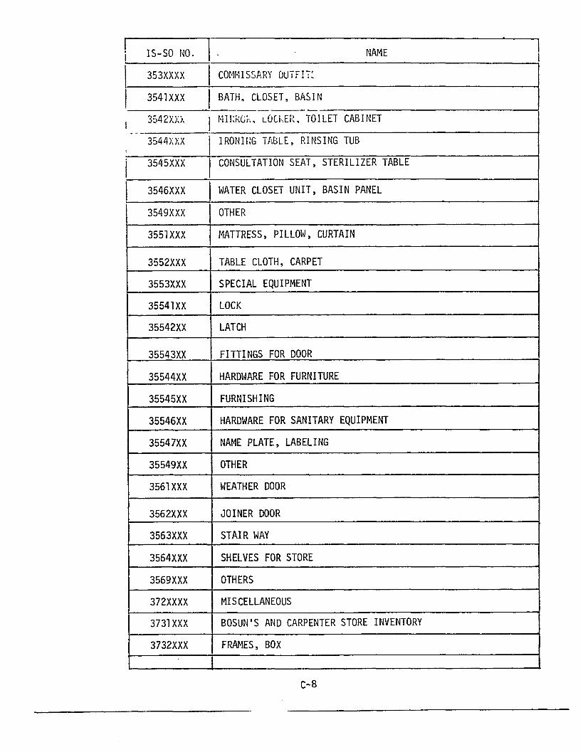
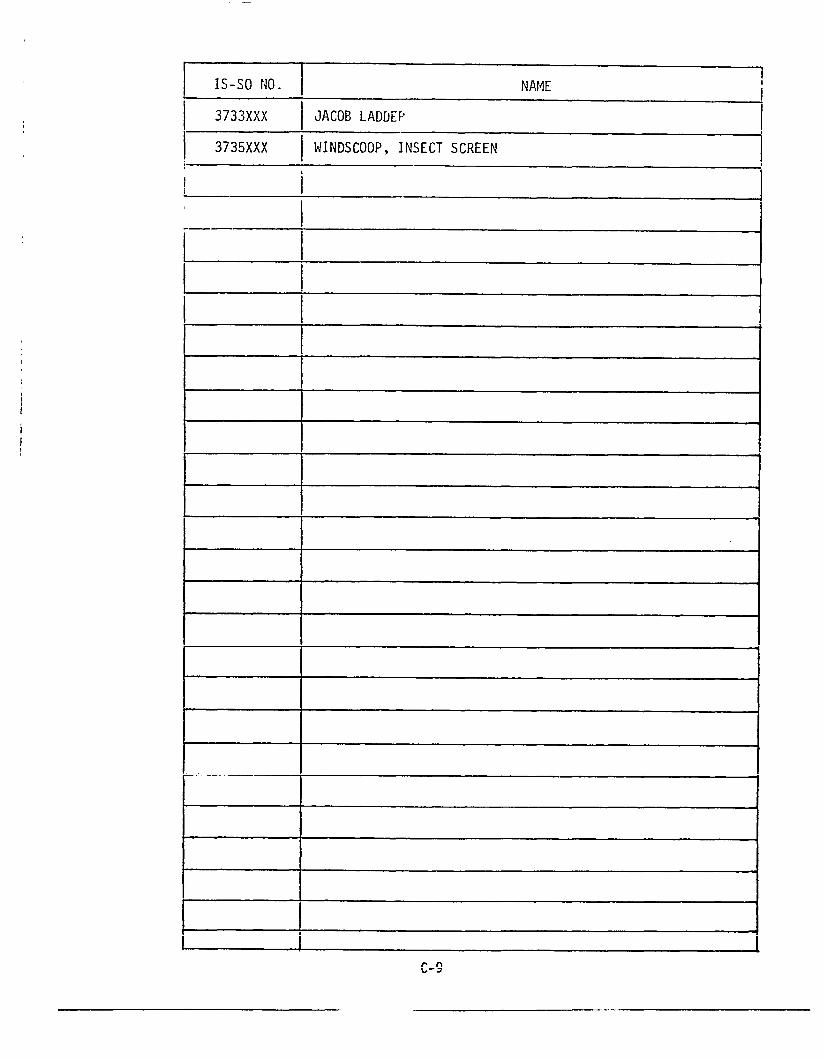
LIST OF IS-SO
HULL PART
(TYPE - D CODE)
c-5


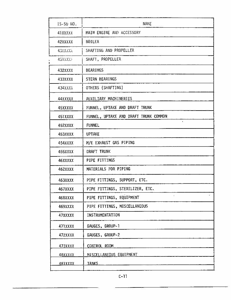
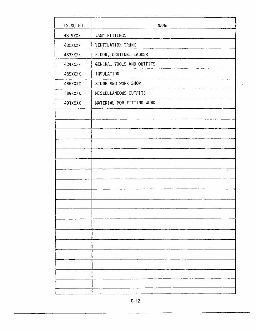
LIST OF IS-SO
MACHINERY PART
(TYPE - D CODE)
C-10

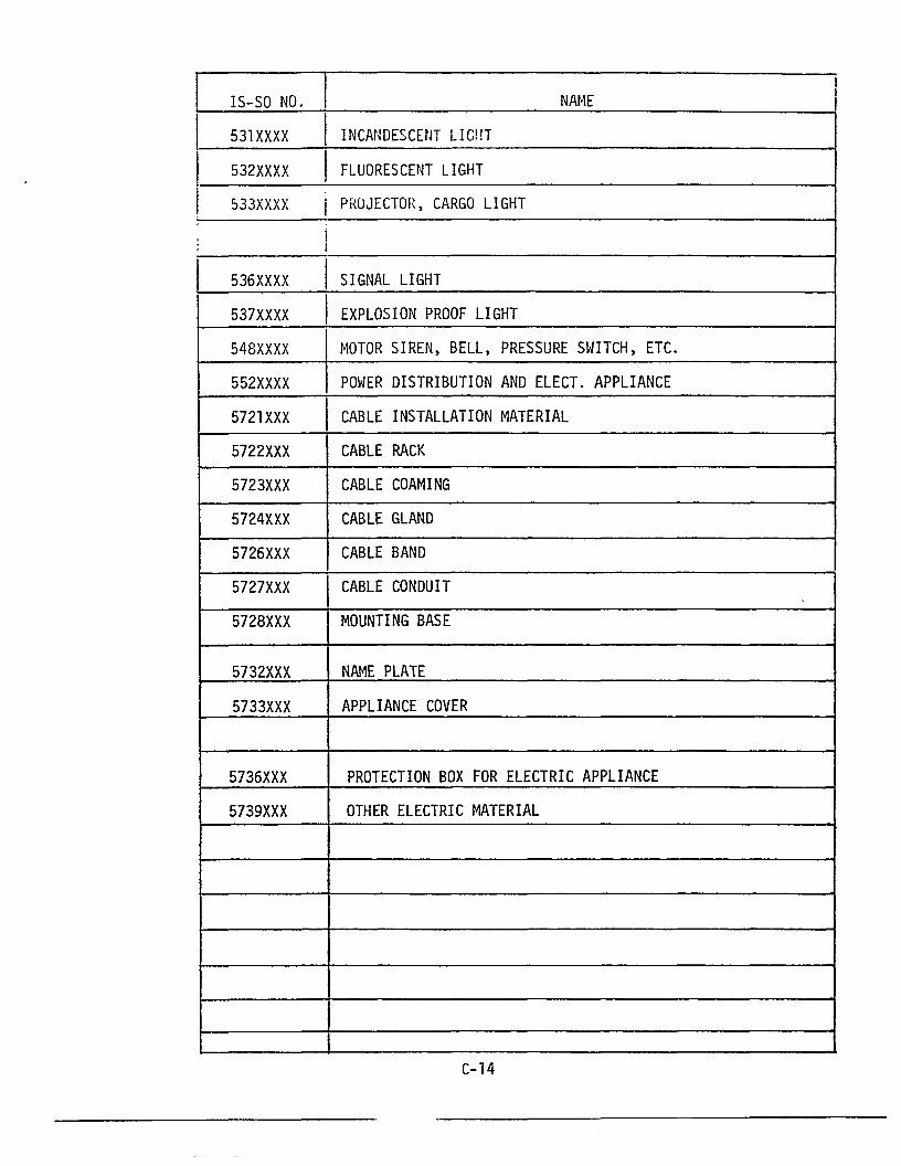
LIST OF IS-SO
ELECTRICAL PART
(TYPE - D CODE)
C-13

LIST OF IS-SOT
APPLICATION STANDARD
OF
MATERIALS
C-15


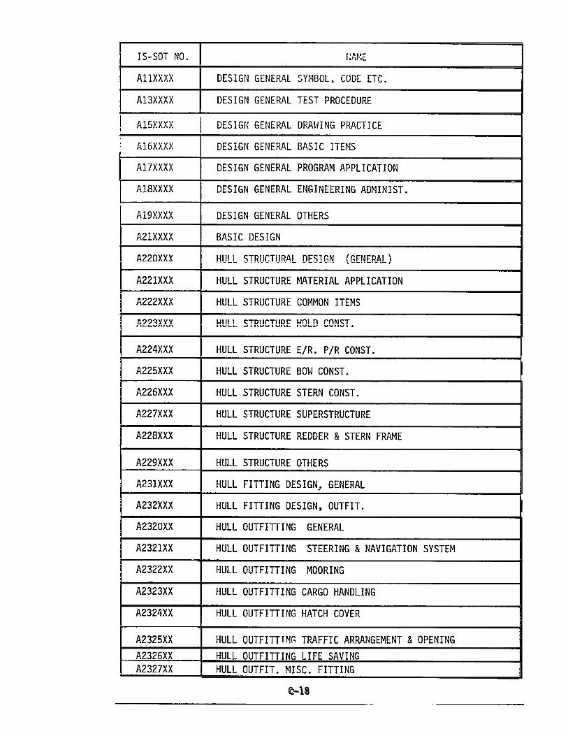
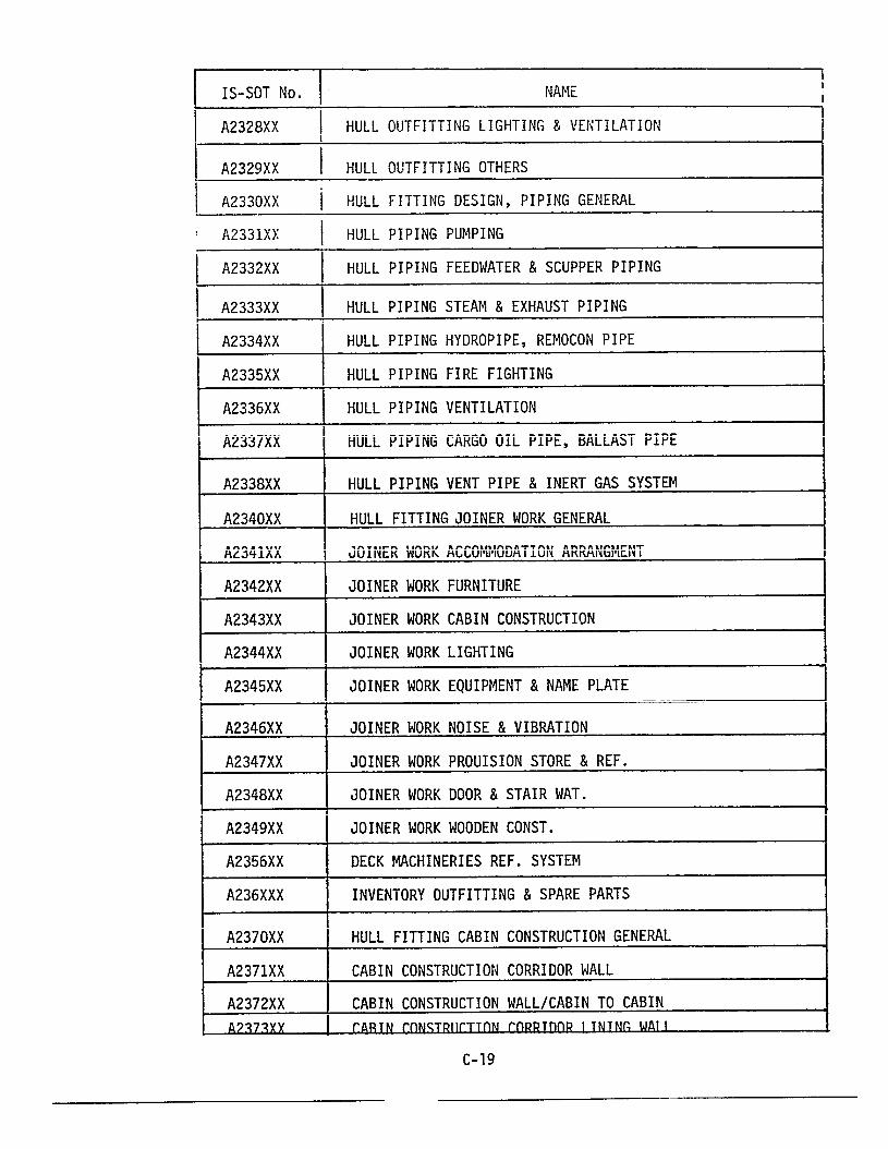
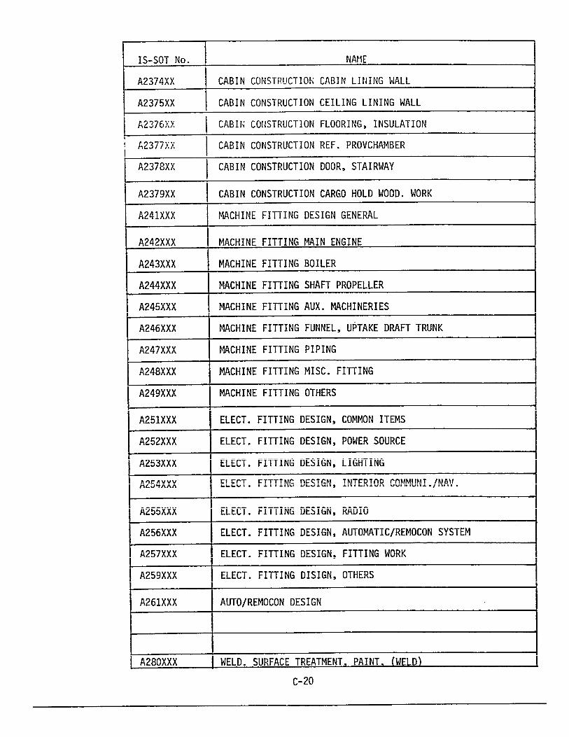
LIST OF IS-SOT-A
DESIGN STANDARD
GENERAL FACILITY AND WORK PLAN
C-17
I
I1I
I
I
I
I
C-18


APPENDIX D
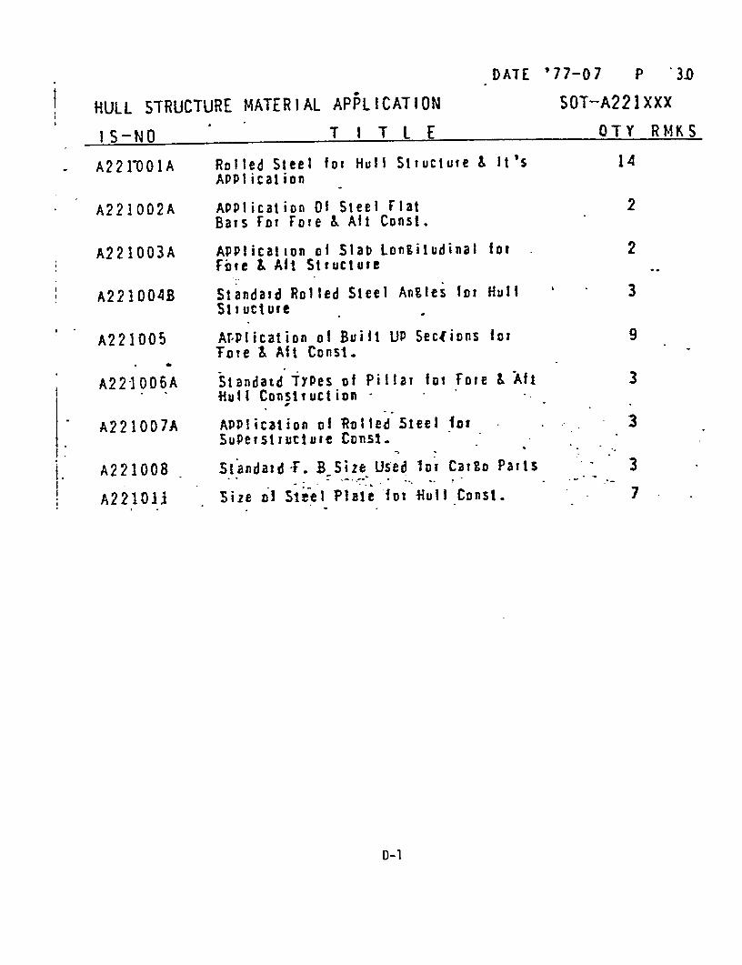
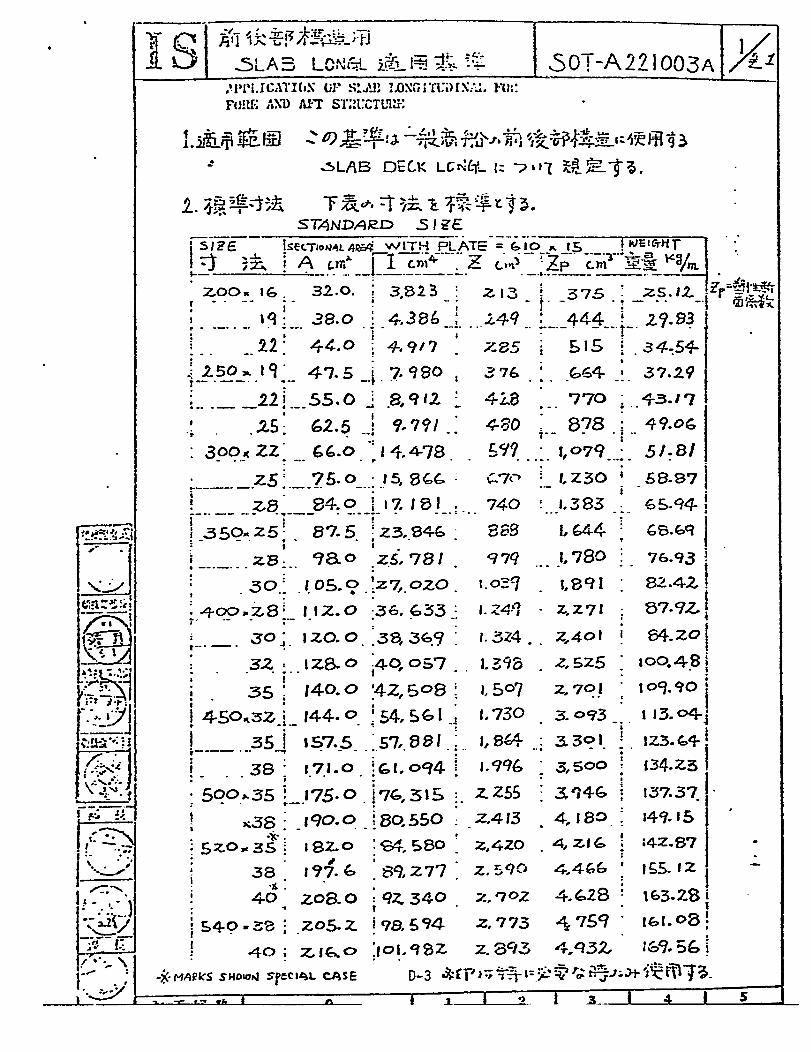
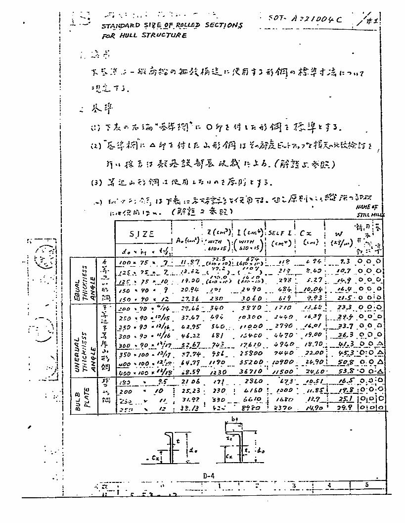
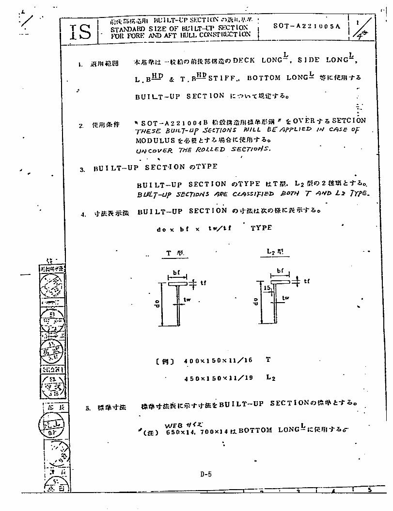
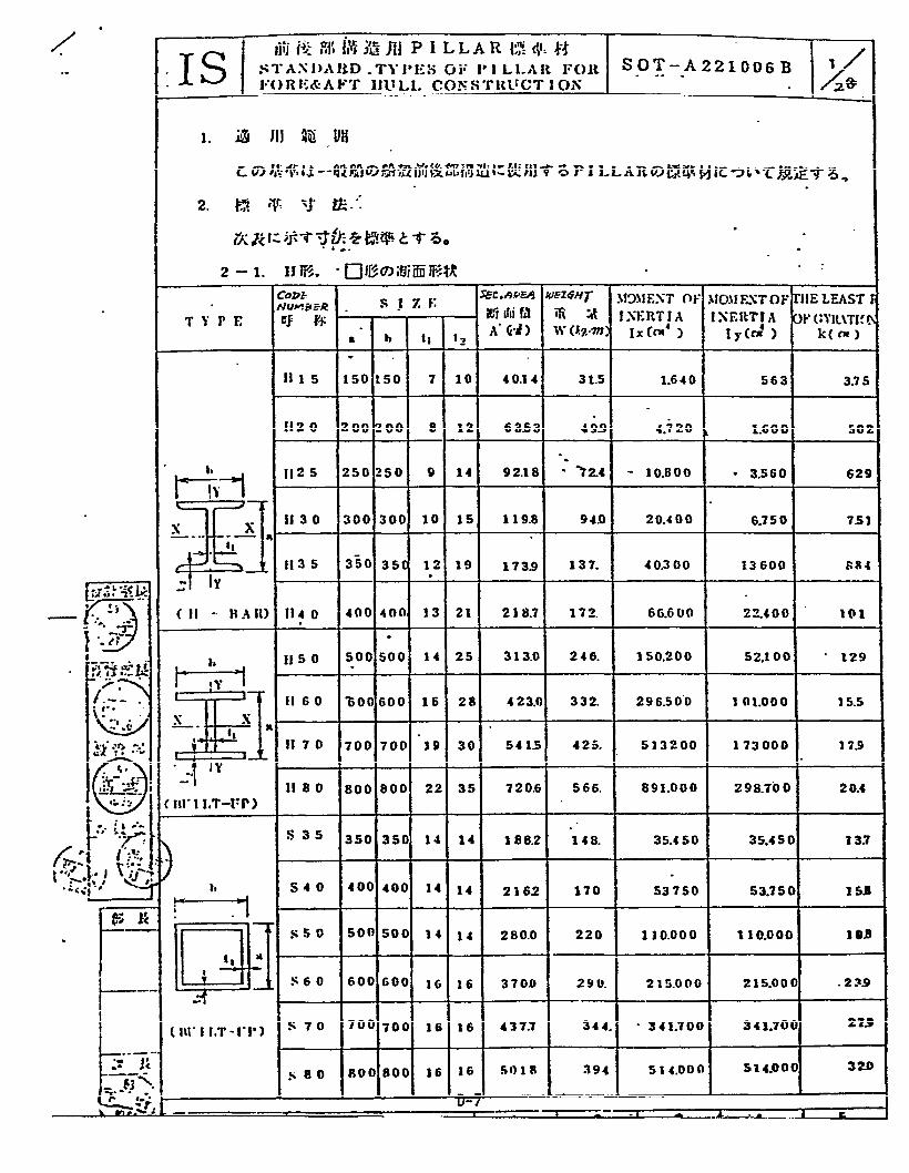
EXAMPLES OF IHI STANDARDS - SOT A221XXX
HULL STRUCTURE MATERIAL APPLICATION
NOTE: The standards contained in this sectionare included for instructional purposesonly. Some are more recent versions ofthe ones listed on the following page,which is from the detailed index. Noattempt, however, has been made toobtain the most recent revision of anystandard.


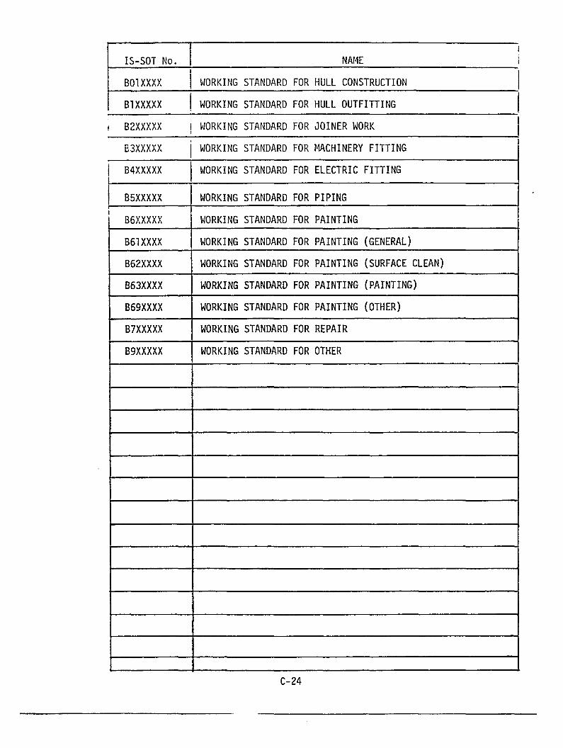
LIST OF IS-SOT-B
WORK STANDARD
C-23

APPENDIX E
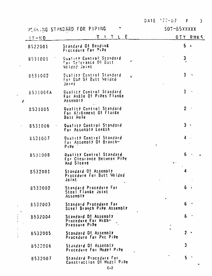
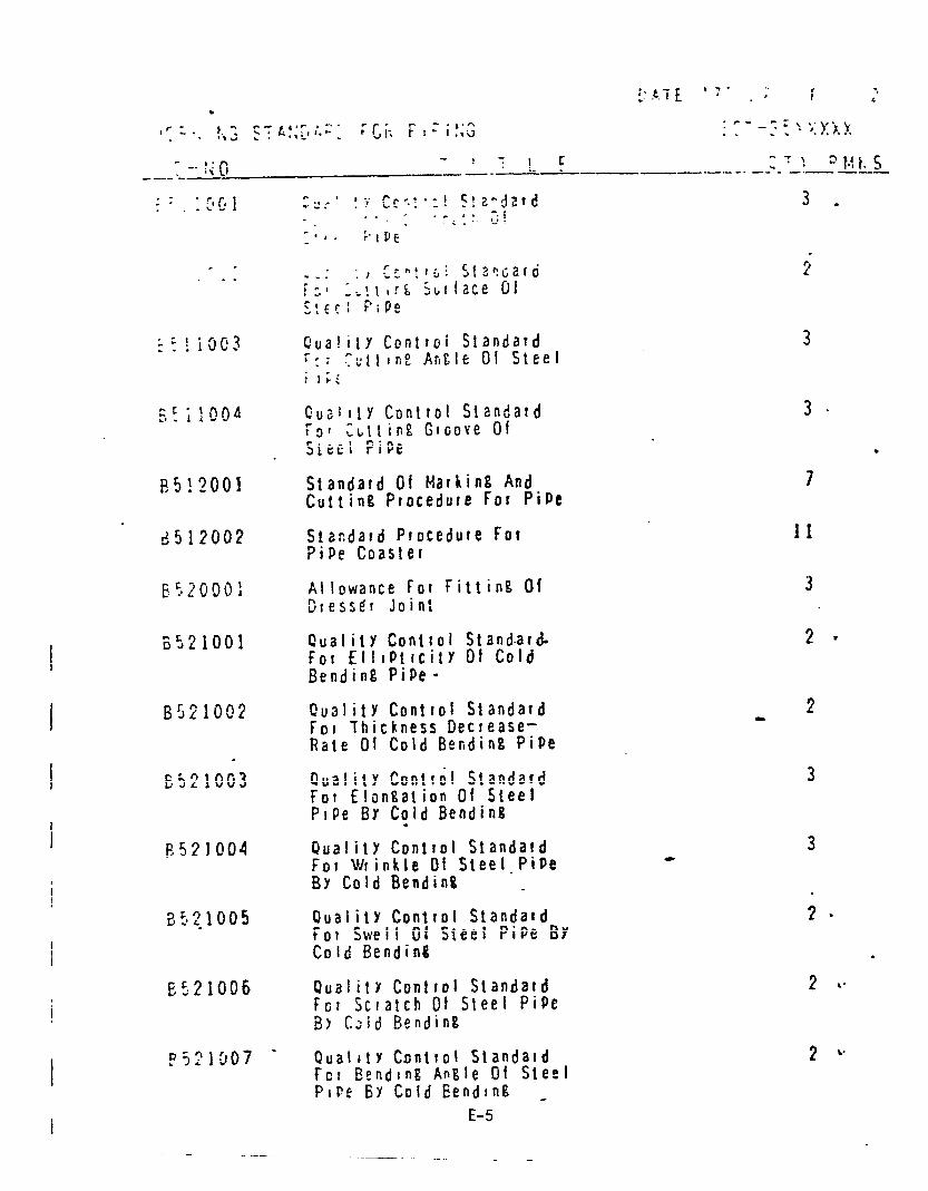
EXAMPLES OF IHI STANDARDS - SOT B5XXXXX
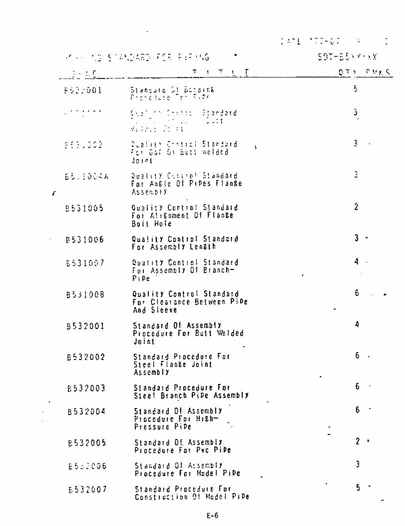
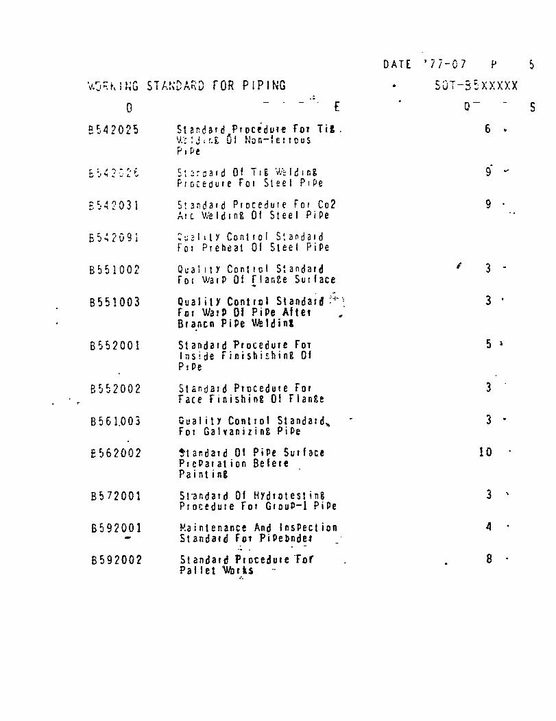
1. Extract from the detailed index forGroup B5XXXXX - Working Standard forPiping
2. Example standard SOT B552001 - StandardProcedure for Inside Finishing of Pipe
NOTE: The material in this index is presentedfor instructional purposes only.


2
2
3
7
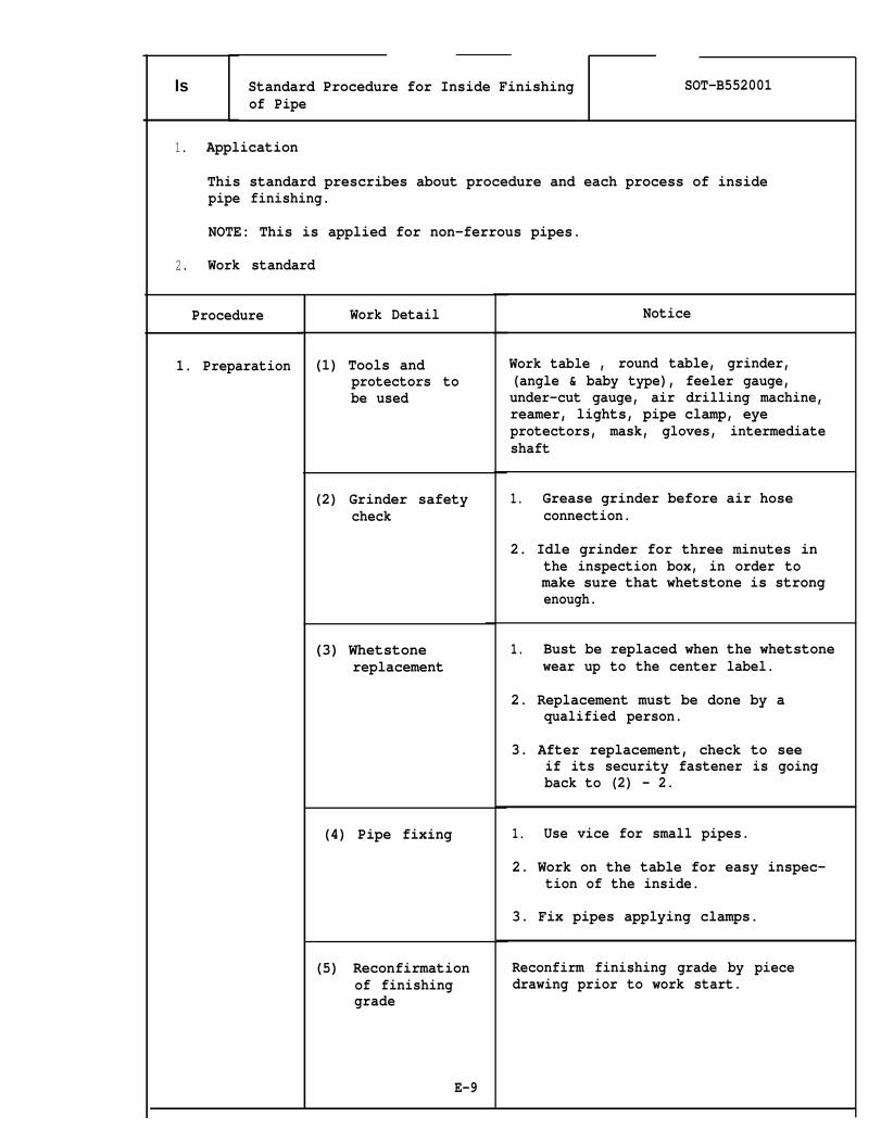
Is Standard Procedure for Inside Finishing SOT-B552001of Pipe
1. Application
This standard prescribes about procedure and each process of insidepipe finishing.
NOTE: This is applied for non-ferrous pipes.
2. Work standard
Procedure
1. Preparation
Work Detail
(1) Tools andprotectors tobe used
(2) Grinder safetycheck
(3) Whetstonereplacement
(4) Pipe fixing
(5) Reconfirmationof finishinggrade
E-9
Notice
Work table , round table, grinder,(angle & baby type), feeler gauge,under-cut gauge, air drilling machine,reamer, lights, pipe clamp, eyeprotectors, mask, gloves, intermediateshaft
1. Grease grinder before air hoseconnection.
2. Idle grinder for three minutes inthe inspection box, in order tomake sure that whetstone is strongenough.
1. Bust be replaced when the whetstonewear up to the center label.
2. Replacement must be done by aqualified person.
3. After replacement, check to seeif its security fastener is goingback to (2) - 2.
1. Use vice for small pipes.
2. Work on the table for easy inspec-tion of the inside.
3. Fix pipes applying clamps.
Reconfirm finishing grade by piecedrawing prior to work start.

IsI of Pipe I
2. Finishing (1) Toolselection
SOT-B552001
Nom.Dia.
E-10
Application of Tools & Drills
Tool
File
BabyGrinder
AirDrill-ing Machine
File
AirDrill-ingMachine
BabyGrinder
BabyGrinder
AngleGrinder(over
Drill
U1traHardened
Reamer
Reamer
Application
Flange insidebead & insidepipe
(includingsaddle part)
Inside Pipe(includinqsaddled part
Inside Pipe(includingsaddled part

I
(2) Finishingprocess
(3) Cleaning
E-11
Filing
1. Do not file without handle.
2. Clean the file before usage bywire brush.
3. Use rough surface file.
1. Work on the table.
2. Butt welded part.a. Grind lower halfb. Grind the rest after rolling 180°
3. Use intermediate shaft in grindingat deep inside pipe.
4. Start rotation after insert intopipe.
Do not approach with rotation.
1.
2.
3.
4.
ReamingFix a pipe by vice.
Approach reamer slowly to avoiddamage on reamer.
Check smoothness stopping occasion-ally.
Use round file for small pipes onwhich reaming is difficult.
After finishing process, do not forget toclean inside. Either blow air or standa pipe and give a few inpacts.

Is I Standard Procedure for Inside Finishing I SOT-B552001of Pipe
3. Confirmation (1) Final check
E-12
1. According to “Standard of insidepipe finishing)
SOT-B551OO1
Grade Standard Allowance
A -- h = 0~1.O
B - -
c I Not specified
2. Check using under-cut-gauge orfeller gauge case by case.
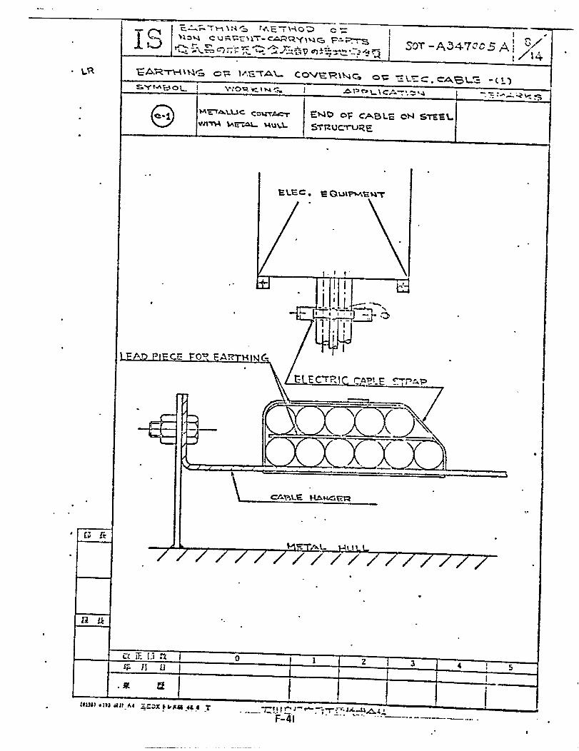
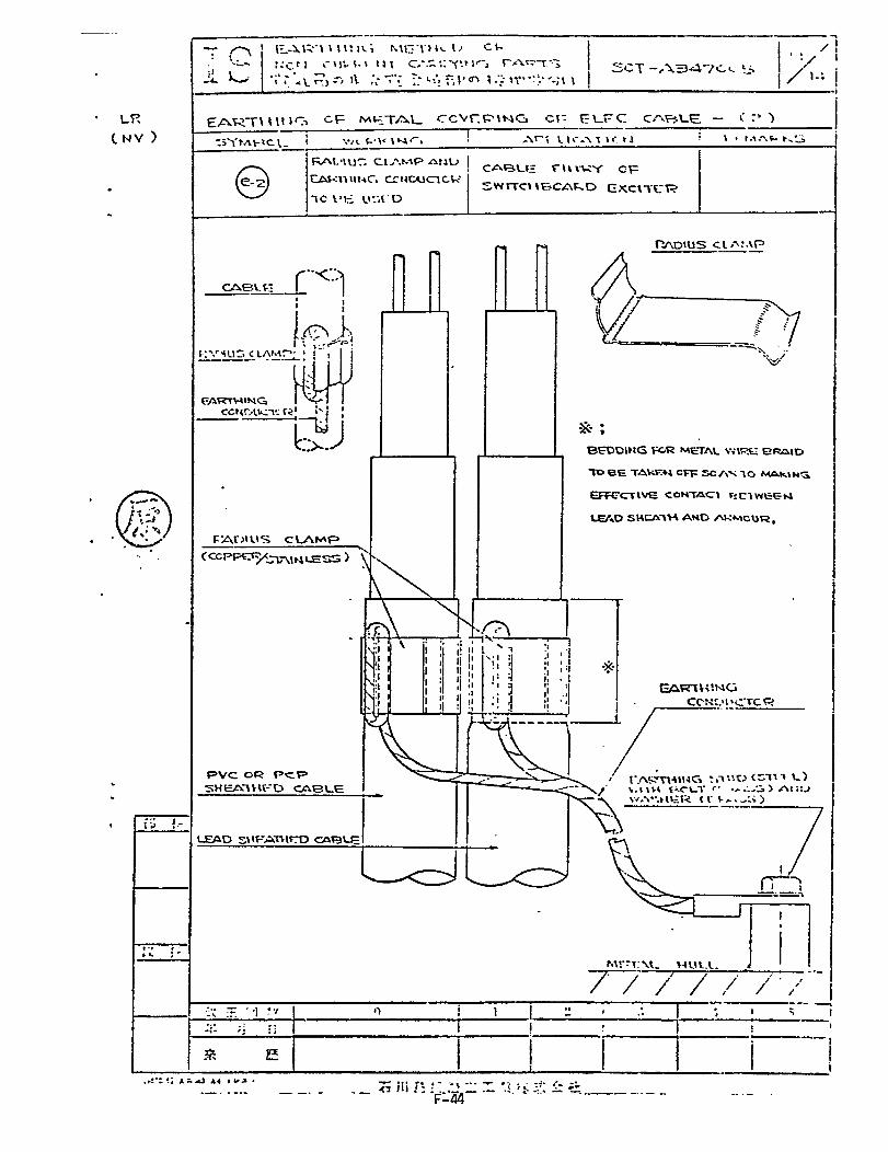
APPENDIX F
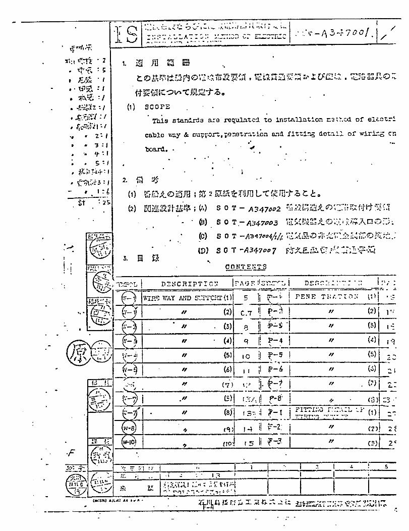
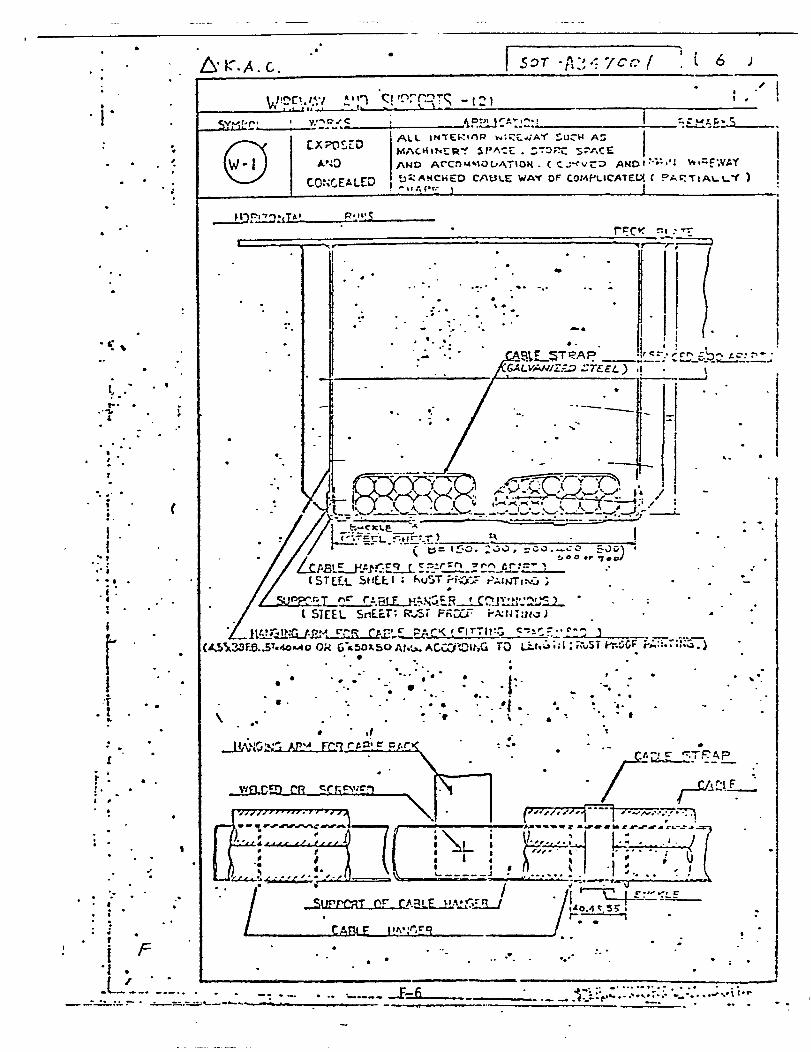
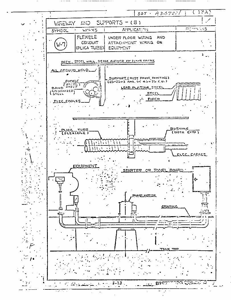
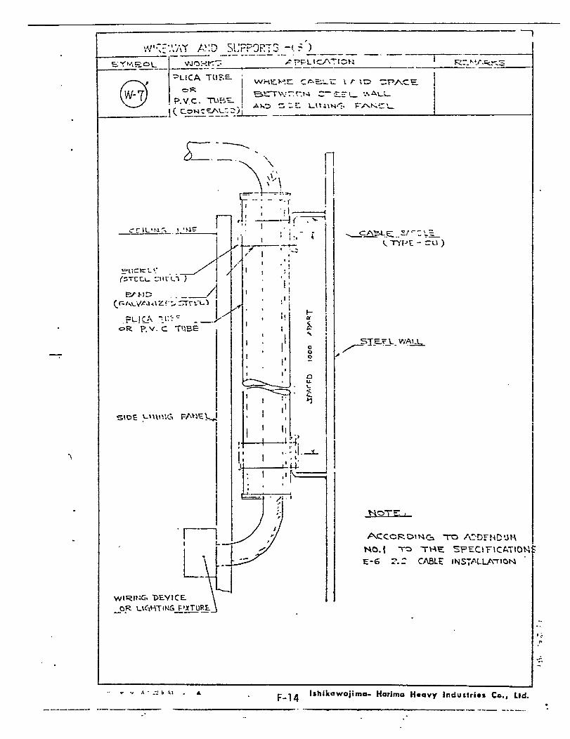
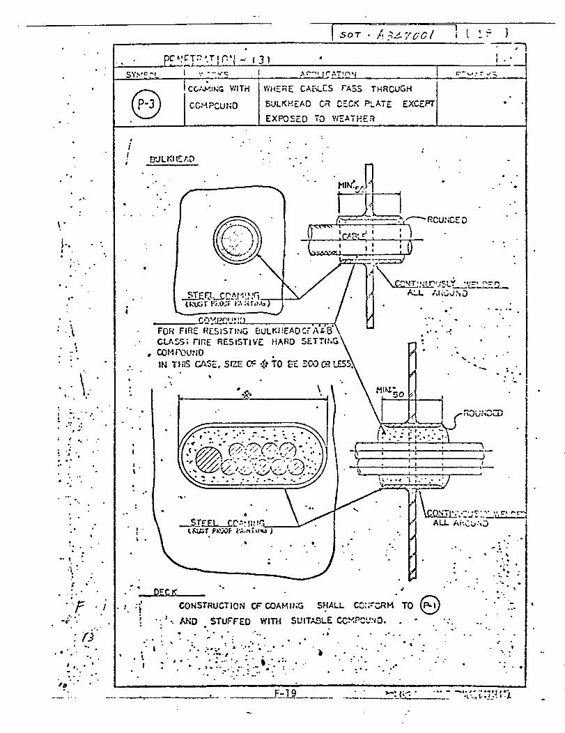
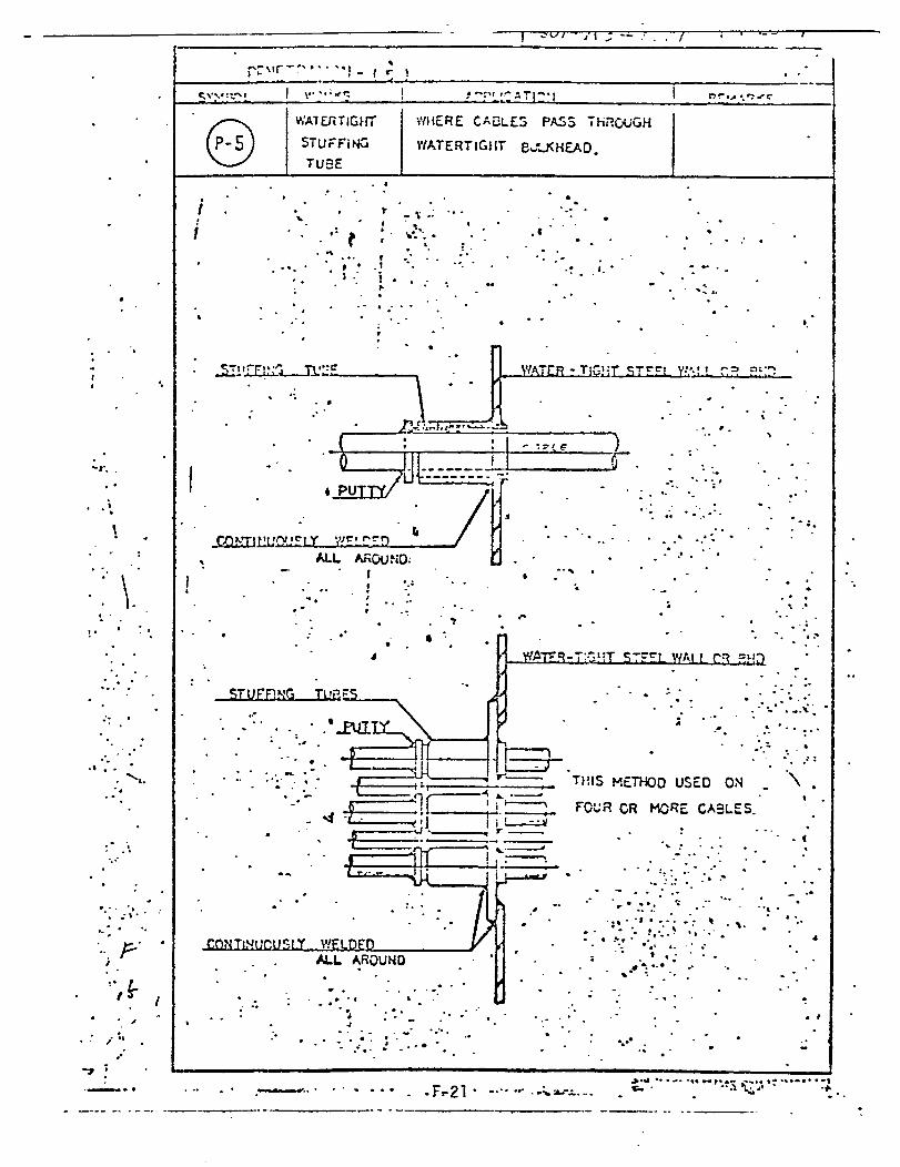
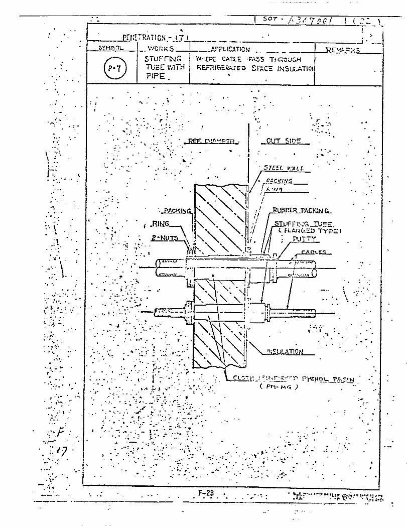
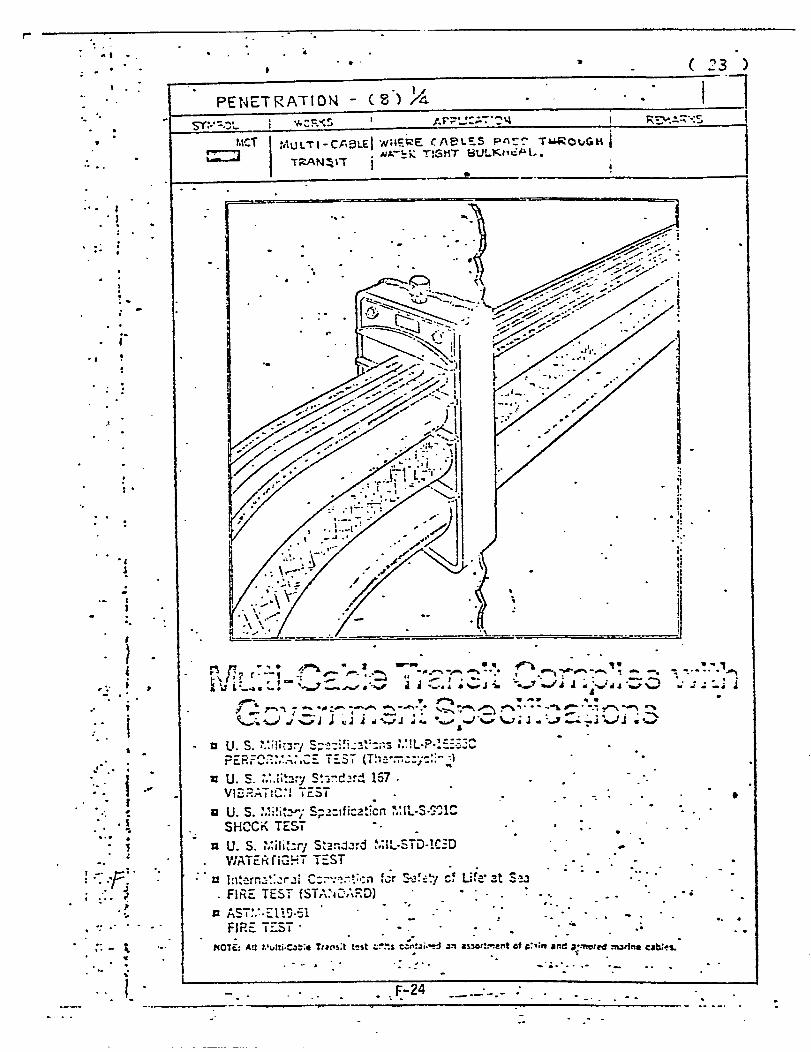
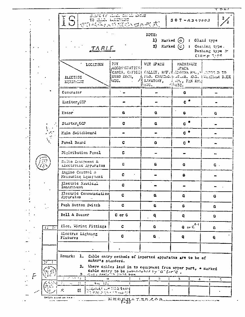
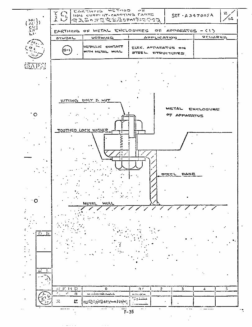
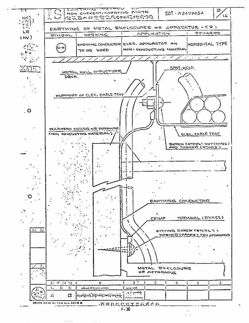
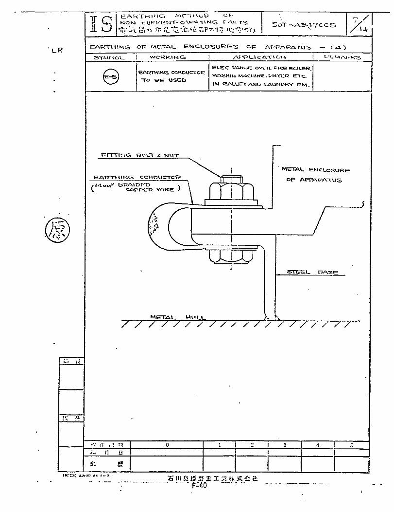
1.Group SOT A347XXX Electrical FittingProduction Design, Fitting Work
2. Design office drawing on “Practicefor Electrical Installation”


APPENDIX G
LIVINGSTON STANDARD OPERATING PROCEDURE
INITIATION, REVIEW,
AND
ISSUANCE OF LIVINGSTON STANDARDS
REF. POLICY - PROCEDURES CLASSIFICATION Inter-Directorate
I DIRECTORATES/DEPTS. AFFECTED All
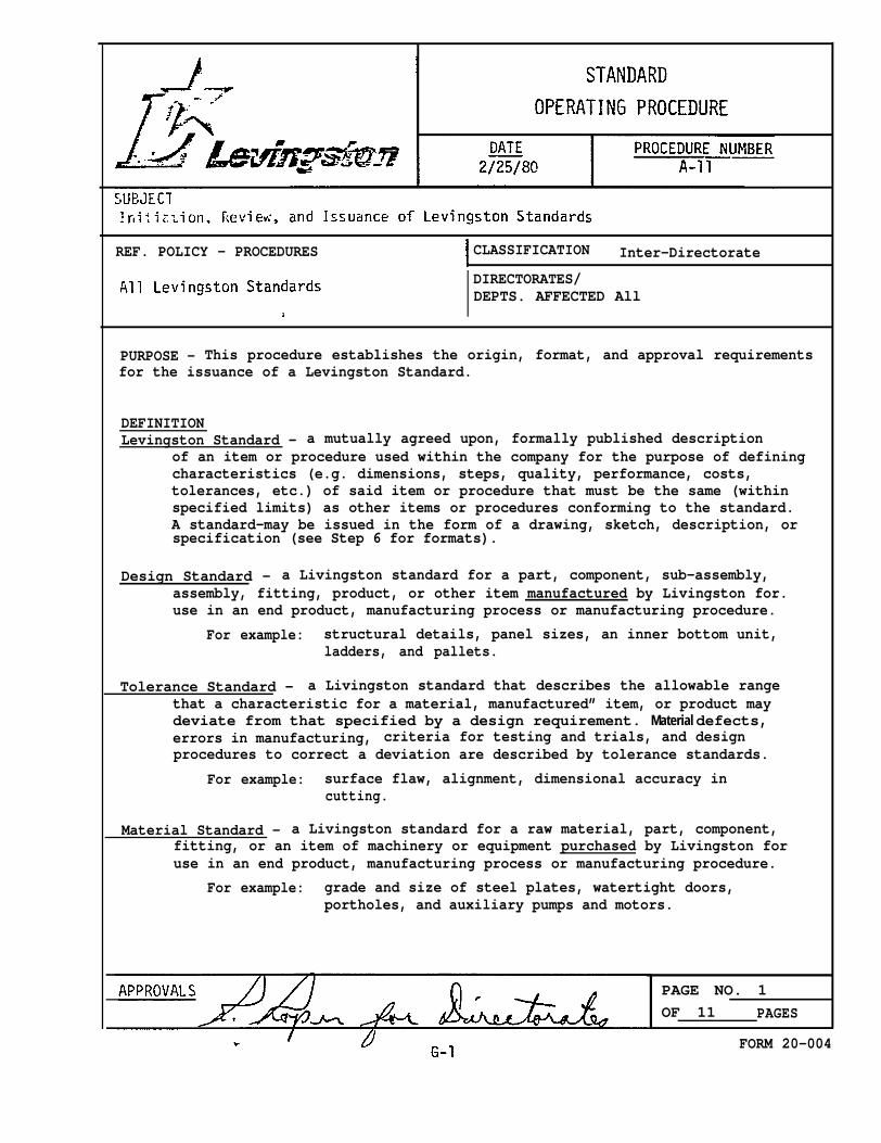
PURPOSE - This procedure establishes the origin, format, and approval requirementsfor the issuance of a Levingston Standard.
DEFINITIONLevingston Standard - a mutually agreed upon, formally published description
of an item or procedure used within the company for the purpose of definingcharacteristics (e.g. dimensions, steps, quality, performance, costs,tolerances, etc.) of said item or procedure that must be the same (withinspecified limits) as other items or procedures conforming to the standard.A standard-may be issued in the form of a drawing, sketch, description, orspecification (see Step 6 for formats).
Design Standard - a Livingston standard for a part, component, sub-assembly,assembly, fitting, product, or other item manufactured by Livingston for.use in an end product, manufacturing process or manufacturing procedure.
For example: structural details, panel sizes, an inner bottom unit,ladders, and pallets.
Tolerance Standard - a Livingston standard that describes the allowable rangethat a characteristic for a material, manufactured” item, or product maydeviate from that specified by a design requirement. Material defects,errors in manufacturing, criteria for testing and trials, and designprocedures to correct a deviation are described by tolerance standards.
For example: surface flaw, alignment, dimensional accuracy incutting.
Material Standard - a Livingston standard for a raw material, part, component,fitting, or an item of machinery or equipment purchased by Livingston foruse in an end product, manufacturing process or manufacturing procedure.
For example: grade and size of steel plates, watertight doors,portholes, and auxiliary pumps and motors.
PAGE NO. 1OF 11 PAGES
FORM 20-004


PROCEDURE NO. SUBJECT DATE IA-11 Initiation, Review, and Issuance of I
Livingston Standards 2/25/80
PROCEDURE (Continued)
3.
4.
5.
6.
c. (Review Committee) Each member shall have thirty (30) calendar daysfrom the date of issue to return comments on the proposed standardto the chairman.
d. (Review Committee) The chairman shall review all comments and meetwith the Review Committee to answer questions and resolve conflicts.The committee shall take appropriate action to revise and reviewsucceeding drafts, obtain outside agency approvals if desired, andfinally produce a final draft conforming to the requirements statedin Procedure A-11.
(Review Committee Chairman) Subsequent to the approval of the proposedstandard, the chairman shall forward the master of the standard to theManager, Systems & Procedures, for final distribution and inclusion inthe master file of Livingston Standards. In the case where a standardis developed in the form of an engineering drawing (such as for struc-tural details), the Engineering Department shall retain the original andshall insure that Systems & procedures is provided with a copy of the mostrecent revision.
(Systems & Procedures) The Systems & procedures group shall issue andcontrol all Livingston Standards. A system of control shall be esta-blished including distribution of notebooks for Livingston Standardsand subsequent issue/reissue of new and revised standards. Prior toissuance, each Livingston Standard shall be assigned a number as follows:S-10, S-20, S-30, etc. Related standards shall use the numbers betweenthe increments of 10 (i.e., 11-19) as they are developed.
Department numbers shall be as established in the LSCO Accounting System.
Sequence numbers for Livingston Standards shall be sequentially numberedfrom 500 through and including 999.
Revision letters shall indicate revision/reissues of each LivingstonStandard through the addition of a suffix letter (A. B. C . . .etc.) to
the original Livingston Standards number. The original of each standard
will not have any suffix letter. The first revision of a standard willcarry the suffix “A” to indicate first revision.
(All Directorates/Departments) Revisions to any Levingston Standardfollow the same review procedure stated in Procedure A-Ii.
(All Directorates/Departments) Formats.
will
a. Each Livingston Standard shall have a cover sheet in the format shownin Figure 1. Prior to final approval and issuance, cover sheets shallbe prominently marked as “preliminary” as shown in Figure 2.
IPAGE NO. 3
STANDARD OPERATING PROCEDUREIOF II PAGES
FORM 20-005G-3

PROCEDURE NO. SUBJECT DATEInitiation, Review, and Issuance of
A-11 Livingston Standards 2/25/80
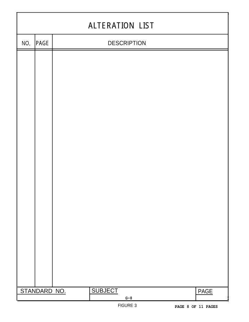
b. Each Livingston Standard.shall have an alteration list, when needed,in the format shown In Figure 3.
c. Each Livingston Standard shall have, when needed, a list of referencesin the format shown in Figure 4.
d. Each Livingston Standard shall have, when needed, a page for generalnotes in the format shown in Figure 5.
e. For pages of a Livingston standard that consist of typewritten matter,the format shown in Figure 6 shall be used.
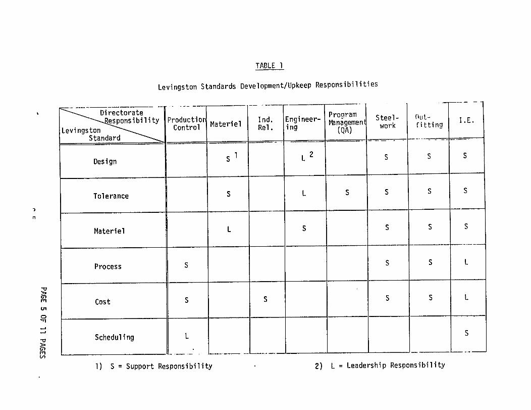
f. Formats for other pages will vary according to the subject and content.Directorates/Departments shall develop the formats for those standardsfor which they have been assigned leadership responsibility (see Table 1).At a minimum, each of those formats shall include an appropriate border,
the title or subject of the standard, the number of the standard, andthe page number. The standard page size shall be 81/2” x 11”. All other
sizes shall be held to a minimum but in any case shall be folded tomeet the 81/2” x 11” requirement.
7. (Review Committee Chairman) Reporting requirements. Each committeechairman shall report to the Systems & Procedures group at the end ofeach month on the status of their respective standards. A suggestedmethod is by stating the status on the cover sheet as shown in Figure 2.
PAGE NO. 4
STANDARD OPERATING PROCEDURE OF 11 PAGES
G-4FORM 20-005
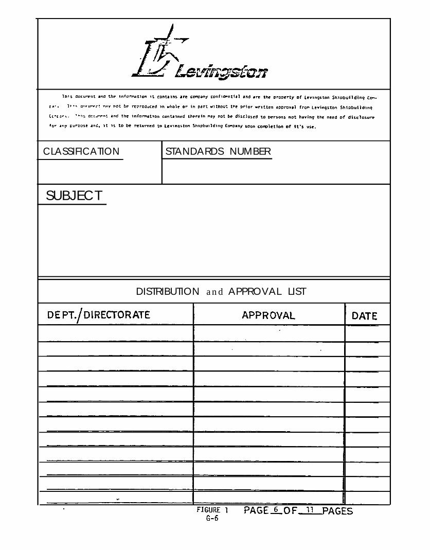
CLASSIFICATION STANDARDS NUMBER
SUBJECT
DISTRIBUTION and APPROVAL LIST

CLASSIFICATION
STANDARDSStatus 2/18/80: Awaiting USCG/ABS approval (chairman’s approval)
DISTRIBUTION and APPROVAL LIST
DE PT./ Directorate APPROVAL DATE
1
ALTERATION LIST
NO, PAGE DESCRIPTION
STANDARD NO. SUBJECT PAGEG-8 I
FIGURE 3 PAGE 8 OF 11 PAGES
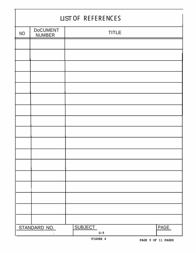
LIST OF REFERENCES
NODoCUMENTNUMBER TITLE
I
ISTANDARD NO. SUBJECT PAGE
. G-9
FIGURE 4 PAGE 9 OF 11 PAGES
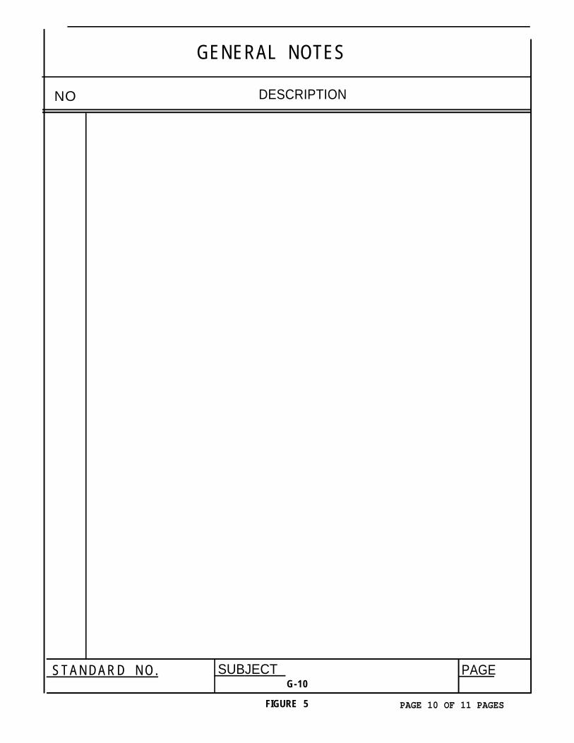
GENERAL NOTES
DESCRIPTIONNO
STANDARD NO. SUBJECT PAGEG-10
FIGURE 5 PAGE 10 OF 11 PAGES
REMARKS A L T .
4
STANDARD NO, SUBJECT PAGE,. G-11
FIGURE 6 PAGE 11 OF 11 PAGES