STANDARD SPECIFICATIONS FOR SUBSURFACE INVESTIGATIONS...
113
STANDARD SPECIFICATIONS FOR SUBSURFACE INVESTIGATIONS 2010
-
Upload
truongkhanh -
Category
Documents
-
view
231 -
download
3
Transcript of STANDARD SPECIFICATIONS FOR SUBSURFACE INVESTIGATIONS...

STANDARD SPECIFICATIONS FOR SUBSURFACE INVESTIGATIONS 2010

SECRETARIAT SANRAL PRIVATE BAG X 5 ALKANTRANT 0005

1
STANDARD SPECIFICATIONS
FOR
SUBSURFACE
INVESTIGATIONS
2010

2
FOREWORD
The need for an updated version of the original CSRA Standard Specification for Subsurface Investigations (1993) has been universally expressed by Geotechnical Engineers, Engineering Geologists and Drilling Contractors for a number of years. The South African National Roads Agency Limited (SANRAL) therefore took the initiative in 2006 to invite various individuals from the geotechnical consulting and drilling contracting fraternity to proactively contribute towards this task. This document is the end result of this reviewing and updating process. A decision was taken not to include standard specification sections for carrying out geophysical investigatory methods into this updated version, although it is fully realised and respected that geophysical investigative methods play an all important role in subsurface investigatory work. SANRAL wishes to thank the following persons involved in revising and updating this latest edition of the Standard Specifications for Subsurface Investigations (2010): Consulting Engineers and Engineering Geologists: Messrs AJ Stuart, GV Price, D Haskins, P Pretorius and Mrs O van der Merwe Drilling Contractors: Messrs H A Rossouw, N Mackintosh and D Rossiter Road Authorities: Messrs R Damhuis and EH Terblanche Feedback Any constructive comments and feedback for possible incorporation into future editions will be appreciated. Please email such feedback to SANRAL.

3
STANDARD SPECIFICATIONS FOR SUBSURFACE INVESTIGATIONS
CONTENTS Page Foreword ………………………………………………………………………………… i
4
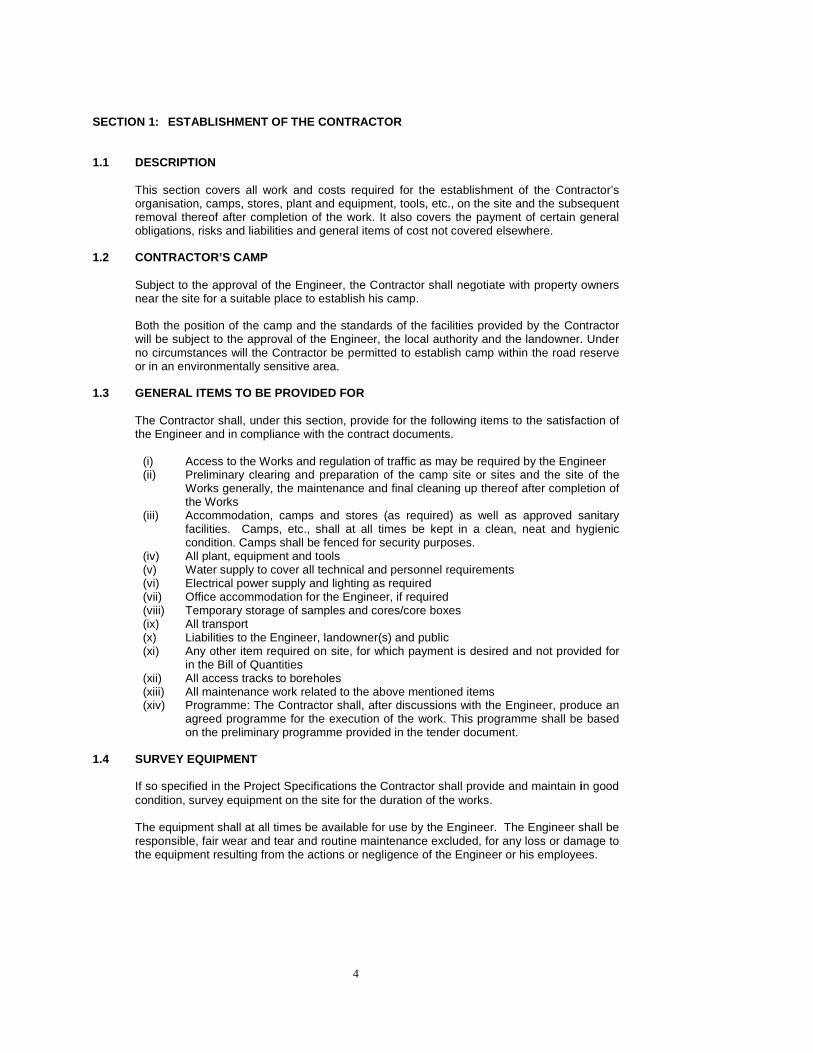
SECTION 1: ESTABLISHMENT OF THE CONTRACTOR 1.1 DESCRIPTION
This section covers all work and costs required for the establishment of the Contractor’s organisation, camps, stores, plant and equipment, tools, etc., on the site and the subsequent removal thereof after completion of the work. It also covers the payment of certain general obligations, risks and liabilities and general items of cost not covered elsewhere.
1.2 CONTRACTOR’S CAMP
Subject to the approval of the Engineer, the Contractor shall negotiate with property owners near the site for a suitable place to establish his camp. Both the position of the camp and the standards of the facilities provided by the Contractor will be subject to the approval of the Engineer, the local authority and the landowner. Under no circumstances will the Contractor be permitted to establish camp within the road reserve or in an environmentally sensitive area.
1.3 GENERAL ITEMS TO BE PROVIDED FOR
The Contractor shall, under this section, provide for the following items to the satisfaction of the Engineer and in compliance with the contract documents.
(i) Access to the Works and regulation of traffic as may be required by the Engineer (ii) Preliminary clearing and preparation of the camp site or sites and the site of the
Works generally, the maintenance and final cleaning up thereof after completion of the Works
(iii) Accommodation, camps and stores (as required) as well as approved sanitary facilities. Camps, etc., shall at all times be kept in a clean, neat and hygienic condition. Camps shall be fenced for security purposes.
(iv) All plant, equipment and tools (v) Water supply to cover all technical and personnel requirements (vi) Electrical power supply and lighting as required (vii) Office accommodation for the Engineer, if required (viii) Temporary storage of samples and cores/core boxes (ix) All transport (x) Liabilities to the Engineer, landowner(s) and public (xi) Any other item required on site, for which payment is desired and not provided for
in the Bill of Quantities (xii) All access tracks to boreholes (xiii) All maintenance work related to the above mentioned items (xiv) Programme: The Contractor shall, after discussions with the Engineer, produce an
agreed programme for the execution of the work. This programme shall be based on the preliminary programme provided in the tender document.
1.4 SURVEY EQUIPMENT
If so specified in the Project Specifications the Contractor shall provide and maintain in good condition, survey equipment on the site for the duration of the works.
The equipment shall at all times be available for use by the Engineer. The Engineer shall be responsible, fair wear and tear and routine maintenance excluded, for any loss or damage to the equipment resulting from the actions or negligence of the Engineer or his employees.
5
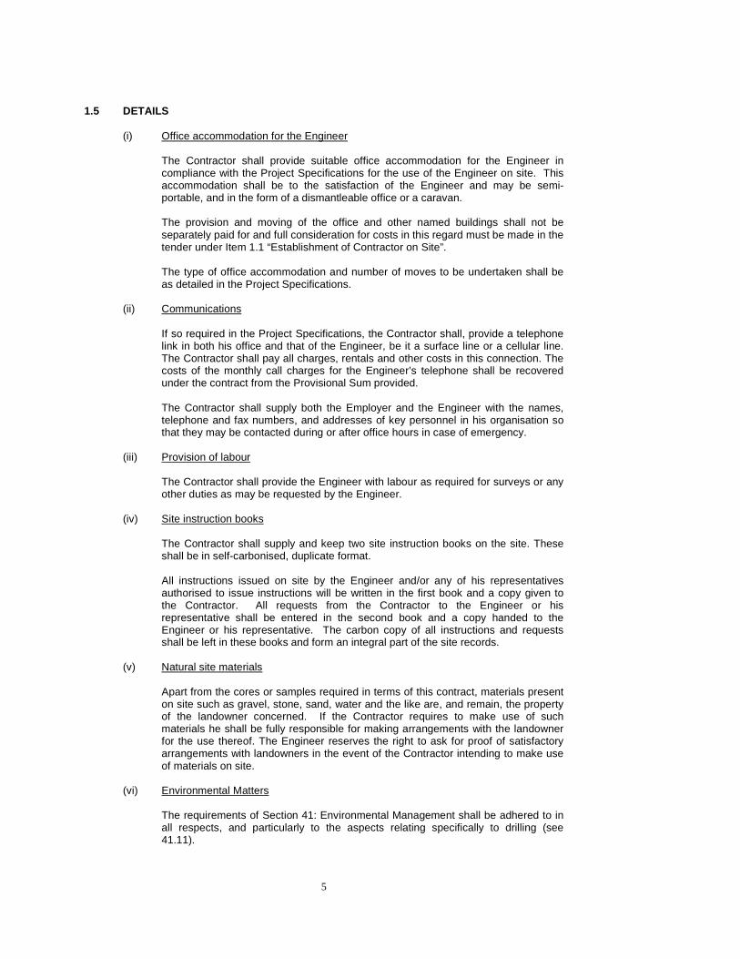
1.5 DETAILS
(i) Office accommodation for the Engineer
The Contractor shall provide suitable office accommodation for the Engineer in compliance with the Project Specifications for the use of the Engineer on site. This accommodation shall be to the satisfaction of the Engineer and may be semi-portable, and in the form of a dismantleable office or a caravan. The provision and moving of the office and other named buildings shall not be separately paid for and full consideration for costs in this regard must be made in the tender under Item 1.1 “Establishment of Contractor on Site”. The type of office accommodation and number of moves to be undertaken shall be as detailed in the Project Specifications.
(ii) Communications
If so required in the Project Specifications, the Contractor shall, provide a telephone link in both his office and that of the Engineer, be it a surface line or a cellular line. The Contractor shall pay all charges, rentals and other costs in this connection. The costs of the monthly call charges for the Engineer’s telephone shall be recovered under the contract from the Provisional Sum provided. The Contractor shall supply both the Employer and the Engineer with the names, telephone and fax numbers, and addresses of key personnel in his organisation so that they may be contacted during or after office hours in case of emergency.
(iii) Provision of labour
The Contractor shall provide the Engineer with labour as required for surveys or any other duties as may be requested by the Engineer.
(iv) Site instruction books
The Contractor shall supply and keep two site instruction books on the site. These shall be in self-carbonised, duplicate format. All instructions issued on site by the Engineer and/or any of his representatives authorised to issue instructions will be written in the first book and a copy given to the Contractor. All requests from the Contractor to the Engineer or his representative shall be entered in the second book and a copy handed to the Engineer or his representative. The carbon copy of all instructions and requests shall be left in these books and form an integral part of the site records.
(v) Natural site materials
Apart from the cores or samples required in terms of this contract, materials present on site such as gravel, stone, sand, water and the like are, and remain, the property of the landowner concerned. If the Contractor requires to make use of such materials he shall be fully responsible for making arrangements with the landowner for the use thereof. The Engineer reserves the right to ask for proof of satisfactory arrangements with landowners in the event of the Contractor intending to make use of materials on site.
(vi) Environmental Matters
The requirements of Section 41: Environmental Management shall be adhered to in all respects, and particularly to the aspects relating specifically to drilling (see 41.11).

6
(vii) Water quality
Only clean water, free from contamination (particularly in so far as this might lead to pollution or affect the quality of the cores and samples recovered), shall be employed. The Engineer shall approve all water used.
(viii) Clearance Certificates
The Contractor shall submit clearance certificates, as per Figure 1.1, obtained from the landowner(s) affected by the Contract, to the Engineer on completion of the work and before issue of the certificate of practical completion (see Section 39.3). These clearance certificates shall contain details of the works carried out on that property, with a statement that the landowner is satisfied with the remedial measures carried out.
1.6 LEGAL AND CONTRACTUAL REQUIREMENTS AND RESPONSI BILITIES TO THE
PUBLIC
The Contractor shall take all the necessary steps to comply with the Conditions of Contract, particularly in respect to the insurances and sureties required and his obligations to the public and the Employer. He shall comply with all the statutory regulations. The Contractor shall assess his obligations, and make allowances for the cost of compliance with this legislation. He shall take special note of the legislation relating to the government’s Broad Based Black Economic Empowerment Act. No separate payment shall be made for observing these requirements as it is deemed to be included in the amount tendered for under Section 1. The Contractor shall further assess his obligations in so far as the Occupational Health and Safety Act, and the appurtenant Construction Regulations that regulate the Contractor’s construction methods so as to ensure health and safety of his employees and of the public, Details of these obligations are given in Section 40.
1.7 EXTENSION OF TIME
The Contractor shall be entitled to claim for an extension of Time for Completion in terms of the Conditions of Contract which may be caused by inclement weather and consequential delays (“rain days”).
1.7.1 Extension of time resulting from inclement weather
Extension of time resulting from inclement weather shall be calculated according to the method as outlined below. A delay caused by inclement weather conditions (“rain days”) will be regarded as a delay only if, in the opinion of the Engineer, all progress by a drill or other rig on the working programme of the Contractor has been brought to a halt. Only delays on Working Days shall be taken into account for the extension of time. Rain days shall be agreed to between the Engineer and the Contractor for each Working Day on which at least 10mm of rain falls and on which the Contractor is unable to continue with his operations on site. Where, following rain days, conditions on site are such that the Contractor is unable to work safely and effectively, such days will also be counted as rain days. Rainfall shall be recorded on site at a gauge erected at the Contractor’s camp. Note that where there are multiple rigs on site and some of the units can continue to work, a rain day shall be measured in proportion to those rigs that cannot work relative to the total number of rigs on site. For example if 2 rigs out of a total of 5 rigs cannot work; 0.4 rain days shall be measured.

7
Rain days shall be measured and agreed to at the end of each month and no retrospective measurements will be allowed. Note the requirements of Section 39: Preparation of Records in this regard. Rain days shall be added to the contract period given in the contract to define the actual Time for Completion, as set out in the Conditions of Contract.
1.7.2 Programme
The Engineer shall provide in the Project Specifications the production rate (all-in metres per drill rig per Working Day) and number of drilling rigs that he has assumed in arriving at the Time for Completion in the preliminary programme in the project documentation. The Contractor shall provide the number of drill (and other) rigs necessary to complete the work within the Time for Completion. Under normal circumstances, taking into account factors such as average depths of holes, number and difficulty of set-ups, materials to be drilled, etc, the average all-in production rate for a coring rig will usually be between 5 and 8m per rig per Working Day .
1.8 ACCOMMODATION OF TRAFFIC
The accommodation of traffic on a project shall be carried out in accordance with the requirements of Section 1500 of the COLTO Standard Specifications for Road and Bridge Works for State Road Authorities and the South African Traffic Roads Signs Manual (Volume 2, Chapter 13). The specific requirements for individual contracts shall be detailed in the Project Specifications and appropriate pay items generated.
1.9 MEASUREMENT AND PAYMENT
The establishment of the Contractor on site shall be measured as two separate items;
(i) Fixed obligations
A lump sum to provide full compensation for the fixed part of the Contractor’s general obligations, i.e. that part which is substantially fixed and is not a function of the time required for the completion of the work, and includes the following: • Setting up and maintaining his organisation, personnel, camps,
accommodation, ablution and other facilities, offices and stores, and constructional plant and equipment on site, and their removal on completion of the contract. The Contractor shall be liable for any costs and obligations related to the occupancy of the camp site.
• Complying with the Conditions of Contract, including the effecting of insurances and providing the required sureties.
Payment shall be made as follows:
(a) Fifty (50) percent of the tendered amount shall become payable in the first
payment certificate after the Contractor has established his equipment and camp to the satisfaction of the Engineer, has made a substantial start to the execution of the works and the contract insurances are in force and effect. The Engineer may however make lesser payments in any payment certificate if the above provisions have not been met and shall then pay the balance up to 50 percent of the tendered amount when establishment is satisfactory.
(b) The next twenty (20) percent of the tendered amount is payable under the
payment certificate where the value of the work already done exceeds one half (1/2) of the tender sum (excluding VAT). The conditions regarding reduced payment as mentioned in (a) above, are also applicable here.
(c) The remaining thirty (30) percent of the tendered amount shall become
payable in the final payment certificate.

8
(ii) Time related obligations
This is a daily rate to provide full compensation for that part of the Contractor’s general obligations that are mainly a function of the time for completion of the work. Measurement shall be per day which shall mean Working Day, commencing on the day of the Site Handover, being the date on which access has been granted to the Contractor to Site. Working Day is defined as 7:00 to 17:00 on weekdays and 07:00 to 13:00 on Saturdays.
Payment of the time related portion of establishment shall be made after compliance with the requirements of clause (i) (a) above and shall continue until the Time for Completion of the works or the billed quantity, whichever is the greater. The Engineer may reduce or withhold payment under this item if the Contractor fails to comply with the requirements of the Specifications or Conditions of Contract related to his organisation and establishment.
(iii) Health and safety obligations
This shall be measured per Calendar Day (commencing on the day of the Site Handover) and continue to the Time for Completion and covers all costs related to improving construction methodologies in order to provide a relatively healthy and safe working environment, and allows the Contractor to make separate allowance for the cost of compliance with legislation.
(iv) Environmental management
This shall be measured as a lump sum and shall cover all the Contractor’s obligations as set out in Section 41 of these Specifications. Payment shall be made in instalments of 10% per month, with the balance being paid in the final payment certificate.
(v) Provision of labour This shall be measured per hour or part thereof for which the person is used by the Engineer and shall include all costs (transport, supervision, etc) necessary for him to carry out the tasks required by the Engineer.
(vi) Telephone for the Engineer Where required in the Project Specifications, the Contractor shall provide for the sole use of the Engineer a telephone (either fixed-line or mobile) capable of receiving telephone, fax and data signals. The prime cost of the supply and call charges shall be recovered monthly on provision of documentary proof of the actual cost thereof from the service provider. Alternatively, the Engineer may elect to employ his own telephone, in which case the prime cost of the calls/data transmission made in connection with the contract shall be paid. The Engineer shall provide documentary proof of the costs that are directly related to the project and provided by the Engineer and certified as being directly related to the contract.
9
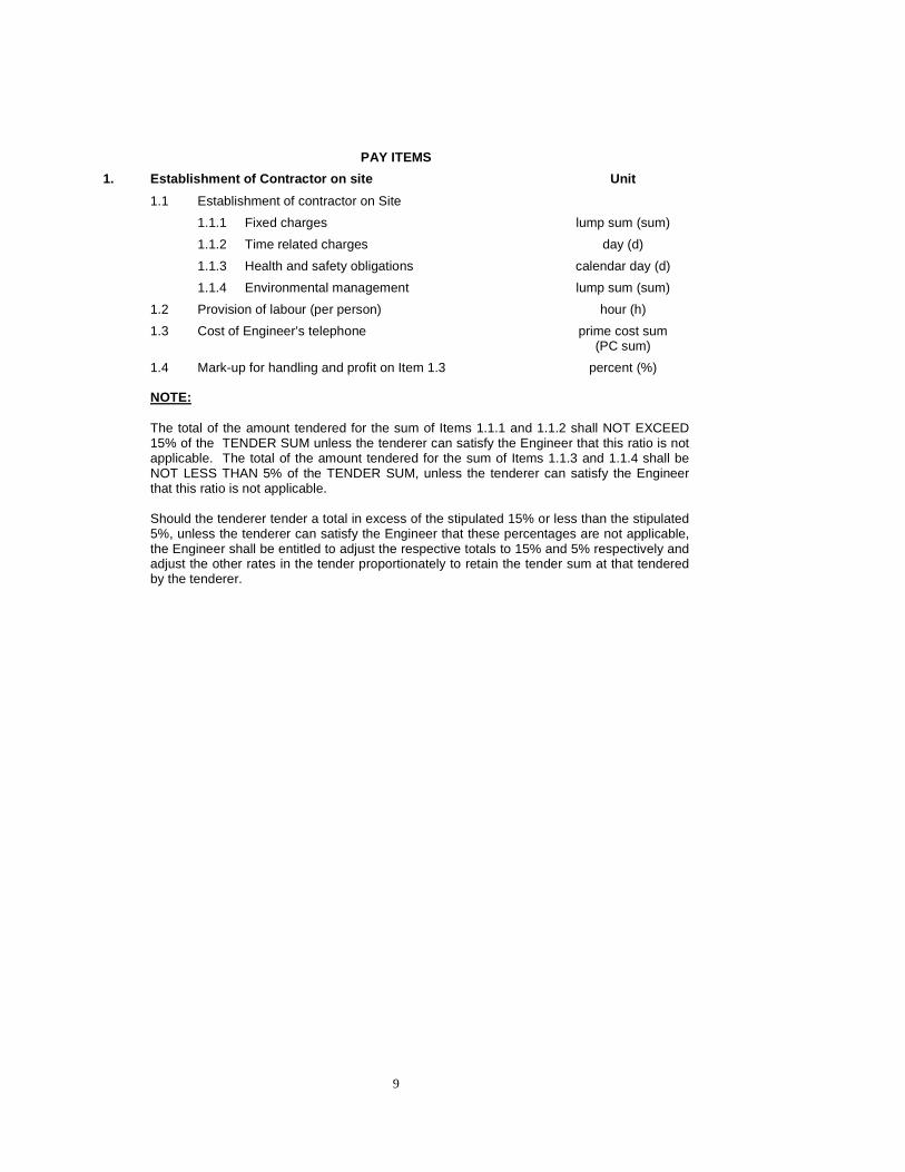
PAY ITEMS
1. Establishment of Contractor on site Unit
1.1 Establishment of contractor on Site
1.1.1 Fixed charges lump sum (sum)
1.1.2 Time related charges day (d)
1.1.3 Health and safety obligations calendar day (d)
1.1.4 Environmental management lump sum (sum)
1.2 Provision of labour (per person) hour (h)
1.3 Cost of Engineer’s telephone prime cost sum (PC sum)
1.4 Mark-up for handling and profit on Item 1.3 percent (%)
NOTE: The total of the amount tendered for the sum of Items 1.1.1 and 1.1.2 shall NOT EXCEED 15% of the TENDER SUM unless the tenderer can satisfy the Engineer that this ratio is not applicable. The total of the amount tendered for the sum of Items 1.1.3 and 1.1.4 shall be NOT LESS THAN 5% of the TENDER SUM, unless the tenderer can satisfy the Engineer that this ratio is not applicable. Should the tenderer tender a total in excess of the stipulated 15% or less than the stipulated 5%, unless the tenderer can satisfy the Engineer that these percentages are not applicable, the Engineer shall be entitled to adjust the respective totals to 15% and 5% respectively and adjust the other rates in the tender proportionately to retain the tender sum at that tendered by the tenderer.

10
(CONTRACTOR’S LETTERHEAD)
CONTRACT NUMBER: (Insert contract number)
CONTRACT NAME: (Insert Name)
CLEARANCE CERTIFICATE FARM NAME & No : ………………………………….…..
LANDOWNER (or authorised occupier) : ………………………….…………..
ADDRESS AND CONTACT DETAILS : ……………………………………...
………………………………………
(Tel) (………)…………………………. (Cell) ……...……………..
(Fax) (……….)…………………………….. (e-mail)…….…………...……
In respect of the work carried out on the named land, it is hereby certified as follows:
1 The access tracks, camp site (if applicable), borehole and other investigation positions, fences and gates and any other related aspects used by the Contractor for the purposes of the Contract have been fully treated and rehabilitated in accordance with the Contract and to the Owner/Occupier’s satisfaction.
2 The Contractor has concluded his operations, removed his equipment and left the land, access ways and general areas of the farm in a state that meets with the full satisfaction of the Engineer.
In respect of 1: .
Owner/Occupier……………………...Date…………………..………..Witness 1 …………………………
Contractor……………………..……...Date…………………….……..Witness 2 …………………………
Furthermore, in signing this clearance certificate, I undertake not to make any further claims to the Employer (insert Employer’s name) or the Contractor (insert Contractor’s name) with regards to the activities undertaken for the abovementioned contract and the condition of the property as specified. In respect of 2:
Engineer………………..………….….Date…………………….…………..
Witness 1 …………………………Witness 2 …………………………
Figure 1.1: Example of Clearance Certificate

11
SECTION 2 HOUSING FOR ENGINEER’S SITE STAFF 2.1 DESCRIPTION
Accommodation for the Engineer’s site staff may be required. The choice of accommodation will depend on the Engineer and shall be detailed in the Project Specifications.
2.2 MEASUREMENT AND PAYMENT
Payment shall be as a provisional sum item in accordance with the provisions of the Conditions of Contract. Reimbursement of the cost will be made only after acceptable proof of payment to the supplier by the Contractor has been provided to the Engineer.
PAY ITEMS
2. Housing for Engineer’s site staff Unit
2.1 Accommodation provisional sum (P sum)
2.2 Mark-up for handling and profit percent (%)

12
SECTION 3 ESTABLISHMENT AND PROVISION OF RIGS AND E QUIPMENT 3.1 DESCRIPTION
This section relates to the provision on site and subsequent removal of drilling rigs or plant and equipment necessary to complete the specified Works. It must be noted that the term “borehole” is a generic term used to denote all investigation positions. Details of the plant and equipment to be provided shall be given in the Project Specifications with respect to machine type and size, kW rating, bucket width, tracked or tyred, etc in order for the Contractor to source appropriate plant or equipment.
3.2 MEASUREMENT AND PAYMENT A drilling rig or equipment unit shall be regarded as established once it has been properly erected and commissioned and is in full working order, together with all equipment, tools, accessories and crew required to execute the particular work. The tendered rate shall include full compensation for providing the plant, transporting it to site, erecting, commissioning and finally dismantling it and loading and transporting it away from site. Measurement shall only be made in respect of Working Days on which the rig or equipment unit is in operation and in full working order for more than 75% of the Working Day (07:00 to 17:00 weekdays and 07:00 to 13:00 on Saturdays). Note that this implies that rain days will not be measured. No payments shall be made after the Time for Completion (see Section 39).
No drilling rig, plant or other equipment shall be brought onto, or removed from the site, without the written authority of the Engineer.
3.2.1 Provision of drilling rigs The quantity to be paid for under Items 3.1 to 3.2 shall be the product of the number of rigs and the duration of the time (measured per Working Day or part thereof on which they are working) for which they are required on site, authorised by the Engineer in writing, and brought onto site
3.2.2 Establishment of other plant and equipment
This shall be measured as a Lump Sum and shall cover the costs of establishing the required plant and equipment at the position where it is to be used, and the subsequent de-establishment thereof on completion of the works, or on instruction of the Engineer. The daily costs for the plant and equipment shall be provided for under the relevant sections, i.e. Section 6 Access, Section 19 Core Orientation Surveys, Section 26 Water Pressure Testing, Section 27 Grout Acceptance Testing and Section 36 Machine and Hand Trenching.
13
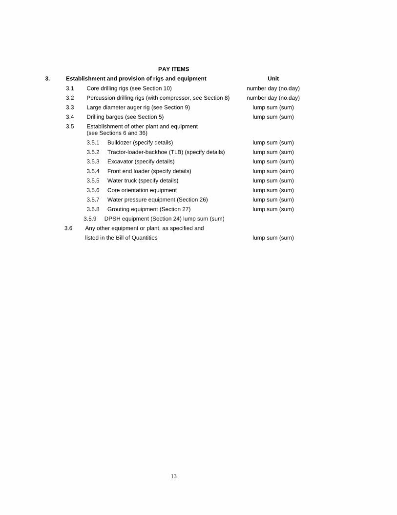
PAY ITEMS
3. Establishment and provision of rigs and equipmen t Unit
3.1 Core drilling rigs (see Section 10) number day (no.day)
3.2 Percussion drilling rigs (with compressor, see Section 8) number day (no.day)
3.3 Large diameter auger rig (see Section 9) lump sum (sum)
3.4 Drilling barges (see Section 5) lump sum (sum)
3.5 Establishment of other plant and equipment (see Sections 6 and 36)
3.5.1 Bulldozer (specify details) lump sum (sum)
3.5.2 Tractor-loader-backhoe (TLB) (specify details) lump sum (sum)
3.5.3 Excavator (specify details) lump sum (sum)
3.5.4 Front end loader (specify details) lump sum (sum)
3.5.5 Water truck (specify details) lump sum (sum)
3.5.6 Core orientation equipment lump sum (sum)
3.5.7 Water pressure equipment (Section 26) lump sum (sum)
3.5.8 Grouting equipment (Section 27) lump sum (sum)
3.5.9 DPSH equipment (Section 24) lump sum (sum)
3.6 Any other equipment or plant, as specified and
listed in the Bill of Quantities lump sum (sum)
14
SECTION 4 SETTING OUT AND SURVEY 4.1 DESCRIPTION
This section relates to the setting out of boreholes and related survey. The boreholes shall be located at the positions as indicated on the drawings supplied, or as detailed in writing by the Engineer. The extent of the work involved in setting out and surveying in and details of the beacons established by the Engineer in accordance with the Conditions of Contract, is given in the Project Specifications. The Contractor shall provide on site a hand-held GPS, which he shall use for the initial setting out of borehole positions. The GPS shall be capable of reading and storing co-ordinates to WGS84 in accordance with the South African Grid System (X and Y co-ordinates in metres) and also in degrees, minutes and 3 decimals of a minute. The co-ordinates of any borehole set out by the Contractor shall be recorded on the Daily Drilling Journal (see Section 39) and a schedule of these shall be provided separately to the Engineer. No payment will be made for this work and the Contractor shall allow for this in his rates. The Contractor shall take all steps necessary to protect existing survey pegs, reference pegs and bench marks and shall re-establish such at his own expense and to the satisfaction of the Engineer should they be disturbed as a result of his activities on site. The Engineer will indicate the direction and the inclination of all boreholes to the Contractor. Where inclined drilling is required, the initial setting out of the hole shall be carried out using a GPS and compass to the direction and inclination (degrees below horizontal), as provided by the Engineer. The actual direction and inclination of the hole shall be determined by the following method:
• Once the hole has been drilled to about 5m depth, insert drill rods into the hole such that they extend at least 3m out of the top of the hole
• Sight along the direction of the rods and place two reference pegs (steel peg in 200 x 200 x 200mm concrete block, co-ordinated using the GPS) on the line of the hole. These reference pegs to be 3 and 8m from the hole.
• Measure this direction using a compass • Measure the inclination of the rods using a clino-compass or similar to an accuracy
of 1° (degrees below horizontal) Where the accuracy of setting out of an inclined hole is critical, the Engineer may order that the azimuth shall be set out by a professional surveyor. A surveyor approved of or selected by the Engineer shall carry out any accurate levelling and co-ordination in accordance with the requirements of TMH 11.
4.2 MEASUREMENT AND PAYMENT
Any survey work by a surveyor instructed by the Engineer shall be paid by means of a Provisional Sum. Reimbursement for the cost will be made only after the Contractor has provided to the Engineer acceptable proof of payment to the supplier.
PAY ITEMS
4. Setting out and survey Unit
4.1 Setting out and survey provisional sum (P sum)
4.2 Mark-up for handling and profit percent (%)

15
SECTION 5 SETTING UP 5.1 DESCRIPTION
This section relates to the setting up of individual drilling, augering and other investigatory equipment and subsequent removal after completion of the work. The rates tendered shall be deemed to include for the access of personnel and transport to and the subsequent removal of labour, plant or any other incidentals necessary for the operations from each borehole. Distinction shall be made between the methods and degree of difficulty of setup at each borehole using the following criteria: Setup method
Skid setup Accessible by 4 x 4 Ground slope
Distance to be winched from nearest offloading position
Mobile Yes Normal No <1:3 <100m Difficult No >1:3 >100m
Skid
Very difficult No >1:2 >200m The method of setup at any borehole shall define the payment rate under which the setup and removal shall be made, but shall be subject to the approval of the Engineer. Should the Contractor utilise a setup method different to that specified and approved by the Engineer, payment shall be made according to the type originally specified, unless the Contractor can prove to the Engineer’s satisfaction that the use of the setup method originally specified was impractical. In this regard the Contractor should note the following:
(a) The provisions of Section 6 “Access”; (b) Some hand clearing of rocks and bush, as may be classified as reasonable by the
Engineer, to obtain access to a mobile setup position may be required. If unreasonable clearing is required this will be paid for in accordance with the relevant items under Section 6 or under Item 1.2, Provision of Labour, as may be decided by the Engineer;
(c) If it is necessary to dismount the rig from the crawler, trailer, truck, etc., at the
position of the borehole to carry out the actual boring operation, this will be measured as a mobile setup;
(d) The grouping (if any) of boreholes according to the difficulty to access given in the
Project Specifications or in the Bill of Quantities.
Rigs shall be securely anchored to be able to provide the necessary reaction to drilling and to prevent movement of the rig relative to the borehole. For inclined boreholes (as defined in Section 10) it may be necessary to provide a concrete drilling platform to which the rig is anchored and a suitable tripod. On completion of drilling, all platforms, benches and any other facilities created by the Contractor shall be entirely removed or reinstated, all to the satisfaction of the Engineer. Where piled drilling platforms, embankments, coffer dams and other similar techniques are required for boring over water or in positions necessitating their construction, they shall be securely and rigidly constructed and capable of withstanding all loads and thrusts generated by the plant and equipment to be operated on them. Upon completion they shall be completely dismantled and removed, including any supports that may have been driven into the underwater bed, to the satisfaction of the Engineer. Where drilling is carried out from a barge or pontoon this shall be securely anchored to prevent drifting and, if necessary, to provide the necessary reaction to drilling forces. The tendered rates shall take into account the specific requirements as set out in the Project Specifications.
16
No dug sumps are permitted and drum sumps must be used, except in exceptional circumstances and then, only with the specific approval of the Engineer for individual boreholes. Before drilling commences at any hole, the Engineer’s approval of the setting up of the rig will be required and after completion of the hole, the rig shall not be removed without he Engineer’s approval. For this approval before and after drilling of the hole, the Contractor must allow the Engineer, except if other arrangements have been negotiated, a waiting time of one hour (for each occurrence) before any Standing Time may be claimed in accordance with Section 37.
5.2 MEASUREMENT AND PAYMENT
The setups ordered by the Engineer shall be measured by number for the method of setup employed. Setting up on inclined holes shall be measured extra over the relevant setup item. Setting up on drilling barges, piled platforms and other specialised circumstances shall be measured separately as stated in the Project Specifications. Movement of rigs between boreholes: The first kilometre shall be deemed to be included in the rates for setting up. For boreholes more than 1 km apart the unit of measurement for the distance moved (by the shortest practicable route, as approved by the Engineer) shall be per kilometre (measured to the nearest 0.1km) by which the distance exceeds 1km and shall be extra over the setup rate.
Besides the different set-up categories as listed below, distinction may be made between
different categories of boreholes (as regards difficulty of access) as specified in the Project Specifications or reflected in the Bill of Quantities.
PAY ITEMS
5. Setting up Unit
5.1 Mobile setups
5.1.1 Core drill number (no.)
5.1.2 Percussion drill number (no.)
5.2 Skid setups
5.2.1 Normal skid setups number (no.)
5.2.2 Difficult skid setups number (no.)
5.2.3 Very difficult skid setups number (no.)
5.3 Setting up on inclined holes
Extra over 5.1 or 5.2 number (no.)
5.4 Setting up in specialised circumstances
Extra over 5.1 or 5.2 (specify type) number (no.)
5.5 Movement between boreholes
Extra over 5.1 or 5.2 (specify rig type) kilometre (km)
17
SECTION 6 ACCESS 6.1 DESCRIPTION
To obtain access to some borehole positions, access tracks may have to be constructed by the Contractor. The plant to be used shall be agreed with the Engineer. Only one track shall be permitted to obtain access to any investigation position and the Engineer shall approve the alignment of such tracks. Wherever possible, the access tracks shall follow contours and shall avoid large shrubs, trees and sensitive areas such as wetlands, mangroves, dunes, stream banks and other areas subject to erosion. Entry points of these access tracks should, if possible, be obscured by using doglegs or stony patches to discourage unauthorised use.
Clearing of vegetation shall be kept to a minimum. Low vegetation should rather be driven over and rolled in in preference to bulldozing so as to keep the root stock. In the event that an access track is bulldozed, the topsoil should be stockpiled and any cleared indigenous vegetation piled on top of the topsoil stockpiles in order to redistribute seeds during rehabilitation.
Particular attention shall be paid to the landowner’s requirements and the tracks’ impact on the environment.
On completion of use of such access tracks, they shall be reinstated as soon as practicable, as described in Section 41, or as directed by the Engineer. The extent of this reinstatement work, and any payment therefore, shall be as detailed in the Project Specifications It must be noted that where the Contractor has taken insufficient care during the contract and has used more than one track to a borehole, this reinstatement shall not be measured and paid for.
Where access tracks are required to be built, these may be constructed using:
• Bulldozer • Tractor-loader-backhoe (TLB) • Excavator • Other equipment as required
The capacities, sizes and power ratings for individual units of plant shall be detailed in the Project Specifications.
6.2 MEASUREMENT AND PAYMENT
Measurement and payment shall be on a daily (10 hour) basis per Working Day during which the machine is on site in working order and shall include the cost of the hire of the plant, fuel, the operator, supervision by the Contractor and all other incidental costs. Should the machine break down for more than an hour in any one day, payment for that day shall be reduced proportionately relative to the time when the machine was operative, with the provision that should it be inoperative for more than 4 hours in any one day, it shall not be measured at all for that day. Establishment of the machine on site shall be measured and paid for under Section 3. Reinstatement of access tracks shall be measured as a lump sum and shall include all costs and incidentals necessary to carry out the reinstatement, as detailed in the Project Specifications.

18
PAY ITEMS
6. Access tracks Unit
6.1 Making of access tracks using different types of equipment as given in the Bill of Quantities
6.1.1 Bulldozer (specify details) day (d)
6.1.2 Tractor-loader-backhoe (TLB) (specify details) day (d)
6.1.3 Excavator (specify details) day (d)
6.1.4 Front end loader (specify details) day (d)
6.1.5 Water truck (specify details) day (d)
6.1.6 Other equipment as required day (d)
6.2 Reinstatement of access tracks lump sum (sum)

19
SECTION 7 CUTTING DOWN OF TREES AND CROPS 7.1 DESCRIPTION
Where setting up at a drilling, testing or auger site or the provision of access thereto involves the cutting down and removal of trees, or the destroying of crops, such trees shall only be cut down or the crops destroyed on the written instructions of the Engineer and after written approval and agreement has been reached with the landowner concerned. In the case where trees and crops have to be destroyed, compensation to the landowner for the loss of trees of commercial value and crops and damage at a reasonable price agreed to by the landowner, and approved by the Engineer, shall be paid by the Contractor and recovered under the contract. Payment to the Contractor shall be made only upon production of a receipt, signed by the landowner, indicating proof of payment to the landowner and the landowner’s acceptance of the compensation paid to him. The Contractor shall measure the area (in hectares) and shall be responsible for the physical destruction and removal of the crops.
All trees, shrubs or vegetation destroyed by the Contractor without the Engineer’s approval shall be recompensed to the satisfaction of the landowner and Engineer at the Contractor’s cost.
7.2 MEASUREMENT AND PAYMENT
Clearing of trees of less than 150mm in diameter and bush shall be included in the rates tendered by the Contractor in Sections 1, 5 and 6. For trees greater than 150mm in diameter the measurement and payment for the cutting down and removal thereof shall be per number, with distinction being made between trees of diameter between 150 and 300mm and trees of diameter greater than 300mm. For measurement purposes the diameter of any tree shall be measured at a height of 1m above general ground level at the location of the tree involved. The unit of measurement for the destruction and removal of crops shall be per hectare and payment of compensation to landowners shall be made under a provisional sum. Reimbursement for the cost will be made only after the Contractor has provided to the Engineer acceptable proof of payment to the supplier.
PAY ITEMS
7. Cutting down of trees and crops Unit
7.1 Cutting down of trees and removal thereof
7.1.1 Between 150 and 300mm diameter number (no.)
7.1.2 Greater than 300mm diameter number (no.)
7.2 Destruction of crops hectare (ha)
7.2.1 Compensation to landowner provisional sum (P sum)
7.2.2 Mark up for handling and profit percent (%)

20
SECTION 8 PERCUSSION DRILLING 8.1 DESCRIPTION
This section relates to drilling by means of a compressed air or similar type percussion rig, including an appropriate compressor, as approved by the Engineer. The Contractor shall provide details with his tender of the drill rig and the make and capacity of the compressor. The size to be drilled shall be between 100 and 250mm diameter (as given in the Project Specifications) and the rig shall employ a down-the-hole hammer. The drilling may be:
• Conventional open hole drilling – where a bottom discharge hammer is used and the sample passes up between the drill pipe and the wall of the hole.
• Reverse circulation (RC) drilling – where a dual wall drill pipe is used and the sample passes up the outer annulus (air in the inner annulus). A centre sample hammer may be used which has a hollow centre and the sample passes directly into the the dual wall pipe. If a conventional hammer is used, the sample has to travel up and enter a vertical slot set above the hammer.
• Symmetrix drilling where the casing is installed as drilling proceeds and the sample passes up through the hammer (see RC drilling above).
Sophisticated data recorders (such as the Jean Lutz system) are available to record drilling parameters such as torque, penetration speed, bit pressure, etc (up to 7 parameters can be recorded simultaneously). The Engineer may order that such a recorder be coupled to the percussion rig where it is appropriate to record these parameters in order to facilitate interpretation of subsurface conditions. This technique will normally only be used in dolomitic terrain where conditions are highly variable. If, during percussion drilling, underground cavities are encountered, the depth thereof below ground level shall be carefully measured, as shall the depth to the bottom of the cavity. The Engineer shall immediately be notified of the existence of such cavities or cracks wider than 100mm. No payment shall be made for the recovery of washings and chips blown out during drilling and allowance shall be made under this item for any costs thus incurred. Blow-out samples shall be bagged and labelled as follows:
• From each metre drilled. A representative sample (minimum 250g) of the washings and chips blown out during percussion drilling shall be collected. These shall be placed into a plastic bag (nominal 250 x 200mm, 20µ) as follows:
o Shake sample into corner of bag o Twist bag 3 times to seal off the sample from the record ticket o Turn bag inside out o Place record ticket into the bag so that it can be read from the outside o Twist off the bag (3 turns) and turn it inside out again. o The record ticket shall reflect the project and site name, borehole number,
depth range and penetration speed (minutes and seconds). This data shall be in indelible, waterproof writing. If a ticket becomes illegible, the contractor may be required to redrill the hole at his cost.
• Of each borehole. On completion of a borehole, the samples from an individual borehole, in depth sequence, shall be inserted into a separate plastic sleeve (nominal 100mm diameter and 50µ thick), which is tied off at each end. The site, borehole number and final hole depth shall neatly and legibly be written onto the sleeve in indelible pen (minimum 3mm thick).
The time of penetration shall be measured for each metre penetrated and recorded on an approved form. The time for penetration shall be measured with a stopwatch to an accuracy of better than 5 seconds for each metre drilled and shall be the actual drilling time and shall not include time when the bit is jammed, adding of rods, etc. No payment shall be made for the time recording and allowance must be made under other items for the costs incurred.

21
Holes drilled in dolomitic terrain shall be backfilled with a soil-cement mortar (using the material blown out of the hole and 5% cement), with a 6:1 sand/cement plug in the uppermost 2m. The borehole number shall be scratched into surface of the plug. In non-dolomitic terrain a nominal 6:1 soil-cement plug shall be placed in the uppermost 2m of the borehole.
8.2 RECORDING OF WATER REST LEVEL
If water is encountered in holes drilling on dolomitic sites, the water rest level must be accurately measured. Should the Engineer so instruct, the water rest level shall be measured at 24 hour intervals until it has stabilised. In this case, a 25mm ID uPVC pipe (slotted and with a geotextile sock over the lowermost 1m) shall be inserted to the full depth of the hole and the annulus between the hole wall and the pipe backfilled with sand.
8.3 PERCUSSION DRILLING JOURNAL (PDJ)
The purpose of this sheet is to act as a written communication between the Contractor and the Engineer. The report sheet contains valuable operational and performance data and shall be submitted to the Engineer on a daily basis. Figure 8.1 gives an example of a PDJ.
8.4 MEASUREMENT AND PAYMENT
The quantity to be paid for shall be per linear metre actually drilled, including cavities through which drilling may have been conducted with percussion equipment, measured from the mean ground level in the immediate vicinity of the drill hole. Measurement shall differentiate between the type and diameter of the drilling employed. Inclined drilling (at angles between horizontal and 85⁰) shall be measured extra over the rate for vertical drilling. Backfilling and plugging (if required) shall be measured separately. No separate payment will be made for the measuring of water rest levels. The rates shall include for the recording of the drilling operations in accordance with the PDJ and for the taking, labelling and rendering of samples of chips, as required, to the Engineer. Furthermore, distinction shall be made between the various depths at which percussion drilling is carried out, in increments of 50m Casing shall be measured per metre of casing installed and shall differentiate between casing installed temporarily and removed after completion of the hole (“casing in-and-out”) and casing left in the hole on the instructions of the Engineer. Casing installed in the hole shall be measured per linear metre and shall include for removal, where applicable, after completion of drilling. Where uPVC piping is installed, the rate shall include for installing the sand annulus. Where foam is added to improve sample recovery, it shall be measured in litres.

22
PAY ITEMS
8. Percussion drilling Unit
8.1 Percussion drill (specify type and diameter of drilling)
8.1.1 Percussion drilling (in 50m increments)
8.1.2 Inclined drilling (Extra Over Item 8.1.1.)
metre (m)
8.2 Backfilling hole metre (m)
8.3 Cement plug in uppermost 2m metre (m)
8.4 Percussion casing
8.4.1 Casing in-and-out metre (m)
8.4.2 Casing left in the hole metre (m)
8.4.3 Permanent casing (25mm ID uPVC)
8.4.3.1 Supply of casing metre (m)
8.4.3.2 Installation of casing (including sand annulus)
metre (m)
8.5 Addition of foam litre (ℓ)
NOTE: Payment for the establishment of drilling rigs and compressors is covered under Section 3 and setting up under Section 5 (mobile setups only). Standing time shall be paid in accordance with Section 37 .

23
PERCUSSION DRILLING JOURNAL Date ...................................................................
Client.................................................................. Project/Site ........................................................ Hole no............................................................... Total depth......................................................... Inclination/Bearing .............................................
Contractor ..................................................................... Casing in & out (m) ....................................................... Casing installed (m) ...................................................... Casing permanently damaged (m) ...............................
Rig ...................................................................................... Air pressure ........................................................................ Air capacity ......................................................................... Bit diameter (mm)............................................................... Water struck (m & ℓ) ........................................................... Water rest level (m) ............................................................
Formation
Hammer action
Air loss Moisture condition
Casing Sample
recovered
Depth (m)
Pen. time min/s
Cav
ity
Very so
ft
Soft
Fairly
ha
rd
Solid
Very irreg
ular
Irregu
lar
Reg
ular
Non
e
Slight
Med
ium
Total
Water struc
k
Wet
Moist
Dry
Hole co
llaps
es
Water/foa
m add
ed
Dep
th
Goo
d
Med
ium
Poo
r
Non
e
REMARKS (e.g. type of material)
0-1
1-2
2-3
3-4
4-5
5-6
6-7
7-8
8-9
9-10
10-11
11-12
12-13
13-14
14-15
15-16
16-17
17-18
18-19
19-20
20-21
21-22
22-23
23-24
24-25
25-26
26-27
27-28
28-29
29-30
Remarks................................................................................................................................................................................................................ .............................................................................................................................................................................................................................. .............................................................................................................................................................................................................................. DATA DESCRIPTION BY:.................................................................................................................................................................................... OPERATOR:.........................................................................................................................................................................................................
Figure 8.1 : Example of typical Percussion Drilling Journal
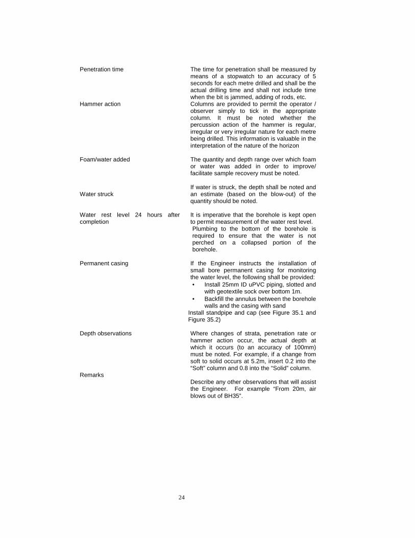
Explanatory notes to PDJ:
24
Penetration time The time for penetration shall be measured by
means of a stopwatch to an accuracy of 5 seconds for each metre drilled and shall be the actual drilling time and shall not include time when the bit is jammed, adding of rods, etc.
Hammer action
Columns are provided to permit the operator / observer simply to tick in the appropriate column. It must be noted whether the percussion action of the hammer is regular, irregular or very irregular nature for each metre being drilled. This information is valuable in the interpretation of the nature of the horizon
Foam/water added Water struck
The quantity and depth range over which foam or water was added in order to improve/ facilitate sample recovery must be noted. If water is struck, the depth shall be noted and an estimate (based on the blow-out) of the quantity should be noted.
Water rest level 24 hours after completion
It is imperative that the borehole is kept open to permit measurement of the water rest level. Plumbing to the bottom of the borehole is required to ensure that the water is not perched on a collapsed portion of the borehole.
Permanent casing
If the Engineer instructs the installation of small bore permanent casing for monitoring the water level, the following shall be provided: • Install 25mm ID uPVC piping, slotted and
with geotextile sock over bottom 1m. • Backfill the annulus between the borehole
walls and the casing with sand Install standpipe and cap (see Figure 35.1 and Figure 35.2)
Depth observations Remarks
Where changes of strata, penetration rate or hammer action occur, the actual depth at which it occurs (to an accuracy of 100mm) must be noted. For example, if a change from soft to solid occurs at 5.2m, insert 0.2 into the “Soft” column and 0.8 into the “Solid” column. Describe any other observations that will assist the Engineer. For example “From 20m, air blows out of BH35”.

25
SECTION 9 AUGERING 9.1 DESCRIPTION
This section relates to the drilling of holes by means of an approved augering system, as required in the Project Specifications, where so required by the Engineer.
9.1.1 Sampling of small diameter auger holes (<200mm diameter)
During augering carried out using a small diameter auger flight on a core drilling rig, continuous samples of the augered material shall be recovered, inserted into plastic sleeves approximating N-size diameter core and sealed. The depth of extraction shall be marked onto the plastic and placed in sequence into a core box. No additional payment shall be made for such sampling.
9.1.2 Sampling of large diameter auger holes (>200mm diameter) During augering using a separate, large diameter auger rig, a grab sample shall be taken from the bottom of the flight each time the flight is withdrawn and laid out in depth sequence next to the hole for the Engineer’s inspection. The Engineer may order that samples be taken from various horizons for testing and these shall be measured and paid for in accordance with Section 16.
9.1.3 Backfilling of holes No separate payment will be made for the backfilling of small diameter holes. Large diameter auger holes shall be backfilled to the satisfaction of the Engineer and allowance for compaction of the backfilled material shall be made. All material removed from the hole shall be heaped above the hole and, if the backfill settles more than 300mm below the surrounding ground level, the Contractor shall source and compact such additional material to fill up to ground level. Any settlement which occurs within one month of completion of the hole or the completion of the Works (whichever is the longer) shall be the Contractor’s responsibility. Any spoil left over after augering shall be disposed of and the area around the hole tidied, as ordered by the Engineer. Backfilling of, and tidying up around auger holes, shall not be paid for separately, except where the Engineer instructs that backfilling of an auger hole is to be delayed until after the auger rig has left the position of the hole or its vicinity.
9.2 SAFETY EQUIPMENT The large diameter augering shall be carried out in accordance with “Code of practice: The safety of persons working in small diameter shafts and test pits for civil engineering purposes” as produced by the Geotechnical Division of SAICE.
The Contractor shall provide safety equipment as described in the above document for each large diameter auger operating on site, to the satisfaction of the Engineer. The Engineer shall not allow augering to commence unless all the safety equipment is on site, in working order and at least one person who is familiar with the use thereof, is present at each auger rig. The Contractor may be required to provide additional sets of profiling and safety equipment as detailed in the Project Specifications. Such sets shall be measured and paid for per set per Working Day for which they are required on site on the written instruction of the Engineer.
26
9.3 MEASUREMENT AND PAYMENT
Payment for augering using small diameter equipment shall be per linear metre and shall include for all equipment and personnel necessary for the execution thereof. The unit of measurement for large diameter augering shall be a daily rate per Working Day (10 hours per day) for each Working Day that the rig is on site in working order, as required by the Engineer. The rate shall include all the operational requirements of the rig, setups, personnel, safety and profiling equipment, backfilling of the holes, and its subsequent de-establishment. If the Engineer instructs that backfilling of large diameter auger holes be delayed until after the auger rig has left the position of the hole or its vicinity, this shall be measured for each meter length of auger hole backfilled to the satisfaction of the Engineer, irrespective of the depth or diameter of the hole.
PAY ITEMS
9. Augering Unit
9.1 Small diameter augering (<200mm diameter) metre (m)
9.2 Large diameter augering (>200mm diameter)
9.2.1 Daily rate hire day (d)
9.2.2 Backfilling of hole (only when delayed by Engineer) metre (m)
9.3 Additional safety equipment as detailed in Project Specifications
day (d)
NOTE: Establishment of the large diameter auger rig is measured under Section 3.
27
SECTION 10 ROTARY CORE DRILLING 10.1 DESCRIPTION
This section relates to rotary core drilling through various categories of weak and strong material. Weak material in general comprises material from which samples may be obtained by means of a small diameter auger fitted to the drilling rig and all other material, which requires the use of diamond or tungsten bits, shall be considered to be strong material. Unless specified to the contrary, all drilling in material classified as weak or weathered rock shall be carried out using a split-inner, double-tube, swivel type core barrel (such as NWD4) to permit full core recovery. In strong material a conventional double-tube, swivel type core barrel may be employed. Single tube core barrels may not be used. At the commencement of drilling each hole, the Engineer shall indicate to the Contractor the depth to which the hole is to be drilled. The Engineer, however, reserves the right to vary the required depth of the hole at any stage during the drilling of that hole. To prevent undue delays, the Contractor shall give the Engineer reasonable notice when he anticipates that the required depth will be reached in any particular hole, but in any case, no drilling rig shall be dismantled and moved away from any particular hole on reaching the required depth until the Contractor is notified in writing by the Engineer that the drilling rig may be moved. The Engineer may order the re-establishment of any drilling rig moved away without his written authority, and such work shall then be carried out at the Contractor’s expense and no further payment for setting up the drilling rig will be made. Authority to move a rig on completion of drilling shall not be withheld unreasonably. The Contractor shall be entitled to “standing time” according to Section 37, should the delay of authority to move a drilling rig after drilling has been completed at a hole, exceed one hour. Each drilling rig used on the Contract by the Contractor shall be in the charge of a competent drilling supervisor, who shall be capable of completing the Daily Drilling Journals (DDJ), and be experienced in drilling in the types of formation expected on the site. Continuous core recovery shall, unless otherwise specified by the Engineer, be obtained whenever possible in both hard and soft material. In general, all drilling shall be N size. Inclined holes shall be defined as all holes ordered to be drilled with an inclination of between the horizontal and 85º. If the drilling equipment should become stuck or lodged in a borehole, or if, for any other reason, further drilling is not possible in that hole, the Contractor must immediately notify the Engineer and the Engineer will then decide if: (i) the hole is drilled deep enough to be acceptable, in which case payment for drilling
to the depth reached will be made; (ii) The depth drilled is insufficient, and that a new hole shall have to be drilled, in which
case no payment will be made for the unsatisfactory hole, unless the stoppage is due to unforeseen subsoil or geological conditions. In such case payment will be made for both the abandoned hole and the new hole. The Engineer shall in this event have due regard to the conditions encountered in already completed holes and the precautions taken by the Contractor to prevent loss of the hole.
The Contractor shall, unless specified to the contrary in the Project Specifications, provide a point load apparatus for the testing of cores. The apparatus which is equipped with a digital readout, together with a current certificate of calibration from an approved source, shall be to the satisfaction of the Engineer.
On completion of any drill hole, the hole shall be sealed and made safe to the satisfaction of the Engineer in accordance with Sections 28, 29 or 35 or as detailed in the Project Specifications.
28
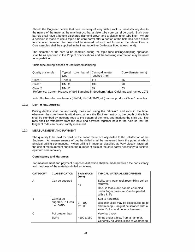
Should the Engineer decide that core recovery of very friable rock is unsatisfactory due to the nature of the material, he may instruct that a triple tube core barrel be used. Such core barrels shall have a bottom discharge diamond crown and a plastic inner tube liner. Where a decision is made to use a triple tube core barrel after a portion of the hole has been drilled to a smaller diameter, the hole shall be reamed out and paid for under the relevant items. Core samples shall be supplied in the inner tube liner (with caps fitted at each end). The diameter of the core to be sampled during the triple tube drilling/sampling operation shall be as specified in the Project Specifications and the following information may be used as a guideline. Triple tube drilling/classes of undisturbed sampling
Quality of sample Typical core barrel type
Casing diameter required (mm)
Core diameter (mm)
Class 1 Triefus 111 75
Class 1 HMLC 139 70
Class 2 NMLC 89 53 Reference: Current Practice of Soil Sampling in Southern Africa. Giddiings and Kantey 1976 Note: Double tube core barrels (NWD4, NXCM, TNW, etc) cannot produce Class 1 samples.
10.2 DEPTH RECORDING Drilling depths shall be accurately measured using the “stick-up” and rods in the hole, whenever the core barrel is withdrawn. Where the Engineer instructs, the depth of the hole shall be plumbed by inserting rods to the bottom of the hole, and marking the stick-up. The rods shall be withdrawn from the hole and screwed together next to the hole so that the length of rods can be accurately measured.
10.3 MEASUREMENT AND PAYMENT
The quantity to be paid for shall be the linear metre actually drilled to the satisfaction of the Engineer. All measurements of depths drilled shall be measured from the point at which physical drilling commences. When drilling in material classified as very closely fractured, the unit of measurement shall be the number of pulls of the core barrel necessary to achieve optimum core recovery. Consistency and Hardness For measurement and payment purposes distinction shall be made between the consistency and hardness of the materials drilled as follows: CATEGORY CLASSIFICATION Typical UCS
(MPa) TYPICAL MATERIAL DESCRIPTION
A Can be augered
<3
Soils, very weak rock resembling soil on retrieval.
Rock is friable and can be crumbled under finger pressure. Can be peeled with a knife
B Cannot be augered, PLI less than 5MPa
3 – 100 to150
Soft to hard rock
Discontinuities may be discoloured up to 10mm deep. Can just be scraped with a knife. Dull sound under a hammer.
C PLI greater than
5MPa
>100 to150
Very hard rock
Rings under a blow from a hammer. Generally no visible signs of weathering

29
D PLI greater than
5MPa
>100 to 150 Very hard rock that is abrasive.
Rule of thumb: Point Load Index of 5 MPa is equal to a UCS of about 100 to 150 MPa. Category D is paid extra-over category C. Differentiation shall be made under category D in the Bill of Quantities for different abrasive rock types, such as vein quartz, chert, banded ironstone, quartzite and silcrete The point load index (PLI) shall be determined in accordance with the equipment and techniques given in “Rock Slope Engineering” 1973, Hoek and Bray, p 96. In the event of any dispute, unconfined compression strengths shall be determined on the cores in order to resolve the matter. The cost of such compressive testing (which shall be carried out in a SANAS accredited testing laboratory acceptable to the Engineer), in the event that the testing results in the Contractor being paid under a higher (more expensive) category than was originally proposed, shall be borne by the Employer. Should the testing not result in an upward adjustment to the payment category, the cost of testing shall be borne by the Contractor. Very closely fractured material Payment for drilling in very closely fractured material shall be extra over the payment made for drilling of material category C and shall be measured per pull of the drill string. Very closely fractured material is defined as rock of at least category C hardness containing uncemented joints or fractures inclined at an angle of less than 45º to the axis of the borehole, which occur at a consistent average spacing of less than 25mm for a drilled length in excess of 300mm, and which part on drilling. Boulders and gravel shall not be measured under this item. Triple tube drilling Payment for drilling with a triple tube core barrel shall be paid extra over the appropriate rate. Split inner, double tube drilling (NWD4 or similar), is not triple tube drilling and shall not be measured as such. Gravel Gravel shall be defined to be any hard aggregate (at least B category) of average dimension between 6 and 60mm, with or without a matrix of loose material, and which moves during drilling, resulting in difficult drilling, and where the hard aggregate occupies more than 30% of the volume of the hole (measured per individual drill run). Cobbles and Boulders The definition shall be as for gravel but the average dimension shall be between 60 and 300mm. Inclined drilling Payment for inclined holes shall be an extra over payment per metre of hole drilled, taking into account the inclination of the hole (angle measured from horizontal).

30
Concrete drilling Any drilling through concrete shall be measured under category B material. Where steel is encountered in reinforced concrete, this shall be measured and paid for per millimetre (measured as the diameter of the bar cut), extra over the rate for category B material. Where a bar is cut on both sides of a core, each cut shall be measured separately. No payment shall be made under this section for any other rotary drilling undertaken for which there is a specified rate in any other section. This refers inter alia to augering, use of drilling aids, washboring, etc. Unless listed in the Bill of Quantities or detailed in the Project Specifications, all drilling shall be independent of the depth or length of drilling, if this is less than 30m. Beyond 30m depth/length, increments, if any, as given in the Bill of Quantities shall apply.
NOTE
Where drilling is carried out in material such as very dense sands or very friable rock and only occasional fragments of material and totally disturbed wash samples are recovered and it is either not required nor ordered by the Engineer that a more sophisticated drilling technique be adopted, such drilling shall be paid for as washboring under Section 11 and no core recovery will be paid for under Section 12.
PAY ITEMS
10. Rotary core drilling Unit
10.1 In category A materials metre (m)
10.2 In category B materials metre (m)
10.3 In category C materials metre (m)
10.4 In category D materials (EO Item 10.3) by different rock types
metre (m)
10.5 In very closely fractured material (EO Item 10.3) pull
10.6 Triple tube drilling (EO Item 10.1 and 10.2) metre (m)
10.7 Drilling in gravel metre (m)
10.8 Drilling in cobbles and boulders metre (m)
10.9 Drilling steel in concrete millimetre (mm)
10.10 Extra Over for drilling inclined holes in all categories
10.10.1 Inclination >60⁰ and <85⁰
10.10.2 Inclination <60⁰ and >30⁰
10.10.3 Inclination <30⁰ and >0⁰
metre (m)
metre (m)
metre (m)
31
SECTION 11 WASHBORING 11.1 DESCRIPTION
This section relates to the recovery of samples by means of washboring. Washboring is in general not considered a satisfactory method of sub-surface soil profiling. It may be more satisfactorily carried out in conjunction with split spoon sampling and standard penetration testing, as specified in Section 23. Washboring may be permitted under certain special conditions, but the prior approval of the Engineer is required and it is in any case to be limited to the absolute minimum depth of hole. Washboring may be carried out using casing or with a core barrel. During washboring, samples of the sediment in the wash water shall be taken every metre and collected in plastic sheaths, labelled in accordance with Section 16 and placed into core boxes.
11.1 MEASUREMENT AND PAYMENT
The quantity to be paid for shall be the linear metre of borehole actually advanced using this method. Where washboring is carried out using a core barrel, and it is subsequently required that casing be installed past this zone, that casing shall be paid for under Section 13.
PAY ITEMS
11. Washboring Unit
11.1 Washboring metre (m)

32
SECTION 12 CORE AND SOIL MATERIAL RECOVERY 12.1 DESCRIPTION
This section relates to the recovery of cores and materials obtained during drilling in situations requiring to be cored. Unless instructed by the Engineer, continuous core recovery or sampling shall at all times be striven for. Core is defined as Category A or harder material which is recovered as material of a complete circumference (or which can be reassembled as a complete circumference) and where the core recovery exceeds 50% (measured per individual drill run). All other material, including gravel and boulders and cases where the “core” recovery is less than 50%, shall be classified as “soil material” and shall be measured separately for the purposes of this section. In the event of unsatisfactory core recovery being prevalent the following shall apply: (i) Should poor core recovery result from poor equipment and/or drilling technique
and/or inexperienced drill operators the Engineer may order that improved equipment be brought to the site, a different drilling technique be employed, a more experienced driller be employed or a combination of these remedies be used. No extra payment shall be made for compliance with such orders, nor shall unsatisfactory work be paid for.
(ii) Where loose, friable or other problematic material, which is unable to be
satisfactorily retained in the core barrel, be encountered the Engineer shall determine what should be done to improve core recovery, such as the use of triple tube barrels and instruct the Contractor accordingly. The Contractor shall be paid for the work done according to the appropriate item(s), and for any additional work ordered.
(iii) The Engineer may instruct that the length of successive drill runs be reduced until
satisfactory core recovery is obtained.
(iv) Instruct that the hole be re-drilled using any of the remedies given above.
The decision of the Engineer with regard to the above shall be final. When core is extracted from the core barrel, this shall be carried out as follows:
• In such a way to minimise disturbance of the core • With minimal hammering on the barrel • Over a plastic sheet (minimum 500µ) to ensure that no core/fragments are lost • To ensure that the sequence of the core is maintained
Where the core is fractured or broken, use shall be made of a core-handling tray into which the core shall be packed from the core barrel prior to placing it in the core box. The objective shall be to ensure that the core is correctly assembled from the barrel before insertion into the box. The core tray shall consist of a half round section of pipe of the same diameter and length as the core barrel inner tube and fitted with holding brackets so that it does not fall over. If possible, this core shall be slid from the tray directly into the box, as would be possible if a removable, split inner tube were being used. Where a split inner tube is used, core shall be transferred directly from the split inner to the core box (sheathed as required). Unnatural core breaks: These are defined as man-made breaks resulting from breaks to fit core into a core box, down-the-hole breaks to extract core, breaks resulting from hammering to extract core from the core barrel, or any other actions by the driller. All such breaks shall be clearly marked on the core (by means of twin (“tram”) lines across the core break), to
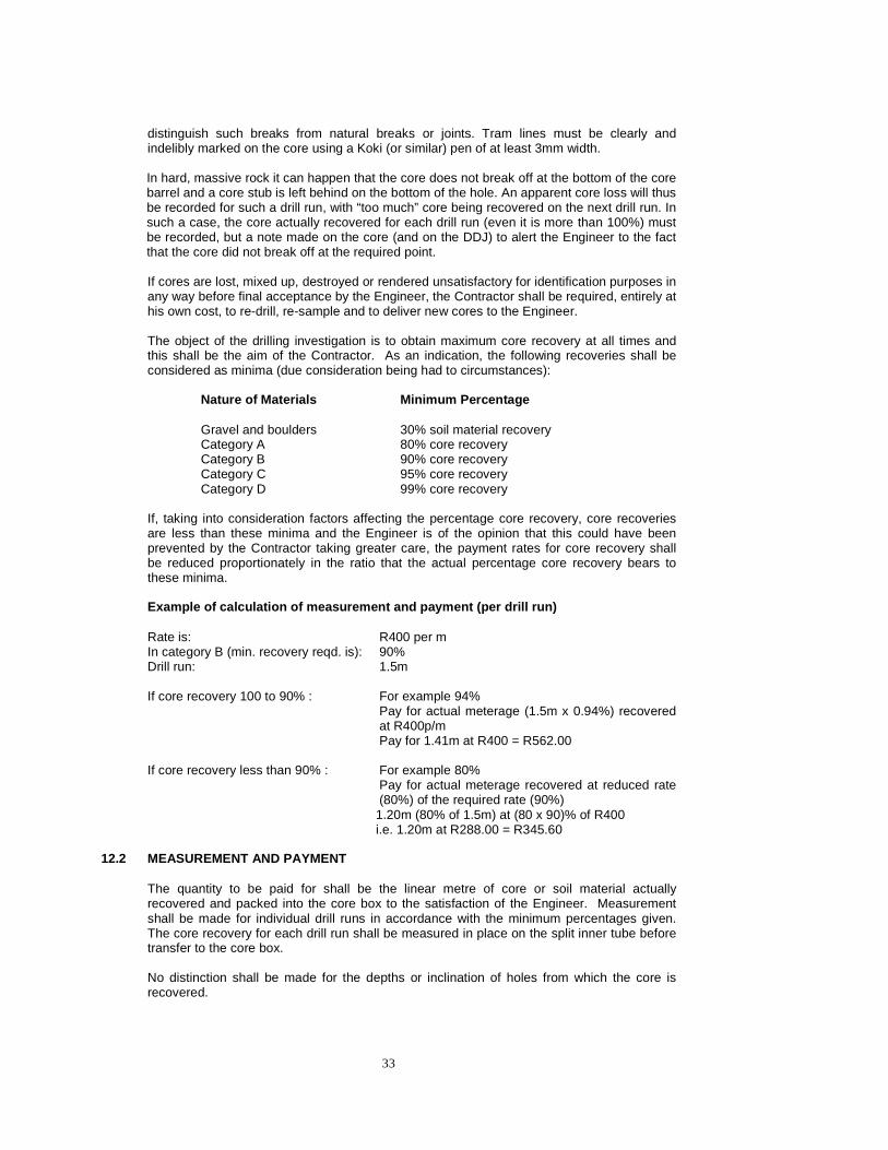
33
distinguish such breaks from natural breaks or joints. Tram lines must be clearly and indelibly marked on the core using a Koki (or similar) pen of at least 3mm width. In hard, massive rock it can happen that the core does not break off at the bottom of the core barrel and a core stub is left behind on the bottom of the hole. An apparent core loss will thus be recorded for such a drill run, with “too much” core being recovered on the next drill run. In such a case, the core actually recovered for each drill run (even it is more than 100%) must be recorded, but a note made on the core (and on the DDJ) to alert the Engineer to the fact that the core did not break off at the required point. If cores are lost, mixed up, destroyed or rendered unsatisfactory for identification purposes in any way before final acceptance by the Engineer, the Contractor shall be required, entirely at his own cost, to re-drill, re-sample and to deliver new cores to the Engineer. The object of the drilling investigation is to obtain maximum core recovery at all times and this shall be the aim of the Contractor. As an indication, the following recoveries shall be considered as minima (due consideration being had to circumstances):
Nature of Materials
Minimum Percentage
Gravel and boulders 30% soil material recovery Category A 80% core recovery Category B 90% core recovery Category C 95% core recovery Category D 99% core recovery
If, taking into consideration factors affecting the percentage core recovery, core recoveries are less than these minima and the Engineer is of the opinion that this could have been prevented by the Contractor taking greater care, the payment rates for core recovery shall be reduced proportionately in the ratio that the actual percentage core recovery bears to these minima. Example of calculation of measurement and payment ( per drill run)
Rate is: R400 per m In category B (min. recovery reqd. is): 90% Drill run: 1.5m If core recovery 100 to 90% : For example 94%
Pay for actual meterage (1.5m x 0.94%) recovered at R400p/m
Pay for 1.41m at R400 = R562.00 If core recovery less than 90% : For example 80%
Pay for actual meterage recovered at reduced rate (80%) of the required rate (90%) 1.20m (80% of 1.5m) at (80 x 90)% of R400 i.e. 1.20m at R288.00 = R345.60
12.2 MEASUREMENT AND PAYMENT
The quantity to be paid for shall be the linear metre of core or soil material actually recovered and packed into the core box to the satisfaction of the Engineer. Measurement shall be made for individual drill runs in accordance with the minimum percentages given. The core recovery for each drill run shall be measured in place on the split inner tube before transfer to the core box. No distinction shall be made for the depths or inclination of holes from which the core is recovered.
34
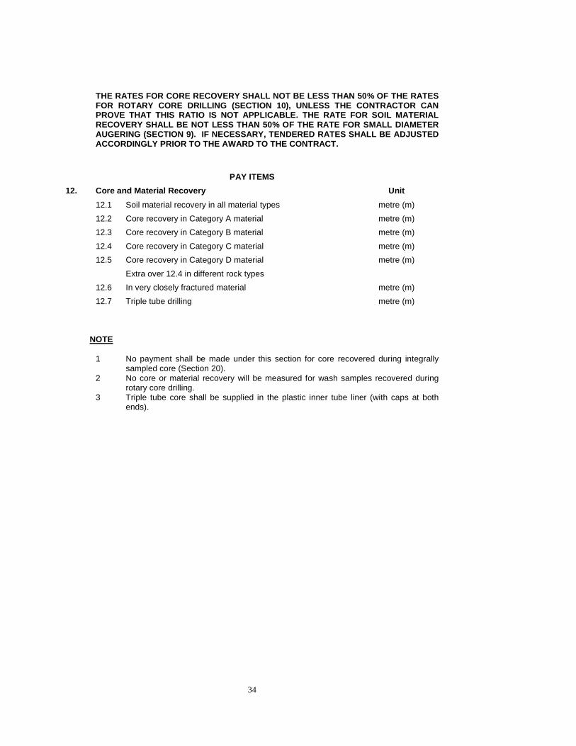
THE RATES FOR CORE RECOVERY SHALL NOT BE LESS THAN 50% OF THE RATES FOR ROTARY CORE DRILLING (SECTION 10), UNLESS THE CONTRACTOR CAN PROVE THAT THIS RATIO IS NOT APPLICABLE. THE RATE F OR SOIL MATERIAL RECOVERY SHALL BE NOT LESS THAN 50% OF THE RATE FOR SMALL DIAMETER AUGERING (SECTION 9). IF NECESSARY, TENDERED RATES SHALL BE ADJUSTED ACCORDINGLY PRIOR TO THE AWARD TO THE CONTRACT.
PAY ITEMS
12. Core and Material Recovery Unit
12.1 Soil material recovery in all material types metre (m)
12.2 Core recovery in Category A material metre (m)
12.3 Core recovery in Category B material metre (m)
12.4 Core recovery in Category C material metre (m)
12.5 Core recovery in Category D material metre (m)
Extra over 12.4 in different rock types
12.6 In very closely fractured material metre (m)
12.7 Triple tube drilling metre (m)
NOTE 1 No payment shall be made under this section for core recovered during integrally
sampled core (Section 20). 2 No core or material recovery will be measured for wash samples recovered during
rotary core drilling. 3 Triple tube core shall be supplied in the plastic inner tube liner (with caps at both
ends).

35
SECTION 13 CASING 13.1 DESCRIPTION
This section relates to the installation, irrespective of the method employed, of casings necessary for the drilling of boreholes and the removal or leaving in the hole thereof, as instructed by the Engineer. On completion of drilling at each hole, the Engineer shall notify the Contractor whether the casing, if any, is to be left in the hole. If casing is irrecoverably jammed in any borehole the Engineer may, at his discretion, pay for any casing so lost. The Engineer’s decision shall be based on: (a) Whether every reasonable attempt has been made by the Contractor to extract part
or all of the casing (b) That the Contractor took every reasonable precaution during drilling to ensure that
the casing would not become jammed (for example, rotating the casing every morning to ensure its freedom, the use of drilling aids and maintaining water return).
Whether casing is left in the borehole or not, the Contractor shall comply with the requirements as set out in Section 35. The Contractor shall supply detail, in his Daily Drilling Journal (DDJ), of any casing installed, left permanently or jammed in a hole.
13.2 MEASUREMENT AND PAYMENT
The quantity to be paid for shall be the linear metre of casing actually installed and/or subsequently removed or on instruction of the Engineer, left permanently in the hole, or casing irrecoverably jammed in the hole (for which the Engineer has agreed to pay), measured from the casing reference height. Unless depth increments are detailed in the Bill of Quantities, payment shall be irrespective of depth. For the purposes of measurement, the length of casing installed shall be measured relative to a casing reference level as follows: (a) For dry holes. From the mean adjacent ground level (b) For wet holes. From 0.5m above the highest normal water level or such height
necessary to protrude through the drilling barge or platform Casing in category B or harder material, in boulders or gravel shall be measured per linear metre and paid extra over the rate for removable casing. Where casing has already been installed and a reduction in the size of the casing is required for further advance, no payment shall be made for the portion(s) of the smaller diameter casing(s) contained within the larger diameter casing. No extra payment shall be made for the use of drilling fluids or muds for the installation of casing unless agreed to and approved by the Engineer. Casing in inclined holes (see Section 10) shall be an extra over payment per metre of casing installed, regardless of size.
36
PAY ITEMS
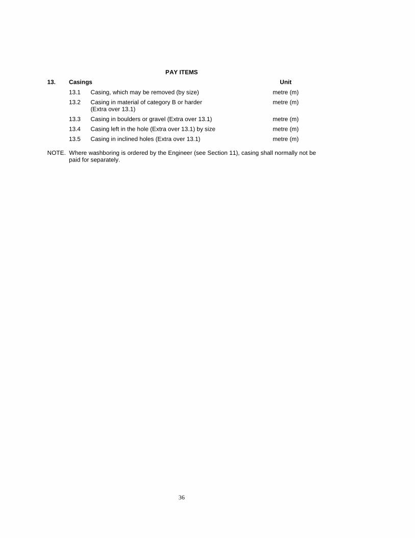
13. Casings Unit
13.1 Casing, which may be removed (by size) metre (m)
13.2 Casing in material of category B or harder (Extra over 13.1)
metre (m)
13.3 Casing in boulders or gravel (Extra over 13.1) metre (m)
13.4 Casing left in the hole (Extra over 13.1) by size metre (m)
13.5 Casing in inclined holes (Extra over 13.1) metre (m) NOTE. Where washboring is ordered by the Engineer (see Section 11), casing shall normally not be
paid for separately.

37
SECTION 14 THE USE OF DRILLING AIDS 14.1 DESCRIPTION
This section relates to the use of drilling aids such as mud or fluid to facilitate drilling. The intention of the contract is at all times to optimise core recovery and it is therefore required, as standard practice, that the Contractor employs such drilling aids as are necessary to achieve this and these will not be paid for. The Contractor shall select the type of drilling aid used for the particular circumstance when instructed to use them by the Engineer. Only biodegradable drilling aids shall be employed. The Contractor is required to produce documentary proof of this fact prior to commencing any drilling. The use of drilling aids in any borehole shall specifically be noted on the Daily Drilling Journal (DDJ). Drilling aids shall be properly disposed of after use, to the satisfaction of the Engineer, and it shall not at any time be discharged into any watercourse, drain or place in which it may cause pollution or contamination.
14.2 MEASUREMENT AND PAYMENT
The purpose for which a drilling aid is employed shall dictate the measurement and payment therefore. (i) To improve bit life, reduce friction, aid in removal of cutting and facilitate core
recovery. This is considered to be to the contractor’s advantage and shall not be measured and paid for.
(ii) If instructed or agreed to by the Engineer to be used in lieu of casing to keep a hole
open. This shall be measured and paid for per linear metre of hole drilled using this method.
(iii) All other circumstances shall be considered exceptional and the Engineer shall pay
for the actual purchase price of the mud which shall be measured and paid for under a provisional sum. The quantity of drilling aid to be paid for shall be the nett cost of the drilling aid used in the drilling of the hole, plus a mark-up for handling and profit. Transport, labour, equipment and any other costs for the installation of the drilling aid shall be deemed to be included in the Contractor’s mark-up for handling and profit. Reimbursement for the cost will be made only after the Contractor has provided to the Engineer acceptable proof of payment to the supplier. When considering such a case, the following shall be taken into consideration:
(a) the objective of achieving maximum core recovery (b) that no other technique would have the desired result
(c) the uniqueness of the conditions prevailing
Examples of circumstances which might be considered exceptional:
• The presence of artesian water requiring the use of heavy muds • Complete loss of drilling water at depth where sealing of the hole with
casing or by stabilisation grouting (see Section 15) is not practical, and where loss of water circulation might result in loss of the hole
• The installation of casing in thick sands where, unless mud is used, the casing could jam.

38
PAY ITEMS
14. Drilling aids Unit
14.1 Use in lieu of casing metre (m)
14.2 Purchase price of drilling aids provisional sum (P sum)
14.3 Mark-up for handling and profit percent (%)

39
SECTION 15 STABILISATION GROUTING 15.1 DESCRIPTION
Grouting for the stabilisation of fractured or brecciated zones or boulders encountered, or in other situations as agreed to by the Engineer, may be undertaken with the approval of the Engineer. The grout employed shall usually be cement but the type of grout to be employed shall be decided upon by the Contractor with due regard to the circumstances. Only such grouting as ordered or approved by the Engineer shall be measured for payment. Whenever possible, grouting shall be arranged to take place at the end of a working day so that it may set overnight and be drilled out the next morning. If this is not possible, and is agreed to by the Engineer, Standing Time shall be payable in accordance with Section 37, but only in the event that it exceeds two hours in these particular circumstances.
Where grout is cored out, this shall be placed into the core box in the position from which it
was drilled out, as a record of the grouting carried out. 15.2 MEASUREMENT AND PAYMENT
The quantity to be paid for shall be the actual quantity of grout employed (measured in 50kg bags) and the length of hole (measured in linear metres) requiring to be grouted. No payment shall be made for drilling out of grout and this cost must be included in the other rates.
PAY ITEMS
15. Stabilisation grouting Unit
15.1 Supply of grout bag
15.2 Installation of grout metre (m)
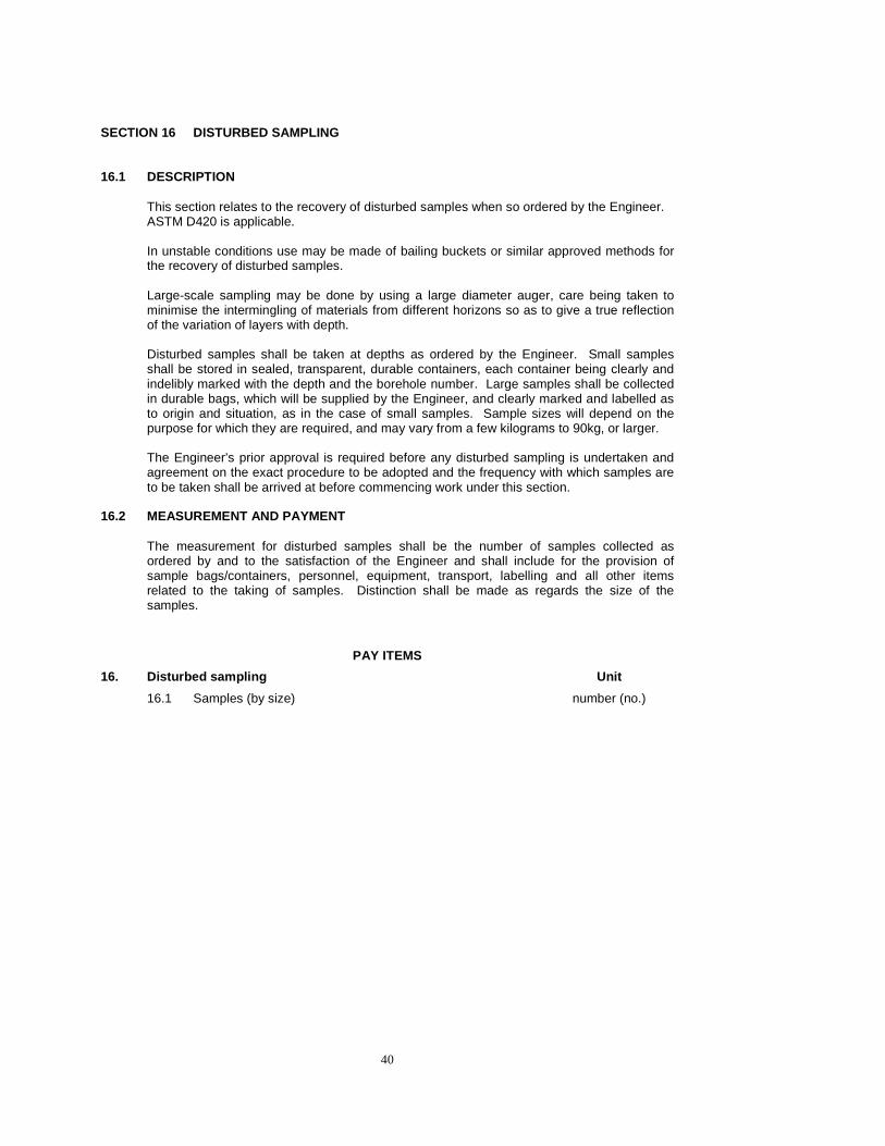
40
SECTION 16 DISTURBED SAMPLING 16.1 DESCRIPTION
This section relates to the recovery of disturbed samples when so ordered by the Engineer. ASTM D420 is applicable. In unstable conditions use may be made of bailing buckets or similar approved methods for the recovery of disturbed samples. Large-scale sampling may be done by using a large diameter auger, care being taken to minimise the intermingling of materials from different horizons so as to give a true reflection of the variation of layers with depth. Disturbed samples shall be taken at depths as ordered by the Engineer. Small samples shall be stored in sealed, transparent, durable containers, each container being clearly and indelibly marked with the depth and the borehole number. Large samples shall be collected in durable bags, which will be supplied by the Engineer, and clearly marked and labelled as to origin and situation, as in the case of small samples. Sample sizes will depend on the purpose for which they are required, and may vary from a few kilograms to 90kg, or larger. The Engineer’s prior approval is required before any disturbed sampling is undertaken and agreement on the exact procedure to be adopted and the frequency with which samples are to be taken shall be arrived at before commencing work under this section.
16.2 MEASUREMENT AND PAYMENT
The measurement for disturbed samples shall be the number of samples collected as ordered by and to the satisfaction of the Engineer and shall include for the provision of sample bags/containers, personnel, equipment, transport, labelling and all other items related to the taking of samples. Distinction shall be made as regards the size of the samples.
PAY ITEMS
16. Disturbed sampling Unit
16.1 Samples (by size) number (no.)

41
SECTION 17 UNDISTURBED SAMPLING 17.1 DESCRIPTION 17.1.1 Thin-walled tube samples
Undisturbed sampling shall be carried out in accordance with the “American Society for Testing and Materials” (ASTM) test method D1587. The Engineer may order undisturbed sampling using thin walled tubes while the investigation is in process. Sampling shall be carried out either by means of a thin walled sampling tube of generally not less than 63mm internal diameter (ie. to fit inside N size casing), or as may be specified in the Bill of Quantities or as ordered by the Engineer. The depths at which samples shall be taken in a borehole shall be as determined by the Engineer. All sampling tubes shall be of 16 or 18 gauge stainless steel, rust free and be coated with a thin layer of lacquer to prevent rusting. All tubes employed shall have machine-prepared, sharp cutting edges and shall be able to accommodate a minimum of 600mm of sample, to the satisfaction of the Engineer. Prior to commencing any undisturbed sampling, the Contractor shall submit to the Engineer for his approval, a sample tube to be employed as a reference standard. Once approved by the Engineer, he shall retain this reference tube until completion of the contract and all sampling tubes employed on the contract shall be judged against this reference standard. Samples shall be supplied in the sampling tube. Before the samples are waxed up with microcrystalline wax as described in ASTM D1587, the top end shall be inspected to determine whether in fact a sufficiently acceptable length of undisturbed sample has been obtained. Should, in the opinion of the Engineer, too great a length of disturbed cuttings or sludge be present in the tube, the sample shall then be discarded and a new sample shall be taken. All samples shall be sealed and packed in such a way as to be able to resist damage during normal handling and transport. The minimum length of sample is usually 300mm of undisturbed material, but conditions may be such that it is not possible to recover this amount of sample. The Engineer may order that piston sampling be carried out in such materials as cannot successfully be sampled by means of conventional thin wall sampling. The equipment to be employed shall comprise a sampling tube as above with an inner piston fitted with a least two rubber sealing rings set into the piston. The length of the piston shall be not less than twice the diameter of the sample tube and shall be fitted on a small diameter inner rod which passes through the head of the sampling tube and thence to surface through the inside of the rods on which the sampler is mounted. Prior to undertaking piston sampling the Contractor shall provide the Engineer with a detailed method statement and provide the sampler for inspection by the Engineer. The piston sampler shall be advanced to the bottom of the hole or drill rods with the piston at the bottom edge of the sampling tube and the inner rods protruding up through the bore of the drill rods. The inner rod shall then be held stationary, by clamping to the drill rig, while the sampling tube is advanced past the stationary piston. Once the sampling tube is fully advanced (determined by measurement), the inner rod shall be clamped relative to the drill rods and the whole assembly withdrawn without rotation or disturbance. If at all possible the assembly shall be withdrawn entirely without uncoupling drill rods. If this is not possible, extreme care shall be taken when uncoupling the drill rods to ensure that no relative movement takes place between the inner and drill rods. Samples shall be clearly marked on an aluminium, or similar rustproof material, tag which is tied to the tube with the Contractor’s name, borehole number, sample length, the orientation of the sample (i.e. which end is up), contract number, the depth at which it was recovered and the date on which the sample was taken. As a general rule, it is not possible to carry out thin wall sampling in material where the SPT “N” value exceeds 20 and the Contractor shall be the sole judge of whether or not it is feasible to take a sample without damage to the sample tube. Should the Engineer

42
nevertheless instruct the Contractor to proceed with sampling, this will be measured whether or not a sample is recovered and the Engineer shall pay for the replacement or repair cost if the tube were damaged.
17.1.2 Block samples
When so ordered by the Engineer, the Contractor shall recover undisturbed block samples from the sides of trenches or large diameter auger holes. The block samples shall be cut in accordance with BS5930, section 19 and shall ideally be 300 x 300 x 300mm. After careful removal from its in-situ position, it shall immediately carefully and completely be wrapped in clingfilm (at least 3 layers) to ensure that it remains intact and the moisture content of the sample remains constant. A label (clearly and indelibly marked) shall be inserted under the outermost layer of film so that it can be read from the outside. The label shall indicate the depth of sample, test pit/auger hole number and the orientation of the sample (ie which side of the sample is “up”). Samples shall be delivered to the Engineer as soon as possible after extraction for safekeeping. The Engineer shall advise where the samples are to be delivered to.
17.2 MEASUREMENT AND PAYMENT
The quantity to be measured shall be the number of samples recovered to the satisfaction of the Engineer and shall include for all items necessary to extract, protect and maintain the sample in an undisturbed condition Sampling tubes remain the Contractor’s property and the Engineer must return these to him within 6 weeks of practical completion of the work (see Section 39), in the same condition in which they were received. The Engineer shall replace (or pay the replacement cost to the Contractor) for any damaged or retained tubes. The Contractor shall advise the Engineer one week before the expiry of the 6 weeks deadline that he requires the tubes to be returned. The Engineer is required to return the tubes within one week after receiving such notification. Should the Engineer fail to return the tubes within the stipulated period, he shall return them either when he becomes aware that he has them, or within one week of receiving notification from the Contractor to this effect.
PAY ITEMS
17. Undisturbed sampling Unit
17.1 Thin walled tube samples number (no.)
17.2 Piston samples number (no.)
17.3 Block samples number (no.)

43
SECTION 18 BOREHOLE ORIENTATION SURVEYS 18.1 DESCRIPTION
“Down-the-hole” inclination and direction surveys of certain drill holes may be ordered by the Engineer while the investigation is in progress using suitable instruments approved by the Engineer. The survey interval within any particular drill hole shall be determined by the Engineer, but shall normally be carried out at intervals not exceeding 100m in vertical holes and at intervals between 20 and 30m in all inclined holes. The inclination and direction angles are to be determined to within an accuracy of 0.5º and may be required to be measured and recorded at least twice at each ordered survey point within the drill hole. When the Engineer orders this work, the Contractor shall provide, for the Engineer’s approval, full details of the type of instrument he intends using and a detailed method statement setting out how he will undertake these surveys. The Engineer reserves the right to withdraw his approval of any such instrument if, in his opinion, the results are not consistent and satisfactory and the Contractor shall then, at his own cost, arrange for the provision on site of acceptable alternative equipment.
18.2 MEASUREMENT AND PAYMENT
The establishment and provision on site and conducting of surveys shall be paid under a provisional sum. Reimbursement of the cost will only be made after provision of acceptable proof of payment to the supplier by the Contractor is provided to the Engineer.
PAY ITEMS
18. Borehole orientation surveys Unit
18.1 Provision of equipment and surveying provisional sum (P sum)
18.2 Mark up for handling and profit percent (%)

44
SECTION 19 CORE ORIENTATION SURVEYS 19.1 DESCRIPTION
Core orientation surveys may be ordered by the Engineer while drilling is in progress and shall be carried out using approved methods. Distinction, as given in the Project Specifications, shall be made between the depths at which surveys may be required. Surveys may be required in vertical holes. Each core orientation shall be carried out in conjunction with a direction and inclination survey as described in Section 18 (if so ordered by the Engineer). As part of these surveys (if required in the Project Specifications), the Contractor may be required to extend the orientation of the core upwards and downwards from a section of orientated core. This shall be done by fitting the core pieces together, marking the core by means of an oriented reference line and packing the core into the core box with the reference line uppermost on the core. The extension of the orientation shall be extended as far as possible upwards and downwards, or as ordered by the Engineer. In order to prevent movement of the core, it may be required that the core be cushioned with bubble wrap as detailed in Section 31. Prior to undertaking any surveys, the Contractor shall provide the Engineer with a detailed method statement and provide the equipment for inspection by the Engineer.
19.2 MEASUREMENT AND PAYMENT
The quantity to be paid for shall be the number of surveys as ordered by the Engineer and carried out to his satisfaction.
PAY ITEMS
19. Core orientation surveys Unit
19.1 Core orientation surveys number (no.) NOTE: Establishment of the equipment on site shall be measured under Section 3 only when ordered by the Engineer.
45
SECTION 20 ORIENTATED INTEGRAL CORE 20.1 DESCRIPTION
This section relates to the recovery of Orientated Integral Core (OIC) from such boreholes and depths as may be required and instructed by the Engineer. Prior to commencing any core orientations, the Contractor shall provide details of the equipment to be used and a detailed method statement for the process. OIC sampling entails the accurate placing into rock (with a suitable grout) of an orientated small bore pipe which is overcored and recovered once the grout has set. Typically the method that may be employed is: (i) Drill to depth required
(ii) Drill with cone shaped or bullnose bit to provide a tapered (funnel) section at the
bottom of the hole
(iii) Drill a pilot hole (E size or similar) to 1.5m below the bottom of the hole using appropriately sized bushes to ensure that the hole is drilled centrally in the borehole
(iv) Grout in an orientated grout pipe. The grout employed shall be selected by the
Contractor with due regard to the circumstances.
(v) Over-core the grout pipe once the grout has set
Due care shall be taken to ensure that the pilot hole is drilled straight, centrally in the hole and is well flushed to clear it of cuttings. It is preferable that over-coring be carried out using at least TNW size as this provides a larger diameter core than conventional NXM size. In certain instances it may be necessary, on the Engineer’s instructions and only if all previous attempts using unpressured grout have been unsuccessful, to pressure grout the core to ensure a satisfactory sample. The Contractor shall make provision for such pressure grouting if required. The orientation of the grout pipe shall be known to an accuracy of 1°. The measurement of the orientation shall be by means of a compass or other approved method and shall be reported to the Engineer and recorded on the DDJ. In addition, two reference pegs 5 and 15m from the borehole (10mm diameter steel pegs set in 200 x 200 x 200mm concrete), shall be set out in the orientation of the grout pipe, for subsequent surveying in. The timing of the grouting of the core shall be arranged in such a way that, circumstances permitting, it shall take place at the end of a day’s work. Drilling out of the core may then commence on the following morning if the grout has set sufficiently. Should it not be possible to arrange this, the provisions of Section 37 shall apply in respect of the drilling rig and crew, for any time lost during normal working hours.
If ordered by the Engineer, the orientation of the core may be required to be extended upwards and downwards by the same process as given in Section 19.

46
20.2 MEASUREMENT AND PAYMENT
The quantity to be paid for shall be per linear metre of OIC recovered to the Engineer’s satisfaction. The grouting carried out shall not be measured under Section 15 and the cost thereof shall be included in the rates for this work. Any core recovered under this item will not be measured under Section 12.
PAY ITEMS
20. Orientated integral core Unit
20.1 Orientated core metre (m) NOTE: Standing time relating to this work shall be measured and paid according to Section 37 , if applicable
47
SECTION 21 DOWN THE HOLE PHOTOGRAPHY 21.1 DESCRIPTION
If ordered by the Engineer, in cases where insufficient data is available from the recovered core, a photographic or video recording is to be made by means of down-the-hole equipment. The equipment and method of photography shall be to the satisfaction of the Engineer and as provided for in the Project Specifications. Permanent records of the work on colour filmstrip, videotape or digitally stored must be produced by the Contractor and will be retained by the Engineer. In the case of ordinary borehole photography the Contractor shall supply the Engineer with the negatives and two prints of each photograph. In the case of video recording only one copy of the videotape is to be supplied. Digital data shall be supplied on CD in jpeg format (or other format which can easily be viewed using “normal” and not highly sophisticated software).
The Contractor shall ascertain at tender stage, from the specialist providing this service, the exact minimum borehole diameter required to deploy the down-the-hole borehole photographic equipment (video, digital or other borehole camera) and shall ensure that the equipment will fit into the diameter of holes to be drilled on the contract. A list of possible service providers is provided in the Project Specifications. A short method statement and quotation for this work regarding the proposed equipment, methods, cable lengths, hourly rates for the equipment and personnel shall be provided with the tender.
21.2 MEASUREMENT AND PAYMENT
The provision of this equipment and the photography shall be paid under a Prime Cost Sum. Payment against the Prime Cost Sum shall be as follows: a) The amount actually paid by the Contractor to the service provider in the execution of
the Engineer’s written instruction; b) Plus a percentage mark up for handling and profit. The Contractor shall not be entitled to any further payments or to a fee, commission, rebate, discount or similar payment or consideration from the service provider and shall disclose and subtract such amounts from the amount claimed in a) above. Payment shall be made only after production by the Contractor of proof of payment to the supplier.
PAY ITEMS
21. Down the hole photography Unit
21.1 Provision for down-the-hole photography service provider prime cost sum (PC sum)
21.2 Mark up for handling and profit percent (%)

48
SECTION 22 VANE SHEAR TESTING 22.1 DESCRIPTION
The in-situ shear strength of materials may be determined by means of a vane shear apparatus complying with the American Society for Testing and Materials (ASTM) Designation D2573. The apparatus shall consist of a stainless steel cruciform of which the length is twice the overall blade width as ordered by the Engineer. The Engineer shall indicate in the Project Specifications the range of vane sizes which he requires to be provided on site. At each testing position the dimensions of the vane(s) to be employed shall be agreed with the Engineer. The torque shall be applied by means of a standard calibrated torque wrench or similar equipment. A current certificate of calibration from a source approved by the Engineer shall be supplied to the Engineer before any testing is commenced. The torque wrench shall be designed to give minimum backlash and shall be capable of producing a minimum torque of 700Nm. The vane rod shall be completely enclosed in a sleeve suitably designed to exclude soil particles and the effects of soil adhesion throughout the length it penetrates the soil. The sleeve shall commence just above the blades at a distance of approximately twice the diameter of the rod. The rods connecting the vane to the torque instrument shall be sufficiently strong to withstand axial thrust and yet be flexible. Bearings used to locate the rod centrally within the borehole shall be fitted to the rods as the system is lowered down the hole. The apparatus shall be checked before each usage. Procedure
(a) The bottom of the hole shall be cleaned out and all loose and disturbed material removed.
(b) The vane together with the connecting rods and bearings shall be lowered down the borehole, which will normally be cased. Rod couplings should remain tight during the lowering procedure. The spacing of the bearings is dependent on the rigidity of the rods, and should normally be between 3 and 7m centres.
(c) With the vane resting on the undisturbed soil at the bottom of the borehole, and the rods centrally located, the vane shall be steadily pressed, without twisting, into the soil to a depth of approximately four diameters of the borehole.
(d) The torque wrench shall then be connected to the rods and a torque applied to shear the soil. The torque reading at point of shear shall be noted. The rate of application of torque should be such as to produce a rotation of the rods of approximately 6º per minute, or as directed by the Engineer.
(e) Once shear has been achieved the rods shall be rapidly rotated and the residual shear torque reading noted. The residual value shall be taken as that recorded after the vane has been rotated through 10 revolutions.
(f) Recording Test Results The results of the vane shear tests shall be recorded in a suitable format as approved by the Engineer, and shall include the following information: (i) date of test (ii) location and depth of test, borehole number (iii) type of vane shear apparatus (size and shape of vane) (iv) torque at point of shear (v) residual shear torque reading (vi) rate of application of torque (vii) time required to achieve shear

49
22.2 MEASUREMENT AND PAYMENT
Vane shear tests will be measured by number for tests carried out on the instruction of and to the satisfaction of the Engineer and for setting up at each borehole. Distinction will be drawn between tests at less than and greater than 15m depth. Establishment of the equipment on site shall be measured as a Lump Sum when ordered by the Engineer and shall include for the cost of de-establishment on completion of the work.
PAY ITEMS
22. Vane shear tests Unit
22.1 Establishment of equipment on site lump sum (sum)
22.2 Setting up at each borehole number (no.)
22.3 Tests number (no.)

50
SECTION 23 STANDARD PENETRATION TEST 23.1 DESCRIPTION
Standard penetration tests (SPT) shall be carried out in accordance with the international reference test procedure laid down in the proceedings of the First International Symposium on Penetration Testing (ISOPT-1) 1988 except that the number of blows for each 75mm of the total 450mm penetration shall be recorded. Prior to any SPTs being carried out, the Engineer shall inspect and approve the equipment to be used. Before commencing the test, the borehole shall be cleaned to the depth where the testing is to be done. Care must be taken to prevent disturbance of the material to be sampled. The washing out of the hole by means of side discharge bits is allowable, but not by means of washing through an open tube. Care shall be taken to ensure that the borehole is cleaned right to the bottom of the hole in all circumstances. Where casings are used, the bottom end of the casing shall be no closer than 150mm to the level where the tests are commenced. When drilling in sand or silt below the water table, the water level in the casing shall always be kept higher than the ground water level, so that sand and silt is kept from flowing into the borehole. A valid SPT cannot be executed where an influx of sand or silt has occurred, since such influx disturbs the materials under the base height of the casing, as well as causing greater friction against the sample tube. When boring under the said conditions, water shall be continuously added in order to maintain the water level in the casing level with the top of the casing. Steady water supply is extremely important during the removal of the drilling rods since a drop in level of the water in the hole accompanies removal. The rods must be removed slowly and gradually. Samples recovered from the split barrel sampler shall be sealed in an approved, airtight, transparent container and placed in the core box at the relevant depth and the blow counts written onto the sample container. Where site conditions are such or the Engineer orders this, SPTs may be taken one after the other in order to provide a “continuous” sample. When it becomes evident that, due to the presence of gravel or pebble layers, SPT tests cannot be performed with the standard split barrel sampler, the driving shoe and the standard split barrel sampler shall be replaced with a 60º cone-end shoe and a normal tube barrel, the overall dimensions of which correspond to that of the standard split barrel sampler. The outside diameter of the cone-end shoe shall be 51mm and the total length from tip to base shall be 56mm. The test with the cone-end shoe shall in all other respects be executed in accordance with ISOPT standards except that the number of blows for each 75mm of the total 450mm penetration shall be recorded. Care shall be taken to ensure that the energy of the hammer is not reduced by friction between hammer and wall or by any other cause. “Refusal” of the SPT is defined as when the number of blows necessary to penetrate 75mm exceeds 25. If refusal occurs, the blow counts recorded till refusal and the actual penetration in mm for the last (refusal) cycle shall be recorded. The rods used during SPT tests shall have a stiffness of not less than that of type AW rods (43.7mm OD, 34.1mm ID, 6kg/m) or BW rods (54.0mm OD, 44.4mm ID, 8kg/m). Bearings (or steadies) shall be provided at 3m centres.
51
23.2 MEASUREMENT AND PAYMENT
The quantity to be paid for shall be each SPT as ordered by the Engineer and carried out to his satisfaction. Where the depth at which the test is required exceeds 50m, depth increments (if any) as detailed in the Project Specifications and the Bill of Quantities, shall apply.
PAY ITEMS
23. Standard penetration test Unit
23.1 SPTs number (no.) NOTE: Establishment of this equipment shall not be measured separately and the Contractor shall allow for this under the relevant rates in Section 3 .

52
SECTION 24 DYNAMIC PROBING (SUPER HEAVY) 24.1 DESCRIPTION
Dynamic Probing (Super Heavy) (DPSH) sounding shall be carried out exactly like SPT sounding except that a sacrificial cone is to be used in place of the sampling tube and shoe. The cone shall have the same dimensions as the solid cone referred to in Section 23, but shall have a stub to fit loosely into the drill rod onto which it is mounted. When the drill rod is withdrawn after the final sounding, the cone will slip out of the rod and remain in the hole. Blow counts are to be recorded for each 300mm penetrated and continue until refusal, or the required depth is reached, whichever is the shallower. On completion of the sounding, the rods shall be withdrawn by 600mm and then redriven to provide a measure of the friction on the rods. Blows may be imparted using either a continuous hammer or a snatch block arrangement, provided that the height of the fall of the hammer is accurately controlled. Results shall be provided in an Excell spreadsheet of depth (in 300mm increments) versus blow count. 24.2 MEASUREMENT AND PAYMENT
Setups of the rig shall be measured by number and shall include transport, personnel, equipment and all costs necessary to set up the rig at each testing position. DPSH soundings shall be measured per metre as ordered by the Engineer and carried out to his satisfaction and shall include the provision of results. Where the depth at which the test is required exceeds 50m, depth increments (if any) as detailed in the Project Specifications and the Bill of Quantities, shall apply.
PAY ITEMS
24. Dynamic Probing (Super Heavy) Unit
24.1 Setup at each position
24.2 DPSH
number (no.)
metre (m)
NOTE: Establishment of this equipment on site, when ordered by the Engineer, shall be measured under Section 3 .

53
SECTION 25 CONE PENETRATION TEST 25.1 DESCRIPTION
The cone penetration test (CPT) or Dutch probing is carried out to determine the nature of soft materials and shall be carried out by a specialist sub-contractor. Only apparatus conforming to the international reference test procedure laid down in the proceedings of the First International Symposium on Penetration Testing (ISOPT-1), 1988 and approved by the Engineer shall be acceptable. The type (mechanical or electrical) and sensitivity of the cones to be used shall be detailed in the Project Specifications. An operator who is familiar with the standard procedures shall carry out the tests. In particular the following shall be applicable: (a) The equipment shall be capable of exerting a thrust of at least 100 kN (b) The rate of penetration of the equipment shall be 20 ± 5mm/sec
(c) The machine shall preferably have a minimum stroke of 1m
(d) The precision of measurements made shall not be worse than the larger of the
following values:
a. 5% of the measured value b. 1% of the maximum value to the range
(e) The pressures recorded shall be of the load cell/measuring device connected to the
cone and not of the jacking system. (f) Depth measurements shall be accurate to at least 100mm
When the Engineer orders this work, the Contractor shall provide full details of the specialist subcontractor (equipment, operator and experience) whom he intends employing to undertake this work. The Engineer reserves the right to withdraw his approval of the subcontractor if, in his opinion, the results are not consistent and satisfactory. In this case another subcontractor shall be sought.
25.2 PROBING
Refusal of the equipment shall be taken as a total force of 100kN or a consistent cone resistance of 30MPa. Ground conditions may however be such (e.g. boulders present, friction build up on the rods so great that there is a danger of the rods becoming stuck in the hole, etc) that it may be necessary to cease probing before the refusal values stated are attained. The insertion of a friction reducer may reduce the total friction on the rods and allow probing to proceed. The friction reducer shall not be closer than 1m to the base of the cone. The maximum depth to which probing is to be carried out shall be given in the Project Specifications.
25.3 ANCHORING
Anchoring of the CPT rig is usually by means of screw auger anchors, which are screwed into the ground to provide a reaction to the thrust of the rig. Where ground conditions are such that it is not possible to screw in the anchors, the necessary reaction may be provided by means of grouted earth anchors, kentledge or other techniques as approved by the Engineer. Whatever anchoring technique is employed it shall be capable of resisting an up-thrust of 100kN.
54
25.4 PROBING IN PRE-DRILLED HOLES OR OVER WATER
Where material which cannot be probed (boulders, ferricrete, etc) occurs overlying soft material, pre-drilling or augering through the hard material may be carried out. Casing (maximum B size) shall be installed in the predrilled hole and probing shall then be carried out from the bottom of the hole. Due care shall be taken that no obstructions occur at the end of the casing. This is particularly applicable when casing has been advanced through boulders. The casing shall not protrude more than 200mm above the ground level. Where probing is carried out in water, casing as specified shall be installed to the bottom to prevent flexing of the rods. Whenever possible the rig shall be anchored to the bottom and only in water deeper than 3m may the probe rig be anchored to the barge or drilling platform only. In the latter case the barge / platform shall itself be securely anchored to the bottom to provide the necessary reaction and to ensure that vertical and horizontal movements of the barge / platform are kept to an absolute minimum. In tidal waters it may necessary to programme the works so that probing is carried out either during neap tide or at the change of the tides to minimise vertical movements during probing.
25.5 TESTING
(a) Mechanical probing
The penetration tip shall comprise a cone and friction sleeve, which can be advanced independently to provide readings of cone and cone-plus-sleeve resistances. Readings shall be taken at a vertical spacing of 200mm.
(b) Electrical probing
Readings of resistances shall be continuous. Probing using a piezocone probe with dissipation tests may be carried out to determine the material type and permeability. Dissipation tests shall be carried out by stopping penetration of the equipment and recording the time taken for the pore pressure to stabilise. The test shall continue until an effectively constant pore pressure reading has been recorded for 5 minutes, or until the measured pore pressure returns to the hydrostatic value, or as ordered by the Engineer.
25.6 REPORTING OF RESULTS
Results shall be recorded on site in such a way that direct access to the data is available (e.g. either by written or chart records for mechanical probing and by continuous chart records for electrical probing); exclusive recording of test results onto magnetic tape or computer shall not be permitted. All supplied data shall include calibration data. The results shall be reported as follows: (a) Mechanical probing
i. Values read from gauges or recorded on chart recorder shall be supplied to the
Engineer.
ii. Cone resistance and friction ratio shall be plotted (200mm interval readings) on a combined graph for each hole to the scales specified in the standards.
(b) Electrical probing
(i) As for (a) (i) above
(ii) Cone resistance and friction ratio or cone resistance and pore pressure shall
be plotted continuously to the same scale as (a) (ii) above
55
(iii) Any dissipation tests carried out shall be plotted on a graph to a suitable scale of pore pressure versus time. Each dissipation shall be plotted separately and record the hole number, depth of the test and the date on which it was performed.
25.7 CALIBRATION
The probing and recording equipment shall be calibrated and a current certificate of calibration from SANS (or approved equivalent) shall be supplied to the Engineer. Regular (bi-weekly) checks in the field with an appropriate field control unit shall be carried out to ensure the accuracy of the measuring and recording systems. Should the field checks reveal calibration or performance irregularities the Engineer may order that the Contractor at his own cost carry out a full calibration.
25.8 MEASUREMENT AND PAYMENT
CPT probing shall be paid for under a provisional sum for probing carried out to the satisfaction of the Engineer. Reimbursement of the cost will be made only after provision of acceptable proof to the Engineer of payment by the Contractor to the supplier.
PAY ITEMS
25. Cone penetration testing Unit
25.1 CPT probing provisional sum (P sum)
25.2 Mark up for handling and profit percent (%)
56
SECTION 26 WATER PRESSURE TESTING 26.1 DESCRIPTION
This work shall be carried out in accordance with BS5930. The object of the test is to measure the apparent permeability of the rock mass at such depths in a borehole as may be designated on the drawings, or as may be requested by the Engineer. The anticipated maximum depth at which testing shall be carried out and the type of packers to be employed shall be given in the Project Specifications. The water pressure tests shall be carried out using leak-proof upper and lower packers, so that a specific length of the borehole may be isolated from the rest of the borehole. Packers shall be a minimum length of 700mm to ensure a watertight seal. The spacing of the packers shall be specified by the Engineer but will usually be 1.50m. The Engineer may order single packer tests where testing is carried out between the packer and the bottom of the hole. Any test shall be abandoned and the packers re-seated if evidence of leakage past the packers is forthcoming during the test. Immediately prior to testing of the borehole the Contractor shall ensure that the test equipment is calibrated over the full range of flow rates and pressures attainable, to the satisfaction of the Engineer. The tests shall consist of pumping water into the isolated zone of the borehole between the packers placed therein, at three different pressures, a, b, and c, in the following sequence: First 10 minutes at low pressure a Second 10 minutes at medium pressure b Third 10 minutes at high-pressure c Fourth 10 minutes at medium pressure b again Fifth 10 minutes at low pressure a again The flow of water into the isolated zone in the borehole shall be measured by means of a flow meter for each of the pressure stage periods, and the actual duration of each pressure stage shall also be accurately measured. The pressures a, b and c shall be as requested by the Engineer and shall be dependent on the depth at which the test is carried out. The required pressures shall be maintained to an accuracy of 5% during the whole of the period of each pressure stage. The maximum delivery rate of the pump to be provided and the maximum testing pressure shall be as detailed in the Project Specifications. The result of the water pressure tests shall be reported on a suitable report sheet to the satisfaction of the Engineer. The report sheet shall include the following information:
Date, borehole number, depths of upper and lower packers and actual length of zone tested, actual clock times of each pressure stage, flow-meter readings for each pressure stage testing period.
26.2 MEASUREMENT AND PAYMENT
Setting up at each borehole and the installation of packers (single and double packers shall be measured as one set) shall be measured by number. Individual water pressure tests shall be measured by the hour (to the nearest 15 minutes) for the actual number of tests ordered by the Engineer and carried out to his satisfaction No distinction shall be made for water pressure tests carried out at different depths and different pressures, except as given on the Bill of Quantities.

57
If a pressure test is abandoned due to the leakage past the packers: (i) the test shall not be paid for; (ii) the installation of the packers shall be paid for if the leakage has resulted from
conditions down the hole and not from poor workmanship, incorrect installation of the packers or poor quality or condition of the packers or other conditions within the control of the Contractor.
PAY ITEMS
26. Water pressure tests Unit
26.1 Set up at borehole number (no.)
26.2 Installation of set of packers number (no.)
26.3 Carry out pressure test hour (h) NOTE:
No standing time for the drilling rig shall be payable in respect of the time during which pressure tests are carried out. Establishment of the equipment on site, when ordered by the Engineer, shall be measured under Section 3 .

58
SECTION 27 GROUT ACCEPTANCE TESTING 27.1 DESCRIPTION
The object of the test is to measure the acceptance of grout by the rock mass at such depths in a borehole as may be designated on the drawings, or as may be requested by the Engineer. The anticipated maximum depth at which testing shall be carried out shall be as given in the Project Specifications. Grout acceptance tests will normally be carried out in boreholes of N size or greater. Except in short boreholes of less than 5m depth, in which full depth grouting may be carried out, grout injection shall normally be of the upstage type using a packer to form the successive test stages upwards from the base of the borehole. Normally grout acceptance test stages will not exceed 5m. The Contractor shall ensure to the satisfaction of the Engineer that the equipment used to carry out the test, the grout mixer, grout pump, pressure gauges, grout pipes, hoses and packers, is capable of carrying out the test under the full range of conditions specified. Ordinarily, the test equipment shall be capable of delivering not less than 60 litres of liquid grout per minute at the borehole being tested, at a maximum pressure of 3 500kPa, and of supplying water as required for pressure testing. The grout mixer shall be capable of continuously and uninterruptedly mixing the grout. Packers used in the test may be of the mechanical or inflatable type. They shall be such that they seal the borehole at the specified level and they shall be capable of withstanding water pressure exceeding the maximum grout or water pressure to be used at that level without leakage. In the case of a shallow borehole in which full depth grouting is carried out, the Engineer may permit the use of a standpipe connection and grout cap if conditions so warrant. Where instructed by the Engineer, the Contractor shall incorporate in the cement grout other materials such as inert fillers, sand and chemicals to control setting time, or to use bentonite, -chemical and chemical grouts. Where the use of chemicals is instructed, the Contractor shall maintain the proportions approved by the Engineer and shall complete the injection within the setting time for the grout. The proportions of all ingredients in the grout mix shall be as instructed or approved by the Engineer. Cement grout without chemicals, which is not injected within two hours, and chemical grout, which is not injected within the setting time of the grout after mixing, shall not be used for grouting. Prior to the carrying out of any grout acceptance tests in a borehole, the borehole shall be thoroughly washed by flushing it from its base until such time as the flushing water discharged at the top of the borehole is consistently clear. All stages to be tested in boreholes in respect of grout acceptance shall normally be water pressure tested before grouting. The apparent permeability of the rock mass shall be measured in Lugeon units by the water pressure test as specified in Section 26 (1 Lugeon = 1.0ℓ /m of hole length/minute of water loss at a pressure of 1 000kPa). If the water pressure test indicates a Lugeon value of 0.5 Lugeon units or less for the stage to be grout tested, the stage will be considered to be not significantly groutable and it shall not be grout tested.
The pressure used for grouting will vary according to the conditions prevailing in the rock mass to be grout tested, and shall be as high as practicable but shall be limited so as not to cause displacement of the ground or of any structures in the vicinity of the borehole being tested. Grouting pressure shall generally be 25kPa for each metre of depth below ground level of the stage being tested with a maximum pressure of 3 500kPa, but this may be varied by the Engineer on the basis of test results. While grouting proceeds the Contractor shall watch for leakage of grout or other untoward happenings. Grout leaks shall be caulked, but if this is not successful and the leaks are excessive, grouting shall be stopped and resumed when the grout already injected into the

59
leaking fissures has hardened. If this results in already-mixed grout having to be discarded, such grout shall be measured and paid for. Precautions shall be taken by the Contractor to ensure that grout does not enter drains or affect any nearby structures. The Engineer may order the establishment of level reference points, upheaval gauges, etc., to be observed as a check against uplift. If these are ordered, they shall be paid for as specified in the Project Specifications. Any appreciable movement of these shall be taken as an indication that the grouting pressures used are excessive and the pressures shall be immediately relieved. Grouting of a stage shall be started on the approval of the Engineer after the water pressure test thereof, by the addition of cement and, if approved by the Engineer, bentonite or other materials, to the injection water by means of the grout mixer to make up the initial grout consistency of 5 volumes of water to 1 volume of dry cement. The grout injection pressure shall be gradually increased from zero to 100kPa, which pressure should be maintained for a period of 5 minutes during which the presence of leaks in the grouting system and ground movements should be checked for. Thereafter, the injection pressure shall be gradually increased over a period of some 25 minutes to the specified maximum pressure for the stage test. Should the pressure not build up to the specified maximum with the grout pump working comfortably, the grout shall be thickened until the specified maximum pressure is attained with the pump working comfortably. If the pump should then slow down while working at the maximum pressure for the stage, the mix shall be thinned. The object shall be to inject solids into the relevant section of the borehole as fast as possible but under full control at the specified maximum pressure. The grouting of any test stage shall not be considered as complete until refusal of further grout injection occurs at the specified maximum pressure for the stage, or until approved by the Engineer. The conditions in a test hole may be such that it is necessary to stop the grouting in order to allow the grout already injected to set, at which time grouting may recommence. This procedure may have to be repeated a number of times. In this event, each grouting stage shall be considered to be a separate test, regardless of the duration of the length of time allowed for the grout to set. The grouting valve at the collar of the borehole shall then be closed with the test stage under the maximum specified pressure. After grouting a borehole shall be left undisturbed for not less than 24 hours, unless otherwise approved by the Engineer. Thereafter water pressure testing and grouting of a further test stage in the borehole may be proceeded with as required. Grout acceptance testing of a borehole shall not be considered as complete until approved by the Engineer. The results of the grout acceptance tests shall be reported on a suitable report sheet to the satisfaction of the Engineer. The report sheet shall reflect the following information:
Date, borehole number, depth of test, actual length of stage tested, details of the water pressure test as required in Section 26, details of the grout injection including grouting pressures, grout consistencies, type of materials used, quantities of material injected and the times involved for each operation. Other relevant information such as grouting procedure used, surface leakage of grout, etc, shall also be recorded.
27.2 MEASUREMENT AND PAYMENT
The quantity to be paid shall be the actual number of tests ordered by the Engineer, and carried out to his satisfaction. Should any single test be longer than one hour the time by which the test exceeds one hour shall be measured and paid for under Section 37. Additional measurement shall be made of the actual quantity of grout material used in the grout acceptance tests or the quantity of grout discarded on the instructions of the Engineer when it is necessary to wait for grout to set in the hole before grouting may proceed.

60
PAY ITEMS
27. Grouting acceptance testing Unit
27.1 Grout acceptance tests number (no.)
27.2 Grout material (50 kg). By grout type bag NOTE:
The establishment of the grouting equipment, when ordered by the Engineer, shall be measured and paid for under Section 3 .

61
SECTION 28 PIEZOMETERS 28.1 DESCRIPTION
This section relates to the supply, installation and testing of piezometers installed as ordered by the Engineer. The type of piezometers shall be detailed in the Project Specifications. Typical piezometer types are: (i) Standpipe piezometers. Consists of a porous tip connected to a riser pipe down
which the water level may be sounded.
(ii) Hydraulic piezometers. Ground water pressure is detected at a porous tip, conducted through small-bore plastic tubes and measured remotely using a pressure gauge.
(iii) Electrical piezometers. As for the hydraulic type but the pressure is read near the
porous tip using a pressure transducer.
(iv) Pneumatic piezometers. Comprises two air-filled tubes connecting the measuring points to a valve located close to the porous element. The valve equalises water and air pressure, which can then be measured remotely.
28.2 DRILLING TECHNIQUE
In holes in which piezometers are to be installed, drilling aids shall be biodegradable polymers approved by the Engineer. However, when drilling aids have been used, it shall be removed from the borehole wall by flushing and jetting with water until the water return is clear, to the satisfaction of the Engineer. The utmost care shall be taken to minimise disturbance of the natural material in the sides of the hole. If the Contractor deems it necessary to install casing in the borehole during drilling, the casing shall be carefully withdrawn at the same rate and to the same level as the grouting and filling of the borehole. Any protective housings or other method to prevent vandalism of piezometers shall be specified in the Project Specifications.
28.3 INSTALLATION
At least 10 Working Days prior to the commencement of installation a detailed method statement setting out the procedures to be followed and the equipment to be employed shall be submitted to the Engineer for his approval. Only personnel suitably experienced in the operation shall undertake the installation of piezometers under the direct supervision of the Engineer. Before installation, piezometer tips shall be soaked in de-aired water for at least 24 hours. After installation the piezometers shall be completely flushed with de-aired water. The installation method to be employed will be dependent on the circumstances of individual sites but could typically be as follows (see BS5930 : Code of practice for site investigation): (i) Lower porous tip into position, about 200mm from bottom of hole
(ii) Pour a sand : water mixture down until tip is covered to a depth of about 300mm.
The sand shall have a D10 of between 0.1 and 0.7mm.
(iii) Seal off sand layer with bentonite pellets tamped lightly using a ring punner.
(iv) Seal remainder of borehole by pouring down a cement : bentonite grout (typically 4 parts bentonite with 8 to 12 parts water and 1 part CEM II cement).

62
28.4 PERMEABILITY TESTING
The equipment and testing procedures to be employed is dependent on the type of piezometers used. A detailed method statement setting out the procedures to be followed and the equipment to be employed shall be submitted to Engineer at least 10 Working Days before commencement of any testing.
28.5 MEASUREMENT AND PAYMENT
The supply of piezometers shall measured by the number for different types of piezometers. Installation of piezometers shall be measured by metre of piezometers installed and shall include for all grout, sand, piping, labour and any other incidentals necessary for the installation. The performance of permeability testing shall be measured per hour to the nearest 15 minutes.
PAY ITEMS
28. Piezometers Unit
28.1 Supply (by type) number (no.)
28.2 Installation metre (m)
28.3 Permeability testing hour (h)
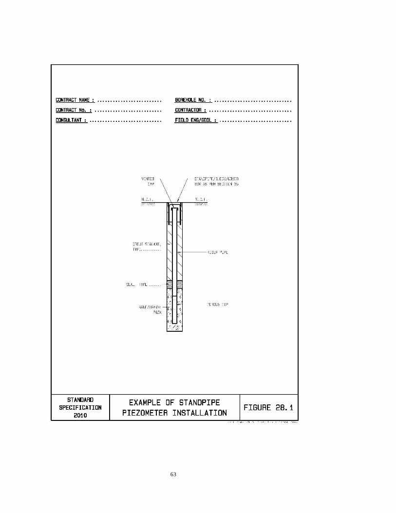
63

64
SECTION 29 INCLINOMETERS 29.1 DESCRIPTION
This section relates to the supply and installation of an inclinometer system to monitor the amount and location of lateral movements of structures and slopes. A detailed method statement setting out the procedures to be followed and the equipment to be employed shall be submitted to the Engineer for his approval at least 10 Working Days prior to any installation. The casing to be supplied and installed may be either plastic or aluminium and have four longitudinal grooves on the inside of the casing at 90º spacing as manufactured by Slope Indicator Company, Seattle, WA, USA, or similar which has been proven to be compatible with the intended monitoring equipment. The internal and external diameters of the casing shall be selected to suit the size of hole drilled but will always be as close as possible to the internal diameter of the hole drilled. Individual casing lengths shall be glued using a conventional solvent – cement (PVC Weld or similar) and/or pop-riveted as necessary. Prior to the installation of the inclinometer casing the orientation at which the measurement grooves are to be installed shall be agreed and approved by the Engineer. The installation of the casing shall typically proceed as follows: (i) Fill hole with bentonite : cement grout (nominal 3:1 in 8 to 12 parts water).
(ii) Withdraw borehole casing.
(iii) Insert inclinometer casing (sealed at bottom) into borehole ensuring that it is inserted
to the correct depth. (iv) Weight or clamp casing to hold it in position and ensure that it will not move down
vertically if not inserted right down to the bottom of the hole.
(v) Twelve to twenty-four hours later, after the grout has achieved an initial set and the casing no longer tends to float out of the hole, remove weights and clamps and flush out the casing using clean water.
All joints in the casing shall be sealed using tape, glue or other methods to prevent the entry of grout into the casing. If required, telescopic sections shall be incorporated in the casing. The bottom of the casing shall be closed off using a purpose-made plug which shall be glued and riveted/screwed and waterproofed using suitable duct tape. All rivets or screws used shall be non-corrodible (brass, stainless steel, etc). Where the base of the casing is to be rigidly grouted into rock, this shall be with a cement grout and the length of the grouted socket shall normally be 3m. The casing shall be tested for acceptability by inserting the inclinometer (supplied by the Engineer) into the hole for the full depth of the casing. The inclinometer shall be inserted down both sets of grooves. The installation of the casing shall be carried out under the direct supervision of the Engineer and utmost care shall be taken at all times to ensure accuracy of installation and reliability of operation. Utmost care shall be taken to ensure that nothing enters the casing before a permanent protective cover, as detailed in the Project Specifications, has been installed over the collar of the casing (see Section 35). This includes the detail of the connection of the inclinometer casing to the concrete block/collar at ground level, so as to ensure that the top of the casing will not move differentially versus the top of the protective cover and concrete block provided at ground level.
65
29.2 MEASUREMENT AND PAYMENT
The casing shall be measured and paid for per linear metre for the supply and successful installation thereof. The installation rate shall include for the supply of all grout, labour, transport, tools and any other incidentals necessary for the successful installation of the casing. The permanent protective cover shall be measured by number. The inclinometer readings taken following initial installation shall be taken to be included in the installation rate. Any subsequent set of readings shall be measured by number and shall include all costs, including travel, to take the readings.
PAY ITEMS
29. Inclinometers Unit
29.1 Supply of casing metre (m)
29.2 Installation of casing metre (m)
29.3 Permanent protective cover number (no.)
29.4 Taking of readings (per set) number (no.)
66
SECTION 30 WATER SAMPLING AND BOREHOLE WATER REST L EVEL 30.1 DESCRIPTION
The actual level of water in the borehole shall be measured twice daily, at night after completion of drilling and before the start of drilling, as specified in Section 39 and no additional payment shall be made for these measurements. After completion of each hole drilled, except where the Engineer orders the contrary, the elevation of the borehole water rest level must be recorded. If the Contractor neglects to do this timeously, and it becomes impossible to measure the water rest level for any reason, the Engineer may instruct the Contractor to re-drill the hole at his own cost. To record the depth of the water rest level, the borehole is, where feasible, to be pumped or bailed dry, covered against ingress of rain or surface water and left for 24 hours. The water level is to be measured at 24 hourly intervals. Once the water level has become steady over a 24-hour period, this level is to be recorded as the water rest level elevation. If inflow into the hole is such that it cannot practically be bailed or pumped out, the water level after 24 hours shall be taken as the water rest level. The Engineer may, on completion of recording the water rest level elevation, order that a water sample be taken. The sample shall be 2 litres minimum and be placed in a clean, sealed, marked glass container that has been rinsed out with the water being sampled and be delivered to the Engineer’s laboratory. To prevent exsolution of any dissolved gases, only sample containers filled to the brim shall be acceptable. In any hole in which the water rest level is to be measured and in which there is a danger of collapse of the hole, nominal 19mm uPVC tubing shall be installed before removal of casing. Any couplings shall be glued and the lowermost 1 metre of the tubing shall be perforated and covered with a geotextile sock.
30.2 MEASUREMENT AND PAYMENT
The measurement of water rest levels shall be measured by number for each measurement to establish the water rest level. Water samples shall be measured by number. The supply and installation of uPVC tubing shall be measured per linear metre.
PAY ITEMS
30. Water measurements Unit
30.1 Recording water rest levels number (no.)
30.2 Water samples number (no.)
30.3 uPVC tubing metre (m)

67
SECTION 31 CORE BOXES 31.1 DESCRIPTION
This section covers: (a) the quality of the storage boxes in which the cores are stored, (b) the marking of the boxes and (c) temporary storage of the core boxes.
31.2 CORE boxes
For the storage of all soil samples in plastic sleeves and for cores, suitable core boxes made of timber or other approved material shall be provided to comply with the following requirements:
(i) They shall be able to accommodate the size of core specified in the Bill of Quantities
and be 1.50m long (I.D) (ii) Longitudinal partitions to the full depth of the box shall be provided. In the case of N
size core 4 partitions (i.e. to accommodate 7.5m of core) shall be provided. The partitions shall be fixed to the base and ends of the box
(iii) The boxes shall not be more than 500mm wide
(iv) A hinged lid (at least two 50mm hinges) of sufficient thickness to prevent warping
shall be provided.
(v) Two hasps and staples shall be provided on the long side of the box opposite the hinges.
(vi) The boxes shall be acceptable to the Engineer and shall, except if the size of core
drilled dictates otherwise, be of the same external dimensions.
Before drilling may commence, the Contractor shall:
• Firstly, supply a sample core box for the Engineer’s approval. The accepted sample box shall be retained by the Engineer for the duration of the contract for reference purposes,
• Thereafter, ensure that there are always sufficient core boxes (meeting the approved standard) on site to accommodate core production
If, in the opinion of the Engineer, the core boxes are so dirty or poorly marked or if required to minimise weathering, wooden boxes shall be painted inside and out with at least 2 coats of a good quality white PVA (to ensure obliteration of all marks and dirt), to his satisfaction.
31.3 MARKING OF BOXES
The following information shall be indelibly marked on the inside and outside of the lid of the box. All information shall be shall be neat and legible, failing which the Engineer may require the information to be stencilled. Freehand writing shall be allowed on the ends and long side of the box. The following information shall be provided as a minimum:
Information required Example (i) Contract number NRA 170105/4 (ii) Route number and section Road P73/1 (iii) Section name Modimolle - Putberg (iv) Structure name / number Bridge 2475 (v) Borehole number Br 75/1 (vi) Box number and sequence Box 3 of 7
68
(vii) Depth range 8.20 to 14.92 m (viii) Date of contract October 1991
Plus any other information required by the Engineer, all as detailed in the Project Specifications. The information given in (iv) to (vii) shall be marked on the long side of the box (i.e. where hasps and staples are), and (v) to (vi) on both ends of the box.
31.4 PACKING OF THE CORES
The core / samples shall be placed in core boxes in book order and shall be clearly and indelibly marked to define the beginning and end of each drill run and any other intermediate depths required by the Engineer. Colour coded indicator blocks shall be used to demarcate cores lost or removed as follows:
• White painted run blocks, marked with the depth below ground or reference level shall be inserted in the core box at the appropriate point to mark the end of each drill run. These run blocks shall be mechanically fixed to the partitions to prevent any movement of the core or run blocks during handling and transport.
• Yellow painted spacer block approximating the length of the sampled core shall be
substituted for all core which has been sampled and removed for testing purposes. The yellow block shall have the sample number and length of core removed neatly written on it.
• Blue spacer block shall be inserted for lengths of core lost, at the depth where core
was lost, approximating the length of core lost and marked “core loss”. Only core or samples from one drill hole shall be placed in any particular core box. Friable material, material liable to disintegrate (slaking mudstone, etc) or soft or loose material, must, if necessary, be placed in a plastic sleeve, before being placed in the core box. If the core placed in the boxes is liable to move it shall be securely chocked to prevent movement by means of spacer blocks to fill the gaps at the end of core partitions. If required in the Project Specifications, the Contractor shall lay the core on a bedding of bubble wrap folded into the individual core partitions and folded over on top of the core to protect it and prevent movement relative to the lid.
After all the necessary markings and information have been put on the cores and all cores are in the correct position, the core boxes shall be photographed according to the specifications set out in Section 33.
31.5 TEMPORARY STORAGE OF CORE BOXES
All core boxes shall be stored at the site of a borehole until such time as drilling of the hole is complete, whereafter they may be removed to storage at the Contractor’s camp or any other site as approved and ordered by the Engineer. No core boxes may be removed from the site without the written instruction of the Engineer. Core stored temporarily on the site shall at all times be protected against exposure to the elements or damage of any nature. They shall at all times be covered with a waterproof cover and shall be stored at least 200mm above ground level. Any core boxes that become unserviceable due to exposure to the weather shall be replaced by the Contractor The Contractor shall remain responsible for the protection and safekeeping of the samples and core boxes until they have been photographed and delivered to the place of permanent storage, whereupon they become the responsibility of the Engineer.

69
31.6 MEASUREMENT AND PAYMENT
The measurement for the supply of core boxes will be the number of core boxes actually used for the storage of core or samples to the satisfaction of the Engineer. No separate measurement or payment will be made for the temporary storage of core.
PAY ITEMS
31. Core boxes Unit
31.1 Core boxes number (no.)

70
SECTION 32 CORE SHEDS 32.1 DESCRIPTION
This section relates to the provision of core sheds for the permanent storage of core boxes. 32.2 CORE SHED
The size of the core shed and the number of core boxes to be accommodated shall be detailed in the Project Specifications and shall be built as early as possible during the contract (and the Contractor shall programme accordingly) to permit safe storage of the core. The shed may be a standard, commercially available unit, but the following general requirements shall apply:
• The walls shall be at least 2.4m high • The roof shall:
o have a slope of at least 1:6 o include clear panels for illumination (min. 5% of roof area) o have an overhang of at least 500mm all round
• The concrete floor shall slope for drainage • The door shall be big enough to allow access for a loaded LDV • It shall be weather and vandal proof • The shed shall be positioned as agreed with the Engineer, taking into account
aspects such as access, prevailing wind and rain directions and drainage. • A 50mm brass padlock (insurance grade 3 or better) with 3 keys shall be provided. • The hasp and padlock shall be protected against vandalism by a steel pipe welded
to the door / frame, which allows access to the end of the padlock to unlock it. • It shall be of such a size that the boxes may be stacked in such a way to permit
access to individual boxes without having to unpack all the boxes. • All boxes shall be raised at least 100mm above the floor. • Where termites may occur, boxes shall be placed on core racks and the feet shall be
inserted into oil-filled (minimum 100mm deep, SAE30) tins to prevent termites reaching the boxes. In addition, all boxes shall be treated with an approved insecticide and painted as detailed in Section 31.
The site of the shed(s) shall be detailed in the Project Specifications or timeously decided by the Engineer during the contract to permit the Contractor time to complete the shed(s) within the contract period, all as detailed in the Contractor’s programme. The Contractor shall provide detail of the core shed that he proposes to supply with his tender.
32.3 CORE RACKS
Core racks, if required in the Project Specifications, shall be provided in modules of nominal 2,1 x 1,2m size erected parallel to the long walls of the shed. The rack module is to meet the following requirements: (i) an overall loading of 1600 kg per module; (ii) is entirely dismantleable;
32.4 ARRANGEMENT OF BOXES
Core boxes shall be packed into the core shed in a sequence to be agreed with the Engineer and in such a way to allow access in future to locate and remove particular core boxes. The boxes shall be arranged in such a way that core boxes from a single borehole shall be in

71
sequence and also be grouped relative to their origin. For example, all the core boxes from a single structure or cutting shall be grouped. The Contractor shall provide a neat schematic inventory indicating the location of individual boxes within the shed. One copy of the schematic shall be given to the Engineer and a copy permanently fastened to the wall of the shed, in a prominent position, in a sealed, weatherproof plastic envelope(s), such that the schematic may be read through the plastic. The schematic shall be checked and certified by the Engineer.
32.5 NAME BOARD
If required in the Project Specifications, a name board shall be securely fastened above the core shed door, right under the overhang to protect it against the elements. The name board shall be 750 x 500 x 2mm, rust proofed, undercoated and painted white (enamel), mild steel (or similar, approved equivalent). Such names/lettering as detailed in the Project Specifications shall be neatly and indelibly stencilled on the board.
32.6 MEASUREMENT AND PAYMENT
Core sheds shall be measured by number erected to the satisfaction of the Engineer and shall include for all erection, transport, labour, tools and any incidentals necessary. Core racks shall be measured by number for each module and shall include all costs for transport, erection, tools, planking and any incidentals necessary. Name boards shall be measured by number and shall include for all materials, labour, mounting, painting, stencilling and any incidentals necessary.
PAY ITEMS
32. Core sheds Unit
32.1 Core shed number (no.)
32.2 Core rack module number (no.)
32.3 Name board number (no.)

72
SECTION 33 CORE PHOTOGRAPHY 33.1 DESCRIPTION
This section relates to the taking, for record purposes, of photographs of all core, samples or any other items requiring to be photographed by the Engineer. At least two weeks prior to commencing photography the Contractor shall supply, for the Engineer’s approval, a sample photograph which will be used as a standard to judge the photographs supplied under the contract. The Engineer shall retain the accepted photograph as a reference until completion of the contract.
33.2 QUALITY OF PHOTOGRAPHS
The Contractor shall provide digital photographs in jpeg format with a resolution of at least 3.5 Mega pixels and a maximum file size of 700 Kbytes per photograph, in order to provide a realistic total file size.. The photographs shall comply with the following:
(i) The digital photos shall be professionally printed on semi-gloss paper to a size of 150 x 100mm (nominal) (i.e. jumbo size) with 2 photos per A4 page. The file number shall be printed at the base of the photo as required in 32.4. Two hard copies of each page shall be provided and each bound into a separate albums.
(ii) A standard colour chart shall be included in the photograph, an original copy of
which shall be included with the photos for reference purposes. (iii) The box shall occupy between 85 and 95% of the long dimension of the photo. (iv) Plastic sleeves shall be cut or folded back so that the material therein is clearly
visible. After photography, core or samples that were in plastic sleeves, shall be resheathed.
(v) Core will normally not be wetted before photography. (vi) No shadows are permitted on the core. (vii) The box shall be parallel to all four sides of the photograph. (viii) All written data must be clearly legible. (ix) The photographs must be clear and in focus and shall not be over- or under-
exposed. (x) The core box shall be orientated so that the core reads like a book in increasing
depth from top left.
The core box shall be positioned relative to the photographer to ensure that the photograph is not oblique to the pole of the centre of the box. Photographs shall preferably be taken in natural light, but not in direct sunlight. Where a flash is used, care shall be taken that this does not produce a bright stripe down the length of the core (most likely to occur when the core is wetted) or reflections from the data box. These may be avoided by using twin flashes angled towards the core box from either side of the camera position.
73
33.3 IDENTIFICATION DATA
This shall be provided by way of a photographic data title box, which will be as follows: (i) Have dimensions closely approximating the lid of the standard core box;
(ii) Be painted in matt to minimise glare;
(iii) Have a lettering / numbering set so that the identification data may be composed
from pre-stencilled letters and numbers. These numbers and letters shall be not less than 40mm high, 6mm wide and on a matt background (as per ii above);
(iv) Incorporate a standard colour reference chart, standard grey scale, standard neutral
grey card and a 500mm long scale in 100mm divisions.
The following information shall be included on each photograph (i) That information given in Section 31.3 (i) to (viii)
(ii) The Contractor’s name
(iii) The Consulting Engineer’s name
33.4 PRESENTATION OF PHOTOGRAPHS
The contractor shall supply a CD containing the photographs in jpeg electronic format. The photograph file names on the CD shall be as follows: Contract no_quarry or BP no_Borehole no_Box no_of_no boxes Example For contract N.010-030-2003/1D-SS, Quarry 4, Borehole 4-3, Box 2 of 4 the
file name would be:
N010_030_2003-1D-SS_Q4_BH4-3_Box_2_of_4 The photograph file names on the CD shall be the same as the borehole numbers allocated by the Engineer, and appearing in the photographs. Two colour hard copies of each photograph, as indicated in Section 33.2 above, shall be provided, together with the CD.
33.5 MEASUREMENT AND PAYMENT
The quantity to be measured shall be the number of photographs taken as ordered and approved by the Engineer. Each photograph shall consist of two prints as described in 33.2.
PAY ITEMS
33. Core photography Unit
33.1 Core photographs number (no.)

74
SECTION 34 TRANSPORTATION 34.1 DESCRIPTION
This section relates to the transport of samples and core boxes to laboratories offices or places of permanent storage, as and when ordered by the Engineer. If the distance is less than 50 kilometres the Contractor is required to make provision for the transportation of samples and core boxes to laboratories, offices or places of permanent storage under Section 1, “Establishment of the Contractor on site”. Care shall be taken to ensure that all core boxes and samples shall be delivered in the same condition in which they left the site. A delivery note listing all core boxes or samples shall accompany each delivery and shall be certified by the Engineer. Should the Engineer require regular deliveries of samples or core boxes, the frequency thereof shall be stated in the Project Specifications. In the absence of such a statement the Contractor shall be entitled to assume that all samples and core boxes shall be delivered to permanent storage after completion of the investigations and may be carried out in the minimum number of trips.
34.2 MEASUREMENT AND PAYMENT
The quantity to be paid for shall be the distance in kilometres (when this exceeds 50km), measured in one direction only, from the centre of the site to the laboratory, offices or permanent place of storage or as indicated in the Project Specifications over which the sample or core boxes have to be transported. Distinction shall be made between transport equipment of capacities less than 1.5 ton and greater than 1.5 ton.
PAY ITEMS
34. Transportation of samples and core boxes Unit
34.1 Vehicle of less than 1.5 ton kilometre (km)
34.2 Vehicle of greater than 1.5 ton kilometre (km)

75
SECTION 35 MARKING OF HOLES 35.1 DESCRIPTION
This section relates to the marking of holes, as indicated on the drawings or as ordered by the Engineer. Unless the Engineer orders to the contrary, all holes shall be marked after completion of the hole by one of the two methods (as shown in Figure 35.1) detailed below: (i) Standpipe and cap, alternatively plastic or steel cover
Where it is required, on the order of the Engineer, that access to a hole be maintained a standpipe with lockable cap shall be installed. If there is a risk of vandalisation, the standpipe and cap as shown in Figure 34.1 may be replaced with a lockable plastic water meter-box cover. This shall be a Kent Standard Plastic Meterbox (nominal 310L x 165H x 200mm W – or equivalent, approved similar) cast centrally into the concrete block so that the top of the box is flush with the top of the concrete. See Figure 35.2. If boreholes are located where pedestrian or vehicular traffic is present, a steel cover box (Besaans VP meter box or equivalent approved similar) shall be provided, as detailed on Figure 35.2.
(ii) Concrete block only
All holes not marked as (i) above shall be marked by means of a concrete block. The number of the borehole shall be marked by punching it in figures not less than 10mm high onto an R12 marker rod, before being cast into the concrete. This shall be bent into a cranked shape (see Figure 35.1). The marker rod shall be worked into the concrete such that the top of the rod is level with the top of the block. Any concrete or laitance obscuring the number shall be cleaned off before the concrete sets. The scratching of numbers into wet concrete is not acceptable. Large diameter auger holes shall be marked by means of a concrete block as per (ii) above. The block shall be offset 1m from the edge of the auger hole. The concrete block shall be nominal 1:3:6 concrete. Blocks shall be cast 200mm into, and not on top of the ground. A block made of sand/cement is not acceptable.
35.2 MEASUREMENT AND PAYMENT
The quantity to be paid for shall be the number of holes actually marked to the satisfaction of the Engineer.
PAY ITEMS
35. Marking of holes Unit
35.1 Standpipe and cap number (no.)
35.2 Concrete block only number (no.)
35.3 Plastic water meter box cover number (no.)
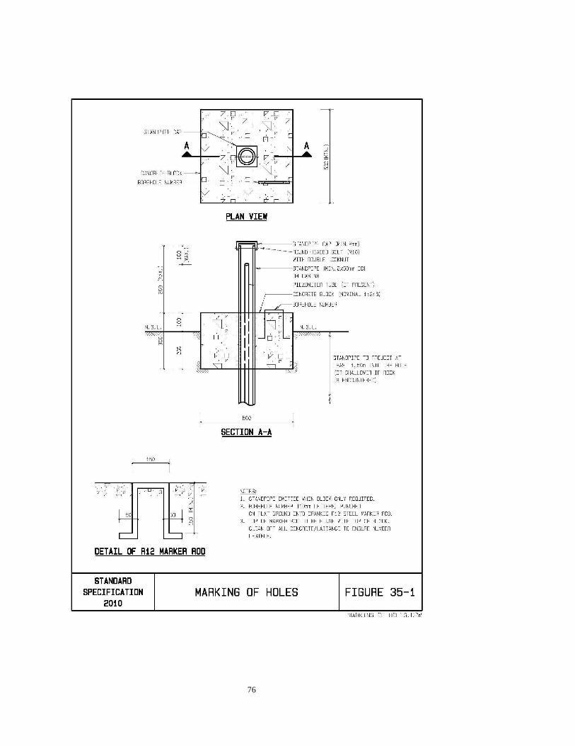
76

77

78
SECTION 36 MACHINE AND HAND TRENCHING 36.1 TRENCHING
Trenching is the formation of trial pits, which are generally long in relation to their width, and are used to expose sections of soil and rock strata for visual examination and possible bulk sampling. Prior to any trenching, the natural vegetation (generally grass) shall be carefully removed (as sods) and placed aside for later replacement. Topsoil shall be stockpiled separate from subsoil. On completion of the trenching, the backfill shall be neatly levelled off (with the topsoil replaced at surface) and the vegetation sods neatly replaced and bedded down over the backfilled area in such a way as to promote their re-growth. Any excess material from the backfilling shall be spread thinly over the surrounding area in such a way as not to prevent the existing vegetation from growing up through it. Trenching may be carried out by machine (as detailed in the Project Specifications), by hand (excluding the use of pneumatic tools), or a combination of the two. The minimum width of trench, which is acceptable, shall be 0.5m. The specified machine shall be provided on a daily hire basis (inclusive of fuel and operator) and shall be supplied to the Engineer, who will direct operations, including trenching positions, depths, sampling positions and the preparation of soil profiles. The machine shall be available on site for 10 hours on each day that it is required. Should the machine break down for more than an hour in any one day, payment for that day shall be reduced proportionately relative to the time when the machine was operative, with the provision that should it be inoperative for more than 4 hours in any one day, it will not be measured at all for that day. The cost of repair of any services damaged during trenching carried out under the direction of the Engineer shall be to the cost of the Employer. At all times strict safety precautions must be observed. No person shall be allowed to excavate by hand or enter into a trench in excess of 1.5m depth unless the sides have been adequately shored to the satisfaction of the Engineer. Hard hats must be worn at all times by labourers during excavation and any personnel who enter such trenches. The safety precautions as given in “A code of practice on the safety of persons working in small diameter shafts and test pits for civil engineering purposes, 2007” as published by SAIEG, SAICE Geotechnical Division and AEG are applicable to this work. Such sampling as may be required by the Engineer shall be carried out in accordance with Section 16. After inspection by the Engineer, the trench must immediately be backfilled to the satisfaction of the Engineer. All material excavated from the trench shall be heaped above the hole and if the backfill settles more than 300mm below the surrounding ground level, the Contractor shall provide and compact such additional material to fill up to ground level. For the purpose of this section, any settlement which occurs within one month of completion of the hole, or the completion of the works (whichever is the longer) shall be the Contractor’s responsibility. If the Engineer instructs any trench to remain open, a suitable fence comprising at least 4 strands of suitably spaced wire wrapped with plastic danger tape, strained between approved Y-section metal standards or 75mm diameter creosoted wooden poles spaced not more than 2m apart, to the satisfaction of the Engineer, shall be erected by the Contractor so that the trench area is fully demarcated and enclosed. If the open trench is near roadways, or habitation, battery powered warning lights must be provided overnight until such time as the hole has been backfilled to the satisfaction of the Engineer as above. The fence shall be erected sufficiently far, as agreed to by the Engineer, from the edges of the trench to ensure that it continues to function even if the sides of the trench collapse. The Engineer may instruct that trenching be carried out at the position of a drill or auger hole to determine the presence of services.

79
36.2 MEASUREMENT AND PAYMENT
Hand excavation shall be measured and paid for on an hourly rate per labourer employed on this work. Differentiation shall be made for hand excavated trenches not deeper than 1.5m and trenches deeper than 1.5m, the latter to include for the cost of shoring. Machine excavation shall be measured on a daily (10 hour) basis during which the machine is on site on the instructions of the Engineer, in working order and shall include the cost of provision, fuel, operator, supervision by the Contractor and all other incidental costs. Should the machine break down for more than an hour in any one day, payment for that day shall be reduced proportionately relative to the time when the machine was operative, with the provision that should it be inoperative for more than 4 hours in any one day, it shall not be measured at all for that day. Protective fencing shall be measured by the linear metre installed. Backfilling of holes will not be paid for separately, except where holes are ordered to be left open and backfilled after the trenching phase of the investigation has been completed. In this event the number of holes backfilled shall be measured.
PAY ITEMS
36. Machine and hand trenching Unit
36.1 Hand excavation
35.1.1 Up to 1.5m depth hour (h)
35.1.2 In excess of 1.5m depth hour (h)
36.2 Machine excavation (by type)
35.2.1 Tractor-loader-backhoe (TLB) (specify size) hay (d)
35.2.2 Excavator (specify size) hay (d)
36.3 Safety fencing metre (m)
36.4 Backfilling of holes (only as ordered by Engineer) number (no.) NOTE: Establishment shall be measured and paid for under Section 3. Details of the machine to be provided (kW rating, bucket size, depth capacity, etc) shall be specified in the Project Specifications.

80
SECTION 37 STANDING TIME 37.1 DESCRIPTION
Should the Contractor at any time during the contract period be required to discontinue the Works on the site as a result of a written order from the Engineer, or because the Contractor is awaiting instructions, approval or decisions of the Engineer, with the result that the Contractor’s workers and equipment cannot otherwise be gainfully employed, he shall be entitled to compensation for such time loss during normal working hours. Standing time shall only be applicable in respect of major units of equipment such as drilling rigs, auger rigs, bulldozers, TLBs and excavators. It is stressed however, that standing time during normal working hours and on Working Days is only applicable should the work be stopped by order of the Engineer, or where decisions are being awaited from the Engineer. It shall be expected of the Contractor to notify the Engineer in writing one full day ahead that he will require instructions, approval or other decisions at a certain time. Without such prior written notice, no standing time compensation shall be considered. Standing time does NOT include time when drilling is discontinued for the purposes of taking directional, angular or any other readings, or activity in connection with the work and the Contractor himself carries out these operations. Where a third party, over whose operations the Contractor has no control, carries out the tests or surveys, standing time shall apply. The Contractor shall however programme and co-ordinate his operations and those of the third party in such a way to minimise the likelihood of standing time.
37.2 WORKING HOURS For the purpose of calculating standing time, “normal working hours” shall be taken from 07:00 to 17:00 on Mondays to Fridays and 07:00 to 13:00 on Saturdays (statutory holidays excluded), which defines a Working Day. If the Contractor should find it necessary to extend normal working hours by working longer hours and/or by working during weekends and holidays, he shall acquire the Engineer’s approval at least 3 Working Days prior to such extension of working hours, and shall furnish reasons for his request. In this regard attention is drawn to the Conditions of Contract for this contract. Such approval shall only be given on a week-to-week basis and can be withdrawn by the Engineer at any time. Without the Engineer’s prior written approval, no standing time shall be paid outside of normal working hours.
37.3 MEASUREMENT AND PAYMENT
Standing time shall only be measured for payment for periods in excess of one hour. The actual measurement will be made for the full period during which standing time was agreed for any specific unit of plant measured to the nearest 0.25 hour.
PAY ITEMS
37. Standing time Unit
37.1 Standing time (Specify different plant) hour (h)
81
SECTION 38 LOGGING AND PROFILING 38.1 DESCRIPTION
This section relates to the logging of borehole cores, percussion samples and the profiling of large diameter auger holes, trenches or test pits by a competent specialist approved of or selected by the Engineer and approved of by the Employer. In the event that the Engineer requires the boreholes to be logged and profiles recorded under the Contract, the specialist shall be an Engineering Geologist who is Member of the South African Institute of Engineering Geologists (SAIEG), or under the direct supervision of such a Member. An experienced Geotechnical Engineer (registered with ECSA and a Member of the Geotechnical Division of SAICE) may also undertake this work, but only if timeous approval has been obtained from the Employer. The work shall be carried out in accordance with “Guidelines for soil and rock logging in South Africa”, editors ABA Brink and RMH Bruin. Proceedings of the Geoterminology Workshop 1990. Produced by SAIEG, SAICE Geotechnical Division and AEG. Second Impression, 2002 The Contractor shall furnish assistance in respect of labour, equipment or the supply of information and results as may be requested by the specialist to enable him to carry out his tasks. These operations shall be measured and paid for under the relevant sections of these specifications. The Contractor shall provide a site for the logging which is under cover and where the core boxes can be placed on drums or similar to raise them to about waist height. Standing time shall be applicable if the actions of the specialist result in on-site delays to the Contractor. The logs and profiles supplied by the specialist shall be neatly typed on standard forms (see examples in Figure 38.1 to 38.3).
38.2 MEASUREMENT AND PAYMENT
The services of the specialist shall be paid for as a provisional sum. Reimbursement of the cost will be made only after provision of acceptable proof to the Engineer of payment by the Contractor to the supplier.
PAY ITEMS
38. Logging and profiling Unit
38.1 Services of specialist provisional sum (P sum)
38.2 Mark up for handling and profit percent (%)

82
FIGURE 38.1: EXAMPLE OF TRIAL PIT PROFILE

83
FIGURE 38.2: EXAMPLE OF CORE BOREHOLE LOG

84
FIGURE 38.3: EXAMPLE OF PERCUSSION BOREHOLE LOG

85
SECTION 39 PREPARATION OF RECORDS 39.1 DESCRIPTION
This section relates to the preparation and submission of records of work during the investigation. Records shall be kept on forms approved by the Engineer.
39.2 DAILY JOURNALS
The Contractor shall prepare individual Daily Journals for each drill rig or major equipment unit (see example of Daily Drilling Journal as Figure 39.1) and these shall be submitted to, and agreed with the Engineer within 24 hours of the completion of each day’s operations. A typical Percussion Drilling Journal is shown in Figure 8.1. The record shall contain the following information, where relevant:
(a) Contract name, location and stake value (b) Contractor’s and driller’s names (c) Weather conditions (d) Exploratory hole/pit/test position number (e) Date of boring, pitting and testing referred to and the depth at the end of
each working day or shift (f) Plant in use and rig number (g) Diameters, depths and types of all casings used (h) Approximate depth of each change of stratum (i) Brief description of each stratum (j) Records of all water levels encountered with full details of any fluctuations.
(includes standing water levels in the drill holes before drilling commences each morning and at the end of the day)
(k) Orientation of the drill hole, given as its azimuth and inclination below horizontal (eg. 312°/68°)
(l) Method of penetration and flushing system (m) Type of core barrel and bit used (n) Depth of start and finish of each core run (o) Condition of out coming flush water, water return and loss, and the nature of
the cuttings, drilling aid used (p) Total core recovery with information as to possible location of core losses (q) details of backfilling and grouting (r) Records of any tests, their depths of execution and results (s) Records of any samples taken (t) Records of any downtime, delays, etc
The report shall also include a brief description of any difficulties encountered during operations and any relevant information in respect of the character of the sub-surface conditions, such as cavities, obstacles, use of special type samplers or traps, etc. The Daily Journals shall be required for every Working Day that a drill rig or major equipment unit is on site, whether or not it is operative. These Daily Journals shall be accepted as a substantial record of the operations on site and it is in the Contractor’s interest to ensure that these are as detailed as possible. Claims for extension of time (and any other claims) that the Contractor may have, will be based on these records. Should the Contractor not supply Daily Journals within the stipulated time period, the Engineer shall have the right to instruct the Contractor to stop work with the particular unit of equipment until such time as all the outstanding Daily Journals have been supplied to him. Additionally, the Engineer has the right to reject any claim from the Contractor which cannot be substantiated by Daily Journals in the Engineer’s possession.

86
39.3 PRACTICAL COMPLETION RECORDS
In order that a certificate of practical completion of the work, as per the Conditions of Contract, may be issued to define the actual Time of Completion of the field operations, the following records shall be provided: (i) Daily Journals; (ii) Borehole water rest levels; (iii) List of undisturbed samples handed to the Engineer; (iv) Any notifications of intention to claim; (v) List of all boreholes marked; (vi) Clearance certificates from landowners (see Figure 1.1); (vii) The results of any field testing carried out (except that carried out by specialist
subcontractors); (viii) Written approval from the Engineer allowing removal from site of the Contractor’s
plant and equipment; (ix) Any other items as may be specified in the Project Specifications or timeously
requested in writing by the Engineer. 39.4 RECORDS FOR FINAL PAYMENT CERTIFICATE
In addition to the above records, the Contractor shall supply the following before issue of the final payment certificate: (i) Core photographs; (ii) Final and agreed quantities; (iii) Proof of payment to all suppliers of prime cost and provisional sum items; (iv) Final logs and profiles required under Section 38; (v) List of all core boxes delivered to permanent storage; (vi) The results of any testing, survey, etc. performed by specialist subcontractors ; (vii) Proof that any matters requiring attention under Section 40: Occupational Health
and Safety and Section 41: Environmental Management have been satisfactorily attended to.
(viii) Any other matters as specified in the Project Specifications or timeously requested in writing by the Engineer.
39.5 MEASUREMENT AND PAYMENT
No payment shall be made for the preparation and submission of records and any costs shall be deemed to be included in the relevant rates tendered for the Works.

87
EXAMPLE OF DAILY DRILLING JOURNAL
Contractor: BEST GEOTECH DRILLERS Pty Ltd Page 1.. of 1… Borehole No. Br15/3
Client: XYZ Rig, no. & model: Seco B12 Drilling
Project: N4/8 NELSPRUIT BYPASS Gateway - Karino
Driller: M A Buick Type From To Total
Contract no: NRA017020982 Supervisor: D Ford Auger 0 3.00 3.00
Site: Bridge 15 Start/End Date
04/03/2007 07/03/2007 NWD4 3.00 9.96 6.96
Water Rest Level: S.P.T. (no): 2 TNW 9.96 12.65 2.69
Inclination (° below horizontal): 30º
Block only: SP + block: 1 Casing 0 3.25 3.25
Direction/Azimuth: 150º
UDS (no): 1 Piezo 0 12.50 12.50
Set-up: Skid 150m Core Boxes: 2 Final depth: 12.65m Grout 0
Depth Drilled Run Core
Recovered Drill water
Test Depth
S.P.T.
Date
((dd
/mm)
start/e
nd
time
Drilling
Type
From (m)
To (m)
Adv (m).
m %
Strata Description
and comments
Drill
category
(A,B etc). Colour % (m) blows/ 75mm
4 Mar A 0 1.50 1.50 na
(07:15) SPT 1.50 1.95 1.50 2/3/2/3/2/4
UDS 1.95 2.50 1.95 Shelby
A 2.50 3.00 1.50 Water added na
SPT 3.00 3.20 na 3.00 10/20/25
NWD4 3.00 4.50 1.50 Wash 0 Brown 100
4.50 5.96 1.46 1.30 89 Red 100
(16:50) 5.96 7.36 1.40 1.10 79 Grey 75
DWLpm = 3.30m
5 Mar DWLam = 8.50m
(07:00) TNW 9.96 11.46 1.50 1.50 100 DWLpm = 4.40m White 100
(09:00) Gearbox broke 09:00 #
6 Mar Standing, no water truck #
7 Mar TNW 11.46 12.65 1.19 1.10 92 DWLam = dry White 50
(07:00)
DWLpm = 4.10m
Hole stopped on instruction of Engineer at 10:00, moved to hole Br15/5.
0 – 3.00 Red brown clay Aug
3.00 – 5.96 Weathered dolerite
B
Shelby sample delivered to RE. Standpipe piezometer installed in hole.
9.96 – 12.65m Hard dolerite C
Remarks: Drill water level to be measured mornings before drilling & evenings at end of day.______________ DWLam = am Drill Water Level DWLpm = pm Drill Water Level__ # rig not working, do not measure under Section 3______________________________________
Figure 39.1: Example of Daily Drilling Journal (DDJ )

88
SECTION 40 OCCUPATIONAL HEALTH AND SAFETY 40.1 DESCRIPTION
This section covers the development of an Occupational Health and Safety plan that addresses all aspects of occupational health and safety in order to comply with the Occupational Health and Safety (OHS) Act, No. 85 of 1993, and Construction Regulations (2003), which the Contractor shall comply with in order to reduce the risks associated with the contract that may lead to incidents causing injury and/or ill health.
A Contractor shall, as a minimum, comply with: • The OHS Act and Regulations (Act 85 of 1993), and Construction Regulations, plus any
amendments. An up-to-date copy of which shall be available on site at all times. • The Compensation for Occupational Injuries and Diseases (COID) Act (Act 130 of 1993),
plus any amendments. An up-to-date copy of which shall be available on site at all times. • Where work is being carried out on a “mine”, the Contractor shall comply with the Mines
Health and Safety Act and Regulations (Act 29 of 1960), plus any amendments, and any other OH&S requirements that the mine may specify. An up-to-date copy of the Mines Health and Safety Act and Regulations shall be available on site at all times.
Compliance with this section does not absolve the Contractor from complying with minimum legal requirements and the Contractor remains responsible for the health and safety of his Employees and those of his mandataries.
40.2 HAZARD IDENTIFICATION AND RISK ASSESSMENT (Con struction Regulation 7) 40.2.1 Risk Assessments
The Standard Specifications contain a generic list of project risks that have been identified as possibly applicable to the contract. It is, by no means, exhaustive and is offered as assistance to Contractors intending to tender.
40.2.2 Development of Risk Assessments
The Contractor shall, before the commencement of any construction work, perform a risk assessment by a competent person, appointed in writing, and the risk assessment shall form part of the OHS plan and be implemented and maintained as contemplated in Construction Regulation 5(1).
The risk assessment shall include, at least:
• the identification of the risks and hazards to which persons may be exposed • the analysis and evaluation of the risks and hazards identified • a documented plan of safe work procedures to mitigate, reduce or control the risks and
hazards that have been identified • a monitoring plan and • a review plan
Based on the risk assessment, the Contractor shall develop a set of site-specific OHS rules that shall be applied to regulate the OHS aspects of the construction. The risk assessment, together with the site-specific OHS rules shall be submitted to the Employer before construction on site commences. Despite the risk assessments listed in paragraph 39.4, the Contractor shall conduct a baseline risk assessment and the aforesaid listed risk assessment shall be incorporated into the baseline risk assessment. The baseline risk assessment shall further include the standard working procedures and the applicable method statements based on the risk assessments
All variations to the scope of work shall similarly be subjected to a risk assessment process.

89
40.2.3 Review of Risk Assessment
The Contractor shall review the hazard identification, risk assessments and standard working procedures at each planning and progress report meeting as the contract work develops and progresses and each time changes are made to the designs, plans and construction methods and processes. The Contractor shall provide the Employer, Sub- contractors and all other concerned parties with copies of any changes, alterations or amendments as contemplated herein.
40.3 STRUCTURE AND RESPONSIBILITIES
40.3.1 Overall Supervision and Responsibility for OH&S
It is a requirement that the Contractor, when he appoints contractors (Sub-contractors) in terms of Construction Regulations 5(3), 5(5), 5(9), 5(10) and 5(12) includes in his agreement with such contractors the following: • OHS Act (85 of 1993), Section 37(2) agreement: “Agreement with Mandatory” • OHS Act (85 of 1993), Section 16(2) appointee/s as detailed in his/her/their respective
appointment forms. 40.3.2 Further (Specific) Supervision Responsibilities for OHS
The Contractor shall appoint designated competent employees and/or other competent persons as required by the Act and Regulations. Below is a generic list of identified appointments and may be used to select the appropriate appointments for this contract. The Contractor shall note that it is a generic list only and is intended for use as a guideline. Ref. Section/Regulation in OHS Act Construction Vehicles/Mobile Plant/Machinery Supervisor
Construction Regulation 21
Demolition Supervisor Construction Regulation 12 Drivers/Operators of Construction Vehicles/Plant Construction Regulation 21 Electrical Installation and Appliances Inspector Construction Regulation 22 Emergency/Security/Fire Coordinator Construction Regulation 27 Excavation Supervisor Construction Regulation 11 Explosive Powered Tool Supervisor Construction Regulation 19 Fall Protection Supervisor Construction Regulation 8 First Aider General Safety Regulation 3 Fire Equipment Inspector Construction Regulation 27 Formwork & Support Work Supervisor Construction Regulation 10 Hazardous Chemical Substances Supervisor HCS Regulations Incident Investigator General Admin Regulation 29 Ladder Inspector General Safety Regulation 13A Lifting Equipment Inspector Construction Regulation 20 Materials Hoist Inspector Construction Regulation 17 OHS Committee OHS Act Section 19 OHS Officer Construction Regulation 6(6) OHS Representatives OHS Act Section 17 Person Responsible for Machinery General Machinery Regulation 2 Scaffolding Supervisor Construction Regulation 14 Stacking & Storage Supervisor Construction Regulation 26 Structures Supervisor Construction Regulation 9 Suspended Platform Supervisor Construction Regulation 15 Tunnelling Supervisor Construction Regulation 13 Vessels under Pressure Supervisor Vessels under Pressure Regulations Working on/next to Water Supervisor Construction Regulation 24 Welding Supervisor General Safety Regulation 9
In the event that the investigation takes place on, or next to a public road, the Employer may require that a Traffic Safety Officer be appointed. The above appointments shall be in writing and the responsibilities clearly stated together with the period for which the

90
appointment is made. This information shall be communicated and agreed with the appointees. Notice of appointments shall be submitted to the Employer. All changes shall also be communicated to the Employer.
The Contractor shall, furthermore, provide the Employer with an organogram of all contractors that he/she has appointed or intends to appoint and keep this list updated and prominently displayed on site. Where necessary, or when instructed by an inspector of the Department of Labour, the Contractor shall appoint a competent construction safety officer.
40.3.3 Designation of OHS Representatives (Section 17 of the OHS Act)
Where the Contractor employs more than 20 persons (including the employees of other contractors (sub-contractors) he has to appoint one OHS representatives for every 50 employees or part thereof. General Administrative Regulation 6 requires that the appointment or election and subsequent designation of the OHS representatives be conducted in consultation with employee representatives or employees. (Section 17 of the Act and General Administrative Regulation 6 & 7). OHS representatives shall be designated in writing and the designation shall include the area of responsibility of the person and term of the designation.
40.3.4 Duties and Functions of the OHS Representatives (Section 18 of the OHS Act)
The Contractor shall ensure that the designated OHS representatives conduct continuous monitoring and regular inspections of their respective areas of responsibility using a checklist and report thereon to the Contractor. OHS representatives shall be included in accident or incident investigations. OHS representatives shall attend all OHS committee meetings of which they are members, where such committee has been appointed.
40.3.5 Appointment of OHS Committee (Sections 19 and 20 of the OHS Act)
The Contractor shall establish an OHS committee where 2 or more representatives have been appointed for that workforce, they shall meet as specified in the Regulations.
40.4 ADMINISTRATIVE CONTROLS AND THE OCCUPATIONAL H EALTH & SAFETY FILE 40.4.1 The OHS File (Construction Regulation 5 (7))
As required by Construction Regulation 5(7), the Contractor and Sub- contractors shall each keep an OHS file on site. The following list is not exhaustive and shall only be used as a guide: • Notification of construction work (Construction Regulation 3) • Latest copy of OHS Act (General Administrative Regulation 4) • Proof of registration and good standing with COID Insurer (Construction Regulation 4 (g) • OHS plan agreed with the Employer including the underpinning risk assessment/s and
method statements (Construction regulation 5 (1)) • Copies of OHS committee and other relevant minutes • Designs/drawings (Construction Regulation 5 (8) • A list of contractors (sub-contractors) including copies of the agreements between the
parties and the type of work being done by each contractor (Construction Regulation 9) • Appointment/designation forms as per paragraphs 2.1.1 and 2.1.2. • Registers as follows:
o Accident/Incident register (Annexure 1 of the General Administrative Regulations) o OHS representatives’ inspection register o Construction vehicles and mobile plant inspections by controller o Daily inspection of vehicles, plant and other equipment by the operator/driver/user o Demolition inspection register o Designer’s inspection of structures record o Electrical installations, -equipment and -appliances (including portable electrical
tools) o Excavations inspection o Explosive powered tool inspection, maintenance, issue and returns register (incl.
cartridges and nails)

91
o Fall protection inspection register o First aid box contents o Fire equipment inspection and maintenance o Formwork and support work inspections o Hazardous chemical substances record o Ladder inspections o Lifting equipment register o Materials hoist inspection register o Machinery safety inspection register (incl. machine guards, lock-outs etc.) o Scaffolding inspections o Stacking and storage inspection o Inspection of structures o Inspection of suspended platforms o Inspection of tunnelling operations o Inspection of vessels under pressure o Welding equipment inspections o Inspection of work conducted on or near water o All other applicable records including traffic safety officer reports.
The Employer will undertake audits on the OHS file of the Contractor from time-to-time.
40.5 TRAINING AND COMPETENCE
The contents of all training required by the Act and Regulations shall be included in the Contractor’s OHS plan. The Contractor shall be responsible for ensuring that all relevant training is undertaken. Only accredited service providers shall be used for OHS training. The Contractor shall ensure that his and Sub-contractors’ personnel appointed are competent and that all training required to do the work safely and without risk to health, has been completed before work commences. The Contractor shall ensure that follow-up and refresher training is conducted as the contract work progresses and the work situation changes. Records of all training must be kept on the OHS file for auditing purposes.
40.6 CONSULTATIONS, COMMUNICATION AND LIASON
OHS liaison between the Employer, the Contractor, the Sub-contractors, the designer and other concerned parties will be through the OHS committee as contemplated in paragraph 39.3.5. In addition to the above, communication may be directly to the Employer or his appointed agent, verbally or in writing, as and when the need arises.
Consultation with the workforce on OHS matters will be through their supervisors, OHS representatives and the OHS committee. The Contractor shall be responsible for the dissemination of all relevant OHS information to the Sub-contractors e.g. design changes agreed with the Employer and the designer, instructions by the Employer and/or his/her agent, exchange of information between contractors, the reporting of hazardous/dangerous conditions/situations etc. The Contractors’ most senior manager on site shall be required to attend all OHS meetings.
40.7 CHECKING, REPORTING AND CORRECTIVE ACTIONS 40.7.1 Monthly Audit by Employer (Construction Regulation 4(1)(d)
The Employer will conduct monthly audits to comply with Construction Regulation 4(1)(d) to ensure that the Contractor has implemented and is maintaining the agreed and approved OHS plan.

92
40.7.2 Other Audits and Inspections by the Employer
The Employer reserves the right to conduct other ad hoc audits and inspections as deemed necessary. This will include site safety walks.
40.7.3 Contractor’s Audits and Inspections
The Contractor is to conduct his own monthly internal audits to verify compliance with his own OHS management system as well as with this specification.
40.7.4 Inspections by OHS Representative’s and other Appointees
OHS representatives shall conduct weekly inspections of their areas of responsibility and report thereon to their foreman or supervisor whilst other appointees shall conduct inspections and report thereon as specified in their appointments e.g. vehicle, plant and machinery drivers, operators and users must conduct daily inspections before start-up.
40.7.5 Recording and Review of Inspection Results
All the results of the abovementioned inspections shall be in writing, reviewed at OHS committee meetings, endorsed by the chairman of the meeting and placed on the OHS File.
40.8 ACCIDENTS AND INCIDENT INVESTIGATION (GENERAL ADMINISTRATIVE
REGULATION 9)
The Contractor shall be responsible for the investigation of all accidents/incidents where employees and non-employees were injured to the extent that he/she/they had to be referred for medical treatment by a doctor, hospital or clinic. The results of the investigation shall be entered into an accident/incident register listed in paragraph 39.4.1. The Contractor shall be responsible for the investigation of all minor and non-injury incidents as described in Section 24 (1) (b) & (c) of the Act and keeping a record of the results of such investigations including the steps taken to prevent similar accidents in future.
40.9 REPORTING
The Contractor shall provide the Employer with copies of all statutory reports required in terms of the Act within 7 days of the incident occurring.
40.10 OPERATIONAL CONTROL 40.10.1 Operational Procedures
Each construction activity shall be assessed by the Contractor so as to identify operational procedures that will mitigate against the occurrence of an incident during the execution of each activity. This specification requires the Contractor: • to be conversant with Regulations 8 to 29 (inclusive) • to comply with their provisions • to include them in his OHS plan where relevant.
40.10.2 Emergency Procedures
Simultaneous with the identification of operational procedures (per paragraph 39.10.1 above), the Contractor shall similarly identify and formulate emergency procedures in the event an incident does occur. The emergency procedures thus identified shall also be included in the Contractor’s OHS plan.

93
40.10.3 Personal & Other Protective Equipment (Sections 8/15/23 Of The OHS Act)
The Contractor shall identify the hazards in the workplace and deal with them. He must either remove them or, where impracticable, take steps to protect workers and make it possible for them to work safely and without risk to health under the hazardous conditions.
Personal protective equipment (PPE) should, however, be the last resort and there should always first be an attempt to apply engineering and other solutions to mitigating hazardous situations before the issuing of PPE is considered.
Where it is not possible to create an absolutely safe and healthy workplace the Contractor shall inform employees regarding this and issue, free of charge, suitable equipment to protect them from any hazards being present and that allows them to work safely and without risk to health in the hazardous environment.
It is a further requirement that the Contractor maintain the said equipment, that he instructs and trains the employees in the use of the equipment and ensures that the prescribed equipment is used by the Employee/s.
Employees do not have the right to refuse to use/wear the equipment prescribed by the Employer and, if it is impossible for an Employee to use or wear prescribed protective equipment through health or any other reason, the employee cannot be allowed to continue working under the hazardous condition/s for which the equipment was prescribed but an alternative solution has to be found that may include relocating or discharging the Employee.
The Contractor shall include in his OHS plan the PPE he intends issuing to his Employees for use during construction and the sanctions he intends to apply in cases of non conformance by his employees. Conformance to the wearing of PPE shall be discussed at the weekly inspection meetings.
40.10.4 Other Regulations
Wherever in the Construction Regulations or this specification there is reference to other regulations (e.g. Construction Regulation 22: Electrical Installations and Machinery on Construction Sites) the Contractor shall be conversant with and shall comply with these regulations.
40.10.5 Public Health & Safety (Section 9 of the OHS Act)
The Contractor shall be responsible for ensuring that non-employees affected by the construction work are made aware of the dangers likely to arise from said construction work as well as the precautionary measures to be observed to avoid or minimise those dangers. This includes: • Non- employees entering the site for whatever reason • The surrounding community • Passers-by to the site
40.11 PROJECT/SITE SPECIFIC REQUIREMENTS 40.11.1 List Of Risk Assessments
• Clearing and Grubbing of the area/site • Site establishment including:
o Office/s o Secure/safe storage for materials, plant and equipment o Ablutions o Sheltered eating area o Maintenance workshop o Vehicle access to the site
• Dealing with existing structures • Location of existing services

94
• Installation and maintenance of temporary construction electrical supply, lighting and equipment
• Adjacent land uses/surrounding property exposures • Boundary and access control/public liability exposures (NB: the Employer is also
responsible for the OHS of non-employees affected by his/her work activities.) • Health risks arising from neighbouring as well as own activities and from the
environment e.g. threats by dogs, bees, snakes, lightning etc. • Exposure to noise • Exposure to vibration • Protection against dehydration and heat exhaustion • Protection from wet and cold conditions • Dealing with HIV/Aids and other diseases • Use of portable & electrical equipment including:
o Angle grinder o Electrical drilling machine o power saws o Electrical generators o Bush cutters o Chain saws o welders
• Excavations including o Ground/soil conditions o Trenching o Shoring o Drainage of trench o Augering
• Welding including o Arc welding o Gas welding o Flame cutting o Use of LP gas torches and appliances
• Loading and offloading of trucks • Aggregate/sand and other materials delivery • Manual and mechanical handling • Lifting and lowering operations • Driving and operation of construction vehicles and mobile plant including:
o Trenching machine o Excavator o Front end loader o Mobile cranes and the ancillary lifting tackle o Parking of vehicles and mobile plant and equipment o Towing of vehicles and mobile plant and equipment
• Use and storage of flammable liquids and other hazardous substances • Layering and bedding • Backfilling of trenches • Protection against flooding • Use of explosives • Protection from overhead power lines • Any other as discovered by the Contractor’s hazard identification exercise • Any other as discovered from any inspections and audits conducted by the Employer or
by the Contractor or any Sub- contractor on site • As discovered from any accident/incident investigation.
40.12 MEASUREMENT AND PAYMENT
Payment for all obligations under this section shall be made under Item 1.1.3.
95
SECTION 41 ENVIRONMENTAL MANAGEMENT 41.1 DESCRIPTION
This section relates to the mitigation measures to be used to minimise the consequences of the contract on the environment. The following philosophies and basic principles of environmental control and rehabilitation have been incorporated into the specifications: a) Any field or drill site is to be restored to its original, virgin state that existed before the
works took place. b) Non-degradable material at the site and in the borehole shall be removed. c) No subsequent deterioration resulting from the works should take place.(e.g. Erosion
or exotic vegetation).
41.2 ENVIRONMENTAL GUIDELINES, LEGISLATION AND STAN DARDS
The Contractor shall identify and comply with all South African national and provincial environmental legislation and any amendments thereof or any legislation enacted in substitution therefore or which repeals same, including associated regulations and all local by-laws relevant to the project. Key national and provincial environmental legislation that is currently applicable to the design, construction and implementation phases of the project that must be compiled with, are included in the following list. The list is intended to serve as a guideline only for the Contractor and is not exhaustive: • Atmospheric Pollution Prevention Act, 1965 (Act No 45 of 1965). • Conservation of Agricultural Resources Act, 1983 (Act No 43 of 1983). • Environmental Conservation Act, 1989 (Act No 73 of 1989). • Explosives Act, 1956 (Act No 26 of 1956). • Fertilisers, Farm Feeds, Agricultural Remedies and Stock Remedies Act, 1947 (Act
No 36 of 1947). • Forest Act, 1984 (Act No 122 of 1984). • Hazardous Substances Act, 1973 (Act No 15 of 1973). • Lake Areas Development Act, 1975 (Act No 34 of 1975). • Land Survey Act, 1921 (Act No 9 of 1921). • Minerals Act, 1991 (Act No 50 of 1991). • National Environmental Management Act, 1998 (Act No 107 of 1998). • National Forests Act, 1998 (No. 84 of 1998). • National Heritage Resources Act, 1999 (Act No 25 of 1999). • National Veld and Forest Fire Act, 1998 (Act No 101 of 1998). • National Water Act, 1998 (Act No 36 of 1998). • Occupational Health and Safety Act, 1993 (Act No 85 of 1993). • Provincial and Local Government Ordinances and Bylaws. • World Heritage Convention Act, 1999 (Act No 49 of 1999). The Contractor shall establish and maintain procedures to keep track of, document and ensure compliance with environmental legislative changes. Where any legislation or regulations referred to in this EMP are repealed, amended or supplemented by any subsequent legislation or regulations which have been duly promulgated and have come into effect, the legislation thus referred to shall be deemed to have been repealed, amended or supplemented by the subsequent legislation or regulation in question, and shall be construed accordingly.
41.3 ENVIRONMENTAL MANAGEMENT PLAN
The generic Environmental Management Plan (EMP) described below sets out environmental specifications to ensure a holistic approach to the management of environmental impacts during subsurface investigation projects.
96
The detailed Environmental Management Plan is a dynamic document subject to similar influences and changes as are wrought by variations to the provisions of the project specification. Any substantial changes to the EMP shall be submitted to the Engineer for approval before any work commences.
41.3.1 Objectives of the EMP
The EMP has the following objectives: • To specify the standards and guidelines that are required in terms of environmental
legislation. • To set out the mitigation measures and environmental requirements for all phases of
the project in order to minimise the extent of environmental impacts, to manage environmental impacts and where possible, to improve the condition of the environment.
• To provide guidance regarding method statements which are required to comply with the environmental specifications.
• To define corrective actions to be carried out in the event of non-compliance with the specifications of this EMP.
• To prevent long-term or permanent environmental degradation.
41.3.2 Legislative Framework
The Contractor has agreed to comply with the EMP, and ensure compliance with the EMP by any third party appointed by the Contractor to fulfil its obligations within the terms and conditions set out in the Contract.
41.3.3 Structure of the EMP
This EMP applies to work undertaken during borrow pit, quarry and subsurface investigations (should exemption be granted by national DEAT) and includes the following: • Background information regarding this EMP document and the Employer. • Definitions relevant to this EMP. • The relevant environmental guidelines, legislation and standards. • General environmental requirements for investigation works. • General environmental requirements relating to the decommissioning of the site. • The requirements for the appropriate management and control of environmental
obligations. 41.4 ENVIRONMENT AND HEALTH TRAINING AND AWARENESS
The Contractor shall ensure that its employees and any third party who carries out all or part of the Contractor’s obligations under the Contract are adequately trained with regard to the implementation of the EMP, as well as regarding environmental legal requirements and obligations. All employees will have an induction presentation on environmental awareness. Where possible, the presentation needs to be conducted in the language of the employees. The environmental training by the Contractor should, as a minimum, include the following:
• The importance of conformance with all environmental policies, procedures, plans
and systems. • Basic awareness and understanding of the key environmental features of the work
site and environs. • Understanding, and importance of, and the reasons why, the environment must be
protected. • Ways to minimise the environmental impacts. • Requirements of the EMP. • Risks and protection from dangerous wild animals, specifically crocodiles (if
applicable). • Prevention and handling of fire. • Emergency procedures.
97
• The significant environmental impacts, actual or potential, as a result of their work activities.
• The environmental benefits of improved personal performance. • Their roles and responsibilities in achieving conformance with the environmental
policy and procedures, including emergency preparedness and response requirements.
• The potential consequences of departure from specified operating procedures. • The mitigation measures required to be implemented when carrying out their work
activities. • The importance of not littering. • The need to use water sparingly. • Details of and encouragement to minimise the production of waste and re-use,
recover and recycle waste where possible. • Details regarding archaeological and/or historical sites that may be unearthed during
construction and the procedures to be followed should these be encountered. • The procedures which should be followed should a grave be encountered or
unearthed during the investigation. • Details regarding floral/faunal species of special concern and protected species, and
the procedures to be followed should these be encountered during the investigation. • All works which may pose a hazard to humans and animals are to be adequately
protected and appropriate warning signs erected. • The Contractor shall provide adequate and operational fire safety equipment at all
times. Personnel on-site shall be trained how to operate fire extinguishers etc. • The use of construction vehicles shall be restricted to authorised personnel, and the
speed limits adhered to at all times. • The Contractor shall ensure that an HIV/AIDS awareness programme is
implemented at the site camp. Weekly or monthly HIV/AIDS awareness topics should be identified which should be broadcast to all employees.
A training needs analysis shall be conducted by the Contractor to identify the appropriate environmental and health training requirements, and the appropriate target groups amongst the employees of the Contractor.
41.5 NON-COMPLIANCE AND REMEDIAL ACTION
Throughout the contract, the Engineer will monitor the ongoing EMP conformance by the Contractor and sub-contractors. The Engineer will consult with and report non-conformances with the EMP to the Contractor, with a copy of such report being given to each of the Contractor and the Employer. In any non-conformance report (“NCR”) the Engineer must also stipulate the recommended corrective action to be taken to remedy such non-conformance. The Contractor is deemed not to have complied with the EMP if, inter alia:
• There is evidence of contravention of the EMP specifications within the boundaries
of the site, site extensions and access roads. • There is contravention of the EMP specifications that relate to activities outside the
boundaries of the site. • Environmental damage ensues due to negligence. • Contract activities take place outside the defined boundaries of the site. • The Contractor fails to comply with corrective or other instructions issued by the
Engineer within a specific time period. • Littering on-site. • Lighting of illegal fires on-site. • Persistent or un-repaired oil leaks. • Excess dust or excess noise emanating from site. • Possession or use of intoxicating substances on-site. • Any vehicles being driven in excess of designated speed limits. • Removal and/or damage to fauna, flora or cultural or heritage objects on-site. • Urination and defecation anywhere except in designated areas.

98

99
41.6 REMEDIAL ACTION
Remedial action shall be managed by the Contractor in two categories:
41.6.1 Specified Corrective Action This constitutes remedial or mitigatory measures specified by the Engineer in any NCR, coupled with a specified time limit within which the specified corrective action must have been completed, at the expense of the party identified in the NCR as being responsible for carrying out the said work. The Engineer may on request and in the Engineer‘s sole discretion, grant an extension of time for the implementation of such corrective action. If the said corrective action has not been carried out within the period stipulated by the Engineer in the NCR, the non-conformance in question shall be dealt with as per b. hereunder.
41.6.2 Formal Remedial Work Where a non-conformance has resulted in environmental damage to the Site which cannot be rectified as per Engineer‘s specified corrective action or where the Contractor has failed to carry out any of the Engineer‘s specified corrective action within the prescribed time limit (or permitted extension thereof), the Engineer shall convene a meeting between representatives of the Employer and the Contractor, at which appropriate remedial work/mitigatory measures shall be discussed and agreed, and failing agreement within 10 days, such dispute shall be resolved in accordance with the dispute resolution provisions contained in the Contract, including stopping all work on site . The Engineer shall issue an instruction to the Contractor to procure execution of the remedial work as agreed between the parties, and the Contractor shall be obliged to procure such remedial work within the prescribed period to the satisfaction of the Engineer. Failure by the Contractor to comply with an instruction from the Engineer to procure the carrying out of the required remedial work shall constitute a material breach of Contract, entitling the Employer to the applicable remedy provided for in the Contract. In particular, the Engineer shall be entitled to instruct the Contractor to cease all work on site until the situation has been remedied.
41.7 EMERGENCY PREPAREDNESS
The Contractor shall compile and maintain environmental emergency procedures to ensure that there will be an appropriate response to unexpected or accidental actions or incidents that will cause environmental impacts, throughout the life cycle of the project. Such activities may include: • Accidental discharges to water and land. • Accidental exposure of employees to hazardous substances. • Accidental veld or forest fires. • Accidental spillage of hazardous substances. These plans should include: • Emergency organisation (manpower) and responsibilities, accountability and liability. • A list of key personnel. • Details of emergency services applicable to the various areas along the route (e.g.
the fire department, spill clean-up services, etc.). • Internal and external communication plans, including prescribed reporting
procedures where required by legislation. • Actions to be taken in the event of different types of emergencies. • Incident recording, progress reporting and remediation measures required to be
implemented.

100
• Information on hazardous materials, including the potential impact associated with each, and measures to be taken in the event of accidental release.
• Training plans, testing exercises and schedules for effectiveness. The Contractor shall comply with the emergency preparedness and incident and accident-reporting requirements, as required by the Occupational Health and Safety Act, 1993 (Act No 85 of 1993), the National Environmental Management Act, 1998 (Act No 107 of 1998), the National Water Act, 1998 (Act No 36 of 1998) and the National Veld and Forest Fire Act, 1998 (Act No 101 of 1998) as amended and/or any other relevant legislation.
41.7.1 Incident reporting and remedy
If a leakage or spillage of hazardous substances occurs on-site, the local emergency services must be immediately notified of the incident. The following information must be provided: • The location. • The nature of the load. • The status at the site of the accident itself (i.e. whether further leakage is still taking
place, whether the vehicle or the load is on fire). Written records must be kept on the corrective and remedial measures decided upon and the progress achieved therewith over time. Such progress reporting is important for monitoring and auditing purposes. The written reports may be used for training purposes in an effort to prevent similar future occurrences.
41.8 RECORD KEEPING 41.8.1 Administration
Before a general Construction Activity commences, the Contractor shall give to the Engineer a written method statement setting out the following: • The type of construction activity. • Locality where the activity will take place. • Identification of impacts that might result from the activity. • Identification of activities or aspects that may cause an impact. • Methodology and/or specifications for impact prevention for each activity or aspect. • Methodology and/or specifications for impact containment for each activity or aspect. • Emergency/disaster incident and reaction procedures (is required to be
demonstrated). • Treatment and continued maintenance of impacted environment. The Contractor may provide such information in advance of any or all Construction Activities provided that new submissions shall be given to the Engineer whenever there is a change or variation to the original.
41.8.2 Records to be kept
The Contractor shall ensure that a filing system identifying all documentation related to the EMP is established. A list of reports likely to be generated during the project is set out below, and all applicable documentation must be included in the environmental filing system catalogue or document retrieval index.
• Environmental Management Plan. • Final design documents and diagrams issued to and by the Contractor and any third
party who carries out all or part of the Contractor’s obligations under the Contract. • All communications detailing changes of design/scope that may have environmental
implications.

101
• Daily, weekly and monthly site monitoring reports. • Occupational Health and Safety reports. • Complaints register. • Training manual. • Training attendance registers. • Incident and accident reports. • Emergency preparedness and response plans. • Permits and legal documents, including letters authorising specific personnel of their
duties as Occupational Health and Safety representatives or as part of emergency preparedness teams e.g. fire teams, etc.
• Disciplinary procedures. • Monthly site meeting minutes during construction. • All relevant permits. • All method statements from the Contractor for all phases of the project. • Weekly environmental report ( regardless of whether there has been an incident) • Copies of all toxic / hazardous waste dumping receipts.
41.9 ENVIRONMENTAL STANDARDS 41.9.1.1 Legislation
All applicable environmental standards contained within the environmental legislation shall be adhered to. The following environmental guidelines and standards are highlighted. The list is intended to serve as a guideline only for the Contractor and is not exhaustive.
41.9.1.2 River and stream crossings
Any alteration of a stream or river (i.e. alteration of the course or river bed) requires a permit from the Department of Water Affairs and Forestry (DWAF) in terms of Sections 21, 36, 40 and 41 of the National Water Act, 1998 (Act No 36 of 1998). Permission is required from the Department of Agriculture for the removal of river bank vegetation and disturbance of the river bank itself for all river crossings under the Conservation of Agricultural Resources Act, 1983 (Act No 43 of 1983). All disturbances will have to be appropriately rehabilitated. It should be noted that pollution of the river water (silt-laden run-off, oil from machines, etc.) is a contravention of the National Water Act, 1998 (Act No 36 of 1998) and is not permitted. Wetlands are also protected under the Conservation of Agricultural Resources Act, 1983 (Act No 43 of 1983), and under the National Water Act, 1988 (Act No 36 of 1998). Under the Conservation of Agricultural Resources Act, 1983, land users are forbidden to drain or cultivate any vlei areas without written permission. Under the National Water Act, 1988, no land use shall utilise the vegetation in a vlei or flood area of a watercourse in a manner that may cause the damage or deterioration thereof.
41.9.1.3 Abstraction of water
A licence is required from the Minister of Water Affairs and Forestry for the abstraction of water where the abstraction exceeds the levels prescribed by general authorisation. If water is to be abstracted, it will be necessary to obtain a licence from DWAF in terms of Sections 21, 40 and 41 of the National Water Act, 1998 (Act No 36 of 1998). The limit varies from area to area. Under normal conditions, this limit will not be exceeded, but the Contractor is required to ensure that the amount abstracted is below the applicable limit.
41.9.1.4 Heritage sites
In terms of the National Heritage Resources Act, 1999 (Act No 25 of 1999), a permit is required for the disturbance, removal or destruction of any national and provincial heritage sites, archaeological and paleontological sites, burial grounds and graves and public monuments and memorials. The demolition or dismantling of all man-made structures (including bridges) and buildings older than 60 years is subject to the approval of the

102
relevant provincial heritage council under the National Heritage Council Act, 1999 (Act No 11 of 1999). If an artefact on-site is uncovered, work in the immediate vicinity shall be stopped immediately. The Contractor shall take reasonable precautions to prevent any person from removing or damaging any such article and shall immediately inform the Engineer of such discovery. The South African Heritage Resources Agency (SAHRA) shall be contacted such that an archaeological/heritage resources consultant can be appointed to record the site and excavate if necessary. Work may only resume this area once clearance is given in writing by the archaeologist.
41.9.1.5 Protected plants
In terms of the National Forests Act, 1998 (Act No 84 of 1998) and Government Notice 1339 of 6 August 1976 (promulgated under the Forest Act, 1984 (Act No 122 of 1984) for protected tree species), the removal, relocation or pruning of any protected plants will require a permit.
41.9.1.6 Waste disposal
All wastes (general and hazardous) generated during the construction of the road may only be disposed of to appropriately licensed (in terms of Section 20 of the Environment Conservation Act, 1989; Act No 73 of 1989) sites. Cognisance must also be taken of the relevant provincial legislation in this regard. It should also be noted that all controlling authority and regulations pertaining to litter in terms of the Environment Conservation Act, 1989 (sections 19, 19A and 24A), have been delegated to the provinces.
41.9.1.7 Public health
Soak-aways, french drains and other similar types of sewage effluent and human waste disposal facilities, are not permitted without the express approval of the Engineer and chemical toilets are required at all equipment units and at the Contractor’s camp. If constructed, they must be approved by the nearest local authority in terms of their by-laws and relevant provincial standard by-laws.
41.9.1.8 Other permit requirements
In all cases, the Contractor will be responsible for procuring that any permits required are identified and obtained.
41.9.2 Site plan
Before construction commences, the Contractor shall submit a site layout plan to the Engineer for approval (approval of the site and intended mitigation measures may not be unreasonably withheld), and shall include, inter alia: • Site access (including entry and exit points). • Access and haulage routes. • All material and equipment storage areas (including storage areas for hazardous
substances such as fuel and chemicals). • Construction offices and other structures (accommodation for staff, where required
and considered appropriate). • Areas where construction vehicles will be serviced. • Security requirements (including temporary and permanent fencing, and lighting) and
accommodation areas for security staff. • Areas where vegetation will be cleared. • Solid waste collection facilities for litter, kitchen refuse, and for all non-hazardous
solid waste including office and workshop waste. • Waste treatment facilities for sewage, grey water and workshop-derived effluents,
where no formal facilities exist. • Storage and disposal sites for hazardous wastes.

103
• Stormwater control measures. • Provision of potable water and temporary ablution facilities. • Potential pollution hazards, and mechanisms to manage these.
Only designated areas may be used for the storage of materials, machinery, equipment, site offices and accommodation facilities. The site offices and accommodation units should not be sited in close proximity to steep areas, as this will increase the potential for soil erosion. Preferred locations would be areas of little relief. If the route traverses watercourses, streams and rivers, it is recommended that the offices (and in particular the ablution facilities, aggregate stockpiles, spoil areas and hazardous material stockpiles) are located as far away as possible from any watercourse, and downstream of water bodies. Regardless of the chosen site, the Contractor’s intended mitigation measures shall be indicated on the plan and approved by the Engineer. Throughout the period of construction, the Contractor shall restrict all activities to within the designated areas on the construction layout plan. Any relaxation or modification of the construction layout plan is to be approved by the Engineer. Detailed, colour photographs shall be taken of the proposed site before any clearing may commence. These records are to be kept by the Engineer for consultation during rehabilitation of the site. The following restrictions or constraints should be placed on the site camp, and construction staff in general, and should be monitored by the Engineer: • The use of rivers and streams for washing of clothes. • The use of welding equipment, oxy-acetylene torches and other bare flames where veld
fires constitute a hazard. • Indiscriminate disposal of rubbish or construction wastes or rubble. • Littering of the site. • Spillage of potential pollutants, such as petroleum products. • Collection of firewood. • Poaching of any description. • Latrining outside of the designated facilities. • Burning of wastes and/or cleared vegetation. • Hunting / poaching of animals.
41.9.3 Wastewater and sewage treatment All effluent water from the construction camp/office sites shall be disposed of in a properly designed and constructed system, situated so as not to adversely affect water sources (streams, rivers, pans, dams, etc.). Only domestic type wastewater shall be allowed to enter this drain. Wastewater shall be channelled so as to reduce runoff and erosion. Maintenance and servicing bays shall have a concrete floor and be fitted with sumps and collection tanks for wastewater that is contaminated with diesel, petrol and oil. This wastewater shall be removed to a registered disposal site. Particular reference in the site establishment plan shall be given to the treatment of sewage generated at the site offices and staff accommodation, and on-site facilities for labour. Sanitary arrangements should be to the satisfaction of the Engineer, the local authorities and all applicable legal requirements. These may be in the form of portable serviced toilets, or toilets with connections to the municipal infrastructure. Soak pits shall not be used due to the high ground water levels and associated risk of contamination. Portable toilets will be provided at all sites where distances to the construction camp are great, and it would be impractical for construction staff to use facilities at the construction camp during the working day. Use of the veld for this purpose shall not, under any circumstances, be allowed. Outside toilets should be provided with locks and doors and should be secured to prevent them from blowing over. The toilets should also be placed outside areas susceptible to flooding. The Contractor should arrange for regular emptying of toilets and will be entirely

104
responsible for enforcing their use and for maintaining such latrines in a clean, orderly and sanitary condition to the satisfaction of the Engineer.
41.9.4 Solid waste and litter All refuse on-site shall be collected in drums and emptied at regular intervals. Separate containers shall be used for waste that can be recycled e.g. paper, cans and glass. These containers shall be taken to recycling centres. All other non-hazardous waste shall be taken to a registered waste disposal site. No waste shall be burned at the site offices, or anywhere else on the site. The Contractor shall ensure that no waste is disposed of within quarries or borrow pits.
41.9.5 Hazardous waste Hazardous waste such as fuel, oils etc. shall be disposed of in a DWAF approved hazardous waste landfill site. Receipted proof of disposal of all hazardous waste shall be submitted to the Engineer. Used oil, lubricants and cleaning materials from the maintenance of vehicles and machinery should be collected in a holding tank and returned to the supplier. Water and oil should be separated in an oil trap. Oils collected in this manner should be retained in a safe holding tank and removed from site by a specialist oil recycling company for disposal at approved waste disposal sites for toxic/hazardous materials. Oil collected by a mobile servicing unit should be stored in the service unit’s sludge tank and discharged into the safe holding tank for collection by the specialist oil recycling company. The Contractor shall ensure that an emergency preparedness plan is in place for implementation in the case of a spill or substances that can be harmful to an individual or the receiving environment. All used filter materials should be stored in a secure bin for disposal off site. Hazardous waste shall not be stored or stockpiled in any area other than that designated on the construction-site layout. Any contaminated soil shall be removed and replaced. Soils contaminated by oils and lubricants should be collected and disposed of at a DWAF approved hazardous waste landfill site. Receipted proof of disposal of all hazardous waste shall be submitted to the Engineer.
41.9.6 Cooking fuel The Contractor shall provide adequate facilities for staff so that they are not encouraged to supplement their comforts on-site by accessing firewood or other flammable material from the natural surroundings. The Contractor shall ensure that adequate energy sources are available at all times for construction and supervision personnel for heating and cooking purposes.
41.9.7 Fire All staff are to be prohibited from making fires in non-designated areas. The Contractor shall ensure that he has all the necessary fire fighting equipment on-site. The Contractor is to ensure that he is aware of the requirements of landowners, especially forestry and sugar cane plantation owners, in terms of fire control regulations on their property.
41.9.8 Flora and fauna
All undue interference with the natural flora and fauna is to be prohibited. Fauna and flora may only be disturbed to the extent that permission to do so has been obtained in terms of the applicable legislation. Should any indigenous vegetation unnecessarily or negligently be disturbed or destroyed, the Contractor shall be liable for replacement costs of same.

105
41.9.9 Access requirements
No access/haul roads other than those required for investigation purposes shall be developed. As far as possible, existing roads shall be used for access/haulage purposes. All new temporary access/haul roads shall be approved by the Engineer. See Section 6: Access Access roads shall be constructed to and from the construction campsite. The measures outlined in Section 6.10 shall be followed for site clearance. Access roads shall be constructed with adequate drainage measures to allow for storm water to drain away from the road without causing erosion.
41.9.10 Hunting Hunting is strictly prohibited, including the use of traps and snares.
41.9.11 Construction water Permission from the Department of Water Affairs and Forestry shall be obtained prior to abstracting water from any river or water resource where the volumes abstracted require registration or licensing in terms of the National Water Act, 1998 and any general authorisation in terms of Section 39(1) of the National Water Act, 1998. The point and method of abstraction shall be approved by the Engineer. See comment under 41.9.1.2.
41.9.12 Materials handling, use and storage The Contractor’s management and maintenance of his plant and machinery will be strictly monitored according to the criteria provided below, regardless of whether it is serviced on the site (i.e. at the place of construction activity or at a formalised workshop) or not.
41.9.12.1 Safety All the necessary handling and safety equipment required for the safe use of petrochemicals and oils shall be provided by the Contractor to, and used or worn by the staff whose duty it is to manage and maintain the supplier’s plant, machinery and equipment.
41.9.12.2 Hazardous material storage Petrochemicals, oils and identified hazardous substances shall only be stored under controlled conditions. All hazardous materials shall be stored in a secured, appointed area that is fenced and has restricted entry. Storage of bituminous products shall only take place using suitable containers approved by the Engineer. The Contractor shall provide proof to the Engineer that relevant authorisation to store such substances has been obtained from the relevant authority. In addition, hazard signs indicating the nature of the stored materials shall be clearly displayed on the storage facility or containment structure. Before containment or storage facilities can be erected, the Contractor shall furnish the Engineer with details of the preventative measures that are proposed to be installed in order to mitigate against pollution of the surrounding environment from leaks or spillages. The preferred method shall be a concrete floor that is bunded. The proposals shall also indicate the emergency procedures to be implemented in the event of misuse or spillage of substances that will negatively impact on an individual or the environment.
41.9.12.3 Fuels and gas storage Fuel shall be stored in a secure area in a steel tank supplied and maintained by the fuel suppliers. Leakage of fuel should be avoided and, if found to occur, should be remedied immediately. An adequate bund wall (110% volume) should be provided for fuel and diesel areas to accommodate any spillage or overflow of these substances. The area inside the
106
bund wall should be lined with an impervious lining to prevent infiltration of the fuel into the soil. Gas welding cylinders and LPG cylinders should be stored in a secure, well-ventilated area that is clearly marked with hazard signs.
41.9.13 Soil management
The Contractor shall ensure that minimal amounts of topsoil are lost due to erosion, either by wind or water. The Contractor shall be held responsible for the replacement, at his own cost, for any unnecessary loss of topsoil due to his failure to work according to the progress plan approved by the Engineer. The Contractor’s responsibility shall also extend to the clearing of drainage or water systems that may have been affected by such negligence within and beyond the boundaries of the road reserve.
41.9.14 Weed and invader plant control The Contractor shall remove all weeds and invader plants within the site affected by construction activities for the duration of the construction phase. Weeds and invader plants will be controlled in the manner prescribed for that category by the Conservation of Agricultural Resources Act, 1983 or in terms of any other legislation. Removed vegetation must be disposed of at a DWAF approved waste disposal facility. A registered pest control operator registered for the industrial application of herbicides shall apply herbicides, or shall supervise the application of herbicides in compliance with the terms of the Fertilisers, Farm Feeds, Agricultural Remedies and Stock Remedies Act, 1947 (Act No 36 of 1947). Workers shall wear protective clothing to prevent herbicides being inhaled or having contact with the skin. The use of herbicides shall not be permitted within identified sensitive areas. Removal of weeds and invader plants within these areas must be undertaken by hand. Spraying shall not take place in windy conditions, when the herbicide may drift onto indigenous plants. Large weeds and invader plants (trees and large shrubs) may first be chopped near to ground level and then immediately stump treated .
41.9.15 The weed control programme shall be an on-going event throughout the life of the Contract.Spillages Streams, rivers and dams should be protected from direct or indirect spillage of pollutants such as refuse, garbage, cement, concrete, sewage, chemicals, fuels, oils, aggregate, tailings, wash water, organic materials and bituminous products. In the event of a spillage, the Contractor will be liable to arrange for competent entities to clear the affected area. Responsibility for spill treatment lies with the Contractor. The individual responsible for, or who discovers a hazardous waste spill must report the incident to the Engineer. The Engineer will assess the situation and act as required. In all cases, the immediate response shall be to contain the spill. The exact treatment of polluted soil/water shall be determined by the Engineer, in conjunction with a recognized expert. Areas cleared of hazardous waste shall be re-vegetated according to the Engineer instructions. Should water downstream of the spill be polluted, and fauna and flora show signs of deterioration or death, specialist hydrological or ecological advice must be sought for appropriate treatment and remedial procedures to be followed. The requirement for such input shall be agreed with the Engineer. The costs of containment and rehabilitation shall be for the Contractor’s account, including the costs of specialist input. The Contractor must report any emergency incidents in accordance with its incident reporting procedure determined in accordance with Section 4.7 that should ensure compliance with NEMA and the National Water Act.

107

108
41.9.16 Preservation of indigenous plant material
Utmost care shall be taken to protect all indigenous plant material within the project. Should it be unavoidable, plant material may be temporarily removed and stored in a nursery set up for this purpose. The nursery shall be properly managed to ensure the continued good health of all plants. It shall consist of sun as well as shade areas and each plant shall receive the required treatment as obtained in its natural surroundings. Should it be the opinion of the Engineer that the Contractor has failed to take sufficient care of the stored plant material and high plant mortality is experienced, the Engineer may require the Contractor to replace the lost plants at his own cost. On completion of the section of road from which the plants were removed they shall be replanted in a similar situation, as near to their original position as possible. Although it may be possible to move most plants, some may be too large to survive the upheaval. These identified trees and shrubs may only be removed and discarded after authority has been obtained from the Engineer. The Engineer may not unreasonably withhold such authority.
41.9.17 Decommissioning of site 41.9.17.1 Construction camp
All offices, structures, machinery and equipment shall be removed from site. Fences and gates shall be removed. Power and water supplies shall be disconnected, unless otherwise instructed by the Engineer. Concrete foundations and buried pipes shall be removed. The site shall be scarified and topsoil from the stockpiles shall be placed over the area. The area shall be sown with an indigenous grass seed, either by hand seeding or by a system of hydro seeding (Appendix A if applicable). Advice on a suitable seed mix can be obtained from the Employer or the Department of Agriculture and Environmental Affairs. The area shall be maintained, watered and fertilized, until an adequate grass cover has become established to the Engineer’s satisfaction. French drains shall be compacted and covered with a final layer of topsoil to a height of 100mm above the surrounding ground surface.
41.9.17.2 Access roads Unless otherwise directed by the Engineer, all access and haul roads shall be ripped, scarified, top soiled and seeded. All signs shall be removed.
41.9.17.3 Photographs Photographs of the construction campsite, access roads, test pits and drill sites are to be taken before and during construction operations and after rehabilitation of the site. The Contractor shall be responsible for taking photographs and keeping updated records.
41.10 ENVIRONMENTAL CONSIDERATIONS APPLYING SPECIFI CALLY TO DRILLING The Contractor’s attention is drawn to the following specific environmental restraints ruling on the site:
1. No dug sumps will be allowed and “drum” sumps must be utilised 2. No trees and shrubs may be removed/flattened in order to gain access to the site of a
borehole and for working space, unless absolutely necessary. If, in the opinion of the Engineer, unnecessary damage has been done to the vegetation, the damaged vegetation shall be replanted at the Contractor’s cost. The Engineer shall consider as “reasonable” an area of about 70m2 as the working space for the rig and equipment.

109
3. A “drip sheet” of plastic (not less than 500µ thick) shall be provided under the rig to catch all leaks or spillages.
4. Any soils contaminated with oil, fuel or drilling aids shall be loaded into drums and disposed of at the nearest hazardous waste site, at the Contractor’s cost. The Contractor shall produce documentary proof of his compliance.
5. The Engineer has the right to stop the use of, or instruct the removal from site of any vehicle or equipment until such time as it has been repaired to his satisfaction, with particular regard to oil and fuel leaks.
6. Only biodegradable drilling aids may be employed on the site. The Contractor shall produce documentary proof to this effect PRIOR to commencing any drilling.
7. When removing core from the core barrel, this shall be done over a plastic sheet similar to that in 3 above, so that no drilling oil/mud discharges onto the ground. Any oil/mud on this sheet shall be carefully collected and returned to the drum sump.
8. A portable chemical toilet shall be provided at each drill rig and the Contractor shall make the necessary arrangements for emptying and refilling the toilet by a reputable company specialising in this service. The Contractor shall provide proof of the contract with the service provider.
9. The Contractor shall make his own arrangements for a camp, but the Engineer has the right to inspect the camp to ensure that it is clean and hygienic and meets all the requirements of the OSH Act. The Contractor will not be permitted to camp at the drilling site.
10. Any fuel, oils, drilling aids stored on site shall be stored in a bunded enclosure and utmost care shall be taken when decanting these liquids to avoid spillages. Any soil contaminated by spillage shall immediately be removed, as detailed in 4 above.
11. Only one track may be employed to access a borehole. On completion of the drilling, the access track shall be rehabilitated (including replanting of vegetation, dumping of contour banks on steep slopes, etc) to the Engineer’s satisfaction. If more than one track is created, it shall be reinstated to its former condition (including rehabilitation and replanting of vegetation, dumping of contour banks, etc, all to the satisfaction of both the Engineer and the landowner), all at the Contractor’s cost, including (if any) compensation to the landowner.
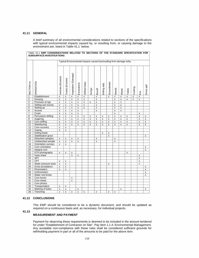
110
41.11 GENERAL
A brief summary of all environmental considerations related to sections of the specifications with typical environmental impacts caused by, or resulting from, or causing damage to the environment are, listed in Table 41.1 below.
Table 41.1 EMP CONSIDERATIONS RELATED TO SECTIONS OF THE STAND ARD SPECIFICATION FOR SUBSURFACE INVESTIGATIONS
Typical Environmental Impacts caused by/resulting from damage to/by
SE
CT
ION
no.
OP
ER
AT
ION
Veh
icle
s (E
rosi
on)
Tra
cks
(Ero
sion
)
Veg
etat
ion
(Dam
age)
Exc
avat
ions
Oil/
fuel
leak
s
Sum
ps
Run
off
Dril
ling
aids
Gro
undw
ater
Wee
ds
Was
te
Toi
lets
Coo
king
Fire
Gro
ut s
pill
1 Establishment x x x x x x x x x x x x 2 Housing x x x x x x x x x x x 3 Provision of rigs x x x x x x x x x 4 Setting out/ survey x x x x x x x x 5 Setting up x x x x x x x x 6 Access x x x x x x x 7 Crops x x x x x x 8 Percussion drilling x x x x x x x x x x x x x x 9 Augering x x x x x x x x x x x x x x 10 Core drilling x x x x x x x x x x x x x x 11 Washboring x x x x x x x x x x x x x x 12 Core recovery x x 13 Casing x x 14 Drilling fluids x x 15 Stabilisation grout x x 16 Disturbed samples x x x x x x 17 Undisturbed sample x x x x x x 18 Orientation surveys x x 19 Core orientation x 20 Integral core x 21 DTH photography x x x x 22 Vane shear x x x 23 SPT x 24 CPT x x x 25 Water pressure tests x x x x 26 Grout acceptance x x x 27 Piezometers x x x 28 Inclinometers x 29 Water rest levels x 30 Core boxes x 31 Core sheds x 32 Core photos 33 Transportation x x 34 Marking of holes x x x x x 35 Trenching x x x x x x x x
41.12 CONCLUSIONS
This EMP should be considered to be a dynamic document, and should be updated as required on a continuous basis and, as necessary, for individual projects.
41.13 MEASUREMENT AND PAYMENT Payment for observing these requirements is deemed to be included in the amount tendered for under “Establishment of Contractor on Site”, Pay Item 1.1.4: Environmental Management. Any avoidable non-compliance with these rules shall be considered sufficient grounds for withholding payment in part or all of the amounts to be paid for the above item.

111