Standard Specifications for Road and Bridge ConstructionStandard Specifications for Road and Bridge...
656
Standard Specifications for Road and Bridge Construction Prepared by NORTH DAKOTA DEPARTMENT OF TRANSPORTATION BISMARCK, NORTH DAKOTA www.dot.nd.gov DIRECTOR Francis G. Ziegler, P.E. DEPUTY DIRECTOR FOR ENGINEERING Grant Levi, P.E. Adopted October 2008 Volume 1 of 2
Transcript of Standard Specifications for Road and Bridge ConstructionStandard Specifications for Road and Bridge...

Standard Specificationsfor
Road and BridgeConstruction
Prepared by
NORTH DAKOTA DEPARTMENT OF TRANSPORTATIONBISMARCK, NORTH DAKOTA
www.dot.nd.gov
DIRECTORFrancis G. Ziegler, P.E.
DEPUTY DIRECTOR FOR ENGINEERINGGrant Levi, P.E.
Adopted October 2008
Volume 1 of 2

hjjk

II
NOTICE OF DISCLAIMER
Working titles having amasculine gender, such as workman, workmen, and foreman,andpronouns suchashe, his, andhimareutilized in theseSpecifications for the sakeofbrevity and are intended to refer to persons of either sex.
The North Dakota Department of Transportation (Department) makes the Road andBridge Construction Specifications available on an “as is” basis as a public service.
Under no circumstance does the Department warrant or certify the information to befree of errors or deficiencies of any kind. The Department specifically disclaims allwarranties, expressed or implied, including, but not limited to, the warranties of mer-chantability and fitness for a particular purpose.
The use of any of this information for work which is under contract with the Depart-ment, does not relieve the user from any obligations assumed by the contract, or fromcomplete and proper fulfillment of the terms of the contract, nor does it entitle the userto compensation for damages or loss which could be attributed to such use.
The information is subject to change by theDepartment. Anyone relying on this infor-mation should satisfy himself/herself as to themost current version. The user agrees toaccept all risks and consequence flowing formor related to the use, retention, distribu-tion, alteration, or deletion of this information. The Department will in no instance beliable for any loss of profit or other damage, including, but not limited to, special, in-cidental, consequential, or other damages, even if apprised of the likelihood of suchdamages.
III
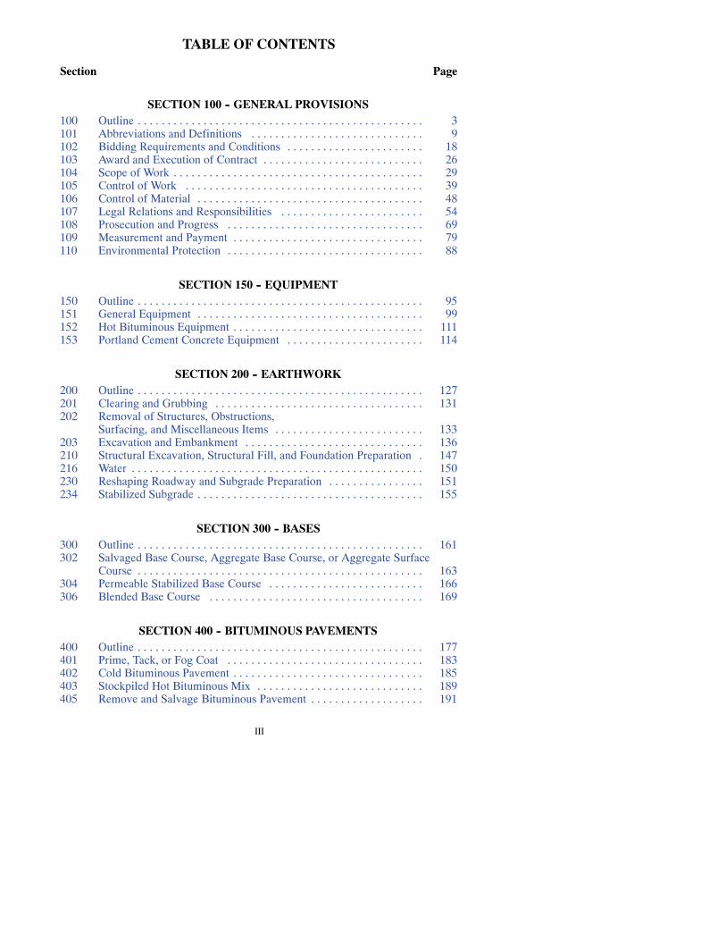
TABLE OF CONTENTS
Section Page
SECTION 100 -- GENERAL PROVISIONS100 Outline 3. . . . . . . . . . . . . . . . . . . . . . . . . . . . . . . . . . . . . . . . . . . . . . . .101 Abbreviations and Definitions 9. . . . . . . . . . . . . . . . . . . . . . . . . . . . .102 Bidding Requirements and Conditions 18. . . . . . . . . . . . . . . . . . . . . . .103 Award and Execution of Contract 26. . . . . . . . . . . . . . . . . . . . . . . . . . .104 Scope of Work 29. . . . . . . . . . . . . . . . . . . . . . . . . . . . . . . . . . . . . . . . . .105 Control of Work 39. . . . . . . . . . . . . . . . . . . . . . . . . . . . . . . . . . . . . . . .106 Control of Material 48. . . . . . . . . . . . . . . . . . . . . . . . . . . . . . . . . . . . . .107 Legal Relations and Responsibilities 54. . . . . . . . . . . . . . . . . . . . . . . .108 Prosecution and Progress 69. . . . . . . . . . . . . . . . . . . . . . . . . . . . . . . . .109 Measurement and Payment 79. . . . . . . . . . . . . . . . . . . . . . . . . . . . . . . .110 Environmental Protection 88. . . . . . . . . . . . . . . . . . . . . . . . . . . . . . . . .
SECTION 150 -- EQUIPMENT150 Outline 95. . . . . . . . . . . . . . . . . . . . . . . . . . . . . . . . . . . . . . . . . . . . . . . .151 General Equipment 99. . . . . . . . . . . . . . . . . . . . . . . . . . . . . . . . . . . . . .152 Hot Bituminous Equipment 111. . . . . . . . . . . . . . . . . . . . . . . . . . . . . . . .153 Portland Cement Concrete Equipment 114. . . . . . . . . . . . . . . . . . . . . . .
SECTION 200 -- EARTHWORK200 Outline 127. . . . . . . . . . . . . . . . . . . . . . . . . . . . . . . . . . . . . . . . . . . . . . . .201 Clearing and Grubbing 131. . . . . . . . . . . . . . . . . . . . . . . . . . . . . . . . . . .202 Removal of Structures, Obstructions,
Surfacing, and Miscellaneous Items 133. . . . . . . . . . . . . . . . . . . . . . . . .203 Excavation and Embankment 136. . . . . . . . . . . . . . . . . . . . . . . . . . . . . .210 Structural Excavation, Structural Fill, and Foundation Preparation 147.216 Water 150. . . . . . . . . . . . . . . . . . . . . . . . . . . . . . . . . . . . . . . . . . . . . . . . .230 Reshaping Roadway and Subgrade Preparation 151. . . . . . . . . . . . . . . .234 Stabilized Subgrade 155. . . . . . . . . . . . . . . . . . . . . . . . . . . . . . . . . . . . . .
SECTION 300 -- BASES300 Outline 161. . . . . . . . . . . . . . . . . . . . . . . . . . . . . . . . . . . . . . . . . . . . . . . .302 Salvaged Base Course, Aggregate Base Course, or Aggregate Surface
Course 163. . . . . . . . . . . . . . . . . . . . . . . . . . . . . . . . . . . . . . . . . . . . . . . .304 Permeable Stabilized Base Course 166. . . . . . . . . . . . . . . . . . . . . . . . . .306 Blended Base Course 169. . . . . . . . . . . . . . . . . . . . . . . . . . . . . . . . . . . .
SECTION 400 -- BITUMINOUS PAVEMENTS400 Outline 177. . . . . . . . . . . . . . . . . . . . . . . . . . . . . . . . . . . . . . . . . . . . . . . .401 Prime, Tack, or Fog Coat 183. . . . . . . . . . . . . . . . . . . . . . . . . . . . . . . . .402 Cold Bituminous Pavement 185. . . . . . . . . . . . . . . . . . . . . . . . . . . . . . . .403 Stockpiled Hot Bituminous Mix 189. . . . . . . . . . . . . . . . . . . . . . . . . . . .405 Remove and Salvage Bituminous Pavement 191. . . . . . . . . . . . . . . . . . .
IV
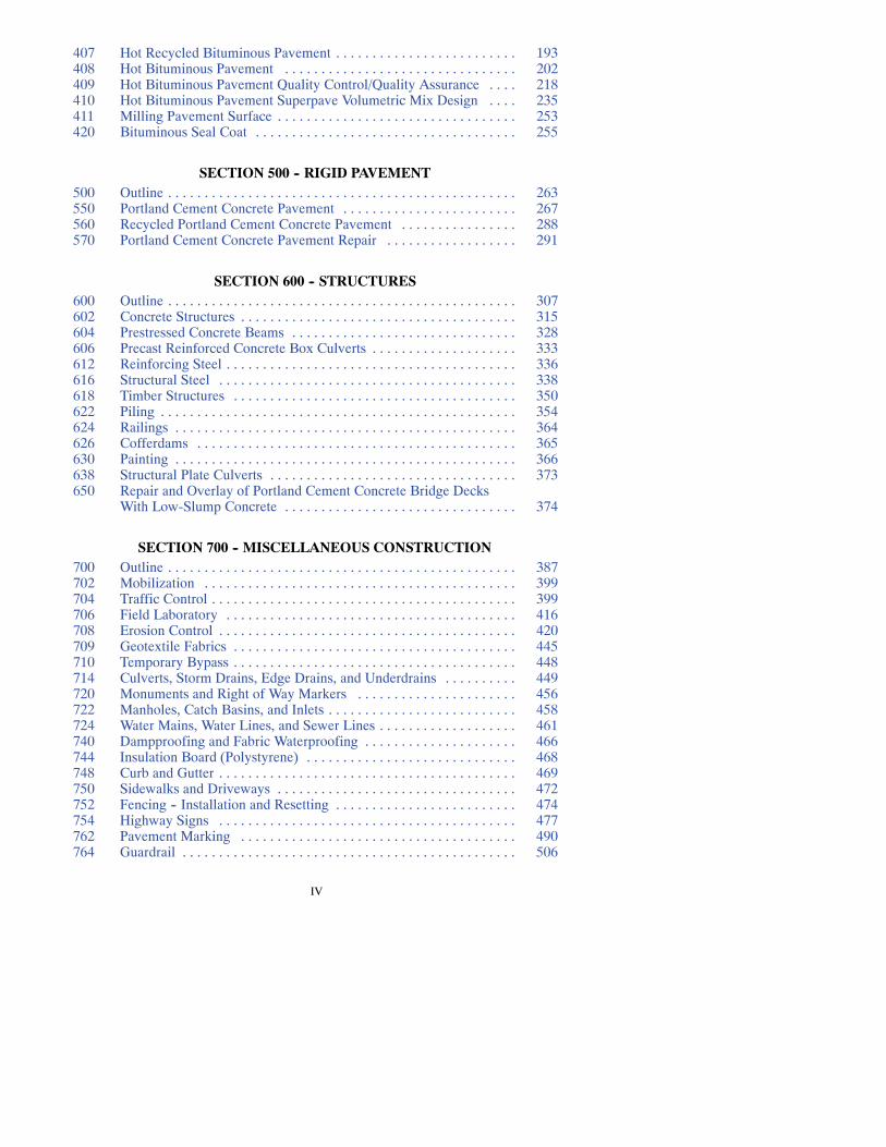
407 Hot Recycled Bituminous Pavement 193. . . . . . . . . . . . . . . . . . . . . . . . .408 Hot Bituminous Pavement 202. . . . . . . . . . . . . . . . . . . . . . . . . . . . . . . .409 Hot Bituminous Pavement Quality Control/Quality Assurance 218. . . .410 Hot Bituminous Pavement Superpave Volumetric Mix Design 235. . . .411 Milling Pavement Surface 253. . . . . . . . . . . . . . . . . . . . . . . . . . . . . . . . .420 Bituminous Seal Coat 255. . . . . . . . . . . . . . . . . . . . . . . . . . . . . . . . . . . .
SECTION 500 -- RIGID PAVEMENT500 Outline 263. . . . . . . . . . . . . . . . . . . . . . . . . . . . . . . . . . . . . . . . . . . . . . . .550 Portland Cement Concrete Pavement 267. . . . . . . . . . . . . . . . . . . . . . . .560 Recycled Portland Cement Concrete Pavement 288. . . . . . . . . . . . . . . .570 Portland Cement Concrete Pavement Repair 291. . . . . . . . . . . . . . . . . .
SECTION 600 -- STRUCTURES600 Outline 307. . . . . . . . . . . . . . . . . . . . . . . . . . . . . . . . . . . . . . . . . . . . . . . .602 Concrete Structures 315. . . . . . . . . . . . . . . . . . . . . . . . . . . . . . . . . . . . . .604 Prestressed Concrete Beams 328. . . . . . . . . . . . . . . . . . . . . . . . . . . . . . .606 Precast Reinforced Concrete Box Culverts 333. . . . . . . . . . . . . . . . . . . .612 Reinforcing Steel 336. . . . . . . . . . . . . . . . . . . . . . . . . . . . . . . . . . . . . . . .616 Structural Steel 338. . . . . . . . . . . . . . . . . . . . . . . . . . . . . . . . . . . . . . . . .618 Timber Structures 350. . . . . . . . . . . . . . . . . . . . . . . . . . . . . . . . . . . . . . .622 Piling 354. . . . . . . . . . . . . . . . . . . . . . . . . . . . . . . . . . . . . . . . . . . . . . . . .624 Railings 364. . . . . . . . . . . . . . . . . . . . . . . . . . . . . . . . . . . . . . . . . . . . . . .626 Cofferdams 365. . . . . . . . . . . . . . . . . . . . . . . . . . . . . . . . . . . . . . . . . . . .630 Painting 366. . . . . . . . . . . . . . . . . . . . . . . . . . . . . . . . . . . . . . . . . . . . . . .638 Structural Plate Culverts 373. . . . . . . . . . . . . . . . . . . . . . . . . . . . . . . . . .650 Repair and Overlay of Portland Cement Concrete Bridge Decks
With Low-Slump Concrete 374. . . . . . . . . . . . . . . . . . . . . . . . . . . . . . . .
SECTION 700 -- MISCELLANEOUS CONSTRUCTION700 Outline 387. . . . . . . . . . . . . . . . . . . . . . . . . . . . . . . . . . . . . . . . . . . . . . . .702 Mobilization 399. . . . . . . . . . . . . . . . . . . . . . . . . . . . . . . . . . . . . . . . . . .704 Traffic Control 399. . . . . . . . . . . . . . . . . . . . . . . . . . . . . . . . . . . . . . . . . .706 Field Laboratory 416. . . . . . . . . . . . . . . . . . . . . . . . . . . . . . . . . . . . . . . .708 Erosion Control 420. . . . . . . . . . . . . . . . . . . . . . . . . . . . . . . . . . . . . . . . .709 Geotextile Fabrics 445. . . . . . . . . . . . . . . . . . . . . . . . . . . . . . . . . . . . . . .710 Temporary Bypass 448. . . . . . . . . . . . . . . . . . . . . . . . . . . . . . . . . . . . . . .714 Culverts, Storm Drains, Edge Drains, and Underdrains 449. . . . . . . . . .720 Monuments and Right of Way Markers 456. . . . . . . . . . . . . . . . . . . . . .722 Manholes, Catch Basins, and Inlets 458. . . . . . . . . . . . . . . . . . . . . . . . . .724 Water Mains, Water Lines, and Sewer Lines 461. . . . . . . . . . . . . . . . . . .740 Dampproofing and Fabric Waterproofing 466. . . . . . . . . . . . . . . . . . . . .744 Insulation Board (Polystyrene) 468. . . . . . . . . . . . . . . . . . . . . . . . . . . . .748 Curb and Gutter 469. . . . . . . . . . . . . . . . . . . . . . . . . . . . . . . . . . . . . . . . .750 Sidewalks and Driveways 472. . . . . . . . . . . . . . . . . . . . . . . . . . . . . . . . .752 Fencing -- Installation and Resetting 474. . . . . . . . . . . . . . . . . . . . . . . . .754 Highway Signs 477. . . . . . . . . . . . . . . . . . . . . . . . . . . . . . . . . . . . . . . . .762 Pavement Marking 490. . . . . . . . . . . . . . . . . . . . . . . . . . . . . . . . . . . . . .764 Guardrail 506. . . . . . . . . . . . . . . . . . . . . . . . . . . . . . . . . . . . . . . . . . . . . .

V
766 Mailbox Assemblies 512. . . . . . . . . . . . . . . . . . . . . . . . . . . . . . . . . . . . .770 Highway Lighting See Vol. 2. . . . . . . . . . . . . . . . . . . . . . . . . . . . . . . . . . .772 Highway Traffic Signals See Vol. 2. . . . . . . . . . . . . . . . . . . . . . . . . . . . . .
SECTION 800 -- MATERIALS800 Outline 517. . . . . . . . . . . . . . . . . . . . . . . . . . . . . . . . . . . . . . . . . . . . . . . .801 General Statement 529. . . . . . . . . . . . . . . . . . . . . . . . . . . . . . . . . . . . . . .802 Portland Cement Concrete 529. . . . . . . . . . . . . . . . . . . . . . . . . . . . . . . .804 Cement and Lime 537. . . . . . . . . . . . . . . . . . . . . . . . . . . . . . . . . . . . . . .806 Grouts and Mortar 537. . . . . . . . . . . . . . . . . . . . . . . . . . . . . . . . . . . . . . .808 Concrete Admixtures 538. . . . . . . . . . . . . . . . . . . . . . . . . . . . . . . . . . . .810 Concrete Curing Materials 538. . . . . . . . . . . . . . . . . . . . . . . . . . . . . . . .812 Water 539. . . . . . . . . . . . . . . . . . . . . . . . . . . . . . . . . . . . . . . . . . . . . . . . .816 Aggregates 539. . . . . . . . . . . . . . . . . . . . . . . . . . . . . . . . . . . . . . . . . . . . .817 Salvaged Base Course 545. . . . . . . . . . . . . . . . . . . . . . . . . . . . . . . . . . . .818 Bituminous Materials 548. . . . . . . . . . . . . . . . . . . . . . . . . . . . . . . . . . . .820 Fly Ash 553. . . . . . . . . . . . . . . . . . . . . . . . . . . . . . . . . . . . . . . . . . . . . . .822 Penetrating Water Repellent 554. . . . . . . . . . . . . . . . . . . . . . . . . . . . . . .824 Dampproofing and Waterproofing 555. . . . . . . . . . . . . . . . . . . . . . . . . .826 Joint Materials 556. . . . . . . . . . . . . . . . . . . . . . . . . . . . . . . . . . . . . . . . . .830 Pipe 560. . . . . . . . . . . . . . . . . . . . . . . . . . . . . . . . . . . . . . . . . . . . . . . . . .834 Structural Steel and Related Materials 562. . . . . . . . . . . . . . . . . . . . . . .836 Reinforcing Steel 567. . . . . . . . . . . . . . . . . . . . . . . . . . . . . . . . . . . . . . . .840 Piling 569. . . . . . . . . . . . . . . . . . . . . . . . . . . . . . . . . . . . . . . . . . . . . . . . .844 Structural Timber, Lumber, and Hardware 570. . . . . . . . . . . . . . . . . . . .846 Preservatives and Pressure Treatment Processes for Timber 570. . . . . .848 Masonry Units and Brick 571. . . . . . . . . . . . . . . . . . . . . . . . . . . . . . . . .852 Paints, Oils, and Thinners 571. . . . . . . . . . . . . . . . . . . . . . . . . . . . . . . . .854 Galvanizing 571. . . . . . . . . . . . . . . . . . . . . . . . . . . . . . . . . . . . . . . . . . . .856 Erosion Control Blanket and Turf Reinforcement Mat 572. . . . . . . . . . .858 Geotextile Fabrics 575. . . . . . . . . . . . . . . . . . . . . . . . . . . . . . . . . . . . . . .860 Fence 576. . . . . . . . . . . . . . . . . . . . . . . . . . . . . . . . . . . . . . . . . . . . . . . . .862 Guardrail and Posts 577. . . . . . . . . . . . . . . . . . . . . . . . . . . . . . . . . . . . . .868 Insulation Board (Polystyrene) 581. . . . . . . . . . . . . . . . . . . . . . . . . . . . .880 Pavement Markings 581. . . . . . . . . . . . . . . . . . . . . . . . . . . . . . . . . . . . . .894 Highway Signs and Posts 597. . . . . . . . . . . . . . . . . . . . . . . . . . . . . . . . .895 Highway Lighting See Vol. 2. . . . . . . . . . . . . . . . . . . . . . . . . . . . . . . . . . .896 Highway Traffic Signals See Vol. 2. . . . . . . . . . . . . . . . . . . . . . . . . . . . . .

VI
1
SECTION 100GENERAL PROVISIONS

2

3
SECTION 101ABBREVIATIONS AND DEFINITIONS
101.01 ABBREVIATIONS
101.02 DEFINITIONS
SECTION 102BIDDING REQUIREMENTS AND CONDITIONS
102.01 PREQUALIFICATION OF BIDDERS
102.02 CONTRACTOR’S LICENSE
102.03 CONTENTS OF PROPOSAL FORMS
102.04 ISSUANCE OF PROPOSAL FORMS
102.05 INTERPRETATION OF QUANTITIES IN BID SCHEDULE
102.06 EXAMINATION OF PLANS, SPECIFICATIONS, SPECIAL PROVI-SIONS AND SITE OF WORK
102.07 PREPARATION OF PROPOSALS
102.08 IRREGULAR PROPOSALS
102.09 PROPOSAL GUARANTY
102.10 DELIVERY OF PROPOSALS
102.11 WITHDRAWAL OR REVISION OF PROPOSALS
102.12 PUBLIC OPENING OF PROPOSALS
102.13 DISQUALIFICATION OF BIDDERS
SECTION 103AWARD AND EXECUTION OF CONTRACT
103.01 CONSIDERATION OF PROPOSALS
103.02 AWARD OF CONTRACT
103.03 CANCELLATION OF AWARD
103.04 RETURN OF PROPOSAL GUARANTY
103.05 REQUIREMENT OF CONTRACT BOND
103.06 EXECUTION AND APPROVAL OF CONTRACT
103.07 FAILURE TO EXECUTE CONTRACT
103.08 ESCROW OF BID DOCUMENTATION
SECTION 104CONTRACT ADJUSTMENTS
104.01 INTENT OF CONTRACT

4
104.02 SUBLETTING OF CONTRACT
104.03 ALTERATION AND CHANGE OF PLANS OR CHARACTER OFWORK
A. Significant Changes in the Character of WorkB. Increased or Decreased QuantitiesC. Eliminated Items
104.04 DIFFERING SITE CONDITIONS
104.05 ADDITIONAL COMPENSATION FOR SUSPENSION OR DELAY OFWORK
104.06 CLAIM FOR EXTRA COMPENSATIONA. Notice of Intent to File a ClaimB. Submission of the ClaimC. Department’s Response to ClaimD. Conditions Precedent to Contractor’s Demand for Arbitration
104.07 CLAIMS AGAINST CONTRACTOR
104.08 VALUE ENGINEERING INCENTIVE
SECTION 105CONTROL OF WORK
105.01 GENERAL
105.02 CONTRACTOR REQUIREMENTS
105.03 COOPERATION WITH UTILITIES
105.04 COOPERATION BETWEEN CONTRACTORS
105.05 COORDINATION OF PLANS, STANDARD SPECIFICATIONS, SUP-PLEMENTAL SPECIFICATIONS, AND SPECIAL PROVISIONS
105.06 CHARACTER OF WORKERS, METHODS, AND EQUIPMENT
105.07 CONFORMITY WITH PLANS AND SPECIFICATIONS
105.08 PLANS AND WORKING DRAWINGS
105.09 AUTHORITY OF THE ENGINEER
105.10 CONSTRUCTION STAKING
105.11 DUTIES OF THE INSPECTOR
105.12 INSPECTION OF WORK
105.13 ACCEPTANCEA. GeneralB. Opening to TrafficC. Partial AcceptanceD. Final Acceptance
105.14 NO WAIVER OF LEGAL RIGHTS

5
105.15 FURNISHING RIGHT OF WAY
SECTION 106CONTROL OF MATERIAL
106.01 GENERAL METHODS OF MATERIAL ACCEPTANCE
106.02 LOCAL MINERAL AGGREGATE SOURCESA. GeneralB. State-Optioned DepositsC. State-Owned DepositsD. Private-Owned DepositsE. Aggregate Source Limitations
106.03 SAMPLES, TESTS, CITED SPECIFICATIONS
106.04 STORAGE OF MATERIALS
106.05 HANDLING MATERIALS
106.06 STOCKPILING AGGREGATE AND SALVAGED MATERIAL
106.07 RIGHTS IN AND USE OF MATERIAL FOUND IN THE WORK
106.08 DEPARTMENT FURNISHED MATERIAL
106.09 BUY AMERICAN PRODUCTS
106.10 CONVICT LABOR
106.11 QUALIFIED LABORATORIES AND TESTING PERSONNEL
SECTION 107LEGAL RELATIONS AND RESPONSIBILITIES
107.01 LAWS TO BE OBSERVED
107.02 PERMITS, LICENSES, AND TAXES
107.03 PATENTED DEVICES, MATERIALS, AND PROCESSES
107.04 HISTORICAL PRESERVATION RESPONSIBILITIES
107.05 RESPONSIBILITY TO THE PUBLICA. Maintaining Traffic
1. General2. Special Bypasses3. Maintenance of Traffic During Suspension of Work4. Maintenance Directed by the Engineer5. Parking of Equipment, Vehicles, and Stored Materials6. Urban Work
B. Haul Roads1. General2. Designation of Haul Roads3. Pre-Haul Inspection4. Materials

6
5. Use, Maintenance, and Restoration6. Method of Measurement7. Basis of Payment
C. Use of ExplosivesD. Protection and Restoration of the PropertyE. Responsibility for Damage ClaimsF. Personal Liability of Public Officials
107.06 RAILWAY HIGHWAY PROVISIONSA. IndemnificationB. Railway ProtectionC. Railway Protection Insurance
1. General Liability2. Policy
D. Railway Public Liability InsuranceE. General Insurance RequirementsF. Basis of Payment
107.07 PUBLIC LIABILITY AND PROPERTY DAMAGE INSURANCEA. Insurance RequirementsB. General RequirementsC. Subcontractor
107.08 HAZARDOUS MATERIAL
107.09 CIVIL RIGHTS
107.10 INERT WASTE DISPOSAL
SECTION 108PROSECUTION AND PROGRESS
108.01 PROSECUTION AND PROGRESS
108.02 NOTICE TO PROCEED
108.03 LIMITATION OF OPERATIONS
108.04 DETERMINATION AND EXTENSION OF CONTRACT TIMEA. Contract TimeB. Working Day ContractsC. Completion Date ContractsD. Increased WorkE. Delayed Delivery of MaterialsF. Other DelaysG. Request for Additional TimeH. Conversion of Working Day to Calendar DayI. Weekly Statement of Time ChargesJ. Failure to Complete on TimeK. Unsatisfactory ProgressL. Incentive/Disincentive Provisions
108.05 DEFAULT AND TERMINATION OF CONTRACT
108.06 TERMINATION OF CONTRACT

7
SECTION 109MEASUREMENT AND PAYMENT
109.01 MEASUREMENT OF QUANTITIES
109.02 SCOPE OF PAYMENT
109.03 FREIGHT RATES
109.04 FORCE ACCOUNT
A. LaborB. MaterialsC. EquipmentD. MiscellaneousE. SubcontractingF. Authority of EngineerG. Daily RecordsH. StatementsI. CompensationJ. Specialty WorkK. Payment
109.05 PARTIAL PAYMENT
A. Partial PaymentB. Prompt PaymentC. RetainageD. No Circumvention
109.06 PAYMENT FOR MATERIAL ON HAND
109.07 COMPENSATION FOR ALTERED QUANTITIES
109.08 ACCEPTANCE AND FINAL PAYMENT
109.09 CONVERSION TO METRIC SYSTEM
SECTION 110ENVIRONMENTAL PROTECTION
110.01 DESCRIPTION
110.02 MATERIALS
110.03 PRECONSTRUCTION CONFERENCE
110.04 STORMWATER PERMITS
110.05 OPERATIONAL CONTROLS
A. Work Areas
110.06 EROSION CONTROLS
110.07 METHOD OF MEASUREMENT AND PAYMENT

8

9
101.01
SECTION 101ABBREVIATIONS AND DEFINITIONS
Wherever the following abbreviations or terms are used in these Specifications, thePlans, or other Contract documents, their meaning shall be as follows:
101.01 ABBREVIATIONS.
AAN American Association of NurserymenAAR Association of American RailroadsAASHTO American Association of State Highway and Transportation OfficialsAC Asphaltic CementACI American Concrete InstituteADA Americans with Disabilities ActAGC Associated General Contractors of AmericaAIA American Institute of ArchitectsAISI American Iron and Steel InstituteANSI American National Standards Institute, Inc.ARA American Railway AssociationAREMA American Railway Engineering and Maintenance-of-Way AssociationARTBA American Road and Transportation Builders AssociationASCE American Society of Civil EngineersASLA American Society of Landscape ArchitectsASTM American Society for Testing and MaterialsATSSA American Traffic Safety Services AssociationAWPA American Wood Preservers AssociationAWWA American Water Works AssociationAWS American Welding SocietyBIA Bureau of Indian AffairsBMP Best Management PracticesCADD Computer-Aided Drafting DesignCARS Construction Automated Records SystemCOE Corps of EngineersCFR Code of Federal RegulationsCMC County Major CollectorCPM Critical Path MethodCRS County Rural SocietyCRSI Concrete Reinforcing Steel InstituteDBE Disadvantaged Business EnterpriseEEO Equal Employment OpportunityESAL Equivalent Single Axle LoadEPA Environmental Protection Agency

10
101.01
FAA Federal Aviation AdministrationFHWA Federal Highway Administration, Department of TransportationFSS Federal Specifications and Standards, General Services AdministrationMUTCD Manual on Uniform Traffic Control DevicesNDCC North Dakota Century CodeNDDOT North Dakota Department of TransportationNEMA National Electric Manufacturer’s AssociationNEPA National Environmental Policy ActNHTSA National Highway Traffic Safety AdministrationOSHA Occupational Safety and Health AdministrationPCA Portland Cement AssociationPCC Portland Cement ConcretePCI Prestressed Concrete InstitutePVC Polyvinylchloride -- PVC PipeQA Quality AssuranceQC Quality ControlSAE Society of Automotive EngineersSG Specific GravitySHPO State Historic Preservation OfficerSSPC Steel Structures Painting CouncilUL Underwriters Laboratory, Inc.USFWS U.S. Fish and Wildlife ServiceVMA Voids in Mineral Aggregate
101.02 DEFINITIONS.
Act of God.An unforeseeable act, event, or happening resulting from natural causessuch as earthquake, tornado, or other cataclysmic phenomena.
Addendum.Contract revisions developed after advertisement of bids and before bidopening.
Advertisement. The public announcement inviting bids for work to be performed ormaterials to be furnished.
Award. The Department’s acceptance of a Proposal.
Base Course.The layer or layers of specified or selectedmaterial placed on a subbaseor subgrade to support a surface course.
Bidder. An individual, or legal entity submitting a Proposal.
Bid Documents. All writings, working papers, computer printouts, charts, and allother data compilationwhich contain or reflect information, data, or calculations usedby theBidder to determine the bidproposal submitted, includingbut not limited toma-terial relating to the determination and application of:
equipment ratesoverhead rates and related time scheduleslabor ratesefficiency or productivity factors

11
101.02
arithmetic extensionsSubcontractor and material supplier quotations
Manuals which are standard to the industrymay be included in the bid documentationby reference and will show the name and date of the publication and the Publisher.
Bid Opening. The public opening of bid proposals submitted at the prescribed timeand date meeting Department requirements and procedures.
Bid Schedule (also knownas the Schedule of Items).A list of the bid items and esti-mated quantities in the Proposal.
Bridge. A single-span or multiple-span structure including supports, erected over adepressionorobstructionsuchaswater, highway, or railway; andhavinga trackorpas-sageway for carrying traffic or other moving loads; and having a length measuredalong the center of roadway of more than 20 feet between undercopings of abutmentsor extreme ends of openings for multiple boxes.
Bridge Length.The greater dimension of a structuremeasured along the center of theroadway between backs of abutment walls or between ends of bridge deck.
Bridge Roadway Width. The clear width of a structure measured at right angles tothecenter of the roadwaybetween thebottomof curbsor, if curbsarenotused,betweenthe inner faces of parapet or railing.
Calendar Day. Every day shown on the calendar including Sundays and holidays. Aday begins and ends at midnight.
Change Order. A written order from the Department to the Contractor, coveringchanges in Contract documents, for ExtraWork within the scope of the Contract, andfor establishing the basis of payment or time adjustments for work affected by thechanges. This may include, for example, additional items of work or an adjustment inunit prices.When thework involved necessitates an adjustment in the Contract terms,it must be signed by the Contractor and Engineer, or his representative, before it be-comeseffective.AChangeOrder signedbyall parties to theContract is a supplementalagreement.
Claim. A written request or demand for something due or believed to be due.
Clue.Apotential sourceof aggregatematerial identified in theProposal and, if used, isconsidered a Contractor-furnished material source.
Completion.Theproject is completewhen allwork under theContract has been satis-factorily completed and is open to traffic or available for use by the traveling public;and the Project is in condition for final acceptance.
Conformity. Compliance with reasonable and customary manufacturing and con-struction toleranceswhereworking tolerances are not specified.Whereworking toler-ances are specified, conformity means compliance with such tolerances.
Contract. The written agreement between the Department and the Contractor settingforth the obligations of the parties for the performance of the prescribed work.
The Contract includes: the Proposal, Contract Form and Contract Bond, Specifica-tions, Supplemental Specifications, Special Provisions, Standard Drawings, general

12
101.02
anddetailedPlans,workdrawings, anyChangeOrdersandSupplementalAgreementsrequired to complete the work and authorized extensions of time.
Contract Bond. The security, executed by the Contractor and the Surety or Sureties,furnished to the Department to guarantee complete execution of the Contract and allSupplementalAgreements and thepayment of all legal debts pertaining to project con-struction.
Contract Item (Pay Item).Aspecificunit ofwork forwhichaprice isprovided in theContract.
Contract Time.Thenumberofworkdays, calendardays, acombinationof the two,ora final calendar date allowed for completion of the Contract including authorized timeextensions.
Contractor. The individual, or legal entity contracting with the Department for per-formance of prescribed work.
County. The jurisdiction or jurisdictions in which the work is located.
Critical Path Method. An electronic system of planning, scheduling, and controlwhich combines all relevant information into a single master plan, permitting theestablishment of the optimum sequence and duration of operations; utilizing an arrowdiagramdrawntoshowthe inerconnected individual tasks involved inconstructing theProject.
Culvert.Any structure under the roadwaywith a clear opening of 20 feet or lessmeas-ured along the center of the roadway.
Department.TheNorth DakotaDepartmentofTransportation (NDDOT)or its repre-sentatives.
Digital Identification. A unique number issued by the Department and assigned toContractors for security and identification purposes.
Director. The Director of the North Dakota Department of Transportation acting di-rectly or through authorized representatives.
Divided Highway.A highway with separated roadways for traffic in opposite direc-tions.
Driving Lane.The portion of the highway, excluding shoulders, normally used to ac-commodate the movement of vehicular traffic.
Employee.Any person working on the Project covered by the Contract who is underthe direction or control of, or receives compensation from the Contractor or Subcon-tractor.
Engineer. The Deputy Director for Engineering of the Department, acting directly orthrough an authorized representative who is responsible for engineering supervisionof construction.
Equipment. All machinery, tools, apparatus, and supplies necessary for the upkeep,maintenance, construction, and completion of the Project.

13
101.02
Expressway.Adivided arterial highway for through trafficwith full or partial controlof access and generally with grade separations at intersections.
Extra Work.Work not provided for in the Contract but considered essential by theEngineer for satisfactory completion of the Contract within its intended scope.
Extra Work Order. A Change Order for the performance of work or furnishing ofmaterials involving Extra Work at agreed prices or on a Force Account basis.
Federal-Aid Project.AProjectwhich is constructedentirelyor partiallywithFederalFunds.
Field Engineer.An authorized person who is in charge of a Project and reports to theEngineer.
Fog Coat.Athinapplicationofbitumenapplied to thepavement surface,withorwith-out a sand coating.
Force Account.Payment for extrawork on the basis of actual costs plus approved ad-ditives.
FracturedMaterial. Aggregate crushed to a smaller size from a larger size. (i.e. ag-gregate retained on a 5/8 inch sieve crushed to produce aggregate of 1/2 inch or less insize.)
Freeway. An expressway with full control of access.
Frontage Street or Road.Alocal streetor road locatedalongsideahighway for serv-ice to abutting property, adjacent areas and for control of access.
Geosynthetic. A product manufactured from a polymeric material used with soil,rock, earth, or other geotechnical engineering-related material as an integral part of aman-made project, structure, or system.
Geotextile. A permeable geosynthetic made of textile materials, ie: separation,drainage, riprap, and reinforcement fabrics.
Geogrid. A geosynthetic formed by a regular network of integrally connectedelements with apertures greater than 1/4 inch to allow interlocking with surroundingsoil, rock, earth, and other surrounding materials to primarily function asreinforcement.
Grade Separation.Acrossingof twohighways, or a highwayanda railroad, at differ-ent levels.
Highway, Street, or Road.A general term indicating a public way used by vehiclesand pedestrians. Includes entire area within the Right of Way.
Holidays. State of North Dakota holidays are as follows:
Every Sunday.The first day of January, which is New Year’s Day.The third Monday of January, which is Martin Luther King Day.

14
101.02
The third Monday of February, which is President’s Day.The Friday just before Easter Sunday and commonly known as Good Friday.The last Monday in May, which is Memorial Day.The fourthdayof July,which is the anniversaryof theDeclarationof Independence.The first Monday in September, which is Labor Day.The eleventh day of November, which is Veteran’s Day.The fourth Thursday in November, which is Thanksgiving Day.The twenty-fifth of December, which is Christmas Day.Every day appointed by thePresident of theUnitedStates or by theGovernor of thisState as a public holiday.
When a holiday falls on a Saturday, the precedingFriday shall be the holiday; or,whena holiday falls on a Sunday, the following Monday shall be the holiday.
The twenty-fourth ofDecember, ChristmasEve day,will be a half-dayholidaywhen itfalls on a Monday, Tuesday, Wednesday, and Thursday. State offices will close at12 noon that day.
Incentive/Disincentive Provisions. An adjustment to the Contract price of a prede-termined amount for each day the work is completed ahead of or behind the specifiedmilestone, phase, or Contract completion dates.
Inspector. The Engineer’s authorized representative assigned to make detailed in-spections of Contract performance.
Invitation for Bids. The advertisement for Proposals for work or materials onwhichbids are requested. The advertisement will indicate, with reasonable accuracy thequantity and locationofwork tobeperformed, the character andquantityofmaterial tobe furnished, and the time and place of the opening of Proposals.
Laboratory.The testing laboratory of the Department or any other testing laboratorydesignated by the Engineer.
Major and Minor Contract Items.Amajor item is anyContract itemhaving aCon-tract value in excess of 5 percent of the total original Contract amount. All other itemsare minor items.
Minor items in the original Proposal shall becomemajor items when the total cost in-creases to at least 5 percent of the total original Contract amount.
Materially UnbalancedBid.Abid inwhich there is a reasonable doubt that award tothe Bidder submitting the mathematically unbalanced bid will result in the lowestultimate cost to the Department.
Materials. Any substances specified for use in constructing the Project.
Mathematically Unbalanced Bid. A bid containing lump sum or unit bid itemswhich do not reflect reasonable actual costs plus a reasonable proportionate share ofthe Bidder’s anticipated profit, overhead costs, and other indirect costs, which he/sheanticipates for the performance of the items in question.
Median. The portion of a divided highway separating the traveled ways.
MGal. 1,000 gallons.

15
101.02
Notice to Bidders.A notice issued by the Department of projects available for bid inan upcoming Bid Opening.
Notice to Proceed.Awritten notice to the Contractor to begin the Contract work; or,in lieu of such written notice, the delivery of the executed Contract documents to theContractor will serve as “notice to proceed.”
Pavement Structure. The combination of subbase, base course, and surface courseplaced on a subgrade to support and distribute the traffic load to the roadbed.
Plans.TheContract drawings showing location, character, and dimensions of the pre-scribed work including layouts, profiles, cross sections, and other details.
Prequalified Bidder. A Bidder who has submitted evidence satisfying the Depart-ment as to the Bidder’s qualifications based on integrity, responsibility, and compe-tence relative to the type and size of the contemplated Projects, and has receivedwrit-ten authorization to bid from the Department.
Prequalification Forms. The specified forms on which required information is fur-nished concerning the Bidder’s ability to perform and finance the work.
Prime Coat.A surface application of bitumen or other approvedmaterial to coat andbind the aggregate base.
Profile.A charted line indicating elevation grades and distances and usually depth ofcut and height of fill for excavation andgradingwork; taken along a centerline or otherdesignated line. A side view, as distinct from a plan or overhead view.
Project.The specific section of highwayonwhich construction is to be performedun-der the Contract.
Proposal. (Commonly referred to asBid) TheBidder’s offer onDepartment forms, toperform the work at the prices quoted.
Proposal Form. (Commonly referred to as Proposal) The prescribed forms onwhichthe Department requires bids to be prepared and submitted for the work.
Proposal Guaranty.The security furnished toguarantee theBidderwill enter into theContract if the Proposal is accepted.
Responsive Bid. A bid which meets all requirements of the “Invitation for Bids.”
Responsible Bidder. A Bidder who has met all of the Department’s prequalificationrequirement and actually submits a bid on a project.
Right of Way.Ageneral termdenoting land, property, or interest therein, acquired foror devoted to a highway.
Roadbed. The graded portion of a highway, within top and side slopes, prepared as afoundation for the pavement structure and shoulder.
Roadside.The area adjoining the outer edge of the roadway. Extensive areas betweenthe roadways of a divided highway may also be considered roadside.
16
101.02
Roadway. The portion of a highway including shoulders for vehicular use.
Shop Drawings. Incidental drawings furnished by the Contractor illustrating how aspecific portion of the work shall be fabricated or installed.
Shoulder.Theportionof the roadwayadjacent to the traveledway for accommodationof stopped vehicles for emergency use and for lateral support of base and surfacecourses.
Sidewalk. A traveled pathway paralleling a highway, road, or street intendedexclusively for pedestrian use.
Sieve. U.S.A. Standard Sieve, as defined in AASHTO M 92. Percent passing sievesizes is by weight.
Special Provisions.Additions and revisions to theStandard andSupplemental Speci-fications covering special conditions on an individual project.
Specialty Item. Item ofwork that requires specialized knowledge, abilities, or equip-ment not ordinarily required with the major type of work specified in the Contract.
Specifications. Compilation of Special Provisions and Standard and SupplementalSpecifications for performance of prescribed work.
Specified Completion Date. The date on which the Contract work is specified to becompleted.
Stabilization.Themodification of soils or aggregates by incorporatingmaterials thatincreases load-bearingcapacity, firmness, or resistance toweatheringordisplacement.
Standard Details.Anapproved set of drawings showing standarddetails of construc-tion and materials.
Standard Specifications.Abook of Specifications approved for general applicationand repetitive use.
State. The State of North Dakota acting through its authorized representative.
State Aid Project. A Project which is constructed entirely with State Funds or Stateand local subdivision funds.
Station.Whenused as a definition or termofmeasurement, a station is 100 linear feet.
Structures. Bridges, culverts, catch basins, drop inlets, retaining walls, cribbing,manholes, endwalls, buildings, sewers, service pipes, underdrains, foundation drains,and similar features which may be encountered in the work.
Subcontractor.Anindividual, or legal entitywithwhomtheContractor subletspartofthe Contract.
Subbase. The layers of specified or selected material of designated thickness placedon a subgrade to support a base course.
Subgrade.The top surface of an embankment or cut section on a graded roadway. It isthe foundation for the subbase, base, and surface course.

17
101.02
Substantial Completion.AProject is substantially complete when it is open for safeand convenient use by the traveling public, and all necessary safety features are inplace; or, if not to be opened to traffic, when it is ready for the subsequent Project.
Substructure.All of the structure below the bearings of simple and continuous spans,skewbacks of arches and tops of footings of rigid frames, including the backwalls,wingwalls and wing protection railings.
Superintendent.TheContractor’s authorized representative in responsible charge ofthe work.
Superstructure. The entire structure except the substructure.
Supplemental Agreement.Awritten agreement for the performance of work whichis beyond the scope of the original Contract but which the Department elects to per-form in conjunction with the existing Contract.
Supplemental Specifications. Approved additions and revisions to the StandardSpecifications.
Surcharge.Additional fill material above the proposed grade line for the purpose ofadding weight.
Surety.The legal entity or individual, other than the Contractor, executing a ProposalGuaranty.
Surface Course. One or more layers of a pavement structure designed to accommo-date the traffic load; the top layer ofwhich resists skiddingand traffic abrasion.The toplayer is sometimes called “Wearing Course.”
Tack Coat.An application of bitumen to an existing asphalt surface to provide bondwith the next course.
Titles (or Headings). The titles or headings of the Sections and Subsections in thisbookare for referenceonly and shall havenobearingon the interpretationof specifica-tions.
Traveled Way.Theportionof the roadway for themovement of vehicles, exclusiveofshoulders and auxiliary lanes.
Unbalanced Bid. A bid that does not reflect the true cost of providing the material,equipment, and labor required to complete the item of work. (See “Materially Unbal-anced Bid” and “Mathematically Unbalanced Bid.”)
Variable Costs.Costs that change in relation to the activity andwork being performed.
Work. The furnishing of all labor, materials, equipment, and incidentals necessary tocomplete the Project according to all duties and obligations imposed by the Contract.
Working Day. A calendar day on which weather and other conditions not under theContractor’s control does not prevent construction operations from proceeding withthe normalworking force engaged in performing the controlling itemor items ofworkwhich would be in progress at that time.

18
102.02
Work Drawings. Supplemental design sheets or similar data which the Contractor isrequired to furnish such as shop drawings, product data sheets, erection plans, fal-sework plans, framework plans, cofferdam plans, and bending diagrams for reinforc-ing steel.
Work Order.Awritten order, signed by the Engineer, of a Contractual status requir-ing performance by the Contractor without negotiation.
Written Permission of the Engineer. A letter signed by the Engineer granting spe-cificpermissionandoutlining limitationsof thepermission.When these specificationsindicate thatwork shall be “required, requested, directed, authorized, ordered, permit-ted, suspended, approved, accepted, or rejected,” it shall be understood that these ex-pressions and others similar to them are followed by the phrase, “by the Engineer.”
SECTION 102BIDDING REQUIREMENTS AND CONDITIONS
102.01 PREQUALIFICATION OF BIDDERS.
Only prequalified Bidders will be allowed to bid on any Project. Evidence consists ofdetailed information regarding the Bidder’s finances, organization, equipment, andprevious experience, provided on standard forms furnished by the Department. Theprequalification forms shall be submittednot less than7daysbefore the bid opening inwhich the Bidder desires to bid, and at such additional times as the Director may re-quest or the Bidder elect. The prequalification shall be in force for the time periodspecified in the Department’s written authorization.
TheDirector reserves the right to check any or all statements submitted by the Bidder,and to obtain additional pertinent information from other sources. The Departmentreserves the right to disqualify a prospective Bidder for any reasons stated in Section102.13.
102.02 CONTRACTOR’S LICENSE.
ABidder is not required to have aContractor’s license from the State ofNorth Dakotato bid on a Project, however, a Contract will not be awarded until the Contractor ob-tains an appropriate North Dakota Contractor’s license.
102.03 CONTENTS OF PROPOSAL FORMS.
The Proposal Form will show the location and description of the contemplated con-struction, the estimate of the various quantities, the types of work to be performed ormaterials to be furnished, and the schedule of items for which Unit Bid Prices are in-vited. TheProposal Formwill state the time inwhich theworkmust be completed; andthe date, time, and place for opening of Proposals. The Proposal formwill also include

19
102.06
any Special Provisions or requirements which vary from or are not contained in theStandard Specifications.
All papers bound with or attached to the Proposal Form are considered a part of theProposal andmust not be detachedor alteredwhen theProposal is submitted. TheBid-der may attach a computer-printed bid schedule according to Section 102.07 C.2.
The Plans, Specifications, other documents designated in the Proposal Form will beconsidered a part of the Proposal whether attached or not.
The prospective Bidder shall pay the amount stated in the Notice to Contractors foreach copy of the Proposal Form and each set of Plans obtained from the Department.
102.04 ISSUANCE OF PROPOSAL FORMS.
Proposal Forms will be issued in accordance with the Advertisement for Bids.
102.05 INTERPRETATION OF QUANTITIES IN BID SCHEDULE.
The quantities appearing in the bid schedule are estimates prepared for comparison ofbids. Paymentwill bemade for actual quantities ofwork performed and accepted orma-terials furnished according to theContract. The estimated quantities ofwork andmateri-als may be increased, decreased, or pay items may be eliminated in their entirety.
102.06 EXAMINATION OF PLANS, SPECIFICATIONS, SPECIALPROVISIONS, AND SITE OF WORK.
TheBidder is to examine the site of the proposedwork, the Proposal, Plans, Specifica-tions, Supplemental Specifications, Special Provisions, and all other Contract formsbefore submitting a Proposal. The Bidder is responsible for all site conditions thatshouldhavebeendiscoveredwith aBidder site investigation.The submissionof apro-posal will be considered conclusive evidence that the Bidder is satisfied with the con-ditions to be encountered in performing thework and as to the requirements of the pro-posed Contract.
Boring logs and other records of subsurface investigations are available for inspectionby Bidders. It is made available so all Bidders have access to identical subsurface in-formation available to the Department, and is not intended as a substitute for personalinvestigation, interpretations, and judgment of the Bidders. This availability shall notrelieve the Bidder of the responsibility stated in the preceding paragraph. TheDepart-mentwill notbeboundbyanystatementor representationconcerningconditionsmadeby anyof its employees or agents before the execution of theContract, unless includedin the Proposal Form, Plans, Specifications, Supplemental Specifications, SpecialProvisions, or related Contract forms.
Any explanation desired by a Bidder regarding the meaning or interpretation of theProposal Form, Plans, Specifications, etc., must be requested from the Central Con-struction Office in adequate time to allow a reply to reach all Bidders before submis-sion of their Bids. Interpretations will be made by addendum and will be furnished toall prospective Bidders by either certified letter, Facsimile (FAX), or other electronictransmission before the time set for opening of Bids. Oral explanations or instructionsgiven before the bid opening will not be binding.

20
102.07
102.07 PREPARATION OF PROPOSALS.
A. General. The Bidder shall prepare the Proposal Form furnished by the Depart-ment utilizing one of the following methods:
1. Electronic bid on the internet using Bid Express, as specified below.
2. Electronic bid on a3-1/2 inch computer diskette or compact disc (hereinafterdiskette) with accompanying printout. The printout can be the Bidder’sProposal generated from Expedite software or the paper Proposal Formfurnished by the Department.
3. Paper bid on the Proposal Form furnished by the Department.
Any and all Department addenda to the Proposal shall be a part of the Bidder’sProposal.
TheBidder shall filewith theDepartmentaproperlyexecutedblanketbidbond,orshall submit an individual bid bond or certified checkwith the proposal, as speci-fied in Section 102.09 of the Standard Specifications. To be eligible to submitelectronic bids on the internet, the Bidder shall have a properly executed annualbid bond on file with the Department.
If discrepancies are foundbetweenproposals submittedby the sameBidder indif-ferent media, hand prepared paper bids shall govern over electronic printouts,electronic printouts shall govern over diskettes, and diskettes shall govern overelectronic bids submitted over the internet.
The Department will provide bidding information, Plans, proposal forms,addenda and other documents on theDepartment’sWeb site. Bidders shall checkthe Department’s Web site for addenda prior to submitting a bidders proposal.The Department will post all addenda no later than 4:00 p.m. Central Time twodays before the bid opening.An exception to this timeframe is thewithdrawal ofa project from the bid opening. Bidders shall acknowledge the receipt of all ad-dendumsasdesignated in theproposal form.Electronic bid files (Expedite files)are provided through the Bid Express on-line bidding exchange athttp://www.bidx.com/ and theDepartment’sWeb site at http://www.dot.nd.gov/ .Bidders utilizing Expedite shall ensure they have downloaded any addenda filesin regards to theExpedite electronic bid files, prior to submitting their final bid. Ifusing theExpedite bid files, bidders shall check either theBidExpressWeb site orthe Department’s Web site after 5:00 p.m. Central Time two days before the bidopening, to ensure that all addenda files for the Expedite files have beendownloaded before submitting the final bid.
Interested parties can subscribe to theBidExpress on-line bidding exchange by fol-lowing the instructions provided at the www.bidx.comWeb site or by contacting:
Info Tech Inc.5700 SW 34th Street, Suite 1235Gainesville, FL 32608-5371email: mailto:[email protected]
When an item on the Bid Schedule allows a choice of alternates, the Bidder shallindicate the choice for that particular item.
21
102.07 C
Proposals submitted by (1) an individual must be signed by that individual, (2) apartnership,must be signed by a partner, or (3) a corporationmust be signed by anofficer of the corporation with the officer’s title. Proposals submitted by a jointventure must be signed by a legally qualified representative of each of the partiesto the joint venture.AProposalmaybeexecuted for an individual, a legal entity, ora jointventurebyanyonehavingapowerof attorney, providedacopyof thepowerof attorney is attached to the proposal or is previously filed with the Department.
Properly execute the Proposal. Proposal not submitted via the internet shall havethe required signatures, in ink, in the space provided on the Proposal Form. Ifsubmitting a diskettewith accompanying printout, theBidder shall execute eitherthe Department-furnished paper Proposal Form or the Expedite-generatedBidder’s Proposal.
ABidder may submit bids onmore Projects than they desire to accept. Each suchbid proposal must be covered by a Proposal guarantee. The Bidder may indicatethe total work desired and the Director will determine which of the low bids willbe accepted within the Bidder’s indicated bid limitations. This limitation will ap-ply only to Projects onwhich theBidLimitation Section in the Proposal Formhasbeen completed by the Bidder.
B. Combination (Tied) Proposals. Proposal Forms may be issued for Projects incombination or separately, so bidsmay be submitted either on the combination oron separate units of the combination. The Department reserves the right to makeawards on combination bids or separate bids to the advantage of the Department.Combination bids, other than those specified, will not be considered. SeparateContracts will be written for each Project included in the combination.
C. Electronic Bidding on the Internet. Prior to submitting electronic bids over theInternet, the Bidder shall have a digital identification (ID) issued by the Depart-ment, on file with Info Tech Inc. and enabled by Info Tech Inc. Using this digitalID shall constitute the Bidder’s signature for proper execution of the Proposal.
1. Download the EBS files, DBE bin files and any addendums from the BidExpress or Department’s Web site.
2. Use Expedite software to generate and prepare the Bidder’s Proposal.
a. Provideaunit price for eachbid item, except asnot required in thecaseofalternate bid items. Follow the software instructions and review the helpscreens provided on theBid ExpressWeb site to assure that the scheduleof items is prepared properly.
3. Submit the bid according to the requirements of the Expedite software andthe Bid ExpressWeb site. Bidders should not submit a bid on a diskette withaccompanying printout or a paper bid, when submitting Internet bids. If thebidder does submit a bid on a diskettewith accompanying printout or a paperbid in addition to the internet submittal, the Department will disregard theInternet bid.
The Department will consider bids submitted over the Internet as accepted, at thetime and date specified in theNotice toBidders and not before such time anddate.
22
102.07 D
D. Electronic Bidding on a Diskette With Accompanying Printout.
1 Download the EBS files, DBE bin files and any addendums from the BidExpress or Department’s Web site.
2 Use Expedite software to generate and prepare the Bidder’s Proposal.
a. Provideaunit price for eachbid item, except asnot required in thecaseofalternate bid items. Follow the software instructions and review the helpscreens provided on theBid ExpressWeb site to assure that the scheduleof items is prepared properly.
3. Each diskette shall be labeled with the Bidder’s name, the Department-assigned Bidder-identification code, and a list of the proposal numbersincluded on that diskette, as indicated in the following example:
Bidder NameBidder IDProposals: 1, 12, 14, 16, & 22
a. If bidding onmore than one proposal in the bid opening, the Biddermayinclude all proposals for that bid openingononediskette.However, onlysubmitted proposals (with no incomplete or extraneous files) may be onthe diskette.
The accompanying printout shall be prepared in accordance with 102.07 E.1a.
E. Preparation of Bid Schedule.
1. Paper Bid.TheBidder shall enter a unit price in numerals on the Bid Sched-ule for each bid item, except as not required in the case of alternate bid items.The Bidder shall enter the product of each unit price and respective quantity.The sum of the products (Total Sum Bid) shall be entered where indicated.
a. Computer-Printed Bid Schedule. The Bidder may substitute acomputer-printed spreadsheet bid schedule for the Bid Schedule foundin theProposalFrom.The substitute schedule shall be attached to the lastpage of the Bid Schedule in the bound Bidder’s Proposal Form.
The computer-printed bid schedule shall be a printout generated by thecurrent version of Expedite, used by the Department.
The total sum of the bid shall be entered at the bottom of the last page ofthe computer-printed schedule, and entered in ink in the Total Sum Bidblock on the last page of the Department’s Bid Schedule.
The Bidder, or authorized representative, shall sign the substitute bidschedule in ink on the last page of the computer printout. The signer’sname and title shall be printedwith the signature. The person signing theschedule above shall sign and complete the Affidavit in the ProposalForm.
In case of discrepancies between item descriptions or quantities in thebid schedule in the Proposal Form and those in the computer-printed bidschedule the bid schedule in the Proposal Form will govern.

23
102.08 B.10
102.08 IRREGULAR PROPOSALS.
A. Proposals will be considered irregular and will be rejected if:
1. TheProposal is not properly signed andnotarized; or in the case ofElectronicBiddingon the Internet, theproposal is not electronically signedbyuseof thedigital ID.
2. The Proposal is not submitted in accordance with Section 102.07 or Section102.10.
3. The Bidder fails to provide a properly executed Proposal Guaranty.
4. The Bidder adds any provisions reserving the right to accept or reject anaward, or to enter into a Contract pursuant to an award.
This does not exclude a bid limiting the maximum gross amount of awardsacceptable to anyoneBidder at anyonebidopening. Selectionof awardswillbe made by the Department.
B. Proposals may be considered irregular and may be rejected if:
1. The submitted Proposal fails to comply with any other requirements of the“Notice to Bidders” or the issued Proposal itself.
2. There are unauthorized additions, conditional or alternate bids, or irregulari-ties of any kindwhichmaymake the Proposal’smeaning incomplete, indefi-nite, or ambiguous.
3. A price per unit cannot be determined from the bid proposal, except in thecase of authorized alternate pay items.
4. The Proposal does not include a unit price for every bid item, except in thecase of authorized alternate pay items.
5. It is determined that any of the unit prices are materially unbalanced to thepotential detriment of the Department.
6. The Unit Prices are not typed or entered in ink.
7. The check code printed on the bottom of the printout of the Expedite-generatedschedule of items is not the same on each page.
8. The check codeprinted on the printout of theExpedite-generated schedule ofitems is not the same as the check code for that proposal provided on the dis-kette.
9. TheBidder fails to pay the $30 administrative feewith their paper bid, beforethe day and time designated on the Notice to Bidders.
10. There is non-compliance with the Disadvantage Business Enterprise (DBE)requirements.

24
102.09
102.09 PROPOSAL GUARANTY.
A Proposal will not be considered unless accompanied by a Proposal Guaranty in asumequal to 10 percent of the full amount of the bid, executed by theBidder as princi-pal and by a Surety company authorized to do business in North Dakota or by either acertified check or a cashier’s check of the Bidder on a solvent bank in a sum equal to 5percent of the bid. Ifwithin10daysafter noticeof anaward, the successfulBidder failsto sign a Contract with the Department, Bidder’s certified or cashier’s check will beforfeited to the Department, or the Principle and the Surety will forfeit to the Depart-ment the Proposal Guaranty accompanying the bid or bids onwhich there is a default.
Arrangements may be made with the Department to file Proposal guaranties in ad-vance of the bid opening.
102.10 DELIVERY OF PROPOSALS.
The Bidder shall submit the Proposal Form furnished by the Department (includingany and all addenda), before the time and date designated in theNotice toBidders. Thefollowing three formats are acceptable means of submitting the Proposal Form:
A. Electronic bid on the internet using Bid Express. Bidders utilizing this bidsubmission method shall not sign, notarize, nor return the Proposal Form asdescribed in other sections of the Specifications.
B. Electronic bid on a diskette with accompanying printout. The printout can be theBidders Proposal generated from Expedite software or the paper Proposal Formfurnished by the Department. As a separate submittal (not in the sealed bidenvelope) and due at the same time and place as the sealed bid, the Expedite-generated schedule of item shall be submitted on a diskette.
C. Paper bid on the Proposal Form furnished by the Department. Any paper bidsubmitted without a diskette shall be accompanied by a check or money orderpayable to“NorthDakotaDepartmentofTransportation” in theamountof $30perProposal.
Unless submitting an Electronic bid via the internet, Proposals shall be placed in asealedenvelopebearing theBidder’sname, andplainlymarked to indicate its contents.
Proposals received after the time established for opening of Proposalswill be returnedunopened.
Mailed bids will be accepted, if all other bidding requirements have been met and thebids are received prior to the date and time designated on the Notice to Bidders. If acheck or money order is required, as specified in Section 102.10 C, such check ormoney order must accompany any mailed bid.
102.11 WITHDRAWAL OR REVISION OF PROPOSALS.
A Bidder may withdraw or revise a Proposal after delivery to the Department, pro-vided the request for withdrawal or revision is received in writing before the time es-tablished for opening Proposals.
25
102.13 B.6
102.12 PUBLIC OPENING OF PROPOSALS.
Proposalswill be publicly opened and announced at the time and place indicated in theNotice to Bidders.
102.13 DISQUALIFICATION OF BIDDERS.
The Department has the right to disqualify a Bidder after a proposal has beensubmitted.
A. The following reasonswill be considered sufficient for disqualifyingaBidder andrejecting a Proposal or Proposals.
1. Not prequalified in accordance with Section 102.01.
2. Evidence of collusion among Bidders. Participants in collusion will not re-ceive recognition as Bidders for future work with the Department until theyare reinstated as a qualified Bidder.
3. More than one Proposal for the same work from an individual, firm, orcorporation under the same or different name.
4. Any other reason deemed proper by the Department.
B. The following reasons may be considered sufficient for disqualifying a Bidderand rejecting a Proposal or Proposals.
1. Uncompleted work which the Department determines might hinder orprevent prompt completion of additional work.
2. Failure to promptly pay or satisfactorily settle all claims for labor andmaterial on anyContract, including thoseContractswhere theContractor is aparty to a joint venture that has failed to settle such claims.
3. Default under previous Contracts.
4. Failure to repay monies due the Department resulting from overpayments.
5. Unsatisfactory performance on previous work or current Contract(s),consisting of, but not limited to, repeated:
a. Noncompliance with Contract requirements, or Engineer’s directives.
b. Failure to complete work on time.
c. Instances of substantial corrective work prior to acceptance.
d. Instances of completed work that requires acceptance at reduced pay.
e. Production of non-specification work or materials.
6. Questionable moral integrity, as determined by the Attorney General of theState, or the Department.
26
102.13 B.7
7. Disbarment from performing work on Federal Contracts.
SECTION 103AWARD AND EXECUTION OF CONTRACT
103.01 CONSIDERATION OF PROPOSALS.
After the Proposals are opened and announced, eachBidder’smultiplication and addi-tionwill be verified or corrected. In case of a discrepancy between a unit bid price andtheextension, theunit bidprice shall govern, unless the intentof thebid is obvious.TheProposals will be compared on the basis of the correct totals, and the results of suchcomparisonpromptlymadepublic.TheDepartment reserves the right to reject anyandall Proposals, to waive technicalities, or to advertise for new Proposals.
A Bidder who wishes to claim error after the bids have been publicly opened andannounced shall promptly notify the Department that an error occurred. The Biddershall submit anotarizedaffidavit or declaration, under penaltyof perjury, signedby theBidder and accompaniedby thework sheets used in the preparationof the bid, request-ing relief from forfeiture of the bid bond and the responsibilities of award. The affida-vit or declaration shall describe the specific error(s) and certify that thework sheets arethe ones used in preparing the bid.
The affidavit or declaration shall be submitted no later than 5:00 p.m. on the first busi-ness day after bid opening or the claim will not be considered. The Department willreview the affidavit or declaration and the certified work sheet to determine the validityof the claimed error and if the error is of the kind for which the law allows relief fromforfeiture of theProposalGuaranty. If theDepartment concurs in the claimof error anddetermines that the error is of the kind which allows relief from forfeiture, the Bidderwill be relieved of responsibility and the Proposal Guaranty of the Bidder will be re-turned. If theDepartment does not concur in the error or determines that the error is notthe kind forwhich the law allows relief, theDepartmentmay award theContract and iftheBidder refuses toexecute theContract, theBidder’sProposalGuarantyshall be for-feited as required by Section 103.07.
103.02 AWARD OF CONTRACT.
The award of the Contract, if made, will be to the lowest responsible Bidder whoseProposal complieswith the requirements specified. The awardwill bemadewithin 30days after opening theProposals unless an extensionof this limit is agreed to inwritingby both parties. If the Federal Government, other State agency, county, city, or otherparticipating party pays any or all costs of Project construction, any awardmade shallnot be final until concurrence has been received from the participating parties.
The successful Bidder shall submit a schedule of proposed progress as specified inSection 108.01 B. The time schedule submitted on the proposed progress chart shallnot change the Contract requirements listed in the Proposal Form.
27
103.06
Contract award is subject to the license requirements referenced in subsection 102.02.A foreign corporation must have a certificate of authority to do business in North Da-kota before a Contract can be awarded.
103.03 CANCELLATION OF AWARD.
The Department reserves the right to cancel the award of any Contract before execu-tion without liability.
103.04 RETURN OF PROPOSAL GUARANTY.
All ProposalGuaranties, except in cases of default and those of theBidders submittingthe three lowest bids, will be returned after Proposals have been compared. The Pro-posal Guaranty of the Bidder submitting the lowest bid may be cashed and themoneyretained until the Contract has been awarded and properly executed. The ProposalGuaranties of the remaining two Bidders will be returned after the Contract is exe-cuted.
All Proposal Guaranties, except in case of defaults, will be returned upon requestwithin a reasonable time and as provided by law.
103.05 REQUIREMENT OF CONTRACT BOND.
A. General. Upon execution of the Contract, the successful Bidder shall furnish aContract Bond on the form furnished in an amount equal to 100 percent of theContract, issued by a responsible Surety, and approved by the Director. If theSurety Bond is voided or is no longer in force, the Contractor shall obtain anotherContract Bond of an amount equal to the original.
B. Measurement and Payment. The cost of the Contract Bond is included as aseparate bid item in the Proposal. After the Contract is signed, payment for theitem “Contract Bond” will be made as follows:
1. A written request for payment of Contract Bond items shall be submitted tothe Department’s district office supervising the work. If the work is on thecounty highway system, the request for payment shall be submitted to theCounty Engineer or the county’s Consultant Engineer. The request for pay-ment shall be accompanied by a receipted invoice from the bonding firmshowing the Contract Bond cost and the date payment was made by theContractor.
2. An estimate, subject to retainage as provided in Section 109.05,will be proc-essed to provide a lump sum payment equal to the Contract Bid Price or theactual cost indicated by the bonding firm’s invoice, whichever is less. If theprice bid for the item “Contract Bond” exceeds the cost indicated by the in-voice, the remaining amount will be paid on the final estimate.
103.06 EXECUTION AND APPROVAL OF CONTRACT.
The signed Contract and Contract Bond shall be returned to the Department within10 calendardaysafter thedateof noticeofContract award.NoContractwill beconsid-ered binding until execution by all parties to the Contract.
28
103.07
103.07 FAILURE TO EXECUTE CONTRACT.
Failure by the successful Bidder to execute a Contract and file a satisfactory ContractBond will be considered cause for annulment of the award and forfeiture of the Pro-posalGuaranty to theDepartment.Awardmay thenbemade to the next lowest respon-sible Bidder, or the work may be readvertised.
103.08 ESCROWOF BID DOCUMENTATION.
A. General.When specified, the Contractor shall submit a legible copy of the docu-mentation used to prepare the bid for this Contract. The bid documentation shallbe placed in escrowwith a banking institution or other bonded document storagefacility and preserved by that institution/facility as specified in this section.
B. Affidavit. In addition to the bid, escrow bid documentation, theBidder shall sub-mit an affidavit, signed under oath by the Bidder or a representative of the Bidderauthorized to execute Bid Proposals listing each bid document submitted byauthor, date, nature, andsubjectmatter.Theaffidavit shall attest that the signerhaspersonally examined the bid documentation, that such documentation is listed inthe affidavit, and all bid documentation is included in the submission to the De-partment.
C. Submittal and Return of Bid Documentation. The apparent low Bidder shallsubmit the affidavit and theoriginal biddocumentation in a sealed container to theDepartment within 5 working days after the bid opening. The container shall beclearly marked “Bid Documentation” and shall show on the face of the containerthe Bidder’s name and address, date of submittal, Project Number, and ContractNumber.
If the proposal of the apparent low Bidder is rejected by the Department, the biddocumentation, if already submitted, will be returned; and the next low respon-sive Bidder will be notified to submit its affidavit and bid documentation. TheBidder will be allowed fiveworking days after date of notification by theDepart-ment to submit the required documents. If this Proposal and subsequent ones arealso rejected, the above procedures will continue until a Bidder’s Proposal is ac-cepted by the Department.
D. Duration and Use. After award, the Department and the Contractor will jointlydeliver the sealed container and affidavit to a banking institution or other bondeddocument storage facility selected by theContractor and approved by theDepart-ment for placement in a safety deposit box, vault, or other secure accommodation.The document storage facility shall be located in Bismarck, NorthDakota, unlessotherwise approved by the Department. The Contractor will provide escrow in-structions to the document storage facility consistent with this section.
The agreement with the document depositorywill reflect that the bid documenta-tion and affidavit will remain in escrow during the life of the Contract or until theDepartment is notified of the Contractor’s intention to file a claim for extra com-pensation according to Section 104.06 or to initiate litigation or arbitrationagainst the Department related to the Contract. Notification of the Contractor’sintention to file a claim, or initiation of litigation or arbitration against theDepart-ment, will be sufficient grounds for the Department to obtain the release and cus-
29
104.02
tody of the bid documentation. If such action has not been initiated, and the re-quired statutory time to file a Contract claim has elapsed since the submission ofthe final estimate the document depositorywill be instructed to release the sealedcontainer to the Contractor.
In accordance with the affidavit attesting that the sealed container placed in es-crow contains all of the materials relied upon to prepare the bid, the Contractoragrees to waive its right to use any bid documentation other than that placed inescrow in any claim or litigation arising out of this Contract.
E. Refusal or Failure to Provide Bid Documentation. Failure to provide the biddocumentation shall render the bid non-responsive.
F. Confidentiality of Bid Documentation.Thebiddocumentation and affidavit inescrow are, and shall remain, the property of the Contractor. The Department hasno interest in, or right to, thebiddocumentationunlessnotificationof the intentionto file claim is received or litigation ensues between the Department andContractor. In the event of such notification or litigation, the bid documentationand affidavitwill become the property of theDepartment; provided that thesema-terials, and all copies made by the Department, are returned to the Contractor atthe conclusionof litigation, or final resolutionof all outstandingclaims, uponexe-cution of a final release.
G. Payment. The cost of placing the bid documentation into escrow is included as aseparate bid item in theContract. After the bid documentation has been depositedin a storage facility and theContract has been signed, payment for the entire lumpsum item, “Escrow of Bid Documentation” will be made to the Contractor on thefirst estimate prepared after the documents have been placed in escrow. TheContractor shall be responsible for the payment of the depository rent.
These payments will be full compensation for all data compilation, container,storage rental, and anyother associated costs; andnoother paymentswill bemadeto the Contractor for this bid item.
SECTION 104SCOPE OF WORK
104.01 INTENT OF CONTRACT.
TheContractor shall furnish all resources required to complete thework and shall exe-cute the work according to the terms of the Contract.
104.02 SUBLETTING OF CONTRACT.
The Contractor shall not sublet, sell, transfer, assign, or dispose of any portion of theContract or Contracts without written consent of the Engineer. The maximum

30
104.02
percentage that can be sublet shall be 70 percent of the Total Contract Amount,excluding any designated specialty items of work. The amount of any specialty itemsperformed shall be deducted from the total original Contract Amount beforecomputing the percentage of work sublet.
TheContractingAgencywill not consider off-site commercial productionofmaterialsandmanufacturedcomponentproducts that theContractor purchasesor their transpor-tation to the project as Subcontracted work.
When a project contains aDisadvantagedBusinessEnterprise (DBE)Goal, a subCon-tract is required with any DBE firms used to meet the goal; unless the DBE firm isclassified as an oil hauler, supplier, broker, vendor, regular dealer or manufacturer.
Requests for permission to sublet shall be submitted to the District Engineer in whoseDistrict the Project is located. The request shall be in writing on Department formsaccompanied by evidence showing that the organization performing the work isexperienced and equipped for such work. Subcontract work shall not begin until the“Request to Sublet” is approved. The “Request to Sublet” must show the total priceSubcontracted. The items of work, and quantities of each item Subcontracted shall beshown. Partial items shall be explained in detail and show the amount of eachContractitem being Subcontracted.
The Contractor shall provide a copy of the Subcontract agreement or lower tier Sub-contract agreements alongwith the “Request to Sublet.” The Engineer’s consent shallin noway be construed to be an endorsement of the Subcontract, the Subcontractor, orthe Subcontractor’s ability to complete the work in a satisfactory manner.
The Subcontract, transfer of Contract or approval of the “Request to Sublet” shall notrelieve the Contractor of any responsibility to carry out the Contract; relieve theContractor of anyobligationsor liabilityunder theContract and theContractor’sbond;createaContractual relationshipbetween theContractingAgencyand theSubcontrac-tor; or convey to the Subcontractor any rights against the Contracting Agency.
The Contractor shall assure that the Subcontractor has received the followingprovisions:
A. EEO Affirmative Action Requirements.
B. Labor Rates form, U.S. Department of Labor.
C. Required Contractor Provisions all Federal Aid Construction Contracts(FHWA--1273) and any addendums attached thereto.
D. Other federal aid provisions such as Buy America clauses.
104.03 ALTERATION AND CHANGE OF PLANS OR CHARACTER OFWORK.
The Engineer reserves the right to make, in writing, at any time during the work, suchchanges in quantities and such alterations in the work as necessary to satisfactorilycomplete theproject. Suchchanges inquantities andalterations shall not invalidate theContract nor release the surety, and the Contractor agrees to perform the work as al-tered. AChangeOrder will be executed to cover changes within the scope of the Con-

31
104.03 B
tract. If the directed changes require additional time to complete the Contract, adjust-ments in Contract time will be made under Section 108.04.
TheContractor shall performany extrawork at unit bid prices except as provided else-where in this Section.When the Contract does not contain unit bid prices for the extrawork and the extra work is not covered by the Contract price schedule for miscella-neous items (PS-1), the Engineer and the Contractor shall either agree to a negotiatedunit price for the work or complete the work under Force Account as specified in109.04. When requested by the Engineer to prepare a unit price for extra work, theContractor shall provide a breakdownof labor, equipment andmaterials of the unit bidprice.
When extra work is performed solely by a Subcontractor at a negotiated unit price, re-imbursement to the Contractor for overhead and profit will be in accordance with thefollowing:
Value of Extra Work bySubcontractor
Contractor Reimbursementfor Overhead and Profit
To $15,000 10%
Over $15,000 $1,500 + 5% of excess over $15,000
NoadditionalContractor reimbursement is allowed forwork of a Subcontractor undercontract by a Subcontractor. Extrawork completed by a Subcontractor at existing unitbid prices is not eligible for additional Contractor reimbursement.
A. Significant Changes in the Character of Work. If the alterationsor changes inquantities significantly change the character of the work under the Contract,whether or not changed by any such different quantities or alterations, an adjust-ment, excluding loss of anticipatedprofits,will bemade to theContract. Thebasisfor the adjustment shall be agreed upon prior to the performance of the work. If abasis cannot be agreed upon, then an adjustmentwill bemade either for or againstthe Contractor in such amount the Engineer may determine to be fair and equita-ble. If the adjustment is not acceptable to theContractor, the Engineerwillmake adetermination based on Section 104.03.
If the alterations or changes in quantities do not significantly change the characterof thework tobeperformedunder theContract, the alteredworkwill bepaid for asprovided elsewhere in the Contract.
The term “significant change” shall be construed to apply only to the followingcircumstances:
1. When the character of the work as altered differsmaterially in kind or naturefrom that involved or included in the original proposed construction, or
2. When a major item of work, as defined in Section 104.03 B, is increased inexcess of 125 percent or decreased below 75 percent of the original Contractquantity.
B. Increased or Decreased Quantities.Adjustments in unit prices for increased ordecreased quantities will be governed by the following:

32
104.03 B
Amajor itemofwork is defined as anyContract itemhaving a value in excess of 5percent of the total originalContract amount.All other itemsareminor items.Anyadjustment to Contract Unit Prices for an increase in quantity shall apply only tothat portion in excess of 125 percent of original Contract item quantity, or in caseof a decrease below 75 percent, to the actual amount of work performed.
1. If the quantity of anymajor item ofwork required to complete the Project in-creases or decreases from theoriginalContract quantityby25percent or less,payment will be made at the Contract Unit Price.
2. Should the original Contract quantity of one or moremajor items of work beincreased or decreased by more than 25 percent, either party to the Contractmaydemand that a supplemental agreementbenegotiatedwithanadjustmentof unit prices satisfactory to both parties.Adequate evidence shall be submit-ted to support the request for ContractUnit Price adjustments. Failure to sub-mit the bid documentswill be considered as awaiver by theContractor of theright to recover any additional costs.
An adjusted unit price for the quantity of the item which is in excess of 125percent of the originalContract quantitywill be negotiated on the basis of theactual cost of that portion of the item in excess of 125 percent, plus a reason-able allowance for profit and applicable overhead.
An adjustment to the unit price for the quantity of the itemwhich is less than75 percent of the original Contract quantity will be considered if theContractor can prove, to the satisfaction of the Engineer, that the fixed ex-penseshavenotbeen recoveredbecauseof thedecreasedquantityof the item.However, total payment for the item shall not exceed that amount whichwould be made for 75 percent of the original Contract item at the ContractUnit Price.
TheContractor shall providewritten notice of intent to request an adjustmentto the bid price for underrun or overrun quantities. This notice shall be sub-mitted as per Section 104.06 A as soon as the Contractor is aware that anoverrun or underrun will occur that will require a price adjustment. This re-quest for adjustment of the bid price of underrun and overrun quantities shallalso be governed by the requirements of Section 104.06 B.
3. If aggregate production equipment has been moved off the Project and thereis an increase in the quantity of aggregate, the Department will pay forremobilization. If the equipment is still on theProject and theDepartment hasnotified the Contractor of the increase in writing, no additional mobilizationpayment will be made.
4. A minor item will be paid for at the Contract Unit Price for the quantity re-quired to complete the work except when the quantity is increased to the ex-tent that the minor item becomes a major item. Unit price adjustment willthen be according to the Specifications for adjustment of major items as de-scribed herein.
C. Eliminated Items. If any items in the Contract are found unnecessary for propercompletion of the work, the Engineer may, upon written order to the Contractor,eliminate such items from the Contract. When items are eliminated, reimburse-
33
104.05
mentwill bebasedonactualworkdoneandall costs incurred, includingmobiliza-tion before notification. If the Contractor requests an adjustment above and be-yond payment at bid price for work done on the item eliminated, written noticeshall be provided as per Section 104.06 A. The Contractor’s request for extracompensation shall include the items required in Section 104.06 B.
104.04 DIFFERING SITE CONDITIONS.
During the progress of the work, if subsurface or latent physical conditions at the sitewhich differ materially from those indicated in the Contract; or if unknown physicalconditions of an unusual naturewhich differmaterially from those ordinarily encoun-tered and generally recognized as inherent in thework provided for in theContract areencountered at the site, the party discovering such conditions shall promptly notify theother party inwriting of the specific differing conditions before they are disturbed andbefore the affected work is performed.
Upon written notification, the Engineer will investigate the conditions, and if he/shedetermines that the conditionsmateriallydiffer andcausean increaseordecrease in thecost or time required for the performance of any work under the Contract, an adjust-ment, excluding loss of anticipated profits, will be made and the Contract modified inwriting accordingly. The Engineer will notify the Contractor of his/her determinationwhether or not an adjustment of the Contract is warranted.
No Contract adjustment which results in a benefit to the Contractor will be allowedunless the Contractor has provided the required written notice.
There will be no Contract adjustment allowed on work not affected by the changedconditions.
Written notice of intent to file a claim, followed by the claim for extra compensationfor differing site conditions shall be as outlined in Section 104.06.
104.05 ADDITIONAL COMPENSATION FOR SUSPENSION OR DELAYOF WORK.
If the performance of all or any portion of thework is suspended or delayed by the En-gineer in writing for an unreasonable period of time (not originally anticipated, cus-tomary, or inherent to the construction industry) and theContractor believes that addi-tional compensationand/orContract time isdue as a result of suchsuspensionordelay,the Contractor shall submit to the Engineer in writing a request for adjustment withinseven calendar days of receipt of the notice to resumework. The request shall set forththe reasons and support for such adjustment.
Upon receipt, the Engineer will evaluate the Contractor’s request. If the Engineeragrees that the cost and/or time required for the performance of the Contract has in-creased as a result of such suspension and the suspension was caused by conditionsbeyond the control of and not the fault of the Contractor, its suppliers, orSubcontractors at any approved tier, and not caused by weather, the Engineer willmakeanadjustment (excludingprofit) andmodify theContract inwritingaccordingly.TheEngineerwill notify theContractor of his/her determinationwhether or not an ad-justment of the Contract is warranted.
No Contract adjustment will be allowed unless the Contractor has submitted the re-quest for adjustment within the time prescribed.
34
104.05
No Contract adjustment will be allowed under this section to the extent that perform-ancewouldhavebeen suspendedor delayedbyanyother cause, or forwhichanadjust-ment is provided for or excluded under any other term or condition of this Contract.
TheContractor’swritten notice of intent to file a claim, followedby the claim for extracompensation for suspensionordelayofworkshall beasper the requirementsoutlinedinSection 104.06, except that the requirednotice time framewill be as specified in thisSection.
104.06 CLAIM FOR EXTRA COMPENSATION.
A. Notice of Intent to File a Claim. If theContractorcontends thatadditionalcom-pensation is due for work or material not clearly covered in the Contract, theContractor shall promptly notify the Engineer in writing of the intention to file aclaim and the basis for additional compensation before beginning or continuingconstruction on the affected work. If the basis for the claim does not become ap-parent until after proceeding with the work and it is not feasible to stop the work,the Contractor shall immediately notify the Engineer that work is continuing andthat written notification of the intent to file a claim will be submitted withinten calendar days. The failure to give the required notification or to provide theEngineer proper facilities and assistance in keeping strict account of actual costswill constitute a waiver of the claim for additional compensation in connectionwith thework already performed.Notification of a claim, and the fact that theEn-gineer has kept account of the costs involved, shall not be construed as proving orsubstantiating the claim’s validity.
Noticemust be provided on theDepartment formentitled “Notice of Intent to Filea Claim.”
TheContractor shallmail the original notice to the Project Engineer and a copy tothe Construction Engineer.
TheContractor shall define each basis for which additional compensationwill besought. Failure to properly supply all of the information requiredon the formenti-tled “Notice of Intent to File a Claim” shall constitute a waiver of the right to re-cover additional compensation for claim items not identified.
B. Submission of the Claim.All claims shall be submitted in writing not later than90 daysafter the final estimatehasbeensubmitted to theContractor, asoutlined inTitle 24 of the North Dakota Century Code.
If theContractor signs the final payment statement and certifies that the quantitiesare a true and correct statement of thework performed, the Contractor, by this ac-tion, accepts the amount stated as full and final payment on the Contract for thestated Project and waives all rights to any additional payments to complete theProject.
The claim submittal must describe and detail all claim items being submitted forreview as described in the notice of intent to file a claim in 104.06 A. Sec-tion 109.04 shall not be used for costing of claims submitted. The description anddetail in the claim submittal shall, at a minimum include:
1. A detailed narrative justification citing the basis for the claimwith referenceto relative portionsof thePlans, Specifications, or otherContract documents.
35
104.06 B.2.d.(4)
2. A detailed explanation of the amount of extra compensation claimed is re-quired for each item. Total Project cost claims will not be allowed as part ofthe claim submitted. Allowable costs submitted for each of the individualclaim itemswill be verifiedusinggenerally acceptedContract cost principlesand procedures. The only costs which will be allowed will be as follows:
a. Materials purchased as verified by copies of paid invoices.
b. Direct payroll as verified by copies of certified payrolls.
c. Owners share of payroll additives with each employee’s applicable“ceilings” accounted for on the claim itemand verified by applicable ac-counting records.
d. Equipment.No allowance will be made for equipment replacement orreplacement escalators, cost of facilities capital, interest, or anyother ad-ditives not listed. All equipment hours will be paid for as straight time.The only equipment payments that will be made are as follows:
(1) Owned Equipment. Payment for the actual hours of Contractor-owned equipment will be 70 percent of the base rate as determinedusing the procedures outlined in the then current edition of the De-partment manual entitled Rental Rates for Equipment and TrafficControl Devices.
The computed hourly equipment cost times the number of hoursclaimed shall not exceed the Contractor’s actual purchase price forthe piece of equipment being claimed.
Subcontractor-owned equipment will be paid for in the same man-ner as Contractor-owned equipment unless such equipment hasbeen rented, leased, or hired by the Contractor, as provided for in(2) below.
(2) Leased,Rented,orHiredEquipment.Payment for leased, rented,or hiredequipment shall be theactual invoicepaymentplus sales taxas verifiedbypaid invoices signedby the lessor, or by checks issuedby the Contractor. If the lease or rental is weekly, the weekly rateshall be divided by 40 to get an hourly equipment cost for the claim.If the lease or rental ismonthly, themonthly rate shall be divided by176 to get an hourly equipment cost for the claim.
The computed hourly equipment cost, for each individual piece ofequipment, times the number of hours claimed shall not exceed theContractor’s actual lease or rental cost for the time frame claimed.
(3) Operating Costs.Equipmentoperatingcostswillbe theequipmentservice charges as determined using the procedures outlined in thethen current edition of theDepartmentmanual entitledRentalRatesfor Equipment and Traffic Control Devices.
(4) Idle Time.Thenumber ofhoursof equipment use tobepaid forwillonly be the hours that the equipment is operating on the claim item.

36
104.06 B.2.d.(4)
No payment will be made for equipment on standby unless thestandby is directed in writing by the Engineer, or the standby isproven to be as the direct result of the Department’s actions or inac-tions. Standby will be paid at 50 percent of the hourly bare rate cal-culated by dividing the monthly rate by 176. The listed weekly,daily, or hourly rates will not be used. Operating costs will not bepaid for hours of idle time.
Payment for standby time will not be made on any day the equip-ment operates for eight ormore hours. For equipment accumulatingless thaneight hoursoperating timeonanynormalworkday, standbypayment will be limited to only that number of hours which, whenadded to the operating time for that day equals eight hours. Standbypayment will not be made in any case on days not normally a workday.
e. Completepayment for overheadshall be10percent andprofit shall be10percent applied to the total of (a) through (c) in Section 104.06 B.2. Su-perintendents and their associated costs will be covered by the 10 percentoverhead item.
3. A statement containing the following language shall also be submitted withthe claim:
Under the penalty of law for perjury or falsification, the undersigned,
,
,
of , hereby certifies
that the claim for extra compensation and time, if any, made herein forwork on this Contract is a true statement of the actual costs incurred andtime sought and is fullydocumentedandsupportedunder theContractbe
NAME TITLE
COMPANY
I hereby agree that the Department or its authorized representative shallhave the right to examine and copy all Contractor records, documents,work sheets, payrolls, invoices, depreciation schedules, and other datawhich are pertinent to the justification of the claim and to the substanti-ation of all costs related to the claim.
Date/s/
Subscribed and sworn before me this day of ,20 .
My Commission ExpiresNOTARY PUBLIC
4. TheContractor hereby agrees that theDepartment or its authorized represen-tative shall have the right to examine and copy all Contractor records, docu-

37
104.08 B.2
ments,worksheets,payrolls, invoices,depreciationschedules, andotherdatawhicharepertinent to the justificationof theclaimand to the substantiationofall costs related to the claim. If the bid documents used in preparation of thebid are not being held in escrow, the Contractor shall submit the bid docu-mentation with the claim.
Failure of the Contractor to adhere to all of the requirements outlined in Sec-tion 104.06 shall serve as a waiver of claim for additional compensation foreach of the claim items submitted.
C. Department’s Response to Claim.After receipt of a properly submitted claim,written notificationwill be given to theContractor indicating approval, partial ap-proval, or disapproval of the claim for additional compensation as per Title 24 ofthe North Dakota Century Code.
D. Conditions Precedent to Contractor’s Demand for Arbitration. Full com-pliance by the Contractor with Section 104.06 is a Contractual condition prece-dent to the Contractor’s right to demand arbitration.
No right shall exist to demand arbitration against the Department until the condi-tions specified in Section 104 and in Title 24 of the North Dakota Century Codehave been complied with.
104.07 CLAIMS AGAINST CONTRACTOR
The Contractor will be notified in writing when construction-related claims are beingassessed against theContractor. Claims in this category include, but are not limited to:(1) unpaid royalty for material removed from Department-optioned pits and borrowareas; (2)materials, supplies, and services obtained from theDepartment; (3) productsand materials not meeting Specifications; and (4) judgments entered against theContractor.
If the claim is not paid within 30 days after written notification, the amount of theclaim shall be withheld from any Contract payments due, except that judgmentsagainst the Contractor by a court will be immediately assessed.
It is not necessary that the claim and the withheld payment be related to the same Pro-ject or to each other.
104.08 VALUE ENGINEERING INCENTIVE.
A. Value engineering incentive applies to cost reduction proposals initiated and de-veloped by the Contractor for changing the drawings, designs, Specifications, orother requirements of the Contract. It does not apply to any proposal unless it isidentified by theContractor at the timeof submission to theDepartment as a valueengineering incentive proposal.
B. The cost reduction proposals contemplated are those that:
1. Would require a Change Order to the Contract on Department forms; and
2. Would result in savings to the Department by providing less costly items ormethods than those specified in the Contract without impairing essential
38
104.08 B.2
functions and characteristics of the Project, such as service life, reliability,economyof operation, ease ofmaintenance, and necessary standardized fea-tures.
3. Any savings realized, due to the use of an aggregate source other than thatdesignated by theDepartment, will not be considered a value engineering in-centive. This will not prevent the Contractor from using their own aggregatesource. Any savings realized in reduction of bitumen content due to switch-ingof aggregate source shall not be allowableundervalue engineering incen-tive.
4. The substitutionofonebid itemfor anotherbid item, resulting inadecrease intheContract amount,will not be consideredas a savingunder valueengineer-ing incentive.When any change involves the increase of one bid item and thedecrease of another bid item, a Change Order will be executed.
5. A cost reduction proposal will not be approved that would revise or modifywork requirements ormaterials that are incorporated in theContract for com-pliance with establishedDepartment Policies and Standards. This would notapply to other design or material features of the work which have been se-lected for the needs of the work.
C. Cost reduction proposals shall be processed in the same manner as any proposalwhich would require a Change Order. As a minimum the following informationshall be submitted with each proposal:
1. A statement that the proposal is submitted as a value engineering proposal.
2. A description of the proposal.
3. An itemization of theContract requirements that requires a change and a rec-ommendation of how to make each change.
4. An estimate of the savings that will result from adoption of the proposal.
5. A prediction of any effects the proposed change will have on other costs.
6. A statement of the time theChangeOrdermust be issued to obtainmaximumcost reduction during the remainder of the Contract, and the reason for thetime schedule.
7. The dates of any previous submissions of the proposals, including Contractnumbers and the Department’s actions.
8. A statement of the proposal’s effect on the time for Project completion.
D. The Department will not be liable for any delay in acting upon any proposal sub-mitted. The Engineer’s decision to accept any such proposal will be final andwillnot be subject to Section 104.06. The Engineer may accept, in whole or in part,any cost reduction proposal submitted by issuing a Change Order.
E. If a cost reduction proposal is accepted, the Contractor and the Department shallshare equally in any savings realized. This acceptance will be made according tothis Specification or other applicable Contract provisions.

39
105.02
The Change Order will indicate the changes and accompanying revised costs asproposed by the Contractor and accepted by the Department. The Change Orderwill also reflect the estimated net savings to the Department after the estimatedimplementation costs and additional administrative costs incurred as a result ofthis proposal have been deducted.
Payment to theContractor, in addition to the agreed upon revised costs, will be 50percent of the net savings as determined above.
If the proposal results in an increase in cost, thisSpecification shall not apply.Anyincrease in costs above the original design shall be at the Contractor’s expense.
F. TheContractormay restrict theDepartment’s right to use or disclose informationsubmitted with a value engineering proposal if the proposal is rejected. Such re-striction must be in writing and be submitted with the proposal. If the proposal isaccepted, this restriction shall be void and the Department may use, duplicate, ordisclose in whole or in part any data necessary to utilize the proposal.
SECTION 105CONTROL OF WORK
105.01 GENERAL.
The Contractor shall be responsible for the direct supervision of theworkers and theirmethods of workmanship.
The Department decisions will be final on all questions regarding the quality and ac-ceptability of materials furnished, work performed, rate of work progress, interpreta-tion of the Contract, and the acceptable fulfillment of the Contract.
105.02 CONTRACTOR REQUIREMENTS.
The Contractor will be supplied with a minimum of two sets of approved Plans andProposal Forms including Special Provisions and have one set available at the worksite at all times.
The Contractor shall give the work the constant attention necessary to facilitate pro-gress, and shall provide full cooperation with the Engineer, Inspectors, and otherContractors.
A competent Contractor superintendent capable of reading and understanding theContract documents and experienced in the type of work required shall be present ontheproject site at all times, regardlessof the amountofworkSubcontracted.Thesuper-intendent shall be theauthorizedagentof theContractor andshall have full authority toreceive and execute orders or directions of theEngineer or theDepartment’s represen-tative without delay.

40
105.03
105.03 COOPERATIONWITH UTILITIES.
The Contractor will notify all utilities to have all necessary adjustments or relocationwithin or adjacent to the limits of construction made as soon as practicable.
In order to minimize interference with traffic operations, a detailed schedule shall beagreed to prior to beginning work, between the Engineer, utility companies and theContractor.
These utilities will be relocated or adjusted by and at the owner’s expense except asotherwise provided for in the Contract.
TheContractwill indicate variousutility itemswhichare tobe relocatedor adjustedbythe utility owner, and which are to be relocated or adjusted by the Contractor.
When the Contractor is required to move or adjust public utilities which are not pro-vided for in the Contract, payment will be made according to Section 104.03.
At points where the Contractor’s operations are adjacent to properties of companiesincluding, but not limited to, railway, telecommunications, electric, water, sewer andpetroleumproducts, or are adjacent to other property, damage towhichmight result inconsiderable expense, loss or inconvenience, work shall not commence until theContractor has made the arrangements necessary to protect these properties. Unless apay item is shownon the Plans, any and all costs associatedwith such protections shallbe incidental to the prices bid for other items.
Utilities shownon thePlans, if any, are for referencepurposesonly andmaynot consti-tute an exhaustive representation of all utilities within the project limits. TheContractor shall notify the North Dakota One Call System (1-800-795-0555) prior tothe beginning of construction, so they may locate and mark all utilities in the projectarea.
Separate Plans, if any, showing relocation or adjustment work will be made availableto theContractor, upon request to theEngineer.TheContractor shall be responsible forlocating Department-owned, publicly-owned and privately-owned utilities, whetheron or off theOneCall System. Subcutting or scarifying over utility linesmay be elimi-nated if, in the opinion of the Engineer, a hazardous situation exists.
The Contractor shall comply with the provisions of Sections 49-23-02, 49-23-03,49-23-04, 49-23-05, and 49-23-06 of the North Dakota Century Code in determiningthe location of underground utilities.
TheContractor shall cooperatewithutilityowners in removingand rearrangingunder-ground or overhead utility lines or facilities to minimize interruption to service andduplication of work by utility owners.
In the event utility services are interrupted as a result of accidental breakage, theContractor shall promptly notify the proper authority and cooperate with them untilservice has been restored. Work undertaken around fire hydrants shall not commenceuntil provisions for continued service have been made and approved by the local fireauthority.
Damage to utilities caused by the Contractor’s operations shall be corrected at theContractor’s expense. Additional compensationwill not be allowed for delays, incon-

41
105.05
venience or damage sustained due to interference from the utility appurtenances or theoperation of moving them.
The damaged facilities shall be restored to a condition similar or equal to that existingbefore the damage tookplace. If theEngineer determines that adjustment or relocationof underground facilities is necessary to accommodate construction, necessary ar-rangements will be made with the owner if suchwork is not otherwise provided for inthe Contract. This does not relieve the Contractor of any liability that may arise underthe provisions of the North Dakota Century Code.
105.04 COOPERATION BETWEEN CONTRACTORS.
TheDepartment reserves the right toContract for andperformotheror additionalworkon or near the work covered by the Contract.
When separate Contracts are let within the limits of any one Project, the Contractorshall carry out work under this Contract in a way that will minimize interference anddelays for all parties involved.
Each Contractor involved shall accept all liability, financial or otherwise, in connec-tion with the Contract and save the Department harmless from damages or claims re-sulting frominconvenience, delay, or lossexperiencedbecauseof thepresence andop-erations of other Contractors working within the limits of the same Project.
The Contractor shall arrange the work and place and dispose of materials being usedwithout interferingwith the operations of otherContractors. Thework shall be coordi-nated with the work and sequence of other Contractors.
In case of unavoidable conflicts, the Engineer will determine the sequence of opera-tions.
105.05 COORDINATION OF PLANS, STANDARD SPECIFICATIONS,SUPPLEMENTAL SPECIFICATIONS, AND SPECIALPROVISIONS.
The Standard Specifications, Supplemental Specifications, Plans, Special Provisions,andall supplementarydocuments are essential parts of theContract, anda requirementoccurring in one is as binding as though occurring in all. They are intended to be com-plementary and to describe and provide for a complete work. In case of discrepancy,calculated dimensions will govern over scaled dimensions; Supplemental Specifica-tionswill governoverStandardSpecifications;Planswill governoverStandardSpeci-fications and Supplemental Specifications; and Special Provisions will govern overStandardSpecifications, SupplementalSpecifications, andPlans.ContractProvisionsincluded in the Proposal Form shall be treated as Special Provisions and shall governover Standard Specifications, Supplemental Specifications, and Plans. Addenda shallgovern over all items.
The Contractor shall not take advantage of any error or omission in the Contract. If anerror or omission is discovered, the Engineer shall be immediately notified. TheEngi-neer will make corrections and interpretations necessary for fulfilling the intent of theContract.
Each bid item listed in the Plans andProposal is referenced to a StandardSpecificationSection number; therefore, all of the provisions of that referenced section that are ap-

42
105.05
plicable to the proper completion of the bid item are binding upon theContractor. Thisincludes the requirements found in the “General” paragraphs as well as those specificrequirements that are listed thereafter.
All other sections and subsections to which references are made within the text of thespecified sectionwill govern the same as if theywere a part of that specified section inwhich the references occur.
All of the provisions of SECTION 100—GENERAL PROVISIONS of the StandardSpecifications are applicable to all Contracts and will be enforced.
105.06 CHARACTER OFWORKERS, METHODS, AND EQUIPMENT.
A. Sufficient resources shall be employed for completing thework in themanner andtime required by the Contract.
B. Anypersonemployedby theContractoror byanySubcontractorwho is intemper-ate, prejudiced, abusive, or disorderly shall be discharged at thewritten request ofthe Engineer and shall not be employed again on theworkwithout the Engineer’sapproval. Should theContractor fail to discharge this person or persons, or fails tofurnish sufficient personnel for the proper prosecution of the work, the workmaybe suspended by written notice until such orders are followed.
C. When the methods and equipment to be used are specified, other methods andequipment shall not be used without authorization of the Engineer. The requestshall be in writing and shall include a full description of the methods and equip-mentproposedandanexplanationof reasons formaking thechange. If approval isgiven, the Contractor shall be responsible for producingwork in conformitywithContract requirements. If the Engineer determines that the work produced doesnot meet Contract requirements, the Contractor shall discontinue the substitutemethod or equipment and complete the remaining constructionwith the specifiedmethods and equipment. Deficient work shall be removed and replaced or re-paired to the specified quality, by and at theContractor’s expense.No changewillbemade in basis of payment for construction items involved, nor inContract timeas a result of authorizing a change in methods or equipment.
D. Welders onContracts concerningSECTION616STRUCTURALSTEEL616D.shallmeet the criteria established inAASHTO/AWSD1.5BridgeWeldingCode,except as noted.
Welders utilized in the completion of allNDDOTContracts other than those fallingunder SECTION 616 STRUCTURAL STEEL shall meet the criteria establishedin “Chapter 4 Qualification, of the American Welding Society AWS D1.1:2000Structural Welding Code -- Steel or most current edition of such Code.
Contracts usingAluminumwelding shall meet the criteria established in Chapter4, Qualification of AWSD1.2 StructuralWelding Code -- Aluminum or the mostcurrent edition of such code.
Welders on all Department Contracts must be qualified and certified by estab-lishedwelding accredits as outlined in theCode and test resultsmust be submittedto the Materials and Research Engineer two weeks prior to the welder beginningwork on the project. The test resultsmust conform to one of the example forms as

43
105.07
provided in AWSD1.1 and must include the welders name, social security num-ber, date tested, certifiers name, certifiers title, firmnameand test results. The costof testing and certification shall be at the Contractor’s expense.
Approvalwill be for oneyear from thedate of qualification.Approvalof theweld-er’s certificationmaybe requested for additional periodsof oneyear, up to amaxi-mumof 3 one-year extensions, if thewelder has been actively engaged atweldingin the required positions within the previous 6 months. The Department has theright to require a requalification test at any time.
105.07 CONFORMITYWITH PLANS AND SPECIFICATIONS.
All work performed and materials furnished shall conform to the lines, grades, crosssections, dimensions, and material requirements provided in the Contract.
Materials andworkmanship shall be uniform in character and shall conform to the pre-scribed target value or tolerance range. This tolerance range is to accommodate occa-sional, unavoidable, and minor variations from the median zone.
If the materials or the finished product does not conform with the Contract, but workhas been produced to serve the design purpose, the Engineer will determine to whatextent the workwill be accepted and remain in place. The Engineer will document thebasis of acceptance by Contract modification which will provide for an appropriateadjustment in the Contract price for suchwork ormaterials as necessary to conform tothis determination.
If there are provisions in the Contract for the acceptance ofmaterial or work that is notin full compliance with the minimum requirements stated, the use of pay adjustmentfactors reflecting the payment to bemade for the work ormaterials will be included inthe applicable Section of the Specification.
If the Engineer finds the materials, work performed, or the finished products do notconform with the Contract and results in an inferior or an unsatisfactory product, thework or materials shall be removed, replaced, or corrected by and at the Contractor’sexpense.
When theContract contains theword or phrase “uniform”, “uniformly”, “in a uniformmanner”, or equivalent to describe a required result or procedure and no test is speci-fied, the degree of uniformity will be that which is obtained for quality work meetingindustry standards.
Unacceptablework resulting fromany cause, found to exist before final acceptance ofthe work, shall be removed and replaced or corrected in an acceptable manner at theContractor’s expense.
Work completed without authorization beyond the limits of the Contract, or any extraworkwithout authoritywill not bepaidunder theprovisionsof theContract. Thisworkmay be ordered removed or replaced at the Contractor’s expense.
If theContractor fails to complywith anyordermade under the provisions of thisCon-tract, the Engineer has the authority to have unacceptable work remedied, or removedand replaced, and unauthorized work to be removed. The cost of this work will be de-ducted from any monies due or to become due the Contractor.

44
105.08
105.08 PLANS ANDWORK DRAWINGS.
A. General.Plans shall show the location and details of structures, lines, grades, andtypical cross sections of the roadway.When required by the Contract documents,thePlanswill be supplementedbyworkdrawingsnecessary to adequately controlthe work.
B. Work Drawings Submitted by the Contractor.Work drawings, necessary tocomplete thework,which are supplied by theContractor shall be submitted to theEngineer prior to the performance of the work. The drawings shall be submittedonsheetsno larger than11 inchesby17 inchesunlessotherwise allowedbyaworkitem specification.
Each sheet of the work drawings submitted shall be stamped as approved by theContractor performing the work. At a minimum, the stamp will include the signa-ture and title of the person approving theworkdrawing and the date of the approval.
The Engineer will review the work drawings as indicated in the plans, proposal,specifications, or other Contract documents. Any submittal and review of workdrawings by the Engineer shall not constitute approval of nor acceptance of itemsrepresentedby suchdrawingsand shall not relieve theContractor of any responsi-bility under the Contract. Such responsibility includes, but is not limited to:
1. Successful completion of the work.
2. Errors, omissions, or deviations from the Contract requirements.
3. Accuracy of dimensions and details.
4. Agreement and conformity with the Contract.
5. Proper and safe design done by the Contractor.
6. Proper and safe construction of the work.
In addition to any time requirements whichmay be specified for a work item, theContractor shall allow sufficient time for the Engineer to review and comment onthe submittal, and the Contractor to respond to the comments, prior to perfor-manceof thework.TheContractor shall not change any requirements as shown intheContract documentswithout theEngineer’swritten authorization.Acover let-ter to be includedwith eachwork drawing submittal shall include, at aminimum:
1. The Project Number.
2. The Prime Contractor name.
3. The Subcontractor name, if applicable.
4. Verification that thework drawings have been reviewed and approved by theContractor performing the work.
5. The itemsofwork covered in theworkdrawing. Each itemshall be identifiedby the Specification, code, and description.
45
105.12
6. An itemized list of any deviations from the Contract documents.
7. Any other information as required by the Engineer.
TheContract pricewill include the cost of furnishing all requiredwork drawings.
105.09 AUTHORITY OF THE ENGINEER.
The Engineer has the authority to suspend the work wholly or in part for: 1) theContractor’s failure to carry out Contract provisions; 2) for failure to carry out orders;3) forperiodsofunsuitableweather;4) forconditionsconsideredunsuitable forprose-cution of the work; 5) for other conditions or reasons in the public interest; or 6) forother reasons that are mutually agreed on by the parties to the Contract.
As the Department’s direct representative, the Field Engineer is delegated authorityfor immediate charge of engineering details of the construction Project and the admin-istrative responsibilities for the satisfactory completion of the Project. The FieldEngi-neer has authority to reject defective material or work not meeting Contract require-ments.TheFieldEngineer is not authorized to alter orwaiveprovisionsof theContractunless approved by Construction Change Order.
105.10 CONSTRUCTION STAKING.
TheEngineerwill furnish and set construction stakes andmarks establishing lines andgrades, and furnish the Contractor with all necessary information relating to them.These stakes andmarks shall constitute the field control for the Contractor’s use in es-tablishing other necessary controls to perform the work.
The Contractor shall preserve all stakes andmarks. Construction stakes or marks thatare carelessly or willfully destroyed or disturbed by the Contractor, will be replacedand the costs charged against and deducted from payments due the Contractor.
TheDepartmentwill be responsible for the accuracy of lines, slopes, grades, and otherengineering work performed by the Department under this Section.
Before commencing work, the Contractor shall determine the meaning of all stakes,measurements, and marks.
The Department is not responsible for delays in setting stakes unless the Engineer isprovided14 calendardaysnoticebeforebeginningworkon theProject; and thereafter,48 hours notice, not including Saturday, Sunday, or Holidays, that stakes are needed.
105.11 DUTIES OF THE INSPECTOR.
Department Inspectors are authorized to inspect all work done and materials fur-nished.This inspectionmayextend to all or anypart of thework and to thepreparation,fabrication, or manufacture of thematerials to be used. The Inspectors are not author-ized to alter or waive Contract provisions, issue instructions contrary to the Contract,or act as foreman for the Contractor.
105.12 INSPECTION OF WORK.
Allmaterial, the production ofmaterial, and each part or detail of thework is subject toinspection. The Engineer shall be allowed access to all parts of the work and shall be

46
105.12
furnishedwith such informationandassistanceby theContractor as required tomakeacomplete and detailed inspection.
TheContractor shall remove or uncover portions of thework as requestedby theEngi-neer.After examination, thework shall be restored to the standard requiredby theCon-tract. If thework is acceptable, the uncovering, removing and restoringwill be paid forunder Section 104.03. If the work is unacceptable, the uncovering, removing, and re-storing shall be by and at the Contractor’s expense.
Any work performed or materials used without inspection by an authorized Depart-ment representative may be ordered removed or uncovered and replaced at theContractor’s expense unless theDepartment representative failed to inspect after hav-ing been given notice that the work was to be performed.
When any unit of government, political subdivision, utility, or railroad corporation isto pay a portion of the cost of the work covered by this Contract, its respective repre-sentatives also have the right to inspect thework. This act of inspecting does notmakeany unit of government, political subdivision, utility, or railroad corporation a party tothis Contract, and shall not interfere with the right of either party to the Contract.
105.13 ACCEPTANCE.
A. General. Until final written acceptance of the Project by the Engineer, theContractor shall be responsible and shall protect theworkagainst damage fromallcauses,whether arising fromthe executionor fromthenon-executionof thework.The Contractor shall rebuild, repair, restore, or replace all work that is damagedbefore final acceptance at no additional cost to the Department. Damage to thework due to unforeseeable causes beyond the control of and without the fault ornegligence of theContractor, including but not restricted to acts of God, or acts ofthe public enemy or government authority shall be restored at the Department’sexpense.
TheContractor shallmaintain thework site, and allworkperformedor completedunder the Contract, until the Project is accepted. Thismaintenance shall be as de-fined in Section 107.05. If the Contract involves the placement of material or theutilization of a previously constructed subgrade, base course, pavement, or struc-ture, theContractor shallmaintain thepreviouslyconstructedworkduringall con-struction operations. Cost of maintenance work during construction and beforethe project is accepted shall be incidental to other items of work.
The Contractor shall remedy any improperly performed maintenance within24 hours after receipt of notice from the Department. If unsatisfactory mainte-nance is not remedied within 24 hours after receipt of the notice, the Departmentwill proceed to maintain the Project. The entire cost of this maintenance will bededucted from monies due or to become due the Contractor.
During periods that work is suspended for any cause, the Contractor shall be re-sponsible for the Project and shall prevent damage to the Project; provide fordrainage; anderect anynecessary temporary structures, signs, or other facilities atthe Contractor’s expense.
B. Opening to Traffic. If the traffic control plan allows sections of the road to beclosed to traffic, the Engineer may order certain sections of the road opened for

47
105.14
traffic. Opening these sections does not constitute acceptance of the work or awaiver of anyContract provisions. On those sections opened to traffic, the cost ofmaintaining the roadway for traffic will be at the Department’s expense and theContractorwill be compensatedasprovided for inSection104.03.Anydamage tothe highway not attributable to public traffic shall be at the Contractor’s expenseaccording to Section 105.13 A.
The Engineer may order all or a portion of the Project open to traffic even thoughconstruction falls behind the progress schedule (submitted according to Section103.02) in completing shoulders, drainage structures, or other features of thework. TheContractor shall not be relieved of liability and responsibility formain-taining the roadway during the period thework is opened before final acceptance.The remaining construction operations shall be conducted with minimum inter-ference to traffic.
C. Partial Acceptance.When a unit or portion of the Project, such as a structure, aninterchange, or a sectionof roadorpavement (normallyapproximately fivemiles)is substantially complete, theContractormay request final inspection of that unit.If the unit has been substantially completed according to the Contract, the Engi-neer may relieve the Contractor of further responsibility for that unit. Partial ac-ceptance shall not void or alter any Contract terms.
D. Final Acceptance.Upon receiving written notice from the Contractor of Projectcompletion, the Engineer will make an inspection. If the Contract is found to becompleted satisfactorily, that inspection will constitute the final inspection andthe Contractor will be notified in writing indicating the date on which the Projectwas inspected and accepted.
If the inspection discloses any unsatisfactory work, the Contractor will be giventhe necessary instructions for correcting the work. The Contractor shall immedi-ately comply with those instructions. Upon correction of the work, another in-spection will be made which will constitute the final inspection. If the inspectiondiscloses that the work has been satisfactorily completed, the Contractor will benotified in writing indicating the date on which the Project was inspected and ac-cepted.
Before final acceptance, the highway, borrow pits, and all areas occupied by theContractor in connectionwith thework shall be cleaned of all rubbish, excessma-terials, temporary structures, and equipment; and all parts of thework shall be leftin condition acceptable to the Engineer.
105.14 NOWAIVER OF LEGAL RIGHTS.
Final acceptance shall not prevent the Department from correcting anymeasurement,estimate, or certificate made before or after completion of the work. The Departmentshall not be prevented from recovering from the Contractor or Surety, or both, anyoverpayments made on the Contract. A waiver on the part of the Department of anybreach of any part of theContract shall not be held to be awaiver of any other or subse-quent breach.
The Contractor, without prejudice to the Contract terms, shall be liable for latent de-fects, fraud, or such gross mistakes as may amount to fraud, or as regards the Depart-ment’s right under any warranty or guaranty.

48
105.15
105.15 FURNISHING RIGHT OF WAY.
TheDepartment is responsible for securingRights ofWay in advance of construction.Exceptions will be indicated in the Contract.
SECTION 106CONTROL OF MATERIAL
106.01 GENERAL METHODS OF MATERIALS ACCEPTANCE.
Materials shall meet the quality requirements of the Contract.Materials furnished andused in a completed item of work shall be new and unused.
Materials such as mineral aggregates, bituminous mixtures, and Portland CementConcrete will be tested and approved as provided in the section of work under whichthe item is performed. For other materials a “Certificate of Compliance” shall be sub-mitted stating that such materials or assemblies fully comply with the Contract re-quirements. Each lot or shipment ofmaterials delivered to theworkmust be accompa-nied by a “Certificate of Compliance” in which the material is clearly identified. Theoriginal signed “Certificate ofCompliance” shall be submitted to the Project Engineerand shall provide the following information:
A. Project number to which the material is consigned.
B. Name of Contractor to which the material is supplied.
C. Kind of material supplied.
D. Quantity of material represented by the certificate.
E. Satisfactorymeansof identifying the consignment, suchasLotNo.,BinNo.,HeatNo., Factory Identification, etc.
F. Statement that thematerialmeets the pertinent specification required by the Con-tract.
G. Signature of a person having legal authority to bind the supplier.
Progress estimates will not be issued until these requirements have been fulfilled.
Materials or assemblies used on the basis of Certificates of Compliance may be sam-pled and tested at any time, and if found not to be in conformitywith Contract require-ments will be subject to rejection whether in place or not.
In the case of small quantities of material where the value is less than $5,000 and thematerial is not directly involvedwith the safety of the structure or roadway, theEngineermay waive the certificate requirement, and may accept the material without testing.

49
106.02 B
106.02 LOCAL MINERAL AGGREGATE SOURCES.
A. General. Possible sources of local materials may be referenced and described inthe Proposal. The Contractor is under no obligation to use any of these sources.
Aggregate sourcescontrolledby theDepartmentmayonlybeused if referenced inthe Contract. If the Contractor wishes to use a different State-controlled pit, theContractor shall request that theDepartmentmake the pit available prior to thebidopening. These requests will be considered by the Materials and Research Engi-neer; if approved, all prospective bidders will be notified.
The Proposal generally shows the percentage of material passing each of severalsieves, percent shale, and other items. Each of these values is derived from ananalysisof theboring logsusingaccepted standardpractices.Thevaluesarebasedon the samples tested fromthe exact locations shown.No interpretation ismadeorintendedby theDepartment.Any interpretationmust be based on the judgment ofthe person examining the information.
Thewater tables shownon the boring logs changewith the seasons and the quantityof recoverable material may change.
It is understood that it is not feasible to determine from samples the quantity orquality of anentire deposit, and that variations shall be considered asusual andareto be expected.
The Contractor shall determine the amount of equipment, processing, blending,and all other operations required to produce specification material.
In the use of Department-owned or optioned pits, the Contractor shall fulfill allobligations imposed on theDepartment under theDepartment’s options or agree-ments.
The pit shall be worked to conserve the available aggregate. Every effort shall bemade to exhaust the portion of the pit beingworked to eliminate the need to coverany unusedmaterial. All topsoil, up to a maximum depth of one foot, or as speci-fied in the pit plat, shall be removed and stockpiled separately from the remainingstripping. After the aggregate material has been removed, the stockpiled exca-vated overburden and topsoil material shall be replaced within the open pit area.The topsoil shall then be uniformly distributed and smoothly graded over the en-tire disturbed area leaving the pit sides as flat as possible.
When the pit operation is completed and the area is restored, the pit shall be in-spected by theOwner, Contractor, and theEngineer. If the pit is found acceptable,a signed standard pit release form shall be obtained from the owner.
Localgoverningbodieshaving jurisdictionmayhavezoningordinancesaffectingremoval of sand and gravel. The Contractor shall check with local authorities toobtain information on these ordinances prior to bidding a Project.
B. State-Optioned Deposits. The Department may acquire an option and may as-sign the right to take materials from the sources described in the Proposal. TheContractor shall notify the landowner in writing that the Contractor is exercising

50
106.02 B
theDepartment’soption topurchasematerialsunder the termsandconditionspro-vided in the option and any other terms and conditionswhichmight be negotiatedand agreed to between theContractor and the landowner. TheContractor shall en-sure that the agreement to acquirematerials from the landowner complieswith therequirements of Chapter 38-16 of the North Dakota Century Code. A copy of thewritten notification to exercise theDepartment’s option, and any other agreementnegotiated between the Contractor and the landowner regarding use of Depart-ment optionedpits,must beprovided to theEngineer before theContractormovesinto the pit. Material (other than reject material owned by the Contractor) fromDepartment optioned pitswill only be used onProjectswhere the pit is referencedfor use in the Proposal, unless otherwise approved by theMaterials andResearchEngineer in writing.
Beforemoving into an optioned pit, theContractor shall contact the Engineer andthe property owner or the owner’s agent and inform themof the intended removalprocess and the proposed cartway location. An approximate date of payment forthematerial used shall be agreed upon by theContractor, pit owner, andEngineer.
All material processed in the crushing or screening operation (accepted or re-jected) that remains at thepit site after completionof thepit operation shall bepaidfor by the Contractor, to the pit owner, at the applicable royalty. The Contractorshall have 180 days, or as shown on the pit list, after completion of the pit opera-tion to remove the processed material from the pit site. If the material is not re-movedwithin this time, ownership shall revert back to the pit owner, unless a stor-age fee is paid as outlined in the Department’s material option agreement. If theContractor does not wish to keep thematerial, the Contractor shall make arrange-ments with the owner to satisfactorily dispose of the material.
The royalty payment shown in the pit list for the material includes considerationfor the use of a reasonable area adjacent to the pit, for stockpiling of stripping,wastingmaterial, plant site (not to exceed eight acres), and for the use of a cartway50 feet wide for ingress and egress to the pit.
TheEngineerwill determine the total amount of all processed or rejectedmaterialand the payment due the pit owner. The Contractor and the pit owner will be noti-fied of this information in writing. Upon receipt of this information, theContractor shall make payment to the pit owner according to the terms of theagreement.
C. State-OwnedDeposits.Department-ownedaggregatesourceswillbereferencedin the Proposal. Material from the Department-owned deposits will only be usedon Projects where the pit is referenced for use in the Proposal, unless otherwiseapproved by the Materials and Research Engineer. If the Department allows theContractor to use this material for work on other than Department Projects, a fairmarket royalty will be charged to the Contractor. This royalty will be determinedby the Department and may be different than the royalty charged for the Project.
A royaltywill be charged for all aggregate taken fromthepit and incorporated intothe project. The royalty will be listed in the proposal for each class of aggregateused on the project. If a class of aggregate is needed that is not listed in the proposal,theDepartmentwill determine a fairmarket royalty and add it to theContractUnitPrice by Change Order. All material remaining at the completion of the Project,including reject material, will be the property of the Department and shall be bu-

51
106.02 E
ried, as directed by the Engineer, at the Contractor’s expense, before reclaimingthe pit site.
TheContractor shall be liable for any cropdamagewhichoccurs in aDepartment-ownedpit. Beforemoving into aDepartment-ownedpit, theContractor shall con-sultwith theDistrictEngineer.Department-ownedpits shall beoperated in aman-ner and left in a condition satisfactory to the District Engineer.
D. Privately- Owned Deposits. Any information issued by the Department forprivately-owned pits is for use by all Bidders on an equal competitive basis. Bid-ders shall not acquire such private pits for their exclusive use.
If material is obtained from other than Department-owned or optioned sources,the Contractor shall acquire the necessary rights to thesematerials and pay all re-lated costs. All costs of exploring and developing other sources shall be at theContractor’s expense.
E. Aggregate Source Limitations. Any aggregate sources within a 7-mile radiusfrom the center of Section 16-146-96 in Dunn County, 6-mile radius from thecenter of Section 28-138-97 in StarkCounty, and 4-mile radius from the center ofSection 26-134-101 in Slope County will not be used.
Anyaggregate sourcesoutside the7-mile andwithin a30-mile radiusof thecenterof Section 16-146--96 in Dunn County, outside the 6-mile andwithin the 10-mileradius from the center of Section 28--138--97 in Stark County, and outside the4-mile and within the 8-mile radius from the center of Section 26--134--101 inSlopeCounty, and locations identifiedbelowmaybeused if samplesare takenandtested for eronite fibers, and written approval has been received from the NorthDakota Department of Health (NDDOH).
The locations are identified by the center of the section and are as follows:
Section 29--135--98, Slope County -- Radius 6 milesSection 19--137--94, Stark County -- Radius 3 milesSection 9--136--94, Stark and Hettinger Counties -- Radius 3 milesSection 17--136--93, Hettinger County -- Radius 3 milesSection 30--137--92, Hettinger County -- Radius 2 milesSection 31--131--103, Bowman County -- Radius 4 milesSection 20--139--91, Stark County -- Radius 4 milesSection 28--135--91, Stark County -- Radius 1 milesSection 12--135--95 Hettinger County -- Radius 2 milesSection 8--139--103, Golden Valley County -- Radius 2 milesSection 8--139--104, Golden Valley County -- Radius 2 milesSection 18--137--102, Billings County -- Radius 2 milesSection 29--132--98, Adams County -- Radius 2 milesSection 23--131--97, Adams County -- Radius 1 milesSection 2--131--90, Grant County -- Radius 3 miles
Testing must be conducted according to the NDDOH guidance, which includesprior approvalof a samplingplanandconcurrencewith the laboratory results.Theguidance will be available at http://www.ndhealth.gov/EHS/Eronite. If allsubmitteddocumentationappears satisfactory after review, theNDDOHwill pro-videwritten approval for the location.All laboratory testsmust benegative for the
52
106.02 E
presence of eronite for the NDDOH to provide written approval. The NDDOHwill providewritten approval or denial for the locationwithin 10 to 14 days of thesubmitted documentation postmarked date.
Twoweeks prior to the start of anymining or processing of material in any of thepreviously identified locations that require NDDOH approval, the Contractorshall provide to the District Engineer and the Materials and Research Engineer acopy of the written approval obtained from the NDDOH. In addition, theContractor will be required to clearly mark in the field, to the satisfaction of theEngineer, the area(s) that have been approved formining and thesemarkingswillbe maintained during the entire project. If at any time it is determined by theNDDOT or the NDDOH that the Contractor is outside of the approved area theContractors operation will be shut down and approval will need to be obtainedfrom the NDDOH before any material can be used.
All cost for labor,material, equipment to test drill, obtain samples, and laboratorytesting are the responsibility of the Contractor.
106.03 SAMPLES, TESTS, CITED SPECIFICATIONS.
All materials will be approved by the Engineer before incorporation in the work.Ma-terials found to be unacceptable will not be paid for and shall be removed at theContractor’s expense. Tests according to cited Specifications will be made by and atthe expense of theDepartment. Allmaterials being used are subject to inspection, test,or rejection at any timebefore or during incorporation into thework.Copies of all testswill be furnished to the Contractor’s representative on request.
106.04 STORAGE OF MATERIALS.
Materials shall be stored topreserve their quality and fitness for thework. Storedmate-rialswill be subject to inspection and retesting before use in thework. Storedmaterialsshall be located to allow their prompt inspection. Approved portions of Right ofWaymay be used for storage purposes and for placing the Contractor’s plant and equip-ment.Anyadditional space requiredmust be providedby theContractor. Private prop-erty shall not be used for material storage without written permission of the owner orlessee; and if requested, copies of written permission shall be furnished to the Engineer.Storage sites shall be restored to their original condition by and at the Contractor’s ex-pense, unless exceptions are specifically outlined in thewritten permission document.
106.05 HANDLINGMATERIALS.
Materials shall be handled to preserve their quality and fitness for the work. Aggre-gates shall be transported in vehicles constructed to prevent loss or segregation ofma-terials after loading and measuring.
106.06 STOCKPILING AGGREGATE AND SALVAGEDMATERIALS.
Stockpile sites shall be cleared and grubbed before stockpilingmaterial. Sites shall befirm, smooth, and well drained. A bed of aggregate shall be maintained under thestockpile to prevent contaminating of stockpiled material with soil or foreign matter.
The material shall be stockpiled to prevent segregation. Equipment or methods thatcause segregation, degradation, or contamination of the aggregate shall not be used in
53
106.09
constructing stockpiles or deliveringmaterials.Material with segregation or contami-nation shall not be incorporated into the Project.
The intermingling of aggregate from adjacent stockpiles of different types or sizesshall be prevented.
Equipment will not be permitted on salvaged bituminousmaterial that will remain theproperty of theDepartment or thatwill be used for hot recycled bituminous pavement.When the Plans specify the material to be salvaged for these purposes, the materialshall not be stockpiled higher than 15 feet.
106.07 RIGHTS IN AND USE OF MATERIAL FOUND IN THEWORK.
The Engineer may authorize the use of materials found in the excavation that are suit-able for bid items other than excavation. TheContractorwill be paid for both the exca-vation of thematerial at the correspondingContractUnit Price and for the pay item forwhich the excavatedmaterial is used. The removedmaterial shall be replacedwith ac-ceptablematerial at the Contractor’s expense. No charge for thematerials usedwill bemade against the Contractor.
Material from within the highway Right of Way which is not within the constructionlimits shall not be removed without written authorization from the Engineer. If pay-ment by theContractor is required formaterial deposits foundoutside the constructionlimits on the Right of Way and used in the work, it shall be at a price agreed upon byboth parties before removal commences. The Contractor shall restore the area fromwhich the material was removed to a condition satisfactory to the Engineer.
Material from any existing structure designated for removal may be used temporarilyin the erection of the new structure. Suchmaterial shall not be cut or damagedwithoutthe approval of the Engineer.
106.08 DEPARTMENT-FURNISHED MATERIAL.
Material designated tobe furnishedby theDepartmentwill bedeliveredormadeavail-able at locations specified in theContract. The cost of handling andplacingDepartment-furnishedmaterials shall be included in the Contract Bid Price for the itemwhich theyare used.
The Contractor shall be responsible for materials delivered. Deductions will be madefromanymonies due for any shortages, deficiencies, anddamage thatmayoccur to thematerial after delivery.Demurrage charges, resulting from the failure to accept thema-terial at thedesignated timeandpoint of deliverywill bededucted frommonies due theContractor.
106.09 BUY AMERICA PRODUCTS.
All steel or ironmaterials permanently incorporated into thework shall beofDomesticOrigin and all manufacturing processes, including applications of coatings, must oc-cur in the United States. For this purpose the United States is defined as any of the 50states, the District of Columbia, Puerto Rico, and other territories and possessions ofthe United States of America. A coating includes all processes which protect or en-hance the value of thematerial towhich the coating is applied. Themanufacturer shall
54
106.09
include a statement on a certification that the steel and iron products are of domesticorigin.
Steel and iron products produced and manufactured outside the United States, as de-finedabove,maybe incorporated into thework if the total of these itemsconstitute lessthan 0.1 percent of the total Contract cost, or $2,500, whichever is greater.
Pig iron and processed, pelletized, and reduced iron ore produced outside the UnitedStatesmay be used in the domestic manufacturing process for iron and steel materialsas long as allmanufacturing processes for thesematerials, including the application ofcoatings, occur in the United States.
106.10 CONVICT LABOR.
Materials produced after July 1, 1991, by convict labor may only be incorporated in afederal aid highway construction project if such materials have been:
A. Produced by convicts who are on parole, supervised release, or probation from aprison or,
B. Produced in a qualified prison facility and the cumulative annual productionamount of suchmaterials for use in federal aid highway construction does not ex-ceed the amount of suchmaterials produced in such facilities for use in federal aidhighway construction during the 12-month period ending July 1, 1987.
Aqualifiedprison facility is anyprison facility inwhichconvicts, during the12-monthperiod ending July 1, 1987, produced materials for use in federal aid highwayconstruction projects.
106.11 QUALIFIED LABORATORIES AND TESTING PERSONNEL.
For all projects on the National Highway System or the Interstate System, testingequipment shall meet the requirements listed in the NDDOT Qualified LaboratoryProgram. The testing personnel shall meet the requirements of the NDDOT Techni-cianCertification Program (TCP). This program is administered by theMaterials andResearch Division and the District Materials Coordinators. All testing performed byContractor, private testing laboratories, or consultant technicians for acceptance pur-poses must meet these requirements.
SECTION 107LEGAL RELATIONS AND RESPONSIBILITIES
107.01 LAWS TO BE OBSERVED.
It is theContractor’s responsibility to keep fully informedwith, and observe and com-plywith all of the following that, (1) affects in anymanner those engaged or employedon the Project, or (2) affects the conduct of the work on the Project:

55
107.02 B
Federal and State laws; local laws and ordinances; and regulations,orders and decrees of bodies or tribunals having any jurisdiction orauthority, including legal requirementsgoverning the safety, health,sanitation, and performance of the Contract in general.
The Contractor shall protect and indemnify the Department and its representativesagainst any claimor liability arising from the violationof anyof the above listed items,whether violated by the following companies or any employees of the following com-panies:
TheContractor; Subcontractor(s) at any tier; suppliers ofmaterials orservices; and any others engaged by the Contractor.
TheContractor, without cost to theDepartment, has the sole responsibility to provide,inspect and maintain all safeguards, safety devices, protective equipment, safetyprograms, and provide actions necessary to reasonably protect the life, health, and prop-erty of the Contractor, Subcontractors, the state, the public and each of the employees,officers, assigns, and agents of the Contractor, Subcontractors and the state, engagedor employed on the Project.
Any inspector of the Occupational Safety and Health Administration or other legallyresponsible agency involved in safety and health administration shall be provided un-restricted access to the work site.
107.02 PERMITS, LICENSES, AND TAXES.
A. General. The Contractor shall obtain and submit to the Engineer all permits andlicenses; pay all charges, fees, and taxes; and give all notices necessary and inci-dental to the due and lawful prosecution of the work.
These charges, fees, or taxesmay include, but are not limited to, State sales taxes,City sales taxes, and TERO or Indian Reservation taxes or requirements.
No claim shall be made to the Department for reimbursement of these taxes,charges, fees, or for any costs related in meeting TERO or Indian Reservation re-quirements. All these costs shall be included in the bid prices for the Contractitems.
B. United StatesArmy Corps of EngineersWater Permit. All waterways listedbelowwill require aUnitedStatesArmyCorpsofEngineersWater permit in addi-tion to the North Dakota State Water Commission permit. It is the Contractor’sresponsibility to obtain thenecessary permit from theCorpsofEngineers after theContract has been awarded. Corps of Engineers Form 4345 must be completedand submitted to the Corps by the Contractor to obtain the permit prior to obtain-ing water from the waterways listed:
MISSOURI RIVER -- from the Montana-North Dakota state line to the NorthDakota-South Dakota state line
YELLOWSTONE RIVER -- from the Montana-North Dakota state line to itsmouth
UPPER DES LACS LAKE

56
107.02 B
RED RIVER OF THE NORTH -- from Wahpeton, ND, to the Canadian border
BOIS DE SIOUX RIVER -- from the South Dakota-North Dakota state line toWahpeton, ND
JAMESRIVER -- from Jamestown,ND, to theNorth Dakota-South Dakota stateline
For additional information from the Corps of Engineers, contact:
Bismarck Regulatory Office1513 S. 12th St.Bismarck, ND 58504Telephone 701-255-0015
107.03 PATENTED DEVICES, MATERIALS, AND PROCESSES.
If any design, device, material, or process covered by letters of patent or copyright isused, their use shall be by legal agreement with the patentee or owner. The Contractorand the Surety shall indemnify and save harmless the State, any affected third party, orpolitical subdivision from all claims for infringement resulting from use of any pat-ented design, device, material or process, or any trademark or copyright; and shall in-demnify the State for any costs, expenses, and damageswhich itmay be obliged to payby reason of infringement during prosecution or after completion of the work.
107.04 ENVIRONMENTAL PROTECTION AND CULTURAL RESOURCEPRESERVATION RESPONSIBILITIES.
A. Contractor-Optioned Areas.
1. General. At least 30 calendar days prior to using Contractor optionedmaterial sources any ground disturbance, the Contractor shall provide theProject Engineer with a legal description completed SFN 58466 and map.The map shall include any Contractor optioned material sources (includingrip-rapandmaterial fromcommercial sources), andanyother areaofplannedground disturbing activities, such as staging area(s), plant site, stockpilearea(s), and haul access road(s).
The completion of this process (Section 107.04 review process) is weatherdependent and may take longer than 30 days; surveys cannot be completedduring adverse weather conditions or poor ground visibility.
2. Environmental Review Process. The Department’s Environmental Sec-tion, in cooperation with the US Fish and Wildlife Service (USFWS), willinvestigate the proposed material source area(s) to determine if there is apotential for threatened or endangered species, wetlands, or Department ofTransportation Act Section 4(f) properties (easement wetlands, grasslandeasements, waterfowl production areas, wildlife management areas, or Na-tional Wildlife Refuge properties).
If environmental resourcesarenot identified, environmental approvalwill begranted at that time. The Department’s Cultural Resource Section will be

57
107.04 A.4
notified of the findings by the Environmental Section and will begin theCultural Review Process, as identified in Section 107.04 A.3.
If the potential for environmental resources exists, the Environmental Sec-tion will coordinate with the USFWS to conduct an on--site review of theproposed material source area(s) to ensure avoidance of environmentalresources. If approved, the Cultural Resource Section will be notified of thefindings by the Environmental Section and will begin the Cultural ReviewProcess, as identified in Section 107.04 A.3. If not approved, the Contractorwill be notified by the Engineer.
The Department’s review and subsequent approval does not relieve theContractor of the responsibility of complyingwith all Federal and State lawsand regulations which govern the protection of wetlands protected under theClean Water Act and Executive Order 11990, threatened and endangeredspecies protected under the Endangered Species Act, and Section 4(f)properties protected under Section 4(f) of the Department of TransportationAct.
3. Cultural Review Process. The Cultural Resource Section will investigatethe proposed material source area(s) to determine what may be necessary toensure compliance with Section 106 of the National Historic PreservationAct (NHPA). Theremaybe a need for cultural resource investigations. Theseinvestigations typicallywould include aClass III cultural resource inventoryof the proposed material source area(s). The Engineer will notify theContractor if additional cultural resourcework is required. After completionof all required cultural resource work, the Engineer will provide theContractor written approval to proceed.
The Contractor is responsible for all costs associated with Section 106(NHPA) compliance, includingClass III cultural resource inventory, testing,and data recovery. The Contractor will not receive payments or compensa-tion for delays resulting from the Department’s review. Discoveries will behandled pursuant to Section 107.04.C.
If cultural resource work is recommended for a proposed material sourcearea(s) that is located on Indian Trust (allotted) lands, an ArchaeologicalResources Protection Act (ARPA) permit must be obtained from the Bureauof IndianAffairs (BIA)prior to thisworkbeginning.TheContractormustob-tainwrittenpermission fromthepropertyowners and the tribebefore theBIAwill issue the ARPA permit. The Department will not be responsible for, norparticipate in, costs that are incurred or claimed by the Contractor resultingfrom delays or other inconvenience encountered in obtaining the permit.
The Department’s review and subsequent independent completion of theSection 106 (NHPA) process will not relieve the Contractor of theresponsibility of complying with all Federal and State laws and regulationswhich govern the discovery of human remains and the salvage andpreservation of cultural resources that are discovered duringmaterial sourceoperations.
4. Out-of-State Sources. If the Contractor optioned material source is locatedout of state, the Contractor must provide the Engineer documentation from

58
107.04 A.4
the out-of-state agency showing the material source is available for use ac-cording to each state’s review process. TheContractorwill be notified by theEngineer of the need for any additional review prior to using the proposedmaterial source(s) in the State of North Dakota.
B. Department-Owned or Optioned Areas.
1. General. All necessary clearances will be obtained prior to bidding.
C. Discoveries.
1. Environmental Process.When the Contractor is operatingwithin the RightofWay, easement areas, orwithinContractor optioned,orDepartmentownedor optioned material source area(s) and encounters a threatened orendangered species at the project site, work at that location shall betemporarily discontinued. The Contractor shall report the sighting imme-diately to the Project Engineer and shall not resume work until the Depart-ment obtains clearance from the US Fish andWildlife Service and approvalto proceed is provided in writing from the Department.
If the Contractor fails to notify the Engineer within 24 hours of the sighting,the Contractor shall be liable for all standby costs, all damage incurred, andall costs associated with the preservation and protection of the speciespursuant to the resource and regulatory agencies guidance. In addition, theContractor is liable to the Department for any violation penalties because ofthe failure to comply with Federal and State laws.
2. CulturalProcess.When theContractor is operatingwithin theRight ofWay,easement areas, or within Contractor optioned, or Department-owned oroptioned area(s) and encounters prehistoric dwelling sites, human remains,or concentrated historic or prehistoric artifacts, work at that location shall betemporarily discontinued. The Contractor shall inform the Engineerimmediately of the discovery and shall protect the discovery area fromfurther disturbance until directed otherwise by the Engineer. The Contractorshall not resume work in the vicinity of the discovery until approval to pro-ceed is provided in writing from the Department.
If cultural resources are discovered, procedures identified in 36 CFR 800.13will be followed. If the discovery includes human remains, the procedures inNorth Dakota Administrative Rule 40-02 in accordance with State Law23-06-27, or 43 CFR Part 10 in accordance with Public Law 101601 will befollowed, as applicable and defined in each.
If theContractor fails to notify theEngineerwithin 24 hours of the discovery,the Contractor shall be liable for all standby costs, all damage incurred, andall costs associated with salvage and preservation activities that may resultfrom the discovery. In addition, theContractor is liable to theDepartment forany violation penalties because of the failure to comply with Federal andState laws.
D. Reporting.
1. General. The permittee is responsible for complying with all reportingrequirements contained in the regulatory permit(s). Documentation of all

59
107.05 A.3
reporting pursuant to the conditions of the permit(s) shall be copied to theEngineer and Environmental Section for inclusion in the project record.
107.05 RESPONSIBILITY TO THE PUBLIC.
A. Maintaining Traffic.
1. General.Construction work shall be conducted to minimize obstructions totraffic. The safety and convenience of the general public and residents alongthe highway and the protection of persons and property shall be provided forby the Contractor.
The roadway shall be kept open to all traffic during progress of the work.Where provided in Contract, traffic may be bypassed over an approved de-tour route. The portion of the roadway being used by public traffic shall bekept in a condition that safely and adequately accommodates traffic. TheContractor shall also provide andmaintain in a safe condition temporary ap-proaches or crossings and intersectionswith trails, roads, streets, businesses,parking lots, residences, garages, and farms. Details on location of accesspoints and construction procedures shall be worked out with the Engineer inthe field prior to the start of the project. The cost of maintaining traffic overthe section of road undergoing improvement shall be at the Contractor’s ex-pense. Snow removal will not be required of the Contractor tomaintain pub-lic traffic.
The Contractor shall furnish, erect, and maintain all necessary barricades,warning signs, lights, and traffic control devices to protect the work andsafety of the public and the workers.
All traffic control, pilot cars, and flaggingshallmeetSection 704and the traf-fic control plans. The cost of maintaining and protecting traffic will be con-sidered incidental to the price bid for other Contract items when no separatepay item for “Traffic Control” is provided.
The cost of flagging will be paid for as provided in Price Schedule PS-1 ifthere is no separate bid item for flagging.
Maintenance work required shall be provided until the Department acceptsthe Project under Section 105.13.
2. Special Bypasses.When the Proposal Form contains an item for “Mainte-nance of Temporary Bypasses” or “Temporary Bypasses”, payment shallcover all costs associated with constructing, maintaining, and obliteratingbypasses, including construction and removal of temporary bridges and ac-cessory features. Right ofWay for temporary bypasses or bridges designatedin the Contract will be furnished by the Department.
3. Maintenance of Traffic During Suspension of Work. The Contractorshall make passable and shall open to traffic the portions of the Project andtemporary roadways as agreed upon during anticipated periods of suspen-sion. During this suspension period, the maintenance of the temporary routeor line of travel agreed onwill be theDepartment’s obligation.Whenwork isresumed the Contractor shall replace or restore any work or materials lost or

60
107.05 A.3
damaged because of temporary use of the Project, shall remove any work ormaterials used for temporarymaintenance, and shall complete the Project asthough its prosecution had been continuous and without interference. TheEngineer will determine to what extent the Contractor is obligated to restorethe work after a period of suspension.
If construction operations are not resumed on or before the effective date ofthe Engineer’s order to resume work, any costs incurred by the Departmentfor traffic control after the effective date of the order will be deducted fromfuture payments due the Contractor.
4. Maintenance Directed by the Engineer. If the Engineer directs specialmaintenance for the benefit of the traveling public, payment will be as pro-vided in Section 104.03. The Engineer will determine the work to be classedas special maintenance.
5. Parking of Equipment, Vehicles, and Stored Materials. The parking ofequipment, vehicles, and storing of materials in the median on divided road-ways is not permitted.On all roadways, parking and storing ofmaterialsmaybepermittedonly if equipment, vehicles, andmaterial are located aminimumof 60 feet from the outside edge of the driving lane.
The Contractor shall not use private property to park vehicles or equipment,to storematerials, or asaworkareawithoutwrittenpermission fromtheprop-erty owner. The Contractor, at his sole expense, shall repair, to the propertyowner’s satisfaction, any private-property damages resulting from theContractor’s activities.
6. Urban Work.Where work is performed in a city, the Contractor shall givethe Chief of the FireDepartment andChief of Police at least 24 hourswrittennotice before blocking any street. Fire hydrants shall be accessible to the FireDepartment at all times. No material or other obstruction shall be placedcloser to a fire hydrant than permitted by ordinances, rules or regulations, orwithin 5 feet of a fire hydrant in the absence of any ordinances, rules, or regu-lations.
If dust fromconstruction operations becomes a hazard to traffic or a nuisanceto the public, a vacuum or pickup sweeper shall be available for controllingdust. If, in the opinion of the Engineer, the dust control provided by the vacu-umorpickupsweeper isnot adequate,water shall beused in conjunctionwiththe sweeper to control fugitive dust. Washingmaterial into storm or sanitarydrainage systems shall not be permitted.Any roadwayopen to traffic shall bemaintained to provide a safe, clean driving surface. All costs for dust controland cleaning (including, but not limited to labor, vacuum, pickup sweepers,water, etc.) shall be incidental to other items bid.
B. Haul Roads.
1. General.The requirements for theuse,maintenance, and restorationof roadsand streets designated as haul roads to haul material to or from the Projectshall be as specified in this Section.
All costs, excluding water for dust control, for the maintenance, repair, andrestoration of roads and streets not designated as Haul Roads shall be theContractor’s responsibility.

61
107.05 B.4
Dust caused by construction or hauling operations on the highway or on des-ignated or undesignated haul roads that creates a hazard to traffic or a nui-sance to the public shall be sprinkled with water as necessary to control thedust. Thiswater shall be consideredpart of thewater provided in theContractfor mixing or compaction, and will be paid for as specified in the Contractcovering the item of work. When a pay item is not provided in the the Con-tract, water will be paid for as specified in the Price Schedule PS-1 includedin the Proposal Form.
2. Designation of Haul Roads. The Engineer shall be notified of each publicroad or street which is proposed for use as a haul road, before hauling overthat route. If the Engineer determines that the road or street is themost practi-cal route for transporting materials, the route will be designated as a “HaulRoad” unless deemed unacceptable due to a local jurisdiction request.
A roador streetwhichmaybe severelydamagedbyconcentratedheavyhaul-ing will not be designated as a Haul Road unless no alternate route is avail-able. The Contractor shall investigate alternate routes before submitting abid.
If the condition of a road or street is determined unsuitable for hauling, it willnot be designated as aHaulRoadunless improvements aremade before haul-ing. If the Engineer determines that the pre-haul improvements will reducehaul road restoration costs, the material required to make these improve-ments will be measured and paid for by the Department.
AdesignatedHaulRoad route shall not be changed except bywritten permis-sion from the Engineer. If the change is requested for the Contractor’s con-venience, the Engineer may require an agreement limiting the Department’scost liability for maintenance and restoration of the Haul Road.
3. Pre-Haul Inspection.Beforehaulingover adesignated route, a joint inspec-tion of the Haul Road will be made by the Engineer, the Contractor, and theGovernmental Agency or Political Subdivision charged with control andmaintenance of the route. The existing condition of theHaul Road, includingthe type, thickness, and width of surfacing material in place will be deter-mined and recorded. The inspection report will set forth any special condi-tions for use, maintenance, and restoration of the route. The report shall beapproved and signed by the Contractor, Governmental Agency or PoliticalSubdivision, and Engineer.
4. Materials. Materials used for maintenance and restoration of Haul Roadsshall meet the following requirements:
Granular material for Aggregate Base or Bituminous Mix shall be an ap-proved aggregate being used on the Project, ormay be any one of the follow-ing: Classes 4, 5, 8, 13, 27, 29, 31, or 33 as set forth in Section 816.
The type andamount of bitumenused inBituminousMix shall bedeterminedby the Engineer, and themethod ofmixing shall be subject to approval by theEngineer. Bitumen shall meet Section 818 of the Standard Specifications.
Bitumen forSeal (orPrime) shallmeetSection818of theStandardSpecifica-tions. The type of bitumen used and the rate of application shall be deter-mined by the Engineer.
62
107.05 B.4
Seal aggregate shall be either Class 41, 43, or 45, as determined by the Engi-neer to fit the needs of the specific haul road. The seal aggregate used shallmeet Section 816 of the Standard Specifications for the specific Class.
Blotter Sand shall meet Class 44 of Section 816 of the Standard Specifica-tions. The rate of application shall be determined by the Engineer.
5. Use, Maintenance, and Restoration.While hauling operations are in pro-gress, the haul roads shall bemaintained in a condition satisfactory to theEn-gineer. TheContractor shall complywith all legal load restrictions in haulingmaterials on public roads.
If the Contractor damages the road through negligence, hauls loads in excessof legal limits, or fails to performmaintenance, the road shall be repaired andrestored by and at the Contractor’s expense.
When hauling operations over a designated Haul Road are completed, theroad shall be restored to a condition at least equal to that existing at the timehauling operations began. The kind and amount of restorationwork requiredand procedures for performing thisworkwill be determined by theEngineer.
The fact that other traffic has used the Haul Road concurrently does not re-lieve theContractor’s obligation tomaintain and restore the roadasprovided.If any otherContractor used the same route concurrently to haulmaterials foruse on a Department Contract, the Engineer will determine the amount ofmaintenance and restoration obligation to be shared by each.
Satisfactory restoration ofHaulRoads underDepartment jurisdictionwill beaccepted by the Engineer in writing, relieving the Contractor of any furtherobligation in connectionwith restoration of the road.When restorationworkon a Haul Road under other jurisdiction has been completed, the Contractorshall obtain a Haul Road release from the Governmental Agency or PoliticalSubdivision chargedwith control andmaintenanceof the route, anda copyofthe executed release shall be submitted to the Engineer.
6. Method of Measurement. All materials ordered by the Engineer for pre-haul improvements, maintenance, and restoration of Haul Roads will bemeasured as set forth in the applicable section of the StandardSpecifications.
7. Basis of Payment.Payment formaterialsmeasured as specifiedwill be paidfor at the Contract Unit Price whenever the Contract provides a separate payitem for thatmaterial. If theContract does not provide a separate pay item fora specificmaterial, paymentwill bemade according to the unit price listed inthe “Price Schedule: PS-1” included in the Proposal Form.
Payment for items ordered by the Engineer that do not have a Contract UnitPrice and are not listed in the Proposal Form as noted, will be paid for underSection 104.03.
Separate payment will not bemade for costs of blading and reshaping neces-sary for maintenance and restoration of Haul Roads. This cost shall be in-cluded in the price bid for other Contract items.
63
107.05 E
C. Use of Explosives. Explosives used in the prosecution of the work shall not en-danger life or property, including newwork. The Contractor shall be responsiblefor any and all damages resulting from use of explosives.
The Contractor shall comply with all local and state laws and ordinances, as wellas with 27 CFR Part 55, and 29 CFR Part 1926, whichever is most restrictive, inthe use, handling, loading, transportation, and storage of explosives and blastingagents.
Each public utility company having structures near the work site shall be notifiedof the intention to use explosives. Notice shall be given 72 hours in advance toenable the companies to protect their property from damage.
D. Protection and Restoration of the Property. The Contractor shall preserve allpublic and private property and shall not move, disturb, or damage land monu-ments and property markers until the Engineer has witnessed or otherwise refer-enced their location.
TheContractor is responsible for damages or injury resulting from any act, omis-sion, neglect, ormisconduct in themanner of executing thework, or due to defec-tiveworkormaterials. This responsibilitywill not be releaseduntil theProject hasbeen completed and accepted.
Any direct damage or injury that is done to public or private property by or on ac-count of any act, omission, neglect, ormisconduct in the execution of thework, orin consequence of the non-execution of the work shall be restored, by and at theContractor’s expense. The property shall be restored to a condition equal to thatexisting before such damage or injury occurred by repairing, rebuilding, or other-wise restoring, ormaking good the damage or injury in amanner acceptable to theEngineer, the controlling public agency, or private property owners.
The Contractor shall protect the existing pavement outside of the constructionlimits during the course of construction. Surface repairwhich is required becauseof the Contractor’s operations, other than designated haul roads, shall be repairedby the Contractor at the Contractor’s expense.
E. Responsibility for Damage Claims. The Contractor shall indemnify and holdharmless theDepartment, its officers and employees, counties, cities, or other en-tities or agencies responsible for project supervision, or having jurisdiction overthe completed project, and their officers and employees, from suits, actions, orclaims brought because of any injuries or damage received or sustained by anyperson, persons, or property on account of the operationsof saidContractor; or onaccount of or in consequence of neglect in safeguarding the work, or through useof unacceptablematerials in constructing thework; or because of any act of omis-sion, neglect or misconduct of the Contractor; or because of any claims oramounts recovered from any infringements of patent, trademark, or copyright; orfrom any claims or amounts arising or recovered under theWorkmen’s Compen-sationAct, or any other law, ordinance, order, or decree.Money due the Contractorunder the Contract, may be retained for the use of the Department. In case nomoney is due, the Surety may be held until such suits, actions, or claims for inju-riesor damagesare settledandevidence to that effect furnished to theDepartment.Money due the Contractor will not be withheld when evidence shows that theContractor is adequately protected by public liability and property damage insur-ance.

64
107.05 E
It is specifically agreed between the parties executing the Contract that it is notintended by any of the provisions of the Contract to create in the public or anymember thereof a third-party beneficiary, or to authorize anyone to maintain anyaction forpersonal injuries, death, or propertydamagepursuant toor arisingoutofthe terms or provisions of the Contract.
F. Personal Liability of Public Officials.
There shall be no liability upon the Director, Engineer, or their authorized repre-sentatives, either personallyor asofficialsof theState incarryingout anyContractprovisions, or in exercising any power or authority granted to them by or withinthe Contract’s scope. It should be understood that in all such matters they actsolely as agents and representatives of the State.
107.06 RAILWAY HIGHWAY PROVISIONS.
A. Indemnification. The Contractor agrees to indemnify and save harmless theRailway, from and against all lawful claims, demands, judgements, losses, costsand expenses, for injury to or death of the person or loss or damage to the propertyof any person or persons whomever, including the parties hereto, in any mannerarising from or growing out of the acts of omissions, negligence or otherwise oftheContractor, its successors, assigns, licensees and invitees or agents, in connec-tion with the entry upon, occupation or use of the said premises herein described,including but not limited to that of the location, construction, operation, restora-tion, repair, renewal, or maintenance of said roadway improvements.
B. Railway Protection. If the Contract requires that materials be hauled across rail-road tracks, other than existing public crossings, the Department will make ar-rangements with the railroad for the crossings required. If crossings other thanthose specified are used, theContractor shallmake arrangements to use the cross-ings.
Allwork involvingoccupationof any trackor tracks, encroachmenton trainclear-ance requirements, or any other interference with the safe use of tracks shall beperformed at such times and in such amanner as not to impede train or switchingmovements, and shall be subject to time schedules set by the Railroad Company.The Contractor shall notify the Department and Railroad Company at least 10days before the date on which they propose to start work within the Railroad’sRight ofWay; and in addition shall notify theDepartment andRailroadCompanyat least 24 hours in advance of the time they propose to do any work which mayinterfere with operation of trains.
TheDepartment and theRailroadCompanyshall be furnisheddetailedplansof allfalse-work, excavation, and cofferdams tobe constructedover, below, or adjacentto the Railroad’s tracks. No work on these items shall be done until the detailedplans have been approved by the Railroad Company.
The Contractor shall coordinate the need for railroad flagging with the affectedrailroad, and provide the railroad 48 hours advance notice before flagging opera-tions are needed. If flagging of railroad traffic is required, theDepartmentwill re-imburse the Railroad Company for the costs incurred and the Contractor will re-imburse the Department for these expenses. The costs for this flagging shall beincidental to other items bid.
65
107.06 D
C. Railway Protection Insurance.
1. General Liability.The Contractor shall assume all liability and provide pri-mary limited coverage as follows:
a. Liability insurance coverage shall be limited to damage suffered by theRailroad because of occurrences arising out of theContractor’swork onor about theRailroadRight ofWay, independent of theRailroad’s gener-al supervision or control, except as noted in Section (b) 4.
b. Coverage shall include:
(1) Death of or bodily injury to passengers of the Railway and em-ployees of the Railroad not covered by the State Worker’s Com-pensation laws;
(2) Personalpropertyownedby, or in thecustodyor controlof, theRail-roads;
(3) TheContractor or anyof their agents or employeeswho suffer bodi-ly injury or death as the result of acts of the Railroad or its agents,regardless of the Railroad’s negligence;
(4) Negligence of only the following classes of Railroad employees:
(a) Any supervisory employee of the Railroad at the job site;
(b) Any employee of the Railroad while operating, attached to, orengaged on work trains or other Railroad equipment at the jobsite which are assigned exclusively to the Contractor; or
(c) Any employee of the Railroad not within (a) or (b) who is spe-cifically loaned or assigned to the Contractor’s work for pre-ventionof accidents or protectionof property,where the cost ofthese services is paid by the Contractor or the Department.
2. Policy.The policy shall provideRailroadProtectiveLiability Insurance for acombined single limit of not less than $2,000,000 for all damages arising outof bodily injuries to, or death of, any person or persons, and for all damagesarising out of loss or destruction of, or injury or damage to, property in anyone occurrence during the policy period, and subject to that limitation a com-bined total (or aggregate) limit of $6,000,000 for all damages arising out ofbodily injuries to, or deathof anypersonor persons, and for all damagesarisingout of loss or destruction of, or injury or damages to property during the policyperiod.
D. Railway Public Liability Insurance.
TheContractor, forworkon theRailway right-of-way,will protect andholdharm-less the Railway and any other railroad company occupying or using the Rail-way’s right-of-wayor line of railroad against all loss, liability, anddamagearisingfrom activities of the Contractor, its forces or any of its Subcontractors or agents,and will further provide the following insurance coverages:

66
107.06 D.1
1. Commercial General Liability Insurance to include Contractual liability andproducts completed operations, against claims arising out of bodily injury,illness and death and fromdamage to or destruction of property of others, in-cluding loss of use thereof, and including liability of the Railway, withmini-mumlimits for bodily injury andproperty damageof $2,000,000 for eachoc-currencewith an aggregate of $4,000,000. This policy shall contain a “WaiverofTransferRights”endorsement towaiveany rightof recovery that the insur-ance company may have against the Railway because of payment made forbodily injuries or property damage.
2. Business Automobile Policy Insurance, including owned, non-owned, andhiredvehicleswithminimum limits for bodily injury andproperty damageof$1,000,000 per occurrence on all vehicles used while performing any workpursuant to this agreement.
3. Worker’sCompensation Insurance as requiredunder theWorker’sCompensa-tionAct of NorthDakota. If the Contractor is not covered by theNorthDakotaWorker’s Compensation Act, the Contractor shall provide an employer’sliability policy. The policy shall include occupational disease to required statu-tory limits, employer’s liability of $1,000,000 to include FELA (Federal Em-ployees Liability Act), if appropriate, and an “All States” endorsement.
E. General Insurance Requirements.
1. At least 10 days before any work is done on the Railway Right of Way, theContractor shall procure and furnish to theDepartment’s ConstructionEngi-neer (Construction Division, North Dakota Department of Transportation,608 East Boulevard, Bismarck, ND 58505-0700), the insurance policy or acertified copy of the Railway Protection Insurance Policy. The Contractorshall alsoprocure and furnishacertificateof insurance for theRailwayPublicLiability Insurance Policies to theDepartment’s Construction Engineer. TheConstruction Engineer will forward the policies to the Railway Company.
2. The insurance policies shall be executed by a corporation qualified and au-thorized to write the policies in the State of North Dakota. The policies shallbe in a form and substance satisfactory to the Railroad.
3. The insurance shall be in full force and effect before anywork is done on theRailwayRight ofWayand shall remain in full force and effect andnot be can-celled by the Contractor until all work required to be done on the RailwayRight ofWay has been completed, as evidenced by acceptance of the portionof the work by the Department.
F. Basis of Payment.Payment for Railway Insurancewill be by the LumpSumunitprice bid. Payment shall be for the cost of providing Railway Protective LiabilityInsurance and theRailwayPublicLiability Insurance as specified. Payment of theLump Sum will be made upon approval of the policies by the Railway.
107.07 PUBLIC LIABILITYAND PROPERTYDAMAGE INSURANCE.
A. Insurance Requirements. Contractor shall secure and keep in force during theterm of the Contract the following insurance coverages:

67
107.07 B.4
1. Commercial General Liability for limits not less than $1,000,000 combinedsingle limit per occurrence and aggregate for bodily injury, property damage,personal injury and completed operations/product liability. Products andcompleted operations coverage shall be provided for a period of one year fol-lowing final acceptance of thework. The aggregate limit shall apply separate-ly to occurrences at the location or project towhich this Contract relates. Thepolicy shall include a “stop-gap” Employers Liability endorsement to coverthe employer’s liability for injury to employeeswhich fall outside the State’sWorker’s Compensation Law.
2. Commercial Automobile Liability for limits not less than $1,000,000 com-bined single limit per accident for bodily injury and property damage.
3. Workers Compensation coverage as required by the State of North Dakota.
TheGeneralLiabilityandAutomobilepolicies shall provideanadditional insuredendorsement in favorof theStateofNorthDakota and theOwnerandshall containa “Waiver of Subrogation” towaive any right of recovery that the Insurance com-panymay have against the State and theOwner. The coverage required under thisagreement shall be primary for the State and the Owner, and shall not be affectedby any other insurance or coverage obtained by the State or the Owner on theirown behalf.
Any right of the State to receive indemnification and insurance shall not give riseto a duty on the part of the State to exercise its rights or status for the benefit of theOwner, or any other person or entity.
B. General Requirements.
1. The successful bidder shall submit theCertificates of Insurance effecting theforegoing requirements for the General and Automobile Liability Insurancewith the Contract and the Contract Bond within ten calendar days after thedate of notice of Contract Award.
2. The insurance policies shall be executed by a corporation qualified and au-thorized towrite the policies in the State of NorthDakota. The State reservesthe right to obtain complete, certified copies of all required insurance docu-ments, policies, or endorsements at any time.
3. The insurance shall be in full force and effect before anywork is done on theProject and shall remain in full force and effect and not be cancelled by theContractor until all work has been completed and accepted by the Depart-ment or theOwner.All policies shall provide thirty days notice to theDepart-ment or the Owner of any intent to cancel or materially alter such insurance.
4. Failure on the part of the Contractor to maintain the insurance as requiredshall constitute a material breach of Contract upon which the Department ortheOwnermay, after giving fiveworkingdaysnotice to theContractor tocor-rect the breach, immediately terminate the Contractor, at its discretion, pro-cure or renew such insurance and pay any and all premiums in connectiontherewith, with any sums so expended to be repaid to the Department or theOwner on demand, or at the sole discretion of the Department or the Owner,offset against funds due the Contractor from the Department or the Owner.

68
107.07 C
C. Subcontractor.Whenaportionof aContract is sublet, theContractor shall obtaininsurance protection (as outlined inPartA) toprovide liability coverage toprotectthe Contractor, State, and Owner as a result of work undertaken by the Subcon-tractor. In addition, theContractor shall ensure that any and all parties performingwork under the Contract are covered by public liability and property damage in-surance as outlined in Part A.
107.08 HAZARDOUS MATERIAL.
If any abnormal condition is encountered or exposedwhich indicates the presence of ahazardous material or toxic waste, construction operations shall immediately be sus-pended in the area and the Engineer notified. The construction operations in this areashall not resume, andwork shall be continued in other areas of the Project, unless oth-erwise directed by the Engineer.
Abnormal conditions include, but shall not be limited to, the following: presence ofbarrels, obnoxious odors, excessively hot earth, smoke, or any other condition whichcould indicate hazardous material or toxic waste. The conditions shall be treated withextreme caution.
Disposition of the hazardousmaterial or toxicwaste shall bemade in accordancewiththe requirements and regulations of the North Dakota Health Department. Work re-quired to dispose of these materials will be paid for according to Section 104.03.Should waste material disposal require special procedures, the Department will makearrangements with qualified, certified persons to dispose of the material.
107.09 CIVIL RIGHTS.
The Contractor shall comply with federal, state, and local laws, rules, and regulationswhich set forth unlawful employment practices including that of discrimination be-cause of race, religion, color, sex, or national origin, andwhichdefine actions requiredfor Affirmative Action and Disadvantaged Business Enterprise (DBE) programs.
107.10 INERTWASTE DISPOSAL.
A. This work consists of the proper recycling or disposal of inert material waste on aproject. Inert waste includes, but is not limited to; Clearing andGrubbing (as de-fined inSection201.02B),Concrete,Steel,BituminousPavementsandPavementBase. For additional information regarding inert waste classification, referencethe North Dakota Department of Health – Division of Waste Management’s“GUIDELINE 17 –WASTESEXCLUDEDFROMACCEPTANCEATLAND-FILLS.”
When inert material on a project is designated the property of the Contractor, andtheContractor chooses towaste thematerial, thematerialmust be disposed in oneof two ways:
1. Disposal of thematerial at an approved permanentwastemanagement facility.
2. If waste cannot be reasonably recycled, reused or managed at an approvedlandfill, the North Dakota Department of Health may consider allowing avariance for disposal. An “INERT WASTE DISPOSAL VARIANCE

69
108.01 A
APPLICATION,” SFN 50278, is available from the North Dakota Depart-ment of Health – Division ofWasteManagement. For guidance in filing theapplication refer to the North Dakota Department of Health – Division ofWaste Management’s “GUIDELINE 22A – INERT WASTE DISPOSALVARIANCE.” Upon approval of the variance, the Contractor shall furnishthe engineer with an approved copy, before any material is disposed at theapproved site.
Locations of permanent waste facilities, and a variance application and guidelinecan be obtained at the North Dakota Department of Health – Division of WasteManagement, 701-328-5166. A list of municipal and Inert waste landfills isavailable at the North Dakota Department of Health Web site at:http://www.health.state.nd.us/ndhd/environ/wm/lists.htm.Guideline17and22Aand other North Dakota Department of Health guidance are available at:http://www.health.state.nd.us/ndhd/environ/wm/pubs.htm#swpubs.
B. If the Contractor fails to comply with all requirements of Section 107.10, the De-partment reserves the right to:
1. Suspend progressive estimate payments.
2. Invoke any other disincentive allowed by the Contract.
3. Request the North Dakota Department of Health to take any and all enforce-ment actions provided by applicable law.
C. Nothing inSection107.10shall beconstrued toprevent thebeneficial recyclingorreuse ofwastematerials on this project, as allowed in other sections of the specifi-cations/plans, or on other projects of the Contractor’s choice, including stockpil-ing the material at a Contractor obtained storage facility so long as the materialsare restricted to recyclable inertmaterials, they are not placed in environmentallysensitive areas such as floodplains, steep areas, wetlands, ravines, etc. and the ac-tivities are in accordancewith any state and local zoning and health requirements.
D. Unless a bid item is shown on the Plans, all costs associated with inert waste dis-posal shall be incidental to the price bid for other items.
SECTION 108PROSECUTION AND PROGRESS
108.01 PROSECUTION AND PROGRESS.
A. Preconstruction Conference. A preconstruction conference, unless waived bythe Engineer, will be held for each Contract at a time and place mutually estab-lished by the Contractor and Engineer before any Contract work begins. TheContractor shall notify the appropriate Subcontractors, utility companies, andother interested parties of the time and place of the conference.

70
108.01 B
B. Progress Schedule.The progress schedule shall be submitted to theDepartment.This schedule shall establish critical construction operations and will be used tocheck onwork progress. TheContractor shall provide sufficientmaterials, equip-ment, and labor to guarantee completion within the time established in the Con-tract. The progress schedule submitted shall be one of the following:
1. A“bar graph”progress chart shall be submittedwithin ten days after openingbids. This progress chart shall be prepared according to instructions con-tained on the Department-furnished form.
If, according to theprogress chart, theContractor ismore than30daysbehindschedule on any item, an updated progress chart shall be submitted to theEn-gineer. Failure to provide an updated progress chart may result in withhold-ing Contract payments until one is submitted.
C. Critical Path Method (CPM) Schedule. When specified, and within the re-quired time frames, a Critical PathMethod (CPM) schedule in the specified formshall be submitted. The schedule will be used for coordination, monitoring, andpayment of all work under the Contract including all activity of Subcontractors,vendors, and suppliers.
1. The construction of this Project will be planned and recorded with aconventional (CPM) schedule in the form of an activity on arrow diagram oran activity on node diagram. The Contractor shall use Primavera ProjectPlanner (P3) version 3.1 or newer forWindows to develop andmaintain theCPMschedule. This schedule shall be prepared by the Contractor to developa sequential order ofworkactivities and todeterminehowrapidly theseactiv-ities should be prosecuted in order for the Contractor to complete the Projecton time. The owner’s review and acceptance of the Contractor’s ProjectSchedule is for conformance to the requirements of the Contract documentsonly.Reviewandacceptance by the owner of theContractor’sProjectSched-ule does not relieve the Contractor of any of its responsibilitywhatsoever forthe accuracy or feasibility of the Project Schedule, or of the Contractor’sability to meet the interim project milestone dates and the Contractcompletiondate, nor does such reviewandacceptance expresslyor impliedlywarrant, acknowledge or admit the reasonableness of the logic, durations,manpower, or equipment loading of the Contractor’s schedule.
2. Within 45 calendar days after the Contract execution or prior to the start ofwork (whichever comes first), the Contractor shall submit an initial CPMschedule. This schedulemust cover the first 90daysof projectwork andmustmeet all requirements set forth inparagraph4below.Within60 calendar daysafter the Contract execution, the Contractor shall submit a CPMschedule forthe entire project that meets all requirements set forth in paragraph 4 below.Theconstruction time for the entireProject or anymilestone, shall not exceedthe specified Contract time.
Milestone date or Contract completion date shall not be exceeded in theinitial CPM schedule, logic, and/or time estimates.
3. CPMScheduleRequirements:TheCPMschedule shall be in the formof anactivity on arrow diagram, an activity on node diagram, or approved equal.All diagrams shall include; activity nodes, activity descriptions, activity
71
108.01 C.3.c
durations, activity start and finish dates, and float. The diagram shall showthe sequence and interdependence of all activities required for completeperformance of all items of work under this Contract, including workdrawing submittal and approvals and fabrication and delivery activities. Allrelationships shall be finish to start, finish to finish, start to finish, or start tostart. All network “dummies” are to be shown on the diagram.
No activity duration shall be longer than 15 working days without theEngineer’s approval. The Engineer reserves the right to limit the number ofactivities on the CPM schedule.
The activities are to be described so that the work is readily identifiable andthe progress of each activity can be readily measured. For each activity, theContractor shall identify the entity performing the work, the duration of theactivity in working days, the manpower involved, the equipment involved,and the location of the work.
Anydiagramsubmittedby theContractor shall be electronically created.Thenetwork must be legible and self explanatory. Network diagrams will be onstandard D size sheets (24” × 36”).
For both the initial CPM schedule and all updates, the Contractor shall pro-vide the following:
a. Sorts by:
(1) I--J (Beginning & Ending node no.) or Activity ID
(2) Total Float
(3) Early Start
b. A narrative including the following:
(1) The progress to date on the Project.
(2) Adescription of each active critical path activitywhich includes thefollowing:
(a) Time expired of the activity duration.
(b) An estimate of percent complete.
(c) Themethodbywhich an activity that is behind schedulewill bereturned to the original schedule. Themethod shall be in termsof construction method, equipment, manpower, or hours.
(3) A description of the work required up to the next update.
(4) Any inputs that differ from the original CPM schedule such as: thework days per week, holidays, number of shifts per day, number ofhours per shift, and major equipment used.
c. Three copies of each of the above.
72
108.01 C.3.d
d. An electronic copy of the schedule file on a standard compact disc.
4. Schedule Updates: An updated CPM schedule shall be submitted the firstworking day of each month after the initial CPM is accepted by the depart-ment. Job site progress meetings will be held every week by the Contractorand the Engineer for the purpose of reviewing the CPM schedule. Progresswill be reviewed toverify thedates activitieswere completed, remainingdur-ation of uncompleted activities, and any proposed logic and/or time estimaterevisions.
The Contractor shall revise CPM diagrams for any one of the following:
a. Delay in completion of any critical activity.
b. Actual prosecution of the work which is different than that representedon the schedule.
c. The addition, deletion, or revision of activities.
The CPM revision shall be due within two weeks of any of the above suchoccurrences.
A Contract modification or delay may result in absorbing a part of the avail-able total float thatmay existwithin an activity chain on the network, therebynot causing any effect on any interim milestone date or the ContractCompletion Time.
It is understood by the Engineer and the Contractor that float is a sharedcommodity. Total float is defined as the amount of time between the earlystart date and the late start date, or the early finish date and the late finish date,for eachandevery activity in the schedule. Float is not for the exclusiveuseorbenefit of either the owner or the Contractor. Extensions of time to interimmilestone dates or the Contract Completion Time under the Contract will begrantedonly to the extent that the equitable timeadjustments to the activityoractivities affected by the Contract modification or delay exceeds the totalfloat of the affected activity or subsequent paths and extends any interimmilestone date of the Contract Completion Time.
Activitydelays shall not automaticallymean that anextensionof theContractCompletion Time is warranted or due the Contractor. A Contract modifica-tion or delay may not affect existing critical activities or cause non-criticalactivities to become critical.
The principles involved and terms used in this Section are as set forth in theAssociated General Contractors of America publications, “The Use of CPMin Construction, AManual for General Contractors and the Construction In-dustry,” latest edition, and “Construction Planning and Scheduling,”Copyright January 1994.
5. Method of Measurement: The unit of measure for the CPM schedule, in-cluding all required revisions, shall be “Lump Sum.”
6. Basis of Payment: Payment will be made at the Contract Unit Price for thefollowing:

73
108.04 A
Pay Item Pay UnitCritical Path Method Schedule Lump Sum
The Contractor will receive 25 percent of the Lump Sum price bid when theinitial CPM schedule is accepted as meeting the requirements of this specialprovision, and will receive prorated payments for the remainder of the bidprice, based on the number ofmonthly payments anticipated during theCon-tract. The prorated payments may be adjusted to compensate for any ap-proved adjustments to the completion date.
Failure to submit a CPM schedule that meets the Contract requirementswithin 60 days after the Contract execution will result in withholding all orany part of the Contract payments until the CPM schedule is finalized.
Failure to submit aCPMscheduleupdate to theEngineerwithin twocalendardays of its due date, will result in a Contract Unit Price Adjustment. Theadjustment will be a 5 percent deduct of the CPMSchedule bid item for eachupdate that is late. Failure to submit a revisedCPMschedule as specifiedmayalso result in withholding all future Contract payments until the revisedschedule is submitted. The revisions shall include all activities.
Paymentwill be full compensation for theCPMschedule, diagrams, updates,and progress meetings as necessary to complete the work.
108.02 NOTICE TO PROCEED.
Themailing or delivery of a copy of the executedContract to theContractor or author-ized agent constitutes the “Notice to Proceed.”
The Contract document’s “time for completion” stipulates when time charges are tostart on working day and completion day with guaranteed working day Contracts.
If the Contractor does not proceed as specified, the provisions of Section 108.05 willbe applied.
108.03 LIMITATION OF OPERATIONS.
Construction shall be conducted in a manner and sequence to minimize interferencewith traffic, andwithdue regard to locationof detoursandprovisions for handling traf-fic. The Contractor shall not begin work to the prejudice or detriment of work alreadystarted, and the Engineer may require a section of roadway to be finished before start-ing additional sections if the opening of the section is essential to public convenience.
If the prosecution of the work is discontinued, the Engineer shall be provided at least24-hours notice before resuming operations.
Nowork on Sundays or Legal Holidays will be permitted unless specified in the Con-tract, or written permission is obtained from the Engineer.
108.04 DETERMINATION AND EXTENSION OF Contract TIME.
A. Contract Time.Time allowed for completing Contract workmay be a fixed cal-endar date or a specified number of working days as stated in the Contract. Con-tract time will be adjusted according to this Section.

74
108.04 B
B. Working Day Contracts.
1. The maximum number of working days allowed for completion of the workwill be stated in the Contract.
2. Working days will be counted from the starting date stated in the Contract orfrom the actual date on which on-site work is started, whichever is earlier. Ifexecutionof theContract is delayed for reasonsbeyond theContractor’s con-trol, the starting date for time charges will be amended to no earlier than theseventh calendar day after the execution date of the Contract or the date on-site work is started, whichever is earlier.
3. Aworkingdaywill be charged for eachcalendarday (except asprovidedherefor Saturdays, Sundays, legal holidays, and the period fromNovember 15 toApril 15) that work can be effectively prosecuted on the controlling opera-tions for a minimum of seven hours. If work on the controlling operations islimited by conditions beyond the Contractor’s control, to more than threehours but less than seven hours, 1/2 working day will be charged; for threehours or less, no time will be charged.
4. No working days will be charged for work performed on subsidiary itemswhenweather or other conditions beyond the Contractor’s control do not al-low prosecution of the work on the controlling operations.
5. Noworking dayswill be charged for Saturday unless theContractor elects towork, in which case time chargeswill be evaluated as for a normal work day.If theContractor receivespermissionandworksonaSundayor legalholiday,time charged will be evaluated as for a normal work day. No working dayswill be charged fromNovember 15 to April 15 inclusive even if work is per-formed.
C. Completion Date Contracts.
1. The Contract completion date shall be the fixed calendar date specified forcompletion of Contract work.
2. When the completion date Contract guarantees a statedminimum number ofworking days to complete the work, working days will be counted as pro-vided for aworking dayContract as stated in Section 108.04B. If the numberofworking days counted between that date and the specified completion dateare less than theguaranteednumber, the completiondatewill be extendedun-til the guaranteed number of working days have been counted.
3. When the completion date Contract does not guarantee a stated minimumnumber of working days for performance of the work, adverse weather willnot be considered a basis for extension of the completion date. When theContractor selects the starting date and schedule of progress, it will be under-stood that considerationwas given to the effect of adverseweather; job prob-lems which could be foreseen at the time of bid letting; and the exception ofSundays and legal holidays.
D. Increased Work. The Contract time is based upon completion of the originalquantities of work or as defined in Section 102.05. If satisfactory completion of
75
108.04 I
the Contract requires extra work of a type not included in the original Contract orrequires an increase in quantities established in the Proposal, the Contract timewill be extended on a basis commensurate with the amount and difficulty of theaddedwork. For working dayContracts, the number of working days allowed forcompletion will be increased by the greater of: (1) a ratio equivalent to the per-centage increase in Contract cost (except as noted below for additives), or (2) theEngineer’s estimate of the number of working days required to perform the addi-tional work. For completion date Contracts, or completion date Contracts withguaranteedworking days, the additional time for completionwill be based on theEngineer’s estimate of the number of days required to perform the extra work.
Increases or decreases in the quantity of additives such as lime, fly ash, cement, orbitumen used in soil or base stabilization, or in concrete or bituminous mixtureswill not be a basis for determining the extension of Contract time.
E. Delayed Delivery of Materials. The Contract time may be extended due to de-lays indeliveryof criticalmaterials causedbynational emergency, strikes, embar-goes, area-wide shortages, or other reasons beyond the Contractor’s control. TheContractor shall immediately notify the Engineer in writingwhen the controllingoperationmay be delayed due to delivery of critical materials. Delays inmaterialdelivery due to financial considerations, delayed placement of orders, or otherconditions are consideredwithin theContractor’s control andwill not constitute abasis for extension of the Contract time.
F. Other Delays.TheContract timemay be extended if work is delayed for reasonsbeyond the control and without the fault or negligence of the Contractor. If theContractor deems that a time extension is warranted, the Contractor shallpromptly notify theEngineer inwriting that additional time is requested.Reasonsfor a time extension may include, but are not restricted to: Acts of God or of thepublic enemy, actsof governmental authority, actsof theStateor political subdivi-sion, embargoes, labor disputes, and work suspensions ordered for the public in-terest, or other reasons not related to the Contractor’s performance.
G. Request for Additional Time. At any time before expiration of the original orextended Contract time, a written request may be made to the Engineer for addi-tional time to complete the Contract. The request shall be supported by adequatedocumentation stating the reasons andbasis for the request. TheEngineer’s deter-mination will consider to what extent the delays were caused by conditions be-yond the Contractor’s control that may be offset by time lost due to the failure todiligently prosecute the work or to other conditions within the Contractor’s con-trol. A plea that insufficient timewas specified is not a valid reason for a time ex-tension. A time extension will not be considered for inclement weather or for thetimeperiod fromNovember 15 toApril 15, even if the theprogress chart indicatedthat work was planned for this time period.
H. Conversion of Days.When conversion of working days to calendar days or cal-endar days to working days is necessary, the factor for making such conversionsshall be as follows; seven divided by the number of working days specified to becountedperweekequals the conversion factor for convertingworkingdays tocal-endar days. The inverse of this formula shall be usedwhenconverting fromcalen-dar days to working days.
I. Weekly Statement of Time Charges. After time charges against the Contractbegin, the Engineer will furnish the Contractor with a weekly statement showing

76
108.04 I
the number ofworking days charged to the project for the precedingweek and thetotal number of days charged to date. If the Contractor disagrees with the timecharges shownon theweekly statement, awrittennotificationmust begiven to theEngineer within seven calendar days after the last day of the week covered by thereport detailing the reasons the statement is incorrect. Failure to provide thewrit-tennotificationwill be considered theContractor’s acceptanceof the timechargesas shown on the weekly statement and will constitute a waiver of claim for addi-tional time.
J. Failure to Complete on Time. For each calendar day or working day that anywork remains uncompleted after the specified Contract time or approved exten-sion has elapsed, the applicable sum listed in this Section will be deducted frommoney due the Contractor. This sum shall not be considered and treated as a pen-alty but as liquidated damages due the Department for inconvenience to the pub-lic, added cost of engineering and supervision, and other itemswhich cause an ex-penditure of public funds for the Contractor’s failure to complete the work ontime.
Schedule of Liquidated Damages.
Original Contract Amount Liquidated Damages
Over - To & Including Calendar Day Working Day$ 0 - $ 50,000 $ 200 $ 300
50,000 - 100,000 400 500100,000 - 250,000 600 800250,000 - 500,000 750 1,000500,000 - 1,000,000 900 1,300
1,000,000 - 2,000,000 1,100 1,5502,000,000 - 3,000,000 1,300 1,8003,000,000 - 5,000,000 1,550 2,1005,000,000 - 8,000,000 1,900 2,6008,000,000 - Up 2,400 3,200
Liquidated damages for failure to complete the work on timewill be based on theworking day charges for working day Contracts, or on the calendar day chargesfor completion day Contracts and completion date Contracts with guaranteedworking days.
Except onCompletionDateContracts or if otherwise stated in theContract, liqui-dated damages will not be charged on any Contract during the period from No-vember 15 to April 15 inclusive, nor during periods when the Project is in anauthorized state of suspension.
On Completion Date Contracts, assessment of liquidated damages will continueuntil all work is completed except during periods of authorized suspension.
Permitting the Contractor or Surety to continue and to finish the work after thespecifiedContract time or approved extension has elapsed shall not be deemed asa waiver by the Department of any rights under the Contract.
TheDepartmentmaysuspendor reduce timecharges after theDepartment hasde-termined thework is substantially complete and in condition for safe and conven-

77
108.05 I
ient use by the traveling public. The projectwill be considered substantially com-plete when all necessary signing, striping, guardrail, and other safety appurte-nances have been installed. For projects which will not be open to the travelingpublic, the project will be considered substantially complete when it is ready forthe subsequent project. The suspension of time charges shall not be construed as aContractual right of theContractor, and its applicationwill be contingent upon theContractor’s diligence in completing the remaining items of work.
K. Unsatisfactory Progress. If satisfactory progress according to the proposedpro-gress schedule submitted is not being made, the Engineer may arrange a meetingbetween the Contractor, the Contractor’s Surety, and authorizedDepartment rep-resentatives to discuss thework and to devise and arrange certain steps andproce-dures tobe followed to restore theprogressof thework to a satisfactory statuscon-forming to the progress schedule.
L. Incentive/Disincentive Provisions. If it is in the traveling public’s interest tohave an early completion date, an incentive/disincentive provisionmay be estab-lished in the Contract. Completion requirements and details, and monetary pay-ments and charges will be as specified in the Contract.
Section 108.04 J relating to liquidated damages will remain in effect.
108.05 DEFAULT AND TERMINATION OF CONTRACT.
If the Contractor:
A. Fails to begin the work under the Contract within the time specified; or
B. Fails to perform the work with sufficient resources to assure the prompt comple-tion of the work; or
C. Fails to perform thework satisfactorily or neglects or refuses to remove or replacerejected materials, or unacceptable work; or
D. Discontinues the prosecution of the work; or
E. Fails to resumework,which hasbeen discontinued,within a reasonable time afternotice to do so; or
F. Becomes insolvent or is declared bankrupt, or commits any act of bankruptcy orinsolvency; or
G. Allows any final judgment to be unsatisfied for 10 days; or
H. Makes an assignment for the benefit of creditorswithout theEngineer’s approval;or
I. For any other cause, fails to carry on the work in an acceptable manner;
The Engineer may give notice in writing to the Contractor and Surety of such delay,neglect, or default.
If theContractor orSuretydoesnotproceed tocomplywithin10daysafter suchnotice,the Department will (uponwritten notification from the Engineer of the fact of the de-

78
108.05 I
lay, neglect, or default) have full power and authoritywithout violating theContract totake the prosecution of the work out of the hands of the Contractor. The Departmentmay appropriate or use any or all materials and equipment at the work site and mayenter an agreement to complete theContract according to its termsandprovisions.TheDepartmentmayuse othermethods required to complete theContract in an acceptablemanner.
All costs and charges incurredby theDepartment, togetherwith the cost of completingthework underContract, will be deducted fromanymonies due orwhichmaybecomedue the Contractor. If expenses exceed the sumwhichwould have been payable undertheContract, theContractor and theSurety shall be liable and shall pay theDepartmentthe amount of such excess.
If a notice of termination for default has been issued and it is later determined, for anyreason, that the Contractor was not in default, the rights and obligations of the partiesshall be the same as if the notice of termination had been issued pursuant to Section108.06.
108.06 TERMINATION OF CONTRACT.
The Department may, by written order of the Engineer, terminate the Contract or anyportionof it after determining that for reasonsbeyondeitherDepartment orContractorcontrol, the Contractor is prevented from proceeding with or completing the work asoriginallyContracted for, and thatContract terminationwouldbe in thepublic interest.Reasons for termination include, but are not limited to: Executive Orders of the Presi-dent relating to prosecution ofwar or national defense; national emergencywhich cre-ates a serious shortage ofmaterials, labor, equipment, or fundswhichwill continue foranunreasonable lengthof time;orders fromduly-constituted authorities relating toen-ergy conservation; restraining orders or injunctions obtained by third-party citizen ac-tion, or where the issuance of such order or injunction is primarily caused by acts oromissions of persons or agencies other than the Contractor; changes in funding avail-ability at either the State or Federal level; changes in Department priorities from anycause; act of God; or other circumstances beyond the control of the Contractor. Therights accorded the Department and the Contractor by this section shall not supersedeor include other specific rights and responsibilities of each contained in the Contract.
When the Department orders termination of a Contract effective on a certain date, allcompleted items of work as of that date will be paid for at the Contract bid price. Pay-ment for partially-completed work will be made according to Section 104.03.
Materials which have not been incorporated into the project may be purchased fromthe Contractor at the actual delivered cost to a prescribed location or disposed of asmutually agreed.Allmaterial purchased by theDepartment shall have been inspected,tested, and accepted by the Engineer and properly stored and maintained by theContractor.
After receipt of notice of termination, the Contractor shall submit a claim as per Sec-tion 104.06 B for additional damages or costs not covered previously or elsewhere inthe Contract. The claim shall be submitted within 60 days of the effective terminationdate. The claimmay include such cost items as reasonable idle equipment time,mobi-lization efforts, overhead expenses attributable to the Project terminated, Subcontrac-tor costs not otherwise paid for, actual idle labor cost if work is stopped in advance oftermination date, guaranteed payments for private land usage as part of the original
79
109.01 F
Contract, and any other actual cost or damage itemwhich theContractor has incurred.The loss of anticipated profits will not be considered a legitimate item or part of anysettlement.
The Contractor agrees to make all cost records available to the Department for deter-mining the validity and amount of each itemclaimed, and to provide a basis for negoti-ating an equitable settlement.
Termination of a Contract or portion thereof shall not relieve the Contractor of anyContractual responsibilities for thework completed, nor shall it relieve the surety of itsobligation for and concerning any just claim arising out of the work performed.
SECTION 109MEASUREMENT AND PAYMENT
109.01 MEASUREMENT OF QUANTITIES.
Allwork completed under theContractwill bemeasured by theEngineer according toUnited State’s standard measure.
A. Longitudinalmeasurements for area computationswill bemade horizontally, anddeductionswill not bemade for individual fixtures having an area of 9 square feetor less. Transverse measurements for area computations will be the dimensionsshown on the Plans.
Miscellaneous items which are placed on slopes will be measured by the squareyard on the slope.
B. Structureswill bemeasured according to lines shown on the Plans or as altered tofit field conditions.
C. All items measured in linear units such as pipe culverts, guardrail, underdrains,etc. will bemeasured parallel to the base or foundation uponwhich the structuresare placed.
D. In computing volumes of excavation, the average end area method, prizmoidalmethod, or other acceptable methods will be used.
E. The term “ton” will mean the short ton consisting of 2,000 pounds. All materialsmeasuredorproportionedbyweightwill beweighedonaccurate, approvedscalesat locations designated by the Engineer. If material is shipped by rail, the carweight may be accepted provided only actual weight of material will be paid for.Car weights will not be acceptable for material processed throughmixing plants.Trucks used to haulmaterial will beweighed empty at times directed by the Engi-neer, and shall bear a plainly legible identification mark.
F. Materialsmeasuredbyvolumeshall behauled inapprovedvehicles andmeasuredat the point of delivery. Vehicles may be of any size or type, provided the body is

80
109.01 F
shaped so the actual contentsmay be readily and accurately determined. All vehi-cles shall be loaded to their water capacity where possible. The Engineer may re-quire the loads to be leveled at the delivery point to determine that actual volumeof the load. Vehicles shall not haul loads that exceed the gross weight legal loadlimits.
G. When approved by the Engineer in writing, material specified to be measured byvolumemaybeweighed and converted to volume for payment purposes; ormate-rial specified to beweighedmay bemeasured by volume and converted toweightfor paymentpurposes. Factors for conversion fromweight tovolumeorviceversawill bedeterminedby theEngineer and shall be agreed to by theContractor beforethis method of measurement is used.
H. Bitumenwill bemeasuredby the ton or gallon.Volumeswill bemeasured at 60°F.or will be corrected to the volume at 60°F. using the volume corrections shown intheDepartment’s ConstructionManual.Measurements will bemade at the deliv-ery point of the material to the Project. Deductions will be made for number ofgallonswhich are neither placed on the road surface nor disposed of as designatedby the Engineer.
1. When the bitumen is transported directly from the refinery to the Project indistributor or transport trucks and trailers, eachvehicle used shall beweighedbefore and after loading on scales furnished by the supplier or on publicscales accessible to the source; or before and after unloading on theContractor’s scales or on public scales accessible to thework. The scale shallbe tested and sealed by a State Agency as often as required by the State inwhich the scale is located.
2. Where bitumen isweighed at the source, the tanks shall be sealed by the sup-plier; and the type of bitumen, specific gravity and the gross, tare, and netweights shall showon the shipmentmanifest. The shipmentmanifest shall besigned by a refinery representative or an inspector hired by the Engineer.Truck transports not sealed must be weighed before and after unloading ofbitumen at the unloading point.
3. Bitumenmaybemeasured by the ton and the amount converted to gallons, orit may bemeasured by the gallon and converted to tons. The conversion fac-tor will be determined from the specific gravity of the material.
4. The bitumenmeasured as providedwill be paid for at theContract Unit Pricewhen thematerial has been tentatively accepted and used, and one of the fol-lowing conditions exist:
a. Theoriginal sampleof thebitumenmeets all requirementsof thegovern-ing Specifications.
b. The original sample of the bitumen may have failed to meet require-ments of the governing Specifications, but the check sample meets re-quirements of the governing Specifications.
c. The check sample may fail to meet one quality requirement of the gov-erning Specifications, but it doesmeet the quality requirement the origi-nal sample failed to meet.

81
109.01 J
5. For all asphalts exceptPerformanceGraded (PG)asphalt,whenbothsamplesof bitumen fail to meet any of the governing Specifications except penetra-tionanddemulsibility, but thequalitydeviation isnot seriousenough tomate-rially affect the work quality, payment for the bitumen will be reduced at arate of 20percent of the invoiceprice (FOBrefinery) per gallonor per ton, forthe quantity of bitumen representedby the failing sample. Ifmore than oneofthe governing specifications fails to meet the specified requirements, theprice adjustment will be based on the lowest pay factor determined.
a. Penetration.
If only thepenetrationof thebitumen fails tomeet thegoverningSpecifi-cations, the following deductions will apply to the invoice (FOB refin-ery) price for bitumen: (The initial sample and the check sample mustfail before a deduct is applied. The percentage of variationwill be deter-mined by averaging the penetration of both failing samples.)
Variation of Penetration Deduct Factor0.1 -- 5 percent 5 percent5.1 -- 10 percent 10 percent10.1 -- 15 percent 25 percent
Greater than 15 percent 50 percent
b. Demulsibility.
If the demulsibility of the emulsified bitumen fails tomeet thegoverningSpecifications, the following deduction will apply to the invoice (FOBrefinery) price for bitumen: (The initial sample and the check samplemust fail before a deduct is applied. If both samples fail, the percentageof variation will be determined by averaging the demulsibility of bothsamples.)
(Deviation from specified value) 0.67 = percent Deduct Factor
6. If the Engineer determines the bitumen has affected the work quality ad-versely to the extent correctivework is required, nopaymentwill bemade forthe bitumen.
7. If the tests show the bitumen is not in accordancewith the Specifications andthe material has not been unloaded, the bitumen will not be accepted.
8. The Engineer reserves the right to weigh any load or loadswhen delivered tothe project.
9. The price adjustments for Performance Graded (PG) Asphalts that fail tomeet Section818.02A.3 shall be as defined in theNDDOTProcedure forAc-ceptance of PerformanceGradedBituminousMaterial. TheNDDOTProce-dure forAcceptanceofPerformanceGradedBituminousMaterial ison file atthe Materials and Research laboratory.
I. Cement will be measured by the ton.
J. Timber will be measured by the thousand board feet measure. Measurement willbe based upon nominal widths and thicknesses and the extreme length of eachpiece.
82
109.01 K
K. The term“lump sum,”whenused as an itemof payment,willmean complete pay-ment for the work described in the Contract.
L. Whenacomplete structure or structural unit (in effect, “lumpsum”work) is speci-fied as the unit of measurement, the unit shall include all necessary fittings andaccessories.
M. Payment for equipment rental will be made according to rates and instructionslisted in the schedule Rental Rates for Equipment and Traffic Control Devicespublished by the Department.
N. When standard manufactured items are specified, such as fence, wire, plates,rolled shapes, pipe conduit, etc.; and these items are identified by gauge, unitweight, section dimensions, etc.; such identification will be considered to benominalweights or dimensions.Unlessmore stringently controlled by tolerancesin cited Specifications, manufacturing tolerances established by industries in-volved will be accepted.
109.02 SCOPE OF PAYMENT.
The Contractor shall receive and accept compensation as full payment for furnishingall materials and for performing all work under the Contract in a complete and accept-able manner including all risk, loss, damage, or expense rising out of the nature orprosecution of the work, subject to Section 105.14.
If the “Basis of Payment” clause in the Specifications relating to any unit price in thebid schedule requires that the unit price include and be considered compensation forcertain work or material essential to the item, this same work or material will not bemeasuredor paid under anyother pay itemwhichmayappear elsewhere in theSpecifi-cations.
109.03 FREIGHT RATES.
Changes in carrier rates or in the cost of any other transportation facilities used for thematerial during the life of the Contract shall not constitute cause for claiming extracompensation.
109.04 FORCE ACCOUNT.
It is intended that payment under Force Account will be for small scale, additionalworkasdirected inwritingby theDepartment. It is not intended that theForceAccountrates and requirements be used as a method for pricing of changed quantity work, dif-fering site condition work, eliminated items, additional compensation for suspensionor delay of work, or request/claim work that falls under Section 104.03 A, B, C;104.04; 104.05; and 104.06.
A. Labor. The Contractor will be reimbursed for the actual wages and health andwelfare benefits paid to all laborers, andall supervisors in direct charge of specificoperations, for each hour they are engaged in the Force Account work, but not toexceed any rate of wage agreed to before beginning the work.
In addition, an amount equal to 75 percent of the wages and health and welfarebenefits for Force Account work performed on bridges and reinforced concrete
83
109.04 H
boxculvert projects, or 70percentof thewages andhealth andwelfare benefits forForceAccountwork on all other types of projects, will be paid. This amount shallbe considered as full compensation for the following items: profit, overhead, pen-sion fund, fringe benefits, bond, insurance, worker’s compensation, unemploy-ment insurance, social security taxes, and any other labor additives theContractorpays. The actual cost paid to, or in behalf of, workers for subsistence and travel al-lowancewill be added to the labor costs. Payment for subsistence and travelmustbeaccounted for onContractor-submitted payrolls or by certified letter. The labor ad-ditive rate specified above will not be applied to the subsistence and travel allow-ance.
B. Materials. For all materials accepted by the Engineer and permanently installedinto the work, the actual cost (including transportation charges paid by theContractor) of thematerial deliveredwill be paid, towhich a sum equal to 15 per-cent will be added. Formaterials used in connectionwith (but not entered perma-nently into) the work, a reasonable depreciation will be allowed.
C. Equipment.Payment for use of authorized equipment and additional traffic con-trol devices required by the Force Account work will be based on rental rates de-termined according to the then current issue of the Department publication enti-tled Rental Rates for Equipment and Traffic Control Devices. This publicationshall constitute a part of this Specification. Rates determined shall be agreed to inwritingon the standard agreement formfurnishedby theDepartment.Nopercent-age will be added to these rates.
Procedures governing rented or owner-operated equipment, attachments and ac-cessories, types and quantity of equipment, measurement of equipment time, useof equipment in excess of 50 hours perweek, stand-by time, and equipment trans-portation chargeswill be as set forth in theDepartment’s publicationRental Ratesfor Equipment and Traffic Control Devices.
D. Miscellaneous. No additional allowance will be made for use of small tools notlisted in the rental rate schedule or other costs forwhich no specific allowance hasbeen provided.
E. Subcontracting. For any Force Account work performed by a Subcontractorwith thewritten authorizationof theEngineer, theContractorwill receive anaddi-tional allowance for administrative and overhead expense. The additional allow-ance will be a percentage of the Force Account work performed by the Subcon-tractor equal to 10 percent of the first $15,000 plus 5 percent of the balance in ex-cess of $15,000.
F. Authority of Engineer. The Engineer has authority to require alterations inequipment and labor force assigned to Force Account work. The Engineer isauthorized to limit overtimework to that normally used on the project for work ofsimilar nature, to require overtime when an emergency exists, and to require thestopping of Force Account work when adverse conditions limit productivity.
G. Daily Records. Each day the Contractor’s representative and the Engineer shallcompare and reconcile the records of labor, materials, and equipment used in theForce Account work.
H. Statements. The Contractor shall furnish the Engineer with duplicate itemizedstatements of the cost for the Force Account work, detailed as follows:
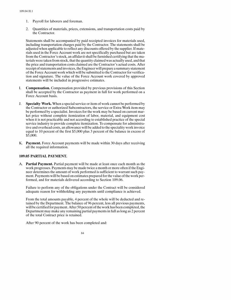
84
109.04 H.1
1. Payroll for laborers and foreman.
2. Quantities of materials, prices, extensions, and transportation costs paid bythe Contractor.
Statements shall be accompanied by paid receipted invoices for materials used,including transportation charges paid by the Contractor. The statements shall beadjustedwhen applicable to reflect any discounts offered by the supplier. Ifmate-rials used in the Force Account work are not specifically purchased but are takenfrom theContractor’s stock, an affidavit shall be furnished certifying that thema-terialswere taken fromstock, that thequantity claimedwas actuallyused, and thatthe price and transportation costs claimed are the Contractor’s actual costs. Afterreceiptof statementsand invoices, theEngineerwill preparea summarystatementof the ForceAccountworkwhichwill be submitted to theContractor for verifica-tion and signature. The value of the Force Account work covered by approvedstatements will be included in progressive estimates.
I. Compensation. Compensation provided by previous provisions of this Sectionshall be accepted by the Contractor as payment in full for work performed on aForce Account basis.
J. Specialty Work.When a special service or item ofwork cannot be performed bythe Contractor or authorized Subcontractors, the service or ExtraWork itemmaybe performed by a specialist. Invoices for the workmay be based on current mar-ket price without complete itemization of labor, material, and equipment costwhen it is not practicable and not according to established practice of the specialservice industry to provide complete itemization. To compensate for administra-tive and overhead costs, an allowancewill be added to the specialitywork invoiceequal to 10 percent of the first $5,000 plus 3 percent of the balance in excess of$5,000.
K. Payment. Force Account payments will be made within 30 days after receivingall the required information.
109.05 PARTIAL PAYMENT.
A. Partial Payment. Partial payment will be made at least once each month as thework progresses. Paymentsmay bemade twice amonth ormore often if theEngi-neer determines the amount of work performed is sufficient to warrant such pay-ment. Paymentswill be based on estimates prepared for the value of thework per-formed, and for materials delivered according to Section 109.06.
Failure to perform any of the obligations under the Contract will be consideredadequate reason for withholding any payments until compliance is achieved.
From the total amounts payable, 4 percent of the whole will be deducted and re-tained by the Department. The balance of 96 percent, less all previous payments,will be certified for payment.After 50percentof theworkhasbeencompleted, theDepartmentmaymake any remaining partial payments in full as long as 2 percentof the total Contract price is retained.
After 90 percent of the work has been completed and:

85
109.05 C
1. all pit releases, receipts of payment, and haul road releases are on filewith theDepartment; and
2. all payrolls have been submitted and are up to date; and
3. the remainingwork canbe completedwithout accrual of liquidateddamages;and
4. the Contractor is making a diligent effort to complete thework remaining onthe project;
TheEngineermay prepare a semifinal estimate for thework completed and retainnot less than 1 percent of the dollar amount of work completed. The remainder,less all previous payments, will then be certified for payment.
After all original Contract work is completed and conditions 1 through 4 abovehave been met, the Engineer may prepare a semifinal estimate for the work com-pleted and retain less than one percent of the dollar amount of work completed.The actual amount of retainage must be approved by the Construction Engineer.
Payments authorized under this section shall not constitute final acceptance ofanyportionof the project. TheContractor shall be responsible for final deliveryofthe project as specified in the Contract documents, regardless of any paymentsmade.
B. Prompt Payment.The PrimeContractormust pay the Subcontractor the amountdue for work done or services rendered, less applicable retainage not to exceed 2percent, from the current progress payment within 20 calendar days of receipt ofpayment form theDepartment or owning agency, unless the PrimeContractor hasjust cause to notmake payment. If the Prime Contractor withholds payment fromthe Subcontractor, the Prime Contractor must immediately notify the Subcon-tractor and the Project Engineer, inwriting, the reasons for withholding payment.The Subcontractor may also notify the Engineer if prompt payment has not beenmade.
If the Department or owning agency determines the Prime Contractor iswithholding payment without just cause, interest will accrue at the rate providedbyNDCC1301.1--02.ThePrimeContractor is responsible for paying the accruedinterest starting on the twenty-first calendar day after the Prime Contractorreceivespayment. If thePrimeContractor iswithholdingSubcontractorpaymentswithout just cause, the Department or owing agency may suspend all paymentsdue to the Prime Contractor, until the Subcontractor is properly paid and theContractor agrees to make payments as specified. If the Department or owningagency determines there is just cause for withholding payment, interest will notaccrue on the amount due.
These prompt payment procedures apply to all tiers of Subcontracts and are basedon 49 CFR 26.29
C. Retainage. The Department or owning agency will determine whether the Sub-contractor’sworkhasbeen “satisfactorily completed.”ASubcontractor’swork issatisfactorily completed when all of the tasks called for in the Subcontract havebeen accomplished, documented in accordancewith theContract, and paid for on

86
109.05 C
a pay estimate. To be satisfactorily complete, a Subcontractor must provide allnecessary final documentation required in theContract.Final documentationmayinclude, but is not limited to: certified payrolls, materials certification, haul roadreleases, pit receiptsofpayment, pit releases, nightwatchmanreports,warrantees,operating manuals, product literature, verification of final quantities, and theDBE Certification (SFN 14268).
If the Prime Contractor elects to use retainage on Subcontract work, prompt pay-ment shall also include the release of retainage monies that have been withheldfrom the Subcontractor within 20 days after the Subcontractor’s work issatisfactorily completed. Non-bonded Subcontractors must submit proof of pay-ment for all material bills and wages to the Prime Contractor before the PrimeContractor is required to pay the retainage. If retainage is not released as per thisprovision, interest will accrue at the rate provided by NDCC 13--01.1--02 begin-ning the twenty-firstcalendar day after the Subcontractor’s work is satisfactorilycompleted.
The release of retainage applies to all tiers of Subcontracts.
D. NoCircumvention.Onfederal-aidContracts theContractor shallnot includeanyprovision in its Subcontract that would circumvent 49 CFR Part 26.29.
109.06 PAYMENT FORMATERIAL ON HAND.
Paymentwill not bemade formaterials delivered to, or stockpiled on, the project untilincorporated in the work in their final position, except as specified in this Section.
Requests for paymentofmaterial onhandshall be submitted inwriting to theEngineer.Adelivery invoice itemizing thematerialmust be supplied for all stockpiledmaterials,except materials manufactured by the Contractor. A statement from the Contractorcertifying that thematerialmeets specifications, or in the case of stockpiled aggregate,that it willmeet specifications at the time of placement, is required for payment ofma-terial onhand.ForContractormanufacturedmaterials to be eligible for payment, a ful-lydocumentedstatementofproductioncosts; including the typeofmaterial, amountofmaterial stockpiled, location of stockpile and itemized breakdown of the cost for pro-ducing the material shall be submitted to the Engineer.
The Contractor shall furnish paid invoices for all stored materials that have not beenincorporated into the permanent work within 35 days of the date the Department sub-mitted the estimate for payment. An estimate submitted for payment date is shown onthe top of the detail pages. The paid invoice shall include a notarized statement fromthe supplier or fabricator certifying that payment hasbeen received. If a paid invoice isnot furnished, the quantity of any previously allowed material remaining in storagewill be deducted from the next progressive estimate, and further payment will not bemade until the material is incorporated into the work.
Payment for material on handwill be limited to the appropriate portion of the value ofthe Contract item and will not exceed the Contract Unit Price for the work item inwhich the material is used. Payment will not be made for materials in excess of Planquantities. Asmaterials are used in thework, credits equaling the partial payments forthem will be taken on future estimates.
To be eligible for payment, the value of the stored material to be used in one item ofwork must exceed $2,000.

87
109.08
Payment for material on hand will not include payment for fuels, supplies, form lum-ber, falsework, temporary structures, or othermaterialswhichwill not becomean inte-gral part of the finished work item.
No partial payment will be made on living or perishable plant materials until planted.
The material shall be delivered to or stockpiled near the project or other Engineer-approved storage facility.
Paymentmay bemade for structural steel to be used on bridge girders prior to fabrica-tion. Structural steel stockpiled at production plants or fabrication sitesmust be storedseparately toqualify for payment andshall beusedonly for the assignedContract.Pay-ment will not be made for reinforcing steel prior to fabrication.
If storedmaterial is lost, stolen, or damaged, thematerials valuewill be deducted fromthe subsequent estimate or estimates. Payments authorized shall not constitute finalacceptance of the material and the Contractor shall be responsible for such materials.Payment of partial estimates for stored material, acceptance of the materials to bestored, or approval of the storagemethoddoesnot relieve theContractor’s responsibil-ity for all materials andwork uponwhich payments have beenmade or the restorationof any damaged work. The payments are not a waiver by the Department of any otherContract provisions or of its rights to require fulfillment of all Contract terms.
Materials paid for by theDepartment are thepropertyof theDepartment, but the riskofloss shall remain with the Contractor. If materials for which the Department has paidare later found tobeunacceptable, then theDepartmentmaywithhold amounts reflect-ing such unacceptable materials from payments otherwise due the Contractor.
In the event of default, theDepartmentmay use or cause to be used all paid-formateri-als in any manner that is in the best interest of the Department.
109.07 COMPENSATION FOR ALTERED QUANTITIES.
When the accepted quantities of work vary from the quantities in the bid schedule, theContractor shall accept as payment in full, so far asContract items are concerned, pay-ment at the original Contract Unit Price for the accepted quantities of work done. Noallowance except as provided in Section 104.03 will be made for any increased ex-pense, loss of expected reimbursement, or loss of anticipated profits suffered orclaimed by the Contractor, whether resulting directly from alterations in the work orindirectly fromunbalanced allocationof overhead expenses among theContract itemsor from any other cause.
109.08 ACCEPTANCE AND FINAL PAYMENT.
When the Project has been accepted as provided in Section 105.13, the Engineer willprepare the final estimate for work performed. After approval of the final estimate bythe Contractor, the entire sum due will be paid after deducting all previous paymentsand all amounts owed to the Department or to be retained or deducted under the Con-tract provisions.
All prior partial estimates and payments shall be subject to correction in the final esti-mate and payment.

88
109.08
The Contractor may be required to furnish proof of compliance with all laws whichdirectly or indirectly apply to the work before any partial or final payment is made.
109.09 CONVERSION TOMETRIC SYSTEM.
The transportation industry is moving toward adoption of the Metric System, alsoknown as the International System of Units (SI). AASHTO has officially endorsedsuch action, and uses the Metric System to establish standard sieve sizes inAASHTO M 92.
Some applicable conversion factors are as follows:
To Convert From To Multiply ByInch Metre (m)* .0254 or 2.54 × 10--2Foot Metre (m) .3048 or 3.048 × 10--1Foot2 Metre2 (m2) .092903040 or 9.2903040 × 10--2Yard2 Metre2 (m2) .836127360 or 8.36127360 × 10--1Foot3 Metre3 (m3) .028316847 or 2.8316847 × 10--2Yard3 Metre3 (m3) .764554858 or 7.64554858 × 10--1Pound (Mass) Kilogram .453592370 or 4.53592370 × 10--1Gallon (U.S.) Metre3 (m3) .003785411784 or 3.785411784 × 10--3
Metre Inch 39.37007874Metre Foot 3.280839895Metre2 (m2) Foot2 10.76391042Metre2 (m2) Yard2 1.195990046Metre3 (m3) Foot3 35.31466621Metre3 (m3) Yard3 1.307950619Kilogram Pound (Mass) 2.204622622Metre3 (m3) Gallon (U.S.) 264.172052
Additional informationandconversion factors canbe found inAASHTOR1orASTME 380.
*The spelling “metre” is preferred by AASHTO, although “meter” is widely used.
SECTION 110ENVIRONMENTAL PROTECTION
110.01 DESCRIPTION.
This work consists of operational controls to be practiced and temporary pollutioncontrolmeasures to be taken to aid in controlling erosion andwater pollution resultingfrom construction operations.
Temporary erosion and pollution controlmeasures to be taken shall be those shownon thePlans, proposed by the Contractor and approved by or ordered by the Engineer during the
89
110.04
life of the Contract. Thework shall provide prevention, control, and abatement of waterpollution through the use of berms, dikes, dams, sediment basins, fiber mats, netting,gravel, mulches, grasses, slope drains, and other erosion control devices or methods.
Temporary erosion and pollution control measures shall be coordinated with perma-nent erosion control features specified elsewhere in theContract to the extent practicalto assure economical, effective, and continuous erosion control throughout the con-struction and post-construction period.
Temporary pollution control may include constructionwork outside the Right ofWaywhere roadway associated construction is necessary. This includes borrow pit opera-tions, haul roads, equipment storage sites, and plant sites.
110.02 MATERIALS.
Mulches may be hay, straw, wood cellulose, corn stalks, bark, corn cobs, wood chips,or other suitablematerial acceptable to theEngineer.Mulches shall be cleanand freeofnoxious weeds and deleterious materials.
Slope drainsmay be constructed of pipe, fibermats, rubble, portland cement concrete,bituminous concrete, plastic sheets, or other material acceptable to the Engineer thatadequately controls erosion.
Grass shall be quick-growing species suitable to the area and should provide a tempo-rary cover which will not later compete with grasses sown for permanent cover.
Sediment basins, sediment traps, barriers, and filters may be constructed by usingstaked hay or straw bales in conjunction with necessary earthwork.
110.03 PRECONSTRUCTION CONFERENCE.
The Contractor shall submit in writing, for acceptance at the preconstruction confer-ence or before starting work on the construction, a StormWater Pollution PreventionPlan (SWPPP). This plan shall include erosion and pollution controls on the projectsite, haul roads, borrow pit sites, plant sites, and the disposal of waste materials. Nowork shall be started until the plan for pollution control and prevention has been ac-cepted by the Engineer.
110.04 STORMWATER PERMITS
Any project with a contiguous area of disturbance greater than 1 acre requires a NorthDakota Pollution Discharge Elimination Systems (NDPDES) Construction permit.Projects that havemultiple individual sitesof activitywill require apermit if anyoneofthe individual sites has an area of disturbance greater than one acre.
The Contractor of each new project, meeting the criteria above, shall be required toopen an NDPDES permit by completing the permit application process.
The Contractor has day to day operational control of construction and activities and isthus an operator of the project under the permit. The operator is required by the permitto adhere to the conditions of the storm water permit and storm water pollutionprevention plan as it relates to controlling erosion and sedimentation during

90
110.04
Contractedactivities,maintainingerosioncontroldevices,conducting inspectionsandmaintaining appropriate records. The Contractor shall be required to complete andsign a permit application as it pertains to an operator.
When the Contractor’s project is finalized by the Department, the Contractor may bereleased from the storm water permit. If, at the time of finalization, the project meetsthe criteria for final stabilization the Department will file, or direct the Contractor tofile, a Notice of Termination (NOT) to the North Dakota Department of Health(NDDOH). If the project does not meet the criteria for final stabilization theDepartment shall be considered the sole permittee for the project. Department projectrecords shall serveasdocumentation for reporting the transfer of control for projects inlieu of the procedures outlined by the NDDOH for permit transfer.
110.05 OPERATIONAL CONTROLS.
A. Work Areas. Where a work area is adjacent to a live stream or lake, or runoffwater from the work area enters a live stream or lake, the Contractor shall erectbarriers or provide sediment basins to prevent direct runoff from reaching the livestream or lake.
Material shall not be transported across a live stream by fording. A temporarybridge or crossing shall be used for this purpose.
Mechanized equipment shall not be operated in a live stream channel except toconstruct required crossings or barriers and fills at channel changes.
Washwater from aggregate washing or other operations shall be held in a settlingbasin to prevent muddy water from entering the live stream or lake.
Portland Cement, fresh Portland Cement Concrete, oily or greasy material orwaste material shall not be dumped into or allowed to enter a live stream or lake.
Performwashout of concrete mixers, delivery trucks, and other delivery systemsin designated areas only.Contractorswill provide designated truckwashout areasthat will contain washout from concrete placement and construction equipmentcleaning operations. These areas must be self-contained and not drainable to anystorm water outlet of the site. Temporary concrete washout facilities shall beconstructed above grade or below grade at the option of the Contractor and shallhave a temporary pit or bermed areas of sufficient volume to completely containall liquid and waste concrete. Temporary concrete washout facilities shall beconstructed andmaintained in sufficient quantity and size to contain all liquid andconcrete waste generated by washout operations. Upon completion of construc-tion, washout areas will be properly stabilized. Payment for concrete washoutfacilities and associatedworkwill not bemade separately, but shall be included inthe price bid for other items.
The Contractor shall be responsible for the proper disposal of all removed con-crete, pavement, foundations, and other unsuitable material. The disposal siteshall not be a wetland and shall be a site acceptable to the Engineer.
Compliancewith these controls shall not relieve theContractor of the responsibil-ity to complywithother provisionsof theContract, nor the responsibility for dam-age and preservation of property.
91
110.07 A
110.06 EROSION CONTROLS.
The Engineer has the authority to limit the surface area of erodible earth material ex-posed by clearing and grubbing, excavation, borrow and fill operations; and to directthe immediate installation of permanent or temporary pollution control measures toprevent contamination of adjacent streams, watercourses, lakes, ponds, or other areasof water impoundment. Such work may involve construction of temporary berms,dikes, dams, sediment basins, slope drains, and use of temporarymulches,mats, seed-ing, or other control devices ormethods as necessary to control erosion. Embankmentand cut slopes shall be seeded and mulched as excavation proceeds to the extent con-sidered desirable and practicable.
The Contractor shall incorporate all permanent erosion control features into the Proj-ect at the earliest practical time as outlined in the accepted Plan. Temporary pollutioncontrol measures shall be used to correct conditions that develop during construction,that are needed before installing permanent pollution control features, or that areneeded temporarily to control erosionduring construction.These temporarymeasuresare not associated with permanent control features on the Project.
Clearing and grubbing operations shall be scheduled and performed so grading opera-tions and permanent erosion control features can follow immediately if Project condi-tions permit; otherwise temporary erosion controlmeasuresmay be required betweensuccessive construction stages.
The extent of clearing and grubbing operations and the excavation, borrow, and em-bankment operations for two-lane construction shall not cover a distance ofmore than3 miles. No work shall start in the fourth mile until necessary erosion and pollutioncontrol measures are completed in the first mile.
The extent of clearing and grubbing operations and the excavation, borrow, and em-bankment operations on four-lane construction shall cover a distance of notmore than2miles. Nowork shall start in the thirdmile until necessary erosion and pollution con-trol measures have been started in the first mile.
Ongradewidening and selective gradingProjects, theEngineerwill limit the extent ofclearing and grubbing, excavation, borrow, and embankment operations in progresscommensurate with the Contractor’s capability and progress in keeping the finishgrading, mulching, seeding, and other such permanent erosion and pollution controlmeasures current. Construction operations shall be limited to 5miles until erosion andpollution control measures have been started in the first mile.
Whena suspensionofwork isorderedorwhenoperationson theProject are suspendedfor the winter, the Contractor shall take all action necessary to control erosion, pollu-tion, and runoff during the shutdown period before the Department accepts responsi-bility for maintenance.
110.07 METHOD OF MEASUREMENT AND PAYMENT.
A. When temporary erosion and pollution control measures are required due toContractor’s negligence, carelessness, or failure to install permanent controls aspart of the scheduled work and are ordered by the Engineer, the work will not bemeasured for payment and shall be done by and at the Contractor’s expense.

92
110.07 B
B. Temporary erosion and pollution control work required, but not due to theContractor’s negligence, carelessness, or failure to install permanent controls,shall be performed as ordered by the Engineer. Work items required for this con-trol work that have a Contract price shall bemeasured as provided by the Specifi-cations for that item of work.
C. Should theContractor fail to control erosion, pollution, andsiltation, theEngineerwill employ outside assistance or State forces to do the work. The direct costs,overhead costs, and engineering costs incurred under these conditionswill be de-ducted from payments due the Contractor for work done on the Contract.

93
SECTION 150EQUIPMENT

94
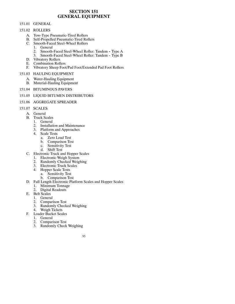
95
SECTION 151GENERAL EQUIPMENT
151.01 GENERAL
151.02 ROLLERSA. Tow-Type Pneumatic-Tired RollersB. Self-Propelled Pneumatic-Tired RollersC. Smooth-Faced Steel-Wheel Rollers
1. General2. Smooth-Faced Steel-Wheel Roller: Tandem -- Type A3. Smooth-Faced Steel-Wheel Roller: Tandem -- Type B
D. Vibratory RollersE. Combination RollersF. Vibratory Sheep Foot/Pad Foot/Extended Pad Foot Rollers
151.03 HAULING EQUIPMENTA. Water-Hauling EquipmentB. Material-Hauling Equipment
151.04 BITUMINOUS PAVERS
151.05 LIQUID BITUMEN DISTRIBUTORS
151.06 AGGREGATE SPREADER
151.07 SCALESA. GeneralB. Truck Scales
1. General2. Installation and Maintenance3. Platform and Approaches4. Scale Tests
a. Zero Load Testb. Comparison Testc. Sensitivity Testd. Shift Test
C. Electronic Truck and Hopper Scales1. Electronic Weigh System2. Randomly Checked Weighing3. Electronic Truck Scales4. Hopper Scale Tests
a. Sensitivity Testb. Comparison Test
D. Full Length Electronic Platform Scales and Hopper Scales1. Minimum Tonnage2. Digital Readouts
E. Belt Scales1. General2. Comparison Test3. Randomly Checked Weighing4. Weigh Tickets
F. Loader Bucket Scales1. General2. Comparison Test3. Randomly Check Weighing

96
4. Weigh TicketsG. Contractor Furnished Scale, Scale Person and Dump Person
1. General2. Construction Requirements3. Basis of Payment
151.08 MINING/BLENDING MACHINE
SECTION 152HOT BITUMINOUS EQUIPMENT
152.01 REQUIREMENTS FOR ALL MIXING PLANTS
A. GeneralB. Storage and Heating EquipmentC. FeedersD. DrierE. Thermometric EquipmentF. Flow Rate MeterG. Emission ControlH. Cold-Feed Control
152.02 SAMPLING DEVICES FOR MIXING PLANTS
152.03 SPECIAL REQUIREMENTS FOR BATCH MIX PLANTS AND FORCONTINUOUS MIX PLANTS
152.04 SPECIAL REQUIREMENTS FOR DRUM-DRYER MIXING PLANTS
A. GeneralB. Surge Bins
152.05 MILLING MACHINE
152.06 ASPHALT TRANSPORTER
SECTION 153PORTLAND CEMENT CONCRETE EQUIPMENT
153.01 BATCHING ANDWEIGHING EQUIPMENT
A. GeneralB. Automatic Batching Equipment
153.02 MIXERS
A. Stationary MixersB. Truck MixersC. Mobile Mixers
153.03 CONCRETE TRANSPORTING EQUIPMENT
A. GeneralB. Agitators
153.04 SIDE FORMS
153.05 SLIP FORM PAVING EQUIPMENT
97
153.06 ROADBED PLANERS
153.07 CONCRETE SPREADERS
153.08 VIBRATORS
153.09 CONCRETE FINISHING MACHINES
A. Transverse Finishing Machines for PCC PavementB. Bridge Deck Finishing MachinesC. Finishing Machines for Bridge Deck Overlays
153.10 HAND FINISHING EQUIPMENT
A. ScreedsB. Straightedges
153.11 SPRAYERS FOR LIQUID CURING COMPOUND
153.12 CONCRETE SAWS
153.13 JOINT AND CRACK CLEANING AND SEALING EQUIPMENT
A. GeneralB. Hot Poured Joint SealantC. Silicone Sealant
153.14 PREFORMED ELASTOMERIC COMPRESSION JOINT SEAL EQUIP-MENT
153.15 GRINDING MACHINE
153.16 HYDRODEMOLITION EQUIPMENT

98

99
151.02 B
SECTION 151GENERAL EQUIPMENT
151.01 GENERAL.
Equipment used on the work shall be of sufficient size and mechanical condition toproduce a product of specified quality. The Engineer may order the removal, replace-ment, or repair of any equipment that produces non-specification work.
The Contractor may request, in writing, permission to use alternative and innovativeequipment and shall furnish evidence that the proposed equipment produces workequal to the quality produced with specified equipment.
If permission is granted, permission may be withdrawn if the results are not satisfac-tory. Any defective or unsatisfactorywork produced shall be removed and replaced orcorrected at the Contractor’s expense.
Noadditional compensationwill beallowed for anydelaysor additional costs incurredas a result of applying this provision.
151.02 ROLLERS.
A. Tow-Type Pneumatic-Tired Rollers. The roller shall be equipped with at leastseven wheels with pneumatic tires of equal size and ply.
The wheels shall be arranged to provide complete coverage of the area the rollertravels.
The emptyandballastedweights shall bedetermined fromthemanufacturer’s rat-ing, provided the roller has not beenmodified from its original design and the bal-last furnished is of knownweight. If the roller has beenmodified or if the ballast isnotofknownweight, theContractor shall providea suitable scale forweighing theroller.
Tires shall be uniformly inflated so their air pressure will not vary bymore than 5psi. Rollers shall be operated with tire inflation pressures and wheel loads withinthe manufacturer’s recommended range for the size and ply of tire being used.Rollers shall be constructed so they can be loaded to a grossweight of at least 225pounds per inch of compaction width.
The tow-type rollers shall not be used to compact paver laid asphalt cement sur-faces except for incidental patching.
B. Self-Propelled Pneumatic-Tired Rollers. The roller shall be equipped with atleast seven wheels with pneumatic tires of equal size and ply.

100
151.02 B
The wheels shall be arranged to provide complete coverage of the area the rollertravels.
Rollers shall start, stop, and reverse direction smoothly, without jerking or back-lash, and shall be equipped with positive, accurate steering control.
To prevent pickup on asphalt pavement, the roller shall be equippedwith smooth-tread tires, close-fitting scrapers for eachwheel, and a system for uniformlymois-tening eachwheel without excessive use of water and detergent. Petroleumprod-ucts shall not be used formoistening thewheels. The roller shall be equippedwithskirting of sufficient size to retain heat on the tires. “Wobble-wheel” rollers shallnot be used.
Theemptyandballastedweights shall bedetermined fromthemanufacturer’s rat-ing, provided the roller has not beenmodified from its original design and the bal-last furnished for the roller is of knownweight. If the roller has beenmodified or ifthe ballast is not of knownweight, theContractor shall provide a suitable scale forweighing the roller.
The tires shall be uniformly inflated so their air pressure does not vary by morethan 5 psi. The roller shall be constructed so the contact pressure may be variedbetween 40 psi and 90 psi. The contact pressure shall be defined as the “averageground contact pressure,” expressed in psi, obtained when the wheel load inpounds is divided by the gross contact area in square inches of the tire. The Con-tractor shall furnish any data necessary to determine the contact pressures for thefull rangeof themanufacturer’s recommendedwheel loads and tire inflationpres-sures.
C. Smooth-Faced Steel-Wheel Roller.
1. General.All smooth-faced steel-wheel rollers shall be self propelled and ca-pable of starting, stopping, and reversing direction smoothly,without jerkingor backlash.The roller shall be equippedwithpositive, accurate steeringcon-trol. The face of all rollers shall be smooth and free from defects which willmar the surfaceof thematerial beingcompacted.Eachwheel or roller shall beequipped with adjustable spring scrapers, and a system for uniformly mois-tening the full width of each roll or wheel without use of excess water.
2. Smooth-Faced Steel-Wheel Roller: Tandem - Type A. This roller shallmeet Section 151.02 C.1 and the following requirements:
The empty and ballasted weights shall be determined from the manufactur-er’s rating, provided the roller has not beenmodified from its original designand theballast furnished isofknownweight. If the roller hasbeenmodifiedorif the ballast is not of known weight, the Contractor shall provide a suitablescale for weighing the roller.
The roller shall be of a two-axle or three-axle tandem design and when fullyballasted shall have a gross weight of 10 tons or more.
3. Smooth-Faced Steel-Wheel Roller: Tandem - Type B. This roller shallmeet Section 151.02 C.2 except thatwhen fully ballasted it shall have agrossweight of 8 tons or more with no specified contact pressure.

101
151.02 D
D. Vibratory Rollers. Vibratory rollers shall be of sufficient size and number tokeep up with roadway production and provide the specified density.
Vibratory rollers for use on rock embankments, granular borrow, and bases shallmeet speed and frequency ranges (vibrations per minute) shown in Table 151-1.Rollers should be operated at high amplitude unless otherwise directed and theroller speed and the vibrations per minute coordinated so there is aminimum of 6impacts per linear foot.
TABLE 151-1AGGREGATE BASE AND EARTHWORK
Impacts per Linear FootRollerSpeedM.P.H.(ft./min.) 1000 1200 1400 1600 1800 2000 2200 2400
(Vibrations per Minute)
1.0 (88)1.5 (132)2.0 (176)2.5 (220)3.0 (264)3.5 (308)4.0 (352)4.5 (396)
11.317.6------------
13.69.16.8----------
15.910.68.06.4--------
18.112.19.17.36.1------
20.413.610.28.26.85.8----
25.016.712.510.08.37.16.3--
22.715.211.49.17.66.5----
27.218.213.610.99.17.86.86.1
Vibratory rollers used on plant mix base and hot bituminous pavement shall beoperated at the speed (mph) and frequency ranges to provide a minimum of 10impactsper linear foot as shown inTable 151-2.Rollers shall be amplitudeadjust-able and operated at low amplitude unless otherwise directed. Only drum-typerollers will be permittedmeeting the followingminimum requirements: 1800 vi-brations per minute (VPM), static force on drums of 135 pounds per linear inch(PLI) of roller width, and total applied force on vibrating drums (dynamic plusstatic) of 300 pounds per linear inch (PLI).
Rollers shall be self propelled, and equippedwith spray bars to prevent pickup ofasphalt material. Vibrators shall shut off automatically whenever the roller stops.Rollers shall be capable of being operated as a static roller.
Vibratory rollers shall be equippedwith an accurate andworking gauge or gaugesfor measuring the frequency of each drum or the Contractor shall provide the En-gineerwith an accurate hand-held resonant reed tachometer for each roller beforeusing the roller on the Project. If the frequency gauge malfunctions or the ta-chometer is damaged, the Contractor shall have 48 hours to repair or replace it orthe roller cannot be used on the Project.

102
151.02 D
Full instructionson theproceduresofmakingamplitudeadjustments shall accom-pany each roller.
TABLE 151-2ASPHALT PAVING
Impacts per Linear FootRollerSpeedM.P.H.(ft./min.) 1800 2000 2200 2400 2600 2800 3000
(Vibrations per Minute)
1.0 (88)1.5 (132)2.0 (176)2.5 (220)3.0 (264)
20.413.610.2----
25.016.712.510.0--
22.715.211.4----
27.218.213.610.9--
29.519.714.811.8--
31.821.215.912.710.9
34.122.717.013.611.4
When the roller is in the static mode and prior to achieving required density, thetraveling speed shall not exceed 4 mph.
E. Combination Rollers.Combination Rollers shall meet the requirements of Sec-tion 151.02D, except they shall have a single vibrating drum in the front and foursmooth pneumatic tires in the rear. The roller shall have a gross weight of 20 tonsor more.
The tires shall be of equal size and ply and shall be uniformly inflated so the airpressure of each tire does not vary bymore than 5 psi. The contact pressure of thetires shall be as defined in Section 151.02 B.
F. Vibratory Sheep Foot/Pad Foot/Extended Pad Foot Rollers.Vibratory sheepfoot/pad foot/extended pad foot rollers shall be capable of developing centrifugalforce of 50,000 pounds or more, have a minimum operating weight of 23,000pounds, and a minimum roller width of 6 feet.
151.03 HAULING EQUIPMENT.
A. Water-Hauling Equipment.Water haulingunits shall be equippedwith a spray-ing device capable of evenly distributingwater over the designated area. Thewa-ter tank and all connections shall be watertight.
B. Material-Hauling Equipment. The hauling vehicles shall have a dump box ca-pable of controlled discharge onto the roadbedor into pavers. The dumpbox shallbe constructed and maintained so material is not lost during transit.
Bituminousmixture haul trucks shall be equippedwith a smooth-lined dumpbox,free from cracks, holes, or deep dents. The truck frame or dump body shall notmake direct contactwith the paver, and the truck or box shall not exert pressure onthe paver during dumping operations. The dump box shall be lubricated whennecessary with a thin film of material that does not dissolve the bitumen. Beforeuse, excess coating shall be drained out of the box. Petroleum distillates such askerosene or fuel oil will not be permitted.
103
151.05
A hole of sufficient diameter to receive the thermometer shall be provided on thedriver’s side of the truck box at the approximate intersection of imaginary diago-nal lines drawn from the corners of the truck box.
Each truck shall be equipped with a cover made of canvas or other suitable mate-rial of adequate size to protect the hot mix from the weather.
151.04 BITUMINOUS PAVERS.
Self-propelled pavers shall be provided with a full width vibrating screed, heated ifnecessary, and capable of spreading and finishing the mix in lane widths to the speci-fied typical section and thicknesses shown on the Plans.Hydraulic extendable screedsmay be used for variable width pavements. The paver shall have an auger that extendsto within one foot from either edge of the vibrating screed. Pavers used for shouldersand similar construction shall spread and finish themix in widths shown on the Plans.
The paver’s receiving hopper shall have sufficient capacity for a uniform spreadingoperation and with a distribution system that places the mixture uniformly in front ofthe screed.
The screed or strike-off assembly shall produce the specified finished surfacewithouttearing, shoving, or gouging the mixture.
The paver shall operate at speeds consistentwith continuous and uniform laying of themixture.
The control system shall automatically control the elevation and transverse slope ofthepaver screed.A30-footminimumlength rolling straightedge, erected stringline, orother approved device shall be used to establish the grade reference for control of thescreed height. The tension in the stringline shall be adequate to prevent deflection dueto theweight of the grade sensor. The systemshall permit the grade reference device tooperate on either side of the paver, and shall maintain the desired transverse slope re-gardless of changes in screed elevation. The system shall be capable of conversion tomanual control of the screed slope and elevation. Whenever breakdown or malfunc-tion of the automatic screed controls occurs, the equipmentmay be operatedmanuallyfor the remainder of that working day, provided the finished product meets Specifica-tions. Frequent or prolonged breakdown shall constitute cause for work suspensionuntil satisfactory repairs or replacements are made.
151.05 LIQUID BITUMEN DISTRIBUTORS.
Distributors shall be mounted on a truck capable of maintaining uniform speeds forproper application of the bitumen.
The distributor shall apply the bitumen uniformly on the designated area, at the speci-fied rate, within a tolerance of 0.02 gallon per square yard.
The truck shall be equipped with a tachometer, visible to the driver, which accuratelyregisters the truck speed in feet per minute. The tachometer shall be operated by awheel independent of the truck wheels.
Thedistributor shall beequippedwithacirculatingheating systemthat evenlycontrolsthe heating of the bitumen to the specified temperature. The tank shall be equippedwith a visible thermometer that accurately registers the temperature of the contents.

104
151.05
Thedistributor pressurepumpshall be capable ofmaintaining auniformand sufficientpressure throughout the full length of the spray bar during operation. A gauge shall beprovided which shows the pump output in gallons per minute.
The distributor shall be equipped with full-circulation spray bars designed to permitany adjustments necessary to obtain uniform, complete distribution of bitumen on thedesignated area. The flow of bitumen through the spray nozzles shall be controlled bycutoff valves to start and stop the flow quickly and uniformly over the length of spraybar without dripping. The Contractor shall provide data showing the manufacturer’sinstructions or recommendations for spray bar height above the road surface, nozzlesize, and angle of spray fan with the spray-bar axis.
A workable gauge shall be visibly located on the distributor tank for determining thequantity ofmaterial in the tank at any time. TheEngineermay require that the distribu-tor be calibrated at any time. All necessary means and assistance for calibrating thedistributor shall be provided by the Contractor.
For each distributor, the Contractor shall provide charts, tables, or other means for ac-curate, rapid determination of application rates in gallons per square yard for variousspray bar widths, truck speeds, and pump pressure, or output.
151.06 AGGREGATE SPREADER.
The aggregate spreader shall deposit the designated quantity of aggregate per squareyard in a smooth, uniform layer on the freshly deposited bitumen so the equipmentwheels do not contact any bitumen not covered by aggregate. The rate of aggregatedischarge shall be uniform over the full application width, and whenever necessary,cutoff plates shall be provided to reduce the width of spread in suitable increments tomeet job requirements.
The application width of the spreader shall be adequate to cover the full width of onetraffic lane plus one foot; however, the applicationwidthwill not be required to exceed13 feet.
151.07 SCALES
A. General. The Contractor shall have the scale tested and certified by theWeightsandMeasuresDivisionof thePublicServiceCommissionor a certified scale serv-ice within 6 months prior to use on the Project. Before beginning the weighingoperation, the Engineer shall test the scale, and if the scale is not within the re-quired tolerance, the Engineer may serve written notice to have the scale retestedby an approved agency before allowing it to be used on the Project.
TheContractor shall bear all expenses for having scales tested and certified by theWeights and Measures Division of the Public Service Commission or a certifiedscale service, and for making weight comparisons with other scales.
The scale shall not be altered from themanufacturer’s original design unless altera-tions are approved by the Weights and Measures Division of the Public ServiceCommission or a certified scale service, and specifically shall not be altered toweigh loads in excess of the rated capacity of the scale.
The Contractor shall provide 100 pounds of test weights in units of 50 poundseach. Weights shall be made of metal not easily altered in size or weight. Each

105
151.07 B.4.b.(1)
weight shall be certified as toweight by theWeights andMeasuresDivision of thePublic Service Commission or a certified scale service, and stamped or perma-nently marked with its certified weight.
Scale personsmaynot beprovidedby theDepartmentwhenelectronic scaleswithautomatic printers are used.
TheContractor is responsible formeeting the legal load limits established by law.
B. Truck Scales.
1. General. For each truck scale, the Contractor shall furnish a weather tightbuilding equipped with light, heat, air conditioning, and a chair or stool forthe scale operator’s use. The building shall enclose the recording beams ofthe scale.
2. Installation and Maintenance. The scale shall be installed on a firm, levelfoundation.Allworking parts shall be installed andmaintained in correct po-sition with respect to level and vertical alignment. Adequate clearance shallbemaintained around allworking parts. Knife-edge pivots shall be sharp andstraight, and pivot-bearing surfaces shall be smooth. The scale shall becleanedasnecessary for theproper functioningandaccuracy.TheContractoris responsible for keeping the scale platform clean.
3. Platform and Approaches. The scale shall have a platform of adequatelength to weigh the longest truck or truck-trailer combination in one opera-tion or,
a. The truck or truck-trailer combination shall be weighed on separatescales whose platforms are at the same elevation and arranged to permitsimultaneous weighing of the entire unit, or,
b. The wheel loads of the truck or truck-trailer combination may beweighed in separate operations provided any wheels not resting on thescale platform are supported on a concrete or asphalt paved level ap-proach or on an independent level platform rigidly constructed of woodor steel.
4. Scale Tests.TheContractor shallmaintain the scale balance and conduct thetesting as the Engineer deems necessary to insure that the scale accuracy iswithin the Specifications. If the scale does not meet the tolerances specifiedbelow, use of the scale shall be discontinued until the scale is repaired and iswithin the specified tolerances. The scale shall meet the following:
a. Zero Load Test.When no load is on the scale and all beamweights areset at zero, the scale shall be adjusted to balance or to read zero.
b. Comparison Test.The scale shall bemaintainedwithin plus orminus 1percent of the correct weight of the applied load. A minimum of onecomparison test is required for every 5,000 tons of material weighed orone day’s production, whichever is greater. The comparison test can bemade by one of the following methods:
(1) A loaded truck, which has been weighed on the Contractor’s scalewill be randomly selected by Department personnel at a randomtime and weighed on another certified scale.

106
151.07 B.4.b.(2)
(2) A piece of equipment that has been certified as to weight shall beweighed on the Project scale. The piece of equipment shall weigh atleast 60 percentof themaximumweightwhichwill be applied to thescale for the Project. The certified weight shall be initially deter-mined at the time the scale is certified and rechecked each time thescale is recertified. The piece of equipment shall have a plate show-ing the certifiedweightwelded to it. Thepieceof equipment shall becleanofmudanddirt and shall be refueledeach time it isused for theweight comparison. Recertification will be required when anychanges, such aswheel weights and ballast aremade that will affectthe certified weight.
When a piece of equipment with a certified weight is used to makescale checks,weight comparisons are to bemadewith another certi-fied scale for the first 2 daysof operation andonce amonth thereafter.
Any weight comparisons that do not meet Specifications (plus orminus 1 percent of the applied load) will be rechecked after adjust-ments are made.
c. Sensitivity Test.Aweekly sensitivity test shall be made by adding 100pounds of test weights to the scale after a loaded truck is on the scale andthe load has been weighed. If the scale is not sensitive to the addedweight, the scale shall not be used on the Project until it has been re-paired.
d. Shift Test. The scale shall weigh within the required accuracy regard-less of the position of the load on the scale platform. The performance ofthe scale with off-center loading shall be checked by comparing the re-sults obtained byweighing a loaded truckwith: (1) the rearwheels at theextreme end of the scale platform; (2) the position of the truck is then re-versed with the rear wheels at the extreme opposite end of the platform;and (3) the truck is centered on the scale platform.
This test shall be performed at the beginning of the Project and at leastone other timeduring theProject.Weight differences shall not be greaterthan 0.2 percent of one another.
C. Electronic Truck and Hopper Scales.
1. Electronic Weigh System. The electronic digital weigh station shall use aload cell or cells. All scales shall conform to the current edition of the Na-tionalBureauofStandardsHandbook44.Theweight indicated shall be accu-rate to within 1.0 percent of the true weight.
The system shall include an automatic printer that provides the followingminimum information:
a. Project Number (numerical) f. Gross Weightb. Date g. Tare Weightc. Time h. Net Tons in the Loadd. Ticket Number (consecutive) i. Product Designatione. Haul Unit Number
Items f and g will not be needed if the material is weighed in a hopper scale.

107
151.07 D.1
The printer shall produce a minimum of two copies of each ticket with amaximum size of 5-1/2 × 8-1/2 inches, and the words and numerals shall beclear and legible.
The printer and the control shall be programmed or otherwise equipped toprint aword or symbol identifyingwhen anyweight information ismanuallyentered.
If the printer or control malfunctions, manual weighing and recording asspecified in Section 151.07Bwill be permitted.Also, in the event of a printeror controlmalfunction,material that is in storage or in a surge binmay be de-livered to the roadway, if the weight of the material can be accurately estab-lished.
2. Randomly Checked Weighing. When a Department scaleperson is notused, the Engineer shall validate the truck and/or material weight by ran-domly reweighing the truck. The Engineer shall randomly select aminimumof one loaded truck for each 5,000 tons ofmaterial weighed or one day’s pro-duction, whichever is greater, to validate the weight. The weight checkmustbe done on a certified scale.
Should the randomweight checks discloseweight differences ofmore than 1percent using the comparison test, the scale shall be retested and adjusted asnecessary to assure accurate weighing.
3. Electronic Truck Scales.Electronic truck scales shallmeet Sections151.07A and 151.07 B.
4. Hopper Scale Tests.
a. Sensitivity Test.Aweekly sensitivity test shall be made by adding 100pounds of test weights after the hopper scale is loaded and weighed. Ifthe scale is not sensitive to the added weight, the scale shall not be usedon the Project until it has been repaired.
b. Comparison Test.The scale shall bemaintainedwithin plus orminus 1percent of the correct weight of the applied load. One comparison test isrequired for every 5,000 ton of material weighed or one day’s produc-tion, whichever is greater. The test shall be made by comparing theweight of thematerial in the hopper and theweight of thematerial after itis weighed on another certified scale.
D. Full Length Electronic Platform Scales and Hopper Scales. The Full LengthElectronicPlatformScale (FLEPS) shall be equippedwith aplatformof sufficientlength that the longest hauling unit can be weighed in one operation. Split weigh-ing will not be allowed.
1. Minimum Tonnage. The Contractor shall furnish a Full Length ElectronicPlatformScale or anElectronicHopperScale onanyContract that containsatleast one pay item whose quantity must be determined by weighing, and theestimated quantity of that pay item is 50,000 tons or more. The Contractormay use other approved scales to weigh pay items of lesser tonnage.
108
151.07 D.2
2. Digital Readouts.Each FLEPS andHopper Scale shall be equippedwith anelectronic digital readoutwhich displays the tonnage beingweighed andwilloperate continually during weighing operations.
E. Belt Scales.
1. General. Belt conveyor scales shall comply with the requirements for Belt-Conveyor Scales in the current edition of the National Bureau of StandardsHandbook No. 44. The weight indicated shall be accurate to within 1.0 per-cent of the true weight.
2. Comparison Test.At the beginning of each day, the Contractor shall weighfiveormore loads fromsequential haulingunits and compare the totalweightwith the total weight of the same loads taken on a platform scale meetingspecification requirements. The belt scale shall be maintainedwithin plus orminus 1 percent of the platform scale.
3. Randomly CheckedWeighing. The Engineer will randomly select a mini-mum of one loaded truck for every 1,000 tons of material weighed or oneday’s production,whichever is less, to validate theweight. Theweight checkmust be done on a certified scale.
Should random weight checks disclose weight differences of more than 1.0percent, the scale shall be retested using the comparison test and adjusted asnecessary to assure accurate weighing within 1 percent.
If testing shows the scale has been under-weighing, it shall be adjusted im-mediately. TheContractor shall not be compensated for any loss fromunder-weighing.
If the scale hasbeenover-weighing, its operation shall cease immediatelyun-til adjusted. The Engineer will determine the weight of all material weighedafter the last comparison testmeeting the specified requirements.Thisweightwill be reduced by the percentage of scale error that exceeds one percent todetermine the pay quantity.
4. WeighTickets.TheContractor shall provide twocopiesofweigh tickets thatprovide the following minimum information:
a. Project Number e. Hauling Unit Number
b. Date f. Net tons in the load
c. Time g. Pit Location
d. Ticket Number (Consecutive) h. Type of Material
The tickets and weighing procedures shall be approved by the Engineer.
F. Loader Bucket Scales.
1. General. Loader bucket scales shall use a load cell or cells. All scales shallconformto thecurrent editionof theNationalBureauofStandardsHandbook44. The weight indicated shall be accurate to within 1.0 percent of the trueweight.

109
151.07 G.2
2. Comparison Test. At the beginning of the first day of production, theContractor shall weigh three ormore loads from sequential hauling units andcompare the total weight with the total weight of the same loads taken on aplatform scalemeeting specification requirements. Load the trucks using theloader scale in dynamic mode. The loading area shall be level. Operation ofthe loader scale shall be as recommended by the manufacturer for accurateweighing. The weight obtained from the loader bucket scale shall be withinplus or minus 1.0 percent of the platform scale.
3. Randomly CheckedWeighing. The Engineer will randomly select a mini-mum of one loaded truck for each day’s production to validate the weight.The weight check must be done on a certified scale.
Should random weight checks disclose weight differences of more than 1.0percent, the scale shall be retested using the comparison test and adjusted asnecessary to assure accurate weighing within 1.0 percent.
If testing shows the scale has been under-weighing, it shall be adjustedimmediately. The Contractor shall not be compensated for any loss fromunder-weighing.
If the scale has been over-weighing, its operation shall cease immediatelyuntil adjusted. The Engineer will determine the weight of all materialweighed after the last comparison test meeting the specified requirements.Thisweight will be reduced by the percentage of scale error that exceeds onepercent to determine the pay quantity.
Any timeduringproduction theEngineermay require the loader bucket scaleto be checked for accuracy.
4. Weigh Tickets. The computerized scale system shall include an automaticprinter that prints twoweigh tickets to beprovided to theEngineer containingthe following minimum information:
a. Project Number e. Hauling Unit Number
b. Date f. Net tons in the load
c. Time g. Pit Location (by legal description)
d. Ticket Number (Consecutive) h. Type of Material
The tickets and weighing procedures shall be approved by the Engineer.
G. Contractor Furnished Scale, Scale Person and Dump Person.
1. General. If specified on the Plans, this work shall consist of providing ascale, scale person, and dump person for proper construction of the Project.
2. Construction Requirements. The Contractor shall furnish and use a fulllength electronic truck scale meeting the requirements of Section 151.07 ofthe Standard Specifications and the following requirements for weighing allAggregate Base or specified materials on the Project.
The electronic truck scale system shall include an automatic printer for haultickets and haul sheets.

110
151.07 G.2
Thecomputerized scale systemshall includeanautomaticprinter that printsahaul ticket containing the following information:
a. Project Number g. Ticket Number
b. Time h. Gross Weight
c Haul Unit Number i. Net Weight (in tons)
d Tare Weight j. Material Spread Distance
e Type of Material k. Pit Location
f. Date
The system shall also print a daily haul sheet containing the following infor-mation:
a. Date g. Material Hauled
b. Project h. Running Total
c. Contractor i. Haul Sheet Number
d. Haul Sheet Total j. Pit Location
e. Type of Project k. Subcontractor
f. County l. Pit Owner
The haul sheet shall list each truck number and the net tons for each loadhauled and total tonshauled for eachunit. Ahaul sheet shall bemade for eachtype of material.
The haul sheet shall also include a certified statement stating that this is a trueand accurate quantity of material supplied to the Project and a line for theContractor’s signature. The haul sheet shall be signed by the Contractor andsubmitted to the Engineer at the end of each day. The haul sheet shall containa blank line for the Engineer’s signature.
In thecaseof computermalfunction,manualweighingwill notbeallowedformore than two consecutive work days.
The automated scale system shall be programmed so that when an over-weight load is on the scale, a ticket will not be printed. An overweight load isdefinedasany load that is 1,000poundsover theLegalGrossVehicleWeight.An overloadmessage with the gross vehicle weight shall be displayed so theoverload amount is known.
The Contractor shall also provide a scale person and a person to control thecontractor’s dumping operation. The scale person shall operate the comput-erized scale system and provide each truck driver with a scale ticket for eachload.The scale person shall check and record the tareweights of eachhaulingunit on a daily basis and provide a daily tare weight report to the Engineer.The scale person shall, under the observation of the Engineer, conduct scaletests as indicated in Section 151.07 B.4 a, c, and d of the Standard Specifica-tions to insure the scale is operatingwithin specification tolerances. The En-gineer will conduct test item b. Comparison Test by randomly selecting aloaded truck, already weighed, for the scale check. All scale checks shall bedocumented and given to the Engineer with the daily tare weight report.
111
152.01 B
If aweight comparison check shows the scale under-weighing, it shall be ad-justed immediately. The Contractor shall not be compensated for any lossfrom under-weighing.
If the scale has been over-weighing, (greater than the 1.0 percent limitation),operationswill cease immediatelyuntil adjusted. TheEngineerwill calculatethe combinedweight of all material weighed after the last test showing accu-rate results. This combinedweightwill be reduced by the percentage of scaleerror. The Contractor’s payment for this material will then be calculated us-ing the bid price times the reduced combined weight.
The dumpperson shall control theContractor’s truck-dumping operations toinsure proper material placement.
3. Basis of Payment. All costs to provide a full length electronic scale, scaleperson, dumpperson, haul tickets, and haul sheets shall be included in the bidprice for the item being hauled.
151.08 MINING/BLENDINGMACHINE.
Themining/blendingmachine shall be a self-propelledmachine designed to pulverizethe existing asphalt layers to a specifiedmaximum size. It shall be capable of uniformlyblending the pulverized material with existing or added aggregate base material. Themachine shall have a control system to automatically control the elevation of the cut-ting head and be heavy enough to mine and blend the material to the specified depth.
SECTION 152HOT BITUMINOUS EQUIPMENT
152.01 REQUIREMENTS FOR ALL MIXING PLANTS.
A. General. Intermingling of aggregate sizes shall be prevented by providing ade-quate space between stockpiles. Various plant units shall be designed and coordi-nated to permit uniform, uninterrupted production under normal operating condi-tions and shall be capable of accurately calibrating and checking the proportionsof each ingredient used in the mixture.
B. Storage and Heating Equipment. Storage tanks shall uniformly heat the bitu-men to the required temperature range, without damaging or changing its charac-teristics. Direct flame against the storage tanks will not be permitted. The tankshall be equippedwith a thermometer that accurately registers the temperature ofthe bitumen. The Contractor shall provide measuring sticks and outage tables foraccurately calibrating the tanks and checking the quantity of material in the tanksat any time. Bitumen storage or supply facilities shall adequately supplymaterialso the plant can operate at full capacity without interruption.

112
152.01 C
C. Feeders. The plant shall have an accurate mechanical means for feeding aggre-gates into the drier so uniform production and temperature is obtained.
D. Drier. The plant shall include one or more driers which continuously agitates,heats, and dries the aggregates as specified.
E. Thermometric Equipment. Temperature recording equipment shall be fur-nished that automatically and continuously records the mix temperature as it isdischarged from the plant. The equipment shall record temperature variations of20°F. within oneminute of the time the variation occurs. Themechanism shall beaccessible; have a transparent, dust-proof cover; and be located where it is unaf-fected by plant vibration. The mix temperature of each day’s production shall beautomatically recorded on a chart or charts suitably graduated to permit determi-nation of timewithin 15minutes and temperaturewithin 10°F. The charts shall besubmitted to the Engineer daily.
F. Flow Rate Meter. The quantity of asphalt cement being discharged into themixer shall be measured by a flow rate meter with totalizer, permanent recorder,and temperature compensation capabilities. The totalizer shall have the capacityof recording 1,000,000 gallons with a certified accuracy of ±0.20 percent. Theflow rate meter and totalizer shall be temperature-corrected automatically to60°F. within an operational range of 60° to 450°F.
The flow ratemeter shall continuously display and permanently record on a chartor printout the asphalt percentageof the totalmixona time-coordinatedbasis.Themaximumchart increments shall be0.10percent of the totalmix. If the flowvariesbymore than±0.25 percentage points from the set percentage of asphalt, theCon-tractor shall correct the oil variance. The Contractor shall have 1/2 hour after thefirst start up of the day and five minutes after any additional start up to adjust theplant to meet the tolerance. The recorder shall be accessible to the Engineer at alltimes, and the record of each day’s operation shall be submitted daily to the Engi-neer.
TheContractor shall calibrate the flowmeter for accuracy before the start of eachProject and as necessary during the course of the Project to assure the specifiedaccuracy.TheContractor shallmakeavailable to theEngineer a copyof theopera-tions manual of the flow meter.
G. Emission Control. Scrubbers or similar devices shall be used to meet pollutionstandards. Liquids from awet scrubber shall not be discharged into a live stream,lake, or pond. The effluent shall be circulated through sludge pits or tanks. Theresultant sedimentation, together with all other waste material developed bycrushing and mixing operations, shall be contained or otherwise acceptably dis-posed of.
H. Cold-Feed Control.When aggregate is handled by cold-feed control, all plantscreens are removed with the exception of a scalping screen used to preventoversize rock from entering themix. The scalping screen’s opening size shall notexceed the mix’s maximum size aggregate plus 1/2 inch. A mechanical feederhaving a separate bin for each aggregate to be blended in the mixture shall beprovided. Each bin shall be equippedwith dividers to prevent overflow of aggre-gate toadjacentbins, andshall havea separate andpositive feedcontrol that canbeeasily and accurately calibrated. The feed shall be quick-adjusting, and shall

113
152.05
maintain a constant and uniform flow of aggregate throughout the range of itscalibration.
152.02 SAMPLING DEVICES FOR MIXING PLANTS.
The plant shall be equipped for readily obtaining a representative sample of each sizeof aggregate, or of thecombinedaggregatebefore theaggregate enters themixingunit.
The Engineer shall have the right to obtain an aggregate sample at any time during themixing operation. The Contractor may stop the belt entering themixing plant to allowthe inspector to remove a sample or provide a sampling device that is easily operatedby the inspector without interrupting the mixing plant operation.
The sampling device shall be approved by the Engineer before the mixing plant is ap-proved for use on the Project.
152.03 SPECIAL REQUIREMENTS FOR BATCHMIX PLANTS AND FORCONTINUOUS MIX PLANTS.
The batch-type hot mix plant and the continuous type hot mix plant shall meet Sec-tion 152.01 of these Specifications except Section 152.01 F., and shall meet Sec-tion 152.02 of these Specifications and the requirements of AASHTO M 156.
152.04 SPECIAL REQUIREMENTS FOR DRUM-DRYER MIXINGPLANTS.
A. General. The drum-dryer hot mix plant shall meet Sections 152.01 and 152.02.
The drum-dryer mixing process shall provide positive weight control of the coldaggregate feed with a belt scale or other device to automatically regulate the feedgate and permit instant correction of variations in load. The cold-feed flow shallbe automatically coupled with the bitumen flow to maintain the required propor-tions. The system shall be equippedwith automatic burner controls and shall pro-vide for temperature sensing of the bituminous mixture at discharge.
The Contractor shall have, for review by the Department, a copy of themanufac-turer’smanual for the plant. Thepitch of the drumshall be nogreater than 3/4 inchper foot or as recommended by the manufacturer.
When plant production is changed during normal operations, the temperature ofthe mix shall be maintained within 20°F. of the average temperature of the mixproduced within the preceding 1/2 hour of the plant production change.
B. Surge Bins. The plant shall have adequate bin storage for the hot mix to ensurecontinuous production operations. Surge bins for hot storage shall have batchers,baffle plates, or other approved devices to minimize segregation during loadingandunloading.Surgebinswhichpermit anuninterrupted free fall ofmaterial fromthe loading conveyor shall not be used.
152.05 MILLINGMACHINE.
The milling machine shall be a self-propelled machine specifically designed to milland remove existing asphalt pavement to a specified depth, profile, cross slope, and

114
152.05
surface texture. Themachine shall be of a size, shape, and dimensions which does notinterfere with safe traffic passage adjacent to the work.
The machine shall have a control system to automatically control the elevation andtransverse slope of themilling head. A 15-foot minimum length skid, rolling straight-edge or other approveddevice shall be used to establish the grade reference for controlof the milling head. The system shall permit the grade reference device to operate oneither side of the milling machine, and shall maintain the desired transverse slope re-gardless of changes in the elevation of the milling head.
Conveyors capable of side, rear, or front loading shall be provided with the necessaryequipment to transfer the milled material from the roadway to a truck.
152.06 ASPHALT TRANSPORTER.
Tank trucks used to transport bituminous material shall be sealed at the refinery andshall be equippedwith a bitumen sampling valve. This valve shall be conveniently lo-cated for sampling, preferably in the lower half of the rear bulkhead and at least onefoot from the shell. The valve shall be inside the tank with the valve stem and outletextending outside the tank.
SECTION 153PORTLAND CEMENT CONCRETE EQUIPMENT
153.01 BATCHING ANDWEIGHING EQUIPMENT.
A. General.The batching plant, including its supports and foundations, shall be de-signed to safely withstand any operating stresses. The plant shall be leveled tomaintain accuracy of the weighing mechanism. Bins with suspended weighingequipment shall be fully loaded for a minimum of two hours before testing theweighing equipment. The weighing mechanism shall be constructed or shieldedto provide protection and accurate operation during windy or other adverseweather conditions.
The batching plant shall include individual bins or a binwith individual compart-ments, for each separate aggregate component, constructed to prevent intermix-ing of aggregate before weighing. The weigh hopper or hoppers shall be chargedto assure the batched weights are within the tolerances specified in Section802.04 B.1. The separate aggregate components for each batch may be weighedcumulatively in a single hopper or separately in individual hoppers. Whenweighed cumulatively, the aggregate shall be weighed in the specified sequence.A scalping screen or other devicewhich is capable of removing deleterious, over-sizedmaterial fromtheaggregateprior tocharging thebins shall beplacedoneachbin at the batching plant.
Bulk cement and fly ash shall be weighed in a hopper and kept separate from theaggregates. Thehoppers shall be attached to a separate scale forweighing compo-

115
153.01 B
nent materials. Bulk material shall be charged into the weigh hopper from aweatherproof bin equipped to permit accurate control of the quantity of materialwithdrawn for each batch, within the tolerance specified in Section 802.04 B.1.
The hoppers for weighing any ingredients shall be freely suspended on scaleswithout other contacts thatmay affect proper functioning of the scales. Theweighhoppers shall complete discharge without loss of materials and without manualassistance. If complete discharge cannot be obtained, the hoppers shall beequippedwith a vibrator. Hoppers shall hold thematerials beingweighedwithoutspillage and the discharge gates shall not leak when closed.
Hopperswhichare loadedbycompressedair shall bevented to relieveair pressurebuild up. This build up could cause faulty operation of the weigh mechanism orresult in false scale readings.
Weigh hopper scales shall be either the beam or springless dial type, of standardmakeanddesignequipped topermit quick, easybalancingat zero load.The scalesshall be accuratewithin a tolerance of 0.5 percent throughout the rangeof use. Fordial scales the predeterminedbatchweight of each ingredient beingweighed shallbemarkedon the dial face by an adjustable pointer.Beamscales shall be equippedwith an “over and under” indicator to show the beam in balance at zero load andprovide positive visual evidence of overweights and underweights. The beamscale shall include a separate beam for each ingredient being weighed.
The Contractor shall have the scale tested and certified by the Department ofWeights and Measures or a certified scale service within 6 months before use onthe Project.
The scales shall be tested as often as the Engineer deems necessary for continuedaccuracy. TheContractor shall provide at least one standard 50-pound testweightfor each500poundsof capacityof themaximumsize scale; however, not less than10normore than20such testweights shall be required.Anyscalewhichcannotbemaintained accuratelywithin the specified tolerance shall be replacedor repaired.TheContractor shallmake all arrangements andbear all expenses incurred inhav-ing the scales tested and certified.
B. Automatic Batching Equipment. Automatic batching shall be required forP.C.C. Pavement projects with 3,000 or more cubic yards of concrete. The auto-matic batching equipment shall conform to the general requirements of Section153.01 A and to the additional requirements of this Section.
For each batch a single actuation of a starting device shall be the onlymanual op-eration permitted to proportion the designated quantity of each ingredient into theweigh hopper or hoppers.
The automatic batching equipment shall be interlocked so that: (1) The chargingmechanism of any weigh hopper cannot be opened until the scale has returned tozero and the discharge mechanism of the weigh hopper has closed; (2) the dis-charge mechanism of the weigh hopper cannot be opened if the charging mecha-nism is open; (3) the dischargemechanism cannot be opened until all ingredientshave been batched to their designated weights, within the specified tolerances;and (4) if separate aggregate components are weighed cumulatively in a singlehopper, the aggregates are weighed in the specified sequence.
116
153.01 B
The designated batch weight of bulk cement and fly ash and of each separate ag-gregate component shall be preset at the directionof theEngineer before the batchcycle starts.
The automatic scales forweighing bulk cement and fly ash shall be equippedwithan automatic recording device to graphically record or print the batched andemptyweights. Graphic recording charts shall be graduated for time intervals notexceeding 15 minutes, and shall have minimum weight graduations not greaterthan0.1 percent of thenominal capacityof the scale. If printed tapes are used, theyshall record the consecutive batch number; and the minimum weight graduationprinted on the tape shall not exceed 0.1 percent of the nominal capacity of thescale.Theweight recordingmechanismshallbeaccuratewithinonegraduationofthe chart or tape.
The automatic batching equipment shall be capable of conversion to manual op-eration.Manual operationwill be limited to 12 hours for reasons of breakdown inthe automatic equipment, except by written permission of the Engineer.
153.02 MIXERS.
A. Stationary Mixers.Eachmixer shall be amechanicallyoperated revolvingdrumor revolving blade type. The mixer shall have attached, in a prominent place, amanufacturer’s certified rating plate showing the maximum mixer capacity, therecommended speed of rotation of the drumor blade (rpm), and themixer’s regis-trationnumber.Themixer shall have a rated capacityof not less than10cubic feet.A mixer of smaller capacity may be approved for items of work other than Con-crete Pavement (Section 550) andConcreteStructures (Section602) provided thevolume of concrete required for the pour is less than 10 cubic yards.
The total production capacity of the mixer or mixers shall be adequate to furnishconcrete at a rate which permits uninterrupted placement and finishing opera-tions.
Themixer shall be cleaned at intervals required to keep deposits of hardened con-crete from accumulating in the mixer drum. The pick up and throw over bladesshall be repaired or replaced when blade wear exceeds 10 percent of the originalblade depth. The Contractor shall: (1) have available at the job site a copy of themanufacturer’s design showing the original layout and dimensions of the blades,or (2) place permanent marks on each blade to show points of 10 percent wearfrom new conditions.
Multiple compartmentmixers shall be designed for synchronizedoperationof thecharging, mixing, transfer, and discharge cycles so that a single batchwill not be-come intermingled in the mixer with material from another batch.
Eachmixerwith a capacity of 10 cubic feet ormore shall be equippedwith awatermeasuring system.When themixer has a rated capacity less than10cubic feet, themixing water may be measured and added by approved manual methods. Thewater measuring systemmay bemounted on amixer or may be a separate unit lo-cated at themixing site. The system shall deliver the designated quantity of waterfor each batch within the tolerance specified in Section 802.04 B.1.e. The systemshall be constructed so the water flow to the mixing drum automatically stops
117
153.02 B
when the designated quantity of water has been delivered. The system shall bereadily adjustable and shall have an accurately calibrated indicator showing thequantity of water measured for each batch. Outside taps and valves or other ap-proved means shall be provided to permit convenient and accurate calibration ofthewatermeasuring system.TheContractor shall furnish all equipment andassis-tance necessary to calibrate the systembeforeuse andasnecessary tomaintain thespecified tolerances.
A visual volumetricmeasuring unitmust be used in all admixture dispensing sys-tems where the admixture dosage rate does not exceed 32 fluid ounces/100pounds of cement. The measuring unit shall be located where the plant operatorcanclearly read the indexpoints on themeasuringunit from theoperator’s station.A measuring unit will not be permitted in a plant where the batching office andbatch plant are widely separated or where the batch cycle time is insufficient toallow the fill and discharge of a measuring unit. In such cases, a flow indicatormust be installed in the admixture line to indicate to theplant operator the start andcompletion of each batch. Also, a suitable measuring unit must be installed in theline to allowchecking thedispenser accuracyperiodically.Aseparate dispenser isrequired for each admixture.
The revolvingdrum type stationarymixer shall have amanufacturer’s guaranteedcapacity capable ofmixing and holding a volume of concrete equal to its rated ca-pacity plus 10percentwithout spillage. The revolvingblade type stationarymixershall mix and hold a volume of concrete equal to its rated capacity without spill-age. The speedof rotationof themixingdrumorblades shall be as specifiedby themanufacturer.
When the stationarymixer has rated capacity of less than10 cubic feet, themixingcycle may be timed by anymethod approved by the Engineer.When the rated ca-pacity of themixer is 10 cubic feet ormore, themixer shall be equippedwith con-trols for automatically timing themixing cycle for each batch. The automatic tim-ing controls shall be interlocked with the discharge mechanism so no part of thebatch can be released until the designated mixing time has elapsed. The comple-tion of each mixing cycle shall be indicated by an audible or visual signal. Thetiming mechanism shall be constructed or enclosed so it can be locked when di-rected by the Engineer. If the timing device or interlocks break down or fail to op-erate properly, operation of the mixer may be temporarily controlled by an ap-proved manual timer until repairs can be made, provided a mixing time for eachbatch of not less than 90 seconds can be maintained. If repairs are not completedwithin 72 hours, further use of the mixer shall be discontinued. Each stationarymixer used tomix concrete for pavement shall be equippedwith an approvedme-chanical batch counter.
B. Truck Mixers. The maximum cubic yard capacities for mixing and agitatingshall be as guaranteed by themanufacturer on the rating plate attached to the truckmixer. The mixing speed for the revolving drum type mixer shall be not less thanfour revolutions per minute of the drum, nor greater than a speed resulting in aperipheral velocity of 225 feet perminute at the largest diameter of the drum. Themixing speed for the revolving blade type mixer shall be not less than four normore than 16 revolutions per minute of the mixing blade. The agitating speed foreither the revolving drum or revolving blade typemixer shall be not less than twonormore thansix revolutionsperminute.The truckmixer shall beequippedwitha

118
153.02 B
revolution counter which registers the number of revolutions of the mixing drumor blades when operated at mixing speed.
Themixer shall be cleanedat intervals, required tokeepdeposits of hardenedcon-crete from accumulating in the mixer drum. The pick up and throw over bladesshall be repaired or replaced when blade wear exceeds 10 percent of the originalblade depth. The Contractor shall: (1) have available at the job site a copy of themanufacturer’s design showing the original layout and dimensions of the blades,or (2) place permanent marks on each blade to show points of 10 percent wearfrom new conditions.
When the truckmixer carries flushwater for cleaning themixer, it shall be carriedin a compartment separate from themixingwater, and each compartment shall beequipped with a calibrated sight gauge.
C. Mobile Mixers. The mixer shall be self-propelled and carry sufficient unmixedmaterials for the concrete.
Themaximumcubic yard capacity shall be as certified by themanufacturer on therating plate attached to the truck mixer.
Themixer shall be capable of positive measurement of cement and flow of waterbeing introduced into themix.Avisible cement recordingmeter shall beprovidedand equippedwith a ticket printout showing the quantityused.Water flowshall beindicated by flowmeter and be readily adjustable to provide for minor variationsin aggregate moisture.
Themixerwill be calibrated by theDepartment to ensure that it is capable of auto-maticallyproportioningandblendingall componentson a continuousor intermit-tent basis, as required by the finishing operation. The Contractor shall furnish aplatformscale of 500-pound capacity, 300pounds of testweights, a container thatcan be placed on the scale, and a deflector to divert the material from the mixerinto the container. Each individual component (aggregate, sand, water, cement,and admixture), shall be calibrated individually and as a component.
The total production capacity of the mixer or mixers shall be adequate to furnishconcrete at a rate which permits uninterrupted placement and finishing opera-tions.
The mixer shall be cleaned at suitable intervals, and accumulations of hardenedconcrete shall be removed.
153.03 CONCRETE TRANSPORTING EQUIPMENT.
A. General. Any equipment used to transport freshly mixed concrete shall deliverthe concrete in a thoroughly mixed and uniform mass, meeting all requirementsfor slump, air content, and uniformitywhen discharged at the site. The equipmentshall have gates or other approvedmeans for controlling the discharge rate aswellas vibrators to aid in the discharge.
Equipment used for concrete placement, such as truck boxes, chutes, pipes, buck-ets, shovels, or wheelbarrows shall not contain aluminum.

119
153.05 A
B. Agitators. Agitating equipment shall be of the revolving-drum or open-top re-volving-blade types, ormay be a truckmixer operated at agitating speed. The agi-tating speedof the revolvingdrumorblades shall benot less than twoormore than6 revolutions per minute. The body or drum shall be a smooth, watertight, metalcontainer. The maximum cubic yard hauling capacity shall be shown on a ratingplate attached to each unit.
153.04 SIDE FORMS.
Straight side forms shall be made of a metal of not less than 7/32 inches thick and notless than10 feet long.Flexibleor curved formsofproper radius shall beused for curvesof 100-foot radius or less. Form design shall be acceptable to the Engineer; and theforms shall have adequate devices for secure setting so that when in place they with-stand, without spring or settlement, theweight impact and vibration of the consolidat-ing and finishing equipment. Flange braces shall extend outward on the base not lessthan 2/3 the height of the form. Forms with battered top surfaces, and forms that arebent, twisted, or broken shall be removed from the work. Repaired forms shall not beuseduntil inspected andapproved.Built-up forms shall not be used.The top face of theform shall not vary from a true plane more than 1/8 inch in 10 feet and the upstandingleg shall not vary from a true planemore than 1/4 inch in 10 feet. The forms shall con-tain provisions for locking the ends of abutting form sections together tightly and forsecure setting. Forms shall be cleaned and oiled before use. Forms of other approvedsection and material may be used when it is not required that the forms support me-chanical fine grading or paving equipment.
153.05 SLIP FORM PAVING EQUIPMENT.
Allequipment shall be self-propelled; anddesigned for the specificpurposeofplacing,consolidating, and finishing the concrete pavement true to grade and cross section inone complete pass without the use of fixed side forms. No external tractive force shallbe applied to the machine.
Whenplacing and finishing portland cement concrete pavementwith slip formpavingequipment, the paving equipment shall be equippedwith vibrators and avibratormon-itoring system meeting the following requirements:
A. Vibrators. The slip form paving equipment shall be capable of consolidating thefull width and depth of concrete in a single pass using an approved internal or sur-face vibrator. Internal vibrators shall be operable over the entire frequency rangeof 3,500 to 8,000 vibrations per minute. Surface vibrators shall be operable overthe entire frequency rangeof 3,000 to 6,000vibrations perminute.However, bothtypes of vibrators shall be operated as specified in Section 550 of the StandardSpecifications.
Horizontal spacingofvibrators shall not exceed themanufacturer’s recommenda-tions, but in no case exceed 16 inches from center to center.
The longitudinal axis of the vibrator body shall bemounted approximately paral-lel to the direction of pavingwith the exception that the trailing end of each vibra-tor shall be tilted downward to an approximate slope of 15 degrees below horizontal.
Vibrators shall meet or exceed the following specifications at manufacturer’s de-sign frequency of 10,000 vpm:
120
153.05 A.1
1. Amplitude (peak to peak) 0.070 inches (1.75 mm)
2. Centrifugal force 1,200 pounds (5500 N)
B. Vibrator Monitoring System. An electronic monitoring device displaying theoperating frequencyof each individual internal vibrator shall beprovided for slip-form paving equipment.
The monitoring device shall have a readout display near the operator’s controlsandbevisible to thepaveroperator and theEngineer. It shall operate continuouslywhile paving, and shall display all vibrator frequencieswithmanual or automaticsequencing among all individual vibrators. Themonitoring system shall be capa-ble of producing the record required in Section 550.04 G.3.
153.06 ROADBED PLANERS.
The roadbed planer shall be constructed of steel and shall be mounted on tracks. Theplanner shall be heavy enough to trim the roadbed to the specified tolerance with aframe capable of maintaining the required crown under all operating conditions.
The planer shall be equippedwith rotary cuttingmechanisms capable of trimming thesubgrade and base to the required lines and grades within the tolerances of Section302.04 F.3 Surface tolerance Type C. The equipment shall be capable of trimming insufficient width in one pass to allow the placement of the 28-foot concrete slab.
The planer shall be equipped with automatic grade control that maintains the properelevation at both sides of the paver by: (1) controlling the elevation of one side and thecrown,or (2) controlling theelevationof each side independently.Thegrade referenceshall be an erected string line or other approved method.
The string line control shall consist of a tightly stretchedwire or string, offset fromandparallel to the pavement edge on one or both sides, and set parallel to the establishedgrade for the pavement surface. The line shall be supported at intervals required tomaintain the established grade and alignment.
153.07 CONCRETE SPREADERS.
The spreader shall be self-propelled and capable of spreading the concrete mix to thedesired cross sections.The spreader shall be easily adjustable to spreaddifferent thick-nesses of concrete.
153.08 VIBRATORS.
Vibrators for full width vibration of concrete paving slabs may be either the surface-pan type or the internal-spud type with either immersed tube or multiple spuds. Thevibratorsmay be attached to the spreader or the finishingmachine, ormay bemountedon a separate carriage. They shall not come in contact with the joint, load transfer de-vices, subgrade, or side forms. The frequency of the vibrators shallmeet themanufac-turer’s recommendation.
The Contractor shall have available, for the Engineer’s use, the proper equipment fordetermining the frequency of the impulses of the vibrators.
121
153.10 A
153.09 CONCRETE FINISHINGMACHINES.
All concrete finishing machines shall meet the following requirements:
A. Transverse Finishing Machines for P.C.C. Pavement.Each transverse finish-ingmachine shall be self-propelled and be fully and accurately adjustable to pro-duce the specified crowned or flat surface as required.
The finishing machine shall be sufficiently powered, geared, and operated tostrike off, screed, and consolidate the concrete consistently, regularly, andsmoothly to specified tolerances.
B. Bridge Deck Finishing Machines. A self-propelled finishing machine shall beused to strike off and finish the concrete after it has been placed and consolidated.The finishingmachine shall bemounted onwheelswhich ride on a track and haveone or more power-driven oscillating or rotating screeds.
The finishingmachine shall be adjustable to the specified crown and elevation tomaintain the required concrete cover over the reinforcing steel. The finishingma-chine shall be wide enough to finish the deck in one pass.
C. Finishing Machines for Bridge Deck Overlays. The finishing machine shallhave amechanical strike off to provide a uniform thickness of concrete in front ofan oscillating screed or screeds. The screed shall be long enough to uniformlystrike off and consolidate thewidth of the lane to be paved. The finishingmachineshall be capable of forward and reverse motion under positive control.
At least oneoscillating screed shall be capable of consolidating the concrete to thespecified density. Each screed shall have an effectiveweight of at least 75 poundsfor each square foot of bottom face area. Each screed shall be providedwith posi-tive control of vertical position, the angle of tilt, and the shape of the crown.
Rails, with fully-adjustable supports (not shimmed), shall be required for the fin-ishing machine to travel on, and shall be placed outside the area to be paved.
Rail anchorage shall providehorizontal andvertical stability and the anchors shallnot be attached to concrete by use of powder actuated fasteners unless that con-crete is to be subsequently overlaid.
153.10 HAND FINISHING EQUIPMENT.
A. Screeds. The manually operated screed shall be of metal construction or metalshod shaped to the designated crown of the pavement, with sufficient rigidity tomaintain that crown under working conditions. The screed shall be at least 2 feetlonger than themaximumwidth of slab to be screeded. Unless the concrete is sat-isfactorily consolidated by vibration before screeding, the screed shall be equip-ped with an approved vibratory unit.
Manually operated screeds will be allowed only on driveways, concrete tapers,sidewalks, and concrete pavement repair of less than 20 feet in length. Rollerscreeds may be used if there is no visible deflection or bounce of the tube whilescreeding. The tube shall be straightedged prior to using.

122
153.10 B
B. Straightedges.The straightedge shall be 10 feet longwith an accurate, rigid con-tact edge designed to test the surface trueness of the pavement, to cut or fill minorsurface irregularities, and to remove excess water or laitance from the surface ofthe pavement. The contact edge shall be periodically tested and adjusted as neces-sary to assure that the edge has no deviation from a true plane. The straightedgeshall be rigidly mounted on a handle of sufficient length to permit its operationover not less than 1/2 the width of the slab from a position outside the forms.
153.11 SPRAYERS FOR LIQUID CURING COMPOUND.
When thepavement is curedbya liquidmembrane-formingcompound, the compoundshall be applied by a self-powered machine with a mechanical-pressure distributionsystem designed to provide uniform and specified coverage of the pavement. Thespray nozzles shall be enclosed by a hood tominimize loss of curing compoundduringwindy conditions. An approved hand-operated sprayer may be used when liquid cur-ing compound is applied to the sides of the pavement slab or to areas of pavementwherework dimensions or other featuresmake using a self-powered sprayer impracti-cal.
153.12 CONCRETE SAWS.
Saws shall be adequately powered and furnishedwith suitable blades to effectively cutpavement joints to required dimensions. Each blade of multiple-blade saws shall bemaintained in accurate alignment to the other blades. A device shall be provided toguide the saw along the required joint alignment. Manual guidance of the sawwill bepermitted if specified results are obtained.Asufficient number of sawingunits shall beavailable to maintain required progress and provide prompt replacement in case ofbreakdown. Adequate artificial lighting shall be provided for night sawing.
153.13 JOINT AND CRACK CLEANING AND SEALING EQUIPMENT.
A. General. Joints shall be sawedwithadiamondblade sawmeetingSection153.12.
Air compressors shall be equipped with traps for removing all free water and oilfrom the compressed air and furnish air in excess of 90 psi.
B. Hot Poured Joint Sealant. The heating kettle shall be of the indirect heating,double-boiler type, using oil or other suitable material as the heat transfer me-dium. The kettle shall have a thermostatically controlled heat source, accuratetemperature indicating devices, and an effective mechanical agitator.
The pressure-type applicator shall completely fill the joint from the bottom up tothe required height, without overflow or spillage of sealing compound onto thepavement surface.
C. Silicone Sealant. The mechanical device for applying silicone sealant shall besuitable for the intended use, and shall be equippedwith a nozzle or spout shapedto fit into the joint for introducing sealer from the bottom up.
153.14 PREFORMED ELASTOMERIC COMPRESSION JOINT SEALEQUIPMENT.
Preformed elastomeric compression joint seal shall be installedwith amechanical de-vice as recommended by the seal manufacturer.
123
153.16
153.15 GRINDINGMACHINE.
Grinding shall be performed with a device specifically designed for concrete pave-ment grinding. The machine shall be a power-operated mechanical grinder equippedwith diamondblades and capable of uniformly grinding or removing the old surface todepths required without damaging the underlying concrete.
153.16 HYDRODEMOLITION EQUIPMENT.
Hydrodemolitionequipment shall consist of awater filteringandpumpingunit operat-ing in conjunction with a remotely controlled robotic water jet unit.
The equipment shall remove sound and unsound concrete to the specified depth andshall remove rust and concrete particles from exposed reinforcing bars with high ve-locity water jets acting under continuous automatic control.
The equipment shall be calibrated by adjustingwater pressure, robot speed, and jet os-cillation speed so the required level of removal can be achieved.
All water used in hydrodemolition equipment shall be potable. Stream or lake watershall not be used.

124

125
SECTION 200EARTHWORK

126

127
SECTION 201CLEARING AND GRUBBING
201.01 DESCRIPTION
201.02 CONSTRUCTION REQUIREMENTSA. GeneralB. Clearing and GrubbingC. Topsoil Removal
201.03 METHOD OF MEASUREMENT
201.04 BASIS OF PAYMENT
SECTION 202REMOVAL OF STRUCTURES, OBSTRUCTIONS,SURFACING, AND MISCELLANEOUS ITEMS
202.01 DESCRIPTION
202.02 CONSTRUCTION REQUIREMENTSA. GeneralB. Removal of Bridges and Box CulvertsC. Removal of Pipe Culverts, Storm Sewers, and Storm DrainsD. Plugging Existing Pipe Culverts.E. Removal of Pavement, Sidewalks, Curbs, etc.F. Removal of Monuments and Markers
202.03 METHOD OF MEASUREMENT
202.04 BASIS OF PAYMENT
SECTION 203EXCAVATION AND EMBANKMENT
203.01 DESCRIPTIONA. Common ExcavationB. Rock ExcavationC. Shale ExcavationD. Muck ExcavationE. Borrow Excavation
203.02 CONSTRUCTION REQUIREMENTSA. GeneralB. Salvaging, Stockpiling, and Spreading TopsoilC. SubcutD. Disposal of Surplus and Unsuitable MaterialE. BorrowF. Embankment ConstructionG. Construction of Embankment and Treatment of Cut Areas with Compac-
tion Control, Type AH. Construction of Embankment and Treatment of Cut Areas with Compac-
tion Control, Type B
128
I. Construction of Type C EmbankmentJ. HaulK. FinishingL. Provision for Traffic Maintenance
203.03 METHOD OF MEASUREMENT
203.04 BASIS OF PAYMENT
SECTION 210STRUCTURAL EXCAVATION, STRUCTURAL FILL,
AND FOUNDATION PREPARATION
210.01 DESCRIPTION
210.02 MATERIALSA. Ordinary BackfillB. Structural Fill
1. Select Backfill2. Foundation Fill
210.03 CONSTRUCTION REQUIREMENTS
210.04 METHOD OF MEASUREMENT
210.05 BASIS OF PAYMENT
SECTION 216WATER
216.01 DESCRIPTION
216.02 MATERIALS
216.03 EQUIPMENT
216.04 CONSTRUCTION REQUIREMENTS
216.05 METHOD OF MEASUREMENT
216.06 BASIS OF PAYMENT
SECTION 230RESHAPING ROADWAY AND SUBGRADE PREPARATION
230.01 DESCRIPTION
230.02 CONSTRUCTION REQUIREMENTSA. Reshaping Roadway, Shoulders, and Inslopes
1. Reshaping Roadway2. Shoulder Preparation3. Reshaping Inslopes4. Topsoil

129
B. Subgrade Preparation1. General Requirements2. Subgrade Preparation Type A3. Subgrade Preparation Type B4. Subgrade Preparation Type A (Shoulders)5. Subgrade Preparation Type C6. Aggregate for Subgrade Repair
230.03 METHOD OF MEASUREMENT
230.04 BASIS OF PAYMENT
SECTION 234STABILIZED SUBGRADE
234.01 DESCRIPTION
234.02 MATERIALS
234.03 EQUIPMENT
234.04 CONSTRUCTION REQUIREMENTS
A. SpreadingB. MixingC. Compacting and FinishingD. Curing
234.05 METHOD OF MEASUREMENT
234.06 BASIS OF PAYMENT

130
131
201.02 C
SECTION 201CLEARING AND GRUBBING
201.01 DESCRIPTION.
This work consists of clearing, grubbing, removing, and disposing of all vegetationanddebriswithin designated limits of theRight ofWay andEasement area.Vegetationand objects designated to remain shall be preserved from damage or defacement.
201.02 CONSTRUCTION REQUIREMENTS.
A. General. The Engineer will establish Right of Way and construction lines anddesignate all trees, shrubs, plants, and other items to remain. If trees or shrubs se-lected for retentionare cutor scarredduringconstructionactivities, any loosebarkshall be removed and broken branches shall be pruned.
B. Clearing and Grubbing. Clearing and Grubbing includes the removal and dis-posal of trees, shrubs, stumps, roots, brush, and other surface objects from the ex-cavation and embankment areas.
Trees located within the boundaries of the new grade shall be removed to a depthof 18 inches below the finished ground line or 3 feet below the final dirt grade,whichever is lower. Trees located outside the boundaries of the newgrade shall beremoved to a depth of 18 inches below the finished ground line. Existing stumpsshall be removed to the same depth specified for tree removal.
Except in areas to be excavated, all cavities resulting from the removal of obstruc-tions shall be backfilled and compacted with suitable material. Compaction shallmeet the requirements in Section 203.02.1.
Perishable material may be burned if burning is permitted by, and done under ap-plicable laws and ordinances. Burning shall be done under the care of competentwatchpersons at such times and in amanner that does not jeopardize surroundingvegetation and adjacent property.
ClearingandGrubbing, ifwasted,mustbedisposedaccording toSection107.10–“INERT WASTE DISPOSAL.”
All salable timber in the clearing area shall become the Contractor’s property.
Lowhanging, unsound, andunsightly brancheson remaining trees or shrubs shallbe removed. Tree branches extending over the roadbed shall be trimmed to give aclear height of 20 feet, or according to local ordinances. All trimming shall bedone using good tree surgery practices.
C. Topsoil Removal. Removing, salvaging, stockpiling, and spreading of topsoilshall be as specified in Section 203.02 B.
132
201.03
201.03 METHOD OF MEASUREMENT.
Measurement will be by one or more of the following alternate methods:
A. Area Basis.Measurement will be by the number of acres and fractions of acresacceptably cleared and grubbedwithin the limits shown on the Plans or staked bythe Engineer. Areas not shown on the Plans, or not staked for Clearing andGrub-bing, will not be measured for payment.
B. Lump Sum Basis. When the bid schedule contains a Clearing and GrubbingLump Sum item, no measurement of area will be made.
When the removal anddisposal of trees, shrubs, stumps, roots, brush, etc., inexca-vation and embankment areas is not specified on an individual unit basis, removalanddisposalwill be included in theLumpSumpricebid forClearingandGrubbing.
C. Linear Basis. When the linear unit quantity is shown on the bid schedule, thelength will be measured along the construction centerline in Stations or Miles.
D. Individual Unit Basis.
1. The diameter of trees shall be measured at a height of 24 inches above theground. Payment for StumpRemoval shall only bemade for removing exist-ing stumps.Stumpsshall bemeasuredby theaveragediameter of the stumpatground level. Trees or stumps 8 inches or less in diameter are classified asbrush.
2. When the bid schedule indicates measurement of trees and stumps by indi-vidual unit basis, they will be designated andmeasured according to the fol-lowing schedule of sizes:
Diameter at Pay ItemHeight of 24 inches Designation
Over 8 inches to 12 inches 10-inch size eachOver 12 inches to 24 inches 18-inch size eachOver 24 inches 30-inch size each
201.04 BASIS OF PAYMENT.
Payment will be made at the Contract Unit Price for the following:
Pay Item Pay UnitClearing and Grubbing Acre, Stations,
Miles, Lump SumTree Removal EachStump Removal Each
This payment will be full compensation for all labor, equipment, andmaterials neces-sary to complete the work.
Exclusions.When theBid Schedule does not contain an estimated quantity or a LumpSum item for Clearing andGrubbing, the workwill not be paid for directly but will beincluded in other Contract items.

133
202.02 B
SECTION 202REMOVAL OF STRUCTURES, OBSTRUCTIONS,SURFACING, AND MISCELLANEOUS ITEMS
202.01 DESCRIPTION.
This work consists of razing, removing, salvaging, and disposing of all buildings,foundations, fences, structures, abandoned pipelines, culverts, pavements, manholes,inlets, sidewalks, driveways, curb and gutter, and other obstructions or items on theright ofwayor easement areaswhich are not designated or permitted to remain. It shallinclude salvaging designated materials, and backfilling resulting cavities. Materialshall not be disposed of inwetlands areas. Proper disposal of inert waste is covered inSection 107.10.
202.02 CONSTRUCTION REQUIREMENTS.
A. General.All designated salvageable material shall be removed without damageand transported in sections or pieces to specified storage locations. All removedmaterial not designated to be salvaged or disposed of at specified locations, shallbecome the property of the Contractor. If the Contractor chooses to waste the re-moved materials, it shall be disposed of according to Section 107.10.
Except in areas to be excavated, basements or cavities left by structure removalshall be backfilled to the level of the surrounding ground. Before backfilling, anyremaining concrete slabs shall be broken so that water does not get trapped in thecavity. Cavities located within the area between the toes of the inslopes shall bebackfilled and compacted under the same Specifications as the embankment.Cavities located outside these areas shall be compacted to the same level as thesurrounding undisturbed ground. There will be no separate payment for excavat-ing or for backfilling and compacting the remaining cavity resulting from the re-moval of structures and obstructions.
B. Removal of Bridges and Box Culverts. Bridges and box culverts shall not beremoveduntil satisfactory arrangements havebeenmade to accommodate traffic.
Existing substructures shall be removed to the natural stream bottom, and thoseparts outside of the stream shall be removed one foot belownatural ground surface.Portions of existing structures within the limits of a new structure shall be re-moved to accommodate the construction of the proposed structure.
Bridges, or portions of bridges, designated as salvagedmaterial, shall be disman-tledwithout damage,matchmarked, transported and storedat specified locations.
Blasting or other operations necessary to remove an existing structure or obstruc-tion, whichmay damage new construction, shall be completed before starting thenew work.
134
202.02 B
All concrete removed shall be disposed of under Section 202.02 A.
C. Removal of Pipe Culverts, Storm Sewers, and Storm Drains. Pipe culverts,stormsewers, andstormdrainsdesignatedfor salvageshall be removedandstoredwithout breakage or damage. Sections of pipe lost from storage or damaged bynegligence shall be replaced at the Contractor’s expense. Pipe designated for re-moval onlywill not be paid for unless a bid item is shown in the Plans and shall bedisposed of under Section 202.02A. Pipe designated to be plugged shall be left inplace and the ends plugged with compacted earth or concrete. Pipe shall not beremoveduntil satisfactory arrangements havebeenmade to accommodate traffic.Disposal of excess excavation shall be off the right of way at a location approvedby the Engineer.
D. Plugging Existing Pipe Culverts. The pressure grout method shall be used toplug these pipes. The excavation to locate and pressure grout the pipes shall be onthe high water side of the embankment. The pit shall be a minimum offset of 15feet off the centerline of the roadway. Trench boxes and/or shoring will be re-quired.
When pipes have been located, a hole shall be made in the top of the pipe. Allwater shall be pumped from the pipe to allow for placement of the grout in dryconditions. If this is not possible due to seepage, placementmaybe requiredunderwet conditions. In either case, the pipe must be completely filled with grout andshall be required to attain an unconfined compressive strength of at least 150 psiwithin 28 days. The testing of the grout shall be in accordance with the Depart-ment’s Standard Methods for determining compressive strength. Grout samplesshall be taken every 14 CY for compressive strength. Grout injection pressuresshall not exceed 50 psi to avoid embankment failure at the pipe ends.
Payment for grout is dependent on compressive strength of the samples. If theContractor does not achieve strength of at least 150 psi within 28 days, a 25percent pay reduction shall be assessed for every 5 percent below the specified150psi strength. If compressive strength is less than80percent of the standard, nopayment shall be made for the 14 CY of grout represented by that sample.
Grouting equipment includesmixing and batching facilities, a pump specificallydesigned for pressure injection of grout, and pipe hose and fixtures to convey thegrout into the pipe cavity. Calibration of all equipment shall be required beforebeginning work. The grout pump shall have a liquid-filled diaphragm in-linegauge so that pressures can be continuously monitored. The general method forgrout injection is tremmie grouting. In this method, the grout pipe (tremmie) isplaced at the far end (lowest) of the pipe cavity and the cavity is filledprogressively from one end to the other. Grout pumping continues either untilrefusal (when nomore grout can be pumped) or until grouting pressures reach thepredetermined maximum.
E. Removal of Pavement, Sidewalks, Curbs, etc. All concrete pavement, side-walks, curbs, gutters, inlets, manholes, driveways, buildings, foundations, slabs,etc., aswell asballast, gravel, bituminousmaterial, or other surfacingorpavementmaterials not designated for salvage shall be disposed of under Section 202.02 A.
Whereportionsof anexisting structure, pavement, curb, gutter, sidewalk, or simi-lar item are to be left in the surface of the finished work, removal shall be to anexisting joint, or sawed to a specified vertical face.
135
202.04
The removal and salvage of bituminous pavement scheduled for use as bitumi-nous surfacing shall be in accordancewith Section 405. Allmaterial salvaged forreuse as base material shall be removed so the material is not contaminated withdirt or other foreignmaterial. The removal and salvageof P.C.C. pavement for useas recycled P.C.C. pavement shall be in accordance with Section 560.
Removal of manholes or inlets shall consist of removing the casting, rings, barreland base; plugging or capping the existing lines; and backfilling to grade. All la-bor, equipment, materials, and disposition of items involved in the removal shallbe included in the bid price for “Removal of Manholes” or “Removal of Inlets.”
F. Removal of Monuments and Markers. Any existing monuments or markersdesignated for removal shall not be paid as separate bid items. All costs for labor,material, and equipment needed to remove and dispose of the monuments ormarkers according to Section 107.10, shall be included in the price bid for otheritems.
202.03 METHOD OF MEASUREMENT.
When theProposalFormstipulatespaymentwill bemade for obstruction removal onaLumpSumbasis, the pay itemwill include all structures and obstructions encounteredwithin theRight ofWayandeasement areas according to theprovisions in thisSection.When payment will be made for removal of specific items on a unit basis, measure-ment will be made by the Lump Sum, Each, Linear Foot, Square Yard, Cubic Yard, orTon, as stipulated in the Proposal. The sawing of concrete and bituminous surfacingwill be measured by the Linear Foot.
Excavationanddisposal of excess excavation forRemoval ofPipeCulvertswill not bemeasured for payment, but shall be included with other items bid.
202.04 BASIS OF PAYMENT.
Payment will be made at the Contract Unit Price for the following:
Pay Items Pay UnitRemoval of Structures and Obstructions Lump SumRemoval of Structure Each, Lump SumRemoval of Box Culvert Each, Lump SumRemoval of Concrete Lump Sum, Square Yard, Cubic
Yard, TonRemoval of _________ Surfacing Square Yard, Cubic Yard, TonRemoval & Salvage of __________ Surfacing Square Yard, Cubic Yard, TonRemoval & Salvage Culverts,All Types & Sizes Linear FootRemoval of Curb & Gutter Linear FootSaw Concrete Linear FootSaw Bituminous Surfacing Linear FootRemoval of Manholes EachRemoval of Inlets EachRemoval of ____________ (Any of Above)
This payment will be full compensation for all labor, equipment, andmaterials neces-sary to complete the work.
136
202.04
Exclusions.When theBid Schedule does not contain an estimated quantity or a LumpSum item for “Removal of Structures andObstructions,” and the structure or obstruc-tion is shown on the Plans, theworkwill not be paid for directly butwill be included inother Contract Items. If the structure or obstruction is not shown on the Plans and re-moval is directed by theEngineer, paymentwill bemade according toSection 104.03.
SECTION 203EXCAVATION AND EMBANKMENT
203.01 DESCRIPTION.
This work includes the excavation, haul, placement and compaction of embankment,and disposal, if necessary, ofmaterial encounteredwithin the limits ofwork necessaryfor construction of the roadway. Excavation in this Sectionwill be classified as “Com-mon Excavation,” “Rock Excavation,” “Muck Excavation,” “Shale Excavation,” or“Borrow Excavation,” as described below.
A. Common Excavation.CommonExcavation consists of all excavationnot other-wise classified. If encountered, coal will be measured and paid for as CommonExcavationand shall be depositedoutside the construction limits at designated lo-cations, or at locations acceptable to the Engineer.
Typesof excavationaccording tocompactioncontrolmethods shall be as follows:
Type Section1. Common Excavation with Compaction Control, Type A 203.02 G2. Common Excavation with Compaction Control, Type B 203.02 H3. Common Excavation with Type C Embankment 203.02 I
B. Rock Excavation. Rock Excavation consists of excavating hard solid rock inledges and bedded deposits which is so hard or firmly cemented that it must beblastedbefore it canbeexcavatedand removed;or thatheavydutydozer-mountedrippers or dozer blades must be used to break the material into chunks. Materialthat breaks or shatters into pieces of less than one cubic foot in size during break-ing operations (excluding blasting) will be classified as shale.
Rockexcavation includesall bouldersandotherdetached rockhavingavolumeof1/2 cubic yard or more.
If no bid item is provided for Rock Excavation, and rock is encountered whichmust be blasted or ripped as described above, the material will be paid for asshown in the Price Schedule PS-1.
C. Shale Excavation. Shale Excavation includes the excavating of shale materialconsisting of laminated, fissile, sedimentary material composed principally offine grained particles. The Contractor must demonstrate to the Engineer that the
137
203.02 A.2
material is shale and cannot be removed by conventional scrapers and dozers andmust be ripped by use of heavy-duty rippers of a type normally rear-mounted ondozers or similar equipment. If the material can be ripped using a motor graderequipped with ripper/scarifying teeth, it will be paid for as Common Excavation.
When shale is a bid item, Section 104.04will not apply. If no bid item is provided,and shale is encountered which has to be ripped before removal, as describedabove, the material will be paid for as shown in the Price Schedule PS-1.
D. Muck Excavation.MuckExcavation consists of the removal and disposal of de-posits of saturated or unsaturated mixtures of soils and organic matter unsuitablefor use as embankment material; and cannot be removed by use of conventionalscrapers and dozers, but must be removed by equipment such as draglines,shovels, or excavators which operate outside the area being excavated.
If no bid item is provided for Muck Excavation, and muck is encountered whichrequires removal as described above, thematerial will be paid for as shown in thePrice Schedule PS-1.
E. Borrow Excavation. Borrow Excavation consists of excavation, haul, place-ment, and compaction of embankment material obtained from locations outsidethe Right of Way. The borrow areas may be either Department-optioned or Con-tractor-furnished, as shown in the Contract or as approved by the Engineer.
203.02 CONSTRUCTION REQUIREMENTS.
A. General. The excavation and embankments shall be finished to smooth and uni-form surfaces. No excess material shall be disposed of without permission of theEngineer. Excavation operations shall be conducted without disturbing materialoutside the slope limits. Before beginning excavation, grading, and embankmentoperations, all necessary clearing and grubbing in the area shall have been per-formed according to Section 201.
Borrow material should not be placed until all roadway excavation has beenplaced in the embankment. If more borrow is placed than is required and causes awaste of excavation, the quantity of waste will be deducted from the volumemeasured in the borrow area. If more embankment is placed than is required, theexcessembankmentquantitywill bededucted fromthevolumeofborroworexca-vation measured for payment.
1. Rock Subcut.Material classified as rock shall be excavated to a minimumdepth of 6 inches and amaximum depth of 12 inches below subgrade withinthe limits of the roadbed. The excavation shall be backfilled with materialdesignatedon thePlansor approvedby theEngineer.Rockremoved inexcessof 12 inches below subgrade will not be measured or paid for.
Rock excavation backfill in excess of 12 inches below the subgradewill be atthe Contractor’s expense.
2. Roadway Obliteration. Limits of obliteration of old roadways will beshown on the Plans. Obliteration includes removal of roadway surfacemate-rial, structures, and appurtenances, filling in of all ditches, rough grading,placing of topsoil, and seeding. The original ground contour shall be restoredto present an appearance of natural rounded slopes.

138
203.02 A.3
3. Unsuitable Material.Unsuitablematerial encountered in the subgrade shallbe removed to the depth directed and disposed of under Section 203.02 D.Construction operations shall be conducted so necessary measurements canbe taken before replacing unsuitable material with satisfactory backfill.
4. Second Handling.Whenexcavationwhich requiresmore thanonehandlingbefore final placementdue tocircumstancesbeyond theContractor’scontrol,the second handling will be paid as agreed upon before the work by:
a. A negotiated price.
b. Extra Work according to Section 104.03.
5. Coal.Whencoal is encountered, it shall be removed to adepthof 6 feet belowthe subgrade profile between the graded shoulders. From the graded shoul-ders to the topof the backslopes, it shall be removed to adepthof 1 foot belowthe final surface elevation. All coal removed shall be paid for as CommonExcavation.
B. Salvaging, Stockpiling, and Spreading Topsoil. Topsoil shall be removedfromall excavation and embankment areas, and stockpiled on theRight ofWay atdesignated or acceptable locations outside the grading limits. Salvaged topsoilthat is stockpiledwithin the clear zonemust be stockpiled in amanner that is safe-ly traversable. The stockpile must have slopes which are 4:1 or flatter if they arelocatedwithin the clear zone. Additional areas outside the Right ofWay requiredto stockpile topsoil shall be obtained by and at the Contractor’s expense. Topsoilshall be removed to its full depth, but not to exceed 6 inches. The equipment andmethods shall be adjusted to avoid the removal of subsoil or other unsuitablema-terial. Hauling of topsoil shall not exceed the Plan haul limits. All stockpiled top-soil shall be spreadevenlyover theentire areaof thenewroadwayexcept the road-bed.
C. Subcut. In areas designated to be subcut, the roadbed shall be excavated and re-moved below the proposed grade line within the horizontal and vertical limitsshown on the Plans.
All subcut excavations shall be performedwith a backhoe using a smooth cuttingedge to minimize disturbance of underlying soils. A 20:1 transition shall beconstructed prior to entering and exiting subcut excavations. Construction equip-ment will not be allowed to travel on the soft subgrade.
R1 reinforcement fabric,meeting the requirements ofSection709, shall beplacedat the bottom of the subcut excavation.
Subcut sections shall be backfilled and compacted with Class 3, Class 5, orsalvaged aggregate. Compaction of aggregate for subgrade repair shall complywith Sections 302.04 D.
D. Disposal of Surplus and Unsuitable Material. Excavated materials desig-nated aswaste or unsuitable shall be disposedof at sites selectedby theContractorand acceptable to the Engineer. All rocks and boulders shall be buried under atleast one foot of earth. All suitable surplus material shall be used to uniformlywiden embankments and flatten slopes within the Right of Way. The Contractor

139
203.02 E.2
shall obtain and filewith theDepartment, a copy of thewritten permission from theLandowner for disposal sites outside of theRight ofWay.Waste or unsuitablema-terial shall not be placed in wetlands. Payment will be made at negotiated pricesaccording to Section 104.03.
E. Borrow.
1. General.Borrowmaterial shall not be excavated beyond the dimensions andelevations established, or before staking and cross sectioning the site.
Topsoil, as shown in the Contract Documents, shall be removed and stock-piled before excavation of borrow material. The Contractor shall provide atleast two working days notice to the Engineer to complete the necessary pre-liminary cross sectioning before removal of topsoil. An additional onework-ing day notice shall be given before excavating borrow so topsoil measure-ments can be completed.
After excavation is complete, the borrow area shall be reshaped to insure ac-curate final cross sectioning of the borrow area and provide adequate drain-age. Excavated slopes shall not be steeper than 8:1 except where blendinginto existing steeper slopes. Cartways shall be obliterated, reshaped, and alldisturbed areas reseeded to meet the condition of the adjacent ground sur-faces. The costs of obliterating, scarifying, reshaping, and reseeding of thecartways shall be included in the price bid for “Borrow Excavation.”
Work shall be scheduled in all borrow areas to allow any utility company torelocate, adjust, or remove their facilities.
Borrow material shall not be removed within 5 feet of any buried facility,within10 feet of anyutilitypole, orwithin25 feet of anyutility structureuntilthe utility has been relocated, removed, or adjusted. The slopes around utili-ties shall not be steeper than 3:1.
After relocation, removal, or adjustment of the utility, all remainingmaterialshall be removed tomatch the final adjacent elevations. TheContractor’s op-erations shall be coordinated with the utility companies.
TheDepartmentwill be responsible for utilities relocations and costs of relo-cations in Department-optioned borrow areas. The Contractor shall be re-sponsible for anyutility adjustmentwork inContractor-furnishedborrow ar-eas.
Fencing removed to facilitate borrowoperations shall be replaced to its origi-nal condition to the satisfaction of the landowner. TheContractor shall be re-sponsible for confinement of livestock when fencing is removed or altered.
2. Department-Optioned Borrow. The Department may acquire an optionand may assign the right to take materials from the sources described in theproposal. The Contractor shall notify the landowner in writing that the Con-tractor is exercising theDepartment’s option to purchasematerials under theterms and conditions provided in the option and any other terms and condi-tionswhichmightbenegotiatedandagreed tobetween theContractor and thelandowner. A copy of the written notification to exercise the Department’s
140
203.02 E.2
option, and any other agreement negotiated between the Contractor and thelandowner regarding use of Department optioned pits, must be provided tothe Engineer approximately 10 days before moving into a Department-optioned borrow area. Thewritten notification to the landowner shall informthe property owner or agent of the removal plan and use of the cartway.
All Department-optioned borrow area data listed in the Proposal is prelimi-nary borrow area information. Contractors are responsible for checking alllisted borrow area information before bidding.
Information issued for Department-optioned borrow areas is for use by allBidders on an equal competitive basis.
The Contractor shall verify fromCounty records and furnish to the Engineerinwriting thename(s) of the legal owner(s) of theborrowareaduring the timethe borrow material was removed. The names of any other parties having alegal interest in the property shall be included in the written statement.
If the borrow area is not used after notifying the Department and landownerof the expected borrowarea entry, theContractor is liable for crop damage. Ifthe borrow area is used, theDepartment is liable for crop damage. Crop dam-agewill bepaid according to thepredeterminedamount stated in theProposalForm.
The removal, stockpiling, and spreading of topsoil shall be as specified inSection 203.02 B. Seeding shall be according to Section 708.02.
After the borrow area has been restored to a satisfactory condition, the Con-tractor shall obtain a release from the landowner or the landowner’s authorizedagent. The Contractor shall make the royalty payment to the landowner, in-cluding other parties with legal interest in the property, and shall obtain a re-ceipt of payment. Cost of royalties shall be included in the price bid for bor-row. A copy of the release and receipt of payment shall be furnished to theDepartment.
After theContractor has removed theminimumquantityof borrowestimatedin the borrow option, the Contractor shall pay the landowner and any otherpartieswith legal interest in the property 80percent of theminimumpaymentwithin30daysafter theDepartment hasmadepayment to theContractor. Thebalance of the royalty payment shall be paid within 30 days after the Depart-ment supplies the Contractor with final quantities. Should the work be per-formed in more than one calendar year, payment for material removed fromtheoptioned areaduring a calendar year shall becomedueonDecember 31ofthat year. If a different payment arrangement is negotiated between the Con-tractor and the landowner, a copy of the agreement shall be filed with theDepartment.
If a material shortage or other problems occur in the Department-optionedarea, and the Contractor is directed to furnish borrow from an alternate site,payment for topsoil and seeding will be made on the basis shown for theDepartment-optioned area. The Contractor will be reimbursed for any costsor hauls in excess of what would be incurred in the Department-optionedarea. Measurement for added haul will be according to Section 203.03 E.
141
203.02 F
3. Contractor-Furnished Borrow. Unless the Department-optioned borrowareas listed in the Proposal Form are mandatory, the Contractor may obtainthe borrow from another source. If no Department-optioned borrow is listedin the Proposal Form, the Contractor shall obtain a suitable borrow source.The Engineer will determine if the material from another source is suitablefor the specified use.
The Contractor shall make arrangements for obtaining suitable borrow andshall bear all costs of obtaining, opening, and restoring the site.
In either circumstance, the Contractor’s costs shall include but shall not berestricted to, royalty payments, removal and replacement of topsoil, reshap-ing and scarifying, obliterating cartways, crop damage, seeding, and anyoverhaul. After the borrow area has been restored to satisfactory condition,the Contractor shall obtain a release and receipt of payment from the land-owner and furnish copies to the Department.
F. Embankment Construction.Embankmentconstruction includespreparationofareas upon which embankments are to be placed; construction of dikes inside oroutside the Right of Way; placement and compaction of material in areas whereunsuitable material has been removed; and placement and compaction of em-bankment material in holes, pits, and other depressions within the roadway area.Only approved materials shall be used in the construction of embankments andbackfills.
Rocks, broken concrete, or other solid materials shall not be placed in embank-ment areaswhere piling is to be placed or driven. Rocks larger than 4 inches in itslongest dimension shall not be placed in the top one foot of the finished grade.
Benching shall be required whenever embankment is placed against slopes 4:1and steeper. The back of the bench shall be nearly verticalwith the horizontal cutsbeingmade as close together as slope permits, but with no step being less than 24inches in width. Each horizontal cut shall begin at the intersection of the originalground and the vertical sides of the previous cuts. Excavated material shall berecompacted along with new embankment material. The cost for benching andrecompacting shall be included in the price bid for other items.
Whenever the finished subgrade lieswithin 3 feet of an existing compacted road-waywith an aggregate or bituminous surface, the bituminousmaterial shall be re-moved and the remaining road surface shall be scarified to a depth of at least6 inches and recompacted to the specified density. The bituminousmaterial shallbe disposed of according to Section 203.02 D.
If embankment can only be placed on one side of abutments, wingwalls, piers, orculvert headwalls, compaction operations shall be accomplishedwithout placingexcessive pressure against the structure. The fill adjacent to the bridge abutmentshall not beplacedhigher than thebermelevation in front of the abutment until thesuperstructure is inplace.Whenembankment is placedonboth sidesof a concretewall or box-type structure, the embankment shall be brought up equally on bothsides of the structure.
If the Engineer directs that material to be used in embankment be hauled beyondthe average haul limit, it will bemeasured according to Section 203.03E and paidas specified in the Price Schedule (PS-1).

142
203.02 F
Frozen material shall not be used in embankment construction. If frozen excava-tion or a blanket of snow is encountered, grading operations shall be suspended.
Roadway embankments of earth material shall be placed in horizontal layers notto exceed 12 inches (loosemeasurement), and shall be compacted to the specifieddensity before the next layer is placed.
Motor graders shall be used on each lift to spread the material and to obtain uni-form thickness before compacting. As the compaction of each layer progresses,continuous leveling, disking, and manipulating shall be provided to assure uni-form soil distribution, moisture, and density control. Construction equipmentshall be routed uniformly over the entire surface of each layer; and, if open to traf-fic, the embankment shall bemaintained so that the public can safely traverse thework area.
When the excavated material consists predominantly of rock too large to beplaced in layers of the thickness prescribed, the material may be placed in thick-nesses up to the average rock size, but no thicker than 2 feet. Each layer shall beleveled and smoothed by using suitable leveling equipment. The rock fill liftsshall not be constructed above an elevation of 2 feet below the finished subgrade.The balance of the embankment shall be composed of suitable earth placed ac-cording to this Section.
When a rock fill is to be placed over any structure, the structure shall first be cov-ered and compactedwith aminimumof 2 feet of earth or other approvedmaterialbefore placing rock fill. The bottom 2 feet of a surcharge shall meet the compac-tion control requirements of the embankment upon which the surcharge will beplaced.
G. Construction of Embankment and Treatment of Cut Areas With Compac-tion Control, Type A. All fills, excluding rock fills, 18 inches or less, and cutareas, shall be constructed with moisture and density controls. The requirementsof Section 203.02 F also apply to this Section.
The Engineer will determine the maximum dry density and optimum moisturecontent usingAASHTOT99orT180as shownon thePlans.BothAASHTOT99or T 180 may be modified according to the Department’s testing procedure.
When themaximumdrydensity is determinedusingAASHTOT99, themoisturecontent of the soil at the time of compaction shall be not less than 4 percentagepointsbelow,normore than5percentagepoints above theoptimummoisture con-tent. The embankment and cut areas designated to be excavated and recompactedshall be compacted to a minimum of 95 percent of the maximum dry density, asdetermined by AASHTO T 99.
When the maximum dry density is determined using AASHTO T 180, the mois-ture content of the soil at the timeof compaction shall benot less than theoptimummoisture content and nomore than 5 percentage points above the optimummois-ture. The embankment and the cut areas designated to be excavated and recom-pacted shall be compacted to 90 percent of the maximum dry density as deter-mined by AASHTO T 180.
If the subgrade isunstable (asevidencedbysponginessor rutting), the soil shall bedried to the required density. The cost of such drying shall be included in the bid
143
203.02 J.3
items“CommonExcavation”and“BorrowExcavation.”The soil shall beworkedso that the moisture content is uniform throughout.
Private drives,minor road approaches, andother parts of the embankment outsidethe roadbed shall be compacted as directed by the Engineer.
In the construction of a surcharge, no specified density is required.
H. ConstructionofEmbankmentandTreatmentofCutAreaswithCompactionControl, Type B. Except for rock fills and the first layer of fills over swampyground, embankment materials shall be deposited in layers not exceeding 12inches in thickness before compaction. The requirements of Section 203.02 Falso apply to this section.
Each layer shall be uniformly compacted by operating grading equipment androllers over the entire area. Tamping rollers shall be operated over each layer untilthe Engineer is satisfied with the depth of penetration of the tamping feet. Thecompactionof each layer of embankmentmaterial shall be thorough anduniform.The tamping feet of tamping rollers shall exert a ground pressure of at least 250 psi.
If theEngineer determines that the soil is toodry to secure compaction,water shallbe applied to each layer before compacting.
Embankment material that is too wet to secure compaction and stability shall bedried or allowed to dry so the desired compaction can be obtained, andworked sothe moisture content is uniform throughout.
Dumping and rolling areas shall be kept separate, and no lift shall be covered byanother until the specified compaction is secured.
I. Construction of Type C Embankment.Except for rock fills and the first layersof fills over swampy ground, embankment material shall be spread in horizontallayersnot exceeding8 inches in thickness (loosemeasurement) over the fullwidthof the proposed embankment section. No compaction other than that obtained bypassageof theconstructionequipmentover thework is required.Theconstructionequipment shall be routed uniformly over the entire area of each layer. The addi-tion of water or drying of fill material is required when directed by the Engineer.The requirements of Section 203.02 F also apply to this Section.
J. Haul.Haul consists of transporting excavationmaterial from its original locationto its final location in the work.
1. Average haul is the average distance in stations which all excavation in ex-cess of that deposited within the station must be hauled.
2. Free-haul distance is the specified distance excavated material shall behauledwithout additional compensation. The free-haul distance is defined asthe average haul for the Project.
3. Overhaul consists of authorized hauling in excess of the free-haul distance, ifthe haul is also beyond the designated balance points.
The various items of work under the general heading of Earthwork includesall haul and no allowance will be made for Overhaul, except as follows:

144
203.02 J.3
The Contractor shall not haul across balance points without approval fromthe Engineer. If material is hauled across balance points without theEngineer’s consent, no allowances for overhaul will be made.
Whenever the quantity ofExcavationwithin balancepoints or divisions is in-sufficient to make the required embankment, and no borrow excavation isspecified tomakeupdeficiencies, theEngineermay require theContractor tosecure additional excavation outside the balance divisionwithin the limits oftheRight ofWay.Suchmaterialwill bemeasuredandpaid for under theperti-nent classifications included in the Contract as set forth under Section 200,and all transportation and haul on suchmaterial in excess of the average haulfor the Project will be classed as Overhaul.
K. Finishing. Excavation and embankment work, including borrow areas, shall befinished true to grade and cross section. The backslopes and ditches shall be keptfinished as construction progresses.
The Contractor shall conduct operations so the distance between the point wherethe old road surface is disturbed or excavation begins, towhere the roadbed is fin-ished to grade and aggregate is placed does not exceed 3 miles for each activegradingoperation. Provisions for the safety and convenience of the travelingpub-lic shall be made on roads kept open to traffic.
L. Provision for Traffic Maintenance. Temporary stockpiles of traffic servicegravel shall be placedwhere specifiedor as directedby theEngineer. These stock-piles shall be used to provide a temporary surface to aid traffic flow through con-struction areas during wet and muddy conditions and during other periods whenconstruction operations are suspended. Grading operations on the existing road-bed shall not be started until the temporary traffic service gravel stockpiles arecomplete.
Stockpiled traffic service gravel that is not needed for trafficmaintenance shall beused as follows:
1. If all the material is the same class of aggregate as specified for the base, itshall be incorporated into the final aggregate course placed on the subgrade.
2. If the material is not the same class of aggregate as specified for the base, itshall be incorporated into the subgrade as directed by the Engineer.
203.03 METHOD OF MEASUREMENT.
A. Measured Quantities.All accepted excavation and borrow shall bemeasured inits original position by cross-sectioning. Volumes will be computed from thecross-sectionmeasurements by the average end area, prizmoidal, or other accept-able methods.
Authorized excavation of rock, shale, muck, or unsuitable material below gradeshall consist of that excavation necessary to provide the designed thickness ofbackfill. If the plane of the designated bottomof excavation falls within a layer orstratumof rock, the rock to the bottomof the layer, not to exceed 12 inches,will beauthorized excavation andmeasured for payment. Rock excavationmore than 12

145
203.03 E.2
inches below grade will not be paid for unless authorized by the Engineer. Themeasurementswill include overbreakage in rock excavation from the backslopesto an amount not to exceed 10 percent of the actual quantity.
When unexpected rock excavation or shale is encountered, the Contractor shallnotify theEngineer. TheContractor’s operations shall be conducted so the rockorshale excavation quantity can be readilymeasurable. If this is not done, the entirequantity of material will be paid for as Common Excavation.
Unsuitable materials, excavated and removed to obtain proper compaction in cutsections and in foundations for fill sections, will be measured for payment.
Where it is impractical tomeasurematerial by the cross sectionmethod due to theerratic location of isolated deposits, acceptablemethods involving 3 dimensionalmeasurements may be used.
B. Contract Quantity Payment.When specified on the Plans, the quantities of ex-cavation to be paid will be those shown in the Contract, provided the Project isconstructed to the lines and grades shown on the Plans.
When disagreement exists between the Contractor and the Engineer as to the ac-curacy of the Plan quantities in any balance or the entire Project, either partymayrequest that the quantities bemeasured. Additional original cross sectionsmay beinterpolated at points where necessary to more accurately determine the quanti-ties.
C. BorrowExcavation.Borrowexcavationwill bemeasuredandpaid forby theCu-bic Yard or Ton according to Section 109.01.
D. Water.When payment for Water is specified, Water used will be measured ac-cording to Section 216.05.
WhenWater is not specified as a pay item in the Contract, Water used will be in-cluded in the other items of work.
E. Haul. Authorized haul will be based on depositing the excavated material in theadjacent embankmentwhich is theminimumpossible distance. The haul distancefor material obtained from the roadway and placed inside the roadway shall bemeasured along the centerline of the roadway.The haul distance for materialmoved fromoutside the roadway shall bemeasured along the shortest route deter-mined by the Engineer.
1. Authorized Haul. Haul will be the product obtained by multiplying thenumber of units of excavation removed from its original position, by themean distance such excavation is hauled. The distance between the center ofgravity of the excavation and the center of gravity of the embankmentwill bethe haul distance in the units specified.
Haul = Unit of Excavation X Mean Haul Distance
2. Average Haul.The average haulwill be determined from themass diagram.The area of themass diagram representing the number of cubic yard stationsof haul between the balance pointswill be divided by the ordinate of themasswhich is the yardage hauled. The resulting quotient is the average haul.
146
203.03 E.2
Average Haul.
Average Haul (in Sta.) = C.Y. Sta. of HaulC.Y. Hauled
3. Overhaul.The limit of free-haulwill be determined fromamass diagrambyfixing on the volume curve, 2 points, one on each side of the neutral gradepoint, one in excavation, and the other in embankment, such that the distancebetween them equals the free-haul distance, and the included quantity of ex-cavation and embankment are in balance. All materials within the free-haullimitwill be eliminated from further consideration. The distance between thecenter of gravityof the remainingmassof excavation and the remainingmassof embankment minus the free-haul distance, will be the overhaul distance.Thequantity of overhaul is the product of the overhaul distancemultiplied bythe number of units of material hauled in excess of the free-haul distance.Analytical methods may be used for computing overhaul in lieu of the massdiagram method described herein.
The Engineer will determine the necessity for overhaul and shall be affordedsix hours before and after hauling operations to take the necessary cross sec-tions and measurements to determine the volume of overhaul excavation.
Overhaul: Distances will be shown in stations.
Overhaul Distance = (Distance between centers of gravity) -- (FreeHaul Distance*)
*Free Haul Distance = Average Haul for the Project.
F. Obliteration.Roadway obliteration will be measured in Linear Feet of roadwayor in Cubic Yards.
G. Topsoil. Topsoil from excavation, embankment, and borrow areas will be meas-ured by the Cubic Yard. The contract quantity of topsoil may be paid if the Engi-neer determines that the topsoil within the construction limits has been removedand to the required depth. Any changes in the topsoil removal areas will requiremeasurement.
H. Embankment. Embankment will be measured under Section 203.03 A exceptthe original cross sectionswill be taken after topsoil is removed from the embank-ment area. Final cross sections will be taken after the embankment is placed andbefore the topsoil is replaced.
I. Guardrail Embankment, Type C. Guardrail Embankment, Type C will bemeasured as a unit at each location, complete and in place.
J. Urban Project Provisions.The back side of curb and gutter is the outer limit formeasurement of Common Excavation pay quantity. Where the sidewalk is adja-cent to the curb and gutter, the outer limit formeasurement of the CommonExca-vation is the outer edge of the sidewalk.
Costs for the disposal of excess excavation from the trenches of storm drains,water lines,watermains, sanitary sewers, and related itemswill be included in theprice bid for the respective pay item.
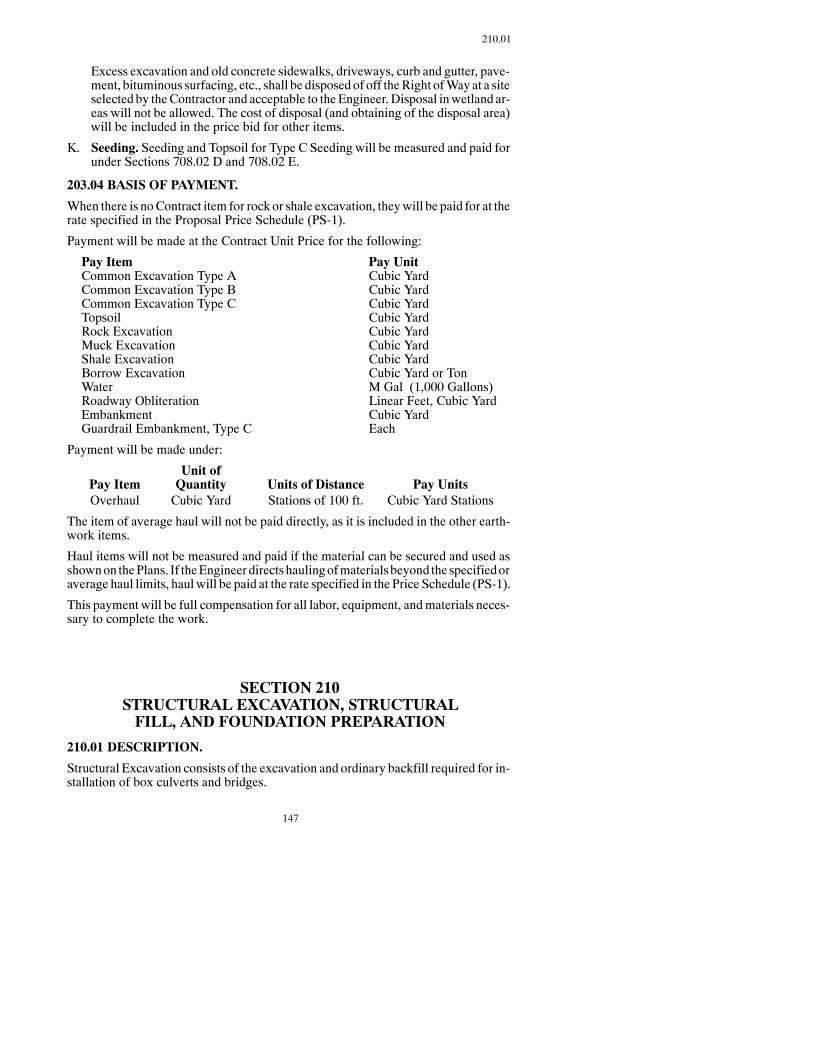
147
210.01
Excess excavation and old concrete sidewalks, driveways, curb and gutter, pave-ment, bituminous surfacing, etc., shall be disposed of off theRight ofWayat a siteselected by theContractor and acceptable to theEngineer. Disposal inwetland ar-eas will not be allowed. The cost of disposal (and obtaining of the disposal area)will be included in the price bid for other items.
K. Seeding. Seeding and Topsoil for Type C Seeding will be measured and paid forunder Sections 708.02 D and 708.02 E.
203.04 BASIS OF PAYMENT.
When there is noContract item for rock or shale excavation, theywill be paid for at therate specified in the Proposal Price Schedule (PS-1).
Payment will be made at the Contract Unit Price for the following:
Pay Item Pay UnitCommon Excavation Type A Cubic YardCommon Excavation Type B Cubic YardCommon Excavation Type C Cubic YardTopsoil Cubic YardRock Excavation Cubic YardMuck Excavation Cubic YardShale Excavation Cubic YardBorrow Excavation Cubic Yard or TonWater M Gal (1,000 Gallons)Roadway Obliteration Linear Feet, Cubic YardEmbankment Cubic YardGuardrail Embankment, Type C Each
Payment will be made under:
Unit ofPay Item Quantity Units of Distance Pay UnitsOverhaul Cubic Yard Stations of 100 ft. Cubic Yard Stations
The item of average haul will not be paid directly, as it is included in the other earth-work items.
Haul items will not be measured and paid if the material can be secured and used asshownon thePlans. If theEngineer directshaulingofmaterialsbeyond the specifiedoraverage haul limits, haul will be paid at the rate specified in the Price Schedule (PS-1).
This payment will be full compensation for all labor, equipment, andmaterials neces-sary to complete the work.
SECTION 210STRUCTURAL EXCAVATION, STRUCTURALFILL, AND FOUNDATION PREPARATION
210.01 DESCRIPTION.
Structural Excavation consists of the excavation and ordinary backfill required for in-stallation of box culverts and bridges.

148
210.01
Structural Fill shall consist of furnishing and placing select backfill material as shownon the Plans or as otherwise directed.
Foundation Preparation consists of site preparation for installation of a box culvert orbridge.
210.02 MATERIALS.
A. Ordinary Backfill.Material for ordinary backfill shall be approved compactiblesoil selected from structure excavation. Any additional material needed shall beapproved material obtained from borrow excavation.
B. Structural Fill.
1. Select Backfill. Select backfill shall be a well-graded mixture of stone frag-mentsor gravel, coarse sand, and fine sand, excludingscoriaandshale.Maxi-mum size and gradation shall be as specified.
2. Foundation Fill. Foundation fill material shall be CL 3 or CL 5 as specifiedin Section 816, unless otherwise noted.
210.03 CONSTRUCTION REQUIREMENTS.
The excavating, shoring, cofferdamming, sealing, and pumping for box culverts andbridges shall be done so the concrete is placed in a dry area free from standing or flow-ing water.
When a footing is placed on an excavated surface, the bottom of the excavation shallnot be disturbed. If disturbed, the area shall be scarified and recompacted with a me-chanical tamper. Final preparationof the foundationbed shall bemade just before con-crete placement. When foundation piles are used, the bottom of the excavation mayextend below the bottom of the footing to allow for heaving and placing backfill afterthe piles are driven. This extra excavation and backfill shall be at the Contractor’s ex-pense.
All suitable excavated material shall be used for backfilling, and the balance shall bestockpiled or disposed of at locations acceptable to the Engineer. All unsuitablemate-rial shall be disposed of and paid for according to Section 203.02 D.
After the unsuitable material has been excavated, foundation fill shall be placed in6-inchmaximum layers to the required elevation. Each layer shall be thoroughly com-pacted with mechanical tamping equipment. Water may be required to achieve satis-factory compaction and stability.
Backfill shall not be placed to a higher elevation on one side than on the other side of awall until the concrete has attained at least 70 percent of its design strength. If a walldependsona superstructure for support, backfill shall not beplaceduntil the falseworkfor the superstructure has been released. Concrete box culverts shall not be backfilleduntil the concrete has attained at least 70 percent of its design strength.
When there are separate structural and grading contracts, the Structural Contractorshall backfill box culverts to an elevation of 2 feet above the top of the box culvert, and

149
210.04 B
shall backfill bridges to the elevation shown on the Plans. The horizontal limits of thebackfill shall be as shown on the Plans. TheGradingContractor shall complete the re-maining backfill in conjunction with grading operations.
When a specified density is required, backfill shall be placed in horizontal layers notexceeding12 inches loosemeasurementandbeuniformlycompactedwithmechanicaltamping equipment to the specified density.
In non-load carrying areaswhere specified density is not required, the backfill shall beplaced in layers of not more than 6 inches, moistened or dried as required, and thor-oughly compacted with mechanical tamping equipment.
Special care shall be taken toprevent anywedging actionagainst the structure. Theuseof drop pile hammers, loaded or unloaded clam shells, or other similar equipment isprohibited for compacting backfill.
Backfill material deposited in water or adjacent to piers within the waterway shall bedeposited and compacted in a manner acceptable to the Engineer.
Sheet piling, bracing, forms, and rubbish shall be removed from the excavation beforethe backfill is started.
210.04 METHOD OF MEASUREMENT.
A. Structural Excavation. The unit of measure will be either by Cubic Yard orLump Sum, as specified on the Plans.
1. Channel Excavation.All excavation designated on the Plans as channel ex-cavation, including the excavation necessary to place riprap and aggregatecushion, and excavation necessary to flatten and shape the slopes to and be-yond the abutment locations.
2. ClassExcavation.WhenClass 1orClass 2Excavation ismeasuredandpaidfor by the Cubic Yard, the volume to be paid for will be that volume boundedby vertical planes located at either 1-1/2 feet outside of the footing, or2-1/2 feet outside of andparallel to thewall,whichever is greater, and the fol-lowing:
a. Class 1Excavation.All excavation above the datum line and outside thelimits of channel excavation, as designated on the Plans.
b. Class 2Excavation.All excavation below the datum line and outside thelimits of channel excavation, as designated on the Plans.
B. Foundation Preparation. The Unit of Measure will be Each for each structuralsite and, unless specified as separate pay items,will include thecost of performingthe following work items:
Clearing and GrubbingExcavationRemoval of Old Structures (or parts thereof as required)Construction and Removal of Shoring, Cribs, CofferdamsDewatering the Excavation

150
210.04 B
Concrete SealBackfillingDisposal of Surplus Material
Dewatering consists of removing water as needed to facilitate construction, andmay require intermittent or continuous operation of pumping equipment until theaffected construction activities in the dewatered area are completed.
Excavation shall include Channel Excavation, Class 1 Excavation, and Class 2Excavation unless these are specified as separate bid items.
C. Structural Fill.
1. Ordinary Backfill. Ordinary backfill will not be measured and the costsshall be included in the bid item “Excavation.”
2. Select Backfill.This itemwill bemeasured by the Cubic Yard in place. Thismeasured volumewill be increased by 25 percent to allow for shrinkage andto obtain the pay quantity.When select backfill is placed beyond the excava-tion limits, the pay quantity will be determined by computation using plandimensions and adding 25 percent for shrinkage.
3. Foundation Fill.This itemwill bemeasured by theCubicYard in place. Themeasured volumewill be increased by 25 percent to allow for shrinkage andto obtain the pay quantity.
210.05 BASIS OF PAYMENT.
Payment will be made at the Contract Unit Price for the following:
Pay Item Pay UnitChannel Excavation Lump Sum, Cubic YardClass 1 Excavation Lump Sum, Cubic YardClass 2 Excavation Lump Sum, Cubic YardFoundation Preparation EachFoundation Fill Cubic YardSelect Backfill Cubic Yard
This payment will be full compensation for all labor, equipment, andmaterials neces-sary to complete the work.
SECTION 216WATER
216.01 DESCRIPTION.
This item consists of applyingwater tomaterials being incorporated into constructionof items covered by the Contract.

151
230.02 A
Provisionsof thisSpecification shall not apply toPortlandCementmixingwater or forwatering seeded or sodded areas.
216.02 MATERIALS.
Water shall be furnished by the Contractor and shall be free of anymaterial which im-pedes its flow through the spraying device.
216.03 EQUIPMENT.
Equipment shall meet Section 151.03 A. Hauling units shall not exceed their licensedlegal weight limits.
216.04 CONSTRUCTION REQUIREMENTS.
Water shall be applied to the embankment, to constructionmaterials on the roadbed, tohaul roads, and to plant sites in sufficient quantity to secure andmaintain propermois-ture content or dust control.
216.05 METHOD OF MEASUREMENT.
Water will be measured in units of “M” Gallons (1,000 gallons). Water may be meas-ured in calibrated tanks, by weighing and converting to gallons at the rate of 8.33pounds per gallon, or by an approved metering device placed in the supply line. Themetering device shall be calibrated before use on the Project.
216.06 BASIS OF PAYMENT.
Payment will be made at the Contract Unit Price for the following:
Pay Item Pay UnitWater M. Gal.
This payment will be full compensation for all labor, equipment, andmaterials neces-sary to complete the work.
SECTION 230RESHAPING ROADWAY AND SUBGRADE PREPARATION
230.01 DESCRIPTION.
Thiswork consists of scarifying, shaping, compacting, andmaintaining the subgrade,or reshaping an existing roadway before constructing a base, or surface course.
230.02 CONSTRUCTION REQUIREMENTS.
A. Reshaping Roadway, Shoulders, and Inslopes.

152
230.02 A.1
1. Reshaping Roadway.All sod shall be removed from that portion of the ex-isting roadbed and slopes between the shoulder lines of the completed road-bed. The roadway, ditches, and slopes shall be reshaped to an elevation andcross section that meets the typical section shown on the Plan.
All soft and spongy material, rocks larger than 4 inches, roots and other for-eign matter brought to the surface shall be removed and disposed of underSection 203.02 D. All holes and depressions shall be filled and compactedwith approved material.
The subgrade shall be smooth, moistened or dried as necessary, and com-pacted as specified. Any defects in the subgrade shall be corrected accordingto these Specifications.
2. Shoulder Preparation. When included as a separate bid item, “ShoulderPreparation” consists of preparing the existing shoulders to receive a base orsurface course. All weeds, grass, dirt, and other objectionable material shallbe removed from the shoulders by blading, power brooms, or other meansapproved by the Engineer. Sod chunks or pieces of debris larger than36 square inches on any face shall be disposed of under Section 203.02 D.
3. Reshaping Inslopes. When shown as a separate bid item, “Reshaping In-slopes” consists of reshaping existing inslopes to form a smooth transitionbetween the finished shoulder and the existing inslope.
4. Topsoil. Topsoil shall be removed from inslopes and other seeded areaswhere reshaping will take place, and shall be stockpiled on the Right ofWayor other locations acceptable to the Engineer. Salvaged topsoil that is stock-piled within the clear zone must be stockpiled in a manner that is safely tra-versable. The stockpile must have slopes which are 4:1 or flatter if they arelocated within the clear zone. Topsoil shall be replaced according to Sec-tion 203.02 B.
On divided highways, topsoil removed frommedian inslopes shall be stock-piled at locations shown on the Plans or acceptable to the Engineer.
B. Subgrade Preparation.
1. General Requirements.
Thesubgrade shall be scarified, shaped, andcompacted to thedepth specifiedin the Plans, prior to the placement of the base section.
The subgrade shall be scarified with the use of a plow and disk to provide auniform section. The plow and disk shall conform to the requirement of Sec-tion 151. Rocks which interfere with trimming the subgrade, the subgradematerial, roots, and foreignmaterial brought to the surface, shall be disposedof under Section 203.02 D.
The moisture and density requirements will be specified in the Plans. If thespecified density and stability cannot be obtained by manipulating and dry-ing because of excessivemoisture, work shall be suspended to allow the sub-grade to recover its strength. No additional payments shall be made to the

153
230.02 B.4
Contractor due to the suspension of work. If the Engineer directs manipula-tion and drying below the depth specified in the Plans, paymentwill bemadeaccording to Section 104.03.
The subgrade shall be compacted in 6-inch lifts to the depth of specified sub-grade preparation. Special requirements for moisture density control will benoted in the Plans.
The subgrade elevations shall not vary fromany point bymore than 0.08 footfrom the prescribed elevation.
TheContractor shallmaintain the subgrade and take the necessary precautionsto protect the finished subgrade from damage. The Contractor shall ensurethat the subgrade has been graded to drain at the end of each day. The routingof traffic over the finished subgrade shall be limited to that which is essentialfor construction purposes. Any damage resulting from construction opera-tions shall be repaired at the expense of the Contractor.
Base or surface material shall not be placed until the subgrade has beenchecked and approved by the Engineer. The subgrade shall have the requiredstability and compactionduringplacement.No ruttingor displacement of theroadbed shall occur when the base material is placed on the subgrade.
TheDepartmentwill set appropriate stakes for use in shaping the subgrade tothe required section and the established grade. TheContractor shall preservethe line and grade stakes as long as they are needed.
Private drives, minor road approaches, and areas of irregular dimension orrestricted access shall be shaped and compacted to the required stabilitywithno specified density.
2. Subgrade Preparation Type A. This work shall meet Section 230.02 B.1.
3. Subgrade Preparation Type B. This work shall meet Section 230.02 B.1and the following:
Special requirements for moisture and density control will be noted on thePlans.
Before placing any base or surfacing material on the roadbed, the subgradeshall be brought to the required grade and cross section using a roadbedplaner conforming to Section 153.06. Grade control will be taken from thetaut string line erected parallel to the established grade line, except the Engi-neer may permit a base or surface course to be used as a grade reference fortrimming the shoulders. Taut string lines shall be erected andmaintained foroperating the automatic controls on the trimming equipment.
4. Subgrade Preparation Type A (Shoulders).When included as a separatebid item, “Subgrade Preparation Type A (Shoulders)” consists of removingsome or all of the existing base and surfacing from the shoulders, reshapingand recompacting the shoulder subgrade; and replacing and recompactingsome or all of the base or surface material removed. Specific requirementswill be as shown on the Plans.
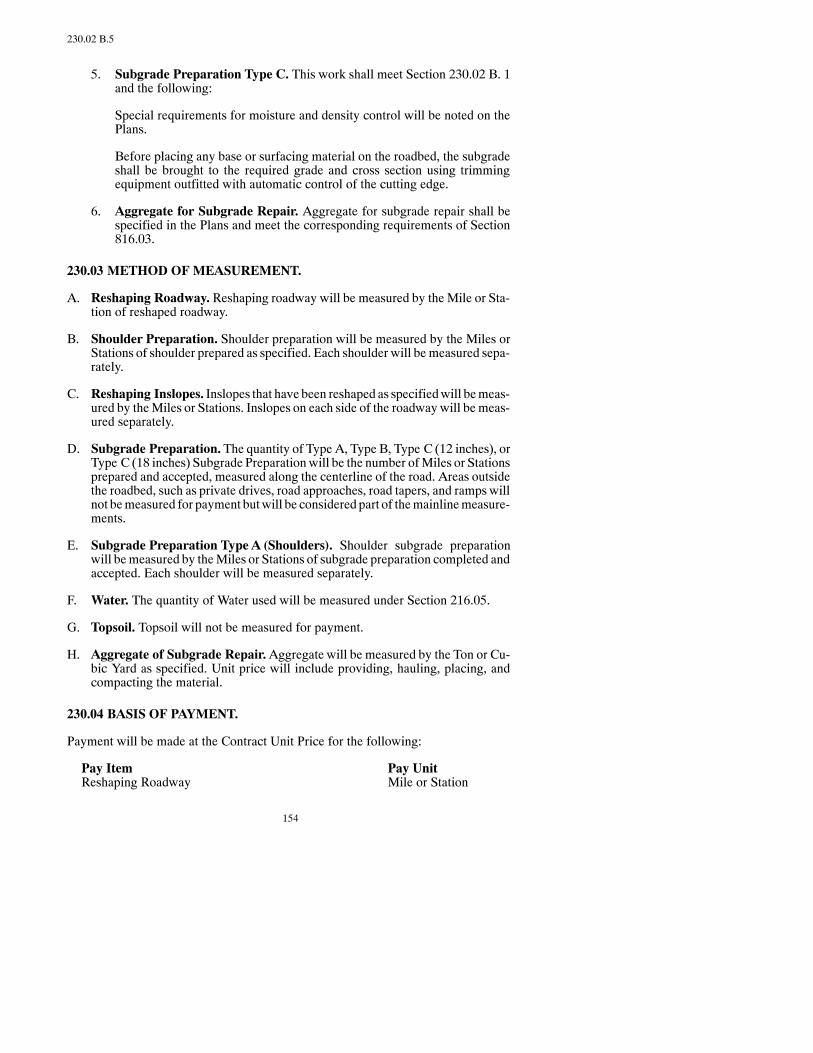
154
230.02 B.5
5. Subgrade Preparation Type C. This work shall meet Section 230.02 B. 1and the following:
Special requirements for moisture and density control will be noted on thePlans.
Before placing any base or surfacing material on the roadbed, the subgradeshall be brought to the required grade and cross section using trimmingequipment outfitted with automatic control of the cutting edge.
6. Aggregate for Subgrade Repair. Aggregate for subgrade repair shall bespecified in the Plans and meet the corresponding requirements of Section816.03.
230.03 METHOD OF MEASUREMENT.
A. Reshaping Roadway. Reshaping roadway will be measured by the Mile or Sta-tion of reshaped roadway.
B. Shoulder Preparation. Shoulder preparation will be measured by the Miles orStations of shoulder prepared as specified. Each shoulder will be measured sepa-rately.
C. Reshaping Inslopes. Inslopes that have been reshaped as specifiedwill bemeas-ured by theMiles or Stations. Inslopes on each side of the roadwaywill be meas-ured separately.
D. Subgrade Preparation. The quantity of Type A, Type B, Type C (12 inches), orType C (18 inches) Subgrade Preparation will be the number ofMiles or Stationsprepared and accepted, measured along the centerline of the road. Areas outsidethe roadbed, such as private drives, road approaches, road tapers, and ramps willnot bemeasured for payment butwill be considered part of themainlinemeasure-ments.
E. Subgrade Preparation Type A (Shoulders). Shoulder subgrade preparationwill bemeasured by theMiles or Stations of subgrade preparation completed andaccepted. Each shoulder will be measured separately.
F. Water. The quantity of Water used will be measured under Section 216.05.
G. Topsoil. Topsoil will not be measured for payment.
H. Aggregate of Subgrade Repair.Aggregate will be measured by the Ton or Cu-bic Yard as specified. Unit price will include providing, hauling, placing, andcompacting the material.
230.04 BASIS OF PAYMENT.
Payment will be made at the Contract Unit Price for the following:
Pay Item Pay UnitReshaping Roadway Mile or Station

155
234.03
Subgrade Preparation Type A Mile or StationSubgrade Preparation Type B Mile or StationSubgrade Preparation Type C (12 inches) Mile or StationSubgrade Preparation Type C (18 inches) Mile or StationShoulder Preparation Mile or StationReshaping Inslopes Mile or StationSubgrade Preparation Type A (Shoulders) Mile or StationAggregate for Subgrade Repair Ton or Cubic YardWater M. Gal.
Full compensation for excavation, removal, and disposal of undesirable subgradema-terial will be paid according to Section 104.03.
Excavation and hauling ofmaterial from one point to another on the roadbed to adjustthe grade line will be paid according to Section 104.03.
The cost of removing, stockpiling, and replacing topsoil along the reshaped inslopeswill be included in the prices bid for the reshaping and subgrade preparation items.
This payment will be full compensation for all labor, equipment, andmaterials neces-sary to complete the work.
SECTION 234STABILIZED SUBGRADE
234.01 DESCRIPTION.
This work consists of treating the top layer of subgrade with lime or lime-fly ash.
234.02 MATERIALS.
Materials shall meet the following:
Item SectionLime 804.02Fly Ash 820Water 812
234.03 EQUIPMENT.
Equipment shall meet the following:
Item SectionGeneral 151.01Water-Hauling Equipment 151.03 AMaterial Hauling Equipment 151.03 BTow-Type Pneumatic-Tired Rollers 151.02 ASelf-Propelled Pneumatic-Tired Rollers 151.02 B

156
234.04
234.04 CONSTRUCTION REQUIREMENTS.
The roadbed shall be shaped to the cross section shown on the Plans. The roadbedma-terial shall be scarifiedor disked to a depth of 6 inches, 12 inches, 18 inches, 24 inches,or more as required. Any work that the Engineer requires to be done below a 24-inchdepthwill be paid according to Section 104.03. The bottom6 inches of the scarified ordisked depth shall remain on the roadway, mixedwith lime, and worked in place. Thesubgrade shall be replaced in 6-inch lifts, aerated,mixedwith lime or lime-fly ash, andrecompacted as directed by the Engineer. Section 104.03 B will not apply to lime orlime-fly ash. Any wet or unstable materials below the scarified section shall be cor-rected as directed by the Engineer.
A. Spreading.The limeor lime-fly ash shall be spread bydry application or slurry atthe rates shownon thePlans.The limeand flyashmaybeapplied together or sepa-rately, provided the lime is applied before the fly ash. Both lime and fly ash shallbe distributed uniformlywithout loss ofmaterial bywindor other causes. Limeorfly ash shall not be applied by dry applicationwhen thewind is 15mph or greater.
Slurry shall be used in areas adjacent to residential or other developed areas so thelime or lime-fly ash does not damage, discomfort, or be an inconvenience to pub-lic or private property. The lime or lime-fly ash shall be premixed with water inapproved agitating equipment in proportions so that the “Dry-Solids Content” isat least 30percent byweight. Limeor lime-fly ashandwatermaybe similarlypro-portioned in distributing equipment, provided the equipment contains approvedmetering devices which accuratelymeters the quantity of water, lime, or lime-flyash into the distributing tank to provide positive controls for proper proportioningof the mixture.
All distributing equipment shall provide continuous and adequate agitation untilthe slurry is applied to the roadbed. The slurry shall be applied through pressur-ized distributing spray bars. Adequate means of accurately determining distribu-tion of lime or lime-fly ash on each area shall be provided. Each distributing unitshall be provided with a metering device which accurately determine the “Dry-Solids Content” applied to any area, based on the percentage of lime or lime-flyash in the slurry. The application of lime or lime-fly ashmay also be controlled byweight or bymeasuringandconverting toweight each loadorpartial loadapplied,and basing the dry-solids content on the percentage of lime or lime-fly ash in theslurry.
The total application of lime or lime-fly ash ordered shall be attained by succes-sive passes of the distributing equipment over a measured area.
The slurrymaybeapplieddirectly to the scarifiedordiskedsubgrade, providednoloss of lime or lime-fly ash slurry is evident and uniform distribution into the soilcan be made.
B. Mixing.The limeor lime-flyash shall be thoroughlymixedwith thematerial tobeprocessed with enough water added to the mixture to maintain not less than opti-mummoisture content.Mixing shall be accomplishedby theuse of a rotarymixer.It shall be mixed so that 100 percent of the material passes a one inch sieve. If thematerial does not readily mix with the lime or lime-fly ash, it shall be thoroughlymixed, brought to the proper moisture content, and left to cure 24 to 48 hours.
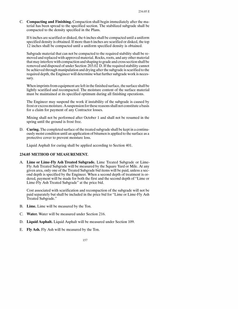
157
234.05 E
C. Compacting and Finishing. Compaction shall begin immediately after the ma-terial has been spread to the specified section. The stabilized subgrade shall becompacted to the density specified in the Plans.
If 6 inches are scarified or disked, the 6 inches shall be compacted until a uniformspecified density is obtained. If more than 6 inches are scarified or disked, the top12 inches shall be compacted until a uniform specified density is obtained.
Subgrade material that can not be compacted to the required stability shall be re-moved and replacedwith approvedmaterial. Rocks, roots, and any othermaterialthatmay interferewith compactionand shaping to grade and cross section shall beremoved and disposed of under Section 203.02 D. If the required stability cannotbe achieved throughmanipulation and drying after the subgrade is scarified to therequired depth, the Engineer will determinewhat further subgradework is neces-sary.
When imprints fromequipment are left in the finished surface, the surface shall belightly scarified and recompacted. The moisture content of the surface materialmust be maintained at its specified optimum during all finishing operations.
The Engineer may suspend the work if instability of the subgrade is caused byfrost or excessmoisture.Asuspension for these reasons shall not constitute abasisfor a claim for payment of any Contractor losses.
Mixing shall not be performed after October 1 and shall not be resumed in thespring until the ground is frost free.
D. Curing.The completed surface of the treated subgrade shall be kept in a continu-ouslymoist condition until an application of bitumen is applied to the surface as aprotective cover to prevent moisture loss.
Liquid Asphalt for curing shall be applied according to Section 401.
234.05 METHOD OF MEASUREMENT.
A. Lime or Lime-Fly Ash Treated Subgrade. Lime Treated Subgrade or Lime-Fly Ash Treated Subgrade will be measured by the Square Yard or Mile. At anygiven area, only one of the Treated Subgrade bid items will be paid, unless a sec-ond depth is specified by the Engineer. When a second depth of treatment is or-dered, payment will be made for both the first and the second depth of “Lime orLime-Fly Ash Treated Subgrade” at the price bid.
Cost associated with scarification and recompaction of the subgrade will not bepaid separately but shall be included in the price bid for “Lime or Lime-Fly AshTreated Subgrade.”
B. Lime. Lime will be measured by the Ton.
C. Water.Water will be measured under Section 216.
D. Liquid Asphalt. Liquid Asphalt will be measured under Section 109.
E. Fly Ash. Fly Ash will be measured by the Ton.
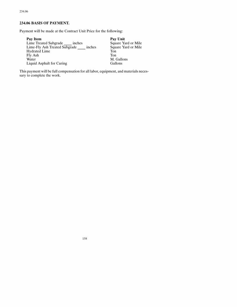
158
234.06
234.06 BASIS OF PAYMENT.
Payment will be made at the Contract Unit Price for the following:
Pay Item Pay UnitLime Treated Subgrade ____ inches Square Yard or MileLime-Fly Ash Treated Subgrade ____ inches Square Yard or MileHydrated Lime TonFly Ash TonWater M. GallonsLiquid Asphalt for Curing Gallons
This payment will be full compensation for all labor, equipment, andmaterials neces-sary to complete the work.

159
SECTION 300BASES

160

161
SECTION 302SALVAGED BASE COURSE, AGGREGATE BASE COURSE,
OR AGGREGATE SURFACE COURSE
302.01 DESCRIPTION
302.02 MATERIALSA. Aggregate or Salvaged MaterialB. Acceptance
302.03 EQUIPMENT
302.04 CONSTRUCTION REQUIREMENTSA. Pit OperationsB. Subgrade PreparationC. Depositing and LaydownD. CompactionE. Application of WaterF. Surface ToleranceG. LimitationsH. Maintenance of Completed Course
302.05 METHOD OF MEASUREMENT
302.06 BASIS OF PAYMENT
SECTION 304PERMEABLE STABILIZED BASE COURSE
304.01 DESCRIPTION
304.02 MATERIALSA. AggregateB. AcceptanceC. AsphaltD. Portland Cement
304.03 EQUIPMENT
304.04 CONSTRUCTION REQUIREMENTSA. General
1. Subbase2. Finished Surface3. Traffic4. Pavement Edge5. Placement6. Tolerance in Base Thickness
B. Asphalt Stabilized Base1. Material Production and Placement2. Compaction3. Weather Limitations
C. Portland Cement Treated Base1. Material Production2. Placement
304.05 METHOD OF MEASUREMENT
304.06 BASIS OF PAYMENT

162
SECTION 306BLENDED BASE COURSE
306.01 DESCRIPTION
306.02 MATERIALSA. Blended MaterialB. AggregateC. Acceptance
1. Aggregate306.03 EQUIPMENT
306.04 CONSTRUCTION REQUIREMENTSA. Pit OperationsB. Adding Corrective MaterialC. Aggregate Placement and BlendingD. Blending DepthE. Placement and Compaction of Blended MaterialF. Soft AreasG. Application of WaterH. Surface ToleranceI. LimitationsJ. Maintenance of Completed Courses
306.05 METHOD OF MEASUREMENTA. Blended Base CourseB. Remove and Relay Blended Base CourseC. AggregateD. Water
306.06 BASIS OF PAYMENT

163
302.02 B.2
SECTION 302SALVAGED BASE COURSE, AGGREGATE BASE COURSE,
OR AGGREGATE SURFACE COURSE
302.01 DESCRIPTION.
This work consists of furnishing and placing one or more courses of aggregate or sal-vaged materials on a prepared foundation.
302.02 MATERIALS.
A. Aggregate or Salvaged Material. Aggregates shall meet Section 816 for theclass of aggregate specified. Salvaged material shall meet the specifications ofSection 817.
B. Acceptance. Refer to the Department’s Field Sampling and Testing Manual.
1. Aggregate Base.When the aggregate does not meet the gradation specifiedfor all required samples, a reduction in the Contract Unit Price will be made.If the aggregate fails to meet the specified gradation on one or more sieves,the reduction will be the sum of the deductions as calculated below.
Unit Price Reduction: Percent of Deduction = 5× percent of deviation fromrange limits.
If material is produced that deviates from the specified gradation for 2 con-secutive lots, incorporation of additional material into the work will not beallowed until theContractor takes the necessary corrective action tomeet thespecifications.
2. Salvaged Base. If the average exceeds the specified limits for shale, the unitprice for aggregate will be adjusted according to Section 302.06. If the aver-age exceeds the specified limits for plasticity index or fractured faces, theContractor shall correct the stockpile so the material meets specifications.
Bitumen-content testing of Contractor-supplied Salvaged Base will be per-formed on lots of 10,000 tons or fraction thereof for the final lot. If the aver-age of the 3 extraction results is greater than 3.5 percent, a reduction in theunit price will be made according to the formula below. If the average per-centage of bitumen exceeds 4.0 percent, the material will be rejected.
Unit Price Reduction:Percent Reduction = 20 × 0.1 percent above the allowable bitumen content(i.e. a 2 percent reduction per 0.1 percent above the allowable)
When the average of the test results specified in Section 302.02 shows a largerpercentage of shale than themaximum allowable specified, a 1 percent reduction

164
302.02 B.2
in the unit pricewill bemade for each 0.2 percent above the allowable percentage.If the percentage of shale exceeds the allowable limit by 3 percent or more, thematerial will be rejected unless the material is accepted under Section 105.07.
302.03 EQUIPMENT.
Equipment shall meet the following:
Item SectionGeneral 151.01Tow-Type Pneumatic-Tired Rollers 151.02 ASelf-Propelled Pneumatic-Tired Rollers 151.02 BVibratory Rollers 151.02 DVibratory Sheeps Foot/Pad Foot/Extended Pad Foot Rollers 151.02 FWater-Hauling Equipment 151.03 AMaterial-Hauling Equipment 151.03 B
302.04 CONSTRUCTION REQUIREMENTS.
A. Pit Operations. Stripping of the pit and pit operations shall be according to Sec-tion 106.02 and other Contract requirements to produce an aggregatemeeting thespecification for the class specified.
B. Subgrade Preparation. Subgrade preparation shall be completed according toSection 230.02 B.
C. Depositing and Laydown.The aggregate shall be deposited, spread, and shapedso the moist and compacted course conforms to the required grade and cross sec-tion within the tolerance specified in this Section.
D. Compaction.Compaction shall be carried out simultaneously with laydown op-erations.The compacteddepthof a single course shall not exceed6 inches. If geo-textile fabric is specified, Section 709 will govern compaction requirements. Allequipment shall beoperated toproduceuniformdensity throughout the entire sec-tion.Pneumatic-tired rollersof the type specified inSection151shallbeused.Thedesireddegree of compactionwill be acceptablewhen the surface is tightly boundand shows no rutting or displacement under roller operation.
E. Application of Water.Water shall be appliedaccording toSection 216asneededto secure required results.
F. Surface Tolerance. The surface of the completed base shall be tightly bound,smooth, and uniform; and conform to the cross section and grade specified.
Surface tolerance Type A shall be used unless specified.
1. Surface tolerance TypeA.The finished surface shall not vary from the pre-scribed cross section elevation bymore than 0.08 feet. The longitudinal pro-file shall not vary by more than 0.08 feet from the grade line established bythe Engineer.
2. SurfaceToleranceTypeB.Trimming equipmentwith automatic grade con-trols shall be usedwhen surface toleranceTypeB is specified. Motor graders

165
302.06
may be used as trimming equipment. The automatic grade controls shall ad-just for the cross slope and longitudinal profile. The automatic grade controlsshall produce a finished surface that does not vary from the prescribed crosssection elevation or grade line by more than 0.04 feet, as established by theEngineer.
3. SurfaceToleranceTypeC.Trimmingequipmentwith automatic grade con-trols shall be usedwhen surface toleranceTypeC is specified. The automaticgrade controls shall adjust for the cross slope and longitudinal profile.Motorgraders shall not be used as trimming equipment. Roadbed planers shall beused as trimming equipment as specified in Section 153.06. Grade controlshall be taken from a taut string line erected parallel to the grade line estab-lished by the Engineer. The Engineer may permit a base or surface course tobe used as a grade reference for trimming the shoulders. The taut string linesshall be erected andmaintained so the automatic controls produce a finishedsurface that doesnotvary fromtheprescribedcross sectionelevationbymorethan 0.04 feet from the grade line established by the Engineer.
G. Limitations. The quantity of aggregate or salvaged material permitted in wind-rows on roadways open to traffic, shall not exceed three miles. The aggregate orsalvaged material shall be layed within 72 hours after being placed in the wind-row.
Aggregate or salvaged material shall not be placed on a frozen subgrade.
H. Maintenance of Completed Courses. When the Contract includes successivebase courses or base and surface courses, each course shall be maintained in asmooth and compacted condition until the succeeding course is placed.
302.05 METHOD OF MEASUREMENT.
A. Aggregate or Salvaged Base or Surface Course.Measurement will be by theTon or Cubic Yard, as specified.
B. Water.Measurement will be made according to Section 216.
302.06 BASIS OF PAYMENT.
Payment will be made at the Contract Unit Price for the following:
Pay Item Pay UnitAggregate or Salvaged Base or Surface Course Ton or Cubic YardWater “M Gal”
This payment will be full compensation for all labor, equipment, andmaterials neces-sary to complete the work.
When a mixture is subject to pay reduction as described in Section 302.02, the BidPrice will be reduced by the sum of the price adjustments.

166
304.01
SECTION 304PERMEABLE STABILIZED BASE COURSE
304.01 DESCRIPTION.
This work consists of constructing a permeable stabilized base coursemixed in a cen-tral plant and placed on a prepared subbase. The Contractor shall have the option ofusing Portland Cement or Asphalt Cement as a stabilizing agent to stabilize the basecourse.
304.02 MATERIALS.
A. Aggregate. The aggregate shall be a Class 7 aggregate as specified in Section816.03.
B. Acceptance. Refer to the Department’s Field Sampling and Testing Manual.
When the aggregate does notmeet the gradation specified, a reduction in theCon-tractUnit Pricewill bemade. If the aggregate fails tomeet the specified gradationon one or more sieves, the reduction will be the sum of the deductions as calcu-lated below.
Unit Price Reduction:Percent of Deduction = 5 × percent of deviation from range limits.
Ifmaterial is produced that deviates from the specifiedgradation for twoconsecu-tive lots incorporation of additionalmaterial into theworkwill not be allowed un-til the Contractor takes the necessary corrective action tomeet the specifications.
If the average of three lots exceeds the specified limits for shale, the unit price foraggregate will be adjusted according to Section 302.02. If the average does notmeet the specified limits for fractured faces, theContractor shall correct the stock-pile so the material meets specifications.
C. Asphalt. The asphalt cement shall be a PG asphalt meeting the requirements ofSection 818.02 A.3.
Thebitumen shall be added to the aggregate uniformlyat a rate of 2-1/2 percent byweight of the mix.
If the daily cutoff for the asphalt cement, as determined on theMixBitumenCutoffReport, deviates from the target percentage specified bymore than 0.24 percentagepoints, the pay factor will be determined as specified in Section 408.05 B.1.
D. Portland Cement. The Portland Cement shall meet the requirements of Section804.01.

167
304.04 A.5
The PortlandCement content shall be 200 pounds per cubic yard. Batching of thecement shall be according to Section 802.04B.Aggregates and bulk cement shallbe proportionedby automatic batching equipment according toSection 153.01B.
304.03 EQUIPMENT.
Equipment shall meet the following:
Item SectionGeneral 151.01Rollers 151.02 CMaterial Hauling Equipment 151.03 BBituminous Pavers 151.04Scales 151.07Hot Bituminous Equipment 152P.C.C. Equipment 153Roadbed Planer 153.06
304.04 CONSTRUCTION REQUIREMENTS.
A. General.
1. Subbase.Beforeplacing thepermeable base, the subbase shall be trimmed tothe requiredgrade andcross sectionbya roadbedplaner.The finishedsurfaceof the subbase shall not vary by more than 0.04 foot from the prescribedelevation.
A prime coat shall be applied to establish an impermeable layer below thepermeable base. The prime coat shall be allowed to cure a minimum of24 hours before the permeable base is placed.
2. Finished Surface. The surface of the permeable base shall be smooth anduniform, and shall not vary bymore than 0.04 foot from the prescribed eleva-tion. Trimming of the permeable basewill not be permitted. Care shall be ex-ercised to prevent contamination of the permeable base. Procedures thatmight produce fine material that would tend to clog or reduce drainage willnot be permitted. Permeable base which, in the opinion of the Engineer, hasbeen contaminated shall be removed and replaced at the Contractor’s ex-pense.
3. Traffic.Hauling on the permeable base will not be allowed. Traffic over thepermeable base will be limited to the minimum necessary for succeeding oradjacent work. Damage to the permeable base shall be repaired promptly atthe Contractors expense.
4. Pavement Edge. The outlet edge of the permeable base shall be kept open(daylighted) until the edge drain is placed so that water is free to exit.
5. Placement. The permeable base shall be placed in one lift at the specifiedthickness. The base will be placed with a mechanical spreader, except whenplacing the base in small areas that are not accessible to large equipment. Inthese areas the base may be hand placed and compacted with mechanical

168
304.04 A.5
hand tampers. Themechanical spreader shall utilize automatic controls witha stringline to control the longitudinal profile.
If approved by the Engineer, the permeable base may be placed without thestabilizing agent in small areas that are formed by hand.
6. Tolerance inBaseThickness.Refer to theDepartment’sFieldSamplingandTesting Manual.
If the permeable base placed has an average thickness in excess of that speci-fied, additional paymentwill not bemade. If the average pavement thicknessis deficient bymore than 1 inch, the base will be removed and replaced at theContractors expense. If deficient by less than 1 inch in thickness, price ad-justmentswill bemade to theContractUnit Price for each lot of 4,500 squareyards as provided in the following table:
Deficiency in Pay FactorThickness (Inches)0.0 to 0.25 1.000.26 to 0.50 0.900.51 to 0.75 0.700.76 to 1.00 0.50
B. Asphalt Stabilized Base.
1. Material Production and Placement. The permeable base shall be pro-duced at a central hotmix plant according to Section 408.04 E and 408.04 F,paragraph 1. Thematerial produced shall be placedwith a bituminous paver.
2. Compaction. Compaction of the permeable base shall be according to Sec-tion 302.04D. except the roller shall be a 10-ton, double drum, steel-wheeledroller. No vibration will be allowed. The Contractor is advised that it may benecessary to permit the permeable base to cool sufficiently before compac-tion rolling to prevent rutting and shoving. Cooling to 150°F. may be ap-propriate, but in no case shall the mix be less than 110°F. at time of compac-tion. Water may not be used to hasten the cooling process.
3. Weather Limitations.Weather limitations shall be as specified in Section408.04 M.1.
C. Portland Cement Treated Base.
1. Material Production. The Permeable base shall be mixed at a stationarymixing plant capable of producing a uniformmixture and shall be equippedwith feeding and/or weighing devices that are capable of proportioning themixture as specified.
The water/cement ratio shall provide for 100 percent cement (paste) cover-age of aggregate. The intent is to add theminimumamount ofwater to obtaina uniform workable mix.
2. Placement.The cement stabilized base shall be placedwith a slip formpaveror a mechanical spreader capable of placing the material in one layer. The
169
306.02 A
paver or spreader shall be equipped with automatic grade control that main-tains the proper elevation at both sides by: (1) controlling the elevation of oneside and the slope, or (2) controlling the elevation of each side independently.The grade reference shall be an erected string line or other approvedmethod.
The cement stabilized base shall be consolidatedwith surface pan typevibra-tors. The frequency of the surface pan type vibrators shall not be less than4000 impulses per minute, unless modified by the Engineer.
The cement stabilized base shall be allowed to cure a minimum of 48 hoursbefore placement of the surface course. Exceptions may be made, with theEngineer’s approval, in areaswhere immediate access is necessary to accom-modate traffic.
Weather limitations shall be as specified in Section 602.03 G.3.
When placing the stabilized base at bridge ends, ramp tapers or other areaswhere placement is not practicalwith amechanical spreader, the basemateri-al may be placed with a loader and compacted with a 10 ton steel wheeledroller in the static mode.
304.05 METHOD OF MEASUREMENT.
Permeable StabilizedBaseCourse.Permeable StabilizedBase shall bemeasured bythe square yard placed, and accepted by the Engineer.
304.06 BASIS OF PAYMENT.
Theacceptedquantityof permeable stabilizedbasewill bepaid for at the contract pricebid per square yard. The price shall be full compensation for all materials (includingthe asphalt or portland cement binder), equipment, labor, and incidentals required toconstruct this item of work as specified.
Pay Item Pay UnitPermeable Stabilized Base Course Ton or Cubic Yard
SECTION 306BLENDED BASE COURSE
306.01 DESCRIPTION.
This work consists of blending and placing the existing aggregate base, existing bitu-minous surfacing and possibly one or more courses of aggregate into a uniform basematerial.
306.02 MATERIALS.
A. Blended Material. The blended material shall have 97 to 100 percent passing a2-inch sieve and 90 to 100 percent passing a 1-1/2-inch sieve.
170
306.02 B
B. Aggregate. The aggregate shall meet Section 816 for the class of aggregatespecified.
C. Acceptance.
1. Aggregate. Refer to the Department’s Field Sampling and Testing Manualfor sampling procedures.
When the aggregate does not meet the gradation specified, a reduction in theContract Unit Price will be made. If the aggregate fails to meet the specifiedgradation on1 ormore sieves, the reductionwill be the sumof the deductionsas calculated below.
Unit Price Reduction:Percent of Deduction = 5 × percent of deviation from range limits
If material is produced that deviates from the specified gradation for two con-secutive lots incorporation of additional material into the work will not be al-lowed until the Contractor takes the necessary corrective action to meet thespecifications.
If the average of the three samples exceeds the specified limits for shale, theunit price for aggregate will be adjusted according to Section 302.06. If theaverage exceeds the specified limits for plasticity index or fractured faces,theContractor shall correct the stockpile so thematerialmeets specifications.
306.03 EQUIPMENT.
Equipment shall meet the following:
Item SectionGeneral 151.01Tow-Type Pneumatic-Tired Rollers 151.02 ASelf-Propelled Pneumatic-Tired Rollers 151.02 BVibratory Sheeps Foot/Pad Foot/Extended Pad Foot Rollers 151.02 F
Water-Hauling Equipment 151.03 AMaterial-Hauling Equipment 151.03 BMining/Blending Machine 151.08
306.04 CONSTRUCTION REQUIREMENTS.
A. Pit Operations. Stripping of the pit and pit operations shall be according to Sec-tion 106.02 and other Contract requirements to produce an aggregatemeeting thespecification for the class specified.
B. Adding Corrective Material.When a combination of materials is required toproduce theclassof aggregate specified, the aggregatemaybeblendedat thepit oron the road to produce the specified material.
C. AggregatePlacementandBlending.When“BlendedBaseCourse” is specified,the aggregate supplied to be blendedwith the existingmaterial will be placed and

171
306.04 E
compacted on the roadway to plan cross slope and to a longitudinal profile ap-proved by the Engineer prior to blending. It is intended for the Contractor to usemining/blending equipment that rides on the existing surface. If the Contractorelects to use equipment that rides on the subgrade, the Contractor shall assure theequipment has sufficientweight distribution to prevent rutting or displacement ofthe subgrade below the blendedmaterial.Anydamage causedby theContractor’sequipment riding on the subgrade shall be repaired at the Contractor’s expense.
When “Remove and Relay Blended Base Course” is specified, the Contractormay elect to blend thematerial on or off the roadway. The use of amotor grader toblend the material will not be permitted. The Contractor must prove to the Engi-neer that the process used to blend thematerialwill provided a uniformly blendedbase course.
D. Blending Depth. The existing asphalt pavement depth varies. The pavementdepths shown in the plans are from cores taken at specified locations. Primed ag-gregate and bituminous treated base (if present) are not included in the pavementdepth. The actual pavement depths at other locationsmay vary. The Contractor isresponsible for interpreting the pavement depths and including all costs in the bidprice to process the required depth of existing pavement and existing aggregate.
When“BlendedBaseCourse” is specified, theContractor shall blend to: thedepthshown in theplansor, if thedepth shown in theplans is not great enough toprocessall of the existing surfacing, bituminous treated base (where present), and the ex-isting base, the blending depth shall be increased to the lesser of the followingdepths:
1. A depth great enough to process all of the supplemental aggregate, existingsurfacing and bituminous treated base (where present).
2. Aminimumof 18 inches,measured from top of supplemental compacted ag-gregate. The distance between the exiting asphalt material notmined and thenew pavement (asphalt or concrete) shall be a minimum of 18 inches.
During the blending operation theContractor shall physically dig down, approxi-mately every 500 feet (each pass), to check the blending depth and visually verifythe full depth of bituminous pavement has been blended without contaminationfrom the subgrade.
When “Remove andRelayBlendedBaseCourse” is specified, and if theContrac-tor elects to blend the material off the roadway, the entire depth of asphalt pave-ment shall be removed and blended with the aggregate specified.
E. Placement andCompaction ofBlendedMaterial.After blending, theContrac-tor shall place the blended material as shown in the Plans. The blended materialshall be uniform in gradation and compacted to produce a uniform densitythroughout the entire section. If the material is deficient in moisture content, itshall be moistened to the degree necessary to attain compaction.
Compaction shall be carried out simultaneously with lay down operations. Thevibratory sheeps foot/pad foot/extended pad foot roller shall be used to obtaincompaction until the feet/pads ride up close to the surface of the blended base.Af-ter this, the road top shall be compactedwith a pneumatic roller until the surface is

172
306.04 E
tightly bound and shows no sign of rutting or displacement under the compactionoperations or traffic. Vibratory sheeps foot/pad foot/extended pad foot and pneu-matic tired rollers of the type specified in Section 151 shall be used.
F. Soft Areas. Unstable areas, as determined by the Engineer, that appear after theblendedbase has been compacted shall be repaired by theContractor. If the unsta-ble areas are due to poor compaction of the blended base, the Contractor will re-work the blended base to obtain adequate compaction. The cost of reworking theblended base will be included in the item “Blended Base Course.”
If theunstableareasaredue to the subgrade, theEngineermaydirectmanipulationanddrying of the subgrade. Payment for thisworkwill be in accordancewithSec-tion 104.03 of the Standard Specifications.
G. Application ofWater.Water shall be applied according to Section 216 as neededto secure required results.
H. Surface Tolerance. The surface of the completed base shall be tightly bound,smooth, uniform, and conform to the cross section and grade specified. The sur-face shall be finished using a Surface Tolerance Type B, as specified in Section302.04 F.
I. Limitations. The quantity of aggregate or blended material permitted in wind-rows on roadways open to traffic, shall not exceed three miles. The aggregate orblendedmaterial shall be layedwithin 72hours after being placed in thewindrow.
Aggregate or blended material shall not be placed on a frozen subgrade.
J. Maintenance of Completed Courses.When the Contract includes successivebase courses or base and surface courses, each course shall be maintained in asmooth and compacted condition until the succeeding course is placed.
306.05 METHOD OF MEASUREMENT.
A. BlendedBaseCourse.Measurement andpayment of the bid item“BlendedBaseCourse” will be by the Square Yard based on the width of the existing asphaltpavement from the outside edge of the slough to the outside edge of the slough.
B. RemoveandRelayBlendedBaseCourse.Measurement andpayment of the biditem “Remove and Relay Blended Base Course” will be by the Ton or SquareYard.When paid by the Square Yard the quantity will be determined by thewidthof the existing asphalt pavement from the outside edge of the slough to the outsideedge of the slough.
C. Aggregate. Measurement will be by the Ton or Cubic Yard, as specified.
D. Water. Measurement will be made according to Section 216.

173
306.06
306.06 BASIS OF PAYMENT.
Payment will be made at the contract Unit Price for the following:
Pay Item Pay UnitAggregate Ton or Cubic YardWater “M Gal”Blended Base Course Square YardRemove and Relay Blended Base Course SquareYard or Ton
This payment will be full compensation all labor, equipment, andmaterials necessaryto complete the work as required.
When a pay reduction, as described in Section 302.02 B, is applicable, the Bid Pricewill be reduced by the sum of the price adjustments.

174

175
SECTION 400BITUMINOUS PAVEMENTS

176
177
SECTION 401PRIME, TACK, OR FOG COAT
401.01 DESCRIPTION
401.02 MATERIALSA. BitumenB. Blotter Material
401.03 EQUIPMENT
401.04 CONSTRUCTION REQUIREMENTSA. Preparation of SurfaceB. Application of BitumenC. Application of Blotter MaterialD. Maintenance and Opening to TrafficE. Limitations
401.05 METHOD OF MEASUREMENT
401.06 BASIS OF PAYMENT
SECTION 402COLD BITUMINOUS PAVEMENT
402.01 DESCRIPTION
402.02 MATERIALSA. BitumenB. Aggregate.
402.03 EQUIPMENT
402.04 CONSTRUCTION REQUIREMENTSA. Pit OperationsB. Conditioning Existing SurfaceC. Heating of BitumenD. Hauling and Mixing AggregatesE. Mixing of Aggregates and Bitumen
1. General2. Blade Mix3. Traveling Mixer4. Stationary Plant
F. Spreading and FinishingG. CompactionH. Completed SurfaceI. Maintenance of Completed SurfaceJ. Limitations
402.05 METHOD OF MEASUREMENT
402.06 BASIS OF PAYMENT
SECTION 403STOCKPILED HOT BITUMINOUS MIX
403.01 DESCRIPTION

178
403.02 MATERIALSA. BitumenB. Aggregate
403.03 EQUIPMENT
403.04 CONSTRUCTION REQUIREMENTSA. Pit Operations and Stockpiling of MaterialB. Preparation of Bituminous MaterialC. Preparation of AggregateD. Mixing
403.05 METHOD OF MEASUREMENT
403.06 BASIS OF PAYMENT
SECTION 405REMOVE AND SALVAGE BITUMINOUS PAVEMENT
405.01 DESCRIPTION
405.02 CONSTRUCTION REQUIREMENTSA. Prepare Stockpile SiteB. StockpilingC. Restore Stockpile SiteD.. Remove and Salvage Bituminous Surfacing
405.03 METHOD OF MEASUREMENT
405.04 BASIS OF PAYMENT
SECTION 407HOT RECYCLED BITUMINOUS PAVEMENT
407.01 DESCRIPTION
407.02 MATERIALSA. BitumenB. Salvaged Bituminous MaterialC. Virgin AggregateD. Recycling Agent
407.03 EQUIPMENTA. GeneralB. Recycling Plant
407.04 CONSTRUCTION REQUIREMENTSA. Processing Salvaged MaterialB. Pit Operations and Stockpiling of AggregateC. Prepare Stockpile SitesD. StockpilingE. Restore Stockpile SiteF. Mix Design

179
G. Heating of BitumenH. Preparation of Virgin AggregateI. MixingJ. Mix TemperatureK. Conditioning Existing SurfaceL. Spreading and FinishingM. Compaction
1. General2. Ordinary Compaction3. Specified Density
N. JointsO. Maintaining Completed CourseP. TolerancesQ. Limitations
1. Weather2. Operational
R. Bituminous Pavement Sloughs
407.05 ACCEPTANCEA. Bitumen Content
1. Average2. Uniformity
B. CompactionC. Aggregate
407.06 METHOD OF MEASUREMENT
407.07 BASIS OF PAYMENT
SECTION 408HOT BITUMINOUS PAVEMENT
408.01 DESCRIPTION
408.02 MATERIALSA. BitumenB. Aggregate
408.03 EQUIPMENT
408.04 CONSTRUCTION REQUIREMENTSA. Pit Operations and Stockpiling of AggregateB. Mix DesignC. Heating of BitumenD. Preparation of AggregateE. MixingF. Mix TemperatureG. Conditioning Existing SurfaceH. Spreading and FinishingI. Compaction
1. General2. Ordinary Compaction3. Specified Density
J. Joints

180
K. Maintaining Completed CourseL. TolerancesM. Limitations
1. Weather2. Operational
N. Bituminous Pavement SloughsO. Superpave
408.05 ACCEPTANCEA. Aggregate
1. Gradation2. Additional Aggregate Tests
B. Bitumen Content1. Average2. Uniformity
C. Compaction1. Testing2. Contractor Coring3. Compaction Payment Schedule
408.06 METHOD OF MEASUREMENT
408.07 BASIS OF PAYMENT
SECTION 409HOT BITUMINOUS PAVEMENT
QUALITY CONTROL/QUALITY ASSURANCE
409.01 DESCRIPTION
409.02 MATERIALSA. BitumenB. Aggregate
409.03 EQUIPMENT
409.04 CONSTRUCTION REQUIREMENTSA. Pit Operations and Stockpiling of AggregateB. Mix Design
1. NDDOT-Developed Mix Design2. Contractor-Developed Mix Design
(Sections C through N are specified in the respective sections of 408.04.)O. Quality Control Sampling and Testing
1. Control Limits2. Corrective Action3. Documentation
P. Verification TestingQ. Independent Assurance Testing
409.05 ACCEPTANCEA. Aggregate
1. Gradation2. Additional Aggregate Tests
B. Bitumen Content1. Average
181
2. UniformityC. Compaction
1. Testing2. Contractor Coring3. Compaction Payment Schedule
D. GeneralE. Dispute Resolution Program
409.06 METHOD OF MEASUREMENT
409.07 BASIS OF PAYMENT
SECTION 410HOT BITUMINOUS PAVEMENT
SUPERPAVE VOLUMETRIC MIX DESIGN
410.01 DESCRIPTION
410.02 MATERIALS
A. BitumenB. Aggregate
410.03 EQUIPMENT
410.04 CONSTRUCTION REQUIREMENTS
A. Pit Operations and Stockpiling of Aggregate1. Department-Developed Mix Design2. Contractor-Developed Mix Design
B. Volumetric Mix Design1. Trail Mix Design/Aggregate Blend Determination2. Final Mix Design/Job Mix Formula Determination3. Moisture Sensitivity Test4. Aggregate/Asphalt Supplied Other Than That Used in the Mix Design
(Sections C through N are specified in the respective sections of 408.04.)O. Quality Control TestingP. Verification TestingQ. Independent AssuranceR. Hot Mix Asphalt Sampling
410.05 ACCEPTANCE
A. Aggregate1. Gradation2. Additional Aggregate Tests
B. Bitumen Content1. Average2. Uniformity
C. Compaction1. Testing2. Contractor Coring3. Compaction Payment Schedule
D. Verification Testing/Quality Control Testing Tolerances
410.06 METHOD OF MEASUREMENT
410.07 BASIS OF PAYMENT

182
SECTION 411MILLING PAVEMENT SURFACE
411.01 DESCRIPTION
411.02 EQUIPMENT
411.03 CONSTRUCTION REQUIREMENTS
A. Milling pavement SurfaceB. Prepare Stockpile SiteC. StockpilingD. Restore Stockpile Site
411.04 METHOD OF MEASUREMENT
411.05 BASIS OF PAYMENT
SECTION 420BITUMINOUS SEAL COAT
420.01 DESCRIPTION
420.02 MATERIALS
A. BitumenB. Cover Coat MaterialC. Blotter Material
420.03 EQUIPMENT
420.04 CONSTRUCTION REQUIREMENTS
A. Preparation of SurfaceB. Application of BitumenC. Cover Coat Material Application
1. Requirements for Cutback Asphalts2. Requirements for High Float Emulsified Asphalts3. Requirements for Cationic Emulsions
D. Blotter Material ApplicationE. Protection of Traffic and Preservation of the Seal CoatF. Limitations
1. Weather2. Operational
420.05 METHOD OF MEASUREMENT
420.06 BASIS OF PAYMENT
183
401.04 B
SECTION 401PRIME, TACK, OR FOG COAT
401.01 DESCRIPTION.
This work consists of preparing and treating a surface with bitumen and blottermaterial.
401.02 MATERIALS.
A. Bitumen. The type and grade of bitumen will be specified in the Contract.
Bitumen shall meet and will be accepted according to Section 818. Bitumen willbe conditionally accepted at the Project and sampled according to the Depart-ment’s procedures in the Field Sampling and Testing Manual.
Bituminousmaterials for the several applications indicated inSection400shall beapplied within the temperature ranges recommended by the manufacturer.
B. Blotter Material. Blotter material shall meet Section 816, Class 44.
401.03 EQUIPMENT.
Equipment shall meet the following:
Item SectionGeneral 151.01Self-Propelled Pneumatic-Tired Rollers 151.02 BMaterial-Hauling Equipment 151.03 BLiquid Bitumen Distributors 151.05Aggregate Spreader 151.06 BHeating Equipment for Bitumen 152.01
401.04 CONSTRUCTION REQUIREMENTS.
A. Preparation of Surface. Before application of bitumen, all broken or unstablesurface shall be repaired and compacted and the surface shall be free of any loosedirt and other objectionable material.
Brokenorunstable surfacesshall be repairedat theContractorsexpenseunless thesurface was constructed under a previous Contract, then repair costs will be paidaccording to Section 104.03 or as a Bid Item.
B. Application of Bitumen. Bitumen shall be applied with a distributor at the ratespecified or as otherwise directed. Hand sprayers shall be used to cover irregularareas or shapes and areas missed by the distributor.

184
401.04 B
Emulsified asphalt shall be diluted to a 50--50 ratio, unless other approvedproportions are directed by the Engineer. Cost of water shall be included in theprice bid for “Emulsified Asphalt.”
The rate of application and areas to be treated shall be approved by the Engineerprior to application.
When traffic is maintained, the bitumen shall be applied in passes of approxi-mately one-half the width of the completed surface. If the width of the surfacemakes such application impracticable, the bitumen may be applied in more thantwo passes. Care shall be taken so the application of bitumen at the junction ofpasses is not in excess of the specified quantity. Excess bitumen shall besqueegeed from the surface. There shall be an overlap of bitumen along adjoiningedges of the passes.
The surface of all structures and other roadway appurtenances shall be protectedagainst splattering. If splattering occurs, all bitumen shall be removed to the satis-faction of the Engineer at the Contractor’s expense.
C. Application of Blotter Material.Blottermaterial shall beappliedat the ratedes-ignated in theContract, or thequantitymaybe increased, decreased, or eliminatedas directed by the Engineer to allow for field conditions.
Blotter material shall not be applied until the Engineer has determined that thepenetration of bitumen into the surface is adequate, or that no further penetrationis probable.
D. Maintenance and Opening to Traffic.Traffic shall not be permitted on the primed,fogged or tacked surface until the bitumen has penetrated and dried to the pointwhere it won’t be picked up by traffic, or until blotter material has been applied.
All work shall be protected and maintained at the Contractor’s expense. Mainte-nance includes repairing areas displaced due to traffic or subsequent constructionoperations.
Traffic control consisting of flagpersons, pilot cars, signs, and lights shall be fur-nished at the Contractor’s expense unless otherwise provided in the Contract.
E. Limitations.Atackcoat shall notbeappliedwhen theatmospheric temperature isbelow the temperature requirements identified in Section 408.04 M.1. The appli-cation of a prime or fog coat shall not be allowedwhen the atmospheric tempera-ture is below 40°F.
After applying a prime coat to the compacted aggregate base, the prime coat shallbe allowed to cure at least 48 hours after application, before placing hot bitumi-nous pavement. The Engineer may elect to reduce this 48-hour requirement ifweather conditions permit amore rapid cure. TheEngineermay order blotterma-terial tobe spreadat any timeafter applicationof primecoat,when it is impracticalto prohibit traffic from use of the primed surface for the desired 48-hour period.
Bitumen for fog or tack coats shall not be applied on a wet surface.
401.05 METHOD OF MEASUREMENT.
A. Bitumen. Bitumen will be measured by the Ton or Gallon according to Section109.

185
402.03
B. Blotter Material.BlotterMaterialwill bemeasured by theTonorCubicYard ac-cording to Section 109.
401.06 BASIS OF PAYMENT.
Payment will be made at the Contract Unit Price for the following:
Pay Item Pay Unit__Asphalt Cement Ton or Gallon__Liquid Asphalt Ton or Gallon__Emulsified Asphalt Ton or Gallon__Blotter Material Ton or Cubic Yard
This payment will be full compensation for all labor, equipment, andmaterials neces-sary to complete the work.
SECTION 402COLD BITUMINOUS PAVEMENT
402.01 DESCRIPTION.
Thiswork consists of constructing one ormore courses of cold bituminousmixture ona prepared foundation.
402.02 MATERIALS.
A. Bitumen. The type and grade of bitumen will be specified. Bitumen shall meetandwill be accepted according to Section 818. Bitumenwill be conditionally ac-cepted at the Project and sampled according to Department’s procedures in theField Sampling and Testing Manual.
B. Aggregate. Aggregates shall meet Section 816 for the class of aggregate speci-fied. The aggregate will be accepted prior to the addition of bitumen. Acceptancewill be based on periodic samples of the windrow after all aggregates have beenblended for each lift, or taken from the stationary plant if a plant is used.
402.03 EQUIPMENT.
Equipment shall meet the following:
Item SectionGeneral 151.01Self-Propelled Pneumatic-Tired Rollers 151.02 BSmooth-Faced Steel Wheel Rollers - Tandem - Type A 151.02 C.2Vibratory Rollers 151.02 DMaterial-Hauling Equipment 151.03 BLiquid Bitumen Distributors 151.05Hot Bituminous Equipment 152

186
402.04
402.04 CONSTRUCTION REQUIREMENTS.
A. Pit Operations.Stripping of the pit and pit operations shall be conducted accord-ing to Section 106.02. The Contractor shall furnish the necessary equipment andbe responsible for themethod of pit operations that produces an aggregate of uni-form gradation and quality meeting the Specifications.
B. Conditioning Existing Surface.When an existing bituminous surfacewas con-structedunder anotherContract and it becomes impractical to correct local irregu-larities with a leveling course or the normal surfacing course, the surface shall bebrought to uniformcross-section by patchingwith bituminousmaterial. Themix-ture shall be thoroughly tamped or rolled and be the samemixture as specified forthe next course.Where the existing surface is broken or shows instability, thema-terial shall be removed, disposed, and replacedwith the samemixture as specifiedfor the next course.
To provide bond, the longitudinal or transverse joint shall be sprayed with a lightcoating of bitumen applied to the exposed edge before the joint is made.
The existing surface shall meet the approval of the Engineer before placing anymaterial.
C. Heating of Bitumen.The bitumen shall be heated to avoid local overheating andprovide a continuous supply of bitumen to the mixer at a uniform temperature.
D. Hauling and Mixing Aggregates. Hauling of materials through the paving op-eration or over the completed surfacing should be avoided.
If two ormorematerials are combined on the roadbed tomake the total aggregate,eachmaterial shall be placed in a uniformwindrow before combining.When twoor more materials are combined at the production plant, each material shall beadded with a separate mechanical feeder and conveyor or other methods whichachieves the specified results.
After all aggregates have been placed on the roadbed, the entire windrow shall bemanipulated until the combined materials meet the required gradation. Whentraveling mixers are used, pre-mixing of aggregates may be eliminated if mixingcan be obtained without segregation.
E. Mixing of Aggregates and Bitumen.
1. General.Beforeadditionofbitumen to theaggregate, the surfacemoistureofthe aggregate shall be 3 percent or less based on the dry weight of the aggre-gate unless emulsified or foamed asphalt is used. If adequate mixing cannotbe obtained at a moisture content of 3 percent, the moisture shall be reduceduntil a satisfactory mix is secured. When emulsified asphalt or foamed as-phalt is used, the moisture content in the mix shall be approved by the Engi-neer. Mixing shall be done by either motor graders, traveling mixers, or sta-tionarymixing plants.Mixing shall continue until the aggregate is uniformlycoated.
At the endof each day, orwhenwork is interrupted, all loosematerial shall bebladed and retained in a windrow until operations are resumed. Duringmix-

187
402.04 G
ing operations, care shall be taken to avoid cutting into the underlying courseor contaminating the bituminous mixture.
If themixture has excessive, deficient, or a non-uniform distribution of bitu-men, additional aggregate or bitumen shall be added as required and themixtureremixeduntil auniformmix isobtained. If excessivequantitiesofmoistureorvolatile matter exist, the mixture shall be bladed, aerated, or otherwise ma-nipulated until it can be properly laid without shoving or rutting.
2. Blade Mix. This method shall be according to Section 402.04 E.1 and thefollowing:Before adding bitumen, the aggregate shall have a uniformgrada-tion and thewindrow shall be uniform in cross section.Mixing shall be com-pleted the same day it is started.
3. Traveling Mixer.Thismethod shall be according to Section 402.04 E.1 andthe following: Before adding bitumen, thewindrow shall be uniform in crosssection. If the material processed and deposited by the travelingmixer is notuniformly and thoroughly mixed, further mixing shall be done.
4. Stationary Plant. This method shall be according to Section 402.04 E.1.
F. Spreading and Finishing. Spreading and finishing shall be performed withoutsegregation. Thematerial shall be shaped and compacted so the completed courseconforms to the required grade and cross section within tolerances specified.Thicknesses shown on the typical section for surfacing on the Plans are a mini-mum. It is intended that the Plan tonnages provided in the Proposal Form be useduniformly throughout the Project.
If moisture content is excessive and compaction cannot be obtainedwith the nor-mal operation, thematerial shall be aerated to remove excessmoisture, relaid, andrecompacted.
If the thickness of the completed course exceeds 3 inches, the material shall bespread and compacted in two or more equal lifts as specified. After compaction,the elevation of the finished surface shall not vary bymore than 0.06 foot from theprescribed elevation at any point.
The mixed material in windrows shall not exceed three miles and the mixtureshall be laidwhile thematerial is in aworkable condition and can be compacted tothe required density.
G. Compaction. The following equipment shall be the minimum furnished:
1. One Self-Propelled Pneumatic-Tired Roller meeting Section 151.02 B.
2. One Smooth-Faced Steel-Wheel Roller: Tandem -- Type A meeting Section151.02 C.2.
All equipment used shall be operated to produce uniform compaction throughoutthe entire section. Themethod and sequence of roller operation shall be approvedby theEngineer. The pneumatic tired roller shall be operatedwith tire pressures at90psi or at themaximumpsi the surfacingwill support as determinedby theEngi-neer.
188
402.04 G
The desired degree of compaction will have been reached when the surface istightly bound and shows minimal displacement under operation of the rollermeeting Section 151.02 B.
The final rolling shall be done with the roller meeting Section 151.02 C.2 andshall continue until rollermarks have been eliminated.Density testsmay be takento assure uniform compaction is obtained.
H. Completed Surface.The surface of the course shall be smooth, uniform and trueto plan crown, alignment and grade. Any low, high, or defective places shall beremediedbypatchingor removing and replacing the areawith freshmixture com-pacted to conform with the surrounding area. The patches shall be thoroughlybonded to the surface. The finished pavement shall be free from irregularities ex-ceeding1/4 inchasmeasuredwitha10-foot straightedgeparallel andperpendicu-lar to the centerline of the roadway.
I. Maintenance of Completed Surface.Upon completion of the final rolling andfinishing, the surface shall be maintained at the Contractor’s expense until thework is accepted by the Department. Maintenance shall include the repairing ofareas displaced due to traffic or succeeding construction operations and shall in-clude, if necessary, the removing, respreading, reshaping, and recompacting ofsuch areas.
J. Limitations. Bitumen shall be applied to the aggregate only when the atmos-pheric temperature is above 50°F. for blade mixing and above 45°F. when eithertraveling mixers or stationary plant mixing are used.
Materials shall not bemixed or laidwhen it is raining orwhen the roadbed ormix-ture is frozen. The presence of frost particles in the roadbed or in the material issufficient evidence of being frozen.
Traffic shall be controlled by theContractor to prevent damage to the surface dur-ing lay down and compaction.
402.05 METHOD OF MEASUREMENT.
A. Cold Bituminous Pavement. Cold Bituminous Pavement will be measured bytheTonaccording toSection 109.Batchweightswill notbepermittedas amethodof measurement. The Tonnage will be the weight used in the accepted pavementand no deduction will be made for the weight of bitumen in the mixture. Whenroad mix or a traveling mixer is used, measurement will be based on the Tons ofaggregate hauled plus theTons of bitumen added to the aggregate on the roadway.
B. Bitumen.Bitumenwill bemeasured according to Section 109 and the quantity ofbitumen will be the number of Tons or Gallons used in the accepted work.
402.06 BASIS OF PAYMENT.
Payment will be made at the Contract Unit Price for the following:
Pay Item Pay Unit__Cold Bituminous Pavement Ton__Liquid Asphalt Ton or Gallon__Emulsified Asphalt Ton or Gallon__Asphalt Cement Ton or Gallon

189
403.02 A
This payment will be full compensation for all labor, equipment, andmaterials neces-sary to complete the work.
Patching or leveling of an existing bituminous surface constructed under a previousContract will be paid for according to the following provisions:
A. Excavation. If no excavation is required, payment will be made at the ContractUnit Prices for the materials used in the repair.
B. WasteMaterial.When the patching requires excavation, the method and site ofdisposal of the waste materials shall be subject to the approval of the Engineer,and:
1. Payment for prime, tack, and the bitumen in themix used in the repair will bemade at the Contract Unit Prices for those items.
2. If the excavated material is disposed of within the Right of Way adjacent tothe work site, payment for the bituminous mixture used in the repair will bemade per Ton as follows: Contract Unit Price plus the price per Ton listed inthe “Price Schedule PS-1.”
3. If the excavatedmaterial is loaded and hauled to a disposal area not adjacentto thework site, payment for the bituminousmixture used in the repairwill bemade per Ton as follows: Contract Unit Price plus the price per Ton listed inthe “Price Schedule PS-1.”
4. If aggregate is used for a portion of the backfill, or for other reasons B.2 andB.3 above are not applicable, the repair work will be paid for under Section104.03.
C. Payment. Payment as provided above will be considered full compensation forthe excavation, haul, and disposal of thewastematerial, preparation of the area tobe repaired, and for furnishing and placing the materials used in the repair.
SECTION 403STOCKPILED HOT BITUMINOUS MIX
403.01 DESCRIPTION.
The work consists of aggregate and bituminous material mixed in a central mixingplant and stockpiled as specified in the Contract.
403.02 MATERIALS.
A. Bitumen.Bitumen shall meet and will be accepted according to Section 818 andwill be of the type and grade specified. Bitumenwill be conditionally accepted at
190
403.02 A
the Project and sampled according to the Department’s procedures in the FieldSampling and Testing Manual.
B. Aggregate. Aggregate shall meet Section 816 for the class of aggregate or thegradation specified.Thematerialwill be testedbeforeproductioncanbegin.Afterthe initial sample has passed, acceptance of the aggregate will be based on grada-tion requirements. The gradationwill be determined by the testing of one randomsample taken from the hot mix plant before the addition of bitumen for each1,000 tons of mix produced.
403.03 EQUIPMENT.
Equipment shall meet the following:
Item SectionGeneral 151.01Hauling Equipment 151.03Truck Scales 151.07Hot Bituminous Equipment 152
403.04 CONSTRUCTION REQUIREMENTS.
A. Pit Operations and Stockpiling of Material.Astockpile inone-layer dumps isnot permitted. Themixedmaterial shall be pushed upwith a front-end loader andplaced into a neat symmetrical pile, permitting good drainage, and having lowcompaction so removal of the material will not be difficult. The Contractor shallnot operate any equipment on the stockpile. The approximate dimensions of thestockpile will be determined by the Engineer.
B. Preparation of Bituminous Material.The bitumen shall not be overheated andshall be supplied to the mixer or drum dryer at a uniform temperature.
C. Preparation of Aggregate.Ten percent of thematerial retained byweight on theNo. 8 sieve shall have at least one fractured face. The Contractor shall not be re-quired to split the aggregate into separate sizes or stockpiles.
D. Mixing.The requiredquantitiesof aggregateandbitumenshallbe introduced intothemixer and thematerialsmixed until a uniform and complete coating of the ag-gregate is obtained.
The asphalt content of the bituminousmixture shall not vary from the quantity de-termined by the Engineer by more than ±0.50 percentage points. The use of theflow rate meter as specified in Section 152.01 F is not required.
The aggregate shall be dried and heated at the plant to reduce the moisture in thebituminousmixture to nomore than that percentage specified.Amoisture samplewill be taken for each 1,000 tons of mix produced. The maximummix tempera-ture at mixer discharge shall be 225°F.
403.05 METHOD OF MEASUREMENT.
A. Stockpiled Hot Bituminous Mix. StockpiledHot BituminousMixwill bemea-sured by the Ton according to Section 109. Batch weights will not be used for
191
405.02 C
measurement unless the plant is equippedwith an automatic batching andweigh-ing system conforming to Section 151.07. The tonnage will be the weight of theaccepted material placed in the stockpile. No deduction will be made for theweight of bitumen used in the mixture.
B. Bitumen.Bitumenwill bemeasured according toSection 109 and the quantity ofbitumen will be the number of Tons used in the accepted work.
403.06 BASIS OF PAYMENT.
Payment will be made at the Contract Unit Price for the following:
Pay Item Pay UnitStockpiled Hot Bituminous Mix TonLiquid Asphalt Ton
This payment will be full compensation for all labor, equipment, andmaterials neces-sary to complete the work.
SECTION 405REMOVE AND SALVAGE BITUMINOUS PAVEMENT
405.01 DESCRIPTION.
Thisworkconsistsofpartiallyor completely removingabituminoussurface, and load-ing, hauling, and stockpiling the material.
405.02 CONSTRUCTION REQUIREMENTS.
A. Prepare Stockpile Site. The Contractor shall remove and stockpile all availabletopsoil, up to a maximum of 1 foot. The site shall be shaped and compacted sowater drains away from the salvaged bituminous stockpile. The Contractor shallfurnish, place, compact, and shape to drain, a 6-inch depth of granular material,with less than 30 percent passing the No. 200 sieve over the stockpile site.
B. Stockpiling. The salvaged material shall be stockpiled according to Section106.06.Eachstockpile shall be located to facilitate futureprocessingandaccess tothe material without interference of other stockpiles.
C. Restore Stockpile Site.TheContractor shall restore the stockpile site upon com-pletion of the Project. The unused or waste bituminous material and aggregatebedding shall bedisposedof at locations acceptable to theEngineer. The stockpilesite shall be lightly scarified and shaped to drain. The topsoil shall be spreaduniformly over the site. The site shall be seeded and fertilized with the class ofseed specified.

192
405.02 D
D. Remove and Salvage Bituminous Surfacing. Salvaged bituminous surfacingshall be removed, without contamination, to the specified depth, width, location,and surface tolerance designated. Before removal, the surface shall be cleaned ofall debris. Tracked or wheeled loaders may be used for removal. The use ofearthmovingequipment suchasdozersor scraperswill notbepermittedunless theContractor can satisfactorily demonstrate to the Engineer that no contaminationfrom underlying material will occur.
During the removal operations the Contractor shall control the dust and preventany littering on the traffic lanes.
If the Project is open to traffic, the edge of the area where the surfacing has beenremoved shall be tapered up to meet the surface of the adjacent remaining pave-ment. This shall be done at each end of the removal operation, and at intersectingroadways, at the end of the day.
At the end of the work day all equipment, materials, residue from salvage opera-tions, or other items thatmaybe ahazard to traffic shall be removed from the road-way according to Section 107.05.
405.03 METHOD OF MEASUREMENT.
A. Prepare Stockpile Site. Prepare Stockpile Site will be measured as a completedand accepted unit item to be bid as a “Lump Sum.” The Lump Sum shall beconsidered payment for removing and stockpiling topsoil; shaping andcompacting subgrade; furnishing, placing, shaping, and compacting granularmaterial; all labor, equipment, and materials required for the stockpile site(s).
B. Restore Stockpile Site. Restore Stockpile Site will be measured as a completedand accepted unit item to be bid as a “Lump Sum.” The Lump Sum payment willbe considered full payment for all disposal or wastes, spreading topsoil, compac-tion, blading, water, seed, fertilizer, labor, equipment, and materials required tocomplete the item.
C. Remove and Salvage Bituminous Surfacing. Remove and Salvage Bitumi-nous Surfacing will be measured by one of the following:
1. Ton, weighed to the nearest 0.10 Ton of material in the hauling unit.
2. CubicYard,measured to the nearest 1/4CubicYardofmaterial in the haulingunit.
3. Square Yard,measured to the nearest SquareYard of bituminous surfacing inplace prior to milling or removing.
The work of cleaning the surface; removing, loading, hauling (if not a specifiedPay Item); stockpiling the removed material; brooming; cleaning/brooming wa-ter; water used in milling; and all labor, equipment, materials, and incidentals re-quired to complete the Bid Item, will not be measured for payment and shall beincluded in the bid item “Remove and Salvage Bituminous Surfacing.”
D. Hauling.Hauling, if specified as a Pay Item, will be measured by either the Ton-Mile, or the Cubic Yard-Mile.

193
407.03 A
405.04 BASIS OF PAYMENT.
Payment will be made at the Contract Unit Price for the following:
Pay Item Pay UnitPrepare Stockpile Site Lump SumRestore Stockpile Site Lump SumRemove and Salvage Bituminous Surfacing Ton, Cubic Yard, Square YardHauling Ton-Mile, Cubic Yard-Mile
This payment will be full compensation for all labor, equipment, andmaterials neces-sary to complete the work.
SECTION 407HOT RECYCLED BITUMINOUS PAVEMENT
407.01 DESCRIPTION.
This work consists of processing and placing salvaged bituminous material on theroadway. Processingmay include crushing, screening, blending, adding bitumen, vir-gin aggregate, or other specified additives.
407.02 MATERIALS.
A. Bitumen.The type and grade of bitumenwill be specified and shallmeet andwillbe accepted according to Section 818. Bitumenwill be accepted as outlined in theCombined State Binder Group agreement for North Dakota. Samples will be ob-tained by the Contractor under the observation of the Engineer, and immediatelyhanded over to the Engineer for shipping and testing.
B. Salvaged Bituminous Material.The salvagedmaterial shall be processed to themaximum size and gradation specified.
C. Virgin Aggregate. The virgin aggregate shall be specified on the Plans. Aggre-gate will be sampled before the addition of bitumen. Acceptancewill be based onperiodic samples taken from the hot mix plant.
D. Recycling Agent. Recycling Agent shall meet Section 818.
407.03 EQUIPMENT.
A. General. Equipment shall meet the following:
Item SectionGeneral 151.01

194
407.03 A
Self-Propelled Pneumatic-Tired Rollers 151.02 BSmooth-Faced Steel Wheel Rollers -- Tandem -- Type A 151.02 C.2Smooth-Faced Steel wheel Rollers -- Tandem -- Type B 151.02 C.3Vibratory Rollers 151.02 DCombination Roller 151.02 EMaterial-Hauling Equipment 151.03 BBituminous Pavers 151.04Scales 151.07Hot Bituminous Equipment 152
B. Recycling Plant. The mixing plant shall be a drum-dryer, continuous mix, orbatch plant, equipped to independently control and proportion the virginaggregate, salvaged bituminous material, bitumen, and recycling agents at thespecified rates and proportions. The plant shall be equipped to independently andcontinuously display the proportions or quantities of all materials being intro-duced into the mixer.
The mixing plant shall produce a hot recycled bituminous mixture without ad-versely affecting the quality of the processed salvaged bituminous material. Thesalvaged bituminousmaterial shall be protected fromdirect contactwith the heat-ing flames by shielding or by introduction into the heat chamber without flamecontact. The mixing plant pollution control equipment shall reduce pollutionemissionsbelow themaximumsestablishedby theNorthDakotaStateHealthDe-partment.
407.04 CONSTRUCTION REQUIREMENTS.
TheContractor shall have at least one person in charge of quality control on the projectat all times. This person shall be qualified as an Asphalt Mix Controller as outlined inthe Department’s Technician Certification Program.
A. Processing Salvaged Material. Salvaged bituminous material shall be proc-essedwithminimalwaste to themaximumsize specified before introduction intothe recycling plant.
B. Pit Operations and Stockpiling of Aggregate. Stripping of the pit and pit op-erations shall be conducted according to Section 106.02.
Sufficient virgin aggregate shall be stockpiled at the plant site to produce 10,000tonsof recycledbituminousmixture, or50percentof theestimated requiredquan-tity, whichever is less, before starting recycled bituminous mix production.
C. Prepare Stockpile Sites.TheContractor shall remove and stockpile all availabletopsoil, up to a maximum of 1 foot. The site shall be shaped and compacted sowater drains away from the salvaged bituminous stockpile. The Contractor shallfurnish, place, compact, and shape to drain, a 6-inch depth of granular materials,with less than 30 percent passing the No. 200 sieve over the stockpile site.
D. Stockpiling. The salvaged material shall be stockpiled according to Section106.06.Eachstockpile shall be located to facilitate futureprocessingandaccess tothe material without interference of other stockpiles.
E. Restore Stockpile Site.TheContractor shall restore the stockpile site upon com-pletion of the Project. The unused or waste bituminous material and aggregate

195
407.04 I
bedding shall bedisposedof at locations acceptable to theEngineer. The stockpilesite shall be lightly scarified and shaped to drain. The topsoil shall be spreaduniformly over the site. The site shall be seeded and fertilized with the class ofseed specified.
F. MixDesign.Themix design used shall be a labmix design determined accordingto the Department’sMixDesign Procedure. The Contractor shall provide the En-gineer with a representative sample and the blend proportions of the aggregate tobe incorporated into the mix. The total weight of the combined sample shall beapproximately 75 pounds. This sample shall meet the specified gradation and theother requirements of Section 816.
The Contractor shall also provide a 2-gallon sample of bitumen, in 1-quart con-tainers, of the type and grade specified in the Plans. The bitumen shall meet allrequirements of Section 818 and shall be from the supplier theContractor uses forthe project.
The Contractor shall submit the aggregate blend proportions and the type, grade,andnameof the supplier of the bitumen inwritingwith the submissionof the sam-ples. The aggregate and bitumen samples shall be submitted seven working daysbefore the start of the paving operations.
If aggregate or asphalt is utilized from sources other than those initially submittedor if a different typeor grade of asphalt is used, theContractor shall provide a sam-ple to theEngineer fivedaysbefore incorporating thematerial into thework. If theContractor fails to provide a timely sample, the Contractor shall cease operationsand allow the Department five working days to prepare a new mix design.
G. Heating of Bitumen. The bitumen shall not be overheated and shall be continu-ously supplied to the mixer at a uniform temperature.
H. Preparation of Virgin Aggregate. For batch or continuous mix plants, aggre-gates shall be heated anddried to reduce the totalmoisture content to one-half of 1percent or less based on the dry weight of the aggregate.
When the drum-dryer mixer is used, the moisture content of the bituminousmix-ture shall not exceed 1 percent.
If the quantity of virgin aggregate exceeds 50 percent of the total recycled mix-ture, the aggregatesprepared for usewith acold feedcontrol shall be screened intotwo or more fractions consisting of at least a fine and course aggregate stockpile.The aggregate shall be fed from the stockpile into separate compartments for accu-rate proportioning into the mixer. If the quantity of virgin material is less than orequal to 50 percent of the total recycled mixture, splitting the aggregate into sepa-rate fine and course stockpiles is not required.
I. Mixing.Virgin aggregate shall be combinedwith the salvaged bituminousmate-rial, bitumen, and recyclingagent so thematerials areblended into theproportionsestablished by the mix design. The material shall be mixed until a uniform andcomplete coating of the aggregate is obtained. The recycled hot bituminousmate-rial shall not contain clumps of salvaged material when delivered to the road forplacing.
Bitumen shall be proportionedwithin ± 0.24 percentage points of the percentageof bitumen designated by the Engineer. Acceptance will be according to Sec-tion 407.05 A.
196
407.04 J
J. Mix Temperature. The recycled hot bituminous material shall be produced at amixing temperature which provides a uniformly heated mixture delivered at thepoint of laydown at aminimum of 230°F. when the ambient temperature is above60°F. and250°F.when theambient temperature isbelow60°F.The temperatureofthe mix when discharged from the mixer shall not exceed 300°F.
K. Conditioning Existing Surface.When it becomes impractical to correct local ir-regularities on an existing surface with a single lift leveling course or the pave-ment course andmillingwasnot specified, the surface shall be brought to uniformcross section with additional bituminous mix. The mixture shall be thoroughlytamped or rolled with the same mixture specified for the next course. Where theexisting surface is broken or unstable, thematerial shall be removed, disposed of,and replaced, as directed by the Engineer, with the samemixture specified for thenext course.
Spot leveling courses shall be blade laid in lifts not to exceed 3 inches in depth.
Patching operations include removal of existing surfacing, base, and subgradematerial to the depth required to obtain a stable subgrade. If required, a class ofaggregate satisfactory to the Engineer shall be placed and compacted to the bot-tom of existing bituminous pavement to a minimum depth of 3 inches below theexisting surface. The hot bituminousmaterial shall be placedwith amotor graderin lifts not to exceed 3 inches, compacted with rubber-tired equipment and curedfor 48 hours before being overlaid, except in such instances where the breakupoccurs during the actual pavingoperation. If thebreakupoccursduring thepavingoperation, a 48-hour curing period will not be required.
After removing loosedirt andother objectionablematerial fromthesurface, a tackcoat shall be applied to the surface and to the exposed edges of longitudinal andtransverse joints before placing a leveling or surface course.
L. Spreading and Finishing.Allmixtures shall be spreadand finishedwithbitumi-nous pavers to the required section leaving themixture uniformly dense, smooth,and free from irregularities. In locations where it is impractical to use normallaydown equipment, othermethodsmay be usedwhen approved by theEngineer.
Loadsofmixand sectionsof pavement containinguncoatedbatches of aggregate,segregated materials, aggregate which is obviously outside gradation Specifica-tions, or too much bitumen will be rejected. Loads showing these characteristicsshall not be used in thework. If these conditions are evident after finishing opera-tions, the defective sections will be rejected, removed, and replaced at the Con-tractor’s expense. If the quality of themix on the road is in question, the Engineermay test samples taken from the in-place work before final acceptance.
The speed of the bituminous paver shall be controlled to lay the mixture uni-formly, and continuouslywithout tearing or gouging. The paver’s speed shall notexceed the manufacturer’s recommendation and shall be coordinated with theoutput of the plant to provide for a smooth continuous operation with the paver.
All transverse and longitudinal joints, high or lowareas, and surface irregularitiesshall be leveled, filled, or raked before compaction. Loose material shall be re-moved from previously compacted lanes or joints before compacting adjacentlanes.
197
407.04 M.2
Pavingoperations shall be conducted tominimize the inconvenience to traffic andprotect existing and finished surfaces. Placing bituminousmixture shall progressso a single lane is not more than one day’s run in advance of any adjacent lane.Altering the sequence of paving operations to best suit construction conditionsmaybe required.TheContractor shall notpermit two-way trafficpast themachinelaydown operation and two-way traffic without the use of a Contractor-furnishedpilot car.
Hot bituminous pavement shall not be placed on bridge decks unless specified.
When required, the Contractor shall excavate locations where the new surfacingmeets existing pavement, bridge ends, or railroad crossings to allow full depthplacement of the surfacing course. If excavation is required, it will be performedaccording to Section 104.03.
M. Compaction.
1. General.Except for shoulders, driveways, section line approaches, levelingcourses and patching, the bituminousmixture shall be compacted accordingto Section 407.04 M.3, Specified Density.
The sequence of rolling operations and the selection of type and number ofrollers shall be commensuratewith production and shall be adequate to attainthe specified density before the mat temperatures falls below 175°F.
Rolling shall beginat the edge andproceedparallel to the roadcenterlinewitheach tripoverlapping theprevious rollerpass, andprogressing to thecrownofthe road. When paving in echelon or abutting a previously placed lane, thelongitudinal joint should be rolled first followed by the regular rolling proce-dure. On super-elevated curves, the rolling shall begin at the low side andprogress to the high side by overlapping of longitudinal trips parallel to thecenterline. Displacement resulting from reversing the direction of a roller, orfromother causes, shall be corrected immediatelywith rakes and the additionof fresh mix. Care shall be exercised in rolling edges of the bituminousmixture so line and grade of the edge is maintained.
In areas not accessible to rollers such as along forms, curbs, headers andwalls, the mixture shall be thoroughly compacted with hand or mechanicaltampers.
Any mixture that becomes loose and broken, mixed with dirt, or shows anyexcess or deficiency of bitumen or is defective in any manner shall be re-moved and replaced with fresh hot mixture, and compacted to the density ofthe surrounding area.
2. Ordinary Compaction. Ordinary Compaction shall be used on levelingcourses and patching.
Compaction consists of initial or breakdown rolling, intermediate rolling,and final or finish rolling.
Breakdown rolling consists of 1 or more complete coverages with a rollermeeting Sections 151.02 B, 151.02 C.2, or 151.02 D.

198
407.04 M.2
Breakdown rolling shall be followed by intermediate rolling with a rollerconforming to Section 151.02 B until the surface is tightly bound and showsno displacement under the roller. Intermediate rolling shall be completed be-fore the mat temperature falls below 185°F.
The final rolling shall be performed with a roller conforming to Sec-tion 151.02 C.3 or 151.02 D in the staticmode, and shall continue until rollermarks are eliminated.
The Contractor may be required to modify the rolling sequence to best suitconstruction conditions.
When compacting leveling courses and patches spread with motor graders,the initial rolling shall be by pneumatic-tired rollers done simultaneouslywith the spreading.Additional pneumatic-tired rollers required for obtainingcompaction shall conform to Section 151.02 B. The roller specified for finalrolling may be omitted with approval of the Engineer. The desired degree ofcompaction will be considered obtained when the surface is tightly boundand shows no displacement under operation of the roller.
3. Specified Density. This method provides for compacting bituminous mix-ture on interstate crossroads, ramps, rest area approaches, parking lots, andmainline pavement according to the density requirements specified in Sec-tion 408.05 C.
Bituminous mixture placed on shoulders, driveways, and section line ap-proaches are exempt from the specified density requirements. Suchmixturesshall be compacted to the satisfaction of the Engineer with the same rollersand rolling sequences used on the mainline. In confined areas, other rollersmay be used, as approved by the Engineer.
N. Joints. Joints shall be tacked and constructedwith adequate bondon abutting sur-faces. Vertical construction joints in successive courses shall be placed so thejoints do not fall in the same vertical plane.
Pavement placed against the surface of curbing, gutters, manholes, and similarstructures shall be placed uniformly high near the contact surfaces so the pave-ment will be slightly higher than the edge of the structure after compaction.
O. Maintaining Completed Course.Upon completion of the final rolling and fin-ishing, surfacemaintenance requireddue to constructionoperations shall be at theContractor’s expense until the next or final surface is placed or until the work hasbeen accepted by the Department. Maintenance shall include the removing, re-placing, reshaping, and recompacting of damaged areas.
P. Tolerances.The surface shall be smooth, uniform, and true to Plan crown, align-ment, and grade. Surfacing thicknesses shown on the typical sections are mini-mum and the estimated plan tonnages shall be used uniformly throughout theProject. Any low or high defective areas shall be corrected as directed by theEngineer. Corrective work shall include patching or cutting out the surface andreplacingwith freshhot bituminousmixtureor bymilling the surface. The surfaceof the finished pavement shall be free from irregularities exceeding 3/16 inch asmeasuredwith a 16-foot straightedge parallel and perpendicular to the centerlineof the roadway.
199
407.05 A.1
Deficiencies insmoothness, improperlyconstructed joints, andsurface irregulari-ties shall be correctedwith a seconddiagonal rolling crossing the line of the first atthe Contractor,s expense.
Q. Limitations.
1. Weather. Hot recycled bituminous mix shall not be placed on a damp sur-face, on a frozen roadbed, or when weather conditions prevent the properhandling or finishing of the bituminous mixtures. Presence of frost particlesin the roadbed is sufficient evidence of being frozen. Hot recycled bitumi-nousmix shall not be placedwhen the air ormat surface temperatures are be-low the following minimums:
AIR TEMPERATURE
SubsurfaceCompacted Course and Existing MatThickness Surface Course Approaches Temperature*
1-1/2” or 45°F. 40°F. 40°F.less
More than 40°F. 35°F. 40°F.1-1/2”
*Existing mat temperature will be measured with an infrared sensing thermometer or by a conventional ther-mometer inserted into a 1-inch deep hole in the pavement and filled with water, oil, or grease.
2. Operational.Traffic shall not be permitted on the completed surfacing untilthe lift has been compacted and has cooled sufficiently to prevent damage.
R. Bituminous Pavement Sloughs. Bituminous pavement sloughs shall be com-pactedwith rollers capable of providing a smooth finished compacted slough thatis free of tire marks and unevenness or drop-off. Density tests are not required.
407.05 ACCEPTANCE.
A. Bitumen Content. The required bitumen content, or target percentage, will bedesignated by the Engineer. The quantity of bitumen used and paid for from eachlotwill be determined by the use of daily oil cutoffs following the procedures out-lined on the Mix Bitumen Cutoff Report. A lot shall be defined as the amount ofbitumen used each production day.
The pay factor for the hot bituminous pavement, adjusted for bitumen content,will be the lowest pay factor determined by both of the following methods:
1. Average. If the daily cutoff, as determined on the Mix Bitumen Cutoff Re-port, deviates from the target percentage set by the Engineer by more than0.24 percentage points the pay factor will be determined from the followingtable:
200
407.05 A.1
BITUMEN CONTENT
Pay Deviation from TargetFactor in Percentage Points
1.00 0.00--0.240.98 0.25--0.290.95 0.30--0.340.92 0.35--0.39* 0.40 & Over
*The Engineer will determine the pay factor according to Section 105.07.
2. Uniformity.TheEngineerwill make four randomchecks of the asphalt con-tent each day based on readings from the totalizers for the aggregate and thebitumen as outlined in theAsphaltContentDeterminationReport.When lessthan four checks are made because of inclement weather, equipment break-down, or other causes, the daily averagewill be basedon the lesser number ofchecks. If the asphalt content from any random reading varies from the dailyaverage of the readings by more than 0.24 percentage points, the pay factorfor the hot bituminous material will be adjusted according to the followingformula:
Pay Factor = 100 -- [ 20 (* Deviation -- 0.24) ]100
*Deviation from the average daily asphalt content.
B. Compaction. Compaction of mainline pavement will be tested, cored, and ac-cepted according to Section 408.05 C.
C. Aggregate.Onevirginaggregate samplewill be taken for every500 tonsofvirginaggregate used, with a maximum of three tests per day. The Contractor shall ob-tain all aggregate samples, under the observation of theEngineer, at random timesdetermined by the Engineer. The samples shall be taken from the cold feed beltaccording to AASHTO T 2, Section 4.3.1 or 4.3.2.
Ifmaterial is produced that deviates from the specifiedgradation for three consec-utive tests, incorporation of additional material into the work will not be alloweduntil the Contractor takes the necessary corrective action to meet the Specifica-tions. Acceptance or rejection of the failing material will be according to Section105.07.
407.06 METHOD OF MEASUREMENT.
The estimated quantities provided may be adjusted by the Engineer in the field. Anyincrease or decrease in the quantities used shall not be a basis for renegotiation in theprice bid for these items.
A. Recycled Hot Bituminous Pavement.RecycledHotBituminous Pavement, in-cluding virgin aggregate, salvaged bituminous material, bitumen, and recyclingagents will be measured by the Ton. No deduction will be made for the weight ofbitumen, recycling agent, virgin aggregate, or other additives in themix. Process-ing the salvaged bituminous material to meet the maximum size will be includedin the Bid Item.

201
407.07
B. Bitumen. The bitumen will be measured by the Ton of bitumen actually used inthe work.
C. Virgin Aggregate.Virgin aggregate will bemeasured by the Ton of thismaterialactually used in the work. The final quantity of virgin aggregate will be deter-mined by the following formula:
VA = %VA {RP -- (AC + Additives)}
where:
VA = quantity of virgin aggregate used this lot
*%VA = weight virgin aggregateweight virgin aggregate + weight salvaged material
RP = weight of the recycled hot bituminous pavement produced this lot
AC = weight of asphalt used this lot
Additives = weight of all additives this lot.
*The weight of the virgin aggregate and the salvagedmaterial will be free of moisture and will be taken fromthe scale totalizers in the plant. The percentage of virgin aggregate used will be the average percentage ofvirgin aggregate (%VA) incorporated into the mix for each lot. The average %VAwill be based on readingsfrom 4 random checks of the totalizer weights for the aggregate and salvaged materials.
D. Recycling Agent. The recycling agent will be measured by the Ton of materialactually used in the work.
E. Prepare Stockpile Site. Prepare Stockpile Site will be measured as a completedand accepted unit item to be bid as a Lump Sum. This Lump Sum shall be consid-ered payment for removing and stockpiling topsoil; shaping and compacting sub-grade; furnishing, placing, shaping, and compacting granular material; all labor,equipment, and materials required for the stockpile site(s).
F. Restore Stockpile Site. Restore stockpile site will be measured as a completedand accepted unit item to be bid as a Lump Sum. The Lump Sumpayment will beconsidered full payment for all disposal ofwastes, spreading topsoil, compaction,blading, water, seed, fertilizer, labor, equipment, and materials required to com-plete the item.
G. Cored Sample.Each individual cored sample that is removed, sawed, and deliv-ered to the Department in the required condition will be measured as a unit. Thework vehicle with its attachments, the coring machine, the masonry saw, and theshadow vehicle with its attachments, will not be measured for payment, but willbe included in the measurement of the cored sample.
407.07 BASIS OF PAYMENT.
Payment will be made at the Contract Unit Price for the following:
Pay Item Pay UnitRecycled Hot Bituminous Pavement Ton
202
407.07
__Asphalt Cement TonVirgin Aggregate, Cl.__ TonRecycling Agent TonPrepare Stockpile Site Lump SumRestore Stockpile Site Lump SumCored Sample Each
This payment shall be full compensation for all labor, equipment, andmaterials neces-sary to complete the work.
When price adjustments are required for failingmaterial or patching, payment will bemade as follows:
A. Determination of the payment adjustment of a lot of bituminous mixture will bemade by successivelymultiplying the Contract Unit Price per Ton of the bid itemby the applicable pay factors as determined in Sections 408.05 A and 408.05 B.
B. Material for patching or leveling of an existing bituminous surface constructedunder apreviousContract shall beobtained from the tonnageprovided in thebasisof estimate and will be paid according to the following provisions:
1. If no excavation is required, paymentwill bemadeat theContractUnit Pricesfor the materials used in the repair.
2. When the patching requires excavation, themethod and site of disposal of thewaste materials shall be subject to the approval of the Engineer, and:
a. If the excavatedmaterial is disposed ofwithin theRight ofWay adjacentto the work site, payment for the bituminous mixture used in the repairwill be made per Ton as follows: Contract Unit Price plus the price perTon listed in the “Price Schedule PS-1.”
b. If the excavatedmaterial is loaded andhauled to a disposal area not adja-cent to thework site, payment for the bituminousmixture used in the re-pair will be made per Ton as follows: Contract Unit Price plus the priceper Ton listed in the “Price Schedule PS-1.”
c. If aggregate is required to replace excavatedmaterial in the existingbaseor subgrade, payment for the class of aggregate usedwill bemade underSection 104.03. Payment will include disposal of excavated material,and the furnishing, placing, and compacting of the aggregate.
d. Payment for prime, tack, and the bitumen in the mix used in the repairwill be made at the Contract Unit Prices for those items.
SECTION 408HOT BITUMINOUS PAVEMENT
408.01 DESCRIPTION.
This work consists of constructing one or more courses of bituminous pavement on aprepared foundation.

203
408.04 A
The bituminous pavement will be a mixture of aggregate, filler if required, and bitu-men.
The Contractor shall be responsible for providing an aggregate that meets the mix de-sign properties specified.
408.02 MATERIALS.
A. Bitumen. The bitumen shall meet Section 818 and will be of the type and gradespecified in the Contract. Bitumen will be accepted as outlined in the CombinedStateBinderGroup agreement forNorthDakota. Sampleswill be obtained by theContractor under the observation of the Engineer, and immediately handed overto the Engineer for shipping and testing.
B. Aggregate.Aggregate shallmeet Section816 for the classof aggregate specified.Acceptance will be according to Section 408.05 A.
408.03 EQUIPMENT.
Equipment shall meet the following:
Item SectionGeneral 151.01Self-Propelled Pneumatic-Tired Rollers 151.02 BSmooth-Faced Steel Wheel Rollers -- Tandem -- Type A 151.02 C.2Smooth-Faced Steel Wheel Rollers -- Tandem -- Type B 151.02 C.3Vibratory Rollers 151.02 DCombination Roller 151.02 EMaterial-Hauling Equipment 151.03 BBituminous Pavers 151.04Scales 151.07Hot Bituminous Equipment 152
408.04 CONSTRUCTION REQUIREMENTS.
TheContractor shall have at least one person in charge of quality control on the projectat all times.Thisperson shall be certified as aAsphaltMixController, asoutlined in theNDDOT Transportation Certification Program. If the Prime Contractor sublets anyportion of the Contract, including aggregate production, to a Subcontractor, the Sub-contractor shall also have a person certified as an Asphalt Mix Controller on the Proj-ect. If the Subcontractor does not have a certified person, the PrimeContractor’s certi-fied person shall be on the Project and be in charge of quality control.
A. Pit Operations and Stockpiling of Aggregate.
Theprocessed stockpiles shall be uniformand shallmeet gradation requirements.Sufficientmineral aggregate shall be stockpiled at the plant site to produce at least25,000 tons of bituminousmixture or 50 percent of the estimated required quanti-ty, whichever is less, before the start of bituminous mix production. During bitu-minousmix production, the aggregate stockpiles shall bemaintained so they con-tain sufficient material to produce at least 5,000 tons of bituminousmixture or 25percent of the estimated required quantity to finish production at the particularplant setup, whichever is less.

204
408.04 A
During the firstweekof aggregate production, for eachclass of aggregate, as soonas the Contractor determines the aggregate is representative, and prior to theinitial mix design, the Contractor shall obtain a 90-pound sample of eachaggregate component. The Contractor shall split the samples under the observa-tion of the Engineer. One-half of each aggregate sample will be submitted to theEngineer for testing. The Contractor and the Engineer will test the samples to de-termine the bulk (dry) and apparent specific gravity and the percent waterabsorptionbydryweight of aggregate. The testingwill be completed according toAASHTOT84, T85, and theDepartment’s procedures in theField Sampling andTestingManual.One testwill be performed for each10,000-tonof eachaggregatecomponentproduced. Aminimumof two testswill be required for eachaggregatecomponent. Testing shall commence within two working days of sampling. Testresults will be reported to each party as soon as they are available.
If the individual specific gravity values determined by the Contractor and theDe-partment correlate within 0.040, the average of the Contractor’s numbers will beused to calculate the absorption, fines to asphalt ratio, and voids in mineralaggregate (VMA). If the individual specific gravity values determined by theContractor and the Department do not correlate within the allowable tolerance(0.040), or if theContractor fails to supply an aggregate thatmeets themix designcriteria, then:
1. The mix design will not be approved and mix production will not begin.
2. The Contractor has the option of running the test together with Departmentpersonnel at the District Lab and use those results, or testing differences canbe resolved according to the Department’s procedures in the Field andTesting Manual.
B. Mix Design. During production of the aggregate, the Contractor will performgradation testing using the Department’s procedures in the Field Sampling andTestingManual. The testing frequencywill be aminimumof one test per 1,000 tonsof aggregate produced for the first 10,000 tons of aggregate. After 10,000 tons ofaggregate is produced the testing frequencywill be aminimumof one test per 2,000tons of aggregate.
The Contractor will provide the Engineer with an aggregate sample representingeachstockpile.The totalweightof thecombinedsamplewill be about150pounds.This sample will be used, by the Department, to develop a mix design when thePlans do not specify aContractorMixDesign.When the Plans specify aContractorMix Design, the Contractor is still required to submit this sample. A sample tagidentifying the project number, pit location, and class of aggregate shall be attachedto the sample. The Contractor shall also submit in writing the average gradation ofeach stockpile and theproposedpercentageof each stockpile tobeused.Regardlessof who is preparing the mix design, the Contractor shall provide the Departmentwith the bitumen, aggregate and blend portions for themix design, aminimumofseven days before production begins.
The Contractor shall provide eight 1-quart containers of bitumen of the type andgrade specified in the Plans with the aggregate samples submitted. The type,grade, and nameof the supplier of the bitumen shall be submitted, inwriting,withthe sample. The bitumen shall meet all requirements of Section 818 and shall befrom the supplier the Contractor uses for the project.
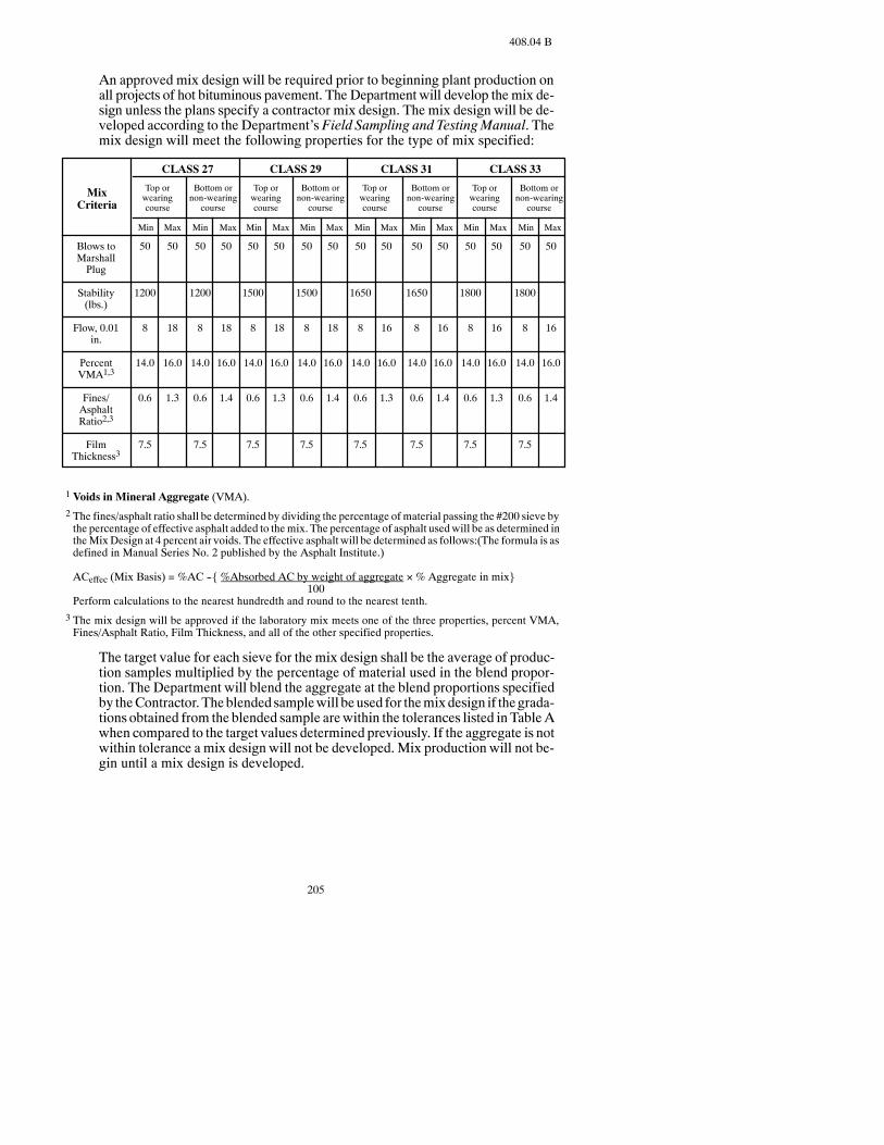
205
408.04 B
An approved mix design will be required prior to beginning plant production onall projects of hot bituminous pavement. The Department will develop the mix de-sign unless the plans specify a contractor mix design. The mix design will be de-veloped according to the Department’s Field Sampling and TestingManual. Themix design will meet the following properties for the type of mix specified:
Blows toMarshallPlug
Stability(lbs.)
Flow, 0.01in.
PercentVMA1,3
Fines/AsphaltRatio2,3
FilmThickness3
50
1200
8
14.0
0.6
7.5
MixCriteria
CLASS 27 CLASS 29 CLASS 31 CLASS 33
Top orwearingcourse
Bottom ornon-wearing
course
Top orwearingcourse
Bottom ornon-wearing
course
Top orwearingcourse
Bottom ornon-wearing
course
Top orwearingcourse
Bottom ornon-wearing
course
Min Max Min Max Min Max Min Max Min Max Min Max Min Max Min Max
50
18
16.0
1.3
50
1200
8
14.0
0.6
7.5
50
18
16.0
1.4
50
1500
8
14.0
0.6
7.5
50
18
16.0
1.3
50
1500
8
14.0
0.6
7.5
50
18
16.0
1.4
50
1650
8
14.0
0.6
7.5
50
16
16.0
1.3
50
1650
8
14.0
0.6
7.5
50
16
16.0
1.4
50
1800
8
14.0
0.6
7.5
50
16
16.0
1.3
50
1800
8
14.0
0.6
7.5
50
16
16.0
1.4
1 Voids in Mineral Aggregate (VMA).2 The fines/asphalt ratio shall be determined by dividing the percentage of material passing the #200 sieve bythe percentage of effective asphalt added to themix. The percentage of asphalt usedwill be as determined intheMixDesign at 4 percent air voids. The effective asphalt will be determined as follows:(The formula is asdefined in Manual Series No. 2 published by the Asphalt Institute.)
ACeffec (Mix Basis) = %AC --{ %Absorbed AC by weight of aggregate ×% Aggregate in mix}100
Perform calculations to the nearest hundredth and round to the nearest tenth.3 The mix design will be approved if the laboratory mix meets one of the three properties, percent VMA,Fines/Asphalt Ratio, Film Thickness, and all of the other specified properties.
The target value for each sieve for the mix design shall be the average of produc-tion samples multiplied by the percentage of material used in the blend propor-tion. The Department will blend the aggregate at the blend proportions specifiedby theContractor. Theblended samplewill beused for themixdesign if thegrada-tions obtained from the blended sample arewithin the tolerances listed in TableAwhen compared to the target values determined previously. If the aggregate is notwithin tolerance a mix design will not be developed. Mix production will not be-gin until a mix design is developed.
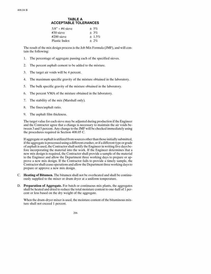
206
408.04 B
TABLE AACCEPTABLE TOLERANCES
5/8” -- #4 sieve 5%#30 sieve 3%#200 sieve 1.5%Plastic Index 2%
The result of themix design process is the JobMix Formula (JMF), and will con-tain the following:
1. The percentage of aggregate passing each of the specified sieves.
2. The percent asphalt cement to be added to the mixture.
3. The target air voids will be 4 percent.
4. The maximum specific gravity of the mixture obtained in the laboratory.
5. The bulk specific gravity of the mixture obtained in the laboratory.
6. The percent VMA of the mixture obtained in the laboratory.
7. The stability of the mix (Marshall only).
8. The fines/asphalt ratio.
9. The asphalt film thickness.
The target value for each sievemay be adjusted during production if the Engineerand the Contractor agree that a change is necessary to maintain the air voids be-tween 3 and 5 percent. Any change to the JMFwill be checked immediately usingthe procedures required in Section 408.05 C.
If aggregateor asphalt isutilized fromsourcesother than those initially submitted,if the aggregate isprocessedusingadifferent crusher, or if adifferent typeorgradeof asphalt is used, theContractor shall notify the Engineer inwriting five days be-fore incorporating the material into the work. If the Engineer determines that anewmix design is required, the Contractor shall provide a sample of the materialto the Engineer and allow the Department three working days to prepare or ap-prove a new mix design. If the Contractor fails to provide a timely sample, theContractor shall ceaseoperations andallow theDepartment threeworkingdays toprepare or approve a new mix design.
C. Heating of Bitumen. The bitumen shall not be overheated and shall be continu-ously supplied to the mixer or drum dryer at a uniform temperature.
D. Preparation of Aggregate. For batch or continuous mix plants, the aggregatesshall be heated and dried to reduce the total moisture content to one-half of 1 per-cent or less based on the dry weight of the aggregate.
When the drum-dryer mixer is used, the moisture content of the bituminousmix-ture shall not exceed 1 percent.

207
408.04 H
Aggregates prepared for usewith a cold-feed control shall be screened into twoormore fractions consisting of at least a fine and course aggregate stockpile. The ag-gregate shall be fed from the stockpile into separate compartments for accurateproportioning into the mixer.
E. Mixing.Allmaterials shall be introduced uniformly into the pugmill or the drumdryer, in the proportions necessary to produce the required quality. Bitumen shallbe proportionedwithin±0.24 percentage points of the percentage of bitumendes-ignated by the Engineer.
The requiredquantitiesof aggregate andbitumenshall be introduced into themix-er and thematerialsmixeduntil auniformandcompletecoatingof theaggregate isobtained.
F. MixTemperature.The temperature of the bituminousmixture at discharge fromthemixer shall not exceed300°F.The temperatureof themixat laydownshall be aminimum of 230°F. when the ambient temperature is above 60°F., and 250°F.when the ambient temperature is below 60°F.
If the density and temperature requirements of Section408.04.I are not beingmet,the actual mixing temperature shall be adjusted so the specified requirements aresatisfied.
G. Conditioning Existing Surface. When it becomes impractical to correct localirregularities on an existing surface with a single lift leveling course or the pave-ment course andmillingwasnot specified, the surface shall be brought to uniformcross section with additional bituminous mix. The mixture shall be thoroughlytamped or rolled and shall be the same mixture as specified for the next course.Where the existing surface is broken or unstable, the material shall be removed,disposed of, and replaced with the same mixture specified for the next course.
Spot leveling courses shall be blade laid in lifts not to exceed 3 inches in depth.
Patching operations include removal of existing surfacing, base, and subgradematerial to the depth required to obtain a stable subgrade. If required, a class ofaggregate satisfactory to the Engineer shall be placed and compacted to the bot-tom of existing bituminous pavement to a minimum depth of 3 inches below theexisting surface. The hot bituminousmaterial shall be placedwith amotor graderin lifts not to exceed 3 inches, compacted with rubber-tired equipment and curedfor 48 hours before being overlaid, except in such instances where the breakupoccurs during the actual pavingoperation. If thebreakupoccursduring thepavingoperation, a 48-hour curing period will not be required.
After removing loosedirt andother objectionablematerial fromthesurface, a tackcoat shall be applied to the surface and to the exposed edges of longitudinal andtransverse joints before placing a leveling or surface course.
H. Spreading and Finishing.All mixtures shall be spread and finished with bitumi-nous pavers to the required section leaving the mixture uniformly dense, smooth,and free from irregularities. In locations where it is impractical to use normal lay-down equipment, other methods may be used when approved by the Engineer.
Loadsofmixand sectionsof pavement containinguncoatedbatches of aggregate,segregated materials, aggregate which is obviously outside gradation Specifica-
208
408.04 H
tions, or too much bitumen will be rejected. Loads showing these characteristicsshall not be used in thework. If these conditions are evident after finishing opera-tions, the defective sections will be rejected, removed, and replaced at the Con-tractor’s expense. If the quality of themix on the road is in question, the Engineermay test samples taken from the in-place work prior to final acceptance.
The speedof thebituminouspaver shall be controlled to lay themixtureuniformlyand continuously without tearing or gouging. The paver’s speed shall not exceedthe manufacturer’s recommendation and shall be coordinated with the output ofthe plant to provide for a smooth, continuous operation with the paver.
All transverse and longitudinal joints, high or lowareas, and surface irregularitiesshall be leveled, filled, or raked before compaction. Loose material shall be re-moved from previously compacted lanes or joints before compacting adjacentlanes.
Pavingoperations shall be conducted tominimize the inconvenience to traffic andprotect existing and finished surfaces. Placing bituminousmixture shall progressso a single lane is not more than 1 day’s run in advance of any adjacent lane. Alter-ing the sequence of paving operations to best suit construction conditions may berequired.TheContractor shall not permit two-way traffic past themachine laydownoperation and 1-way traffic without the use of a Contractor-furnished pilot car.
A tack coat shall be applied on a previously placed layer or surface of pavementbefore spreading the next layer.
Hot bituminous pavement shall not be placed on bridge decks unless specified.
When required, the Contractor shall excavate locations where the new surfacingmeets existing pavement, bridge ends, or railroad crossings to allow full depthplacement of the surfacingcourse. If excavation is required, itwill be paid accord-ing to Section 104.03.
Rumble strips, when specified, shall be milled into asphalt shoulders and beplaced in a continuous pattern. Rumble strips will be discontinued across the fullwidth of all public and private (residential and commercial) road approaches, en-trance and exit ramps, and within designated city or urban limits. Rumble stripswill not be installed on shoulders less than 4 feet in width.
I. Compaction.
1. General.Except for shoulders, driveways, section line approaches, levelingcourses and patching, the bituminousmixture shall be compacted accordingto Section 408.04 I.3, Specified Density.
The sequence of rolling operations and the selection of type and number ofrollers shall be commensuratewith production and shall be adequate to attainthe specified density before the mat temperatures falls below 185°F. Thecompaction equipment for mainline paving shall include not less than oneSelf-Propelled Pneumatic-Tired Roller and one Smooth-Faced Steel-WheelRoller: Tandem -- TypeA,Smooth-FacedSteel-Wheel roller: Tandem -- TypeBorVibratoryRoller conforming toSections151.02B,C.2,C.3,C.4, orD.Acombination roller meeting the requirements of Section 151.02 E may be

209
408.04 I.2
used in lieu of the pneumatic-tired and vibratory roller. The Engineer has theoption to remove the pneumatic-tired roller if compaction can be achievedwithout the equipment.
Rolling shall begin at the edges and proceed parallel to the road centerlinewith each trip overlapping the previous roller pass, and progressing to thecrown of the road. When paving in echelon or abutting a previously placedlane, the longitudinal joint should be rolled first followed by the regular rol-ling procedure. On super-elevated curves, the rolling shall begin at the lowside andprogress to the high side byoverlappingof longitudinal tripsparallelto the centerline. Displacement resulting from reversing the direction of aroller, or fromother causes, shall be corrected immediatelywith rakes and theaddition of fresh mix. Care shall be exercised in rolling edges of the bitumi-nous mixture so line and grade of the edge is maintained.
In areas not accessible to rollers such as along forms, curbs, headers, andwalls,the mixture shall be thoroughly compacted with hand or mechanical tampers.
Anymixture that becomes loose and broken, mixedwith dirt, shows any ex-cessor deficiencyof bitumen, or is defective in anymanner, shall be removedand replacedwith fresh hotmixture, and compacted to the density of the sur-rounding area.
2. Ordinary Compaction. Ordinary Compaction shall be used on shoulders,driveways, section lineapproaches, bikepaths, levelingcoursesandpatchingprojects.
The testing, Contractor coring and compaction payment schedule specified inSection 408.05 Cwill not apply for leveling courses, patching, and bike paths.
When specified density on mainline is required, the laboratory testing re-quirements in Section 408.05 C.1 will apply for shoulders, driveways, andsection line approaches. The contractor coring and compaction paymentschedule in Section 408.05 C.2 and 408.05 C.3 will not apply.
Compaction consists of initial or breakdown rolling, intermediate rolling,and final or finish rolling.
Breakdown rolling shall consist of one or more complete coverages with arollermeeting the requirementsof Sections151.02B, 151.02C.2, or 151.02D.
Breakdown rolling shall be followed by intermediate rolling with a rollerconforming to Section 151.02 B until the surface is tightly bound and showsno displacement under the roller. Intermediate rolling shall be completed be-fore the mat temperature falls below 185°F. The Engineer has the option toremove the pneumatic-tired roller if compaction can be achieved without,and there is a problemwith the tirespickinguporwith rollermarks in themat.
The final rolling shall be performed with a roller conforming to Section151.02 C.3 or 151.02 D in the static mode, and shall continue until rollermarks are eliminated.
The Contractor may be required to modify the rolling sequence to best suitconstruction conditions.

210
408.04 I.2
When compacting leveling courses and patches spread with motor gradersthe initial rolling shall be by pneumatic-tired rollers done simultaneouslywith the spreading.Additional pneumatic-tired rollers required for obtainingcompaction shall conform to Section 151.02 B. The roller specified for finalrolling may be omitted with approval of the Engineer. The desired degree ofcompaction will be considered obtained when the surface is tightly boundand shows no displacement under operation of the roller.
3. Specified Density. This method provides for compacting bituminous mix-ture on interstate crossroads, ramps, rest area approaches, parking lots, andmainline pavement according to the density requirements specified in Sec-tion 408.05 C.
Bituminous mixture placed on shoulders, driveways, and section line ap-proaches are exempt from the specified density requirements. Suchmixturesshall be compacted to the satisfaction of the Engineer with the same rollersand rolling sequences used on the mainline. In confined areas, other rollersmay be used, as approved by the Engineer.
J. Joints. Joints shall be tacked and constructedwith adequate bondon abutting sur-faces. Vertical construction joints in successive courses shall be placed so thejoints do not fall in the same vertical plane.
Pavement placed against the surface of curbing, gutters, manholes, and similarstructures shall be placed uniformly high near the contact surfaces so the pave-ment is slightly higher than the edge of the structure after compaction.
K. Maintaining Completed Course.Upon completion of the final rolling and fin-ishing, surfacemaintenance requireddue to constructionoperations shall be at theContractor’s expense until the next or final surface is placed or until the work hasbeen accepted by the Department. Maintenance shall include the removing, re-placing, reshaping, and recompacting of damaged areas.
L. Tolerances.The surface shall be smooth, uniform, and true to Plan crown, align-ment, and grade. Surfacing thicknesses shown on the typical sections areminimumand the estimated plan tonnages shall be used uniformly throughout the Project.
Any low or high defective areas shall be corrected as directed by the Engineer.Corrective work shall include patching or cutting out the surface and replacingwith fresh hot bituminous mixture, or by milling the surface. The surface of thefinished pavement shall be free from irregularities exceeding 3/16 inch as mea-sured with a 16-foot straightedge parallel and perpendicular to the centerline ofthe roadway.
Deficiencies insmoothness, improperlyconstructed joints, andsurface irregulari-ties shall be correctedwith a seconddiagonal rolling crossing the line of the first atthe Contractor’s expense.
M. Limitations.
1. Weather.Hotbituminousmix shall not beplacedonadampsurface, ona fro-zen roadbed, or whenweather conditions prevent the proper handling or fin-ishingof thebituminousmixtures. Presenceof frostparticles in the roadbed is

211
408.05 A.1
sufficient evidence of being frozen. Hot bituminous mix shall not be placedwhen the air ormat surface temperatures are below the followingminimums:
AIR TEMPERATURE
SubsurfaceCompacted Air Temperature Course and Existing MatThickness Surface Course Approaches Temperature*
1-1/2” or 45°F. 40°F. 40°F.less
More than 40°F. 35°F. 40°F.1-1/2”
*Existingmat temperature will bemeasuredwith an infrared sensing thermometer or by a conventionalthermometer inserted into a 1-inch deep hole in the pavement and filled with water, oil, or grease.
2. Operational.Traffic shall not be permitted on the completed surfacing untilthe lift has been compacted and has cooled sufficiently to prevent damage.
N. Bituminous Pavement Sloughs. Bituminous pavement sloughs shall be com-pactedwith rollers capable of providing a smooth finished compacted slough thatis free of tire marks and unevenness or drop-off. Density tests are not required.
O. Superpave.All criteria for shall followSection408.Testingmethods shall followthe procedures of the Department’s Field Sampling and Testing Manual.
408.05 ACCEPTANCE.
The aggregate gradation pay factor in Section 408.05A.1. and the bitumen uniformityrequirements in Section 408.05 B.2 will not apply when the total plan quantity of hotbituminouspavement is4,000 tonor less.When the totalPlanquantityof hotbituminouspavement is 4,000 ton or less thematerial will be accepted according to Section 105.07.
A. Aggregate.
1. Gradation. Aggregate will be sampled and tested in lot sizes equal to thenumber of tons produced.One aggregate samplewill be tested for each1,500ton ofmix producedwith aminimumof one sample per day. Payment for themix represented by the samples will be based on the uniformity of the testresults.
The Contractor shall obtain all aggregate samples at random times deter-mined by and under the observation of the Engineer. The samples shall betaken from the cold feed belt according to AASHTO T 2, Section 4.3.1 or4.3.2. The sample shall be split into two representative samples, numbered andbagged by the Contractor under the observation of the Engineer. Both halves ofthe sample shall be submitted to the Engineer. The untested half of the samplewill be retained by the Engineer for 24 hours after the test results are madeknown to the Contractor. Either party may request that the second half of thesample be testedwithin this 24-hour time frame. The test results from this re-test shall replace the test values of the initial test.
If any two tests in a lot result in the variance of any one or more sieves fromthe JMFgradation target value bymore than the tolerances listed below, a de-

212
408.05 A.1
duction on the entire lot will be applied. A deduction will be calculated foreach sieve out of the acceptable range. The total deductionwill be the sumofthe deductions calculated for each sieve out of the acceptable range. The PayFactor for the aggregate material will be adjusted according to the followingformula:
Pay Factor = 100 -- Deviation from the Target Range*100
Lot Pay Factor = 100 -- ∑ (Deduction)
*Target Range = target value + or -- the acceptable tolerance value listed below:
AGGREGATE TOLERANCES
5/8 sieve1 + 2%1/2” -- #8 sieve2 ± 7%#16 -- #50 sieve2 ± 6%#200 sieve2 ± 2%
1Providing all material passes the 3/4-inch sieve.
2The target value + or -- the tolerance allowed shall not exceed the specified gradation range.
The deduction will be waived by the Engineer if; the daily air voids of themarshall plugs as determined in Section 408.05 C.1 are between 3 and 5 per-cent and the aggregate gradation for each sieve is not outside the gradationband for the class of aggregate specified. If both of these conditions are met,the Lot Pay Factor will be 1.00.
If the material fails to meet the specifications for two consecutive lots, theContractor shall not incorporate any additional material into the work untiltheEngineer is satisfied that theContractor is taking necessary corrective ac-tion tomeet the Specifications. The Engineermay request that a newmix de-sign be developed if the Contractor is unable to meet the Specifications.
2. AdditionalAggregateTests.Aggregate samples todetermine shale content,plasticity index, fractured faces, and L. A. Abrasion loss will be taken by theContractor, under theobservationof theEngineer, before theadditionofbitu-men to the mix.
The shale content and plasticity index of the aggregatewill be determined bythe average of test results from three random samples taken from the coldfeed belt fromeach lot of 10,000 tons or fraction thereof. The sampleswill betested and the material will be accepted if the average of the three samplesmeets the specified requirements. If each of the samples is within the speci-fied limits, only one of the three sampleswill be tested from each subsequentlot. If at any time the sample tested does notmeet the specified requirements,the remaining two sampleswill be tested. The average of these three sampleswill then be used to determine acceptance of thematerial. The testing of threesamples per lot will continue until all three samples are within the specifiedlimits, then only one of the three sampleswill be tested fromeach subsequentlot. If the average exceeds the specified maximum for shale content, the unitprice for the bituminousmixturewill be adjusted according to Section 408.07B.

213
408.05 B.2
If the average fails tomeet the specified requirements for plasticity, themate-rial will be rejected, unless the Engineer elects to accept it under Section105.07.
The L. A. Abrasion loss percentage of aggregate will be determined on thebasis of 1 composite aggregate sample taken and tested during the beginningof the aggregate stockpiling. If this percentage exceeds themaximumallow-able loss, the material will not be accepted.
The percentage of fractured faces for course aggregates will be determinedby the average of test results from three random samples taken from the coldfeed belt for each lot of 10,000 tons of bituminous mixture produced. Thesamples will be tested and the material will be accepted if the average of thethree samples meets the specified requirements. If each of the samples iswithin the specified limits, only one of the three samples will be tested fromeach subsequent lot. If at any time the sample tested does not meet the speci-fied requirements, the remaining two samples will be tested. The average ofthese three sampleswill thenbeused todetermine acceptance of thematerial.The testing of three samples per lot will continue until all three samples arewithin the specified limits, then only one of the three samples will be testedfrom each subsequent lot. If the average fails to meet the specified require-ments, thematerial will be rejected unless the Engineer elects to accept it un-der Section 105.07.
B. BitumenContent.The requiredbitumencontent, or target percentage,will bedes-ignated by the Engineer.
The quantity of bitumen used and paid for fromeach lotwill be determined by theuseofdailyoil cutoffs following theproceduresoutlinedon theMixBitumenCut-off Report. A lot shall be defined as the amount of bitumen used each productionday.
The pay factor for the hot bituminous pavement, adjusted for bitumen content,will be the lowest pay factor determined by both of the following methods:
1. Average. If the daily cutoff, as determined on the Mix Bitumen Cutoff Re-port, deviates from the target percentage set by the Engineer by more than0.24 percentage points the pay factor will be determined from the followingtable:
BITUMEN CONTENT
Pay Deviation from TargetFactor in Percentage Points
1.00 0.00--0.240.98 0.25--0.290.95 0.30--0.340.92 0.35--0.39* 0.40 & Over
*The Engineer will determine the pay factor according to Section 105.07.
2. Uniformity.TheEngineerwill check the asphalt content each time an aggre-gate sample is taken. The checkswill be based on readings from the totalizers
214
408.05 B.2
for the aggregate and the bitumen as outlined in the Asphalt Content Deter-minationReport. If the asphalt content from any random reading varies fromthedaily averageof the readingsbymore than0.24percentagepoints, thepayfactor for the hot bituminous material will be adjusted according to the fol-lowing formula:
Pay Factor = 100 - [ 20 (* Deviation - 0.24) ]100
*Deviation from the average daily asphalt content.
C. Compaction.
1. Testing. The compaction of themixture will be accepted in lot sizes equal tothe number of tons placed each production day. The density of the pavementwill bedetermined fromcoresobtainedby theContractor, as specified inSec-tion 408.05 C.2.
Each sublotwill beonepaverwidthwide, excluding the shoulders, 2,000 feetlong, and of the depth specified for the pavement course. If the partial sublotremaining at the end of a production day is 1,000 feet in length or longer, itwill be considered a separate sublot. If it is less than 1,000 feet long, it will beincluded in the last complete sublot. If the total day’s production is less than2,000 feet long (one paver width wide), that productionwill be considered a lot.
Themean density of themainline pavement placed each production daywillbe the averageof thedensitiesof all of that day’s sublots. In addition to testingrandomly selected locations, theEngineer reserves the right to direct the test-ing of any areas which appear defective. Defective areas will be rejected un-less the Engineer elects to accept it under Section 105.07.
The Contractor, under the observation of the Engineer, shall:
a. Obtainmix samples frombehind the paver at random times specified bytheEngineer.One sample shall be takeneach timeanaggregate sample istaken; and
b. Compact 3marshall specimenswith each sample taken to determine thefield marshall density. The number of blows applied to the marshallspecimens shall be 50, unless otherwise specified, and the temperatureof the mix shall be 270 plus or minus 5°F.; and
c. Determine the Maximum Theoretical Density of each sample taken.
Themethodsused toobtain the samples, compact themarshall specimensanddetermine the Maximum Theoretical Density shall be as outlined in the De-partment’s Field Sampling and Testing Manual.
For a project on an NHS route, the Engineer will do acceptance testing ac-cording to Appendix G of the Department’s Field Sampling and TestingManual.
2. Contractor Coring. The Contractor shall take two cores in each sublot at arandomlocationdeterminedby theEngineer andunder theobservationof the
215
408.05 C.3
Engineer.After coringandsawing, the cores shall behandedover to theEngi-neer. The cores shall be taken adjacent to each other and the average of thetwo cores shall be used for determining the density of the sublot.
The Contractor shall take one additional full-depth core per mile, under theobservation of the Engineer, with one location in each lane, for the DistrictMaterials Coordinator to use as an independent assurance test. The DistrictMaterials Coordinator will determine the locations of these cores. The coresshall not be sawed by the Contractor.
The coring machine shall cut a cylindrical sample in the compacted asphaltlift without disturbing the density of the sample. The core samples shall be 4to 6 inches in diameter. Themasonry sawshall cut the core sample soonly thecompacted layer to be tested is removed; and the core is in a condition suit-able for testing.
Coringof eachday’spaving shall be completedno later than thenextworkingday following the placement of the lift. Cores shall be taken through the fulldepthof the in-place asphalt pavement.The surfaceof theoutsideof thecoresshall be smoothwith no distortion of the cylindrical shape or displacement ofthe aggregate particles. A masonry saw shall be used to remove the com-pacted layer from the full-depth core without damaging the newly placed as-phalt material.
The Contractor shall fill all holes remaining in the surface of the roadwaywith bituminous material and compact the material as directed by the Engi-neer. Each core shall be numbered or lettered to identify the location fromwhich the corewas taken. Themarking system shallmeet the approval of theEngineer.
TheContractormayelect to take a check sample, at theContractor’s expense,whenever the average density of a set of cores is 89 percent or less than theTheoretical MaximumDensity. A check sample shall be a set of cores takenwithin 2 feet of the location of the failing set of cores. The average density ofthe check sample cores will be the result used to determine the Unit Price ofthe hot bituminous pavement.
Retests and additional tests will not be taken or paid for unless approved by,or directed by, the Engineer.
TheContractor shall control traffic according to the traffic control plan to en-sure the safety of the coring crew and the traveling public. TheEngineermayalter these requirements depending on the location of the coring operation inrespect to the existing traffic control zone, and in situations where traffic isbeing controlled by a pilot car and/or flaggers. Coring operations shall nottake place adjacent to the paver to avoid blocking traffic.
3. Compaction Payment Schedule.
Acceptance of mainline pavement placed on any production day will bebased on the average density of the pavement compared to the daily averagemaximum theoretical density (MTD) determined for each lot of pavementplaced.The average density of the field cores shall be at least 91percent of the

216
408.05 C.3
daily averageMTD. Each individual sublot shall have an average density of atleast 89 percent of the daily average MTD. If the average density of the fieldcores is less than 91percent of the daily averageMTDor any sublot is less than89percent of thedaily averageMTDtheUnit Priceof thehot bituminouspave-ment will be adjusted according to the following tables:
PAVEMENT DENSITYADJUSTMENT OF UNIT BID PRICE PER LOT
Pay Average PavementFactor A Density1.00 91% or greater0.99 90.0% -- 90.9%0.975 89.0% -- 89.9%0.95 88.0% -- 88.9%0.925 87.0% -- 87.9%* Less than 87.0%
Pay Lowest Density ofFactor B any Sublot1.00 89% or greater0.99 88.0% -- 88.9%0.98 87.0% -- 87.9%0.97 86.0% -- 86.9%0.96 85.0% -- 85.9%* Less than 85.0%
*The Engineer will determine whether the material may remain in place. The Pay Factor for thematerial allowed to remain in place shall be .70 for Pay Factor A and .80 for Pay Factor B.
The density of the field coreswill be determined according to the proce-dures of the Department’sField Sampling and TestingManual. The To-tal Pay Factor will be the product of the pay factor for the average pave-ment density and the lowest sublot.
TOTAL PAY FACTOR = (PAY FACTOR A) × (PAY FACTOR B)
408.06 METHOD OF MEASUREMENT.
The estimated quantities provided may be adjusted by the Engineer in the field. Anyincrease or decrease in the quantities used shall not be a basis for renegotiation in theprice bid for these items.
A. Hot Bituminous Pavement.Hot Bituminous Pavement will be measured by theTon or SquareYard according to Section 109. Batchweightswill not be permittedas amethodofmeasurement unless the plant is equippedwith an automatic batch-ing and weighing system with an automatic printer system which prints theweights of each batch and issues aweigh ticket for each load. TheTonnagewill bethe weight used in the accepted pavement and no deduction will be made for theweight of bitumen used in the mixture.
B. Bitumen.Bitumenwill bemeasured according to Section 109 and the quantity ofbitumen will be the number of Tons or Gallons used in the accepted work.
217
408.07 B
C. Cored Sample. Each individual cored sample that is removed in the requiredconditionwill bemeasured as a unit. Thework vehicle, coringmachine,masonrysaw, and the shadow vehicle will not be measured for payment, but will be in-cluded in the measurement of the cored sample.
D. Rumble Strips.When a bid item is included in the Plans, the quantity for rumblestrips isdeterminedbyproject length for each shoulderpermile.Thequantitypaidfor will be the quantity shown in the Contract, provided the project is constructedas shown in the Plans. A deduction in length will not be made for discontinuedrumble strips across road approaches, ramps, etc. as identified in the notes in thestandard drawings.
When the bid item for rumble strips is each, payment will be for all rumble stripsinstalled at a stop intersection in one lane.
408.07 BASIS OF PAYMENT.
Payment will be made at the Contract Unit Price for the following:
Pay Item Pay Unit__Hot Bituminous Pavement Ton__Asphalt Cement Ton or GallonSuperpave, FAA 40 TonSuperpave, FAA 41 TonSuperpave, FAA 42 TonSuperpave, FAA 43 TonSuperpave, FAA 44 TonSuperpave, FAA 45 TonCored Sample EachRumble Strips Each or Mile
This payment will be full compensation for all labor, equipment, andmaterials neces-sary to complete the work.
When price adjustments are required for failingmaterial or patching, payment will bemade as follows:
A. Determination of the payment adjustment of a lot of bituminous mixture will bemade by successivelymultiplying the Contract Unit Price per Ton of the bid itemby the applicable pay factors as determined in Sections 408.05 A, 408.05 B, and408.05 C.
B. When the averageof the test results specified inSection408.05A.2 showsa largershale content than the maximum allowable specified, the following deductionfrom the Bid Price for the bituminous mixture item will be made:
One percent reduction in unit price for each 0.2 percent above the maximum al-lowable percentage. If the percentage of shale exceeds the allowable limits by 2percentormore, thematerialwill be rejectedunless theEngineer elects to accept itunder Section 105.07.
This reductionwill apply to lots of 10,000 tons, andwill be applied independentlyof Section 408.05 A.1.

218
408.07 C
C. Material for patching or leveling of an existing bituminous surface constructedunder apreviousContract shall beobtained from the tonnageprovided in thebasisof estimate and will be paid according to the following provisions:
1. For all levelingandpatchingwhennoexcavation is required, paymentwill bemade at the Contract Unit Prices for the materials used in the repair.
2. When the patching requires excavation, themethod and site of disposal of thewaste materials shall be subject to the approval of the Engineer, and:
a. If the excavatedmaterial is disposed ofwithin theRight ofWay adjacentto the work site, payment for the bituminous mixture used in the repairwill be made per Ton as follows: Contract Unit Price plus the price perTon listed in the “Price Schedule PS-l.”
b. If the excavatedmaterial is loaded andhauled to a disposal area not adja-cent to thework site, payment for the bituminousmixture used in the re-pair will be made per Ton as follows: Contract Unit Price plus the priceper Ton listed in the “Price Schedule PS-l.”
c. If aggregate is required to replace excavatedmaterial in the existingbaseor subgrade, payment for the class of aggregate usedwill bemade underSection 104.03. Payment will include disposal of excavated material,and the furnishing, placing, and compacting of the aggregate.
d. Payment for prime, tack, and the bitumen in the mix used in the repairwill be made at the Contract Unit Prices for those items.
SECTION 409HOT BITUMINOUS PAVEMENT
QUALITY CONTROL/QUALITY ASSURANCE
409.01 DESCRIPTION.
This work shall consist of constructing one or more courses of bituminous pavementon a prepared surface for Quality Control/Quality Assurance (QC/QA) projects. TheContractor shall be responsible for process control, and shall perform the necessarytesting to control the quality of the work. When specified on the plans the contractorshall develop a mix design.
409.02 MATERIALS.
A. Bitumen. The bitumen shall meet Section 818 and will be of the type and gradespecified in the Contract. Bitumen will be accepted as outlined in the CombinedState BinderGroup agreement forNorthDakota. Sampleswill be obtained by the

219
409.04
Contractor under the observation of the Engineer, and immediately handed overto the Engineer for shipping and testing.
B. Aggregate. The Aggregate Gradation Master Range for the class of aggregatespecified shall conform to the following requirements:
Sieve Size Percent Passing5/8 in.* 1001/2 in. 90 -- 100No. 4 45 -- 80No. 30 10 -- 35No. 200 2.0 -- 7.0
*A tolerance of 2 percent in the amount passing the 5/8-inch sieve will be permitted providing allmaterial passes the 3/4-inch sieve.
The gradation values listed are the extreme limits for design purposes. DuringProductionmixture tolerance on all sieves, may fall outside the aggregate masterrange, except on the 200 sieve. The remaining physical properties, (lightweightpieces, P.I., fractured faces, etc.) for the class of aggregate specified, shall be asspecified in Section 816.03 of the Standard Specifications.
409.03 EQUIPMENT.
Equipment shall be as specified in Section 408.03.
409.04 CONSTRUCTION REQUIREMENTS.
Contractor Quality Control. Quality Control (QC) will be the responsibility of theContractor. TheContractorwill performquality control sampling, testing, and inspec-tionduring all phases of theworkat a rate sufficient to assure that thework conforms tothe Contract requirements. The Contractor shall have at least one person on the Proj-ect, at all times,who is certified as aAsphaltMixController andoneperson certified asan aggregate lab and asphalt mix tester. The inspector shall be certified as an AsphaltPavement Inspector.Certification requirementswill beasoutlined in theDepartment’sTransportation Certification Program (TCP).
QualityControl Plan. Prior to beginningwork theContractor will submit a “QualityControl Plan” to theEngineer. ThePlanwill contain: 1) the names andphonenumbersof the individual(s) responsible for the Contractor’s quality control program; 2) a list-ing of the technician(s) responsible for the quality control testing; 3) an organizationalchart indicating lines of authority (including names and phone numbers); 4) a summaryof the qualifications of theQuality Control Technicians; and 5) details of the Contrac-tor’s quality control plan addressing but not limited to the following items: 1) pit op-erations andmethods used to control uniformity, reducing segregation, and efficientlyutilizing the aggregate resources of the pit; 2) plant operations discussing proposedequipment (number of bins, plant type, etc.) and method of operations; 3) testing fre-quency andhow thismeets the intent of theSpecification; and4) discussionof how theContractor’s quality control programwill respond to the need for corrective action asdefined in Section 409.04 O.2.
TheDepartmentwill provide theContractorwith: 1) the names and phone numbers ofthe individual(s) responsible forproject administration;2) a listingof the technician(s)

220
409.04
responsible for the quality assurance testing; and 3) an organizational chart indicatinglines of authority (including names and phone numbers).
QualityControlLaboratory.TheContractorwill furnish andmaintain aTypeC lab-oratory at theplant as specified inSection706of theStandardSpecifications.Anyoth-er laboratory location must be approved by the Engineer. The laboratory will be fur-nished with the necessary equipment and supplies for performing the Contractor mixdesign if called for on theplans and for the contractorQC testing.Duringproductionoftheaggregate, theContractormayfurnisha labequippedwith thenecessaryequipmentto perform the following aggregate tests: bulk and apparent specific gravity, gradationanalysis, lightweight pieces of aggregate, plastic index, and fractured faces. The TypeC laboratory must be set up and ready to use before the paving operation begins. Thislaboratory will be measured and paid according to Section 706.02 C.
The Contractor will provide an aggregate lab and asphalt mix tester, as outlined in theDepartment’sTCP, to performall testing including all testingperformedduringaggre-gate production. The Contractor shall also provide testing equipment that meets therequirements for all tests called for by Specifications.
Engineer’sLaboratory.TheContractorwill provide an additional TypeC laboratoryto be used during actualmix productionby theDepartment’s aggregate lab and asphaltmix tester. The testing equipment will be provided by the Department. The lab will beset up at the plant prior to production of the bituminous mix and be made available totheEngineer forQualityAssurance testing.TheContractor and theEngineerwill sharethe Triple Hammer provided for the Contractor’s lab.
A. Pit Operations and Stockpiling of Aggregate.During production of the aggre-gate, the aggregate will be tested for gradation, plastic index, fractured faces, andlightweight pieces of aggregate. The testing frequency for gradation will be onetest per 1,000 tons of material produced for each aggregate stockpile. The testingfrequency for the plastic index, fractured faces, and lightweight pieces of aggre-gate will be the average of three random composite samples from the first 5,000tons of material produced. If all three samples pass, the testing frequency willchange tooneof three samples tested for each10,000 tonsofmaterial produced. Ifa sample fails, the remaining two samples will be tested and averaged for accep-tance of that lot. The testing frequencywill then revert to the average of three testsper 5,000 tons until all three samples pass, then one of three sampleswill be testedfor each 10,000 tons.
After 10,000 tons ofmaterial is produced, theContractorwill provide theDepart-ment with an aggregate sample representing each stockpile and asphalt requiredfor the mix design. The Contractor shall develop a preliminary mix design andsubmit the results to the Department. This mix design is for informational pur-poses to assure the Contractor has produced specified material. The Contractorshall provide all of the information required for the JMF, except the stability of themix. Themix designwill be developed according to theDepartment’sField Sam-pling and Testing Manual and will meet the requirements specified in Section409.04 B.
The Contractor will sample and test the aggregate according to the Department’sField Sampling and Testing Manual.
The Contractor shall provide the Engineer with copies of the test results for eachstockpile of aggregate that will be incorporated into the mix within 48 hours of
221
409.04 B
samplecollection.The test reportswill include results for gradation, plastic index,fractured faces, lightweightpiecesof aggregate and thebulkandapparent specificgravity.
During the firstweekof aggregate production, for eachclass of aggregate, as soonas the Contractor determines the aggregate is representative, and prior to the ini-tial mix design, the Contractor shall obtain a 90-pound sample of each aggregatecomponent. The Contractor shall split the samples under the observation of theEngineer.One-half of eachaggregate samplewill be submitted to theEngineer fortesting. The Contractor and the Engineer will test the samples to determine thebulk (dry) and apparent specific gravity and the percent water absorption by dryweight of aggregate.The testingwill be completed according toAASHTOT84,T85 and the procedures in the Department’s Field Sampling and Testing Manual.One test will be performed for each 10,000 ton of each aggregate component pro-duced. A minimum of two tests will be required for each aggregate component.Testing shall commencewithin twoworkingdaysof sampling.Test resultswill bereported to each party as soon as they are available.
If the individual specific gravity values determined by the Contractor and theDe-partment correlate within 0.040, the average of the Contractor’s numbers will beused to calculate the absorption, fines to asphalt ratio, and voids inmineral aggre-gate (VMA). If the individual specific gravity values determined by the Contrac-tor and Department do not correlate within the allowable tolerance (0.040), or iftheContractor fails to supply an aggregate thatmeets themix design criteria then:
1. The mix design will not be approved and mix production will not begin.
2. The Contractor has the option of running the test together with Departmentpersonnel at the District Lab and use those results, or testing differences canbe resolved according to the procedures in the Department’sField Samplingand Testing Manual.
If theDepartment’smixdesignmeets the properties specified and theDepartmentand the Contractor mutually agree it is necessary to adjust the aggregate produc-tion operation to produce an aggregate that will improve the mix design proper-ties, theDepartmentwill negotiate an equitable adjustmentwith theContractor toproduce an aggregate that meets the desired mix design properties.
B. Mix Design. The mix design used will be a lab mix design developed by the De-partment or determined by the Contractor and approved by the Department. Themix design will be developed according to the Department’s Mix Design Proce-dure.Themixdesignwill bedevelopedusing the type, grade andsourceof asphaltthat will be used on the project. The target value for each sieve for themix designshall be the averageof production samplesmultipliedby thepercentageofmateri-al used in the blend proportion. The blended sample will be used for the mix de-sign if the gradations obtained from the blended sample are within the toleranceslisted inTableCwhencompared to the target values. Themix designwillmeet thefollowing properties for the type of mix specified:

222
409.04 B
Blows toMarshallPlug
Stability(lbs.)1
Flow, 0.01in.
PercentVMA2
Fines/AsphaltRatio3
50
1200
8
14.0
0.6
MixCriteria
CLASS 27 CLASS 29 CLASS 31 CLASS 33
Top orwearingcourse
Bottom ornon-wearing
course
Top orwearingcourse
Bottom ornon-wearing
course
Top orwearingcourse
Bottom ornon-wearing
course
Top orwearingcourse
Bottom ornon-wearing
course
Min Max Min Max Min Max Min Max Min Max Min Max Min Max Min Max
50
18
16.0
1.3
50
1200
8
14.0
0.6
50
18
16.0
1.4
50
1500
8
14.0
0.6
50
18
16.0
1.3
50
1500
8
14.0
0.6
50
18
16.0
1.4
50
1650
8
14.0
0.6
50
16
16.0
1.3
50
1650
8
14.0
0.6
50
16
16.0
1.4
50
1800
8
14.0
0.6
50
16
16.0
1.3
50
1800
8
14.0
0.6
50
16
16.0
1.4
1Desired minimum value, the Engineer will evaluate the actual value determined in the mix design.
2Voids in Mineral Aggregate (VMA).
3Required Range, the fines/asphalt ratio shall be determined by dividing the percentage of material passingthe #200 sieve by the percentage of effective asphalt added to themix. The percentage of asphalt usedwill beas determined in the Mix Design at 4 percent air voids. The effective asphalt will be determined as fol-lows:(The formula is as defined in Manual Series No. 2 published by the Asphalt Institute.)
ACeffec (Mix Basis) = %AC --{ %Absorbed AC by weight of aggregate ×%Aggregate in mix}100
Perform calculations to the nearest hundredth and round to the nearest tenth.
1. The Department’s Developed Mix Design.
The Contractor will provide the Engineer with an aggregate sample repre-senting each stockpile as specified previously. A sample tag identifying theproject number, pit location, and class of aggregate shall be attached to thesample. The total weight of the combined sample will be approximately 150pounds and meet the gradation of the class of aggregate specified.
TheContractorwill alsoprovideeight1-quart cansofbitumenof the typeandgrade specified in the Plans. The bitumen will meet all requirements of Sec-tion 818 and will be from the supplier the Contractor uses for the project.
The Contractor will submit the aggregate sample, the blend proportions, theaverage production sample results, and the type, grade, AC specific gravity,and name of the supplier of the bitumen inwritingwith the submission of thesamples. The aggregate and bitumen samples will be submitted a minimumof seven working days before the start of the planned paving operations.
If aggregate or asphalt is utilized from sources other than those initially sub-mitted, the aggregate is processed using a different crusher, or if a differenttype or grade of asphalt is used, the Contractor shall notify the Engineer inwriting five days before incorporating the material into the work. If the Engi-neer determines that a new mix design is required, the Contractor shall pro-
223
409.04 B.2.b
vide a sample of the material to the Engineer and allow the Department 3working days to prepare a newmix design. If theContractor fails to provide atimely sample, the Contractor shall cease operations and allow the Depart-ment three working days to prepare a new mix design.
The target value for each sieve for themix design shall be the average of pro-duction samples multiplied by the percentage of material used in the blendproportion.TheDepartmentwill blend theaggregate at theblendproportionsspecifiedby the contractor. Theblended samplewill be used for themixdesignif the gradations obtained from the blended sample are within the toleranceslisted in Table Awhen compared to the target values determined previously. Ifthe aggregate is not within tolerance a mix design will not be developed.
2. Contractor Developed Mix Design.
After the Contractor has sufficient material produced to assure uniform pro-duction of each aggregate component, a mix design or series of mix designsshall be performed until a mix design is developed meeting all the require-ments specified. The Contractor shall submit the completed mix design in-cluding all test data to the appropriate District Materials Laboratory.
The final mix design report shall be submitted using a Department-approved computer format. The Contractor shall also submit sufficientamount of individual aggregate components and asphalt. The aggregate andasphalt will have the same properties as was used for the Contractor’s mixdesign.
The Contractor’s mix design will be reviewed within five working days.
If the Department’s verification confirms the results of the Contractors mixdesign arewithin the tolerances specified in TableC, theContractorsmix de-signwill be approved.The tolerance forMaximumSpecificGravity shall notbe determined in Table C, but shall be ± 0.30 percent. If the Contractor’smixdesign is not approved, the Contractor shall submit another mix design. Anapproved mix design will be required prior to beginning production of hotbituminous pavement.
If aggregate or asphalt is utilized from sources other than those initially sub-mitted, the aggregate is processed using a different crusher, or if a differenttype or grade of asphalt is used, the Contractor shall notify the Engineer inwriting five daysbefore incorporating thematerial into thework. If theEngi-neer determines that a newmix design is required, theContractor will devel-op another mix design and submit it for approval with the same informationas required for the initial mix design, before incorporating this material intothemixture If theContractor fails to submit an approvedmixdesign andpro-vide timely samples, the Contractor will cease operations until an approvedmix design is developed.
The result of the mix design process is the JobMix Formula (JMF), and willcontain the following:
a. The percentage of aggregate passing each of the specified sieves.
b. The percent asphalt cement to be added to the mixture.

224
409.04 B.2.c
c. The target air voids will be 4 percent.
d. Themaximumspecific gravity of themixture obtained in the laboratory.
e. The bulk specific gravity of the mixture obtained in the laboratory.
f. The percent VMA of the mixture obtained in the laboratory.
g. The stability of the mix.
h. The fines/asphalt ratio.
i. The asphalt film thickness.
Determination of Surface Area
Sieve Analysis Percent Passing
Sieve Max. Size No. 4 No. 8 No. 16 No. 30 No. 50 No. 100 No. 200
CombinedGrading *** *** *** *** *** *** *** ***
Coefficient 0.02 0.02 0.04 0.08 0.14 0.30 0.60 1.60
**** Film Thickness FT = (Pbe)(4885)(100)(SA)
Where: Pb = asphalt cement, percent, mixture basisPba = percent AC absorbed by weight of aggregatePs = aggregate, percent mixture basisPbe = effective asphalt content, percent, mixture basisFT = film thickness (Microns)SA = surface area (ft2/lb)
**The Dust/Effective asphalt ratio shall be determined by dividing the percentage of material passing the#200 sieve by the percentage of effective asphalt added to the mix. The percentage of asphalt used willbe as determined in the Mix Design at 4 percent air voids.
The effective asphalt will be determined as follows: (The formula is as defined in Manual Series No. 2published by the Asphalt Institute.)
Pbe = Pb -- (Pba)(Ps)100
***The gradation used for calculating film thickness and dust/effective A.C. ratio will be the combinedgradation results of the actual material used to run the mix design. Perform calculations to the nearesthundredth and round to the nearest tenth.
(Sections C through N are specified in the respective sections of 408.04)
O. Quality Control Sampling and Testing. During production of the bituminousmix, the Contractor will be required to perform random sampling and testing onthe aggregate and bituminousmix as themix is being produced and placed on theroadway. All test results will be provided to the Engineer by noon the followingday.
TheContractorwill sample and test the bituminousmix as outlined in theDepart-ment’s Field Sampling and Testing Manual.
TheContractorwill sample theaggregate fromthecold feedand test the aggregateusing the Department’s sampling and testing procedures. The sieve analysis will
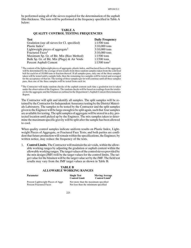
225
409.04 O.1
be performed using all of the sieves required for the determination of the asphaltfilm thickness. The tests will be performed at the frequency specified in Table Abelow:
TABLE AQUALITY CONTROL TESTING FREQUENCIES
Test Daily FrequencyGradation (use all sieves for Cl. specified) 1/1500 tonsPlastic Index1 3/10,000 tonsLightweight pieces of aggregate1 3/10,000 tonsFractured Faces1 3/10,000 tonsMaximum Sp. Gr. of Bit. Mix (Rice Method) 1/1500 tonsBulk Sp. Gr. of Bit. Mix (Plugs) & Air Voids 1/1500 tonsPercent Asphalt Cement 1/1500 tons2
1The content of the lightweight pieces of aggregate, plastic index, and fractured faces of the aggregatewill be determined by the average of test results from three random samples taken from the cold feedbelt for each lot of 10,000 tons or fraction thereof. If all samples pass, only one of the three samplestaken will be tested until a sample fails; then the remaining two samples will be tested and averagedfor the acceptance of that lot. The testing of three samples per lot will continue until all three samplespass, then one of the three samples will be tested from each lot.
2The Contractor will make random checks of the asphalt content each time a gradation test is takenunder the observation of the Engineer. The random checkswill be based on readings from the totaliz-ers for the aggregate and the bitumen as outlined in theDepartment’sAsphalt ContentDeterminationReport.
The Contractor will split and identify all samples. The split samples will be re-tainedby theContractor for IndependentAssurance testingby theDistrictMateri-als Laboratory. The samples to be tested by the Contractor and the split samplesgiven to theEngineerwill be large enough tobe split again, such that four samplesare available for testing. The split samplesof aggregatewill be stored in a dry, pro-tected location until picked up by the Engineer. The mix samples taken to deter-mine themaximumspecific gravitywill be split after the sample has been allowedto cool.
When quality control samples indicate uniform results on Plastic Index, Light-weight Pieces of Aggregate, or Fractured Face Tests; and both parties are confi-dent that future productionwill remainwithin the specifications, the Engineer, bywritten notice, may reduce the frequency of the tests.
1. ControlLimits.TheContractorwillmaintain the air voids,within the allow-able working ranges by adjusting the gradation or asphalt content within theallowableworking ranges.The target valuesof thecontrol sievesprovidedbythe mix design (JMF) will be the target values for the control limits. The tar-get value for the bitumenwill be the target value set by the JMF. The field testresults may vary from the JMF target values as shown in Table B.
TABLE BALLOWABLEWORKING RANGES
Parameter Single Test Moving AverageControl Limit Control Limit1
Percent Lightweight Pieces of Aggr. Not more than the maximum specifiedPercent Fractured Faces Not less than the minimum specified

226
409.04 O.1
Plastic Index Not more than the maximum specified1/2” & #4 Sieve 6 5#30 sieve 5 4#200 Sieve2 2.0 1.5Asphalt Content 0.30 0.24Air Voids (plugs) 2% to 6% 3% to 5%
1‘Average of last 4 tests
2Not to exceed the maximum specified.
2. Corrective Action. When a single-test control limit has been exceeded, theContractor will immediately re-sample and retest. If the re-sample exceedsthecontrol limits, corrective actionwill be institutedby theContractor imme-diately.After the corrective action, theContractorwill immediately resampleand retest. The corrective action will be documented.
Immediate shutdown will result when two consecutive tests exceed thesingle-test control limits for percentLightweightpiecesof aggregate, percentFractured Faces, or Plastic Index.Operationswill resumewhen theEngineeris satisfied that corrective action has been taken.
When the moving average values trend toward the moving-average controllimits, the Contractor will take corrective action and increase the samplingand testing rate. The corrective action will be documented.
When the moving average of the control sieves or the bitumen exceeds themoving-average control limits, the Contractor may continue production ifthe air voids arewithin the control limits and thematerial passing the number200 sieve does not exceed the maximum specified. The Contractor will takethe necessary corrective action to producemix based on the JMF or the Con-tractor may request that new target values be set if the production test resultsindicate adjustments to the target values are necessary. The Contractor mayonly make the changes requested with the approval of the Engineer.
When the moving average of the air voids exceeds the moving average con-trol limit, the Contractor will immediately cease operations and take neces-sary corrective measures to get production back within the control limits.Quality control testingwill resume as soon as the plant has started and opera-tions are stabilized.
It will be the responsibility of the Contractor to shut down operations whenthe control limits are exceeded as specified. Failure to cease operations shallsubject all material produced after exceeding the control limits to be consid-ered unacceptable.
3. Documentation. The Contractor will maintain complete records of all pro-cessquality control tests and inspections.All test results and calculationswillbe recorded and documented on data sheets approved by the Department.Copies of the records will be furnished to the Engineer.
The Contractor will maintain standardized control charts at the field labora-tory. Test results obtained by the Contractor will be recorded on the controlchart immediately upon completion of the test. The following parameterswill be recorded on the control chart:

227
409.04 Q
-- Gradation of the control sieves1
-- Asphalt Content
-- Maximum Specific Gravity
-- Bulk Specific Gravity
-- Percent Air Voids of field marshall plugs
-- Daily average Air Voids percentage of the cores
-- Average Daily Density
-- Calculated A.C. Film Thickness (Microns) (informational only)
-- Calculated Dust/Effective A.C. Ratio (informational only)
-- VMA (Informational only)
-- Film Thickness (informational only)
1The control sieves are the 1/2 inch, #4, #30, and #200 sieves.
The control charts will display the single-test control limits for each test pa-rameter, the individual test results, themoving average control limits, and themoving average of the last four tests. Themoving average results and controllimits, and the single tests and control limits will be color coded for easy dis-tinction.
The control chartswill be available at the field laboratory andwill be accessi-ble at all times for review by the Engineer.
P. Verification Testing. The Engineer will conduct verification tests on indepen-dent samples. Cold feed belt, bitumen tank samples and coring shall be sampledby the Contractor under the observation of the Engineer. Sampling of the asphaltmix behind the paver will be conducted by the Engineer. The Engineer will test atan increased rate during the first lot of production to determine the accuracy of thequality control testing. Frequencies for verification testing are located in the De-partment’sField Sampling andTestingManual. Test results performedby theEn-gineer will be available to the Contractor.
The Engineer will make random checks for Asphalt Content, as specified in Sec-tion 409.04 O.
Samplesmaybe taken and testedby theDepartment any time thematerial appearsdefectiveorwhere theEngineer determines that a change in theprocessorproduc-tion has occurred.
Q. Independent Assurance Testing. The Contractor’s quality control technicianwill test the aggregate and bituminousmix as specified and provide split samplesto theDepartment for independent assurance testing. TheDepartmentwill test theaggregate and bituminous mix at random times throughout the project at the fre-

228
409.04 Q
quencies defined in the Department’s Field Sampling and Testing Manual. Testresults will correlate within the acceptable tolerances specified in Table C.
TABLE CACCEPTABLE TOLERANCES FOR INDEPENDENT ASSURANCE
5/8 inch -- #4 Sieve 5%#30 Sieve 3%#200 Sieve 1.5%Plastic Index 2%Fractured Faces 5%Air Voids 1.0%Max. Sp. Gr. 0.020Lightweight Pieces of Aggr. 1%Bulk Specific Gravity (dry), each Aggr. Fraction1 0.040Apparent Specific Gravity, each Aggr. Fraction1 0.040
1These items are not final mixture acceptance items.
409.05 ACCEPTANCE.
The aggregate gradation pay factor in Section 409.05A.1 and the bitumen uniformityrequirements in Section 409.05 B.2 will not apply when the total plan quantity of hotbituminous pavement is 4,000 tons or less.When the total plan quantity of hot bitumi-nous pavement is 4,000 tons or less thematerial will be accepted according to Section105.07.
A. Aggregate.
1. Gradation. Aggregate will be sampled and tested in lot sizes equal to thenumber of tons produced. The aggregate gradation specifiedwill be the basisof acceptance.
The Contractor shall obtain all aggregate samples at random times deter-mined by the Engineer. The samples shall be taken from the cold feed beltaccording to AASHTO T 2, Section 4.3.1 or 4.3.2. The sample shall be splitinto two representative samples, numbered andbaggedby theContractor un-der the observation of the Engineer. The untested half of the sample will beretained by the Engineer for 24 hours after the test results aremake known totheContractor. Either partymay request that the secondhalf of the sample betested within this 24-hour time frame. The test results from this retest shallreplace the test values of the initial test.
Oneaggregate samplewill be taken for each1,500 tonofmixproducedwithaminimum of one sample per day. Payment for the mix represented by thesamples will be based on the uniformity of the test results.
If any two consecutive tests vary from the JMF gradation target value set foreach sieve bymore than the tolerances listed below, the pay factor for the fulldays productionwill be the lowest pay factor determined from the followingformula, unless the daily air voids of themarshall plugs as determined inSec-tion 409.05 C.1 are between 3 and 5 percent and the aggregate gradation for

229
409.05 A.2
each sieve is not outside the gradation band for the class of aggregate speci-fied, then the pay factor will be 100 percent.
Pay Factor = 100 -- Deviation from the Target Range*100
*Target Range = target value + or -- the acceptable tolerance value
Acceptance of the aggregatewill be based on the target values for the controlsieves and the allowable working range for the single test control limit asshown in Section 409.04 O.1 Table B.
If the average daily air voids of the marshall plugs are not between 3 and 5percent and the material fails to meet the specifications for two consecutivelots, the Contractor shall not incorporate any additional material into thework until theEngineer is satisfied that theContractor is taking the necessarycorrective action to meet the Specifications.
2. AdditionalAggregateTests.Aggregate samples todetermine shale content,plasticity index, fractured faces, and L. A. Abrasion loss will be taken by theContractor, under theobservationof theEngineer, before theadditionofbitu-men to the mix.
The shale content and plasticity index of the aggregatewill be determined bythe average of test results from three random samples taken from the coldfeed belt fromeach lot of 10,000 tons or fraction thereof. The sampleswill betested and the material will be accepted if the average of the three samplesmeets the specified requirements. If each of the samples is within the speci-fied limits, only one of the three sampleswill be tested from each subsequentlot. If at any time the sample tested does notmeet the specified requirements,the remaining two sampleswill be tested. The average of these three sampleswill then be used to determine acceptance of thematerial. The testing of threesamples per lot will continue until all three samples are within the specifiedlimits, then only one of the three sampleswill be tested fromeach subsequentlot. If the average exceeds the specified maximum for shale content, the unitprice for thebituminousmixturewill be adjusted according toSection409.07B. If the average fails to meet the specified requirements for plasticity, thematerialwill be rejected, unless theEngineer elects to accept it under Section105.07.
The L. A. Abrasion loss percentage of aggregate will be determined on thebasis of 1 composite aggregate sample taken and tested during the beginningof the aggregate stockpiling. If this percentage exceeds themaximumallow-able loss, the material will not be accepted.
Thepercentageof fractured faces for coarseaggregateswill bedeterminedbythe average of test results from three random samples taken from the coldfeed belt for each lot of 10,000 tons of bituminous mixture produced. Thesamples will be tested and the material will be accepted if the average of thethree samples meets the specified requirements. If each of the samples iswithin the specified limits, only one of the three samples will be tested fromeach subsequent lot. If at any time the sample tested does not meet the speci-fied requirements, the remaining two samples will be tested. The average of
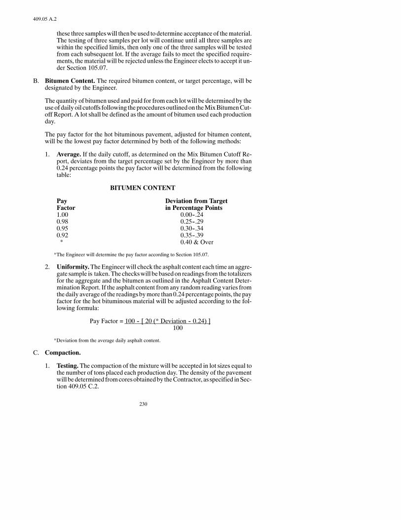
230
409.05 A.2
these three sampleswill thenbeused todetermine acceptance of thematerial.The testing of three samples per lot will continue until all three samples arewithin the specified limits, then only one of the three samples will be testedfrom each subsequent lot. If the average fails to meet the specified require-ments, thematerial will be rejected unless the Engineer elects to accept it un-der Section 105.07.
B. Bitumen Content. The required bitumen content, or target percentage, will bedesignated by the Engineer.
The quantity of bitumen used and paid for fromeach lotwill be determined by theuseofdailyoil cutoffs following theproceduresoutlinedon theMixBitumenCut-off Report. A lot shall be defined as the amount of bitumen used each productionday.
The pay factor for the hot bituminous pavement, adjusted for bitumen content,will be the lowest pay factor determined by both of the following methods:
1. Average. If the daily cutoff, as determined on the Mix Bitumen Cutoff Re-port, deviates from the target percentage set by the Engineer by more than0.24 percentage points the pay factor will be determined from the followingtable:
BITUMEN CONTENT
Pay Deviation from TargetFactor in Percentage Points1.00 0.00--.240.98 0.25--.290.95 0.30--.340.92 0.35--.39* 0.40 & Over
*The Engineer will determine the pay factor according to Section 105.07.
2. Uniformity.TheEngineerwill check the asphalt content each time an aggre-gate sample is taken.The checkswill be basedon readings from the totalizersfor the aggregate and the bitumen as outlined in the Asphalt Content Deter-minationReport. If the asphalt content from any random reading varies fromthedaily averageof the readingsbymore than0.24percentagepoints, thepayfactor for the hot bituminous material will be adjusted according to the fol-lowing formula:
Pay Factor = 100 -- [ 20 (* Deviation -- 0.24) ]100
*Deviation from the average daily asphalt content.
C. Compaction.
1. Testing. The compaction of themixture will be accepted in lot sizes equal tothe number of tons placed each production day. The density of the pavementwill bedetermined fromcoresobtainedby theContractor, as specified inSec-tion 409.05 C.2.

231
409.05 C.2
Each sublotwill beonepaverwidthwide, excluding the shoulders, 2,000 feetlong, and of the depth specified for the pavement course. If the partial sublotremaining at the end of a production day is 1,000 feet in length or longer, itwill be considered a separate sublot. If it is less than 1,000 feet long, it will beincluded in the last complete sublot. If the total day’s production is less than2,000 feet long (one paver width wide), that production will be considered alot.
Themean density of themainline pavement placed each production daywillbe the averageof thedensitiesof all of that day’s sublots. In addition to testingrandomly selected locations, theEngineer reserves the right to direct the test-ing of any areas which appear defective. Defective areas will be rejected un-less the Engineer elects to accept it under Section 105.07.
The Contractor, under the observation of the Engineer, shall:
a. Obtainmix samples frombehind the paver at random times specified bytheEngineer.One sample shall be takeneach timeanaggregate sample istaken; and
b. Compact threeMarshall specimenswith each sample taken to determinethe fieldMarshall density. The number of blows applied to theMarshallspecimens shall be 50, unless otherwise specified, and the temperatureof the mix shall be 270 plus or minus 5_F.; and
c. Determine the Maximum Theoretical Density of each sample taken.
The methods used to obtain the samples, compact the Marshall specimensand determine the Maximum Theoretical Density shall be as outlined in theDepartment’s Field Sampling and Testing Manual.
2. Contractor Coring. The Contractor shall take one core in each sublot at arandomlocationdeterminedby theEngineer andunder theobservationof theEngineer.After coringandsawing, the cores shall behandedover to theEngi-neer. The cores shall be taken adjacent to each other and the average of thetwo cores shall be used for determining the density of the sublot.
The Contractor shall take one additional full-depth core per mile, underobservation of the Engineer, for theDistrictMaterials Coordinator to use as anindependent assurance test. TheDistrictMaterials Coordinator will determinethe locationsof these cores.The cores shall bemarkedanddelivered to theDis-trict Materials Laboratory. The cores shall not be sawed by the Contractor.
The coring machine shall cut a cylindrical sample in the compacted asphaltlift without disturbing the density of the sample. The core samples shall be 4to 6 inches in diameter. Themasonry sawshall cut the core sample soonly thecompacted layer to be tested is removed; and the core is in a condition suit-able for testing.
Coringof eachday’spaving shall be completedno later than thenextworkingday following the placement of the lift. Cores shall be taken through the fulldepthof the in-place asphalt pavement.The surfaceof theoutsideof thecoresshall be smoothwith no distortion of the cylindrical shape or displacement of
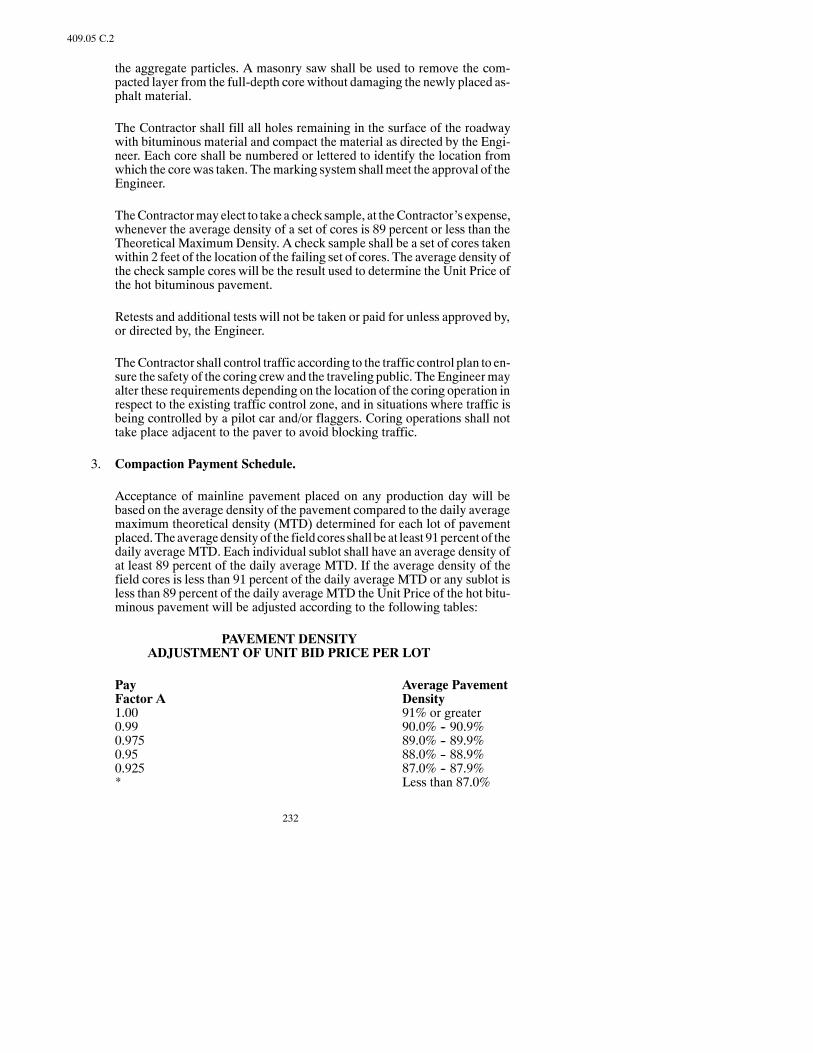
232
409.05 C.2
the aggregate particles. A masonry saw shall be used to remove the com-pacted layer from the full-depth core without damaging the newly placed as-phalt material.
The Contractor shall fill all holes remaining in the surface of the roadwaywith bituminous material and compact the material as directed by the Engi-neer. Each core shall be numbered or lettered to identify the location fromwhich the corewas taken. Themarking system shallmeet the approval of theEngineer.
TheContractormayelect to take a check sample, at theContractor’s expense,whenever the average density of a set of cores is 89 percent or less than theTheoretical MaximumDensity. A check sample shall be a set of cores takenwithin 2 feet of the location of the failing set of cores. The average density ofthe check sample cores will be the result used to determine the Unit Price ofthe hot bituminous pavement.
Retests and additional tests will not be taken or paid for unless approved by,or directed by, the Engineer.
TheContractor shall control traffic according to the traffic control plan to en-sure the safety of the coring crew and the traveling public. TheEngineermayalter these requirements depending on the location of the coring operation inrespect to the existing traffic control zone, and in situations where traffic isbeing controlled by a pilot car and/or flaggers. Coring operations shall nottake place adjacent to the paver to avoid blocking traffic.
3. Compaction Payment Schedule.
Acceptance of mainline pavement placed on any production day will bebased on the average density of the pavement compared to the daily averagemaximum theoretical density (MTD) determined for each lot of pavementplaced.Theaveragedensityof the fieldcores shall be at least 91percent of thedaily averageMTD. Each individual sublot shall have an average density ofat least 89 percent of the daily average MTD. If the average density of thefield cores is less than 91 percent of the daily average MTD or any sublot isless than 89 percent of the daily averageMTD the Unit Price of the hot bitu-minous pavement will be adjusted according to the following tables:
PAVEMENT DENSITYADJUSTMENT OF UNIT BID PRICE PER LOT
Pay Average PavementFactor A Density1.00 91% or greater0.99 90.0% -- 90.9%0.975 89.0% -- 89.9%0.95 88.0% -- 88.9%0.925 87.0% -- 87.9%* Less than 87.0%

233
409.06 A
Pay Lowest Density ofFactor B any Sublot1.00 89% or greater0.99 88.0% -- 88.9%0.98 87.0% -- 87.9%0.97 86.0% -- 86.9%0.96 85.0% -- 85.9%* Less than 85.0%
*The Engineer will determine whether the material may remain in place. The Pay Factor for thematerial allowed to remain in place shall be 0.70 for Pay Factor A and 0.80 for Pay Factor B.
The density of the field cores will be determined according to the Depart-ment’sField Sampling and TestingManual. The Total Pay Factorwill be theproduct of the pay factor for the average pavement density and the lowestsublot.
TOTAL PAY FACTOR = (PAY FACTOR A) × (PAY FACTOR B)
D. General.
The Contractor’s Quality Control test results will be used for acceptance if theyare within acceptable tolerances. A table for comparison of Verification Testingand Quality Control Testing is located in the Department’s Field Sampling andTesting Manual.
TheContractor’sQualityControlProgramwill be conductedbyqualifiedperson-nel as outlined in the applicable Department Transportation Certification Pro-gram.
If the resultsof theDepartment’sverification samplingand testingprogramdonotagree with the QC sampling and testing as performed by the Contractor, the De-partment, or its Representative, will conduct a review of the quality control andverification procedures, calculations, and equipment to determine the cause ofdiscrepancy.
E. Dispute Resolution Program.
If the cause of disagreement between the verification and quality control resultscannot be determined, the dispute resolution process as outlined in the Depart-ment’s Field Sampling and Testing Manual will be implemented.
409.06 METHOD OF MEASUREMENT.
The estimated quantities provided may be adjusted by the Engineer in the field. Anyincrease or decrease in the quantities used shall not be a basis for renegotiation in theprice bid for these items.
A. Hot Bituminous Pavement.Hot Bituminous Pavement will be measured by theTon or SquareYard according to Section 109. Batchweightswill not be permittedas amethodofmeasurement unless the plant is equippedwith an automatic batch-ing and weighing system with an automatic printer system which prints theweights of each batch and issues aweigh ticket for each load. The tonnagewill be

234
409.06 B
the weight used in the accepted pavement and no deduction will be made for theweight of bitumen used in the mixture.
B. Bitumen.Bitumenwill bemeasured according to Section 109 and the quantity ofbitumen will be the number of Tons or Gallons used in the accepted work.
C. CoredSample.Each individual cored sample that is removed in the requiredcon-ditionwill bemeasuredasaunit.Theworkvehicle, coringmachine,masonrysaw,and shadow vehicle will not bemeasured for payment, but will be included in themeasurement of the cored sample.
D. Testing. All cost incurred for the Quality Control Testing, and contractor devel-opedmix designwhen specified on thePlans,will not bemeasured separately andshall be included in the price bid for other items.
409.07 BASIS OF PAYMENT.
Payment will be made at the Contract Unit Price for the following:
Pay Item Pay UnitHot Bituminous Pavement QC/QA TonAsphalt Cement Ton or GallonCored Sample Each
This payment will be full compensation for all labor, equipment, andmaterials neces-sary to complete the work.
When price adjustments are required for failingmaterial or patching, payment will bemade as follows:
A. Determination of the payment adjustment of a lot of bituminous mixture will bemade by successivelymultiplying the Contract Unit Price per Ton of the bid itemby the applicable pay factors as determined in Sections 409.05 A, 409.05 B, and409.05 C.
B. When the averageof the test results specified inSection409.05A.2 showsa largershale content than the maximum allowable specified, the following deductionfrom the Bid Price for the bituminous mixture item will be made:
One percent reduction in unit price for each 0.2 percent above the maximum al-lowable percentage. If the percentage of shale exceeds the allowable limits by 2percentormore, thematerialwill be rejectedunless theEngineer elects to accept itunder Section 105.07.
This reductionwill apply to lots of 10,000 tons, andwill be applied independentlyof Section 409.05 A.1
C. Material for patching or leveling of an existing bituminous surface constructedunder apreviousContract shall beobtained from the tonnageprovided in thebasisof estimate and will be paid according to Section 408.07 C.
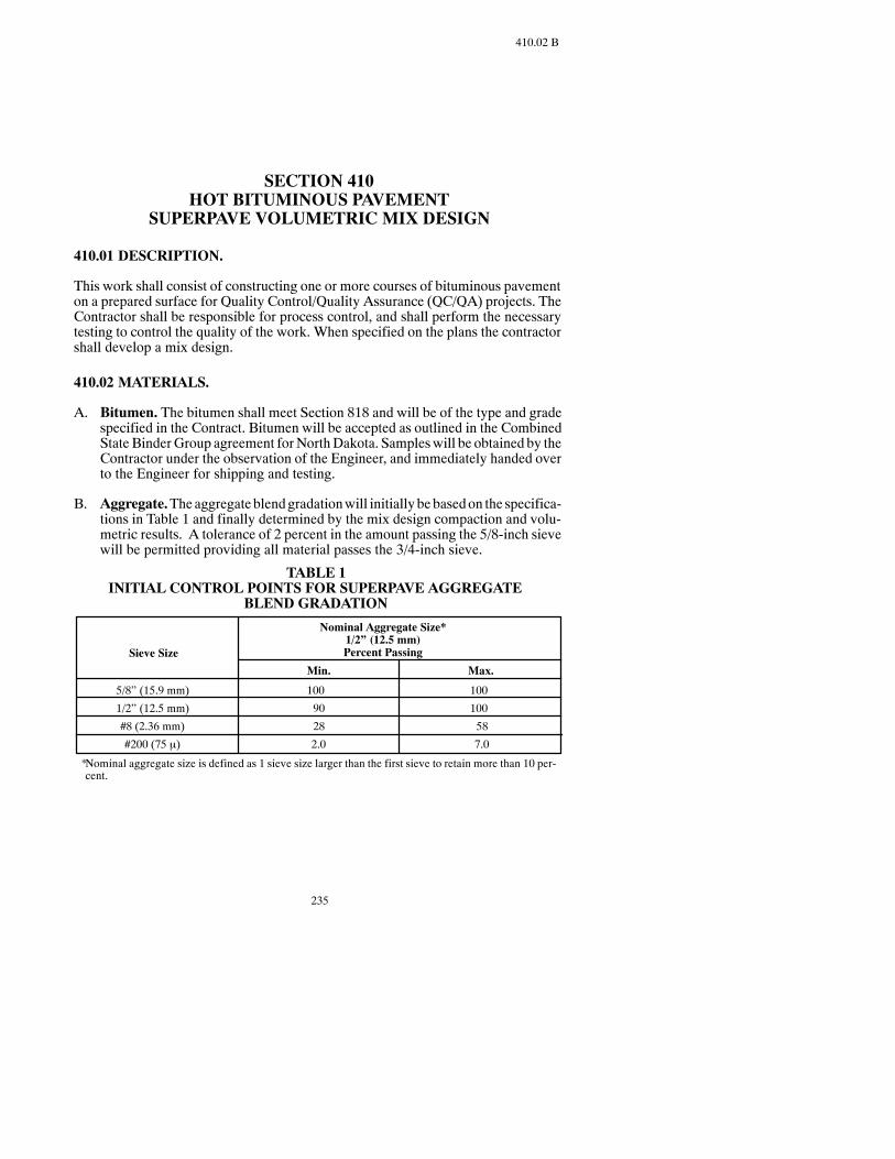
235
410.02 B
SECTION 410HOT BITUMINOUS PAVEMENT
SUPERPAVE VOLUMETRIC MIX DESIGN
410.01 DESCRIPTION.
This work shall consist of constructing one or more courses of bituminous pavementon a prepared surface for Quality Control/Quality Assurance (QC/QA) projects. TheContractor shall be responsible for process control, and shall perform the necessarytesting to control the quality of the work. When specified on the plans the contractorshall develop a mix design.
410.02 MATERIALS.
A. Bitumen. The bitumen shall meet Section 818 and will be of the type and gradespecified in the Contract. Bitumen will be accepted as outlined in the CombinedState BinderGroup agreement forNorthDakota. Sampleswill be obtained by theContractor under the observation of the Engineer, and immediately handed overto the Engineer for shipping and testing.
B. Aggregate.Theaggregate blendgradationwill initiallybe basedon the specifica-tions in Table 1 and finally determined by the mix design compaction and volu-metric results. A tolerance of 2 percent in the amount passing the 5/8-inch sievewill be permitted providing all material passes the 3/4-inch sieve.
TABLE 1INITIAL CONTROL POINTS FOR SUPERPAVE AGGREGATE
BLEND GRADATION
Nominal Aggregate Size*1/2” (12.5 mm)Percent PassingSieve Size
Min. Max.
5/8” (15.9 mm)
1/2” (12.5 mm)
#8 (2.36 mm)
#200 (75 μ)
100
90
28
2.0
100
100
58
7.0
*Nominal aggregate size is defined as 1 sieve size larger than the first sieve to retain more than 10 per-cent.

236
410.02 B
The Superpave aggregate shall meet the requirements of Table 2.
TABLE 2AGGREGATE TESTING CRITERIA
Test
Coarse AggregateAngularity, %
Fine AggregateAngularity, %
Clay Content% Sand Equivalent
Flat & ElongatedParticles, %
Toughness,% Loss
Lightweight Piecesin Aggregate,% Shale
Deleterious Materials% Spall
Criteria Reference/Comments
As specified on Plans
As specified on Plans
40 minimum
10 maximum
40 maximum
5 maximum
1.0 maximum
NDDOT Field Sampling and Testing Manual,the requirement is for 1 fractured face
AASHTO T 304, the criteria are % air voidsin loosely compacted fine aggregate
AASHTO T 176
ASTM D 4791
AASHTO T 96
AASHTO T 113, NDDOT Modified
AASHTO T 112, “Clay Lumps andFriable Particles in Aggregate”
410.03 EQUIPMENT.
Equipment shall be as specified in Section 408.03.
410.04 CONSTRUCTION REQUIREMENTS.
GENERAL
Contractor Quality Control. Quality Control (QC) will be the responsibility of theContractor. TheContractorwill performquality control sampling, testing, and inspec-tionduring all phases of theworkat a rate sufficient to assure that thework conforms totheContract requirements.TheContractor shall haveat least onepersonon theproject,at all times who is certified as an asphalt mix controller and one person certified as anaggregate lab and asphalt mix tester. The inspector shall be certified as an AsphaltPavement Inspector.Certification requirementswill beasoutlined in theDepartment’sTransportation Certification Program (TCP). If the Prime Contractor sublets any por-tion of the Contract, including aggregate production, to a Subcontractor, the Subcon-tractor shall have a person certified as an asphalt mix controller on the project. If theSubcontractor doesnothave acertifiedperson, thePrimeContractor’s certifiedpersonshall be on the Project and be in charge of quality control.
Quality Control Plan. Prior to beginningwork the Contractor will submit a “QualityControl Plan” to theEngineer. ThePlanwill contain: 1) the names andphonenumbersof the individual(s) responsible for the Contractor’s quality control program; 2) a list-ing of the technician(s) responsible for the quality control testing; 3) an organizationalchart indicating lines of authority (including names and phone numbers); 4) a summaryof the qualifications of the Quality Control Technicians, and 5) Details of the contrac-tor’s quality control plan addressing but not limited to the following items: 1) pit op-

237
410.04 A
erations andmethods used to control uniformity, reducing segregation, and efficientlyutilizing the aggregate resources of the pit; 2) plant operations discussing proposedequipment (number of bins, plant type, etc.) and method of operations; 3) testing fre-quencyandhowthismeets the intentof theSpecialProvision; and4)discussionofhowtheContractor’s quality control programwill respond to the need for corrective actionas defined in Section 410.04 Q.
TheDepartmentwill provide theContractorwith: 1) the names and phone numbers ofthe individual(s) responsible forproject administration;2) a listingof the technician(s)responsible for the quality assurance testing; and 3) an organizational chart indicatinglines of authority (including names and phone numbers).
QualityControl Laboratory.TheContractor will provide amaterials tester certifiedas an aggregate lab and asphalt mix tester to perform all testing including all testingduring aggregate production. TheContractor shall also provide testing equipment thatmeets the requirements for all tests called for by Specification. This laboratorywill bemeasured and paid according to Section 706.
The Contractor will furnish andmaintain a Type C laboratory at the plant as specifiedin Section 706 of the Standard Specifications. Any other laboratory location must beapproved by the Engineer. The laboratorywill be furnishedwith the necessary equip-ment and supplies for performing theContractor’sQC testing andmix design if speci-fied on the plans, including a Superpave Gyratory Compactor meeting all FHWA andAASHTO T 312 requirements. During production of the aggregate, the Contractormay furnish a lab equippedwith the necessary equipment to perform the following ag-gregate tests: bulkandapparent specificgravity, gradationanalysis, lightweightpiecesof aggregate, plastic index, and fractured faces. The Type C laboratory must be set upand ready to use before the paving operation begins.
Engineer’sLaboratory. TheContractorwill provide an additional TypeC laboratoryto be used during actualmix productionby theDepartment’s aggregate lab and asphaltmix tester. The testing equipment will be provided by the Department. The lab will beset up at the plant prior to production of the bituminous mix and be made available totheEngineer forQualityAssurance testing.TheContractor and theEngineerwill sharethe Gyratory Compactor provided for the Contractor’s lab. This laboratory will bemeasured and paid according to Section 706.
A. Pit Operations and Stockpiling of Aggregate. During production of theaggregate, the aggregate will be tested for gradation, fine aggregate angularity,lightweight piecesof aggregate, flat andelongatedpieces, coarse aggregate angu-larity and clay content. The testing frequency for gradation will be one test per1,000 tons of material produced for each aggregate stockpile. The testing fre-quency for lightweight pieces of aggregate, flat and elongated pieces and coarseaggregate angularitywill be the average of three randomcomposite samples fromthe first 5,000 tons ofmaterial produced. The testing frequency for the fine aggre-gate angularity and clay contentwill be the averageof three randomsamples fromthe first 5,000 tons of material produced from each stockpile. The fine aggregateangularity andclay content fromeach stockpilewill be combined todetermine thefinal blend results. If all three samples pass, the testing frequency will change toone of three samples tested for each 10,000 tons ofmaterial produced. If a samplefails, the remaining two sampleswill be tested and averaged for acceptance of thatlot. The testing frequency will then revert to the average of three tests per 5,000tons until all three samples pass, then one of three samples will be tested for each10,000 tons.

238
410.04 A
During the firstweekof aggregate production, for eachclass of aggregate, as soonas the Contractor determines the aggregate is representatives, and prior to theinitial mix design, the Contractor shall obtain a 90-pound sample of eachaggregate component. The Contractor shall split the samples under theobservation of theEngineer.One-half of each aggregate samplewill be submittedto the Engineer for testing. The Contractor and the Engineer will test the samplesto determine the bulk (dry) and apparent specific gravity and the percent waterabsorptionbydryweight of aggregate. The testingwill be completed according toAASHTOT84, T 85 and the procedures in theDepartment’sField Sampling andTestingManual. One testwill be performed for each 10,000 ton of each aggregatecomponent produced.Aminimumof two testswill be required for eachaggregatecomponent. Testing shall commence within two working days of sampling. Testresultswill be reported to eachparty as soon as they are available. If the individualspecific gravity values determined by the Contractor and the Departmentcorrelate within 0.040, the average of the Contractor’s numbers will be used tocalculate the absorption, fines to asphalt ratio, and voids in mineral aggregate(VMA). If the individual specificgravityvaluesdeterminedby theContractor andthe Department do not correlate within the allowable tolerance (0.040), or if theContractor fails to supply an aggregate that meets the mix design criteria then:
-- The mix design will not be approved and mix production will be begin.
-- The Contractor has the option of running the test together with Departmentpersonnel at the District Lab and use those results, or testing differences canbe resolved according to the procedures in the Department’sField Samplingand Testing Manual.
1. Department-DevelopedMixDesign.TheDepartmentwill develop themixdesign unless the plans specify that the Contractor shall develop the mix de-sign.
a. After 10,000 tons of material is produced, the Contractor will providethe Department with an aggregate sample representing each stockpileand asphalt required for the mix design. The Contractor shall develop apreliminary gyratory mix design and submit the results to the Depart-ment. This mix design is for informational purposes to assure the Con-tractor has produced specified material. The Department will developthemix design for the project. The Contractor shall provide all of the in-formation required for the JMF, except StandardR30,MixConditioningof Hot Mix Asphalt (HMA).
b. When the Department’s mix design is approved and testing indicatesuniform results for fine aggregate angularity, flat/elongated pieces orcourse aggregate angularity, and both parties are confident that futureproduction will remain within the specifications, the Engineer, by writ-ten notice, may reduce the frequency of the tests.
2. Contractor Developed Mix Design. The Plans will specify when the con-tractor shall develop the mix design.
a. After production of 5,000 tons and before production of 10,000 tons ofaggregate, theContractor shall developapreliminarySuperpavemixde-sign and submit the results to the Department. This preliminary mix de-

239
410.04 B
sign is for informational purposes to assure theContractor has producedspecified material. The Contractor shall provide all of the informationrequired for the JMF, except Standard R30, Mix Conditioning of HotMix Asphalt (HMA).
b. After 10,000 tonofmaterial is produced theContractor shall develop themix design for the project.
c. When theContractor’smix design is approved by the Engineer and test-ing indicates uniform results for fine aggregate angularity, flat/elon-gated pieces or course aggregate angularity, and both parties are confi-dent that future productionwill remainwithin the specifications, theEn-gineer, by written notice, may reduce the frequency of the tests.
The Contractor will sample and test the aggregate according to the proce-dures of the Department’s Field Sampling and Testing Manual.
The Contractor will provide the Engineer with copies of the test results foreach stockpile of aggregate that will be incorporated into the mix by noon ofthe followingday the tests are completed. The test reportswill include resultsfor gradation, fine aggregate angularity, lightweight pieces of aggregate, flatand elongated pieces, coarse aggregate angularity, clay content and the bulkand apparent specific gravity.
If themix designmeets the properties specified andDepartment and the Contrac-tor mutually agree it is necessary to adjust the aggregate production operation toproduce an aggregate thatwill improve themixdesignproperties, theDepartmentwill negotiate an equitable adjustment with the Contractor to produce an aggre-gate that meets the desired mix design properties.
B. VolumetricMixDesign.Themixdesign usedwill be a labmix design developedby the Department or developed by the Contractor, when specified on the Plans,and approved by the Department. The mix design procedures shall be performedaccording to the AASHTO Standards outlined in Table 3.
When theDepartmentdevelops themixdesign theContractorwill provide amini-mumof165pounds (75kg) of each stockpile and ten1- liter cansof thePGbinder,AC specific gravity, and supplier to be used on the project at least 30 days prior toproduction. A sample tag identifying the project number and pit location shall beattached to each sample. TheDepartmentwill then have twoweeks to return a JobMix Formula (JMF) to the Contractor.
Whenmaking theblenddeterminations for themixdesign, thevalueused for eachsieve, from each stockpile, shall be the average of the production samples.
The mix design process will consist of two separate mix design procedures. Thefirstwill be aTrialMixDesign, the secondwill be the FinalMixDesign. TheTrial
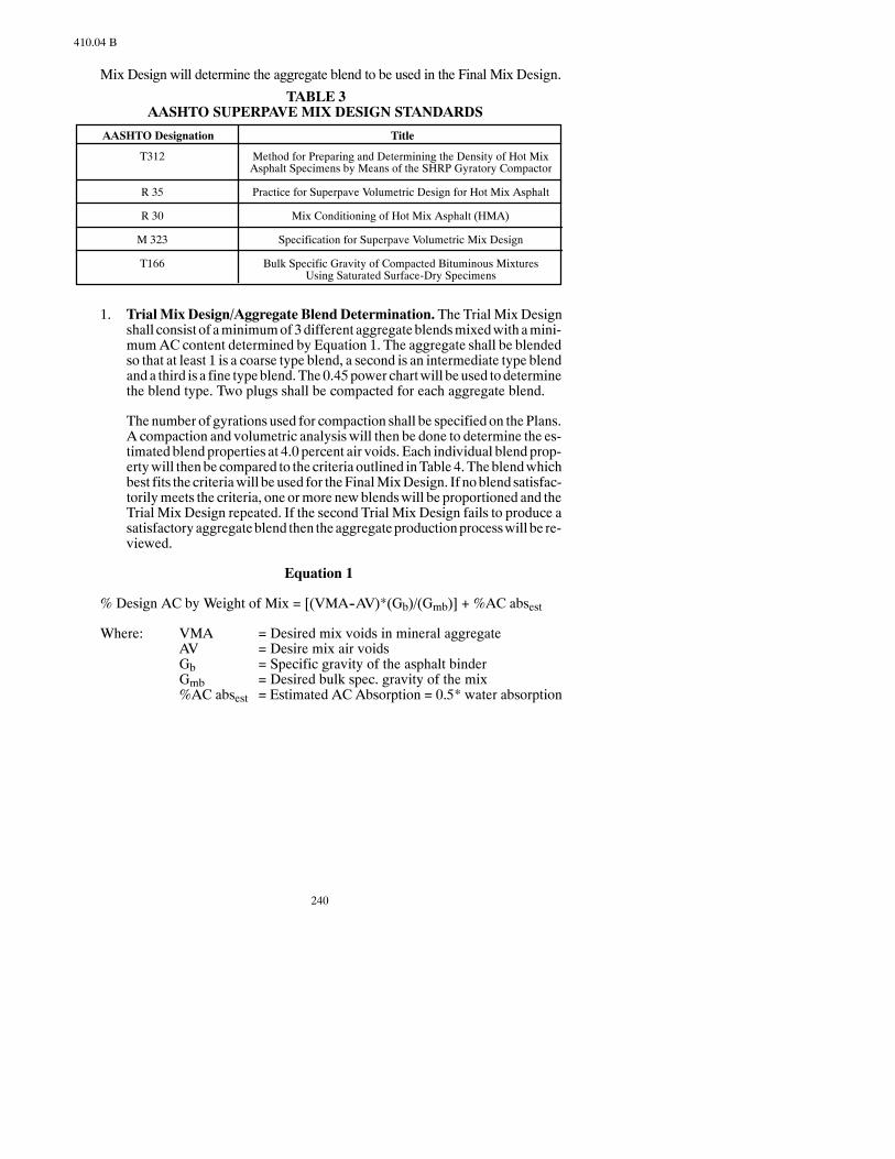
240
410.04 B
Mix Design will determine the aggregate blend to be used in the Final Mix Design.
TABLE 3AASHTO SUPERPAVE MIX DESIGN STANDARDS
AASHTO Designation
T312
R 35
R 30
M 323
T166
Title
Method for Preparing and Determining the Density of Hot MixAsphalt Specimens by Means of the SHRP Gyratory Compactor
Practice for Superpave Volumetric Design for Hot Mix Asphalt
Mix Conditioning of Hot Mix Asphalt (HMA)
Specification for Superpave Volumetric Mix Design
Bulk Specific Gravity of Compacted Bituminous MixturesUsing Saturated Surface-Dry Specimens
1. TrialMix Design/Aggregate BlendDetermination. The Trial Mix Designshall consist of aminimumof3different aggregate blendsmixedwith amini-mumAC content determined by Equation 1. The aggregate shall be blendedso that at least 1 is a coarse type blend, a second is an intermediate type blendanda third is a fine typeblend.The0.45power chartwill beused todeterminethe blend type. Two plugs shall be compacted for each aggregate blend.
The number of gyrations used for compaction shall be specified on thePlans.A compaction and volumetric analysis will then be done to determine the es-timated blend properties at 4.0 percent air voids. Each individual blend prop-ertywill thenbe compared to the criteria outlined inTable 4. Theblendwhichbest fits the criteriawill be used for theFinalMixDesign. If noblend satisfac-torilymeets the criteria, one ormore newblendswill be proportioned and theTrial Mix Design repeated. If the second Trial Mix Design fails to produce asatisfactoryaggregateblend then theaggregateproductionprocesswill be re-viewed.
Equation 1
% Design AC by Weight of Mix = [(VMA--AV)*(Gb)/(Gmb)] + %AC absest
Where: VMA = Desired mix voids in mineral aggregateAV = Desire mix air voidsGb = Specific gravity of the asphalt binderGmb = Desired bulk spec. gravity of the mix%AC absest = Estimated AC Absorption = 0.5* water absorption
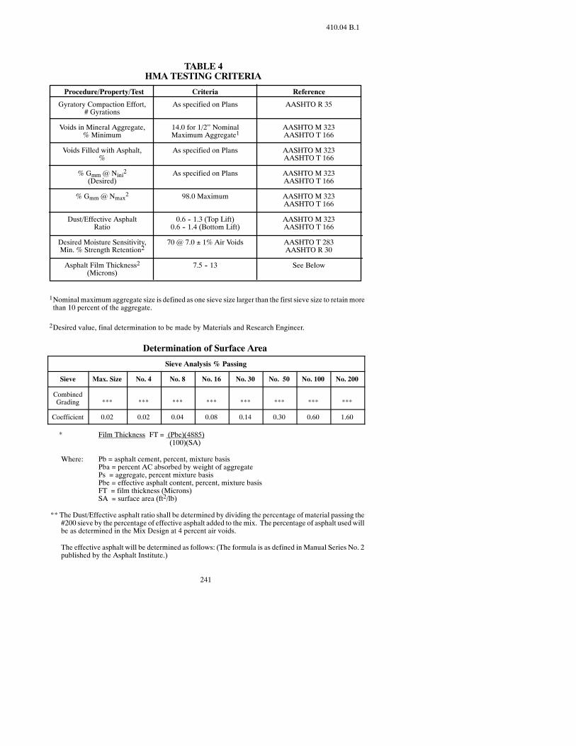
241
410.04 B.1
TABLE 4HMA TESTING CRITERIA
Procedure/Property/Test
Gyratory Compaction Effort,# Gyrations
Voids in Mineral Aggregate,% Minimum
Voids Filled with Asphalt,%
% Gmm @ Nini2(Desired)
% Gmm @ Nmax2
Dust/Effective AsphaltRatio
Desired Moisture Sensitivity,Min. % Strength Retention2
Asphalt Film Thickness2(Microns)
Criteria Reference
As specified on Plans
14.0 for 1/2” NominalMaximum Aggregate1
As specified on Plans
As specified on Plans
98.0 Maximum
0.6 -- 1.3 (Top Lift)0.6 -- 1.4 (Bottom Lift)
70 @ 7.0 ± 1% Air Voids
7.5 -- 13
AASHTO R 35
AASHTO M 323AASHTO T 166
AASHTO M 323AASHTO T 166
AASHTO M 323AASHTO T 166
AASHTO M 323AASHTO T 166
AASHTO M 323AASHTO T 166
AASHTO T 283AASHTO R 30
See Below
1Nominalmaximum aggregate size is defined as one sieve size larger than the first sieve size to retainmorethan 10 percent of the aggregate.
2Desired value, final determination to be made by Materials and Research Engineer.
Determination of Surface Area
Sieve Analysis % Passing
Sieve Max. Size No. 4 No. 8 No. 16 No. 30 No. 50 No. 100 No. 200
CombinedGrading *** *** *** *** *** *** *** ***
Coefficient 0.02 0.02 0.04 0.08 0.14 0.30 0.60 1.60
**** Film Thickness FT = (Pbe)(4885)(100)(SA)
Where: Pb = asphalt cement, percent, mixture basisPba = percent AC absorbed by weight of aggregatePs = aggregate, percent mixture basisPbe = effective asphalt content, percent, mixture basisFT = film thickness (Microns)SA = surface area (ft2/lb)
** The Dust/Effective asphalt ratio shall be determined by dividing the percentage of material passing the#200 sieve by the percentage of effective asphalt added to the mix. The percentage of asphalt usedwillbe as determined in the Mix Design at 4 percent air voids.
The effective asphalt will be determined as follows: (The formula is as defined in Manual Series No. 2published by the Asphalt Institute.)
242
410.04 B.1
Pbe = Pb -- (Pba)(Ps)100
*** The gradation used for calculating film thickness and dust/effective A.C. ratio will be the combinedgradation results of the actual material used to run the mix design. Perform calculations to the nearesthundredth and round to the nearest tenth.
2. Final Mix Design/Job Mix Formula Determination. After the Trial MixDesign is done, the FinalMixDesign is conducted. The aggregate blendusedshall be the blenddetermined to best fit Superpave criteria from theTrialMixDesign. FiveAC contentswill be used in the FinalMixDesign. TheAC con-tents used shall be:
a. The optimum AC content determined by the Trial Mix Design.
b. 0.5 percent below the optimumAC content determined by the TrialMixDesign.
c. 0.5 percent above the optimumAC content determined by the TrialMixDesign.
d. 1.0 percent below the optimumAC content determined by the TrialMixDesign.
e. 1.0 percent above the optimumAC content determined by the TrialMixDesign.
Aminimum of two specimens shall be compacted for each AC content. Thesame criteria for compaction and volumetric evaluation referenced for theTrial Mix Design are used.
Once the mix is evaluated, graphs representing Air Voids, VMA and VFAversus percent ACbinder are plotted. The designAC content is then selectedfor 4.0 percent air voids. The mix characteristics at the selected design ACcontent are then compared to the criteria for FineAggregate Angularity, Flatand Elongated Pieces, Clay Content, VMA, VFA, percent Gmm@Nini, per-cent Gmm@Nmax, and Dust/Asphalt Ratio outlined in Tables 3 and 5. If theresults meet the mix design criteria this mix then becomes the JMF.
If the results from the Final Mix Design do not meet the mix design criteriathen one of the two following options will be selected:
a. The Final Mix Design will be redone.
b. Start over with the Trial Mix Design.
3. Moisture Sensitivity Test.Once a JMF is determined a moisture sensitivitytest will be conducted on themix according to AASHTOT 283, “ResistanceofCompactedBituminousMixture toMoisture InducedDamage”. TheMar-shall specimens shall be compacted to 7.0 percent 1.0 percent air voids.The tensile strength ratio shall be a minimum of 70 percent.
4. Aggregate/AsphaltSuppliedOtherThanThatUsed in theMixDesign. Ifaggregate or asphalt is utilized from sources other than those initially sub-
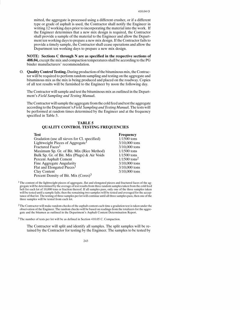
243
410.04 O
mitted, the aggregate is processed using a different crusher, or if a differenttype or grade of asphalt is used, the Contractor shall notify the Engineer inwriting 12working days prior to incorporating thematerial into the work. Ifthe Engineer determines that a new mix design is required, the Contractorshall provide a sample of the material to the Engineer and allow the Depart-ment tenworking days to prepare a newmix design. If the Contractor fails toprovide a timely sample, the Contractor shall cease operations and allow theDepartment ten working days to prepare a new mix design.
NOTE: Sections C through N are as specified in the respective sections of408.04, except themix and compaction temperatures shall be according to the PGbinder manufacturers’ recommendation.
O. QualityControlTesting.Duringproductionof the bituminousmix, theContrac-tor will be required to perform random sampling and testing on the aggregate andbituminous mix as the mix is being produced and placed on the roadway. Copiesof all test results will be furnished to the Engineer by noon the following day.
TheContractorwill sample and test the bituminousmix as outlined in theDepart-ment’s Field Sampling and Testing Manual.
TheContractorwill sample theaggregate fromthecold feedand test the aggregateaccording to theDepartment’sField Sampling andTestingManual. The testswillbe performed at random times determined by the Engineer and at the frequencyspecified in Table 5.
TABLE 5QUALITY CONTROL TESTING FREQUENCIES
Test FrequencyGradation (use all sieves for Cl. specified) 1/1500 tonsLightweight Pieces of Aggregate1 3/10,000 tonsFractured Faces1 3/10,000 tonsMaximum Sp. Gr. of Bit. Mix (Rice Method) 1/1500 tonsBulk Sp. Gr. of Bit. Mix (Plugs) & Air Voids 1/1500 tonsPercent Asphalt Cement 1/1500 tons2Fine Aggregate Angularity 3/10,000 tonsFlat and Elongated Pieces1 3/10,000 tonsClay Content 3/10,000 tonsPercent Density of Bit. Mix (Cores)3
1The content of the lightweight pieces of aggregate, flat and elongated pieces and fractured faces of the ag-gregatewill be determined by the average of test results from three random samples taken from the cold feedbelt for each lot of 10,000 tons or fraction thereof. If all samples pass, only one of the three samples takenwill be tested until a sample fails; then the remaining two samples will be tested and averaged for the accep-tance of that lot. The testing of three samples per lotwill continue until all three samples pass, then one of thethree samples will be tested from each lot.
2The Contractor will make random checks of the asphalt content each time a gradation test is taken under theobservation of the Engineer. The random checks will be based on readings from the totalizers for the aggre-gate and the bitumen as outlined in the Department’s Asphalt Content Determination Report.
3The number of tests per lot will be as defined in Section 410.05 C. Compaction.
The Contractor will split and identify all samples. The split samples will be re-tained by the Contractor for testing by the Engineer. The samples to be tested by
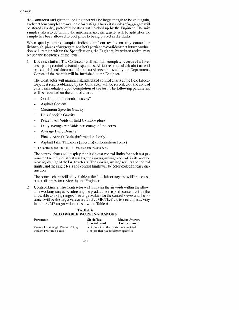
244
410.04 O
the Contractor and given to the Engineer will be large enough to be split again,such that four samplesare available for testing.Thesplit samplesof aggregatewillbe stored in a dry, protected location until picked up by the Engineer. The mixsamples taken to determine the maximum specific gravity will be split after thesample has been allowed to cool prior to being placed in the flasks.
When quality control samples indicate uniform results on clay content orlightweight pieces of aggregate; and both parties are confident that future produc-tion will remain within the Specifications, the Engineer, by written notice, mayreduce the frequency of the tests.
1. Documentation. The Contractor will maintain complete records of all pro-cessquality control tests and inspections.All test results and calculationswillbe recorded and documented on data sheets approved by the Department.Copies of the records will be furnished to the Engineer.
The Contractor will maintain standardized control charts at the field labora-tory. Test results obtained by the Contractor will be recorded on the controlcharts immediately upon completion of the test. The following parameterswill be recorded on the control charts:
-- Gradation of the control sieves*-- Asphalt Content-- Maximum Specific Gravity-- Bulk Specific Gravity-- Percent Air Voids of field Gyratory plugs-- Daily average Air Voids percentage of the cores-- Average Daily Density-- Fines / Asphalt Ratio (informational only)-- Asphalt Film Thickness (microns) (informational only)
*** The control sieves are the 1/2”, #4, #30, and #200 sieves.
The control charts will display the single-test control limits for each test pa-rameter, the individual test results, themoving average control limits, and themoving average of the last four tests. Themoving average results andcontrollimits, and the single tests and control limits will be color coded for easy dis-tinction.
The control chartswill be available at the field laboratory andwill be accessi-ble at all times for review by the Engineer.
2. Control Limits.TheContractor willmaintain the air voidswithin the allow-able working ranges by adjusting the gradation or asphalt content within theallowableworking ranges. The target values for the control sieves and the bi-tumenwill be the target values set for the JMF. The field test resultsmay varyfrom the JMF target values as shown in Table 6.
TABLE 6ALLOWABLEWORKING RANGES
Parameter Single Test Moving AverageControl Limit Control Limit1
Percent Lightweight Pieces of Aggr. Not more than the maximum specifiedPercent Fractured Faces Not less than the minimum specified

245
410.04 P
Fine Aggregate Angularity Not less than the minimum specifiedFlat and Elongated Pieces Not more than the maximum specifiedSand Quivalent Test Not less than the minimum specified1/2” and #4 Sieve 6 5#30 sieve 5 4#200 Sieve2 2.0 1.5Asphalt Content 0.30 0.24Air Voids (plugs) 2% to 6% 2.5% to 5%
1Average of last four tests
2Not to exceed the maximum specified.
3. Corrective Action. When a single-test control limit has been exceeded, theContractor will immediately re-sample and retest. If the re-sample exceedsthecontrol limits, corrective actionwill be institutedby theContractor imme-diately.After the corrective action, theContractor will immediately re--sampleand retest. The corrective action will be documented.
Immediate shutdown will result when two consecutive tests exceed thesingle-test control limits for percent Lightweight Pieces of Aggregate, FineAggregateAngularity,CoarseAggregateAngularity, or clay content.Opera-tions will resume when the Engineer is satisfied that corrective action has beentaken.
When the moving average values trend toward the moving-average controllimits, the Contractor will take corrective action and increase the samplingand testing rate. The corrective action will be documented.
When the moving average of the control sieves or the bitumen exceeds themoving-averagecontrol limits, theContractormaycontinueproduction if theair voidsarewithin thecontrol limits and thematerial passing thenumber200sieve does not exceed the maximum specified. The Contractor will take thenecessary corrective action to producemix based on the JMF or the Contrac-tor may request that new target values be set if the test results indicate thatadjustments to the target valuesarenecessary.TheContractormayonlymakethe changes requested with the approval of the Engineer.
When the moving average of the air voids exceeds the moving-average con-trol limit, the Contractor will immediately cease operations unless the Engi-neer is satisfied that the Contractor is taking corrective action. Quality con-trol testing will resume as soon as the plant has started and operations areequalized.
It will be the responsibility of the Contractor to shut down operations whenthe control limits are exceededas specified. Failure to ceaseoperations shall sub-ject all material produced after exceeding the control limits to be considered un-acceptable.
P. Verification Testing. The Engineer will conduct verification tests on indepen-dent samples. Cold feed belt, bitumen samples, sampling behind paver, and cor-ing will be sampled by the Contractor under the observation of the Engineer. TheEngineer will test at an increased rate during the first lot of production to de-termine the accuracyof the quality control testing. Frequencies for verification test-ing are located in theDepartment’sFieldSamplingandTestingManual. Test resultsperformed by the Engineer will be available to the Contractor.
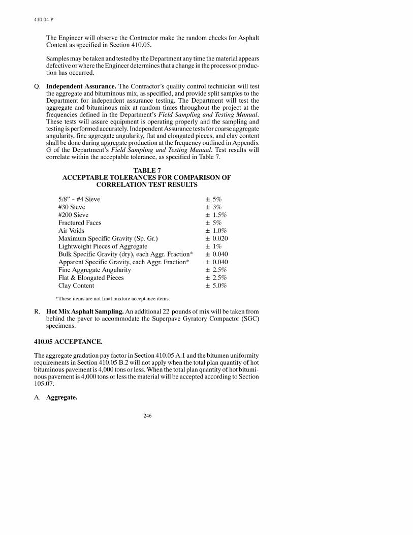
246
410.04 P
The Engineer will observe the Contractor make the random checks for AsphaltContent as specified in Section 410.05.
Samplesmaybe taken and testedby theDepartment any time thematerial appearsdefectiveorwhere theEngineer determines that a change in theprocessorproduc-tion has occurred.
Q. Independent Assurance. The Contractor’s quality control technician will testthe aggregate and bituminous mix, as specified, and provide split samples to theDepartment for independent assurance testing. The Department will test theaggregate and bituminous mix at random times throughout the project at thefrequencies defined in the Department’s Field Sampling and Testing Manual.These tests will assure equipment is operating properly and the sampling andtesting is performedaccurately. IndependentAssurance tests for coarse aggregateangularity, fine aggregate angularity, flat and elongated pieces, and clay contentshall be done during aggregate production at the frequency outlined in AppendixG of the Department’s Field Sampling and Testing Manual. Test results willcorrelate within the acceptable tolerance, as specified in Table 7.
TABLE 7ACCEPTABLE TOLERANCES FOR COMPARISON OF
CORRELATION TEST RESULTS
5/8” -- #4 Sieve 5%#30 Sieve 3%#200 Sieve 1.5%Fractured Faces 5%Air Voids 1.0%Maximum Specific Gravity (Sp. Gr.) 0.020Lightweight Pieces of Aggregate 1%Bulk Specific Gravity (dry), each Aggr. Fraction* 0.040Apparent Specific Gravity, each Aggr. Fraction* 0.040Fine Aggregate Angularity 2.5%Flat & Elongated Pieces 2.5%Clay Content 5.0%
*These items are not final mixture acceptance items.
R. HotMixAsphalt Sampling.An additional 22 pounds ofmixwill be taken frombehind the paver to accommodate the Superpave Gyratory Compactor (SGC)specimens.
410.05 ACCEPTANCE.
The aggregate gradation pay factor in Section 410.05A.1 and the bitumen uniformityrequirements in Section 410.05 B.2 will not apply when the total plan quantity of hotbituminous pavement is 4,000 tons or less.When the total plan quantity of hot bitumi-nous pavement is 4,000 tons or less thematerial will be accepted according to Section105.07.
A. Aggregate.

247
410.05 A.2
1. Gradation. Aggregate will be sampled and tested in lot sizes equal to thenumber of tons placed each production day. The aggregate gradation speci-fied will be the basis of acceptance.
The Contractor shall obtain all aggregate samples at random times deter-mined by and under the observation of the Engineer. The samples shall betaken from the cold feed belt according to AASHTO T 2, Section 4.3.1 or4.3.2. The sample shall be split into two representative samples, numberedand bagged by the Contractor under the observation of the Engineer. Bothhalves of the sample shall be submitted to the Engineer. The untested half ofthe sample will be retained by the Engineer for 24 hours after the test resultsare made known to the Contractor. Either party may request that the secondhalf of the sample be tested within this 24-hour time frame. The test resultsfrom this retest shall replace the test values of the initial test.
Oneaggregate samplewill be taken for each1,500 tonofmixproducedwithaminimum of one sample per day. Payment for the mix represented by thesamples will be based on the uniformity of the test results.
If any two consecutive tests vary from the JMF gradation target value set foreach sieve bymore than the tolerances listed below, the pay factor for the fulldays productionwill be the lowest pay factor determined from the followingformula:
Pay Factor = 100 -- Deviation from the Target Range*100
*Target Range = target value + or -- the acceptable tolerance value
Acceptance of the aggregatewill be based on the target values for the controlsieves and the allowable working range for the single test control limit asshown in Section 410.04 O Table 6.
If the averagedaily air voids of the gyratory specimens are not between2per-cent and 5 percent and the material fails to meet the specifications for twoconsecutive lots, theContractor shall not incorporate any additionalmaterialinto the work until the Engineer is satisfied that the Contractor is taking thenecessary corrective action to meet the Specifications. The Engineer mayrequest that a newmixdesignbedeveloped if theContractor isunable tomeetthe Specifications.
2. AdditionalAggregateTests.Aggregate samples todetermine shale content,plasticity index, fractured faces, and L. A. Abrasion loss will be taken by theContractor, under theobservationof theEngineer, before theadditionofbitu-men to the mix.
The shale content and plasticity index of the aggregatewill be determined bythe average of test results from three random samples taken from the coldfeed belt fromeach lot of 10,000 tons or fraction thereof. The sampleswill betested and the material will be accepted if the average of the three samplesmeets the specified requirements. If each of the samples is within the speci-fied limits, only one of the three sampleswill be tested from each subsequentlot. If at any time the sample tested does notmeet the specified requirements,
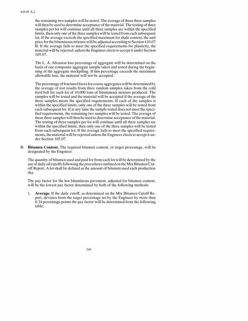
248
410.05 A.2
the remaining two sampleswill be tested. The average of these three sampleswill then be used to determine acceptance of thematerial. The testing of threesamples per lot will continue until all three samples are within the specifiedlimits, then only one of the three sampleswill be tested fromeach subsequentlot. If the average exceeds the specified maximum for shale content, the unitprice for thebituminousmixturewill be adjusted according toSection410.07B. If the average fails to meet the specified requirements for plasticity, thematerialwill be rejected, unless theEngineer elects to accept it under Section105.07.
The L. A. Abrasion loss percentage of aggregate will be determined on thebasis of one composite aggregate sample taken and tested during the begin-ning of the aggregate stockpiling. If this percentage exceeds the maximumallowable loss, the material will not be accepted.
Thepercentageof fractured faces for coarseaggregateswill bedeterminedbythe average of test results from three random samples taken from the coldfeed belt for each lot of 10,000 tons of bituminous mixture produced. Thesamples will be tested and the material will be accepted if the average of thethree samples meets the specified requirements. If each of the samples iswithin the specified limits, only one of the three samples will be tested fromeach subsequent lot. If at any time the sample tested does not meet the speci-fied requirements, the remaining two samples will be tested. The average ofthese three sampleswill thenbeused todetermine acceptance of thematerial.The testing of three samples per lot will continue until all three samples arewithin the specified limits, then only one of the three samples will be testedfrom each subsequent lot. If the average fails to meet the specified require-ments, thematerial will be rejected unless the Engineer elects to accept it un-der Section 105.07.
B. Bitumen Content. The required bitumen content, or target percentage, will bedesignated by the Engineer.
The quantity of bitumen used and paid for fromeach lotwill be determined by theuseofdailyoil cutoffs following theproceduresoutlinedon theMixBitumenCut-off Report. A lot shall be defined as the amount of bitumen used each productionday.
The pay factor for the hot bituminous pavement, adjusted for bitumen content,will be the lowest pay factor determined by both of the following methods:
1. Average. If the daily cutoff, as determined on the Mix Bitumen Cutoff Re-port, deviates from the target percentage set by the Engineer by more than0.24 percentage points the pay factor will be determined from the followingtable:
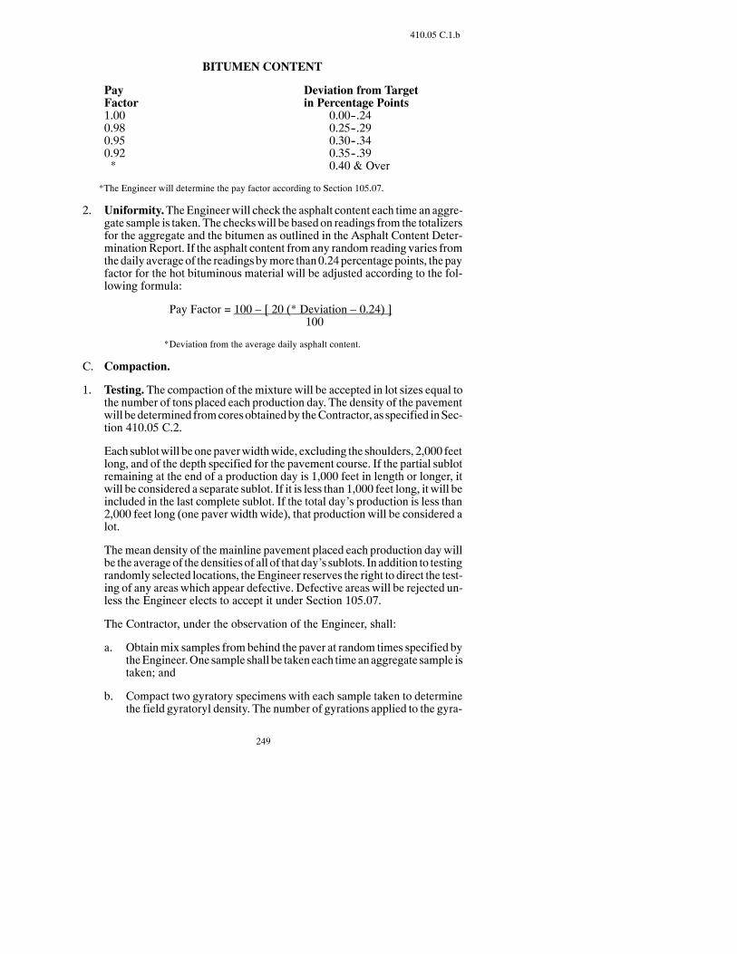
249
410.05 C.1.b
BITUMEN CONTENT
Pay Deviation from TargetFactor in Percentage Points1.00 0.00--.240.98 0.25--.290.95 0.30--.340.92 0.35--.39* 0.40 & Over
*The Engineer will determine the pay factor according to Section 105.07.
2. Uniformity.TheEngineerwill check the asphalt content each time an aggre-gate sample is taken. The checkswill be based on readings from the totalizersfor the aggregate and the bitumen as outlined in the Asphalt Content Deter-minationReport. If the asphalt content from any random reading varies fromthedaily averageof the readingsbymore than0.24percentagepoints, thepayfactor for the hot bituminous material will be adjusted according to the fol-lowing formula:
Pay Factor = 100 – [ 20 (* Deviation – 0.24) ]100
*Deviation from the average daily asphalt content.
C. Compaction.
1. Testing. The compaction of themixture will be accepted in lot sizes equal tothe number of tons placed each production day. The density of the pavementwill bedetermined fromcoresobtainedby theContractor, as specified inSec-tion 410.05 C.2.
Each sublotwill beonepaverwidthwide, excluding the shoulders, 2,000 feetlong, and of the depth specified for the pavement course. If the partial sublotremaining at the end of a production day is 1,000 feet in length or longer, itwill be considered a separate sublot. If it is less than 1,000 feet long, it will beincluded in the last complete sublot. If the total day’s production is less than2,000 feet long (one paver width wide), that production will be considered alot.
Themean density of themainline pavement placed each production daywillbe the averageof thedensitiesof all of that day’s sublots. In addition to testingrandomly selected locations, theEngineer reserves the right to direct the test-ing of any areas which appear defective. Defective areas will be rejected un-less the Engineer elects to accept it under Section 105.07.
The Contractor, under the observation of the Engineer, shall:
a. Obtainmix samples frombehind the paver at random times specified bytheEngineer.One sample shall be takeneach timeanaggregate sample istaken; and
b. Compact two gyratory specimens with each sample taken to determinethe field gyratoryl density. The number of gyrations applied to the gyra-

250
410.05 C.1.b
tory specimens shall be as specified in the Plans or as specified by theEngineer, and the temperature of the mix shall be 270_F plus or minus5_F.; and
c. Determine the Maximum Theoretical Density of each sample taken.
Themethodsused toobtain the samples, compact thegyratory specimensanddetermine the Maximum Theoretical Density shall be as outlined in the De-partment’s Field Sampling and Testing Manual.
2. Contractor Coring. The Contractor shall take one core in each sublot at arandomlocationdeterminedby theEngineer andunder theobservationof theEngineer.After coringandsawing, the cores shall behandedover to theEngi-neer. The cores shall be taken adjacent to each other and the average of thetwo cores shall be used for determining the density of the sublot.
The Contractor shall take one additional full-depth core per mile, underobservation of the Engineer, for the District Materials Coordinator to use asan independent assurance test. TheDistrictMaterialsCoordinatorwill deter-mine the locations of these cores. The cores shall bemarked and delivered tothe District Materials Laboratory. The cores shall not be sawed by the Con-tractor.
The coring machine shall cut a cylindrical sample in the compacted asphaltlift without disturbing the density of the sample. The core samples shall be 4to 6 inches in diameter. Themasonry sawshall cut the core sample soonly thecompacted layer to be tested is removed; and the core is in a condition suit-able for testing.
Coringof eachday’spaving shall be completedno later than thenextworkingday following the placement of the lift. Cores shall be taken through the fulldepthof the in-place asphalt pavement.The surfaceof theoutsideof thecoresshall be smoothwith no distortion of the cylindrical shape or displacement ofthe aggregate particles. A masonry saw shall be used to remove the com-pacted layer from the full-depth core without damaging the newly placed as-phalt material.
The Contractor shall fill all holes remaining in the surface of the roadwaywith bituminous material and compact the material as directed by the Engi-neer. Each core shall be numbered or lettered to identify the location fromwhich the corewas taken. Themarking system shallmeet the approval of theEngineer.
TheContractormayelect to take a check sample, at theContractor’s expense,whenever the average density of a sublot is 89 percent or less than theTheoretical MaximumDensity. A check sample shall be a set of cores takenwithin two feet of the location of the failing set of cores. The average densityof the check sample coreswill be the result used todetermine theUnitPriceofthe hot bituminous pavement.
Retests and additional tests will not be taken or paid for unless approved by,or directed by, the Engineer.
TheContractor shall control traffic according to the traffic control plan to en-sure the safety of the coring crew and the traveling public. TheEngineermay
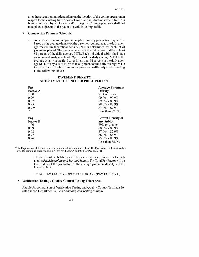
251
410.05 D
alter these requirements depending on the location of the coring operation inrespect to the existing traffic control zone, and in situations where traffic isbeing controlled by a pilot car and/or flaggers. Coring operations shall nottake place adjacent to the paver to avoid blocking traffic.
3. Compaction Payment Schedule.
a. Acceptance of mainline pavement placed on any production daywill bebasedon theaveragedensityof thepavementcompared to thedailyaver-age maximum theoretical density (MTD) determined for each lot ofpavement placed. The average density of the field cores shall be at least91 percent of the daily averageMTD. Each individual sublot shall havean average density of at least 89 percent of the daily averageMTD. If theaverage density of the field cores is less than 91percent of the daily aver-ageMTDor any sublot is less than 89 percent of the daily averageMTDtheUnitPriceof thehotbituminouspavementwill be adjustedaccordingto the following tables:
PAVEMENT DENSITYADJUSTMENT OF UNIT BID PRICE PER LOT
Pay Average PavementFactor A Density1.00 91% or greater0.99 90.0% -- 90.9%0.975 89.0% -- 89.9%0.95 88.0% -- 88.9%0.925 87.0% -- 87.9%* Less than 87.0%
Pay Lowest Density ofFactor B any Sublot1.00 89% or greater0.99 88.0% -- 88.9%0.98 87.0% -- 87.9%0.97 86.0% -- 86.9%0.96 85.0% -- 85.9%* Less than 85.0%
*The Engineer will determine whether the material may remain in place. The Pay Factor for the material al-lowed to remain in place shall be 0.70 for Pay Factor A and 0.80 for Pay Factor B.
Thedensityof the fieldcoreswill bedeterminedaccording to theDepart-ment’sField SamplingandTestingManual. TheTotal PayFactorwill bethe product of the pay factor for the average pavement density and thelowest sublot.
TOTAL PAY FACTOR = (PAY FACTOR A) × (PAY FACTOR B)
D. Verification Testing / Quality Control Testing Tolerances.
A table for comparison of Verification Testing and Quality Control Testing is lo-cated in the Department’s Field Sampling and Testing Manual.

252
410.06
410.06 METHOD OF MEASUREMENT.
The estimated quantities provided may be adjusted by the Engineer in the field. Anyincrease or decrease in the quantities used shall not be a basis for renegotiation in theprice bid for these items.
A. Hot Bituminous Pavement.Hot Bituminous Pavement will be measured by theTon or SquareYard according to Section 109. Batchweightswill not be permittedas amethodofmeasurement unless the plant is equippedwith an automatic batch-ing and weighing system with an automatic printer system which prints theweights of each batch and issues aweigh ticket for each load. The tonnagewill bethe weight used in the accepted pavement and no deduction will be made for theweight of bitumen used in the mixture.
B. Bitumen.Bitumenwill bemeasured according to Section 109 and the quantity ofbitumen will be the number of Tons or Gallons used in the accepted work.
C. CoredSample.Each individual cored sample that is removed in the requiredcon-ditionwill bemeasuredasaunit.Theworkvehicle, coringmachine,masonrysaw,and shadow vehicle will not bemeasured for payment, but will be included in themeasurement of the cored sample.
D. Testing. All cost incurred for the Quality Control Testing, and contractor devel-opedmixdesignwhen specifiedon the plans,will not bemeasured separately andshall be included in the price bid for other items.
410.07 BASIS OF PAYMENT.
Payment will be made at the Contract Unit Price for the following:
Pay Item Pay UnitSuperpave, FAA 40 TonSuperpave, FAA 41 TonSuperpave, FAA 42 TonSuperpave, FAA 43 TonSuperpave, FAA 44 TonSuperpave, FAA 45 TonAsphalt Cement Ton or GallonCored Sample Each
This payment will be full compensation for all labor, equipment, andmaterials neces-sary to complete the work.
When price adjustments are required for failingmaterial or patching, payment will bemade as follows:
A. Determination of the payment adjustment of a lot of bituminous mixture will bemade by successivelymultiplying the Contract Unit Price per Ton of the bid itemby the applicable pay factors as determined in Sections 410.05 A, 410.05 B, and410.05 C.
B. When the averageof the test results specified inSection410.05A.2 showsa largershale content than the maximum allowable specified, the following deductionfrom the Bid Price for the bituminous mixture item will be made:

253
411.03 A
One percent reduction in unit price for each 0.2 percent above the maximum al-lowable percentage. If the percentage of shale exceeds the allowable limits by 2percentormore, thematerialwill be rejectedunless theEngineer elects to accept itunder Section 105.07.
This reductionwill apply to lots of 10,000 tons, andwill be applied independentlyof Section 410.05 A.1.
C. Material for patching or leveling of an existing bituminous surface constructedunder a previous contract shall be obtained from the tonnage provided in the basisof estimate and will be paid according to Section 408.07 C.
SECTION 411MILLING PAVEMENT SURFACE
411.01 DESCRIPTION.
This work consists of improving the profile, cross slope, and surface texture of an ex-isting pavement surface.
411.02 EQUIPMENT.
The milling machine shall meet Section 152.05.
411.03 CONSTRUCTION REQUIREMENTS.
A. Milling Pavement Surface. The existing pavement surface shall be cleaned ofdeleterious material before the milling operation.
Themilling shall be started at the centerline of the pavement andproceedon a lon-gitudinal line parallel to the centerline. Succeeding passes shall progress towardtheouter edgeof thepavement unless a different sequenceof operations is permit-ted by the Engineer. Milling shall progress in a manner that a single lane is notmore than one day’s run in advance of the adjacent lane. The Contractor may berequired to alter the milling operation to best suit construction conditions. Whenthe milling is stopped, the milled depth shall be gradually tapered to the originalpavement surface.
The completed milled surface shall be free from transverse and longitudinal ir-regularities exceeding 1/4 inch when measured with a ten-foot straightedge.
The Contractor shall dispose of the milled material as indicated in the Contract.
When thematerial is stockpiled, the stockpile site shall be shownon thePlans or ifnot shown, the Contractor shall select the site.

254
411.03 A
TheContractor shall clean themilled surfacebybroomingbeforeopening to traffic.
TheContractor shall remove equipment,materials, and residue from the roadwayaccording to Section 107.05.
TheContractor shall place thepavementoverlaywithin five calendardaysofmill-ing the pavement surface. The Contractor will be responsible to repair any break-ups or damage that occurs to the roadway after it ismilled andprior to paving.Thematerials andmethodsused tomake the repairs shall be approvedby theEngineer.The cost of such repairs will be the responsibility of the Contractor and shall beincluded in the bid item “Milling Pavement Surface.”
B. Prepare Stockpile Site. The Contractor shall remove and stockpile all availabletopsoil, up to a maximum of 1 foot. The site shall have shaped and compactedwater drains away from the salvaged bituminous stockpile. The Contractor shallfurnish, place, compact, and shape to drain, a 6-inch depth of granular material,with less then 30 percent passing the No. 200 sieve over the stockpile site.
C. Stockpiling. The salvaged material shall be stockpiled according to Section106.06.Eachstockpile shall be located to facilitate futureprocessingandaccess tothe material without interference of other stockpiles.
D. Restore Stockpile Site.TheContractor shall restore the stockpile site upon com-pletion of the Project. The unused or waste bituminous material and aggregatebedding shall bedisposedof at locations acceptable to theEngineer. The stockpilesite shall be lightly scarified and shaped to drain. The topsoil shall be spreaduniformly over the site. The site shall be seeded and fertilized with the class ofseed specified.
411.04 METHOD OF MEASUREMENT.
A. Milling Pavement Surface.Milling Pavement Surface shall bemeasured by theTon or by the Square Yard. The labor, equipment, brooming, cleaning/broomingwater, cleaning before and after milling, water used in milling, and depositing ofthe milled material on the roadbed or in a hauling unit, will not be measured forpayment and shall be included in the bid item “Milling Pavement Surface.”
B. Prepare Stockpile Site. Prepare Stockpile Site will be measured as a completedand accepted unit item to bid as a “Lump Sum.” The Lump Sum shall be con-sidered payment for removing and stockpiling topsoil; shaping and compactingsubgrade; furnishing, placing, shaping, and compacting granular material; all la-bor, equipment, and materials required for the stockpile site(s).
C. Restore Stockpile Site. Restore Stockpile Site will be measured as a completedand accepted unit item to be bid as a Lump Sum. The Lump Sumpayment will beconsidered full payment for all disposal ofwastes, spreading topsoil, compaction,blading, water, seed, fertilizer, labor, equipment and materials required to com-plete the item.
D. Stockpiled Surfacing. Stockpiled Surfacing will be measured to the nearest 0.1Ton ofmaterial weighed and placed in the stockpile. Loading, hauling, and stock-piling will not be measured and shall be included in the bid item “StockpiledSurfacing.”

255
420.02 B
WhenStockpiledSurfacing is not aBid Item, all loading, hauling, and stockpilingand will be included in the bid item “Milling Pavement Surface.”
411.05 BASIS OF PAYMENT.
Payment will be made at the Contract Unit Price for the following:
Pay Item Pay UnitMilling Pavement Surface Ton, Square YardPrepare Stockpile Site Lump SumRestore Stockpile Site Lump SumStockpiled Surfacing Ton
This payment will be full compensation for all labor, equipment, andmaterials neces-sary to complete the work.
SECTION 420BITUMINOUS SEAL COAT
420.01 DESCRIPTION.
This work consists of an application of bitumen followed by an application of covercoat material on a prepared surface.
420.02 MATERIALS.
A. Bitumen. The type and grade of bitumen will be specified in the Contract. TheEngineerwill determine the actual amount of bitumen tobeusedbasedon thechipsize.
The bitumen shall meet and will be accepted according to Section 818. The bitu-men will be conditionally accepted to the Project and sampled by the Contractor,according to theDepartment’s procedures and under observation of theEngineer.The Department will test the bitumen according to the Department’s FieldSampling and Testing Manual.
B. Cover Coat Material. Cover Coat Material shall meet Section 816 for the classspecified. The aggregate shall be tested in accordance with the Department’sField Sampling and Testing Manual.
The testing frequency is a minimum of one per day, or one per lot, whichever isgreater. A lot isdefinedas1,200 tonsofmaterial. If planquantity is less than1,200tons, a lot will be equal to plan quantity. If the final lot is less than 600 tons, it willbe included in the previous lot. If the final lot is 600 tons or greater, it will be con-sidered a separate lot.
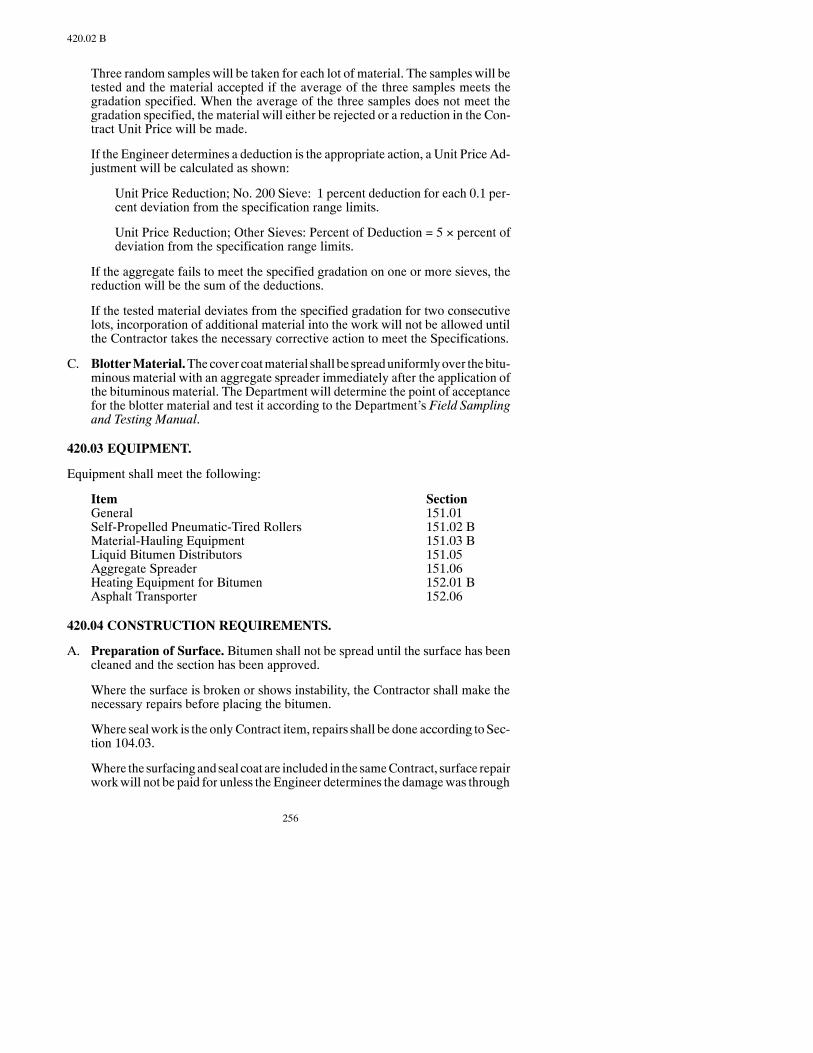
256
420.02 B
Three random samples will be taken for each lot of material. The samples will betested and the material accepted if the average of the three samples meets thegradation specified. When the average of the three samples does not meet thegradation specified, the material will either be rejected or a reduction in the Con-tract Unit Price will be made.
If the Engineer determines a deduction is the appropriate action, a Unit Price Ad-justment will be calculated as shown:
Unit Price Reduction; No. 200 Sieve: 1 percent deduction for each 0.1 per-cent deviation from the specification range limits.
Unit Price Reduction; Other Sieves: Percent of Deduction = 5 × percent ofdeviation from the specification range limits.
If the aggregate fails to meet the specified gradation on one or more sieves, thereduction will be the sum of the deductions.
If the tested material deviates from the specified gradation for two consecutivelots, incorporation of additional material into the work will not be allowed untilthe Contractor takes the necessary corrective action to meet the Specifications.
C. BlotterMaterial.Thecover coatmaterial shall be spreaduniformlyover thebitu-minous material with an aggregate spreader immediately after the application ofthe bituminous material. The Department will determine the point of acceptancefor the blotter material and test it according to the Department’s Field Samplingand Testing Manual.
420.03 EQUIPMENT.
Equipment shall meet the following:
Item SectionGeneral 151.01Self-Propelled Pneumatic-Tired Rollers 151.02 BMaterial-Hauling Equipment 151.03 BLiquid Bitumen Distributors 151.05Aggregate Spreader 151.06Heating Equipment for Bitumen 152.01 BAsphalt Transporter 152.06
420.04 CONSTRUCTION REQUIREMENTS.
A. Preparation of Surface. Bitumen shall not be spread until the surface has beencleaned and the section has been approved.
Where the surface is broken or shows instability, the Contractor shall make thenecessary repairs before placing the bitumen.
Where sealwork is the onlyContract item, repairs shall be done according toSec-tion 104.03.
Where the surfacingandseal coat are included in the sameContract, surface repairworkwill not be paid for unless the Engineer determines the damagewas through

257
420.04 C
no fault of theContractor, inwhich case repairs shall be done according toSection104.03.
B. Application of Bitumen.Bitumen shall be applied with a pressure distributor ina uniform, continuous spread. The quantity of bitumen to be used per square yardshall be as directed by the Engineer. Any skipped areas or deficiencies shall becorrected. Junctions of spreads shall be carefully made to assure a smooth ridingsurface and complete cover.
Streaking of the bitumen on the road surface will not be allowed. Streaking is thenon-uniform application of bitumen leaving alternating lean and heavy narrowbands of bitumen. If theEngineer determines that streaking is occurring, theCon-tractor shall cease operationsuntil theEngineer is satisfied that streakinghasbeeneliminated.
The surfaces of all structures and other appurtenances shall be protected againstsplattering. If splattering occurs, it shall be removed to the satisfaction of the En-gineer at the Contractor’s expense.
When traffic is maintained, the bitumen shall be applied in passes of approxi-mately one-half the width of the completed surface. If the width of the surfacemakes such application impracticable, the bitumen may be applied in more thantwo passes.
The bitumen shall be applied so that, when covered, the overlaps caused by suc-cessive applications will not result in ridges or depressions at the transverse orlongitudinal joints. The joints shall be smooth and consistent with the adjacentcompleted surface treatment.
To prevent lapping at transverse junctions, the bitumen spray shall be promptlyshut off at the end of the application. Before continuing the application, buildingpaper or metal sheets shall be spread a sufficient distance back from the joint onthe cover aggregate so the sprayers are operating at full forcewhen the distributorhas attained the predetermined speed upon reaching the uncovered surface. Allpaper or metal sheets used shall be removed.
C. Cover CoatMaterial Application. The cover coat material shall be spread uni-formlyover thebituminousmaterialwith anaggregate spreader. Small areas inac-cessible to the aggregate spreader may be covered by hand or other approvedmethods.
The quantities of cover coatmaterial shown are based on estimated rates. The ac-tual coverage rates will be determined by the Engineer.
Immediately after the cover coat material is spread, any deficient areas shall becoveredby additional cover coatmaterial or blottermaterial as directedby theEn-gineer.
Rolling shall begin immediately behind the spreader and shall continue until aminimum of four complete coverages are obtained. The speed of the roller shallnot exceed 7MPHon the initial coverage.A self-propelled pneumatic-tired rollershall be used to complete the rolling.
The loose cover coat material shall be lightly broomed off during the cool periodof early morning within 36 to 48 hours from the time of application. The broom
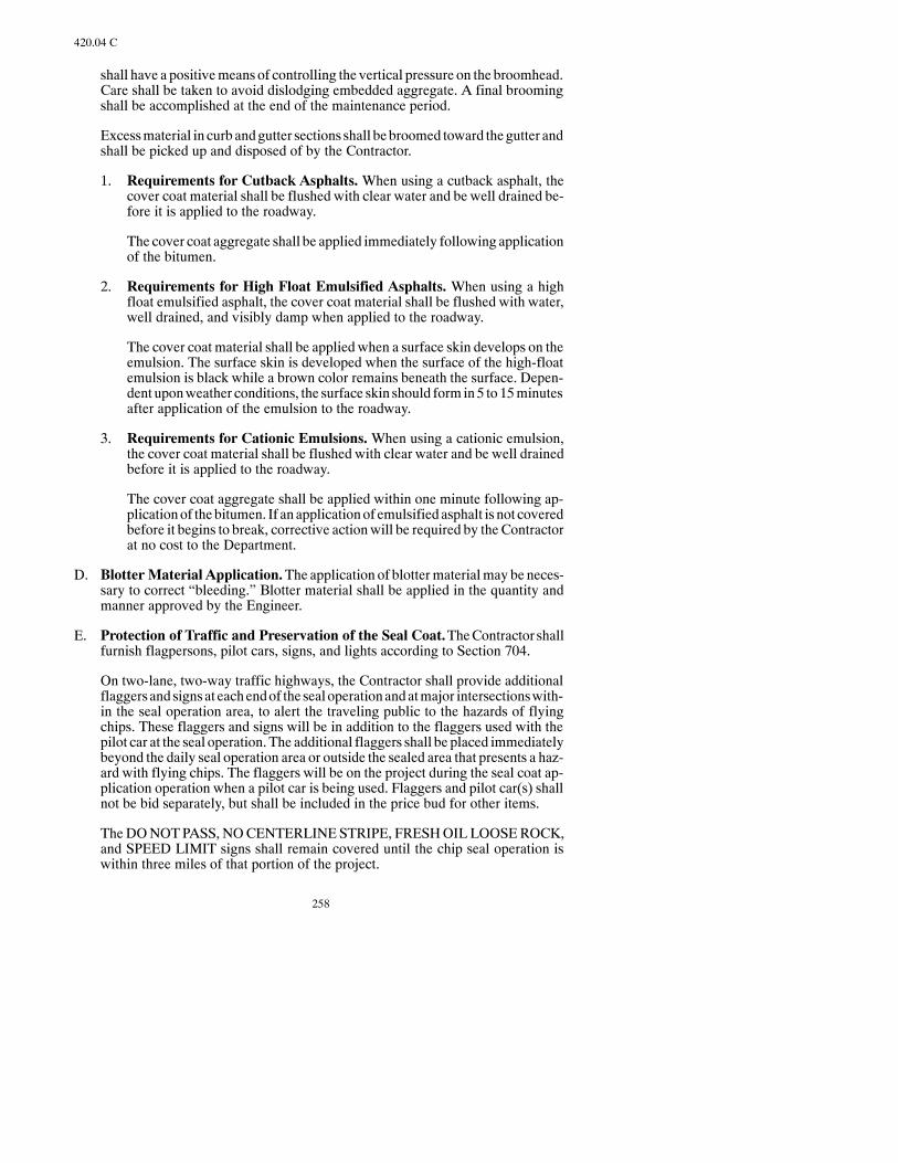
258
420.04 C
shall have a positivemeans of controlling the vertical pressure on the broomhead.Care shall be taken to avoid dislodging embedded aggregate. A final broomingshall be accomplished at the end of the maintenance period.
Excessmaterial in curb andgutter sections shall bebroomed toward the gutter andshall be picked up and disposed of by the Contractor.
1. Requirements for Cutback Asphalts.When using a cutback asphalt, thecover coat material shall be flushed with clear water and be well drained be-fore it is applied to the roadway.
The cover coat aggregate shall be applied immediately following applicationof the bitumen.
2. Requirements for High Float Emulsified Asphalts. When using a highfloat emulsified asphalt, the cover coat material shall be flushed with water,well drained, and visibly damp when applied to the roadway.
The cover coat material shall be applied when a surface skin develops on theemulsion. The surface skin is developed when the surface of the high-floatemulsion is black while a brown color remains beneath the surface. Depen-dent uponweather conditions, the surface skin should form in5 to15minutesafter application of the emulsion to the roadway.
3. Requirements for Cationic Emulsions.When using a cationic emulsion,the cover coat material shall be flushed with clear water and be well drainedbefore it is applied to the roadway.
The cover coat aggregate shall be applied within one minute following ap-plicationof thebitumen. If an applicationof emulsified asphalt is not coveredbefore it begins to break, corrective actionwill be required by the Contractorat no cost to the Department.
D. Blotter Material Application.The application of blottermaterialmay be neces-sary to correct “bleeding.” Blotter material shall be applied in the quantity andmanner approved by the Engineer.
E. Protection of Traffic and Preservation of the Seal Coat.TheContractor shallfurnish flagpersons, pilot cars, signs, and lights according to Section 704.
On two-lane, two-way traffic highways, the Contractor shall provide additionalflaggersandsignsat eachendof the seal operationandatmajor intersectionswith-in the seal operation area, to alert the traveling public to the hazards of flyingchips. These flaggers and signs will be in addition to the flaggers used with thepilot car at the seal operation. The additional flaggers shall be placed immediatelybeyond the daily seal operation area or outside the sealed area that presents a haz-ard with flying chips. The flaggers will be on the project during the seal coat ap-plication operation when a pilot car is being used. Flaggers and pilot car(s) shallnot be bid separately, but shall be included in the price bud for other items.
TheDONOTPASS, NOCENTERLINESTRIPE, FRESHOIL LOOSEROCK,and SPEED LIMIT signs shall remain covered until the chip seal operation iswithin three miles of that portion of the project.
259
420.05 B
On four-lane highways the additional flaggers will not be required.
The seal coat shall bemaintained by the Contractor during the seal coat operationandmaintenance shall continue for an additional five calendar days after comple-tion of the seal coat work. The Contractor shall repair the seal coat within twohours of the time the need for such repairs are noted.
Maintenance of the seal coat may require application of blotter sand to preventbleeding, application of more bitumen, application of more seal aggregate, andadditional rolling. The blotter sand shall be applied with a mechanical spreadersuch as a tailgate sander or other approved device. The sweeping of loose covercoatmaterial from the shoulder onto the new sealed surfacewill not be permitted.
As soon as practicable after sealing and no later than five days after the seal hasbeen applied, all excess cover coat material shall be swept and removed from theentire surface as directed by the Engineer.
F. Limitations.
1. Weather.Bitumenshall notbeappliedonawet surfaceorwhenweather con-ditionswould prevent the proper construction of the seal coat. Sealworkwillnot be permitted when the pavement temperature is below 70°F.
Seal work shall not be started after September 1.
2. Operational. Prior to the application of the seal coat, each type of surfacelisted below shall be allowed a curing period after laydown and compactionhas been completed as follows:
a. Prime coat ---- 4 days.
b. SC, MC or RC Pavements ---- 15 days.
c. Asphalt Cement Pavements ---- 7 days.
d. Emulsion Pavements ---- 15 days.
These curing periodsmay be increased or decreased as directed by the Engi-neer.
Sealingwork shall not be permitted at night. Unless otherwise authorized bythe Engineer, the work shall be scheduled so that the last application of theday shall be placed in time for the bitumen to cure sufficiently to allow instal-lation of the short-termpavementmarking before sunset, as specified in Sec-tion 762.04 D.1.
420.05 METHOD OF MEASUREMENT.
A. Bitumen. Bitumen will be measured by the Ton or Gallon.
B. Cover Coat Material and Blotter Material. Cover Coat Material and BlotterMaterial will be measured by the Ton or Cubic Yard or Square Yard.

260
420.06
420.06 BASIS OF PAYMENT.
Payment will be made at the Contract Unit Price for the following:
Pay Item Pay Unit—Liquid Asphalt Ton or Gallon—Emulsified Asphalt Ton or GallonCover Coat Material Class— Ton or Cubic Yard
or Square YardBlotter Material Ton or Cubic Yard
or Square Yard
This payment will be full compensation for all labor, equipment, andmaterials neces-sary to complete thework. The cost of flushing the cover coatmaterialwithwater shallbe included in the cost of the Contract Unit Price Bid for cover coat material.
If the bid item“BlotterMaterial” is not included as a pay item in theContract, paymentwill be made at the rate specified in the Price Schedule (PS-1) in the Proposal.

261
SECTION 500RIGID PAVEMENT

262

263
SECTION 550PORTLAND CEMENT CONCRETE PAVEMENT
550.01 DESCRIPTION
550.02 MATERIALSA. GeneralB. Portland Cement ConcreteC. Joint Materials
1. Concrete Joint Sealer2. Fillers and Sealant
550.03 EQUIPMENT
550.04 CONSTRUCTION REQUIREMENTSA. GeneralB. Fine Grading and Conditioning RoadbedC. Handling and Storing MaterialsD. BatchingE. Measuring and Dispensing AdmixturesF. Mixing and Transporting ConcreteG. Placing and Spreading Concrete
1. General2. Formed Paving3. Slip Form Paving
a. Line and Gradeb. Placing Concrete
H. Placing ReinforcementI. Joints
1. General2. Transverse Contraction Joints3. Transverse Expansion Joints4. Transverse Construction Joints5. Tie Bars and Longitudinal Joints
J. Finishing Concrete1. Sequence2. Use of Water3. Screeding
a. Slip Form Pavingb. Other Paving Methods
4. Floating5. Straightedging6. Final Surface Finish7. Imprinting Pavement
K. Curing Concrete1. General2. Wetted Fabric Cure3. Liquid Membrane Cure
a. Generalb. Application
L. Removing FormsM. Sealing Joints and Cracks
1. General2. Hot Poured Elastic Type Joint Seal Installation3. Silicone Joint Sealant Installation

264
a. Cleaning Jointsb. Backer Rod Installationc. Joint Sealer Application
4. Preformed Elastomeric Compression Joint SealN. Protection of PavementO. Opening to TrafficP. Tolerance in Surface and Ride Quality
1. Surface Tolerance2. Riding Quality3. Grinding4. Pay Adjustment
Q. Tolerance in Pavement Thickness and Reinforcing Steel1. General2. Pavement Units3. Determination of Pavement Thickness4. Reinforcing Steel Placement
R. Operational Limits
550.05 METHOD OF MEASUREMENT
550.06 BASIS OF PAYMENT
SECTION 560RECYCLED PORTLAND CEMENT
CONCRETE PAVEMENT
560.01 DESCRIPTION
560.02 MATERIALS
560.03 EQUIPMENT
560.04 CONSTRUCTION REQUIREMENTS
A. Prepare Stockpile SitesB. StockpilingC. Removing Concrete PavementD. Existing Reinforcing SteelE. Processing Salvaged ConcreteF. MixingG. PlacingH. Pavement Surface Riding QualityI. Determination of Pavement Thickness
560.05 METHOD OF MEASUREMENT
560.06 BASIS OF PAYMENT
265
SECTION 570PORTLAND CEMENT
CONCRETE PAVEMENT REPAIR
570.01 DESCRIPTION
570.02 MATERIALSA. GeneralB. Portland Cement Concrete for RepairsC. Joint Materials
1. Concrete Joint Sealer2. Fillers and Sealant
D. Dowel Bar Retrofit1. Curing Compound2. Dowel Bars3. Caulk4. Foam Core Board5. Patching Material6. Chairs7. Concrete Mix Design
E. Joint Stitching1. Epoxy2. Tie Bars
570.03 EQUIPMENT
570.04 CONSTRUCTION REQUIREMENTSA. General
1. Restoring the Subgrade2. Forms for PCC Repairs3. Damaged Areas4. Reinforcing Steel5. Spall Repair6. Repair Size and Longitudinal Joint Treatment7. Placing Portland Cement Concrete8. Longitudinal Joint Sealing
B. Non-Reinforced Jointed PCC Pavement Repairs1. Existing Non-Reinforced, Jointed PCC Pavement Removal2. Work Sequence3. Bars for Transverse Joint at Full-Depth Repairs (Load Transfer)4. Transverse Joint Sealing at Full-Depth Repairs
C. Dowel Bar Retrofit1. Sawing2. Jack Hammers3. Cleaning4. Dowel Bar Chair Placement5. Joint Caulking6. Dowel Bar Placement7. Mixing Patch Material8. Existing Concrete Surface Preparation9. Placing Patch Mix10. Curing11. Spall Repairs12. Opening to Traffic13. Grinding

266
D. Joint Stitching1. Drilling2. Cleaning3. Epoxy4. Tie Bars
E. Grinding1. Equipment2. Construction Requirements
a. Grinding Depthb. Grinding Directionc. Textured. Transitionse. Slopef. Clean-Up
3. Ride Qualitya. Equipmentb. Calibrationc. Operationd. Evaluation
4. Jointsa. One-Half Inch Transverse PCC Joint Cleaning and Sealingb. Longitudinal PCC Joint Cleaning and Sealing
F. Continuously Reinforced PCC Pavement Repairs1. Existing Concrete Removal2. 24-Foot-Wide, Full-Depth Repairs
570.05 METHOD OF MEASUREMENT
A. Spall RepairB. Longitudinal PCC Joint Cleaning and SealingC. Full-Depth Repair ItemsD. Dowel BarsE. One-Half Inch Transverse PCC Joint Cleaning and SealingF. Inch Concrete Pavement Repair (Full-Depth -- Doweled)G. SawcutsH. Full-Depth RepairsI. Dowel Bar RetrofitJ. Joint StitchingK. GrindingL. One-Half Inch Transverse PCC Joint Cleaning and SealingM. Longitudinal PCC Joint Cleaning and SealingN. Full-Depth Repairs -- End PreparationO. Full-Depth Repair End Prep-Mech SpliceP. Full-Depth Continuous Concrete Repair
570.06 BASIS OF PAYMENT SUMMARY

267
550.03
SECTION 550PORTLAND CEMENT CONCRETE PAVEMENT
550.01 DESCRIPTION.
Thiswork consists of constructing a pavement composed of PortlandCementConcrete,with or without reinforcements, as specified, on a prepared subgrade or base course.
550.02 MATERIALS.
A. General.Materials shall meet the following:
Item SectionGrouts and Mortar 806Reinforcing Steel 836Dowel Bars 836
B. Portland Cement Concrete. Class AE Portland Cement Concrete pavementshall consist of virgin aggregate,water, an air entrained agent, andType I, IA, or IIPortland Cement.
Material shall meet the requirements of Section 802.
C. Joint Materials.
1. Concrete Joint Sealer.The joint sealer shall be as shownon thePlansunlessan alternate type is approved by the Engineer before use.
2. Fillers and Sealant.Materials shall meet the following:
Item SectionHot-Poured Joint Sealant 826.02Silicone Joint Sealant 826.02 BBacker Rod 826.02 B.1Preformed Expansion Joint Filler 826.02 CPreformed Expansion Joint Fillers 826.02 D(Bituminous type)
Preformed Elastomeric Compression Joint Seal 826.02 G
550.03 EQUIPMENT.
Equipment shall meet the following:
Item SectionGeneral 151.01P.C.C. Equipment 153

268
550.04
550.04 CONSTRUCTION REQUIREMENTS.
A. General. If a previously constructed lane of pavement is used as a side-form tosupport concrete finishing equipment, the pavement shall have been in place for72 hours except when the ambient temperature is less than 40°F., then the pave-ment shall have reached a compressive strength of at least 3,000 psi before con-crete shall be placedagainst it. If thepreviously constructedpavement is damagedduring fine grading and paving operations, work shall be suspended until thecause of damage is corrected. Damaged pavement shall be replaced or satisfacto-rily repaired at the Contractor’s expense.
B. Fine Grading and Conditioning Roadbed. Hauling and mixing equipmentshall not operate on the finished grade except when the operation of this equip-ment off the finished grade is impractical due to restricted access.When theEngi-neer permits equipment to beoperated on the finishedgrade, satisfactory arrange-ments shall be made for protection or repair of the roadbed. During concreteplacement the roadbed shall be in a smooth, compacted condition, and shall besufficiently moist to prevent absorption of water from the concrete. Roadbedsshall be kept moist without forming of mud or pools of water.
Maintenance, repair, and restoration of the subgrade and base course before plac-ing the concrete pavement shall be at the Contractor’s expense.
C. Handling and Storing Materials. Materials for concrete shall be handled andstored according to Section 802.04 A.
D. Batching.Batching of concretematerials shall be according to Section 802.04B.Aggregates and bulk cement shall be proportioned by automatic batching equip-ment meeting Section 153.01 B.
E. Measuring and Dispensing Admixtures. Any admixture approved for use inthe concrete mixture shall be measured and dispensed according to Section802.04 C.
F. Mixing and Transporting Concrete. The concrete shall be mixed and trans-ported according to Section 802.04Dand the additional requirements of this Sec-tion.
Mixers andhauling equipment shall not be operated on the roadbed except as pro-vided in Section 550.04 B.
Mixersandhaulingequipment shall notbeoperatedonanewly-constructedpave-ment except as permittedby theEngineer and according toSection550.04O.Anyfresh concrete spilled on the existing slab shall be promptly removed.
G. Placing and Spreading Concrete.
1. General. The concrete shall be deposited on the roadbed so segregation andunnecessary rehandling is avoided. Placement shall be continuous betweenall transverse joints. If concrete placement is temporarily interrupted, the un-finished face of the concrete shall be kept moist by spraying a mist over theconcrete or applying wet burlap and protected against drying by covering
269
550.04 G.3.a
with burlap or plastic sheeting.When placement operations are resumed, theconcrete shall be broken down and thoroughly consolidated with the freshconcrete. If the elapsed time between placement of successive batches orloads of concrete exceeds 45minutes, a transverse construction joint shall beinstalled.
Concrete shall be deposited and spread so joint installations and reinforce-ment are not damaged or displaced.
Spreading and initial strike-off shall be performed by a mechanical spreadermeeting Section 153.07. Concrete shall be spread uniformly across the fullwidth of the slab being paved, and shall be struck off at a height which pro-vides a proper quantity of concrete for subsequent paving operations. Othermethods of spreading may be approved by the Engineer where use of a me-chanical spreader is not feasible.
Immediately after the concrete is spread and struck off, it shall be thoroughlyconsolidated by fullwidth vibratory equipmentmeetingSection 153.08.Ap-provedportable vibratory equipmentmaybeusedwhereworkdimensionsorfeatures do not permit use of full-width vibratory equipment.
Over vibration, evidenced by segregation of material and excessive surfacemortar, will not be permitted and vibration in excess of 4 seconds in any onespotwill notbeallowed.Segregatedarea shall be removedand replacedat theContractor’s expense.
Continuous rumble strips shall bemilled inbothpavedconcrete shoulders, asshown in the Plans. Rumble strips shall not be installed in the ramp area adja-cent to themainline.TheContractor shall establish rumble strip locationsandspacing.
Communications shall be provided and maintained by the Contractor be-tween the proportioning plant and the paving operation.
2. Formed Paving. The roadbed shall be prepared so the forms are adequatelyand uniformly supported for their entire length at the established grade.
Side forms shall meet Section 153.04. The form sections shall be securelystaked and free from play or movement in any direction.
After staking, the grade shall be thoroughly tampedmechanically at both theinside and outside edges of the base of the forms.
When in final position, the forms shall not deviate at any point by more than1/8 inch from the established grade or by more than 1/2 inch from the estab-lished alignment. Forms shall be set sufficiently in advance of placing con-crete to provide time for the Engineer to check line and grade. The length offorms in place shall be equal to the anticipated linear feet of pavement to beplaced in 2hours. Formswhich aredisturbedor showevidenceof anunstablefoundation shall be reset.
3. Slip Form Paving.
a. Line and Grade. The Department will set appropriate stakes for estab-lishing the finished line and grade of the pavement. TheContractor shall

270
550.04 G.3.a
erect and maintain the necessary taut lines for operating the automaticequipment and preserve the line and grade stakes set until the pavementis placed.
b. Placing Concrete.When placing concrete pavement on a divided high-way, the inside mainline shoulder and the two driving lanes shall beplaced in one continuous operation. Concrete shall be uniformly placedat a rate and consistency that produces a dense and homogeneous pave-ment with a minimum amount of manual finishing.
The slip form paver shall be operated in a continuous forward move-ment.All concretemixing,delivering,placing, andspreadingoperationsshall becoordinated toprovide acontinuousanduniformforwardmove-ment without stopping and restarting the paver.
During paving operations, a constant and uniformhead of concrete shallbe maintained in front of the paver. This head shall be maintained at adepth within the range of 0.5 to 2 times the depth of the finished slab.
(1) Consolidation – Vibrator Operation. The slip-form pavingequipment shall consolidate the fullwidth anddepthof concrete in asingle pass, using an approved internal or surface vibrator. Internalvibrators shall penetrate into the concrete pavement slab tomid slabor as deep aspossiblewhile passing above any reinforcing steel. Anoperating position-locking device shall be provided so that no partof the vibrating unit can be lowered to the extent that it will come incontact with reinforcing steel or tie bars while paving. Internal vi-brators shall be operatedwithin a frequency range of 4,000 to 8,000vibrations per minute. The Engineer may authorize the minimumvibration frequency lowered to 3,500 vibrations perminute for par-ticular sections of paving such as super elevations. However, in nocase shall the frequency exceed 8,000 vibrations per minute. Sur-face vibrators shall be operatedwithin a frequency rangeof 3,500 to6,000 vibrations per minute. Vibrators shall not be operated in amanner to cause segregation of the mix ingredients (either a down-ward displacement of large aggregate particles or an accumulationof laitance on the surface of the concrete). Mix-segregation avoid-ance may require a reduction in vibrator frequency when forwardmotion of the paver is reduced.
If a vibrator fails to operatewithin the specifications, theContractorshall repair or change the vibrator before the paving begins the fol-lowing day or begins the same day, if the continuous paving isstopped at a header or at the end of a session.
If two adjacent vibrators fail to operate within Specifications, thepaving operation shall stop and repairs made or vibrators replaced.
Vibrators shall be stoppedwhenever forwardmotion of the paver isstopped.
A vibrator monitor shall be operated to record, at a minimum, theclock time, station location, paver track speed, and operating fre-

271
550.04 I.1
quency of individual vibrators. Recordings shall bemade after each25 feet of paving or after each five minutes of time, whichever oc-curs first. An electronic and printed record of the data shall be pro-vided to theEngineer, daily. TheEngineermaydetermine thatmorefrequent submission is necessary, particularly if equipment mal-functions occur. Either the printed or electronic records (or both)shall be produced in their final form prior to the records being re-moved from the paver (i.e. the Contractor shall either produce aprintout or diskette from the recording device, on the paver andpresent this record to theEngineer, in the field). If only one record isproduced at the paver, the othermay be produced in an office.How-ever, the first record shall be presented to the Engineer prior to anyof the data entering an office environment. The electronic recordshall be acommaor spacesdelimited text file, adequate for insertioninto a computerized spreadsheet software package. Additionally,theContractor shall, once perweek (or as directed by theEngineer),provide a written explanation of vibrator setting changes, out-of-tolerance vibratory operations, and monitoring-device malfunc-tions.
If the electronic monitoring device fails to operate properly, the vi-brators shall immediately be checkedmanually. If the vibrators arefunctioning properly, pavingmay continue, but theContractor shallmakeall efforts to correct themalfunction in a reasonable amountoftime. If the recording device fails to operate, paving may continuebut theContractor shall correct themalfunctionwithin three pavingdays. TheEngineermay allow additional time if, in the sole opinionof theEngineer, circumstances are beyond theContractor’s control.
H. Placing Reinforcement. Reinforcement, when specified, shall be installed ac-cording to details shownon thePlans. The reinforcing steel shall be free fromdirt,oil, paint, grease, mill scale, and loose or thick rust which could impair the bondbetween the steel and concrete.
The reinforcement shall be positioned on approved supports in advance of theconcrete placement or inserted in the plastic concrete by an approvedmechanicaldevice.
TheContractor shall verify the placement of reinforcement in the plastic concretepavement. At minimum, the reinforcement location will be verified at the start ofpaving each day and at a frequency of every 500 feet during normal paving.
Onprojectswith over 20,000SYof concrete paving, the location of the reinforce-ment shall be verified by the use of amicro covermeter. TheContractor shall pro-vide the micro covermeter and, at the request of the Engineer, allow the Depart-ment personnel to confirm bar locations with the micro covermeter.
If the reinforcement does not meet the requirements and tolerances specified forthe placement of the reinforcement, corrective action shall be taken immediatelyand performed at the Contractor’s expense.
I. Joints.
1. General. Joints in concrete pavement shall be of the design specified andshall be constructed at the spacings and locations shown. The ramp joints be-

272
550.04 I.1
yond the ramp taper shall have the same spacing sequence as the mainline.The Contractor shall establish joint locations.
2. Transverse Contraction Joints. The contraction joints shall consist ofweakenedplanes createdby sawingonmain line and shoulders, and by eithersawing, inserting preformed inserts, or forminggrooves in the pavement sur-face on small areas or tapers. The location of grooves to be formed or sawedshall be clearly and accurately marked on the plastic concrete surface by theContractor.When specified, the contraction joints shall include a load trans-fer device.
Sawed contraction joints shall be cut to the required dimensions with equip-ment meeting Section 153.12. The time and sequence of sawing shall be ad-justed so all joints are cut before uncontrolled cracking occurs, and to permitsawing without excessive raveling. Joints shall be sawed within 24 hours toprevent uncontrolled cracking. Uncontrolled cracking that occurs shall berouted, cleaned and sealed according to Section 550.04 M.3 at the Contrac-tor’s expense. Immediately after sawing, the joint shall be flushedwithwaterunder sufficient pressure to remove residue left by the sawingoperation. If anuncontrolled crack occurswithin 5 feet of any proposed joint location beforeor during sawing, the joint shall be omitted and sawing of the joint discontin-ued. Any joint sawedwithin 5 feet of an uncontrolled crack shall be repairedat theContractor’s expense.Whensawing isperformedbefore removingsideforms, the initial saw cut will extend to within 1/2 inch or less of the sideforms. If the forms have been removed, the saw cut will be extended to theedgesof the slab.Anycuringmedia removedduring sawing shall be immedi-ately replaced.
Before installing silicone sealant or preformed elastomeric compressionjoint seal, all joint grooves shall be inspected and spalls which are greaterthan 1/4 inch in depth shall be repaired by patching with an approved epoxymortar meeting Section 806. Loose concrete shall be removed from thespalled area and the area shall be thoroughly cleaned. Heavy sheets of poly-ethylene, polyvinyl chloride, or other suitablematerial which do not bond tothe epoxy shall be inserted in the joint groove to form the faces of the spalledpatch. After cleaning, the spalled surface shall be primed with a brush appli-cationof epoxybinder, andanepoxymortar of trowelingconsistency shall beplaced in the spalled area and finished as the original pavement surface. Theepoxy binder components shall bemixed in proportions and bymethods rec-ommendedby themanufacturer.After the epoxybinder is thoroughlymixed,dry concrete sand shall beblended into themixture togive anepoxymortar oftrowelable consistency. Patchingof spalls shall bedoneonlywhen the air andpavement temperature is above 40°F. Dry concrete sand shall be sprinkledonto the fresh epoxy mortar surface to eliminate any gloss. After the epoxymortar has cured, the inserts shall be removed.
Formed contraction joints shall be constructed by installing an approvedpreformed insert into the plastic concrete before final surface finishing. Theinserts shall bevibrated intoplaceor installed in agroove formedbyavibratingcutter bar. The inserts top edges shall be flushwith the concrete surface. Anyvoids, depressions, or ridges of concrete caused by installing inserts shall befilled or removed by hand-finishingmethods, and the surface across the jointshall be straight-edged according to Section 550.04 J.5. The groove formed

273
550.04 I.3
by the inserts shall be perpendicular to the pavement surface, true to the re-quired alignment, and continuous along the full length of the joint. Inserts,except those designed to remain, shall be removed without damage to adja-cent concrete.
When specified for use with the transverse contraction joint the dowel barsshall be held in the specified position parallel to the slab surface and to thecenterline within a tolerance of 1/8 inch per foot vertically and horizontally.The dowel bar assembly shall be an approved metal supporting device se-curely staked to the roadbed and shall hold the dowel bars at the correct spac-ing, alignment and elevation. The position of the load transfer units shall beaccurately marked with steel pins, or other precise methods, to locate thetransverse joint over the center of the dowels.After the dowel bar assembly isstaked to the roadbed and the dowel bars are held firmly in place, the assem-bly ties runningparallel to the dowel bars shall not be cut, but remain inplace.
Dowel baskets shall be placed ahead of the paving operation with sufficientdistance to allow adequate time to be properly inspected.
A uniform coat of Tectyl 506, NLGI Grade #2 multipurpose lithium grease,an approved equal, shall be applied by the manufacturer to the full length ofthe dowel bars to act as a release agent.
3. Transverse Expansion Joints. The expansion joints shall be formed by in-stalling preformed expansion joint filler at designated locations.
Dowel bars shall be installed in the expansion joint to act as a load transferdevice. The dowels shall be held in the specified position parallel to the slabsurface and centerline by a metal supporting device securely staked to theroadbed and shall hold the dowel bars at the correct spacing, alignment, andelevation. The dowel bars shall be placed within a tolerance of 1/8 inch perfoot vertically and horizontally. The “free” half of each dowel shall be coatedwith a thin uniform coat of Tectyl 506, NLGIGrade #2multipurpose lithiumgrease, or an approvedequal, as the release agent, andcoveredwith ametal orplastic dowel capor sleeve. The capsor sleeves shall fit the dowel bars tightlyand the closed end shall bewatertight.After the dowel bar assembly is stakedto the roadbed and the dowel bars are held firmly in place, the assembly tiesrunning parallel to the dowel bars shall not be removed but shall remain inplace to maintain the proper alignment of the dowel bars.
Preformed expansion joint filler shall be of the dimensions shown on thePlans and shall extendacross the fullwidth anddepthof the slab at each trans-verse expansion joint. Filler shall be furnished in individual sectionshavingalength equal to the pavement slab width being poured. Filler shall be accu-rately prepunched to fit snugly around the dowels.
The expansion joint assembly shall be securely staked to the subgrade. Un-less the preformed filler is adequately supported by a load transfer assemblyor other device designed to remain in the pavement, a suitable installing baror header shall be used to support filler during placement and finishing of ad-jacent concrete. Filler shall be installed perpendicular to the pavement sur-face and true to the designated line of the joint.Wheremore than one sectionof filler is permitted, abutting ends of individual sections of filler shall be

274
550.04 I.3
neatly and securely jointed without any gap or offset between sections. Thebottom edge of filler shall extend to or slightly below the bottomof the pave-ment. The top edge of filler shall be approximately 1/2 inch below the pave-ment surface. During placement and finishing of adjacent concrete, the topedge of filler shall be protected by a removable channel cap having flangesnot less than 1-1/2 inches deep. An aluminum channel cap shall not be used.
Installation of the expansion joint assembly shall be approved before anyconcrete is placed against the joint. Equal pressure shall be maintainedagainst both sides of the preformed filler as the concrete is placed, and an ap-proved internal vibrator shall be used to consolidate the concrete on each sideof the joint. After the concrete has been placed and finished, the protectivechannel cap shall be removed, the top edge of the filler shall be exposed overits full width and length, and the concrete on each side of the joint shall beedged to the specified radius. After the side forms have been removed, anyconcrete which flowed around the ends of the joint shall be removed to ex-pose the full thickness and height of the filler.
The expansion joint shall be sealedwith a lowmodulus silicone sealantmeet-ing Section 826.02 B. All materials and installationmethods shall meet Sec-tion 550.04 M.3.
At structures projecting through, into, or against the pavement, expansionjoints of a preformed or poured type shall be constructed as specified.
4. Transverse Construction Joints. A transverse construction joint shall beinstalledat the endof eachday’spour andwhenever theelapsed timebetweenplacement of successive batches or loads of concrete exceeds 45 minutes.Transverse construction joints shall be installed halfwaybetween 2normallyspaced transverse joints.
The transverse construction joint shall be formed by installing an approveddowel splicer bar basket assembly. The dowel splicer bar assembly shall holdthe dowel splicer bars parallel to the centerline and slab surface. The dowelsplicer bars shall be placed within a tolerance of 1/8 inch per foot verticallyand horizontally.
The dowel splicer basket assembly shall be staked perpendicular to the cen-terline and marked. The Contractor shall pave over the assembly far enoughto maintain the elevation of the top of the slab. A full depth saw cut shall bemade to expose the dowel splicer bar, the excess concrete shall be disposedofand the threaded dowel extension bar shall be installed.
After the adjacent slab is placed the construction joint shall be sawed andsealed as specified.
On shoulders or urban projects where the Engineer determines it is not feasi-ble to install a dowel splicer bar basket assembly the transverse constructionjoint shall be formed by installing an approved header shaped to conform tothe cross-section of the slab being placed. The header shall be rigid and se-cured to prevent bulging or displacement while adjacent concrete is beingplaced and finished. The face of the header in contact with the concrete shallbe perpendicular to the pavement surface and shall be at right angles to the

275
550.04 J.1
pavement centerline.A two-pieceor other approvedheader shall bedesignedto accommodate proper placement of any dowel bars or reinforcement ex-tending across the joint and to allow removalwithout damage to the concrete.
The concrete adjacent to the header shall be thoroughly consolidated by aninternal vibrator or other approved methods. Segregated or improperly con-solidated concrete shall be removed. After the pavement has been finished,the surface adjacent to the header shall be edged to the specified radius.
5. TieBars andLongitudinal Joints.Tie bars or tie bar baskes shall be held inthe specifiedpositionparallel to the slab surfaceandperpendicular to thecen-terline by a supporting device securely staked to the roadbed and shall holdthe tie bars or tie bar baskets at the correct spacing, alignment, elevation , andwithin tolerance. Tie bars will not require support if inserted into the side ofthe pavement during slip form paving of the longitudinal construction jointoperation. Tie bars or tie bar baskets shall be placed so that theyare notwithin15 inches of the intersection of the longitudinal join and transverse joint.
The tie bars final position shall be within the following tolerances:
-- Vertical Placement ±1 inch
-- Transverse Placement ±3 inches
The location of the tie bars under the longitudinal joints will be randomlychecked twice a day to assure that their location is within the allowabletolerances. Failure to acquire the correct tie bar location shall requiresupporting the tie bars on chairs.
a. Longitudinal Weakened-Plane Joints. Planes of weakness for longi-tudinal joints shall be created by sawing grooves in the pavement sur-face.Grooves shall be sawed tomeet dimensions shownandshall be trueto the required alignment of the joint.
Equipment for sawing longitudinal joints shall meet Section 153.12. Assawing progresses, the joint shall be immediately flushedwithwater un-der sufficient pressure to remove residue left by the sawing operation. Ifsawing is performedbefore expiration of the required curing period, anycuring media removed shall be immediately replaced after flushing.Sawing of longitudinal joints shall be completedwithin seven days afterconcrete placement.
b. Longitudinal Construction Joints.The longitudinal joint betweenad-joining, separatelyconstructed lanesof pavement shall be constructedasshownon thePlans.Tie bars across longitudinal construction joints shallbe at the locations, spacing, and depth shown. Tie bars may be bent atright angles against the form of the first lane constructed and straight-ened into final positionbefore the concrete of the adjacent lane is placed.The bars may be inserted through small, accurately positioned holes inthe side forms; approved two-piece connectors may also be used.
J. Finishing Concrete.
1. Sequence.After concrete has been placed, spread, and vibrated according toSection 550.04 G, the sequence of finishing operations shall be screeding,

276
550.04 J.1
floating if required, straight edging, final surface finishing, and edging atforms and joints.
2. Use of Water.Whenweather conditions cause rapid drying of the pavementsurface a fine mist or fog spray shall be applied to the concrete surface forinterim curing. Use of brushes to apply water and use of water to facilitatefinishing will not be permitted.
3. Screeding.
a. Slip Form Paving.When the concrete is placed with a slip form paver,the screeding shall be done by the paver.
b. Other Paving Methods.Machinemethods shall be employed to screedand consolidate the concrete, except where the Engineer determines theuse of machine methods is not feasible. If the screedingmachine breaksdown the concrete that was mixed at the time of breakdown, may bemanually screeded provided the final product meets specified require-ments. If the finished work is unsatisfactory, it shall be repaired or re-moved and replaced at the Contractor’s expense.
Transverse screeding machines meeting Section 153.09 shall be oper-ated over each area of pavement asmany times as necessary to produce asurface having a uniform texturemeeting the required crown and gradi-ent.Eachsectionofpavement shall be finishedby two transverse screed-ing machines operating simultaneously. The forward speed of thescreedingmachines shall be coordinatedwith the rate of concrete place-ment to avoid frequent or unnecessary stops in the final screedingmove-ment. The screeds shall be adjusted so a small quantity of concrete ormortar is carried aheadof each screed. Screeds shall beoperated to avoiddisplacing or damaging joint installations. Segregated concrete or mor-tar carried ahead of the screeds shall not be deposited on or adjacent toany joint. If concrete is placed at a rate of less than 250 feet per hour, onescreedingmachinemay be used provided results are satisfactory and thescreedingmachine is operated at least twice over each area of pavement.
c. BridgeApproachSlabs.Mechanical finishingofbridgeapproachslabsshall be required.Amechanical or hand-held transversemetal tine finishshall be applied.Tining shall start 6 inches formthebeginningandendofthe bridge approach slabs. The surface tolerance of the finished slabsshall be 3/16 inch in 10 feet.
The Contractor has the option of placing the concrete in one continuousoperation or two pours with the split determined by a centerline joint.
4. Floating. Long-handled floats, having blades at least 5 feet in length and 6inches in width, may be used to smooth and fill in open-textured areas ofpavement.
5. Straightedging.While the concrete is still plastic, the Contractor shall testthe slab surface for trueness with a 10-foot straightedge meeting Section153.10B.Thestraightedge shallbeplacedparallel to thepavementcenterlineand shall be passedover the slab to reveal anyhigh areasor depressions.High

277
550.04 J.7
areas shall be struck off and low areas shall be filledwith fresh concrete. Theareas corrected shall be consolidated and refinished with a long-handledfloat. Hand floats shall be operated across the pavement by starting at theedge and slowly moving to the crown and back again to the edge. The floatshall then bemoved forward and the operation repeated. Only enough floatingshall be done to seal the surface and care shall be taken to preserve the re-quired cross sectionof thepavement.The surface shall be checkedagainwitha 10-foot straightedge and any irregularities eliminated. Surplus water orlaitance on the pavement surface shall be wasted outside the forms. Succes-sive advances of the straightedge along the pavement shall lap the previouslystraightedged area by not less than 1/2 the length of the straightedge. Specialattention shall be given to assure the surface across jointsmeets requirementsfor smoothness. Straightedge testing and surface corrections shall continueuntil the entire surface is free fromobservable depression below the straight-edge, and the slab conforms to the required grade and cross section.
6. FinalSurfaceFinish.After surface irregularitieshavebeen removedandbe-fore the concrete attains an initial set, a seamless strip of stiff-fiber artificialgrass carpet shall be dragged longitudinally along the full width of the pave-ment. The surface texture shall be uniformly roughened leaving corrugationsin the surface that are uniform in appearance. The width of material in thedrag shall be in contact with the full width of the pavement. The drag shall beoperated off of a string-line with its leading edge attached to a bridge ridingon the forms or adjacent slabs. The drag shall be maintained clean and freefrom encrusted mortar. A drag that can not be cleaned shall be replaced withnew fabric.
Immediately following the carpet drag, the surface of the concrete pavementshall be given a longitudinalmetal-tine finish over the entire driving surface,as specified below.However, the slab shall not be tinedwithin 3 inches of theedge of the slab or centerline.
Tining devices shall bemaintained clean and free from encrustedmortar anddebris to ensure uniform groove dimensions. The longitudinal metal-tinefinish shall provide a groove with of 1/8 inch ± 1/64 inch, a groove depth of3/16 inch ± 1/16 inch, and a uniform spacing of 3/4 inch between individualgrooves.
At transverse joints, the saw cut locations shall not be protected from tining.The tining shall be continuous across the joint.
7. Imprinting Pavement.After texturing, the survey station numbers shall beimprinted into the surface by theContractor about 1 foot from the edge of thepavement so the numbers can be read in the direction of traffic driving on theoutside shoulder. The stationmarkings shall be imprinted every 500 feet and“tick” marks shall be imprinted at 100-foot intervals between the 500-footstation markings. On two-way roadways, the station numbers shall be im-printed in the direction of stationing. In addition at the beginning and end ofeach day’s pour, the station number to the nearest foot shall be placed at theright edge of slab.
Themonth, day, and year shall be imprinted at the beginning and end of eachday’s pour near the edge of the slab opposite that used for stationing so thenumbers can be read in the direction of the pour.

278
550.04 J.7
An “O” shall be imprinted at each edge drain outlet location. Outlets occurapproximately every 500 feet.
At each referencepoint (RP), theRPnumber shall be imprinted into thepave-ment. The imprints will occur approximately one per mile.
The Contractor shall furnish devices for imprinting the pavement. The nu-merals shall be 3 to 4 inches in height and at least 1/4 inch in depth.
8. Rumble Strips.When a bid item is included in the Plans, the quantity forrumble strips is measured by project length for each shoulder per mile, andpaid for by Plan quantity. No deduction in length will bemade for discontin-ued rumble strips as identified in the notes in the Standard Drawings.
K. Curing Concrete.
1. General. Curing shall be accomplished using a wetted fabric cure or an im-pervious membrane cure. Any specified method of cure may be used butmethods shall not be changedwithout approval. All concrete pavement shallbe cured for aperiodof at least 72hoursunless high-early strength concrete isutilized. Curingmay be suspended for high-early strength concretewhen thepavement has attained the minimum strength specified in Section550.04 O. for opening pavement to public traffic. Curing shall begin as soonas the curing cover can be placed without marring the concrete. If hair-crackingdevelopsbeforeplacing thecuringcover, curingprocedures shall bemodified to prevent loss ofmoisture byutilizing a fog sprayofwater or awet-ted fabric. If hair-cracking continues, concrete placing and mixing shall besuspended until a solution has been found. Failure to provide (a) sufficientcover material of the type specified or (b) the interim cure utilizing a moistfog ormoist fabric, will be cause for immediate suspension of concreting op-erations.Nopavement shall be left exposedmore than30minuteswithout theapplied final cure.
2. Wetted Fabric Cure.Thismethod of curing consists of covering pavementwith wet mats of cotton, burlap, geotextile fabric, or other approved highly-absorptive fabric. Mats shall be placed to cover the entire pavement surfaceand, the exposed sides of the pavement when the forms are removed. Fabricmats shall be kept wet to maintain free water on the pavement surface con-tinuously during the curing period. The fabric mats shall remain in positionfor at least 72 hours, or a minimum of 12 hours if the mats are replaced withimpervious membrane.
3. Liquid Membrane Cure.
a. General.A uniform film of an impervious, Type II, Class B, white pig-mented membrane cure shall be sprayed over the concrete pavementsurface immediately after finishing. The curing compound shall be thor-oughly mixed and applied with spraying equipment meeting Section153.11. Curing cover that is damaged within the curing period shall beimmediately recoated. If side formsare removedbefore expirationof thecuring period, the exposed sides of the pavement shall be immediatelysprayedwithcuringcompoundat the rate specified for thepavement sur-face.
279
550.04 M.3.b
b. Application. The impervious compound shall be applied to the pave-ment surface in one or two applications. If two applications are utilized,the second application shall bemadewithin 30minutes of the first appli-cation. The total rate of application shall be at least one gallon per 150square feet of pavement. Joints requiring sealing shall be protectedagainst entry of curing compound.
L. Removing Forms. Side forms shall remain in place for at least 8 hours, and untilthe concrete has hardened to the extent that the forms can be removed withoutdamage to the concrete. Pry bars shall not be used against any new pavement toremove forms.Anypavement damage resulting fromformremoval or useof formpullers shall be repaired at the Contractor’s expense.
Before applying curing compound, honeycombed areas in the sides of the pave-ment or curb shall be repaired using freshlymixedmortar of the sameproportionsof cement andsandasused in thepavement concrete. If honeycombingoccurs fre-quently, adjustments shall be made in the placement methods, including addi-tional vibration at the form lines if directed by the Engineer.
M. Sealing Joints and Cracks.
1. General.Within ten days after concrete placement and before opening thepavement to public or construction traffic, the joints shall be sealed withspecified joint material. Before sealing, each joint shall be thoroughlycleaned of all dust, dirt, concrete scale, and other foreign matter and blownout with a jet of compressed air. The joint faces shall be clean and dry whenthe joints are sealed. Joints shall not be sealedwhen the air temperature is be-low 40°F.
When the asphalt shoulder joint is to be sealed, the edge of the P.C.C. pave-ment shall formone vertical side of this joint and shall be cleaned by a devicewhich results in a smooth clean surface. The vertical face of the joint in theasphalt surfacing shall be smooth andvertical, and the line of its edge shall bestraight and parallel to the edge of the P.C.C. pavement. The bottom of thisjoint shall be smooth and level.
2. Hot Poured Elastic-Type Joint Seal Installation. The joint shall be filledwith an applicator meeting Section 153.13 B. from the bottom up to the re-quired depth.
3. Silicone Joint Sealant Installation.
a. Cleaning Joints. Joints shall be sawed and blown out with compressedair at a working pressure of at least 90 psi.
Before installing silicone sealant, the vertical joint faces shall be cleanedby sandblasting. Oil, asphalt, curing compound, paint, rust, and otherforeignmaterials shall be completely removed. The joint shall be blownout with compressed air immediately before installing silicone sealant.All incompressible materials shall be removed from the joint slot.
b. Backer Rod Installation. Backer Rod shall be installed in transversejoints in amanner and at a location that produces the shape factor (widthand depth) for the sealant specified.

280
550.04 M.3.c
c. Joint Sealer Application. The joint sealer shall be applied by an ap-proved mechanical device.
Sealant shall be applied from inside the joint and squeezed against thesides of the joint to provide good adhesion. Sealant surface shall betooled to produce a slightly concaved surface approximately 1/4 inchbelow the pavement surface. Sealants that are not self leveling shall betooled before a skin forms on the surface. Soap or oil shall not be used asa tooling aid.
Failure of the jointmaterial in either adhesion or cohesion in the first year,will be cause for rejection. Repair shall be at the Contractor’s expense.
4. Preformed Elastomeric Compression Joint Seal. Immediately before in-stallation of the preformed joint seal, joint grooves shall be thoroughlycleanedof all foreignmaterial using a jet of compressed air at aworkingpres-sure of at least 90 psi. The lubricant-adhesion shall be applied to the jointgroove walls or to the preformed joint seal or both. The preformed compres-sion joint seal shall be installed by suitable machine tools. On ramps or loca-tions where machine tools would not be practical, hand tools may be used.The seal shall be installed not less than 1/8 inch or more than 1/4 inch belowthe pavement surface and shall be free from curling or twisting in the jointgroove.
Joints havinga lengthof 30 feet or less shall not contain any splice of the jointseal. Joints having a length over 30 feet shall not havemore than two splicesof the joint seal. The preformed joint seal shall extend one inch beyond eachedge of the concrete pavement, and stretching of the preformed joint sealmore than 5 percent is not permitted.
N. Protection of Pavement. The newly-placed concrete shall be protected fromtraffic by employingwatch persons, if necessary, and by the erection andmainte-nance of barricades, fences, warning signs and lights, pavement bridges, andcross-overs.
When the temperature is expected to fall below 35°F., suitable measures shall betaken tomaintain the concrete surface temperature above 40°F. for five days. Ad-mixtures for curing or temperature control shall be used only as permitted or di-rected. The admixtures shall not be considered as a substitute for any specifiedcuring requirement.
Any concrete pavement damaged before final acceptance, including damage byfrost action, shall be repaired or removed and replaced at the Contractor’s expense.
When bituminous pavement or any colored concrete is applied adjacent to P.C.C.pavement, theadjacentP.C.C. pavement shall beprotected fromspills andsmears.Discolored P.C.C. pavement shall be cleaned at the Contractor’s expense. TheP.C.C. pavement shall not be used to stockpile or mix any material unless ap-proved by the Engineer.
O. Opening toTraffic.Newly constructed concrete pavement shall not be opened topublic traffic until the concrete has attaineda flexural strengthof 450psi or a com-pressive strength of 3,000 psi. Specimen beams and cylinders used for testing

281
550.04 P.1
shall be curedunder the sameconditionsas the concretepavement or coresmaybetaken from the pavement. Pavement that has not reached the required flexural andcompressive strengths shall not be opened to public traffic or heavy equipmentuntil it has aged at least 14 days. In addition to the strength requirements, the newlyconstructed concrete pavement shall not be opened to public traffic until all jointshavebeensealed.Construction trafficmaybepermittedon the concretepavementwhen all of the following conditions have been met:
1. The strength requirements are met,
2. The initial relief cut has been made on all joints, and
3. Joint widening (or the second joint cut) has not been done on any joints, un-less the widened joints have been sealed, in conformance with the final planrequirements.
P. Tolerance in Surface and Ride Quality.
1. Surface Tolerance. After the concrete has hardened sufficiently, the pave-ment surface shall be tested with a 10-foot straightedge. The surface toler-ance shall be based on the posted speed limit as follows:
a. In areas where the posted speed limit is 40 mph or greater, high spots ofmore than 1/8 inch but not exceeding 1/2 inch in 10 feet shall be groundwith diamond grinding equipment to an elevationwhere the deviation isless than1/8 inch.When thedeviation exceeds1/2 inch the area shall beground with diamond grinding equipment or the pavement shall be re-moved and replaced at the Contractor’s expense.
b. In areas where the posted speed limit is less than 40 mph, high spots ofmore than 1/4 inch but not exceeding 5/8 inch in 10 feet shall be groundwith diamond grinding equipment to an elevationwhere the deviation isless than 1/4 inch.When the deviation exceeds 5/8 inch the area shall beground with diamond grinding equipment to the specified 1/4 inch de-viation or the pavement shall be removed and replaced at the Contrac-tor’s expense.
If corrective grinding is required and more than 1/2 inch of concrete is re-moved fromanyarea ground, the area shall be cored. If the core is deficient inlength, the unit price for the deficient area will be adjusted according to Sec-tion 550.06 A.
If an area of pavement is removed, it shall be at least 6 feet in length and atleast the full width of the lane involved. If the limits of removal extend towithin 6 feet of a transverse joint, the pavement shall be removed to that joint.TheContractor shall repair the area as directed by theEngineer, including in-stalling dowel bars at each end of the repair.
For pavement constructed by the slip-formmethod, the edge settlement shallbe determined as soon as practical after paving operations begin. Any edgesettlement in excess of 3/8 inch shall be corrected before the concrete hashardened. When edge settlements in excess of 1/4 inch persist, paving shallbe suspended and operational corrections made before resuming paving op-erations.
282
550.04 P.1
2. Riding Quality.
Surface smoothness will be determined for all mainline pavement where theposted speed limit exceeds 40 mph.Mainline pavement is defined as all traf-fic lanes excluding acceleration lanes, deceleration lanes, tapered sections,widening, and shoulders. The profile will be terminated 20 feet from eachbridge and 20 feet from existing pavement which is joined by the new pave-ment.
The PortlandCementConcrete pavement shall be placed and finished to pro-duce a surface with a profile of 0.5 inch or less per 0.1 mile. Pavementsmoothness and riding quality will be determined by a California Profilo-graph. The profile will be taken on two lines, 8 feet left and right and parallelto the centerline of the mainline pavement. Added profiles may be taken todefine limits of an out-of-tolerance surface.
Computerized profilographsmust use a third-order Butterworth filter with acutoffwavelength of 2.0 feet. The computer shall generate a profile index us-ing a 0.2-inch blanking band and use a 0.3-inch bump threshold to identify“must grind” locations. Each profilogram trace shall show blanking band,data filtering, must grinds, stationing, project number, lane, date tested andoperator’s name. Profilogram traces shall be taken in the same direction asthe paver and at a speed no greater than a normal walk. The manufacturer’soperator’s manual shall be used for calibration and operating instructions.
All areas representedbyhighpointshavingdeviations inexcessof 0.3 inch in25 feet or less shall be groundwith diamond grinding equipment at the Con-tractor’s expense. Diamond grinding shall be conducted for a minimum ofone 12-foot lane and one panel length. On pavement sections where correc-tions are necessary, second profilograph runswill be performed to verify thatcorrections have produced a Profile Index of 0.9 inch or less per 0.1 mile. Ifthe initial Profile Index is less than 0.5 inch per 0.1mile, only the areas repre-senting 0.3-inch deviations will be reprofiled for correction verification. Allcorrective work shall be completed before determining pavement thickness.
If corrective grinding is required and more than 1/2 inch of concrete is re-moved fromanyarea ground, the area shall be cored. If the core is deficient inlength, the unit price for the deficient area will be adjusted according to Sec-tion 550.06 A.
3. Grinding. Grinding and texturing shall be completed utilizing diamondblades, mounted on a self-propelledmachine, designed for grinding and tex-turing of pavements. The equipment shall not cause strain or damage to theunderlying surface of the pavement. Grinding and texturing equipment thatcauses excessive ravels, aggregate fractures, spalling, or disturbance of thejoints shall not be permitted.
Grinding shall be performed in the longitudinal direction so grinding beginsandendsat linesnormal to thepavement centerline.Themaximumallowableoverlap between passes shall be 2 inches and the maximum allowable depthvariance between adjacent passes shall be 1/8 inch. The pavement shall beground and textured until the pavement surface meets the riding qualityspecified in Section 550.04 P.2. The grinding shall be feathered out as di-rected by the Engineer.

283
550.04 P.4.b
The surface of the ground pavement shall have a texture consisting ofgrooves between .090 and .130 inches wide. The peaks of the ridges shall beapproximately 1/32 inch higher than the bottom of the grooves.
High shoulders shall be ground to provide drainage and safety.
The pavement shall be left in a clean condition. The removal of all slurry orresidue resulting from the grinding operation shall be continuous. The grind-ing operation should be controlled so the residue from the operation does notflow across lanes utilized by traffic.
4. Pay Adjustment.When the average Profile Index does not exceed 0.5 inchbut is greater than or equal to 0.3 inch per 0.1 mile, payment will be made atthe Contract Unit Price for the completed pavement. When the average Pro-file Index is less than0.3 inchper 0.1mile, an incentivepaymentwill bemadefor the completed pavement. When the average Profile Index exceeds 0.5inch per 0.1 mile but does not exceed 0.9 inch per 0.1 mile, the Contractormay accept a Contract Unit Price adjustment in lieu of reducing the ProfileIndex.ContractUnit Price adjustmentswill bemade according to the follow-ing schedule in those caseswhere theContractor elects not to grind. Price ad-justments for pavement that has been ground to reduce the Profile Indexwillbe according to the following schedule, except no bonus will be paid.
Profile Index Contract Unit PriceInches Per 0.1 Mile Adjustment
Less than 0.30 $0.50/square yard bonus (a)0.30 to 0.50 Contract Unit Bid Price0.51 to0 .70 $1.00/square yard deducted (b)0.71 to 0.80 $2.00/square yard deducted (b)0.81 to 0.90 $3.00/square yard deducted (b)Over 0.90 Corrective work required
a. Unit bid price adjustment will be paid only when both adjacent 12-footdriving lanesmeet the indicated surface smoothness. To qualify for bonuspayment, each lane must have a measured profile index of less that0.30 inches per 1/10 (0.1) mile for five ormore consecutive 0.1 mile in-crements. A length of 25 feet on each side of each transverse construc-tion joint (header) will be exempted from this requirement. The bonuspaymentwill apply to the total area of the 1/2 (0.5)mile ormore segment(two lanes, 24 feet wide) minus the exempted areas at the headers. Nobonus will be paid in any segment if there is any grinding outside of theexempted areas.
If a header exemption area has a deviation in excess of 0.3 inch per25 feet, the Contractor shall remove the high points with a diamondgrinding device.
b. Unit bid price adjustment will apply to the total area of the 0.1-mile seg-ment of pavement, for the lane width represented by the profile of thedriving lane (12 feet wide). A paving section less than 0.1 mile shall beadded to the subsequent day’s paving operation to total 0.1 mile.
284
550.04 P.4.b
Payment for any pavement which has an average Profile Index greaterthan 0.9 inch per 0.1 mile will be made at Contract Unit Price minus$4.00/square yard until corrective work has been completed and thepavement reprofiled to verify a reduction in the average Profile Index to0.9 inch or less.
Q. Tolerance in Pavement Thickness and Reinforcing Steel.
1. General.Pavement shall be constructed to the specified thickness. Before fi-nal acceptance of the work, the pavement will be cored by the Department,and the pavement thickness determined bymeasuring the cores according toAASHTO T 148. Pavement which is deficient in thickness by more than0.2 inch shall be subject to adjustments in Contract Unit Price as provided inSection 550.06A.Areasof pavement deficient in thicknessbymore thanoneinch shall be removed and replaced.
2. Pavement Units.Whenadjustments inContractUnit Price are requireddue todeficient pavement thickness, the pavementwill be divided into units as follows:
Mainline pavement of each specified thickness and of each separate pourwidthwill bedivided intobasic units of 4,000 square yards each.The remain-ing fractional area adjacent to the end of each mainline pour width will beconsideredasa separateunit if the fractional area exceeds1,000squareyards,orwill be included in the adjacent basic unit if the area does not exceed 1,000square yards.
An individual ramp, cross-over, intersection, shoulders, or other irregulararea of pavement not included in themain line will be considered as separate4,000 square yard units for determination of pavement thickness. The Engi-neer will determine which irregular areas will be cored.
3. Determination of Pavement Thickness.Cores todeterminepavement thick-ness shall be takenafter thegrindinghasbeendone.The randomcore samplesmay or may not fall at a grinding location. At least one core will be taken atrandom for each pavement unit. If the initial random core is deficient inlength by less than 0.2 inch from the specified pavement thickness, no addi-tional cores will be required from that unit. When the initial random core isdeficient in length by 0.2 inch and less than one inch, two additional randomcores will be taken from the unit at intervals separated from each other andfrom the first core by at least 1/4 the length of the unit. If neither of the twoadditional cores are deficient in lengthbymore than1 inch, the average thick-ness of that unit of pavement will be computed as the average length of thethree cores. In calculating the average pavement thickness, any core having alength in excess of the specified pavement thickness by more than 0.5 inchwill be considered as having the specified length plus 0.5 inch.
When the lengthof any randomcore is less than the specifiedpavement thick-ness by more than 1 inch, exploratory cores will be taken at not less than10-foot intervals parallel to the centerline in each direction from the randomcore until, in each direction, an exploratory core is obtainedwhich is not defi-cient in length by more than 1 inch. The area of pavement found deficient inthickness by more than 1 inch will include the monolithic pour width of thelane or lanes and a length equal to the distance between points located mid-

285
550.05 B
way between the last two cores at each end of the deficient section. The aver-age thicknessof the remainder of the unitwill bedetermined fromat least tworandom cores obtained outside the area that is deficient by more than 1 inch.Exploratory coreswill not be used in computing average thickness for deter-mining adjusted unit price.
4. Reinforcing Steel Placement.
Vertical location of the reinforcement will be determined from the corestaken for determining pavement thickness and strength. Depth of the rein-forcement below the top surface of the corewill be determined from the aver-age depth of the exposed steel members on the vertical surface of the core.Where two layers of reinforcement are evident in the core, each layer will beconsideredseparately.Allmeasurementswill bemade fromthe top surfaceofthe core to the center of the exposed member, or if the member has been dis-lodged, to the center of the groove remaining on the vertical surface of thecore.
When the average vertical location of the reinforcement in a pavement unit(as defined in Section 550.04 Q.2) is not more than 1/2 inch outside of thespecified tolerance, a deduction of 10 percent of the price bid for concretepavement in that pavementunitwill bemade.When theaveragevertical loca-tionof the reinforcement ismore than1/2 inchand less than1 inchoutside thespecified tolerance, a deduction of 20 percent of the price bid for concretepavement in that pavement unit will be made. No additional cores will bedrilled for these determinations.When the average vertical location of the re-inforcement is 1 inch ormore outside the specified tolerance or the reinforce-ment is less than 2 inches from the top or bottom of the pavement slab, a de-termination of serviceability will be made according to Section 105.07.
R. Operational Limits. Operational limits shall be as specified in Section602.03 G.
550.05 METHOD OF MEASUREMENT.
A. Concrete Pavement.This itemwill bemeasuredby theSquareYardaccording toSection 109.01. The pay quantity shall be the measured number of Square Yardsof pavement complete, in place, and accepted. Separate measurement will bemade of each type of concrete pavement, or high-early strength concrete pave-ment, for which separate payment is provided.
B. Portland Cement.Whenseparatepayment isprovided forPortlandCementusedin concrete pavement, the cement will be measured by the Ton. The pay quantityof PortlandCement shall be the number of tons used as authorized in the concretepavement and in integral curb or other items placedmonolithicallywith the pave-ment. Cement used for items not poured monolithically with the pavement, ce-ment used according to Section 802.01 C.2.a, and cement which is lost or wastedwill not be included in the quantity measured for payment. No deduction will bemade for cement used in pavement exceeding Plan thickness. The pay quantity ofPortland Cement will be computed on the basis of batch weights and number ofbatches used as authorized, except that the pay quantity shall not exceed the totaltons of cement shipped in for the Project, less any cement not measured for pay-ment as provided above.

286
550.05 C
C. Pavement Reinforcement. When separate payment is provided for reinforce-ment used in concrete pavement, the reinforcement will be measured as follows:
1. Steel Fabric.Welded Steel Wire Fabric, regardless of size or style, will bemeasured by the area of concrete pavement in which the fabric is incorpo-rated, with no allowance for laps or material not used. The pay quantity ofSteel Fabric will be the actual number of SquareYards of pavement inwhicha single layer of Steel Fabric is required or twice the actual number of SquareYards of pavement where two layers of fabric are required. No deduction inthe area of fabricwill bemade for the required clearance adjacent to the edgesof the slab and joints or for fixtures having a surface area of 9 square feet orless within the limits of the pavement. According to Section 550.04 I.5, allareas of Steel Fabric determined as not meeting the specified requirementsfor vertical locations will be deducted from the fabric pay quantities. WhereReinforcement Bars are permitted in lieu of Steel Fabric and no bid item isprovided for the bar steel,measurement of the reinforcementwill bemade onthe basis that the Steel Fabric is used.
2. Reinforcement Bars. Bar Steel Reinforcement for concrete pavement (notincluding dowels, tie bars, or supporting devices) will be measured by thePound, based on the theoretical weights of bars as listed in Section 612.04,andwith no allowance for laps.WhenReinforcement Bars of greater sectionarea than required are permitted and used, measurement will be based on barsizes specified. According to Section 550.04 I.5, the weight of all Bar Rein-forcement determined as not meeting specified requirements for vertical lo-cation will be deducted from the pay quantities of the reinforcement. WhereSteel Fabric is permitted in lieuofReinforcementBars andnobid item is pro-vided for the Steel Fabric, measurement will be made on the basis that barreinforcement is used.
D. Doweled Joint Assemblies.When separate payment is made for Doweled Ex-pansionorContractionJointAssemblies, the joint assemblieswill bemeasuredbythe Linear Foot. The pay length will be equal to the width of pavement in whichthe joint assembly is installed. When separate payment is not made for DoweledExpansion or Contractor Joint Assemblies, the cost to provide and install the as-semblies shall be included in the bid item “Concrete Pavement.”
E. Integral Curb.When separate payment ismade for Integral Curb,measurementof the curb will be based on horizontal dimensions. The pay quantity shall be theLinear Feet of Integral Curb in place.
F. Preformed Elastomeric Compression Joint Seal. Preformed Elastomeric Com-pression Joint Sealwill bemeasuredby theLinear Foot of joint inwhich the seal isinstalled.
G. Longitudinal Shoulder Joints.This jointwill bemeasuredby theLinear Foot ofcompleted joint.
H. Fly Ash. Fly Ash will be measured as provided for Portland Cement.
I. SawingandSealingJoints.Onprojectswhere a separate bid item for sawingandsealing of joints is not included in the Plans, the work will not be measured sepa-rately but shall be included in the price bid for other items.

287
550.06 B
550.06 BASIS OF PAYMENT.
A. Concrete Pavement. The accepted quantities of concrete pavement will be paidfor at theContractUnit Price bid per SquareYard, except any pavement foundde-ficient in thickness bymore than 0.2 inch but notmore than one inchwhen deter-mined according to Section 550.04 Q will be paid for at an adjusted unit price asspecified in the following table:
Deficiency inPavement Thickness Deduction of
(Inches) Contract Unit Price0 to 0.2 0%Over 0.2 to 0.3 10%Over 0.3 to 0.5 20%Over 0.5 to 0.6 30%Over 0.6 to 0.7 40%Over 0.7 to 1.0 50%
If cement, flyash, aggregates, or other concrete components are bid separately,their costs will be added to the Contract Unit Price per Square Yard of concretepavement before calculating the price deductions for the pavement deficient inthickness.
When the pavement thickness is deficient by more than 1 inch, and the Engineerdetermines the deficient area should not be removed and replaced, based on struc-tural and serviceability criteria, therewill be no payment for the area retained. Nopayment exceeding the ContractUnit Pricewill bemade for any pavementwhichhas an average thickness in excess of that specified.
The payment for concrete pavement or high early strength concrete pavementshall include all work and items involved in construction of pavement such asPortlandCement, fly ash, steel reinforcement, tie bars, joint sealants, curingmate-rials, etc. Payment will be made at the Contract Unit Price for the following:
Pay Item Pay UnitIN Non-Reinforced Concrete Pavement CI Square YardINNon-Reinforced Concrete Pavement Cl. AE -- Doweled Square Yard
Reinforced Concrete Pavement Square YardNon-Reinforced Concrete Pavement CI High Early Strength Square YardReinforced Concrete Pavement CI High Early Strength Square YardContinuously Reinforced Concrete Pavement Square Yard
B. Miscellaneous Items.When shown on the Plans, payment will be made at theContract Unit Price for the following:
Pay Item Pay UnitPortland Cement, Type ____ Ton or Cwt.Fly Ash TonReinforcement -- Steel Fabric Square YardReinforcement -- Steel Bars PoundDoweled Expansion Joint Assembly Linear FootDoweled Contraction Joint Assembly Linear Foot
288
550.06 B
Integral Curb Linear FootPreformed Elastomeric Compression Joint Seal Linear FootLongitudinal Shoulder Joint Linear FootContinuous Rumble Strip MileGrinding New PCC Pavement Square Yard
This payment will be full compensation for all labor, equipment, and materialsnecessary to complete the work.
SECTION 560RECYCLED PORTLAND CEMENT CONCRETE
PAVEMENT
560.01 DESCRIPTION.
Thisworkconsistsof removing, crushing, screening, andstockpilingPortlandCementConcrete pavement into the required gradation, and adding newmaterials to produceand place a Portland Cement Concrete pavement. Section 550 will be applied in con-junction with this Section.
560.02 MATERIALS.
Materials shall meet Sections 550 and 802.
Class AE Portland Cement Concrete pavement shall consist of processed salvagedconcrete, newcoarse aggregate, newfine aggregate,water, an air entraining agent, andType I, IA, or II Portland Cement.
560.03 EQUIPMENT.
Equipment shall meet the following:
Item SectionGeneral 151.01P.C.C. Equipment 153
560.04 CONSTRUCTION REQUIREMENTS.
A. PrepareStockpile Sites.TheContractor shall remove and stockpile all availabletopsoil, up to a maximum of 1 foot. The site shall be shaped and compacted sowater drains away form the salvaged concrete stockpile. TheContractor shall fur-nish, place, compact, and shape to drain a 6-inch depth of granular material, withless than 30 percent pass the No. 200 sieve over the stockpile site.
B. Stockpiling. The salvaged material shall be stockpiled according to Section106.06.Eachstockpile shall be located to facilitate futureprocessingandaccess tothe material without interference by other stockpiles.

289
560.04 F
All stockpiled salvaged concretematerial remaining at the completion of the Pro-ject shall be the property of the Department.
C. Restore Stockpile Site.TheContractor shall restore the stockpile site upon com-pletion of the Project. The unused or waste concrete material and aggregate bed-ding shall bedisposedof at locationsacceptable to theEngineer.The stockpile siteshall be lightly scarifiedandshaped todrain.The topsoil shall be spreaduniformlyover the site.The site shall be seededand fertilizedwith the classof seed specified.
D. Removing Concrete Pavement.Theearthen inslopes shall bebladedaway fromthe shoulder surfacing before removing any surfacing. When the surfacing is re-placed and completed, the earthen inslopes shall be restored to forma smoothuni-form inslope free of clumps of dirt, sod, rocks, etc.
Constructionoperations shall be conductedwithout damagingexisting signs, cul-verts, guardrail, and roadwayappurtenances.Damaged items shall be replacedbyand at the Contractor’s expense.
Bituminous shoulders adjacent to the concrete pavement shall be removed beforeremoving the concrete pavement. This material shall be removed from the road-way and hauled to a stockpile site in conformance with specified requirements.
Before removing the pavement, all bituminous patching material and joint mate-rial shall be removed and disposed of by the Contractor at locations acceptable tothe Engineer.
Thepavement shall be removedwith equipment andmethods that donot contami-nate the removed material with dirt, aggregate, and other foreign material. Re-moval equipment ormethods that damage culverts under the roadbed shall not bepermitted.Damagedculverts shall be replacedbyandat theContractor’sexpense.The removed pavement shall be loaded and hauled to the prepared stockpile siteand stockpiled as specified.
E. Existing Reinforcing Steel. The reinforcing steel removed from the existingPortlandCementConcrete pavement shall become the property of theContractorand be removed from the highway Right ofWay upon completion of the Project.
F. Processing Salvaged Concrete. The removed concrete shall be crushed to themaximum size specified. It shall be of such gradation that when combined withthe virgin aggregate, the total coarse aggregate meets the gradation requirementsof Size 4 concrete aggregate of Section 816.02 A, includingmaterial passing theNo. 200 sieve.
Crushingoperations shall be adjusted tomaximize theamountof crushedmaterialretained on theNo. 8 sieve,while stillmaintaining the Size 4 aggregate gradation.All reinforcing bars, mesh, dowel bars, dowel bar assemblies, joint filler, bitumi-nousmaterial, andother foreignmaterial shall be removed fromthismaterial.For-eign material shall be disposed of at locations acceptable to the Engineer. Anyequipment andmethod to remove foreignmaterial may be used that produces re-sults acceptable to the Engineer.
A spray bar shall be installed at the end of the crushing operation to prewet thesalvaged coarse aggregate before it is placed in the stockpile.All coarse aggregate

290
560.04 F
stockpiles shall be prewatered to the extent that it is above a saturated surface drycondition at the time of incorporation into themix. All costs to achieve thismois-ture condition shall be included in other items of work.
G. Mixing.Theprocessed, salvagedconcrete shall bemixed in theplant according toSection 802 for aClassAEmixture. The coarse aggregate in the concretemixtureshall consist of a minimum of 20 percent coarse virgin aggregate. The salvagedaggregate and virgin aggregate shall be blended in the plant.
The percentage of new fine aggregate may require adjustment to achieve awork-able mix.
H. Placing. The concrete mixtures shall be placed according to Section 550.
I. Pavement Surface Riding Quality. Riding quality and pay adjustment will beas specified in Section 550.04 P.2.
J. Determination of Pavement Thickness. Pavement thickness will be deter-mined as specified in Section 550.04 Q.3.
560.05 METHOD OF MEASUREMENT.
A. Prepare Stockpile Site. Prepare Stockpile Site will be measured as a completedand accepted unit item to be bid as a “Lump Sum.” The Lump Sum shall be con-sidered payment for removing and stockpiling topsoil; shaping and compactingsubgrade; furnishing, placing, shaping, and compacting granular material; alllabor, equipment, and materials required for the stockpile site(s).
All virgin P.C.C. pavement aggregate and salvaged bituminous material stock-piled at the plant site shall be considered the property of the Contractor. Paymentwill not be made for salvaged material which is stockpiled and not incorporatedinto the Project.
B. Restored Stockpile Site. Restore stockpile site will be measured as a completedandacceptedunit itemtobebidasa“Lumpsum.”TheLumpSumpaymentwill beconsidered full payment for all disposal ofwastes, spreading topsoil, compaction,blading, water, seed, fertilizer, labor, equipment, and material required to com-plete the item.
C. Removal of Concrete Pavement.Removal ofConcretePavementwill bemeas-ured by the Square Yard of material removed from the roadway.
D. Recycled Concrete Pavement. All concrete pavement produced shall be paidfor at the unit price bid for Recycled Concrete Pavement even after all sources ofsalvaged coarse aggregate have been exhausted.
E. Coarse Aggregate Size 4.Coarse Aggregate Size 4will bemeasured by the ton,based on the saturated surface dry weight, of material used as specified. Theweight of Size 4 shall be determined from themix designweight of the aggregatemultiplied by the number of batches produced minus any waste.
F. Fine Aggregate. Fine Aggregate will bemeasured by the Ton, based on the satu-rated surface dry weight, of material used as specified. The weight shall be deter-

291
570.01
mined from the mix design weight of the aggregate multiplied by the number ofbatches produced minus any waste.
560.06 BASIS OF PAYMENT.
A. Recycled Concrete Pavement. The accepted quantities of Recycled ConcretePavement will be paid according to Section 550.06 and the following:
Pay Item Pay UnitNonreinforced Recycled Pavement Square YardPrepare Stockpile Site Lump SumRestore Stockpile Site Lump SumRemoval of Concrete Pavement Square YardCoarse Aggregate, Size 4 TonFine Aggregate Ton
If the bid items “Fine Aggregate” and “Coarse Aggregate, Size 4” are not in-cludedaspay items in theContract, payment for these itemswill be included in theprice bid for “Nonreinforced Recycled Concrete Pavement.”
B. Miscellaneous Items.When shown on the Plans, payment will be made at theContract Unit Price for the following:
Pay Item Pay UnitPortland Cement, Type ____ TonFly Ash TonSteel Fabric, ____ Square YardReinforcement Bars PoundDoweled Expansion Joint Assembly Linear FootDoweled Contraction Joint Assembly Linear FootIntegral Curb Linear FootPreformed Elastomeric Compression Joint Seal Linear FootLongitudinal Shoulder Joint Linear Foot
This payment will be full compensation for all labor, equipment, and materialsnecessary to complete the work.
SECTION 570PORTLAND CEMENT
CONCRETE PAVEMENT REPAIR
570.01 DESCRIPTION.
This work consists of removing portions of existing Portland cement concrete pave-ments and adding newmaterials to produce a newPortland cement concrete pavement

292
570.01
repair. Thisworkmay also include dowel bar retro-fits and grinding to restore the rideto an existing Portland cement concrete pavement. Section 550will be applied in con-junction with this section.
570.02 MATERIALS.
A. General.Materials shall meet the following:
Item SectionPortland cement concrete 802Grouts and mortar 806Reinforcing steel 836Dowel bars 836
B. Portland Cement Concrete for Repairs. Use a 6.5 bag mix of Type I cementwith amaximumwater content of 5.1 gal/bagof cement for full depth repairs.UseAASHTO M--85 high early cement for spall repairs. The concrete shall be air-entrained.
C. Joint Materials.
1. Concrete Joint Sealer.The joint sealer shall be as shown on the plans unlessan alternate type is approved by the Engineer before use.
2. Fillers and Sealant.Materials shall meet the following:
Item SectionPreformed expansion joint filler 826.02 CPreformed expansion joint filler (Bituminous Type) 826.02 DPreformed elastomeric compression joint seal 826.02 GHot-pour joint sealant 826.02Silicone joint sealant 826.02 BBacker rod 826.02 B.1
D. Dowel Bar Retrofit.
1. Curing Compound. The curing compound shall be a wax-based liquidmembrane-forming compound that conforms to the requirements ofAASHTO M 148 (ASTM C 309) Type 1--D or 2, Class A or B.
2. Dowel Bars. The dowel bars shall be plain, round bars fabricated from steelmeeting AASHTOM 31, M 42, or M 53. Dowel bars shall be cut to the re-quired length and cleaned to remove all cutting burrs, loose mill scale, rust,grease, and oil. The bars may be sheared providing the deformation of thebars from true round shape does not exceed 0.04 inch in diameter or thick-ness, and shall not extend more than 0.04 inch from the sheared end.
Dowel bars shall be epoxy-coated 100 percent on all surfaces. The epoxycoating shall be in accordance with AASHTOM 284. The dowel bars shallalso be shop coated with a bond breaking release agent. The bond breakingrelease agent shall be a curing compoundmeeting the requirements specifiedabove.

293
570.04 A.1
The dowel bars shall have tight fitting end caps made of nonmetallic mater-ials that allow for 1/4 inch movement of the bar at each end. The Contractorshall submit sample end caps to the Engineer prior to use.
3. Caulk.The caulk for sealing the existing transverse joint crack at the bottomand sides of the slot shall be any commercial caulk designed as a concretesealant that is compatible with the patch material being used.
4. FoamCore Board. The foam core board shall be constructed of closed cellfoam and be faced with poster board material or laminate on each side.
5. PatchingMaterial.“ConcretePatchMix” shall beFiveStarHighwayPatch,Burke 928 Fast Patch, American Highway Technology’s (AHT) dowel barretrofit mortar or an approved equal. The concrete patch mix shall be mixedand placed according to the manufacturer’s recommendations.
6. Chairs.Thechairs for supportingandholding thedowelbars inplace shall becompletely epoxy-coated according to Section 836.02 B, or made ofnonmetallic material.
7. Concrete Mix Design. The Contractor shall provide the Department with aconcrete mix design for the patching material that meets a minimumcompressive strengthof 4,000psi in sixhours, prior to thebeginningofwork.this mix design shall include all additives and materials that will be used onthe Project.
E. Joint Stitching. This work consists of placing epoxy coated deformed bars intoexisting concrete pavement.
1. Epoxy. The epoxy resin shall be of the type intended for horizontal applica-tion and shall meet requirements of AASHTOM 235, Type 1, Grade 3. TheContractor shall mix epoxy resin as recommended by the manufacturer.
2. Tie Bars. The tie bars shall be Grade 60 and epoxy-coated according toAASHTO M 284.
570.03 EQUIPMENT.
Equipment shall meet the following:
Item SectionGeneral 151.01PCC equipment 153
570.04 CONSTRUCTION REQUIREMENTS.
A. General. The notes in this section (570.04 A) apply to repairs made to non-reinforced jointed PCC pavements and to continuously reinforced PCC pave-ments.
1. Restoring the Subgrade. Concrete in full depth repair areas shall be re-moved by liftingwith adequately sized equipment thatwillminimize disrup-
294
570.04 A.1
tion to the existing subgrade. Construction equipment will not be allowed inareas where the concrete has been removed. Voids deeper than one inch be-neath the removed concrete shall be filled andcompactedwithgranular fill asdirected by the Engineer.
Anyover-depth removalnot authorizedby theEngineer shall be replacedandcompactedwith Class 5 aggregate as approved by the Engineer. The cost forany unauthorized over-depth removal and Class 5 subsequently requiredshall be at the Contractor’s expense.
2. Forms for PCC Repairs. The Contractor shall use forms on all exposededges and steel forms for full-depth repairs longer than 15 feet longitudinallyand continuous full-depth forms of steel or 2-inch thick lumber for repairsless than 15 feet longitudinally. All forms shall be placed according to Sec-tion 550.04 G.2.
3. DamagedAreas.Areas damaged during curing, spalling at full-depth repairedges when traffic is allowed on repair areas after sawcutting and beforepavement removal shall be repaired at the Contractor’s expense.
4. ReinforcingSteel. Includeall costs for steel reinforcing,bar supports, and tiebars in the unit price bid for full-depth repairs.
5. Spall Repair.Outline the spall to be repaired using aminimum 3-inch depthsawcut. Keep sawcuts beyond the patch outline to a minimum and seal themwith a non-shrinking mortar material. Remove loose or unsound concretewithin theoutlinedarea (2 feet × 2 feetminimumdimensions) downat least 3inches to sound concrete using 15-pound chipping hammers (space or otherwide flat bit) and hand tools. Cut off and remove reinforcing bars discoveredduring the removal process. Place a form tomatch the patch edge to the pave-ment edge where the patch extends to the pavement edge.
Sandblast the patch area. Remove all loose particles with air under pressure,directing thematerial away from traffic lanes. Paint the cleaned surface withan even coat of grout, placing the concrete before the grout whitens. Sand-blast and regrout the patch area if any whitening occurs. Form a stiff slurrywith equal parts byweight of Portland cement and fine aggregatemixedwithwater and apply with a stiff brush to the old concrete in a thin, even coatingthat does not run or puddle.
Change the repair to full-depth if in removing the existing pavement for spallrepair the engineer determines the extent of damage requires a full-depth re-pair.Measure the final repair limits for full payment as full-depth repair, plusmeasure the original repair limits for one-half the bid price for spall repair.
Pour spall repairs when air temperatures are above 40_F.
6. RepairSizeandLongitudinal JointTreatment.Placeno full-depth repairsless thensix feet longitudinally. Place repairs less than full panel length, usinga full-depth centerline bond breaker (such as a thickness of bituthene) and nocenterline steel tie. Restore the longitudinal joint but not the tie bars betweenthe mainline and a ramp or ramp taper when the repair falls in the area of aramp.
295
570.04 B.1
Replace full-depth repairs involving both lanes, using the following center-line treatments:
a. Fill the centerline gap between the first pour and the existing concretewith cold bituminousmaterial to preventwater infiltration. Remove thismaterial before the second pour. Include all costs to provide, place, andremove this material in the price bid for the full-depth repair.
b. Treat centerline joint steel on repairs exceeding 15 feet in length as fol-lows:
(1) Expose each half of existing bars independently and re-pour toleave the existing bar in its original location or,
(2) Install new #5 × 2 feet 6 inch tie bars in the joint before placing thesecond pour to establish the original tie bar pattern and steel cross-sectional area. Install tie bars by drilling and grouting with a high-viscosity epoxy, meeting the requirements of AASHTO M 235,Class 3.Thepricebid for full-depth repair shall include the costs forall material, equipment, and labor required to make the repairs, asspecified above.
7. PlacingPortlandCementConcrete.Full-depth repairs 100 feet and shorterin longitudinal dimension shall be placed the same day the concrete removalis initiated.Repairs longer than100 feet shall be placedwithin 48hours of theinitiation of concrete removal.
Place, consolidate, finish, and cure the concrete according to Section 550 ofthe Specifications.Wet the faces of old concrete around the repair withwaterbefore placing the new concrete.
Finish full-depth repairs longer than15 feet longitudinallywith amechanicalscreed capable of providing finish and ride requirements according to Sec-tion 550 with limited handwork. Finish concrete flush with adjacent pave-ment surface. Straight edge to ensure a smooth riding surface and texture lon-gitudinally with a carpet-type artificial grass drag. Check with a 10-footstraightedge before the concrete has set and correct spots 1/8 inch high orlow.Correct areasnotmeeting surface tolerance according toSection 550.04P.1.
8. Longitudinal Joint Sealing.
The Contractor shall shape the longitudinal joint reservoir 1/4-inch wide by3/4-inch deep in areas of full depth repairs. The joints shall be cleaned asdirected by the Engineer. The sealant shall be a Type 2 Hot Applied JointSealant.
B. Non-Reinforced Jointed PCC Pavement Repairs.
1. Existing Non-Reinforced, Jointed PCCPavement Removal. Saw the pe-rimeter of the repair full depth with a diamond or carborundum blade. Makethe final full-depth cut immediately after the partial-depth cuts when usingmore than one pass. Make transverse sawcuts parallel to existing transverse

296
570.04 B.1
jointswhen fixed joints are not used on the repair. Extend transverse sawcuts(only far enough into concrete to remain) to guarantee a full-depth cut of therepair area, and seal the cut with a non-shrinking mortar material. Removeconcrete by the lift-outmethodwithin48 hoursof the transverse sawing.Pre-pare repair edges reasonably free of the frays or spalls. Make intermediatecuts with other types of saws without penetrating the subgrade to facilitateremoval.
2. WorkSequence.Use the followingwork sequence after removing the exist-ing PCC pavement:
a. Performsubgrade repair, full-depth concrete pavement repair, andpartial-depth spall repair simultaneously.
b. Retrofit dowel bars, if called for on the Plans.
c. Perform stitching, if called for on the Plans.
d. Grind 12-foot driving lane, 3-foot transition in passing lane, and 3-foottransition in outside shoulder, if called for on thePlans.Grind transitionsafter the adjacent portion of the driving lane has been ground.
e. Clean and seal random cracks and transverse joints. Clean and seal lon-gitudinal centerline and 10-foot shoulder joints.
3. Bars for Transverse Joint at Full-Depth Repairs (Load Transfer). Drillone 3/8-inchmaximumdiameter holes at mid-depth of slab spaced as shownusing rigid frame-mounted drills for proper position and alignment. Brushholeswith a stiff nylon brush and blow cleanwith compressed air to the backof the hole. Inject a high-viscosity epoxy (meeting AASHTO M 235Class III) into the back of the hole with a pressurized caulking apparatus. In-sert 1-1/4 inches × 18 inches smooth dowel or #9 × 18 inches deformedGrade 40bars, asdetailed, twisting180 degrees to360 degrees toallowair toescape and ensure completely filled holes with bars permanently fastened tothe existing concrete. Apply small form to face of hole to keep epoxy fromflowing out and remove it prior to placing concrete.
Align smooth dowel bars with the pavement direction and parallel to theplane of the surface. Lightly coat the end of each smooth dowel, extendinginto the patch with grease, according to Section 550.04 I.2.
4. Transverse Joint Sealing at Full-Depth Repairs. Seal smooth doweledtransverse joints at full-depth repairs according to Section 550.04 M, allow-ing trafficon thenewpavement fromtheendof thecuringperiod to thebegin-ning of the joint sealing.
Seal fixed transverse joints at full-depth repairs with Type I hot pouredelastic-type joint sealant, according toSection 550.04 M.Shape the reservoirto 1/4 to 3/8-inchwide by 1 inch deep, clean as directed by the Engineer, andseal.
C. DowelBarRetrofit.Thiswork consists of retrofitting epoxy-coatedbars into ex-isting concrete pavement.

297
570.04 C.7
Prior to construction, theContractor shall provide theEngineerwith themanufac-turer’s product literature for usage of the patch mix.
The Contractor shall install the dowel bars in the existing concrete pavement asshown in the plans and according to the following specifications:
1. Sawing.Slots shall be cut in the pavementwith a gang sawcapable of cuttingaminimum of three slots in the wheel path, at a time. The slots shall be cut tothe depth required to place the center of the dowel at mid-depth in the con-crete slab. Multiple saw cuts parallel to the centerline may be required toproperly remove material from the slot.
2. JackHammers. Jackhammersused to remove the concrete shall not be larg-er than the 30-pound class.
3. Cleaning. All exposed surfaces and cracks in the slot shall be sandblastedand cleaned of saw slurry and loose material before installing the dowel. Allloosematerial will be disposed of by the Contractor off of the highwayRightof Way.
4. Dowel BarChair Placement.Dowel bars shall be placed in a chair that willprovide a minimum of 1/4-inch clearance between the bottom of the doweland thebottomof the slot. Thedowel bar shall beplaced to thedepth shown inthe plans, parallel to the centerline, and parallel to pavement surface of thelower panel at the transverse joint, all to a tolerance of 1/4 inch. The chair de-sign shall hold the dowel bar securely in place during the placement of thepatch mix.
5. Joint Caulking. Caulk the existing transverse joint crack at the bottom andsides of the slot as shown in the Plans. The transverse joint crack shall becaulked toprovidea tight fit for the foamcoreboardat the transverse joint andto prevent any of the patch mix from entering the crack at the bottom or thesides of the slot. The sealant shall not extend beyond 3/8 inch of each side ofthe existing transverse joint crack.
6. Dowel Bar Placement.The dowel bar shall be placed through the foamcoreboard at the specified location. The dowel bar shall be placed so a minimumof 7 inches is placed on either side of the transverse joint. The foam coreboard shall be capable of remaining in avertical position and tight to all edgesduring the placement of the patchmix. If for any reason the foam core boardshifts during the placement of the patch mix, the work shall be rejected andreplaced at the Contractor’s expense.
7. MixingPatchMaterial.Thepatchmaterial shall bemixedwith a handmixer.A metering or measuring device for the water is required. The Contractorshall assure that a consistent batch of patchmix is being produced. Amobilemixer is not acceptable.
The patching material will be tested by the Engineer at a rate of one test foreach four hoursof production.Aminimumcompressive strengthof 4,000psiin 6 hours is required. If compressive strengths are not beingmet, productionshall cease and the Contractor shall resubmit a mix design correcting thestrength problems.
298
570.04 C.8
8. ExistingConcrete SurfacePreparation.The existing concrete surfaces in-side the slotted area shall be moistened with water, using a hand sprayer im-mediately prior to placing the patch mix.
9. Placing PatchMix. The patch mix shall be placed into the slot and vibratedwith a small hand-held vibrator to ensure that the patch mix completely sur-rounds the dowel bar.
10. Curing. The surface of the patched area shall be flushed with a curing com-pound thatmeets the requirements of AASHTO M148 (ASTMC309) Type1--D or 2, ClassA or B. The curing compound shall be appliedwithin 30 sec-onds after a set of three dowel bar patches have been finished.
11. Spall Repairs. Any spalling that occurs to the transverse joints shall be re-paired at the Contractors expense. The joint shall be sawed and sealed asshown in the plans.
12. Opening to Traffic. The dowel bar retrofit portion of the project will not beopened to traffic until the surface has been ground.
13. Grinding. Grinding of pavements and dowel bar retrofit slots shall wait aperiod of 24 hours or until the next working day.
D. Joint Stitching. The Contractor shall install the tie bars in the existing pavementalternately from opposite sides of the joint or crack to produce a cross-stitchingpattern.
The type, size, and length of the tie bars shall be shown in the Plans. The location,angle size, and depth of the holes shall be as shown in the Plans. The minimumdepth of cover from the pavement surface to the tie bar shall be as shown in thePlans. No bars shall be installed within 9 inches of an existing transversecontraction joint. Tie bars shall be installed the same day the holes are drilled.
1. Drilling. The drills used for making the holes shall be hydraulic percussivetype and shall be mounted on a ridged frame to provide proper position andalignment. The Contractor shall exercise care in drilling holes for theplacement of the tie bars. Damage to any pavement shall be repaired to thesatisfaction of the Engineer at the Contractor’s expense.
2. Cleaning. Prior to injecting epoxy resin, the drilled holes shall be blowncleanwithcompressedair usingadevice thatwill reach thebottomof theholeto ensure that all debris or loose material has been removed.
3. Epoxy. The epoxy shall be injected in the bottom of the hole with apressurized caulking apparatus which allows air to escape and the epoxy toflowup toward the pavement surface as the tie bar is inserted. The holes shallbe filled with epoxy prior to insertion of the tie bar so that the epoxy will belevel with the top of the pavement after bar insertion.
4. Tie Bars. the tie bars shall be placed so that there is an equal length of barembedded in the adjacent sides of the joint or crack without protrudingthrough thebottomof the slab.The tie bars shall be rotated180degrees to360degrees during the insertion to eliminate voids and to ensure complete
299
570.04 E.3.a
bonding of the bar. The top shall be filled or cut to level the epoxy with theexisting pavement.
E. Grinding. This work consists of grinding existing PCC pavement to provide askid resistant surface to meet smoothness requirements.
1. Equipment. Grinding equipment shall conform to Section 153.15.
2. Construction Requirements. The entire pavement surface area specifiedshall be ground and textured until the surface of both sides of the transversejoints and cracks are in the same plane and meet the smoothness required.Misalignment of the planes of the surfaces on the adjacent sides of the joint orcrack, which are in excess of 1/16 inch, shall be ground until the surfaces areflush. The finished texture shall be uniform.
a. Grinding Depth. Extra depth grinding to eliminate minor depressionsin order to provide texturing of all pavement surface is not required. Aminimum removal of 1/16 of an inch is required at all locations except atculverts, dips, or similar conditions. Exceptions shall be made by the En-gineer in the field. However, it is the intent of this specification that nearly100 percent of the area specified is to be textured.
b. Grinding Direction. Grinding shall be performed in a longitudinal di-rection. Grinding shall begin and end at lines normal to the pavementcenterline within any one ground area. The area ground shall not be leftsmooth or polished.
c. Texture. Grinding shall result in a parallel corduroy-type texture con-sisting of grooves between 0.090 and 0.130 inches wide. The distancebetween grooves shall be between 0.060 and 0.125 inches. The peaks ofthe ridges shall be approximately 1/16 of an inch higher than the bottomof the grooves. Adequate cross slope drainage shall be maintained.
d. Transitions.Auxiliary or ramp lanegrinding shall transition as requiredfrom the mainline edge to provide positive drainage and an acceptableriding surface.
e. Slope. The transverse slope of the pavement shall be uniform to the de-gree that no depressions or misalignment of slope greater than 1/4 inchin 10 feet exists when tested with a 10-foot straightedge. Straightedgerequirements do not apply across longitudinal joints or outside groundareas.
f. Clean-Up.The pavement shall be left in a clean condition. The removalof all slurryor residue resulting fromthegrindingoperation shall be con-tinuous. The Contractor shall control the grinding operation so the resi-due from the operation does not flow across lanes used by traffic.
3. Ride Quality.
a. Equipment. The Contractor shall furnish and operate an approved25-foot, California-style profilograph. The profilograph shall consist ofa 25-foot frame, supported upon a multiple system of wheels at both

300
570.04 E.3.a
ends. The profile shall be recorded from the vertical movement of awheel, attached to the frame at midpoint in reference to the mean eleva-tionof thepoints of contact establishedby the supportwheels. Theprofi-logramshall be recordedona scaleof one inchequal to25 feet longitudi-nally and 1 inch vertically.
b. Calibration. Prior to pavement grinding on the project and periodicallythereafter, the calibration of the profilograph shall be checked by theContractor in the presence of the Engineer. The horizontal scale can bechecked by running the profilograph over a known distance and scalingthe results on the profilogram. The cause of incorrect scales shall be de-termined and corrected prior to using the profilograph.
c. Operation.Theprofilograph shall be operated at a speednogreater thana normal walk. Two passes shall bemade in the ground lane, one in eachapproximate wheel path. The test wheel shall be lifted and the profilo-gram clearly labeled to mark the beginning and end of each trace, equa-tions, and 500-foot markers. Each trace shall be completely labeled toshow the project, stationing, lane, wheel path, date ground, date tested,and operator’s name. Each tracing shall be furnished to the agency per-sonnel prior to moving on to the next phase of work in the test area. Allarea(s) that need to be reground will be retested and have the retest re-sults fastened to the original tracing.
d. Evaluation. After completion of grinding and texturing, the pavementsurface shall have an average profile index of 0.3 inches or less in each0.1 mile section. Individual bumps in excess of 0.3 inches in 25 feet, asmeasured by the profilograph, will be ground as directed by the Engi-neer. Evaluation consists of determining the profile index to the nearest0.5 inches/mile by measuring and summing scallops that appear aboveand below a 0.2-inch blanking band. The average profile index will bedetermined from the two wheel paths in the ground lane.
The following areas of pavement will be exempt from the 0.3 inches ineach 0.1 mile segment. 1) Pavement on horizontal curves having a cen-terline radiusof curve less than1,000 feet andpavementwithin the superelevation transitionof suchcurves. 2) Pavementwithin50 feet of the endof the project. 3) Pavement for ramps, acceleration and decelerationlanes, approaches, structure decks, city streets or county roads. 4) Pave-mentwithin50 feet of a transverse joint that separates thepavement froma structure deck or an approach slab.
The Department will spot check or retest areas it desires, with their ownprofilograph. If a discrepancy between the profilograms exist, the causeof thediscrepancyshall bedeterminedand thearea re-run if necessary, asdetermined by the Engineer.
Pay Item Pay UnitPCC Pavement Grinding Square Yard
4. Joints.
a. One-Half InchTransversePCCJointCleaningandSealing. Joints tobe cleaned and resealed shall be done so in accordance with Section

301
570.05 E
550.04 M. Clean and reseal the portion of the transverse joint ground.Remove existing sealant without damaging that to remain.
b. Longitudinal PCC Joint Cleaning and Sealing. Remove existing hotpour, sandblast, and blow the joint clean, and fill with Type I hot pour.
F. Continuously Reinforced PCC Pavement Repairs.
1. Existing Concrete Removal. Saw the repair area edges with a diamond orcarborundum blade as shown in the plans, leaving the edges reasonably freeof frays or spalls at the pavement surface.
Use 35-pound or smaller air hammers to avoid damage to reinforcing steelwithin the 18-inch lap areas and to avoid spalling at the bottom of the joint(beneath the partial-depth sawcut). Do not bend reinforcing steel which is toremain in place. Use a concrete cutter 24 inches from the partial-depth saw-cut to facilitate removal. Break large areas, using a heavy ball, drop hammer,hydro-hammer, or other heavy equipment. First break a full-depth, two-footstrip along the sawcut or sawcut line with a concrete cutter, hand tools, orequipment no larger than a 35-pound air hammer. Use no heavy equipmentadjacent to concrete in place less than 48 hours. Remove from the roadwayand dispose of all the material off the Right of Way at the end of each day.
2. Full-Width,Full-DepthRepairs.Place the first lane at locationswherebothlanes are to be repaired in the following manner:
a. Connect longitudinal rebarswithmechanical splices,meeting theAmer-ican Concrete Institute (ACI) Building Code for Reinforced Concrete(Chapter 12.14.3.4).
b. UseClass AEhigh-early concretewith aType Aadditive designed to at-tain 3,000 psi compressive strength within 24 hours.
c. Place Portland cement concrete between 4 p.m. and 8 p.m. with rebarconnections not fully tied until within 20 minutes prior to the pour.
570.05 METHOD OF MEASUREMENT.
A. Spall Repair.Measure and pay for spall repair by the square foot of repair areaspecified and accepted by the Engineer. Include all costs for work performed,labor, and materials.
B. Longitudinal PCC Joint Cleaning and Sealing. Include all costs for materialand labor for forming or sawing, cleaning, and sealing longitudinal joints in theunit price bid for “Longitudinal PCC Joint Cleaning and Sealing.”
C. Full-DepthRepair Items. Include all costs for removing, hauling, anddisposingof concrete and anymaterial sticking to the removed concrete in the unit price bidfor “Full-Depth Repair Items.”
D. Dowel Bars. Include all costs for work, labor, andmaterials to install the smoothor deformed bars, as described above, in the unit price bid for “Dowel Bars.”
E. 1/2-Inch Transverse PCC Joint Clean and Sealing. Include all costs to form,clean, and seal smooth doweled joints in the unit price bid for “1/2-InchTransverse PCC Joint Clean and Sealing.”

302
570.05 F
F. Inch Concrete Pavement Repair (Full-Depth -- Doweled). Include all coststo form, clean, and seal fixed joints in the unit priced bid for “ Inch ConcretePavement Repair (Full-Depth -- Doweled).”
G. Sawcuts.Sawcutswill bemeasuredby the linear foot.Measure sawcuts around teperimeter of full-depth jointed pavement repairs for payment. Include the costsfor all other sawcuts in the bid item for the work being performed.
H. Full-Depth Repairs. Measure full-depth concrete pavement repairs by thesquare yard of the area specified and accepted by the Engineer. Pay for the full-depth repair quantity at the contract unit price bid.
I. Dowel BarRetrofit. Installation of the dowel bars will be measured and paid foras “Dowel Bar Retrofit Type B” for each dowel bar installed and accepted by theEngineer. Payment shall be full compensation for all labor, equipment, andmater-ial necessary to complete the work, as specified.
J. Joint Stitching. Installation of tie bars will be measured and paid for as “Epoxy-Coated Deformed Bars” for each tie bar installed and accepted by the Engineer.Any bars that are damaged or not functioning shall be replaced at the expense ofthe Contractor. Payment shall be full compensation for all labor, equipment, andmaterials necessary to complete the work, as specified.
K. Grinding. Grinding will be measured per square yard of pavement ground andaccepted by the Engineer. Payment for grinding shall be full compensation for alllabor and equipment necessary to complete the work.
L. One-Half Inch Transverse PCC Joint Cleaning and Sealing. Measure thejoints cleaned and sealed by the linear foot. Regardless of joint width, include allcosts for work, including sawing and backer rod when required, in the unit pricebid for “1/2-Inch Transverse PCC Joint Cleaning and Sealing,” “LongitudinalPCC Joint Cleaning and Sealing,” and “Random PCC Crack Cleaning andSealing.”
M. Longitudinal PCCJointCleaning andSealing. Include all costs for extraworkand materials to fill varying joint widths and depths in the unit price bid for“Longitudinal PCC Joint Cleaning and Sealing.”
N. Full-Depth Repair -- End Preparation. Include all costs for sawing, concreteremoval, and preparation of reinforcing steel within each 2-foot end of the fulllane width, full-depth repair in the unit price bid price for “Full-Depth Repair --EndPreparation.” Include all costs of removing, hauling, anddisposingof the restof the removed concrete in the unit price bid for full-depth repair items.
O. Full-Depth Repair -- End Prep-Mech Splice. Include all costs for sawing,concrete removal, reinforcing steel preparation, and mechanical splice rebarconnectionswithin each 2-foot end of the full-depth repair (full lanewidth) in theunit price bid for “Full-Depth Repair -- End Prep-Mech Splice.”
P. Full-Depth Continuous Concrete Repair. Full-Depth continuous reinforcedconcrete repair shall bemeasured andpaid for by the square yard of area specifiedand accepted by the Engineer at the contract unit price bid. Additional repair area
303
570.06
and additional end preparation for Engineer-approved extension of full-depthrepairs will be measured and paid for.
570.06 BASIS OF PAYMENT SUMMARY.
Pay Item Pay UnitPCC Pavement Grinding SYDoweled Contraction Joint Assembly LFDowel Bars EADowel Bar Retrofit -- Type BEAFull-Depth Repair -- End Prep -- Mech Spine EAFull-Depth Repair -- End Preparation EA__--Inch Concrete Pavement Repair --
Full-Depth Doweled SY__--Inch Concrete Pavement Repair --
Full-Depth Continuous SY1/2-Inch Transverse PCC Joint Cleaning & Sealing LFContraction Joint Silicone Seal LFLongitudinal PCC Joint Cleaning & Sealing LFRandom PCC Crack Cleaning & Sealing LFSpall Repair -- Partial-Depth SF__ -Inch Full-Depth Sawcuts LFEpoxy-Coated Deformed Bars EA

304

305
SECTION 600STRUCTURES

306

307
SECTION 602CONCRETE STRUCTURES
602.01 DESCRIPTION
602.02 MATERIALS
602.03 CONSTRUCTION REQUIREMENTSA. Foundations and Substructures
1. General2. Excavation and Backfill3. Placement for Dry Footing4. Underwater Placement5. Column or Wall Placement
B. Superstructure1. General2. Deck Finishing
a. Metal Tine Finish3. Final Testing4. Barriers
a. Conventional Formingb. Slip Forming
C. Falsework1. Design and Construction2. Removal of Falsework
D. Forms1. Design and Construction2. Removal of Forms3. Permanent Metal Concrete Forms
E. Placing Concrete1. General2. Placement3. Vibration4. Removal of Excess Mortar5. Defective Concrete
F. Curing Concrete1. General2. Methods
a. Formworkb. Liquid Membrane Curing Compoundsc. Wet Cure
3. Deck Slab ConcreteG. Operational Limits
1. General2. Mixing3. Placing4. Curing
H. Joints1. Construction Joints2. Expansion Joints
I. Finish1. General2. Surface Finish “A”3. Surface Finish “B”4. Surface Finish “C”

308
5. Surface Finish “D”J. Penetrating Water Repellent Treatment of Concrete Surfaces
1. Sandblasting Equipment2. Water-Washing Equipment
K. Anchor BoltsL. BearingsM. Live Load
602.04 METHOD OF MEASUREMENT
602.05 BASIS OF PAYMENT
SECTION 604PRESTRESSED CONCRETE BEAMS
604.01 DESCRIPTION
604.02 MATERIALSA. Concrete for BeamsB. Wire, Strand, and BarsC. Sampling and Testing
1. Concrete2. Wire, Strand, and Bars
D. InspectionE. AcceptanceF. Waivers
604.03 PLANT AND EQUIPMENT
604.04 CONSTRUCTION REQUIREMENTSA. GeneralB. Placing and Fastening SteelC. Placing ConcreteD. Curing ConcreteE. Pretensioning MethodF. Posttensioning MethodG. Transportation and StorageH. Adjacent Beams
604.05 METHOD OF MEASUREMENT
604.06 BASIS OF PAYMENT
SECTION 606PRECAST REINFORCED CONCRETE
BOX CULVERTS
606.01 DESCRIPTION
606.02 MATERIALS
606.03 DESIGN AND MANUFACTUREA. Live Load

309
B. Load Factor DesignC. Dead LoadsD. Applications of Loads
606.04 CONSTRUCTION REQUIREMENTS
606.05 METHOD OF MEASUREMENT
606.06 BASIS OF PAYMENT
SECTION 612REINFORCING STEEL
612.01 DESCRIPTION
612.02 MATERIALS
612.03 CONSTRUCTION REQUIREMENTSA. Bar ListB. Protection of MaterialsC. BendingD. Placing and FasteningE. Epoxy Coated Reinforcing Steel
612.04 METHOD OF MEASUREMENT
612.05 BASIS OF PAYMENT
SECTION 616STRUCTURAL STEEL
616.01 DESCRIPTION
616.02 MATERIALS
616.03 CONSTRUCTION REQUIREMENTSA. Shop Detail DrawingsB. Shop InspectionC. Fabrication
1. General2. Bolts3. Connections4. Structural Steel5. Marking and Shipping6. Shop Painting7. Blast Cleaning of Unpainted Steel
D. Shop Welding1. Qualification of Welders, Welding Operators, and Tackers2. Built-Up Plate Girders3. Nondestructive Testing4. Radiographic and Ultrasonic Inspection5. Magnetic Particle Inspection
E. Erection1. Handling and Storing Materials

310
2. Falsework, Methods, and Equipment3. Assembling Steel4. Straightening Bent Material5. Field Painting6. Field Welding7. Removal of Rust Stains
616.04 METHOD OF MEASUREMENT
616.05 BASIS OF PAYMENT
SECTION 618TIMBER STRUCTURES
618.01 DESCRIPTION
618.02 MATERIALS
618.03 CONSTRUCTION REQUIREMENTSA. GeneralB. FabricationC. ExcavationD. ErectionE. Salvaging Timber for ReuseF. PaintingG. Backfilling
618.04 METHOD OF MEASUREMENT
618.05 BASIS OF PAYMENT
SECTION 622PILING
622.01 DESCRIPTION
622.02 MATERIALS
622.03 CONSTRUCTION REQUIREMENTSA. Test Piles
1. General2. Pile Formulas
B. Pile DrivingC. Pile Hammers
1. General2. Gravity Hammer3. Diesel Hammer4. Air Hammer
D. Bearing ValueE. Cutoff and Treatment of Pile Heads
1. Timber Pile2. Steel Piling and Steel-Encased Concrete Piling
F. Extensions1. Timber Pile

311
2. Steel Piling and Steel-Encased Concrete PilingG. Steel-Encased Concrete Piling
1. Filling With Concrete2. Reinforcement
H. Painting
622.04 STEEL AND CORRUGATED STEEL SHEET PILE
622.05 METHOD OF MEASUREMENT
622.06 BASIS OF PAYMENT
SECTION 624RAILINGS
624.01 DESCRIPTION
624.02 MATERIALS
624.03 CONSTRUCTION REQUIREMENTS
624.04 METHOD OF MEASUREMENT
624.05 BASIS OF PAYMENT
SECTION 626COFFERDAMS
626.01 DESCRIPTION
626.02 CONSTRUCTION REQUIREMENTSA. GeneralB. ExcavationC. Removal of CofferdamsD. Seal ConcreteE. Pumping
626.03 METHOD OF MEASUREMENT
626.04 BASIS OF PAYMENT
SECTION 630PAINTING
630.01 DESCRIPTION
630.02 MATERIALSA. Inorganic Zinc Silicate Primer
1. Composition2. Corrosion Resistance
a. Fresh Water Resistanceb. Salt Water Resistancec. Salt Fog Resistance
312
B. High-Build Aliphatic Polyurethane Finish CoatC. Aluminum Filled Epoxy Mastic Primer
1. Composition2. Flexibility3. Resistance
a. Fresh Water Resistanceb. Salt Water Resistancec. Salt Fog Resistanced. Weathering Resistance
D. Certification and Final AcceptanceE. Packaging and Labeling
630.03 CONSTRUCTION REQUIREMENTS
A. GeneralB. Shop Painting Structural Steel
1. Surface Preparation2. Mixing and Thinning Paint3. Coating Application
a. Prime Coatb. Finish Coat
C. Handling, Shipping, and ErectingD. Field Painting
1. Generala. Weather Conditionsb. Applicationc. Protectiond. Responsibility for Paint Damage Claims
2. Field Painting New Structural Steel3. Rehabilitation Painting
630.04 METHOD OF MEASUREMENT
630.05 BASIS OF PAYMENT
SECTION 638STRUCTURAL PLATE CULVERTS
638.01 DESCRIPTION
638.02 MATERIALS
638.03 CONSTRUCTION REQUIREMENTS
A. ExcavationB. BeddingC. Assembly and InstallationD. Backfill
638.04 METHOD OF MEASUREMENT
638.05 BASIS OF PAYMENT

313
SECTION 650REPAIR AND OVERLAY OF PORTLAND
CEMENT CONCRETE BRIDGE DECKWITH LOW-SLUMPCONCRETE
650.01 DESCRIPTION
650.02 MATERIALSA. GeneralB. Special Requirements for Low-Slump Concrete
650.03 EQUIPMENTA. Surfacing Preparation EquipmentB. Proportioning and Mixing EquipmentC. Placing and Finishing Equipment
650.04 REMOVAL AND OVERLAY WITH THE USE OF MECHANICALEQUIPMENT
A. Classification of Overlays1. Class 1 Overlay2. Class 2 Overlay3. Class 2-A Overlay4. Class 3 Overlay5. Class 4 Overlay
B. Construction Requirements1. General2. Removal Requirements
a. Class 1 Overlayb. Class 2 Overlayc. Class 2-A Overlayd. Class 3 Overlaye. Class 4 Overlay
3. Mixing of Materialsa. Class AAE-3 Concreteb. Low--Slump Concrete
4. Placing, Finishing, and Curing Overlaya. Generalb. Special Requirements for Low-Slump Concrete
5. Limitations of OperationsC. Method of MeasurementD. Basis of Payment
650.05 REMOVAL AND OVERLAY WITH THE USE OF HYDRODEMOLI-TION EQUIPMENT
A. Classification of Removal1. Class 1-H Removal2. Class 2-H Removal3. Class 3-H Removal
B. Construction Requirements1. General2. Removal Requirements
a. Class 1-H Removalb. Class 2-H Removalc. Class 3-H Removal

314
3. Mixing of Materialsa. Class AAE-3 Concreteb. Low-Slump Concrete
4. Placing, Finishing, and Curing Overlaya. Generalb. Special Requirements for Low-Slump Concrete
5. Limitations of OperationsC. Method of MeasurementD. Basis of Payment

315
602.03 A.4
SECTION 602CONCRETE STRUCTURES
602.01 DESCRIPTION.
Thiswork consists of the construction of bridges, cast-in-place box culverts, retainingwalls, or portions thereof as shown on the Plans.
602.02 MATERIALS.
The materials shall meet Section 800.
602.03 CONSTRUCTION REQUIREMENTS.
Construction methods used shall be those specified for the items which constitute thecompleted structure together with the following requirements:
A. Foundations and Substructures.
1. General.Elevations and dimensions of all footings shall be as specified, un-less changes are ordered in writing by the Engineer.
2. Excavation and Backfill. Excavation and backfill shall meet Section 210.
3. Placement for Dry Footing. In stable soils that stand vertically withoutslough or cave in on the excavation, the footing may be constructed withoutforms to neat lines notmore than6 inchesoutside the established footing lim-its. Paymentwill not bemade for any increase in concrete quantities.Excava-tion will be computed according to Section 210.
Concrete shall not be placed in any footing until the underlying materials orbearing capability of the piles has been inspected and approved.
4. Underwater Placement. Foundation seal concrete shall be placed in such amanner so the water remains still during placement and curing. The cementcontent shall be10percentgreater thannormally required for theclassof con-crete specified.
Foundation seal concrete depositedunderwater shall beplaced in its final po-sition by a tremie or othermethod that prevents segregation. The tremie shallhave a tube diameter of at least 10 inches and be constructed in sections hav-ing flanged couplings fitted with gaskets. The tremie shall be supported topermit free movement of the discharge end over the entire top surface of thework and to permit rapid lowering to retard or stop the flow of concrete. Thedischarge end shall be closed and sealed at the start of work to prevent water
316
602.03 A.4
entering the tube. The tremie tube shall be kept full and the concrete flowshall be placed in amanner that allows the concrete to flowwhile preventingwater from entering the tube at the discharge end. The flow shall be continu-ous until work is completed. The discharge end shall remain in the depositedconcrete throughout the pour.
Aluminum tremies shall not be used.
Seal concrete shall be placed continuously from start to finish. The surface ofthe concrete shall be kept horizontal, and each lift of concrete shall be placedbefore the preceding layer has taken initial set. The seal concrete shall not bedisturbed after placement.
All extraneous material and seal concrete that interferes with reinforcingsteel placement shall be removed.
Foundationseal concrete,which isnotpartof the regular substructure footingand isnot a bid item,will bepaid for at the sameContractUnit PriceperCubicYard as the class of concrete specified for the footings. This pricewill includethe 10 percent additional cement required in the foundation seal. Foundationseals will be paid for only when specified or authorized by the Engineer.
5. Column orWall Placement. Concrete in columns or walls shall be placedin one continuous operation.
Concrete in the columns shall be allowed to set at least 24 hours or hasreached 70 percent of design strength before placing pier cap reinforcing andconcrete.
B. Superstructure.
1. General. In addition to Section 602.03 E, deck concrete shall not be placeduntil the substructure concrete is at least 14 days old or has reached 70 per-cent of design strength.
Beams and girders have slight variations in the anticipated camber. To buildthe deck to the designated thickness will required slight adjustments in deckelevation and/or riser dimensions.
Concrete placement shall not start if inclement weather is imminent.
Concrete deck slabs shall be placed in one continuous operation at a mini-mum rate of 25 cubic yards per hour. Concrete curbs and rails are exemptfrom this minimum rate but shall be placed in one continuous operation.
If concrete pouring operations is stopped, a keyed transverse constructionjoint shall be installed at a location determined by the Engineer. All concretebeyond the joint shall be removed. If correctivemeasures are not feasible andthe deck is notwithin the specified tolerances, the unacceptablework shall beremoved. Removal, reforming, cleaning or replacement of reinforcing steel,and replacement of concrete shall be at the Contractor’s expense.
2. Deck Finishing. The deck finishing machine shall meet Section 153.09 B.

317
602.03 B.4
Before concrete placement, the finishing machine shall be moved across therails to check and adjust the screed to assure that proper concrete deck thick-ness and cover over the reinforcing steel is obtained.
Auniformquantity of concrete shall be carried in front of the strike-off for itsentire length to fill all voids and keep the finished surface at the requiredcrown and cross section.
Following the screeding operations, final surfacing shall be obtained by us-ing a scraping straightedge, 10 feet longwith a suitable handle. The final sur-face shall have the required crown and shall not varymore than 1/8 inch froma 10-foot straightedge laid longitudinally thereon.
Aburlap or artificial grass drag shall be pulled over the surface in a longitudi-nal directionwhile the concrete is plastic, followed immediatelywith the fol-lowing finish:
a. Metal Tine Finish. The tining device shall consist of a single row oftines capable to producing grooves at groove widths with the followingspacing (in inches): 2-1/4, 2-13/16, 1-1/8, 2-5/16, 2, 1-1/8, 1-1/16,15/16, 1-3/16, 1, 2-3/16, 2-3/8, 2-3/4, 2-5/8, 1, 2-5/8, 2, 1-13/16, 11/16,3/4 2-1/2, 2-15/16, 2-15/16, 13/16, 1/2, 1/2, 1-1/2, 2-3/16, 7/8, 1-1/8,1-7/16, 2-13/16, 1, 1-7/8, 2-1/16, 1-7/8, 2-3/4 7/8, 2-5/8, 3/4, 1-3/4, 1/2,2-3/16, 1-3/4 2-3/8, 1-1/4, 2-1/16, 1-1/4, 13/16, 3/4, 1-9/16, 7/16, 1-5/8,2-3/4, 2-7/8, 1-1/2, 1-1/2, 3/4, 1/2, 1/2, 2-11/16, 1-1/2, 2-5/16, 3/4,1-1/8, 9/16, 2-5/8, 2-3/16, 1. The gooves shall be from 1/16 inch to 1/8inch in depth. The tining shall be stopped 18 inches from the face of thecurb and 6 inches from the beginning and end of the deck. The tiningdevice may be hand-operated on bridge decks.
3. Final Testing.The entire bridgedeck shall be tested for surface irregularitieswith a 10-foot straightedge after the concrete has hardened. Areas with a de-viation greater than 1/8 inch, but less than 1/2 inch, shall be ground down un-til the deviation is 1/8 inch or less. The tined surface texture removed bygrinding shall be restored by cutting transverse grooves with diamond-bladed equipment. All grinding and grooving shall be at the Contractor’s ex-pense. In addition to the grinding and grooving, the following penalties willbe placed on each square yard or fraction thereof, of any deck surface out oftolerance after initial testing for irregularities:
Out of Tolerance Penalty Per S.Y.
Greater than 1/8 inch and 2-1/2 percent of Price Bid perless than or equal to 1/4 inch C.Y. of Deck Concrete
Greater than 1/4 inch and 7-1/2 percent of Price Bid perless than or equal to 1/2 inch C.Y. of Deck Concrete
Greater than 1/2 inch A determination of servicea-bility will be made accordingto Section 105.07.
4. Barriers. The Portland Cement Concrete for barriers shall meetClass AAE-3 of Section 802.

318
602.03 B.4
Lines of the barrier shall be parallel to the roadway surface and roadway cen-terlines. Surface tolerance shall be within 3/8 inch in a 10-foot straightedge.Corrections for surfaces out of tolerance shall be made by grinding, fillingwith an approved epoxy mortar, or replacing.
Barriers shall be constructed using one of the following methods:
a. Conventional Forming.Expansion joint locationsshallbeasspecified.Forms shall be adequately tied to avoid any shifting during concreteplacement.
If barrier forms are held in place by concrete inserts in the deck slab, theinserts shall be removed after the forms are removed and the cavities inthe deck slab shall be cleaned and filled flush with an epoxy resin adhe-sive meeting Section 806.
b. Slipforming. The slipforming equipment shall be set to the requiredgrade and alignment. After the reinforcement is installed, the clear dis-tance between the reinforcement and the slipform shall be checked forthe entire length of pour to assure the required depth of concrete cover isobtained.
Slaboverhangsmaybe increasedup to1 inch indistance, and theoutsideof the barriermay be battered up to 1 inch, except that the Plan gutterlineshall be maintained as shown.
The barrier ends shall be formed and the forms braced.
Expansion joint locations shall be as specified, and barriers shall beformed for a minimum distance of 4 feet on each side of the expansionjoints.
A radiusmaybe used in lieu of a bevel on horizontal and vertical edges of thebarrier.
Except at expansion joints, 3/4-inch V-grooves shall be made in all faces ofthe barriers at eachpier and at equal spaces between substructures at approxi-mately 10-foot spacing.
C. Falsework.
1. Design and Construction. The Contractor is responsible for the design,construction, structural adequacy, and maintenance of the falsework. Provi-sions shall be made for adjusting the falsework while the concrete is plastic.Any falsework adjustment after the initial set will be cause for rejection. Thecost to repair damage resulting from failing falsework shall be the Contrac-tor’s responsibility.
Formsshall bedesigned towithstand thepressuresdue to concrete, vibration,finishing machine, and other impacts without distortion. The forming shallbe adjustedproperly to accommodate thedeflection and therebymaintain thetotal slab thickness specified in the Plans.
319
602.03 D.1
2. Removal of Falsework.The supportingwedges and falsework for concretestructures shall not be loosened or removed for 14 days after concrete place-ment or until the concrete has reached 70 percent of design strength.
Falsework shall be gradually and uniformly lowered to avoid excessivestresses in any part of the structure.
Falsework piles and temporary concrete footings shall be removed.
All open excavations resulting from the construction and removal of false-work shall be backfilled and compacted under Section 210with suitablema-terial at the Contractor’s expense.
D. Forms.
1. Design and Construction. The Contractor shall design, construct, andmaintain forms to sustain the pressure andweight of all loads and the effect ofvibration as concrete is placed. Formsmay be constructed of plywood, steel,or fiberglass; and all bolt and rivet heads shall be countersunk so a smoothsurface is obtained. Aluminum forms shall not be used.
Forms shall be clean and in good condition.
All forms shall be built true to line and grade, mortar tight, and able to holdvibrated concrete.
For continuous steel structures, final adjustment of the deck form risers shallnot be made until the all structural steel is in place. If further adjustments arerequired, this shall be done at the Contractor’s expense.
For prestressed concrete structures, final adjustment of the deck form risersshall not be made until all presstressed members are in place. If furtheradjustments are required, this shall be done at the Contractor’s expense.
Forms shall be beveled at all exposed corners with 3/4-inch triangular mold-ings.
Forms shall be treatedwith a form release agent before placing concrete. Therelease agent shall not come in contact with the reinforcing steel. Materialwhich adheres to or discolors the concrete shall not be used.
All form ties shall be steel or fiberglass. Steel ties shall be entirely removable,or removable to a depth of at least one inch below the finished concrete sur-face. All fiberglass breakoffs shall be ground flushwith the concrete surface.Wire ties shall not be used.
Where the bottomof the forms are inaccessible, temporary openings shall beprovided for cleaning out all extraneous material before placing concrete.
Woodused for exposedsurfacesshallbedressed lumberofuniformthicknessand shall be linedwith plywood, pressedwood, sheet metal, or other smoothsheathingmaterials. Plywood shall be ofmaximumsizes that can be cut fromstandard size sheets. Shiplap lumber and plain edge lumber forms may beused for surfaces to be covered with earth.
320
602.03 D.1
Steel forms, clamps, pins, or other connecting devices shall be designed tohold the forms rigidly together, true to shape, and to allow removal withoutdamage to the concrete. Steel formswhich do not present a smooth surface orline up properly shall not be used. Steel forms shall be free from rust, grease,or other foreign matter that discolors the concrete.
Tubes used for column forms and producing voids shall be impervious towater, and be the proper thickness and strength to remain true to shape underconcrete load. Tubes which do not present a smooth surface or line up prop-erly shall not be used.
Deck forms shall be positive riser adjustable and set to the required eleva-tions.
2. Removal of Forms.All forms shall be removed, without damaging the con-crete. Pry bars against the concrete shall not be used.
Forms shall be removedusing the following table. If the concrete has reached70percent of design strength, the formsmaybe removed earlier than the timespecified. (Days listed are exclusive of days when the temperature is below40°F.).
Structure Element TimeFootings 1 dayColumns and Wall Piers 3 daysPier and Bent Caps 7 daysAbutment and Sills 1 dayDeck Slab 14 daysRCB Roof 5 daysRCB Walls 1 day
3. Permanent Metal Concrete Forms.Permanentmetal formsfordecksshallnot be used unless specified. Material for permanent metal forms shall meetSection 834.04.Design and construction shallmeet Section 602.03 D.1 plusthe following criteria:
a. Themaximumdeflectionunder theweightof the forms, plastic concrete,and reinforcement, or a loadof 120 poundsper square foot,whichever isgreater, shall not exceed1/180of the formspanor 1/2 inch,whichever isless. If the computed deflection exceeds 1/8 inch, forms shall be cam-bered an amount equal in value and opposite in direction to the calcu-lated deflection.
b. The form span for computation of stress and deflection shall be not lessthat the clear span of the form plus 2 inches.
c. Physical design properties shall be computed using the requirements ofAISI Specifications for theDesign of Cold-FormSteel StructuralMem-bers, latest published edition.
d. All reinforcing steel shall have a minimum clearance of 1 inch from theforms. Plan dimensions for all steel shall be maintained.

321
602.03 E.2
TheContractor shall submit detaileddrawings showing the gradeof steel, thephysical and section properties for all permanent metal bridge deck formsheets, and the method of installation. The drawings shall be certified by aRegistered Professional Engineer before submittal.
Formsheets shall not beplaceddirectlyon the topof thebeamflanges. Sheetsshall be securely fastened to formsupports andshall haveaminimumbearinglength of 1 inch at each end. Form supports shall be placed in direct contactwith the beam flanges. All attachments shall be made by hangers, clips, orother means. Welding to flanges will not be permitted.
Damaged galvanized coating on exposed form metal shall be repaired ac-cording to Section 854.02.
E. Placing Concrete.
1. General.Before placing concrete, the Engineer shall be provided a 24-hourminimum advance notice to permit final and complete inspection of forms,reinforcing steel, and other preparations. All form work shall be in place,reinforcing steel tied and other preparations complete prior to giving the24-hour notice.
All extraneousmatter shall be removed from the interior of the forms. Struts,stays, and braces used to temporarily hold forms in correct shape and align-ment shall be removedwhen fresh concrete has reached an elevation render-ing their service unnecessary. These temporary members shall not be left inthe concrete.
2. Placement.Concrete shall be placed and consolidated without causing seg-regation of the aggregates. Concrete shall be placed in continuous horizontallayers. Each layer shall be placed before the preceding layer attains its initialset. Concrete shall be placed as nearly as possible in its final position.
Free fall of concrete shall not exceed 5 feet, except in thin wall constructionwhere the reinforcement prohibits the use of tremies or chutes. In these cases,placement methods shall prevent segregation.
Open chutes shall extend, if necessary, down inside the forms or throughholes left in the forms. Chutes shall be arranged to avoid steep slopes.Whensteep slopes are necessary, the chutes shall be equipped with baffle boards,made in short lengths that reverse the direction of movement, or terminateinto a hopper with a vertical down-spout.
Tremies shall be kept full of concrete during placement. The lower end of thetremie shall be kept buried in the newly-placed concrete throughout the pour.An exception may be made by the Engineer if the rate of discharge preventssegregation.
When placing concrete in caisson foundations, the lower end of the tremieshall be buried at least 5 feet in the newly-placed concrete throughout thepour.
Concretemaybepumped fromthemixer or the truck to the point of deposit inthe forms. To prevent air entrainment loss, segregation of the concrete, and
322
602.03 E.2
damage to the epoxy-coated reinforcing steel, one of the following will berequired:
a. An s-shaped configuration at the discharge end of the conduit, or
b. A 90 degree elbowwith aminimumof 10 feet of flexible conduit placedparallel to the deck at the discharge end.
Aluminum hoppers, downspouts, chutes or tremies shall not be used.
3. Vibration. The concrete shall be consolidated by internal or external vibra-tion. The vibration shall be done without displacement of reinforcing orforms. The vibration shall be of sufficient duration and intensity to thor-oughly consolidate the concrete without causing segregation or localized ar-eas of grout.
Vibrators shall be capable of visibly affecting the concretemixture a distanceof at least 18 inches from the vibrator.
Vibration shall not be applied directly to reinforcement which extends intonon-plastic sections or layers of concrete. Vibrators shall not be used formoving concrete in the forms.
4. Removal of Excess Mortar. All accumulations of mortar from previouslyplaced concrete on reinforcing steel and surfaces of forms shall be removed.Reinforcing steel shall be cleaned without damaging or breaking the con-crete-steel bond at and near the surface of the previously placed concrete.Surfaces of unset concrete shall be kept clean.
5. Defective Concrete. Any section of defective concrete (spalled, honey-combed, etc.) shall be corrected to the satisfaction of the Engineer.
F. Curing Concrete.
1. General. All concrete surfaces not covered by forms shall be protectedagainst evaporation of moisture for at least seven days. The curing periodshall be 10 days. If the concrete is exposed to air temperatures as low as 35°F.or the mean temperature is lower than 40°F. on any day, the curing periodshall be extended the number of days the concrete is exposed to these lowtemperatures.
2. Methods. All concrete surfaces except for deck slab concrete shall be pro-tected from evaporation by one of the following:
a. Formwork. Forms shall remain in place or be replaced immediately af-ter the concrete is finished.
b. Liquid Membrane Curing Compounds. Concrete shall be sealed byspraying a uniform film of curing compound over exposed surfaces im-mediately after the free water has disappeared or if forms are removedbefore the end of the ten-day curing period.
Liquid membrane curing compound shall meet Section 810.
323
602.03 G.2
Liquid membrane curing compound shall be continuously agitated andapplied at aminimumrate of one gallon per 150 square feet of surface inone or more sprayings. The curing membrane shall be reapplied at theabove-specified rate over any area where the membrane has been dis-turbed or damaged.
Liquid membrane curing compound shall not be applied to any surfacewhich is to receive Surface Finish “C” or “D,” any surface which is toreceive a penetrating water repellent treatment, or any surface whichforms a cold joint where fresh concrete will be placed against hardenedconcrete.
c. Wet Cure. The concrete shall be covered with a geotextile fabric ordouble thickness of burlap if forms are removed before the end of theseven-day curing period, ten dayswhen pozzolans in excess of 10 percentare used. The geotextile fabric or burlap shall be kept continuously moistfor seven days or covered with a waterproof material such as polyethyl-ene until the end of the seven-day curing period, ten days whenpozzolans in excess of 10 percent are used.
Surfacemoisture shall bemaintained between the final finish and place-ment of the covering by periodic applications of a light fog spray.
3. Deck Slab Concrete.The deck concrete shall be cured according to Section602.03 F.2.c, except:
a. Thatwaterproofmaterial shall notbeused tocover the fabricor burlap. Ifthe concrete surface begins to dry between the final finish and the begin-ning of the wet cure, it shall be kept moist by means of a light fog sprayapplied so as not to damage the surface of the concrete. Thewet curema-terial shall be placed and the wet cure started no later than 30 minutesafter the finish of the completed area. The burlap or fabric shall bemois-tenedat aminimumofevery fourhours. If conditionsexist suchasstrongwinds or high temperatures, causing the burlap or fabric to become dry,thewatering rate shall be increased. The use of curing compounds on thedeck will not be allowed. No work shall be done on the deck while thewet cure is in progress.Novehicles or equipment not required in the cur-ing process shall be on the deck.
b. The curing period shall be ten days, regardless the amount of pozzolans.
G. Operational Limits.
1. General. No concrete shall be mixed, placed, or finished without adequatenatural or artificial lighting.
2. Mixing. Concrete mixing operations shall be suspended whenever rain,wind, blowing dirt, extreme temperatures, or other adverse conditions occurwhich damage the work. The previously placed plastic concrete shall be im-mediately protected from damage.
After mixing, the concrete temperature shall be maintained at not less than50°F. nor more than 90°F. until placed in the work.
324
602.03 G.2
If the specified temperature range cannotbemaintained, the aggregates,mix-ing water, or both shall be heated or cooled as required. Aggregates shall notbe heated by a direct flame or to a temperature exceeding 150°F. If the aggre-gate or the water is heated to a temperature exceeding 100°F., the aggregateandwater shall be combined before being placed in contact with the cement.When heated by live steam, aggregates shall be drained as provided in Sec-tion 802.04 A.2 before being measured into the batches. Heating equipmentor methods which do not heat the materials uniformly, or alter or prevent theentrainment of the specified concrete air content shall not be used.Materialscontaining frost or lumps of frozen material shall not be used.
3. Placing.Concrete shall notbeplacedwhen theair temperature is below35°F.or is expected to fall below 35°F. within the following 24-hour period. Con-crete placement shall be discontinued when a descending air temperaturefalls below 40°F. Concrete shall not be placed on or against frozen ground.
If the Contractor wishes to place concrete when the air temperature is below35°F, a written request must be submitted that provides provisions for ade-quately enclosing the concrete and maintaining the specified temperatures.Enclosures shall be heated with electric heaters or if combustible heaters areused, be properly vented to prevent the buildup of carbon monoxide. If therequest is approved, the removal and replacementof concrete that isdamagedor not cured within the specified temperature control shall be at the Contrac-tor’s expense.
4. Curing.When the temperature falls below 35°F., the concrete surface tem-perature shall be maintained between 40°F. and 90°F. for the duration of thecuring period.
If high early strengthPortlandCement is used, the temperature shall bemain-tained at between 50°F. and 90°F. during the first 72-hour curing period.
Heatingoperations shall be discontinued so that sudden temperature changesin the concrete are avoided. Before removing the housing, the concrete’s sur-face temperature shall be decreased to the air temperature at a rate not to ex-ceed 15°F. per hour.
The concrete shall be protected against damage fromconstructionoperationsor traffic. No work shall be conducted on the deck while the wet cure is inprogress. Vehicles or equipment not required in the curing process shall notbe placed on the deck until the wet curing period is completed.
Damaged concrete shall be repaired or removed and replaced at the Contrac-tor’s expense.
H. Joints.
1. Construction Joints.Construction joints shall be of the type, size, and spac-ing specified.
Beforeplacingnewconcrete, the existingconcrete surfaceandanyextendingsteel shall be cleaned of all loose material, laitance, dirt, and other foreignmatter. The existing concrete surface shall be painted with a bonding grout.The grout shall be one part cement to one part sand.
325
602.03 I.4
The surface shall be dry to permit some absorption of the bonding grout.Placement of the grout shall be controlled so it does not dry before concreteplacement.
2. Expansion Joints. Preformed joint filler meeting Section 826.02 C or D,used in expansion joints, shall beplacedandaccurately fitted to adjacent con-crete. Preformed joint filler shall not be spliced.
Concrete shall be trimmed neatly and tooled along all exposed edges ofpreformed fillers after removal of forms, andwhere necessary after rubbing.Joint filler shall not extend beyond the inner level edge on all finished sur-faces.
I. Finish.
1. General. All formed surfaces of concrete shall receive surface finish “A.”All unformed upper surfaces shall receive surface finish “B.” All surfaces ofconcrete visible to the public shall receive surface finish “C,” unless surfacefinish “D” is specified.
2. Surface Finish “A.”Within24hours after formremoval, all fins and irregu-lar projections shall be removed from all surfaces to be exposed or water-proofed.
All form ties shall be removed to aminimumdepth of 1 inchwithout causingspalling or damage to the concrete surface.
Cavities resulting from removing form ties, sand pockets, honeycombed ar-eas and other holes shall be cleaned, saturated with water, and completelyfilled withmortar consisting of one part cement and two parts fine sand. Themortar shall not bemore than 1 hour old. Themortar shall be compactedwithsufficient pressure applied in pointing to fill all voids.
3. Surface Finish “B.” All unformed upper surfaces such as tops of rails, bar-rier wall, posts, caps, parapets, copings, and bridge seats, (not includingfloors, curbs, or sidewalks), shall be struck off with a wooden template. Thecoarse aggregate shall be forced below the mortar surface and the surfaceworked with a wooden or cork float to obtain a fine-grained, smooth, butsanded texture.Mortar topping shall not beusedanda steel trowel finish shallnot be used on these surfaces.
4. Surface Finish “C.” Surface finish “C” shall leave a surface that is uniformin texture and appearance, free of imperfections, depressions, or extrusionsdue to formmarks or other reasons. Surface finish “C” shall be performed intwo rubbings; the first immediately after surface finish “A” or “B” is com-pleted and the second after the curing period is over.
All filled holes, patches, or blemishes shall be neatly rubbed to blend withadjacent surfaces.
After completion of surface finish “A” or “B,” the entire surface receivingsurface finish “C” shall be thoroughly saturated with water. Surfaces to befinished shall be rubbed with a medium coarse carborundum stone or me-
326
602.03 I.4
chanical finisher, using a small amount of mortar. The mortar shall be com-posed of cement and fine sand mixed in the proportions used in the concretebeing finished. Rubbing shall be continued until objectionable form marksand imperfections are removed and a smooth, dense surface without pits orirregularities is produced. Rubbing shall not expose the coarse aggregate.Patches shall not be rubbed until they set, but the rubbing of the remainder ofthe surface shall not be delayed. The paste produced by rubbing shall bespread or brushed uniformly over the surface and allowed to reset.
The final surface finish shall be obtained by rubbing the concrete with a finecarborundum stone or an abrasive of equal quality, and water.
The final rubbing shall be done after the curing period has expired and afterall concrete above the surface being finished has been cast. Rubbing shallcontinue until the entire surface has a smooth texture and is uniform in colorand appearance. Dust, mud, or other foreign matter shall not be rubbed intothe finish.
Painting or plastering concrete surfaces with neat cement or mortar shall notbeusedas a substitute for the specified surface finishor usedwith the rubbingoperation.
5. Surface Finish “D.” Surface finish “D” is required on all surfaces as desig-nated.
After receiving surface finish “A” or “B,” the surface shall be roughened bysandblasting to increase the bond between the surface and surface finishma-terial. Surface finish “D” shall not be applied until the curing period is com-pleted.
The surface finish “D” consists of an application, or applications, of a ce-ment-based, commercially-packaged masonry coating material at the rateand applicationmethod recommended by themanufacturer. The color of thefinished surface shall be that specifiedon thePlansor designatedby theEngi-neer. The finish shall have a uniform texture, color, and appearance free fromfins, projections, cavities, and porous spots.
J. Penetrating Water Repellent Treatment of Concrete Surfaces. Penetratingwater repellent treatment solution shall meet Section 822.
Surfaces to be treated with a penetrating water repellent treatment solution shallbe free of dirt, dust, oil, curing compound, asphalt, salt, or other foreign materialwhich inhibits the coverage and penetration of the water-repellent solution.Cleaning shall beperformedwith sandblastingorwaterwashingequipmentmeet-ing the following requirements:
1. Sandblasting Equipment.Sandblastingequipment shall be thecompressedair type of proper size and capacity to clean concrete surfaces.
2. Water-Washing Equipment.Water-washing equipment shall meet the re-quirements of one of the following:
a. Hot water pressure washer shall utilize 160°F. water temperature at1,800 psi minimum nozzle pressure.
327
602.04 C
b. Hydroblast washer shall utilize cold water at 7,000 psi minimumnozzlepressure.
c. Steam Cleaning Unit shall utilize 320°F. water temperature at 305 psioperating pressure.
Surface preparation includes the application of pre-treatment cleaning agents be-fore the use of water-washing cleansing methods.
Solvents and hand tools shall be used to remove bonded foreign materials.
To facilitate water-washing methods, detergent may be added to the cleansingwater. Final rinsing with clear water shall follow the washing procedure.
The cleaning process shall not damage the concrete surface, remove or alter theexisting surface finish, or expose the coarse aggregate.
Before treatment, the concrete surface shall be free of surfacemoisture which in-hibits thepenetrationof thewater repellent solution. If necessary, the surface shallbe allowed todryuntil itmeets the specific requirementsof the repellentmanufac-turer.
Penetrating water repellent treatment solution shall be applied after the barrierforms have been removed and the air or concrete surface temperature is 40°F. andrising. Airless application equipment shall be used with 15 to 40 psi applicationpressure. Treatment solution shall be uniformly applied at the rate recommendedby the solution manufacturer.
K. Anchor Bolts.Anchorbolts forbearingmaybesetdirectly in theplastic concrete,grouted in preformed holes, or grouted in drilled holes.
L. Bearings.Masonry bearing plates, pedestals, etc., shall be accurately set in posi-tion towithin .01 feet of the specified elevation. Bearing areas shall be finished toa true plane and elevation by grinding, if necessary, before bearing plates or padsare set.The sliding surfacesof expansionbearings shall be cleanedand lubricated.
M. Live Load.Vehicles shall not be permitted on any span until the concrete has at-tained at least 70 percent of its design strength.
602.04 METHOD OF MEASUREMENT.
A. General.Quantities which constitute the completed and accepted structures willbe measured for payment. Only work accepted by the Engineer will be included,and the dimensions used will be those shown on the Plans or ordered in writing.
B. Concrete.The pay quantity of concretewill be computed by the cubic yard basedon the dimensions shown on the Plans or authorized by Change Orders. EachClass of Concrete or High Early Strength Concrete designated as a pay item willbe measured separately.
C. Cement.When separate payment is provided, the PortlandCementwill bemeas-ured by the Ton. The pay quantity will be the number of Tons used as authorized.Cement used according to Section 802.01C.2.a and cementwhich is lost, wasted,

328
604.04 C
or used in concrete poured outside the authorized dimensionswill not be includedin the quantity measured for payment.
602.05 BASIS OF PAYMENT.
A. General. Payment will be made at the Contract Unit Price for the items listed inthe Contract.
This payment will be full compensation for all labor, equipment, and materialsnecessary to complete the work.
B. Concrete. When designated in the Contract, Concrete or High Early StrengthConcretewill bepaid for at theContractUnit PricebidperCubicYard for the classof Concrete specified and furnished.
C. Cement.Whendesignated in theContract,Cementwill bepaid for at theContractUnit Price bid per Ton of Cement used as authorized.
Cement not designated as a Contract pay item will be considered as an integralpart of the concrete andno separate paymentwill bemade except forCement usedunder circumstances described in Sections 802.01 C.2 and 802.01 E.2. Cementused asdescribed inSections 802.01C.2 and802.01E.2will be paid for at the rateof 1.25 times the delivered cost of the Cement based upon receipted invoices andfreight charges. This paymentwill be considered full compensation for any addedcosts incurred by the Contractor in the work.
SECTION 604PRESTRESSED CONCRETE BEAMS
604.01 DESCRIPTION.
Thisworkconsistsof furnishing requiredmaterialsaswell as fabricating, transporting,erecting, finishing, and adjusting prestressed concrete beams.
604.02 MATERIALS.
A. Concrete for Beams.All concrete shall be produced and composed of materialsmeeting Section 802. The concrete’s compressive strength shall be based on testsof6×12-inchcylinders.Theprestressedbeamconcrete strength isconsideredsat-isfactory when test cylinders obtain a minimum compressive strength of5,000 psi.
The Contractor shall furnish cylinder molds and cast the test specimens in thepresenceof theEngineer.Test specimensshall becured for the same lengthof timeandunder identical conditionsused for the beams.TheContractor shall cast, cure,
329
604.02 C.2
and test a minimum of ten 6 × 12-inch compression test cylinders according toSection 802.01 F.6, using concrete proportioned according to the proposed con-crete mix design and using ingredients representative of those proposed for themanufacture of the beams. Four specimens shall be tested at 14 days, and the re-maining six at 28 days. These test results shall accompany the proposed concretemix design which must be submitted to the Engineer at least 14 days before cast-ing the beams. The trial mix of the proposed concrete design shall be produced inthe presence of theEngineer. Concrete test specimens shall bemolded, cured, andtested under supervision of the Engineer.
After approval of the concretemix design, no changes shall bemade in the designor its ingredients without an approved revised mix design.
PortlandCementmay be of any type permitted in Section 802 provided thatwhenair-entraining or admixtures are used, the air content shall not be less than 4 per-cent nor more than 7 percent when tested according to Section 802.01 F.3.
Admixtures for water reduction to obtain increased compressive strength andworkability may be used if provided for in the established mix design.
The same brand, grade, and kind of cement and admixture shall be used for allbeams in any one bridge structure.
B. Wire, Strand, and Bars.All wire, strands, and anchorage assemblies furnishedshall be assigned a lot number and tagged for identification. This material shallmeet Section 836.03 E.
Concrete reinforcement shall meet Section 612. Grade 60 shall be used unlessotherwise specified.
C. Sampling and Testing.
1. Concrete.Test cylinders shall be cast in a sequence so all concrete utilized inthe beams is represented by tests.
If a single beam is cast, a minimum of five test cylinders shall be cast andtested.Twocylinderswill be tested for determining the concrete compressivestrength at time of stress transfer and three for determining the compressivestrength for delivery and obtaining acceptance by the Department on or be-fore the standard 28-day test period.
If twoormorebeamsare cast duringonecontinuousoperation, aminimumofsix test cylinders shall be cast and tested. A minimum of three test cylinderswill be tested per bed with one cylinder representing the first beam cast, onecylinder representingabeamnear thecenter of thebed, andonecylinder fromthe last beam cast. The three remaining cylinders are for determining com-pressive strength to make delivery and obtaining acceptance by the Depart-ment on or before the standard 28-day test period.
Additional test cylinders may be cast for tests desired by the Contractor andthe cost of testing paid for by the Contractor.
2. Wire, Strand, and Bars.Acertifiedmill test report shall be submitted to theEngineer for these items supplied for the Project. This report shall contain an

330
604.02 C.2
affidavit stating thematerial meets Specifications and show diameters, elon-gation at rupture, and ultimate tensile strengths.
The Engineer reserves the right to sample and test these materials, and testresults shall govern acceptance or rejection of materials tested.
D. Inspection.Aminimum of two weeks notice shall be provided before beams aremanufactured so the Department can arrange for inspection.
The Engineer shall have free entry to all parts of thework involving themanufac-ture of beams under the Contract.
E. Acceptance. Acceptance of materials or finished work by the Engineer will notprevent subsequent rejection of defective work and materials.
Beamsmay be accepted and delivered to the Project whenminimum strength re-quirements are obtained.
Beams not meeting these minimum strength requirements at 28 days will be re-jected.
TheContractor shall furnish a certified statement, confirmedby theDepartment’srepresentative, showing the number of girders cast in each continuous operationand the number of each girder.
F. Waivers. If the beam fabricators plant meets the requirements of the Depart-ment’s Quality Assurance procedures, the sampling, testing, and inspectionrequirements specified in Sections 604.02 A., 604.02 C., and 604.02 D. may bewaived and the following substituted:
TheContractor shall furnish six copies of a certificate stating the source ofmateri-als and that thematerials used inmanufacturing and the construction of the beamsmeet the required Specifications.
The Contractor shall furnish the required certificate for the wire strand and rein-forcing and a certificate analysis of the aggregates and stating that the aggregateshave been tested and approved. Concrete test cylinders shall be cast, cured, andtested at theContractor’s expense.At the timeof stress transfer, as specifiedon theshop drawings, two concrete test cylinders will be tested for a single beam pour,and three concrete test cylinders will be tested for a continuous pour representingthe beams as provided for in Section 604.02 C.1.
The Department reserves the right to sample and test all materials at the point ofmanufacture or after delivery to thework site. The results of the tests shall governacceptance or rejection of materials tested.
604.03 PLANT AND EQUIPMENT.
Plant and equipment used in thiswork shallmeet Section 151.01 and153.Written per-mission may be granted for using other types of concrete mixers.
Cement shall be weighed on a scale that is not used for other ingredients.
604.04 CONSTRUCTION REQUIREMENTS.
A. General. The Contractor shall furnish skilled personnel to provide aid and in-struction in using prestressing equipment and installingmaterials to obtain speci-fied results.
331
604.04 D
The prestress force applied to the strands shall be determined by strand elonga-tion, and checked by calibrated hydraulic jacks. The Contractor shall furnish acertified statement of curve giving the load elongation relationship at 75 percent(low relaxation strand) of ultimate stress for the prestress steel to be used. A certi-fied calibration curve shall be furnished for each hydraulic jack.
Beams shall conform to dimensions specified or shown on the shop drawings.
Shop drawings generated by a computer automated drafting (CAD) systemmaybe submitted on 11-inch by 17-inch detail sheets. Each sheet shall be consecutivelynumbered andhave a title giving the project number, the bridge number, the fabri-cator’s name, the fabricator’s contract number, and a brief description of the de-tails shown on the sheet.
Shop drawings shall show all beam dimensions; the size and location of all rein-forcing and prestressing steel; the details of end anchorages if used, and any nec-essary revisions tobridge seats.Twocopiesof shopdrawings shall be submitted totheEngineer for review. If shopdrawings are returned for revision, revisions shallbemade and resubmitted to theEngineer. The time required for the reviewof eachsubmittal will not exceed 14 days after the shop drawings are received by the En-gineer. Six copies of the reviewed and final drawings shall be furnished to the En-gineer before fabrication.
Calculations and work drawings produced by the supplier used in the design ofprestressed concrete beams shall be signed, sealed, and dated by a ProfessionalEngineer duly registered in the State of North Dakota.
B. Placing and Fastening Steel. All steel units shall be accurately placed andfirmly held in position during the placing and setting of concrete.
Distances between the forms and steel units shall be maintained by stays, ties,hangers, or other approved supports.Metal bar chairs and bolsters in contactwiththe forms shall be galvanized or noncorrosive metal. Wooden blocks shall not beleft in the concrete.
To insure proper positioning, prestressing elements shall be straightened by ap-plying low initial tension. This initial tension shall be included in the total tensionapplied. Suitable horizontal and vertical spacers shall be provided, if required, tohold elements in true position.
C. Placing Concrete. Concrete shall be measured, mixed, handled, and placed ac-cording to applicable provisions of Sections 602 and 802.
Concrete for the beams shall be vibrated internally, or externally, or both. The vi-brating shall be done without displacement of reinforcing, conduits, voids, orwire. The vibration shall be of sufficient duration and intensity to thoroughly con-solidate the concrete without causing segregation.
D. Curing Concrete.Members shall be water or steam cured until the compressivestrength specified in the shopdrawings for applying the prestress force is reached.Members shall be protected from rain, cold weather, and moisture loss betweenplacement of the concrete and the beginning of the water or steam cure.

332
604.04 D
Steam curedmembers shall be coveredwith tarpaulins or other suitable coveringto contain the live steam. The steam shall be uniformly distributed throughout theenclosure and shall not be jetted directly on the beam. The temperature of the en-closure shall not be raised above 90°F. until the beam has cured for aminimumofthree hours. After this period the temperature within the beam enclosure may beraised to a maximum of 160°F. in increments not to exceed 40°F. per hour.
Water cure consists of covering all exposed surfaceswith a fabric or double thick-ness of wet burlap and applying water to the covering so the concrete surface iskept continuously wet.
The exposed surfaces of each unit shall be covered when the fabric or wet burlapcan be placed without damaging the concrete.
A uniform curing temperature shall be maintained.
E. Pretensioning Method. The prestressing tendons shall be accurately held in po-sition and stressed by jacks. A record shall be kept of the jacking force and theelongationproduced.Severalunitsmaybecast inonecontinuous lineandstressedat one time. No bond stress shall be transferred to the concrete or end anchoragesreleased until test cylinders have reached the detensioning strength specified onthe shop drawings.
Tendons shall not be cut without first being heated to relieve the stress. Cuttingshall be done so the lateral eccentricity of prestress force is minimized.
F. Posttensioning Method.The typeofprestressing systemand themethodofcom-puting the prestress losses shall be as approved. The tensioning process shall beconducted so the tension being applied and the elongation of the prestressing ele-ments may be measured. The prestressing sequence shall keep the lateral eccen-tricity of the prestress to a minimum. For “draped” prestressing elements, thejacking shall be done from both ends of the beams when the angle between thehorizontal and the directions of the element at its end exceeds 5 degrees. A recordof the jacking force and elongation during jacking shall be kept and submitted forapproval. A stress of approximately 400 psi shall be placed on the prestressingsteel before elongationmeasurements are started. The enclosures for prestressingsteel shall be an approved type and shall be accurately placed at the locationsshown. The enclosures shall be watertight and securely held to avoid vertical orhorizontal displacement from true alignment during concrete placement. Enclo-sure tubes shall be providedwith pipes or suitable connections for the injection ofgrout.
After tensioning is completed and the prestressing steel is anchored, the enclo-sures shall be bondedbypressure grouting the space between the inside perimeterof the tube and the prestressing steel. The final pressure placed on the grout shallbe sufficient to force the grout completely through the tube and to ensure penetra-tion into all voids in the enclosures. The final grout pressure shall range from50 to100 psi.
Thegrout shall bemixed to theconsistencyof thickpaint andshall beproportionalby volume consisting of one part Portland Cement, 0.75 part (maximum) of sandpassing a No. 30 sieve, and 0.75 part (maximum) of water.
333
606.01
G. Transportation and Storage. Precast beams shall be transported in an uprightposition, and points of support and directions of the reactions with respect to thebeam should be approximately the same during transportation and storage aswhen the beam is in its final position.
Beams damaged before final acceptance shall be replaced or repaired at the Con-tractor’s expense.
H. Adjacent Beams.A variance in the top surface of adjacent beams by 3/8 inch ormore shall be corrected using one of the following methods:
1. Weighting or shimming the beams.
2. Addition of extra grout at the keyway joint to provide a transverse slope nosteeper than 24:1 between adjacent beams. Contact surfaces shall be cleanedbefore grouting.
604.05 METHOD OF MEASUREMENT.
Prestressed Beams will be measured by the Linear Foot complete and in place.
Thecosts of endanchor plates anddevices, all reinforcingbars, prestressingwires, andother accessories embedded in the beam (including sole plateswhen required) and therequiredgrout shall be included in thebid item“PrestressedBeams.”Endcapsanddia-phragms required to be cast in place after the beams are placed on the supports will bemeasured as concrete by the cubic yard.
604.06 BASIS OF PAYMENT.
Payment will be made at the Contract Unit Price as follows:
Pay Item Pay UnitPrestressed Beams Linear FootConcrete Cubic Yard
This payment will be full compensation for all labor, equipment, andmaterials neces-sary to complete the work.
SECTION 606PRECAST REINFORCED CONCRETE
BOX CULVERTS
606.01 DESCRIPTION.
Thisworkconsistsof furnishing requiredmaterialsaswell as fabricating, transporting,and installing precast reinforced concrete box culverts.
334
606.02
606.02 MATERIALS.
Prestressing strands, wire, and bars shall meet Section 836.03E.
Geotextile fabric shall meet Section 709.
606.03 DESIGN ANDMANUFACTURE.
Thedesign andmanufacture of the precastRCBshall satisfy the applicable portions ofAASHTO Standard Specifications for Highway Bridges, Division I, Section 17, and“AASHTOMaterials Specification M259.” The design shall alsomeet or exceed thefollowing criteria:
A. Live Load. HS25
B. Load Factor Design.
1. Dead Load Factor = 1.30
2. Live Load Factor = 2.17
3. Strength Reduction (Phi) Factors
a. Shear = 0.85
b. Flexure = 0.9
C. Dead Loads.
1. Concrete = 150 lbs./cu. ft.
2. Earth = 120 lbs./cu. ft.
3. Lateral Earth = 40 lbs./sq. ft./ft. of depth
D. Applications of Loads. The RCB shall be designed for the greater moments andshears resulting from the following two load conditions:
1. Dead Load + Live Load + Balanced Lateral Earth Load
2. 0.8× (DeadLoad+LiveLoad+UnbalancedLateralEarthLoad). Theunbal-anced lateral earth loadoccurswhenone side of the culvert has 40 lbs./sq. ft./ft. of depth while the other side has 20 lbs./sq. ft./ft. of depth.
The precast RCB shall be comprised of barrel sections and end sections. The concreteused tomake the sections shall have aminimumcompressive strength of 3,000 psi andshall have a minimum cement content of six sacks per cubic yard.
Thebarrel sections shall not be any shorter than4 feet long.Theminimumthicknessofthe barrel parts are 8 inches for the roof, floor and walls. Any haunch or fillet at theinside corners of the barrel shall not exceed a triangular shapewith 12-inch horizontaland 12-inch vertical legs. The barrel section joints shall be tongue and groove, amini-mum of 4 inches long and a width of 3-1/2 inches at the end of the tongue.

335
606.05
606.04 CONSTRUCTION REQUIREMENTS.
The Contractor shall submit shop drawings to the Engineer for review before themanufacture of the RCB sections. These shop drawings shall show aminimum of thefollowing:
A. Layout showing RCB placement and clearances.
B. Type and strength of concrete and reinforcing steel.
C. All concrete and reinforcing dimensions.
D. Reinforcing steel clearances.
E. Method of tying sections together.
F. Method of covering the joints.
G. Installation and handling instructions.
TheContractormust give at least ten workingdaysnotification to the districtmaterialscoordinator of the date and location of fabrication. Calculations and work drawingsproduced by the supplier used in the design of prestressed concrete beams shall besigned, sealed, and dated by a Professional Engineer duly registered in the State ofNorth Dakota.
The installation of the precast RCB shall satisfy the applicable portions of AASHTOStandardSpecifications forHighwayBridges,Division II,Section 27andSection 210of the Department’s Standard Specifications for Road and Bridge Construction. Thebackfill shall be compacted to 85 percent standard density per AASHTO T 180. TheContractor shall provide a 2-inch minimum thickness of uncompacted (screedable)fine granularmaterial under theRCB for a leveling course. This fine granularmaterialshall not be paid for separately but shall be included in the bid item “Precast RCBCul-vert.”
The joints should fit as tightly as possible, with a maximum of 1 inch between barrelsections.
The four outside surfaces of each barrel section joint shall be wrapped with a geotex-tile fabric that prevents soil from leaking through the joint. The geotextile fabric shallbe aminimumof24 incheswide andshallmeet the requirementsofGeotextileSepara-tionFabricofSection 709.Geotextile fabric shall alsobe requiredat theoutside faceofeach cutoff wall vertical joint, if more than one unit is used.
The costs of providing and installing the strands and the geotextile fabric to wrap thebarrel shall be included in the bid item “Precast Reinforced Concrete Box Culvert.”
606.05 METHOD OF MEASUREMENT.
Precast reinforced concrete box culverts will be measured by the linear foot completeand in place.
Precast reinforced concrete box culvert end sectionswill bemeasured by the unit com-plete and in place.
336
606.05
All hardware embedded in the reinforced concrete box culverts and end sections, allprestressing strands, hardware, bolts, and steel plates used to fasten the barrel sectionsand end sections together shall be included in the bid item “Precast Reinforced Con-crete Box Culvert” and the item “Precast Reinforced Concrete Box Culvert End Sec-tion.”
606.06 BASIS OF PAYMENT.
Payment will be made at the contract unit price as follows:
Pay Item Pay UnitSingle × Precast RCB culvert Linear footDouble × Precast RCB culvert Linear footSingle × Precast RCB culvert end section EachDouble × Precast RCB culvert end section Each
SECTION 612REINFORCING STEEL
612.01 DESCRIPTION.
This work consists of furnishing and placing reinforcing steel.
612.02 MATERIALS.
Reinforcing steel shall meet Section 836 and furnished in the full lengths specified.
612.03 CONSTRUCTION REQUIREMENTS.
A. Bar List.The bar list and bending schedule in the Plans are for estimating quanti-ties. The Contractor shall verify the quantity, size, and shape of the bar reinforce-ment against the structure drawings and immediately notify the Engineer of anyerrors.Errors in thebar list andbending schedule shall not be cause for adjustmentof the Contract Unit Price.
The bar fabricator shall add a prefix to all bar designations to differentiate be-tween the different structures on the same project.
B. Protection of Materials. Reinforcing steel shall be protected from damage andbe free from dirt, detrimental scale or rust, paint, oil, and other foreign substancewhen incorporated into the work. The reinforcing steel shall be stored above theground surface on platforms, skids, or other supports.
C. Bending.All reinforcing bars shall be bent cold according to ACI 318. Bars par-tially embedded in concrete shall not be field bent unless specified.

337
612.04
D. Placing and Fastening. All reinforcing steel shall be accurately placed andfirmly held in position by supports and fasteners and will be inspected and ap-proved before concrete placement. Bars shall be tied at all intersections exceptwhere the spacing is less than 12 inches in any direction, inwhich case only alter-nate intersections need to be tied. Welding, flame cutting, or heating of bars willnot be permitted.
The top layer of transverse deck slab reinforcing steel shall be tied to the shearconnectors at eachgirder line at amaximumlongitudinal spacingof6 feet. If shearconnectors are not installed, ties shall be made to the deck forms at a maximumlongitudinal and transverse spacing of 6 feet. Two wraps with 14-gauge non-corrosive ties shall be used for these ties.
Bar supports shall bemadeofmortar, plastic, ormetal.Metal bar supports that reston the forms shall have corrosion-proof legs. Maximum spacing of slab bolstersand bar supports for deck slabs shall be 4 feet.
Bundled bars shall be tied at intervals not to exceed 6-foot centers.
The clear distance to the top of the deck reinforcing steel shall be checked and ad-justed for clearance according to Section 602.03 B.2.
Changes to the locationor number of reinforcing bar spliceswill not be permitted.
E. Epoxy-Coated Reinforcing Steel. All equipment used to handle epoxy coatedreinforcing bars shall be padded wherever the equipment is in contact with thebars. Bundled bars shall be lifted with multiple supports, or a platform bridge toprevent abrasion in the bundle. Bundles shall be transported carefully and neverdroppedor dragged.Bundles shall be stored on paddedorwooden supports. If thebars are exposed to ultraviolet rays for 60 calendar days ormore after fabrication,the bars shall be covered with opaque polyethylene or other suitable protectivematerial. This shall include the time the rebar is in place on the deck prior toconcrete placement. Provisions shall be made for adequate ventilation to preventcondensation under the covering.
Damaged epoxy coating shall be repaired before concrete is placed. Repairs shallbe made using material and procedures recommended by the manufacturer. Allvisible signs of oxidation and rust shall be removed completely before repairs aremade.When the extent of damaged coating exceeds 2 percent of the surface areaof the coated reinforcing bar in any 1-foot length, the bar shall be rejected.Whenthe extent of damage does not exceed 2 percent of the surface area in any 1-footlength, the barmaybe used providing all damage discernible to a personwith nor-mal or corrected vision is repaired with patching material. The area covered bypatching material, excluding patched cut ends, shall not exceed 5 percent of thesurface area of the coated reinforcing bar.
Plastic, plastic-coated, or epoxy-coated bar supports shall be used to support ep-oxy-coated reinforcing bars. The wire tying for epoxy-coated reinforcing barshall be plastic coated.
612.04 METHOD OF MEASUREMENT.
ReinforcingSteelwill bemeasuredby theLumpSumorby thePound inplaceasspeci-fied or placed as ordered by the Engineer. Quantities of materials will be based upon
338
612.04
the calculated weights of the Reinforcing Steel. The weights for steel bar reinforce-ment calculated will be based upon the following table:
SizeWt. per Linear footin pounds
SizeWt. per Linear footin pounds
No. 3 No. 4 No. 5 No. 6 No. 7 No. 8
0.376 0.668 1.043 1.502 2.044 2.670
No. 9 No. 10 No. 11 No. 14 No. 18
3.400 4.303 5.313 7.65 13.60
Thecostsof supports, separators, ties, andother devicesused forholding the reinforce-ment in place shall be included in the bid item “Reinforcing Steel.”
612.05 BASIS OF PAYMENT.
Payment will be made at the Contract Unit Price as follows:
Pay Item Pay UnitReinforcing Steel Pound, Lump SumReinforcing Steel (Epoxy Coated) Pound, Lump Sum
This payment will be full compensation for all labor, equipment, andmaterials neces-sary to complete the work.
SECTION 616STRUCTURAL STEEL
616.01 DESCRIPTION.
The work consists of fabricating, furnishing, delivering and erecting structural steel.
616.02 MATERIALS.
Material shall meet the following:
339
616.03 A
Item SectionStructural Carbon Steel 834.01 AHigh Strength, Low-Alloy Steel 834.01 BHigh Strength, Low-Alloy Structural SteelWith 50,000 psi MinimumYield Point to 4-inch thick 834.01 C
Structural Steel for Pins and Rollers 834.01 ESteel Forgings 834.02 ASteel Castings 834.02 BGray Iron Castings 834.02 CMalleable Castings 834.02 DBronze Bearing and Expansion Plates 834.02 FCast Aluminum 834.02 HLead Sheet and Plates 834.02 IBrass Sheet 834.02 JCopper Sheet 834.02 KStructural Bolts, Nuts, and Washers 834.03Direct Tension Indicators 834.03 C
WeldedStudShearConnectors shallmeet themost recentAASHTO StandardSpecifi-cations for Highway Bridges.
616.03 CONSTRUCTION REQUIREMENTS.
A. Shop Detail Drawings.TheContractor shall prepare allworkdrawings (detailedshop drawings, erection diagrams, etc.) required for the fabrication and erectionof steel.
Shop drawings consist of detailed plans showing dimensions and sizes ofmateri-als for fabrication, bolt lists for field erection, a match-marking diagram, and acomplete field erection plan.
Shop drawings shall be 22 inches by 36 inches. Shop drawings generated by acomputer-aided design (CAD) system may be submitted on 11-inch by 17-inchdetail sheets. Each sheet shall be consecutively numbered and have a title givingthe project number, bridge number, the fabricator’s name, the fabricator’s con-tract number, and a brief description of the details shown on the sheet.
Two sets of drawings, or more if required, shall be submitted to the Engineer forapproval14 days, or as specified in theContract, before fabrication.TheEngineerwill return one set approved or with corrections and changes noted. Drawingscontainingcorrectionsor changes shall be resubmitted induplicateuntil approvedby the Engineer. Additional time required to make adjustments to shop drawingsdue to the Contractor’s errors or omissions is the responsibility of the Contractor.Additional work or file copies of approved drawings shall be provided as re-quested.
The Contractor shall be responsible for the accuracy of shop drawings and reportany discrepancies to theEngineer for revision and correction before fabrication isbegun. Anymaterial ordered or work done by the Contractor before the drawingshave been approved shall be at the Contractor’s risk.

340
616.03 A
TheEngineer’s review and approval applies only to the requirements for strengthand arrangements of parts and details and does not relieve the Contractor of fullresponsibility for the accurate assembly and fitting of all structural members.
B. Shop Inspection.
Shop inspection personnel shall meet the qualifications stated in the latestAASHTO/AWS D 1.5 Bridge Welding Code regarding inspection personnelqualifications.
Shop inspection ofwelded plate girderswill be required. Shop inspection of othersteel members will be required when ordered by the Engineer. The Contractorshall provide the Engineer at least three weeks notice before beginning fabrica-tion.
The Contractor shall furnish facilities for the inspection, allow the Inspector ac-cess to all areas, and furnish at least two 4-inch by 18-inch samples of each gradeand brand of structural steel for testing without charge.
The Inspector shall have authority to reject materials or work which do not meetthe specified requirements.
Acceptance ofmaterials orwork by the Inspector shall not prevent subsequent re-jection if found defective.
C. Fabrication.
1. General. Fabrication shall meet the latest AASHTO/AWS D 1.5 BridgeWelding Code except as changed by this Specification. For structures thatcarry railroad traffic, the structural steel shall be fabricated according to theAREMA Specifications.
2. Bolts. Permanent field connections shall be made using 7/8-inch diameterAASHTO M 164 high-strength bolts, unless otherwise noted.
The diameter of the bolt holes shall be 1/16 inch greater than the diameter ofthe bolts used. Bolts transmitting shear shall be threaded to such a length thatnotmore than one thread iswithin the grip of themetal. The bolts shall be of alength to extend entirely through the nuts but not more than 1/4 inch beyondthe face of the nut. One lockwasher shall be placed under the nut of each boltconnectinghandrails.Ahardenedwasher shallbe installedover slottedholes.
Galvanized nuts shall be checked to verify that a visible lubricant is on thethreads.
Black bolts shall be oily to the touch when delivered and installed.
Weatheredor rustedbolts andnuts that are not lubricated shall be cleaned andrelubricated before installation. Recleaned or relubricated bolt, nut andwasher assemblies shall be retested according to Section 616.03 C.3.a.
3. Connections. The assembly of structural joints using high strength steelbolts tightened to a high tension shall meet the following requirements:
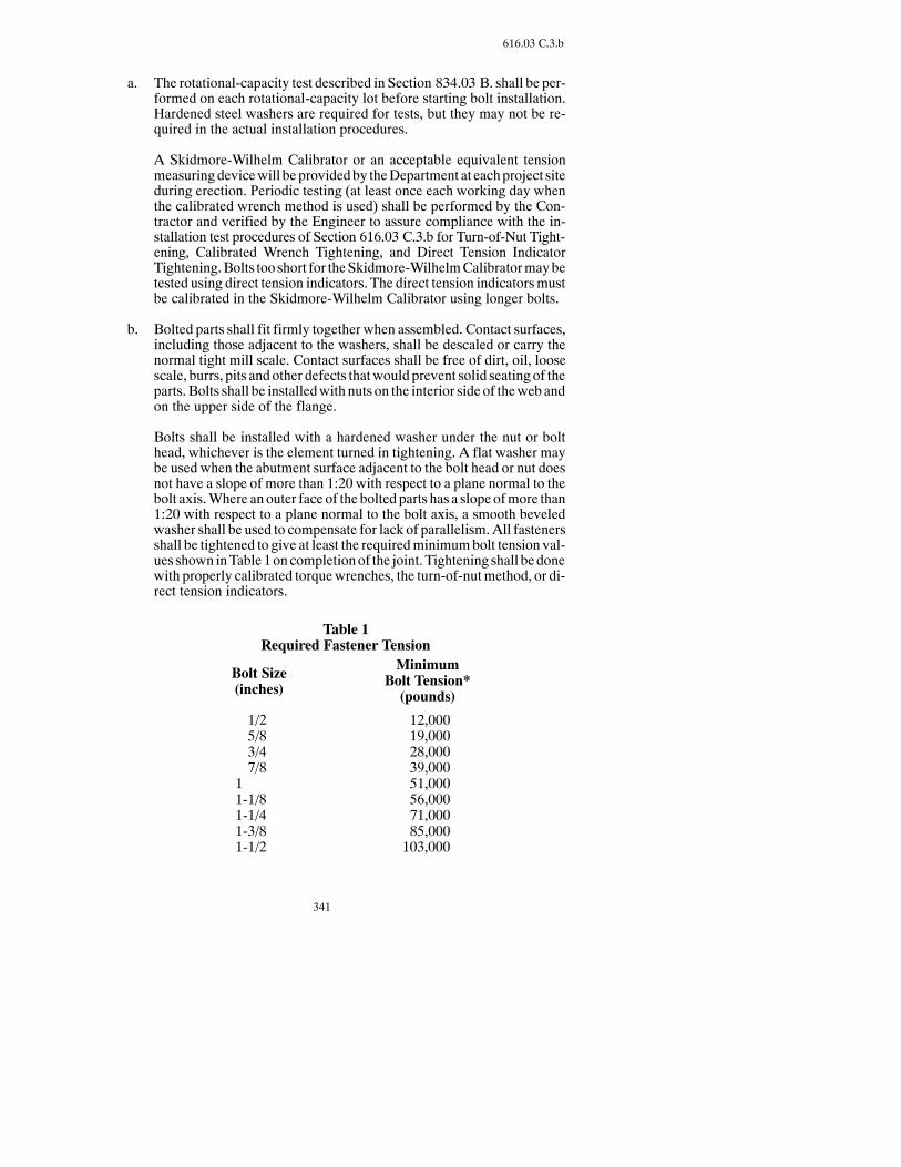
341
616.03 C.3.b
a. The rotational-capacity test described in Section 834.03 B. shall be per-formed on each rotational-capacity lot before starting bolt installation.Hardened steel washers are required for tests, but they may not be re-quired in the actual installation procedures.
A Skidmore-Wilhelm Calibrator or an acceptable equivalent tensionmeasuringdevicewill beprovidedby theDepartment at eachproject siteduring erection. Periodic testing (at least once each working day whenthe calibrated wrench method is used) shall be performed by the Con-tractor and verified by the Engineer to assure compliance with the in-stallation test procedures of Section 616.03 C.3.b for Turn-of-Nut Tight-ening, Calibrated Wrench Tightening, and Direct Tension IndicatorTightening.Bolts too short for theSkidmore-WilhelmCalibratormaybetested using direct tension indicators. The direct tension indicatorsmustbe calibrated in the Skidmore-Wilhelm Calibrator using longer bolts.
b. Bolted parts shall fit firmly together when assembled. Contact surfaces,including those adjacent to the washers, shall be descaled or carry thenormal tight mill scale. Contact surfaces shall be free of dirt, oil, loosescale, burrs, pits and other defects thatwould prevent solid seating of theparts. Bolts shall be installedwith nuts on the interior side of thewebandon the upper side of the flange.
Bolts shall be installed with a hardened washer under the nut or bolthead, whichever is the element turned in tightening. A flat washer maybe used when the abutment surface adjacent to the bolt head or nut doesnot have a slope of more than 1:20 with respect to a plane normal to thebolt axis.Where an outer face of the bolted parts has a slope ofmore than1:20 with respect to a plane normal to the bolt axis, a smooth beveledwasher shall be used to compensate for lack of parallelism. All fastenersshall be tightened to give at least the requiredminimumbolt tension val-ues shown inTable 1oncompletionof the joint. Tightening shall bedonewith properly calibrated torquewrenches, the turn-of-nutmethod, or di-rect tension indicators.
Table 1Required Fastener Tension
Bolt Size(inches)
MinimumBolt Tension*(pounds)
1/25/83/47/8
1-0/01-1/81-1/41-3/81-1/2
12,00019,00028,00039,00051,00056,00071,00085,000103,000
342
616.03 C.3.b
* Equal to 70 percent of specifiedminimum tensile strengthof bolts (as specified inASTMSpecifications for tests of full sizeA-325bolts with UNC threads loaded in axial tension).
c. High tensile strength bolts (AASHTO M 164) which have been tight-ened previously to the minimum bolt tension specified in Table 1 shallnot be reused.Anyhigh tensile strength boltwhichmust be loosenedandretightened for any reason shall be replacedwith a newbolt and nut. TheContractor shall bear the cost of bolts and nuts replaced under this re-quirement.
(1) Turn-of-Nut Tightening. When the turn-of-nut method is used toprovide the bolt tension specified in Table 1, all bolts in the jointshall first be brought to a “snug tight” condition to ensure the partsof the joint are in full contact with each other. Snug tight is definedas the tightness attainedby a few impacts of an impactwrench or thefull effort of a worker using an ordinary spud wrench. All bolts inthe joint shall then be tightened additionally by the applicableamountof nut rotation specified inTable2with tighteningprogress-ing systematically from the rigid part of the joint to its free edges.During this operation, there shall be no rotation of the part notturned by the wrench.
Table 2Nut Rotation from Snug Tight Condition (a), (b)
Disposition of Outer Faces of Bolted Parts
Bolt Length(undersideof head toend of bolt)
Both facesnormal tobolt axis
One facenormal to bothaxis and othersloped not more
than 1:20(beveled washer
not used)
Both faces slopednot more than1:20 from nor-mal to the bolt
axis(beveled washers
not used)
Up to and in-cluding 4 diameters
Over 4 diametersbut not exceeding 8diameters
Over 8 diametersbut not exceeding12 diameters (c)
1/3 turn
1/2 turn
2/3 turn
1/2 turn
2/3 turn
5/6 turn
2/3 turn
5/6 turn
1 turn
(a) Nut rotation is relative to bolt, regardless of the element (nut orbolt) being turned. For bolts installed by 1/2 turn and less, thetolerance shouldbeplusorminus30degrees; for bolts installedby 2/3 turn andmore, the tolerance should be plus or minus 45degrees.

343
616.03 C.3.c.(3)
(b) Applicable only to connections inwhich allmaterial within thegrip of the bolt is steel.
(c) No research has been performed by the Research Council onRivetedandBoltedStructural Joints toestablish the turn-of-nutprocedure for bolt lengths exceeding 12 diameters. Therefore,the required rotationmust be determinedbyactual test in a suit-able tension measuring device which simulates conditions ofsolidly fitted steel.
(2) Calibrated Wrench Tightening. Calibrated wrench tightening maybe used only when installation procedures are calibrated on a dailybasis andwhen a hardenedwasher is used under the element turnedin tightening.
Calibrated wrenches shall be set to provide a tension not less than 5percent in excess of theminimum tension specified inTable 1.Cali-bration shall be accomplished in a device capable of indicating ac-tual bolt tension by tightening three typical bolts of each diameter,length and grade from the bolts being installed andwith a hardenedwasher from the washers being used in the work under the elementturned in tightening. Wrenches shall be recalibrated when signifi-cant difference is noted in the surface condition of the bolt threads,nuts or washers. It shall be verified during actual installation in theassembled steelwork that the wrench adjustment selected by thecalibration does not produce a nut or bolt head rotation from snugtight greater than that permitted in Table 2. If manual torquewrenches are used, nuts shall be turned in the tightening directionwhen torque is measured.
Bolts shall be installed with hardened washers under the elementturned in tightening bolts in all holes of the connection and broughtto a snug tight condition. Following this initial tighteningoperation,the connection shall be tightened using the calibrated wrench.Tightening shall progress systematically from themost rigid part ofthe joint to its free edges.Thewrench shall be returned to “touchup”previously tightened bolts which may have been relaxed as a resultof the subsequent tightening of adjacent bolts until all bolts aretightened to the prescribed amount.
(3) Direct Tension Indicator Tightening. Direct tension indicators shallbe as specified in Section 834.03 C. A representative sample of notless than threedirect tension indicator devices for eachdiameter andgrade of fastener to be used in thework shall be assembled in a cali-bration device capable of indicating bolt tension. The test assemblyshall include flat hardenedwashers, if required in the actual connec-tions, arranged as those in the actual connections to be tensioned.Thecalibration test shall demonstrate that thedevice indicates a ten-sion not less than 5 percent greater than required by Table 1.
Manufacturer’s installation procedure shall be followed for instal-lation of bolts in the calibration device and in all connections. Spe-cial attention shall be given to proper installation of flat hardened
344
616.03 C.3.c.(3)
washers when direct tension indicator devices are used with boltsinstalled in oversize or slotted holes and when the load indicatingdevices are used under the turned element.
Bolts shall be installed in all holes of the connection and brought tosnug tight condition. Snug tight is indicated by partial compressionof thedirect tension indicator protrusions.All fasteners shall thenbetightened, progressing systematically from themost rigidpart of theconnection to the free edges in a manner that will minimize relaxa-tion of previously tightened fasteners. In some cases, proper ten-sioning of the boltsmay requiremore than a single cycle of system-atic partial tightening prior to final tightening to deform the protru-sion to the specified gap.
(4) Alternate Design Bolt Tightening. Fasteners which incorporate adesign feature intended to indirectly indicate the bolt tension or toautomatically provide the tension required byTable 1 shallmeet therequirements of Section 834.03 B. Verification testing using a rep-resentative sample of not less than three bolt and nut assemblies ofeach diameter, length and grade to be used in the work shall be per-formed at the job site in a device capable of indicating bolt tension.The test assembly shall include flat-hardenedwashers, if required inthe actual connection, arranged as in the actual connections to betensioned. The verification test shall demonstrate that each bolt de-velops a tension not less than 5 percent greater than the tension re-quired by Table 1. Manufacturer’s installation procedure shall befollowed for installation of bolts in the calibration device and in allconnections. Periodic retesting shall be performedwhenorderedbythe Engineer.
When alternate design fastenerswhich are intended to control or in-dicate bolt tension of the fasteners are used, bolts shall be installedin all holes of the connection and initially tightened sufficiently tobring all plies of the joint into firm contact but without yielding orfracturing the control or indicator element of the fasteners. All fas-teners shall then be further tightened, progressing systematicallyfrom themost rigid part of the connection to the free edges in aman-ner that will minimize relaxation of previously tightened fasteners.Proper tensioning of the bolts will require more than a single cycleof systematic partial tightening prior to final twist-off of the controlor indicator element of individual fasteners. If twist-off occurs priorto the final tighteningcycle, the individual fastener shall be replacedwith a new one.
4. Structural Steel. Structural steel shall be AASHTO M 270, Grade 36T2,Grade 50T2, or Grade 50WT2, except the requirement for Charpy V-Notchtest is waived for the bearings, ice nose, diaphragms, and diaphragmconnection material.
Shear connectors on splice plates shall be moved to clear bolt holes.
Shop-welded connections of diaphragm angles to gusset plates may be usedin place of the bolted connections shown. Details shall be shown on shopdrawings.

345
616.03 D.3
Field connections shall be made with 7/8-inch diameter, AASHTO M 164high-strength bolts, unless otherwise shown.
Temporary or permanent attachments or devices that are not shown on thePlans as part of the structure shall not be welded to the structural steelmembers during the fabrication and construction process.
The cost of swedge bolts shall be included in the total cost of structural steel.
5. Marking and Shipping. Each member shall be painted or marked with anerection mark for identification, and an erection diagram shall be furnishedshowing the erectionmarks. Bolts of one length and diameter, and loose nutsand washers of each size shall be packed separately. Pins, small parts, smallpackagesofbolts,washers, andnuts shall be shipped in suitable containers.Alist and description of the material shall be plainly marked on the outside ofeach container. The loading, transporting, unloading, and storing of struc-tural material shall be conducted so themetal is kept cleanwithout stressing,deforming, or damaging the structural members.
Long steelmembers shall be handledbyplacing saddles at approximately thequarter points and during storing and shipping, blocking shall be placed atintervals that prevents sag and distortion. Rolled beams and built-up plategirders shall be stored, shipped, and handled in a vertical position.
6. Shop Painting. All required painting shall meet Section 630.
7. Blast Cleaning of Unpainted Steel. After fabrication with AASHTO 270Grade 50 W steel for unpainted applications, the exterior faces of outsidebeamsor girders (including stiffeners and flanges) and other steel readily ex-posed to view shall be blast cleaned as specified in the Steel Structures Paint-ing Council Surface Preparation Specification “No. 6 Commercial BlastCleaning,” SSPC-SP 6. A corrosion inhibitor shall not be used.
Blast cleaning shall be included in the Contract Price Bid for the structuralsteel.
D. Shop Welding. Shopwelding shall meet the latest AASHTO/AWSD1.5 BridgeWelding Code except as changed by this Specification. The electroslag andelectrogas welding processes shall not be used for welding bridge members.Flange-to-web welds and shop welded splices in flanges or webs shall be per-formed using the automatic submerged arc and welding process.
1. Qualificationof Welders, Welding Operators, and Tackers.Asspecifiedin Section 105.06 D. for all welding applications
2. Built-up Plate Girders.Web plates of built up beams and girders shall becut to the prescribed camber with allowance for shrinkage due to cutting andwelding.
All shop butt welds in the flange plates shall be made before final fitting andwelding into the girders.
3. Nondestructive Testing. All nondestructive testing (NDT) of welds re-quired by the latest AASHTO/AWSD1.5 BridgeWelding Code and by Sec-

346
616.03 D.3
tions 616.03 D.4 and 616.03 D.5 of theNorth Dakota Department of Trans-portation Standard Specifications, shall be the responsibility of the Contrac-tor.
Performance of NDT shall be done by trained personnel under the observa-tion of the Engineer. The trained personnel shall have a minimum qualifica-tion as anAmerican Society for Nondestructive Testing (ASNT)NDTLevelII operator and twoyears experience at that level. Awritten report of allNDTshall be submitted to the Engineer along with material certification docu-menting compliance of the welds with contract requirements.
The cost of all NDT shall be included in the bid price for “Structural Steel.”
Methods of nondestructive testing, in addition to those specified, may beused for examination of weld passes or complete welds.
The Department may examine weld areas not designated in the Contract.
4. Radiographic and Ultrasonic Inspection.Groovewelds inmainmembersof built up girder structures shall be inspected by radiographic or ultrasonictesting as follows:
a. All tension splices and all splices subject to reversals of stress shall becompletely inspected.
b. On girder and beamweb splices, only 1/6 of the web depth beginning atthe point or points of maximum tension and 25 percent of the remainderof the web depth need be tested.
c. All compression flange splices shall be inspected.
Welds shall be tested after grinding.
Repaired welds shall be retested.
5. Magnetic Particle Inspection. At least 1 foot of every 10-foot length ofweld and 1 foot of each weld less than 10 feet in length of longitudinal beamorgirderwebbutt splices and filletwelds inmainmembers, including the endconnections, shall be testedby themagnetic particle inspectionmethod.Testsshall bemade at random locations in themembers so as to be typical for eachsize of weld and type of joint.
If rejectable discontinuities are found in any test length of weld, the fulllength of theweld or 5 feet on either side of the test length, whichever is less,shall be repaired.
Welds shall be retested after repairs are made. Retesting shall include the re-paired area plus at least 2 inches on each side of the repaired area.
E. Erection. The structure shall be erected as follows:
1. Handling and Storing Materials. Stored materials shall be kept clean andproperly drained. Steel shall be stored above ground on platforms, skids or

347
616.03 E.7
other supports. Girders, beams, and long members such as columns andchords shall be supported to prevent damage fromdeflection.Girder sectionsshall be handled with beam clamps or other approved devices and wire ropeslings shall not be used. On an erection contract, the Contractor shall checkthematerial received against the shipping lists and promptly report inwritingany shortages or damages. TheContractor shall be responsible for the loss ofor damage to any material while in the Contractor’s possession.
AASHTO270Grade 50Wsteel to be used in unpainted applications shall bestored above ground on platforms, skids, or other supports. The steel shall bekept clean and free of all foreign materials such as grease, concrete spatter,chalk or crayonmarks, dirt, or any foreignmatter that may affect the metal’snatural oxidation. Temporary protection shall be required during concreteoperations and all operations that may affect uniform natural oxidation.Loading, transporting, andunloadingof steel shall be conductedwithout sur-face damage and metal deformation.
2. Falsework, Methods, and Equipment. The falsework shall be designed,constructed, and maintained to support all loads. If required, the Contractorshall prepare and submit to the Engineer for approval, plans for falsework orfor changes in an existing structure necessary for maintaining traffic. Thesubmittal process shall be as specified in Section 616.03 A.
3. Assembling Steel. Parts shall be accurately assembled by the match markson the shop drawings.Material shall be handled so parts are not bent, broken,or damaged. Bolts or nuts with rusted or damaged threads shall not be used.Hammering which damages or distorts the members shall not be permitted.Bearing surfaces and surfaces to be in permanent contact shall be cleanedbe-fore members are assembled. Splice points in beam or girder spans shall bebrought to proper elevation and supported in position before the fasteners aretightened. High strength bolts shall be assembled according to Sec-tion 616.03 C.3.
4. Straightening Bent Material.Bent members shall be returned to the fabri-cator for repair or replacement. Bends in main structural members shall notbe straightened in the field without written permission of the Engineer.
Straightening of bent members shall be done without producing embrittle-ment, fracture, or damage.Allmaterial shall be straightenedcold.Plated, gal-vanized, enameled, heat treated or cold drawn steel and copper alloys,malle-able iron, tempered aluminum, or similar metals shall not be heated. Bentmembers that cannot be satisfactorily straightened cold shall be returned tothe fabricator for repair or replacement.
Mild steel and structural grade steel may be heated when authorized in writ-ing by the Engineer. The temperature of the heated area shall not exceed1,200°F. (a dull red) as controlledby temperature indicating crayons, liquids,or bimetal thermometers.
5. Field Painting. Structural steel shall be painted according to Section 630.
6. Field Welding. As specified in Section 105.06 D.
7. Removal of Rust Stains.When AASHTO 270 Grade 50W steel is erectedin unpainted condition, all rust stains on the substructure units after complet-

348
616.03 E.7
ing all steel and concretework shall be removedwith a concrete rust stain re-mover. All areas receiving applications of rust stain remover shall be flushedwith water.
Substructure units may be protected with reinforced polyethylene or similarmaterial which shall be left in place to prevent staining until the superstruc-ture is completed.
616.04 METHOD OF MEASUREMENT.
A. General. Structural metals placed in bridges or other structureswill bemeasuredby weight, length, area, or unit complete and in place.
TheContractor shall furnish calculatedweights andmeasurements in duplicate tothe Engineer for review and determination of final quantities.
Onlyacceptedworkwill bemeasured for payment.Dimensionsusedwill be thoseshownon thePlans, theapprovedshopdrawings, or asauthorizedby theEngineer.
B. Measurement by Weight. Measurement by weight will be by the Pound. Thequantitypaid forwill be the totalweight, determinedas specified.All castings andmiscellaneous metal parts will be measured and paid for as Structural Steel. Thefollowing pounds per cubic foot ofmetalwill be used as the basis of computation:
Aluminum, Cast or Wrought 173.0. . . . . . . . . . . . . . . . . . . . . . . . . .Brass 534.0. . . . . . . . . . . . . . . . . . . . . . . . . . . . . . . . . . . . . . . . . . . .Bronze, Cast 536.0. . . . . . . . . . . . . . . . . . . . . . . . . . . . . . . . . . . . . .Bronze, Wrought 555.0. . . . . . . . . . . . . . . . . . . . . . . . . . . . . . . . . . .Copper, Sheet 558.0. . . . . . . . . . . . . . . . . . . . . . . . . . . . . . . . . . . . .Iron, Cast 445.0. . . . . . . . . . . . . . . . . . . . . . . . . . . . . . . . . . . . . . . . .Iron, Malleable 470.0. . . . . . . . . . . . . . . . . . . . . . . . . . . . . . . . . . . . .Lead, Sheet & Plate 707.0. . . . . . . . . . . . . . . . . . . . . . . . . . . . . . . . .Steel (all kinds) 490.0. . . . . . . . . . . . . . . . . . . . . . . . . . . . . . . . . . . .Zinc, Sheet 450.0. . . . . . . . . . . . . . . . . . . . . . . . . . . . . . . . . . . . . . . .
1. Structural Steel and Wrought Metals. The weight of all permanent bolts6 inches or less in length, thin nuts, field shims, ring fills, shop and fieldwelds, shop and field painting, galvanizing, metallizing, and all other inci-dental metal items for which no direct weight measurement is made will notbe measured or paid for and will be included in the Contract Price Bid forStructural Steel. Except as provided, the weight will be computed from di-mensions shown on the Plans, the approved shop drawings, or as authorizedby the Engineer. Deductionswill not bemade for cuts, copes, bevels, or openholes; and allowance will not be made for mill overruns.
2. Structural Plates. The weight of rectangular plates (such as web plates,cover plates, batten plates, etc.) will be computed on the basis of the netlength andwidth shown on the Plans. Allowancewill not bemade for planedor sheared edges.
The weight of each plate or irregular shape will be computed on the basis ofthe dimensions of the smallest rectangular plate from which it can be cut.When plates are machine finished, the dimension of the plates will be the
349
616.04 C.1
maximum machine finished dimension plus 1/8 inch for each finished sur-face.
3. Structural Shapes and Bars. The weight of all bars and structural shapeswith square ends will be computed on the basis of the net section and thelength as shown on the Plans.
Identical structural shapes, less than 5 feet long, with mitered ends will beconsideredmultiple cut. Their total weightwill be computed as theweight ofthe shortest parent section fromwhich they can be cut, provided the length ofthe parent section is not be more than 30 feet.
Except as provided above, the weight of each structural shape with miteredendswill be computedon the basis of the section andoverall lengthmeasuredparallel to the axis of the shape.
4. Pins and Rollers. The parent section for forged segmental rollers will beconsidered square in section, and of the same length, width, and thickness asthe finished roller.
The weight of hot-rolled bar steel pins and rollers will be computed on thebasis of the length shown on the Plans and on the basis of a diameter 1/4 inchgreater than that of the finished pin or roller. The weight of cold finished barsteel pins and rollers will be computed on the basis of the net length and di-ameter shown on the Plans.
5. Bolts and Tie Rods. The weight of bolts over 6 inches long and tie rods in-cluding necessary nuts andwashers used for connecting structural steel partswill be computed from the nominalweights as given in the current handbookof the American Institute of Steel Construction. These weights will be in-cluded in the weight of “Structural Steel.”
6. Castings. The weight of each casting will be computed from the net dimen-sions shownon the approved shopdrawings,with anadditionof10percent tocompensate for fillets andoverruns.Wherevermachine-finishedsurfacesarerequired, an allowance of 1/8 inch in thickness will bemade for each surfaceso finished. When cored holes are shown on the Plans, a deduction will bemade for the full size of the core.
7. Pipe. The weight will be computed from the dimensions shown on the Plansand the nominal weights of the pipe and fittings.
8. Sheet Metal. The weight will be computed from the smallest rectangulararea from which the developed surface can be cut.
C. Lump Sum Basis.When Structural Steel is measured and paid for on a “LumpSum”basis, it includes all Structural Steel required under this Section andwill notbemodified unless design Plan changes are ordered by the Engineer. The follow-ing conditions will apply to the lump sum basis:
1. The estimated weight of Structural Steel computed according to Section616.04 B will be shown on the Plans. If any change in design is made whicheffects theweightofmaterial furnished,payment for theadditionalStructural

350
616.04 C.1
Steel required as a result of the changewill bemade at a unit price per pound.This unit price will be obtained by dividing the Lump Sum bid for StructuralSteel by the total estimatedweight ofStructural Steel shownon thePlans.Re-duction in weight due to changes in design will be made at the same calcu-lated rate, and will be deducted from payments due.
2. Prospective Bidders shall verify the estimated weight of Structural Steel be-fore submitting a bid.Adjustments other than for authorized changeswill notbe made in the Lump Sum bid even though actual weight may deviate fromthe stated estimated weight.
616.05 BASIS OF PAYMENT.
Payment will be made at the Contract Unit Price as follows:
Pay Item Pay UnitStructural Carbon Steel AASHTO 270 Grade 36 PoundsHigh Strength Low-Alloy Columbium VanadiumSteel AASHTO 270 Grade 50 Pounds
High Strength Low-Alloy Structural Steel with 50,000 psiMinimum Yield Point to 4 inch Thick AASHTO 270Grade 50 W Pounds
Castings PoundsPipe PoundsSheet Metal PoundsStructural Steel Lump Sum
This payment will be full compensation for all labor, equipment, andmaterials neces-sary to complete the work.
SECTION 618TIMBER STRUCTURES
618.01 DESCRIPTION.
This work consists of constructing timber structures.
618.02 MATERIALS.
Materials shall meet the following:
Item SectionTimber 844.01Timber Connectors 844.02 ATimber Preservatives 846Timber Treatment 846Hardware 844.02 BPaint 852
Structural glued laminated timber shall meet U.S. Product Standard PS 56-73 forStructural Glued Laminated Timber. The term “structural glued laminated timber” as
351
618.03 B
employed in PS 56-73 is an engineered, stress-rated product of a timber laminatingplant, comprising assemblies of suitably selected and prepared wood laminations se-curely bonded together with adhesives. The grain of all laminations is approximatelyparallel longitudinally. The separate laminations may not exceed 2 inches (.051 m) innet thickness. They may be comprised of pieces which are end-joined to form anylength, or of pieces placed or glued edge to edge tomakewider ones, or of pieces bentto curved form during gluing.
618.03 CONSTRUCTION REQUIREMENTS.
A. General. All timber shall be stored to shed water and to prevent distortion andwarping. Untreated timber shall be open stacked. Treated timber shall be closedstacked.
All timber shall be handled without splitting or damaging the surface and edges.Treated timber shall be handled without breaking through the surface penetratedby the treatment.
All cutting, framing, and boring of treated timber shall be done before treatment.
Timber to be included in the finished structure shall not be used for temporary fal-sework, staging, etc.
Temporary bolting, spiking, or nailing shall not be used on treated timber.
B. Fabrication.All lumber and timber shall be accurately cut and framed to a closefit so the joints have an even bearing over the entire contact surfaces. Joints shallnot be shimmed nor shall open joints be used.
The size of holes bored in untreated timber shall be as follows:
1. Round drift bolts or dowels -- 1/16 inch less in diameter than the size of thedrift bolt or dowel.
2. Squaredrift bolts or dowels -- diameter of the hole equal to the sidedimensionof the drift bolt or dowel.
3. Bolts -- same diameter as the bolt.
4. Rods -- 1/16 inch greater than the diameter of the rod.
5. Lag screw shank -- same as the nominal size of the lag screw.
6. Lag screw thread -- same diameter as the body of the screw at the base of thethread.
All holes in timberbefore treatment shall be1/16 inch larger than specifiedabove.
All cuts or abrasions in treated timber, after having been carefully trimmed, shallbe given three applications of hot creosote oil and covered with roofing pitch.
All holes in untreated timber (except handrails) and treated timber shall be treatedwith hot creosote oil so all of the hole surface is thoroughly coated with the oil.
352
618.03 B
Treating shall be done before inserting or driving bolts, lag screws, rods, and driftpins. All unfilled holes, after being treated with creosote oil, shall be filled withtight-fitting creosoted plugs.
All stringers shall be sized to a uniform depth at bearings. Dapping or sizing shallbe done on the better edge of the piece, placing this edge downward.
Bolts shall be the sizes specified and long enough to extend completely throughthe nuts. Extrawashers shall not be used on bolts that are too long, and galvanizedbolts shall not be rethreaded. Bolts, dowels, etc. which are not galvanized shall begiven two coats of iron oxide paint before installation.
Nails and spikes shall be driven so the heads are flushwith the surface of thewoodwithout leaving hammer marks.
Grooves for split ring timber connectors shall be accurately cut.Other timber con-nectors shall be embedded in the timber bypressure alone.Mauls, sledges, etc. forembedding the connectors shall not be used.
C. Excavation.All excavation for placing timber abutments andmud sills, concretepedestals for bents, and bents shall be done before the piles are driven. This exca-vation will not be measured for payment.
D. Erection.Piles in anyonebent shall be selectedby size to avoidbendingor distor-tion of the sway bracing. Cutoffs shall be accurately made to assure full bearingbetween the caps and piles of a bent. Tops of piles shall not be shimmed.
Mud sills for framed bents shall be firmly and evenly bedded to solid bearing andtamped in place.
Concrete pedestals to support framed bents shall be smoothly finished so the sillsor posts have an even bearing.
Sills shall have true and even bearing on mud sills, piles, or pedestals. All earthshall be removed from contact with sills so there is free air circulation.
Posts shall be framed true and shall have full bearing on both sills and caps.
Timber caps shall be placed to secure an evenanduniformbearingover the topsofthe supporting posts or piles, and to secure an even alignment of their ends.
Planks in floors shall be securely spiked toeachstringerwith two6-inch spikes for3-inch plank, and two 7-inch spikes for 4-inch plank. Planks in walls shall be se-curely spiked to each pile or post with two 7-inch spikes for 3-inch plank.
In 2-inch laminated floors, each 2-inch strip shall be nailed to the adjacent stripwith 40 d spikes placed 24 inches center to center and staggered 8 inches with thespikes in the adjacent strip. In 3-inch laminated floors, each 3-inch strip shall benailed to the adjacent stripwith 50 d spikes spaced 18 inches center-to-center andstaggered9 incheswith the spikes in the adjacent strip. In addition, each strip shallbe toe-nailed to every second stringer with a 16 d nail, the nailing of successivestrips being staggered so the spacing of the nails along each stringer shall be twotimes the thickness of one strip.

353
618.04 C
Floor plank and strips less than8 feet in length shall not be used.Where it is neces-sary to usemore than one length of floor plank or strip for transverse flooring, thejoints between ends of plank or strip shall bemade over a joist or stringer. Splicesshall be staggered and shall not occur over a common joist or stringer closer thanevery fourth plank or strip.
All backing plank shall be nailed to each stringer or pile with two 7-inch spikes.
If splitting is observed while nailing superstructure or substructure elements, asmall pilot hole shall be bored for each spike.
E. Salvaging Timber for Reuse. All timber to be reused from an existing bridgeshall be removed, cleaned of all nails, spikes, bolts and foreign material, andstored without damage. Timber material that is damaged or lost shall be replacedat the Contractor’s expense.
All bolt and nail holes in reused timber shall be treated with creosote, and unusedholes filled with creosoted plugs. Cuts and abrasions in reused timber shall becarefully trimmed and given three applications of hot creosote and covered withhot tar.
F. Painting. Timber shall not be painted.
G. Backfilling. Backfilling shall meet Section 210.
618.04 METHOD OF MEASUREMENT.
Quantities of various items in completed and accepted structureswill bemeasured forpayment according to theContract for the pay items, and in the terms of the prescribedunits for those items. Only accepted workwill be included and the dimensions will bethose shown or authorized in writing by the Engineer.
On timber bridges, all metal items and incidental non-metallic itemswill not bemeas-ured and paid for directly, but will be included in the Contract prices for the pay itemslisted in the Contract.
A. Untreated and Treated Timber. The unit of measure for Untreated Timber andTreated Timber will be the Thousand Feet Board Measure (MBM), and theamount to be paid for will be the actual number of (MBM) in the completed andaccepted structure computed as follows: actual sizes of full sawn timber andnominal sizes of dressed timber will be used. The length used will be the nearestcommercial (multiples of 2 feet) lengths fromwhich the representative pieces canbe cut; except for pieces less than 10 feet in length, the lengths used will be thenearest commercial lengths, not exceeding 24 feet, fromwhich the pieces can becut in multiples.
B. Glued Laminated Stringers and Glued Laminated Deck Panels. The unit ofmeasure for Glued Laminated Stringers and Glued Laminated Deck Panels willbe the number, “Each,” of the size and length designated in the Contract.
C. Treated Timber Structure and Untreated Timber Structure.When the Pro-posalFormstipulatespaymentwill bemade forTreatedTimberStructure andUn-

354
618.04 C
treated Timber Structure on a Lump Sum basis, all labor, materials, equipment,etc., except piling, necessary to complete the work shall be included in the LumpSum bid. Piling will be measured and paid for as specified in Section 622.
618.05 BASIS OF PAYMENT.
Payment will be made at the Contract Unit Price as follows:
Pay Item Pay UnitUntreated Timber MBMTreated Timber MBMGlued Laminated Stringers EachGlued Laminated Deck Panels EachTreated Timber Structure Lump SumUntreated Timber Structure Lump Sum
This payment will be full compensation for all labor, equipment, andmaterials neces-sary to complete the work.
SECTION 622PILING
622.01 DESCRIPTION.
This work consists of furnishing and driving piles, including test piles.
622.02 MATERIALS.
Material shall meet the following:
Item SectionUntreated Timber Piling 840.02Treated Timber Piling 840.02Steel Piling 840.01 ASteel-Encased Concrete Piling 840.01 BSteel Sheet Piling 840.03 ACorrugated Steel Sheet Piling 840.03 BCreosote Preservative Treatment for Timber 846Paint 852
622.03 CONSTRUCTION REQUIREMENTS.
A. Test Piles.
1. General. The Contractor shall furnish and drive test piles of the type, size,number, length, and at the location specified.

355
622.03 A.2
Test piles shall bedrivenusing the same type and size of hammer tobeused todrive regular foundation piles to final bearing.
Test piles shall not be drivenuntil excavation to the elevation of the bottomofthe footinghasbeencompleted, or a hole larger than thediameter of thepile isprebored down to the elevation of the bottom of the footing in which the pileis driven.
Test piles shall be driven to a minimum of 125 percent of the design-bearingload or as required for a load test.
When a timber test pile is driven to Plan length and does not achieve 125 per-cent of design bearing load, the Engineer will determine if an additional,longer test pile is required.
A follower to drive test piles shall not be used.
The lengths and number of piling shown on the Plans are estimated for bid-ding purposes and the length of the pile to be furnishedwill be determined bythe Engineer from the results of driving test piles.
2. Pile Formulas. The formulas shown shall be applied when computing thebearing value by pile penetration for all piles. Penetration measurements todeterminepile bearingvalues shall not bemadewhenpile heads aredamagedby burring, corrugating, or crushing or immediately after fresh cushioningmaterial has been inserted over the head of the pile. In the absence of loadtests, the safe bearing value of piles shall be determined by the following for-mulas unless otherwise specified:
3.5 WHS + 0.4
W + 0.2 MW + M
P = ×
3.5 ES + 0.2
W + 0.2 MW + M
P =
For gravity hammers
For double acting orsingle acting steamor air hammers anddiesel hammers
. . . . . . . . . . . . .
. . . . . . . . . . . . .×
Where:
P = Safe bearing value, in pounds.W = Weight of striking parts (ram), in pounds.H = Height of free fall of ram, in feet.M = Weight of parts being driven, in pounds. Includes pile weight, anvil
(if any), driving cap, etc.E = Energy per blow, in foot-pounds.S = Average penetration of pile in inches per blow for last five blows for
gravity hammer and the last ten blows for steam, air, or diesel ham-mer.
The preceding formulas are applicable only when:

356
622.03 A.2.a
a. The gravity hammer has a free fall.
b. The head of the pile is free from broomed or crushed fiber.
c. The penetration of the pile is at a reasonably uniform rate.
d. There is no noticeable bounce after the blow.When there is a noticeablebounce, twice the height of the bounce shall be deducted from“H” to de-termine the value of “H” in the formula.
The bearing value of timber piles, as determined from formulas, shall be con-sideredeffectiveonlywhen theyare less than the safeworkingstresses for thematerials ofwhich the piles aremade.Whenwater jets are usedwith the driv-ing, the bearing value shall be determined by the formulas from the results ofdriving after the jets have been withdrawn.
B. Pile Driving. Piling shall not be driven unless the Engineer is present and wasgiven at least 24 hours advance notice of any pile driving operations.
Pile shall not be drivenwithin 80 feet of concretewhichhas cured less than3days,or a greater distance if determined necessary by the Engineer.
Before driving foundation piles, the excavation shall be completed to the bottomof the footing elevation.
Any excess excavation and voids remaining after pile driving is completed shallbe backfilled and compacted to the bottom of the footing elevation with founda-tion fill, at the Contractor’s expense.
Timber piles may be sharpened at the tip.
A steel head block or cap fitted to the pile head shall be used to prevent damage tothe pile head. The head block or cap shall be providedwith a shock block or cush-ion.Wherenecessary, bandsshall beused toprevent splitting in thebodyof timberpile.
Pile driver leads shall be used for all types of hammers. They shall allow freemovement of the hammer and rigidly hold the pile in correct alignment during thedriving operation.
The driving of piling with followers is not permitted.
Whenspecifiedpenetrationcannotbeobtainedwithoutdamaging thepile, theEn-gineer may approve the use of jetting, preboring, or spudding to secure the re-quired penetration. The final driving shall be with the hammer for determiningbearing.
Whenpilingsaredriven throughaconstructedembankment, havinga thicknessof5 feet ormore below the bottomof footing, the embankment shall be prebored foreach pile. All pilot holes not completely filled by piles shall be backfilled withsand or fine gravel before the substructure is built.
Sawingor cutting thebodyof apile to assist in springing it to proper location isnotpermitted. If a pilevibrates excessivelyor showssignsofbucklingduringdriving,it shall be braced or guyed to assure satisfactory results.
357
622.03 C.1
Damaged piles shall be replaced or corrected.
Sections of piling that become part of the structure shall not be reduced in cross-section by drilling or burning holes for handling purposes. Any section of pilingthat is drilled or burned shall be removed and not incorporated into the structure.
During the driving of foundation piling, the pile shall not deviate from theverticalor from the specified batter more than 1/2 inch per foot of pile length. After driv-ing, the center of the pile at the cutoff shall not be more than 6 inches from Planlocation. Piling that are not driven to these tolerances will be rejected.
During driving, the piles for trestle bents shall not deviate from the vertical orfrom the specified batter more than 1/4 inch per foot of pile length. After driving,the piles shall support the cap in its proper position with full bearing on each pile.Piling that are not driven to these tolerances will be rejected.
Steel and precast concrete trestle piles shall be driven between guides rigidly heldin position during the driving. The guides shall be securely braced to adjacent pil-ing or to temporary piling.
Steel-encased concrete piles shall be driven using a steel combination drivinghead and pilot of the proper size to ensure properly distributed hammer blows onthe pile shells to prevent damage. Clearance between the pilot ring and the pileshell shall not exceed 1/4 inch. A cushion block of timber shall be used betweenthehammer and thedrivinghead.Dimensionsof thepile shell shall be as specifiedon the Plans. The end enclosure plate shall be circular, not less than 3/4 inch inthickness, and not be larger in diameter than the outside diameter of the pile shell.
Adequate lighting shall be provided for inspection of the pile shell throughout itsentire length. Improperly driven, broken, and defective pile that is not watertight,shows bends, kinks, or other deformations shall be removed and replaced or re-paired by and at theContractor’s expense. The tops of pile shells that are not filledwith concrete immediately after driving shall be sealed temporarily to prevent theentrance of water or foreign substances.
All pile shells for any one bent, pier, or abutment shall be completely driven be-fore any concrete is placed in the pile shells. If this is not practical, the remainingpile shells shall not be driven until the concrete in all pile shells attains a compres-sive strength of 2,000 pounds psi.
Thepiledrivingoperationsarenotconsideredcompleteuntil all heavedpileshavebeen redriven.
C. Pile Hammers.
1. General. The pile hammer shall meet the requirements of energy and ramweight as specifiedunless theContractor canprovewith a load test that pilingdriven with a smaller energy hammer holds, without failing, a load at least2-1/2 times the specified bearing. This proof test load shall be at theContrac-tor’s expense. If not specified, theminimum foot-pounds of energy per blowdeveloped by steam, diesel, or air hammer shall not be less than 10,000 foot-pounds nor less than two times theweight of the pile in pounds, whichever isgreater.Asteam, diesel, or air hammer shall beoperated at its ratednumber ofblows per minute while determining bearing.
358
622.03 C.2
2. Gravity Hammer. Theminimumweight of a gravity or “drop” hammer fordriving steel or steel-encased concrete piles shall not be less than 4,000pounds nor less than the combined weight of the pile and driving head,whichever is greater. Theminimumweight of a gravity or “drop”hammer fordriving all other piles shall not be less than 3,000 pounds nor less than theweight of the pile and driving head, whichever is the greater. The fall of thehammer shall be regulated to avoid damage to the pile and shall not exceed15 feet for timber and steel piling, or 10 feet for steel-encased concrete piling.
3. Diesel Hammer.Whenusingadiesel hammer, themaximumfoot-poundsofenergy per blow used in computing the driving bearing of individual pilesshall be themanufacturer’s rated energywith the following applicable reduc-tions:
a. When using open top type diesel hammers, a reduction in the rated en-ergy shall bemade if the hammer does notmaintain theminimummeas-ured stroke. This reduction shall be based on the percentage of the re-duced stroke.
b. When using a closed top type diesel hammer, themaximumenergy shallbe the rated energy subject to the condition that the Contractor shall fur-nish an appropriate readable gauge and chart to measure the bouncechamber pressure and resulting hammer output. If no instrument is pro-vided, an independent testing firm shall be furnished to perform dy-namic testing on the piling. The testing shall be at the Contractor’s ex-pense.
4. Air Hammer. When using an air (or steam) hammer, the maximum foot-pounds of energy per blow for computing the driving bearing of individualpiles shall be the acceptedmanufacturer’s energy rating subject to the follow-ing condition:
When using double-acting air (or steam) hammers, the manufacturer’srated energy is applicable only when the required pressure (mean effec-tive) is properly delivered to the hammer as specified by the manufac-turer. When pressure at the hammer is below that specified, the energyshall be adjusted downward according to E = H(W + AP).
Where:
E = Energy per blow, in foot-pounds.H = Height of fall, in feet.W = Weight of striking parts (ram), in pounds.A = Area of piston, in square inches.P = Steam (or air) pressure at the hammer in pounds per square inch.
When the use of an air (or steam) hammer is proposed, the Engineer shall befurnished a descriptive catalog showing the essential Specifications neces-sary to determine hammer output.
D. Bearing Value.The design load of foundation piles in a substructure unit and theminimum penetration will be shown on the Plans.

359
622.03 F.2
Piling shall be driven to obtain the minimum penetration and design load, or to apenetration andbearingdetermined by theEngineer.Bearing value shall be deter-mined by the formula specified which is applicable to the type of hammer used.
If the Engineer determines that it is necessary to drive piles through thin layers ofhardmaterial underlaidwith softmaterial, the pile driving forces through the thinlayers may exceed the anticipated driving forces needed to obtain the specifiedbearing.
E. Cutoff and Treatment of Pile Heads.
1. Timber Piles. The tops of all timber piling shall be cut off to the planes andelevations specified.Pileswhich support timber capsor sills shall be sawed tothe plane of the superimposed structure. The head of the cutoff pile shall besound, undamaged wood.
All cuts and abrasions in treated timber piles shall be given three applicationsof hot creosote oil and covered with roofing pitch. All holes bored in treatedtimber piles shall be given two applications of hot creosote before the boltsare placed.
The heads of treated timber piles which are imbedded in concrete shall begiven three heavy applications of hot creosote oil and a thick layer of roofingpitch.
The heads of all cut off treated timber piles for trestle bents, wing piles, andfoundation piles for timber bents shall receive the following treatment:
A ring ofmetal shall be provided near the edge of the top of the pile. Oneinch of creosote oil shall be placed inside the ring and on top of the pilefor 36 hours to assure adequate penetration of the end fibers. The end ofthepile shall be coveredwitha thick layer of roofingpitch.Acircular capof aluminum, not lighter than 25 U.S. gauge and not smaller than6 inches larger than the diameter of the pile, shall be neatly bent andcrimped around the sides of the pile. The lower edges of the aluminumcap shall be covered with a strip of aluminum (at least 2 inches wide) ofthe samegradeand thickness, using2-inchaluminumnails for fastening.
2. Steel Piling and Steel-Encased Concrete Piling. Steel piles shall be cutoff at the established elevation.When steel capplates are specified, the cutoffshall be at 90 degrees to the axis of the pile and shall be cut true to provide fullbearing over the entire cross section of the pile.
Final cutoffs shall be approximately 90 degrees to the axis of the pile.
F. Extensions.
1. Timber Piling. Full length timber piles shall be used.
2. Steel Piling and Steel-Encased Concrete Piling. When it is necessary toincrease the length of steel piles and steel-encased concrete piles, an addi-tional length may be spliced to the original length. The sections shall be ofidentical cross-section. Steel piling and steel-encasedconcrete piling shall bespliced by welding according to Plan details.

360
622.03 F.2
Splices shall provide andmaintain true alignment and position of the compo-nent parts of the pile during and after installation. Field splices in steel pileshells shall develop the full strength of the shell and shall be watertight.
The minimum lengths of pile which may be spliced by welding shall not beless than 5 feet. A shorter length may be used to make the last splice belowcutoff.
Steel piling sections spliced together byweldingwhile in horizontal positionshall not exceed the following variation in straightness in inches:
1/8 inch × number of feet of total length10
Only qualified welders shall splice steel piling and steel-encased piling. Forsplicesmadewith thepile in thehorizontal position, thewelder shall bequali-fied for position 3G (vertical groove) and 4F (overhead fillet). For splicingvertical reinforced concrete pile shells and vertical steel H-pilingwithout re-inforcing plates, the welder shall be qualified for position 2G (horizontalgroove). For splicingvertical steelH-pilingwith reinforcingplates, theweld-er shall be qualified for position 2G (horizontal groove), 3F (vertical fillet),and 4F (overhead fillet). The cost of testing and certification shall be at theContractor’s expense. Test welds shall be witnessed by a representative ofeither the Department or an independent testing agency.
A copy of the welder’s qualification test certificate shall be subject to ap-proval by the Engineer before the welder performs any welding. Approvalwill be for one year from the date of qualification. Approval of the welder’scertification may be requested for additional periods of one year, up to amaximum of three one-year extensions, if the welder has been actively en-gaged at welding in the required positions within the previous six months.The Department has the right to require a requalification test at any time.
Steelmaybeweldedup toand including3/4-inch thicknesswithout theuseofpreheat when the base metal temperature is not lower than 50°F. If the basemetal temperature is lower than 50°F., the base metal shall be heated to atleast 50°F. and the temperature maintained during welding.
When the air temperature approaches 0°F., welding shall not be done untilprotection has been provided which keeps the air temperature surroundingthe work above 0°F.
When preheating the base metal is required, it shall be performed so the sur-facesof thepartsonwhichmetal isbeingdeposited,within three inchesof thepoint of welding both laterally and in advance of thewelding, are at or abovethe 50°F. temperature specified. Base metal shall not be preheated to morethan 400°F.
No welding shall be done in rain, snow, or sleet, or high wind without ade-quate protection.
Electrodes shall meet “Carbon Steel Covered Arc Welding Electrodes”AWS-A5.1, Classification E6010, E6011, or E7018.

361
622.04
Three certified copies of test reports shall be furnished of all pertinent re-quired tests of AWS-A5.1 made on electrodes of the same class, size, andbrand; andwhichweremanufactured by the same process andwith the samematerials as the electrodes furnished. The tests may have been for processqualification or quality control and shall have beenmadewithin one year be-fore manufacture of the electrodes furnished. Three copies of the manufac-turer’s certification shall be furnished that the process and material require-ments were the same for manufacturing the tested electrodes and the fur-nished electrodes.
All electrodes while in the original unbroken package shall be stored in awarm, dry roomorotherweatherproof location.Openpackagesof electrodesshall be immediately stored in a holding oven at a temperature of at least250°F. Electrodes that are removed from the container or holding oven forwelding, shall not be exposed to the atmosphere for more than four hourswithout redrying for twohours at between450°F. and500°F.Electrodes shallnot be redried more than once. Electrodes that have been wet shall not beused.
G. Steel-Encased Concrete Piling.
1. Filling with Concrete.Concrete shall not be placed in pile shells containingwater or any foreign substance.
The pile shall be filled with Class AE Concrete meeting Section 802. Theconcrete shall bedeposited inone continuousoperationand the rate of depos-iting shall be moderated to avoid formation of air pockets.
Theconcrete footingor cap shall notbeplaceduntil at least two hoursafter allpiles within the pile group are filled with concrete.
2. Reinforcement. Reinforcement for the steel-encased piles shall be used ifspecified. Reinforcement shall be a rigidly tied cage. Reinforcement shall beplaced at a clear distance of one inch from the face of the pile shell, and shallbe providedwith spacers to ensure the specified clearance for the bars. Rein-forcement shall meet Section 612. Concrete shall be placed in the shell to apoint approximately two feet below the bottom elevation of the reinforcingsteel assembly before placing the reinforcing steel assembly in the pile shell.
H. Painting. Parts of steel piles and steel-encased concrete piles exposed to view inthe finished structure shall be painted according to Section 630.03 D.3. Portionsof those piles extending above a level of three feet below the final ground surfaceelevation shall be painted. Galvanized piling may be used in lieu of painting.
622.04 STEEL AND CORRUGATED STEEL SHEET PILES.
The sheet piles shall be drivenwith a hammer of sufficientweight and driving capacityto overcome the inertia of the pile and the resistance of the soil, without peening orupsetting the pile ends. A driving cap made expressly for the type of sheeting beingdriven shall be used.
Any sheet pile broken because of defects or improper driving, driven out of proper po-sition, or driven below Plan cutoff shall be removed and replaced at the Contractor’sexpense.
362
622.04
Damaged galvanized sheet piling surfaces shall be repaired by applying a paste of ap-proved zinc powder and flux with a minimum amount of water. The surface to becoated shall be heated sufficiently with a torch so all metallics in the paste are meltedwhen applied. Repair shall be at the Contractor’s expense.
622.05 METHOD OF MEASUREMENT.
A. Timber, Steel, and Steel-Encased Piling. The footage of Timber, Steel, andSteel-Encased Piles to be paid for will be the actual number of Linear Feet of pil-ing left in place in the completed work as accepted by the Engineer. Concrete andreinforcing steel used in Steel-Encased Concrete Piling will not be measured asseparate items. All cutoffs become the Contractor’s property.
B. Test Piles.Test Piles will bemeasured either by the number of Test Piles actuallyfurnished, driven, and accepted by the Engineer; or by the number of Linear Feetof Test Pile specified, even if a lesser footage is actually furnished, driven and ac-cepted by the Engineer. The Plans will indicate which type of measurement is tobe used. Pilingmeasured for as Test Pile will not be included in themeasurementof pay footage of Piling. All cutoffs become the Contractor’s property.
C. Corrugated Steel and Steel Sheet Piling. The unit of measure for CorrugatedSteel and Steel Sheet Piling will be the “Square Foot,” and the quantity to be paidfor will be the number of Square Feet of piling actually remaining in the com-pleted structure andaccepted.Thearea insquare feetwill beobtainedbymultiply-ing the nominal width (distance center to center of joint) by the total length of theSheet Piles remaining in place after the cutoff.
D. SteelPileSplices.Theunit ofmeasure for SteelPile Spliceswill beonepile splicewhich includes labor, equipment, materials, preparation of weld surfaces, andwelding necessary to complete the splice. The quantity to bemeasuredwill be thenumber of pile splices determined as follows:
Steel Pile Splices locatedwithin the pile length called for or the length deter-mined by the Engineer will not bemeasured. If a Test Pile is not required, thenumber of splices to be measured for payment will be those located at or be-yond the length specifiednecessary to increase the lengthof apile incorporatedinto the structure over the length specified. If aTestPile is required, thenumberof splices to be measured for payment will be those located at or beyond thelength determined by the Engineer necessary to increase the length deter-mined by the Engineer. Steel Pile Splices required to increase the lengths ofTest Piles over the lengths shown on the Plans and located at or beyond thelengths shown on the Plans will be measured for payment.
622.06 BASIS OF PAYMENT.
A. The linear feet or square feet of piling for each type of pile provided will be paidfor at the Contract Unit Price except that the Unit Price for Timber Piling will beadjusted according to the following conditions:
When the Contractor is required to order individual Timber Pile lengthswhich are longer or shorter than the Plan length, the Contract Unit Price willbe increasedor decreasedby the difference between the actual invoice cost ofthe piling ordered and the actual invoice cost of the Plan length piling.

363
622.06 D.2
No reduction in the Contract Unit Price will be made on piles shown to be45 feet in length or less and ordered to a lesser length.
In all cases, the adjusted unit pricewill apply to the full length of pile remain-ing in place in the completed work and accepted by the Engineer.
Adjustment in Timber Piling prices will be made for each footing.
B. Test pilemeasuredas statedwill bepaid for at theContractUnit Price for each typeof Test Pile.
C. When the final in-place quantity of each size of Steel or Steel-Encased Pilingdriven and accepted for payment varies from the original estimated quantity, theContractorwill be compensated for thedifference in the twoquantities as follows:
1. When the final piling quantity of each size underruns the Plan quantity bymore than 25 feet, theContractorwill receive 20 percent of theContractUnitPrice for the entire difference in quantities. Payment for the in-place and ac-cepted piling will be at Contract Unit Price.
2. When the finalpilingquantityof eachsizeoverruns thePlanquantitybymorethan 25 feet, the Contractor will receive the Contract Unit Price plus 10 per-cent for the excess over Plan quantity. Payment for Plan quantity of the in-place piling will be at Contract Unit Price.
3. No adjustment will be made when the final in-place quantity of piling foreach size varies from the original estimated quantity by 25 lineal feet or less.
Provisions of Section 104.03 B.2 will not be applied to piling quantities.
If it becomes necessary to drive Timber Piles of greater length than is shown, theadditional length driven will be paid according to Section 104.03.
When it is necessary to driveSteelTestPiles orSteel-EncasedTestPiles of greaterlength than that shown, the additional length drivenwill bepaid for at theContractUnit Price per foot for “Steel-Encased Concrete Piling” or “Steel Piling.”
D. Pile Cutoff is defined as the difference between the measured length of the pilingfurnished, but not exceeding the length specified, and the length actually drivenand incorporated in the structure.
1. Paymentwill bemade forPileCutoff onTreated andUntreatedTimberPilingunder the following conditions:
a. Cutoff used in the work as piling will not be paid for as cutoff.
b. Payment for Pile Cutoff will be at the receipted invoice price deliveredon the Project.
c. All Pile Cutoff not used in the work as pilingwill remain the property ofand shall be disposed of by the Contractor.
2. Paymentwill not bemade for Pile Cutoff on Steel or Steel-EncasedConcretePiling.
364
622.06 E
E. The accepted quantity of Steel Pile Splices will be paid for by the followingmethod for each pile splice:
1. SteelH-Pile. Four times theContractBid Price per foot of regular foundationpiling of the same size spliced.
2. Steel-Encased Concrete Pile. Three times the Contract Bid Price per foot ofregular foundation piling of the same size spliced.
SECTION 624RAILINGS
624.01 DESCRIPTION.
This work consists of furnishing and installing metal railings for bridges, curbs, side-walks, parapets, wingwalls, or retaining walls.
624.02 MATERIALS.
Materials shall meet the following:
Item SectionStructural Steel 834.01Miscellaneous Metals 834.02Paint 852Galvanizing 854Ornamental Metal Railing As shown on the Plans
624.03 CONSTRUCTION REQUIREMENTS.
Steel fabrication and erection shall meet Section 616.
Bolts with self-locking nuts shall be placed with the heads toward the roadway orwalkway.
Welded joints shall be finished by grinding or filing to provide a neat appearance.
Steel railing shall be galvanized.
Aluminum railing shall be cleaned of all dirt and foreign matter, and polished to pro-vide a uniform appearance.
624.04 METHOD OF MEASUREMENT.
The unit of measure for Railing will be the total number of Linear Feet of Railing inplace and accepted, measured along the Railing centerline as specified.

365
626.02 B
When a separate Bid Item is not included for Railing, the Railing will be measured bythe Pound or Lump Sum basis as specified for Structural Steel in Section 616.
624.05 BASIS OF PAYMENT.
Payment will be made at the Contract Unit Prices as follows:
Pay Item Pay UnitRailing Linear Feet
This payment will be full compensation for all labor, equipment, andmaterials neces-sary to complete the work.
SECTION 626COFFERDAMS
626.01 DESCRIPTION.
This work consists of designing, constructing, dewatering, maintaining, removing,and backfilling all cofferdams necessary for constructing footings.
Cofferdam shall designate any temporary or removable structure designed to hold thesurrounding earth, water, or both out of the excavation. A cofferdam may be con-structed of earth, timber, steel, concrete, or a combination of these. It includes earthendikes, timber cribs, any type of sheet piling, and removable steel shells or any similarconstruction.
626.02 CONSTRUCTION REQUIREMENTS.
A. General. Cofferdams for foundation construction shall be carried to adequatedepths and heights. They shall be designed and constructed to be safe and as wa-tertight as necessary for the proper performance of the work which must be doneinside them. Interior dimensions shall give sufficient clearance for constructionand exterior inspection of forms, and placement of pumping equipment.
Cofferdams which tilt or move laterally during the process of sinking shall berightedor enlarged toprovide thenecessaryclearanceat theContractor’sexpense.
Cofferdams shall be constructed to protect green concrete against damage from asudden rising of the stream and to prevent damage to the foundation by erosion.No timber or bracing which extends into the substructure shall be left in the sub-structure without approval of the Engineer.
B. Excavation. Excavation inside the cofferdam that is within the limits defined inSection 210.04 A shall be paid for by the class of excavation designated on the

366
626.02 B
Plans. Other excavation costs inside the cofferdam but outside the limits definedin Section 210.04 A will be included in the bid item “Cofferdams.”
C. Removal of Cofferdams.Cofferdams shall be removedwhen no longer needed.Excavation shall not be removed below the natural channel bottom outside thecofferdam to facilitate sheeting removal.
After the cofferdam is removed, Ordinary Backfill shall be used to fill the exca-vatedarea to thenatural channelbottom.OrdinaryBackfill shall be included in thebid item “Excavation.”
D. Seal Concrete. Concrete foundation seals shall be constructed and paid for ac-cording to Section 602.
E. Pumping.Pumping fromthe interiorof any foundationenclosure shall notbeper-mitted during placement of concrete, or for at least 24 hours after placement, un-less it is done froma sump separated from the concretework. Pumping to dewatera sealed cofferdam shall not begin until the seal has set sufficiently to withstandthe hydrostatic pressure.
626.03 METHOD OF MEASUREMENT.
When the Proposal Form includes a quantity for Cofferdams, each Cofferdamwill bemeasured as a unit. This unit shall include all Cofferdams required in the constructionof any pier or abutment.
626.04 BASIS OF PAYMENT.
Payment will be made at the Contract Unit Price as follows:
Pay Item Pay UnitCofferdams Each
When the Cofferdam is installed, 70 percent of the Contract Unit Price will be paid.The remaining 30 percent will be paid when the Cofferdam is removed and disposedof.
Anymodification of aCofferdammade necessary by a change inPlanswill be paid foraccording to Section 104.03.
This payment will be full compensation for all labor, equipment, andmaterials neces-sary to complete the work.
SECTION 630PAINTING
630.01 DESCRIPTION.
Thisworkconsists of furnishingall paints andpaintmaterials; preparing surfaces tobepainted; applying, protecting, and drying paint coatings; and protecting all traffic, ad-
367
630.02 A.2.c
jacent property, and the work itself against spatters or other damage due to paintingoperations.
The shoppaint system for newstructural steel shall consist of an inorganic zinc silicateprimer and a compatible high-build, aliphatic polyurethane finish coat, both with thesame manufacturer. After fabrication and before shipment, the primer and finish coatshall be applied to all surfaces except as specified.
The field applied system shall be an aluminum filled epoxymastic primer and a com-patible high-build, aliphatic polyurethane finish coat, both with the same manufac-turer. This system is intended for rehabilitation painting of existing steel structures. Itis also intended for coating field splices as well as touch-up of damaged areas of shopapplied coats on new structural steel after erection.
630.02 MATERIALS.
A. Inorganic Zinc Silicate Primer. The inorganic zinc silicate primer shall be atwo-component self-curing typewhich,whenmixed and appliedby themanufac-turer’s instructions, cures without the use of a separate curing solution meets therequirements of AASHTO M 300, and has the following properties:
1. Composition: Zinc dust shall meet ASTMD 520 Type I, modified to allow0.1 percent retained on the No. 100 sieve. The vehicle component shall con-sist primarily of a partially hydrolyzed ethyl silicate in an appropriate sol-vent. The mixed paint shall have the following properties:
a. Zinc portion shall be at least 72 percent by weight of the total solids ofthe dried coating.
b. Total solids shall be at least 78 percent by weight.
c. The color shall be a distinct contrast with the blast cleanedmetal and thefinish coat.
2. Corrosion Resistance: Test panels meeting ASTM D 609, having mini-mumdimensionsof 2 inches×5 inches×1/8 inch, shall bepreparedbyclean-ing all surfaces per SSPC SP-10 with a one 3 mil profile. A 3 mil Dry FilmThickness (DFT) coating shall be applied and cured according to the manu-facturer’s recommendations. Individual test panels must pass the followingtests:
a. Fresh Water Resistance. Panels shall be scribed down to base metalwith an “X” having at least 2-inch legs and immersed in tap water at75±5°F. The panels shall show no rusting, blistering, or softening after30 days. Solution shall be replenished after 7 and 14 days.
b. Salt Water Resistance. Resistance shall be the same as 630.02 A.2.aexcept panels shall be immersed in 5 percent sodium chloride solution.
c. Salt Fog Resistance.Panels shall be scribeddown tobasemetalwith an“X” having at least 2-inch legs. Panels shall then be tested according toASTMB 117. After 1,000 hours the panels shall show no loss of adhe-sion, rusting, blistering or softening.

368
630.02 B
B. High-Build Aliphatic Polyurethane Finish Coat. The high-build aliphaticpolyurethane finish coat shall be a two-component, weather resistant semiglossfinish topcoat, compatiblewithpreviouslyappliedcoat, andshall have the follow-ing properties:
1. Solidsbyweight shall beminimumof62 percent. Solidsbyvolumeshall be aminimum of 54 percent.
2. The coating shall not run or sag when applied at 10milsWet FilmThickness(WFT), unthinned.Thecoatingmustbe sprayable toauniformsemigloss fin-ish when thinned to the maximum level specified by the manufacturer.
3. The coating color shall be as specified.
C. Aluminum Filled Epoxy Mastic Primer. The aluminum filled epoxy masticshall be a two-component epoxy. The epoxymasticmust adhere to rusty steel anddeteriorated coating systems.The epoxymastic shall contain a rust inhibiting sys-tem which controls undercutting of the paint film.
1. Composition.Theprimarypigment shallbealuminum.Leadcontainingpig-ments shall not be present. The vehicle shall be of the epoxy-type and shallnot contain coal tar. The curing agent shall allow trouble free applicationdur-ing normal humidity conditions (20 percent to 60 percent relative humidity).
The epoxymastic shall contain at least 70 percent solids by volumemeetingASTM D 1644. (Modified to a dry time of 72 hours at 100°F., rather thanthree hours at 105°C.)
2. Flexibility.A five mil (DFT) coating of the epoxymastic shall be applied ona 1/8-inch × 30-inch × 4-inch steel panel sandblasted according to SSPCSP-5. The coating shall be cured for two weeks at 75°F. The coating shall notcrack or lose adhesion after the panel is uniformly bent around an 8-inch di-ameter mandrel.
3. Resistance.The epoxymastic shall meet or exceed the resistance testswhenapplied in the followingmanner: Steel panels, 2 inches × 5 inches× 1/8 inch,meeting ASTM D 609, shall be sandblasted according to SSPC SP-5. Thepanels shall be exposed to theweather for 30 days so uniform rusting occurs.Exposed toweather means stored outdoors at least 30 feet fromwalls, build-ing or other obstruction to air or moisture movement. The panels shall behand cleaned with a wire brush according to SSPC SP-2. The epoxy masticshall be spray applied to the panels at 6 mils DFT in one coat. The coatingshall be cured as recommended by the manufacturer.
a. Fresh Water Resistance. Panels shall be scribed down to base metalwith an “X” having at least 2-inch legs and immersed in tapwater at 75±5°F.After 30 days the panel shall be unaffected except for discoloration.There shall be no blistering, softening, or visible rusting of the coatingbeyond 1/16 inch from the center of the scribe.
b. Salt Water Resistance. Resistance shall be the same as 630.02 C.3.aexcept panels shall be immersed in 5 percent sodium chloride solution.The solution shall be replenishedwith fresh solution after 7 and14 days.
369
630.03 A
c. Salt Fog Resistance.Panels shall be scribeddown tobasemetalwith an“X” having at least 2-inch legs. Panels shall then be tested according toASTM B 117.After 1,000 hours, the coating shall showno loss of bond,rusting, or blistering beyond 1/16 inch from the center of the scribedmark.
d. Weathering Resistance. Panels shall be tested according toASTM G 23, Type D. Testing shall begin on the wet cycle. After1,000 hours, the coating shall show no rusting, loss of adhesion, or blis-tering.
D. Certification and Final Acceptance. Before use of any paint system, the De-partment shall be furnished a certified test report from an independent testinglaboratory. This certified test report shall show that the specific test results meetall quantitative requirements and resistance test requirements of these Specifica-tions. The certified test report shall contain the exact ratio, by weight, of the pig-ment component to the vehicle component of the paint used for the tests, the lottested, the manufacturer’s name, brand name of paint, and date of manufacture.New certified test results shall be submitted any time the manufacturing processor the paint formulation is changed. New certified test results may be requiredwhen random sampling and testing of material offered for use indicates noncon-formance to any of the requirements specified.
To obtain final acceptance of the paint system, a certification shall be furnishedstating that thematerial usedwas the same as thematerial tested formanufacturerand brand name approval. TheDepartmentmay sample and test any or allmateri-als supplied.
E. Packaging and Labeling.
Two-component paint shall be packaged in two-component containers or intwo separate containers. The components shall be packaged and proportioned sothatwhen thepigment ismixedwith thevehicle, it yields 5 gallonsofmixedpaint.
Each container shall bear a label which clearly shows the name of the manufac-turer, the brand name, and the lot number of the paint. The label on the vehiclecontainer shall include complete instructions for use of this paint, shelf life of thecomponents, and pot life of the mixture. The container shall be coated to preventattack by the paint components.
630.03 CONSTRUCTION REQUIREMENTS.
A. General.
The coatings shall be applied by themanufacturer’s recommendations. Awrittencopyof these recommendations shall be furnished to theDepartment. The recom-mendations shall include the mixing and thinning directions; the recommendedspray nozzles and pressures; the minimum drying time; and the procedures forcoating bolts, nuts, and washers.
Coatings shall be applied in a uniform, even coat and shall be worked into all cor-nersandcrevices.Coatingsshall beappliedwithequipmentmeeting themanufac-

370
630.03 A
turer’s application recommendations. On surfaces inaccessible to spray, the coat-ings may be applied with sheepskin daubers.
Surfaces with unsatisfactory coatings shall be reblasted, cleaned, and recoated atthe Contractor’s expense.
During fabrication, coating application, erection, and field repairs, scaffolding orlift platforms shall be provided to permit inspection of the steel.
B. Shop Painting Structural Steel.
1. Surface Preparation.
Surfaces to be coated shall be free of oil or grease prior to blast cleaning. Sur-faces coated with oil or grease shall be solvent cleaned according to SSPCSP-1.
Surfaces to be coated shall be blast cleaned to a nearwhite finish according toSSPC SP-10.Abrasives used for blast cleaning shall be either clean dry sand,steel shot, mineral grit, or manufactured grit and shall have a gradation thatprovides a uniform steel surface profile of 1 to 2.5 mils.
Fins, tears, slivers, weld splatter, and burred or sharp edges shall be removedby grinding and the area shall be reblasted to provide the profile specified be-fore painting.
Blast residue shall be removed from steel surfaces with a commercial gradevacuumcleaner equippedwithabrush-typecleaning tool, or bydoubleblow-ing. Steel shall be kept dust free, dry, and primedwithin 24 hours after clean-ing prior to rust onset.
2. Mixing and Thinning Paint.
All coatings shall be thoroughly mixed so the pigment is completely in sus-pensionand theconsistency isuniform.Thezincprimer shall be strainedovera sieve having openings no larger than a No. 50 sieve and then continuouslyagitated until application is completed.
Thinning for proper application shall be accomplishedby themanufacturer’srecommendations.
3. Coating Application.
a. Prime Coat.All structural steel surfaces, including the shearconnectorsand the upper surface of the top flange shall be primed in the shop. Theshop-applied prime coat shall be an inorganic zinc prime coat. Applica-tion shall meet SSPC PA-1 and shall be sprayed.
After cleaning the surfaces, the prime coat shall be applied. The DFT ofthe prime coat shall be in accordance with the manufacturer’s writtenrecommendations when measured according to SSPC PA-2.
Areas of deficient primer thickness shall be thoroughly cleaned withpowerwashing equipment to remove all dirt. These deficient areas shallbe wire brushed, vacuumed, and recoated.

371
630.03 C
Where excess coating thickness produces “mud cracking,” the coatingshall be repaired according to the manufacturer’s instructions.
All primed surfaces shall be inspected for cleanliness and for the pres-ence of loose zinc and zinc oxidation products (white oxides). Whenneeded, the surface shall be cleaned by wiping, brushing, or flushingwith fresh water.
b. Finish Coat.The shop-applied finish coat shall beahigh-buildaliphaticpolyurethane finishcoat.ApplicationshallmeetSSPC PA-1andshallbesprayed. The DFT of the finish coat shall be in accordance with themanufacturer’s written recommendations when measured according toSSPC PA-2.
The finish coat shall not be applied until the prime coat is approved. Theminimum curing time between coats shall be as recommended by themanufacturer.
Splice plates and filler plates shall not be finish coated in the shop. Con-tact or faying surfaces of bolted field splices of themainmembers, shearconnectors, and the upper surface of the top flanges shall bemaskeddur-ing the finish coat application.
To prevent top coat bubbling, amist coat shall be required. Themist coatshall consist of a fast pass of the spray gun to seal the surface of theprimer followed immediately by a full wet coat.
Where excessive coating thickness produces “mud cracking,” the coat-ing shall be scraped back to soundly bonded coating and the area shall berecoated.
C. Handling, Shipping, and Erecting.
Steelmaterial shall not be loaded for shipment until the shop coating has been ap-proved. The steel shall not be damaged in the shop, during shipment, during erec-tion, and during subsequent construction of the bridge. Overhang brackets shallbe padded where they bear on the web. Deck formwork shall be mortar tight toprevent leakage onto the girders. The coating shall be protected from all chains,slings, hooks, andother apparatus used to lift or turn the coated steel.During ship-ment, girders, diaphragms andother steel parts shall be padded andpacked to pre-vent damage. The steel shall be stored off the ground on padded supports so theycannot fall on or touch one another. The steel shall not be shipped until the neces-sary equipment is available for handlingand storing the steel. Theproposedmeth-ods for handling and storing the steel shall be submitted at the preconstructionmeeting.
Contact or faying surfaces of bolted field splices of main members includingspliceplates and filler plates, shall becovereduntil final assembly.Contaminationfrom oil, grease, paint, etc., of these primed surfaces shall be removed by sand-blasting to bare metal and recoatedwith shop primer. No other coatingwill be al-lowed on these surfaces. The intention is to provide clean, inorganically coatedfaying surfaces for field splices.
372
630.03 D
D. Field Painting.
1. General.
a. Weather Conditions. Paint shall only be appliedwhen the air tempera-ture is at or above50°F. andbelow100°F.Paint shall notbe appliedwhenthe air is misty, dusty, or otherwise unsatisfactory for work. The surfacetemperature of the steel shall be 5 degrees above the dew point (exhibitsno moisture condensation) before painting is permitted.
b. Application. Field painting shall not be accomplished until the form-work is removed.
Fieldpainting shall beperformedwithanaluminum-filledepoxy-masticprimer and a finish coat of high-build aliphatic polyurethane. The DFTof theprimer and the finish coat shall be in accordancewith themanufac-turer’s written recommendations.
Paint shall be appliedduringdaylight hours by brushingor spraying.Af-ter application, the paint film shall be smooth and uniformwithout skipsor areas of excessive paint.When spraying results in unsatisfactory sur-faces, paint shall be applied by brushing. The previously-applied coat ofpaint shall be cured before the next coat is applied.
Only airless spray painting equipment shall be used. Paint shall be con-tinuallyagitatedduring the sprayingoperationandapplied ina fine, evenspray. The operator shallmanipulate the spray so the paint has a uniformthicknesswhen dry. If necessary, the paint shall be immediately brushedout to secureuniformcoverage andeliminate runs,wrinkling, blistering,and air holes. If adequate coverage cannot be obtained at rivets, boltheads, nuts, corners, and edges, paint shall be applied to these areas byhand brushing before spraying.
c. Protection.All parts of the structure and adjacent property shall be pro-tected from spatters of paint or paint materials. Canvas shields or othermeans may be required to protect traffic. Freshly painted surfaced shallbe protected to prevent dust and dirt from contacting these surfaces.
Protective shields shall be provided so paint drift does not damage adja-cent parts of the structure and adjacent property. Spray painting shall besuspended whenever the application or drift is not being properly con-trolled.
d. Responsibility for Paint Damage Claims.TheContractor shallhavearepresentative available at the job site to receive and promptly processpaint damage claims. The Contractor, or representative, shall record thenameandaddress of the claimant, date, andnature of damage; amount ofmonetary damages sought, date paid; and promptly report all claims tothe Engineer.
2. Field Painting New Structural Steel.
After assembly, exposed surfaces of nuts, bolts, andwashers shall be cleanedwith a mineral spirit solvent followed by a hot water rinse. After these sur-

373
638.02
facesare thoroughlydry, they shall begivenacoatof aluminum-filledepoxy-mastic prime coat, and coated with polyurethane finish coat.
Damaged finish coated areas shall be repaired by cleaning and applying theepoxy mastic primer before applying the finish coat.
Surfaces coated with inorganic zinc silicate primer shall be inspected fordamage and cleanliness before finish coating. Damaged areas shall be re-paired by primingwith epoxymastic. Necessary cleaning shall be done withhot water or steam. The finish coat shall not be applied until all cleaning andrepairing has been inspected and accepted.
3. Rehabilitation Painting.
Surfaces to be coated shall be prepared by blast cleaning. The level of prepa-ration shall meet SSPC SP-6, “Commercial Blast Cleaning.” Existing paintremaining along the edges of blast-cleaned areas shall be feathered andcleaned to assure a bond of new to old paint.
630.04 METHOD OF MEASUREMENT.
Measurement for painting shall be a Lump Sum item for furnishing and delivering allpaintmaterials, preparing the surfaces and applying the primer and finish coat of paint.
If there is no bid item for Sandblasting and Painting, this work shall be included in thebit item for “Structural Steel.”
630.05 BASIS OF PAYMENT.
Payment will be made at the Contract Unit Price as follows:
Pay Item Pay UnitSandblasting and Painting Lump Sum
This payment will be full compensation for all labor, equipment, andmaterials neces-sary to complete the work.
SECTION 638STRUCTURAL PLATE CULVERTS
638.01 DESCRIPTION.
This item consists of furnishing, assembling, and backfilling structural plate pipe, el-liptical structural plate pipe, pipe arches, or arches.
638.02 MATERIALS.
Material shall meet Section 830.02.

374
638.03
638.03 CONSTRUCTION REQUIREMENTS.
A. Excavation. Excavation shall meet Section 714.03 A.1 and as modified here.
When a pipe structure is erected in a trench, the width of the trench shall be suffi-cient to permit thorough tamping of the earth backfill.
B. Bedding. Bedding shall meet Section 714.03 A.2.
C. Assembly and Installation. Pipe shall be assembled by the manufacturer’s as-sembly instructions. Care shall be exercised in the use of drift pins or pry bars toprevent chipping or injury to the galvanized coating.
D. Backfill. After assembling the pipe, the backfill shall be placed uniformly andequally on each side of the pipe in layers not to exceed 12 inches before compac-tion. Adequate earth cover shall be placed over the structure before heavy con-struction equipment is driven over it. Compaction of each layer of the backfillshall be equal to the compaction as described in Sections 714.03 A.6 and 714.03A.7.
638.04 METHOD OF MEASUREMENT.
A. Linear Basis. When the linear unit quantity is shown on the bid schedule, thestructural plate pipe, elliptical structural plate pipe, arches, or pipe arches will bemeasured inLinear Feet, installed in place, completed, and accepted. The numberof Linear Feet will be measured as shown on the Plans for the particular item.
B. Lump Sum Basis.Each structural plate culvert shall be the type, size, gauge, andlengthdesignatedand, for thepurposeofmeasurement andpayment, shall be con-sidered as a unit installed in place, completed, and accepted.
638.05 BASIS OF PAYMENT.
Payment will be made at the Contract Unit Price as follows:
Pay Item Pay UnitStructural Plate Pipe Linear Foot, Lump SumElliptical Structural Plate Pipe Linear Foot, Lump SumPipe Arch Linear Foot, Lump SumArch Linear Foot, Lump Sum
This payment will be full compensation for all labor, equipment, andmaterials neces-sary to complete the work.
SECTION 650REPAIR AND OVERLAY OF
PORTLAND CEMENT CONCRETEBRIDGE DECKS WITH LOW-SLUMP CONCRETE
650.01 DESCRIPTION.
This work consists of removing unsound concrete or chloride contaminated soundconcrete with mechanical or hydrodemolition equipment and replacing and resurfac-ing the bridge deck with low-slump concrete.

375
650.02 B.7
650.02 MATERIALS.
A. General.
Item SectionClass AAE-3 Concrete 802Portland Cement 804.01Concrete Admixtures 808Burlap 810Water 812Fine Aggregate 816.01Coarse Aggregate* 816.02
*Coarse aggregate for Portland Cement Concrete shall be crushed stone with at least 75 percent byweight of the particles retained on the No. 4 sieve having at least one fractured face. Aggregate shallmeet Size No. 5.
B. Special Requirements for Low-Slump Concrete.
1. Cement. Type I or IA cement shall be used.
2. Basic absolute volume per Unit Volume of Concrete:
Coarse Aggregate (Size 5) 0.3121Fine Aggregate 0.3121Air 0.0600Water 0.1603Cement (Type I or IA) 0.1555
1.0000
3. Approximate quantities of dry materials per cubic yard of concrete:
Coarse Aggregate (Size 5) 1,393 lbs.Fine Aggregate 1,393 lbs.Cement (8.75 bags) 823 lbs.
These quantities are based on the following assumptions:
Specific gravity of cement 3.14Specific gravity of aggregate 2.65Weight of one cubic foot of water 62.4 lbs.
4. An approved water-reducing admixture shall be used.
5. The slump measured using AASHTO T 119 shall not exceed 1 inch.
6. The concrete shall have an entrained air content of 6 percent with a toleranceof plus or minus 1 percent. The method of entraining air shall meet Section802.01 D.
7. Grout for bonding the overlay to the existing concrete shall consist of equalparts, by weight, of Portland Cement and fine aggregate mixed with suffi-cient water to form a stiff slurry. The slurry shall have a consistency that per-mits application with a stiff brush or broom to a thin even coating that does
376
650.02 B.7
not run or puddle in low spots. For sealing construction joints, the grout shallbe thinned as necessary.
650.03 EQUIPMENT.
A. Surfacing Preparation Equipment. Surface preparation equipment shall be ofthe following types:
1. Mechanical Equipment.
a. Scarifying equipment shall meet Section 152.05 or 153.15.
b. Sawing equipment shall meet Section 153.12.
c. Sandblasting equipment shall remove rust scale from reinforcing barsand small chips of concrete partially loosened bymilling. Air lines usedfor sandblastingorhighpressure air blast shall be equippedwith filters toremove all oil from the air.
d. Power driven hand tools, such as pneumatic hammers, shall not be heav-ier than the nominal 30-pound class and shall be operated at an angle of45 degrees or less measured from the slab. Chipping hammers heavierthan a nominal 15-pound class shall not be used to remove concretearound or beneath reinforcing bars. Pointed bits for power hammersshall not be used except for full depth removal.
e. Hand tools such as hammers and chisels shall be used for removal of fi-nal particles of unsound concrete or to achieve the require depth.
2. Hydrodemolition equipment shall meet Section 153.16.
B. Proportioning and Mixing Equipment. Proportioning and mixing equipmentshall beof a self-containedmobile type (not conventional ready-mix truck),meet-ing Section 153.02 C.
C. Placing and Finishing Equipment.
1. Placing and finishing equipment shall include hand tools for placing andbrushing-in freshly mixed mortar, and for distributing material to the depththat can be struck off with the screed. Hand operated vibrators and screedsshall be used to place and finish small areas of work.
2. Adragandametal tiningdevicemeetingSection 602.03B.2 shall beused forthe final finish.
650.04 REMOVAL AND OVERLAYWITH THE USE OF MECHANICALEQUIPMENT.
A. Classification of Overlays.
1. Class 1 Overlay. Class 1 overlay consists of removing deck concrete to adepth of 1/2 inch below the existing finished surface, except at drains andelsewhere as specified; disposing of the removed concrete; and overlaying
377
650.04 B.1
with concrete to the depth specified. Thickness of the concrete overlay shallbe measured from a level 1/2 inch below the original surface to the finalraised surface as specified.
2. Class 2 Overlay. Class 2 overlay areas will be determined by the Engineerafter Class 1 overlay has been accomplished. Class 2 overlay consists of re-moval, disposal, and replacement of concrete belowthebottomof theClass 1overlay. The lower limit of the Class 2 overlay shall be the top of the bars inthe top layer of reinforcing steel. Concrete removed below the top of the topbar coincidental with Class 2 overlay is part of the Class 2 overlay area. Theexcavated volume shall be replaced with concrete to a level bounding theClass 1 overlay.
3. Class 2-AOverlay.Class 2-A overlay areaswill be determined by the Engi-neer after Class 1 and Class 2 overlay have been accomplished. Class 2-Aoverlay consists of removal, disposal, and replacement of concrete aroundthe periphery of reinforcing bars in the topmat. Class 2-A overlaywill be or-deredwhenan isolatedbarhas lost bondonmore than1/2of it circumference.The excavated volume shall be replaced with concrete bounding the Class 2overlay.
Class 3 overlay may be ordered in lieu of Class 2-A overlay if damage tosound concrete between bars is suspected.
4. Class 3 Overlay. Class 3 overlay areas will be determined by the Engineerafter Class 1 and Class 2 overlay have been accomplished. Class 3 overlayconsists of removal, disposal, and replacement of concrete below the bottomof theClass 2 overlay to sound concrete or to amaximumdepth bound by thetop of the top bar of the bottommat of reinforcing steel. The excavated vol-ume shall be replaced with concrete to a level bounding the Class 2 overlay.
5. Class 4 Overlay. Class 4 overlay will be determined by the Engineer afterClass 1, Class 2, and Class 3 overlay have been accomplished. Class 4 over-lay consists of removal anddisposal of concrete below the level described forClass 3 overlay and for the full remaining depth of the deck and replacementof the excavated volume with AAE-3 Portland Cement Concrete or low-slump concrete to a level bounding the Class 1 overlay.
Edges of the full depth hole in the deck shall be nearly vertical or tapered in-ward fromtop tobottom.Areverse taperwill not bepermitted.Theundersideof the completed deck replacement shall have a neat, smooth appearance.
B. Construction Requirements.
1. General.
All concrete aggregate shall be available for sampling and testing, for amini-mum of five days before lane closure. The Department is not responsible fordelays or additional costs caused by failing aggregate.
Asphalt overlays shall be removed before any concrete removal. Asphalt re-moval equipment shall not damage the surface of the concrete deck.
To ensure proper overlay thickness, measurements shall be made from thefinisher screed to the prepared deck surface.

378
650.04 B.1
The deck surface shall be sandblasted and cleaned with compressed air aftergrinding and concrete removal operations are completed. Wet sandblastingshall not be used.
All reinforcing steel shall be thoroughly sandblast cleaned of all deleteriousmaterial and concrete. Reinforcing bars which have lost 1/4 or more of theiroriginal dimensions shall be removed and replaced with a new lap-splicedbar. Reinforcing bars damageddue to removal operations shall be replaced atthe Contractor’s expense.
2. Removal Requirements.
a. Class 1 Overlay. The existing concrete deck area shall be uniformlyground to a depth of 1/2 inch. Removal to a greater depth shall be re-quired at drains and other noted locations.
b. Class 2Overlay.Concrete shall be removed by chipping or by a combi-nationof grindingandchipping.Removal shall be considered to start 1/2inch below the existing surface.
c. Class 2-AOverlay.Concrete shall be removed from around the periph-ery of the reinforcing steel using power hammers andhand toolswithoutcutting, stretching, or damaging any exposed reinforcing steel. A mini-mum clearance of 3/4 inch around the bar shall be attained.
d. Class 3 Overlay. Concrete shall be removed by chipping with powerhammers and hand tools without cutting, stretching, or damaging anyexposed reinforcing steel.
e. Class 4Overlay.Thiswork consists of complete removal of that portionof the bridgedeckwhich theEngineer designated for full depth removal.Forms shall be provided to enable placement of new concrete.
3. Mixing of Materials.
a. Class AAE-3 Concrete. Concrete shall be mixed according to Sec-tion 802.
b. Low-SlumpConcrete.Concrete shall be mixed at the site. The mixingrate shall allow finishing operations to proceed at a steady rate.
4. Placing, Finishing, and Curing Overlay.
a. General.
At longitudinal construction joints, the surface course previously placedshall be sawn to a straight and vertical edge before the adjacent course isplaced.
After the machine finishing has been completed, hand finishing with awood float may be required to produce a tight, uniform surface.
Immediately after finishing, all vertical joints with adjacent concreteshall be sealed by painting with a thinned grout before the curing opera-tion begins.

379
650.04 B.5
A drag shall be pulled over the surface in a longitudinal direction whilethe concrete is plastic. It shall be immediately followedwith a transversemetal tine finish. The tining shall be stopped 18 inches from the face ofthe curb. The tining device shall be drawn transversely across the fullwidth of the pavement without overlapping passes. The tining shall beneat and uniform, and shall produce grooveswithout tearing the surfaceor bringing course aggregate to the surface. The finished surface shall befree from rough or porous areas and irregularities resulting from im-proper handling of the device. Concrete surfaces which do not meet theabove requirements shall be corrected at the Contractor’s expense bycutting transverse grooves in the hardened concrete with diamond-bladed equipment.
The surface tolerance of the finished concrete overlay shall be less thanor equal to 3/16 inch in 10 feet. Measurements for smoothness will betaken on approximately 2-foot spacing over the entire deck.Anyportionof the deck not meeting the tolerance shall be corrected by grinding orreoverlaying the deck. The tined surface texture shall be restored withdiamond bit cutting equipment. Grinding or grooving that decreases thecover to less than 1-1/2 inches over the top of the reinforcing steel shallnot be used.
b. Special Requirements for Low-Slump Concrete.
Concrete for Class 1, 2, 2-A, and 3 overlay areas may be placed in oneoperation.
Where full depth concrete is required, Class AAE-3 or low-slump con-crete may be used. Concrete for the Class 4 overlay areas shall be struckoff at the bottom level of Class 1 unless the Class 4 falls entirely with aClass 2 or 3 overlay area. In that case, the concrete shall match the pre-pared surface of either the Class 2 or 3 overlay area. The concrete shallreceive thewet curemeetingSection 602.03F.3 for at least 72hours, andshall be sandblasted and cleaned before overlaying.
The prepared deck surface shall be dry to permit absorption of the bond-ing grout. All vertical and horizontal surfaces shall receive a thorough,even coating of bonding grout at a controlled rate so that grout does notdry before covering with new concrete.
The concrete shall be screeded to final grade and consolidated to 98 per-cent of the unit weight using AASHTO T 121.
The surface shall receive a wet cure meeting Section 602.03 F.3 exceptthat the curing period shall be five days. Concrete that is not wet curedwithin 30 minutes after placement shall be removed to the original pre-pared surface and replaced at the Contractor’s expense.
5. Limitations of Operations.
Nopreparationworkwill be alloweduntil the laneor strip is closed for traffic.This lane shall remain closed until the overlay has been completed.

380
650.04 B.5
No loads other than equipment needed to remove and replace concrete shallbe allowed on the deck that has undergone preparation before placement andcuring of concrete.Mixers shall not be operated on the structure. Equipmentused for transporting concrete shall not damage the prepared deck surfaceand shall be designed for transporting concrete. Equipment shall not leak oil,hydraulic fluid, or any other contaminant onto the prepared deck surface.Equipment used to transportmortar or concrete shall be of sufficient size andadequate design to handle the volume of material without spilling or drip-ping.
No vehicular traffic shall be permitted on the new overlay until the specifiedcuring period is completed. If daily mean temperatures fall below 55°F. dur-ing the five days following concrete placement, additional curing days willbe required.
When temperaturesareabove80°F., placement shall bemadeatnightor earlymorning hours by installing and operating necessary lighting. Reschedulingan overlay placementmay be required if weather conditions adversely effectthe quality of the overlay.
Overlays shall not be placed unless the temperature is 45°F. and rising.
Bridge deck overlays shall not be placed after September 15 unless author-ized by the Engineer.
C. Method of Measurement.
1. Class 1, 2, 3, and 4Overlay. The quantities of Class 1, Class 2, Class 3, andClass 4 Overlay will be measured by the Square Yard. Removal of asphaltoverlay will be included in this bid item.
2. Class 2-A Overlay. The quantity of Class 2-A Overlay will be measured inLinear Feet.
D. Basis of Payment.
1. Quantities measured will be paid for at the Contract Unit Price for the payitemsshown.Paymentwill be full compensation for all labor, equipment, andmaterials necessary to complete the work. This includes removal, disposal,and replacement of all concrete for Class 1, 2, 2-A, 3, and 4 overlays.
When there is no item forClass 4overlay, paymentwill bemade according toSection 104.03. Any Class 1, 2, 2-A, or 3 overlay authorized before Class 4overlay, shall be paid for at the unit bid prices.
Noadjustment inunit bidprices, according toSection 104.03B,will bemadefor Class 2, 2-A, 3, or 4 Overlays.
2. If it becomes necessary to increase the average thickness of the Class 1 over-lay over that provided on the Plans, the following procedure will be used todetermine compensation for the additional concrete required:
Step 1:Before scarification, the existing deck elevations will be determinedby longitudinal profiles taken along lines corresponding to the edges and

381
650.05 B.1
mid-width of each overlay pour. The elevations along each profile will bemeasured to the nearest 0.01 foot at intervals not exceeding 10 feet.
Step2:TheEngineerwill establish and record the final grades for the surfaceof the Class 1 overlay. The difference between Plan grade and actual gradewill be compared to determine the average increase in thickness of the over-lay. This increase will be used to determine the volume of additional con-crete.
Step3:For the additional concrete,measured asprovided inStep 2, paymentwill bemade at the rate specified in the Price Schedule (PS-1) in the ProposalForm.
650.05 REMOVAL AND OVERLAYWITH THE USE OF HYDRODEMOLI-TION EQUIPMENT.
A. Classification of Removal.
1. Class 1-H Removal. Class 1-H removal will consist of that concrete re-moved by hydrodemolition equipment in the first pass after it is calibrated toremove 1/2 inch of sound concrete in a trial area as defined below. Concreteremoved below the 1/2-inch depth coincidental with Class 1-H removal isconsidered a part of Class 1-H removal.
2. Class 2-HRemoval.Class 2-H removal areas will be determined by the En-gineer after Class 1-H removal has been accomplished. Class 2-H removalareaswill consist of a secondpasswith the hydrodemolition equipment to re-move and dispose the concrete below the bottomof the Class 1-H removal tosound concrete or to a maximum depth bound by the top of the top bar of thebottom mat of reinforcing steel. Concrete removed below the top of the topbar of the bottommat of reinforcing steel coincidental with Class 1-H or 2-Hremoval is considered a part of Class 1-H or 2-H removal.
3. Class 3-HRemoval.Class 3-H removal areas will be determined by the En-gineer after Class 2-H removal has been accomplished. Class 3-H removalconsists of a third pass with the hydrodemolition equipment to remove anddispose of concrete below the level described for Class 2-H removal and forthe full remaining depth of the deck.
B. Construction Requirements.
1. General.
All concrete aggregate shall be available for sampling and testing for amini-mum of five days before lane closure. The Department is not responsible fordelays or additional cost caused by failing aggregate.
Asphalt overlays shall be removed before any concrete removal. Asphalt re-moval equipment shall not damage the surface of the concrete deck.
To ensure proper overlay thickness, measurements shall be made from thefinisher screed to the prepared deck surface.
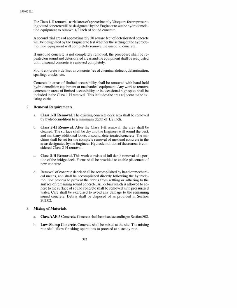
382
650.05 B.1
ForClass 1-H removal, a trial area of approximately 30 square feet represent-ing soundconcretewill bedesignatedby theEngineer to set thehydrodemoli-tion equipment to remove 1/2 inch of sound concrete.
A second trial area of approximately 30 square feet of deteriorated concretewill be designated by the Engineer to test whether the setting of the hydrode-molition equipment will completely remove the unsound concrete.
If unsound concrete is not completely removed, the procedure shall be re-peated on sound and deteriorated areas and the equipment shall be readjusteduntil unsound concrete is removed completely.
Soundconcrete is definedas concrete free of chemical defects, delamination,spalling, cracks, etc.
Concrete in areas of limited accessibility shall be removed with hand-heldhydrodemolition equipment or mechanical equipment. Anywork to removeconcrete in areas of limited accessibility or in occasional high spots shall beincluded in the Class 1-H removal. This includes the area adjacent to the ex-isting curbs.
2. Removal Requirements.
a. Class 1-H Removal. The existing concrete deck area shall be removedby hydrodemolition to a minimum depth of 1/2 inch.
b. Class 2-H Removal. After the Class 1-H removal, the area shall becleaned. The surface shall be dry and the Engineer will sound the deckandmark any additional loose, unsound, deteriorated concrete. Thema-chine shall be set for the complete removal of unsound concrete in theareasdesignatedby theEngineer.Hydrodemolitionof these areas is con-sidered Class 2-H removal.
c. Class 3-HRemoval. This work consists of full depth removal of a por-tion of the bridge deck. Forms shall be provided to enable placement ofnew concrete.
d. Removal of concrete debris shall be accomplished by hand or mechani-cal means, and shall be accomplished directly following the hydrode-molition process to prevent the debris from settling or adhering to thesurface of remaining sound concrete. All debris which is allowed to ad-here to the surface of sound concrete shall be removed with pressurizedwater. Care shall be exercised to avoid any damage to the remainingsound concrete. Debris shall be disposed of as provided in Section202.02.
3. Mixing of Materials.
a. ClassAAE-3Concrete.Concrete shall bemixed according toSection802.
b. Low-SlumpConcrete.Concrete shall be mixed at the site. The mixingrate shall allow finishing operations to proceed at a steady rate.

383
650.05 B.5
4. Placing, Finishing, and Curing Overlay.
a. General.
At longitudinal construction joints, the surface course previously placedshall be sawn to a straight and vertical edge before the adjacent course isplaced.
After the machine finishing has been completed, hand finishing with awood float may be required to produce a tight, uniform surface.
Immediately after finishing, all vertical joints with adjacent concreteshall be sealed by painting with a thinned grout before the curing opera-tion begins.
A drag shall be pulled over the surface in a longitudinal direction whilethe concrete is plastic. It shall be immediately followedwith a transversemetal tine finish as specified in Section 602.03 B.2.a.
b. Special Requirements for Low-Slump Concrete.
Concrete forClass1-Hor2-Hremoval areasmaybeplaced inoneopera-tion.
Where full depth concrete is required, Class AAE-3 or low-slump con-crete may be used. Concrete for the Class 3-H removal areas shall bestruck off at the bottom level of Class 1-H unless the Class 3-H falls en-tirely within a Class 2-H removal area. In that case, the concrete shallmatch the prepared surface of the Class 2-H area. The concrete shall re-ceive the wet cure specified in Section 602.03 F.3 for at least 72 hours,and shall be sandblasted and cleaned before overlaying.
The prepared deck surface shall be dry to permit absorption of the bond-ing grout. All vertical and horizontal surfaces shall receive a thorough,even coating of bonding grout at a controlled rate so the grout does notdry before covering with new concrete.
The concrete shall be screeded to a final grade and consolidated to 98percent of the unit weight using AASHTO T 121.
The surface shall receive a wet cure meeting Section 602.03 F.3 exceptthat the curing period shall be five days. Concrete that is not wet curedwithin 30 minutes after placement shall be removed to the original pre-pared surface and replaced at the Contractor’s expense.
5. Limitations of Operations.
Nopreparationworkwill be alloweduntil the laneor strip is closed for traffic.This lane shall remain closed until the overlay has been completed.
No loads other than equipment needed to remove and replace concrete shallbe permitted on the deck that has undergone preparation before placementand curing of concrete. Mixers shall not be operated on the structure. Equip-
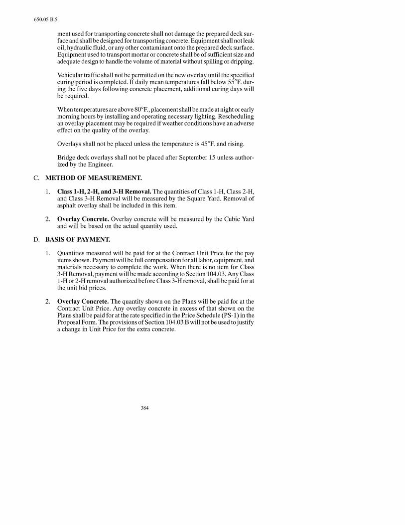
384
650.05 B.5
ment used for transporting concrete shall not damage the prepared deck sur-faceandshall bedesigned for transportingconcrete.Equipment shall not leakoil, hydraulic fluid, or any other contaminant onto the prepared deck surface.Equipment used to transportmortar or concrete shall be of sufficient size andadequate design to handle the volume of material without spilling or dripping.
Vehicular traffic shall not be permitted on the new overlay until the specifiedcuring period is completed. If daily mean temperatures fall below 55°F. dur-ing the five days following concrete placement, additional curing days willbe required.
When temperaturesareabove80°F., placement shall bemadeatnightor earlymorning hours by installing and operating necessary lighting. Reschedulingan overlay placementmay be required if weather conditions have an adverseeffect on the quality of the overlay.
Overlays shall not be placed unless the temperature is 45°F. and rising.
Bridge deck overlays shall not be placed after September 15 unless author-ized by the Engineer.
C. METHOD OF MEASUREMENT.
1. Class 1-H, 2-H, and 3-HRemoval. The quantities of Class 1-H, Class 2-H,and Class 3-H Removal will be measured by the Square Yard. Removal ofasphalt overlay shall be included in this item.
2. Overlay Concrete. Overlay concrete will be measured by the Cubic Yardand will be based on the actual quantity used.
D. BASIS OF PAYMENT.
1. Quantities measured will be paid for at the Contract Unit Price for the payitemsshown.Paymentwill be full compensation for all labor, equipment, andmaterials necessary to complete the work. When there is no item for Class3-HRemoval, paymentwill bemade according toSection 104.03.AnyClass1-H or 2-H removal authorized beforeClass 3-H removal, shall be paid for atthe unit bid prices.
2. Overlay Concrete. The quantity shown on the Plans will be paid for at theContract Unit Price. Any overlay concrete in excess of that shown on thePlans shall be paid for at the rate specified in the Price Schedule (PS-1) in theProposal Form.The provisions of Section 104.03Bwill not be used to justifya change in Unit Price for the extra concrete.

385
SECTION 700MISCELLANEOUS CONSTRUCTION

386
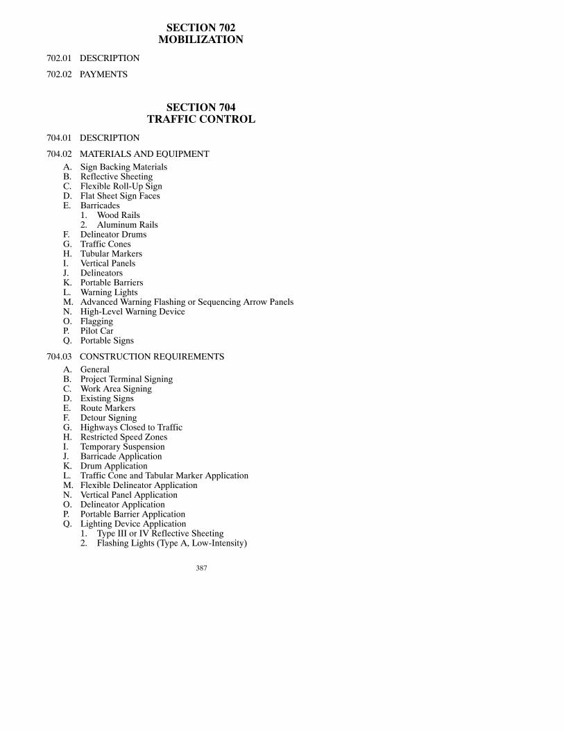
387
SECTION 702MOBILIZATION
702.01 DESCRIPTION
702.02 PAYMENTS
SECTION 704TRAFFIC CONTROL
704.01 DESCRIPTION
704.02 MATERIALS AND EQUIPMENTA. Sign Backing MaterialsB. Reflective SheetingC. Flexible Roll-Up SignD. Flat Sheet Sign FacesE. Barricades
1. Wood Rails2. Aluminum Rails
F. Delineator DrumsG. Traffic ConesH. Tubular MarkersI. Vertical PanelsJ. DelineatorsK. Portable BarriersL. Warning LightsM. Advanced Warning Flashing or Sequencing Arrow PanelsN. High-Level Warning DeviceO. FlaggingP. Pilot CarQ. Portable Signs
704.03 CONSTRUCTION REQUIREMENTSA. GeneralB. Project Terminal SigningC. Work Area SigningD. Existing SignsE. Route MarkersF. Detour SigningG. Highways Closed to TrafficH. Restricted Speed ZonesI. Temporary SuspensionJ. Barricade ApplicationK. Drum ApplicationL. Traffic Cone and Tabular Marker ApplicationM. Flexible Delineator ApplicationN. Vertical Panel ApplicationO. Delineator ApplicationP. Portable Barrier ApplicationQ. Lighting Device Application
1. Type III or IV Reflective Sheeting2. Flashing Lights (Type A, Low-Intensity)

388
3. Flashing Lights (Type B, Hi-Intensity)4. Steady-Burn Lights (Type C)5. Mounting Height of Warning Lights
a. Barricade and Portable Standardsb. Signsc. Vertical Channelizing Devices and Independent Supports
6. Advance Warning Arrow Panels7. Floodlights
R. High-Level Warning DeviceS. Obliteration of Pavement MarkingT. Construction Zone MarkingU. Traffic Control Personnel
1. Traffic Control Supervisora. Qualificationsb. Dutiesc. Traffic Control Course
2. WatchpersonsV. Emergency ControlW. Maintenance of Traffic Control DevicesX. FlaggingY. Pilot CarZ. Flag Application
704.04 METHOD OF MEASUREMENT
704.05 BASIS OF PAYMENT
SECTION 706FIELD LABORATORY
706.01 DESCRIPTION
706.02 REQUIREMENTSA. Type A, Field LaboratoryB. Type B, Field LaboratoryC. Type C, Field Laboratory
706.03 METHOD OF MEASUREMENT
706.04 BASIS OF PAYMENT
SECTION 708EROSION CONTROL
708.01 DESCRIPTION
708.02 SEEDING, SODDING, AND MULCHINGA. DescriptionB. Materials
1. Seedinga. Generalb. Seed Testingc. Labeling

389
d. Seed Classese. Fertilizer Requirements
2. Soddinga. Generalb. Peat Sodc. Sampling, Testing, and Certification
3. Mulchinga. Hydro Mulchingb. Grass Hay or Straw Mulchc. SS-1 Emulsion
C. Construction Requirements1. Seeding
a. Generalb. Topsoilc. Types of Seedbed Preparationd. Seasonal Limitationse. Seeding Equipment Requirementsf. Fertilizerg. Reseeding and Repairh. Temporary Care
2. Soddinga. Preparation of the Earth Bedb. Placing the Sodc. Staking the Sodd. Clean-Upe. Fertilizerf. Care and Maintenanceg. Acceptance
3. Hydro-Mulch4. Grass, Hay, or Straw Mulch
a. Generalb. Equipmentc. Applicationd. Anchoringe. Temporary Maintenance
D. Method of MeasurementE. Basis of Payment
708.03 EROSION CONTROL BLANKET AND TURF REINFORCEMENTMAT
A. DescriptionB. MaterialsC. Construction Requirements
1. Wood Excelsior or Fiber Mat2. Erosion Control Fabric3. Fiberglass Roving4. Repair of Soil Retention Blanket
D. Method of MeasurementE. Basis of Payment
708.04 RIPRAP AND AGGREGATE CUSHIONA. DescriptionB. Materials
1. Wire Mesh2. Grout
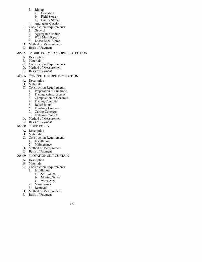
390
3. Riprapa. Gradationb. Field Stonec. Quarry Stone
4. Aggregate CushionC. Construction Requirements
1. General2. Aggregate Cushion3. Wire Mesh Riprap4. Loose Rock Riprap
D. Method of MeasurementE. Basis of Payment
708.05 FABRIC FORMED SLOPE PROTECTIONA. DescriptionB. MaterialsC. Construction RequirementsD. Method of MeasurementE. Basis of Payment
708.06 CONCRETE SLOPE PROTECTIONA. DescriptionB. MaterialsC. Construction Requirements
1. Preparation of Subgrade2. Placing Reinforcement3. Composition of Concrete4. Placing Concrete5. Relief Joints6. Finishing Concrete7. Curing Concrete8. Tests on Concrete
D. Method of MeasurementE. Basis of Payment
708.08 FIBER ROLLSA. DescriptionB. MaterialsC. Construction Requirements
1. Installation2. Maintenance
D. Method of MeasurementE. Basis of Payment
708.09 FLOTATION SILT CURTAINA. DescriptionB. MaterialsC. Construction Requirements
1. Installationa. Still Waterb. Moving Waterc. Work Area
2. Maintenance3. Removal
D. Method of MeasurementE. Basis of Payment
391
708.10 STABILIZED CONSTRUCTION ACCESSA. DescriptionB. Materials
1. Aggregate2. Geotextile Fabric
C. Construction RequirementsD. MaintenanceE. Method of MeasurementF. Basis of Payment
SECTION 709GEOTEXTILE FABRICS
709.01 DESCRIPTION
709.02 MATERIALS
709.03 CONSTRUCTION REQUIREMENTSA. GeneralB. Geotextile Separation FabricC. Filter Fabric (Underdrains)D. Filter Fabric (Riprap)E. Geotextile Reinforcement Fabric
709.04 METHOD OF MEASUREMENT
709.05 BASIS OF PAYMENT
SECTION 710TEMPORARY BYPASS
710.01 DESCRIPTION
710.02 CONSTRUCTION REQUIREMENTS
710.03 METHOD OF MEASUREMENT
710.04 BASIS OF PAYMENT
SECTION 714CULVERTS, STORM DRAINS, EDGE DRAINS,
AND UNDERDRAINS
714.01 DESCRIPTION
714.02 MATERIALSA. Culverts and Storm DrainsB. UnderdrainsC. Bridge Approach DrainsD. Edge Drains
714.03 CONSTRUCTION REQUIREMENTS
392
A. Culverts and Storm Drains1. Excavation2. Bedding3. Handling and Assembly4. Laying Pipe5. Joining Pipe6. Relaid Pipe7. Backfilling for Pipe Installed in Embankments8. Backfilling for Pipe Installed in Trenches9. Corrugated Polyethylene Pipe10. Connection to Manholes, Inlets, and Pipes
B. Smooth Wall Steel Pipe CulvertC. UnderdrainsD. Bridge Approach DrainsE. Edge DrainsF. Drainage
714.04 METHOD OF MEASUREMENT
714.05 BASIS OF PAYMENT
SECTION 720MONUMENTS AND RIGHT OF WAYMARKERS
720.01 DESCRIPTION
720.02 MATERIALS
720.03 CONSTRUCTION REQUIREMENTS
A. MonumentsB. Right of Way Markers
720.04 METHOD OF MEASUREMENT
720.05 BASIS OF PAYMENT
SECTION 722MANHOLES, CATCH BASINS, AND INLETS
722.01 DESCRIPTION
722.02 MATERIALS
722.03 CONSTRUCTION REQUIREMENTS
A. ExcavationB. Brick Masonry ConstructionC. Precast Concrete Masonry UnitsD. Precast RCP Manholes, Inlets, and Catch BasinsE. Concrete Construction (Cast-in-Place)F. Concrete Base (Pre-cast or Cast-in-Place)G. Pipe ConnectionsH. ReinforcementI. Placing Castings
393
J. BackfillK. CleaningL. Adjustments to Existing Units
722.04 METHOD OF MEASUREMENT
722.05 BASIS OF PAYMENT
SECTION 724WATER MAINS, WATER LINES, AND SEWER LINES
724.01 DESCRIPTION
724.02 MATERIALSA. PipesB. Joints and FittingsC. Rubber GasketsD. Gate ValvesE. Butterfly ValvesF. Valve BoxesG. HydrantsH. Tapping Saddle and Tapping Valve or Tapping Sleeve and Tapping ValveI. AggregatesJ. ConcreteK. Corporation Stops (Cocks), Curb Stops, and Curb Boxes
724.03 CONSTRUCTION REQUIREMENTSA. GeneralB. Excavation and Trenching
1. Excavation2. Bedding3. Backfilling
C. Water Main Requirements1. Laying Water Mains2. Testing and Disinfecting Lines3. Thrust Blocks4. Hydrants5. Reset Hydrant6. Backfill7. Marking Tape
D. Water and Service Lines1. General2. Laying Water Line3. Testing
E. Sanitary Sewer Pipe Requirements
724.04 METHOD OF MEASUREMENT
724.05 BASIS OF PAYMENT
SECTION 740DAMPPROOFING AND FABRIC WATERPROOFING
740.01 DESCRIPTION

394
740.02 MATERIALS
740.03 CONSTRUCTION REQUIREMENTS
A. GeneralB. DampproofingC. Fabric WaterproofingD. Black Polyethylene Membrane
740.04 METHOD OF MEASUREMENT
740.05 BASIS OF PAYMENT
SECTION 744INSULATION BOARD (POLYSTYRENE)
744.01 DESCRIPTION
744.02 MATERIALS
744.03 CONSTRUCTION REQUIREMENTS
A. Subgrade PreparationB. InstallationC. Cover MaterialD. Traffic
744.04 METHOD OF MEASUREMENT
744.05 BASIS OF PAYMENT
SECTION 748CURB AND GUTTER
748.01 DESCRIPTION
748.02 MATERIALS
748.03 CONSTRUCTION REQUIREMENTS
A. Cast-in-Place Concrete Curb and Gutter1. Equipment2. Excavation3. Base4. Mixing, Placing, and Finishing5. Use of Water6. Joints and Joint Sealing7. Curing8. Backfill9. Operational Limits
B. Precast Concrete Curbing1. Excavation2. Base3. Installation4. Surface Finish5. Joints

395
6. BackfillC. Bituminous Curbing
1. Excavation2. Base3. Preparation of Bed4. Placing5. Painting and Sealing6. Backfill
748.04 METHOD OF MEASUREMENT
748.05 BASIS OF PAYMENT
SECTION 750SIDEWALKS AND DRIVEWAYS
750.01 DESCRIPTION
750.02 MATERIALS
750.03 CONSTRUCTION REQUIREMENTS
A. FormsB. ExcavationC. BaseD. Placing ConcreteE. FinishingF. Use of WaterG. JointsH. CuringI. BackfillJ. Operational LimitsK. Detectable Warning Panels
750.04 METHOD OF MEASUREMENT
750.05 BASIS OF PAYMENT
SECTION 752FENCING -- INSTALLATION AND RESETTING
752.01 DESCRIPTION
752.02 MATERIALS
752.03 CONSTRUCTION REQUIREMENTS
A. GeneralB. Installing Line PostsC. Corner and Brace AssembliesD. Installing Fence Wire
1. Barbed Wire and Woven Wire2. Chain Link Fence
E. GatesF. Resetting Fences

396
752.04 METHOD OF MEASUREMENT
752.05 BASIS OF PAYMENT
SECTION 754HIGHWAY SIGNS
754.01 DESCRIPTION
754.02 MATERIALSA. GeneralB. ConcreteC. Reinforcing SteelD. DelineatorsE. Hardware and FittingsF. Overhead Sign StructuresG. Posts
754.03 CONSTRUCTION REQUIREMENTSA. Locating and Positioning Signs and Sign StructuresB. Sign Fabrication
1. General2. Fabrication of Sign Backing3. Cleaning and Processing4. Fabrication of Flat Sheet Signs5. Fabrication of Panel Signs6. Date of Fabrication
C. Packaging, Labeling, Handling, and ShippingD. Label (Handling, Storage, and Installation Instructions)
1. Loading on Vehicles2. Storage at Job Site3. Installation
E. Erection of Sign Supports and Delineators1. General2. Delineator Posts3. Anchor for Telescoping Perforated Tubes and Flange Channel Sup-
ports4. Tubular Sign Supports5. Overhead Sign Structures6. Splicing7. W-Shaped Sign Supports
F. Mounting Flat Sheet Signs Type III A and III B SheetingG. Removing and Resetting Signs and SupportsH. Remove Sign FoundationsI. Revise Fuse JointsJ. Overlay Panel Sign RefacingK. Auxiliary Signs
754.04 METHOD OF MEASUREMENT
754.05 BASIS OF PAYMENT
SECTION 762PAVEMENT MARKING
762.01 DESCRIPTION

397
762.02 MATERIALS
762.03 EQUIPMENT
A. Paint ApplicatorB. Grooving Equipment
762.04 CONSTRUCTION REQUIREMENTS
A. GeneralB. Pavement Surface Preparation
1. General2. Plastic Pavement Marking Film3. Preformed Patterned Pavement Marking Film4. Pavement Marking Paint5. Short-Term Pavement Marking
C. Traffic Control1. Signing2. Traffic Movement3. Time Period for Control4. Operational Precautions
D. Pavement Marking Application1. Pavement Marking Paint and Glass Beads
a. Method of Applicationb. Application Dates and Temperaturec. Rate of Applicationd. Short-Term Pavement Markinge. Short-Term Pavement Marking-Seal Coat Projectsf. Tolerance
2. Plastic Pavement Marking Filma. Generalb. Plastic Pavement Marking Film Applicationc. Short-Term Pavement Marking
3. Preformed Patterned Pavement Marking Film4. Pavement Marking Sheeting (Pressure Sensitive)5. Raised Pavement Markers6. Epoxy Paint and Glass Beads
E. Inspection and Acceptance1. General2. Maintenance of Short-Term Pavement Marking3. Pay Adjustment for Short-Term Pavement Markings4. Acceptance of Epoxy Paint Pavement Marking
762.05 METHOD OF MEASUREMENT
762.06 BASIS OF PAYMENT
SECTION 764GUARDRAIL
764.01 DESCRIPTION
764.02 MATERIALS
764.03 CONSTRUCTION REQUIREMENTS
A. General

398
B. Cable GuardrailC. W-Beam GuardrailD. Removal of Guardrail
1. Cable Guardrail2. W-Beam Guardrail3. Box Beam Guardrail4. End Treatment and Transition5. Miscellaneous Hardware6. Anchors7. Disposal of Unsalvageable Materials
E. Reset Cable GuardrailF. Reset W-Beam GuardrailG. Reset Box Beam GuardrailH. Completion Requirements
764.04 METHOD OF MEASUREMENT
764.05 BASIS OF PAYMENT
SECTION 766MAILBOX ASSEMBLIES
766.01 DESCRIPTION
766.02 MATERIALS
766.03 CONSTRUCTION REQUIREMENTS
766.04 METHOD OF MEASUREMENT
766.05 BASIS OF PAYMENT

399
704.01
SECTION 702MOBILIZATION
702.01 DESCRIPTION.
This work consists of preparatory work and operations, including: movement of per-sonnel, equipment, and supplies, establishment of offices, Contractor’s buildings, andfacilities necessary for work on the Project; and all other work and operations whichmust be performed, or costs incurred, before beginning work on the Project site.
702.02 PAYMENTS.
PartialContract paymentswill bemade forMobilizationusing the followingschedule:
When the listedpercentageof theoriginalContract amount is earned, thepercentageofthe amount bid for Mobilization, or the percentage of original Contract amount,whichever is less, will be paid.
Amount Earned of: Pay Lesser of:
Total Mobilization Total ContractContract Bid Amount Amount
5% 25% 2-1/2%10% 50% 5%50% 100% 7-1/2%75% 100% 10%
Upon completion of all work on the Project, payment of any amount bid forMobiliza-tion in excess of 10 percent of the original Contract amount will be paid.
SECTION 704TRAFFIC CONTROL
704.01 DESCRIPTION.
Thisworkconsistsof furnishing, installing, andmaintainingall required traffic controldevices according to the traffic control plan details shown on the Plans. This includes

400
704.01
Specificationsproviding forwatchpersons, flaggers, pilot cars, and necessaryprecau-tions for protecting the public, the workers, and the work.
All traffic control devices and their placement shall meet the standards and require-ments of the Manual on Uniform Traffic Control Devices for Streets and Highways(MUTCD) and the Standard Highway Signs, published by the Federal Highway Ad-ministration. All new and used Category I and II Traffic Control Devices shall meetNational Cooperative Highway Research Program 350 (NCHRP Report 350) Guide-lines.
At the Pre-ConstructionConference theContractor shall provide theEngineer aLetterof Compliance stating that all Category I and II devices are NCHRP Report 350 ap-proved. The Letter of Compliance shall also include approved shop drawings of thesigns and devices.
704.02 MATERIALS AND EQUIPMENT.
A. Sign Backing Materials. Materials for sign backing shall be aluminum, steel,plywood, or plastic of the size and thickness shown on the Standard Drawings.Aluminumor steel backing shallmeet and beprocessed according toSection754.Plywood backing shall be of exterior grade or be overlaid with a plastic coating,and processed using recommendations of the reflective sheeting manufacturer.Plastic backing shall be processed using recommendations of the reflective sheet-ing manufacturer.
B. Reflective Sheeting. Orange diamond-shaped, rectangular, and square signsshall be faced with Wide Angle Prismatic Fluorescent Retroreflective Sheetingmeeting Section 894.02 G. Barricades and vertical panels shall be Wide AnglePrismatic Retroreflective Sheeting meeting Section 894.02 F. Flexible reflectivesheeting, Type IIIC, shall be usedondrums, cones, flexible delineators, and tubularmarkers. All remaining signs and sign backgrounds shall be faced with WideAngle Prismatic Retroreflective Sheeting meeting Section 894.02 F.
C. Flexible Roll-Up Sign. The flexible roll-up sign shall be mounted in a sturdyframe to keep the sign flat and in proper position for viewing by themotorist. Theframeshall be attached toaportable stand for placementon the roadbed.Thestandshall be weighted or designed to provide stability against wind. Flexible roll-upsigns shall be fabricated to meet Section 894.02 E.2.
D. Flat Sheet Sign Faces.All flat sheet sign faces, except for flexible roll-up signsas provided above, shall be fabricated to meet Section 894.01.
E. Barricades.Barricades shall be constructed of light weightmaterials. They shallbe the type and length shown on the Standard Drawings.
Both sides of the barricade rail surface shall be coveredwith reflective sheeting asspecified.
1. Wood Rails.Woodrails shallmeet theStandardRulesof theAmericanLum-ber Standards. Application of reflective sheeting directly onwood rails shallbemadeonlyafter all edgesandsurfaceshavebeenproperly sanded, cleaned,sealed, resanded, andpaintedwithaprimecoat.Thepaintedsurfaceonwhichthe reflective sheeting is applied shall be treated as specified by the reflective
401
704.02 J
sheeting manufacturer. In lieu of treating the painted surface to receive thereflective sheeting, sheet aluminum having a minimum thickness of 0.040inchesmaybe attached to the barricade railswith non-rust fasteners. The alu-minumsheet shall be fabricated anddegreased asprovided inSection754be-fore applying reflective sheeting.
2. Aluminum Rails.Aluminumrails shall be an extrusionof the size and shapeshown on the Standard Drawings and shall meet ASTMDesignation B 221,Alloy 6063-T6. They shall be fabricated and degreased as provided in Sec-tion 754 before applying reflective sheeting.
F. Delineator Drums.Drumsshall be approximately36 inches inheight andamini-mumof 18 inches indiameter at the top.They shall be constructedof durable plas-tic with horizontal, circumferential, orange and white reflectorized stripes asshown on the Standard Drawings. The reflectorized stripes shall be fabricatedfromType III C, Type IV, orWide Angle Prismatic flexible reflective sheeting asprovided in Section 894.02. Delineator drums shall beweightedwith sand placedat the bottomof the drumor constructed so that they can not be blown over or dis-placed bywindor passing traffic, and donot create a hazard if accidentally struck.
G. Traffic Cones. The cones shall be orange in color, shall be a minimum of 28inches in height with a broadened base, and fabricated from materials that with-stand impact. For nighttime use, cones shall have a minimum 6-inch wide whiteflexible reflectorized band placed a minimum of 3 inches; but not more than 4inches from the top.An additional 4-inchwhite reflectorized band shall be placedaminimum of 2 inches below the 6-inch band. The cones shall be weighted at thebase to prevent overturning by the wind. The reflectorized band shall be fabri-cated fromType III C, Type IV orWideAngle Prismatic flexible reflective sheet-ing as provided in Section 894.02.
H. Tubular Markers and Flexible Delineators. These devices shall be used tochannelize traffic.
1. TubularMarkers.Tubularmarkers shallmeet thedimensions, color config-uration, and installation details as shown on the Standard Drawings.
2. Flexible Delineators. The flexible delineators shall be installed in the loca-tions shown on the plans. The posts shall be resilient and be orange in color.The delineator posts shall be made of PVC or polyethylene and shall be pre-approved for use by the Design Division. Posts currently approved are Ser-vices andMaterial Co. Inc., Deluxe delineator post and SafetyGuide’s Traf--Flex Post or Flex Stake.
The post shall have 4-inch wide white bands as shown on the plans. The re-flective intensity of the bands shallmeet the requirements of Type III B, TypeIIIC, orWideAnglePrismatic flexible reflective sheetingasprovided inSec-tion 894.02
I. Vertical Panels.The vertical panels shall meet the dimensions, striping configu-ration, andcolors shownon theStandardDrawings.Thepanels shall be fabricatedas specified for flat sheet signs in Section 754.
J. Delineators.Each delineator shall consist of an acrylic plastic or reflective sheet-ing reflector mounted on a post support according to the Standard Drawings.
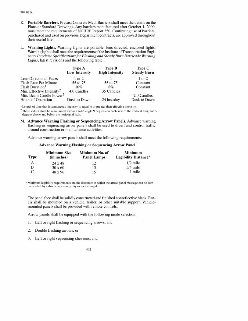
402
704.02 K
K. Portable Barriers. Precast Concrete Med. Barriers shall meet the details on thePlans or Standard Drawings. Any barriers manufactured after October 1, 2000,must meet the requirements of NCHRP Report 350. Continuing use of barriers,purchased and used on previous Department contracts, are approved throughouttheir useful life.
L. Warning Lights. Warning lights are portable, lens directed, enclosed lights.Warning lights shallmeet the requirementsof the InstituteofTransportationEngi-neers Purchase Specifications for Flashing and Steady Burn BarricadeWarningLights, latest revisions and the following table:
Type A Type B Type CLow Intensity High Intensity Steady Burn
Lens Directional Faces 1 or 2 1 1 or 2Flash Rate Per Minute 55 to 75 55 to 75 ConstantFlash Duration1 10% 8% ConstantMin. Effective Intensity2 4.0 Candles 35 CandlesMin. Beam Candle Power2 2.0 CandlesHours of Operation Dusk to Dawn 24 hrs./day Dusk to Dawn1Length of time that instantaneous intensity is equal to or greater than effective intensity.2These values shall be maintained within a solid angle 9 degrees on each side of the vertical axis, and 5degrees above and below the horizontal axis.
M. Advance Warning Flashing or Sequencing Arrow Panels. Advance warningflashing or sequencing arrow panels shall be used to divert and control trafficaround construction or maintenance activities.
Advance warning arrow panels shall meet the following requirements:
Advance Warning Flashing or Sequencing Arrow Panel
TypeMinimum Size(in inches)
Minimum No. ofPanel Lamps
MinimumLegibility Distance*
ABC
24 x 4830 x 6048 x 96
121315
1/2 mile3/4 mile1 mile
*Minimum legibility requirements are the distances at which the arrow panel message can be com-prehended by a driver on a sunny day or a clear night.
The panel face shall be solidly constructed and finished nonreflective black. Pan-els shall be mounted on a vehicle, trailer, or other suitable support. Vehicle-mounted panels shall be provided with remote controls.
Arrow panels shall be equipped with the following mode selection:
1. Left or right flashing or sequencing arrows, and
2. Double flashing arrows, or
3. Left or right sequencing chevrons, and
403
704.03 A
4. Caution.
Automatic light dimming controls capable of reducing rated lampvoltage amini-mum of 50 percent shall be provided on each arrow panel. The dimming shall becontrolled by a photoelectric cell which activates at sunup and sundown. Theflashing rate of the lamps shall not be less than 25 nor more than 40 flashes perminute.
Minimum lamp “on” time shall be 50 percent for the flashing arrow and 25 per-cent for the sequential chevron.
The arrow panel lamps or lenses shall be recess-mounted or alternately equippedwith an upper hood of not less than 180 degrees. The color of the light emittedshall be yellow.
N. High-Level Warning Device. This warning device consists of a minimum of 3flags and, when specified, a Type B high-intensity flashing light. The distancefrom the roadway to the bottomof the flasher lens or the lowest point of all 3 flagsshall be at least 8 feet. The flags shall be aminimumof 16 inches square and shallbe orange or fluorescent red-orange in color.
O. Flagging.STOP/SLOWSign Paddles shallmeet the details specified in the Stan-dard Drawings. The paddle shall be fastened to a rigid handle of five to eight feetin length. The paddle shall be fabricated from light semirigidmaterial, and be oc-tagonal in shape. To improve conspicuity, the paddles may be supplemented byone or two symmetrically positioned, alternately flashing, white high-intensitylamps on each side.
When nighttime flagging is required, sufficient auxiliary lighting shall be used toilluminate the flagging station. This lighting shall be supplied by the contractorand set up in such amanner so that drivers are not blinded by it. A flashlightwith ared transparent glowcone, reflectorized clothing, and a reflectorized stop-slowpaddle are required for nighttime flagging operations.
P. Pilot Car. The pilot car shall be a pickup truck or automobile. A 36-inch by18-inch sign reading “PilotCar FollowMe,” as detailed in theStandardDrawingsshall be mounted on the rear of the vehicle and an oscillating or rotating yellowflashing light shall be mounted on the roof of the vehicle.
Q. Portable Signs.All portable signmounts that are in place longer than 24 hours orare in place after sunset shall be perpendicular to the ground.
704.03 CONSTRUCTION REQUIREMENTS.
A. General. The Contractor shall furnish, install, and maintain all required trafficcontrol devices, and shall providewatchpersons and flaggers as necessary to pro-tect the work and to ensure public and workers’ safety. All required control de-vices shall be available for installationwhenneededand shall bemaintained, relo-cated, covered, or removed as necessary. Standards for flagging shall be as speci-fied in Section 704.03 X.
When work zone signs placed as shown on the Standard Drawings interfere withpermanent signs, the work zone signs shall be moved to locations that afford thebest results. Messages shall be varied as required.

404
704.03 A
The Contractor is responsible for providing the required traffic control to ensurepublic and worker safety. If the Contractor has not furnished, installed, located,maintained or removed one or more traffic control devices as required, the Engi-neer may:
1. Apply a contract price reduction of $500 per day if deficiencies are not cor-rected within a 24-hour period after notification.
2. Without notification, have the deficiencies corrected by another contractorand deduct the cost of the work frommonies due or to become due the Con-tractor.
3. Direct work to cease until the deficiencies have been corrected.
Traffic control devices shall be operated only as long as they are needed. Onlythose devices that apply to existing conditions shall be in place. Construction signbases without attached signs shall be marked so they are visible.
The traffic control devices shall have breakaway supports that meet the require-ments of the AASHTORoad-side Design Guide Chapter 4 Section 4.1. All signson fixed supports shall be placed on breakaway supports, unless they are locatedbehind a barrier or crash cushion. The Contractor shall provide documentationshowing the requirements are being met for any sign supports used that do notcomply with the Department’s Standard Drawings.
Barricade rails and panels with stripes which begin at the upper right side andslopedownward to the lower left side aredesignatedas“right”panels andare tobeusedon the right sideof a traffic lane. Stripeswhichbegin at the upper left side andslopedownward to the lower right sidearedesignatedas“left”panels andare tobeused on the left side of a traffic lane.
B. Project Terminal Signing.Beforework is started, the required traffic controlde-vices shall be erected at each end of the project and at various locationswithin theProject as shown on the traffic control Plan drawings. These control devices shallremain in place and be maintained for the duration of the Project. The Engineermay direct their removal during winter or other lengthy periods of suspension.
C. Work Area Signing. Appropriate traffic control devices as shown on the trafficcontrol Plan drawings shall be erected andmaintained for each type of work arearequired by the operations.When no details are provided for the particular type ofconstruction situation involved, traffic control devices shall be installed accord-ing to theMUTCD or as directed by the Engineer. No construction work shall bestarted until the proper traffic control devices for the work area are in place. If theContractor’s construction operations or sequence requires additional signing,flaggers shall be furnished at theContractor’s expense or construction operationsshall be suspended in that area until the condition is corrected and the requiredsigns have been installed.
When traffic is carried through the construction area, two-way traffic shall bemaintainedwhen practicable. One-way traffic shall be directed by flagpersons ormaintained under control of an approved traffic signal system.All signs andothercontrol devices shall indicate actual conditions and shall be relocated, removed,or changedas conditions require. Signsnecessaryonlyduringhourswhenwork is
405
704.03 I
actually being performed shall be removed or completely coveredwhen noworkis in progress.
Portable signs shall be used when construction operations in an area are tempo-rary. Temporary operations are those that can generally be completed in five daysor less. If unforeseen circumstances occur, such as equipment breakdown, rain,subgrade failures, etc., time will not accrue towards the five-day period.
Whenportable signsareused, they shall beplacedon theshoulder oroutsideof thetraveled lanewhere theydonot pose a hazard to traffic. Theportable signs shall beplaced in clear view without any sight obstructions to oncoming traffic. Whenportable signs are not in use, they shall be removed, moved to a minimum of 45feet from the edge of the traveled lane, or laid down on the inslope. Signs laid onthe inslope shall have stand bases constructed so the signs andbases can beplacedflat with no portions of the sign or base projecting upward from the inslope morethan 6 inches. When it is necessary to place a temporary sign on a paved surface,the sign may be mounted on portable supports for longer than five days.
The portable signs support assembly mounted on trailers shall meet the require-ments as specified above for portable signs except as follows. The portable signsmounted on trailers that have passed the crash test required of NCHRPReport 350,as approved by the FHWA, shall be used.When portable signsmounted on trailersare used, they shall be removed, moved aminimum of 45 feet from the edge of thetraveled way, or covered so the sign message cannot be read by approaching ve-hicles.
D. Existing Signs.Existing regulatory traffic signswhichmust bemoved to accom-modate construction shall be immediately reset.
The cost to remove and reset existing traffic signs to accommodate constructionshall be included in the price bid for other items.
E. Route Markers.Routemarker signs required for the Project and for Contractor-maintained detours will be furnished by the Department and shall be installed bythe Contractor on supports furnished by and at the Contractor’s expense.
F. Detour Signing. The Contractor shall furnish, install, and maintain all trafficcontrol devices for detours.
G. Highways Closed to Traffic.When a detour is provided and traffic is not main-tained through the construction area, necessary access to property abutting theProject shall be provided by constructing and maintaining temporary roads andapproaches fromthenearest crossroad.Traffic shall notbe routedover detoursnotprovided in the Contract documentswithoutwritten authorization from the Engi-neer.
H. Restricted Speed Zones.Restricted speed zones and the speed limit to be postedfor such zoneswill be designated in the Contract documents or determined by theEngineer.
I. Temporary Suspension.Duringa temporary suspensionofwork, theContractoris responsible for maintaining and protecting traffic. When operations are sus-pended for the winter or are indefinitely suspended for reasons beyond the Con-

406
704.03 I
tractor’s control, the roadwayand the traffic control deviceswill bemaintainedbyand at the Department’s expense.
Before suspending operations for the winter, adequate approaches shall be con-structed to all crossroads or intersecting roadswhich have been disturbed by con-struction operations. Access to the roadway from abutting property shall also beprovided. Warning signs, barricades, and other traffic control devices shall beerected (or existing devices removed) as directed by the Engineer. Resetting ofsigns removed because of a winter suspensionwill not bemeasured for payment.
J. Barricade Application.Type I orType II barricades shall beused as shown in thetraffic control plan details where traffic is maintained through the constructionarea. Theymay be used singly or in groups to mark a specific hazard, or used in aseries to channelize traffic and shall not be set parallel to traffic. On high-speedroads or in situations where barricades may be overturned in the wind, the barri-cades shall be stabilized with sandbags placed on the lower parts of the frame orstays.
When a section of road is closed to traffic, Type III barricades shall be erected atthe points of closure. They shall extend completely across the roadway and shoul-ders or fromcurb to curb.Where provisionmust bemade for access of equipmentand authorized vehicles, the Type III barricades shall be provided with gates ormovable sections that can be closedwhenwork is not in progress, or with indirectopenings that discourages public entry. Where access is provided through theType III barricade, an employee shall be designated to assure proper closure at theend of each working day.
When a road or street is closed, but access to local traffic must be furnished, theType III barricades shall be arranged to permit local use but discourage throughtraffic. A signwith the appropriate legend concerning use by local traffic shall beinstalled.
Type III barricades shall be installed at the beginning and end of the project whenso indicated in the Contract documents and shall not be placed parallel to traffic.
The required warning signs shall be mounted above the barricades.
If the construction zone encroaches onto sidewalks or crosswalks andpedestrianscannot be diverted to other walkways, barricades may be used to define the path.
K. DrumApplication. Drums shall be used to channelize or delineate traffic flow,and may be used singly or in groups to mark specific hazards. When drums areplaced in the roadway, advance warning signs are required.
L. Traffic Cone and Tubular Marker Application. Traffic cones and tubularmarkers used to channelize traffic shall have adequate stability to prevent over-turning or displacement bywind. Additional weightingmay be required but shallnot be so heavy to cause a hazard if struck.
M. Flexible Delineator Application. The delineator base shall be attached to thepavement as shown on the Plans. The Contractor shall maintain the delineatorsuntil they are removed. The delineators shall be removed as soon as the new road-way is opened to traffic. The flexible delineators shall remain the property of theContractor.

407
704.03 Q
If the Contractor uses a two-sided delineator, the delineator shall have the wideside towards traffic. If the delineator is to be seen by side traffic, an additional de-lineator shall have the wide side placed facing the side traffic. The side traffic de-lineators shall not be paid for, but shall be included to the price bid for “FlexibleDelineators.”
If theContractor uses thebutyl pad for attaching the flexibledelineator toconcreteroadways, the contractor shall remove the butyl pad down as close as possible tothe pavement using a mechanical scraper such as a loader-type machine with abucket.
All costs for providing, installing, maintaining, and removing the flexible delin-eators with butyl pad when used shall be included in the unit price bid for “Flex-ible Delineators.”
N. Vertical Panel Application. Vertical panels shall be used as channelizing de-vices, warning devices, or windrow markers. Vertical panels shall be faced onboth sides.
O. Delineator Application.Delineators shall be used in construction areas for guid-ance, to indicate roadway alignment, and to outline the required vehicle path. De-lineators shall not be used as warning devices and, when used in a constructionzone, shall be combined with approved warning devices.
Delineators shall bemounted on supports so the reflector is 4 feet above the road-way edge. White reflectors shall be used for delineators installed along the rightside of the street or highway. Yellow reflectors shall be used for delineators in-stalled along the left edge of divided streets, divided highways, and one-wayroads.
Delineator spacing shall be as indicated on the traffic control plan sheets. Alongroadway curves, delineators shall be spaced so that several delineators are alwaysvisible to the driver.
P. Portable Barrier Application. Traffic control plan sheets may require, or theContractor may elect to use, portable barriers to separate the work area from thetraffic area. For nighttime use, the barriers shall be supplemented by standard de-lineators or channelizing markings or devices.
When specified, warning lights shall be installed on continuous barriers. The firsttwowarning lights on each side of the roadway shall be TypeA flashers, and sub-sequent lights on the barrier shall be Type C steady burn lights.
TheContractor shall furnish, install,maintain, and removebarriermarkers as spe-cified in thePlans. The costs shall be included in te price bid for “PrecastConcreteMedian Barriers -- State Furnished” or “Precast Concrete Median Barriers.”
The ends of the barrier shall be protected by crash cushions or by flaring the barrierends away from the traveled way as shown in the Contract.
Q. Lighting Device Application.Lighting devices shall be provided as required onthe traffic control plan sheets to supplement signs, barricades, and other trafficcontrol devices.

408
704.03 Q.1
1. Type III or IV Reflective Sheeting. Flashing lights and steady burn lightson signs, drums, vertical panels, and barricades are not required whenType III, Type IV, or wide angle prismatic reflective sheeting is used.
2. Flashing Lights (Type A, Low-Intensity). Type A low-intensity flashersshall be used to warn drivers that they are approaching or traveling in a haz-ardous area.
3. Flashing Lights (Type B, High-Intensity). Traffic control plan sheets re-quire installation of high-intensity flashers at extremely hazardous site con-ditions. The high-intensity flashers shall be operated 24 hours per day.
4. Steady-Burn Lights (Type C). The steady-burn warning lights shall beused to delineate the edges of the traveled way on detour curves, on lanechanges, and along tapers. Spacing of steady-burn lights shall be as indicatedon the traffic control plan sheets.
5. Mounting Height of Warning Lights. The mounting height of warninglights shall be as follows:
a. Barricade and Portable Standards. A minimum height of 36 inchesfrom the bottom of the lens to the roadway.
b. Signs.The bottomof the light housing shall not be less than 2 inches normore than 12 inches above the top of the sign.
c. Vertical ChannelizingDevices and Independent Supports. The lightshall be at least 4 feet and not more than 5 feet above the pavement.
6. Advance Warning Arrow Panels. The sequencing arrow panels shall beused to provide advance warning and directional information to assist in di-vertingandcontrolling traffic aroundconstructionactivitiesbeingconductedon or adjacent to the traveled way. Other traffic control devices may be re-quired in conjunctionwith the sequencing arrowpanel.During nighttimeop-erationof the flashingarrowpanels, the lampsshall be automaticallydimmedto 50 percent of the output.
7. Floodlights. If construction activities are performed at night, floodlightingshall beprovided for the constructionarea and flagger stations.The areamustbe adequately illuminated without creating glare in the eyes of drivers.
R. High-Level Warning Device.High-level warning devices shall be used to sup-plement other controls and devices and shall be required in urban high-densitytraffic situations.
S. Obliteration of Pavement Marking.
1. Removal of existingmarking and installation of short-termmarking shall beas shown on the traffic control plan sheets. Inappropriate existing markingsshall be removed and the new delineation placed before opening the affectedlane or lanes to traffic.
Removal of pavementmarkings shall not permanently damage the surface ortexture of the pavement. Where blast cleaning is used for removal of mark-

409
704.03 U.1.b.(3)
ings or other objectionable material, the sand or other blast material left onthe pavement shall be removed immediately.
2. Painting over or masking existing markings shall be allowed only whenindicated in thePlans.Obliterationof thepavementmarkingsbyuseofgrind-ingor a sandblastingmethodwill not be allowedwhenpaintingormaskingofexisting pavement markings is indicated in the Plans.
Paint shall be mixed so as to closely approximate the color of the in-placepavement. Masking shall be done through the use of removable, non-reflective, preformed tape that minimizes contrast with the pavement.Whenexistingmarkings are covered rather than obliterated, the cover shall overlapthe existing marking by 1 inch on each side.
T. Construction Zone Marking. Yellow short-term marking shall be used to de-lineate traffic flow in opposing directions ormark the left edge of the pavement ofdividedhighwayor one-way roads.White short-termmarking shall be used tode-lineate the separationof traffic flow in the samedirectionormark the right edgeofthe pavement. The short-termmarkings shall be used in combinationwith appro-priatewarning signs, channelizing devices, and delineation to clearly indicate therequired vehicle paths.
U. Traffic Control Personnel.
1. Traffic Control Supervisor.When called for on the Plans, the Contractorshall designate a qualified traffic control supervisor.
If this traffic control supervisor becomes unavailable on the project, theCon-tractor shall designate a qualified replacement supervisor.
a. Qualifications. The traffic control supervisor shall:
(1) Have completed a Department-approved comprehensive course ofstudy based on Part VI of the MUTCD and furnish proof thereof.
(2) Be familiar with the requirements of the Department traffic controlplans and specifications.
(3) Have a total of at least 12 months field experience with traffic con-trol plans, layouts and maintenance.
(4) Be competent to supervise personnel in traffic control operations.
b. Duties. The traffic control supervisor shall:
(1) Provide traffic control as required by the Plans, Specifications,MUTCD, or as directed by the Engineer.
(2) Be on the site daily to supervise the installation, operation, inspec-tion, maintenance, and removal of the traffic control system.
(3) Correct traffic control conditions that cause erratic vehicle move-ments, unexpected braking, etc.

410
704.03 U.1.b.(4)
(4) Propose changes to improve traffic flow through the work zone.
(5) Be accessible to the job site within one hour of notification and be“on call” on a 24-hour basis.
(6) Provide the Engineer with documentation of all traffic control acti-vities required in paragraph (2) above.
(7) May perform watchperson duties, as specified in Section 704.03U.2.
c. Traffic Control Course. The course prescribed in Section 704.03U.1.a(1) above shall be theAmericanTrafficSafetyServiceAssociation(ATSSA)16-hourTrafficControl SupervisorCourse, AmericanGener-al Contractor (AGC) 16-hour Traffic Control Supervisor Course, or the20-hour National Highway Institute (NHI) Course 380003, Design andOperation of Work Zone Traffic Control, or equal.
An equal course shall include the following subjects: Manual and Stan-dard Signs used inWorkAreas (three hours); ChannelizingDevices andTemporaryBarriers,PavementMarkings,LightingDevices,ArrowDis-plays and Special Devices, and Devices Location and Placement (fourhours); Layout for Traffic Control Devices, Motorist Characteristics,and Options and Alternatives (four hours); Installation and Removal ofthe Traffic Control Zone, and Operation andMaintenance of the TrafficControlZone (four hours); FlaggingOperations,LegalLiability andRe-cord Keeping, and Emergency Situations (five hours).
Workshops shall be included in the above time frames covering (a) de-signproblems, (b) installationandremoval, and (c)operationsandmain-tenance. Each session shall also include a question and answer period.
2. Watchpersons.Watchpersons shall be provided to patrol the project to as-sure that the traffic control devices areproperlyplaced in accordancewith thetraffic control plans and standards. The project shall be patrolled at leasttwice daily, once in themorning prior towork beginning and once in the eve-ning after work is completed. The project shall also be patrolled twice dailyon weekends and days when no work is in progress, once each morning andonce each evening before sunset.
The Contractor shall provide written documentation to the Engineer of thewatchperson’s hours and activities.
The Contractor shall immediately assist the watchperson, whenever needed,to correct conditions that cause erratic traffic movement, unexpected brak-ing, etc., and erect, repair, replace, or relocate the required traffic controldevices. Emergency assistance shall be provided tomotorists, when needed,due to roadway conditions. Suspension of watchperson service may be per-mitted during periods of authorized suspension or after substantial comple-tion of the work, provided the job site is in safe condition.
3. TrafficSignalMaintenance.Onprojectswherepermanentor interim trafficsignals are being installed, theContractor shall designate an experiencedper-
411
704.03 W
son in this area that can troubleshoot any possible problems that may occurwith the traffic signalmaintenance.Thismaintenanceperson shall be in addi-tion to the traffic control supervisor and thewatchperson as specified in Sec-tions 704.03 U.1 and 704.03 U.2.
The traffic signal maintenance person, or experienced alternate, must be ac-cessible to the job site within one hour of notification and be “on call” on a24-hour basis. In the event of emergency control, refer to Section 704.03 V.
The Contractor shall be required tomaintain the interim or permanent trafficsignals until the project has been accepted by the Engineer.
V. Emergency Control.Written notification shall be provided to the Engineer, theHighwayPatrol, and local lawenforcementagencies,of thenames, addresses, andthe telephone numbers of theContractor’s Superintendent, an alternate for the Super-intendent, Traffic Control Supervisor,Watchperson, and the Traffic SignalMain-tenance Person. Either the Superintendent or the alternate shall be on call for noti-fication of any emergencies that may arise during periods when construction op-erationsarenot inprogress.Changes in thedesignationof theSuperintendent or thealternate shall immediatelybemadeknown, inwriting, to theEngineer and the lawenforcement agencies.
The Contractor’s Superintendent or alternate, or traffic control foreman shallmeet with the Engineer before work commences to review traffic control plans,and shall be available at all times to periodically discussmodifications to the traf-fic control plan with the Engineer or his representative.
When an emergency occurs and the Superintendent or alternate are not availableto take protective or correctivemeasures, the Department will authorize others todo the necessary work and deduct the cost of the work from the Contractor.
W. Maintenance of Traffic Control Devices. Traffic Control Devices used on theProject will be rated according to the American Traffic Safety Services Associa-tion’s (ATSSA) Quality Standards for Work Zone Traffic Control Devices. Thedefinitions of “acceptable,” “marginal,” and “unacceptable” and the evaluationguidelines shall be as defined in ATSSA’sQuality Standards forWork Zone Traf-fic Control Devices.
Except when devices are to becomeDepartment property (as indicated below), atthe time of initial set up andmajor phase changes, 100 percent of each type of de-vice (signs, barricades, vertical panels, drums, cones, tubular markers, warninglights, arrow panels, etc.) shall be classified as acceptable. The Contractor shallcertify inwriting to theEngineer that all traffic control devices installed are classi-fied as acceptable.
When the Plans indicate that temporary traffic-control devices are to becomeDe-partment property, these devices shall be new upon delivery to the Project and beclassified acceptable upon Project completion.
For signs, barricades, vertical panels, drums, cones, tubular markers, and arrowpanels the number of acceptable devices of each typemay decrease to 75 percentof the initial quantity as a result of damage or deterioration during the course ofwork. The remaining 25 percent of each type of devices may be in the marginal
412
704.03 W
category.Warning lights shall be “acceptable” or “marginal” at the limits definedin the ATSSA standards. All unacceptable devices found on the job site shall bereplaced within 12 hours.
Traffic control devices not covered by the evaluation guidelines shall be main-tained to operate effectively and be in good repair.
Traffic control devices shall be cleaned as necessary to remove dirt,mud, or otherforeign material which reduces the brightness of the reflectorized sheeting orwarning lights.
X. Flagging.Flaggers shall be clean, neat, and fullydressedat all timeswhileondutyeither day or night. For daytime work, the flagger’s vest, shirt, or jacket shall beorange, yellow, strong yellow green, or fluorescent versions of these colors. Fornighttime work, similar outside garments shall be retroreflective. All flagger’svests shall meet ANSI 107-2004 Class 2 or Class 3 risk exposure requirements,when applicable. The retroreflective material shall be orange, yellow, white, sil-ver, strong yellow-green, or a fluorescent version of one of these colors and shallbe visible at a minimum distance of 1,000 feet. The retroreflective clothing shallbe designed to identify clearly the wearer as a person and be visible through thefull range of body motions.
Each flagger shall be furnished with the booklet, Flagging Handbook, and shallobserve the rules and regulations contained therein. The Contractor shall obtaincopies of the Flagging Handbook from the Department.
Flaggers shall not be assigned other duties while working as authorized flaggers.
The Contractor is responsible for providing trained flaggers. All flaggers mustviewa flaggingvideo training tapeandpassa flaggingwrittenexaminationbeforeperforming flagging on the project. The Contractor will acknowledge in writing,before any flaggingworkbeginson theproject, that all flaggerswill haveviewedaflagging video tape and passed awritten examination before performing flaggingon the project.
Y. Pilot Car.A pilot car shall be used to guide vehicles through or around the con-structionareawhen traffic is reduced to a single-lane.Thepilot car operationmustbe coordinated with flagging operations or other controls at each end of the one-lane section.
Z. Flag Application.Flags shall be attached towarning signs if indicated in the traf-fic control plan sheets.
704.04 METHOD OF MEASUREMENT.
A. Individual traffic control items shall include furnishing, installing, maintaining,relocating, and removingasdictatedby thework inprogress andwill bemeasuredfor payment as follows:
1. Traffic Control Signs. Traffic Control Signs will be measured by the unitand will be inventoried when complete, in place, and accepted by theEngineer.All posts andmountinghardware required to complete the installa-tion will be included in the pay item. The total units of Traffic Control Signs
413
704.05 A
shown in thePlans is estimated andmaybe adjusted according to the needsofthe Project.
2. The following devices will be measured by the number of each installed,complete, in place, and accepted by the Engineer:
a. Barricades (by type)
b. Delineator Drums
c. Traffic Cones
d. Delineators
e. Flexible Delineators
f. Vertical Panels
g. Sequencing Arrow Panels (by type)
h. Tubular Markers
No measurement will be made of devices which are installed without beingauthorized by, or directed by, the Engineer.
B. Traffic Control.When “Traffic Control,” is included in the Contract as a lumpsum, it includes all traffic control necessary for the project construction except asotherwise provided. Payment includes furnishing, installing, andmaintaining therequired signs, barricades, and otherwarning devices; relocating or removing de-vices as dictated by the work progress; and providing watchpersons to patrol thework.
No payment (over the lump sum bid for “Traffic Control”) will be authorized foradditional traffic control devices required asa result of theContractor’smethodorsequence of operation,whether or not the type of operation is included in the typi-cal work area layouts shown on the traffic control plan sheets.
Payment (over the lump sumbid for “Traffic Control”)may be authorized for ad-ditional traffic control devices if the type or number of such devices requested bythe Engineer exceeds the requirements indicated by the typical work area layoutsshown on the traffic control plan sheets, or when the need for additional trafficcontrol devices is created as a result of Contract revisions.
C. Obliteration of PavementMarking.Obliteration of PavementMarking will bemeasured according to Section 762.05 E., and paid for according to Section762.06.
D. Flagging. Flagging will be measured by the hour of authorized flagging. Autho-rized flagging shall be the actual hours of flagging authorized by the Engineer.
E. Pilot Car. Pilot Car, when included in the Contract as a separate bid item, will bemeasured by the hours of pilot car use as authorized by the Engineer.
704.05 BASIS OF PAYMENT.
A. Payment for Traffic Control Signs will be made following proper installation ofthe signs. Payment for each Traffic Control Signwill be its unit value listed in the

414
704.05 A
Plansmultiplied by theContractUnit Price per unit. Paymentwill be full compen-sation for all labor, equipment, and materials necessary to complete the work asspecified.
If signsmountedon fixed supportsmust be relocateddue to achangeofPlansor asdirected by the Engineer, the Contractor will receive a relocation payment in theamount of 50 percent of the payment for the installed signs as determined above.
Unlessotherwise shownon thePlans, additionalpaymentwill notbemade for anyexisting Traffic Signs, Traffic Control Signs, and other devices turned away, cov-eredup, taken temporarily out of service, and then returned to use; or for any signsand devices relocated as required by construction operations.
If the Contractor is required to furnish special non-standard signs not shown onthe Plans, a unit value agreeable to the Contractor and the Department will be es-tablished for such signs, and payment will bemade according to the Contract BidPrice per sign unit. If a unit value cannot be agreed upon, paymentwill bemade atinvoice price plus 15percent, and the signwill become theDepartment’s propertyafter it has been removed fromservice. Payment for sign supports and installationof special signswill bemade using the prices listed in theRental Rates for Equip-ment and Traffic Control Devices, published by the Department.
Payment will be made at the Contract Unit Price for the following:
Pay Item Pay UnitTraffic Control Signs UnitType I Barricade EachType II Barricade EachType III Barricade EachDelineator Drums EachTraffic Cones EachDelineators EachFlexible Delineators EachVertical Panels EachSequencing Arrow Panels, Type__ EachRemove and Reset Existing Traffic Signs EachTubular Markers EachPrecast Concrete Median Barrier (State furnished) EachPortable Precast Concrete Median Barrier LF
The Contractor will be paid the Contract Unit Price for the above items when thedevices have been properly installed and have been accepted by the Engineer.
No paymentwill bemade for devices added or relocatedwithout authorization ofthe Engineer.
Devices removed from the Project without approval of the Engineer shall be re-placed as directed at the Contractor’s expense.
This payment will be full compensation for all labor, equipment, and materialsnecessary to complete the work.
415
704.05 H
B. When the item “Traffic Control” is bid as a Lump Sum, payment for the ContractLump Sum bid will be made according to the following schedule:
Total Paymentto Date40% -
50% -75% -90% -100% -
When all initial traffic control devices required to startconstruction have been installed.When Contract is 25% complete.When Contract is 50% complete.When Contract is 75% complete.When Contract is complete.
Whenadditional traffic control devices requestedby theEngineer qualify for pay-ment according to Section 704.04 B, payment for furnishing and installing suchdeviceswill bemade using the prices listed in theRental Rates forEquipment andTraffic Control Devices, published by the Department.
The abovepayments for installation include the cost of removingor relocating thetraffic control devices. No additional payment will be made when traffic controldevices are covered up, or temporarily taken out of service, then returned to use.
All standard traffic control devices furnished by the Contractor shall remain theproperty of the Contractor.
If the Contractor is required to furnish special non-standard signs not shown onthe Plans, paymentwill bemade at invoice price plus 15 percent, and the signwillbecome the Department’s property after it has been removed from service. Pay-ment for sign supports and installation of special signs will be made using theprices listed in the Rental Rates for Equipment and Traffic Control Devices, pub-lished by the Department.
C. Obliteration of Pavement Marking, when included in the Contract as a separatepay item, will be paid for according to Section 762.06.
When no pay item is provided, the Obliteration of Pavement Marking will be paidfor under Section 104.03.
D. Flagging will be paid for at the Contract Unit Price per hour for the total author-ized hours of flagging as measured in Section 704.04.
E. Pilot Car will be paid for at the Contract Unit Price per hour for the total hoursauthorized by the Engineer.
F. Items requested by theEngineer that are not listed on the Plans or StandardDraw-ings as incidental items or separate pay items such as Flashing and Steady BurnLights, ConcreteMedian Barriers, Attenuation Devices, etc., will be paid for un-der Section 104.03.
G. The cost of providing Traffic Control Supervisors, when needed, andWatchper-sons shall be included in the bid prices for other items.
H. When there is a bid item which includes precast concrete median barriers (barri-ers)whichare furnishedby the state, paymentwill bemade in accordancewith thefollowing schedule:

416
704.05 H
50 percent of the bid amount will be paid when:
The barriers have been placed on the project site in accordancewith thePlansand all other applicable requirements of this section have been satisfied.
The remaining 50 percent of the bid amount will be paid when:
The barriers have been removed from the project, transported to the storageareadesignated in thePlans, havebeendetermined tobe in serviceable condi-tion, and all hardware is accounted for as shown in thewritten inventory. Ac-ceptability and full payment will be as determined by the Engineer.
TheEngineer shall be informed aminimumof twoweeks prior to the date that theContractor plans to take control of the barriers. Prior to theContractor taking con-trol of the barriers, the Contractor and the Engineer shall take a written inventoryof all barriers and associatedmaterials to be received by theContractor. TheCon-tractor and the Engineer shall each sign, date, and retain a copy of the inventory.
TheEngineer shall be informed aminimumof twoweeks prior to the date that theContractor plans to transport thebarriers to the locationdesignated in thePlans forstorage.Upondelivery to the site, theContractor andEngineer shall takean inven-tory of the barriers and associated materials being returned to the control of de-partment. Any barriers that have been damaged and any associatedmaterials thathave been lost or damaged while under the control of the Contractor shall be re-placed at the Contractor’s expense.
The cost of obtaining, transporting, installing,moving, andmaintaining the barri-ers shall be included in the state furnished precast concrete median barrier biditem.
SECTION 706FIELD LABORATORY
706.01 DESCRIPTION.
This work consists of furnishing and placing a field laboratory as specified.
706.02 REQUIREMENTS.
The Contractor shall locate the lab at a location that will allow use of lab equipmentwithout interference from the plant operations. The building shall be under the fullcontrol and for the exclusive use of the Engineer. The building shall be located and re-located as needed as the work progresses. Each laboratory shall be supplied with anoperable fire extinguisher. Outside doors shall be equipped with latches, locks, andscreen doors. The field laboratorymay be removed from the Project when released bythe Engineer.

417
706.02 B.2
The building and fixtures shall remain the property of the Contractor after the work iscompleted.
A. Type A, Field Laboratory.
The building shall be fully insulated and watertight with a floor area of not lessthan 120 square feet and a minimum ceiling height of 7 feet.
The building shall be equippedwith a solidworkbench that has aminimumwidthof 24 inches, minimum total length of 10 feet, and a height of from 36 inches to42 inches.
Windows shall be located on at least two sides of the building. A minimum oftwo light fixtures and four outlets shall be installed. Heating arrangements shallhave sufficient capacity to maintain a minimum temperature of 70°F. Runningwater shall be provided at a faucet in the building. A sink shall be provided withmeans of disposal for the waste water.
B. Type B, Field Laboratory.
The building shall be completely insulated, weather tight, have a minimum floorarea of 230 square feet, minimumexterior width of 8 feet, and aminimumceilingheight of 7 feet.
The building shall be partitioned to provide a drying room having an area of ap-proximately 70 square feet. The room shall have 7 feet ofworkbench, onewindow,and an exhaust fan that is capable of changing the air in the room every minute.
The building shall have a minimum of six screened windows, and they shall beplaced on twoormore sides. Eachwindow shall have aminimumarea of 4 squarefeet.
A dependable source of electricity for power and lights shall be furnished. Thereshall be a minimum of six electrical outlets spaced throughout the building andthree light fixtures spaced to uniformly light the entire interior.
A constant water supply shall be furnished with a minimum pressure of 5 psi or aminimum head of 12 feet when a gravity tank is used. A faucet and sink shall beprovided in the workbench area.
The building shall be equippedwith solidworkbencheswith aminimumwidth of24 inches, length of 30 feet, and a height of from 36 inches to 42 inches. Thebuilding shall have a chair and a table or desk.
The heating system shall be capable of maintaining a minimum temperature of70°F. Themain part of the building shall be equipped with an air conditioner thatcan maintain a temperature below 80°F.
Amicrowave oven shall be providedwith the followingminimum requirements:
1. 30 minute timer.
2. Three-position power control (full power, slow-cook, defrost).

418
706.02 B.3
3. 900 Watts of cooking power.
4. 1 cubic foot usable oven capacity.
5. Removable glass oven tray.
A conventional 30-inch range shall be provided. The oven shall be a thermostati-cally-controlled drying oven capable of maintaining temperatures of 230° ± 9°F.(110° ± 5°C.).
C. Type C, Field Laboratory.
On bituminous paving projects, the Contractor shall locate the lab at a location atthe plant site, unless approved by the Engineer. The Contractor shall provide amechanicalMarshall compactor equipped with an automatic counter, three com-paction pedestals, three specimen molds, three mold holders, and three compac-tion hammers with a 1 degree bevel.
The minimum floor area shall be 320 square feet. The minimum exterior widthshall be 8 feet, and the minimum ceiling height shall be 7 feet.
The building shall be partitioned into two rooms with a connecting door and adoor to the outside in each room.The sill plate of the outside door shall be nomorethan 3 feet above the ground.
There shall be a minimum of six exterior windows. The minimum total area ofexterior window opening shall be 34 square feet.
The building shall be furnishedwith aminimumof the following built-in facilities:
1. Desk with drawers.
2. Cabinets with shelves and doors.
3. Work counters.
4. Double sink with drain and water connection.
5. Closet with shelf and clothes bar.
The building shall be equippedwith a constant and dependable source of electric-ity for power and lights24 hoursaday.Light fixtures shall beplaced toadequatelylight all work counters and the interior of the building. Electrical outlets shall fur-nish the amperage rating listed on the Standard Drawings for each outlet.
The building shall be equipped with an outside water storage tank of 500 gallonminimum capacity. In addition, a 20-gallon capacity pressure tank shall be fur-nished and connected to the sink. The pressure tank shall draw from the storagetank and supplywater to the sink at aminimum5 psi pressure. The drain from thesink shall be connected to an outside waste line.
The building shall be fully-insulated andweather tight. A heating system shall befurnished that is capable of maintaining a minimum 70°F. in the building. An air
419
706.02 C.5
conditioning system shall also be furnished that is capable of maintaining a tem-perature of below 80°F.
Amicrowave oven and a conventional range and oven shall be provided with thesame minimum requirements as stated in Section 706.02 B.
On bituminous paving projects, the Contractor shall provide a mechanical Mar-shall compactor equippedwith an automatic counter, three compaction pedestals,three specimenmolds, threemold holders, and three compaction hammerswith a1degreebevel. Thecompactor shall be amodelH-1356,MarshallTripleMechan-ical Compactor, asmanufactured byGilson and Pine, HumboldtMfg. Co., or be anapprovedequal.Thecompactor shall becapableof compacting triplicate specimenssimultaneously. The Contractor also shall provide another compaction pedestal,specimen mold assembly and mold holder for calibrating the mechanical compac-tor. All of the equipment provided shall be furnished and set up by the Contractorand shall meet the requirements of AASHTO T 245.2.
TheDepartmentmaycalibrate themechanical compactor at any timewith a hand-held hammer provided by the Department. The mechanical hammer shall be ad-justed if the average specific gravity of three specimens, compacted at one timewith the triple mechanical compactor, is not within 0.020 of the average specificgravity of three specimens compacted with the hand-held hammer.
The Contractor may place themechanical hammer outside or in the field lab. TheMarshall hammer shall bebolted to a concrete slab aminimumof3 feet×3 feet×6inches in size. If the hammer is placed outside the concrete slab shall be placedlevel on the ground, on a sand base. If the hammer and concrete slab are placed inthe lab, theMarshall area shall be shored to prevent vibration anddeflection in thefloor. The floor shall be supported with steel beams placed below the concreteslab. The beams shall be placed against the floor; an air space between the beamsand the floor will not be allowed. The beams shall be supportedwith jacks placedbelow theMarshall area. The jacks shall be placed on a level concrete slab amini-mum of 4 inches thick.
The Type C Field Laboratory shall be equipped with the following laboratoryequipment:
1. Two filtering flasks, 2000 ml, heavy wall graduated.
2. A vacuum pump capable of evacuating air from filtering flask to a residualpressure of 30 mm Hg (4.0 kPa).
3. A vacuumgauge capable ofmeasuring aminimumof 30mmHg (4.0 kPa) ofpressure.
4. Orbital shaker with orbit size of 0.75 in (19 mm) and a stirring speed rangefrom 40 to 400 RPM. Top plate large enough to accommodate two 2000 mlfiltering flasks. Twoclamps for platform to hold flasks in place.Orbital shak-er equivalent to Thermolyne, Model No. M49125.
5. Electronic balancewith a5,000g. capacity capableofweighing to thenearest0.1 g. Balance shall be equipped with a suitable suspension apparatus andholder to permit weighing of the sample in water.
420
706.02 C.6
6. A set of Standard Calibration Weights.
7. A thermostatically controlledwater bath capable of heatingor cooling tomain-tain awater temperature of 77° ± 1°F.with an overflow system formaintaininga uniform water level. A recirculation system with on/off controls is also re-quired. The water bath should maintain a minimum of five gallons of water.
8. Insulated container for transportingmix frompaver to field laboratory. Insu-lated container shall be large enough to accommodate 22 pounds of mix inpails or other type container.
9. Extrusion Jack capable of removing the plug from themarshallmoldwithoutdeforming the plug.
706.03 METHOD OF MEASUREMENT.
Each laboratory will be measured as a unit complete and in place.
706.04 BASIS OF PAYMENT.
Payment will be made at the Contract Unit Price for the following:
Pay Item Pay UnitField Laboratory Type ___ Each
This payment will be full compensation for all labor, equipment, andmaterials neces-sary to complete the work.
SECTION 708EROSION CONTROL
708.01 DESCRIPTION.
Thiswork consists of furnishing and installing temporary and permanent erosion con-trolmeasureswhich include seeding, placing sod,mulchcover, soil retentionblankets,riprap, formed fabric, concrete slope protection and other measures as specified.
708.02 SEEDING, SODDING, AND MULCHING.
A. Description.Thiswork consists of laying sod, seeding, and if specified, placing amulch cover.
B. Materials.
1. Seeding.
421
708.02 B.1.d
a. General.The seed furnished shall be the species and varieties specifiedand shallmeet or exceedPureLiveSeed requirements. Seed and seedingmixture shall be free of all prohibited noxious weed seed and shall notcontainmore than 1/2 of 1 percent byweight of restricted noxiousweedseeds. Prohibited and restricted noxious weeds shall be those as classi-fied by the North Dakota State Seed Department.
Seed which has become wet, moldy, or damaged in transit or in storagewill not be accepted.
b. Seed Testing. All seed shall be tested within nine months before theplanting date. TheContractor shall have the testing performedby aStateSeed Lab, Commercial Seed Testing Lab, or a registeredmember of theSociety of Commercial Seed Analysts. A certified test report shall befurnished to theDepartmentbefore the seedingoperationstarts. Seednotplantedwithin the nine-month period shall be retested for dormant seed,hard seed, and germination, and a new certified test report furnished.
c. Labeling. Each bag of seed delivered to the Project shall bear a tagwhich shows the following information:
(1) Name and address of supplier.
(2) Supplier’s lot number for each kind of seed in the mixture.
(3) Origin (where grown) for each kind of seed.
(4) Purity and germination for each kind of seed.
(5) Date of latest test.
(6) Pounds of bulk seed of each kind of seed in each bag.
(7) Total pounds of bulk seed mixture in each bag.
(8) Pounds of pure live seed of each kind of seed in each bag.
(9) Total pounds of pure live seed mixture in each bag.
d. Seed Classes. The class of seed and the minimum amount of seed peracre shall be as follows:
422
708.02 B.1.d
PoundsPure Live Seed
Grass Species Variety Per Acre
Class IWestern Blue Grass Park 40Perennial Rye Grass -- 10
Class IIWestern Wheatgrass Rodann or Rosanna 8Switchgrass ND-965-98, Nebraska
28, or Sunburst 4Green Needlegrass Lodorm 6Sideoats Grama* Killdeer or Pierre 6Slender Wheatgrass Revenue or Primar 5
29
Class III (Hydro-MulchWestern Wheatgrass Rodann or Rosanna 8Switchgrass ND-965-98, Nebraska
28, or Sunburst 4Green Needlegrass Lodorm 6Sideoats Grama* Killdeer or Pierre 6Slender Wheatgrass Revenue or Primar 5
29
Seed for Hydro-Mulch in urban areas shall be Class V.
Class IV (Temporary Cover Crop)Oats 30Rye 50Winter Wheat 50
Class V (As specified on the Plans)
Class VIOats 15
*If Sideoats Grama is unavailable, Thickspike Wheatgrass of the Critana or Elbee varietymay be substituted.
Seed for the reseeding of small areas damaged during construction ormaintenance operations shall be as specified on the Plans.
e. Fertilizer Requirements.
(1) Class I, II, and V. A fertilizer mixture shall be applied that fur-nishes a minimum of 20 pounds of Nitrogen (N) and 20 pounds ofPhosphorous (P2O5) per acre.
(2) Class III. The fertilizer to be used when Hydro-Mulch seeding isspecified shall be a mixture of 20-20-0 and urea formaldehyde(36-0-0). It shall be uniform and delivered in bags or other contain-ers, labeled according to state law and bearing the name, trademark

423
708.02 B.2.c.(6)
or trade name, and warranty of the producer. The 20-20-0 shall beapplied at a rate assuring 20 pounds of actual Nitrogen (N) and 20pounds of actual Phosphorus (P2O5) per acre. The urea formalde-hyde shall be applied at a rate of 60 pounds per acre assuring 20pounds of actual Nitrogen (N) per acre.
2. Sodding.
a. General. Sod shall consist of dense well-rooted growth of permanentanddesirable grass, native or adapted to the general localitywhere it is tobe placed, such as Kentucky Blue Grass. The sod shall be free fromweeds or undesirable grasses. When the sod is cut, the grass shall be nolonger than 2 inches.
The sod shall be uniform in thickness, and shall not tear or break whenbeing handled or placed.
b. Peat Sod. Peat sodwill not be allowed. Peat sod is defined as that whichcontains more than 20 percent organic material as determined by testmethod AASHTO T 267.
c. Sampling, Testing, and Certification. The Contractor shall submit tothe Engineer a “Certificate of Compliance” from a recognized indepen-dent testing laboratory stating that the soil uponwhich the furnished sodwas grown does not contain more than 20 percent organic matter. Thepercentage of organic matter shall be determined according to the latestversion of AASHTO test method T 267. The certification, or a copy,shall accompany each shipment of sod to the project.
The testing laboratory shall obtain and test two samples (at least 50 feetapart) from each 2.5 acre tract (hectare), or fraction thereof, in the sodfield.
Certifications will be in effect for five years, at which time the sod fieldmust be recertified.
If the sod placed on the project comes frommore than one location, eachlocation will require certification.
The Certificate of Compliance shall include:
(1) Project number.
(2) Name of Contractor and Subcontractor.
(3) Location and size of sod field.
(4) Sampling and testing dates.
(5) Number of samples and tests.
(6) Statement that the sod coveredby this certificationwasgrown in thearea tested, and meets the 20 percent organic material limitation asdetermined by AASHTO T 267.
424
708.02 C.1.c.(7)
(7) Name of independent testing laboratory.
(8) Signature of a personwho has the legal authority to bind the testinglaboratory.
The cost of sampling and testingwill not be paid for separately, but shallbe included in the price bid for “Sodding.”
TheDepartment reserves the right to sample and test the sod and the sodfield at any time.
3. Mulching.
a. Hydro-Mulch.Hydro-mulchshall containnogerminationorgrowth in-hibiting factors and shall have the property of becoming evenly dis-persed and suspended when agitated in water. Fiber mulch that isblended with recycled paper is not allowed.
When sprayed uniformly with hydraulic seeding equipment on the sur-face of the soil, the fibers shall form a blotter like ground cover, whichwill readily absorb water and allow infiltration to the underlying soilwithout restricting emergence of seedlings. Weight specification fromsuppliers, and for all applications, shall refer only to air dryweight of thefiber, considered to be 10 percent moisture.
The fiber mulch material shall be supplied in packages marked by themanufacturer to show the air dry weight content. Suppliers shall certifythat laboratory and field testing of their product has been accomplished,and that it meets all specified requirements.
b. Grass Hay or Straw Mulch. Grass or straw mulching material shallconsist of native hay or straw from cereal grain and shall be seed free toprevent introduction of weeds as defined by the rules and regulations ofthe North Dakota Department of Agriculture. At least 50 percent of themulch by weight shall be at least eight inches in length. Themulch shallbe baled dry, in bales of approximately equal weight and shall be rela-tively dry when applied. Materials having characteristics making themunsuitable for the purpose intended will be rejected.
Mulch will be rejected for the following reasons:
(1) Chopped or ground mulch; or
(2) Mulch that is musty, moldy, rotted, or contains noxious weed orgrass seed-bearing stalks; or
(3) Mulch containing stones, dirt, roots, stumps, and other foreignma-terial.
c. Bonded Fiber Matrix. Bonded fiber matrix shall consist of a continu-ous layer of elongated fiber strands held together by a water resistantbonding agent. The bonded fiber matrix shall be uniformly applied andshall have no gaps between the product and the seeded soil. The product
425
708.02 C.1.c.(2)
shall be 100 percent biodegradable and composed of 90 percent woodfiber, 9 percent natural binder and 1 percent organic andmineral activa-tors (all byweight). The treatment shall be installedwith hydraulic seed-ing equipment.
C. Construction Requirements.
1. Seeding.
a. General.Areas to be seeded shall be cleared of all material that is detri-mental to seedbed preparation. The cleared areas shall be shaped to thePlan cross section, or to the cross section that best fits existing condi-tions.
(1) No seed shall be sownwhen thewind velocity exceeds 15 miles perhour. The Specification may be waived if the Contractor can proveto the satisfaction of the Engineer that the seeding method used al-lows for acceptable placement and retention of the seed in the soil.
(2) No seed shall be sown in standing water or frozen ground.
(3) All slopes shall beworkedon thecontour, or asdirectedby theEngi-neer.
(4) Ten pounds of oats per acre shall be seeded at the time of, or imme-diately preceding the seeding of Class I, II, and V grass mixtures.This is in addition to anyClass IVTemporary seeding thatmayhavebeen placed.
(5) If temporary seeding has been placed, the ground shall not be re-tilled in order to place permanent seed.
b. Topsoil. Topsoil shall consist of loose, friable, loamy topsoil free of ex-cess acid, alkali, and objectionable amounts of sod. Topsoil shall havedemonstrated the growth of healthy crops or grasses.
c. Types of Seedbed Preparation.
(1) General. The seedbed shall be disked or field cultivated to a depthof approximately 3 inches. A harrow or cultipack (roller) shall beused so that the bed is firm and the seed can be placed at the properdepth (1/2 to 3/4 inch).
The seedbed shall be smooth and firm, and all lumps or clods ex-posed by the initial pass of tillage equipment shall be broken up toone inch in diameter or less. The seedbed on sites that are to behydroseeded shall be left in a loose condition.
The type of seedbed preparation shall be as specified.
(2) Type A. This type of seeding shall be specified when stripping andstockpiling topsoil is not required.
The areas of exposed backslopes shall be covered as far as possiblewith the existing topsoil available during finish gradingworkwith-out loading and transporting the topsoil.
426
708.02 C.1.c.(2)
When a grading project requires “rounding” of the top of the back-slopes, as much as possible of the “rounding” excavation shall bepreserved to be spread over the exposed backslope in the final fin-ishing operations before seeding.
(3) Type B. This type of seeding involves the use of the topsoil sal-vaged and replaced during grading operations.
(4) Type C. This seeding type requires placing approved topsoil fromborrow areas to form a seedbed. The Contractor shall furnish theborrow areas if they are not shown on the Plans. Before topsoil isplaced, the surfaces shall be shaped to the required section anddisked,harrowed, scarified, orplowed toadepthof approximately2inches. The topsoil shall be placed in a uniform thickness to thedepth shown on the Plans.
Topsoil borrow areas shall be finished according to Section 203.
d. Seasonal Limitations.Class I, II, III, andVseedmixturesmay be sownat any timeduring theyear. If theContractor chooses to seedwithClass I,II, III, and V seed mixtures between June 15 and September 1, and theseedmixtures fail to achieve 100 percent coverage during the current orsubsequent growing season, the Contractor shall reseed the failed areasat the Contractor’s expense. If the Contractor chooses not to seed withClass I, II, III orV seedmixtures between June 15 andSeptember 1, thena Temporary Cover Crop shall be seeded.
e. Seeding Equipment Requirements.
(1) Classes I, II, and V. The specified seed or seed mixture shall bedrilled in uniformly using a grass drill equipped with individuallymounted adjustable spring loaded, double disk furrow openers fit-ted with depth bands and packer wheels. The drill furrow spacingshall not exceed 8 inches.
The depth control bands shall be of a size to provide final plantingdepth of 1/2 to 3/4 inch.
Packer wheels shall have adjustable spring tension and bemountedindividually on each furrow opener or be mounted independentlywith a press wheel situated to follow directly behind each opener.
The seed box shall be equipped with a positive feed mechanismwhich accuratelymeters free flowing introduced (tame) grasses in auniformmanner and shall have agitators which prevent seed bridg-ing. If chaffy native grasses (SideoatsGrama,BigBluestem, Indiangrass) are part of the specified seed mixture, the seed box shall beequipped with a positive feed picker-wheel mechanism with over-size teeth and augur style agitators which accurately meters thechaffy native grasses either in a mixture or separately in a uniformmanner. The seed box shall have baffles or partitions that keep allseeds uniformly mixed during drilling.

427
708.02 C.2
In areas which have been seeded with a temporary cover crop, andtheareahasachievedvegetative coverageof25percentor greater ofthe pre-disturbed condition, the Contractor shall use a no-till meth-od of application for the permanent seeding. The percentage of es-tablished vegetative coverage shall be as determined by the Engi-neer.
(2) Class III. Seed-drilling equipment meeting the requirements forClasses I, II andVseedshall beused,whenClass III (Hydro-Mulch)seeding is specified. If drilling equipment cannot physically accessan area (in the opinion of the Engineer) or the slope to be seeded issteeper than 3:1 (H:V), hydraulic spraying equipment capable ofmixing the specified seed in water for uniform distribution may beused. In all cases, themulch shall be appliedwithin24hours follow-ing seed application, using hydraulic spray equipment capable ofmixing the specified mulch in water for uniform distribution.
(3) Class IV. The equipment required to seed Class IV seed shall be apress drill equipped with an agitation system or other system thatprovides a uniform flow of seed at the required rate.
(4) Other Equipment. Power sprayers, blowers, hydraulic applica-tors, or broadcasters may be used on slopes steeper than 3:1, areastoo small to be seededwith a drill, and areas designated aswetlands.The seeding rate shall be at least 120 percent of the normal rate, andthe seed shall be covered by operating a drag harrow and a lightpacker over the seeded area.All equipment shall be approvedby theEngineer before it is used.
Areas will be visually inspected for uniformity of application.Areas which do not reveal adequate and uniform coverage shall bereseeded at the Contractor’s expense.
f. Fertilizer. The fertilizer shall be mixed with the Class III (Hydro-Mulch) mulch mixture, as the mixture is applied. If the seed is appliedwith hydraulic spraying equipment, the fertilizermay bemixedwith theseedmixture.Otherwise, as stated above, the fertilizermaynot bemixedwith the seed (including under Class III application).
g. Reseeding and Repair. Damage from wind or the Contractor’s opera-tion shall be repaired at the Contractor’s expense. Repairs shall bemadebefore final acceptance.
h. Temporary Care. Areas seeded by the Hydro-Mulch method shall bewetted by daily sprinkling for the first five days, and then periodicallyfor the next ten days to keep the soil moist for a depth of 3 inches. Hy-droseeding completed after October 1 will not be provided TemporaryCare. However, hydroseeding completed after October 1 will not be ac-cepted until it shows evidence of established growth afterMay 15 of thefollowing year.
2. Sodding.

428
708.02 C.2.a
a. Preparation of theEarthBed.The area to be sodded shall be shaped tothe required cross section and contour, and shall be free of stones largerthan2 inches indiameter andother debriswhich interferewith theproperlaying and growth of the sod.
b. Placing the Sod. The sod on slopes shall be laid in horizontal strips be-ginning at the bottom of the slope and working upwards. In ditches thelong length of the strip shall be placed at right angles to the flow.
Sod shall be laid so the joints formedby the abuttingendsof strips arenotcontinuous. Each strip shall be laid snugly against the strip previouslylaid. The ends of strips shall be placed to produce a broken line at theedges.
The outside edges of sodded areas (top, bottom, and sides) shall beturned into the soil and a layer of earth placed over the juncture. Thisearth shall be thoroughly compacted.
c. Staking theSod.Onslopes4:1or steeper, the sod shall be anchoredwithstakes at least 6 inches in length spaced from18 inches to 36 inches apartalong the longitudinal axis of the sod strip. Stakes shall be drivenwithin1 inch of the sod surface.
d. Clean-Up.After sod placement is complete, the surface shall be clearedof loose sod, excess soil, or other foreign material.
e. Fertilizer.When fertilizer is specified, its analysis and application ratewill be shown on the Plans.
f. Care andMaintenance.Themaintenance period of the sodwill be fourweeks from the time the sod placement is completed.
TheContractor shall be responsible for thewatering andmaintenance ofthe sod; and shall furnish and replace, without compensation, any sodthat contains excess organic material, dies, is damaged, or washes outduring themaintenanceperiod.Replacement sod shall be installedunderthe sameSpecification requirements as those for theoriginal sod, includ-ing the maintenance period.
The time between October 15 of any year and April 15 of the followingyearwill not be apart of the requiredmaintenanceperiod. Sodplacedat atime when the maintenance period extends past October 15 will not beaccepted until it shows evidence of established growth after April 15 ofthe following year.
g. Acceptance. At the end of the four-week maintenance period, the sodthat is firmly established, well-rooted, growing, and green, will be ac-cepted by the Engineer. Unacceptable sod shall be replaced as specifiedin Section 708.02 C.2.f, above.
3. Hydro-Mulch.
a. General. The mulch shall be uniformly applied at a rate of one ton peracre and shall cover aminimum of 95 percent of the seedbed area. After
429
708.02 C.4.d.(1)
application, the mulch shall permit percolation of water to the underly-ing soil. All traffic, signs, structures, and other objects shall be protectedfrom being marked or splattered by the material.
b. Tackifier. The tackifier shall consist of water soluble natural proteins,vegetable gums, or guar gums blended with gelling and hardeningagents; or a water soluble blend of hydrophilic polymers, viscosifiers,stickingaidsandother gums.Guargumbased tackifiers shall consist of aminimum of 95 percent guar gum, by weight. The remaining 5 percentshall consist of dispersing and cross-link additives.
4. Grass, Hay or Straw Mulch.
a. General.Themulch shall beplacedwithin24hoursafter the seedinghasbeen completed.
Mulching operations shall not be performed during periods of exces-sivelyhighwindswhichwouldpreclude theproper placingof themulch.
Mulch containing excessive moisture which prevents uniform feedingthrough themachine shall not beused.Bales shall bebrokenupand loos-ened as they are fed into the blower to avoid placement of matted or un-broken lumps.
b. Equipment. Themulch shall be machine blown and shall be uniformlydistributed over the seeded areas. The machine shall be of a design thatminimizes cutting or breaking of the mulching material.
c. Application.Themulch shall be placeduniformly over the seeded areasat the rate of 2 tonsper acre.Approximately 10percent of the soil surfaceshall bevisible through themulchblanketbefore themulch tiller (punch-ing) operation.
Excessive cover which smothers seedlings of small seeded grasses shallbe avoided.
d. Anchoring. If not specified, one of the following two methods shall beused at the Contractor’s option:
(1) Punching. Immediately following application, mulch shall bepunched into the soil using a mulch tiller consisting of a series ofdull, flat disks with notched or cutout edges. The disks shall be ap-proximately 20 inches in diameter, 1/4 inch thick, spaced approxi-mately 8 inches apart, and shall be fitted with scrapers.
The tiller shall be operatedon contour, except on slopes steeper than3:1where diagonal operations are required using a tractorwith dualdrive wheels or crawler treads on the tractor to minimize side slipand rutting to slopes.
Tiller members shall be ballasted as necessary to push the mulchinto the soil 3 inches with ends of the mulch exposed above the soilsurface.
430
708.02 C.4.d.(2)
(2) Tackifier. The tackifier shall meet the requirements of Specifica-tion 708.02 C.3 b. The tackifier shall be applied by spraying simul-taneously with the mulch or by spraying a surface application im-mediately following mulching. The application rate shall be be-tween175and275poundsper acre.All traffic, signs, structures, andother objects shall be protected from beingmarked or splattered bythe material.
e. Temporary Maintenance. Repairs shall be made as necessary beforefinal acceptance as directed by the Engineer.
All areas that havebeenproperly anchoredand acceptedby theEngineerthat have tobe remulchedbecauseofwindorwater erosion shall be at theDepartment’s expense. All areas damaged by traffic or the constructionoperations shall be repaired at the Contractor’s expense.
5. Bonded Fiber Matrix. Rate of application shall be 3,900 pounds per acre(4,375kg/hectare) and themix shall consist of 50poundsbonded fibermatrixto 125 gallons water (50 kg bonded fiber matrix to one cubic meter water)unless otherwise specified by the Engineer. Bonded fiber matrix shall beplaced on a given area as soon as possible, or within 24 hours after seeding.
D. Method of Measurement.
1. Seeding.Seedingor anyauthorized reseedingon seedbedpreparationwill bemeasured by theAcre orMile along the roadway centerline, complete and inplace.
2. Temporary Cover Crop. Hydro-Mulch and Temporary Cover Crop seed-ing will be measured by the Acre complete and in place.
3. Topsoil for Type B Seedbed. Topsoil for Type B seedbed preparation willnot bemeasured for payment as part of seeding operations, but will bemeas-ured and paid for as part of grading operations according to Section 203.
4. Topsoil for Type C Seedbed. Topsoil for Type C seedbed preparation willbemeasured by the cubic yard in its original position in the borrow area or inthe hauling unit.
5. Fertilizer. Fertilizer will be measured by the HundredWeight (CWT), usedas authorized and required. Nomeasurement will be made when fertilizer isnot a pay item and no payment will be made.
6. Sodding. Sod will be measured by the Square Yard, complete, in place, andaccepted by the Engineer. Water will not be measured for payment but shallbe included in the bid item “Sodding.”
7. Mulching.Mulching or any authorized remulching will be measured by theAcre complete and in place. Anchoring of the mulch shall be included in thebid item “Mulching.”
E. Basis of Payment.

431
708.03 B
Should the area of seeding, sodding, or mulching, which is part of an approvedsubcontract, decrease by more than 25 percent, the Contractor may submit a re-quest for an adjustment of the Contract Unit Price. The adjustment in unit pricewill only be considered if it justifies an increase in the pro rated share of the fixedcosts chargeable to the item because of the decreased quantity. The total paymentfor the final quantity shall not exceed75percentof theoriginal contract quantityatthe Contract Unit Price.
Should the quantity of seeding, sodding, ormulchingwhich is part of an approvedsubcontract increase by more than 25 percent from the original contract quantityeither party to the contractmay submit a request for an adjustment of theContractUnit Price for the quantity in excess of 125 percent of the original contract quantity.
TheContractor shall provideanoticeof intent to request anadjustment in theCon-tract Unit Price as soon as the Contractor is aware of overruns or underruns. Alladjustments in unit price will be determined according to Section 104.03 B.2. ifrequested by theDepartment, theContractor shall furnish the bid documents usedto calculate the Contract Unit Price. Failure to submit the bid documents will re-sult in the Contractor waiving all rights to an adjustment in the Contract UnitPrice.
Payment will be made at the Contract Unit Prices for the following:
Pay Item Pay UnitSeeding: Type ___ Class ___ Acre or MileTemporary Cover Crop AcreTopsoil for Type C Seeding Cubic YardFertilizer CWTSodding Square YardMulching Acre
This payment will be full compensation for all labor, equipment, and materialsnecessary to complete the work.
708.03 EROSION CONTROL BLANKET AND TURF REINFORCEMENTMAT
A. Description.Thiswork consists of placing an erosion control blanket or turf rein-forcement mat on a prepared slope or channel.
B. Materials.
Material shallmeet the requirements of the type specifiedon thePlans, as detailedin Section 856 of the Standard Specifications.

432
708.03 B
Item SectionErosion Control Blanket (ECB)ECB Type 1 856.01ECB Type 2 856.01ECB Type 3 856.01ECB Type 4 856.01
Turf Reinforcement Mat (TRM)TRM Type 1 856.02TRM Type 2 856.02Staples 856.03
C. Construction Requirements.
1. All the Erosion Control Blankets and Turf Reinforcement Mat Type 1.The area to be covered shall be properly prepared and seededbefore the blan-ket is applied. All rocks or clods over 1-1/2 inches in diameter, and all sticksand other foreign material shall be removed.
2. Turf Reinforcement Mat Type 2. The area to be covered shall be properlyprepared before the mat is applied. Some of these mats require the mat to besoil-filled first then seed and fertilizer is placed on top of the soil-filled mat.Themat shall provide sufficient thickness, strength, and void space to permitsoil filling and/or retention and promote the development of vegetationwithin the matrix. Mats shall be filled with topsoil, topsoil blends, orcompost. To prevent temporary loss of topsoil media and seed after place-ment, apply hydro mulch or erosion control blanket. All rocks or clods over1-1/2 inches in diameter, and all sticks and other foreignmaterial shall be re-moved.
If netting is specified for one side only, the blanket shall be placed with thenetting on top and the fibers in contact with the soil.
In ditches, blankets and mats shall be applied from the top of the slope orgradient (ditch grade) and unrolled in the same direction as the flowofwater.If more than one blanket or mat is used, the first blanket or mat shall becentered in the low point of the ditch or channel throughout the length oftreatment. The remaining blankets or mats shall be placed equally on eachside of the first.
On roadway fill embankments less than 10 feet high, blankets may beunrolled either horizontally or vertically to the slope.
Do not puncture blankets or mats to stake erosion control devices on top ofthe blankets or mats.
3. Repair of Soil Retention Blankets andMats.Blankets andmats damagedby construction operations shall be repaired by and at the Contractor’s ex-pense. The area shall be restored to the proper contour, seeded and fertilized,and recoveredwith the same type of soil retention blanket thatwas damaged.
D. Method of Measurement. Erosion control blanket and reinforcement mat shallbe measured by the actual actual surface area covered to the nearest square yard.No allowance will be made for overlaps and buried blankets or mats. Staples or
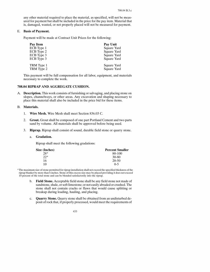
433
708.04 B.3.c
any other material required to place the material, as specified, will not be meas-ured for payment but shall be included in the price for the pay item. Material thatis, damaged, wasted, or not properly placed will not be measured for payment.
E. Basis of Payment.
Payment will be made at Contract Unit Prices for the following:
Pay Item Pay UnitECB Type 1 Square YardECB Type 2 Square YardECB Type 3 Square YardECB Type 3 Square Yard
TRM Type 1 Square YardTRM Type 2 Square Yard
This payment will be full compensation for all labor, equipment, and materialsnecessary to complete the work.
708.04 RIPRAP AND AGGREGATE CUSHION.
A. Description.This work consists of furnishing or salvaging, and placing stone onslopes, channelways, or other areas. Any excavation and shaping necessary toplace this material shall also be included in the price bid for these items.
B. Materials.
1. Wire Mesh.Wire Mesh shall meet Section 836.03 C.
2. Grout.Grout shall be composed of one part Portland Cement and two partssand by volume. All materials shall be approved before being used.
3. Riprap. Riprap shall consist of sound, durable field stone or quarry stone.
a. Gradation.
Riprap shall meet the following gradations:
Size (Inches) Percent Smaller28* 80-10022* 30-8016 20-5010 0-5
*Themaximum size of stone permitted for riprap installation shall not exceed the specified thickness of theriprap blanket by more than 6 inches. Stone of this excess size may be placed providing it does not exceed10 percent of the total stone and can be blended satisfactorily into the riprap.
b. Field Stone.Acceptable field stone shall be any field stone not made ofsandstone, shale, or soft limestone; or not easily abradedor crushed.Thestone shall not contain cracks or flaws that would cause splitting orbreakup during loading, hauling, and placing.
c. Quarry Stone.Quarry stone shall be obtained from an undisturbed de-posit of rock that, if properly processed,wouldmeet the requirements of

434
708.04 B.3.c
concrete coarse aggregate for soundness and abrasion. Local deposits ofsandstones or limestones and similar stone of sedimentary origin shallnot be used as riprap stone.
4. Aggregate Cushion.AggregateCushionshallmeet the requirementsofSec-tion 816 for Class 8.
C. Construction Requirements.
1. General.Theslopeshall beexcavated, shaped, andcompleted to the requiredcross section and elevation.
The laying of stone on sloped areas shall begin at the toe of the slope, and atrench shall be dug to the dimensions specified. When no dimensions areshown, a trench at least one foot deep shall be dug, and the largest stones shallbe placed in the trench. The riprap shall be thoroughly compacted as the con-struction progresses and the finished surface of the riprap shall present aneven, tight surface. Gaps shall be filled with smaller stones.
2. Aggregate Cushion. Aggregate cushion shall be spread over the specifiedarea before placing the riprap.
3. Wire Mesh Riprap. When wire mesh riprap is specified, the riprap stoneshall have wire mesh above and below the layer of rock and around the endsand sides.
Strips of wire mesh shall be laid parallel to the length or direction of theriprap. Adjoining strips and ends of strips shall be tied every 18 inches withwire at all abutting wire sections.
End splices of a strip of wire mesh shall be staggered at least 10 feet with theend splices in the adjacent strip of wire mesh. No length of wire mesh lessthan 10 feet long shall be used.
The lower layer ofwiremeshshall be tied to theupper layer ofmeshwithwireties spaced not over 2 feet center to center each way.
4. Loose Rock Riprap.When loose rock riprap is specified, the rock may beplaced bymechanical means or by hand. Damage to the prepared slope or tostructural components shall be repaired at the Contractor’s expense.
Riprap stone shall be distributed evenly over the riprap area without pocketsof segregated sizes of stone. The stonemay have to be rearranged bymanualor mechanical means if placement methods result in pockets of segregatedsize of stone.
The finished surface of the riprap area shall present an even distribution ofstone sizes over the entire riprap area with no one area of any size deviatingfrom the Plan slope and grade by 6 inches.
D. Method of Measurement.
1. Wire Mesh Riprap.WireMeshRiprapwill bemeasuredby theSquareYardin place. The areawill be computed on the basis of actual surface dimensionsas staked and the specified thickness.

435
708.05 B
2. Loose Rock Riprap.LooseRockRiprapwill bemeasured in thehaulingve-hicle by either the Cubic Yard or by the Ton.
Loose Rock Riprap not placed as specified and not accepted by the Engineerwill be deducted from the total material measured and will not be paid for.
TheEngineerwill deduct for anypartial loaddeliveredor any loadcontainingcontaminants. The deduction will be solely based upon the judgment of theEngineer.
Stone exceeding themaximumallowable size bymore than 10percent in anydimension will be rejected and not measured for payment. The Contractorshall dispose of such oversize stone.
Aggregate Cushion will be measured by the Ton or Cubic Yard as shown onthe Plans. The volumewill be computed on the basis of actual surface dimen-sions as staked and the specified thickness.
E. Basis of Payment.
Payment will be made at Contract Unit Prices for the following:
Pay Item Pay UnitWire Mesh Riprap Square YardLoose Rock Riprap Ton or Cubic YardAggregate Cushion Ton or Cubic Yard
This paymentwill be full compensation for all labor, equipment,materials, exca-vation, and shaping necessary to complete the work.
708.05 FABRIC FORMED SLOPE PROTECTION.
A. Description.Thisworkshall consistof furnishingandplacinganapprovedgrout-injected fabric-formed slope protection.
B. Materials.
Material shall meet the following:
Item SectionCement 804.01Concrete Admixtures 808Water 812Aggregate 816Fly Ash 820Fabric 856.06
Aggregategradingshall be consistent andshall bewell graded fromthemaximumsize which can be conveniently handled with available pumping equipment.
Grout shall consist of a mixture of Portland Cement, fine aggregate, and waterproportioned to provide a pumpable slurry. The mix shall obtain a compressivestrength of 2,500 psi at 28 days. The air content of the mixed grout shall be in therange of 5 to 8 percent.

436
708.05 C
C. Construction Requirements. Only approved mixing and pumping equipmentshall be used inpreparation andhandling of grout.Oil or other rust inhibitors shallbe removed from mixing drums, stirring mechanisms, and other portions ofequipment in contact with grout before the mixers are used. Pumping equipmentshall have a variable flow rate to provide enough pressure for pumping withoutbreaking the fabric.
All material shall be accuratelymeasured by volume or weight as it is fed into themixer.Thequantityofwater shall produceagrouthavingapumpableconsistency.Mixing timeshall be at least oneminute. If agitatedcontinuously, thegroutmaybeheld in the mixer or agitator for 2-1/2 hours or less in temperatures below 70°F,and for two hours or less at higher temperatures. If a lapse in pumping operationoccurs, the grout shall be recirculated through the pump, or themixer drum, or theagitator and pump.
Before grout injection, the fabric must be positioned at its design location. Eachpanel shall be continuous or monolithic for its full width, and all seams must bevertical. Grout shall be introduced into the space between the layers of fabric andshall be injected to avoid excessive pressure on the fabric envelope.Adjacent fab-ric panels shall be joined before grout injection by field sewingwith nylon thread.Where adjacent panels cannot be joined in this manner, or where specified, adja-cent panels shall be lapped aminimum of 2 feet. In no case will simple butt jointsbe permitted.
In the event that blisters or blowouts occur during grout injection, the section af-fected shall be repaired or replaced to match adjacent surfaces.
Sequence of injected grout must follow the manufacturer’s recommendations.
The fabric-forming material shall not be placed or filled on frozen ground. Theinjected grout shall be protected from freezing for at least four days after place-ment. No curing of the completed mat will be required.
D. Method of Measurement. Fabric-Formed Slope Protection, including embed-dedportions,will bemeasured inSquareYard, complete and inplace, basedon thedimensions shown on the Plans.
E. Basis of Payment.
Payment will be made at the Contract Unit Price for the following:
Pay Item Pay UnitFabric-Formed Slope Protection Square Yard
This payment will be full compensation for all labor, equipment, and materialsnecessary to complete the work.
708.06 CONCRETE SLOPE PROTECTION.
A. Description.Thiswork consists of placing a cast-in-place concrete slope protec-tion.
B. Materials.

437
708.06 C.5
Materials shall meet the following:
Item SectionCement 804.01Air-Entraining Admixture 808Curing Materials 810Water 812Aggregate 816Fly Ash 820Preformed Expansion Joint Filler 826.02Joint Sealer 826.02 A.4Reinforcing Steel 836Welded Steel Wire Fabric 836.03 C
C. Construction Requirements.
1. Preparation of Subgrade.The subgrade, for placing concrete slope protec-tion, shall be free of rubbish and vegetation. All loose material shall be thor-oughly compacted. The Contractor shall excavate or backfill as required toobtain the Plan cross section or lines and grades established in the field.
All dry surfaces shall bewetted before placement of concrete. Concrete shallnot be placed on any surface which is spongy or where free water exists.
The areas adjacent to the slope protection shall be left in a smooth, uniformcondition.
2. Placing Reinforcement. The reinforcement shall be free from dirt, detri-mental scale, paint, oil, or other foreign substance.
Welded steelwire fabric andbar reinforcement shall beplacedand secured soits final position in the hardened concrete meets the specified requirements.
3. Composition of Concrete. Concrete shall be Class AE-3 and shall meetSection 802.
4. Placing Concrete.Weather limitations shall be as specified in Section 602.
The concrete shall be placed and consolidatedbymethods that prevent segre-gation or sagging.
Whenever placement of concrete is stopped for the day or otherwise inter-rupted formore than30minutes, a construction joint shall beplacedat theendof a panel.
5. Relief Joints. Joints shall consist of perpendicular grooves in the surface ofthe plastic concrete. The grooves shall meet the dimensions and locationsshown on the Plans. They shall be maintained to the required shape duringany subsequent finishing operations until the concrete has hardened.
The jointsmay be sealed as soon as the concrete becomes stiff enough to pre-vent distortion to the groove or damage to the concrete. The grooves shall becleaned and devoid of foreign substance or freewaterwhen the joint sealer is

438
708.06 C.5
applied. The sealer shall be applied with a caulking gun or other approveddevice.
6. Finishing Concrete. The final finish shall be obtained with a wood float.The surface shall be checked for irregularities with a 10-foot straightedge.The allowable tolerance for depressions or high spots in any 10 feet shall be3/4 inch.
7. Curing Concrete.After final finishing, the concrete shall be cured accord-ing to Section 550.04, except that the minimum curing period shall be fivedays.
8. Tests on Concrete. The concrete will be tested according to Section 802.
D. Method of Measurement. Concrete Slope Protection will be measured parallelto the surface by the SquareYard, complete and in place, based on the dimensionsshown on the Plans.
The cost of all earthwork shall be include in the bid item “Slope Protection.”
E. Basis of Payment.
Payment will be made at the Contract Unit Price for the following:
Pay Item Pay UnitConcrete Slope Protection Square Yard
This payment will be full compensation for all labor, equipment, and materialsnecessary to complete the work.
708.07 SILT FENCE.
A. Description. This work shall consist of furnishing, installing, maintaining, andremoving a geotextile barrier-fence designed to remove suspended particles fromstorm water runoff. The quantities of silt fence shown on the plans may be in-creasedor decreasedasdirectedby theEngineer basedonweather,Contractor op-erations or actual site conditions that occur during construction of the project.Such variations in quantity will not be considered as a change in character ofwork. A Pre-Fabricated silt fence will not be allowed.
B. Materials.
1. Posts. Either wood or steel posts may be used. Wood posts shall be treated(Penta or Green Treated) and shall be a minimum of 6 feet long with mini-mum dimensions of 2 inches diameter for round posts or 1-1/2 inches by1-1/2 inches for rectangular posts. Steel posts shall be a minimum of 5 feetlong,weigh aminimumof 1.3 pounds/foot and have projections to aid in fas-tening the wire or fabric. Steel posts shall have a metal plate welded near thebottom such that when the post is driven to the proper depth, the plate will bebelow the ground level for added stability.
2. Woven Wire.When backing for a filter fabric silt fence is required, a steelwire fence fabric shall be used. Awoven wire fence shall conform to ASTM

439
708.07 C.1
A116,Class 1 zinc coating forwire. Thewovenwire support fence shall be atleast 32 incheshigh and amaximumopening size of 6 inchesby6 inches.Thewire shall be a minimum of 14 gage grade 60.
3. Filter Fabric. Silt fence fabric shall conform to AASHTOM 288 silt fenceSpecification. Filter fabric shall be composed of fibers consisting of longchain synthetic polymers composed of at least 95 percent by weight of poly-olefins, polyesters or polyomides. The fibers shall be formed into a networksuch that the filaments or yarns retain dimensional stability relative to eachother. The filter fabric shall be free of any treatment or coating which mightadversely alter its physical properties after installation. The fabric shall befree of defects or flaws that significantly affect its physical and/or filteringproperties. The fabric shall have a minimum width of 36 inches. The filterfabric shall be furnished with suitable wrapping for protection against mois-ture and extended ultraviolet exposure prior to placement.
The filter fabric shall meet theminimum physical requirements contained inTable 1. Unless otherwise indicated, numerical values represent the mini-mum average roll value. The required numerical value for the AOS is themaximumallowable inSIUnits and theminimumallowable inU.S.StandardSieve Numbers.
Table 1Property Test Method Supported * Unsupported
Grab Tensile Strength (lbs) ASTM D 4632
Machine 90 123
Cross Machine 90 101
Permittivity (sec--1) ASTM D 4491 0.05 0.05
Water Flow Rate(gpm / ft2)
ASTM D 4491 4.43 4.43
AOS (US Sieve #) mmSieve #
ASTM D 4751 0.600#30
0.600#30
UV Resistance (%) ASTM D 4355 70%@500 hrs 70%@500 hrs
*Silt fence support shall consist of 14 gage steelwirewith ameshmaximum spacing of 6 inches by 6 inches.
C. Construction Requirements.
In addition to the StandardDrawing shown in the Plans, the followingwill apply:
1. Installation. The geotextile at the bottomof the fence shall be buried in a “J”configuration to a minimum depth of 6 inches in a trench so that no flow canpass under the silt fence. Wire support fence if used shall also be buried aminimum of 2 inches. The trench on the upstream side of the silt fence shallbe backfilled and the soil compacted over the geotextile.
Silt fence fabrics shall be spliced together only at support posts with a mini-mum of 18 inches of overlap and in suchmanner to prevent silt from passingbetween the two ends. At the time of installation, the fabric or fence will berejected if it has any defects, deterioration, or other damage incurred duringmanufacture, transportation, storage, or installation.
Posts shall be spaced4 feet apart anddrivenorplacedaminimumof20 inchesinto the ground. Depth shall be increased to 24 inches if fence is placed on a

440
708.07 C.1
slope 3:1 or greater. Geotextiles shall be attached to posts by staples, wire,nails, or in accordance with the manufacturer’s recommendations. Wire sta-ples shall be a No. 17 gauge minimum and shall have a minimum 0.75 in.wide crownand0.5 in. long legs. Staples shall be evenly placedwith at least 4per post. Nails shall be aminimumof 14 gauge, 1 inch long, with 0.75 buttonheads. Nails shall be evenly spaced with at least four per post.
Silt fences should be continuous and transverse to the flow. The silt fenceshould follow the contours of the site as closely as possible. The fence shallalso be placed such that the water cannot flow around the end of the fence.
2. Maintenance.Sediment deposits shall be removedwhen the deposit reacheshalf of the height of the silt fence at the lowest area or when directed by theEngineer. Silt fence shall be inspected by the Contractor immediately aftereach rainfall and at least daily during prolonged rainfall. Any deficienciesshall be immediately corrected. Filter fabric shall be removed and replacedwhenever it has deteriorated to such extent that it reduces the effectiveness ofthe silt fence. In addition, the Contractor shall make daily review of the loca-tion of silt fences in areaswhere construction activities have changed the nat-ural contour and drainage runoff to ensure that the silt fences are properly lo-cated for effectiveness. Where deficiencies exist, additional silt fences maybe installed as directed by the Engineer.
If a silt fence, or portion of a fence, is located in an area where removing thesediment is not possible, then a second silt fence may be installed at the dis-cretion of the Engineer. In this case, the silt fences or portions involved, willbe measured and paid for at the unit price for silt fence.
Silt fence shall remain in place until the vegetative coverage is restored toseventy percent of preexisting vegetation. Fence materials that are removedwill be disposed of by the Contractor. Upon removal, the Contractor shalldress the area to give a pleasing appearance, and vegetate all bare areas in ac-cordance with the contract requirements. If the new reshaped area still posesan erosion threat, the Engineer may require the Contractor to erect a new siltfence. If vegetative coverage isnot restored to70percentof preexistingvege-tation prior to project acceptance, the silt fence will remain in place and willbe removed by the Department.
D. MethodofMeasurement.Silt fencewill bemeasured to the nearest linear foot offence actually installed in accordance with the Plans or as required by the Engi-neer. Themeasurement for payment excludes the fabric or fencematerial used foroverlapping as well as fabric used for seam overlaps.
E. Basis of Payment.
Payment will be made at the Contract Unit Price for the following:
Pay Item Pay UnitSilt Fence Supported Linear Foot InstalledSilt Fence Unsupported Linear Foot Installed
This payment will be full compensation for all materials, equipment and labor toinstall and remove the silt fence.

441
708.08 C.2
Cleaning of the sediment deposits shall be paid at the price listed in the “PriceSchedule PS--1.”
708.08 FIBER ROLLS.
A. Description.Thiswork shall consist of furnishing, installing,maintaining and re-moving fiber rolls for erosion control.
B. Materials.Fiber rolls shall consist of hayor straw free of noxiousweeds, orwoodexcelsior that has been compressed and stuffed into degradable netting. Dimen-sions of the 6-inch roll shall be approximately 6 inches nominal in diameter, di-mensions of the 12-inch roll shall be approximately 12 inches nominal in dia-meter, and dimensions of the 20-inch roll shall be approximately 20 inchesnominal in diameter.
C. Construction Requirements. In addition to the Standard Drawing shown in thePlans, the following will apply:
1. Installation. Each fiber roll shall be overlapped 1 foot minimum and tiedtightly together, to prevent flow between the fiber roll ends. Fiber rolls shallbe trenched and staked according to manufacturer’s specifications. Trench-ing is not required for “Fiber Rolls 20 inch.” Use 6-inch rolls around dropinlets and on contours for sheet flow down backslopes and foreslopes. Use12-inch and 20-inch rolls in the ditch bottom, pipe inlets, and at the edge ofthe right of way.
2. Maintenance.Sediment deposits shall be removedwhen the deposit reacheshalf the height of the fiber roll or when directed by the Engineer. Fiber rollsshall be inspected by the Contractor immediately after each rainfall and atleast dailyduringaprolonged rainfall.Anydeficiencies shall be immediatelycorrected. Fiber rolls shall be removed and replacedwhenever the fiber rollsdeteriorate to such extent that the effectiveness of the fiber roll is reduced.The Contractor shall make daily review of the location of fiber rolls in areaswhere construction activities have changed the natural contour and drainagerunoff to ensure that the fiber rolls are properly located for effectiveness.Wheredeficiencies exist, additional fiber rollsmaybe installedasdirectedbythe Engineer.
If a fiber roll, or portion of a fiber roll, is located in an area where removingthe sediment is not possible, then a second fiber roll may be installed at thediscretion of the Engineer.
Fiber rolls shall remain in place until the vegetative coverage is restored to 70percent of the preexisting vegetation. Fiber roll materials that are removedwill be disposed of by the Contractor. Upon removal, the Contractor shalldress the area to give a pleasing appearance, and vegetate all bare areas in ac-cordance with the contract requirements. If the new reshaped area still posesan erosion threat, the Engineer may require the Contractor to install fiberrolls. If vegetative coverage is not restored to 70 percent of preexistingvegetation prior to project acceptance, the fiber roll will remain in place andwill be removed by the Department.

442
708.08 D
D. Method ofMeasurement. Fiber rolls will bemeasured to the nearest linear foot,excluding overlaps, installed in accordance with the Plans or as required by theEngineer.
E. Basis of Payment. Payment will be made at the Contract Unit Price for the fol-lowing:
Pay Item Pay UnitFiber Rolls __ IN Linear Foot Installed
This payment will be full compensation for all materials, equipment and labor tofurnish, install, maintain and remove the fiber rolls.
Cleaning of the sediment deposits shall be paid at the price listed in the “PriceSchedule PS-1.”
708.09 FLOTATION SILT CURTAIN
A. Description. This work consists of furnishing, installing, maintaining, and re-moving flotation silt curtain as a temporary erosion control measure.
B. Materials. Floating Silt Curtain should meet the following materials properties:
Materials andProperties Still Water
Moving Water orWork Area
Curtain Fabric Impermeablevinyl-nylon laminate
Impermeablevinyl-coated nylon
Mass/sq. yd. 18 oz. 22 oz.
Grab Tensile Strength 300 lbs. 500 lbs.
Depth of Curtain 2 -- 10 feet
Flotation 6-inch dia. Marine qualityexpanded polystyrene
8” dia. Marine qualityexpanded polystyrene
Net Buoyancy per foot 13 lbs. 20 lbs.
Top LoadCarrying Components
Fabric only Fabric + 5/16 inchgalvanized steel cable9,800 lb. min break
strength
Ballast (min.) 1/4 inch galvanized chain 5/16 inch galvanized chain
ConnectionsBetween Sections
Laced grommets Aluminum collar rein-forced quick disconnects
C. Construction Requirements.
1. Installation. In all cases anchor lines shall be attached to the flotationdevice,not to the bottom of the silt curtain.
a. StillWater. In still water lakes or ponds both ends of the curtain shall besecured on land using the anchor points and using anchor buoys if bot-tom anchors are employed. The curtain shall be towed out, in the furledcondition, and attached to these stakes or anchor points. Any additionalstakes or anchors required tomaintain the desired location of the curtain
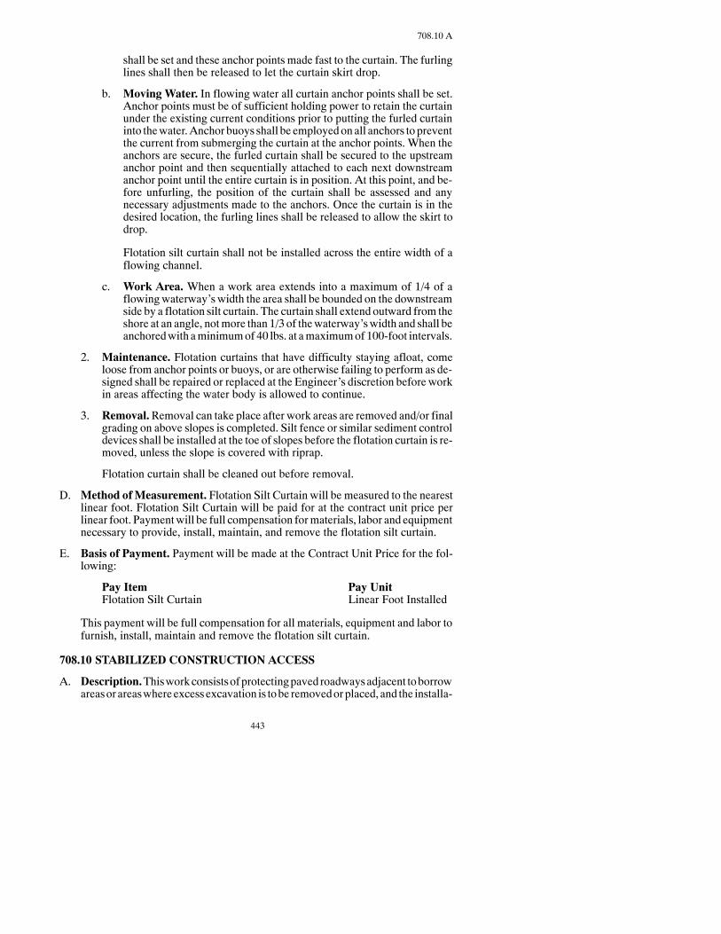
443
708.10 A
shall be set and these anchor points made fast to the curtain. The furlinglines shall then be released to let the curtain skirt drop.
b. Moving Water. In flowing water all curtain anchor points shall be set.Anchor points must be of sufficient holding power to retain the curtainunder the existing current conditions prior to putting the furled curtaininto thewater.Anchor buoys shall be employedonall anchors to preventthe current from submerging the curtain at the anchor points. When theanchors are secure, the furled curtain shall be secured to the upstreamanchor point and then sequentially attached to each next downstreamanchor point until the entire curtain is in position. At this point, and be-fore unfurling, the position of the curtain shall be assessed and anynecessary adjustments made to the anchors. Once the curtain is in thedesired location, the furling lines shall be released to allow the skirt todrop.
Flotation silt curtain shall not be installed across the entire width of aflowing channel.
c. Work Area. When a work area extends into a maximum of 1/4 of aflowingwaterway’swidth the area shall be bounded on the downstreamside by a flotation silt curtain. The curtain shall extend outward from theshore at an angle, notmore than 1/3 of thewaterway’swidth and shall beanchoredwith aminimumof 40 lbs. at amaximumof 100-foot intervals.
2. Maintenance. Flotation curtains that have difficulty staying afloat, comeloose from anchor points or buoys, or are otherwise failing to perform as de-signed shall be repaired or replaced at the Engineer’s discretion before workin areas affecting the water body is allowed to continue.
3. Removal.Removal can take place after work areas are removed and/or finalgrading on above slopes is completed. Silt fence or similar sediment controldevices shall be installed at the toe of slopes before the flotation curtain is re-moved, unless the slope is covered with riprap.
Flotation curtain shall be cleaned out before removal.
D. Method ofMeasurement. Flotation Silt Curtain will be measured to the nearestlinear foot. Flotation Silt Curtain will be paid for at the contract unit price perlinear foot. Paymentwill be full compensation formaterials, labor and equipmentnecessary to provide, install, maintain, and remove the flotation silt curtain.
E. Basis of Payment. Payment will be made at the Contract Unit Price for the fol-lowing:
Pay Item Pay UnitFlotation Silt Curtain Linear Foot Installed
This payment will be full compensation for all materials, equipment and labor tofurnish, install, maintain and remove the flotation silt curtain.
708.10 STABILIZED CONSTRUCTION ACCESS
A. Description.Thisworkconsistsofprotectingpaved roadwaysadjacent toborrowareasor areaswhereexcessexcavation is tobe removedorplaced, and the installa-

444
708.10 A
tion, maintenance and removal of stabilized construction accesses at those loca-tions.
B. Materials.
1. Aggregate. Aggregate material for the Stabilized Construction Access willmeet the following requirements:
Sieve Size Percent Passing3 inch 1001 inch 0
The aggregate shall have 75 percent fractured faces
2. GeotextileFabric.Geotextile fabric shallmeet the requirements forR1Fab-ric according to Section 858.
C. Construction Requirements. If an access is constructed that restricts flowthrough a ditch, the contractorwill determine the correct length and size culvert tomeet the existing conditions. If an access is placedwhere topsoil exists, the topsoilshall be stripped before the access is constructed and replaced and reseeded afterremoval.
A Stabilized Construction Access may not be placed in an area designated as awetland.
D. Maintenance.The Contractor shall maintain all stabilized construction accessesfor the duration of their use. TheContractor shall sweep clean all construction-relateddebris tracked onto the existing paved roadways adjacent to these locations at theend of eachworking day unless otherwise approved by the engineer. The limits ofthe maintenance shall be the entire length of the haul road to and from thedestination.
Additional rock shall be added as needed.
E. MethodofMeasurement.StabilizedConstructionAccesseswill bemeasuredbythe number of individual access points installed as part of the constructioncontract, without regard to size or location. The pay item shall be considered fullpayment for any topsoil or seeding requirements where the access has beenconstructed.
F. Basis of Payment. Payment will be made at the Contract Unit Price for the fol-lowing.
Pay Item Pay UnitStabilized Construction Access Each
Thispaymentwill be full compensation for all equipment, labor andmaterials (in-cluding fabric, aggregate, culvert, etc) to construct, maintain and remove Stabi-lized Construction Accesses.

445
709.03 A
SECTION 709GEOTEXTILE FABRICS
709.01 DESCRIPTION.
This work consists of furnishing and installing a geotextile fabric.
709.02 MATERIALS.
The geotextile fabric specified shall meet the requirements of Section 858.
709.03 CONSTRUCTION REQUIREMENTS.
A. General.
The surface receiving the fabric shall be smooth and free of stones, sticks, andother debris or irregularities that might puncture the fabric. The fabric shall beplaced free of wrinkles and shall be protected at all times during construction.Construction equipment shall not be operated on the fabric.
The fabric shall be overlapped a minimum of 18 inches at all splices or joints. Inlieu of joint overlapping,multiple fabric piecesmaybe sewed if the seamstrengthmeets the seamstrength requirements listed inSection858.01A.A401stitchcon-forming toFederalStandardNo.751a shall beused for all seams.Overlapping“J”seams are required for field seams. All seams shall be sewnwith two parallel stitchlines spaced approximately 1/4 inch apart. The outside stitch shall be placedapproximately 1 inch from the edge of the fabric. The thread shall be of amaterialthat meets the requirements specified for the fabric.
The geotextile fabric and a certification of compliance shall be delivered to theproject at least 21 days prior to its incorporation into thework. Fabric shall be ap-proved by the Engineer before installation.
If a fabric is tested and fails, any retestswill be at the cost of theContractor, unlessthe results of the retest show the fabric passes.
If the Engineer allows installation and the fabric fails to meet the specified re-quirements a minimum price adjustment of 20 percent will be assessed to the bidprice for any fabric installed.Actual penaltieswill be determinedby theEngineer,based on projected performance of fabric. If the failing fabric jeopardizes the in-tegrity of the project, the fabric will be removed and replaced at the Contractor’sexpense.
If sewn seams are going to be used, the Contractor shall also furnish a sewn seamsample, using the same geotextile fabric, thread, seam spacing and number, andoverlap distance as are intended or required for use in the work.
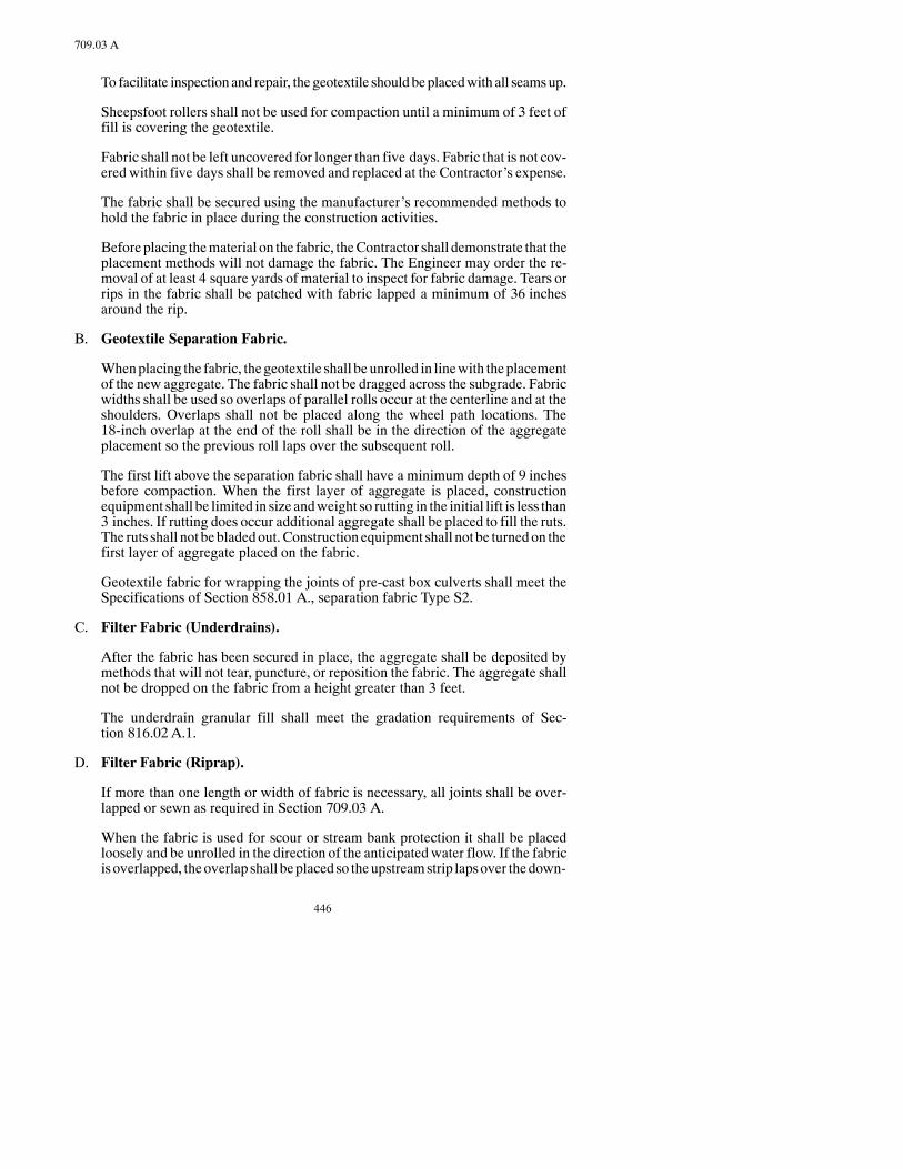
446
709.03 A
To facilitate inspectionand repair, the geotextile shouldbeplacedwith all seamsup.
Sheepsfoot rollers shall not be used for compaction until a minimum of 3 feet offill is covering the geotextile.
Fabric shall not be left uncovered for longer than five days. Fabric that is not cov-ered within five days shall be removed and replaced at the Contractor’s expense.
The fabric shall be secured using the manufacturer’s recommended methods tohold the fabric in place during the construction activities.
Beforeplacing thematerial on the fabric, theContractor shall demonstrate that theplacement methods will not damage the fabric. The Engineer may order the re-moval of at least 4 square yards of material to inspect for fabric damage. Tears orrips in the fabric shall be patched with fabric lapped a minimum of 36 inchesaround the rip.
B. Geotextile Separation Fabric.
Whenplacing the fabric, thegeotextile shall beunrolled in linewith theplacementof the new aggregate. The fabric shall not be dragged across the subgrade. Fabricwidths shall be used so overlaps of parallel rolls occur at the centerline and at theshoulders. Overlaps shall not be placed along the wheel path locations. The18-inch overlap at the end of the roll shall be in the direction of the aggregateplacement so the previous roll laps over the subsequent roll.
The first lift above the separation fabric shall have a minimum depth of 9 inchesbefore compaction. When the first layer of aggregate is placed, constructionequipment shall be limited in size andweight so rutting in the initial lift is less than3 inches. If rutting does occur additional aggregate shall be placed to fill the ruts.The ruts shall not bebladedout.Constructionequipment shall not be turnedon thefirst layer of aggregate placed on the fabric.
Geotextile fabric for wrapping the joints of pre-cast box culverts shall meet theSpecifications of Section 858.01 A., separation fabric Type S2.
C. Filter Fabric (Underdrains).
After the fabric has been secured in place, the aggregate shall be deposited bymethods that will not tear, puncture, or reposition the fabric. The aggregate shallnot be dropped on the fabric from a height greater than 3 feet.
The underdrain granular fill shall meet the gradation requirements of Sec-tion 816.02 A.1.
D. Filter Fabric (Riprap).
If more than one length or width of fabric is necessary, all joints shall be over-lapped or sewn as required in Section 709.03 A.
When the fabric is used for scour or stream bank protection it shall be placedloosely and be unrolled in the direction of the anticipated water flow. If the fabricisoverlapped, theoverlap shall beplacedso theupstreamstrip lapsover thedown-

447
709.04 B
stream strip. The laps along the length of the fabric, parallel to the waters edge,shall be placed so the upper strip overlaps the lower strip. All overlaps shall bepinned or stapled at 3-foot intervals.
Fabric used toprotect againstwave actionmaybeunrolledparallel or perpendicu-lar to thewaters edge. The joints or seamsof all fabric placed parallel to thewatersedge shall be sewn.
The riprap shall be deposited and spread over the fabric by methods that do nottear, puncture, or reposition the fabric. Riprap stones less than 250 pounds shallnot be dropped on the fabric from a height greater than 3 feet. Stones greater than250 pounds shall be placed with no free-fall. Contouring of the stones shall beachieved during their initial placement. The stones shall not be rolled along thesurface. Placement of the stone cover shall begin at the base of the slope and at thecenter of the geotextile covered zone.
E. Geotextile Reinforcement Fabric.
Reinforcement fabric that is placedunder roadwayshall beunrolledparallel to thecenterline of the road and shall be placed as shown in thePlans. The fabric shall beplaced such that it is taut and pinned, using a minimum of 6-inch pins. The pinsshall be placed at a nominal 15-foot spacing along all edges and at all corners,prior to placing any material on the fabric.
The fabric shall be overlapped aminimumof 30 inches at all splices or joints. The30-inch overlap at the end of the roll shall be in the direction of the aggregateplacement so the previous roll laps over the subsequent roll.
The first lift above the reinforcement fabric shall have aminimum lift of 12 inchesbefore compaction.
Small dozer equipment or front-end loaders with low ground pressures shall beused to spread the cover material.
F. Shipping and Storage.
Geotextile labelling and identification shall comply to ASTMD4873-95. If a la-bel is removed during sampling or other reasons, the roll must be relabeled.
Packaging, handling, and storage of geosynthetics shall conform to ASTM D4873-95 and the following requirements. Each Geotextile roll shall be wrappedwith awaterproof cover ormembrane for protection during shipping and storage.Geotextiles shall notbeexposed toultraviolet light formore than14daysandshallbe elevated off the ground during storage.
709.04 METHOD OF MEASUREMENT.
A. Geotextile Separation Fabric.Thefabricused for separationandfor riprapshallbemeasured by the actual surface area covered to the nearest Square Yard. No al-lowance will be made for overlaps, drainage trenches, or cutoff trenches unlessotherwise shown on the Plans.
B. Filter Fabric (Underdrains). The fabric used for underdrains will be measuredby the SquareYard, complete and in place, based on the dimensions shown on thePlans.
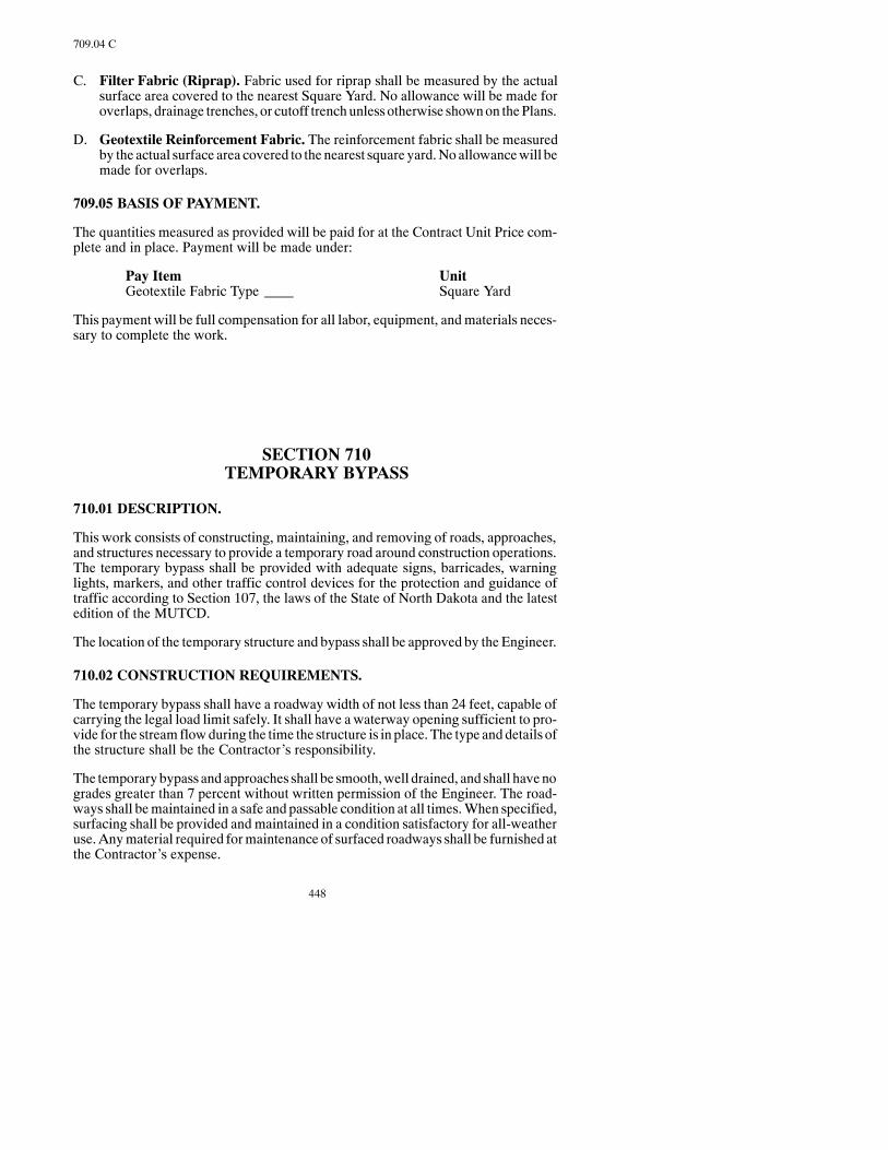
448
709.04 C
C. Filter Fabric (Riprap). Fabric used for riprap shall be measured by the actualsurface area covered to the nearest Square Yard. No allowance will be made foroverlaps, drainage trenches, or cutoff trenchunlessotherwise shownon thePlans.
D. Geotextile Reinforcement Fabric. The reinforcement fabric shall be measuredby the actual surface area covered to the nearest square yard.Noallowancewill bemade for overlaps.
709.05 BASIS OF PAYMENT.
The quantities measured as provided will be paid for at the Contract Unit Price com-plete and in place. Payment will be made under:
Pay Item UnitGeotextile Fabric Type Square Yard
This payment will be full compensation for all labor, equipment, andmaterials neces-sary to complete the work.
SECTION 710TEMPORARY BYPASS
710.01 DESCRIPTION.
This work consists of constructing, maintaining, and removing of roads, approaches,and structures necessary to provide a temporary road around construction operations.The temporary bypass shall be provided with adequate signs, barricades, warninglights, markers, and other traffic control devices for the protection and guidance oftraffic according to Section 107, the laws of the State of North Dakota and the latestedition of the MUTCD.
The location of the temporary structure and bypass shall be approved by the Engineer.
710.02 CONSTRUCTION REQUIREMENTS.
The temporary bypass shall have a roadway width of not less than 24 feet, capable ofcarrying the legal load limit safely. It shall have a waterway opening sufficient to pro-vide for the streamflowduring the time the structure is in place. The type anddetails ofthe structure shall be the Contractor’s responsibility.
The temporarybypass andapproaches shall be smooth,well drained, and shall havenogrades greater than 7 percent without written permission of the Engineer. The road-ways shall bemaintained in a safe and passable condition at all times.When specified,surfacing shall be provided andmaintained in a condition satisfactory for all-weatheruse.Anymaterial required formaintenance of surfaced roadways shall be furnished atthe Contractor’s expense.
449
714.02 A
TheContractor shall assume anyand all liability for damage resulting from theneglector failure to safeguard highway traffic or property.
The temporary bypass shall not be removed until the new structure is opened to trafficand removal is authorizedby theEngineer.Removal shall include a full clean-upof thesite, complete removal of all structures, etc.; and restoration of the area to its originalcondition to the satisfaction of the Engineer.
TheContractor shallmaintain traffic on the bypass or bypasses; and furnish assistanceto traffic, if required.
710.03 METHOD OF MEASUREMENT.
Each temporary bypass shall be designated by its station number; and for the purposeof measurement and payment, it shall be considered as a complete and separate unit.
710.04 BASIS OF PAYMENT.
The basis of payment shall be the Contract Unit Price bid for “Temporary Bypass.”
This payment will be full compensation for all labor, materials, and equipment neces-sary to complete the work.
The furnishing of, maintenance of, and payment for all signs, barricades, warninglights, and other traffic control devices shall be according to Section 704.
Where there isnoContractUnitPrice for “TemporaryBypass,”each temporarybypassordered by the Engineer shall be paid for under Section 104.03.
SECTION 714CULVERTS, STORM DRAINS, EDGE DRAINS,
AND UNDERDRAINS
714.01 DESCRIPTION.
This work consists of installing culverts, storm drains, edge drains, and underdrainsdesigned to intercept and carry off surface or underground water.
Culverts, stormdrains, edgedrains, andunderdrainsof thevarious types and sizes spe-cified will, at times, be referred to as pipe or conduit in these Specifications.
714.02 MATERIALS.
A. Culverts and Storm Drains.
450
714.02 A
Materials shall meet the following:
Item SectionConcrete Culvert and Storm Drain Pipe 830.01 AReinforced Concrete Culvert and Storm Drain Pipe 830.01 BMetallic (Zinc or Aluminum) Coated CorrugatedSteel Culverts, Underdrains, and Storm Drains 830.02 B
Corrugated Aluminum Alloy Culverts 830.02 CSmooth Wall Steel Pipe Culverts 830.02 DPolymer Coated Corrugated Steel Pipe 830.02 GCorrugated Polyethylene Culverts 830.03 F
Mortar shall consist of a mixture of one part Portland Cement to two parts mortarsand, and sufficient water to furnish proper consistency.
All materials must be approved by the Department before incorporation into thework.
When shown as conduit in the Contract, the Bidder may choose permissible op-tions in types of pipe for culverts. The Bidder shall be aware of the minimumcover requirements of the conduit options. The options will be shown in the Pro-posal.
At locations where new end sections are to be placed on existing pipe, the Con-tractor is required to identify whether the type of end section needed is male orfemale.
B. Underdrains.
Materials shall meet the following:
Item SectionUnderdrain Granular Fill Material(Screen Analysis only) 816.02 A.1
Perforated, Corrugated Polyethylene,or Plastic Pipe 830.03 A.4
C. Bridge Approach Drains.
Materials shall meet the following:
Item SectionConcrete Class AE 802Precast Reinforced Concrete Pipe for Catch Basin 830.01 BCorrugated Metal Pipe 830.02 BPlastic or PVC Pipe 830.03Grates, Frames, and Boxes 834.02 B,
834.02 C, or834.02 D
D. Edge Drains.
Materials shall meet the following:

451
714.03 A.2
Item SectionTrench BackfillConcrete Sand* 816.01Size 4 or 5 Concrete Aggregate* 816.02Permeable Trench Backfill Cl.2 816.03Permeable Base Aggr. Cl.7 816.03Class 43 Chips* 816.03
Perforated, Corrugated, P.E. Pipe 830.03 A.4PVC Discharge Pipe 830.03 A.3Geotextile Fabric 858
*Sieve analysis only.
714.03 CONSTRUCTION REQUIREMENTS.
If the existing drainage facilities become inoperable before the newdrainage system isfunctioning, the Contractor shall provide sufficient temporary pumping and/or drain-age facilities to keep the roadway drained to the satisfaction of the Engineer. The costof providing sufficient temporarypumpinganddrainage shall not bebid separatelybutshall be included in the price bid for other items.
A. Culverts and Storm Drains.
1. Excavation. Trenches shall be excavated to allow for proper jointing of thepipe, and thorough compaction of the bedding and backfill material underand around the pipe.
The completed trench bottom shall be firm for its full length and width.Where required, the trench shall have a longitudinal camber of themagnitudespecified.
The foundation for each type of bedding shall be adequate to furnish a uniformstable support. Where unstable material is encountered, it shall be removed tothe depth directed by the Engineer and replaced with granular backfill. Rock,shale, or hard pan shall be removed to a depth 1 foot below the bedding eleva-tion and replaced with granular backfill.
Excavation required inexcessof1 footbelowthe specifiedbeddingelevationwill be paid for as Common Excavation.
Disposal of excess excavation from pipe trenches shall be off the Right ofWay, at a location approved by the Engineer.
2. Bedding.When bedding is required, it shall meet the details shown on thePlans or Standard Drawings.
Bedding for mainline pipe shall consist of the type of aggregate specified inthe Plans. The beddingmaterial shall be at least 2 feet thick beneath the pipe.
Bedding for approach pipe shall consist of bedding the pipe to a depth of notless than 10 percent of its total height. The bed shall be shaped to fit the con-duit and shall have recesses shaped to receive the bell. Tamping shall be asspecified above for mainline pipe.
452
714.03 A.3
3. Handling and Assembly. Any damage to the Polymer Coated CorrugatedSteelPipeduring the shipment, handling, or installationof theculvert shall berepaired according to AASHTOM 243 or, if necessary, replaced. Any suchrepairs or replacements shall be done at the Contractor’s expense and to thesatisfaction of the Engineer prior to the acceptance of the purchase.
4. Laying Pipe. Laying of pipe shall begin at the downstream end. The lowersegment of the pipe shall be in contactwith the shapedbedding throughout itsfull length. Bell or groove ends of rigid pipe and outside circumferential lapsof flexible pipe shall be placed facing upstream. PolymerCoatedCorrugatedSteel Pipe shall be handled at all times with equipment such as wide canvasslings andwidepadded skids designed to prevent damage to the pipe coating.
5. Joining Pipe.Rigid pipemaybe of “bell and spigot” or “tongue andgroove”design unless one type is specified. Pipe sections shall be joined so the endsare fully entered and the inner surfaces are flush and even.
When jointing or tying of pipe sections is required, the jointing material andconstruction methods will be as shown on the Plans or Standard Drawings.
Flexible pipe shall be firmly joined by coupling bands.
6. Relaid Pipe. The Engineer will determine which sections of salvaged pipeare suitable for relaying.
All salvaged pipe shall be cleaned of foreign material before reinstallation.
Any connecting devices or seals needed to join pipe or end sections shall befurnished by the Contractor. The cost of these items shall be included in theprice bid for “Relaying Pipe” or “Relaying End Sections.”
7. Backfilling for Pipe Installed in Embankments. After installing the pipeon the required bedding, suitable backfill shall be placed along each side ofthe pipe in layers not exceeding 12 inches. Each layer shall be compacted tothe required density. If a specified density is not required, compaction shallbe according to Section 203.02 I.
All suitable excavated material may be used for backfilling, and the balanceshall be placed in the roadway embankments. Soft, spongy, or other unsuit-able material shall be placed on the slopes of the roadway embankment orwasted at locations acceptable to the Engineer.
Material around the sides andunder the haunches of the conduit shall be thor-oughly compacted.
8. Backfilling for Pipe Installed in Trenches. After the pipe is installed, thetrench shall be backfilled with suitable material according to Section 210.
9. Corrugated Polyethylene Pipe. A minimum of 30 days after the pipe isinstalled, the Contractor (under the observation of the Engineer) shall pass anine pointmandrel or other approved object through the pipe to check for de-formation. The mandrel diameter shall not be less than 95 percent of the in-side diameter of the pipe. If the plastic pipe has deformed more than 5 per-

453
714.03 C
cent, it shall be replaced at theContractor’s expense.Another 30-daywaitingperiod will commence upon installation of the replacement pipe.
10. Connection toManholes, Inlets, andPipes. If the proposed pipe or drain isto be connected to a manhole, inlet barrel, or pipe, the cost of materials,equipment and labor to cut the manhole, inlet barrel, or pipe entrance and togrout the connections shall be included in other items.
B. Smooth Wall Steel Pipe Culvert. Smooth wall steel pipe culverts shall be in-stalledusingequipment that encases thehole as theearth is removed.Boringwith-out the concurrent installation of the steel pipe will not be permitted. All joints insteel pipe shall beweldedaccording toAWSD1.1. Steel pipe shall extend throughthe undisturbed fill and shall be installed without disrupting traffic or damagingthe roadway grade and surface. Use of water in the process of boring or jacking isprohibited.
The borings shall bemade in straight lines and to the grade and alignment shown.The flow line elevation at the starting point for jacking shall be within 0.1 foot ofthe staked grade; the flow line shall not be reversed at any point; and the line andgrade at anypointwithin thepipe shall not varybymore than0.5 foot from the lineand grade designated.
Only welders qualified for groove welded pipe position 5G shall be employed tosplice smooth wall steel pipe culverts. Welders shall be qualified according toAWSD1.1 except full penetration shall not be required. The root pass and the re-maining part of the weld, including the reinforcement, shall meet the require-ments of AWSD1.1. Reinforcement shall not exceed 1/8 inch in height. The De-partmentwill accept thewelding test results administered by an independent test-ing agency. The cost of welder testing and certification shall be the responsibilityof the Contractor. A copy of thewelder’s qualification test certificate shall be fur-nished to theEngineer before thewelder performs anywelding. TheEngineer hasthe right to require a requalification test at any time.
C. Underdrains. Underdrains shall be constructed to the line, grade, and locationsshown.
The perforated underdrain shall be encased in a granular fill trench section withthe trench section enclosed with filter fabric. The filter fabric shall meet the re-quirements of Section 709.02, Filter Fabric Underdrain. The trench section shallbe 1.5 feet wide and 2.0 feet deep. The underdrain shall rest on the filter fabric atthe bottomof the trench, at the desiredgrade, prior to backfillingwith the granularfill. No more than 1 inch of granular material may be used to adjust the pipe tograde. The filter fabric shall overlap approximately 12 inches.
Underdrain size and perforation layout shall be as shown in the Contract.
ThePVCjoints shall be solvent cementedusing themanufacturer’s recommenda-tions.
Where a drain connects with amanhole, catch basin, or pipe, the connection shallbe made at the Contractor’s expense.
Backfill above the granular fill material shall be ordinary backfill as specified inSection 210.

454
714.03 D
D. Bridge Approach Drains. Construction of bridge approach drains shall be asshown in the Contract.
Excavation shall be according to the details shown. The backfill shall be placedwithout disturbing the units, and shall be compacted to the same density as the ad-jacent embankment.
E. Edge Drains. Edge Drains shall be constructed along the pavement edge asshown on the Plans. The drains shall be outletted at approximate intervals of 250feet and at low points in the flow line of the edge drain.
The drains shall be placed by a machine trencher capable of cutting the trench,lining the trench with a geotextile fabric, and laying the pipe in a continuous op-eration. The drains shall be placed at aminimumgrade of 0.2 percent. Laser gradecontrolwill be requiredon the trenchingmachinewhenever thepipegradesdonotfollow the pavement grades at a constant depth. The trenching equipment shall bedesigned andoperated so the excavatedmaterial does not fall back into the trench.The excavated trench material shall be disposed of by the Contractor.
The trench backfill shall be compactedwith a vibratory shoe compactor narrowerthan the trench, but not more than 2 inches less than the trench width. The trenchbackfill shall be compacted adequately to ensure that additional settlement willnot occur.
When edge drains are installed adjacent to a permeable base material, the trenchshall bewrappedwithaTypeD2geotextile drain fabric.The fabric shall bepinneddirectly below the flow line of the permeable basematerial so the flowofwater tothedrain isnot impeded.Concrete sandwill notbeused for trenchbackfill onproj-ects using a permeable base material.
When edge drains are installed on a project with a non-permeable base material,the PEpipe shall be enclosed in a geotextile fabric sock. TheContractormay electto use a Type D3 or Type D4 geotextile drain fabric for the sock.
Edge drains that outlet to the ditch shall be constructed concurrentlywith the lon-gitudinal edge drains and laid at right angles to the roadway centerline. The dis-chargepipe shall be aPVCpipe laid at aminimumgradeof 2percent. The connec-tion to the edge drain pipe shall be made with a non-perforated PE pipe placedwith a 3-foot radius. Twodrains coming together at a lowpoint shall be connectedto separate discharge pipes. The discharge trenches shall be constructed similar tothe drains, but shall be backfilled with the existing soil. Headwalls shall beinstalled aminimumof6 inches above theditchgrade.Thedischargepipe shall beinserted and coupled to the headwallwith grout. Theuppermost point of the head-wall shall be placed flushwith the roadway inslope. The inslope shall be shaped toconform to the sides and toe of the headwall. Theheadwall and rodent screen shallbe installed at the same time the outlet pipe is installed.
Each headwall shall be provided with a rodent screen that fits snuggly into theheadwall so mice and other rodents are unable to enter the drain. The rodentscreens must be removable, the Contractor will not be permitted to grout thescreens into place.
Edge drains that outlet to a storm sewer system shall be coupled to the inlet by useofgrout, rubberor plasticgaskets, or byagasket joint inserted into a thermoplastic
455
714.04 E
coupling cast into the inlet,manholes, or pipe. The connections to the stormsewershall be made concurrently with the installation of the drain. The cost of the con-nections to the storm sewer shall be included in the bid item “Edge Drain.”
Ends of the drainage line where outlets are not required shall be capped.
All joints shall be connected securelyaccording to themanufacturer’s recommen-dations.
Construction equipment will not be allowed on the edge drain until it is properlyprotected.
F. Drainage. All drainage shall be in accordance with Section 722.03 M.
714.04 METHOD OF MEASUREMENT.
A. Culverts and Storm Drains. Pipe of different types and sizes, both new andrelaid, will be measured by the Linear Foot in place.
End sections will be measured by the number of units installed.
Branch connections and elbowswill be included in the lengthmeasured for pipe.
Excavation, disposal of excess excavation, and backfill for pipewill not bemeas-ured for payment.
Where alternate types of pipe are specified, they will be designated as “PipeConduit” and will be measured by the Linear Foot along the top of the pipe, asshown on the Standard Drawing. Flared end sections will not be measured sepa-rately butwill be considered as part of the conduit. Each conduitwill bemeasuredto the nearest foot.
Grates will be measured by the number of units installed.
B. Smooth Wall Steel Pipe Culvert. Smooth wall steel pipe culvert will be meas-ured by the Linear Foot of the various sizes in place, complete, and accepted.Anyconnectors for adapting other pipe or end sections will not be measured but shallbe included in the bid item “Smooth Wall Steel Pipe Culvert.”
C. Underdrains. If a Pay Item is not shown on the Plans, underdrains of differenttypes and sizes will be measured by the Linear Foot in place.
Granular Fill will be measured by the Cubic Yard computed from the width anddepth of the trench as specified or approved by the Engineer. The volume dis-placed by the underdrain will be deducted.
D. Bridge Approach Drains.Bridge approachdrains, includingHeadwalls,will bemeasured by the Unit.
E. Edge Drains. Edge drains shall be measured by the Linear Foot (parallel to theroadway)of “EdgeDrainPermeableBase”or “EdgeDrainNon-PermeableBase”installed and accepted by the Engineer. No deduction in length will be made foroutlet structures installed along the drain. The Contract Unit Price bid shall in-

456
714.04 E
clude all costs for trenching, geotextile fabric, trench backfill, compaction, caps,manhole connections, and other associated work.
The headwalls will bemeasured by the number of “Headwalls, Precast Concrete,4 In.” installed and accepted by the Engineer. The Contract Unit Price bid shallinclude payment for the headwall, the discharge pipe, the 3-foot radius pipe con-nection, trenching,backfilling, compaction, rodent screen, connections, andotherassociated work.
714.05 BASIS OF PAYMENT.
Payment will be made at Contract Unit Prices for the following:
Pay Item Pay UnitPipe (Type and Size) Linear FootEnd Section (Type and Size) EachGrates EachRelaying Pipe (Type and Size) Linear FootRelaying End Section (Type and Size) EachUnderdrain Granular Fill Material Cubic YardBridge Approach Drains EachEdge Drain Permeable Base Linear FootEdge Drain Non-Permeable Base Linear FootHeadwalls, Precast Concrete, 4 In. Each
This payment will be full compensation for all labor, equipment, andmaterials neces-sary to complete the work.
Unless otherwise specified, excavation for culverts, stormdrains, underdrains, and edgedrains, including excavation below flow line grade and excavation for imperfect trench,bedding, and backfill will not be paid for but shall be included in the pipe item.Disposalof unsuitable material will not be paid for but shall be included in the pipe item.
Geotextile fabric usedwith underdrains and edgedrainswill not bepaid for separately,but will be included in the pipe items.
Granular fill or trench backfill used with underdrains and edge drains will not be paidfor separately, but will be included in the pipe items.
SECTION 720MONUMENTS AND RIGHT OF WAYMARKERS
720.01 DESCRIPTION.
This work consists of furnishing and installing concrete alignment monuments andRight ofWaymarkers. ARight ofWaymarker (Witness Post) is defined as the post set
457
720.05
beside the Right ofWayMonument. This post guards themonument fromdestructionand provides ameans of locating themonuments. The Right ofWayMonument is de-fined as the iron monument (pin) placed at the right of way boundary line.
720.02 MATERIALS.
Materials shall meet the following:
Item SectionConcrete 802Reinforcing Steel 836.02 A
720.03 CONSTRUCTION REQUIREMENTS.
A. Monuments. Monuments shall be constructed of Class AE Concrete to the di-mensions and details given on the Standard Drawings. Monuments shall be setupon a firm base and the backfill compacted so no movement of the monumentoccurs after installation. The top of the monument when installed shall be ap-proximately 6 inches below the finished road grade. Existingmonuments uncov-ered during thework shall not be disturbed or removed until referenced by aReg-istered Land Surveyor, approved by the Engineer.
All concrete alignment monuments shall be precast. Precast concrete alignmentmonumentswill be furnished andplaced by theContractor on all centerline align-ment PI’s, section corners, quarter corners, and on section lines crossing the cen-terline alignment as shownon theStandardDrawings.Whencenterline alignmentPI’s are located outside the highway right of way, an iron monument (defined inthe Standard Drawings) may be placed in lieu of the precast concrete alignmentmonuments. The precast concrete alignment monuments shall be placed on allgrading projects, and all other projects where existing monuments will be dis-turbed. A licensedRegisteredLand Surveyor (including theContractor’s survey-or) must be involved in the placement and recording of all Public Land Corners(sectioncorners andquarter corners), section line crossings, andPImonumentsasrequired by theN.D.C.C. The costs associatedwith concretemonuments are to beincluded in the pay item “Monuments”. A licensed Registered Land Surveyor isnot required to be involved in the placement of the other alignment monuments,right of way markers, and right of way monuments. The price bid for “Monu-ments” shall include the cost of materials, installation, and the Registered LandSurveyor as required.
B. Right of Way Markers.Right ofWaymarkers shall be constructed of Class AEConcrete or recycled Plastic to the dimensions and markings of the markers asshown on the Standard Drawings. Installation of the Right of Way markers shallbe at the locations shown in the Contract.
720.04 METHOD OF MEASUREMENT.
Monuments and Right ofWayMarkers will be measured by the Unit complete and inplace.
720.05 BASIS OF PAYMENT.
Payment will be made at Contract Unit Prices for the following:
458
720.05
Pay Item Pay UnitMonuments EachRight of Way Markers Each
This payment will be full compensation for all labor, equipment, andmaterials neces-sary to complete the work.
SECTION 722MANHOLES, CATCH BASINS, AND INLETS
722.01 DESCRIPTION.
This work consists of constructing and adjusting manholes, catch basins, and inlets,including the furnishing or resetting of necessary metal frames, covers or gratings,valve boxes, or other accessories to new lines and grades where such accessories arepublic property.
Any damaged parts resulting from construction operations shall be replaced at theContractor’s expense.
722.02 MATERIALS.
Materials shall meet the following:
Item SectionConcrete Class AE 802Precast Reinforced Concrete Pipe Manholes 830.01 B or CFrames, Tops, Covers, Fittings, and Gratings 834.02 C or DReinforcing Steel 836.02 ABrick 848Concrete Masonry Units 848
Mortar shall be a compound of one part Portland Cement to two parts of sand by vol-ume, towhich limemaybe addednot to exceed10percent of the cement byweight.Allmaterials used are subject to approval.
722.03 CONSTRUCTION REQUIREMENTS.
A. Excavation.Excavation for catch basins, manholes, and inlets shall provide ade-quate room for construction of the item according to details shown. Disposal ofexcess excavation frommanhole, catchbasin, and inlet installation shall be off theright of way, at a location approved by the Engineer.
B. Brick Masonry Construction. Brick walls shall be 8 inches thick. The brickshall be thoroughly wetted before placement and shall be laid with full mortarjoints.

459
722.03 J
Brickmasonry shall be cured for 48 hours by covering exposed surfaceswithwetburlap held in place vertically and horizontally by lattice work or some similarmethod.
C. Precast Concrete Masonry Units. Concrete masonry units shall be placed asspecified in 722.03 B.
D. Precast ReinforcedConcrete PipeManholes, Inlets, andCatchBasins.Rein-forced concrete sewer pipe shall be used for this purpose.When this type of con-struction is used, the joints shall be made by one of the following methods:
1. Portland Cement Mortar
2. Rubber Gaskets
3. Cold Applied Preformed Plastic Gaskets
E. Concrete Construction (Cast-in-Place). The composition, consistency, place-ment, form work, curing, and protection of the concrete shall meet Section 602.
The finishedconcrete surface shall present aneat andsmooth appearance.Honey-comb shall be filledwith cementmortarmixed in the sameproportions used in theconcrete for the work.
F. Concrete Base (Pre-Cast or Cast-in-Place). The thickness and other dimen-sions of the base shall be as specified. The invert channel shall be the true shape ofthe lower half of the pipe or sewer. The bottom edge of the barrel for manholes,catch basins, and inlets shall be cut or precast flat to fit the base. The joint betweenthe base and the wall shall be grouted with cement mortar.
G. Pipe Connections. Pipe or tile placed in the concrete base for inlet or outlet con-nections shall extend through the walls a sufficient distance to allow for connec-tions. The concrete shall be constructed around the pipe or tile to prevent leakagealong their outer surface. The inside ends shall be flush with or protrude throughthe insidewalls, and the pipe shall be the same size and kind as those they connectwith on the outside. The cost of materials, equipment and labor to make the con-nections shall be included in other items.
H. Reinforcement. The method of reinforcement shall meet Section 612.
I. Placing Castings.Castings shall be set in fullmortar bedsorotherwise securedasspecified. Castings shall be set accurately to the correct elevation so no subse-quent adjustment is necessary.
Catchbasins,manholes, or inlets shall beconstructednomore than6 inchesbelowPlan grade, and the casting brought to grade by use of precast concrete adjustingrings.
J. Backfill.Backfill shall be deposited and compacted in horizontal layers not to ex-ceed 6 inches loose depth until the elevation of the finished grade is reached.Compaction shall be secured in two steps: 1) by watering each layer if dry (thewater content of the material used shall not exceed the optimum moisture con-tent); and 2) by tamping with approvedmechanical rammers or by hand tamping

460
722.03 J
with heavy iron tampers. Hand tampers shall not have a tamping face exceeding25 square inches. The backfill shall be compacted to a density equal to at least 85percent of AASHTO T 180.
K. Cleaning. All catch basins, manholes, and inlets shall be cleaned of accumula-tions of silt, debris, or foreign matter, and be free from such accumulations at thetime of final inspection.
L. Adjustments to Existing Units. Existing manholes, catch basins, inlets, andutility appurtenances shall be adjusted to the elevation, grade, or dimensions asspecified. Castings shall be carefully removed and reinstalled as indicated. Ad-justments to the structure walls may be made by the use of brick, solid concreteblocks, precast ring, or ClassAE concrete so that a seat of proper dimensionsmaybe reconstructed to receive the casting, grating, or cover. If the top of the existingstructure is weak and faulty, it shall be replaced as directed, and the extensioncompleted.
Upon completion of the adjustment, all surplusmaterial shall be removed and thestructure and work site shall be left in a neat and clean condition.
M. Maintenance of Drainage. If the existing drainage facilities become inoperablebefore the newdrainage system is functioning, theContractor shall provide suffi-cient temporarypumpingand/or drainage facilities tokeep the roadwaydrained tothe satisfactionof theEngineer.The cost of providing sufficient temporarypump-ing and drainage shall not be bid separately but shall be included in the price bidfor other items.
722.04 METHOD OF MEASUREMENT.
A. Catch Basins and Inlet.These itemswill bemeasured by theUnit. The unit con-sists of the base, the casting, cover, and grate. Casting lengths are specified in thePlans.
B. Manholes and Manhole Risers.Manholeswill bemeasuredasaUnitconsistingof the base, the castings, and the cover. Manhole Risers will be measured by theLinear Foot of riser asmeasured from the base to the precast cover or the casting.
C. Adjustment of Manholes, Catch Basins, Inlets, Pipe Junctions, and UtilityAppurtenances.These itemswill bemeasuredby theUnit complete and inplace.
Excavation, embankment, and disposal of unsuitable or excess material will not bemeasured but will be included in Pay Items.
722.05 BASIS OF PAYMENT.
Payment will be made at Contract Unit Prices for the following:
Pay Item Pay UnitManholes (Size) EachManhole Riser (Size) Linear FootCatch Basins EachInlets EachAdjust Manhole Each

461
724.02 G
Adjust Catch Basin EachAdjust Inlet EachAdjust Utility Appurtenance Each
This payment will be full compensation for all labor, equipment, andmaterials neces-sary to complete the work.
SECTION 724WATER MAINS, WATER LINES, AND SEWER LINES
724.01 DESCRIPTION.
This work consists of furnishing and installing water and sewer lines and appurte-nances of the types and sizes required, in full compliancewith the requirements of theNorth Dakota State Plumbing Code, the North Dakota State Health Department, andall City ordinances.
724.02 MATERIALS.
A. Pipes.
1. Reinforced Concrete Sewer Pipe shall meet Section 830.01 B.
2. Ductile Iron Pipe shall meet Section 830.02 A.
3. Polyvinyl Chloride Pipe shall meet the requirements of American WaterWorks Association (AWWA) C 900 with latest revisions and as specified inSection 830.03. The PVC pipe shall be SDR-18, Class 150.
4. Copper Pipe forwater service shall be type “K” and shallmeetASTMB88.
B. Joints and Fittings shall be as shown on the Plans and shall meet to the require-ments of AWWA.Copper services shall have flared or compression fittings as re-quired by the City involved in the Contract.
C. Rubber Gaskets shall meet ASTM C 443.
D. Gate Valves shall meet AWWA C 500, and shall have nonrising stems, O-ringseals, and 2-inch operating nuts that open counter-clockwise.
E. Butterfly Valves shall meet AWWAC 504, and shall be as specified in the Con-tract.
F. Valve Boxes for gate valves shall be as specified in the Contract.
G. Hydrants shall be equipped as shown in the Contract.

462
724.02 H
H. Tapping Saddle and Tapping Valve or Tapping Sleeve and Tapping Valveshall be as shown in the Contract.
I. Aggregates. Bedding and backfill shall be a granular material with 100 percentpassing a 2-inch sieve and no more than 35 percent passing a No. 200 sieve.
J. Concrete for cradles, anchors, and thrust blocks shall be Class AE.
K. Corporation Stops (Cocks), Curb Stops, and Curb Boxes shall be as speci-fied on the Plans or Standard Drawings.
All materials must be approved by the Engineer before incorporation into the work.
724.03 CONSTRUCTION REQUIREMENTS.
A. General.Water mains shall not be constructed in the same excavated trench assanitary sewer pipes.At least 10 feet of horizontal clearance shouldbemaintainedbetween water mains and sewer pipes. When it is not possible to maintain the 10feet horizontal clearance, or when it is necessary for the main and pipe to crossover, a minimum vertical distance of 18 inches shall be maintained.
B. Excavation and Trenching.Trenches shall be excavated to a width of 24 incheswider than the outside diameter of the pipe with a minimum width of 30 inches.Sheathing and bracing shall be provided to support the excavation.
1. Excavation.Trenches shall be excavated so thewatermainor sewer pipe canbe laid on 3 inches of beddingmaterial. If unstablematerial is encountered, itshall be removedand replacedwithbackfill acceptable to theEngineer.Rock,shale, or hard pan shall be removed to a depth of 1 foot below the beddingelevation. Disposal of excess excavation from water-appurtenance installa-tion shall be off the Right of Way, at a location approved by the Engineer.
2. Bedding. The bedding material shall be shaped so that after the pipe is laid,the bedding extends up the sides of the pipe a distance of 1/3 the pipe diame-ter. The bedding shall be tamped to provide uniform bearing along the entirelength of the pipe.
3. Backfilling. Backfill material shall be as specified in Section 724.02 I, andplaced to a depth of 3 inches over the top of the pipe. The backfill materialshall be placed and compacted without lateral displacement of the pipe. Theremainder of the trench shall be backfilled with suitable material excavatedfromthe trench.Thismaterial shall beplaced in amaximumof 12-inch layersand each layer compacted to a density of not less than 85 percent maximumdry density at optimummoisture accordingAASHTOT180, or as specified.
C. Water Main Requirements.
1. Laying Water Mains. Each joint or fixture shall be inspected and the inte-rior cleaned before lowering into the trench. Dirt and other contaminantsshall be prevented from entering the pipe during installation. Water encoun-tered during laying operations shall be drained or pumped so nowater entersthe pipe.

463
724.03 C.8
Each joint shall be centered, pushed completely home, and the joint fastenedusing the manufacturer’s recommendations.
Where connections to existing lines are required, the Contractor shall notifythe line owners at least 24 hours in advance, so arrangements for temporaryservice can bemade, or agreement reached on when the service can be inter-rupted.
2. Testing and Disinfecting Lines.All joints shall be testedbeforebackfilling.Where dictated by construction requirements, the line may be tested in seg-ments. After the pipe trench has been partially backfilled, all new pipe orvalve sections shall be subjected to a hydrostatic pressure test. The necessarytaps shall be provided without charge by the city. The test section shall befilled with water and the pressure shall be gradually increased. Any defectsfound shall be repaired at the Contractor’s expense. The final pressure testshall be at 150 psi and held for one hour. The Contractor shall furnish allequipment and material necessary to make the pressure test. After all leakshave been repaired, all water lines that carry water for human consumptionshall be disinfected. Lines to be disinfected shall be completely filled with awater solution containing a residual chlorine level of at least 100 parts permillion and allowed to stand full for a period of not less than one hour. Afterthe disinfecting period, the solution shall be drained or flushed from the line.
3. Thrust Blocks.Major fixtures or fixtures that could blow off the line underpressure shall be braced by a cast-in-place concrete thrust block. The blockshall be cast between the fixture and the undisturbed vertical trenchwallwitha minimum bearing surface of 2 square feet against the vertical wall.
4. Hydrants.Hydrants shall be placed in approximately 1/2 cubic yard of bed-ding material to take up all water from drip valves. The hydrants shall be seton a concrete pad 6 inches thick and 18 inches square.
5. Reset Hydrant.Hydrants to be reset shall either be furnished by the city orsalvaged during construction. Installation shall be according to Section724.03 C.4.
6. Backfill.During backfilling, the hydrants, valve boxes, or other vertical fix-tures, shall be held vertical and the top adjusted to the elevation establishedfor the various fixtures.
7. Marking Tape. The Contractor shall furnish and install marking tape 2 feetabove the top of all water mains installed. The tape shall be non-detectablewith a minimum width of 5 inches. The tape shall be blue in color with thewords “CAUTION,WATERLINEBELOW” imprinted on the tape in blackcapital letters.
8. Using amethod approved by the Engineer, the Contractor shall provide tem-porary service to properties whose services will be interrupted for more thaneight hours. If the Contractor intends to perform the work without providingtemporary services, all affected property occupants shall be notified, inwrit-ing, at least 24 hours in advance of the service interruption. At a minimumthis notice shall contain the following information:
464
724.03 C.8.a
a. Contractor contact information
b. Engineer contact information (as directed by the Engineer)
c. When the service will be interrupted
d. Approximately when the service will be restored
e. A general description of the work being done (e.g. “a fire hydrant is be-ing installed”, “a valve is being installed”, “the water main is being re-placed”, etc.)
Prior to distribution, theEngineer shall approve the form and language of thenotice. At the same time the property occupants are notified, a copy of thefinal version shall be provided to the Engineer. If any service is interruptedfor more than eight hours and temporary service has not been provided, theContractor shall provide all necessary temporary services prior to continuinganyotherwork.Thecostofproviding temporarywater servicesandnotifyingproperty occupants, if required, shall be included in the bid item “WaterMain.”
D. Water and Service Lines.
1. General. All connections to water mains shall be made with a corporationstop (cock).
2. Laying Water Line. Copper pipe shall be laid in a wavy line in the trenchand shall be of a length of at least 2 feet greater than the distance from thecorporation stop and the curb stop. The pipe shall not be less than 7-1/2 feetbelow the grade of the finished street.
The water service shall be well benched and offset on solid ground and allprecautions taken to ensure stability. Thewater service line shall be looped ata 45 degree angle at themain into a gooseneckwhich shall be supported fromdisplacement and settlement to prevent any strain on the corporation or con-nection. The curb stops and curb boxes shall be furnished by the Contractor.
3. Testing.All water connections shall be tested in place using city water pres-sure to determine defects in thewater pipe.As soonas thewater connection iscompleted and before any backfill has been placed, the corporation shall beopened and the connection examined for defects. Defects shall be repaired atthe Contractor’s expense.
E. Sanitary Sewer Pipe Requirements. The sewer pipe shall be laid from thelower endwith the spigot ends pointing in the direction of flow. Each length shallbe fully supported between joints and checked for line and grade before placingthe next length. Each length shall be inspected and all dirt removed from the pipeand bell before being placed. Any defective pipe laid or any pipe that has its jointdisturbed after laying shall be removed and replaced. Earth or other substancesshall be prevented from entering the lines during construction.
Joints shall be tight and secure. Sewer pipe with pre-molded gaskets shall bepushed completely home and the gasket checked for proper positioning.

465
724.05
Where connections to existing lines are required, the Contractor shall notify lineowners at least 24hours in advance, so arrangements for temporary service canbemade, or agreement reached on when the service can be interrupted.
724.04 METHOD OF MEASUREMENT.
A. Water Mains.Watermains of the various types and sizes specifiedwill bemeas-ured by the Lineal Foot through fittings and from centerline of pipe to centerlineof pipe complete and in place.
B. Butterfly Valves and Gate Valves. These items will be measured by the unitcomplete and in place.
C. Hydrants and Reset Hydrants.Hydrantsof the typesandsizes specifiedwill bemeasured on an individual basis (Each) complete and in place.
D. Excavation. Excavation will be measured by the Cubic Yard. Disposal of excessexcavation will not be measured for payment.
E. Aggregates.Aggregateswill bemeasuredby theTonorCubicYard complete andin place.
F. Tapping Saddle (or Sleeve) with Tapping Valve and Box. These units will bemeasured on an individual basis (Each) complete and in place.
G. Exceptions. Excavation, bedding and backfill material, marking tape, etc., notlisted on the Plans as pay items, will not bemeasured for payment but shall be in-cluded in other bid items.
H. Sewer Lines.
Sewer lines of the various sizes and types will be measured by the Linear Foot inplace with no deduction for lengths throughmanholes.Where two different sizesenter or leave amanhole, each size will bemeasured to the center of themanhole.
Branch connections, bends, or other fixtures will be included in the length meas-urement.
I. Water Service Lines.Water service lineswill bemeasured by the Linear Foot ofwater service in place. Thewater service lineswill bemeasured horizontally fromthe centerline of the water main to the end of the service. The unit price is to in-clude furnishing corporation stop, curb stop, and curb box; and connecting, plac-ing, and testing the complete connection from the corporation to the curb stop. Inthe event the Contractor is installing PVC water main, the double strap bronzesaddle will also be included in the unit price bid per Linear Foot of water service.
J. Fittings. Ductile fittings will be measured by the pound.
724.05 BASIS OF PAYMENT.
Payment will be made at Contract Unit Prices for the following:
Pay Item Pay UnitWater Mains Linear Foot

466
724.05
Butterfly Valves EachGate Valves EachHydrants EachReset Hydrants EachExcavation Cubic YardAggregates Ton, Cubic YardTapping Saddle (or Sleeve) withTapping Valve and Box Each
Sewer Lines Linear FootWater Service Lines Linear FootFittings (Ductile Iron) Pound
This payment will be full compensation for all labor, equipment, andmaterials neces-sary to complete the work.
Items not listed as pay items on the Plans and Proposal Forms shall be included in theprice bid for other items.
SECTION 740DAMPPROOFING AND FABRIC WATERPROOFING
740.01 DESCRIPTION.
Thisworkconsistsof furnishingmaterialsandplacingdampproofingandfabricwater-proofing on surfaces and areas specified.
740.02 MATERIALS.
Materials shall meet the following:
Item SectionPrimer 824.01Asphalt 824.02Woven Cotton Fabric 824.03Black Polyethylene Membrane 824.04
740.03 CONSTRUCTION REQUIREMENTS.
A. General. Dampproofing and waterproofing shall be done in dry weather andwhen the air temperature is above 40°F. The asphalt shall be heated to a tempera-ture between 300°F. and 350°F, and shall not be locally overheated. The heatingkettles shall be equipped with thermometers. The fabric shall be stored in a dryprotected place. Damaged fabric shall not be used.
B. Dampproofing. The surface on which the dampproofing is applied shall be dryand clean.
467
740.05
Two coats of primer shall be applied at the rate of 75 square feet per gallon percoat. The first prime shall be dry before the second prime is applied.After the sec-ond prime is dry, the first asphalt seal coat shall be applied at the rate of 90 squarefeet per gallonper coat.After the first coat hasbeen inplace for at least ten hours, asecondcoatof asphalt shall be applied in the samemanner as the first coat.Asphaltseal shall be applied by brush only.
Care shall be taken not to disfigure any other parts of the structure by dripping orspreading of the prime or asphalt.
C. Fabric Waterproofing.Two coats of primer shall be applied at rate of 75 squarefeet per gallon per coat. The first prime coat shall be dry before the second primecoat is applied. The asphalt tack coat shall be applied after the last prime coat isdry.While the asphalt is still tacky, the fabric shall be applied as shown in theCon-tract. Successive layers of fabric shall be tackedwith asphalt. After the fabric hasset, it shall be coveredwith a coat of asphalt heavy enough to conceal theweaveofthe fabric. Damagedwaterproofing shall be repaired at the Contractor’s expense.
D. Black Polyethylene Membrane.BlackPolyethyleneMembranemaybe used inlieu of fabric waterproofing at no additional expense to the Department.
Concrete surfaces shall be wood floated or smooth formed. The surface shall bedry and free of all dust, stones, debris, and sharp protrusions.
Primer shall be applied by brush, roller, or spray at the rate of 300 to 800 squarefeet per gallon depending on the porosity of the surface. Primer shall dry at leastone hour but not to exceed 36 hours.
Themembrane shall be rolled into theprimer eliminatingallwrinkles andbubblesand producing a smooth finish. All joints shall be lapped a minimum of2-1/2 inches. Both edges of the laps and all exposed edges of the membrane shallbe sealed with joint sealing mastic.
Ambient, surface, and material temperatures shall be over 40°F. during applica-tion.
740.04 METHOD OF MEASUREMENT.
Dampproofing and waterproofing of the different types will be measured by theSquare Yard complete and in place.
740.05 BASIS OF PAYMENT.
Payment will be made at the Contract Unit Prices for the following:
Pay Item Pay UnitDampproofing Square YardFabric Waterproofing Square Yard
This payment will be full compensation for all labor, equipment, andmaterials neces-sary to complete the work.
468
744.01
SECTION 744INSULATION BOARD (POLYSTYRENE)
744.01 DESCRIPTION.
Thiswork consists of furnishing and installing extruded expanded polystyrene insula-tion board.
744.02 MATERIALS.
The insulation board shall meet Section 868.
744.03 CONSTRUCTION REQUIREMENTS.
A. Subgrade Preparation. The compaction requirements for the soil on which theinsulationmaterial is to be placed shall be specified. The surface onwhich the in-sulation board is to be placed shall be leveled and smoothed so deviations from a10-foot straightedgedonot exceed1/2 inch. In lieu of leveling the subgrade, a lay-er of sand may be placed on the subgrade, then compacted and leveled to the de-sign subgrade elevation, and smoothed to comply with the above requirement.
B. Installation. The boards shall be placed in a stepped pattern so the transversejoints are not continuous. If two or more layers of insulation are used, each suc-ceeding layer shall be placed to cover joints in the preceding layer. No joint shallbe closer than 6 inches to a joint in a lower layer.
Joints shall be tight and no gaps over 1/4 inch shall remain.
A minimum of two wooden skewers, 6-inch by 3/8-inch, shall be driven in eachboard. Skewers shall be driven at an angle until flush with the board’s surface.Skewers shall be used in each board of each layer.
C. Cover Material.The first lift ofmaterial placed on the insulation shall be amini-mum of 12 inches thick (loose), and it shall be end dumped and spread uniformlyover the insulation.
Allmaterial placed on top of the insulation shall be placed by light trucks or load-ers, and all compaction shall be by rubber-tired rollers or vibratory compactors.
D. Traffic.Nopublic traffic or additional construction equipment shall be permittedon the insulation until all fill on top of the insulation is completed and compacted.
744.04 METHOD OF MEASUREMENT.
Insulation boardwill bemeasured by theBoard Foot complete, in place, and accepted.
469
748.03 A.3
744.05 BASIS OF PAYMENT.
Payment will be made at the Contract Unit Price for the following:
Pay Item Pay UnitInsulation Board Board Foot (bd.ft.)
This payment will be full compensation for all labor, equipment, and material neces-sary to complete the work.
SECTION 748CURB AND GUTTER
748.01 DESCRIPTION.
This work consists of constructing curb, gutter, or combination curb and gutter.
748.02 MATERIALS.
Materials shall meet the following:
Item SectionMaterials for Bituminous Curbing 408Concrete Class AE 802Curing Materials 810Base Material 816
Joint Materials 826Expansion Joint Material 826.02 C or
826.02 DReinforcing Steel 836
748.03 CONSTRUCTION REQUIREMENTS.
A. Cast-in-Place Concrete Curb and Gutter.
1. Equipment.Curb andGutter shall be constructed using a slip-formmachineor fixed forms. Fixed forms shall be full depth.
2. Excavation.The area for placing the curb shall be compacted to a firm, evensurface. All soft and unsuitable material shall be removed, replaced, andcompacted with suitable material.
3. Base.A base aggregate, when specified, shall be placed to the required sec-tion and uniformly compacted.
470
748.03 A.4
4. Mixing, Placing, and Finishing.Concrete shall be proportioned andmixedaccording to Section 802. The foundation shall be thoroughlymoistened be-fore placing concrete. The concrete shall be consolidated by vibration. Theconcrete shall be struck off to the proper cross section. The exposed surfacesshall be floatedwith amoistenedwood float until all irregularities have beenremoved.The final surface finish shall beobtainedbyuniformlybrushing thesurface. Side forms shall be left in place until the concrete has hardenedenough for form removal without damaging the concrete.
All honeycombed surfaces shall be corrected by using amortar composed ofone part cement and twoparts sand. Severely honeycombed areas shall be re-moved and replaced.
The top and face of curbs shall be checkedwith a 10-foot straightedge and allvariations greater than 1/4 inch in 10 feet shall be corrected before the finalfinish. If the curb cannot be corrected, out-of-tolerance sections shall be re-placed at the Contractor’s expense.
5. Use ofWater.Whenweather conditions cause rapid drying of the pavementsurface a fine mist or fog surface for interim curing. Use of brushes to applywater and use of water to facilitate finishing shall not be permitted.
6. Joints and Joint Sealing.All joints shall be formed and placed at the speci-fied intervals. When constructed adjacent to concrete pavement, joints shallmatch the pavement joints. Joint sealing shall be as specified.
7. Curing.Concrete shall cure for 72hours.All surfaces not protectedby formsduring this period shall be covered with a curing compound.
8. Backfill.After the concrete has set sufficiently, the spaces in front and backof the curbing shall be filled and compacted to the required elevation withsuitable material.
9. Operational Limits. Operational limits shall meet Section 602.03 G.
B. Precast Concrete Curbing.
1. Excavation. Excavation shall meet Section 748.03 A.2.
2. Base. Base shall meet Section 748.03 A.3.
3. Installation. Precast curbing shall be laid on a uniform bedding true to lineand grade. Care shall be taken so the dowels are free in the pipe sleeves andthe weight of the unit is carried by the bedding and not by the dowels.
Unitswhich are broken, cracked, or otherwise damagedwill not be accepted.
4. Surface Finish. The surface shall meet Section 748.03 A.4.
5. Joints. All joints shall be formed according to the Plans or as otherwise di-rected.
6. Backfill.After the curb has been set to line and grade, the spaces in front andback of the curbing shall be filled and compacted to the required elevation.

471
748.05
C. Bituminous Curbing.
1. Excavation. Excavation shall meet Section 748.03 A.2.
2. Base.Base shall be placed as shown in the Contract. After the base has beenuniformly compacted, a prime coat shall be applied of the type, grade, andamount specified.
3. Preparation of Bed. The area on which the curbing is placed shall be thor-oughly cleaned of all objectionable foreign materials. The surface shall bethoroughly dried. Before placing the bituminous mixture, it shall receive atack coat of bituminous material of the type, grade, and amount specified onthe Plans or as directed. The tack coatmay be eliminated on a freshly primedbase if approved by the Engineer.
4. Placing. Bituminous curbing shall be constructed so the required cross sec-tion is produced and a uniform texture, shape, and density is obtained.
5. Painting and Sealing.When sealing or painting is required, it shall be per-formed only on a curbing which is clean and dry, and only under conditionsapproved by the Engineer.
6. Backfill. The spaces in front and back of the curbing shall be filled to the re-quired elevation with suitable material and compacted to the satisfaction ofthe Engineer.
748.04 METHOD OF MEASUREMENT.
A. Curbing.Curbingwill bemeasured by the Linear Foot along the front face of thesection at the finished grade elevation.Combination curb andgutterwill bemeas-ured along the face of the curb. No deduction in length will be made for drainagestructures installed in the curbing.
Where the curb is dropped through a concrete driveway, the curb andguttermeas-urement will be made as if the curb continued through the driveway.
B. Reinforcing Steel and Dowel Bars. These items will not be measured for pay-ment but shall be included in the unit price for curb.
C. Base Material. This item will be measured by the Ton or by the Cubic Yard ac-cording to Section 109.
748.05 BASIS OF PAYMENT.
Payment will be made at Contract Unit Prices for the following:
Pay Item Pay UnitCurb Type _____ Linear FootGutter Type _____ Linear FootCurb and Gutter Type _____ Linear FootBase Material _____ Ton or Cubic YardCurb and Gutter Type I Reinforced Linear FootCurb and Gutter Type II Each

472
748.05
Excavation costs shall be included in the price bid for Curb, or Curb and Gutter.
This payment will be full compensation for all labor, equipment, andmaterials neces-sary to complete the work.
SECTION 750SIDEWALKS AND DRIVEWAYS
750.01 DESCRIPTION.
This work consists of constructing concrete sidewalks and driveways.
750.02 MATERIALS.
Materials shall meet the following:
Item SectionConcrete Class AE 802Curing Materials 810Base Material 816Joint Materials 826Preformed Expansion Joint Material 826.02 C or
826.02 DReinforcing Steel 836Detectable Warning Panels 894.09
750.03 CONSTRUCTION REQUIREMENTS.
A. Forms. Either fixed-forms or slip formsmay be used. Forms shall be of wood ormetal, straight and free from warp, and of sufficient strength to resist springingduring the depositing and vibrating of concrete. Forms for use on curves shall becapable of installation towithin1/2 inchof the truecurve. Formsshall bedesignedso they may be securely fastened together. All forms shall be clean and coatedwith a form release agent before the concrete is placed. Forms shall be the fulldepth of the concrete.
B. Excavation. Excavation shall be made to the required depth and width that per-mits the installation and bracing of the forms. The foundation shall be shaped andcompacted toanevensurfaceconforming to the sectionshown in theContract.Allsoft andyieldingmaterial shall be removedand replacedwithacceptablematerial.
C. Base. A base shall be placed to the required section and uniformly compacted.
D. Placing Concrete. The foundation shall be thoroughly moistened immediatelybefore placing concrete. Consolidation of concrete placed in the forms shall be byvibration.

473
750.04 C
E. Finishing. Finishing shall be done with a wooden float which leaves a uniformsurfacewith a sandy texture.The surface shall notbeplastered.Sidewalks shall betransversely broomed to slightly roughen the surface.
All outside edges of the slab and all joints shall be edged with a 1/4-inch radiusedging tool.
The curb section of driveways shall be finished according to Section 748.
The top face of any formor the contact face of a straight formshall not vary fromatrue plane by more the 1/4 inch in 10 feet.
All honeycombed surfaces shall be corrected by using mortar consisting of onepart cement and two parts sand.
F. Use of Water.When weather conditions cause a fine mist or fog, spray shall beapplied to the concrete surface for interim curing. Use of brushes to apply waterand use of water to facilitate finishing shall not be permitted.
G. Joints.Expansion joints shall be placed in sidewalks at intervals as specified. Ex-pansion joints shall be placed between the sidewalk and any abutting curb, pave-ment, driveway, or other structure; and they shall entirely separate the sidewalkfrom the abutting structure. Expansion joints shall have a thickness of at least 1/4inch.
Hot poured bituminous joint filler shall be used for sealing isolation joints. Thehot bituminous sealer shall meet the requirements of Section 826.02 A.1 or 2.
The sidewalk shall be divided into sections, as shown on the Plans, by dummyjoints formed by a grooving tool or other acceptable means.
H. Curing.Concrete shall be cured for 72 hours. All surfaces not protected by formsshall be covered by a curing compound during this period.
I. Backfill.After the concrete has set sufficiently, the spaces along the sides of side-walks anddriveways shall be filled and compacted to the required elevationswithselect material.
J. Operational Limitations.Operational limitations shall meet Section 602.03 G.
K. DetectableWarningPanels.Thepanels shall be installedaccording to themanu-facturer’s recommendations.
750.04 METHOD OF MEASUREMENT.
A. Concrete Sidewalks and Driveways. These items will be measured by theSquareYard of finished horizontal surface including integral curbs ondriveways.
B. Base Material. This item will be measured by the Ton or by the Cubic Yard.
C. DetectableWarning Panels. Panels will bemeasured to the nearest Square Footof surface in place.

474
750.05
750.05 BASIS OF PAYMENT.
A. Payment will be made at Contract Unit Prices for the following:
Pay Item Pay UnitConcrete Sidewalk Square YardConcrete Driveway Square YardBase Material Ton, Cubic YardDetectable Warning Panel Square FootDetectable Warning Panel -- Retrofit Square Foot
B. Reinforcing steelwill not bemeasured for payment but shall be included in thebidprice for Concrete Sidewalk or Driveway.
C. Excavation, backfill, expansion joint material, and other related miscellaneousitemswill not be paid for separately but the cost shall be included in the cost of theSidewalk or Driveway.
D. If basematerial is not specified as a pay item, the cost shall be included in the costof the Sidewalk or Driveway.
This payment will be full compensation for all labor, equipment, andmaterials neces-sary to complete the work.
SECTION 752FENCING -- INSTALLATION AND RESETTING
752.01 DESCRIPTION.
This work consists of constructing fences and gates including the removal of existingfences and resetting of fences in the locations shown on the Plans or as directed by theEngineer.

475
752.03 B
752.02 MATERIALS.
Materials shall meet the following:
Item SectionConcrete Class AE 802Posts 860Chain Link Fence 860.01Barbed Wire Fence 860.02Woven Wire Fence 860.02 B
752.03 CONSTRUCTION REQUIREMENTS.
A. General. The fence shall be erected on the Right of Way parallel to and one footfrom the Right of Way line.
The bottomof the fence shall follow the contour of the ground except at grade de-pressions such as streamcrossings, drainage ditches, or other locationswhere it isnot practical. At such locations the fence shall span the depression, and the spacebelow the bottom wire shall be closed with additional wire or fabric and posts ofregular or extra length as acceptable to the Engineer.
B. Installing Line Posts.All posts shall be placed as close to the intervals shown asconditions allow.At sharp changes in grade, extra posts shall be installed tomain-tain the wire or chain link the proper distance from the ground. All posts shall bealigned and plumb.
Posts shall be placed to the required depth and plumb. In unusual locationswherethe slope of the terrain makes it impracticable to set the posts plumb, the postsshall be set as directed by the Engineer.
Posts for chain link fence shall be set in concrete. Posts for barbedwire fence andwoven wire fence shall be driven or set in holes. If soil conditions prevent properdriving of posts, a pilot hole may be drilled which shall be no larger than the di-ameter of the post minus one inch.
When posts are set in holes, the holes shall be large enough to allow proper tamp-ing. Wood posts shall be set with the large end down. Backfill shall be placed inlayersnot to exceed6 inches in loosedepth; and it shall be compacted.Whencom-pleted, all the excavated earth shall be used and the backfill shall be crownedslightly.
When solid rock is encountered, holes shall be drilled a minimum depth of 12inches into the rock or to the required embedment depth of the post, whichever isless. The post shall be cut to provide the required height above the ground. Thepost shall then be grouted into the rockwith a grout consisting of one part cementand two parts sand.
Posts damaged during handling or driving shall be replaced at the Contractor’sexpense.
Wood posts shall be grounded at every tenth post using a nine-gaugewire the fulllength of the post. The wire shall be stapled to the post before driving and placedso each line wire shall be stapled to it.

476
752.03 C
C. Corner and Brace Assemblies.Ahorizontal angle in the fence having a deflec-tion of more than 15 degrees shall be considered a corner and shall be braced ac-cordingly. Brace assemblies may be required at other locations if directed by theEngineer.
Wood corner and brace posts shall be installed according to Section 752.03 B.
Steel corner and brace posts, when not set in concrete, shall be driven unless theposts are providedwith anchors and brace plates. In this case the posts shall be setin holes and backfilled in the same manner as wood posts.
D. Installing Fence Wire. All fence wire shall be pulled tight with hand stretcherseither of the double block or lever type. The pulling and tightening of fence wirewith tractors or trucks shall not be permitted.
1. Barbed Wire and Woven Wire.Wire shall not be stretched around cornersbut shall be cut and tied securely to each corner or brace post.
In erecting the fence any combination of splices, both factory and field, shallnot exceed 3-in-1 spool of wire.
If a wire breaks after the fence has been erected, no more than two fieldsplices per strand shall be permitted between brace assemblies.
Wires shall beplacedon the sideof thepost away from thehighwayexcept onthe inside of curveswhere they shall be placedon thehighway sideof thepostso the wire pulls against the posts.
Staples shall be driven diagonally to the grain of thewood and shall be driven3/4 of their length into the wood leaving room for the wire to move.
Wire shall be fastened to steel posts with wire clamps or fasteners designedfor use with the posts.
2. Chain Link Fence. Fabric shall be placed on one side of the posts for a con-tinuous run of fence. Fabric shall not be stretched around corner posts or pastbrace posts but shall be attached to each brace, gate, and corner post bystretcher bars threaded through the loops of the fabric and fastened to theposts with bands.
Splices in the fabric shall be made by weaving in a pre-bent wire of the samekind as that in the fabric.
E. Gates. Gates shall be constructed and located as shown in the Contract.
F. Resetting Fences.Existing fences shall be removed so the materials can be resetin the same condition as when removed. Unused portions of the salvaged fenceshall be stockpiled at designated locations. New material for resetting the fenceshall include staples or other fasteners. If any new posts, braces, or wire are re-quired (asdeterminedby theEngineer) payment for thosenewmaterialswill be asprovided under Basis of Payment. Installation shall meet Section 752.03 D.
G. TemporarySafetyFence. The temporary safety fence shall be four feet high, col-ored bright orange and constructed of a polyethyleneweb. Theweight of a 4-foot

477
754.01
by100-foot roll shall be aminimumof 32pounds. The fence shall be supported, ataminimum, by a 7-foot, 1.12-pound/foot channel steel post or an approved equal.Fencing placed across asphalt or concretemay be supported by barricades, delin-eator drums, or by othermeans approved by the Engineer. All supports used shallbe capable of supporting the fence.The fence shall be securely attached to the sup-ports and bemaintained in good condition. The temporary fence installation shallbe approved by the Engineer.
752.04 METHOD OF MEASUREMENT.
New, Temporary Safety Fence, and reset fence will be measured by the Linear Foot.Measurementwill be along the top of the fence fromoutside to outside of end posts foreach continuous run of fence. Additional wire or fabric at depressions will be meas-ured as additional fence and added to the pay quantity.
Gates, corner assemblies, and double brace assemblieswill bemeasured as completedunits of the size and type specified.
752.05 BASIS OF PAYMENT.
The linear feet of fence reset, measured as provided, will be paid for at the ContractUnit Price bid for “Reset Existing Fence.” This price shall be considered full compen-sation for clearing, for removing the existing fence, and for resetting the fence accord-ing to this Specification. It shall include the cost of any staples or other fasteners re-quired. Payment for any new posts, braces, or wire furnished as directed by the Engi-neer shall be the invoice cost of thematerial, plus tax, plus the transportation charges towhich shall be added 25 percent to cover all other costs and shall be in addition to theprice bid per Linear Foot for “Reset Existing Fence.”
Payment will be made at Contract Unit Prices for the following:
Pay Item Pay Unit____Strand Barbed Wire Fence Linear FootWoven Wire Fence Linear FootChain Link Fence Linear FootVehicle Gate EachPedestrian Gate EachCorner Assembly EachDouble Brace Assembly EachReset Existing Fence Linear FootTemporary Safety Fence Linear Foot
This payment will be full compensation for all labor, equipment, andmaterials neces-sary to complete the work.
SECTION 754HIGHWAY SIGNS
754.01 DESCRIPTION.
This work item consists of furnishing, fabricating, and installing highway signs, de-lineators, and supporting structures.
478
754.02
754.02 MATERIALS.
A. General. All materials furnished and used in this work shall be new, and shallmeet the Plans, the Standard Drawings, Section 894 of the Standard Specifica-tions, and the following requirements:
Signs, supporting structures, breakaway bases, anchor units, brackets, stringers,and hardware shall be fabricated to meet the dimensions, metal gauge, and boltholes set forth in theContract andStandardDrawings.All flat sheet sign backingsshall be aluminum with reflective sheeting applied as specified.
The traffic control sign details not otherwise specified shall meet the MUTCDpublished by the Federal Highway Administration.
All sign faces shall be according to the detail drawings and the alphabets shown inthe MUTCD, Standard Highway Signs, and Standard Alphabets, published byFHWA. Sign faces not detailed in these publications shallmeet the detailed draw-ings shown in the supplementary Standard Highway Signs booklet published bythe Department.
Regulatory, warning, and guide signs shall be detailed and dimensioned accord-ing to detailed drawings of the Standard Highway Signs booklet andDepartmentsupplement. These detail drawings are available to the sign fabricator upon re-quest from the Department. Signs not illustrated in these booklets shall be asshown on the Standard Drawings. The last number in the sign numbers shown isthe width of the sign required.
Variable message sign dimensions have been computed by the Department ofTransportation in order to draft these signs bymechanical means. Thesemessagecomputations have been tabulated and shall be used to lay out these sign faces inthe fabricator’s shop. These tabulated sheets will be furnished to the Contractorupon request after the Contract has been awarded.
B. Concrete.Concrete used in this item of work shall be ClassAE PortlandCementconcrete mixed and proportioned as specified in Section 802.
C. Reinforcing Steel. The reinforcing steel shall meet Section 612.
D. Delineators. Delineators shall meet Section 894.06.
E. Hardware and Fittings. Signs, supporting structures, breakaway bases, anchorunits, brackets, stringers, and all hardware and fittings shallmeet Section 894.05A.
F. Overhead Sign Structures. Overhead structures shall meet Section 894.08.
G. Posts. Posts shall meet Section 894.05 B.
754.03 CONSTRUCTION REQUIREMENTS.
A. Locating and Positioning Signs and Sign Structures.
Each sign and structure shall be located according to the Plans; where necessary,for maximum effect of the sign, unless otherwise directed by the Engineer. In-
479
754.03 B.4
stalled signs and structures will be inspected at night for maximum effect andminimumspecular reflection. If any sign exhibits specular reflectionor is ineffec-tive at night, the sign shall adjusted at the Contractor’s expense.
Signs and delineators located less than 30 feet from the pavement edge shall beerectedwith the sign face truly vertical and turned 93 degrees away from the cen-ter and direction of travel of the lane which the facility serves. Signs located30 feet or more from the edge of the pavement edge shall be erectedwith the signface truly vertical and aligned90degrees from the center and directionof travel ofthe lane which the offset sign serves. Special attention shall be given to the loca-tion and positioning of signs and delineators at the pointwhere lanes divide, or oncurves, to avoid specular reflection and to obtain maximum effectiveness of thefacility.
B. Sign Fabrication.
1. General.All sign backing for flat sheet signs shall be aluminumunless notedotherwise,with reflective sheeting applied as specified herein.On large vari-able message signs the messages, symbols, and borders shall consist of di-rectly applied reflective sheeting cut to desired shapes. The message, sym-bols and border shall be applied as specified by the sheeting manufacturer.
2. FabricationofSignBacking.Signbacking shall be cut to size and shapeandshall be free of buckles, warps, dents, cockles, burrs, and all defects resultingfrom fabrication. Signs that are larger than manufacturer’s material shall befabricated in sectionswith butt joints vertical. The sections shall have amini-mum width of 24 inches. If more than two sections of backing are required,the wide sections shall be placed on the outside positions and the narrowerone placed in between. The widest manufacturer’s sections of aluminumshall be used before narrower sections are used. The surface of all signs shallbe plane surfaces.
All cutting, shearing, and drilling or punching of holes (except mountingholes for demountable letters, numerals, symbols, and borders) shall be com-pleted before metal degreasing and application of reflective sheeting.
3. Cleaning and Processing. Cleaning and processing of sign backing shalltake place before applying the reflective sheeting. Cleaning and processingshall be performed using the sheeting manufacturer’s instructions and rec-ommendations as well as the requirements of Section 894.
All metal sign backingmaterial shall be handled only by handling devices orclean canvas gloves between cleaning and applying reflective sheeting.Metal shall not come in contact with greases, oils, or other contaminants be-fore application of reflective sheeting. When backing materials are chro-mate-conversion coated beforehand and are allowed to set for several daysbefore applying reflective sheeting, the application surface shall be given asolvent wipe before reflective sheeting application.
4. FabricationofFlat SheetSigns.Thebackgroundof the flat sheet signs shallbe screened on reflective sheeting as specified by themanufacturer of the re-flective material and as specified herein. Messages, symbols, and bordersmay be screened on or directly applied reflective sheeting. Directly applied
480
754.03 B.4
reflective sheeting shall be applied as specifiedby the sheetingmanufacturer.Colors shall meet the requirements of the Contract and as shown in theMUTCD.Care shall be takenso screening inksare compatiblewith reflectivesheeting backgrounds.
Reflective material shall meet Section 894.02.
The reflective sheeting used on flat sheet sign backings larger than themanufacturer’smaterial shall have reflective sheeting placedon each sectionwith no vertical or horizontal splicing of the reflective material on the indi-vidual panels. All sheeting on each individual sign shall be from the samemanufacturer’s lot.
The sign face shall beprocessedand finishedwithmaterial as specifiedby thesheetingmanufacturer. Processing of Type III A or III BReflective Sheetingwith screened-onmessages shall be accomplishedbefore applying to the signbacking. Processing ofType IIReflective Sheetingmaybe accomplished be-fore or after applying to the sign backing.
The finished signs shall have a smooth, uniform surface. All letters and num-bers shall be clear cut and sharp.
5. Fabrication of Panel Signs. The background shall be applied to the panelsas specified by the reflective sheeting manufacturer.
Reflective sheeting shall be overlap spliced. The splice shall be overlappednot less than 3/16-inch, and sheeting applied to panels shall extend over theedges anddown the side legs aminimumof1/16 inch. Splices shall be at a90°angle to the length of the panel. The splices shall be uniformly and neatlymade throughout their entire length. No individual panel shall have morethan 2 splices, and theminimumdistance between adjacent splices shall be 8feet.
When guide sign symbols (e.g. handicap, hospital, and airport symbol signs)are required on larger guide signs as part of the message, the symbol signsshall be riveted to the larger signs and be installed at the locations shown onthe plans. The cost of the symbol signs and the labor, equipment, andmaterialneeded to attach them will not be bid separately, but will be included in theprice bid for the panel or overlay of the sign.
6. Date of Fabrication. All signs receiving new sign facings shall be datedwith themonthandyear fabricated.Thedate shall beplacedon thebackof themetal backing on the lower corner of sign near the edge closest to traffic sothat it can be read from the ground. The dating layout shall consist of 1/4 inchhigh numbers on a 2-1/4 inches long by 1-3/4 inches high pressure sensitivelabel. The numbers imprinted on the upper part of the label shall be 1 through12,with the last twodigitsof four consecutiveyearsprintedacross thebottom(as 92, 93, 94, 95). The month and year of fabrication shall be punched out.The label shall meet Section 894.04. The cost of furnishing, fabricating, andinstalling labels shall be included in the price bid for “Flat Sheet for SignsType II and III A,” “Panel for SignsType II and III A,” “RefacingSignsTypeII and III A,” or “Overlay Panel Type II and III A.”
C. Packaging, Labeling, Handling, and Shipping.
Completed signs shall be dry before packaging or storing. Packaged signs that be-comewet before use shall not be used.Awarning labelwith instructionsdesigned

481
754.03 E.1
to prevent damage to the signs shall be on the outside of the package, and an addi-tional warning label shall be placed in the packages between the first and secondsign, before the last sign, and after each five signs in a package. Packaged signsshall not be banded and shall be stored and shipped on edge.
Packaging shall be done so that the signs are protected during storage, shipping,and handling. Packaged signs shall be slipsheeted using thematerial andmethodsrecommended by the sheeting manufacturer.
Unmounted reflective sheeting may be stacked flat to a maximum height of5 inches for temporary storage. Otherwise, they shall be stored on edge. Thesheeting on signs shall not be exposed to temperatures above 150°F. The slip-sheeting shall be left on the sign face until mounted.
Panel signsmaybe assembledor separated into sections for ease in handling, stor-ing, and shipping. In lieu of packaging, the sign faces may be turned toward eachother and fastened together firmlywith sufficient spacers to prevent the sign facesfrom touching. Sign faces that cannot be protected by packaging or fastening faceto face shall have protective covers placed over them.
D. Label (Handling, Storage, and Installation Instructions). The label referredto in Section 754.03 C shall contain the following instructions:
1. Loading on Vehicles. Signs shall be secured vertically in racks to preventthem from rubbing, scratching, or marring front surfaces. Signs that haveprotective wrappings or slipsheeting shall be kept dry.
Signs shall be carefully unloaded, stacked on edge off the ground in an up-right position.
2. Storage at Job Site.Signsshallbe stored indoorsanduprightonedge topre-vent damage to the reflective sheeting.
Signs shall be kept dry. Packaged signs that get wet will be rejected.
3. Installation.
a. Signs shall be handled carefully and not scuffed or walked on.
b. Nylon washers shall be used between flat washers and sign face for allType III and IV reflective sheeted signs.
c. When washing signs is necessary, a soft bristle brush or sponge andwater shall be used.
E. Erection of Sign Supports and Delineators.
1. General. The Engineer will verify the support lengths on all new sign sup-ports prior to thematerials beingorderedby theContractor. All sign supportsshall be firmly set and plumbafter erection.All concrete foundations shall beconstructed as specified, with the top sloped enough to drain away from thesign support. All exposed concrete above ground surface shall be given arubbed finish. Excess excavationmaterial removed to set sign supports shall
482
754.03 E.1
be disposed of at the Contractor’s expense. A driving cap shall be usedwhendriving a sign support.
2. Delineator Posts.Delineatorpostsshall bedrivenwithoutbeingdamaged. Ifthe drilled or punched hole method is used, the hole shall be large enough sothe post can be set without damage. Any damage to utilities or structures as aresult of construction operations shall be repaired according to Section105.03.
3. Anchor for Telescoping Perforated Tubes Supports. Anchors for tele-scopingperforated tubes supports shall bedriven.Theperforated tubeanchorshall be driven to a maximum of 4 inches above the ground or sidewalk.
Anchors shall be installed at Plan length, unless the Engineer determines ashorter length is sufficient due to good soil bearing developed when drivingthe anchor.Anchor lengthsmay be reduced to aminimumof 3 feet.When setin sidewalk, the anchor plate may be omitted.
The sidewalk shall be cored to install the anchor unit and the cored area shallbe filled with new concrete to restore the sidewalk surface.
4. Single Tubular Sign Supports.When a sign support is required, a TubularSign Support shall be used. Tubular Sign Supports shall be set in a Class AEPortland Cement Concrete foundation, constructed as shown on the Plans.Breakaway foundation plates shall be assembled with the bolts torqued toPlan requirements.Theplates shall becarefullyplaced so the taperedbolt slottapers toward approaching traffic. Either the stub post or the anchor bolt de-signmay be used as detailed. If the anchor bolt design is used, a PortlandCe-ment Grout shall be used to raise the top of the foundation to a snug fit underthe base plate. Welders shall meet the requirements of Section 105.06 D.
5. Overhead Sign Structures.
a. General. All overhead sign structures shall be shop fabricated so thatonly bolted assembly is required in the field. Drilling to fasten an over-head sign to a bridge is permitted, but field welding is not permitted.Welders are specified in Section 105.06 D.
b. Anchor Bolt Installation. A steel template shall be used to accuratelylocate and hold the anchor bolts plumb and in proper alignment. Thistemplate shall be inplaceduringplacementof theconcretebaseandshallremain in place aminimumof 24 hours after the concrete placement hasbeencompleted.The support cageused toposition theanchor boltswith-in the foundation shall remain in the concrete foundation. Out-of-posi-tion anchor bolts and anchor bolts greater than 1:20 out of plumb arecause for rejection of the base. Bending of the anchor bolts to straightenthemormove them into position, or alteration of the basewill not be per-mitted, and are cause for rejection of the base.
c. AnchorBolt Tightening.The top nuts and the leveling (bottom) nuts ofthe anchor bolts shall be tightened as follows:
(1) All leveling (bottom)nuts shall bebrought to full bearingon thebot-tomof the base plate. The bottomof the leveling nutmust be kept as

483
754.03 E.5.c.(4)
close to the concrete base as practicable, and shall not be more thanone inch above the top of the concrete base. Leveling nuts shall bethreadedonto theanchorbolt toprovideat least a1/4 inchprojectionof the bolt above the top nut when in its tightened position.
(2) Beeswax or equivalent shall be generously added to the top nutbearing face and top nut internal threads prior to placement on theanchor bolt. All nuts shall be tightened to a “snug” condition de-fined as the tightness attained by the full effort of a person using awrench with a length equal to 14 times the diameter of the anchorbolt (minimum length shall be 18 inches). The full effort required toachieve a “snug” tight condition shall be applied as close to the endof the wrench as possible, and shall continue until the nut stops ro-tating.This is achievedbyaperson leaningback, pulling firmly, andusing one’s entire body weight on the end of the wrench (with feetbraced to prevent slipping). This snug tightening shall be accom-plished in a minimum of two separate passes of tightening. The se-quence of tightening in each pass shall be such that the opposite sidenut, to the extent possible, shall be subsequently tightened until allthe nuts in that pass have been snugged.
“Snug” tightness of the nut shall be checked in the presence of De-partment personnel after the Contractor has completed nut snug-ging as described above but prior to commencing step (4) below.“Snug” tightness of the nuts (top and leveling) shall be checked byapplying a torque to the nut according to the following values:
Bolt Diameter Torque(inches) (foot-pounds)
1 1001-1/4 2001-1/2 3001-3/4 4002 5002-1/4 7002-1/2 800
(3) After Step (2) has been completed, the top nut and leveling nutmustbe in full bearing on the base plate. If any gap exists between eithernut (top or leveling) and the base plate, a beveled washer shall beinserted between the nut washer and the base plate to eliminate thegap. The washer shall be stainless steel Type 304, shall be the samediameter as the hardened washer, and shall be so beveled that thegap between the nut and the base plate is eliminated. All nuts shallbe retightened according to Step (1) and (2) above if beveledwash-ers are added. All costs required to remove and re-erect this struc-ture to install beveled stainless steelwashers shall be at theContrac-tor’s expense.
(4) All top nuts shall be tightened an additional 1/3 turn by use of a hy-draulic wrench. All of the nuts shall be tightened in two separatepassesof equal incremental turns (1/6 turn eachpass). The sequence

484
754.03 E.5.c.(4)
of tightening in each pass shall be such that the opposite side nut, ifpossible, shall be subsequently tightened until all the nuts in thatpass have been turned. There shall be no rotation of the leveling nutduring top nut tightening.
(5) Tightnessof thenuts shall bechecked in thepresenceofDepartmentpersonnel a minimum of 48 hours after the nuts have been rotatedthe additional 1/3 turn. Tightness of the nuts shall be checked by ap-plying a torque to the nut in accordance with the following values:
Bolt Diameter Torque(inches) (foot-pounds)
1 3001-1/4 6301-1/2 1,1201-3/4 1,8202 2,7702-1/4 4,0102-1/2 5,550
After the anchor bolt nuts have been checked for tightness, ultrasonictesting, and calibration procedureswill be performedby theDepartmentfor final acceptance. This is to assure that no flaws in the bolts have beenintroduced during the construction process and no loose nuts orwashersexist.
The Engineer will tap each nut (top and leveling) with a 24-ounce ballpeen hammer to check for looseness. A tight nut produces a sharp ring-ing sound, and a loose nut produces a dull sound. The Engineer will tapeach washer on one side while placing one hand on the other side of thewasher. If thewashermoves, the nut is not properly tightened. Awrenchwith a length equal to 14 times the diameter of the anchor bolt (minimum18 inches)will beusedby theEngineer tocheck the tightnessof eachnut.If a nut rotates as a result of the application of a person’s full effort on theendof thewrench, thenut isnot properly tightened. If anynutorwasher isfound loose as a result of the above acceptance procedure by the Engi-neer, the Contractor shall tighten such loose nuts according to Steps (1)through (5) above. The Engineer will determine the extent of removal,disassembly, and re-erection of the structure. If any nuts require tighten-ing after the initial installation, all costs required to remove and reinstallnuts and washers and, if necessary, to remove and re-erect the entirestructure shall be at the Contractor’s expense.
The Contractor must test to verify the absence of flaws prior to the erec-tion stage. Reflectors found with an indication rating less than 15 deci-bels will be cause for rejection of the entire base installation. Replace-ment of the base installation shall be done at the Contractor’s expense.
d. Erection Procedures. Erection of the overhead sign supports shall bedone according to the sequence indicated below. Traffic shall be main-tained during erection according to Plans and Specifications.
(1) Bottom leveling nuts and washers shall be placed on all the anchorbolts.Thesenuts shall initiallybeplaced1/4 inchabove theconcrete

485
754.03 E.6.b
foundation. The nuts shall then be brought into level with the high-est nut above the foundation. Clearance between the concretefoundation and the bottom leveling nuts shall not exceed 1 inchmaximum.
(2) The column only, without the truss or arm brackets attached, shallbe placed on the leveled bottom nuts and washers.
(3) Beeswax or the equivalent shall be applied to all top nut bearingfaces and the top nut internal threads prior to placement on the an-chor bolt. The two topnutsperpendicular and the two topnutsparal-lel to the sign face (in its final position) shall be placedon the anchorbolts, along with their corresponding washers, and snug tightened.
(4) The column base plate shall be leveled by adjusting only the nutsperpendicular and parallel to the sign face (in its final position).
(5) Remaining topnuts andwashers shall beplacedon theon theanchorbolts and loosely snug tightened.
(6) All bottom and top nuts shall now be tightened according to Sec-tions 754.03 E.5.c(1) through 754.03 E.5.c(4) above.
(7) The assembled arm bracket or truss, without the sign, shall beplaced on the erected column. All bolts shall be tightened by theturn-of-nut method specified in Section 616.03 C.3.c(1) Table 2 ofthe Standard Specifications. Any nuts and bolts loosened or re-moved after being fully tightened shall not be reused. Previouslytightenedbolts thathavebeen loosenedby the tighteningof adjacentbolts will not be considered as reused and may be retightened.
(8) The sign panel shall be placed on the erected arm bracket or truss.
(9) The anchor bolt nuts connecting the column base to the concretefoundation shall now be checked for tightness according to Section754.03 E.5.c(5) above.
6. W-Shaped Sign Supports.
a. TheContractor shall installH-Pile footings forW-ShapedSignSupportsconstructed as shown on the Plans. Breakaway base plates shall be as-sembled with the bolt torqued to Plan requirements. The plates shall becarefully placed so the tapered bolt slot tapers toward approaching traf-fic.
b. Flame Cutting of W-Shape Posts. The gas cutting torch may be usedfor cutting metals or preparing joints. Carbon steel above 0.30 percentcarbon, high alloy steels, heat treated steel, andplatedmetals shall not beflame cut unless subsequent corrective treatment is provided as ap-proved by the Materials and Research Engineer.
All flame cutting work shall be done by the oxyacetylene gasmethod orother method approved by the Engineer. The maximum permissible

486
754.03 E.6.b
deviation from true lines shall be 1/16 inch.Repairs of edge defects shallbe done according to Section 3.2 of AWS Structural Welding Code, asamended by AASHTO Specifications for Welding of Structural SteelHighway Bridges. In general, the roughness of flame cut surfaces shallbe no greater than an ANSI roughness value of 1,000 microinches. Allslag from flame cutting shall be completely removed.
When flange plates or other members are cut to a curve, the curve shallbe uniform to the radius required. A series of straight cuts tangent to thecurve shall not be acceptable.
When ends of members, which are to take bearing, are cut with a torch asuitable allowance in there length shall bemade to permit propermillingor planing.
Joints for welding may be prepared by “flame cutting” or “flame goug-ing” provided all slag and oxidized metals are removed.
c. Edge Finishing.Members formed to specific size by shearing of struc-tural steel plates having a thickness of 1/2 inch or more, shall be ma-chined or planed to correct size by removing not less than 1/4 inch ofmetal. All field splice plates and stiffeners less than 1/2 inch in thicknessshall have a minimum of 1/8 inch of metal removed by machining orplaning after shearing.
d. Welding applications as specified in Section 105.06 D.
F. Mounting Flat Sheet Signs Type III A and III B Sheeting. Flat sheet signsshall be bolted to the supports and shall have a nylon washer between the flatwasher and the sign face. Rubber incased washers may be substituted for nylonwashers on work zone traffic control signs specified under Section 704.
G. Removing and Resetting Signs and Supports. Existing signs and supportsshall be removed and reset as specified.All signs and supports not to be reset shallbe stockpiled on the Project Right ofWay at designated locations. The stockpiledsigns and supports shall remain the Department’s property.
Removed or reset signs and supports that become damaged during removing, re-setting, or stockpiling shall be replaced at the Contractor’s expense.
Existing signsandsupports shall be removedasconstructionprogresses, andshallbe immediately reset or installed. The Contractor shall install new signs or resetsigns as shown on the Plans. All signs and supports shall be on the Project site atthe time construction begins. TheContractormay choose to temporarily reset ex-isting signs, or temporarily install new signs. The cost of installing and resettingsigns temporarily shall be included in the price bid for other items. Any damagedsigns or supports shall be replaced at the Contractor’s expense.
H. RemoveSignFoundations.This itemconsists of removing signs, steel supports,and foundations or H-pile footings and restoring the surface to match the sur-rounding area. Foundations and H-pile footings shall be removed to a depth of 2feet below the ground line unless otherwise specified in the plans. The signs, steelsupports, H-pile footings and foundations removed shall become property of theContractor and be disposed of outside the highway Right of Way.
487
754.04 A
I. Revise Fuse Joints. This item consists of removing the existing front fuse plateand back hinge plate and installing a new front perforated fuse plate and a newback hinge plate as shown on the detail sheets in the Plans. All nuts will be tight-ened securely, torquing is not required.
J. OverlayPanelSignRefacing.This itemconsistsof removing the legend, border,and symbol on those signs that have demountable copy and place overlay panelson the signs. Those signs that have direct applied reflective sheeting legends, bor-ders, and symbols need not have these removed. The new changed legends, bor-ders, and symbols shall be direct applied to the thin metal overlay panels andinstalled on the existing signs. The legends, borders, and symbols are deemed notsalvageable and shall be disposed of by the Contractor outside the highwayRightof Way.
The overlay panels shall be fabricated from 0.063 inch aluminum alloy conform-ing toASTMB209alloy6061-T6or 5052-H38withmill finish.Theoverlaypan-els shall be fabricated according to Section 894.01 and degreased, etched, andcoated according to Section 894.01 of these Specifications.
The reflective sheeting applied to the overlay panels shall meet the requirementsof Section 894.02 of these Specifications.
The letters, numerals, symbols, and borders shall be directly applied according toSection 894.04. The Reflective sheeting shall meet the requirements of Section894.02.TypeIIIAreflectivesheeting letters,numerals, symbols, andbordersshallbe used on Type II background. Type IIIA reflective sheeting letters, numerals,symbols, and borders shall be used onType IIIAbackground. The overlay panels,after fabrication, shall be installed on the existing signs with aluminum blind fas-teners 5/32 inchdiameterwith 1/8 inchout thebackof the existing signbackingorother non-corrosive fasteners approved by the Engineer. The panels are to bebutted together with no overlap.Where legends, numerals, symbols, and borderscross the butt joints, they will need to be cut.
Signs that are to be overlaid that are larger thanmanufactured overlay panels shallbe fabricatedas follows:Overlaypanels shall beaminimumof18 incheswideanda maximum of 4 feet wide. Panels will have a minimum length of 8 feet. If theoverlay panels do not cover the full height of the sign, the overlay panels shall beplaced on the lower portion of the sign first so the longer side of the panel is verti-cal. The remaining panels shall be placed above these panels with their long sideplaced horizontally. The overlay panels shall be riveted around the panel with therivets 1 inch from the edge of the panel. The rivets shall be evenly spacedwith nomore than 12 inches between rivets, horizontally and vertically. Panelsmore than24 inches wide shall be riveted down the middle of the panel at 12-inch centers.
K. Auxiliary Signs. The auxiliary signs used with route markers shall be the samebackground color as the routemarkers they are usedwith. (Interstate -- Blue, State-- White, Interstate Business Loop -- Green, and County -- Blue.)
754.04 METHOD OF MEASUREMENT.
A. Flat Sheets, Panels, and Extruded Aluminum Panels.Flat sheets, panels, andextruded aluminum panels for signs will be measured to the closest 1/10 square
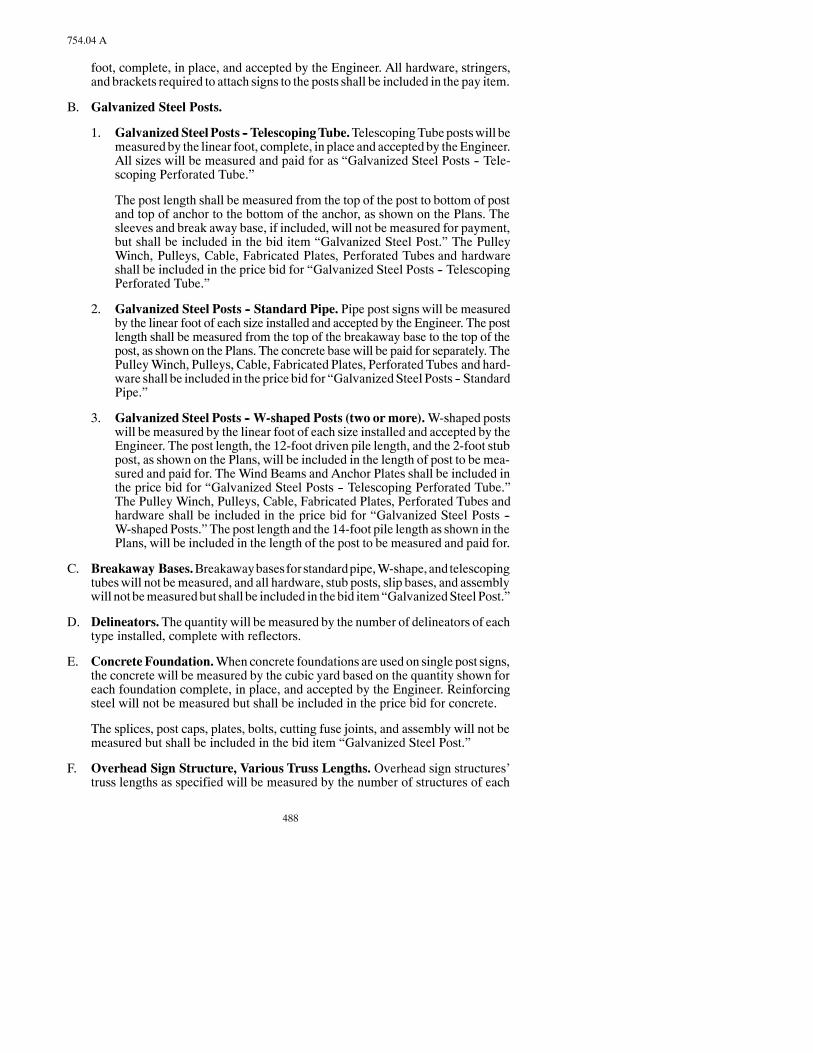
488
754.04 A
foot, complete, in place, and accepted by the Engineer. All hardware, stringers,and brackets required to attach signs to the posts shall be included in the pay item.
B. Galvanized Steel Posts.
1. GalvanizedSteelPosts -- TelescopingTube.TelescopingTubepostswill bemeasured by the linear foot, complete, in place and accepted by theEngineer.All sizes will be measured and paid for as “Galvanized Steel Posts -- Tele-scoping Perforated Tube.”
The post length shall be measured from the top of the post to bottom of postand top of anchor to the bottom of the anchor, as shown on the Plans. Thesleeves and break away base, if included, will not be measured for payment,but shall be included in the bid item “Galvanized Steel Post.” The PulleyWinch, Pulleys, Cable, Fabricated Plates, Perforated Tubes and hardwareshall be included in the price bid for “Galvanized Steel Posts -- TelescopingPerforated Tube.”
2. Galvanized Steel Posts -- Standard Pipe. Pipe post signs will be measuredby the linear foot of each size installed and accepted by the Engineer. The postlength shall be measured from the top of the breakaway base to the top of thepost, as shown on the Plans. The concrete base will be paid for separately. ThePulleyWinch, Pulleys, Cable, Fabricated Plates, Perforated Tubes and hard-ware shall be included in the price bid for “GalvanizedSteel Posts -- StandardPipe.”
3. Galvanized Steel Posts -- W-shaped Posts (two ormore).W-shaped postswill be measured by the linear foot of each size installed and accepted by theEngineer. The post length, the 12-foot driven pile length, and the 2-foot stubpost, as shown on the Plans, will be included in the length of post to be mea-sured and paid for. TheWind Beams and Anchor Plates shall be included inthe price bid for “Galvanized Steel Posts -- Telescoping Perforated Tube.”The Pulley Winch, Pulleys, Cable, Fabricated Plates, Perforated Tubes andhardware shall be included in the price bid for “Galvanized Steel Posts --W-shaped Posts.” The post length and the 14-foot pile length as shown in thePlans, will be included in the length of the post to be measured and paid for.
C. Breakaway Bases.Breakawaybasesforstandardpipe,W-shape, andtelescopingtubeswill not bemeasured, and all hardware, stub posts, slip bases, and assemblywill not bemeasuredbut shall be included in thebid item“GalvanizedSteelPost.”
D. Delineators.The quantity will bemeasured by the number of delineators of eachtype installed, complete with reflectors.
E. ConcreteFoundation.When concrete foundations are used on single post signs,the concrete will be measured by the cubic yard based on the quantity shown foreach foundation complete, in place, and accepted by the Engineer. Reinforcingsteel will not be measured but shall be included in the price bid for concrete.
The splices, post caps, plates, bolts, cutting fuse joints, and assembly will not bemeasured but shall be included in the bid item “Galvanized Steel Post.”
F. Overhead Sign Structure, Various Truss Lengths. Overhead sign structures’truss lengths as specified will be measured by the number of structures of each

489
754.05
length complete in place. The inspection walk (mounting hardware, grating,handrail, etc.) and hardware required for attaching of the inspection walk and as-sembling the structure shall be included in the price bid to perform this work.
G. Overhead Sign Structures on Bridges. Overhead sign structures on bridgeswill be measured by the number of structures in place. All hardware, supportingstructures attached to the bridge, inspection walk, and sign supporting structuresshall be included in the price bid to perform this work. The anchor bolts, nuts,washers, and tighteningas specifiedhereinwill not bepaid for separatelybut shallbe included in the price bid “Class AE Concrete -- Sign Foundations.”
H. Reset Sign Panels.Thequantity to be paid forwill bemeasured by the number oflocations atwhich a sign, or a sign assembly, has been reset. Signs and assemblieswill be measured in place and accepted by the Engineer.
I. Reset Sign Supports.Thequantity tobepaid forwill bemeasuredby thenumberof supports installed, complete, and accepted by the Engineer.
J. Removed Signs and Supports. Removed signs and supports will not be meas-ured for payment, butwill be included in other bid items. Cost of removal shall beincluded in the price bid for other items.
K. Remove Sign Foundations. The item “Remove Sign Foundations” will bemea-sured by the number of foundations and H-piling footings removed. The quanti-ties measured will be paid for at the Contract Unit Price, and will be full com-pensation for all labor, equipment, andmaterial necessary to complete the remov-al and disposal.
L. Revise Fuse Joint.The item“Revise Fuse Joint”will bemeasured by the numberof fuse joints revised.Thequantitiesmeasuredwill bepaid for at theContractUnitPrice and will be full compensation for all labor, equipment, and material neces-sary to complete the work.
M. Overlay Panel.The item “Overlay Panel” will bemeasured by the square foot ofpanel in place and accepted by theEngineer. The quantitiesmeasuredwill be paidfor at the Contract Unit Price and shall include all labor, equipment, andmaterialneeded to complete the work.
N. ResetMile Post. The item “Reset Mile Post” will be measured by the number oflocations atwhich amile post has been reset. The quantitiesmeasuredwill be paidfor at the contract price and shall be full compensation for all labor, equipment,and material necessary to complete the work.
754.05 BASIS OF PAYMENT.
Payment will be made at Contract Unit Prices for the following:
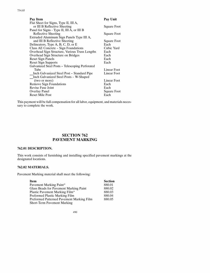
490
754.05
Pay Item Pay UnitFlat Sheet for Signs, Type II, III A,or III B Reflective Sheeting Square Foot
Panel for Signs - Type II, III A, or III BReflective Sheeting Square Foot
Extruded Aluminum Sign Panels Type III A,and III B Reflective Sheeting Square Foot
Delineators, Type A, B, C, D, or E EachClass AE Concrete -- Sign Foundations Cubic YardOverhead Sign Structure, Various Truss Lengths EachOverhead Sign Structure on Bridges EachReset Sign Panels EachReset Sign Supports EachGalvanized Steel Posts -- Telescoping Perforated
Tube Linear Foot__Inch Galvanized Steel Post -- Standard Pipe Linear Foot__Inch Galvanized Steel Posts -- W-Shaped
(two or more) Linear FootRemove Sign Foundations EachRevise Fuse Joint EachOverlay Panel Square FootReset Mile Post Each
This payment will be full compensation for all labor, equipment, andmaterials neces-sary to complete the work.
SECTION 762PAVEMENT MARKING
762.01 DESCRIPTION.
This work consists of furnishing and installing specified pavement markings at thedesignated locations.
762.02 MATERIALS.
Pavement Marking material shall meet the following:
Item SectionPavement Marking Paint* 880.01Glass Beads for Pavement Marking Paint 880.02Plastic Pavement Marking Film* 880.03Preformed Plastic Marking Film 880.04Preformed Patterned Pavement Marking Film 880.05Short-Term Pavement Marking

491
762.04 B.1
Paint 880.06Tape 880.06
Construction Zone Marking 880.07Raised Pavement Markers 880.08Epoxy Paint Pavement Marking 880.09
*Either “slow,” “medium,” or “fast dry” paint and either type of Plastic Marking Film may be used.
762.03 EQUIPMENT.
A. Paint Applicator.The equipment required to apply pavementmarking paint andglass beads shall be a self-propelled, pneumatic sprayingmachinewith atomizingnozzles capable of applying two4-inch to 8-inchwide lines at one time. The spraymechanismshall be operated byquick opening and closingvalves. The applicatorshall apply the materials at a rate specified in an even and uniform thickness withclearly defined edges. The applicator shall have reservoirs or tanks equippedwithagitators that keep thematerial in a smooth, evenmixture. Tanks shall have suffi-cient capacity to apply thematerials as specified.The applicator shall be equippedwith an automatic skip control device that applies a stripe of specified lengthwitha linear tolerance of 3 inches. The applicator shall be equippedwith a guide boomand be capable of retracing and applying materials to traffic markings in place.
Adequatehand-operatedequipment shall be required toplace thepavementmark-ings on areas not readily accessible to the pavement marking applicator.
Themachine shall be equippedwith a glass bead dispenser adjusted and synchro-nized with the paint applicator to distribute the reflectorizing spheres uniformlyon the painted line(s) using air pressure. The bead dispenser shall be equippedwith an automatic cutoff control, synchronizedwith the cutoff of the stripingma-terial.
B. Grooving Equipment. The grooving equipment shall utilize diamond bladesmounted on a self propelledmachine designed for grinding a recess into the pave-ment surface. The diamond blades shall be gangmounted on a floating headwithcontrols capable of providing uniform depth and alignment. The grooving equip-ment shall be capable of grooving a total width sufficient to install 4-inch widepavement marking tape in a single pass. The equipment shall not cause strain ordamage to the underlying surface of the pavement. Grooving equipment thatcauses ravels, aggregate fractures, spalling, or disturbance of the joints shall notbe permitted.
762.04 CONSTRUCTION REQUIREMENTS.
A. General.Aproject layout of the pavement striping andmarking shall be preparedand submitted to theEngineer for approval 48 hours before any installationwork.Type F paint shall be used for all painted centerline pavementmarking, other thanshort-term pavement marking.
B. Pavement Surface Preparation.
1. General.The pavement surface in the areawheremarkings are to be appliedshall becleananddry.Foreignmaterials, (i.e., dirt, petroleumproducts, paint,and curing compound) shall be removed from the pavement surface before

492
762.04 B.1
applying pavement marking. The amount of pavement moisture shall betestedby tapinga12-inchby12-inch (approximate) sheetof transparentplas-tic film, similar to “SaranWrap,” to the pavement. If moisture condenses onthe pavement side of the filmwithin 15minutes, the pavementmust be driedbefore installing pavement markings. The moisture test will not be requiredwhen water-based pavement marking paint is used.
2. Plastic Pavement Marking Film. The pavement surface shall be cleanedby sandblasting, power water spray, grinding, wire brushing, brooming,compressed air, or other methods to the satisfaction of the Engineer. NewPortland Cement concrete that has curing compound on it shall be sand-blasted.Costs associatedwith the requiredcleaning shall be included i thebiditem“PlasticPavementMarkingFilm.” If short-termorpermanentpavementmarking is encountered, removal will be paid for at the Contract Unit Pricebid forObliteration of PavementMarking.When no bid item is provided, thecost of removing the pavement marking will be paid for under Section104.03.
3. Preformed Patterned Pavement Marking Film. The preformed markingshall be capableof being adhered to asphalt concrete byapre-coatedpressuresensitive adhesive. A primer may be used to precondition the pavement sur-face.
4. Pavement Marking Paint. If theEngineer requires a cleaningmethodotherthan air pressure, the cost of cleaning will be paid for under Section104.03.
5. Short-TermPavementMarking.Short-termpavementmarking shall be anapplication of pavement marking paint, pavement marking tape, or raisedpavementmarkers. The surface preparation for application of the short-termpavement marking shall be the same as that required for permanent striping.
6. Grooved Pavement Markings.When specified in the Plans, the pavementsurface shall be grooved to make a recess in the pavement surface for thepavement marking film. The groove shall meet the following tolerances:
Depth 100 mils ±10 milsSmoothness ridges, within the groove, be
no more than 6 mils higherthan either adjacent valley
Width line width plus 1/2 inchLength line length plus 3 inches
per end of lineLine End Tapers 3 inches
For messages, the area grooved shall be the same area as the messages.Grooving a rectangular area to contain the message will not be allowed.Grooving shall meet the depth requirements specified above.
After grinding, the grooved slot shall be blown clean to remove any residueand loose materials prior to the installation of the pavement marking. Whenwet-grinding, the grooved slot shall immediately be pressure washed to re-move residue. If necessary, thegroovedslot shall beblownclean just aheadof

493
762.04 C.2
the pavementmarking installation. Thepavementmarkings shall be installedonacleandry surfacewithin24hoursof the initial grinding. If pavementmark-ing installation does not occur within 24 hours of the initial grinding, thegroove shall be sandblasted and blown clean to remove any dirt, oil, loosema-terial, or other contaminate prior to the installation of the pavement marking.
The pavementmarking film shall be installed as specified inSection 762.04D.
C. Traffic Control.
1. Signing. The Contractor shall erect and maintain sufficient devices (cones,signs, barricades) to protect the work area from traffic interference, trackingon or damage to the cleaned pavement, and the newly applied markings. Alldevices used to divert traffic from the work zone shall be designed to resistdisplacement by wind.
2. Traffic Movement. Traffic shall be maintained through the work area at alltimes according to the traffic control plan and Section 704. Flagpersons shallbe furnished when required.
Two-way traffic shall be maintained on two-lane roadways, and 1/2 of theroadway shall be open to traffic on multi-laned roadways at all times. Thecost to furnish, erect, andmaintain cones, signs, and barricades including thecost for flagging and shadow vehicles, shall be included in the cost of pave-ment marking.
PROTECTION VEHICLE WITH TRUCK MOUNTED ATTENUATIONDEVICE (TMA):
A protection (shadow) vehiclewith a truckmounted attenuation device shallbe provided by the contractor to protect personnel and equipment fromdam-age during mobile operations. The protection (shadow) vehicle will not berequired on construction projects when the advance warning signs are inplace.
Truck-mounted attenuation device shall meet the test requirements ofNCHRP Report 350 test level TL-3.
Theprotectionvehicle equippedwith theTMAshall have aminimumweightof10,000 poundsor theminimumweight recommendedby themanufacturerof the TMA.
The protection vehicle shall be equipped with seat and shoulder belts alongwith a head cushion.
Theprotectionvehicle shall have an advancewarning flashing or sequencingarrow panel conforming to Section 704.02 M and the Manual on UniformTraffic Control Devices.
The positioning of the protection vehicle with the TMA in relation toconstruction activities will be as shown in the Plans.
The cost of furnishing the protection vehicle with the TMA shall not be bidseparately, but shall be included in the price bid for the item “PavementMarkings.”

494
762.04 C.3
3. Time Period for Control. Necessary traffic control devices shall be prop-erly placed and in operation before construction is allowed to start. The de-vices shall be kept current and placed only in the areas of actual work activi-ties. Traffic control devices shall be kept in place until the Engineer approvestheir removal after the pavement marking has dried, and is determined to beready for traffic.
4. Operational Precautions. Equipment shall not be prepared, filled, orcleaned, nor shall any equipment ormaterial be stored on the roadway. Theseoperations shall be conducted off the pavement without interfering with orendangering traffic according to Section 107.05 A.
D. Pavement Marking Application.
1. Pavement Marking Paint and Glass Beads.
a. Method of Application. Pavement marking paint and glass beads shallbe applied separatelybymachine.Wheremachine application in anodd-shaped area is not feasible, hand application is permitted.
b. Application Dates and Temperatures. Pavement marking paint andbeads (except for temporary stripe) shall not be appliedbeforeMay1norafter October 1 except upon written permission of the Engineer. Pave-mentmarkingpaint shall be appliedonlyduringdaylight hourswhen theair and pavement surface temperatures are 40°F. orwarmerwhen apply-ing solvent based paint or 45°F. or warmer when applying water basedpaint. The paint shall not be applied when the air and pavement surfacetemperatures are expected or forecasted to be colder (lower) than theminimum application temperature.
New asphalt pavement shall be allowed to cool to a maximum tempera-ture of 125°F. and be given aminimum curing period of four hours priorto applying permanent striping.
c. Rate of Application. One gallon of paint shall cover a 4-inch widestripe for a length of 280 to 320 feet, depending upon pavement surfacetexture. Short-term pavement markings shall have a thickness of 8 milswet when permanent marking is epoxy paint. The paint shall not be di-luted, but a small amount of naphtha thinner may be used to flush outpaint containers. Glass beads shall be evenly distributed over the wetpaint stripe at a rate of at least 6poundsper gallonof paint.Beads shall beappliedusinganautomaticpressuredispenser. If theapplication ratesarenot within the requirements, the marking application shall be stoppeduntil corrections are made.
d. Short-Term Pavement Marking. Pavement marking paint and beadsapplied as short-term pavement marking shall be applied only duringdaylight hours.Application shall bemade in a4-inchwidthanda10-footlength with unpainted gaps of 30 feet. The no-passing zone markingsshall be made in a 4-inch width and a length as required to cover the no-passing zones. Thepaint andbeads shall be applied as required and at therate specified in Section 762.04 D.1.c. Short-term pavement markingapplied to the center line shall be applied to the full length of the bitumi-

495
762.04 D.1.e
nous course andmilled surface before sunset on the sameday thework isaccomplished. Pavingormillingoperations shall not resume if the short-term pavement marking has not been replaced as required.
On the final lift, new asphalt pavements shall be allowed to cool to amaximum temperature of 125°F. before applying short-term pavementmarking paint.
Short-term pavement marking on the top lift shall be carefully placedwith exact alignment and spacing so that the permanent striping willmatch when applied. Errors in alignment and spacing shall be correctedat theContractor’s expense, or removed just before the installationof thepermanent striping.
When Type NR (Not Easily Removable) short-term pavement markingis specified, pavement marking paint and beads may be used in lieu ofType NR construction zone marking film.
e. Short-Term Pavement Marking -- Seal Coat Projects. Short-termpavementmarking for seal coat projects shall consist of pavementmark-ing paint and beads. Before sealing operations, spotting tabs shall be in-stalled every200 feet along the centerline and tabs shall alsobeplaced tomark the beginning and end of the no-passing zones. The spotting tabsshall be removedbycutting the tabs flushwith the roadwaysurface.Tabsshall not be pulled out. The cost of the spotting tabs and their installationand removal shall be included in the bid item “Short-Term PavementMarking.”
The short-term pavement marking shall be applied before sunset eachday to the full length of the roadway that received the bitumen and covercoat material that day. Seal coat operations shall not resume if the short-term pavement marking is not in place as required. The broken line atcenterline of two-lane, two-way roadways (yellow) or between lanes ofmulti-laned roadways (white) shall be 4 inches wide and 10 feet longfollowed by a 30-foot unpainted gap. The solid line barrier stripe (yel-low) in no-passing zones shall be 4 inches wide, and the length shall bethat required to cover the entire no-passing zone. Before applying thepaint andbeads, the areas to receive the striping shallbe lightlybroomed.
If the in-place short-term pavement marking has become obscured andhas lost its required visibility due to being covered, or partially covered,by cover coat or blotter material, thematerial shall be removed from thestriped areas by light brooming or compressed air before sunset. Dam-age to the cover coatmaterial and striping resulting fromthe removal op-eration shall be corrected at the Contractor’s expense.
The short-term pavement marking shall be carefully placed with exactalignment and spacing so that the permanent stripingmatches when ap-plied. Errors in alignment and spacing shall be corrected at the Contrac-tor’s expense.
One gallon of paint shall cover a 4-inchwide stripe for a length of 200 to240 feet, asdirectedby theEngineer.Glassbeads shall be evenlydistrib-uted over thewet paint at the rate of at least 6 pounds per gallon of paint.

496
762.04 D.1.f
f. Tolerances.
(1) The length of the painted stripe shall not varymore than plus or mi-nus 3 inches from the prescribed length.
(2) The width of the painted stripe shall not vary more than plus or mi-nus 1/2 inch from the prescribed width.
(3) The length of the painted segment and gap shall not varymore than6 inches in a 40-foot cycle.
(4) The tolerance from the proper alignment shall not vary more thanplus or minus 2 inches.
(5) Dashed lines that are painted over existing dashed lines shall beginwithin 6 inches of the beginning of the existing line, unless other-wise directed by the Engineer.
2. Plastic Pavement Marking Film.
a. General. Plastic pavement marking film applied as a permanent pave-mentmarking shall not be applied before June 1nor after September 1ofany year. The permanent marking film shall not be applied when thepavement surface temperature is 50°F. or colder, nor shall the film beplaced over painted markings. The pavement surface and the markingfilm shall be prepared for installation as required for the type of filmused. The film shall be lap or butt spliced when required to jointwo lengths of film, and the film shall be cut at open joints or cracks inthe pavement. The cut ends shall be firmly tamped in place.
b. Plastic Pavement Marking Film Application. Application of plasticpavementmarking film,whetherbycontact cementormechanical appli-cation, shall be made using the manufacturer’s recommendation.
c. Plastic Pavement Marking Film Rolled in Hot Asphalt. The plasticpavement marking shall be rolled into the hot asphalt surface. The con-tractor shall arrange to have the plastic pavementmarkingsplacedon thehot asphalt in the position shown on the plans at the time of final asphaltrolling operations. The plastic pavement markings shall receive at leastone rolling. The requirements not allowing installation prior to June 1 orafter September 1 will not apply. The temperature of the hot asphaltpavement during application shall be as specified by the manufacturer.The cost of placing and rolling the pavement markings into the hot as-phalt pavement shall be included in the price bid for the item “PlasticPavement Marking Film Line or Message.”
d. Short-Term Pavement Marking. Pavement marking tape applied asshort-term pavement marking shall conform with the requirement forapplication of pavement marking tape. The tape shall be applied on thecenter line in a 4-inch width and a 10-foot length with a gap of 30 feet.Short TermType R and Short TermTypeR-WR shall be installedwhereair and pavement temperatures are 50°F and are expected to remain at orcontinue to increase above 50°F. If either temperature falls below 50°F,

497
762.04 D.3.c
short-term paint shall be substituted and paid for as “Short Term INLine -- Type NR.” Removal of the paint will be paid for as “Obliterationof PvmtMk.” The short-term paint substitution shall cease and installa-tion of “Short Term IN Line -- Type NR” shall proceed as soon as airand pavement temperatures reach 50°F. The no-passing zone markingsshall be made in a 4-inch width and a length, as required, to cover theno-passing zone. The short-term pavement marking shall be applied tothe full length of the bituminous pavement and milled surface placedeach day, and shall be completed before sunset each day. Paving andmilling operations shall not resume if the striping is not in place as re-quired.
Type R--Removal Retroreflective Film, Type R--WR--Removable WetReflective Film, and Type NR Retroreflective Pavement Striping (noteasily removed) construction zone marking film shall be applied wherespecified. The film required shall be applied as specified for pavementmarking film.
The Contractor shall remove the Type R or Type R--WR constructionzonemarking filmwhen required in theContract or directedby theEngi-neer.
Pavement marking paint with beads may be used in lieu of Type NRconstruction zone marking film for short-term pavement marking.
3. Preformed Patterned Pavement Marking Film.
a. General. Preformed Patterned pavement marking film applied as a per-manent pavement marking shall not be applied before June 1 nor afterSeptember 1 of any year. The permanent marking film shall not be ap-pliedwhen thepavement surface temperature is50°F. or colder, nor shallthe filmbe placed over paintedmarkings. The pavement surface shall beprepared for installation as required by the manufacturer. The film shallbe lap or butt spliced when required to join two lengths of film, and thefilm shall be cut at open joints or cracks in the pavement. The cut endsshall be firmly tamped in place.
b. Preformed Patterned Pavement Marking Film Application.Appli-cationofpreformedpatternedpavementmarking filmshall beaccordingto the manufacturer’s recommendation.
c. Preformed Patterned Pavement Marking Film Rolled in Hot As-phalt. The Contractor shall provide Preformed Patterned PavementMarking Film for longitudinal lines and messages. The preformed pat-ternedpavementmarking shall be rolled into the hot asphalt surface.TheContractor shall arrange to have the preformed patterned pavementmarkings placed on the hot asphalt in the position shown on the plans atthe time of the final rolling operations. The preformed patterned pave-mentmarkings shall be rolled at least twice. The requirements not allow-ing installation prior to June1 or after September 1 will not apply. Thetemperature of the hot asphalt pavement during application shall be asspecified by the manufacturer. The cost of placing and rolling the pave-ment markings into the hot asphalt pavement shall be included in the

498
762.04 D.3.c
price bid for the item “Preformed Patterned Pavement Marking Line orMessage.”
4. Pavement Marking Sheeting (Pressure Sensitive). This marking shall beapplied as required in the Contract or by hand or mechanical methods to apavement surfacepreparedas required for all pavementmarking.Thedeline-ated position on the pavement surface shall be primed using the sheetingmanufacturer’s recommendations. The primed surface shall be air dried forone to two minutes before applying the sheeting. Mechanical applicationconforming to the sheeting manufacturer’s recommendations shall be used,unless machine application is impractical. Sheeting shall be inlaid into thepavement by roller when the pavement is warm enough to accept the pave-ment marking sheeting without damaging the sheeting.
5. Raised Pavement Markers. Raised pavement markers shall be reflec-torized. Broken lane lines and center lines on two-lane two-way roadwaysshall consist of fourmarkerson3.33-foot centerswith a30-foot gap.Markersused for solid lines shall be spacedon5-foot centers.Raisedpavementmarkersused indouble solid lines shall beplaced sideby side separatedbya4-inchgap.
New concrete pavement (pavement that has had no traffic over it for awinterseason) shall have markers placed on 5-foot centers for all solid lines.
6. Epoxy Paint and Glass Beads.
a. Description. The work shall consist of furnishing and installing reflec-torized white and yellow two-component, 100 percent solids epoxypavement markings. Applications are lines, legends, symbols, cross-walksandstop linesplaced inaccordancewith thePlansor asdirectedbytheEngineer.Upon curing, thematerials produce pavementmarkings ofspecified thickness,widthand retroreflectivity that resistwear fromhightraffic volumes for several years. During darkness and weather permit-ting, yellow markings shall be readily distinguishable from white mark-ings.
b. General. Pavementmarkings shall be placed in accordancewith the de-tails shown in the Plans and the control points established by the Engi-neer.
Pavement surfaces, upon which epoxymarkings are to be applied, shallbe cleaned as per the manufacturer’s recommendation at the discretionof the Engineer.
New Portland Cement Concrete surfaces and existing pavement mark-ings shall be cleaned by sandblasting, shotblasting, grinding, or water-blasting to remove all surface treatments, laitance, or existing pavementmarkings to the satisfaction of the Engineer and manufacturer’s recom-mendations.
Bituminous seal coatsmust be completely cured and free of loose aggre-gate. All pavements shall be brushedwith a rotary broom (nonmetallic).Additional cleaning may be required to provide a surface that is free ofoil, grease, mud, dirt, existing markings that may be loose, dust, andother deleteriousmaterial prior to the applicationof the epoxymarkings.
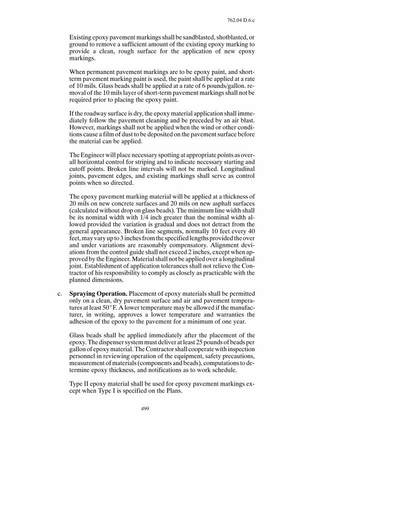
499
762.04 D.6.c
Existing epoxy pavementmarkings shall be sandblasted, shotblasted, orground to remove a sufficient amount of the existing epoxy marking toprovide a clean, rough surface for the application of new epoxymarkings.
When permanent pavement markings are to be epoxy paint, and short-term pavement marking paint is used, the paint shall be applied at a rateof 10 mils. Glass beads shall be applied at a rate of 6 pounds/gallon. re-moval of the 10mils layer of short-termpavementmarkings shall not berequired prior to placing the epoxy paint.
If the roadway surface is dry, the epoxymaterial application shall imme-diately follow the pavement cleaning and be preceded by an air blast.However, markings shall not be applied when the wind or other condi-tions cause a film of dust to be deposited on the pavement surface beforethe material can be applied.
TheEngineerwill placenecessary spotting at appropriate points asover-all horizontal control for striping and to indicate necessary starting andcutoff points. Broken line intervals will not be marked. Longitudinaljoints, pavement edges, and existing markings shall serve as controlpoints when so directed.
The epoxy pavement marking material will be applied at a thickness of20 mils on new concrete surfaces and 20 mils on new asphalt surfaces(calculatedwithout drop on glass beads). Theminimum line width shallbe its nominal width with 1/4 inch greater than the nominal width al-lowed provided the variation is gradual and does not detract from thegeneral appearance. Broken line segments, normally 10 feet every 40feet,mayvaryup to3 inches fromthespecified lengthsprovided theoverand under variations are reasonably compensatory. Alignment devi-ations from the control guide shall not exceed 2 inches, except when ap-proved by theEngineer.Material shall not be applied over a longitudinaljoint. Establishment of application tolerances shall not relieve the Con-tractor of his responsibility to comply as closely as practicable with theplanned dimensions.
c. Spraying Operation. Placement of epoxy materials shall be permittedonly on a clean, dry pavement surface and air and pavement tempera-tures at least 50_F. A lower temperaturemay be allowed if themanufac-turer, in writing, approves a lower temperature and warranties theadhesion of the epoxy to the pavement for a minimum of one year.
Glass beads shall be applied immediately after the placement of theepoxy.Thedispenser systemmust deliver at least 25poundsof beadspergallonof epoxymaterial.TheContractor shall cooperatewith inspectionpersonnel in reviewing operation of the equipment, safety precautions,measurement ofmaterials (components and beads), computations to de-termine epoxy thickness, and notifications as to work schedule.
Type II epoxy material shall be used for epoxy pavement markings ex-cept when Type I is specified on the Plans.
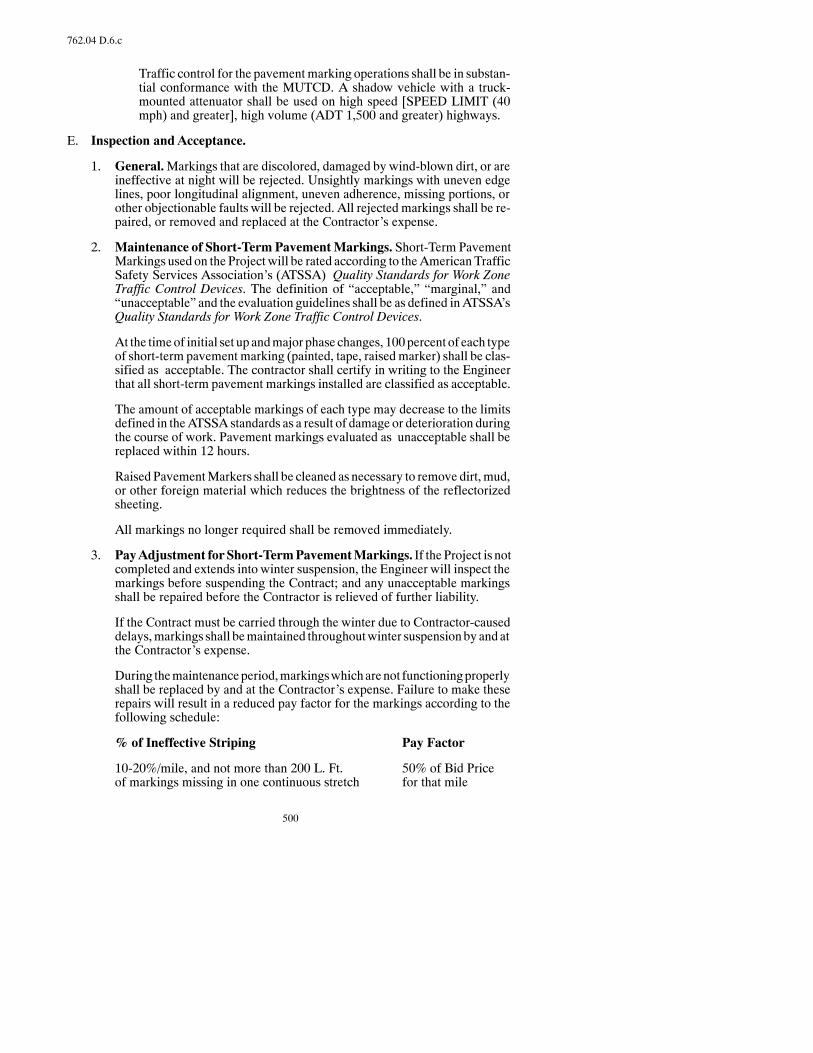
500
762.04 D.6.c
Traffic control for the pavementmarking operations shall be in substan-tial conformance with the MUTCD. A shadow vehicle with a truck-mounted attenuator shall be used on high speed [SPEED LIMIT (40mph) and greater], high volume (ADT 1,500 and greater) highways.
E. Inspection and Acceptance.
1. General.Markings that are discolored, damaged by wind-blown dirt, or areineffective at night will be rejected. Unsightly markings with uneven edgelines, poor longitudinal alignment, uneven adherence, missing portions, orother objectionable faults will be rejected. All rejected markings shall be re-paired, or removed and replaced at the Contractor’s expense.
2. Maintenance of Short-Term PavementMarkings. Short-Term PavementMarkings used on the Project will be rated according to theAmericanTrafficSafety Services Association’s (ATSSA) Quality Standards for Work ZoneTraffic Control Devices. The definition of “acceptable,” “marginal,” and“unacceptable” and the evaluation guidelines shall be as defined inATSSA’sQuality Standards for Work Zone Traffic Control Devices.
At the timeof initial set up andmajor phase changes, 100percent of each typeof short-term pavement marking (painted, tape, raisedmarker) shall be clas-sified as acceptable. The contractor shall certify in writing to the Engineerthat all short-term pavement markings installed are classified as acceptable.
The amount of acceptable markings of each type may decrease to the limitsdefined in theATSSA standards as a result of damage or deterioration duringthe course of work. Pavement markings evaluated as unacceptable shall bereplaced within 12 hours.
Raised PavementMarkers shall be cleaned as necessary to remove dirt,mud,or other foreign material which reduces the brightness of the reflectorizedsheeting.
All markings no longer required shall be removed immediately.
3. PayAdjustment forShort-TermPavementMarkings. If the Project is notcompleted and extends into winter suspension, the Engineer will inspect themarkings before suspending the Contract; and any unacceptable markingsshall be repaired before the Contractor is relieved of further liability.
If the Contract must be carried through the winter due to Contractor-causeddelays,markings shall bemaintained throughoutwinter suspensionby andatthe Contractor’s expense.
During themaintenanceperiod,markingswhicharenot functioningproperlyshall be replaced by and at the Contractor’s expense. Failure to make theserepairs will result in a reduced pay factor for the markings according to thefollowing schedule:
% of Ineffective Striping Pay Factor
10-20%/mile, and not more than 200 L. Ft. 50% of Bid Priceof markings missing in one continuous stretch for that mile
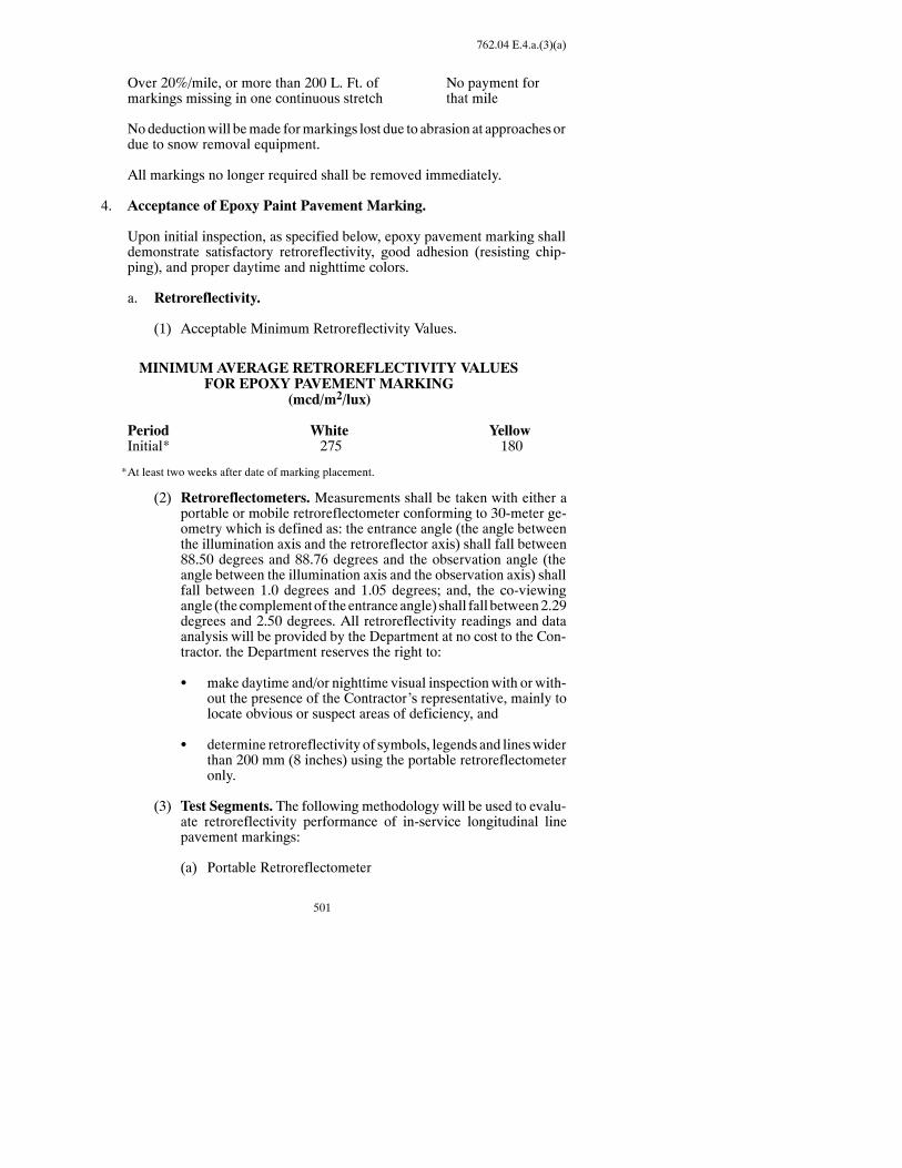
501
762.04 E.4.a.(3)(a)
Over 20%/mile, or more than 200 L. Ft. of No payment formarkings missing in one continuous stretch that mile
Nodeductionwill bemade formarkings lost due to abrasion at approachesordue to snow removal equipment.
All markings no longer required shall be removed immediately.
4. Acceptance of Epoxy Paint Pavement Marking.
Upon initial inspection, as specified below, epoxy pavement marking shalldemonstrate satisfactory retroreflectivity, good adhesion (resisting chip-ping), and proper daytime and nighttime colors.
a. Retroreflectivity.
(1) Acceptable Minimum Retroreflectivity Values.
MINIMUM AVERAGE RETROREFLECTIVITY VALUESFOR EPOXY PAVEMENT MARKING
(mcd/m2/lux)
Period White YellowInitial* 275 180
*At least two weeks after date of marking placement.
(2) Retroreflectometers. Measurements shall be taken with either aportable or mobile retroreflectometer conforming to 30-meter ge-ometry which is defined as: the entrance angle (the angle betweenthe illumination axis and the retroreflector axis) shall fall between88.50 degrees and 88.76 degrees and the observation angle (theangle between the illumination axis and the observation axis) shallfall between 1.0 degrees and 1.05 degrees; and, the co-viewingangle (the complementof theentranceangle) shall fall between2.29degrees and 2.50 degrees. All retroreflectivity readings and dataanalysis will be provided by the Department at no cost to the Con-tractor. the Department reserves the right to:
S make daytime and/or nighttime visual inspectionwith or with-out the presence of the Contractor’s representative, mainly tolocate obvious or suspect areas of deficiency, and
S determine retroreflectivity of symbols, legends and lineswiderthan 200 mm (8 inches) using the portable retroreflectometeronly.
(3) Test Segments. The following methodology will be used to evalu-ate retroreflectivity performance of in-service longitudinal linepavement markings:
(a) Portable Retroreflectometer

502
762.04 E.4.a.(3)(a)1)
1) The roadway1 shall be divided into consecutive test seg-ments2. A test segment is defined as twomiles in length.Atest segment shall have one test location per line type.3
2) For each type of solid line, the number of readings per testlocation are as follows:
Roadway 0--15 miles in length: five reading per test loca-tionRoadway>15miles in length: three readings per test loca-tion
3) For solid lines, take readings 5 feet apart.
4) For broken lines (skip lines), test two lines per test loca-tion. Take two readings from each line. Take readings 30inches from each end of the line.
5) For 10 percent of eachmessage type, take five readings oneach message line; for 10 percent of each symbol type,take five readings on each symbol.
6) Upon completion of the evaluation, regardless of the re-sults, additional test segmentsmaybeorderedby theEngi-neer.
1Roadway: As used here, means that portion of a street or highway ordinarily usedfor vehicular traffic. In the event a street or highway includes two or more separateroadways, the term roadway shall refer to each roadway separately.
2Test Segments: Areas of a roadway chosen for measuring retroreflectivity of theline types.
3Line Type: Longitudinal lines of the same color and function. For example, whiteand yellow edge lines are each a line type.
(b) Mobile Retroreflectometer
1) Calibration of the instruments shall be in accordance withthe manufacturer’s instructions.
2) Retroreflectivity shall be measured at a minimum rate of20 percent of each test segment by line type.
3) Should anothermobile unit be available, themaximumac-ceptable deviation formeasurementsmade by the two dif-ferent instruments of the same manufacturer and for thesame roadway length shall be 10 percent.
4) Repeatability for the given mobile unit shall be 6 per-cent.
5) Upon completion of the evaluation, regardless of the re-sults, additional test segmentsmaybeorderedby theEngi-neer.
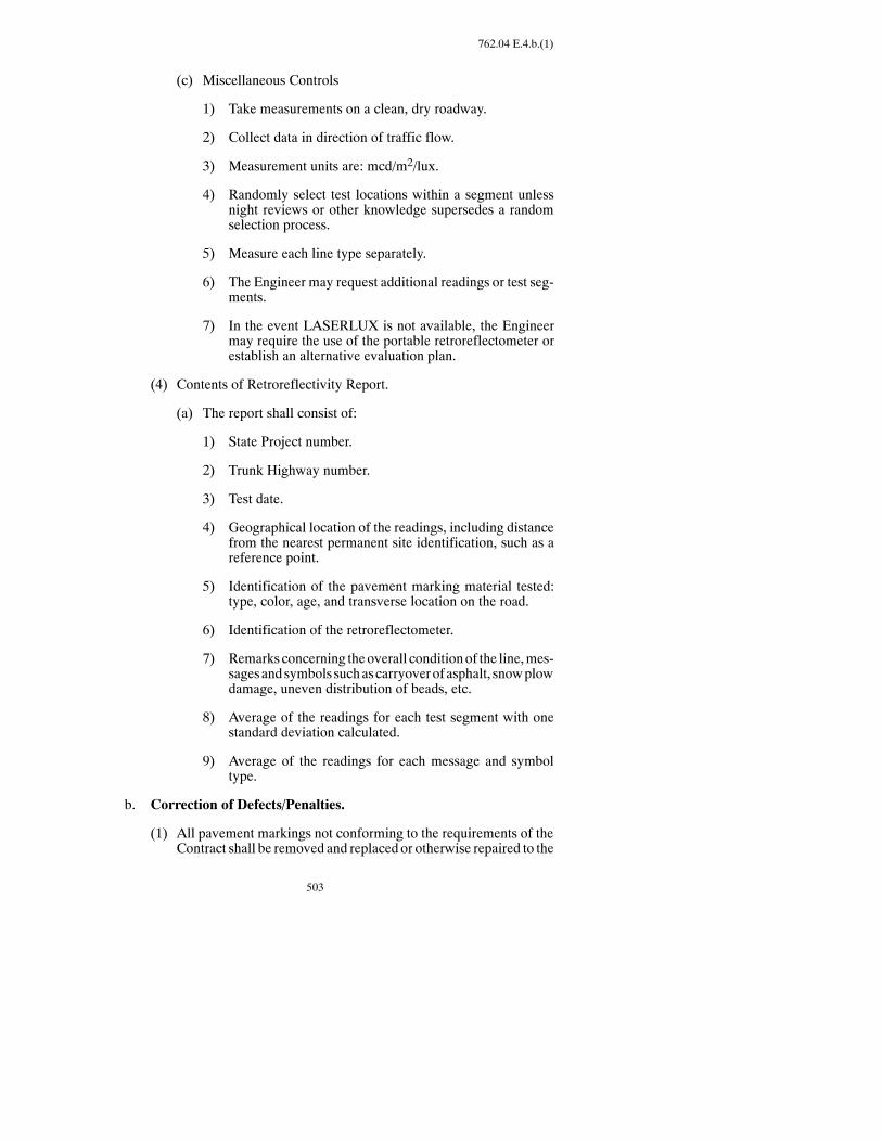
503
762.04 E.4.b.(1)
(c) Miscellaneous Controls
1) Take measurements on a clean, dry roadway.
2) Collect data in direction of traffic flow.
3) Measurement units are: mcd/m2/lux.
4) Randomly select test locations within a segment unlessnight reviews or other knowledge supersedes a randomselection process.
5) Measure each line type separately.
6) The Engineer may request additional readings or test seg-ments.
7) In the event LASERLUX is not available, the Engineermay require the use of the portable retroreflectometer orestablish an alternative evaluation plan.
(4) Contents of Retroreflectivity Report.
(a) The report shall consist of:
1) State Project number.
2) Trunk Highway number.
3) Test date.
4) Geographical location of the readings, including distancefrom the nearest permanent site identification, such as areference point.
5) Identification of the pavement marking material tested:type, color, age, and transverse location on the road.
6) Identification of the retroreflectometer.
7) Remarks concerning theoverall conditionof the line,mes-sagesandsymbols suchascarryoverofasphalt, snowplowdamage, uneven distribution of beads, etc.
8) Average of the readings for each test segment with onestandard deviation calculated.
9) Average of the readings for each message and symboltype.
b. Correction of Defects/Penalties.
(1) All pavement markings not conforming to the requirements of theContract shall be removed and replaced or otherwise repaired to the
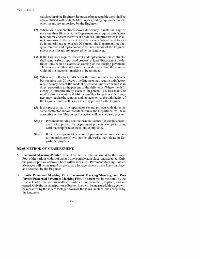
504
762.04 E.4.b.(1)
satisfactionof theEngineer.Removal of unacceptablework shall beaccomplished with suitable blasting or grinding equipment unlessother means are authorized by the Engineer.
(2) Where yield computations show a deficiency in material usage ofnot more than 20 percent, the Department may require satisfactoryrepair or may accept the work at a reduced unit price which is in di-rect proportion to the percent of the deficiency.Where the deficien-cy in material usage exceeds 20 percent, the Department may re-quire removal and replacement to the satisfaction of the Engineerunless other means are approved by the Engineer.
(3) If the Engineer requires removal and replacement, the contractorshall remove (by an approved process) at least 90 percent of the de-ficient line, with no excessive scarring of the existing pavement.The removal width shall be one inch wider all around the nominalwidth of the pavement marking to be removed.
(4) Where retroreflectivity falls below theminimum acceptable levels,but notmore than 20 percent, the Engineermay require satisfactoryrepair or may accept the work at a reduced unit price which is indirect proportion to the percent of the deficiency. Where the defi-ciency in retroreflectivity exceeds 20 percent (i.e. less than 220mcd/m2/lux for white and 144 mcd/m2/lux for yellow), the Engi-neer may require the removal and replacement to the satisfaction ofthe Engineer unless other means are approved by the Engineer.
(5) If this process has to be repeated on several projects with either thesame contractor and/or manufacturer(s), the Department will takecorrective action. This corrective action will be a two step process:
Step 1: Pavement marking contractor/manufacturer(s) will be consid-ered not approved for Department projects, except to bringworkmanship/product back into compliance.
Step 2: If the first step cannot be attained, pavement marking contrac-tor/manufacturer(s) will not be allowed to participate in De-partment projects.
762.05 METHOD OF MEASUREMENT.
A. Pavement Marking-Painted Line. This item will be measured by the LinearFoot of the various widths of painted line, complete, in place, and accepted. Onlythe painted portion of broken lineswill bemeasured. PavementMarking-PaintedMessages will be measured by the square footage shown on the Plans, in place,and accepted by the Engineer.
B. Plastic Pavement Marking Film, Pavement Marking Sheeting, and Pre-formed Patterned PavementMarking Film.This itemwill bemeasured by theLinear Foot of the various widths of installed line, complete, in place, and ac-cepted.Only the installed portionof broken lineswill bemeasured.Messageswillbe measured by the square footage shown on the Plans, in place, and accepted bythe Engineer.
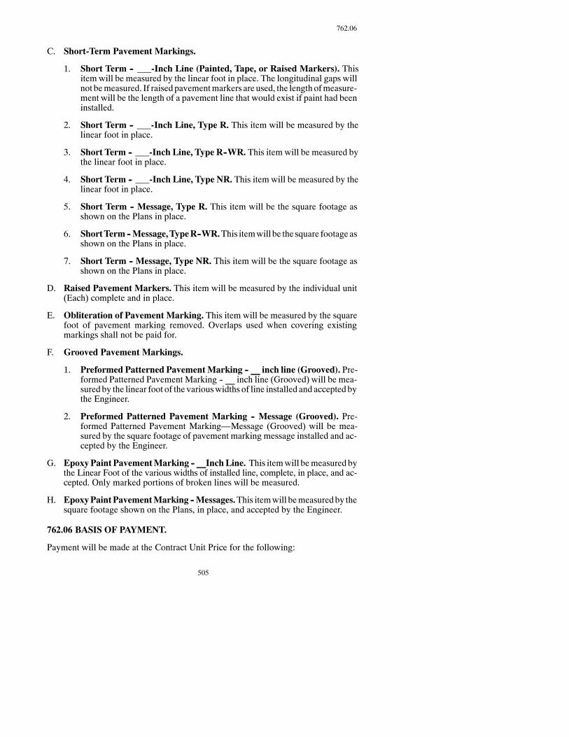
505
762.06
C. Short-Term Pavement Markings.
1. Short Term -- -Inch Line (Painted, Tape, or Raised Markers). Thisitem will be measured by the linear foot in place. The longitudinal gaps willnot bemeasured. If raised pavementmarkers are used, the length ofmeasure-ment will be the length of a pavement line that would exist if paint had beeninstalled.
2. Short Term -- -Inch Line, Type R. This item will be measured by thelinear foot in place.
3. Short Term -- -Inch Line, Type R--WR. This item will be measured bythe linear foot in place.
4. Short Term -- -Inch Line, Type NR. This item will be measured by thelinear foot in place.
5. Short Term -- Message, Type R. This item will be the square footage asshown on the Plans in place.
6. ShortTerm --Message,TypeR--WR.This itemwill be the square footageasshown on the Plans in place.
7. Short Term -- Message, Type NR. This item will be the square footage asshown on the Plans in place.
D. Raised Pavement Markers. This item will be measured by the individual unit(Each) complete and in place.
E. Obliteration of Pavement Marking. This item will be measured by the squarefoot of pavement marking removed. Overlaps used when covering existingmarkings shall not be paid for.
F. Grooved Pavement Markings.
1. Preformed Patterned PavementMarking -- __ inch line (Grooved). Pre-formed Patterned Pavement Marking -- __ inch line (Grooved) will be mea-sured by the linear foot of the variouswidths of line installed and accepted bythe Engineer.
2. Preformed Patterned Pavement Marking -- Message (Grooved). Pre-formed Patterned Pavement Marking—Message (Grooved) will be mea-sured by the square footage of pavement marking message installed and ac-cepted by the Engineer.
G. EpoxyPaint PavementMarking -- __InchLine. This itemwill bemeasured bythe Linear Foot of the various widths of installed line, complete, in place, and ac-cepted. Only marked portions of broken lines will be measured.
H. EpoxyPaintPavementMarking --Messages.This itemwill bemeasuredby thesquare footage shown on the Plans, in place, and accepted by the Engineer.
762.06 BASIS OF PAYMENT.
Payment will be made at the Contract Unit Price for the following:
506
762.06
Pay Item Pay UnitPavement Marking Painted - INCH LINE Linear FootPavement Marking Painted -- Message Square FootPlastic Pavement Marking Film - INCH LINE Linear FootPlastic Pavement Marking Film -- Message Square FootPreformed Patterned Pavement Marking - INCH LINE Linear FootPreformed Patterned Pavement Marking -- Message Square FootPavement Marking Sheeting - INCH LINE Linear FootPavement Marking Sheeting -- Message Square FootShort Term -- -INCH LINE (Painted, Tape, or Raised Markers) Linear FootShort Term -- -INCH LINE, Type R Linear FootShort Term -- -INCH LINE, Type R--WR Linear FootShort Term -- -INCH LINE, Type NR Linear FootShort Term -- Message, Type R Square FootShort Term -- Message, Type R--WR Linear FootShort Term -- Message, Type NR Square FootShort Term -- Painted Line (Seal Jobs) Linear FootRaised Pavement Markers EachObliteration of Pavement Marking Square FootPreformed Patterned Pvmt. Marking -- __ INCH LINE (Grooved) Linear FootPreformed Patterned Pvmt. Marking -- Message (Grooved) Square FootPreformed Plastic -- -INCH LINE Linear FootEpoxy Paint Pavement Markings -- INCH LINE Linear FootEpoxy Paint Pavement Marking -- Message Square Foot
This payment will be full compensation for all labor, equipment, andmaterials neces-sary to complete the work.
The price bid for TypeRmarking film shall include the cost of installation and removal.
SECTION 764GUARDRAIL
764.01 DESCRIPTION.
This work consists of installing, removing, and resetting guardrail and box beamme-dian barrier.
764.02 MATERIALS.
Materials shall meet the following:
Item SectionConcrete, Class AE 802Reinforcing Steel 836.02 ACable Guardrail, Wire Rope, and Fittings 862.02

507
764.03 A
W-Beam Guardrail, Guardrail Units, and Fittings 862.03Treated Wood Guardrail Posts 862.04Steel Guardrail Posts 862.05Box Beam 862.06
764.03 CONSTRUCTION REQUIREMENTS.
A. General. The guardrail shall be installed to produce a smooth continuous linewith uniform height.
Guardrail posts shall be installed where staked and to the depth specified. Postsshall be set plumb with the front faces uniformly aligned.
Postsmaybedrivenusing a suitable head toprevent damage to the post.Damagedposts shall be replaced at the Contractor’s expense. The post being replaced shallbe installed by drilling. A post capmust be usedwhenminor vertical adjustmentsare made using a sledgehammer or maul.
Whenposts are installed in auguredor dugholes, theholes shall bebackfilledwithapprovedmaterial and the surplus excavatedmaterial disposed of at locations ac-ceptable to theEngineer.Thebackfill shall beplacedandcompacted in8-inch lay-ers, using a mechanical tamper with an appropriate sized tamping head withoutdisplacing the post alignment.
Drilling post holes in pavement shall be done without damage to the surroundingpavement. The proposed drillingmethod and equipment shall be approved by theEngineer before work is begun. Backfill shall be as described above except thatthe final 8 inches of backfill shall be bituminous material approved by the Engi-neer.
Underground utilities or structures shall not be damaged when installing posts oranchor units.Anydamage toutilities or structures shall be repaired at theContrac-tor’s expense according to Section 105.03.
Concrete pedestals shall be cast in place.
No burning or weldingwill be permitted in the field or after thematerial has beengalvanized. Only drilling will be allowed on the work site.
Galvanized surface that has been damaged in transporting, handling, or erectingshall be repaired at the Contractor’s expense. The damaged area shall be thor-oughly cleanedbywirebrushingandpaintedwith twocoatsofmatchingzinc-richpaint.
All bolts andnuts, except adjustment bolts, shall bedrawn tight.Bolts shall extendat least 1/4 inch but no more than 1 inch beyond the nuts.
Guardrailmaterials laidout along the shoulder at thework site andnot installedbythe end of the work day, shall be removed according to Section 107.05 A. Postend, beam, and end terminal sections shall be erected in a continuous operationwithin each individual runof guardrail and each individual run shall be completedthe sameday. Incomplete guardrail installation shall bemarkedbyvertical panels,drums, and reflectorized plates at a 50-foot maximum spacing.
508
764.03 A
Reflectorized plates shall be new and shall be furnished and installed as shown inthe Contract.
On projects where the roadway will be open to traffic during construction, delin-eator drums shall be installed at 25-foot intervals adjacent to the work site at eachlocation where existing guardrail is removed, or where no guardrail previouslyexisted, or at guardrail extensions. The delineator drums shall remain in place un-til the installation of the guardrail at that location is complete and accepted by theEngineer.
Parking of equipment and vehicles, and the storage of materials, shall meet Sec-tion 107.05 A.
At bridge connections, the attachment brackets shall be fabricated so the attach-ment bolt holes can be field drilled to fit the in-place bridge posts and rails. All railshall be fielddrilled for connection toattachmentbrackets and furnishedwithnec-essary shims to meet alignment requirements.
B. Cable Guardrail.Cable guardrail shall be erected to obtain a smooth continuoustaut rail.
All cable slack shall be eliminated by over-tensioning the cable asmuch as possi-ble and then backing off to the required tension.
The railwill have reached the required tensionwhen thecablewill deflect nomorethan 5 inches in a 12-1/2-foot span under a central load of:
200 pounds when the temperature is 100°F.220 pounds when the temperature is 80°F.240 pounds when the temperature is 60°F260 pounds when the temperature is 40°F
The tension shall be the same in all cables and throughout the length of the rail.
Intermediate anchors shall be spaced at intervals not to exceed 1,000 feet on tan-gents andoutside of horizontal curves. Cable shall not be installed on the inside ofcurves sharper than 4 degrees.On the inside of curves at 4 degrees or flatter, inter-mediate anchors shall be spaced at intervals shown on the Standard Drawings.
Concrete bearingblocksmaybeprecast or cast inplace.Concrete anchors shall becast in place and the earth surrounding the anchor shall not be disturbed.
At all locationswhere cable is connected to a cable socketwith awedge-type con-nection, one wire of the wire rope shall be crimped over the base of the wedge tohold it firmly in place.
C. W-Beam Guardrail.The rail sections shall be joined so the splices are lapped toflow in the direction of the traffic nearest the guardrail. Plate ends in lap splicesshall make contact throughout the entire area of the splice.
Amanufacturer’s representative shall be available, as needed, for the installationof the guardrail end treatments. The Contractor shall furnish three copies of theinstallation instructions anddrawingsof the guardrail end terminals to theDistrict
509
764.03 F
Engineer. One copy is for the Project Engineer, one copy is for the District Engi-neer, and one copy is for the Traffic Safety Engineer. The detailed drawings shallcontain all components of the end treatment assembly.
D. Removal of Guardrail.Theundamagedguardrail,woodandsteel postsnot tobereset shall be removed and stockpiledwithin the Right ofWay at designated loca-tions, andshallbecome thepropertyof theDepartment.Guardrail andpostsdesig-nated for salvageor reuse that are damagedby the constructionoperations shall bereplaced at the Contractor’s expense.
1. Cable Guardrail. The salvage cable shall be in rolls for ease of handling.
2. W-Beam Guardrail.Rail removed for reset shall be in lengths not to exceed50 feet. Rail removed and not to be reset, shall be disassembled at each jointor splice.
3. Box Beam Guardrail. Rail removed for reset shall be in lengths not to ex-ceed 36 feet. Rail removed and not to be reset, shall be disassembled at eachjoint or splice.
4. End Treatment and Transition. The rail and end treatment not to be resetshall be disassembled at each joint or splice. The concrete anchors for the endposts shall be removed anddisposed of by theContractor outside theRight ofWay.
5. Miscellaneous Hardware. All miscellaneous hardware from the removedguardrail shall be placed in containers at the stockpile site.
6. Anchors. If the Engineer determines that the concrete end anchors and an-chor rods do not interfere with other construction, they may be cut off onefoot below ground level and the surface restored to match the surroundingarea.When concrete anchors are removed, the holes shall be backfilled withapprovedmaterial in8-inch layers.Each layer shall be thoroughly tampedus-ing a mechanical tamper. The removed concrete will be disposed of outsidethe Right of Way by the Contractor.
7. Disposal of Unsalvageable Materials. All concrete posts, damaged woodor steel posts, damaged rail andhardware shall bedisposedof by theContrac-tor outside the Right of Way.
E. Reset Cable Guardrail. The Contractor shall modify the existing guardrail asshown on the Plans and Standard Drawings.
When the Plans call for resetting of 4-cable guardrail, theContractor shall furnishand install new posts, hook bolt assemblies, turn buckle tie rods, bearing blocks,concrete anchors, and splicing materials as required for the new installation.
On wedge-type connections, one wire of the wire rope shall be crimped over thebase of the wedge to hold it firmly in place.
The backfill shall be thoroughly tamped using a mechanical tamper.
F. Reset W-Beam Guardrail.Guardrail used for ResetW-BeamGuardrail and thematerial for replacement of bent or damaged sections shall be obtained from sal-vage.

510
764.03 F
The connector used for attachment to the retrofit bridge rail shall be furnished andinstalled as shown in the Contract.
G. Reset Box Beam Guardrail.Material for Reset BoxBeamGuardrail and for re-placement of bent or damaged sections shall be obtained from salvage unless oth-erwise directed.
H. Completion Requirements. On projects where existing guardrail is to be re-moved or removed and replaced or reinstalled, and the roadway will be open totraffic during construction, the guardrail installation at each site shall be com-pletedwithin tenworkingdays fromthedayall other controlling itemsofworkaresufficiently complete to allow guardrail installation to commence. A guardrailinstallation is defined as each individual run of guardrail (i.e., a typical bridgewouldhave four guardrail installations).Controlling itemsofwork for a guardrailinstallation include, but are not limited to: structure, structure end block, barrier,paving, guardrail and grading work (all within each individual run of guardrail).
Prior to any guardrail removal, a written construction schedule for work at theguardrail-installation area shall be developed by the Contractor and Subcontrac-tors (if any), and reviewed by the Engineer. At a minimum, the schedule of workwill includea sequenceof controlling itemsand the timingof each. If theContrac-tor removes guardrail prior to the work plan being reviewed by the Engineer, theEngineer may apply the disincentives listed below. Work shall not cease at anyindividual guardrail installation for more than four working days, between con-trolling items of work. Additionally, the Contractor shall give each controllingitem of work the constant attention necessary to facilitate continuous progress, ateach guardrail installation.
If the Contractor fails to complete the required work, at fixed objects, within thetime allowed, the Contractor shall provide the “Short-Term End Treatment forBridges” shown in the Standard Drawings The type of treatment shall be at theoption of theContractor. The cost of furnishing and installing theShort-TermEndTreatment for Bridges shall be included in the price bid for guardrail installation.If the Contractor chooses to place the guardrail end treatment, the material usedfor this installation shall not be reused in the final guardrail installation. TheShort-Term End Treatment shall remain the property of the Contractor.
Prior to removing the existing guardrail at steep-slope or culvert-extension sites,the Contractor shall essentially complete all work except guardrail installation, ifany.
If the Contractor fails to comply with all requirements of Section 764.03 H, theDepartment reserves the right to:
1. Suspend progressive estimate payments.
2. Applyacontract price reductionof$300perday, if thedeficiency isnot reme-died within 24 hours of notification to correct such item.
3. Have the Short-Term End Treatment installed by other forces, with the costsdeducted frommonies dueor that becomedue theContractor.Materials fromthis installation shall become thePrimeContractor’sproperty, upon removal,and shall not be used for the permanent installation.
511
764.04 E
4. Invoke any other disincentive allowed by the Contract.
I. AttenuatingCrashCushions:Theattenuatingcrashcushion shall be installed inthe locations shown on the Plans. The attenuating crash cushion shall consist ofenergy-absorbingmaterial surroundedbya frameworkof steel, panels, andanosecover fabricated from plastic or other material with a yellow color. Also concreteslab and anchorage units. The unit shall be able to withstand the environment ex-tremes in the state of North Dakota and operate as specified in this environment.
The units shall have been crash tested in accordance with NCHRP Report 350,Test Level 2 or 3, and approved by the FHWA in writing. The FHWA approvalletter shall be provided to theConstructionOfficewith the attenuating crash cush-ion shop drawings.
The nominal width of the system shall be as shown on the Plans. The unit shall beinstalled inaccordancewith themanufacturer’s recommendation.AClassAAE-3concrete slab shall be constructed for each unit as recommendedby themanufacturer.All anchorage requirements for the unit to concrete slab shall be installed in accor-dancewith themanufacturer’s recommendations. Transition panels shall be installedfrom the unit to the barrier end or transition as shown on the Plans.Within 50 days ofcontract execution by the Department, the Contractor shall furnish to the Engineer,for review, eight sets of shop drawings for crash-attenuating cushion, in accordancewith Section 105.08. The shop drawings shall include manufacturer’s specifica-tions, erection instructions, maintenance instructions, and the FHWA approvalletter.
764.04 METHOD OF MEASUREMENT.
A. Guardrail.Guardrailwill bemeasuredby the linear footof guardrail complete, inplace, andacceptedby theEngineer.Thecost of furnishingand installingall posts,anchors, end treatments, bridge connections, and other items necessary to com-plete the guardrail installation shall be included in the payment for guardrail.Costs of drilling, backfilling, and bituminousmaterial will not be paid separately,but shall be included in the price bid for “Guardrail.”
Reflectorized plateswill not bemeasured but shall be included in the bid items forinstalling or resetting guardrail.
B. Remove Guardrail and Posts.Removing, salvaging, and stockpiling guardrailmaterials will be measured by the Linear Foot.
C. Reset Guardrail.Measurementwill beby theLinearFootof reset guardrail com-plete and accepted by the Engineer.
Cost of furnishing and installing theW-BeamTerminal Connector shall bemeas-ured and paid for by the Linear Foot of Reset W-Beam Guardrail.
D. Median Barrier.Measurementwill be by theLinear Foot ofmedianbarrier com-plete and accepted by the Engineer.
E. End Treatment and Transition. Measurement will be by the individual item(each).

512
764.04 F
F. Vertical Panels. Measurement will be by each vertical panel complete and inplace.
G. W-Beam Guardrail End Terminal.W-Beam Guardrail End Terminals will bemeasured by the unit for each unit installed and accepted by the Engineer.
H. Attenuating Crash Cushion.Measurement will be by the number of completeunits installed and accepted by the Engineer.
764.05 BASIS OF PAYMENT.
Payment will be made at the Contract Unit Price for the following:
Pay Item Pay Unit_______ Guardrail Linear FootRemove _______ Guardrail and Posts Linear FootReset _______ Guardrail Linear FootMedian Barrier Linear FootBox Beam End Treatment Each_______ End Treatment and Transition EachReset ________ End Treatment and Transition EachVertical Panels EachW-Beam Guardrail End Terminal EachAttenuating Crash Cushion Each
This payment will be full compensation for all labor, equipment, andmaterials neces-sary to complete the work.
SECTION 766MAILBOX ASSEMBLIES
766.01 DESCRIPTION.
Thisworkconsistsof removingexistingmailboxassemblies, furnishingand installingnew support systems at locations shown on the Plans, and transferring and fasteningthe existing or new boxes to the new support systems.
766.02 MATERIALS.
Mailbox support systems and hardware shall be as shown on the Plans. Other supportsystems meeting the dimensions, metal thickness, strength, and galvanizing require-ments are acceptable if they have been crash tested and approved by FHWA.
766.03 CONSTRUCTION REQUIREMENTS.
The mailbox owner will be required to furnish a postal service approved mailbox, ei-ther new or existing, for installation on the new support system. Maintenance of thenew support and mailbox will be the responsibility of the Owner.
513
766.05
If construction activities require the removal of the existing support system but delaythe installation of the permanent system, the Contractor shall temporarily reinstall theexisting system, or furnish and install a temporary systemat a locationapprovedby theEngineer.
When construction has progressed sufficiently to allow permanent installation, theContractor shall install the mailbox assemblies and mailboxes at specified locationsand according to details shown on the Plans.
766.04 METHOD OF MEASUREMENT.
Permanent mailbox assemblies will be measured by each Unit complete and in place.The types of assemblies (“single,” “double,” and “multiple”) will be shown on thePlans butwill not bemeasured separately.All typeswill be grouped together under thePay Item.
766.05 BASIS OF PAYMENT.
Pay Item Pay UnitMailbox (All Types) Each
This payment will be full compensation for all labor, equipment, andmaterials neces-sary to complete the work.

514

515
SECTION 800MATERIALS

516
517
SECTION 801GENERAL STATEMENT
801.01 ACCEPTANCE OF MATERIAL
801.02 SPECIFICATION OR SPECIAL PROVISION REQUIREMENTS
SECTION 802PORTLAND CEMENT CONCRETE
802.01 DESCRIPTIONA. GeneralB. Classification
1. Classes2. Air-Entrainment Designation3. Coarse Aggregate Designation
C. Composition of Concrete1. General2. Cement Content3. Water Content and Consistency4. Aggregate Content5. Admixtures6. Fly Ash
D. Air-Entrained Concrete1. Air Content2. Method of Entraining Air
E. High-Early-Strength Concrete1. Methods2. Conditions for Use
F. Tests on Concrete1. General2. Slump3. Air Content4. Weight per Cubic Foot5. Tests for Uniformity6. Strength Tests
802.02 MATERIALS
802.03 EQUIPMENT
802.04 CONSTRUCTION REQUIREMENTSA. Handling and Storing Materials
1. Handling and Storing Cement or Fly Ash2. Handling and Storing Aggregates
B. Batching of Concrete Materials1. Batching by Weight
a. Generalb. Batching Cementc. Batching Fly Ashd. Batching Aggregatee. Batching Water
2. Batching by VolumeC. Measuring and Dispensing Admixtures
518
D. Mixing and Transporting Concrete1. General2. Mixing in Stationary Mixers3. Truck-Mixed Concrete
SECTION 804CEMENT AND LIME
804.01 CEMENT
804.02 LIME
SECTION 806GROUTS AND MORTAR
806.01 RAPID-HARDENING CEMENTITIOUS MATERIALS
806.02 EPOXY RESIN ADHESIVES
SECTION 808CONCRETE ADMIXTURES
808.01 AIR-ENTRAINING ADMIXTURES
808.02 CHEMICAL ADMIXTURES
SECTION 810CONCRETE CURING MATERIALS
810.01 CURING MATERIALSA. Burlap Cloth from Jute or KenafB. Liquid-Membrane-Forming Compounds, White Pigmented, Type 2C. Liquid-Membrane-Forming Compounds, White Pigmented, Type 2, Class BD. Geotextile Fabric
SECTION 812WATER
812.01 WATER
SECTION 816AGGREGATES
816.01 FINE AGGREGATE FOR CONCRETEA. General
1. Gradation
519
2. Test Methods and Requirements
816.02 COARSE AGGREGATE FOR CONCRETEA. General
1. Gradation2. Test Methods and Requirements
816.03 AGGREGATES FOR SURFACING, BASE, ASPHALT MIXES,BLOTTER, AND SEAL COATS
A. GeneralB. Specific RequirementsC. Sampling and Testing
SECTION 817SALVAGED BASE COURSE
817.01 GENERAL REQUIREMENTS
817.02 MATERIALSA. GeneralB. Contractor Supplied Salvaged MaterialC. Processed Virgin Aggregate for BlendD. Processed Virgin Aggregate In Lieu of Salvaged BaseE. Use of Removed MaterialsF. Bituminous Combined MaterialG. Concrete Combined Material
SECTION 818BITUMINOUS MATERIALS
818.01 GENERAL REQUIREMENTS
818.02 SPECIFIC REQUIREMENTSA. Asphalt CementB. Rapid-Curing Cutback Asphalt
1. Manufacture2. Properties
C. Medium-Curing Cutback AsphaltD. Cationic Emulsified AsphaltE. Anionic Emulsified AsphaltF. Recycling AgentG. Slow-Curing Cutback Asphalt
SECTION 820FLY ASH
820.01 GENERAL
SECTION 822PENETRATINGWATER REPELLENT
822.01 GENERAL

520
822.02 TESTINGA. AbsorptionB. Chloride Ion Penetration
SECTION 824DAMPPROOFING ANDWATERPROOFING
824.01 PRIMER
824.02 ASPHALT FOR DAMPPROOFING ANDWATERPROOFING
824.03 WOVEN COTTON FABRIC
SECTION 826JOINT MATERIALS
826.01 GENERAL
826.02 MATERIALSA. Hot Applied Joint Sealant
1. Type 12. Type 23. Type 34. Type 4
B. Cold Applied Joint Sealant1. Type 5
C. Preformed Expansion Joint Fillers for Structural ConstructionD. Preformed Expansion Joint Filler for Concrete (Bituminous Type)E. Rubber GasketsF. Flexible GasketsG. Preformed Elastomeric Compression Joint Seal for Concrete
SECTION 830PIPE
830.01 CONCRETE PIPEA. Concrete Sewer, Storm Drain, and Culvert PipeB. Reinforced Concrete Culvert, Storm Drain, and Sewer PipeC. Precast Reinforced Concrete Manhole SectionsD. Fasteners and Tie Bolts
830.02 METAL PIPEA. Ductile Iron Sewer PipeB. Metallic (Zinc or Aluminum) Coated Corrugated Steel Culverts, Storm
Drains, and UnderdrainsC. Corrugated Aluminum Alloy Culverts and UnderdrainsD. Smooth Wall Steel Pipe CulvertE. Structural Plate for Pipe, Pipe Arches, and ArchesF. Aluminum Alloy Structural Plate for Pipe, Pipe Arches and ArchesG. Polymer-Coated Corrugated Steel Pipe
830.03 PLASTIC PIPE

521
A. Plastic Pipe for Non-Pressure Drainage of Sewage and Surface Water(outside buildings)
B. Plastic Pipe for Water Distribution Lines (outside buildings)C. Plastic Drain, Waste and Vent (DWV) Pipe and FittingsD. Plastic Hot and Cold Water Distribution Systems (inside buildings)E. Plastic Gas Pipe, Tubing, and FittingsF. Corrugated Polyethylene Culverts
SECTION 834STRUCTURAL STEEL AND RELATED MATERIALS
834.01 STRUCTURAL STEELA. Structural Carbon SteelB. High Strength, Low Alloy SteelC. High Strength, Low Alloy Structural SteelD. High Strength Steel PlateE. Structural Steel for Pins and Rollers
834.02 MISCELLANEOUS METALA. Steel ForgingsB. Steel Castings
1. Carbon Steel Castings2. Chromium Alloy Steel Castings
C. Gray Iron CastingsD. Malleable CastingsE. Ductile Iron CastingsF. Bronze Bearing and Expansion PlatesG. Rolled Copper Alloy Bearings and Expansion PlatesH. Cast AluminumI. Lead Sheets and PlatesJ. Brass SheetsK. Copper Sheets
834.03 BOLTS, NUTS, AND WASHERSA. Unfinished Regular Bolts and NutsB. High Tensile Strength Bolts, Nuts, and Washers
1. Manufacturing2. Testing3. Documentation4. Shipping
C. Direct Tension Indicators
834.04 PERMANENT METAL CONCRETE FORMS
SECTION 836REINFORCING STEEL
836.01 HEAT NUMBER
836.02 BARSA. Deformed and Plain Billet Bars for Concrete ReinforcementB. Epoxy Coated Reinforcing Bars

522
C. Fabricated Steel Bar or Rod Mats for Concrete Reinforcement
836.03 WIRES
A. Welded Deformed Steel Wire FabricB. Deformed Steel Wire for Concrete ReinforcementC. Welded Steel Wire FabricD. Cold Drawn Steel Wire for Concrete ReinforcementE. High Tensile Wire Strand and Bars
1. Post-Tensioning Steel2. Pre-Tensioning Steel
836.04 DOWEL BARS AND TIE BARS FOR PAVEMENT JOINTS
SECTION 840PILING
840.01 STEEL PILING
A. Steel H-Piling and Special SectionsB. Shells for Steel Encased Concrete Piling
840.02 TIMBER PILING
A. RequirementsB. DimensionsC. Treatment
840.03 SHEET PILING FOR PERMANENT INSTALLATION
A. Steel Sheet PilingB. Corrugated Steel Sheet Piles
SECTION 844STRUCTURAL TIMBER, LUMBER AND HARDWARE
844.01 STRUCTURAL TIMBER AND LUMBER
844.02 HARDWARE
A. Timber ConnectorsB. Hardware
SECTION 846PRESERVATIVES AND PRESSURE TREATMENT
PROCESSES FOR TIMBER
846.01 TIMBER PRESERVATIVES
SECTION 848MASONRY UNITS AND BRICK
848.01 MATERIALS

523
A. Concrete Masonry Units for Construction of Catch Basins and ManholesB. Building Brick (made from Clay or Shale)
SECTION 852PAINTS, OILS, AND THINNERS
852.01 MATERIALSA. Aluminum PaintB. Lamp BlackC. Chrome Yellow and Chrome OrangeD. Enamels
SECTION 854GALVANIZING
854.01 GALVANIZING
854.02 DAMAGED GALVANIZED COATINGS
SECTION 856EROSION CONTROL BLANKET AND
TURF REINFORCEMENT MAT
856.01 EROSION CONTROL BLANKET
856.02 TURF REINFORCEMENT MAT
856.03 STAPLES
856.04 FABRIC FORMED SLOPE PROTECTION
SECTION 858GEOTEXTILE FABRICS
858.01 GENERALA. Geotextile FabricsB. Concrete Curing Fabric
SECTION 860FENCE
860.01 CHAIN LINK FENCE
860.02 BARBED WIRE, WOVEN WIRE, AND STAPLESA. Barbed WireB. Woven WireC. Staples
860.03 STEEL POSTS
524
A. Line PostsB. Angle-Type End, Corner and Pull Posts
860.04 WOOD POSTS
SECTION 862GUARDRAIL AND POSTS
862.01 GENERAL
862.02 WIRE ROPE AND FITTINGS FOR CABLE GUARDRAILA. Socket Baskets and WedgesB. ThreadingC. Bolts, Nuts, and WashersD. Washer PlatesE. Substitutes
862.03 GUARDRAIL UNITS AND FITTINGS FOR W-BEAM GUARDRAILA. Button Headed Bolts and Hex BoltsB. PlatesC. WashersD. Break-Away Cable Terminal AssemblyE. W-Beam Guardrail End Treatments
862.04 TREATED WOOD GUARDRAIL POSTSA. QualityB. Peeling and TrimmingC. Preservative Treatment
862.05 STEEL GUARDRAIL POST
862.06 BOX BEAMA. Rail TestsB. Splice Plates and Expansion PlatesC. Bolts, Nuts, and WashersD. CertificationE. Galvanizing
SECTION 868INSULATION BOARD (POLYSTYRENE)
868.01 REQUIREMENTS
SECTION 880PAVEMENT MARKINGS
880.01 PAVEMENT MARKING PAINTA. General
1. Quality2. Manufacturing and Packaging of Preapproved Paint3. Package Stability of Preapproved Paint

525
B. Specific Requirements for Solvent-Based Traffic Marking PaintC. Specific Requirements for Water-Based Traffic Marking PaintD. Sampling, Testing, and Accepting
1. Quantitative Requirements for Painta. Pigment (Solvent Based and Water-Based Paints)b. Viscosity (Solvent Based and Water-Based Paints)c. Total Solids (Vehicle Solids for Solvent-Based and Acrylic
Emulsion Vehicle Solids for Water-Based Paints)d. Drying Time Requirements
2. Quantitative Requirements for Pigmenta. White Traffic Paint -- Titanium Dioxide (Solvent-Based and
Water-Based Paint)b. Yellow Traffic Paint -- Lead Chromate (Solvent Based Paint)c. Yellow Traffic Paint -- CIE Chromaticity Limits for X and Y
(Water Based Paint)3. Calculation of Price Adjustment
880.02 GLASS BEADSA. Specific Requirement
1. Glass Beads for Solvent-Based Painta. Physical Propertiesb. Sampling and Testing
2. Glass Beads for Water-Based Painta. Physical Propertiesb. Sampling and Testing
B. Packaging and MarkingC. Certification
880.03 PLASTIC PAVEMENT MARKING FILM (RETROREFLECTIVE)A. GeneralB. Retroreflective Pliant PolymerC. Requirements
1. Skid Resistance2. Reflectance3. Tensile Strength and Elongation4. Patchability5. Pigmentation6. Acid Resistance7. Reflective Retention8. Thickness9. Effective Performance Life
880.04 PREFORMED PLASTIC MARKING FILMA. GeneralB. CompositionC. Skid ResistanceD. ColorE. ThicknessF. Durability and Wear ResistanceG. Tensile StrengthH. Conformability and ResealingI. ElongationJ. Plastic Pull Test
880.05 PREFORMED PATTERNED PAVEMENT MARKING FILMA. General

526
B. CompositionC. Skid ResistanceD. ThicknessE. BeadsF. PatchabilityG. Reflectance
880.06 SHORT-TERM PAVEMENT MARKING
880.07 CONSTRUCTION ZONE MARKING
A. Type R -- Removable Retroreflective Pavement MarkingsB. Type NR -- Retroreflective Pavement Striping TapeC. Type R--WR Pavement Markers
880.08 RAISED PAVEMENT MARKERS
880.09 EPOXY PAINT PAVEMENT MARKING
A. GeneralB. Epoxy Resin MaterialC. Glass BeadsD. Sampling Rate and ProceduresE. Packaging of Epoxy Components and Glass Beads
SECTION 894HIGHWAY SIGNS AND POSTS
894.01 SIGN BACKING MATERIAL
A. Materials1. Flat Sheet Aluminum2. Extruded Aluminum Panels
B. Shop Surface Preparation and Processing1. Degreasing2. Etching3. Coating4. Drying
894.02 RETROREFLECTIVE SHEETING MATERIALS
A. General1. Accelerated Outdoor Test2. Accelerated Machine Test
B. Type II and III A Retroreflective Sheeting MaterialC. Type III B Retroreflective SheetingD. Type III C Retroreflective SheetingE. Type IV Reflective Sheeting
1. Type IV, Class I Reflective Sheeting2. Flexible Rollup Sign, Non-Adhesive Backing Fabric
F. Wide Angle Prismatic Reflective SheetingG. Fluorescent Orange Wide Angle Prismatic Retroreflective Sheeting
894.03 PIGMENTED PLASTIC FILM, PRESSURE-SENSITIVE ADHESIVE
A. DescriptionB. Material Requirements
1. Thickness
527
2. Film3. Flexibility4. Gloss5. Adhesive6. Sunlight Resistance7. Exterior Exposure8. Fungus Growth9. Plastic Lettering
894.04 LETTERS, NUMERALS, SYMBOLS, AND BORDERS FOR PANELSIGNS
A. GeneralB. Demountable Reflectorized Cutout Letters, Numerals, Symbols, and Bor-
dersC. Direct Applied Type III A and III B Reflective Sheeting Letters, Numer-
als, Symbols, and Borders1. General2. Fabrication
894.05 POSTS AND HARDWARE FOR SIGNSA. Hardware for Signs
1. General2. Bolts3. Nuts4. Washers5. Stringers6. Aluminum Alloy Castings7. Steel Castings8. U-Bolts9. Anchor Bolts10. Attachment Clip and Plate11. Fuse Joint Bolts12. Breakaway Base Bolts
B. Posts1. General2. Aluminum Tubular Posts and Accessories3. Steel (Galvanized) Posts and Accessories4. Square Steel Telescoping Tubular Posts
a. Materialb. Shapec. Finishd. Cross Sectione. Holesf. Lengthg. Telescoping Propertiesh. Tolerancesi. Installationj. Slip Base Assembly
5. Flange Channel and Accessories6. Structural Steel Posts
894.06 DELINEATORSA. PostsB. Reflectors
1. Reflective Sheeting
528
2. Acrylic PlasticC. Fasteners
894.07 SAMPLING AND TESTING
A. Base MetalB. Solutions for Cleaning and EtchingC. InspectionD. Reflective Sheeting
1. Reflective Sheeting Flexibility2. Inspection
E. Torque Control Nuts
894.08 STRUCTURES FOR OVERHEAD SIGNS
A. General1. Welding Steel2. Grating and Handrail
B. Free-Standing Overhead Signs1. Round Tubes and Standard Pipe2. Round-Tapered or Octagonal-Tapered Tubes3. Flat Bars4. Flange5. Truss6. Hardware7. Anchor Bolts, Nuts, and Washers
C. Overhead Signs on Bridge Structures1. Plates2. Angles, I-Beams and Channels3. Bolts, Nuts, Washers, and Lockwashers
894.09 DETECTABLE WARNING PANEL
A. New Construction1. Dome Size2. Dome Spacing3. Dome Alignment4. Size
A. Retrofit

529
802.01 B.1
SECTION 801GENERAL STATEMENT
801.01 ACCEPTANCE OF MATERIAL.
Acceptance of all material shall be as specified in Section 106.
801.02 SPECIFICATION OR SPECIAL PROVISION REQUIREMENTS.
Where the Department’s Specifications or Special Provisions require that materialsmeet AASHTO, ASTM, AWPA or other Specification, the latest Specifications to-gether with all interim Specifications which have been printed and distributed beforethe date of the invitation for bids shall apply.
SECTION 802PORTLAND CEMENT CONCRETE
802.01 DESCRIPTION.
A. General. Portland Cement Concrete shall be composed of Portland Cement, ag-gregates, water, and any required or permitted admixtures or fly ash proportionedand mixed according to these Specifications.
B. Classification.
1. Classes. These Specifications divide concrete into three general classes bycement (including fly ash when allowed) and water content as follows:
CEMENT CONTENT*
CLASS OF Sacks (94 lb.) MAXIMUMWATER CONTENTCONCRETE per Cu. Yd. Gals. per Sack of Cement*
AA or AAE 6.5 5.00A or AE 6.0 5.35Y or YE 5.5 5.75
*Cement content includes fly ash when allowed.
The class of concrete to be used for any itemofwork shall be as designated inthe Contract.

530
802.01 B.2
2. Air-Entrainment Designation. The letter “E” following the alphabeticaldesignation indicates air-entrained concrete.
3. Coarse Aggregate Designation.Section816.02 Adividescoarseaggregateinto three sizenumbersbasedongradation.The sizeof coarse aggregate tobeused in themix isdesignatedby thenumeral following thealphabeticaldesig-nation for the class of concrete.
If the coarse aggregate size is not designated in theContract, SizeNo. 3, 4, or5 coarse aggregate may be used, subject to satisfactory results.
C. Composition of Concrete.
1. General.The concretemixwill be designed by theEngineer according to therequirements for cement, water, aggregate, and for air content. Adjustmentsto the aggregate and water content may be made to produce a mix with therequired composition, workability, and consistency. No adjustments in com-pensation will be made because of any increase or decrease in costs whichmay result from adjustments in aggregate proportions or water content.
2. Cement Content. The mix proportions will be adjusted as necessary tomaintain the required cement content within a tolerance of ±2 percent byweight. The cement content for the class of concrete being mixed shall be asshown in Section 802.01 B.1 except as follows:
a. If the concrete produced in the field does not meet the desired designstrength, the cement content shall be increaseduntil the strength require-ments are met.
b. TheContractorwill be reimbursed for additional cement required for theDepartment’s benefit according to Section 602.05 C.
3. Water Content and Consistency. The water content of the mixed concreteincludes the quantity of mixing water measured into the batch plus any freewater on the surfaceof theaggregates, butdoesnot includewater absorbedbytheaggregates.Thewater content shall be theminimumrequired toproduceaworkable, plastic mix having a consistencywhich permits a satisfactory rateof discharge, proper placement, and consolidation of the concrete. For vi-brated placing, the slump of the concrete should not exceed 3 inches beforeaddition of admixtures. Where concrete is pumped from the mixer or truck,the slump shall be adjusted at the mixer to give the proper consistency at thepoint of deposit in the forms.
Themaximumwater content per sack of cement shall not exceed the quantityshown in Section 802.01 B.1 for the class of concrete being mixed.
4. Aggregate Content.Theaggregate contentof theconcretemixwill bebasedon a saturated surface-dry condition of the aggregates. TheEngineer will de-termine the relative proportions of fine and coarse aggregates and adjust thebatch quantity of each aggregate as necessary to compensate for any freewater on the surface of the aggregate or for anywater thatwill be absorbedbythe aggregate.
531
802.01 E.1
5. Admixtures. Substances other than cement, water, aggregates, and air-en-training agents shall not be used in the concrete exceptwhenawater reducingand retarding admixture is required by the Contract or approved by the Engi-neer. No reduction will be made in the specified cement content of the con-crete mixture when admixtures are used. Admixtures containing calciumchloride and admixtures which interfere with proper control of the entrainedair content of concrete shall not be used. Permission to use any admixturesmay bewithdrawn if the properties of the admixture are not uniformor if sat-isfactory results are not being obtained.
Should the Contractor request and obtain permission to use admixtures, noadditional compensationwill be allowed for the cost of furnishing and incor-porating the admixture into the concrete mixture.
Specified admixtures will not be paid for directly but shall be included in thecost of the concrete.
A retarding admixture shall be required in Class AAE-3 concrete for bridgedecks whenever the temperature of the concrete or the ambient air tempera-ture at the time of placement exceeds 75°F. The proposed admixture shall besubmitted for approval before use.
6. Fly Ash.
Fly ash replacement of cement is allowed on a 1:1 ratio, up to a maximumof29 percent by weight. Fly ash shall meet the requirements of Section 820.
Fly ash will not be allowed as a cement substitute when high-early-strengthconcrete is used.
D. Air-Entrained Concrete.
1. Air Content.The air content for air-entrained concrete shall not be less than5 percent nor more than 8 percent of the volume of the freshly-mixed con-crete.
2. Method of Entraining Air. Air may be entrained in the concrete by use ofair-entraining cement, by an approved admixture, or by a combination of air-entraining cement and an approved admixture. The method used shall be atthe option of the Contractor.
When air-entrained cement is used, an approved air-entraining admixture inthe quantity required to maintain the air content within specified limits shallbe furnished at the Contractor’s expense.
Air-entraining admixtures shall be dispensed into the batch according to therequirements of Section 802.04 C.
E. High-Early-Strength Concrete.
1. Methods.High-early-strength concretemay be obtained by either of the fol-lowing methods:
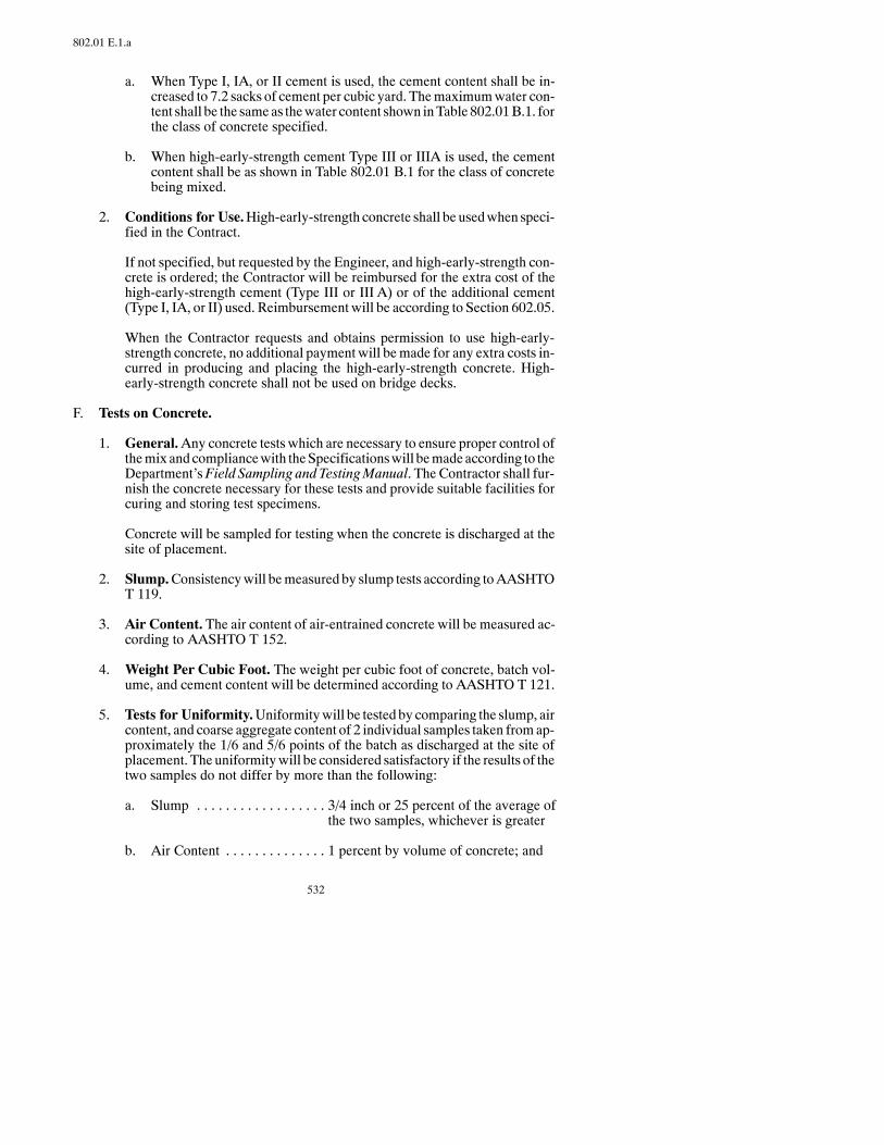
532
802.01 E.1.a
a. When Type I, IA, or II cement is used, the cement content shall be in-creased to 7.2 sacks of cement per cubic yard. Themaximumwater con-tent shall be the sameas thewater content shown inTable802.01B.1. forthe class of concrete specified.
b. When high-early-strength cement Type III or IIIA is used, the cementcontent shall be as shown in Table 802.01 B.1 for the class of concretebeing mixed.
2. Conditions for Use.High-early-strength concrete shall be usedwhen speci-fied in the Contract.
If not specified, but requested by the Engineer, and high-early-strength con-crete is ordered; the Contractor will be reimbursed for the extra cost of thehigh-early-strength cement (Type III or III A) or of the additional cement(Type I, IA, or II) used. Reimbursement will be according to Section 602.05.
When the Contractor requests and obtains permission to use high-early-strength concrete, no additional payment will bemade for any extra costs in-curred in producing and placing the high-early-strength concrete. High-early-strength concrete shall not be used on bridge decks.
F. Tests on Concrete.
1. General.Any concrete tests which are necessary to ensure proper control ofthemix and compliancewith theSpecificationswill bemadeaccording to theDepartment’sField Sampling and TestingManual. The Contractor shall fur-nish the concrete necessary for these tests and provide suitable facilities forcuring and storing test specimens.
Concrete will be sampled for testing when the concrete is discharged at thesite of placement.
2. Slump.Consistencywill bemeasured by slump tests according toAASHTOT 119.
3. Air Content. The air content of air-entrained concrete will be measured ac-cording to AASHTO T 152.
4. Weight Per Cubic Foot. The weight per cubic foot of concrete, batch vol-ume, and cement content will be determined according to AASHTO T 121.
5. Tests for Uniformity.Uniformitywill be tested by comparing the slump, aircontent, and coarse aggregate content of 2 individual samples taken fromap-proximately the 1/6 and 5/6 points of the batch as discharged at the site ofplacement. The uniformitywill be considered satisfactory if the results of thetwo samples do not differ by more than the following:
a. Slump 3/4 inch or 25 percent of the average of. . . . . . . . . . . . . . . . . .the two samples, whichever is greater
b. Air Content 1 percent by volume of concrete; and. . . . . . . . . . . . . .

533
802.04 A.1
c. Coarse Aggregate Content 6 percent by weight of the respective. . .(portion of each sample samplesretained when washedthrough a No. 4 sieve)
If the test results are not within the ranges specified above, the mixing time,batch size, or equipment methods used to proportion, mix, and transport theconcrete shall be changed to produce concrete meeting all specified require-ments.
6. Strength Tests. Concrete test specimens for compression and flexuralstrength tests will be made and cured according to AASHTOT 23. Concretecylinders will be tested for compressive strength according to AASHTO T22. Concrete beams will be tested for flexural strength according toAASHTO T 97.
802.02 MATERIALS.
A. General. Unless otherwise specified, Type I, IA, or II cement shall be used.
B. Materials shall meet the following:
Item SectionCement 804.01Air-Entraining Admixture 808.01Chemical Admixtures 808.02Curing Materials 810.01Water 812.01Fine Aggregate 816.01Coarse Aggregate 816.02Fly Ash 820.01
802.03 EQUIPMENT.
Equipment shall meet the following:
Item SectionGeneral 151.01Batching and Weighing Equipment 153.01Mixer 153.02Concrete-Transporting Equipment 153.03
802.04 CONSTRUCTION REQUIREMENTS.
A. Handling and Storing Materials.
1. Handling and Storing Cement or Fly Ash. Cement or fly ash of differenttypes, brands, or sources shall be handled and stored separately. Cement orfly ash shall not be inter-mixed during use or used alternately in any one unit.Storage that protects the cement or fly ash against dampness shall be pro-vided. Cementwhich contains caked lumps or is salvaged from spillage shallnot be used.
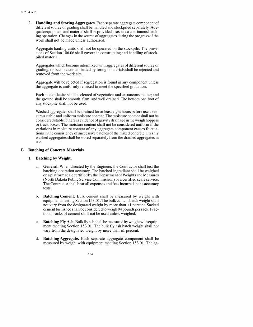
534
802.04 A.2
2. Handling and Storing Aggregates.Each separate aggregate component ofdifferent source or grading shall be handled and stockpiled separately. Ade-quate equipment andmaterial shall be provided to assure a continuous batch-ing operation. Changes in the source of aggregates during the progress of thework shall not be made unless authorized.
Aggregate hauling units shall not be operated on the stockpile. The provi-sions of Section 106.06 shall govern in constructing and handling of stock-piled material.
Aggregateswhich become intermixedwith aggregates of different source orgrading, or become contaminated by foreign materials shall be rejected andremoved from the work site.
Aggregate will be rejected if segregation is found in any component unlessthe aggregate is uniformly remixed to meet the specified gradation.
Each stockpile site shall be cleared of vegetation and extraneousmatter; andthe ground shall be smooth, firm, and well drained. The bottom one foot ofany stockpile shall not be used.
Washed aggregates shall be drained for at least eight hours before use to en-sure a stable and uniformmoisture content. Themoisture content shall not beconsidered stable if there is evidenceofgravitydrainage in theweighhoppersor truck boxes. The moisture content shall not be considered uniform if thevariations in moisture content of any aggregate component causes fluctua-tions in the consistency of successive batches of themixed concrete. Freshlywashed aggregates shall be stored separately from the drained aggregates inuse.
B. Batching of Concrete Materials.
1. Batching by Weight.
a. General.When directed by the Engineer, the Contractor shall test thebatching operation accuracy. The batched ingredient shall be weighedonaplatformscale certifiedby theDepartment ofWeights andMeasures(North Dakota Public Service Commission) or a certified scale service.The Contractor shall bear all expenses and fees incurred in the accuracytests.
b. Batching Cement. Bulk cement shall be measured by weight withequipmentmeeting Section 153.01. The bulk cement batchweight shallnot vary from the designated weight by more than ±1 percent. Sackedcement furnished shall be considered toweigh94poundsper sack. Frac-tional sacks of cement shall not be used unless weighed.
c. Batching Fly Ash.Bulk flyashshall bemeasuredbyweightwithequip-ment meeting Section 153.01. The bulk fly ash batch weight shall notvary from the designated weight by more than ±1 percent.
d. Batching Aggregate. Each separate aggregate component shall bemeasured by weight with equipment meeting Section 153.01. The ag-

535
802.04 D.2
gregate batch weight of each aggregate component shall not vary fromthe designated weight by more than ±2 percent.
e. Batching Water.Themixingwater for each batchmay bemeasured byvolume or by weight with equipment meeting Section 153.01 A. Thedesignated quantity ofmixingwater shall be added to each batch,withina tolerance of ±1 percent.
2. Batching by Volume. If a mobile mixer is used, it shall meet Section153.02 C.
C. Measuring and Dispensing Admixtures. Any admixtures used in the concreteshall be accuratelymeasured and dispensed using themanufacturer’s recommen-dations to give a uniformdistribution. Equipment andmethods formeasuring ad-mixtures, thequantityof admixtureused, and the time the admixture andwater areplaced in the batch shall be approvedby theEngineer. Thedispensing device shallrepetitivelycontrol thebatchingof theadmixturewithinanaccuracyof±5percentof the required volume of material or ±1 fluid ounce, whichever is greater. Dis-pensing equipment shall be arranged to permit convenient, visual observation ofthe volume of admixture dispensed or the admixture may be dispensed by otherapprovedmechanical ormanualmethods.Dispensingequipment shall beperiodi-cally checked and cleaned.
Wheremore than one admixture is used in the same batch, the admixtures shall beadded separately to prevent contact in their concentrated form.
The Contractor may be required to produce trial batches of the concrete mixwiththe admixture before use to determine if the water reduction, set retardation, aircontent, and strength of the concrete mixture meets requirements. The sameequipment, batch size, materials, etc., proposed for the work shall be used inpreparation of these trial batches. If all test requirements aremet, the trial batchesmay be incorporated into the work.
D. Mixing and Transporting Concrete.
1. General.The concretemay bemixed at the site of placement or by approvedready-mix methods. All concrete shall be mixed in approved, mechanicallyoperated mixers meeting Section 153.02.
The concrete shall be mixed in the quantity required to provide continuousplacementand finishingoperations.Additionofwater to retemper concrete isnot permitted.
Themixer shall be operated so successive batches of concrete do not becomemerged or intermixed during the mixing cycle.
All concrete shall be mixed until the cement, water, aggregates, and admix-tures are uniformly distributed. The concrete shall meet all requirements forslump, air content, and uniformity at the point of placement.
2. Mixing in Stationary Mixers.Stationarymixed concrete is concretemixedcompletely in a central mixing plant.
The batch volumemay exceed the rated capacity of the mixer by 10 percent,provided that concrete test data for strength and uniformity are satisfactoryand the batch can be mixed without spillage.

536
802.04 D.2
Themixing time shall bemeasured from the time all solidmaterials are in thedrumuntil discharge of that batchbegins. Thedrumshall be charged so apor-tion of the mixing water enters in advance of the aggregates and cement. Allremaining water shall be added after charging the aggregate and cement andbefore1/4of themixing timehas elapsed.Transfer time inmultiple-compart-ment mixers shall be included in mixing time. The mixing time per batchshall be aminimum of 60 seconds, except that: (1) when the concrete is usedin pavement, the Engineer may givewritten permission to reduce themixingtime to a minimum of 50 seconds if concrete test data for strength and uni-formity meet Specifications; and (2) if themixer is temporarily operated un-dermanual timingcontrol or hasa ratedcapacityof less than10cubic feet, theconcrete shall be mixed for a minimum of 90 seconds.
Concrete shall be delivered to the site of placement in an agitating truck, in atruck mixer operated at agitating speed, or in approved non-agitating equip-ment. The interval of timebetween introducing the cement to themixture andthe time the concrete has been completely discharged, shall not exceed 30minutes in non-agitating equipment and 60 minutes in agitating equipment.These time limits shall be reduced if weather conditions affect the concreteadversely.
3. Truck-Mixed Concrete. Truck-mixed concrete is concrete proportioned ata central plant and mixed and delivered to the site of placement in a truck-mixer (known as ready-mixed concrete).
Truck-mixed concrete shall not be produced until all equipment, facilities,and methods for handling and storing materials and for proportioning, mix-ing, and transporting the concrete have been approved. If the concrete is notdelivered to the site of placement at the times and rates necessary for continu-ous placement and finishing; or if the consistency, air content, or other prop-erties of the concrete do not conform to specified requirements the use oftruck mixed concrete shall be discontinued.
Equipment for transporting concrete shall meet Section 153.02 B. The vol-ume of concrete placed in the truck-mixer shall not exceed themaximumca-pacity shown on the manufacturer’s rating plate. The truck-mixer shall becleaned at periodic intervals to prevent accumulation of hardened concrete,and shall be emptied of all free water before receiving any batch ingredients.The interval between the time cement has been placed in contact with the ag-gregates or the water and the time the concrete has been completely dis-chargedshall not exceed60minutes.Themaximumdischarge time limitmaybe reduced if weather conditions affect the concrete adversely during thespecified time interval.
Mixing shall not be less than 70 revolutions nor more than 100 revolutionsafter all ingredients are charged in the truck-mixer. If the batch volume is 90percent or less than the rated mixing capacity, mixing may be reduced to aminimum of 50 revolutions. After mixing is completed, additional revolu-tions shall be at agitating speed. If water is added, the mixing drum shall berun an additional 30 revolutions at mixing speed after mixing has begun orbeen completed.Mixing and agitating speeds used shall follow themanufac-turer’s recommendations within the limits specified in Section 153.02 B.
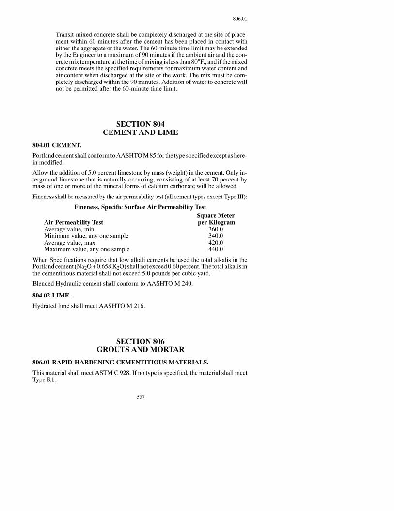
537
806.01
Transit-mixed concrete shall be completely discharged at the site of place-ment within 60 minutes after the cement has been placed in contact witheither the aggregate or the water. The 60-minute time limit may be extendedby the Engineer to a maximum of 90 minutes if the ambient air and the con-cretemix temperature at the timeofmixing is less than80°F., and if themixedconcrete meets the specified requirements for maximum water content andair content when discharged at the site of the work. The mix must be com-pletely discharged within the 90 minutes. Addition of water to concrete willnot be permitted after the 60-minute time limit.
SECTION 804CEMENT AND LIME
804.01 CEMENT.
Portlandcement shall conformtoAASHTOM85for the type specifiedexcept ashere-in modified:
Allow the addition of 5.0 percent limestone by mass (weight) in the cement. Only in-terground limestone that is naturally occurring, consisting of at least 70 percent bymass of one or more of the mineral forms of calcium carbonate will be allowed.
Fineness shall bemeasured by the air permeability test (all cement types except Type III):
Fineness, Specific Surface Air Permeability TestSquare Meter
Air Permeability Test per KilogramAverage value, min 360.0Minimum value, any one sample 340.0Average value, max 420.0Maximum value, any one sample 440.0
When Specifications require that low alkali cements be used the total alkalis in thePortlandcement (Na2O+0.658K2O) shall not exceed0.60percent. The total alkalis inthe cementitious material shall not exceed 5.0 pounds per cubic yard.
Blended Hydraulic cement shall conform to AASHTO M 240.
804.02 LIME.
Hydrated lime shall meet AASHTO M 216.
SECTION 806GROUTS AND MORTAR
806.01 RAPID-HARDENING CEMENTITIOUS MATERIALS.
This material shall meet ASTMC 928. If no type is specified, the material shall meetType R1.

538
806.02
806.02 EPOXY RESIN ADHESIVES.
This material shall meet AASHTO M 235 Type IV Grade III.
SECTION 808CONCRETE ADMIXTURES
808.01 AIR-ENTRAINING ADMIXTURES.
Air-entraining admixtures shall meet AASHTO M 154.
808.02 CHEMICAL ADMIXTURES.
Chemical Admixtures shall meet AASHTO M 194.
SECTION 810CONCRETE CURING MATERIALS
810.01 CURINGMATERIALS.
A. Burlap Cloth made from Jute or Kenaf.
Curing materials shall meet the following:
Burlap Cloth made from Jute or Kenaf AASHTO M 182. . . . . . . . . . . . . . .
B. Liquid-Membrane-Forming Compounds, White Pigmented, Type 2
Curing materials shall meet the following:
Liquid-Membrane-Forming Compounds,White Pigmented, Type 2 AASHTO M 148. . . . . . . . . . . . . . . . . . . . . . .
C. Liquid-Membrane-FormingCompounds,WhitePigmented,Type2,ClassB
The resin used in the curing compound shall be 100 percent poly-alphamethylstyrene and conform to all requirements in the following:
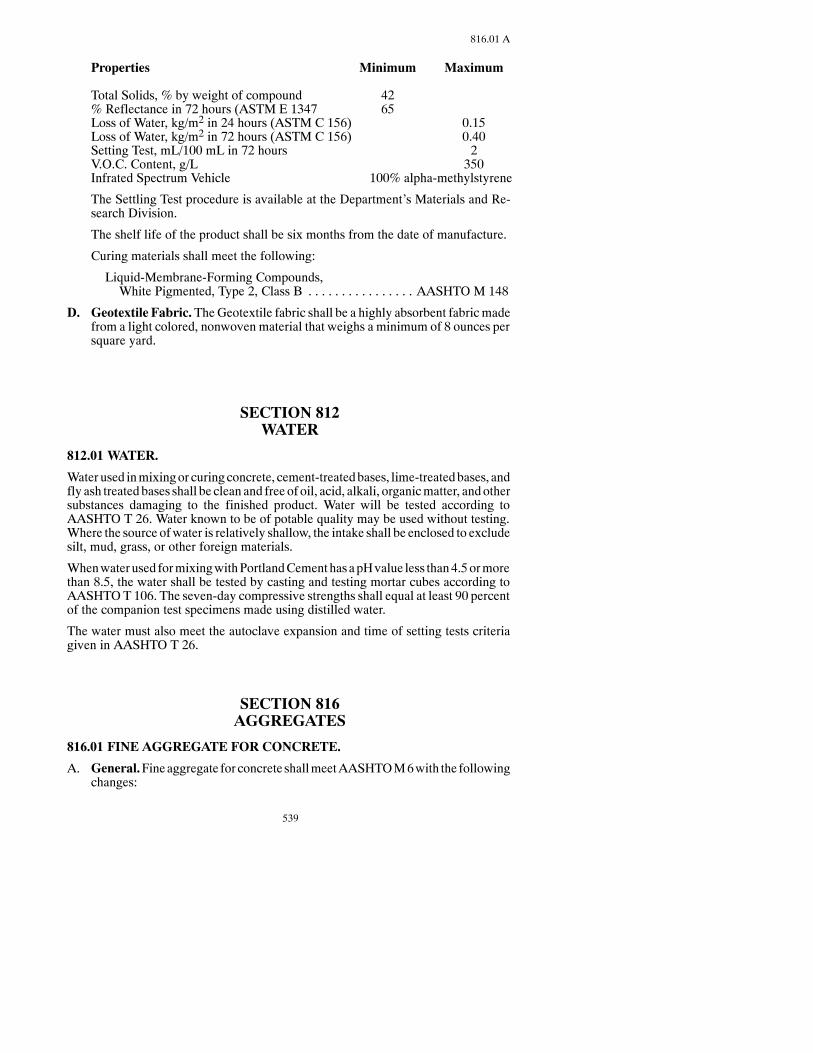
539
816.01 A
Properties Minimum Maximum
Total Solids, % by weight of compound 42% Reflectance in 72 hours (ASTM E 1347 65Loss of Water, kg/m2 in 24 hours (ASTM C 156) 0.15Loss of Water, kg/m2 in 72 hours (ASTM C 156) 0.40Setting Test, mL/100 mL in 72 hours 2V.O.C. Content, g/L 350Infrated Spectrum Vehicle 100% alpha-methylstyrene
The Settling Test procedure is available at the Department’s Materials and Re-search Division.
The shelf life of the product shall be six months from the date of manufacture.
Curing materials shall meet the following:
Liquid-Membrane-Forming Compounds,White Pigmented, Type 2, Class B AASHTO M 148. . . . . . . . . . . . . . . .
D. Geotextile Fabric.TheGeotextile fabric shall be a highly absorbent fabricmadefrom a light colored, nonwoven material that weighs a minimum of 8 ounces persquare yard.
SECTION 812WATER
812.01 WATER.
Water used inmixingor curingconcrete, cement-treatedbases, lime-treatedbases, andfly ash treated bases shall be clean and free of oil, acid, alkali, organicmatter, andothersubstances damaging to the finished product. Water will be tested according toAASHTO T 26. Water known to be of potable quality may be used without testing.Where the source ofwater is relatively shallow, the intake shall be enclosed to excludesilt, mud, grass, or other foreign materials.
Whenwater used formixingwithPortlandCementhasapHvalue less than4.5ormorethan 8.5, the water shall be tested by casting and testing mortar cubes according toAASHTOT 106. The seven-day compressive strengths shall equal at least 90 percentof the companion test specimens made using distilled water.
The water must also meet the autoclave expansion and time of setting tests criteriagiven in AASHTO T 26.
SECTION 816AGGREGATES
816.01 FINE AGGREGATE FOR CONCRETE.
A. General.Fineaggregate for concrete shallmeetAASHTOM6with the followingchanges:
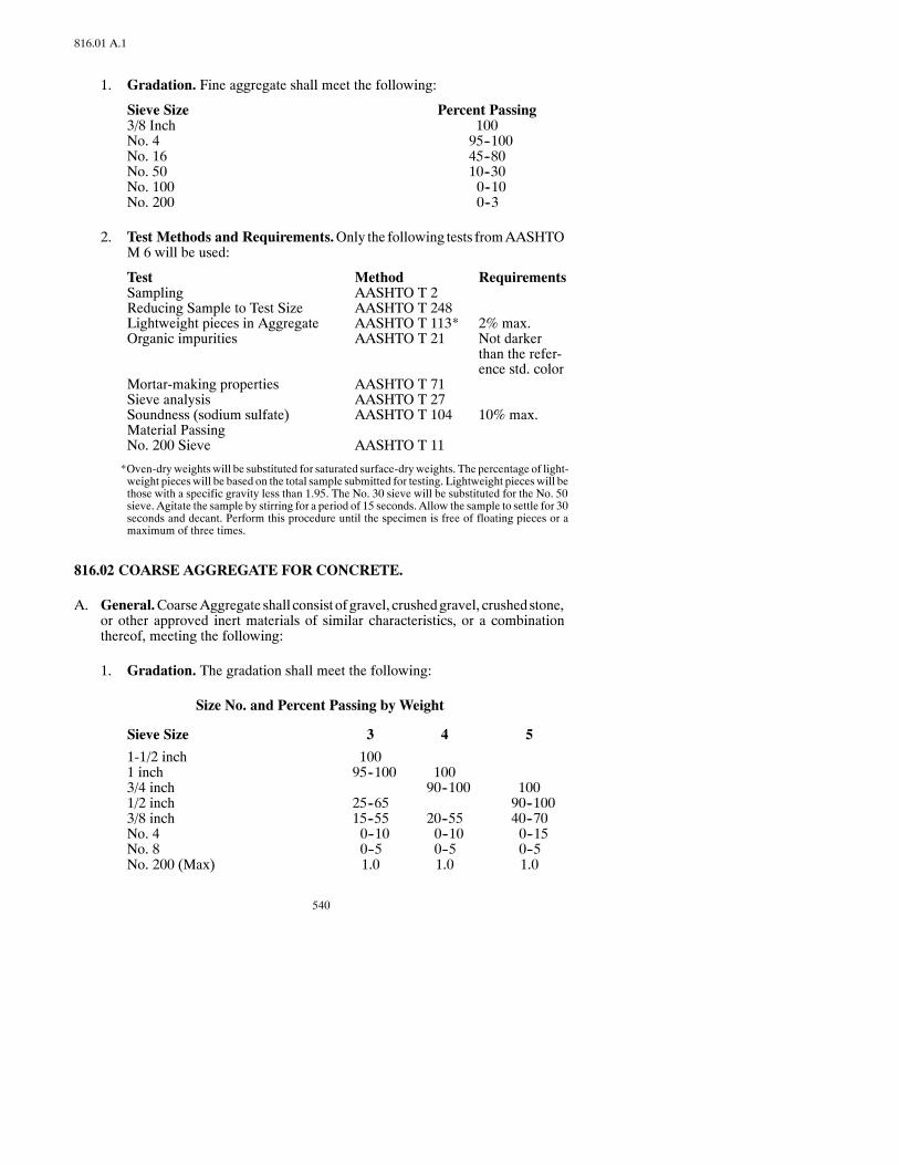
540
816.01 A.1
1. Gradation. Fine aggregate shall meet the following:
Sieve Size Percent Passing3/8 Inch 100No. 4 95--100No. 16 45--80No. 50 10--30No. 100 0--10No. 200 0--3
2. Test Methods and Requirements.Only the following tests fromAASHTOM 6 will be used:
Test Method RequirementsSampling AASHTO T 2Reducing Sample to Test Size AASHTO T 248Lightweight pieces in Aggregate AASHTO T 113* 2% max.Organic impurities AASHTO T 21 Not darker
than the refer-ence std. color
Mortar-making properties AASHTO T 71Sieve analysis AASHTO T 27Soundness (sodium sulfate) AASHTO T 104 10% max.Material PassingNo. 200 Sieve AASHTO T 11
*Oven-dry weights will be substituted for saturated surface-dryweights. The percentage of light-weight pieces will be based on the total sample submitted for testing. Lightweight pieces will bethose with a specific gravity less than 1.95. The No. 30 sieve will be substituted for the No. 50sieve. Agitate the sample by stirring for a period of 15 seconds. Allow the sample to settle for 30seconds and decant. Perform this procedure until the specimen is free of floating pieces or amaximum of three times.
816.02 COARSE AGGREGATE FOR CONCRETE.
A. General.CoarseAggregate shall consist of gravel, crushedgravel, crushedstone,or other approved inert materials of similar characteristics, or a combinationthereof, meeting the following:
1. Gradation. The gradation shall meet the following:
Size No. and Percent Passing by Weight
Sieve Size 3 4 5
1-1/2 inch 1001 inch 95--100 1003/4 inch 90--100 1001/2 inch 25--65 90--1003/8 inch 15--55 20--55 40--70No. 4 0--10 0--10 0--15No. 8 0--5 0--5 0--5No. 200 (Max) 1.0 1.0 1.0

541
816.02 A.2
2. Test Methods and Requirements.RequirementsMax. Percent byWeight of the PlusNo. 4 FractionTest Method
a. Shale NDDOT Method** 0.7
b. Iron OxideParticles NDDOT Method** 4.0*
c. Lignite and OtherCoal NDDOT Method** 0.5
d. Soft ParticlesExclusive of a, b, c(Includes clay,and other friablematerial) NDDOT Method** 2.5
e. Thin or ElongatedPieces (maximumthickness less than1/4 the maximumwidth, or maximumlength more thanthree times themaximum width) NDDOT Method** 15.0
f. Material PassingNo. 200 Sieve AASHTO T 11
g. L.A. Abrasion AASHTO T 96 40.0
h. Soundness (SodiumSulfate) AASHTO T 104 12
i. Sampling AASHTO T 2
j. Reducing Sampleto Test Size AASHTO T 248
k. Sieve Analysis AASHTO T 27
*NOTE: For spall repairs for concrete pavements and for bridge deck overlays, the maximumiron oxide particles shall be 2.0 percent.
**Field Sampling and Testing Manual
Coarse aggregate for use in concrete that is subjected to moisture, extendedexposure to humid atmosphere, or contact with moist ground shall not con-tain any materials that are deleteriously reactive with the alkalies in thecement in a quantity sufficient to cause excessive expansion of mortar or

542
816.02 A.2
concrete. If such materials are present in injurious quantities, the coarseaggregatemaybeusedwith acement containing less than0.6percent alkaliescalculated as sodium oxide or with the addition of a material that has beenshowntopreventharmful expansiondue to thealkali-aggregate reaction.Thereactivity shall be determined according to the test methods specified inAASHTO M 80.
816.03 AGGREGATES FOR SURFACING, BASE, ASPHALT MIXES,BLOTTER, AND SEAL COATS.
A. General. The material shall consist of sound, durable particles of gravel or sandwhich may include limited quantities of fine soil particles as binding material. Itshall be free of sod, roots, and other organic matter. The physical characteristicsand quality of the materials shall be approved by the Engineer.

543
816.03 B
3” 1-1/2”
1-1/4”
1” 3/4”
5/8”
1/2”
3/8”
No.4
No.8
No.10
No.16
No.30
No.50
No.100
No.200
Shale1
L.A
.Abrasion1
PlasticityIndex2
FracturedFaces3
SieveSize
Percent
Passing
3 100
80--100
35--85
20--50
0--15
12%
Aggr.
for
Subgrade
Repair5
2 100
50--95
0--15
0--4
Permeable
Trench
Backfill
4 100
35--85
10--50
7--17
15%
50%
10%
Shldr.
Aggr.
Surface
3M 100
80--100
35--85
20--50
4--10
12%
Aggr.
for
Blended
Base
5 100
90--100
35--70
16--40
4--10
12%
50%
10%
Aggr.
Base5
7 100
95--100
85--100
60--90
15--25
2--10
0--3 8% 40%
85%
Permeable
Base
Aggr.
8 100
35--80
20%
13 100
70--100
38--75
22--62
12--45
7--15
12%
50%
10%
Tem
p.Traffic
Surface
Aggr.
Aggr.
Surface
CLASS
OFAGGREGATEANDSPECIFICATIONLIM
ITS
TableI:AggregatesforSubgrade
Repair,TrenchBackfill,Bases,and
Surfacing
FootnotesforTablesIandII:
1Maximum
AllowablePercentages.
2Maximum
allowableunlessrangeshow
n.N.P.=
Non
Plastic
asperAASHTOT-90.U
sematerialpassing
theNo.40
sieve(standardmethod).ForClass5aggregatethemaximum
allowablePlasticity
Indexshallbe
determinedfrom
thefollowingformula:Max.allowablePIforClass5=10
-(%
PassingNo.40
Sieve/10)
3Minimum
weightpercentageallowablefortheportionoftheaggregateretainedon
aNo.4sievehaving
atleast1
fracturedfaceforClasses4,5,13,27,29,31,and33,and
atleast2
fracturedfacesforClass7.
4Minimum
percentageofmaterialpassing
aNo.4sievethatiscomposedoffracturedmaterialproducedby
acrushing
process.TheContractorshalldem
onstratethatthecrushing
operationproducesthisresult.
5SalvagedBasemeetingtherequirem
entsofSection302and817maybesubstitutedforCl.3orCl.5virginaggregate,unlessotherwisespecifiedon
thePlans.
B.SpecificRequirements.

544
816.03 B
3” 1-1/2”
1-1/4”
1” 3/4”
5/8”
1/2”
3/8”
No.4
No.8
No.16
No.30
No.50
No.200
Shale1
L.A
.Abrasion1
Plasticity
Index2
FracturedFaces3
CrushedFines4
27 100
70--100
40--70
15--35
2.0--7.0
5.0%
40% 3
55%
10%
SieveSize
Percent
Passing
29 100
70--100
40--70
15--35
2.0--7.0
5.0%
40% 3
65%
40%
31 100
70--100
40--70
15--35
2.0--7.0
5.0%
40%
N.P.
75%
60%
33 100
70--100
40--70
15--35
2.0--7.0
5.0%
40%
N.P.
95%
80%
42 100
20--70
2--20
0--5
8.0%
40%
Chip
Seal
Sand
Seal45 100
85--100
45--80
10--30
0--3
3.0%
43 100
20--70
0--17
0--2
8.0%
40%
44 100
90--100
0--20
Chip
Seal
Blotter
Sand
AsphaltHotMixLow
toHighQuality
TableII:A
ggregatesforAsphaltMixes,Blotter,and
SealCoats
FootnotesforTablesIandII:
1Maximum
AllowablePercentages.
2Maximum
allowableunlessrangeshow
n.N.P.=
Non
Plastic
asperAASHTOT-90.U
sematerialpassing
theNo.40
sieve(standardmethod).ForClass5aggregatethemaximum
allowablePlasticity
Indexshallbe
determinedfrom
thefollowingformula:Max.allowablePIforClass5=10
-(%
PassingNo.40
Sieve/10)
3Minimum
weightpercentageallowablefortheportionoftheaggregateretainedon
aNo.4sievehaving
atleast1
fracturedfaceforClasses4,5,13,27,29,31,and33,and
atleast2
fracturedfacesforClass7.
4Minimum
percentageofmaterialpassing
aNo.4sievethatiscomposedoffracturedmaterialproducedby
acrushing
process.TheContractorshalldem
onstratethatthecrushing
operationproducesthisresult.
5SalvagedBasemeetingtherequirem
entsofSection302and817maybesubstitutedforCl.3orCl.5virginaggregate,unlessotherwisespecifiedon
thePlans.
41 100
20--70
0--17
0--1.5
8.0%
40%
Chip
Seal

545
816.03 C
C. Sampling and Testing.
Sampling AASHTO T 2Reducing Sample to Test Size AASHTO T 248Liquid Limit AASHTO T 89Plastic Limit and Plasticity Index AASHTO T 90Los Angeles Abrasion AASHTO T 96Lightweight Pieces of Aggregate AASHTO T 113*Sieve Analysis AASHTO T 27Amount of Material Finer than AASHTO T 11**No. 200 Sieve in Aggregate
Fractured Faces Department Method
*Oven-dry weights will be substituted for saturated surface-dry weights. The No. 30 sieve will besubstituted for theNo. 50 sieve. The percentage of lightweight pieceswill be based on the total sam-ple retained on the No. 30 sieve. Lightweight pieces will be those with a specific gravity less than1.95. Agitate the sample by stirring for a period of 15 seconds. Allow the sample to settle for 30seconds and decant. Perform this procedure until the specimen is free of floating pieces or a maxi-mum of three times.
**AASHTO T 11 is to be used in conjunction with AASHTO T 27 for all aggregate tests.
SECTION 817SALVAGED BASE COURSE
817.01 GENERAL REQUIREMENTS.
Salvaged Base may be composed of the followingmaterials: processed virgin aggre-gate, existing aggregate base, existing bituminous material, stockpiled bituminousmaterial, existing concrete material, and/or stockpiled concrete material. All removalmaterial shall be incorporated into the Salvaged Base as detailed in the plans unlessotherwise approved in accordance with section 817.02 E. One-hundred percent pro-cessed virgin aggregate as specified in section 817.02 Dmay be supplied to make-upanydifferencebetween theSalvagedBasequantityproducible fromthe removalquan-tities and the requiredSalvagedBase quantity. Additionally, any removal quantities inexcess of that required for Salvaged Base production shall become the Contractor’sproperty.
The “Basis of Estimate” contained in the Plans indicates the approximate removalquantities, the quantity of aggregate necessary to supplement the salvaged material,and the approximate blend percentages to be used to produce the Salvaged BaseCourse. Depending on the Contractor’s operations, the Salvaged material quantitiesshown in theBasis of Estimatemayormaynot be availablewhen theContractor needsto incorporate themback into theproject asSalvagedBase.TheContractor is responsi-ble for supplying thematerial required tomake up anySalvagedBase short fall causedby project phasing. Any make up material supplied by the Contractor shall meet therequirements of Section 817.02A. All costs for supplying thismake-upmaterial shall

546
817.01
be paid for as “Salvage Base.” Anymaterial not available due to project phasing shallultimately be incorporated into theSalvagedBaseunless otherwise approved in accor-dance with section 817.02 E.
Materials composing the final combinedSalvagedBase shall be combinedwith a con-veyor, pugmill, bins or othermechanical device. Combining/blending on the roadwayshall not be permitted.
TheContractormay elect tomine the existingpavement in place prior to removal fromthe roadway. If this method is used, the Contractor shall take measurements to ensurethe proper depth is being mined. During the mining operation, the Contractor shallphysicallydigdown, approximatelyevery500feet (eachpass), tomeasure theexistingpavement and base depth. The results of the measurements shall be made available tothe Engineer daily.
TheSalvagedBase shall be free of reinforcing steel, soil, scoria, andother foreignma-terials.
817.02 MATERIALS.
A. General.All final combinedmaterials (i.e. SalvagedBase) shallmeet the follow-ing requirements:
Percent PassingSieve Size General Salvaged Base under
Permeable Base1-1/2 in. 100 1001 in. 90 -- 100 90 -- 100No. 4 35 -- 85 N/ANo. 30 16 -- 50 N/ANo. 200 0.0 -- 12.0 N/A
The continuous-reinforced concrete pavement (CRCP), jointed concrete pave-ment (doweled or non-doweled), median paving, sidewalks, curb and gutter,driveways, parking lots, ditch liners, existing aggregate base and bituminouspavement shown in the plans for removal shall be incorporated into the salvagedbase material. In addition to the aforementioned items, any other removed con-crete or bituminous materials may (at the Contractor’s option) be incorporatedinto the salvaged base.
The gradation “Salvaged Base under Permeable Base” will only be allowed forPCC salvaged material. The salvaged material must be verified as PCC recycleand free of deleteriousmaterials to the satisfaction of the Engineer prior to use onthe project.
B. Contractor Supplied Salvaged Material. The Contractor may substitutecontractor-supplied salvaged material (i.e. stockpiled material) for the removedmaterial, as longas the removedmaterial is notwasted and theuseof the substitutematerial is acceptable and approved by the Engineer.
C. ProcessedVirginAggregate forBlend. Virgin aggregate used for blendingwiththe salvage material shall be; composed of non-organic granular material, have amaximum shale content of 12 percent, and have a plasticity index of 0 -- 6.
547
817.02 G.1
D. Processed Virgin Aggregate In Lieu of Salvaged Base. Any virgin aggregateused in lieu of Salvaged Base shall meet the requirements for Class 5 AggregateBase as detailed in Section 816.
E. Use of Removed Materials. The Contractor may request not to incorporate re-movedmaterial into the Salvaged Base if it is determined that such incorporationis impractical and not in the publics best interest. The request shall be in writing,include a detailed justification as to why the use of the removed material is im-practical, and is subject to the approval of the Engineer. Removal items not incor-porated into the project shall become the property of the Contractor and disposedof in accordance with Section 107.10.
F. Bituminous Combined Material.
1. If theContractor intends to use a stockpile containing bituminousmaterial asthe final combined Salvaged Base, he shall, under supervision of the Engi-neer, supply theEngineerwith three (3) randomsamples, prior to placing anyof the material on the project. These samples shall be taken in accordancewith AASHTO T 2 and be at the Contractor’s expense. At the Owner’s ex-pense, the samples will be tested, by extraction (AASHTO T 164), for bitu-men content and the results averaged. Stockpiled material with an initial av-erage extraction of greater than 3.5 percent will not be allowed as the finalSalvaged Base. Additionally, if any one sample has an extraction of greaterthan 4.0 percent, the material shall not be allowed for use as the final Sal-vaged Base. However, the Contractor may elect to blend the material withothermaterials tomeet the requirements of Section817.Additionally, as spe-cified inSection302.02B, routine extraction testingwill beperformed,whenstockpiled material is supplied. In all cases, the final combined SalvagedBase shall meet all other requirements of Section 817.
2. The Contractor may, at his option, combine stockpiled material containingbitumenwithaggregateor salvagedconcrete at a ratenot toexceed50percentstockpile with 50 percent (or more) aggregate or salvaged concrete byweight, without the required extraction sampling and testing (either initial orroutine as specified in Section 302.02 B). The combining of this materialshall be done off of the road usingmechanical equipment, as required above.The combined material shall not be stockpiled at the original stockpile siteprior to delivery to the project (stockpiling in the project staging area will beallowed, as long as the staging area is not at the original stockpile site). Addi-tionally, the final combined Salvaged Base shall meet all other requirementsof Section 817.
3. If existing bituminous material from the project is incorporated into the Sal-vaged Base, the bituminous material shall be incorporated at a rate less thanor equal to 50 percent bituminous to 50 percent (or more) aggregate or re-cycled concrete, byweight.Noextraction testingwill be required for thisma-terial.
G. Concrete Combined Material.
1. Salvaged concrete (either stockpiled or existingmaterial)may constitute anyportion, up to and including 100 percent, of the final combined material.However, the final combined Salvaged Base shall meet all other require-ments of Section 817.
548
817.02 G.2
2. Salvaged concrete shall be free of reinforcing steel, bitumen, soil and otherforeignmaterials. If bitumen is present in the salvagedmaterial, thematerialshall become subject to the requirements of Section 817.02 B, above. If steelis present inmaterial tobeusedasSalvagedBase, theContractormayuse anymethodacceptable to theEngineer to remove the steel,whichwill become thepropertyof theContractor. If theContractor chooses towaste the steel, it shallbe disposed of according to Section 107.10.
SECTION 818BITUMINOUS MATERIALS
818.01 GENERAL REQUIREMENTS.
The original certificate of compliance covering material shipped in each car or tanktruck shall be furnishedat the timeof shipment.The certificate shall be furnished to theapplicable Department’s district office and shall contain the following information:
1. Project Number.
2. Destination.
3. Quantity Contained in Car or Tank Truck.
4. Gross, Tare, and Net Weights if Shipped by Truck.
5. Car Initials and Number or Tank Truck Number.
6. Type and Grade of Bitumen.
7. Date of Shipment.
8. Specific Gravity.
9. Statement that the material meets all of the Specifications.
818.02 SPECIFIC REQUIREMENTS.
A. Asphalt Cement
1. Penetration Graded Asphalt Cement AASHTO M 20. . . . . . . . .
2. Viscosity Graded Asphalt Cement AASHTOM 226 Table 2. . . . . . . . . . .
3. Performance Graded (PG) Asphalt Cement AASHTO M 320*. . . .
*Testing Tolerances will be allowed according to Table 1 of the Department’s Procedure for Acceptance ofPerformanceGraded BituminousMaterial. Acceptance of PG asphalt shall be according to the CombinedState Binder Test Group procedures.

549
818.02 E
B. Rapid-Curing Cutback Asphalt AASHTO M 81. . . . . . . . . . . . . . .
C. Medium-Curing Cutback Asphalt AASHTO M 82. . . . . . . . . . . . .
MC3000P shall meet the following requirements:
AASHTO MC3000PKinnematic Viscosity @ 140°F. T 201 3000--7000Flash Point, F (TOC) T 79 150 min.Water, % T 55 0.2 max.
Distillation Test: Distillate % Volumeto 437°F. --to 500°F. 0--15%to 600°F. 15--75%% Residue to 680°F. T 78 80 min.
Tests on Residue from DistillationPenetration @ 77°F. T 49* 250 max.Ductility @ 77°F. T 51 100 min.Absolute Vix @ 140°F T 202* 300--1200
Tests on Polymerized Base AsphaltDuctility @ 77°F. T 51 100 min.Ductility @ 39°F. (5 cm/min, cm) T 51 50 min.Toughness, inch--pounds ASTM D 5801 75 min.Tenacity, inch--pounds ASTM D 5801 50 min.% Polymer 2% solids min.
***Penetration or Viscosity is specified but in no case will both be required.
D. Cationic Emulsified Asphalt.
1. Cationic Emulsified Asphalt shall meet the requirements of AASHTO M208 with the following exceptions:
a. Grade CMS-2 shall have 5 percent to 15 percent oil distillate by volumeof emulsion.
b. Grade CMS-2h and CSS-1h, the maximum penetration permitted at77°F. (25°C) 100 gm, 5 sec., in the “Test on Residue from DistillationTest,” shall be raised to 120.
c. Footnote “b” ofAASHTOM208will not apply to either the storage sta-bility or the sieve test requirements.
2. Modified Cationic Emulsified Asphalt. Emulsified asphalt grades shallmeet the requirements of AASHTO M 316.
E. Anionic Emulsified Asphalt AASHTO M 140. . . . . . . . . . . . . . . . . .
WhenusingSS-1h, themaximumpenetrationpermittedat 77°F(25 °C)100gm,5sec, in the “Test on Residue from Distillation”, shall be raised to 120.

550
818.02 E
HFRS 2P emulsified asphalt shall be an emulsified blend of polymerized asphalt,water, and emulsifiers. The asphalt cement shall be polymerizedprior to emulsifi-cation and shall contain a minimum of 3 percent polymer by weight of asphaltcement. The emulsion shall be pumpable and suitable for application through adistributor.
Tests on Emulsions Min MaxViscosity, Saybolt Furol @ 122°F. 50 400Storage Stability* PassesCure Test** PassesSieve (%) 0.1Demulsibility 50ml 0.10 N CaCl2, %*** 40Oil Distillate by Volume of Emulsion, %**** 3.0Residue by Distillation, % 65
Tests on Residue from Distillation TestsPenetration @ 77°F. (25°C.) 100 200Ductility @ 39°F. (4°C.) 5 cm/min. cm 30Softening Point (R & B) Degrees F 100Elastic Recovery @ 50°F. (10°C.) 55Float Test @ 140°F. (60°C.) sec 1200
****Storage Stability: In addition to requirement ofAASHTOT59, on examination of thetest cylinder after the emulsion has been standing undisturbed for 24 hours, the sur-face shall show no white, milky covered substance but shall be a homogenous browncolor throughout.
****The cure test is performed as follows: Pour approximately 1 gram of (HFMS-2P orHFRS-2P) emulsion onto a metal surface (lid of a 3 oz. Ointment tin). Allow the testsample to cure at temperatures of at least 80°F under a heat light for four hours. Theoutdoor sunlight may be used as a testing site. After the four-hour curing period, the(HFMS-2P or HFRS-2P) emulsion shall show no tackiness or tendency to stick to thefingers when pressed.
****This test not a requirement on representative samples is waived if successful applica-tion of the material has been achieved in the field.
****The distillation test for CRS-2P emulsion shall be in accordance with AASHTO T 59,8--12 except that the distillation temperature shall bewhat the emulsionmanufacturerrecommends.
Property ASTM Test HFMS-2 HFRS 2P HFRS-2Viscosity, Sabolt Furol @ 122°F.(50°C) Note #1 35-150 50-200 50-200
Sieve Test, Retained on #20, max. % Note #1 0.1 0.1 0.1Storage Stability, 24 hour, max. % Note #1 1.0 1.0 1.0Asphalt Residue by Distillation,min. % Note #2 62 65 63
Oil Portion of Distillate by volume,max. % D 244 3.0 3.0 3.0
Float Test @ 140°F., Seconds, min. Note #3 1200 1200 1200Solubility in Trichlorethylene,min. % D 4 97.5 97.5 97.5
Penetration, 77°F., 100 gm, 5 sec. D 5 140--225 140-225 140-225Apparent Viscosity @ 140°F. D 4957 Note #4 Note #4

551
818.02 E
Demulsibility, 0.02 N CaCl2, min. % D 244 40 40Demulsibility, 0.1 N CaCl2, min. % 30Ductility, 77°F., 5 cm/min., cm, min. AASHTO T 51 40 40Elastic Recovery, 77°F., min. % Note #5 58
Note #1.ASTMMethodD 244 shall be used for the Storage Stability, Sieve Test,and the Saybolt Furol Viscosity Test. The test results shall be reported, but the re-quirements may be waived if successful application of the material has beenachieved in the field.
Note #2. AASHTO T 59 will be used except when testing the HFRS 2P the testshall bemodified to include a 400+ 10°F.maximum temperature to be held for 15minutes.
Note #3. ASTM Method D 139 shall be used to test the float. When testingHFMS-2, the residue from distillation shall be poured immediately into the floatcollar at 500°F. When testing HFRS-2P, the residue from distillation shall bepoured into the float collar at 400°F. If the residuehasbeenallowed to cool, it shallbe reheated and poured into the collar.
Note #4.Viscosity-Penetration results shall fall within the designated area on thefollowing chart at a shear rate of 1.0 sec--1. The viscositywill be determined usingaModified Koppers size 100 viscometer tube at 140°F. and 300mmHg vacuum.
Note #5. AASHTO T 51 with the following modifications:
-- Prepare and test one specimen.
-- After filling themoldwith the hot sample, cool to room temperature for a pe-riod of 30--40 minutes, then place the base plate and filled mold in the waterbath maintained at 50°F. for 85--95 minutes before trimming.
-- Remove the specimen from the bath and immediately position it in the duc-tilometer, which has a bath temperaturemaintained at 50°F. Proceed to elon-gate the specimen at the rate of 5 cm/min.
-- Elongate the specimen to 20 cm, then stop the ductilometer. Immediately cutthe elongated specimen approximately in half with a scissors.
-- Allow the specimen to remain in the ductilometer undisturbed for 1 hour.
-- Retract the movable half of the specimen until the two broken ends touch,then observe the elongated measurements.
-- Calculate: % Elastic Recovery = 20 -- X × 10020
X = Elongated measurement after rejoining the ends of the specimen.
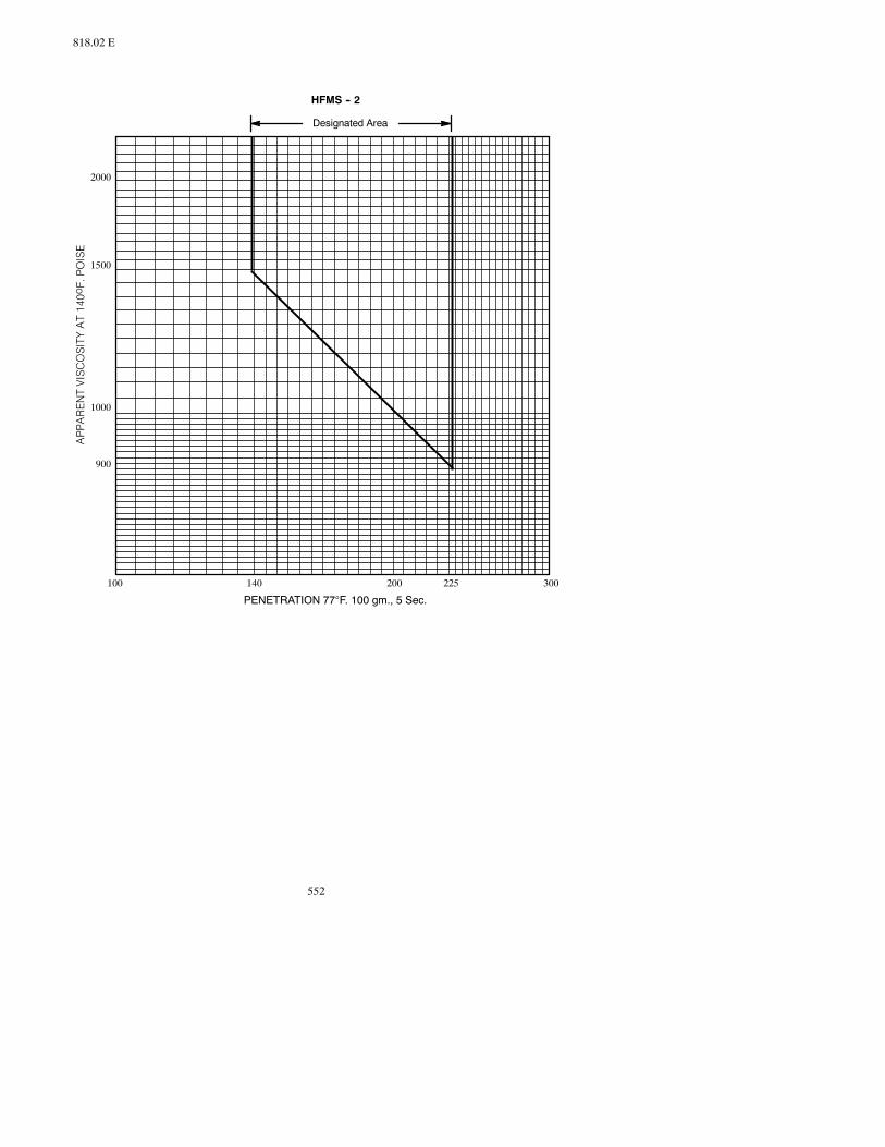
552
818.02 E
900
1000
1500
2000
140100 200 225 300
Designated Area
HFMS -- 2
PENETRATION 77°F. 100 gm., 5 Sec.

553
820.01 B
F. Recycling Agent.
The recycling agent shall meet the following:
TestProperties Method RequirementsViscosity, 140°F., cSt ASTM D 445 200-800Flash Point, °F., C.O.C. AASHTO T 48 425, MinimumSolubility in Trichloroethylene,min. % ASTM D 4 99.0
Saturates, max. % 30Thin Film Oven Test AASHTO T 179Loss of Heating, % 4.0%, max.Viscosity, 140°F., cSt Maximum of 3
time the orig.viscosity
G. Slow-Curing Cutback Asphalt. Slow-curing cutback asphalt shall meetASTM D2026, except that theminimumFlashPoint for theSC800will be240°F.
SECTION 820FLY ASH
820.01 GENERAL.
Fly ash shall meet the following for the specific type of work:
Type of Work SpecificationPortland Cement Concrete AASHTO M 295Lime Fly Ash Treated Subgrade ASTM C 593Econocrete AASHTO M 295Aggregate Base ASTM C 593
Sampling and testing all fly ash shall be at the Contractor’s expense, except as de-scribed below.
Thechemical compositionof fly ash required tomeetAASHTOM295shallbeClassF(as described in Table 1 of AASHTO M 295) with the following modifications:
A. The total of silicone dioxide (SiO2) plus aluminumoxide (Al2O3) plus iron oxide(Fe2O3) shall be at least 66.0 percent by dry weight of the total fly ash composi-tion.
B. The silicon dioxide (SiO2) shall be at least 40.0 percent by dry weight of the totalfly ash composition.

554
820.01 C
C. Loss on Ignition shall be no more than 2.0 percent maximum.
D. The optional requirements of Table 2 shall be required.
In addition to the certificate described below, the Contractor shall supply fly ash testdata to theEngineer in the formof a chemical andphysical analysis report, preparedbyan independent lab, prior to the Department proceedingwith the concrete mix design.The Department may retest project samples to verify Specification compliance. TheDepartment will select an independent lab to perform verification testing and will beresponsible for cost of the testing. When performed, the verification tests will be thebasis of acceptance.
Fly ash shall be from an electrical generating plant using a single coal source. Fly ashproducedat plantswhere the limestone injectionprocess isused for controlling air pol-lutants will be considered unacceptable for use in Portland Cement Concrete. TheContractor shall provide weather-tight storage facilities for the fly ash either at thesource or on the Project site.
Fly ash delivered to theDepartment and the Project shall be accompanied by aCertifi-cate of Compliance based on a testing program which ensures a satisfactory and uni-form product relative to these Specification requirements. The Certificate of Compli-ance coveringmaterial shipped in each car or tank truck shall be furnished in triplicateat the time of shipment. The original is to be furnished to the Materials and ResearchEngineer, Department of Transportation, 300 Airport Road, Bismarck, North Dakota58504, with one copy going to the consignee and one copy to the Engineer.
The certificate shall contain the following information:
A. Project number and name of Contractor.
B. Fly ash source by name of company and location of plant.
C. Quantity contained in tank truck or railroad car.
D. Gross, tare, and net weight if shipped by truck.
E. Car initials and number or tank truck number.
F. Date of shipment.
G. Statement that the material meets all Specification requirements.
H. Signature of the person having legal authority to bind the supplier.
SECTION 822PENETRATINGWATER REPELLENT
822.01 GENERAL.
The penetrating water repellent treatment solution shall consist of an Organo Siliconcompounddissolved in a suitable solvent carrier that,when applied, produces ahydro-phobic surface covalently bonded to the concrete.

555
824.01
The Organo Silicon compound shall be one of the following:
ALKYL-ALKOXYSILANEOLIGOMEROUS ALKYL-ALKOXYSILOXANE
The solvent will leave less than 1 percent residue upon evaporation.
The solution shall contain aminimumof 40 percent solids. Thematerial shall be certi-fied tomeet or exceed the performance criteria listed below based on a single applica-tion of the solution according to the manufacturer’s recommended rate of coverage.
The penetration water repellent treatment solution shall not stain, discolor, or darkenconcrete. Application of the solution shall not alter the surface texture or form a coat-ing on concrete surfaces and shall be compatible with the use of special surface finishtexture coatings as specified. Treated concrete shall be surface dry within 30 minutesafter application.
822.02 TESTING.
The treated concrete shall meet the following requirements:
A. Absorption.
Test Duration Max. Absorption MethodWater Immersion 48 hrs. 1% by weight ASTM C 642
50 days 2% by weight ASTM C 642
B. Chloride Ion Penetration.
Test Duration Max. Absorption Cl- MethodSalt Water Ponding* 90 days 0.75 lb. per cu. yd. AASHTO T 259
Depth: 1/2 inch AASHTO T 260to 1 inch
*Based on non-abraded specimens.
C. Treatment Penetration.
Test Minimum Depth MethodPenetration 0.15 inch DOT Procedure*
*Refer to the Department’s Field Sampling and Testing Manual.
D. Vapor Permeability.
Treated concrete shall retain itsmoisture vapor permeability as determined by theDepartment’s test procedure.
SECTION 824DAMPPROOFING ANDWATERPROOFING
824.01 PRIMER.
Primer for usewith asphalt in dampproofing andwaterproofing shallmeetASTMD41.

556
824.02
824.02 ASPHALT FOR DAMPPROOFING ANDWATERPROOFING.
Asphalt for dampproofing and waterproofing shall meet ASTM D 449.
824.03 WOVEN COTTON FABRIC.
Woven cotton fabric saturated with bituminous substances for use in waterproofingshall meet ASTM D 173.
824.04 BLACK POLYETHYLENE MEMBRANE.
BlackPolyethyleneMembrane shall be a blackpolyethylene sheeting0.010 inch thickplus rubberized asphalt 0.060 inch thick for a total nominal thickness of 0.070 inch.The exposed face of the rubberized asphalt shall have a removeable covering whichshall remain on the membrane until it is ready to be placed.
A. Primer.The primer to be usedwith black polyethylenemembrane shall be a typerecommended by the membrane manufacturer.
B. Joint Sealing Mastic. The joint sealing mastic shall be a type recommended bythe membrane manufacturer.
SECTION 826JOINT MATERIALS
826.01 GENERAL
The crack sealant compound shall be packaged in sealed containers. Each containershall be clearlymarked with the name of themanufacturer, the trade name of the seal-ant, the type of sealant, theweight, themanufacturer’s batch and lot number, the pour-ing temperature, and the safe heating temperature.
TheContractor shall submit a sampleof the sealant to theMaterials andResearchDivi-sion threeweeksprior to being usedon theProject. The sample shall be clearlymarkedwith theContractor’snameand theProject number.Prior approvalof anyspecific seal-ant material shall be required from the Materials and Research Division before it canbe used on the Project.
A copy of themanufacturer’s recommendations pertaining to the heating and applica-tion of the joint sealant material shall be submitted to the Engineer before the com-mencement of work. These recommendations shall be adhered to and followed by theContractor. The temperature of the sealer in the field application equipment shall notexceed the safe heating temperature recommended by the manufacturer. Any givenquantity of material shall not be heated at the pouring temperature for more thansix hours and shall never be reheated.Material shall not be placed if the temperature isbelow the manufacturer’s recommended minimum application temperature.
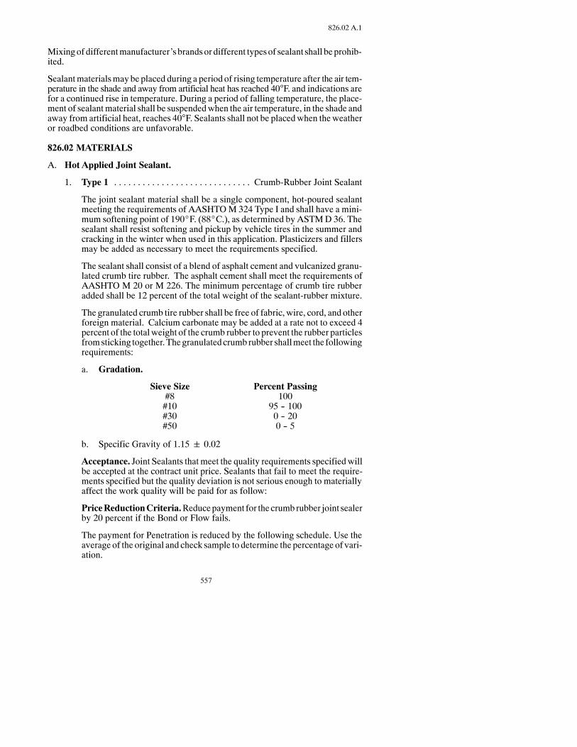
557
826.02 A.1
Mixingof differentmanufacturer’s brandsor different typesof sealant shall beprohib-ited.
Sealantmaterialsmay be placed during a period of rising temperature after the air tem-perature in the shade and away from artificial heat has reached 40°F. and indications arefor a continued rise in temperature. During a period of falling temperature, the place-ment of sealantmaterial shall be suspendedwhen the air temperature, in the shade andaway from artificial heat, reaches 40°F. Sealants shall not be placedwhen theweatheror roadbed conditions are unfavorable.
826.02 MATERIALS
A. Hot Applied Joint Sealant.
1. Type 1 Crumb-Rubber Joint Sealant. . . . . . . . . . . . . . . . . . . . . . . . . . . . .
The joint sealant material shall be a single component, hot-poured sealantmeeting the requirements of AASHTOM 324 Type I and shall have a mini-mum softening point of 190_F. (88_C.), as determined by ASTMD 36. Thesealant shall resist softening and pickup by vehicle tires in the summer andcracking in the winter when used in this application. Plasticizers and fillersmay be added as necessary to meet the requirements specified.
The sealant shall consist of a blend of asphalt cement and vulcanized granu-lated crumb tire rubber. The asphalt cement shall meet the requirements ofAASHTO M 20 or M 226. The minimum percentage of crumb tire rubberadded shall be 12 percent of the total weight of the sealant-rubber mixture.
The granulated crumb tire rubber shall be free of fabric, wire, cord, and otherforeign material. Calcium carbonate may be added at a rate not to exceed 4percent of the total weight of the crumb rubber to prevent the rubber particlesfromsticking together.Thegranulatedcrumbrubber shallmeet the followingrequirements:
a. Gradation.
Sieve Size Percent Passing#8 100#10 95 -- 100#30 0 -- 20#50 0 -- 5
b. Specific Gravity of 1.15 0.02
Acceptance. Joint Sealants that meet the quality requirements specifiedwillbe accepted at the contract unit price. Sealants that fail to meet the require-ments specified but the quality deviation is not serious enough to materiallyaffect the work quality will be paid for as follow:
PriceReductionCriteria.Reducepayment for thecrumbrubber joint sealerby 20 percent if the Bond or Flow fails.
The payment for Penetration is reduced by the following schedule. Use theaverage of the original and check sample to determine the percentage of vari-ation.
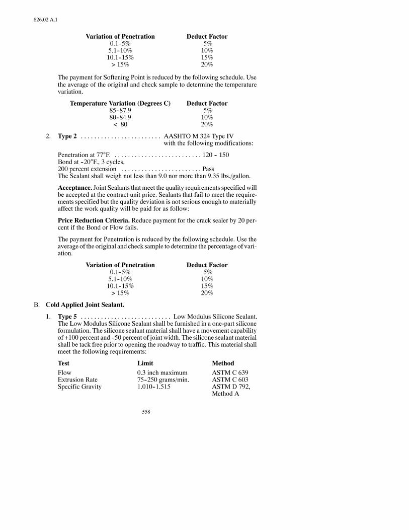
558
826.02 A.1
Variation of Penetration Deduct Factor0.1--5% 5%5.1--10% 10%10.1--15% 15%> 15% 20%
The payment for Softening Point is reduced by the following schedule. Usethe average of the original and check sample to determine the temperaturevariation.
Temperature Variation (Degrees C) Deduct Factor85--87.9 5%80--84.9 10%< 80 20%
2. Type 2 AASHTO M 324 Type IV. . . . . . . . . . . . . . . . . . . . . . . .with the following modifications:
Penetration at 77°F. 120 -- 150. . . . . . . . . . . . . . . . . . . . . . . . . .Bond at --20°F., 3 cycles,200 percent extension Pass. . . . . . . . . . . . . . . . . . . . . . . .The Sealant shall weigh not less than 9.0 nor more than 9.35 lbs./gallon.
Acceptance. Joint Sealants that meet the quality requirements specifiedwillbe accepted at the contract unit price. Sealants that fail to meet the require-ments specified but the quality deviation is not serious enough to materiallyaffect the work quality will be paid for as follow:
Price Reduction Criteria. Reduce payment for the crack sealer by 20 per-cent if the Bond or Flow fails.
The payment for Penetration is reduced by the following schedule. Use theaverage of the original and check sample to determine the percentage of vari-ation.
Variation of Penetration Deduct Factor0.1--5% 5%5.1--10% 10%10.1--15% 15%> 15% 20%
B. Cold Applied Joint Sealant.
1. Type 5 Low Modulus Silicone Sealant.. . . . . . . . . . . . . . . . . . . . . . . . . . .The LowModulus Silicone Sealant shall be furnished in a one-part siliconeformulation. The silicone sealant material shall have a movement capabilityof +100 percent and --50 percent of joint width. The silicone sealantmaterialshall be tack free prior to opening the roadway to traffic. This material shallmeet the following requirements:
Test Limit MethodFlow 0.3 inch maximum ASTM C 639Extrusion Rate 75--250 grams/min. ASTM C 603Specific Gravity 1.010--1.515 ASTM D 792,
Method A
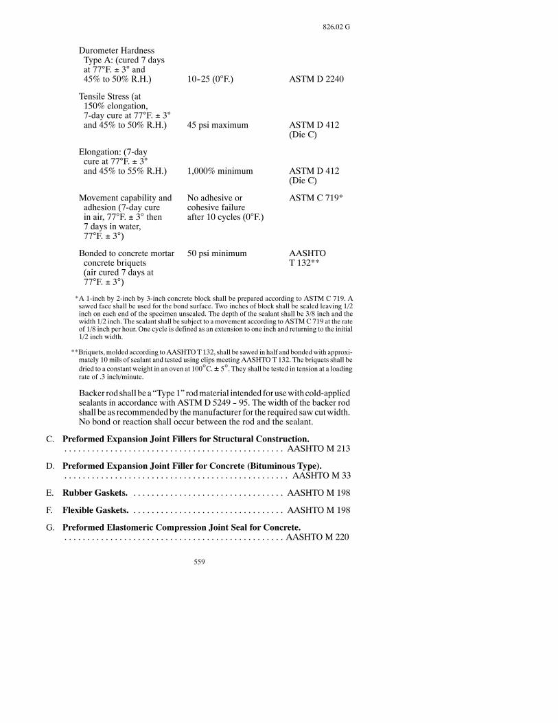
559
826.02 G
Durometer HardnessType A: (cured 7 daysat 77°F. ± 3° and45% to 50% R.H.) 10--25 (0°F.) ASTM D 2240
Tensile Stress (at150% elongation,7-day cure at 77°F. ± 3°and 45% to 50% R.H.) 45 psi maximum ASTM D 412
(Die C)
Elongation: (7-daycure at 77°F. ± 3°and 45% to 55% R.H.) 1,000% minimum ASTM D 412
(Die C)
Movement capability and No adhesive or ASTM C 719*adhesion (7-day cure cohesive failurein air, 77°F. ± 3° then after 10 cycles (0°F.)7 days in water,77°F. ± 3°)
Bonded to concrete mortar 50 psi minimum AASHTOconcrete briquets T 132**(air cured 7 days at77°F. ± 3°)
*A 1-inch by 2-inch by 3-inch concrete block shall be prepared according to ASTM C 719. Asawed face shall be used for the bond surface. Two inches of block shall be sealed leaving 1/2inch on each end of the specimen unsealed. The depth of the sealant shall be 3/8 inch and thewidth 1/2 inch. The sealant shall be subject to a movement according to ASTMC 719 at the rateof 1/8 inch per hour. One cycle is defined as an extension to one inch and returning to the initial1/2 inch width.
**Briquets,molded according toAASHTOT132, shall be sawed in half and bondedwith approxi-mately 10 mils of sealant and tested using clips meeting AASHTO T 132. The briquets shall bedried to a constant weight in an oven at 100°C.± 5°. They shall be tested in tension at a loadingrate of .3 inch/minute.
Backer rod shall be a“Type1” rodmaterial intended forusewithcold-appliedsealants in accordance with ASTMD 5249 -- 95. The width of the backer rodshall be as recommended by themanufacturer for the required sawcutwidth.No bond or reaction shall occur between the rod and the sealant.
C. Preformed Expansion Joint Fillers for Structural Construction.AASHTO M 213. . . . . . . . . . . . . . . . . . . . . . . . . . . . . . . . . . . . . . . . . . . . . . . .
D. Preformed Expansion Joint Filler for Concrete (Bituminous Type).AASHTO M 33. . . . . . . . . . . . . . . . . . . . . . . . . . . . . . . . . . . . . . . . . . . . . . . . .
E. Rubber Gaskets. AASHTO M 198. . . . . . . . . . . . . . . . . . . . . . . . . . . . . . . . .
F. Flexible Gaskets. AASHTO M 198. . . . . . . . . . . . . . . . . . . . . . . . . . . . . . . . .
G. Preformed Elastomeric Compression Joint Seal for Concrete.AASHTO M 220. . . . . . . . . . . . . . . . . . . . . . . . . . . . . . . . . . . . . . . . . . . . . . . .

560
830.01
SECTION 830PIPE
830.01 CONCRETE PIPE.
TheDepartmentwill evaluate the fabricator’s concrete pipe plant according toDepart-ment procedures. The results of this evaluation will determine if the material may beaccepted by “Certificate of Compliance.” The results of tests shall govern acceptanceor rejection of materials tested.
A. Concrete Sewer, Storm Drain, and Culvert Pipe. AASHTO M 86. . . . . . .
B. Reinforced Concrete Culvert, Storm Drain, and Sewer Pipe. This pipe shallmeetAASHTOM-170,M-206, orM-207 for the specifieddiameters and strengthclass except that aggregate shallmeet the requirementsofSection816.01A.2. and816.02 A.2.
C. Precast Reinforced Concrete Manhole Sections. . . AASHTO M 199. . . . .
D. Fasteners and Tie Bolts. Tie bolts and nuts shall be of steel meeting ASTM A307 Grade A. Washers shall be of steel meeting ASTM A 366 or ASTM A 569.Fastener castings shall be gray iron castings meeting ASTM A 48 Class 20.
830.02 METAL PIPE.
A. Ductile Iron Sewer Pipe. ASTM A 746. . . . . . . . . . . . . . . . . . . . . . . . . . . . . .
B. Metallic (Zinc or Aluminum) Coated Corrugated Steel Culverts, StormDrains, and Underdrains. AASHTO M 36. . . . . . . . . . . . . . . . . . . . . . . . . . .
C. Corrugated AluminumAlloy Culverts and Underdrains. AASHTO M 196
D. Smooth Wall Steel Pipe Culvert.Smoothwall steelpipeculvert shall beweldedsteel pipe of newmaterial, meeting ASTMSpecifications A 139, Grade B with aminimum yield strength of 35,000 psi. The following minimum wall thicknessshall be used:
Diameterof Pipe
MinimumWall ThicknessThrough RoadwayEmbankment
MinimumWall ThicknessThrough RailroadEmbankment
24 inches30 inches36 inches
0.250 inch0.312 inch0.375 inch
0.344 inch0.406 inch0.469 inch
E. Structural Plate For Pipe, Pipe Arches, and Arches. AASHTO M 167. . .

561
830.03 C
F. AluminumAlloy Structural Plate for Pipe, Pipe Arches, and Arches.AASHTO M 219. . . . . . . . . . . . . . . . . . . . . . . . . . . . . . . . . . . . . . . . . . . . . . . .
G. Polymer-Coated Corrugated Steel Pipe
1. Steel Pipe. AASHTO M 246. . . . . . . . . . . . . . . . . . . . . . . . . . . . . . . . . . .
2. Polymer-Coated Corrugated Steel Pipe. AASHTO M 245. . . . . . . . . .
All Polymer-Coated Corrugated Steel Pipe shall have helical corrugationswith a continuous lock seam extending the length of each pipe.
All pipe ends shall be re-rolled to form annular corrugations extending atleast two corrugations from the pipe end to facilitate field jointing.
3. Coupling Bands. AASHTO M 246. . . . . . . . . . . . . . . . . . . . . . . . . . . . . .
The coupling bands shall conform with the same polymer coating grade asthat used for fabrication of the polymer-coated corrugated steel pipe, andhaving the same metallic coating.
830.03 PLASTIC PIPE.
A. Plastic Pipe for Non-Pressure Drainage of Sewage and Surface Water (out-side buildings). Plastic pipe for non-pressure drainage of sewage and surfacewater shall meet the following:
1. Acrylonitrile-Butadiene-Styrene (ABS). ASTM D 2680. . . . . . . . . . . .
2. Acrylonitrile-Butadiene-Styrene (ABS). ASTM D 2751. . . . . . . . . . . .
3. Type PSM, Polyvinyl Chloride (PVC). ASTM D 3034. . . . . . . . . . . . .or. . . . . . . . . . . . . . . . . . . . . . . . . . . . ASTM F 949. . . . . . . . . . . . . . . . .
4. Perforated, Corrugated, P.E., or Plastic Pipe. AASHTO M 252. . . . .
B. Plastic Pipe forWater Distribution Lines (outside buildings). Plastic pipe forwater distribution lines shall meet the following:
1. Acrylonitrile-Butadiene-Styrene (ABS). ASTM D 1527. . . . . . . . . . . .Schedules 40 and 80.
2. Polyethylene (PE). ASTM D 2104, Schedule 40. . . . . . . . . . . . . . . . . . .
3. Polyvinyl Chloride (PVC) and Chlorinated Polyvinyl Chlorid (CPVC)Plastic Pipe (SDR-PR). The PVC and CPVC compounds shall meetASTM D 1784 and shall be Class 12454-B (Type 1, Grade 1).
4. Polybutylene (PB) Plastic Pipe (SDR-PR) ASTM D 2662. . . . . . . . . . .
C. Plastic Drain, Waste and Vent (DWV) Pipe and Fittings. Plastic drain,waste, and vent pipe and fittings shall meet the following:
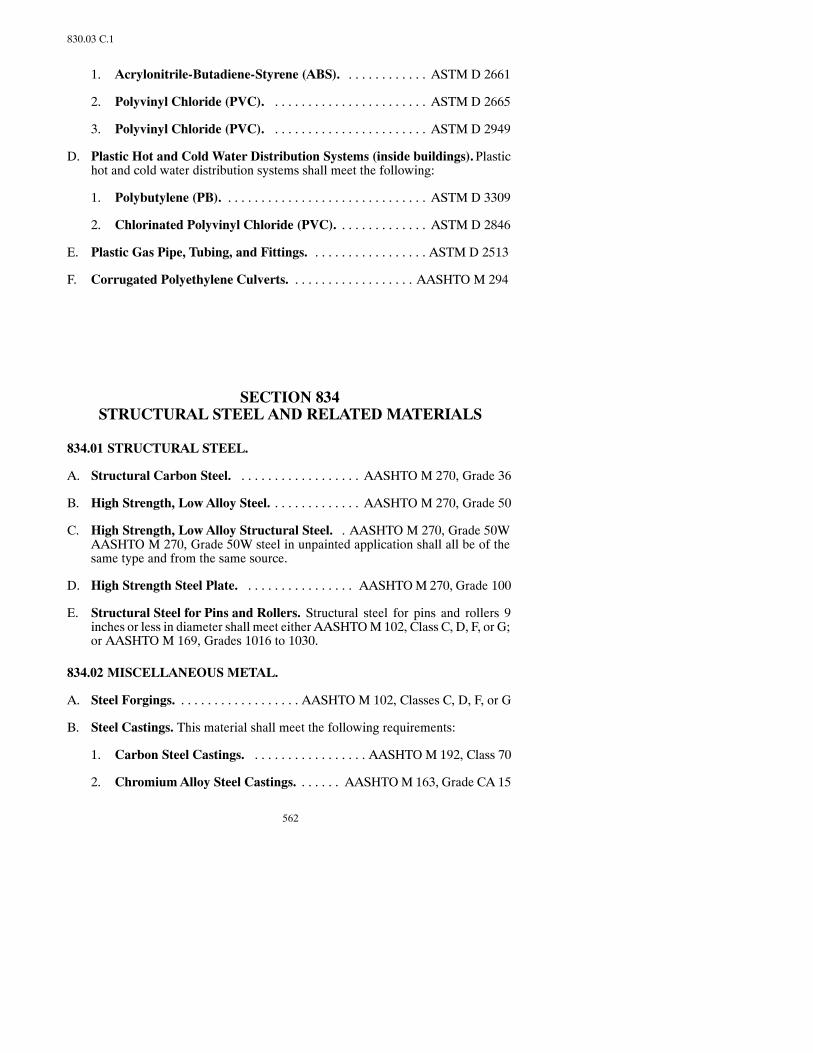
562
830.03 C.1
1. Acrylonitrile-Butadiene-Styrene (ABS). ASTM D 2661. . . . . . . . . . . .
2. Polyvinyl Chloride (PVC). ASTM D 2665. . . . . . . . . . . . . . . . . . . . . . .
3. Polyvinyl Chloride (PVC). ASTM D 2949. . . . . . . . . . . . . . . . . . . . . . .
D. Plastic Hot and Cold Water Distribution Systems (inside buildings).Plastichot and cold water distribution systems shall meet the following:
1. Polybutylene (PB). ASTM D 3309. . . . . . . . . . . . . . . . . . . . . . . . . . . . . .
2. Chlorinated Polyvinyl Chloride (PVC). ASTM D 2846. . . . . . . . . . . . .
E. Plastic Gas Pipe, Tubing, and Fittings. ASTM D 2513. . . . . . . . . . . . . . . . .
F. Corrugated Polyethylene Culverts. AASHTO M 294. . . . . . . . . . . . . . . . . .
SECTION 834STRUCTURAL STEEL AND RELATED MATERIALS
834.01 STRUCTURAL STEEL.
A. Structural Carbon Steel. AASHTO M 270, Grade 36. . . . . . . . . . . . . . . . . .
B. High Strength, LowAlloy Steel. AASHTO M 270, Grade 50. . . . . . . . . . . . .
C. High Strength, LowAlloy Structural Steel. AASHTO M 270, Grade 50W.AASHTO M 270, Grade 50W steel in unpainted application shall all be of thesame type and from the same source.
D. High Strength Steel Plate. AASHTOM270, Grade 100. . . . . . . . . . . . . . . .
E. Structural Steel for Pins and Rollers. Structural steel for pins and rollers 9inches or less in diameter shall meet either AASHTOM102, Class C, D, F, or G;or AASHTO M 169, Grades 1016 to 1030.
834.02 MISCELLANEOUS METAL.
A. Steel Forgings. AASHTO M 102, Classes C, D, F, or G. . . . . . . . . . . . . . . . . .
B. Steel Castings. This material shall meet the following requirements:
1. Carbon Steel Castings. AASHTOM 192, Class 70. . . . . . . . . . . . . . . . .
2. ChromiumAlloy Steel Castings. AASHTOM 163, Grade CA 15. . . . . .

563
834.03 B.1.b.(2)
C. Gray Iron Castings. AASHTOM 105, Class 35 B. . . . . . . . . . . . . . . . . . . . .
D. Malleable Castings. ASTM A 47, Grade No. 35018. . . . . . . . . . . . . . . . . . . .
E. Ductile Iron Castings. ASTMA 536, Grade 60-40-18. . . . . . . . . . . . . . . . . .
F. Bronze Bearing and Expansion Plates. AASHTO M 107, Alloys C-91300 orC-91100
G. Rolled CopperAlloy Bearings and Expansion Plates. AASHTO M 108. .
H. Cast Aluminum. AASHTO M 193. . . . . . . . . . . . . . . . . . . . . . . . . . . . . . . . .
I. Lead Sheets and Plates. ASTM B 29, Common Lead. . . . . . . . . . . . . . . . . .
J. Brass Sheets. ASTM B 36. . . . . . . . . . . . . . . . . . . . . . . . . . . . . . . . . . . . . . . .
K. Copper Sheets. AASHTO M 138. . . . . . . . . . . . . . . . . . . . . . . . . . . . . . . . . . .
834.03 BOLTS, NUTS, ANDWASHERS.
A. Unfinished Regular Bolts and Nuts. ASTM A 307. . . . . . . . . . . . . . . . . . . .
B. High Tensile Strength Bolts, Nuts, and Washers.
All bolts shall meet AASHTO M 164 and these revisions.
All nuts shall meet AASHTOM292 as applicable or AASHTOM291 and theserevisions.
All washers shall meet AASHTO M 293 and these revisions.
1. Manufacturing.
a. Bolts.
(1) Hardness for bolt diameters 1/2 inch to 1 inch inclusive shall be asnoted below:
Hardness Number
Bolt Size, In. Brinell Rockwell CMin. Max. Min. Max.
1/2 to 1 inch 248 311 24 33
b. Nuts.
(1) Nuts to be galvanized (hot dip ormechanically galvanized) shall beheat treated grade 2H, DH, or DH3.
(2) Plain (ungalvanized) nuts shall be grades 2,C,D, orC3with amini-mumRockwell hardness of 89 HRB (or Brinell hardness 180 HB),or heat treated grades 2H, DH, or DH3.

564
834.03 B.1.b.(3)
(3) Nuts that are to begalvanized shall be tappedoversize theminimumamount required for proper assembly. The amount of overtap in thenut shall be so the nut assembles freely on the bolt in the coated con-dition and shall meet the mechanical requirements of AASHTOM291and the rotational-capacity test herein (the overtapping require-ments ofAASHTOM291, paragraph7.4 shall be consideredmaxi-mum values instead of minimum, as currently shown).
(4) Galvanizednuts shall be lubricatedwitha lubricant containingadyeof any color that contrasts with the color of the galvanizing.
c. Marking.All bolts, nuts, and washers shall be marked according to theappropriate AASHTO Specifications.
2. Testing.
a. Bolts.
(1) Proof load tests (ASTM F 606, Method 1) are required. Minimumfrequency of tests shall be as specified in AASHTO M 164, para-graph 9.2.4.
(2) Wedge tests on full size bolts (ASTM F 606 paragraph 3.5) are re-quired. If bolts are to be galvanized, tests shall be performed aftergalvanizing. Minimum frequency of tests shall be as specified inAASHTO M 164, paragraph 9.2.4.
(3) If galvanized bolts are supplied, the thickness of the zinc coatingshall bemeasured.Measurements shall be takenon thewrench flats,or top of bolt head.
b. Nuts.
(1) Proof load tests (ASTM F 606, paragraph 4.2) are required. Mini-mum frequency of tests shall be as specified in AASHTO M 292,paragraph 7.1.2.1. If nuts are to be galvanized, tests shall be per-formed after galvanizing, overtapping, and lubricating.
(2) If galvanized nuts are supplied, the thickness of the zinc coatingshall bemeasured.Measurements shall be takenon thewrench flats.
c. Washers.
(1) If galvanized washers are supplied, hardness testing shall be per-formed after galvanizing. (Coating shall be removed before takinghardness measurements.)
(2) If galvanizedwashers are supplied, the thickness of the zinc coatingshall be measured.
d. Assemblies.
Rotational-capacity tests are required and shall be performed on allblack or galvanized (after galvanizing) bolt, nut, andwasher assemblies

565
834.03 B.2.d.(8)
by the manufacturer or distributor prior to shipping. Washers are re-quired as part of the test even though theymay not be required as part ofthe installation procedure.
The following shall apply:
(1) Except as modified herein, the rotational-capacity test shall be per-formed according to AASHTO M 164.
(2) Each combination of bolt production lot, nut lot, and washer lotshall be tested as an assembly. Where washers are not required bythe installationprocedures, theyneednot be included in the lot iden-tification.
(3) Arotational-capacity lot number shall be assigned to eachcombina-tion of lots tested.
(4) Theminimumfrequencyof testing shall be twoassemblies per rota-tional-capacity lot.
(5) The bolt, nut, andwasher assembly shall be assembled in a Skidmore-Wilhelm Calibrator or an acceptable equivalent device. For shortbolts which are too short to be assembled in the Skidmore-WilhelmCalibrator, see Section 834.03 B.2.d.9.
(6) The minimum rotation, from a snug tight condition (10 percent ofthe specified proof load), shall be:
240 degrees (2/3 turn) for bolt lengths < 4 diameters360 degrees (1 turn) for bolt lengths > 4 diameters and< 8 diameters480 degrees (1-1/3 turn) for bolt lengths > 8 diameters
(7) The tension reached at the above rotation shall be equal to or greaterthan 1.15 times the required installation tension. The installationtension and the tension for the turn seat are shown below:
Diameter (In.) 1/2 5/8 3/4 7/8 1 1-1/8 1-1/4 1-3/8 1-1/2Req. InstallationTension (kips) 12 19 28 39 51 56 71 85 103Turn TestTension (kips) 12 22 32 45 59 64 82 98 118
(8) After the required installation tension listed above has been ex-ceeded, one reading of tension and torque shall be taken and re-corded. The torque value shall meet the following:
Torque: less than or equal to 0.25 PD
Where:
Torque = measured torque (foot-pounds)P = measured bolt tension (pounds)D = bolt diameter (feet)
566
834.03 B.2.d.(9)
(9) Bolts that are too short to test in a Skidmore-Wilhelm Calibratormay be tested in a steel joint. The tension requirement of Sec-tion 834.03 B.2.d.7 need not apply. The maximum torque require-mentofSection 834.03B.2.d.8 shall be computedusingavalueofPequal to the turn test tension shown in the table in Section 834.03B.2.d.7.
e. Reporting.
(1) The results of all tests (including zinc coating thickness) requiredherein and in the appropriate AASHTO Specifications shall be re-corded on the appropriate document.
(2) Location where tests are performed and date of tests shall be re-ported on the appropriate document.
f. Witnessing.
The tests need not be witnessed by an inspection agency; however, themanufacturer or distributor that performs the tests shall certify that theresults recorded are accurate.
3. Documentation.
a. Mill Test Report(s) (MTR).
(1) MTR shall be furnished for all mill steel used in the manufacture ofbolts, nuts, or washers.
(2) MTR shall indicate the place where the material was melted andmanufactured.
b. Manufacturer Certified Test Report(s) (MCTR).
(1) The manufacturer of the bolts, nuts, and washers shall furnish testreports (MCTR) for the item furnished.
(2) Each MCTR shall show the relevant information required accord-ing to Section 834.03 B.2.e.
(3) The manufacturer performing the rotational-capacity test shall in-clude on the MCTR:
(a) The lot number of each of the items tested.
(b) The rotational-capacity lot number as required in Sec-tion 834.03 B.2.d.3.
(c) The results of the tests required in Section 834.03 B.2.d.
(d) The pertinent information required in Section 834.03 B.2.e.2.
(e) A statement that MCTR for the items meet this Specificationand the appropriate AASHTO Specification.
567
836.01
(f) The locationwhere the bolt assembly components weremanu-factured.
c. Distributor Certified Test Report(s) (DCTR).
(1) TheDCTRshall includeMCTRabove for thevariousbolt assemblycomponents.
(2) The rotational-capacity test may be performed by a distributor (inlieu of a manufacturer) and reported on the DCTR.
(3) The DCTR shall show the results of the tests required in Sec-tion 834.03 B.2.d.
(4) The DCTR shall also show the pertinent information required inSection 834.03 B.2.e.2.
(5) The DCTR shall show the rotational-capacity lot number as re-quired in Section 834.03 B.2.d.3.
(6) The DCTR shall certify that theMCTR are conforming to this Spe-cification and the appropriate AASHTO specifications.
4. Shipping.
a. Bolts, nuts, andwashers (where required) from each rotational-capacitylot shall be shipped in the same container. If there is only one productionlot number for each size of nut andwasher, the nuts andwashersmay beshipped in separate containers. Each container shall be permanentlymarked with the rotational-capacity lot number such that identificationwill be possible at any stage prior to installation.
b. The appropriate MTR, MCTR, or DCTR shall be supplied to the Engi-neer for acceptance prior to installation.
C. Direct Tension Indicators. ASTM F 959. . . . . . . . . . . . . . . . . . . . . . . . . . . .
834.04 PERMANENT METAL CONCRETE FORMS.
Permanent metal forms for concrete floor slabs shall be of zinc-coated (galvanized)steel sheetsmeetingASTMA924with coating class ofG235 according toASTMA635.
SECTION 836REINFORCING STEEL
836.01 HEAT NUMBERS.
All reinforcement delivered to a Project shall be tagged with a metal or plastic tagshowing the manufacturer’s heat number. Numbers shall be embossed, engraved, orprinted in waterproof ink.
568
836.02
836.02 BARS.
A. Deformed and Plain Billet Bars for Concrete Reinforcement.AASHTO M 31, Grade 40 or 60. . . . . . . . . . . . . . . . . . . . . . . . . . . . . . . . . . . .
B. Epoxy Coated Reinforcing Bars. AASHTO M 284. . . . . . . . . . . . . . . . . . . .
C. Fabricated Steel Bar or Rod Mats for Concrete Reinforcement.AASHTO M 54, Grade 40 or 60. . . . . . . . . . . . . . . . . . . . . . . . . . . . . . . . . . . .
836.03 WIRES.
A. Welded Deformed Steel Wire Fabric. AASHTO M 221. . . . . . . . . . . . . . . .
B. Deformed Steel Wire for Concrete Reinforcement. AASHTO M 225. . . .
C. Welded Steel Wire Fabric. AASHTO M 55. . . . . . . . . . . . . . . . . . . . . . . . . .
D. Cold Drawn Steel Wire for Concrete Reinforcement. AASHTO M 32. . .
E. High Tensile Wire Strand and Bars.
1. Post-tensioning Steel. For the post-tensioning method of construction, theprestressing steel shall be high-tensile wire, high-tensile wire strand or rope,or high-tensile alloy bars, uncoated and stress relieved.
High-tensilewire shallmeetAASHTOM204andhigh-tensilewire strandorrope shall meet AASHTO M 203. High-tensile alloy bars shall meetAASHTO M 275.
2. Pre-Tensioning Steel. AASHTO M 203. . . . . . . . . . . . . . . . . . . . . . . . .
836.04 DOWEL BARS AND TIE BARS FOR PAVEMENT JOINTS.
Dowel bar for transverse expansion or contraction joints in PortlandCementConcretepavement shall be plain, round bars fabricated from steel meeting AASHTO M 31 orM 322.
Dowels shall be saw cut to the required length and cleaned to remove all cutting burrs,loosemill scale, rust, grease, and oil. The barsmay be sheared providing the deforma-tion of the bars from true round shape does not exceed 0.04 inch in diameter or thick-ness, and shall not extend more than 0.04 inch from the sheared end.
The free end of dowels for expansion joints shall be fitted with a metal sleeve of anapproveddesigncovering2 inches±1 inchof thedowel.The sleeve shall have aclosedendanda stop tohold the closedendat least one inch fromthe endof thedowel bar.Thesleeve shall not collapse or distort in shape in handling and placing of the dowels andconcrete.
All dowels shall be Epoxy coated in accordance with AASHTO M 284. Freshly ex-posed steel as a result of shearing, saw-cutting, or cutting by other means during thefabrication process is acceptable on the ends of tie or dowel bars used in pavementjoints.

569
840.03 B
Tie bars for the centerline joint and adjoining driving lanes in Portland Cement Con-crete pavement shall be epoxy coated,meeting the requirements in 836.02B.All othertie bars shall meet AASHTO M 31, Grade 40 deformed.
SECTION 840PILING
840.01 STEEL PILING.
A. Steel H-Piling and Special Sections.Materials for steel piling and special sec-tions shall meet AASHTO 270 Grade 50.
B. Shells for Steel Encased Concrete Piling.Shells for steel encased concrete pil-ing may be either cylindrical pipe or tapered fluted.
Cylindrical pipe shells shall be electric welded steel pipe or seamless steel pipeand shall meet ASTMA 252, Grade 2. End closure plates shall be 3/4-inch flatsteel plateweldeddirectly to thepipe and shall not project beyond the perimeter ofthe pile.
840.02 TIMBER PILING.
A. Requirements. All Timber Piling shall be clean-peeled and meet ASTM D 25.
B. Dimensions. Piles shall have the following minimum diameters:
Length of Piles 3 Feet from Butt At TipDiameter (Inches)
Under 40 feet40 -- 74 feet75 -- 90 feetOver 90 feet
121313
876
As shown on the Plans
C. Treatment.Where required, treatment of timber piling shall be according to Sec-tion 846 and will be accepted on certification according to Section 801.01. Thiscertificate shall include species of timber, type of preservative, and method oftreatment.
840.03 SHEET PILING FOR PERMANENT INSTALLATION.
A. Steel Sheet Piling. This material shall meet AASHTO M 202.
B. Corrugated Steel Sheet Piles. The steel sheet piles shall be of the continuous in-terlock type and of the lengths and sectionmodulus specified. The sheeting shallbe new and the base metal shall be open hearth steel.

570
840.03 B
The interlock shall be formed by bending themetal through 180 degrees ormore,leaving an opening of sufficient size to allow free slippage of the adjoining sheetpile, but maintaining a reasonably snug fit.
Eachsheetpile shall be true, straight, anduniformin section.Corner sections shallbe of the same section modulus and metal as the regular sections.
When required, galvanizing shallmeetASTMA525CoatingDesignationG210.
SECTION 844STRUCTURAL TIMBER, LUMBER, AND HARDWARE
844.01 STRUCTURAL TIMBER AND LUMBER.
This material shall meet AASHTO M 168.
844.02 HARDWARE.
A. Timber Connectors.The dimensions and types of all connectors shall be shownin the Contract. The materials for connectors shall be as follows:
1. Split Ring, ToothRing, andShear PlateConnectors shallmeetASTMA711.
2. Spike Grid Connectors shall meet ASTM A 47, Grade 35018.
3. All connectors, except those ofmalleable iron, shall be galvanized accordingto AASHTO M 111.
B. Hardware.Bolts, rods, drift-bolts, and dowelsmaybe eitherwrought iron orme-dium steel. Washers shall be made integral with the heads and nuts and their di-ameters shall be at least four times the diameter of the respective bolts. Hardware,nails, and spikes shall be galvanized according to AASHTO M 232.
SECTION 846PRESERVATIVES AND PRESSURE TREATMENT
PROCESSES FOR TIMBER
846.01 TIMBER PRESERVATIVES.
This material shall meet AASHTO M 133.

571
854.01
SECTION 848MASONRY UNITS AND BRICK
848.01 MATERIALS.
A. Concrete Masonry Units for Construction of Catch Basins and ManholesASTM C 139. . . . . . . . . . . . . . . . . . . . . . . . . . . . . . . . . . . . . . . . . . . . . . . . . . .
B. Building Brick (Made from Clay or Shale). AASHTO M 114. . . . . . . . . . .
SECTION 852PAINTS, OILS, AND THINNERS
852.01 MATERIALS.
Paints, oils, and thinners shall meet the following:
A. Aluminum Paint. AASHTO M 69. . . . . . . . . . . . . . . . . . . . . . . . . . . . . . . . . .
B. Lamp Black. ASTM D 209. . . . . . . . . . . . . . . . . . . . . . . . . . . . . . . . . . . . . . .
C. Chrome Yellow and Chrome Orange. ASTM D 211. . . . . . . . . . . . . . . . . . .
D. Enamels. The enamel shall meet the general requirements of Federal Specifica-tions TT-E-529 Enamel, Alkyd, Semi-Gloss (Class A Air-drying) with the fol-lowing exceptions:
1. Alkyd resin shall be an alkyd meeting Federal Specification TT-R-266aResin, Alkyd (Type I or Type II).
2. Specular gloss, 60 degrees, shall be in the range of 40 to 70.
SECTION 854GALVANIZING
854.01 GALVANIZING.
Galvanizing shall meet AASHTO M 111 or AASHTO M 232.
572
854.02
854.02 DAMAGED GALVANIZED COATINGS.
Repair of damaged galvanized coatings shall meet ASTM A 780.
SECTION 856EROSION CONTROL BLANKET AND
TURF REINFORCEMENT MAT
856.01 EROSION CONTROL FABRIC.
The erosion control blanket (ECB) shall be of organic biodegradable mulch materialsuchas straw, curledwoodexcelsior, coconut fiber, or anycombinationof thesemater-ials. The ECB shall have a consistent thickness of mulch material evenly distributedover the entire area. The ECB materials must be secured on at least one side withnetting. The nettingmust be of photodegradable polypropylene or other plasticmater-ial fused to the strand intersections. The ECB shall be a minimumwidth of 48 inchesand shall be weed and pest free.
A. WoodExcelsiorBlanket.Thewoodexcelsior blanket shall consist of amachine-produced blanket of cured wood excelsior in which 80 percent of the fibers are 6inches or longer. The wood excelsior blanket shall be smolder-resistant withoutusing additives.
B. StrawBlanket.The strawblanket shall consist of amachine-produced blanket of100 percent certified weed-free agricultural straw by an accredited agency inwhich 80 percent of the fibers are 3 inches or longer.
C. Straw and Coconut Blanket. The straw and coconut blanket shall consist of amachine-produced blanket of 70 percent straw and 30 percent coconut fibers byweight in which 80 percent of the fibers are 3 inches or longer.

573
856.02
Material
Fiber Length 80%Must Be Greater
Than
Min Mass PerUnit Area
ASTM D 6475
Min ThicknessASTM D 6525
Net OpeningMinimum
Max Shear Stress@ 0.50 inches soil
lossASTM D 6460
Slope GradientApplication
Net BackingType
FunctionalLongevity
Min MachineDirection Tensile
StrengthASTM D 6818
TYPE
TABLE 856--1EROSION CONTROL BLANKET
ECB 1 ECB 2 ECB 3 ECB 4
Straw Wood Straw Wood Coconut WoodWoodStraw/Coconut
100%Straw
100%Straw
100%ExcelsiorFibers
100%ExcelsiorFibers
100%ExcelsiorFibers
100%ExcelsiorFibers
100%CoconutFibers
70% Straw and30% Coconut
Fibers
3 inches 3 inches80%>6 inches 6 inches 80%>
6 inches80%>6 inches3 inches3 inches
0.5lbs/sy
0.5lbs/sy
0.51lbs/sy
0.51lbs/sy
0.69lbs/sy
0.88lbs/sy
0.5lbs/sy
0.5lbs/sy
0.25inch
0.25inch
0.25inch
0.25inch
0.25inch
0.25inch
0.25inch
0.50inch
0.5×0.5inch
0.75×0.75inch
0.5×0.5inch
0.75×0.75inch
0.5×0.5inch
0.75×0.75inch
0.6×0.6inch
0.75×0.75inch
1.50lbs/sy
1.50lbs/sy
1.75lbs/sy
2.0lbs/sy
2.25lbs/sy
2.25lbs/sy
1.75lbs/sy
≤3H:1V <3H:1V--2H:1V ≤2H:1V 2H:1V--
1.5H:1V ≤1.5H:1V ≤1.5H:1V ≤1H:1V ≤1H:1V
RapidPhotodegradablePolypropylene
Polypropylene PolypropyleneBlack UVStabilized
Polypropylene
≤ 3 months ≤ 12 months 12 to 24 months > 24 months
50 lbs/ft 75 lbs/ft 100 lbs/ft 125 lbs/ft
The information in this table has been derived from information obtained from theErosion Control Technology Council. All values must be with 10 percent of theminimums shown on the table.
856.02 TURF REINFORCEMENT MAT.
The turf reinforcement mat (TRM) shall be three dimensional structure of entangledfilaments. The filaments shall either be bonded by heat fusion and the intersections orstitchedwith polypropylene, a nylon or polyester threads between twoUV-Stabilizednettings. TheTRMshall be resistant to biological, chemical, environmental, andultra-violet degradation. TheTRMshall promote andmaintain the integrity of the grass rootsystem.

574
856.02
TABLE 856--2TURF REINFORCEMENT MAT
TYPE TRM 1 TRM 2
Matrix Fill Material Wood Excelsior, Coconut orPolymer Fibers
100% StabilizedPolypropylene Fibers
Min Mass Unit AreaASTM D 6475(natural fibers)6566 (synthetics)
0.625 lbs/sy 0.625 lbs/sy
Minimum ThicknessASTM D 6525 0.25 inch 0.5 inch
Minimum Roll WidthMinimum Roll Width
Size of Net Opening
6.5 ft 6.5 ft
0.5 × 0.5 inch 0.5 × 0.5 inch
Max Shear Stress@ 0.50 inches
soil loss ASTM D 6460,under vegetated conditions
Minimum Tensile StrengthASTM D 6818 125 lbs/ft 150 lbs/ft
6.0 lbs/sf 8.0 lbs/sf
856.03 STAPLES.
Staples for ECM and TRM shall be constructed of 11 gauge or heavier steel wire andshall be either U-shaped measuring at least 1 inch across the top and at least 8 inchesalong each leg, or shall be T-shaped measuring at least 4 inches across the top and atleast 8 inches in length.
856.04 FABRIC FORMED SLOPE PROTECTION.
Fabric forming material shall consist of specially woven, double-layer, open salvagefabric joined in a mat configuration. The fabric shall consist of uncoated syntheticyarnswith sufficient tensile strengthandporosity towithstand thepressureof thegroutinjection pump without breaking the layers of fabric.
Spacer threads capable of a tensile strength of at least 8.0 psi of surface area shall bewoven between the layers at the required distance to control the mat thickness.

575
858.01
SECTION 858GEOTEXTILE FABRICS
858.01 GENERAL.
Geotextile fabric shall be a fabric consisting of polymeric filament or yarns such aspolypropylene, polyethylene, polyester, polyamide, or polyvinylidene chloride. Thefilaments or yarns shall be formed into a stable network so they retain their relativeposition to each other. The geotextile shall be inert to commonly encountered chemi-cals and meet the properties in the following table:
A. Geotextile Fabrics.
Grab TensileStrength1), lbs.,min.
Grab TensileElongation, %,min.
Grab TensileStrength(1), lbs./in., min., Wide-Width Method
Grab TensileElongation, %max.
Trapezoid TearStrength, lbs.,min. (anydirection)
Puncture Strengthlbs., min.
AOS less thanmm, (greaterthan US STD.Sieve)
Permittivity,sec.--1, min.
UV Resistance(After 150 hrs.)% StrengthRetained
Weight oz/sy
Sewn-SeamStrength, lbs.
Sewn-SeamStrength, lbs/in.
S1 S2 D1 D2 D3(3) D4(3) RR R1 R2(4)
ASTM D 4632 180 180 180 80 100 N/A 200 N/A --
ASTM D 4632 N/A N/A N/A N/A N/A N/A 15 N/A --
ASTM D 4595 N/A N/A N/A N/A N/A N/A N/A 270 --
ASTM D 4595 N/A N/A N/A N/A N/A N/A N/A 15 --
ASTM D 4533 50 50 50 25 N/A N/A 50 100 --
ASTM D 4833 75 75 80 25 N/A N/A 80 100 --
ASTM D 4751 0.212 0.150 0.300 0.150 0.125-0.425 0.125-0.425 0.300 0.600 --(70) (100) (50) (100) (40--120) (40--120) (50) (30)
ASTM D 4491 0.10 0.05 0.50 0.05 0.70 1.0 0.20 0.05 --relaxed
ASTM D 4355 70 70 70 70 70 N/A 70 70 --
N/A N/A N/A N/A N/A 3.5 N/A N/A --
ASTM D 4632 160 160 160 70 90 N/A 180 N/A --
ASTM D 4884 N/A N/A N/A N/A N/A N/A N/A 240 --
GeotextileProperty
TestMethod
Separation(2) Drains Riprap Reinforcement
GEOTEXTILE FABRIC TYPE
(All values represent minimum roll values. Test results from any sample shall meet or exceed theminimum values listed.)
(1) Weakest principal direction.(2) Separation Fabrics shall be nonwoven fabrics.(3) TypeD3andD4 fabricwill only beusedasageotextile fabric sock.The typeD4 fabricwill beknit of 150denier (min.)
polyester yarn, exhibit minimum snag or “run” potential, be factory-applied to maintain a uniform installed weight,and conform to the outside diameter of the pipe with a snug fit throughout.
(4) Properties will be specified by Plan Note.

576
858.01 B
B. Concrete Curing Fabric.The concrete curing fabric shall be a highly absorbentfabric made from a light colored nonwoven material that weighs a minimum ofeight ounces per square yard.
SECTION 860FENCE
860.01 CHAIN LINK FENCE.
This material shall meet AASHTO M 181.
860.02 BARBEDWIRE, WOVENWIRE, AND STAPLES.
A. Barbed Wire. Barbed wire shall meet ASTM A 121, Class 1. Brace wire andloops shall be No. 9 gauge smooth galvanized wire.
B. Woven Wire.Woven wire shall meet ASTM A 116, Class 1.
C. Staples. Staples shall be 1-1/2 inches long and made of No. 9 gauge galvanizedwire.
860.03 STEEL POSTS.
A. Line Posts.Lineposts shallmeet the details shownon thePlans and the followingrequirements:
Posts shall be galvanized and meet ASTM A 702, Type B steel.
Wire fasteners shall be furnishedwitheachpost.Theyshall bemadeofgalvanizedwire and shall securely fasten the wire to the posts.
Each post shall have rolled in corrugations, ribs, lugs or notches so constructed asto engage the fence wires in proper position. Posts with punched tabs intended tobe crimped around the wires shall not be accepted.
B. Angle-Type End, Corner, and Pull Posts. Angle-type end, corner, and pullposts shall have a nominalweight of 4.10 pounds per foot. Angles for braces shallhave a nominal weight of 3.19 pounds per foot. Posts shall not weigh less than 97percent of the specified weight.
860.04 WOOD POSTS.
Wood posts shall be of Pine, Fir, Spruce, Cedar, Aspen, American Elm, Eastern Cot-tonwood, orAsh. Posts shall be naturally round and shall be cut from live, green grow-ing trees.

577
862.02 C
Line Posts and braces shall be at least 3-1/2 inches in diameter at the small end and ofthe length shown on the Plans. Corner and brace posts shall be of length and diametershown in the Contract. Posts shall be Plan length ± 1 inch.
All posts shall have the inner bark shavedoff, knots trimmedandbepointed for drivingbefore treatment.
Knots that are sound, smoothly trimmed, and do not impair the strength of the postswill be permitted. Decay, short kinks, and reverse bends will not be permitted. Oneway sweep not to exceed 1-1/2 inches will be permitted.
Defectsof anykindwhichgive thepostsanunsightlyappearancewill notbepermitted.
All posts shall be preserved and treated according to Section 846.
SECTION 862GUARDRAIL AND POSTS
862.01 GENERAL.
All steel components of the various types of guardrail shall be galvanized.
No burning, cutting, or welding will be permitted after galvanizing unless the item isregalvanized according to Section 854.
862.02 WIRE ROPE AND FITTINGS FOR CABLE GUARDRAIL.
Wire rope and connecting hardware shall meet AASHTO M 30, Type I, Class A,3/4-inch rope. Connecting hardware shall develop the full strength of a single cable(25,000 pounds). Cast steel components shall meet AASHTO M 103.
A. Socket Baskets and Wedges. Socket baskets shall be designed for use with thewedge detailed on the Plans.
B. Threading. Threads of externally-threaded parts shall be UNC, ANSI B1.1,Class 2ATolerance. Internally-threaded parts shallmeet the dimensional require-ments of ASTMA 563.
C. Bolts, Nuts, and Washers. Bolts shall meet ASTMA 307 and nuts to ASTMA563, Grade A, or better. Both nuts and bolts shall be galvanized according toAASHTO M 232. Nuts shall be hex or heavy hex type.
Hook bolts, as installed, shall develop an ultimate pull open strength of from 500to 1,000 pounds applied in a direction normal to the longitudinal axis of the post.
Washers shall bemade of steel and shall be galvanized according to AASHTOM232. They shallmeet the dimensional requirements ofANSI B27.2, Type Aplainwasher.

578
862.02 D
D. Washer Plates.End and line post washer plates shall meet AASHTO M183 andshall be galvanized according to AASHTO M 111.
E. Substitutes.Alternate hardware designwill be considered for approval providedthe connection details are compatible with the details in the Contract and the op-erational characteristics are similar to those of the hardware specified.
862.03 GUARDRAIL UNITS AND FITTINGS FORW-BEAMGUARDRAIL.
W-Beam guardrail units, backup plates, flared end sections, and buffer end sectionsshall meet AASHTO M 180, Class A, Type 2. The terminal connector shall meetAASHTO M 180, Class B, Type 2.
A. Button Headed Bolts and Hex Bolts.The5/8-inch button headed bolts and hexbolts shall meet ASTMA 307 and nuts to ASTMA 563, Grade A or better. Theyshall be galvanized according to AASHTO M 232.
B. Plates. The rectangular plate washers shall meet AASHTOM 180. Break-awaycable treatment (BCT), cable end plates, bearing plates (timber), and anchorplates shallmeetAASHTOM180and shall begalvanizedaccording toAASHTOM 111.
C. Washers.Washers shall be made of steel and shall be galvanized according toAASHTOM232. They shall meet the dimensional requirements of ANSIB27.2,Type A plain washers.
D. Break-Away Cable Terminal Assembly. The swaged fitting shall be machinedfrom hot-rolled carbon steel meeting ASTMA576, Grade 1035, and shall be an-nealed suitable for cold swaging. The swaged fitting shall be galvanized accord-ing to AASHTO M 111 before swaging. A lock pin hole to accommodate a1/4-inch plated, spring steel pin shall be drilled through the head of the swage fit-ting to retain the stud in the proper position. After galvanization the head may betapped 0.023 inch over the ANSI Class 2B Tolerance.
The stud shall meet ASTM A 449 and shall be galvanized according toAASHTO M232. The threads shall beANSIClass 2A fit before galvanizing.Be-fore galvanizing, a 3/8-inch slot for the locking pins shall be milled into the studend.
Thewire rope shallmeetAASHTOM30 and shall be 3/4-inch preformed, 6× 19,wire strand core or independentwire rope core (IWRC), galvanized, right regularlay, manufactured of improved plow steel, with a minimum breaking strength of42,800 pounds. A galvanized rod type assembly may be substituted with a mini-mum breaking strength as specified.
The swaged fitting, stud, and nut shall develop the breaking strength of the wirerope.
The one-inch nut shall meet AASHTOM164 andwashers shall bemade of steel;both shall be galvanized according to AASHTO M 232. After galvanizing, thepitch diameter of the nutmay be tapped 0.023 inch over theANSIClass 2BToler-

579
862.04 A.7
ance. Washers shall meet the dimensional requirements of ANSI B27.2, Type Aplain washers.
H. W-BeamGuardrail EndTreatments. W-beamGuardrail EndTreatments shallmeet the requirements of the National Cooperative Highway Research Program(NCHRP)Report 350,TestLevel 3. TheW-BeamGuardrailEndTreatments shallbe one of the types shown in the Plans.
The impact head shall be capable of flattening, cutting, kinking or bending theguardrail away from the impacting vehicle. The impact head shall be attached tothe first post by two 3/8 inch lag screws as specified by the supplier. The first postand second post shall be installed in a galvanized steel foundation tube. A break-away cable assembly shall be anchored to the guardrail as shown in the plans. Theremaining posts shall be break away posts and standard line posts as shown in theplans. The guardrail elements shall be of the lengths shown on the plans and be 12gage sections as specified in AASHTO M 180. The timber posts shall meet re-quirements for materials that passed the crash testing.
862.04 TREATEDWOOD GUARDRAIL POSTS.
The timber used for treated wood posts for beam guardrail shall be made from timberwith a stressgrade of 1,200 psi ormore. Testing shall be according toWestCoastLum-ber Inspection Bureau, Southern Pine Inspection Bureau, or another appropriate tim-ber association. Rectangular timber posts and offset blocks shall be either rough sawn(unplaned) or S4Swith nominal dimensions shown in theContract. The size toleranceof rough sawn blocks in the directions of the bolt holes shall be not more than ±1/4 inch, and shall meet the requirements of the treated timber guardrail posts. Roundtreated timber posts used with W-Beam shall be 8-3/4 inches in diameter ± one inch.Round posts shall be notched to receive wooden offset blocks before treatment. Thenotched flat surface shall be5 to6 incheswide and14 to15 inches long, or shall extendto the full length of the post. Theminimum depth of the remaining post material, afternotching, shall be 6-3/4 inches. Roundpostsmayhave a domed top in lieu of a flat top.
Round treated timber posts usedwith three-cable guardrail shall be 5-1/2 inches in di-ameter ± one inch and are required to be made from timber with a stress grade of1,200 psi or more.
A. Quality.Thequality of all posts shall be governed by the following requirements:
1. No decay will be permitted.
2. Knots will be permitted if they are sound and smoothly-trimmed, and if theyplainly do not impair the post’s strength.
3. Checks wider than 1/4 inch or deeper than 3 inches will not be permitted.
4. One way sweep shall not exceed 1-1/2 inches.
5. Winding twist will be permitted unless exaggerated and unsightly.
6. Short kinks will not be permitted.
7. Defects of anykindwhichgive thepost anunsightly appearancewill be suffi-cient cause for rejection.
580
862.04 B
B. Peeling and Trimming.Round timber posts shall have all the inner bark shavedoff and knots closely trimmed before treatment.
C. Preservative Treatment. The preservative shall meet Section 846. All posts onthe Project shall have the same treatment. Timber offset blocks shall be treated.
862.05 STEEL GUARDRAIL POST.
Steel posts, adjustment blocks, blockouts, attachment angles, and base plates shallmeet AASHTO 270 Grade 36 and shall be galvanized after fabrication according toAASHTO M 111. Welding shall meet the current AWS D1.1.
862.06 BOX BEAM.
Box beam post and rail shall be structural tubing. Post base plates and splice tonguesandplates shallmeetAASHTO270Grade36 structural steel.Rail shallmeetASTMA500 cold-formed, welded, and seamless carbon steel structural tubing in rounds andshapes, Grade 1B, modified as follows:
A. Rail Tests.All rail shall be tested according toASTME436modified as follows:
1. Tests shall be conducted after all galvanizing and associated operations havebeen completed on the rail. The testing shall be conducted at a temperature of0°F. (--18°C.) on galvanized specimens two inches by seven inches in size,supported to span 7 inches. Galvanizing shall not be removed from galva-nized rail specimens.
2. The percent shear area will be determined by tests on nine specimens, threefromeachof the three sidesnot containingaweld.The shear areasof the threespecimens from the side with the lowest average shear area will be disre-garded and the final average based on the remaining six specimens. Thema-terial represented by these specimens will be rejected if the average percentshear area is less than 50 percent.
3. No mill transverse weld will be permitted on the rail sections. Longitudinalwelds shall bemade by the resistanceweld process, shall be sound, free fromdefects, and shall not be repaired. Rail elements to be used in curves having aradii of 175 feet or less shall be shop formed to the required curvature.
4. Beforegalvanizing the railmaterial, themanufacturer shall identify the rail tofacilitate acceptance of thematerial. Identification shall be byheat number orsome number used to identify heat number and the manufacturers uniquecoding. This identification shall be readable after galvanizing and shall beplaced on the rail at 4-foot intervals.
B. Splice Plates and Expansion Plates. The splice plates and expansion platesshall meet AASHTO 270 Grade 36. Nuts shall meet ASTMA 563, Grade A orbetter, and the plates with nuts attached shall be galvanized according toAASHTO M 111.
C. Bolts, Nuts, and Washers. Bolts shall meet ASTMA 307 and nuts to ASTMA563, Grade A or better, and be galvanized according to AASHTOM 232. Bolts

581
880.01 A.2
and nuts shall be the hex and heavy types.Washers shall bemade and shall be gal-vanized according to AASHTO M 232. Washers shall meet the dimensional re-quirements of ANSI B27.2, Type A Plain Washers.
D. Certification.Each box beam and box beammedian barrier for a project shall beaccompanied by certified test results of actual tests for the heat of basemetal usedin fabricating all rails, posts, base plates, splice plates, expansion plates, block-outs, and attachment angles in the shipment. Certified test results of actual testsperformed to determine compliance with the galvanizing requirements of thisSpecification, are also required on component parts of the shipment.
E. Galvanizing.The posts, bases, splice plates, expansion plates, blockouts, and at-tachment angles shall be fabricated and ready for assembly before galvanizing.Slots and round holes may be subsequently drilled, punched, burned or cut aftergalvanizing, and regalvanized according to Section 854.
SECTION 868INSULATION BOARD (POLYSTYRENE)
868.01 REQUIREMENTS.
Insulation Board (polystyrene) shall meet AASHTO M 230.
SECTION 880PAVEMENT MARKINGS
880.01 PAVEMENT MARKING PAINT.
A. General.
1. Quality.All paint shall be formulated from first gradematerials and shall besuitable in all respects for application at elevated spray temperatures withdrop-on glass beads using conventional traffic striping equipment. The fin-ished paint shall be smooth and homogeneous, free of coarse particles, skinsor any other foreign materials that are detrimental to its use or appearance.
2. Manufacturing and Packaging of Preapproved Paint.Unless the projectquantities are less than 1,000 gallons, the paint shall be manufactured in lotsizes no smaller than 1,000 gallons. If the Project quantities are less than
582
880.01 A.2
1,000 gallons, the entire project quantity shall be manufactured in one lot.The paint shall be screened with a 40 mesh or finer screen to remove anycoarse particles, skins or foreignmaterials. Paint shall be packaged in a con-tainer coatedwithanon-corrosive lining.Theoutsidecoating, for drumscon-taining water-based paints, shall be a pastel color. The storage temperatureshall be kept at 32°F. or higher.
3. Package Stability of Preapproved Paint. Within a period of 12 monthsfrom the time of delivery, the paint shall not cake, settle, liver, thicken, skin,curdle, gel or show any other objectionable properties which cannot readilybe correctedwithminimal stirring.Anypaintwith properties thatmake it un-suitable for usewithin the specified 12months shall be rejected and replacedwith paint that meets the Specifications. All costs incurred in replacing thepaint shall be at the Contractor’s expense.
B. Specific Requirements for Solvent-Based Traffic Marking Paint. Solvent-based pavement marking paint shall meet the general requirements of AASHTOM248-86: “ReadyMixedWhite andYellowTrafficPaints” except for the follow-ing requirements:
AASHTO M 248-86, Section 4.1.2 shall be revised as follows:
ASTM D476 Type I Anatase, or Type II Rutile shall be used.
AASHTOM248-86, Section5.2.1, ExtractedPigmentRequirements, shall be re-vised as follows:
Theminimumpurity requirements for the respectivematerials shall be as given inSections 4.1.1 through 4.1.5.
Composition of Solvent-Based PaintWhite Traffic Paint
Low VOCPigment IngredientsType F (% of Pigment)
Titanium Dioxide, Min.(Pure) 17.5Calcium Carbonate 35.0-40.0Magnesium Silicate 35.0-43.0Zinc Oxide, Min. 3.0
Composition of Solvent-Based PaintYellow Traffic Paint
Low VOCPigment IngredientsType F (% of Pigment)
Lead Chromate, Min. (Pure) 16.7Calcium Carbonate 35.0-40.0Magnesium Silicate 35.0-43.0

583
880.01 B
AASHTO M 248-86, Section 5.3 shall be revised as follows:
Composition of Non-Volatile VehicleWhite and Yellow Traffic Paint
Vehicle Ingredients Acrylic ChlorinatedCopolymer RubberType F Type F
(% of Wt. of Vehicle) (% of Wt. of Vehicle)
Alkyd Resin Solids(±0.5%) 41.14 37.6
Acrylic CopolymerBR-201 or equivalent (±0.5%) 47.25 —
Chlorinated Rubber(±0.5%) — 37.0
Chlorinated Paraffin(±0.5%) 11.61 25.4
AASHTO M 248-86, Section 5.4 shall be revised as follows:
Quantitative Requirements of White Solvent-Based Paint
Characteristics Low VOCType F
Titanium Dioxide (as % ofExtr. Pigment) (min) (Pure) 17.5
Pigment (%) 49.0--51.0Total Solids (%) (min) 69.0Vehicle Solids (%) (min) 38.0Weight per Gallon (lbs) (min) 11.1Viscosity (K.U.) 70-85Fineness of Grind(Hegman) (min) 2.0
Drying Time (Minutes) (max) 10.0Directional Reflectance,(%) (min) 80
Uncombined Water (%) (max) 1.0Particles and Skins Retainedon 325 Mesh Sieve (%) (max) 1.0
Volatile Organic Content (lb/gal) (max) 1.25
Quantitative Requirements of Yellow Paint
Characteristics Low VOCType F
Lead Chromate (as % ofExtr. Pigment) (min) (Pure) 16.7
Pigment (%) 50.0--52.0Total Solids (%) (min) 69.5

584
880.01 B
Vehicle Solids (%) (min) 38.0Weight per Gallon (lbs) (min) 11.3Viscosity (K.U.) 70--85Fineness of Grind(Hegman) (min) 2.0
Drying Time (Minutes) (max) 10.0Color (to pass Fed. Std.)(Chip #33538)
Directional Reflectance,(%) (min) 50
Uncombined Water (%) (max) 1.0Particles and Skins Retainedon 325 Mesh Sieve (%) (max) 1.0
Volatile Organic Content (lb/gal) (max) 1.25
C. Specific Requirements for Water-Based Traffic Marking Paint. Acrylic wa-terborne pavement marking paint shall be capable of receiving and holding glassbeads for producing retroreflective pavementmarking. The paint shall contain nomore than3200ppmleadnormore than800ppmchromium, basedondryweight.The finished paint shall be formulated and manufactured from quality materialand shall be a fast-drying, water-based, acrylic resin-type paint capable of with-standing air and roadway temperatureswithout bleeding, staining, discoloring ordeforming. The dried paint film shall be capable of maintaining original dimen-sions and placement without chipping, spalling or cracking. The dry paint filmshall not deteriorate from contact with normal roadway chemicals or materials.The acrylic emulsion polymer used in themanufacture of the paint shall beRohm& Haas HD--21, Dow DT400 or approved equal.
1. DurabilityTesting.Determinationof conformance to thisSpecificationwillinclude, but will not be limited to, the evaluation of test data fromNTPEP orother Department-approved facilities. The maintained retroreflectivity anddurability shall be in accordancewith the following requirements after beinginstalled on at least oneNTPEP test deck in a northern,wet climate region fora minimum of six months, including December, January, and February.
2. MaintainedRetroreflectivity. Photometric quantity to bemeasuredwill bethe coefficient of retroreflective luminance (RL) in accordance with the re-quirements of ASTM E 1710 for 30-meter geometry. The average RL forconcrete andbituminous surfaces shall be expressed inmillicandelas per footcandle per square foot and shall be at least 75 for 30-meter geometry, whenmeasured in the wheel path area.
3. Durability. Paint shall have a durability rating of at least four for both con-crete and bituminous surfaces when tested in the wheel path area of theNTPEP test deck.
4. Mixed Paint.
a. The paint shall be strained before filling using a screen or a sieving de-vice no coarser than 40 mesh or equivalent.
b. The volatile content of the finished paint shall contain less than 150grams of volatile organic matter per liter in accordance with ASTM D3960.

585
880.01 C.11
c. The paint shall have the following physical properties:
Acrylic Waterborne Pavement Marking Paint Physical Properties
Property RequirementViscosity, 77_F. (25_C.) KU 83--98Grind (Hegman Gage), minimum 3Laboratory Dry Time, ASTM D 711,@ 15 mil, minutes, max. 10
Dry Through Time, minutes, max. 150
5. Color. For white, the color shall closely match Color Chip 37925 of FederalStandard595b. For yellow, the color shall closelymatchColorChip33538ofFederal Standard 595b. Color determination will be made for markings andthe diffuse daytime color of the markings shall be in accordance with the be-low CIE Chromaticity coordinate limits. Color determination for liquidmarking material will be made over the black portion of a 2A or 5C LenetaChart or equal, at least 24 hours after application of a 15-mil wet film. Colorreadingswill be determined in accordancewith the requirements ofASTME1349 using CIE 1931 2-degree standard observer and CIE standard illumi-nant D65.
CIE Chromaticity Coordinate Limits (Initial)Color 1 2 3 4
x y x y x y x yWhite
Yellow
0.334
0.531
0.357
0.483
0.334
0.531
0.317
0.429
0.297
0.471
0.357
0.483
0.297
0.471
0.317
0.429
6. Flexibility.Thepaint shall showno cracking or flakingwhen tested in accor-dance with Federal Specification TT-P-1952B.
7. Water Resistance. The paint shall conform to Federal Specification TT-P-1952B.There shall be noblistering or appreciable loss of adhesion, soften-ing or other deterioration after examination.
8. Freeze-Thaw Stability. The paint shall show no coagulation or change inconsistency greater than 10 Kreb Units when tested in accordance with Fed-eral Specification TT-P-1952B.
9. Heat Stability.The paint shall showno coagulation, discoloration or changein consistency greater than 10 Kreb Units when tested in accordance withFederal Specification TT-P-1952B.
10. Dilution Test. The paint shall be capable of dilution with water at all levelswithout curdling or precipitation such that the wet paint can be readilycleaned up with water only.
11. Storage Stability. After 30 days of storage in a 3/4 filled, closed container,the paint shall show no caking that cannot be readily remixed to a smooth,homogeneous state, and shall show no skinning, livering, curdling or hard

586
880.01 C.11
settling. The viscosity shall change no more than 5 Kreb Units from the vis-cosity of the original sample.
12. Contrast Ratio. The minimum contrast ratio (hiding power) shall be 0.96when drawn down with a 0.005 bird film applicator on a 2A or 5C LenetaChart or equal and air-dried for 24 hours. The contrast ratio shall be calcu-lated as follows:
Contrast Ratio = Black/White
13. Reflectance. The daylight directional reflectance of a 15-mil (380 μm) wetfilm, applied to a 2A or 5CLeneta Chart or equal and dried for aminimumof24 hours, shall be no less than 84 percent for the white paint and no less than50 percent for the yellow paint.
14. Bleeding.Thepaint shall have aminimumbleeding ratio of 0.97when testedin accordancewithFederal SpecificationTT-P-1952B.The asphalt saturatedfelt shall be in accordance with ASTM D 226 for Type I.
15. Dry Through Time. The paint shall be applied to a non-absorbent substrateat a wet film thickness of 15 ± 1 mil and placed in a humidity chamber con-trolled at 90± 5percent relative humidity and72.5± 2.5 F (22.5± 1.4C). Thedry through time shall be determined in accordancewith ASTMD1640, ex-cept that the pressure exerted shall be the minimum needed to maintain con-tact with the thumb and film.
16. Acceptance.
a. Whenpreapproval of pavementmarkingpaint, solvent orwater based, isspecified, the Contractor shall obtain two, 1-pint samples of paint fromeach lot after the paint has been shipped to some point acceptable to theEngineer.Epoxy linedcans shall be used for samplingwater basedpaint.Department personnel are to be notified and shall be present when eachsample is obtained. The Department personnel will submit the samplesto theDepartment’sMaterials andResearchDivision. The samples shallbe submitted 30 days before the scheduled use of the marking paint. Ifthe paint sample meets Specifications, the lot being represented by thesample will be accepted. If a paint sample fails to meet Specifications,the lot being representedby the samplewill be rejectedand replacedwithpaint that meets Specifications. All costs incurred in replacing non-specification paint shall be at the Contractor’s expense.
b. If preapproval of themarking paint, solvent or water based, is not speci-fied, the Department will take random samples of the marking paint. Ifthe paint samples meet Specifications, the lot being represented by thesamplewill be accepted. If thepaint doesnotmeet theSpecifications andthe paint has not been applied to the road, the paint will be rejected andreplaced with paint that meets Specifications. If the paint sample doesnot meet Specifications and the paint has been applied to the road, andthe work is found unacceptable, the lot being represented by the samplewill be rejected and replaced with paint that meets Specifications. Allcosts incurred in replacing non-specification paint shall be at the Con-tractor’s expense.

587
880.03 A
c. No paint shall be used that is more than 15 months old.
d. In addition to the requirements of this section, the certification suppliedby the manufacturer shall include reference to the specific NTPEP testdeck towhich thepaint formulationwasapplied, includingNTPEPiden-tification numbers and report numbers.
880.02 GLASS BEADS.
A. Specific Requirement.
1. Glass Beads for Solvent-Based Paint.
a. Physical Properties.Glass beads for solvent-based pavement markingpaint shall meet AASHTO M 247, Type I. The flotation properties ofAASHTOM247 shall bemodified to allowamaximumof 20percent ofthe beads, by weight, to float when tested according to Section 4.5.
b. Sampling and Testing. The sampling and testing shall be according toAASHTO M 247.
2. Glass Beads for Water-Based Paint.
a. Physical Properties. Glass beads for pavement marking shall meetAASHTO M 247, Type I, “standard gradation,” except the beads shallhave a minimum of 80 percent true spheres. The beads shall be madefrom clean colorless transparent glass and shall be smooth, sphericallyshaped, and free from milkiness, pits, excessive air bubbles, chips, andforeign material. The beads shall have a dual surface treatment consist-ing of amoisture resistant silicone treatment and a silane adherence sur-face treatment.
b. Sampling and Testing. The sampling and testing shall be according tothe Department’s Field Sampling and Testing Manual.
B. Packaging and Marking. The beads shall be furnished in moisture proof con-tainers or moisture proof bags. Each container or bag shall be marked with nameof contents, manufacturer, net weight, lot number, and ton number.
C. Certification.Themanufacturer shall furnishonecopyofa certificate for each lotof the material furnished, giving the properties of the beads and certifying thattheymeet the required Specifications. The affidavit shall showdesignation of thesample, lot number, and date of manufacture.
880.03 PLASTIC PAVEMENT MARKING FILM (RETROREFLECTIVE).
A. General. The prefabricated plastic pavement markings shall consist of white oryellow pigmented plastic films, conforming to standard highway colors, with re-flective glass spheres incorporated throughout the entire cross-sectional area anda layer of reflective glass spheres bonded to the top surface. The pavementmark-ings shall adhere to bituminousor PortlandCementConcrete pavements by eithera pressure-sensitive precoated adhesive or a liquid contact cement. Themarkings
588
880.03 A
shall be provided in a form that facilitates rapid application andprotects themark-ings in shipment and storage. Themanufacturer shall identify proper solvents andadhesives to be applied at the time of application, all equipment necessary forproper application, and recommendations for application that assures an effectiveperformance life. Themarkingmaterial shallmold itself to pavement contours bythe action of traffic. The pavementmarking films shall also be capable of applica-tion onnewbituminous concretewearing courses during the paving operation ac-cording to the manufacturer’s instructions. After application, the markings shallbe immediately ready for traffic.
Prefabricated legend and symbols shall meet the applicable shapes and sizesshown in the Contract.
B. Retroreflective Pliant Polymer. The pavement marking film shall consist of amixture of high quality polymeric material, pigments, 1.5 index glass beads uni-formly distributed throughout its cross-sectional area, and a reflective layer ofbeads bonded to the top surface. These materials shall be as follows:
Materials Minimum Percent by WeightResins & Plasticizers 20Pigments 30Graded Glass Beads 33
The remaining 17 percent shall be comprised of the above materials in variousproportions.
Thesematerials shall be fabricated intopavementmarking filmof specified thick-ness and dimensions.
C. Requirements.
1. Skid Resistance. The surface of the marking film shall provide a minimumskid resistance value of 45 BPN when tested according to ASTM E 303.
2. Reflectance.Thewhite and yellow films shall have the initial minimumval-ues specified in the following table when measured according to ASTM D4061. The photometric quantity to be measured shall be specific luminance(SL), and shall be expressed as millicandelas per square foot per foot candle[(mcd/ft2)/fc]. Themetric equivalent shall be expressed asmillicandelas persquare meter per lux. The sample size shall be a 2 feet by 2.5 feet rectangle.
White YellowObservation Angle 0.2° 0.5° 0.2° 0.5°SL [(mcd/ft2)/fc] 550 380 410 250
3. Tensile Strength and Elongation. The film shall have a minimum tensilestrengthof 150psi of cross-sectionwhen tested according toASTMD638.Asample 6 inches by 1 inch shall be tested at a temperature between 70°F. and80°F. using a jaw speed of 12 inches per minute. The film shall have a mini-mum elongation of 75 percent at break.
4. Patchability. The pavement marking film shall be capable of use for patch-ing worn areas of the same type of film according to the manufacturer’s in-structions.
589
880.04 A
5. Pigmentation. The film, white or yellow, shall meet standard highway col-ors.
6. Acid Resistance. The beads shall show resistance to corrosion of their sur-face after exposure to a 1 percent solution (byweight) of sulfuric acid. The 1percent acid solution shall bemadeby adding5.7 cc of concentrated acid into1,000 cc of distilled water. Always add the concentrated acid into the water,not the reverse. The test shall be performed as follows:
A 1-inch by 2-inch sample shall be adhered to the bottom of a glass trayand just enough acid solution shall be placed over the sample to com-pletely immerse it. The tray shall be coveredwith a piece of glass to pre-vent evaporation and the sample shall remain under those conditions for24 hours. The acid solution shall be decanted and the sample, while ad-hering to the glass tray, shall be dried in a 150°F. oven for approximately15 minutes.
Microscopic examination with 20 power shall show no more than 15percent of the beads having a formation of a very distinct opaque white(corroded) layer on their entire surface.
7. Reflective Retention. To have effective performance life, the glass beadsshall be strongly bonded. One of the following tests shall be employed tomeasure reflective retention:
a. TaberAbrader Simulation Test. Using a taber abrader with an H-18wheel and a 125-gram load, the sample shall be inspected at 200 cyclesunder amicroscopeandnomore than15percent of thebeads shall be lostdue to popouts.
b. Qualitative Tests. Bead bond strengths shall be judged under a micro-scopewith amagnification of at least five power. The beads shall be dif-ficult to remove and bead removal shall remove a portion of the poly-meric bead bond with the bead rather than popping out clean from theirsockets.
8. Thickness.The film, without adhesive, shall be supplied in a standard thick-ness of 0.06 inch.
9. Effective Performance Life. The film, when applied according to themanufacturer, shall provide a neat, durablemarking that will not flow or dis-tort due to temperature. Although reflectivity is reduced by wear, the filmshall provide a cushioned resilient substrate that reduces bead crushing andloss.The filmshall beweather resistant and throughnormal trafficwear, shallnot fade, lift, or shrink throughout the life of the marking and shall show nosignificant tearing, roll back, or other signs of poor adhesion.
880.04 PREFORMED PLASTIC MARKING FILM.
A. General. The pavement marking material shall consist of white or yellowweather-resistant reflective film meeting the following requirements:
The markings shall be manufactured and packaged to permit storage at themanufacturer’s recommended shelf temperature for a period of not less thanone year from the date of purchase.

590
880.04 A
Prefabricated legends and symbols shall meet the shapes and sizes as shownon the Standard Drawings.
B. Composition. The preformed plastic markings shall consist of high quality plas-ticmaterial, pigments, and1.5 indexglassbeadsuniformlydistributed throughoutits cross sectional area andwith a reflective layer of beads embeddedor bonded inthe top surface. The film shall be furnished with the appropriate adhesive systemrecommended by the manufacturer.
C. Skid Resistance.The surface of the preformedplasticmarking filmshall providean initial skid resistancevalueof 55BPNanda retained skid resistancevalueof35BPN when tested according to ASTM E 303.
D. Color. The striping material shall be white or yellow in color meeting standardhighway colors.
E. Thickness.The thicknessof the preformedplasticmarking filmwithout adhesiveshall be 60 mils.
F. Durability and Wear Resistance. The preformed plastic marking film, whenproperly applied, shall provide a neat, durable marking. The preformed plasticmarking film shall provide a cushioned resilient surface substrate that reducesbead crush and loss. The film shall beweather resistant and throughnormal trafficwear shall not fade, lift, or shrink throughout the life of themarking, and shownosignificant tearing, roll back, or other signs of poor adhesion.
G. Tensile Strength. The film shall have a minimum tensile strength of 40 psi ofcross section when tested according to ASTM D 638.
H. Conformability and Resealing.The preformed film shall conform to pavementcontours, breaks, faults, etc., through theactionof traffic atnormalpavement tem-peratures. The film shall have resealing characteristics that will fuse with itselfand previously-appliedmarking film of the same composition under normal con-ditions of use.
I. Elongation. The film shall have a maximum elongation of 100 percent whentested according to ASTM D 638.
J. Plastic Pull Test. A test specimen one inch by 3 inches shall support a deadweight of 5 pounds for not less than five minutes at a temperature between 70°F.and 80°F.
880.05 PREFORMED PATTERNED PAVEMENT MARKING FILM.
A. General.Thepreformedpatternedmarkingsshall consistofwhiteor yellowfilmswith ceramic beads incorporated to provide immediate and continuing retro-reflection and shall meet the following requirements:
Themarkingsshall bemanufacturedandpackaged topermit storageatmanu-facturer’s recommended shelf temperature for a period of not less than oneyear from the date of purchase.
Legends and symbols shall confirm to the shapes and sizes as shown on theStandard Drawings.

591
880.06
The Contractor shall secure from the manufacturer all warranties andguarantees with respect to materials, workmanship, or performance whichthe products covered by the proposal bear, and include these warranties andguarantees with the certification.
B. Composition. The retroreflective pliant polymer pavement markings shall con-sist of a mixture of high quality polymeric materials, pigments and glass beadsdistributed throughout its base cross-sectional area, with a reflective layer of ce-ramic beads bonded to a durable polyurethane topcoat surface. The patterned sur-face shall have approximately 50 percent ± 15 percent of the surface area raisedand presenting a near vertical face to traffic from any direction. The channels be-tween the raised areas shall be substantially free of exposed beads or particles.
Thepreformedmarkingsshall conformtopavementcontoursby theactionof traf-fic. The pavements markings shall be capable of application on new, dense, andopengraded asphaltwearing coursesduring thepavingoperationaccording to themanufacturer’s instructions. After application, the marking shall be immediatelyready for traffic.
C. Skid Resistance. The surface of the tape shall provide an initial minimum skidresistance value of 45 BPNwhen tested according to ASTME 303 except valuesshall be taken at downweb and at 45 degree angle from downweb. These twovalues will then be averaged to find the skid resistance of the patterned surface.
D. Thickness. The patterned material without adhesive shall have a minimum cali-per of 0.065 inches at the thickest portion of the patterned cross-section andmini-mum caliper of 0.02 inches at the thinnest portion of the cross-section.
E. Beads.The glass beads on the surface of thematerial shall have aminimum indexof refraction of 1.7 when tested using the liquid oil immersionmethod. The glassbeads mixed into the pliant polymer shall have a minimum index of 1.5 whentested by the oil immersion method.
F. Patchability.Thepavementmarkingmaterial shall be capable ofuse for patchingworn areas of the same type according to the manufacturer’s instructions.
G. Reflectance. The white and yellow markings shall have the following initialexpected retroreflectance values asmeasured according to the testing proceduresof ASTM D 4061. The photometric quantity to be measured shall be specificluminance (SL), and shall be expressed as millicandelas per square foot per footcandle. The test distance shall be 50 feet and the sample size shall be a 2.0 foot by2.5 foot rectangle.
White YellowEntrance Angle 86.5° 86.5°Observation Angle 1° 1°SL 700* 500*
*All reflectance measurements shall be made using an “Ecolux” brand retroreflectometer or equiva-lent.
880.06 SHORT-TERM PAVEMENT MARKING.
Short-term pavementmarking, placed on the top lift of asphalt paving projects and af-ter final brooming on seal coat projects, shallmeet Section 880.01. Pavementmarking

592
880.06
paint for short-term pavement marking, on the lower lifts of asphalt paving projectsandbefore final broomingonseal coat projects,maybecommercially-available trafficmarking paint, and shall be yellow or white in color.
Mixed commercially-available traffic marking paint shall show no signs of thicken-ing, caking, livering, or curdling, and shall be free of water, skins, and any other for-eign materials. At the time of application, the mixed paint shall be capable of beingeasily stirredwith a paddle to a smooth, uniform consistency. The paint shall dry to anelastic, adherent finish that will not discolor in sunlight.
Glass beads for short-term pavement marking shall meet Section 880.02.
Pavementmarking tape for short-termpavementmarking shall be4 incheswidewith apressure-sensitive adhesive backing and have reflectorizing glass beads embedded inthe surface.The tapeshall bedurable and functioneffectively for the requiredperiodofservice and adhere to the pavement surface.
880.07 CONSTRUCTION ZONE MARKING.
Thewet retroreflective systemshall consist ofwhite or yellow retroreflective tape on aconformable backing with deformable highly retroreflective markers adhered trans-versely to the top surface with a pressure sensitive adhesive. The tape sheeting ele-ment, white or yellow, shall meet standard highway colors.
The size, quality, and refractive index of the glass beads shall be such that the perform-ance requirements for the marking shall be met. The bead adhesion shall be such thatbeads are not easily removedwhen thematerial surface is scratchedwith a thumbnail.
The preformed tape shall be precoatedwith a pressure-sensitive adhesive and shall ad-here to asphalt concrete or portland cement concrete, according to manufacturer’s in-structions, without the use of heat, solvents, or other additional adhesive means, andshall be immediately ready for traffic after application.
Preformedwords and symbols shall meet the applicable shapes and sizes as shown onthe Plans.
Preformedmarking for construction zones shall be Type R -- Removable Retroreflec-tive Film, Type R--WR Removable Wet Retroreflective Film, or Type NR --Retroreflective Pavement Striping Tape (not easily removed) construction zonemarking film.ThePlanswill specifywhich type touse.Requirements for each type areas follows:
A. Type R -- Removable Retroreflective Pavement Markings.
The removable striping tape must be designed and constructed in such a mannerthat it can be readily removed when the markings are no longer applicable. Thetape shall be capable of performing for the duration of a normal construction sea-son and shall then be capable of being removed intact or in large piecesmanually.
1. Composition.The removable preformed retroreflective pavementmarkingsshall consist of glass beads embedded inwhite or yellow filmwith a thin flex-ible conformable backingwhich is precoated with a pressure sensitive adhe-sive. A structured interlaced medium shall be incorporated to facilitate re-moval.

593
880.07 B.4
2. Reflectance.Thewhite and yellow films shall have the following initial mini-mum reflectance values at 0.2 degrees and 0.5 degrees observation angles and86.0 degrees entrance angle asmeasured in accordancewith the testing proce-dure of ASTMD4061. The photometric quantity to bemeasured shall be spe-cific luminance (SL), and shall be expressed as millicandelas per square footper foot candle. The angular aperture of both the photoreceptor and light pro-jector shall be 6 minutes of arc. The reference center shall be the geometriccenter of the sample, and the reference axis shall be taken perpendicular to thetest sample.
White Yellow
Entrance Angle 86.0° 86.0° 86.5° 86.0° 86.0° 86.5°Observation Angle 0.2° 0.5° 1.0° 0.2° 0.5° 1.0°Specific Luminance 1770 1270 750 1310 810 450
3. Adhesion. Short-Term Type R pavement markings shall be installed whereair and pavement temperatures are 50°F and rising. Themanufacture shall berequired to demonstrate that the properly applied pavementmarking adheresto the roadway under climatic and traffic conditions normally encountered inthe construction work zone.
4. Removability. The marking film shall be removable from asphalt concreteandportlandcement intact or in largepieces, eithermanuallyorwith a roll-updevice at temperatures above 40°Fwithout the use of heat, solvents, grindingor blasting.
5. Skid Resistance. The surface of the markings provides an initial minimumskid resistance value of 50 BPN when tested according to ASTM E303-74.
B. Type NR -- Retroreflective Pavement Striping Tape.
1. Composition. The pavement striping tape shall consist of a white or yellowretroreflective film on a conformable metallic backing, precoated with apressure-sensitive adhesive.
2. Reflectance.Thewhite and yellow films shall have the initial minimumval-ues specified in the following table at 86 degree entrance angle when meas-ured according to ASTMD 4061. The photometric quantity to be measuredshall be specific luminance (SL) and shall be expressed as millicandelas persquare foot per foot candle [(mcd/ft2)/fc]. The test distance shall be 50 feet,and the sample size shall be a 2.0-foot by 2.5-foot rectangle. The angular ap-erture of both the photoreceptor and light projector shall be 6minutes of arc.The reference center shall be the geometric center of the sample, and the ref-erence axis shall be taken perpendicular to the test sample.
White YellowObservation Angle 0.2° 0.5° 0.2° 0.5°
SL [(mcd/ft2)/fc] 1,360 760 820 510
3. Skid Resistance. The surface of the marking shall provide an initial mini-mumskid resistancevalueof35BPNwhen testedaccording toASTME 303.
4. Abrasion Resistance. Samples of the test material shall not wear through tothe conformable backing surface in less than 125 cycles,when tested accord-
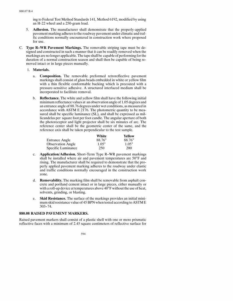
594
880.07 B.4
ing to Federal Test Method Standards 141, Method 6192, modified by usingan H-22 wheel and a 250-gram load.
5. Adhesion. The manufacturer shall demonstrate that the properly-appliedpavementmarking adheres to the roadwaypavement under climatic and traf-fic conditions normally encountered in construction work where proposedfor use.
C. Type R--WR Pavement Markings. The removable striping tape must be de-signed and constructed in such a manner that it can be readily removed when themarkingsareno longer applicable.The tape shall be capableofperforming for theduration of a normal construction season and shall then be capable of being re-moved intact or in large pieces manually.
1. Materials.
a. Composition. The removable preformed retroreflective pavementmarkings shall consist of glass beads embedded in white or yellow filmwith a thin flexible conformable backing which is precoated with apressure-sensitive adhesive. A structured interlaced medium shall beincorporated to facilitate removal.
b. Reflectance. The white and yellow film shall have the following initialminimumreflectance values at anobservation angle of 1.05degrees andan entrance angle of 88.76 degrees underwet conditions, asmeasured inaccordance with ASTM E 2176. The photometric quantity to be mea-sured shall be specific luminance (SL), and shall be expressed as mil-licandelas per square foot per foot candle. The angular aperture of boththe photoreceptor and light projector shall be six minutes of arc. Thereference center shall be the geometric center of the same, and thereference axis shall be taken perpendicular to the test sample.
White YellowEntrance Angle 88.76° 88.76°Observation Angle 1.05° 1.05°Specific Luminance 250 200
c. Application/Adhesion. Short-Term Type R--WR pavement markingsshall be installed where air and pavement temperatures are 50°F andrising. The manufacturer shall be required to demonstrate that the pro-perly applied pavement marking adheres to the roadway under elasticand traffic conditions normally encouraged in the construction workzone.
d. Removability. The marking film shall be removable from asphalt con-crete and portland cement intact or in large pieces, either manually orwith a roll-up device at temperatures above 40°Fwithout the use of heat,solvents, grinding, or blasting.
e. Skid Resistance. The surface of the markings provides an initial mini-mumskid resistance value of 45BPNwhen tested according toASTME303--74.
880.08 RAISED PAVEMENT MARKERS.
Raised pavement markers shall consist of a plastic shell with one or more prismaticreflective faces with a minimum of 2.45 square centimeters of reflective surface for

595
880.09 B.3
each direction required to reflect incident light. The marker shall be fitted with pres-sure-sensitive adhesive for application to a primed surface.
Thematerials used shall be capable of being easily applied and removed.TheContrac-tor shall demonstrate that the properly-applied pavementmarking adheres to the road-way under climatic and traffic conditions normally encountered in the constructionwork zone.
880.09 EPOXY PAINT PAVEMENT MARKING.
A. General. This Specification provides for the classification of epoxy resin pave-ment marking systems by type. Type II shall be used unless Type I is specified onthe plans.
1. Type I
A fast curematerial suitable for line applications and, under ideal conditions,may not require coning.
2. Type II
A slow cure material suitable for all applications of pavement markings un-der controlled traffic conditions, i.e., coning is required and flaggingmay beas directed by the Engineer.
B. Epoxy Resin Material.
1. General.Thematerial shall be composed of epoxy resins and pigments only.No solvents are to be given off to the environment upon application to apavement surface. Type II material shall be completely free of TMPTA (Tri-Methyl Propane Tri-Acrylate) and other multi-functional monomers.
2. Color. The color of the white epoxy shall be a pure flat white, free of tints.The color of the yellow epoxy shall closely match Color Number 33538 ofFederal Standard 595 and shall conform to the following CIE Chromaticitylimits using illuminant “C”:
x | 0.470 | 0.485 | 0.520 | 0.480y | 0.440 | 0.460 | 0.450 | 0.420
Daylight Directional Reflectance (Y), white, minimum 83Daylight Directional Reflectance (Y), yellow, minimum 50
Testing will be according to:
Daylight Directional Reflectance ASTM D 2805Color ASTM D 2805
3. Adhesion Capabilities.When the adhesion of the material to portland ce-ment concrete (the concrete shall have aminimumof 300psi tensile strength)is tested according to American Concrete Institute Committee 503 testingprocedure, the failure of the system must take place in the concrete. Thelaboratory concrete test specimen shall be 90_Fwhen thematerial is applied,after which the material shall be allowed to cure for 72 hours at 732_F.

596
880.09 B.4
4. Abrasion Resistance.When the abrasion resistance of thematerial is testedaccording to ASTMC 501 with a CS-17 wheel under a load of 1,000 gramsfor 1,000 cycles, thewear index shall be nogreater than 100. (Thewear indexis theweight inmilligrams that is abraded from the sample under the test con-ditions).
5. Hardness. The Type D durometer hardness of the material shall be not lessthan 75 nor more than 90 when tested according to ASTMD 2240 after thematerial has cured for 72 hours at 732_F.
6. Tensile Strength.The tensile strength of thematerial,when tested accordingto ASTM D 638, shall not be less than 4,500 psi after 72 hours cure time at732_F.
7. Compressive Strength. The compressive strength of the material, whentested according to ASTM D 695, shall not be less than 12,000 psi after 72hours cure time at 732_F.
8. Shelf Life. The individual components shall not require mixing prior to usewhen stored for a period of 12 months.
9. Yellowness Index.
ASTM D 1925 Max before QUV 10. . . . . . . . . . . . . . . . . . . . . .Max after QUV 30
10. Laboratory No-Pick-Up Time. The material shall have a no-pick-up timebetween 10 and 45 minutes. The no-pick-up time shall be tested in accor-dance with ASTMD711, with the material prepared according to themanu-facturer’s instructions and applied at a 20mil wet film thickness at 73° ± 2°Fwith the proper application of glass beads.
C. GlassBeads.GlassBeads shallmeet the requirementsofAASHTOM247TypeI, have a roundness of at least 80 percent, and shall be moisture treated. The glassbeads shall be applied at a rate of at least 25 lb/gal.
D. SamplingRate andProcedures.One pint samples of eachmanufacturer’s lot orbatch furnished for the contract shall be submitted at least 15daysprior touse. Allsamplesmustbe submitted to theDepartment’sMaterials andResearchLaboratory.Samples shall be identified as follows:
1. Manufacturer’s name.
2. Manufacturer’s product number.
3. Lot/Batch number.
4. Color.
5. Intended state project numbers.
6. Date manufactured.

597
894.01 B.2
E. PackagingofEpoxyComponentsandGlassBeads.Containers for epoxycom-ponents shall be marked with the manufacturer’s name, product identificationnumber, lot or batch number, date of manufacture, color, net weight of contents.Containers for glass beads shall be marked with the name of manufacturer, thewording “Glass Beads,” lot or batch number, coating type, date manufactured,and the net weight.
SECTION 894HIGHWAY SIGNS AND POSTS
894.01 SIGN BACKINGMATERIAL.
A. Materials.
1. Flat Sheet Aluminum. Flat sheet aluminum shall be an alloy meetingASTM B 209 Alloy 6061 T6, or 5052-H38 with mill finish.
2. Extruded Aluminum Panels. Extruded Aluminum Panels shall meetASTM B 221 Alloy 6063 T6. The panels shall be furnished in 12-inch and6-inch sections as shown on the Plans. All panels shall be flat and straightwithin commercial tolerances established by the aluminum industry.
B. Shop Surface Preparation and Processing.All sign backing shall be clean andfree of rust, white rust, oil, and dirt. The holes shall be shop drilled to the sizes andat locations shown in the Contract. Holes required in the sign backing shall not befield drilled.
1. Degreasing. The extruded aluminum panels shall be rubbed with a cleanwhite cloth after degreasing and if any stickymaterial shows up on the cloth,the panels shall be degreased again. All aluminum sign backing shall be de-greased by one of the following methods:
a. Vapor Degreasing. Aluminum materials shall be immersed in a satu-rated vapor of Trichlorethylene. Trademark printing shall be removedwith a lacquer thinner or a controlled alkaline cleaning system.
b. Alkaline Degreasing. The aluminum shall be immersed in an alkalinesolution controlled and titrated according to the solutionmanufacturer’srecommendations. The immersion time shall be dependent upon thegauge of the metal and the amount of soil to be removed.
2. Etching.All sheet aluminum shall be etched after degreasing. Extruded alu-minum panels which have a roughened surface texture suitable for paint orsheeting shall not be etched after degreasing unless the Engineer determinesthe panels are unsuitable. Etching shall be performed by one of the followingmethods:
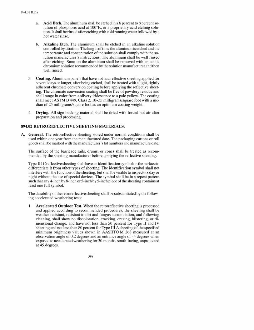
598
894.01 B.2.a
a. Acid Etch.The aluminum shall be etched in a 6 percent to 8 percent so-lution of phosphoric acid at 100°F., or a proprietary acid etching solu-tion. It shall be rinsedafter etchingwithcold runningwater followedbyahot water rinse.
b. Alkaline Etch. The aluminum shall be etched in an alkaline solutioncontrolledby titration.The lengthof time the aluminumis etchedand thetemperature and concentration of the solution shall comply with the so-lution manufacturer’s instructions. The aluminum shall be well rinsedafter etching. Smut on the aluminum shall be removed with an acidicchromiumsolution recommendedby the solutionmanufacturer and thenwell rinsed.
3. Coating.Aluminum panels that have not had reflective sheeting applied forseveral days or longer, after being etched, shall be treatedwith a light, tightlyadherent chromate conversion coating before applying the reflective sheet-ing. The chromate conversion coating shall be free of powdery residue andshall range in color from a silvery iridescence to a pale yellow. The coatingshall meet ASTM B 449, Class 2, 10--35 milligrams/square foot with a me-dian of 25 milligrams/square foot as an optimum coating weight.
4. Drying. All sign backing material shall be dried with forced hot air afterpreparation and processing.
894.02 RETROREFLECTIVE SHEETINGMATERIALS.
A. General. The retroreflective sheeting stored under normal conditions shall beused within one year from the manufactured date. The packaging cartons or rollgoods shall bemarkedwith themanufacturer’s lot numbersandmanufacturedate.
The surface of the barricade rails, drums, or cones shall be treated as recom-mended by the sheeting manufacturer before applying the reflective sheeting.
Type III C reflective sheeting shall havean identification symbolon the surface todifferentiate it from other types of sheeting. The identification symbol shall notinterferewith the function of the sheeting, but shall be visible to inspectors day ornight without the use of special devices. The symbol shall be in a repeat patternsuch that any4-inchby8-inchor 5-inchby5-inch piece of the sheeting contains atleast one full symbol.
The durability of the retroreflective sheeting shall be substantiated by the follow-ing accelerated weathering tests:
1. Accelerated Outdoor Test.When the retroreflective sheeting is processedand applied according to recommended procedures, the sheeting shall beweather-resistant, resistant to dirt and fungus accumulation, and followingcleaning, shall show no discoloration, cracking, crazing, blistering, or di-mensional change, and have not less than 50 percent for Type II and IVsheeting and not less than 80 percent for Type III A sheeting of the specifiedminimum brightness values shown in AASHTO M 268 measured at anobservation angle of 0.2 degrees and an entrance angle of --4 degrees whenexposed to acceleratedweathering for 30 months, south-facing, unprotectedat 45 degrees.

599
894.02 B
2. Accelerated Machine Test. The retroreflective sheeting shall meet the arti-ficial weathering requirements of AASHTO M268measured at an observa-tion angle of 0.2 degrees and an entrance angle of --4 degrees.
The Contractor shall furnish written evidence showing conformance with one ofthe following:
1. The accelerated outdoor test, done in North Dakota or in a state located atlower latitudes, or
2. The acceleratedmachine test and three years of performance in the fieldwithno problems.
The Contractor shall secure from the manufacturer all warranties and guaranteeswith respect tomaterials, parts,workmanship, or performancewhich theproductscovered by the proposal bear, and include these warranties and guarantees withthe certification.
B. Type II and III A Retroreflective Sheeting Material. Type II and III Aretroreflective sheeting shall meet AASHTO M 268 and the following:
Processed retroreflective sheeting shall be applied to approved sign basema-terial and cleaned according to manufacturer’s recommendations for use ontraffic control signs. TheContractor shall furnish awritten assurance that thesheeting will meet the requirements of the following tables throughout thesatisfactory performance life and be effective for its intended purpose whenviewed from a vehicle.
TYPE II RETROREFLECTIVE SHEETING
Average MinimumCandelas per FootCandle per sq. ft. at Satisfactory
Sheeting Type 0.2° divergence and Performanceand Color --4° incidence* Life
Silver-White #1 30.0 5 yearsSilver-White #2 36.0 5 yearsYellow 20.0 5 yearsRed 5.0 5 yearsBlue 2.0 5 yearsGreen 3.0 5 yearsOrange 10.0 5 yearsBrown 0.4 5 years
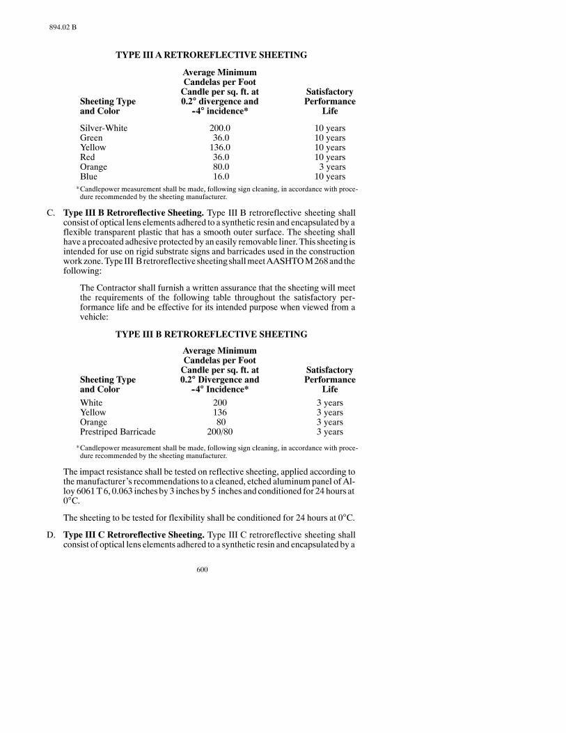
600
894.02 B
TYPE III ARETROREFLECTIVE SHEETING
Average MinimumCandelas per FootCandle per sq. ft. at Satisfactory
Sheeting Type 0.2° divergence and Performanceand Color --4° incidence* Life
Silver-White 200.0 10 yearsGreen 36.0 10 yearsYellow 136.0 10 yearsRed 36.0 10 yearsOrange 80.0 3 yearsBlue 16.0 10 years*Candlepower measurement shall be made, following sign cleaning, in accordance with proce-dure recommended by the sheeting manufacturer.
C. Type III B Retroreflective Sheeting. Type III B retroreflective sheeting shallconsist of optical lens elements adhered to a synthetic resin and encapsulated by aflexible transparent plastic that has a smooth outer surface. The sheeting shallhave a precoated adhesive protected by an easily removable liner. This sheeting isintended for use on rigid substrate signs and barricades used in the constructionworkzone.Type III B retroreflective sheetingshallmeetAASHTOM268and thefollowing:
The Contractor shall furnish a written assurance that the sheeting will meetthe requirements of the following table throughout the satisfactory per-formance life and be effective for its intended purpose when viewed from avehicle:
TYPE III B RETROREFLECTIVE SHEETING
Average MinimumCandelas per FootCandle per sq. ft. at Satisfactory
Sheeting Type 0.2° Divergence and Performanceand Color --4° Incidence* Life
White 200 3 yearsYellow 136 3 yearsOrange 80 3 yearsPrestriped Barricade 200/80 3 years
*Candlepower measurement shall be made, following sign cleaning, in accordance with proce-dure recommended by the sheeting manufacturer.
The impact resistance shall be tested on reflective sheeting, applied according tothemanufacturer’s recommendations to a cleaned, etched aluminumpanel of Al-loy 6061T6, 0.063 inches by 3 inches by5 inches and conditioned for 24 hours at0°C.
The sheeting to be tested for flexibility shall be conditioned for 24 hours at 0°C.
D. Type III C Retroreflective Sheeting. Type III C retroreflective sheeting shallconsist of optical lens elements adhered to a synthetic resin and encapsulated by a

601
894.02 E.2
flexible transparent plastic that has a smooth outer surface. The sheeting shallhave a precoated adhesive protected by an easily removable liner. This sheeting isintended for useonplastic reboundabledevices suchasdrumsand flexibledeline-ation posts. Type III C retroreflective sheeting shall meet the weathering require-ments of AASHTO M 268, Type IV and the following:
The Contractor shall furnish a written assurance that the sheeting will meetthe requirement of the following table and be effective for its intended pur-pose when viewed from a vehicle.
TYPE III C RETROREFLECTIVE SHEETING
Average minimum Candeles per foot candle per square foot.
Observation EntranceAngle Angle White Yellow Orange
0.2° --4° 250 170 1000.2° +30° 150 100 600.5° --4° 95 62 300.5° +30° 65 45 25
The impact-resistant aluminum panel shall be the same as Type III B reflectivesheeting.
The impact resistance shall be testedonaGardnerVariable ImpactTester, I6-1120using a four-pound weight with a 5/8-inch rounded tip dropped from a 100 inch-pound setting.
Type IIIC reflective sheetingperformanceon reboundableplastic substrates shallbe measured using the following test:
The device shall be impacted three times by a 4,000-pound vehicle, with a20-inch bumper, at 40mph. Each impact shall be a direct hit (glancing blowswill not be allowed). After the impacts, the reflective sheeting shall be con-sidered performing satisfactorilywhenno loss of sheeting results and there isnovisible change indayandnightperformance (whenviewedfrom500feet).
The sheeting to be tested for flexibility shall be conditioned for 24 hours at 0°C.
E. Type IV Reflective Sheeting. The Type IV reflective sheeting shall consist ofhigh-gloss transparent ultraviolet light-stabilized polyester filmbonded to a layerof polyester cube corner prisms with not less than 40,000 prisms per square inchmeeting AASHTO M 268 and the following:
1. Type IV, Class 1 Reflective Sheeting. The backing for the polyester sheet-ing used on barricade rails, drums, and traffic cones shall be an opaque-whiteplasticized polyester film not less than 0.004 inch thick with an adhesivebacking meeting AASHTO M 268, Class 1.
2. FlexibleRollupSign,Non-AdhesiveBackingFabric.Thepolyester sheet-ing on the flexible rollup portable signs shall be coated on both sideswith or-ange pigment polyester and shall meet the following Specifications:
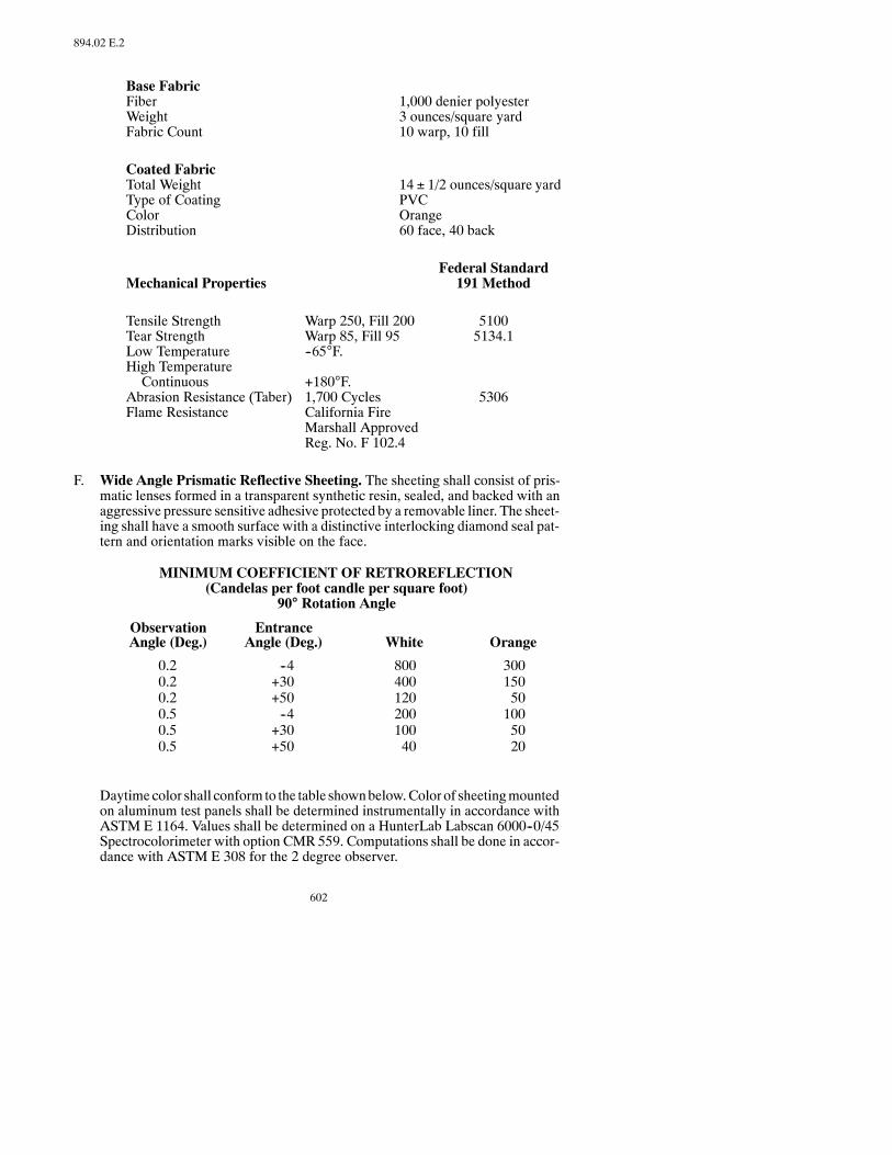
602
894.02 E.2
Base FabricFiber 1,000 denier polyesterWeight 3 ounces/square yardFabric Count 10 warp, 10 fill
Coated FabricTotal Weight 14 ± 1/2 ounces/square yardType of Coating PVCColor OrangeDistribution 60 face, 40 back
Federal StandardMechanical Properties 191 Method
Tensile Strength Warp 250, Fill 200 5100Tear Strength Warp 85, Fill 95 5134.1Low Temperature --65°F.High TemperatureContinuous +180°F.
Abrasion Resistance (Taber) 1,700 Cycles 5306Flame Resistance California Fire
Marshall ApprovedReg. No. F 102.4
F. Wide Angle Prismatic Reflective Sheeting. The sheeting shall consist of pris-matic lenses formed in a transparent synthetic resin, sealed, and backed with anaggressive pressure sensitive adhesive protected by a removable liner. The sheet-ing shall have a smooth surface with a distinctive interlocking diamond seal pat-tern and orientation marks visible on the face.
MINIMUM COEFFICIENT OF RETROREFLECTION(Candelas per foot candle per square foot)
90° Rotation Angle
ObservationAngle (Deg.)
EntranceAngle (Deg.) White Orange
0.20.20.20.50.50.5
--4+30+50--4+30+50
80040012020010040
300150501005020
Daytimecolor shall conform to the table shownbelow.Color of sheetingmountedon aluminum test panels shall be determined instrumentally in accordance withASTM E 1164. Values shall be determined on a HunterLab Labscan 6000--0/45Spectrocolorimeter with option CMR 559. Computations shall be done in accor-dance with ASTM E 308 for the 2 degree observer.

603
894.02 G
COLOR SPECIFICATION LIMITS* (DAYTIME)ReflectanceLimit Y (%)
Color
White
Orange
x
0.303
0.558
y
0.300
0.352
x
0.368
0.636
y
0.366
0.364
x
0.340
0.570
y
0.393
0.429
x
0.274
0.506
y
0.329
0.404
min.
40
12
max.
--
30
1 2 3 4
*The four pairs of chromaticity coordinates determine the acceptable color in terms of the CIE 1931 stan-dard colorimetric system measured with standard illuminant D65.
The sheeting shall show no cracking outside the impact area when the face of thepanel is subjected to an impact of 100 inch-pounds, using aweightwith a 5/8 inchdiameter rounded tip dropped from a height necessary to generate an impact of100 inch-pounds, at temperatures of both 32°F. and 72°F.
The impact-resistant aluminum panel shall be the same as required for Type III Breflective sheeting.
The Retroreflective Sheeting shall be processed and applied to aluminum signblankmaterials in accordance with the sheetingmanufacturer’s instructions. Thesheeting shall perform effectively for three years. If, within three years from thedateof acceptance, the sheetinghasdeteriorateddue tonatural causes to theextentthat (1) the sign is ineffective for its intendedpurposewhenviewed fromamovingvehicle under normal day or night driving conditions by a driver with normal vi-sion; or (2) the coefficient of retroreflection, after cleaning, is less than 400 forwhite and 150 for orange when measured at 0.2 degrees observation and --4degrees entrance at 90 degrees rotation; new sheeting will be furnished andinstalled by the Contractor.
G. Fluorescent Orange Wide Angle Prismatic Retroreflective Sheeting. Thesheeting shall consist of prismatic lenses formed in a transparent fluorescentorange synthetic resin, sealed, and backed with an aggressive pressure sensitiveadhesive protectedby a removable liner. The sheeting shall have a smooth surfacewith distinctive interlocking diamond seal pattern and orientation marks visiblefrom the face.
MINIMUM COEFFICIENT OF RETROREFLECTION(Candelas per foot candle per square foot)
90° Rotation Angle
ObservationAngle (Deg.)
EntranceAngle (Deg.) Orange
0.20.20.20.50.50.5
--4+30+50--4+30+50
20012050805020
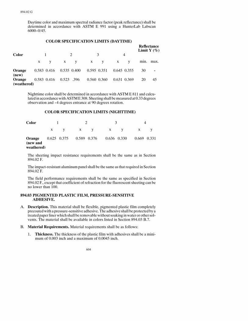
604
894.02 G
Daytime color and maximum spectral radiance factor (peak reflectance) shall bedetermined in accordance with ASTM E 991 using a HunterLab Labscan6000--0/45.
COLOR SPECIFICATION LIMITS (DAYTIME)ReflectanceLimit Y (%)
Color
Orange(new)Orange(weathered)
x
0.583
0.583
y
0.416
0.416
x
0.535
0.523
y
0.400
.396
x
0.595
0.560
y
0.351
0.360
x
0.645
0.631
y
0.355
0.369
min.
30
20
max.
--
45
1 2 3 4
Nighttime color shall be determined in accordance with ASTME 811 and calcu-lated in accordancewithASTME308.Sheeting shall bemeasuredat 0.33degreesobservation and --4 degrees entrance at 90 degrees rotation.
COLOR SPECIFICATION LIMITS (NIGHTTIME)
Color
Orange(new andweathered)
x
0.625
y
0.375
x
0.589
y
0.376
x
0.636
y
0.330
x
0.669
y
0.331
1 2 3 4
The sheeting impact resistance requirements shall be the same as in Section894.02 F.
The impact-resistant aluminumpanel shall be the same as that required in Section894.02 F.
The field performance requirements shall be the same as specified in Section894.02 F., except that coefficient of refraction for the fluorescent sheeting can beno lower than 100.
894.03 PIGMENTED PLASTIC FILM, PRESSURE-SENSITIVEADHESIVE.
A. Description. This material shall be flexible, pigmented plastic film completelyprecoatedwith apressure-sensitive adhesive.The adhesive shall beprotectedbyatreatedpaper linerwhich shall be removablewithout soaking inwater or other sol-vents. The material shall be available in colors listed in Section 894.03 B.7.
B. Material Requirements.Material requirements shall be as follows:
1. Thickness. The thickness of the plastic film with adhesives shall be a mini-mum of 0.003 inch and a maximum of 0.0045 inch.

605
894.03 B.9
2. Film.Theunapplied and applied film shall be readily processed and shall en-sure adequate adhesion with process or printed inks recommended by themanufacturer.
3. Flexibility. The material shall be sufficiently flexible to permit applicationover and conformance to moderately-contoured surfaces.
4. Gloss. The film shall have a minimum initial 60 degree gloss value of 35when tested according to ASTMD 523, measuring at least three portions ofthe film to obtain uniformity.
5. Adhesive. The precoated adhesive shall form a durable bond to smooth,clean, corrosion-resistant, andweather-resistant surface; shall be of uniformthickness; shall be noncorrosive to applied surfaces; and shall have no stain-ing effect on the film. The adhesive shall adhere securely at temperatures of--30°F. to +200°F.; shall not crack, chip, or peel voluntarily; nor shall it be re-moved from the panel in one piece without the aid of a tool.
6. Sunlight Resistance. There shall be no effect on the adhesive tack or per-formance following exposure of the adhesive face under a newGeneralElec-tric RS Sunlamp for a period of six hours at a distance of 8 inches.
7. Exterior Exposure. The unprocessed material shall withstand the years ofexposure, listed below by color, in a vertical, south facing exterior exposureinTexas.During the exposure, theunprocessedmaterial shall shownoappre-ciable discoloration, cracking, crazing, blistering, delamination, or loss ofadhesion. A slight amount of chalking is permissible. The Contractor shallfurnish awritten assurance from themanufacturer that the sheetingwillmeetthe requirements of the following table and be effective for its intended pur-pose when viewed from a vehicle, throughout the satisfactory performancelife:
SatisfactoryPerformance
Color Life
White 7 yearsBlack 7 yearsYellow 5 yearsAluminum 5 yearsInsignia Blue 5 yearsTransparent 5 yearsRed 3 yearsGold 3 years
TheContractor shall secure fromthemanufacturer allwarranties andguaran-teeswith respect tomaterials, parts,workmanship, or performancewhich theproductscoveredby theproposalbear, and include thesewarranties andguar-antees with the certification.
8. Fungus Growth. The film shall not support fungus growth.
9. Plastic Lettering.Plastic lettering filmas furnished in rolls, sheets, or lettersshall be free from ragged edges, cracks, blisters, streaks, foreign matter, or
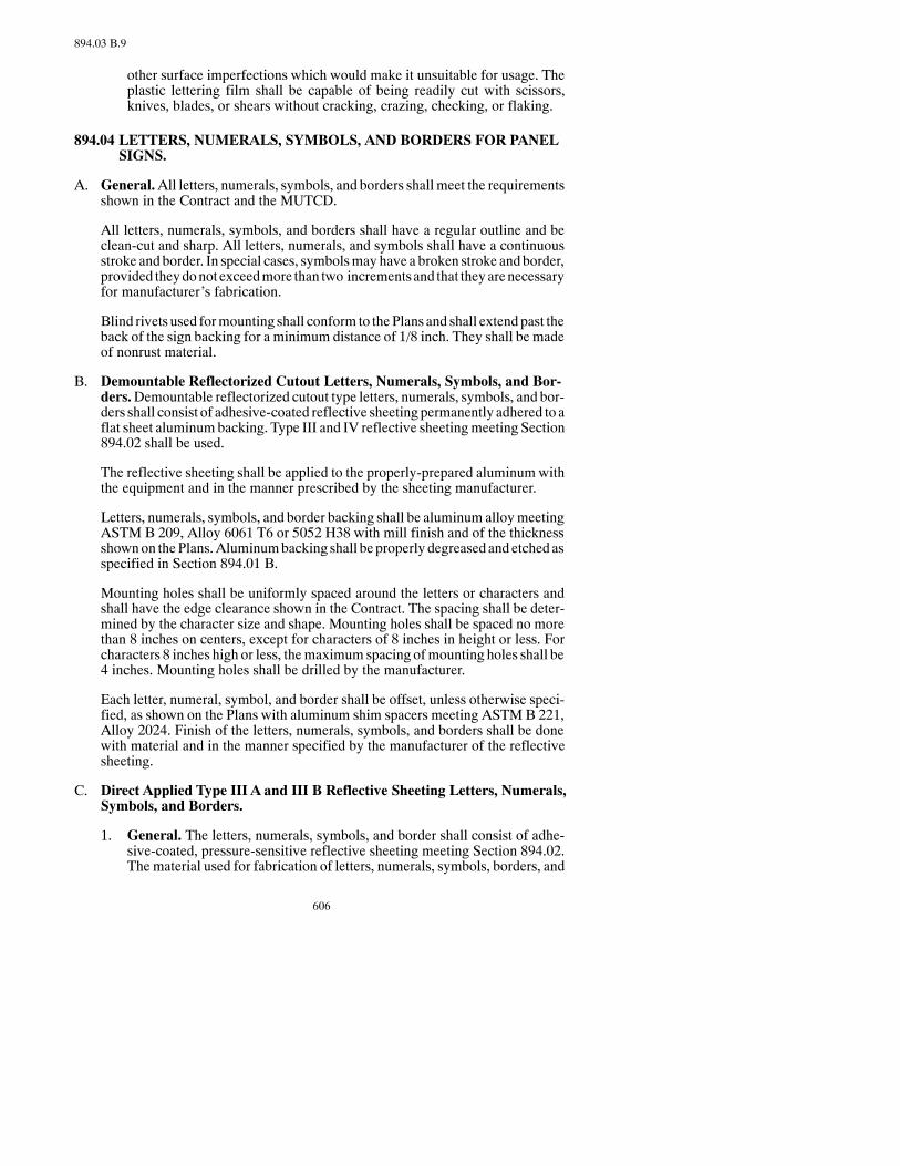
606
894.03 B.9
other surface imperfections which would make it unsuitable for usage. Theplastic lettering film shall be capable of being readily cut with scissors,knives, blades, or shears without cracking, crazing, checking, or flaking.
894.04 LETTERS, NUMERALS, SYMBOLS, AND BORDERS FOR PANELSIGNS.
A. General.All letters, numerals, symbols, and borders shall meet the requirementsshown in the Contract and the MUTCD.
All letters, numerals, symbols, and borders shall have a regular outline and beclean-cut and sharp. All letters, numerals, and symbols shall have a continuousstroke and border. In special cases, symbolsmay have a broken stroke andborder,provided theydonotexceedmore than two incrementsand that theyarenecessaryfor manufacturer’s fabrication.
Blind rivets used formounting shall conform to thePlans and shall extend past theback of the sign backing for a minimum distance of 1/8 inch. They shall be madeof nonrust material.
B. Demountable Reflectorized Cutout Letters, Numerals, Symbols, and Bor-ders.Demountable reflectorized cutout type letters, numerals, symbols, and bor-ders shall consist of adhesive-coated reflective sheeting permanently adhered to aflat sheet aluminumbacking. Type III and IV reflective sheetingmeeting Section894.02 shall be used.
The reflective sheeting shall be applied to the properly-prepared aluminumwiththe equipment and in the manner prescribed by the sheeting manufacturer.
Letters, numerals, symbols, and border backing shall be aluminum alloymeetingASTM B 209, Alloy 6061 T6 or 5052 H38 with mill finish and of the thicknessshownon thePlans.Aluminumbacking shall beproperly degreasedand etchedasspecified in Section 894.01 B.
Mounting holes shall be uniformly spaced around the letters or characters andshall have the edge clearance shown in the Contract. The spacing shall be deter-mined by the character size and shape. Mounting holes shall be spaced no morethan 8 inches on centers, except for characters of 8 inches in height or less. Forcharacters 8 inches high or less, themaximum spacing ofmounting holes shall be4 inches. Mounting holes shall be drilled by the manufacturer.
Each letter, numeral, symbol, and border shall be offset, unless otherwise speci-fied, as shown on the Plans with aluminum shim spacers meeting ASTMB 221,Alloy 2024. Finish of the letters, numerals, symbols, and borders shall be donewith material and in the manner specified by the manufacturer of the reflectivesheeting.
C. Direct Applied Type III A and III B Reflective Sheeting Letters, Numerals,Symbols, and Borders.
1. General. The letters, numerals, symbols, and border shall consist of adhe-sive-coated, pressure-sensitive reflective sheeting meeting Section 894.02.The material used for fabrication of letters, numerals, symbols, borders, and

607
894.05 A.3
routemarkers shall be sampledand testedas specified for other reflectivema-terials.
2. Fabrication. Letters, numerals, symbols, and borders shall be cut fromreflective sheeting and shall have smooth regular outline, free from raggedortorn edges.Letters, numerals, and symbolshaving interior or exterior cornersshall have these corners cut with a smooth 3/16 inch ± 1/16 inch radius.Border corners and strips shall have no corner radius. Routemarkers used inconjunction with direct-applied letter shall be applied to 0.040 aluminumbacking and shall be attached with blind rivets or other common nonrustfasteners. Fasteners shall be placed amaximumof 6 inches on center aroundthe perimeter of the shield. The reflective sheeting shall be of the same typespecified for the letters. All sheeting, numerals, symbols, and borders shallshow careful workmanship and shall be of regular outline.
894.05 POSTS AND HARDWARE FOR SIGNS.
A. Hardware for Signs.
1. General.All aluminum bolts, nuts, U-bolts, lockwashers, and washers shallbe given at least a 0.002-inch anodic coating and chromate seal. All steelbolts, nuts,U-bolts, lockwashers, andwashers shall begalvanized steelmeet-ing ASTM A 153.
Use of substitute alloys in lieu of the alloy specified for various items of“Hardware for Signs”may be approved by the Engineer upon submission ofdocumented evidence that the proposed substitute alloy has applicable quali-ties equal to or superior to the designated alloy.
2. Bolts. Aluminum panel bolts, etc., shall be fabricated of aluminum alloymeeting ASTM B 211, Alloy 2024 T4 or 6061 T6.
Steel panel bolts, machine bolts, etc., shall meet ASTM A 307.
3. Nuts. Aluminum nuts, hex nuts, vandal-resistant nuts shall be fabricated ofaluminum alloy meeting ASTM B 211, Alloy 6061 T6.
Steel hex nuts shall meet ASTM A 307.
In lieu of using torquewrenches to obtain the required torques for fuse jointsand slip base used in the breakaway system, the Torque Control Nut Systemmay be used. This system shall provide automatic torque control, consis-tently-controlled preload, vibration resistance, high strength, easy installa-tion, simple inspection, and resistance to weather effects.
The torque control nut shall be designed tomate with standard high-strengthbolts meeting ASTMA 325. The minimum stripping strength of the threadsshall be equal to or shall exceed the strength level of the mating bolts.
The self-locking quality of resistance to loosening shallmeet the tests in Fed-eral SpecificationMILN25027 and shall be installed according to themanu-facturer’s recommendations.

608
894.05 A.4
4. Washers. Aluminum lockwashers shall be fabricated of aluminum alloymeeting ASTM B 209, Alloy 7075 T6.
Aluminum flat washers shall be fabricated of aluminum alloy meetingASTM B 209, Alloy 2024 T4.
Steel lockwashers shall be fabricated of steel meeting ANSI B 27.1.
Steel flat washers shall be fabricated of steel meeting ASTM A 307.
Plastic washers shall be fabricated to the sheeting manufacturer’s specifica-tions.
5. Stringers. Aluminum stringers shall be fabricated to Plan dimensions andmade of aluminum alloy meeting ASTMB 221, Alloy 6061 T6 or ASTMB308, Alloy 6061 T6.
Steel stringers shall be fabricated to Plan dimensions andmade of steelmeet-ing ASTM A 36.
6. AluminumAlloy Castings. Brackets, post caps, and fuse plates may beeither permanent mold castings or sand castings.
Aluminum alloy permanent mold castings shall meet ASTM B 108, AlloySG70A F or SG80A T6.
Aluminum alloy sand castings shall meet ASTM B 26, Alloy SG70A F orSG70A T6.
7. Steel Castings.Brackets, post caps, and fuse plates shall meet AASHTOM103, Grade 65-35.
8. U-Bolts. Aluminum U-bolts shall be fabricated of aluminum alloy meetingASTM B 211, Alloy 2017 T4.
Steel U-bolts shall be fabricated of steel meeting ASTM A 307.
9. Anchor Bolts.Anchor bolts, anchor studs, nuts, and washers shall be fabri-catedof steelmeetingASTMA307andmeetAASHTOM314Grade55Me-chanical requirements.
All nuts, washers, and anchor studs shall be galvanized steel meetingASTMA 153.
The hex bar shall be tappedwithU.S.S. Standard right thread, both ends, andmade of steel meeting ASTM A 307.
10. Attachment Clip and Plate. Attachment clip and plate for attachment ofsteel panels shall be fabricated as shown in the Contract, and made of steelmeeting ASTM A 283 and galvanized in conformance to ASTM A 153.
11. Fuse Joint Bolts.Aluminumfuse plate bolts andwashers shall be fabricatedfrom aluminum meeting ASTM B 211, Alloy 2024 T4.
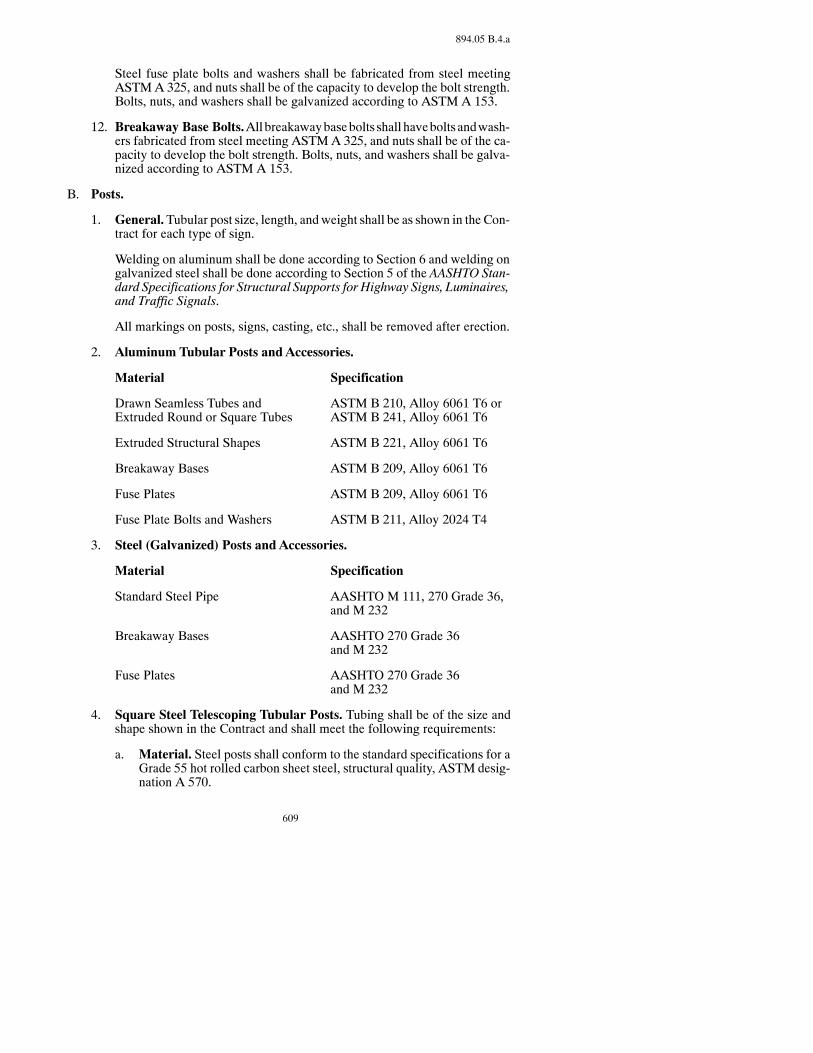
609
894.05 B.4.a
Steel fuse plate bolts and washers shall be fabricated from steel meetingASTMA 325, and nuts shall be of the capacity to develop the bolt strength.Bolts, nuts, and washers shall be galvanized according to ASTM A 153.
12. Breakaway Base Bolts.Allbreakawaybasebolts shall havebolts andwash-ers fabricated from steel meeting ASTMA 325, and nuts shall be of the ca-pacity to develop the bolt strength. Bolts, nuts, and washers shall be galva-nized according to ASTM A 153.
B. Posts.
1. General.Tubular post size, length, andweight shall be as shown in the Con-tract for each type of sign.
Welding on aluminum shall be done according to Section 6 and welding ongalvanized steel shall be done according to Section 5 of the AASHTO Stan-dard Specifications for Structural Supports for Highway Signs, Luminaires,and Traffic Signals.
All markings on posts, signs, casting, etc., shall be removed after erection.
2. Aluminum Tubular Posts and Accessories.
Material Specification
Drawn Seamless Tubes and ASTM B 210, Alloy 6061 T6 orExtruded Round or Square Tubes ASTM B 241, Alloy 6061 T6
Extruded Structural Shapes ASTM B 221, Alloy 6061 T6
Breakaway Bases ASTM B 209, Alloy 6061 T6
Fuse Plates ASTM B 209, Alloy 6061 T6
Fuse Plate Bolts and Washers ASTM B 211, Alloy 2024 T4
3. Steel (Galvanized) Posts and Accessories.
Material Specification
Standard Steel Pipe AASHTO M 111, 270 Grade 36,and M 232
Breakaway Bases AASHTO 270 Grade 36and M 232
Fuse Plates AASHTO 270 Grade 36and M 232
4. Square Steel Telescoping Tubular Posts. Tubing shall be of the size andshape shown in the Contract and shall meet the following requirements:
a. Material. Steel posts shall conform to the standard specifications for aGrade 55 hot rolled carbon sheet steel, structural quality, ASTM desig-nation A 570.
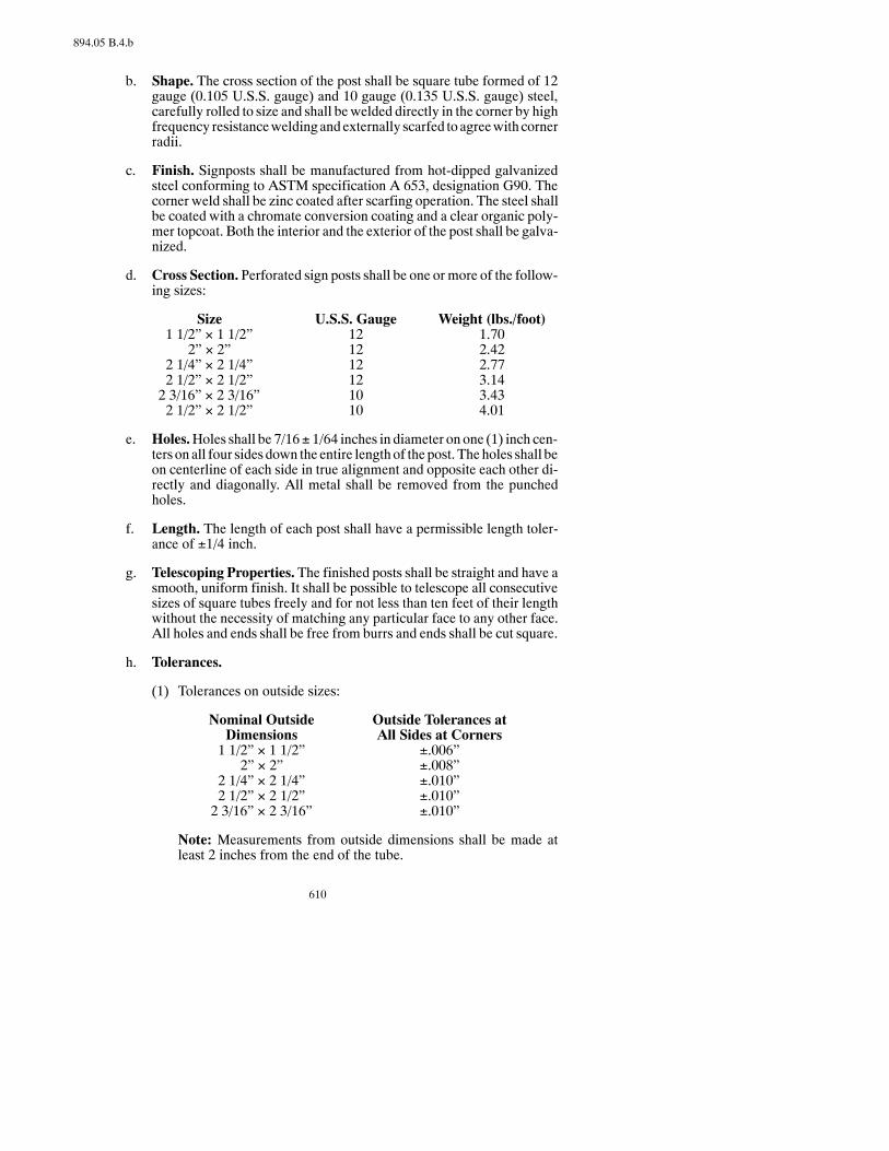
610
894.05 B.4.b
b. Shape. The cross section of the post shall be square tube formed of 12gauge (0.105 U.S.S. gauge) and 10 gauge (0.135 U.S.S. gauge) steel,carefully rolled to size and shall bewelded directly in the corner by highfrequency resistanceweldingandexternally scarfed toagreewithcornerradii.
c. Finish. Signposts shall be manufactured from hot-dipped galvanizedsteel conforming to ASTM specification A 653, designation G90. Thecorner weld shall be zinc coated after scarfing operation. The steel shallbe coated with a chromate conversion coating and a clear organic poly-mer topcoat. Both the interior and the exterior of the post shall be galva-nized.
d. Cross Section. Perforated sign posts shall be one or more of the follow-ing sizes:
Size U.S.S. Gauge Weight (lbs./foot)1 1/2” × 1 1/2” 12 1.70
2” × 2” 12 2.422 1/4” × 2 1/4” 12 2.772 1/2” × 2 1/2” 12 3.142 3/16” × 2 3/16” 10 3.432 1/2” × 2 1/2” 10 4.01
e. Holes.Holes shall be 7/16± 1/64 inches in diameter on one (1) inch cen-ters on all four sides down the entire lengthof the post. Theholes shall beon centerline of each side in true alignment and opposite each other di-rectly and diagonally. All metal shall be removed from the punchedholes.
f. Length. The length of each post shall have a permissible length toler-ance of ±1/4 inch.
g. Telescoping Properties. The finished posts shall be straight and have asmooth, uniform finish. It shall be possible to telescope all consecutivesizes of square tubes freely and for not less than ten feet of their lengthwithout the necessity of matching any particular face to any other face.All holes and ends shall be free from burrs and ends shall be cut square.
h. Tolerances.
(1) Tolerances on outside sizes:
Nominal Outside Outside Tolerances atDimensions All Sides at Corners1 1/2” × 1 1/2” ±.006”
2” × 2” ±.008”2 1/4” × 2 1/4” ±.010”2 1/2” × 2 1/2” ±.010”2 3/16” × 2 3/16” ±.010”
Note: Measurements from outside dimensions shall be made atleast 2 inches from the end of the tube.

611
894.05 B.5.d
(2) Wall Thickness Tolerances. Permissible variation in wall thick-ness is +.011 inch -- .008 inch.
(3) Convexity andConcavity.Measured in the center of the flat sides,tolerance in ±.010 inch, determined at the corner.
(4) Squareness of Sides and Twist.
Nominal Outside Squareness Twist PermissibleDimensions Tolerance in 3 Feet Length1 1/2” × 1 1/2” ±.009” .050”
2” × 2” ±.012” .062”2 1/4” × 2 1/4” ±.014” .062”2 1/2” × 2 1/2” ±.015” .075”2 3/16” × 2 3/16” ±.014” .062”
Note:A sample shall be considered to fail if its sides are not 90 de-grees to each other within the squareness tolerance listed above.
(5) Straight Tolerance.Permissible variation in straightness is 1/16 ofan inch in 3 feet.
(6) Corner Radii. Standard outside corner radius shall be 5/32 of aninch ±1/64 inch.
i. Installation.The square endof thepost shall not bemodifiedor pointed,but shall be capable of being driven into the ground with the use of anapproved driving cap.
j. SlipBaseAssembly.Thedesign and the construction of the slip base as-sembly shall be as shown on the Plans. The assembly shall be asmanufacturedbyUnistrutCorporationor approvedequal.Themanufac-turer shall certify that the chemistry, geometry, and mechanical proper-ties are the same as those used in the tests and that the assemblywillmeetFHWA change-in-volocity requirements.
5. Accessories.
a. Anchor Plates. The anchor plates shall be rolled from High Strength,Hot-Rolled Steel conforming to ASTM A 499, Grade 60, 60,000 psiminimum yield strength and 90,000 psi minimum ultimate strength.
b. Safety Retainer-Spacer Strap.Thestraps shall beof the size andshapespecified and shall be fabricated from steel meeting AISI 1020.
c. Nuts and Bolts. The bolts shall be the size specified and shall be fabri-cated from steel meeting ASTMA 354, Grade BD, case hardened. Thenuts shall meet AASHTOM 291, Grade DH, and lockwashers shall beheavy-duty external type. Nuts and bolts shall be cadmium platedASTM A 165, Type 05, except when using clear chromate.
d. Fabrication.The finishedpost shall bemachine straightenedandhave auniform finish, free from defects affecting its strength, durability, or ap-
612
894.05 B.5.d
pearance. All holes and sheared ends shall be commercially free fromburrs.
Sign posts and stringers shall be punched on the center line with7/16-inch diameter holes on one-inch centers for the entire length.
Base posts shall be punched on center line with a minimum of 127/16-inch diameter holes on one inch centers. The first hole shall be oneinch from the top. The bottomof the post shall be pointed for easy instal-lation.
The sign post, base posts, retainer-spacer, and anchor plates shall be gal-vanized according to AASHTO M 232.
6. StructuralSteelPosts.Structural steel posts shall be fabricated frommateri-al conforming toSection 834.01A. and shall be galvanized according toSec-tion 854 after fabrication.
894.06 DELINEATORS.
A. Posts. Steel posts shall meet ASTM A 702.
Steel posts shall be galvanized according to AASHTO M 111 or be aluminumposts fabricated from aluminum alloy meeting ASTM B 308, Alloy 6061-T6.
Posts shall have holes at 1 inch spacing the entire length of the post.
B. Reflectors.
1. Reflective Sheeting. Type III reflective sheeting for delineators shall bewhiteor yellowadhesivecoated, permanentlyadhered toaluminumorgalva-nized steel.
The reflective sheeting shall meet Section 894.02. Backing material shallmeet Section 894.01.
The finished reflector shall show careful workmanship; be free of burrs,scratches, or damaged reflective sheeting; and have essentially a flat surface.
2. Acrylic Plastic.
a. Metal Parts.Thehousing shall be .020-inchASTMB2093003H14, or5052 0 sheet aluminum formed to approximately 3-1/4 inches in diame-ter and 0.235-inch in depth to retain the acrylic reflector. The housingshall be provided with four embossed circular reinforcement ribs andmarked with the manufacturer’s name and part number.
An aluminum grommet with a 3/16-inch inside diameter shall be ex-panded within the reflector mounting hole.
b. Acrylic Plastic. The reflector shall be an acrylic plastic manufacturedfrom methyl methacrylate. The reflector shall consist of a clear andtransparent plastic face, with aminimumof 7 square inches of reflective
613
894.06 B.2.d.(2)
area, referred to as the lens. It shall have a heat sealable plastic coatedmetallic foil back fused to the lens under heat and pressure around theentire perimeter of the lens and the central mounting hole to form a unitpermanently sealed against dust, water, and water vapor. The reflectorshall be colorless, yellow, or red.
The lens shall consist of a smooth front surface free from projection orindentation other than the central mounting hole and identification witha rear surface bearing a prismatic configuration such that it will providetotal internal reflection of light.
c. Optical Requirements. The optical requirements shall be as follows:Observation
Angle (degrees)Crystal
0.1
0.1
0
20
11.0
4.4
6.6
2.6
2.7
1.0
Yellow Red
Entrance Angle(degrees)
Coefficient of LuminousIntensity (cd/lx)
The reflex reflector to be tested shall be located 100 feet from a singlelight source having an effective diameter of 2 inches; the light sourceshall be operated at approximately normal efficiency. The return lightfrom the reflector shall bemeasured by a photoelectric photometer hav-ing a minimum sensitivity of 1 × 10--7 foot candles per mm scale divi-sion. The photometer shall have a receiver aperture of 0.5 inch diameter,shielded to eliminate stray light. The distance from light source center toaperture center shall be2.1 inches for 0.1degreeobservationangle.Dur-ing testing, the reflector shall be spun to average the orientation effect. Ifa test distance other than 100 feet is used, the source and aperture dimen-sions and the distance between source and aperture shall be modified inthe same proportion as the test distance.
Failure tomeet the specific intensityminimumshall constitute failure ofthe reflector being tested; failure of more than two reflectors out of 50subjected to test shall constitute failure of the lot.
d. Durability. The durability tests shall be as follows:
(1) Seal Test.The following test shall beused todetermine if a reflectoris adequately sealed against dust and water.
Submerge 50 samples in a water bath at room temperature. Subjectthe submerged samples to a vacuum of 5 inches for 5 minutes, thenexamine them forwater intake. Failure ofmore than 2percent of thenumber tested shall be cause for rejection.
(2) Heat Resistance Test.Three reflectors shall be tested for 4hours ina circulating air oven at 175° ± 5°F. The test specimens shall beplaced in a horizontal position on a grid or perforated shelf permit-ting free air circulation. At the conclusion of the test, the samplesshall be removed from the oven and permitted to cool in air to roomtemperature. The samples, after exposure to heat, shall showno sig-nificant change in shape and general appearance when comparedwith unexposed control standards. No failures will be permitted.

614
894.06 C
C. Fasteners.Aluminum tension pin fasteners shall be an aluminum alloy meetingASTM B 211, Alloy 2024 T4 or 6061 T6. The collar shall be aluminum alloymeeting ASTMB 211, Alloy 6061-T67 or 6061 T6. The fasteners shall conformto the Contract.
Steel tension pin fasteners shall be a medium carbon steel with a minimum shearstrength of 70,000psi and aminimum tensile strength of 67,500psi. They shall begalvanized according to AASHTO M 232 conforming to the Contract.
894.07 SAMPLING AND TESTING.
A. Base Metal.TheContractor shall furnish to the inspector a certification as speci-fied in Section 801.01.
B. Solutions for Cleaning and Etching. The solutions used for cleaning and etch-ing shall notvarymore than10percent fromthemanufacturer’s recommendation.In addition, all treatment tanks shall be chargedwith fresh chemicals at least oncea year. Titration equipment shall be available for the inspector’s use to check thesolution strengths.
C. Inspection.Allmaterial and finished signs are subject to inspection at the placeofmanufacture and shall be subject to final inspection at the time of erection. Testpanels, 12 inches by 12 inches representative of any stage of production, shall befurnished upon the inspector’s request. These panels shall be processed with theregular production run and witnessed by the inspector. All surfaces exposed toweathering shall be free of any defects that may impair the serviceability or de-tract from the general appearance or color matching of the sign. Signs with anydefects or damage that would affect their appearance or serviceability will not beaccepted. No repairs shall be made to the face sheet without the approval of theinspector. Signs not conforming in all respects to the requirements will be re-jected.
D. Reflective Sheeting. The reflective sheeting shall be certified by the manufac-turer that the minimum brightness values previously listed for each color, havebeenmet. The color of each type shall be checked by the inspector using the stan-dard color charts as specified.
1. Reflective Sheeting Flexibility.TheContractor shall furnish test specimensfor each color of reflective sheeting according to AASHTOM268. Type IIIand Type IV reflective sheeting shall be applied to a plate as specified inAASHTOM268 and shall be furnished for each color. These test specimensshall be processed with the regular production run and witnessed by the in-spector.
2. Inspection.Thereflective sheetingpackagesshall be inspectedbefore instal-lation on sign backings. TheContractor shall provide access by the inspectorand shall indicate the roll packages or flat packages to be used on a particularProject. The inspector will mark the roll of flat material and note the manu-facturer’s date.Allmaterial used on that Project shall be usedwithin one yearof this date. If this date is past on the date of inspection, the roll shall be re-jected.
E. Torque Control Nuts. The Contractor shall furnish to the inspector a certifica-tion, as specified in Section 801.01, if torque control nuts are chosen for use.

615
894.08 A.1.b
894.08 STRUCTURES FOR OVERHEAD SIGNS.
A. General. Shop drawings shall be submitted for all structures for overhead signs.Submission shall be according to Section 770.02 B, Volume 2.Welders as speci-fied in 105.06 D.
1. Welding.
a. Welding Steel.All steel welding shall be done according to the specifi-cations forweldingof steel structures in theAASHTOStandardSpecifi-cations for Structural Supports for Highway Signs, Luminaires, andTraffic Signals.
(1) Treatment of Welded Areas. The individual components may begalvanized after fabrication according to AASHTOM111, or eachmember may be galvanized before fabrication as specified in Sec-tions894.08BandC.Areasdamagedbyweldingmaybemetallizedby one of the methods in Sections 894.08 A.1.a.(2) or (3).
When galvanizing after fabrication, the struts and diagonal tubesshall have a 3/4-inch minimum hole punched into chords to facili-tate galvanizing. The chords on the capped end shall have two1/2-inch holes at top and bottom to facilitate galvanizing. The endtower vertical columns shall have two 1/4-inch holes in the baseplate and two 3/4-inch holes at the top of each column to facilitategalvanizing.
(2) Metallizing Process. The portion of the unit on which the galva-nized coating has been damaged shall be thoroughly cleaned byblastingwith sharp sandor steel grit. Theblasted area shall extendatleast 1/2-inch over the undamaged section of galvanized coating.The area shall be coated with zinc within 24 hours after blasting.Should there be a delay of more than 24 hours, or should any of thecleaned portion become soiled before metallizing, these sectionsshall be reblasted.
Zinc wire containing at least 99.98 percent zinc shall be used in themetallizing operation. The pure zinc coating applied to the sectionshall have a thickness of at least 0.005 inch (2.98 oz. per squarefoot) over the damaged section, and shall taper off to zero thicknessat the edge of the blasted undamaged section.
Areas which have not been cleaned or coated satisfactorily shall berejected. If the Engineer so elects, the metallizing shall be done inthe Engineer’s presence.
(3) Paint-on-Galvanizing. Paint-on-galvanizing shall be applied toareas that have been damaged, in the manner specified by FederalSpecification MIL P 21035.
b. Welding Aluminum.All aluminumwelding shall be done according tothe specifications for welding aluminum structures, in AASHTO Stan-

616
894.08 A.1.b
dard Specifications for Structural Supports for Highway Signs,Luminaires, and Traffic Signals.
Welding shall be carefully checkedby the fabricator byvisual inspectionof all welds, by proof testing of welds, and by restrictive testing of weldsamples fabricated during the production welding.
2. Grating and Handrail. The walkway grating and handrail shall be of thetype andmaterial shown in the Contract. If grates require splicing, the spliceshall be at the center of the support. The rail may be in one or more pieces,depending on length, with a post assembly at each end of each piece of rail.
The aluminum grating shall meet ASTMB 221, Alloy 6061 T6. The alumi-numgrating shall resist a point load of 500pounds and shall have a deflectionof 1/4-inch or less when loadedwith a uniform load of 100 pounds per linearfoot. The deflection shall be based on a simple span, 5 feet in length.
The U-bolts, bolts, washers, nuts, and clips shall be austenitic stainless steel.
The aluminum railing shall be composed of 1-1/4-inch nominal diameterSchedule 40 pipe and fittings, with flush surfaces. Joints between the pipeand fittings shall be welded and ground smooth. Railings shall be made insections of suitable size to be raised or lowered by one man from one end ofeach section. The railing hinge and locking pin shall be of the type specified.
B. Free Standing Overhead Signs.
1. Round Tubes and Standard Pipe. Steel round tubes and standard pipemembers shall meet AASHTO270Grade 36,M 161, or ASTMA53 (GradeB Steel) and shall be galvanized according to AASHTO M 111.
2. Round-Tapered or Octagonal-Tapered Tubes. The overhead sign struc-ture may be designed and fabricated from round-tapered or octagonal-tapered steel tubes in lieu of round and standard pipe as shown in theContract.Major dimensions shall be retained, such as truss cross section andlength, and end towers vertical dimensions. If this option is chosen, theContractor shall furnish to the Department all necessary calculations anddrawings used in designing these structures. The structures shall be designedaccording to the latest issue of theAASHTOpublicationof StandardSpecifi-cations for Structural Supports for Highway Signs, Luminaires, and TrafficSignals. A wind velocity of 85 mph shall be used to compute the windpressures on the signs and structures. Shop drawings shall be submitted afterthe above design has been submitted and approved.
The round-taperedoroctagonal-tapered tubemembers shallhaveaminimumyield strength of 50,000 psi after fabrication. The shaft shall have no morethanone longitudinalweld and shall be galvanized according toAASHTOM111.
3. Flat Bars. Flat bar members shall meet AASHTO 270 Grade 36, or M 161and galvanized according to AASHTO M 111.
4. Flange.Flange, baseplate, clamps, andplatematerial shall be the samemate-rial used in fabricating columns and truss chords.

617
894.08 B.7
5. Truss.Steel shapes shallmeetAASHTO270Grade 36, orM161 galvanizedaccording to AASHTO M 111.
6. Hardware. Steel bolts shall be fabricated according to ASTM A 325, andgalvanized according to AASHTOM 232. Steel U-bolts shall be fabricatedfrom round steel bars and threaded on both ends meeting ASTMA 307, andgalvanized according to AASHTO M 232.
7. Anchor Bolts, Nuts, andWashers.Thematerial used for anchor bolts shallbe medium carbon, hot rolled steel bars meeting AASHTOM314 Grade 55and the following mechanical requirements:
Yield Strength 55,000 psiUltimate Strength 75,000 to 95,000 psiElongation (2-inch gage), min 21% *Reduction in Area, min 30% **Longitudinal Charpy V-Notch, min 15 ft-lbs at 40°F.*Elongation (eight-inch gage), minimum18 percent for bolts tested full section.** Bolts over 2 to 2-1/2 inch, 22 percent min; over 2-1/2 to 3 inch, 20 percent min.
Notch toughness tests on specimens shall be performed according to TestFrequencyPofASTMA673and the notch shall be oriented perpendicular tothe longitudinal axis of the anchor bolt. Itmaybenecessary to heat the steel inorder to meet the Charpy V-Notch impact requirements.
Anchor bolts, nuts, and washers shall be zinc-coated, as shown on the plansand specifications, according to ASTMA153. Dimensions of the bolts shallbe as shown on the plans.
Threads on the anchor bolts shall be 8UN series as specified in ANSI B1.1and shall have Class 2A tolerances before coating. After coating, the maxi-mum limit of pitch and major diameters may exceed the Class 2A limit by0.021 inch for bolts 1 inch and smaller, and by 0.031 inch for bolts larger than1 inch indiameter. Anchor bolt threadsmaybecut or rolled into the roundbarstock.
Nuts for anchor bolts shall conform to ASTM A 563, Grade A, heavy hex.The threads shall be 8UN series as specified in ANSI B1.1 Class 2B toler-ances, and tapped oversize after coating by notmore than 0.021 inch for nuts1 inch and smaller, or more than 0.031 inch for nuts larger than 1 inch. Thenuts shall be lubricated as specified in Supplementary Requirement S1 ofASTM A 563.
Washers shall conform to ASTM F 436 for circular washers.
All bolts shall be furnished with certification, including results of yieldstrength, tensile strength, elongation, reductionof area, andcharpy tests,withidentification to the heat number of the steel, and to furnace lot number if heattreated.Anchorbolts for cantilever and truss sign supports shall havean iden-tification stamped in the end of the hook to identify them to a specific heatnumber and the threaded end cross section to identify them to a specific testreport prior to sampling the bolts for testing.
The Engineer will sample anchor bolts (including nuts and washers) for de-structive testing at the following frequency:
618
894.08 B.7
Cantilever sign supports -- 1 bolt per cantilever per heat.Truss sign supports -- 1 bolt per truss assembly per heat.Other uses -- 1 bolt per heat per project.
Additional bolts shall be ordered for sampling.
C. Overhead Signs on Bridge Structures.
1. Plates.Brackets and reinforcing plates shall meet ASTMB209, Alloy 6061T6.
2. Angles, I-Beams, and Channels. Aluminum shapes shall meet ASTM B308, Alloy 6061 T6.
3. Bolts, Nuts, Washers, and Lockwashers. All nuts, bolts, washers, andlockwashers used in the erection and fabrication of the overhead sign struc-tures on bridges shall be austenitic stainless steel; except, the bolts used forthe attachment to the bridge shall be fabricated according to ASTM A 325and galvanized according to AASHTO M 232.
894.09 DETECTABLEWARNING PANELS.
A. NewConstruction.TheDetectableWarningPanels shall have aminimumsizeof1 foot by 2 feet. The panels shall be safety yellow color throughout the panel andconsist of a surface of truncated domes aligned in a square grid pattern.
1. Dome Size. Truncated domes in a detectable warning surface shall have abase diameter of 0.9 inchminimumto1.4 inchesmaximum, a topdiameter of50 percent of the base diameter minimum to 65 percent of the base diametermaximum, and a height of 0.2 inch.
2. Dome Spacing.Truncated domes in a detectable warning surface shall havea center-to-center spacing of 1.6 inches minimum and 2.4 inches maximumand a base-to-base spacing of 0.65 inches minimum measured between themost adjacent domes on the square grid.
3. Dome Alignment.Domes shall be aligned on a square grid in the predomi-nant direction of travel.
4. Size. Detectable warning surfaces shall extend 24 inches in the direction oftravel and the full width of the curb ramp landing.
B. Retrofit. Retrofit panels will meet the same requirements as New Constructionand, in addition, shall have a maximum thickness of 1/8 inch.

619
INDEX
620
-- A --
Abbreviations 9. . . . . . . . . . . . . . . . . . . . . . . . . . . . . . . . . . . . . . . . . . . . . .Acceptance 46. . . . . . . . . . . . . . . . . . . . . . . . . . . . . . . . . . . . . . . . . . . . . . . .Acceptance and Final Payment 87. . . . . . . . . . . . . . . . . . . . . . . . . . . . . . . .Acceptance of Aggregate Base or Surface Course 163. . . . . . . . . . . . . . . . . .Acceptance of Material 529. . . . . . . . . . . . . . . . . . . . . . . . . . . . . . . . . . . . . .Acceptance of Prestressed Beams 330. . . . . . . . . . . . . . . . . . . . . . . . . . . . . .Acceptance of Work 47. . . . . . . . . . . . . . . . . . . . . . . . . . . . . . . . . . . . . . . . .Accessories 611. . . . . . . . . . . . . . . . . . . . . . . . . . . . . . . . . . . . . . . . . . . . . . . .Additional Compensation for Suspension or Delay of Work 33. . . . . . . . . .Additional Time, Request for 75. . . . . . . . . . . . . . . . . . . . . . . . . . . . . . . . . .Adjacent Beams 333. . . . . . . . . . . . . . . . . . . . . . . . . . . . . . . . . . . . . . . . . . . .Adjustment of Utilities 40. . . . . . . . . . . . . . . . . . . . . . . . . . . . . . . . . . . . . . .Admixtures for Concrete 538. . . . . . . . . . . . . . . . . . . . . . . . . . . . . . . . . . . . .Admixtures, Measuring, and Dispensing 535. . . . . . . . . . . . . . . . . . . . . . . . .Aggregate Base or Surface Course
Acceptance 163. . . . . . . . . . . . . . . . . . . . . . . . . . . . . . . . . . . . . . . . . . . .Compaction 164. . . . . . . . . . . . . . . . . . . . . . . . . . . . . . . . . . . . . . . . . . . .Depositing and Laydown 164. . . . . . . . . . . . . . . . . . . . . . . . . . . . . . . . .Equipment 164. . . . . . . . . . . . . . . . . . . . . . . . . . . . . . . . . . . . . . . . . . . . .Limitations 165. . . . . . . . . . . . . . . . . . . . . . . . . . . . . . . . . . . . . . . . . . . .Maintenance of Completed Courses 165. . . . . . . . . . . . . . . . . . . . . . . . .Pit Operations 164. . . . . . . . . . . . . . . . . . . . . . . . . . . . . . . . . . . . . . . . . .Subgrade Preparation 164. . . . . . . . . . . . . . . . . . . . . . . . . . . . . . . . . . . .Surface Tolerance 164. . . . . . . . . . . . . . . . . . . . . . . . . . . . . . . . . . . . . . .Water 164. . . . . . . . . . . . . . . . . . . . . . . . . . . . . . . . . . . . . . . . . . . . . . . . .
Aggregate Content for Concrete 530. . . . . . . . . . . . . . . . . . . . . . . . . . . . . . .Aggregate Cushion 433, 434. . . . . . . . . . . . . . . . . . . . . . . . . . . . . . . . . . . . . . . . . .Aggregate Source Limitations 51. . . . . . . . . . . . . . . . . . . . . . . . . . . . . . . . .Aggregate Sources 49. . . . . . . . . . . . . . . . . . . . . . . . . . . . . . . . . . . . . . . . . .Aggregate Spreader 104. . . . . . . . . . . . . . . . . . . . . . . . . . . . . . . . . . . . . . . . .Aggregate Stockpiles 52. . . . . . . . . . . . . . . . . . . . . . . . . . . . . . . . . . . . . . . .Aggregate Surface Course 163. . . . . . . . . . . . . . . . . . . . . . . . . . . . . . . . . . . .Aggregates 539. . . . . . . . . . . . . . . . . . . . . . . . . . . . . . . . . . . . . . . . . . . . . . . .Aggregates for Surfacing, Base, Asphalt Mixes, Blotter, and Seal Coats 542Agitators, Concrete Transporting Equipment 119. . . . . . . . . . . . . . . . . . . . .Air Content Test on Concrete 532. . . . . . . . . . . . . . . . . . . . . . . . . . . . . . . . . .Air-Entrained Concrete 531. . . . . . . . . . . . . . . . . . . . . . . . . . . . . . . . . . . . . .Air-Entraining Admixtures 538. . . . . . . . . . . . . . . . . . . . . . . . . . . . . . . . . . .Allowable Deviation From Plans 43. . . . . . . . . . . . . . . . . . . . . . . . . . . . . . .Alteration and Change of Plans or Character of Work 30. . . . . . . . . . . . . . .Altered Quantities, Compensation for 87. . . . . . . . . . . . . . . . . . . . . . . . . . .Aluminum Alloy Structural Plate 561. . . . . . . . . . . . . . . . . . . . . . . . . . . . . . .Aluminum Pipe 560. . . . . . . . . . . . . . . . . . . . . . . . . . . . . . . . . . . . . . . . . . . .Aluminum Tubular Posts and Accessories 609. . . . . . . . . . . . . . . . . . . . . . . .Aluminum, Concrete Use 322. . . . . . . . . . . . . . . . . . . . . . . . . . . . . . . . . . . . .Anchor Bolts 327. . . . . . . . . . . . . . . . . . . . . . . . . . . . . . . . . . . . . . . . . . . . . .Anionic Emulsified Asphalt 549. . . . . . . . . . . . . . . . . . . . . . . . . . . . . . . . . . .Approach Drains 454. . . . . . . . . . . . . . . . . . . . . . . . . . . . . . . . . . . . . . . . . . .Approval of Contract 27. . . . . . . . . . . . . . . . . . . . . . . . . . . . . . . . . . . . . . . .

621
Arbitration, Conditions Precedent to Contractor’s Demand for 37. . . . . . . .Artifact or Archaeological Sites 56. . . . . . . . . . . . . . . . . . . . . . . . . . . . . . . .Asphalt
Distributors 103. . . . . . . . . . . . . . . . . . . . . . . . . . . . . . . . . . . . . . . . . . . .Mixing Plants 111. . . . . . . . . . . . . . . . . . . . . . . . . . . . . . . . . . . . . . . . . .
Batch 113. . . . . . . . . . . . . . . . . . . . . . . . . . . . . . . . . . . . . . . . . . . . .Continuous Mix 113. . . . . . . . . . . . . . . . . . . . . . . . . . . . . . . . . . . . .Drum-Dryer 113. . . . . . . . . . . . . . . . . . . . . . . . . . . . . . . . . . . . . . . .
Pavement, Hot 202. . . . . . . . . . . . . . . . . . . . . . . . . . . . . . . . . . . . . . . . . .Pavers 103. . . . . . . . . . . . . . . . . . . . . . . . . . . . . . . . . . . . . . . . . . . . . . . .
Asphalt Cement 548. . . . . . . . . . . . . . . . . . . . . . . . . . . . . . . . . . . . . . . . . . . .Asphalt for Dampproofing and Waterproofing 556. . . . . . . . . . . . . . . . . . . .Asphalt Materials 548. . . . . . . . . . . . . . . . . . . . . . . . . . . . . . . . . . . . . . . . . . .Asphalt Transporter 114. . . . . . . . . . . . . . . . . . . . . . . . . . . . . . . . . . . . . . . . .Authority of the Engineer 45. . . . . . . . . . . . . . . . . . . . . . . . . . . . . . . . . . . .Authorized Haul 145. . . . . . . . . . . . . . . . . . . . . . . . . . . . . . . . . . . . . . . . . . . .Automatic Batching Equipment 115. . . . . . . . . . . . . . . . . . . . . . . . . . . . . . . .Average Haul 145. . . . . . . . . . . . . . . . . . . . . . . . . . . . . . . . . . . . . . . . . . . . . .Award and Execution of Contract 26. . . . . . . . . . . . . . . . . . . . . . . . . . . . . .Award of Contract 26. . . . . . . . . . . . . . . . . . . . . . . . . . . . . . . . . . . . . . . . . .Award, Cancellation of 27. . . . . . . . . . . . . . . . . . . . . . . . . . . . . . . . . . . . . . .
-- B --Backfill
Foundation 148. . . . . . . . . . . . . . . . . . . . . . . . . . . . . . . . . . . . . . . . . . . .Ordinary 148. . . . . . . . . . . . . . . . . . . . . . . . . . . . . . . . . . . . . . . . . . . . . .Select 148. . . . . . . . . . . . . . . . . . . . . . . . . . . . . . . . . . . . . . . . . . . . . . . . .
Bar Reinforcement for Pavement 271. . . . . . . . . . . . . . . . . . . . . . . . . . . . . . .Bar Reinforcement for Structures 336. . . . . . . . . . . . . . . . . . . . . . . . . . . . . .Bar Steel 568. . . . . . . . . . . . . . . . . . . . . . . . . . . . . . . . . . . . . . . . . . . . . . . . .Barbed Wire 576. . . . . . . . . . . . . . . . . . . . . . . . . . . . . . . . . . . . . . . . . . . . . . .Barbed Wire and Staples 476. . . . . . . . . . . . . . . . . . . . . . . . . . . . . . . . . . . . .Barbed Wire Fence 476. . . . . . . . . . . . . . . . . . . . . . . . . . . . . . . . . . . . . . . . . .Barricade Application 406. . . . . . . . . . . . . . . . . . . . . . . . . . . . . . . . . . . . . . .Barricades 400. . . . . . . . . . . . . . . . . . . . . . . . . . . . . . . . . . . . . . . . . . . . . . . . .Barriers (Bridges)
Conventional Forming 318. . . . . . . . . . . . . . . . . . . . . . . . . . . . . . . . . . .Slipforming 318. . . . . . . . . . . . . . . . . . . . . . . . . . . . . . . . . . . . . . . . . . . .
Bars 568. . . . . . . . . . . . . . . . . . . . . . . . . . . . . . . . . . . . . . . . . . . . . . . . . . . . .Bars for Prestressed Beams 568. . . . . . . . . . . . . . . . . . . . . . . . . . . . . . . . . . .Bars, High Tensile Steel 568. . . . . . . . . . . . . . . . . . . . . . . . . . . . . . . . . . . . . .Base Course 545. . . . . . . . . . . . . . . . . . . . . . . . . . . . . . . . . . . . . . . . . . . . . . .Bases 163. . . . . . . . . . . . . . . . . . . . . . . . . . . . . . . . . . . . . . . . . . . . . . . . . . . .Batch Plants 113. . . . . . . . . . . . . . . . . . . . . . . . . . . . . . . . . . . . . . . . . . . . . . .Batching Equipment for Concrete 114. . . . . . . . . . . . . . . . . . . . . . . . . . . . . .Batching of Concrete Materials 534. . . . . . . . . . . . . . . . . . . . . . . . . . . . . . . .Beads, Glass 494. . . . . . . . . . . . . . . . . . . . . . . . . . . . . . . . . . . . . . . . . . . . . . .Beams, Prestressed 328. . . . . . . . . . . . . . . . . . . . . . . . . . . . . . . . . . . . . . . . . .Bearing Plates 327. . . . . . . . . . . . . . . . . . . . . . . . . . . . . . . . . . . . . . . . . . . . .Bearing Value for Pile 355. . . . . . . . . . . . . . . . . . . . . . . . . . . . . . . . . . . . . . .Bedding for Structural Plate Pipe 374. . . . . . . . . . . . . . . . . . . . . . . . . . . . . . .

622
Bedding Material for Pipes 451. . . . . . . . . . . . . . . . . . . . . . . . . . . . . . . . . . .Belt and Loader Bucket Scales 108. . . . . . . . . . . . . . . . . . . . . . . . . . . . . . . .Belt Scales 108. . . . . . . . . . . . . . . . . . . . . . . . . . . . . . . . . . . . . . . . . . . . . . . .Bending of Reinforcing Steel 336. . . . . . . . . . . . . . . . . . . . . . . . . . . . . . . . . .Bid Limitations 21. . . . . . . . . . . . . . . . . . . . . . . . . . . . . . . . . . . . . . . . . . . .Bid Schedule, Computer-Printed 22. . . . . . . . . . . . . . . . . . . . . . . . . . . . . . .Bidding Requirements and Conditions 18. . . . . . . . . . . . . . . . . . . . . . . . . .Billet Bars for Concrete Reinforcement 568. . . . . . . . . . . . . . . . . . . . . . . . . .Bins, Surge 113. . . . . . . . . . . . . . . . . . . . . . . . . . . . . . . . . . . . . . . . . . . . . . . .Bitumen 548. . . . . . . . . . . . . . . . . . . . . . . . . . . . . . . . . . . . . . . . . . . . . . . . . .Bituminous Curbing 471. . . . . . . . . . . . . . . . . . . . . . . . . . . . . . . . . . . . . . . . .Bituminous Distributors 103. . . . . . . . . . . . . . . . . . . . . . . . . . . . . . . . . . . . . .Bituminous Materials 548. . . . . . . . . . . . . . . . . . . . . . . . . . . . . . . . . . . . . . . .Bituminous Pavement, Cold 185. . . . . . . . . . . . . . . . . . . . . . . . . . . . . . . . . . .Bituminous Pavement, Hot 202. . . . . . . . . . . . . . . . . . . . . . . . . . . . . . . . . . .Bituminous Pavement, Hot Recycled 193. . . . . . . . . . . . . . . . . . . . . . . . . . .Bituminous Pavement, Remove and Salvage 191. . . . . . . . . . . . . . . . . . . . . .Bituminous Pavers 103. . . . . . . . . . . . . . . . . . . . . . . . . . . . . . . . . . . . . . . . . .Bituminous Seal Coat 255. . . . . . . . . . . . . . . . . . . . . . . . . . . . . . . . . . . . . . . .Black Polyethylene Membrane 467. . . . . . . . . . . . . . . . . . . . . . . . . . . . . . . .Blade Mix of Bituminous Mixtures 187. . . . . . . . . . . . . . . . . . . . . . . . . . . . .Blast Cleaning of Unpainted Steel 345. . . . . . . . . . . . . . . . . . . . . . . . . . . . . .Blending Machine 111. . . . . . . . . . . . . . . . . . . . . . . . . . . . . . . . . . . . . . . . . .Bolts, Nuts, and Washers 563. . . . . . . . . . . . . . . . . . . . . . . . . . . . . . . . . . . . .Bond, Contract 27. . . . . . . . . . . . . . . . . . . . . . . . . . . . . . . . . . . . . . . . . . . . .Bonded Fiber Matrix 424, 430. . . . . . . . . . . . . . . . . . . . . . . . . . . . . . . . . . . . . . . .Borders for Panel Signs 606. . . . . . . . . . . . . . . . . . . . . . . . . . . . . . . . . . . . . .Boring Logs 19. . . . . . . . . . . . . . . . . . . . . . . . . . . . . . . . . . . . . . . . . . . . . . .Borrow 139. . . . . . . . . . . . . . . . . . . . . . . . . . . . . . . . . . . . . . . . . . . . . . . . . . .Box Beam 580. . . . . . . . . . . . . . . . . . . . . . . . . . . . . . . . . . . . . . . . . . . . . . . . .Box Culvert Removal 133. . . . . . . . . . . . . . . . . . . . . . . . . . . . . . . . . . . . . . . .Box Culverts 315. . . . . . . . . . . . . . . . . . . . . . . . . . . . . . . . . . . . . . . . . . . . . .Box Culverts, Precast Reinforced Concrete 333. . . . . . . . . . . . . . . . . . . . . . .Braces, Fence 476. . . . . . . . . . . . . . . . . . . . . . . . . . . . . . . . . . . . . . . . . . . . . .Brass Sheets 563. . . . . . . . . . . . . . . . . . . . . . . . . . . . . . . . . . . . . . . . . . . . . . .Breakaway Bases 488. . . . . . . . . . . . . . . . . . . . . . . . . . . . . . . . . . . . . . . . . . .Brick 571. . . . . . . . . . . . . . . . . . . . . . . . . . . . . . . . . . . . . . . . . . . . . . . . . . . . .Brick Masonry Construction 458. . . . . . . . . . . . . . . . . . . . . . . . . . . . . . . . . .Bridge and Culvert Excavation 147. . . . . . . . . . . . . . . . . . . . . . . . . . . . . . . .Bridge Approach Drains 450, 454. . . . . . . . . . . . . . . . . . . . . . . . . . . . . . . . . . . . .Bridge Barriers 317. . . . . . . . . . . . . . . . . . . . . . . . . . . . . . . . . . . . . . . . . . . . .Bridge Deck Finishing 316. . . . . . . . . . . . . . . . . . . . . . . . . . . . . . . . . . . . . . .Bridge Deck Finishing Machines 121. . . . . . . . . . . . . . . . . . . . . . . . . . . . . . .Bridge Railing 364. . . . . . . . . . . . . . . . . . . . . . . . . . . . . . . . . . . . . . . . . . . . .Bridge Removal 133. . . . . . . . . . . . . . . . . . . . . . . . . . . . . . . . . . . . . . . . . . . .Bronze Bearing and Expansion Plates 563. . . . . . . . . . . . . . . . . . . . . . . . . . .Buy America Products 53. . . . . . . . . . . . . . . . . . . . . . . . . . . . . . . . . . . . . . .Bypass, Temporary 448. . . . . . . . . . . . . . . . . . . . . . . . . . . . . . . . . . . . . . . . . .Bypasses, Special 59. . . . . . . . . . . . . . . . . . . . . . . . . . . . . . . . . . . . . . . . . . .

623
-- C --
Cable Guardrail 508, 577. . . . . . . . . . . . . . . . . . . . . . . . . . . . . . . . . . . . . . . . . . . .Calcium Chloride 531. . . . . . . . . . . . . . . . . . . . . . . . . . . . . . . . . . . . . . . . . . .Cancellation of Award 27. . . . . . . . . . . . . . . . . . . . . . . . . . . . . . . . . . . . . . .Cast Aluminum 563. . . . . . . . . . . . . . . . . . . . . . . . . . . . . . . . . . . . . . . . . . . .Castings 562. . . . . . . . . . . . . . . . . . . . . . . . . . . . . . . . . . . . . . . . . . . . . . . . . .Cast-in-Place Concrete Curb and Gutter 469. . . . . . . . . . . . . . . . . . . . . . . . .Catch Basin 458. . . . . . . . . . . . . . . . . . . . . . . . . . . . . . . . . . . . . . . . . . . . . . .Catch Basins, Adjustments of 460. . . . . . . . . . . . . . . . . . . . . . . . . . . . . . . . .Cationic Emulsified Asphalt 549. . . . . . . . . . . . . . . . . . . . . . . . . . . . . . . . . .Cement 537. . . . . . . . . . . . . . . . . . . . . . . . . . . . . . . . . . . . . . . . . . . . . . . . . . .Cement Scales 114. . . . . . . . . . . . . . . . . . . . . . . . . . . . . . . . . . . . . . . . . . . . .Certificate of Compliance 48. . . . . . . . . . . . . . . . . . . . . . . . . . . . . . . . . . . .Chain Link Fence 476, 576. . . . . . . . . . . . . . . . . . . . . . . . . . . . . . . . . . . . . . . . . . .Change of Plans or Character of Work 30. . . . . . . . . . . . . . . . . . . . . . . . . .Channel Excavation 149. . . . . . . . . . . . . . . . . . . . . . . . . . . . . . . . . . . . . . . . .Character of Work, Alteration and Change of Plans 30. . . . . . . . . . . . . . . .Character of Workers, Methods, and Equipment 42. . . . . . . . . . . . . . . . . . .Chemical Admixtures 538. . . . . . . . . . . . . . . . . . . . . . . . . . . . . . . . . . . . . . .Civil Rights 68. . . . . . . . . . . . . . . . . . . . . . . . . . . . . . . . . . . . . . . . . . . . . . .Claim for Extra Compensation 34. . . . . . . . . . . . . . . . . . . . . . . . . . . . . . . . .Claims Against Contractor 37. . . . . . . . . . . . . . . . . . . . . . . . . . . . . . . . . . . .Class 1 and 2 Excavation for Structures 149. . . . . . . . . . . . . . . . . . . . . . . . .Class Excavation 149. . . . . . . . . . . . . . . . . . . . . . . . . . . . . . . . . . . . . . . . . . .Cleaning Up, Final 47. . . . . . . . . . . . . . . . . . . . . . . . . . . . . . . . . . . . . . . . . .Clearing and Grubbing 131. . . . . . . . . . . . . . . . . . . . . . . . . . . . . . . . . . . . . . .Coarse Aggregate for Concrete 540. . . . . . . . . . . . . . . . . . . . . . . . . . . . . . . .Cofferdams 365. . . . . . . . . . . . . . . . . . . . . . . . . . . . . . . . . . . . . . . . . . . . . . . .Cold Applied Joint Sealant 558. . . . . . . . . . . . . . . . . . . . . . . . . . . . . . . . . . . .Cold Bituminous Pavement 185. . . . . . . . . . . . . . . . . . . . . . . . . . . . . . . . . . .Cold�Feed Control 112. . . . . . . . . . . . . . . . . . . . . . . . . . . . . . . . . . . . . . . . .Column or Wall Placement (Concrete) 316. . . . . . . . . . . . . . . . . . . . . . . . . .Combination (Tied) Proposals 21. . . . . . . . . . . . . . . . . . . . . . . . . . . . . . . . .Common Excavation 136. . . . . . . . . . . . . . . . . . . . . . . . . . . . . . . . . . . . . . . .Compaction
Aggregate Base or Surface Course 164. . . . . . . . . . . . . . . . . . . . . . . . . .Embankment, Types 142. . . . . . . . . . . . . . . . . . . . . . . . . . . . . . . . . . . . .
Compensation for Altered Quantities 87. . . . . . . . . . . . . . . . . . . . . . . . . . . .Completion Date Contracts 74. . . . . . . . . . . . . . . . . . . . . . . . . . . . . . . . . . .Composition of Concrete 530. . . . . . . . . . . . . . . . . . . . . . . . . . . . . . . . . . . . .Computer-Printed Bid Schedule 22. . . . . . . . . . . . . . . . . . . . . . . . . . . . . . .Concrete Admixtures 538. . . . . . . . . . . . . . . . . . . . . . . . . . . . . . . . . . . . . . . .Concrete Aggregate 539. . . . . . . . . . . . . . . . . . . . . . . . . . . . . . . . . . . . . . . . .Concrete Aggregate Scales 114. . . . . . . . . . . . . . . . . . . . . . . . . . . . . . . . . . .Concrete Agitators 119. . . . . . . . . . . . . . . . . . . . . . . . . . . . . . . . . . . . . . . . . .Concrete Air-Entraining 531, 538. . . . . . . . . . . . . . . . . . . . . . . . . . . . . . . . . . . . . .Concrete Box Culverts, Precast Reinforced 333. . . . . . . . . . . . . . . . . . . . . . .Concrete Curb and Gutter 469. . . . . . . . . . . . . . . . . . . . . . . . . . . . . . . . . . . .Concrete Curing (Bridges) 322. . . . . . . . . . . . . . . . . . . . . . . . . . . . . . . . . . . .Concrete Curing Materials 538. . . . . . . . . . . . . . . . . . . . . . . . . . . . . . . . . . . .

624
Concrete Driveways 472. . . . . . . . . . . . . . . . . . . . . . . . . . . . . . . . . . . . . . . . .Concrete Equipment 114. . . . . . . . . . . . . . . . . . . . . . . . . . . . . . . . . . . . . . . . .Concrete Finishing Machines 121. . . . . . . . . . . . . . . . . . . . . . . . . . . . . . . . . .Concrete for Prestressed Beams 328. . . . . . . . . . . . . . . . . . . . . . . . . . . . . . . .Concrete Forms, Metal 567. . . . . . . . . . . . . . . . . . . . . . . . . . . . . . . . . . . . . . .Concrete Masonry Units 571. . . . . . . . . . . . . . . . . . . . . . . . . . . . . . . . . . . . .Concrete Pavement Repair 291. . . . . . . . . . . . . . . . . . . . . . . . . . . . . . . . . . . .Concrete Paving 267. . . . . . . . . . . . . . . . . . . . . . . . . . . . . . . . . . . . . . . . . . . .
See also Portland Cement PavementConcrete Pipe 449, 560. . . . . . . . . . . . . . . . . . . . . . . . . . . . . . . . . . . . . . . . . . . . . .Concrete Placement (Structures) 321. . . . . . . . . . . . . . . . . . . . . . . . . . . . . . .Concrete Placement, Paving 268. . . . . . . . . . . . . . . . . . . . . . . . . . . . . . . . . . .Concrete Saws 122. . . . . . . . . . . . . . . . . . . . . . . . . . . . . . . . . . . . . . . . . . . . .Concrete Sidewalks 472. . . . . . . . . . . . . . . . . . . . . . . . . . . . . . . . . . . . . . . . .Concrete Slope Protection 436. . . . . . . . . . . . . . . . . . . . . . . . . . . . . . . . . . . .Concrete Spreaders 120. . . . . . . . . . . . . . . . . . . . . . . . . . . . . . . . . . . . . . . . .Concrete Structures 315. . . . . . . . . . . . . . . . . . . . . . . . . . . . . . . . . . . . . . . . .Concrete Transporting Equipment 118. . . . . . . . . . . . . . . . . . . . . . . . . . . . . .Concrete, High-Early Strength 531. . . . . . . . . . . . . . . . . . . . . . . . . . . . . . . . .Conditions Precedent to Contractor’s Demand for Arbitration 37. . . . . . . .Conformity With Plans and Specifications 43. . . . . . . . . . . . . . . . . . . . . . .Connectors, Timber 570. . . . . . . . . . . . . . . . . . . . . . . . . . . . . . . . . . . . . . . . .Consideration of Proposals 26. . . . . . . . . . . . . . . . . . . . . . . . . . . . . . . . . . .Construction Joint (Structures) 324. . . . . . . . . . . . . . . . . . . . . . . . . . . . . . . .Construction Staking 45. . . . . . . . . . . . . . . . . . . . . . . . . . . . . . . . . . . . . . . .Construction Zone Marking 409, 592. . . . . . . . . . . . . . . . . . . . . . . . . . . . . . . . . . .Contents of Proposal Forms 18. . . . . . . . . . . . . . . . . . . . . . . . . . . . . . . . . . .Continuous Mix Plants 113. . . . . . . . . . . . . . . . . . . . . . . . . . . . . . . . . . . . . . .Contract Bond 27. . . . . . . . . . . . . . . . . . . . . . . . . . . . . . . . . . . . . . . . . . . . .Contract Time 73. . . . . . . . . . . . . . . . . . . . . . . . . . . . . . . . . . . . . . . . . . . . . .Contractor Requirements 39. . . . . . . . . . . . . . . . . . . . . . . . . . . . . . . . . . . . .Contractor’s License 18. . . . . . . . . . . . . . . . . . . . . . . . . . . . . . . . . . . . . . . .Contractor-Furnished Borrow 141. . . . . . . . . . . . . . . . . . . . . . . . . . . . . . . . .Control of Material 48. . . . . . . . . . . . . . . . . . . . . . . . . . . . . . . . . . . . . . . . . .Control of Work 39. . . . . . . . . . . . . . . . . . . . . . . . . . . . . . . . . . . . . . . . . . . .Conventional Forming of Barriers 318. . . . . . . . . . . . . . . . . . . . . . . . . . . . . .Conversion of Days 75. . . . . . . . . . . . . . . . . . . . . . . . . . . . . . . . . . . . . . . . .Conversion to Metric System 88. . . . . . . . . . . . . . . . . . . . . . . . . . . . . . . . . .Convict Labor 54. . . . . . . . . . . . . . . . . . . . . . . . . . . . . . . . . . . . . . . . . . . . .Cooperation Between Contractors 41. . . . . . . . . . . . . . . . . . . . . . . . . . . . . .Cooperation With Utilities 40. . . . . . . . . . . . . . . . . . . . . . . . . . . . . . . . . . . .Coordination of Plans, Standard Specifications, and Special Provisions 41.Copper Sheets 563. . . . . . . . . . . . . . . . . . . . . . . . . . . . . . . . . . . . . . . . . . . . .Corner and Braces, Fence 476. . . . . . . . . . . . . . . . . . . . . . . . . . . . . . . . . . . .Corrugated Steel Pipe, Polymer-Coated 561. . . . . . . . . . . . . . . . . . . . . . . . . .Cost Reduction Proposals 37. . . . . . . . . . . . . . . . . . . . . . . . . . . . . . . . . . . .Cultural Resources Preservation 56. . . . . . . . . . . . . . . . . . . . . . . . . . . . . . .Culverts and Storm Drains 449, 451. . . . . . . . . . . . . . . . . . . . . . . . . . . . . . . . . . . .Culverts, Storm Drains, Edge Drains, and Underdrains 449. . . . . . . . . . . . .Culverts, Structural Plate 373. . . . . . . . . . . . . . . . . . . . . . . . . . . . . . . . . . . . .Curb and Gutter 469. . . . . . . . . . . . . . . . . . . . . . . . . . . . . . . . . . . . . . . . . . . .
625
Curing Compound Sprayers 122. . . . . . . . . . . . . . . . . . . . . . . . . . . . . . . . . . .Curing Concrete 322. . . . . . . . . . . . . . . . . . . . . . . . . . . . . . . . . . . . . . . . . . . .Curing Concrete Pavement 278. . . . . . . . . . . . . . . . . . . . . . . . . . . . . . . . . . .Curing Prestressed Beams 331. . . . . . . . . . . . . . . . . . . . . . . . . . . . . . . . . . . .Cutoff of Piles 359. . . . . . . . . . . . . . . . . . . . . . . . . . . . . . . . . . . . . . . . . . . . .
-- D --Damage Claims, Responsibility for 63. . . . . . . . . . . . . . . . . . . . . . . . . . . . .Damage to Underground Utilities 40. . . . . . . . . . . . . . . . . . . . . . . . . . . . . .Damages, Liquidated 76. . . . . . . . . . . . . . . . . . . . . . . . . . . . . . . . . . . . . . . .Dampproofing and Fabric Waterproofing 466. . . . . . . . . . . . . . . . . . . . . . . .Dampproofing and Waterproofing 555. . . . . . . . . . . . . . . . . . . . . . . . . . . . . .Deck Finishing 316. . . . . . . . . . . . . . . . . . . . . . . . . . . . . . . . . . . . . . . . . . . . .Decreased Quantities 31. . . . . . . . . . . . . . . . . . . . . . . . . . . . . . . . . . . . . . . .Default and Termination of Contract 77. . . . . . . . . . . . . . . . . . . . . . . . . . . .Defective Concrete (Structures) 322. . . . . . . . . . . . . . . . . . . . . . . . . . . . . . . .Defective Materials 52. . . . . . . . . . . . . . . . . . . . . . . . . . . . . . . . . . . . . . . . .Defective Work, Removal of 43. . . . . . . . . . . . . . . . . . . . . . . . . . . . . . . . . .Delayed Delivery of Materials 75. . . . . . . . . . . . . . . . . . . . . . . . . . . . . . . . .Delays, Other 75. . . . . . . . . . . . . . . . . . . . . . . . . . . . . . . . . . . . . . . . . . . . . .Delineator Application 407. . . . . . . . . . . . . . . . . . . . . . . . . . . . . . . . . . . . . . .Delineator Posts 482, 612. . . . . . . . . . . . . . . . . . . . . . . . . . . . . . . . . . . . . . . . . . . .Delineators 612. . . . . . . . . . . . . . . . . . . . . . . . . . . . . . . . . . . . . . . . . . . . . . . .Delivery of Proposals 24. . . . . . . . . . . . . . . . . . . . . . . . . . . . . . . . . . . . . . . .Density of Embankments 142. . . . . . . . . . . . . . . . . . . . . . . . . . . . . . . . . . . . .Department’s Response to Claim 37. . . . . . . . . . . . . . . . . . . . . . . . . . . . . . .Department-Furnished Material 53. . . . . . . . . . . . . . . . . . . . . . . . . . . . . . . .Department-Optioned Borrow 139. . . . . . . . . . . . . . . . . . . . . . . . . . . . . . . . .Determination and Extension of Contract Time 73. . . . . . . . . . . . . . . . . . . .Determination of Working Days Used 74. . . . . . . . . . . . . . . . . . . . . . . . . . .Detour 448. . . . . . . . . . . . . . . . . . . . . . . . . . . . . . . . . . . . . . . . . . . . . . . . . . .Detour Signing 405. . . . . . . . . . . . . . . . . . . . . . . . . . . . . . . . . . . . . . . . . . . . .Deviation, Allowable From Plans 43. . . . . . . . . . . . . . . . . . . . . . . . . . . . . .Dewatering Cofferdams 366. . . . . . . . . . . . . . . . . . . . . . . . . . . . . . . . . . . . . .Differing Site Conditions 33. . . . . . . . . . . . . . . . . . . . . . . . . . . . . . . . . . . . .Direct Tension Indicators 567. . . . . . . . . . . . . . . . . . . . . . . . . . . . . . . . . . . . .Diskette, Electronic Bidding 22. . . . . . . . . . . . . . . . . . . . . . . . . . . . . . . . . .Disposal of Structures 133. . . . . . . . . . . . . . . . . . . . . . . . . . . . . . . . . . . . . . .Disposal of Surplus and Unsuitable Material 138. . . . . . . . . . . . . . . . . . . . . .Disqualification of Bidders 25. . . . . . . . . . . . . . . . . . . . . . . . . . . . . . . . . . .Distributors 103. . . . . . . . . . . . . . . . . . . . . . . . . . . . . . . . . . . . . . . . . . . . . . .Dowel Bar Retrofit 296. . . . . . . . . . . . . . . . . . . . . . . . . . . . . . . . . . . . . . . . . .Dowel Bars 568. . . . . . . . . . . . . . . . . . . . . . . . . . . . . . . . . . . . . . . . . . . . . . . .Doweled Contraction Joint Assembly 272. . . . . . . . . . . . . . . . . . . . . . . . . . .Doweled Expansion Joint Assembly 273. . . . . . . . . . . . . . . . . . . . . . . . . . . .Driers for Hot Bituminous Mixing Plants 112. . . . . . . . . . . . . . . . . . . . . . . .Driveways 472. . . . . . . . . . . . . . . . . . . . . . . . . . . . . . . . . . . . . . . . . . . . . . . .Driving Piling 356. . . . . . . . . . . . . . . . . . . . . . . . . . . . . . . . . . . . . . . . . . . . . .Drop Inlet Gates 458. . . . . . . . . . . . . . . . . . . . . . . . . . . . . . . . . . . . . . . . . . . .Drop Inlets 458. . . . . . . . . . . . . . . . . . . . . . . . . . . . . . . . . . . . . . . . . . . . . . . .Drop-On Beads 494. . . . . . . . . . . . . . . . . . . . . . . . . . . . . . . . . . . . . . . . . . . .

626
Drum-Dryer Mixing Plants 113. . . . . . . . . . . . . . . . . . . . . . . . . . . . . . . . . . .Drums for Traffic Control 401. . . . . . . . . . . . . . . . . . . . . . . . . . . . . . . . . . . .Dry Footings, Placement of 315. . . . . . . . . . . . . . . . . . . . . . . . . . . . . . . . . . .Ductile Iron Castings 563. . . . . . . . . . . . . . . . . . . . . . . . . . . . . . . . . . . . . . . .Dynamite 62. . . . . . . . . . . . . . . . . . . . . . . . . . . . . . . . . . . . . . . . . . . . . . . . .
-- E --Earthwork 131. . . . . . . . . . . . . . . . . . . . . . . . . . . . . . . . . . . . . . . . . . . . . . . . .Edge Drains 450. . . . . . . . . . . . . . . . . . . . . . . . . . . . . . . . . . . . . . . . . . . . . . .Electronic Bidding 21. . . . . . . . . . . . . . . . . . . . . . . . . . . . . . . . . . . . . . . . . .Electronic Bidding on Diskette 22. . . . . . . . . . . . . . . . . . . . . . . . . . . . . . . .Electronic Truck and Hopper Scales 106. . . . . . . . . . . . . . . . . . . . . . . . . . . .Electronic Truck Scales 107. . . . . . . . . . . . . . . . . . . . . . . . . . . . . . . . . . . . . .Electronic Weigh System 106. . . . . . . . . . . . . . . . . . . . . . . . . . . . . . . . . . . . .Eliminated Items 32. . . . . . . . . . . . . . . . . . . . . . . . . . . . . . . . . . . . . . . . . . .Embankment 136. . . . . . . . . . . . . . . . . . . . . . . . . . . . . . . . . . . . . . . . . . . . . .Embankment Construction 141. . . . . . . . . . . . . . . . . . . . . . . . . . . . . . . . . . . .Emergency Control 411. . . . . . . . . . . . . . . . . . . . . . . . . . . . . . . . . . . . . . . . .Emission Control for Hot Bituminous Mixing Plants 112. . . . . . . . . . . . . . .Engineer, Authority of 45. . . . . . . . . . . . . . . . . . . . . . . . . . . . . . . . . . . . . . .Environmental Protection 5, 88. . . . . . . . . . . . . . . . . . . . . . . . . . . . . . . . . . . .Epoxy Resin Adhesives 538. . . . . . . . . . . . . . . . . . . . . . . . . . . . . . . . . . . . . .Epoxy-Coated Reinforcing Steel 337. . . . . . . . . . . . . . . . . . . . . . . . . . . . . . .Equipment
Aggregate Spreader 104. . . . . . . . . . . . . . . . . . . . . . . . . . . . . . . . . . . . . .Asphalt Transporter 114. . . . . . . . . . . . . . . . . . . . . . . . . . . . . . . . . . . . . .Bituminous Paver 103. . . . . . . . . . . . . . . . . . . . . . . . . . . . . . . . . . . . . . .Concrete
Batching Plant 114. . . . . . . . . . . . . . . . . . . . . . . . . . . . . . . . . . . . . .Finishing Machine 121. . . . . . . . . . . . . . . . . . . . . . . . . . . . . . . . . . .Hand Finishing Equipment 121. . . . . . . . . . . . . . . . . . . . . . . . . . . .Mixers 116. . . . . . . . . . . . . . . . . . . . . . . . . . . . . . . . . . . . . . . . . . . .Saws 122. . . . . . . . . . . . . . . . . . . . . . . . . . . . . . . . . . . . . . . . . . . . . .Slipform Paving Equipment 119. . . . . . . . . . . . . . . . . . . . . . . . . . . .Sprayer for Curing Compound 122. . . . . . . . . . . . . . . . . . . . . . . . .Spreader 120. . . . . . . . . . . . . . . . . . . . . . . . . . . . . . . . . . . . . . . . . . .Transporting Equipment 118. . . . . . . . . . . . . . . . . . . . . . . . . . . . . .Vibrator 120. . . . . . . . . . . . . . . . . . . . . . . . . . . . . . . . . . . . . . . . . . .
General 99. . . . . . . . . . . . . . . . . . . . . . . . . . . . . . . . . . . . . . . . . . . . . . .Grinding Machine 123. . . . . . . . . . . . . . . . . . . . . . . . . . . . . . . . . . . . . . .Hauling Equipment 102. . . . . . . . . . . . . . . . . . . . . . . . . . . . . . . . . . . . . .Hydrodemolition 123. . . . . . . . . . . . . . . . . . . . . . . . . . . . . . . . . . . . . . . .Joint Seal 122. . . . . . . . . . . . . . . . . . . . . . . . . . . . . . . . . . . . . . . . . . . . . .Liquid Bitumen Distributor 103. . . . . . . . . . . . . . . . . . . . . . . . . . . . . . . .Milling Machine 113. . . . . . . . . . . . . . . . . . . . . . . . . . . . . . . . . . . . . . . .Roadbed Planer 120. . . . . . . . . . . . . . . . . . . . . . . . . . . . . . . . . . . . . . . . .Rollers 99. . . . . . . . . . . . . . . . . . . . . . . . . . . . . . . . . . . . . . . . . . . . . . . .Scales 104. . . . . . . . . . . . . . . . . . . . . . . . . . . . . . . . . . . . . . . . . . . . . . . .
Equipment -- Prestressed Beams 330. . . . . . . . . . . . . . . . . . . . . . . . . . . . . . .Equipment for Underwater Placement 315. . . . . . . . . . . . . . . . . . . . . . . . . . .Equipment Rental 83. . . . . . . . . . . . . . . . . . . . . . . . . . . . . . . . . . . . . . . . . . .

627
Equipment Requirements for Construction (see items)General 99. . . . . . . . . . . . . . . . . . . . . . . . . . . . . . . . . . . . . . . . . . . . . . .Hot Bituminous 111. . . . . . . . . . . . . . . . . . . . . . . . . . . . . . . . . . . . . . . . .Portland Cement Concrete 114. . . . . . . . . . . . . . . . . . . . . . . . . . . . . . . .
Equipment, Character of 42. . . . . . . . . . . . . . . . . . . . . . . . . . . . . . . . . . . . .Erection of Sign Supports and Delineators 481. . . . . . . . . . . . . . . . . . . . . . .Erection of Structural Steel 346. . . . . . . . . . . . . . . . . . . . . . . . . . . . . . . . . . .Erection of Timber Structures 352. . . . . . . . . . . . . . . . . . . . . . . . . . . . . . . . .Erosion Control 420. . . . . . . . . . . . . . . . . . . . . . . . . . . . . . . . . . . . . . . . . . . .Erosion Control Blanket 431, 572. . . . . . . . . . . . . . . . . . . . . . . . . . . . . . . . . . . . . .Erosion Controls 91. . . . . . . . . . . . . . . . . . . . . . . . . . . . . . . . . . . . . . . . . . .Escrow of Bid Documentation 28. . . . . . . . . . . . . . . . . . . . . . . . . . . . . . . . .Estimates, Progress and Partial 84. . . . . . . . . . . . . . . . . . . . . . . . . . . . . . . .Examination of Plans, Specifications, Special Provisions, and
Site of Work 19. . . . . . . . . . . . . . . . . . . . . . . . . . . . . . . . . . . . . . . . . . .Excavation
Borrow 137. . . . . . . . . . . . . . . . . . . . . . . . . . . . . . . . . . . . . . . . . . . . . . .Muck 137. . . . . . . . . . . . . . . . . . . . . . . . . . . . . . . . . . . . . . . . . . . . . . . . .Rock 136. . . . . . . . . . . . . . . . . . . . . . . . . . . . . . . . . . . . . . . . . . . . . . . . .Shale 136. . . . . . . . . . . . . . . . . . . . . . . . . . . . . . . . . . . . . . . . . . . . . . . . .
Excavation and Embankment 136. . . . . . . . . . . . . . . . . . . . . . . . . . . . . . . . . .Excavation for Culverts and Storm Drains 451. . . . . . . . . . . . . . . . . . . . . . .Excavation for Structures 147. . . . . . . . . . . . . . . . . . . . . . . . . . . . . . . . . . . . .Excavation for Timber Structures 352. . . . . . . . . . . . . . . . . . . . . . . . . . . . . .Excavation of Cofferdams 365. . . . . . . . . . . . . . . . . . . . . . . . . . . . . . . . . . . .Excavation, Channel 149. . . . . . . . . . . . . . . . . . . . . . . . . . . . . . . . . . . . . . . .Excavation, Class 149. . . . . . . . . . . . . . . . . . . . . . . . . . . . . . . . . . . . . . . . . . .Excavation, Common 136. . . . . . . . . . . . . . . . . . . . . . . . . . . . . . . . . . . . . . . .Excavation, Structural 149. . . . . . . . . . . . . . . . . . . . . . . . . . . . . . . . . . . . . . .Execution and Approval of Contract 27. . . . . . . . . . . . . . . . . . . . . . . . . . . .Execution of Contract 26. . . . . . . . . . . . . . . . . . . . . . . . . . . . . . . . . . . . . . .Existing Pipe Culverts, Plugging 134. . . . . . . . . . . . . . . . . . . . . . . . . . . . . . .Existing Signs 405. . . . . . . . . . . . . . . . . . . . . . . . . . . . . . . . . . . . . . . . . . . . .Expansion Joint, Bridges 325. . . . . . . . . . . . . . . . . . . . . . . . . . . . . . . . . . . . .Expansion Joints (Structures) 325. . . . . . . . . . . . . . . . . . . . . . . . . . . . . . . . . .Expedite -- Generates Bidder’s Proposal 21. . . . . . . . . . . . . . . . . . . . . . . . .Explosives, Use of 62. . . . . . . . . . . . . . . . . . . . . . . . . . . . . . . . . . . . . . . . . .Extension of Contract Time 73. . . . . . . . . . . . . . . . . . . . . . . . . . . . . . . . . . .Extension of Pile 359. . . . . . . . . . . . . . . . . . . . . . . . . . . . . . . . . . . . . . . . . . .Extra Compensation, Claim for 34. . . . . . . . . . . . . . . . . . . . . . . . . . . . . . . .
-- F --Fabric Formed Slope Protection 435, 574. . . . . . . . . . . . . . . . . . . . . . . . . . . . . . . .Fabric Waterproofing 467. . . . . . . . . . . . . . . . . . . . . . . . . . . . . . . . . . . . . . . .Fabrication of Structural Steel 340. . . . . . . . . . . . . . . . . . . . . . . . . . . . . . . . .Fabrication of Timber Structures 351. . . . . . . . . . . . . . . . . . . . . . . . . . . . . . .Fabrication, Sign 479. . . . . . . . . . . . . . . . . . . . . . . . . . . . . . . . . . . . . . . . . . .Failure to Complete on Time 76. . . . . . . . . . . . . . . . . . . . . . . . . . . . . . . . . .Failure to Execute Contract 28. . . . . . . . . . . . . . . . . . . . . . . . . . . . . . . . . . .Falsework, Bridges 318. . . . . . . . . . . . . . . . . . . . . . . . . . . . . . . . . . . . . . . . . .Fastening Reinforcing Steel 337. . . . . . . . . . . . . . . . . . . . . . . . . . . . . . . . . . .

628
Feeders for Hot Bituminous Mixing Plants 112. . . . . . . . . . . . . . . . . . . . . . .Fence 576. . . . . . . . . . . . . . . . . . . . . . . . . . . . . . . . . . . . . . . . . . . . . . . . . . . .Fence Posts 576. . . . . . . . . . . . . . . . . . . . . . . . . . . . . . . . . . . . . . . . . . . . . . . .Fencing -- Installation and Resetting 474. . . . . . . . . . . . . . . . . . . . . . . . . . . .Fertilizer 422. . . . . . . . . . . . . . . . . . . . . . . . . . . . . . . . . . . . . . . . . . . . . . . . . .Fiber Matrix, Bonded 424, 430. . . . . . . . . . . . . . . . . . . . . . . . . . . . . . . . . . . . . . . .Field Laboratory 416. . . . . . . . . . . . . . . . . . . . . . . . . . . . . . . . . . . . . . . . . . . .Field Painting Structural Steel 372. . . . . . . . . . . . . . . . . . . . . . . . . . . . . . . . .Fill Structural 147. . . . . . . . . . . . . . . . . . . . . . . . . . . . . . . . . . . . . . . . . . . . . .Filter Fabric (Riprap) 446. . . . . . . . . . . . . . . . . . . . . . . . . . . . . . . . . . . . . . . .Filter Fabric (Underdrains) 446. . . . . . . . . . . . . . . . . . . . . . . . . . . . . . . . . . .Final Acceptance 47. . . . . . . . . . . . . . . . . . . . . . . . . . . . . . . . . . . . . . . . . . .Final Clean Up 47. . . . . . . . . . . . . . . . . . . . . . . . . . . . . . . . . . . . . . . . . . . . .Final Payment 87. . . . . . . . . . . . . . . . . . . . . . . . . . . . . . . . . . . . . . . . . . . . .Final Testing of Bridge Decks 317. . . . . . . . . . . . . . . . . . . . . . . . . . . . . . . . .Fine Aggregate for Concrete 539. . . . . . . . . . . . . . . . . . . . . . . . . . . . . . . . . .Fine Grading and Conditioning Roadbed, P.C.C. Pavement 268. . . . . . . . . .Finishing Concrete
Bridge Deck Overlays 383. . . . . . . . . . . . . . . . . . . . . . . . . . . . . . . . . . . .Bridge Decks 316. . . . . . . . . . . . . . . . . . . . . . . . . . . . . . . . . . . . . . . . . . .P.C.C. Pavement 275. . . . . . . . . . . . . . . . . . . . . . . . . . . . . . . . . . . . . . . .Surface Finish (Structures) 325. . . . . . . . . . . . . . . . . . . . . . . . . . . . . . . .
Finishing Equipment, Concrete, Hand 121. . . . . . . . . . . . . . . . . . . . . . . . . . .Finishing Machines for Bridge Deck Overlays 121. . . . . . . . . . . . . . . . . . . .Finishing, Excavation, and Embankment 144. . . . . . . . . . . . . . . . . . . . . . . . .Flag Application 412. . . . . . . . . . . . . . . . . . . . . . . . . . . . . . . . . . . . . . . . . . . .Flagging 412. . . . . . . . . . . . . . . . . . . . . . . . . . . . . . . . . . . . . . . . . . . . . . . . . .Flashing Lights 408. . . . . . . . . . . . . . . . . . . . . . . . . . . . . . . . . . . . . . . . . . . . .Flexible Plastic Gaskets 559. . . . . . . . . . . . . . . . . . . . . . . . . . . . . . . . . . . . . .Float Finish, Pavement 276. . . . . . . . . . . . . . . . . . . . . . . . . . . . . . . . . . . . . . .Flow Rate Meter 112. . . . . . . . . . . . . . . . . . . . . . . . . . . . . . . . . . . . . . . . . . . .Fly Ash 531, 553. . . . . . . . . . . . . . . . . . . . . . . . . . . . . . . . . . . . . . . . . . . . . . . . . . .Fog Coat 183. . . . . . . . . . . . . . . . . . . . . . . . . . . . . . . . . . . . . . . . . . . . . . . . . .Footings 315. . . . . . . . . . . . . . . . . . . . . . . . . . . . . . . . . . . . . . . . . . . . . . . . . .Force Account 82. . . . . . . . . . . . . . . . . . . . . . . . . . . . . . . . . . . . . . . . . . . . .Form Paving 269. . . . . . . . . . . . . . . . . . . . . . . . . . . . . . . . . . . . . . . . . . . . . . .Form Removal, P.C.C. Pavement 279. . . . . . . . . . . . . . . . . . . . . . . . . . . . . . .Form, Proposal 18. . . . . . . . . . . . . . . . . . . . . . . . . . . . . . . . . . . . . . . . . . . . .Forms for Concrete Bridges 319. . . . . . . . . . . . . . . . . . . . . . . . . . . . . . . . . . .Forms, Side, for P.C.C. Pavement 119. . . . . . . . . . . . . . . . . . . . . . . . . . . . . .Formulas, Pile 355. . . . . . . . . . . . . . . . . . . . . . . . . . . . . . . . . . . . . . . . . . . . .Foundation Fill 148. . . . . . . . . . . . . . . . . . . . . . . . . . . . . . . . . . . . . . . . . . . . .Foundation Preparation 147, 149. . . . . . . . . . . . . . . . . . . . . . . . . . . . . . . . . . . . . .Foundations and Substructures 315. . . . . . . . . . . . . . . . . . . . . . . . . . . . . . . .Free Haul Distance 146. . . . . . . . . . . . . . . . . . . . . . . . . . . . . . . . . . . . . . . . . .Freight Rates 82. . . . . . . . . . . . . . . . . . . . . . . . . . . . . . . . . . . . . . . . . . . . . .Full Length Electronic Platform Scales 107. . . . . . . . . . . . . . . . . . . . . . . . . .
-- G --Galvanizing 571. . . . . . . . . . . . . . . . . . . . . . . . . . . . . . . . . . . . . . . . . . . . . . .Gates 476. . . . . . . . . . . . . . . . . . . . . . . . . . . . . . . . . . . . . . . . . . . . . . . . . . . .
629
Geotextile Fabrics 445, 539,. . . . . . . . . . . . . . . . . . . . . . . . . . . . . . . . . . . . . . . . . .575
Geotextile Separation Fabric 446. . . . . . . . . . . . . . . . . . . . . . . . . . . . . . . . . .Girders, Prestressed Concrete 328. . . . . . . . . . . . . . . . . . . . . . . . . . . . . . . . .Glass Beads 494, 587. . . . . . . . . . . . . . . . . . . . . . . . . . . . . . . . . . . . . . . . . . . . . . .Grass Hay Mulch 424. . . . . . . . . . . . . . . . . . . . . . . . . . . . . . . . . . . . . . . . . . .Grass Mulch 429. . . . . . . . . . . . . . . . . . . . . . . . . . . . . . . . . . . . . . . . . . . . . . .Grass Seed 421. . . . . . . . . . . . . . . . . . . . . . . . . . . . . . . . . . . . . . . . . . . . . . . .Grates, Drop Inlets 458. . . . . . . . . . . . . . . . . . . . . . . . . . . . . . . . . . . . . . . . . .Gravel Base, (see Aggregate Base) 163. . . . . . . . . . . . . . . . . . . . . . . . . . . . .Gray Iron Castings 563. . . . . . . . . . . . . . . . . . . . . . . . . . . . . . . . . . . . . . . . . .Grinding Machine 123. . . . . . . . . . . . . . . . . . . . . . . . . . . . . . . . . . . . . . . . . .Grinding, P.C.C. Pavement 282. . . . . . . . . . . . . . . . . . . . . . . . . . . . . . . . . . .Grooved Pavement Markings 492. . . . . . . . . . . . . . . . . . . . . . . . . . . . . . . . . .Grouts and Mortar 537. . . . . . . . . . . . . . . . . . . . . . . . . . . . . . . . . . . . . . . . . .Grubbing 131. . . . . . . . . . . . . . . . . . . . . . . . . . . . . . . . . . . . . . . . . . . . . . . . .Guaranty, Proposal 24. . . . . . . . . . . . . . . . . . . . . . . . . . . . . . . . . . . . . . . . . .Guardrail 506. . . . . . . . . . . . . . . . . . . . . . . . . . . . . . . . . . . . . . . . . . . . . . . . .Guardrail and Posts 577. . . . . . . . . . . . . . . . . . . . . . . . . . . . . . . . . . . . . . . . .Gutter, Curb and 469. . . . . . . . . . . . . . . . . . . . . . . . . . . . . . . . . . . . . . . . . . . .
-- H --Hammers, Pile 357. . . . . . . . . . . . . . . . . . . . . . . . . . . . . . . . . . . . . . . . . . . . .Hand Finishing Equipment 121. . . . . . . . . . . . . . . . . . . . . . . . . . . . . . . . . . .Handling and Storing Aggregates 534. . . . . . . . . . . . . . . . . . . . . . . . . . . . . .Handling and Storing Cement or Fly Ash 533. . . . . . . . . . . . . . . . . . . . . . . .Handling Structural Steel 346. . . . . . . . . . . . . . . . . . . . . . . . . . . . . . . . . . . . .Hardware for Signs 607. . . . . . . . . . . . . . . . . . . . . . . . . . . . . . . . . . . . . . . . .Hardware, Structural Timber 570. . . . . . . . . . . . . . . . . . . . . . . . . . . . . . . . . .Haul 143, 145. . . . . . . . . . . . . . . . . . . . . . . . . . . . . . . . . . . . . . . . . . . . . . . . . . . . .Haul Roads 60. . . . . . . . . . . . . . . . . . . . . . . . . . . . . . . . . . . . . . . . . . . . . . . .Hauling Equipment 102. . . . . . . . . . . . . . . . . . . . . . . . . . . . . . . . . . . . . . . . .Hay Mulch 429. . . . . . . . . . . . . . . . . . . . . . . . . . . . . . . . . . . . . . . . . . . . . . . .Hazardous Material 68. . . . . . . . . . . . . . . . . . . . . . . . . . . . . . . . . . . . . . . . .Heat Numbers 567. . . . . . . . . . . . . . . . . . . . . . . . . . . . . . . . . . . . . . . . . . . . .Heating Equipment for Bitumen 111. . . . . . . . . . . . . . . . . . . . . . . . . . . . . . .High Tensile Wire Strand and Bars 568. . . . . . . . . . . . . . . . . . . . . . . . . . . . .High-Early-Strength Concrete 531. . . . . . . . . . . . . . . . . . . . . . . . . . . . . . . . .High-Level Warning Device 408. . . . . . . . . . . . . . . . . . . . . . . . . . . . . . . . . .Highway Signs 477. . . . . . . . . . . . . . . . . . . . . . . . . . . . . . . . . . . . . . . . . . . . .Highway Signs and Posts 597. . . . . . . . . . . . . . . . . . . . . . . . . . . . . . . . . . . . .Historic Preservation Responsibilities 56. . . . . . . . . . . . . . . . . . . . . . . . . . .Holidays 13. . . . . . . . . . . . . . . . . . . . . . . . . . . . . . . . . . . . . . . . . . . . . . . . . .Holidays, Work on 74. . . . . . . . . . . . . . . . . . . . . . . . . . . . . . . . . . . . . . . . . .Hopper Scale Tests 107. . . . . . . . . . . . . . . . . . . . . . . . . . . . . . . . . . . . . . . . . .Hot Applied Joint Sealant 557. . . . . . . . . . . . . . . . . . . . . . . . . . . . . . . . . . . .Hot Bituminous Equipment 111. . . . . . . . . . . . . . . . . . . . . . . . . . . . . . . . . . .
Mixing Plants 111. . . . . . . . . . . . . . . . . . . . . . . . . . . . . . . . . . . . . . . . . .Hot Bituminous Pavement 202. . . . . . . . . . . . . . . . . . . . . . . . . . . . . . . . . . . .Hot Poured Joint Sealant Equipment 122. . . . . . . . . . . . . . . . . . . . . . . . . . . .Hot Recycled Bituminous Pavement 193. . . . . . . . . . . . . . . . . . . . . . . . . . . .
630
Hydro-Mulch 424, 428. . . . . . . . . . . . . . . . . . . . . . . . . . . . . . . . . . . . . . . . . . . . . .Hydrodemolition Equipment 123. . . . . . . . . . . . . . . . . . . . . . . . . . . . . . . . . .
-- I --Imprinting Concrete Pavement 277. . . . . . . . . . . . . . . . . . . . . . . . . . . . . . . .Incentive/Disincentive Provisions 77. . . . . . . . . . . . . . . . . . . . . . . . . . . . . .Increased or Decreased Quantities 31. . . . . . . . . . . . . . . . . . . . . . . . . . . . . .Increased Work 74. . . . . . . . . . . . . . . . . . . . . . . . . . . . . . . . . . . . . . . . . . . .Inert Waste Disposal 68. . . . . . . . . . . . . . . . . . . . . . . . . . . . . . . . . . . . . . . .Inlets 458. . . . . . . . . . . . . . . . . . . . . . . . . . . . . . . . . . . . . . . . . . . . . . . . . . . . .Inlets, Adjustment of 460. . . . . . . . . . . . . . . . . . . . . . . . . . . . . . . . . . . . . . . .Inspection of Prestressed Beams 330. . . . . . . . . . . . . . . . . . . . . . . . . . . . . . .Inspection of Work 45. . . . . . . . . . . . . . . . . . . . . . . . . . . . . . . . . . . . . . . . . .Inspector, Duties of 45. . . . . . . . . . . . . . . . . . . . . . . . . . . . . . . . . . . . . . . . .Installation of Structural Plate Culverts 374. . . . . . . . . . . . . . . . . . . . . . . . . .Insulation Board (Polystyrene) 468, 581. . . . . . . . . . . . . . . . . . . . . . . . . . . . . . . .Intent of Contract 29. . . . . . . . . . . . . . . . . . . . . . . . . . . . . . . . . . . . . . . . . . .Intent to File a Claim 34. . . . . . . . . . . . . . . . . . . . . . . . . . . . . . . . . . . . . . . .Interpretation of Quantities in Bid Schedule 19. . . . . . . . . . . . . . . . . . . . . .Irregular Proposals 23. . . . . . . . . . . . . . . . . . . . . . . . . . . . . . . . . . . . . . . . . .Issuance of Proposal Forms 19. . . . . . . . . . . . . . . . . . . . . . . . . . . . . . . . . . .
-- J --Joint and Crack Cleaning and Sealing Equipment 122. . . . . . . . . . . . . . . . . .Joint Materials 556. . . . . . . . . . . . . . . . . . . . . . . . . . . . . . . . . . . . . . . . . . . . .Joints 275. . . . . . . . . . . . . . . . . . . . . . . . . . . . . . . . . . . . . . . . . . . . . . . . . . . .
Formed Contraction Joints 272. . . . . . . . . . . . . . . . . . . . . . . . . . . . . . . .Portland Cement Concrete Pavement 271. . . . . . . . . . . . . . . . . . . . . . . .Sawing Joints 272. . . . . . . . . . . . . . . . . . . . . . . . . . . . . . . . . . . . . . . . . .Sealing Joints and Cracks, P.C.C. Pavement 279. . . . . . . . . . . . . . . . . . .Spalled Joint Repair 272. . . . . . . . . . . . . . . . . . . . . . . . . . . . . . . . . . . . .Transverse Construction, P.C.C. Pavement 274. . . . . . . . . . . . . . . . . . . .Transverse Contraction, P.C.C. Pavement 272. . . . . . . . . . . . . . . . . . . . .Transverse Expansion, P.C.C. Pavement 273. . . . . . . . . . . . . . . . . . . . .
Joints -- Concrete Bridges 324. . . . . . . . . . . . . . . . . . . . . . . . . . . . . . . . . . . .
-- L --Laboratory, Field 416. . . . . . . . . . . . . . . . . . . . . . . . . . . . . . . . . . . . . . . . . . .Laws to be Observed 54. . . . . . . . . . . . . . . . . . . . . . . . . . . . . . . . . . . . . . . .Laydown of Aggregate Base or Surface Course 164. . . . . . . . . . . . . . . . . . .Lead Sheets and Plates 563. . . . . . . . . . . . . . . . . . . . . . . . . . . . . . . . . . . . . . .Legal Relations and Responsibilities 54. . . . . . . . . . . . . . . . . . . . . . . . . . . .Legal Rights, No Waiver of 47. . . . . . . . . . . . . . . . . . . . . . . . . . . . . . . . . . .Letters, Numerals, Symbols, and Borders for Panel Signs 606. . . . . . . . . . .Liability of Public Officials 64. . . . . . . . . . . . . . . . . . . . . . . . . . . . . . . . . . .License for Contractor 18. . . . . . . . . . . . . . . . . . . . . . . . . . . . . . . . . . . . . . .Licenses 55. . . . . . . . . . . . . . . . . . . . . . . . . . . . . . . . . . . . . . . . . . . . . . . . . .Lighting Device Application 407. . . . . . . . . . . . . . . . . . . . . . . . . . . . . . . . . .Lime Treated Subgrade 156. . . . . . . . . . . . . . . . . . . . . . . . . . . . . . . . . . . . . .

631
Lime-Fly Ash Treated Subgrade 156. . . . . . . . . . . . . . . . . . . . . . . . . . . . . . .Limitation of Operations 73. . . . . . . . . . . . . . . . . . . . . . . . . . . . . . . . . . . . .Limitations for Aggregate Base or Surface Course 165. . . . . . . . . . . . . . . . .Liquid Bitumen Distributors 103. . . . . . . . . . . . . . . . . . . . . . . . . . . . . . . . . .Liquid Membrane Cure, P.C.C. Pavement 278. . . . . . . . . . . . . . . . . . . . . . . .Liquid Membrane Curing Compound 538. . . . . . . . . . . . . . . . . . . . . . . . . . .Liquidated Damages 76. . . . . . . . . . . . . . . . . . . . . . . . . . . . . . . . . . . . . . . .Loader Bucket Scales 108. . . . . . . . . . . . . . . . . . . . . . . . . . . . . . . . . . . . . . . .Local Mineral Aggregate Sources 49. . . . . . . . . . . . . . . . . . . . . . . . . . . . . .Longitudinal Construction Joints 275. . . . . . . . . . . . . . . . . . . . . . . . . . . . . . .Longitudinal Weakened-Plane Joints 275. . . . . . . . . . . . . . . . . . . . . . . . . . . .Loose Rock Riprap 434. . . . . . . . . . . . . . . . . . . . . . . . . . . . . . . . . . . . . . . . . .Lumber and Timber 570. . . . . . . . . . . . . . . . . . . . . . . . . . . . . . . . . . . . . . . . .
-- M --Mailbox Assemblies 512. . . . . . . . . . . . . . . . . . . . . . . . . . . . . . . . . . . . . . . . .Mailed bids 24. . . . . . . . . . . . . . . . . . . . . . . . . . . . . . . . . . . . . . . . . . . . . . . .Maintenance of Aggregate Base or Surface Course 165. . . . . . . . . . . . . . . . .Maintenance of Short-Term Pavement Markings 500. . . . . . . . . . . . . . . . . .Maintenance of Traffic Control Devices 411. . . . . . . . . . . . . . . . . . . . . . . . .Maintenance of Traffic During Suspension of Work 59. . . . . . . . . . . . . . . .Malleable Castings 563. . . . . . . . . . . . . . . . . . . . . . . . . . . . . . . . . . . . . . . . . .Manholes, Adjustment of 460. . . . . . . . . . . . . . . . . . . . . . . . . . . . . . . . . . . . .Manholes, Catch Basins, and Inlets 458. . . . . . . . . . . . . . . . . . . . . . . . . . . . .Marking Film, Plastic Pavement 587. . . . . . . . . . . . . . . . . . . . . . . . . . . . . . .Marking Film, Preformed Plastic 589. . . . . . . . . . . . . . . . . . . . . . . . . . . . . . .Marking of Structural Steel 345. . . . . . . . . . . . . . . . . . . . . . . . . . . . . . . . . . .Marking, Construction Zone 409. . . . . . . . . . . . . . . . . . . . . . . . . . . . . . . . . .Marking, Pavement 490. . . . . . . . . . . . . . . . . . . . . . . . . . . . . . . . . . . . . . . . .Masonry Units and Brick 571. . . . . . . . . . . . . . . . . . . . . . . . . . . . . . . . . . . . .Material-Hauling Equipment 102. . . . . . . . . . . . . . . . . . . . . . . . . . . . . . . . . .Materials Acceptance 48. . . . . . . . . . . . . . . . . . . . . . . . . . . . . . . . . . . . . . . .Materials, Handling 52. . . . . . . . . . . . . . . . . . . . . . . . . . . . . . . . . . . . . . . . .Measurement and Payment 79. . . . . . . . . . . . . . . . . . . . . . . . . . . . . . . . . . .Measurement of Quantities 79. . . . . . . . . . . . . . . . . . . . . . . . . . . . . . . . . . .Medium-Curing Cutback Asphalt 549. . . . . . . . . . . . . . . . . . . . . . . . . . . . . .Metal Pipe 560. . . . . . . . . . . . . . . . . . . . . . . . . . . . . . . . . . . . . . . . . . . . . . . .Metric System 88. . . . . . . . . . . . . . . . . . . . . . . . . . . . . . . . . . . . . . . . . . . . .Milling Machine 113. . . . . . . . . . . . . . . . . . . . . . . . . . . . . . . . . . . . . . . . . . . .Milling Pavement Surface 253. . . . . . . . . . . . . . . . . . . . . . . . . . . . . . . . . . . .Mining/Blending Machine 111. . . . . . . . . . . . . . . . . . . . . . . . . . . . . . . . . . . .Miscellaneous Metal 562. . . . . . . . . . . . . . . . . . . . . . . . . . . . . . . . . . . . . . . .Mix Plants, Requirements for All 111. . . . . . . . . . . . . . . . . . . . . . . . . . . . . .Mixers, Concrete 116. . . . . . . . . . . . . . . . . . . . . . . . . . . . . . . . . . . . . . . . . . .Mixing and Transporting Concrete 535. . . . . . . . . . . . . . . . . . . . . . . . . . . . .Mixing Concrete, Operational Limits for Concrete Bridges 323. . . . . . . . . .Mobile Mixers, Concrete 118. . . . . . . . . . . . . . . . . . . . . . . . . . . . . . . . . . . . .Mobilization 399. . . . . . . . . . . . . . . . . . . . . . . . . . . . . . . . . . . . . . . . . . . . . . .Monument, Right of Way 456. . . . . . . . . . . . . . . . . . . . . . . . . . . . . . . . . . . . .Monuments 457. . . . . . . . . . . . . . . . . . . . . . . . . . . . . . . . . . . . . . . . . . . . . . .Monuments and Right of Way Markers 456. . . . . . . . . . . . . . . . . . . . . . . . . .
632
Mortar and Grout 537. . . . . . . . . . . . . . . . . . . . . . . . . . . . . . . . . . . . . . . . . . .Muck Excavation 137. . . . . . . . . . . . . . . . . . . . . . . . . . . . . . . . . . . . . . . . . . .Mulching 424. . . . . . . . . . . . . . . . . . . . . . . . . . . . . . . . . . . . . . . . . . . . . . . . .
-- N --Notice of Intent to File a Claim 34. . . . . . . . . . . . . . . . . . . . . . . . . . . . . . . .Notice of Termination for Default 78. . . . . . . . . . . . . . . . . . . . . . . . . . . . . .Notice to Proceed 73. . . . . . . . . . . . . . . . . . . . . . . . . . . . . . . . . . . . . . . . . . .Numerals for Panel Signs 606. . . . . . . . . . . . . . . . . . . . . . . . . . . . . . . . . . . . .
-- O --Obliteration of Pavement Marking 408. . . . . . . . . . . . . . . . . . . . . . . . . . . . . .Obliteration of Roadways 137. . . . . . . . . . . . . . . . . . . . . . . . . . . . . . . . . . . .Oils and Thinners, Paint 571. . . . . . . . . . . . . . . . . . . . . . . . . . . . . . . . . . . . . .Opening to Traffic 46. . . . . . . . . . . . . . . . . . . . . . . . . . . . . . . . . . . . . . . . . .Operational Limits, Concrete Bridges 323. . . . . . . . . . . . . . . . . . . . . . . . . . .Operations, Limitations of 73. . . . . . . . . . . . . . . . . . . . . . . . . . . . . . . . . . . .Ordinary Backfill 148. . . . . . . . . . . . . . . . . . . . . . . . . . . . . . . . . . . . . . . . . . .Overhaul 146. . . . . . . . . . . . . . . . . . . . . . . . . . . . . . . . . . . . . . . . . . . . . . . . . .Overhead Sign Structures 48, 615. . . . . . . . . . . . . . . . . . . . . . . . . . . . . . . . . . . . .
-- P --Paddles, Sign 403. . . . . . . . . . . . . . . . . . . . . . . . . . . . . . . . . . . . . . . . . . . . . .Paint, Pavement 581. . . . . . . . . . . . . . . . . . . . . . . . . . . . . . . . . . . . . . . . . . . .Painting 366. . . . . . . . . . . . . . . . . . . . . . . . . . . . . . . . . . . . . . . . . . . . . . . . . .Paints, Oils, and Thinners 571. . . . . . . . . . . . . . . . . . . . . . . . . . . . . . . . . . . .Paper Bid 22. . . . . . . . . . . . . . . . . . . . . . . . . . . . . . . . . . . . . . . . . . . . . . . . .Parking of Equipment, Vehicles, and Stored Materials 60. . . . . . . . . . . . . .Partial Acceptance 47. . . . . . . . . . . . . . . . . . . . . . . . . . . . . . . . . . . . . . . . . .Partial Payment 84. . . . . . . . . . . . . . . . . . . . . . . . . . . . . . . . . . . . . . . . . . . .Patented Devices, Materials, and Processes 56. . . . . . . . . . . . . . . . . . . . . . .Pavement
Hot Bituminous 202. . . . . . . . . . . . . . . . . . . . . . . . . . . . . . . . . . . . . . . . .Portland Cement Concrete 267. . . . . . . . . . . . . . . . . . . . . . . . . . . . . . . .Recycled Portland Cement Concrete Pavement 288. . . . . . . . . . . . . . . .
Pavement Marking 490. . . . . . . . . . . . . . . . . . . . . . . . . . . . . . . . . . . . . . . . . .Pavement Marking Obliteration 408. . . . . . . . . . . . . . . . . . . . . . . . . . . . . . . .Pavement Marking Paint 492, 494,. . . . . . . . . . . . . . . . . . . . . . . . . . . . . . . . . . . . .
581Pavement Marking Tolerances 496. . . . . . . . . . . . . . . . . . . . . . . . . . . . . . . . .Pavement Markings 581. . . . . . . . . . . . . . . . . . . . . . . . . . . . . . . . . . . . . . . . .Pavement Markings, Grooved 492. . . . . . . . . . . . . . . . . . . . . . . . . . . . . . . . .Pavement Repair 291. . . . . . . . . . . . . . . . . . . . . . . . . . . . . . . . . . . . . . . . . . .Pavers, Bituminous 103. . . . . . . . . . . . . . . . . . . . . . . . . . . . . . . . . . . . . . . . .Payment for Material on Hand 86. . . . . . . . . . . . . . . . . . . . . . . . . . . . . . . . .Penetrating Water Repellent 554. . . . . . . . . . . . . . . . . . . . . . . . . . . . . . . . . . .Penetrating Water Repellent Treatment of Concrete Surfaces 326. . . . . . . . .Permanent Metal Concrete Forms 320, 567. . . . . . . . . . . . . . . . . . . . . . . . . . . . . .Blended Base Course 169. . . . . . . . . . . . . . . . . . . . . . . . . . . . . . . . . . . . . . . .

633
Permeable Stabilized Base Course 166. . . . . . . . . . . . . . . . . . . . . . . . . . . . . .Permits, Licenses, and Taxes 55. . . . . . . . . . . . . . . . . . . . . . . . . . . . . . . . . .Personal Liability of Public Officials 64. . . . . . . . . . . . . . . . . . . . . . . . . . . .Pigmented Plastic Film, Pressure-Sensitive Adhesive 604. . . . . . . . . . . . . . .Pile Driving 356. . . . . . . . . . . . . . . . . . . . . . . . . . . . . . . . . . . . . . . . . . . . . . .Pile Hammers 357. . . . . . . . . . . . . . . . . . . . . . . . . . . . . . . . . . . . . . . . . . . . . .Piling 354, 569. . . . . . . . . . . . . . . . . . . . . . . . . . . . . . . . . . . . . . . . . . . . . . . . . . . .Pilot Car 403, 412,. . . . . . . . . . . . . . . . . . . . . . . . . . . . . . . . . . . . . . . . . . . . . . . . . .
413Pipe 560. . . . . . . . . . . . . . . . . . . . . . . . . . . . . . . . . . . . . . . . . . . . . . . . . . . . .Pipe Removal 134. . . . . . . . . . . . . . . . . . . . . . . . . . . . . . . . . . . . . . . . . . . . . .Pit Operations 49. . . . . . . . . . . . . . . . . . . . . . . . . . . . . . . . . . . . . . . . . . . . . .Placing Concrete
Bridge 321. . . . . . . . . . . . . . . . . . . . . . . . . . . . . . . . . . . . . . . . . . . . . . . .Bridge Deck Overlays 383. . . . . . . . . . . . . . . . . . . . . . . . . . . . . . . . . . . .P.C.C. Pavement 268. . . . . . . . . . . . . . . . . . . . . . . . . . . . . . . . . . . . . . . .Prestressed Beams 331. . . . . . . . . . . . . . . . . . . . . . . . . . . . . . . . . . . . . . .
Planers, Roadbed 120. . . . . . . . . . . . . . . . . . . . . . . . . . . . . . . . . . . . . . . . . . .Plans and Work Drawings 44. . . . . . . . . . . . . . . . . . . . . . . . . . . . . . . . . . . .Plastic Film, Pigmented, Pressure-Sensitive Adhesive 604. . . . . . . . . . . . . .Plastic Pavement Marking Film 492. . . . . . . . . . . . . . . . . . . . . . . . . . . . . . . .Plastic Pavement Marking Film (Retroreflective) 587. . . . . . . . . . . . . . . . . .Plastic Pipe 561. . . . . . . . . . . . . . . . . . . . . . . . . . . . . . . . . . . . . . . . . . . . . . . .Platform Scales 105. . . . . . . . . . . . . . . . . . . . . . . . . . . . . . . . . . . . . . . . . . . .Plugging Existing Pipe Culverts 134. . . . . . . . . . . . . . . . . . . . . . . . . . . . . . .Pneumatic-Tired Rollers 99. . . . . . . . . . . . . . . . . . . . . . . . . . . . . . . . . . . . .Polyethylene Membrane, Black 467. . . . . . . . . . . . . . . . . . . . . . . . . . . . . . . .Polymer-Coated Corrugated Steel Pipe 561. . . . . . . . . . . . . . . . . . . . . . . . . .Polystyrene 468. . . . . . . . . . . . . . . . . . . . . . . . . . . . . . . . . . . . . . . . . . . . . . . .Portable Barrier Application 407. . . . . . . . . . . . . . . . . . . . . . . . . . . . . . . . . .Portable Signs 403. . . . . . . . . . . . . . . . . . . . . . . . . . . . . . . . . . . . . . . . . . . . .Portland Cement Concrete 529. . . . . . . . . . . . . . . . . . . . . . . . . . . . . . . . . . . .Portland Cement Concrete Pavement 267. . . . . . . . . . . . . . . . . . . . . . . . . . . .
Batching 268. . . . . . . . . . . . . . . . . . . . . . . . . . . . . . . . . . . . . . . . . . . . . .Curing 278. . . . . . . . . . . . . . . . . . . . . . . . . . . . . . . . . . . . . . . . . . . . . . . .Equipment 267. . . . . . . . . . . . . . . . . . . . . . . . . . . . . . . . . . . . . . . . . . . . .Fine Grading and Conditioning Roadbed 268. . . . . . . . . . . . . . . . . . . . .Finishing Concrete 275. . . . . . . . . . . . . . . . . . . . . . . . . . . . . . . . . . . . . .Formed Paving 269. . . . . . . . . . . . . . . . . . . . . . . . . . . . . . . . . . . . . . . . .Handling and Storing Materials 268. . . . . . . . . . . . . . . . . . . . . . . . . . . .Joints 271. . . . . . . . . . . . . . . . . . . . . . . . . . . . . . . . . . . . . . . . . . . . . . . . .Materials 267. . . . . . . . . . . . . . . . . . . . . . . . . . . . . . . . . . . . . . . . . . . . . .Measuring and Dispensing Admixtures 268. . . . . . . . . . . . . . . . . . . . . .Mixing and Transporting Concrete 268. . . . . . . . . . . . . . . . . . . . . . . . . .Operational Limits 285. . . . . . . . . . . . . . . . . . . . . . . . . . . . . . . . . . . . . .Pavement Thickness and Reinforcing Steel 284. . . . . . . . . . . . . . . . . . .Placing and Spreading Concrete 268. . . . . . . . . . . . . . . . . . . . . . . . . . . .Placing Reinforcement 271. . . . . . . . . . . . . . . . . . . . . . . . . . . . . . . . . . .Protection of Pavement 280. . . . . . . . . . . . . . . . . . . . . . . . . . . . . . . . . . .Recycled 288. . . . . . . . . . . . . . . . . . . . . . . . . . . . . . . . . . . . . . . . . . . . . .
Mixing 290. . . . . . . . . . . . . . . . . . . . . . . . . . . . . . . . . . . . . . . . . . . .
634
Placing Concrete 290. . . . . . . . . . . . . . . . . . . . . . . . . . . . . . . . . . . .Processing Salvaged Concrete 289. . . . . . . . . . . . . . . . . . . . . . . . . .Removal 289. . . . . . . . . . . . . . . . . . . . . . . . . . . . . . . . . . . . . . . . . . .Stockpiling 288. . . . . . . . . . . . . . . . . . . . . . . . . . . . . . . . . . . . . . . . .
Removing Forms 279. . . . . . . . . . . . . . . . . . . . . . . . . . . . . . . . . . . . . . . .Sealing Joints and Cracks 279. . . . . . . . . . . . . . . . . . . . . . . . . . . . . . . . .Slip Form Paving 269. . . . . . . . . . . . . . . . . . . . . . . . . . . . . . . . . . . . . . .Tolerance in Surface and Ride Quality 281. . . . . . . . . . . . . . . . . . . . . . .
Portland Cement Concrete Pavement Repair 291. . . . . . . . . . . . . . . . . . . . . .Portland Cement, Air-Entraining 531. . . . . . . . . . . . . . . . . . . . . . . . . . . . . . .Posts and Hardware for Signs 607. . . . . . . . . . . . . . . . . . . . . . . . . . . . . . . . .Posts, Delineator 612. . . . . . . . . . . . . . . . . . . . . . . . . . . . . . . . . . . . . . . . . . .Posts, Fence 576. . . . . . . . . . . . . . . . . . . . . . . . . . . . . . . . . . . . . . . . . . . . . . .Posts, Guardrail 579. . . . . . . . . . . . . . . . . . . . . . . . . . . . . . . . . . . . . . . . . . . .Posttensioning Prestressed Beams 332. . . . . . . . . . . . . . . . . . . . . . . . . . . . . .Precast Concrete Curbing 470. . . . . . . . . . . . . . . . . . . . . . . . . . . . . . . . . . . . .Precast Concrete Masonry Units 459. . . . . . . . . . . . . . . . . . . . . . . . . . . . . . .Precast Reinforced Concrete Box Culverts 333. . . . . . . . . . . . . . . . . . . . . . .Precast Reinforced Concrete Manhole Sections 560. . . . . . . . . . . . . . . . . . .Precast Reinforced Concrete Pipe Manholes, Inlets, and Catch Basins 459. .Preconstruction Conference 69. . . . . . . . . . . . . . . . . . . . . . . . . . . . . . . . . . .Preformed Elastomeric Compression Joint Seal Equipment 122. . . . . . . . . .Preformed Elastomeric Compression Joint Seal for Concrete 559. . . . . . . . .Preformed Expansion Joint Filler for Concrete (Bituminous Type) 559. . . .Preformed Expansion Joint Fillers for Structural Construction 559. . . . . . . .Preformed Pattered Pavement Marking Film 492. . . . . . . . . . . . . . . . . . . . . .Pre-Haul Inspection 61. . . . . . . . . . . . . . . . . . . . . . . . . . . . . . . . . . . . . . . . .Preparation of Bid Schedule 22. . . . . . . . . . . . . . . . . . . . . . . . . . . . . . . . . .Preparation of Proposals 20. . . . . . . . . . . . . . . . . . . . . . . . . . . . . . . . . . . . .Preparation of Stockpile Sites for Recycled P.C.C. Pavement 288. . . . . . . . .Prequalification of Bidders 18. . . . . . . . . . . . . . . . . . . . . . . . . . . . . . . . . . .Preservatives and Pressure Treatment Processes for Timber 570. . . . . . . . . .Prestressed Concrete Beams 328. . . . . . . . . . . . . . . . . . . . . . . . . . . . . . . . . .Pretensioning Prestressed Beams 332. . . . . . . . . . . . . . . . . . . . . . . . . . . . . . .Prime Coat 183. . . . . . . . . . . . . . . . . . . . . . . . . . . . . . . . . . . . . . . . . . . . . . . .Primer for Dampproofing and Waterproofing 555. . . . . . . . . . . . . . . . . . . . .Privately-Owned Deposits 51. . . . . . . . . . . . . . . . . . . . . . . . . . . . . . . . . . . .Proceed, Notice to 73. . . . . . . . . . . . . . . . . . . . . . . . . . . . . . . . . . . . . . . . . .Processing Recycled P.C.C. Pavement 289. . . . . . . . . . . . . . . . . . . . . . . . . . .Progress and Prosecution 69. . . . . . . . . . . . . . . . . . . . . . . . . . . . . . . . . . . . .Progress Schedule 70. . . . . . . . . . . . . . . . . . . . . . . . . . . . . . . . . . . . . . . . . .Property Damage Insurance 66. . . . . . . . . . . . . . . . . . . . . . . . . . . . . . . . . . .Property, Protection and Restoration 63. . . . . . . . . . . . . . . . . . . . . . . . . . . .Proposal Form 18, 21. . . . . . . . . . . . . . . . . . . . . . . . . . . . . . . . . . . . . . . . . . . . .Proposal Guaranty 24. . . . . . . . . . . . . . . . . . . . . . . . . . . . . . . . . . . . . . . . . .Proposal Issuance 19. . . . . . . . . . . . . . . . . . . . . . . . . . . . . . . . . . . . . . . . . . .Proposal Preparation 20. . . . . . . . . . . . . . . . . . . . . . . . . . . . . . . . . . . . . . . .Proposal, Delivery 24. . . . . . . . . . . . . . . . . . . . . . . . . . . . . . . . . . . . . . . . . .Proposal, Revision 24. . . . . . . . . . . . . . . . . . . . . . . . . . . . . . . . . . . . . . . . . .Proposal, Withdrawal 24. . . . . . . . . . . . . . . . . . . . . . . . . . . . . . . . . . . . . . . .Proposals, Combination 21. . . . . . . . . . . . . . . . . . . . . . . . . . . . . . . . . . . . . .

635
Proposals, Consideration of 26. . . . . . . . . . . . . . . . . . . . . . . . . . . . . . . . . . .Proposals, Irregular 23. . . . . . . . . . . . . . . . . . . . . . . . . . . . . . . . . . . . . . . . .Proposals, Public Opening of 25. . . . . . . . . . . . . . . . . . . . . . . . . . . . . . . . . .Prosecution and Progress 69. . . . . . . . . . . . . . . . . . . . . . . . . . . . . . . . . . . . .Protection and Restoration of the Property 63. . . . . . . . . . . . . . . . . . . . . . .Protection of P.C.C. Pavement 280. . . . . . . . . . . . . . . . . . . . . . . . . . . . . . . . .Protection of Reinforcing Steel 336. . . . . . . . . . . . . . . . . . . . . . . . . . . . . . . .Public Liability and Property Damage Insurance 66. . . . . . . . . . . . . . . . . .Public Officials, Personal Liability of 64. . . . . . . . . . . . . . . . . . . . . . . . . . .Public Opening of Proposals 25. . . . . . . . . . . . . . . . . . . . . . . . . . . . . . . . . .
-- Q --Qualified Laboratories and Testing Personnel 54. . . . . . . . . . . . . . . . . . . . .Quality Control of Aggregate Base or Surface Course 163. . . . . . . . . . . . . .
-- R --Railing, Bridge 364. . . . . . . . . . . . . . . . . . . . . . . . . . . . . . . . . . . . . . . . . . . . .Railway Highway Provisions 64. . . . . . . . . . . . . . . . . . . . . . . . . . . . . . . . . .Raised Pavement Markers 498, 594. . . . . . . . . . . . . . . . . . . . . . . . . . . . . . . . . . . .Rapid-Curing Cutback Asphalt (type) 549. . . . . . . . . . . . . . . . . . . . . . . . . . .Ready-Mixed Concrete 536. . . . . . . . . . . . . . . . . . . . . . . . . . . . . . . . . . . . . .Recompact Roadbed 138. . . . . . . . . . . . . . . . . . . . . . . . . . . . . . . . . . . . . . . .Recycled Bituminous Pavement 193. . . . . . . . . . . . . . . . . . . . . . . . . . . . . . .Recycled Portland Cement Concrete Pavement 288. . . . . . . . . . . . . . . . . . . .
See also Portland Cement Concrete PavementRecycling Agent 553. . . . . . . . . . . . . . . . . . . . . . . . . . . . . . . . . . . . . . . . . . . .Reflective Pressure-Sensitive Pavement Marking Sheeting 498. . . . . . . . . .Reflective Sheeting 598. . . . . . . . . . . . . . . . . . . . . . . . . . . . . . . . . . . . . . . . .Reflective Sheeting for Delineators 612. . . . . . . . . . . . . . . . . . . . . . . . . . . . .Reinforced Concrete Box Culverts, Precast 333. . . . . . . . . . . . . . . . . . . . . . .Reinforced Concrete Pipe 449. . . . . . . . . . . . . . . . . . . . . . . . . . . . . . . . . . . .Reinforcing Steel 336, 567. . . . . . . . . . . . . . . . . . . . . . . . . . . . . . . . . . . . . . . . . . .Reinforcing Steel, P.C.C. Pavement 271. . . . . . . . . . . . . . . . . . . . . . . . . . . . .Relaying Culvert Pipe 452. . . . . . . . . . . . . . . . . . . . . . . . . . . . . . . . . . . . . . .Removal of Bridges and Box Culverts 133. . . . . . . . . . . . . . . . . . . . . . . . . . .Removal of Cofferdams 366. . . . . . . . . . . . . . . . . . . . . . . . . . . . . . . . . . . . . .Removal of Guardrail 509. . . . . . . . . . . . . . . . . . . . . . . . . . . . . . . . . . . . . . . .Removal of P.C.C. Pavement 289. . . . . . . . . . . . . . . . . . . . . . . . . . . . . . . . . .Removal of Pavement, Sidewalks, Curbs, etc. 134. . . . . . . . . . . . . . . . . . . . .Removal of Pipe Culverts 134. . . . . . . . . . . . . . . . . . . . . . . . . . . . . . . . . . . .Removal of Structures, Obstructions, Surfacing, and
Miscellaneous Items 133. . . . . . . . . . . . . . . . . . . . . . . . . . . . . . . . . . . . .Removal of Unauthorized and Unacceptable Work 43. . . . . . . . . . . . . . . . .Remove and Salvage Bituminous Pavement 191. . . . . . . . . . . . . . . . . . . . . .Remove Signs and Supports 486. . . . . . . . . . . . . . . . . . . . . . . . . . . . . . . . . .Removing Concrete Pavement 289. . . . . . . . . . . . . . . . . . . . . . . . . . . . . . . . .Request for Additional Time 75. . . . . . . . . . . . . . . . . . . . . . . . . . . . . . . . . .Requirement of Contract Bond 27. . . . . . . . . . . . . . . . . . . . . . . . . . . . . . . .Reset Box Beam Guardrail 510. . . . . . . . . . . . . . . . . . . . . . . . . . . . . . . . . . . .Reset Cable Guardrail 509. . . . . . . . . . . . . . . . . . . . . . . . . . . . . . . . . . . . . . .

636
Reset Signs and Supports 486. . . . . . . . . . . . . . . . . . . . . . . . . . . . . . . . . . . . .Reset W-Beam Guardrail 509. . . . . . . . . . . . . . . . . . . . . . . . . . . . . . . . . . . . .Resetting Fences 476. . . . . . . . . . . . . . . . . . . . . . . . . . . . . . . . . . . . . . . . . . .Reshaping Inslopes 152. . . . . . . . . . . . . . . . . . . . . . . . . . . . . . . . . . . . . . . . .Reshaping Roadway 152. . . . . . . . . . . . . . . . . . . . . . . . . . . . . . . . . . . . . . . . .Reshaping Roadway and Subgrade Preparation 151. . . . . . . . . . . . . . . . . . .Responsibility for Damage Claims 63. . . . . . . . . . . . . . . . . . . . . . . . . . . . .Restore Stockpile Site 289. . . . . . . . . . . . . . . . . . . . . . . . . . . . . . . . . . . . . . .Restricted Speed Zones 405. . . . . . . . . . . . . . . . . . . . . . . . . . . . . . . . . . . . . .Retroreflective Sheeting Materials 598. . . . . . . . . . . . . . . . . . . . . . . . . . . . . .Return of Proposal Guaranty 27. . . . . . . . . . . . . . . . . . . . . . . . . . . . . . . . . .Revision of Proposals 24. . . . . . . . . . . . . . . . . . . . . . . . . . . . . . . . . . . . . . . .Riding Quality of P.C.C. Pavement 282. . . . . . . . . . . . . . . . . . . . . . . . . . . . .Right of Way Marker 456. . . . . . . . . . . . . . . . . . . . . . . . . . . . . . . . . . . . . . . .Right of Way Markers 457. . . . . . . . . . . . . . . . . . . . . . . . . . . . . . . . . . . . . . .Right of Way Monument 456. . . . . . . . . . . . . . . . . . . . . . . . . . . . . . . . . . . . .Right of Way, Furnishing 48. . . . . . . . . . . . . . . . . . . . . . . . . . . . . . . . . . . . .Rights in and Use of Material Found on the Work 53. . . . . . . . . . . . . . . . .Rigid Pavement 267. . . . . . . . . . . . . . . . . . . . . . . . . . . . . . . . . . . . . . . . . . . .Riprap and Aggregate Cushion 433. . . . . . . . . . . . . . . . . . . . . . . . . . . . . . . .Roadbed Planers 120. . . . . . . . . . . . . . . . . . . . . . . . . . . . . . . . . . . . . . . . . . . .Roads, Haul 60. . . . . . . . . . . . . . . . . . . . . . . . . . . . . . . . . . . . . . . . . . . . . . .Roadway Finishing 144. . . . . . . . . . . . . . . . . . . . . . . . . . . . . . . . . . . . . . . . .Roadway Obliteration 137. . . . . . . . . . . . . . . . . . . . . . . . . . . . . . . . . . . . . . .Roadway Reshaping 151. . . . . . . . . . . . . . . . . . . . . . . . . . . . . . . . . . . . . . . . .Rock Excavation 136. . . . . . . . . . . . . . . . . . . . . . . . . . . . . . . . . . . . . . . . . . .Rock Subcut 137. . . . . . . . . . . . . . . . . . . . . . . . . . . . . . . . . . . . . . . . . . . . . . .Rolled Copper Alloy Bearings and Expansion Plates 563. . . . . . . . . . . . . . .Rollers 99. . . . . . . . . . . . . . . . . . . . . . . . . . . . . . . . . . . . . . . . . . . . . . . . . . .Route Markers 405. . . . . . . . . . . . . . . . . . . . . . . . . . . . . . . . . . . . . . . . . . . . .Rubber Gaskets 559. . . . . . . . . . . . . . . . . . . . . . . . . . . . . . . . . . . . . . . . . . . .Rubberized Cutback Asphalt 549. . . . . . . . . . . . . . . . . . . . . . . . . . . . . . . . . .Rumble Strips 278. . . . . . . . . . . . . . . . . . . . . . . . . . . . . . . . . . . . . . . . . . . . . .
-- S --Safety, Public 59. . . . . . . . . . . . . . . . . . . . . . . . . . . . . . . . . . . . . . . . . . . . . .Salvage Bituminous Pavement 191. . . . . . . . . . . . . . . . . . . . . . . . . . . . . . . . .Salvaged Base Course 163, 545. . . . . . . . . . . . . . . . . . . . . . . . . . . . . . . . . . . . . . .Salvaged Base Course, Aggregate Base Course, or
Aggregate Surface Course 163. . . . . . . . . . . . . . . . . . . . . . . . . . . . . . . .Salvaged Material Stockpiles 52. . . . . . . . . . . . . . . . . . . . . . . . . . . . . . . . . .Salvaging Timber for Reuse 353. . . . . . . . . . . . . . . . . . . . . . . . . . . . . . . . . . .Salvaging, Stockpiling, and Spreading Topsoil 138. . . . . . . . . . . . . . . . . . . .Samples, Tests, Cited Specifications 52. . . . . . . . . . . . . . . . . . . . . . . . . . . .Sampling and Testing for Highway Signs 614. . . . . . . . . . . . . . . . . . . . . . . .Sampling and Testing Prestressed Beams 329. . . . . . . . . . . . . . . . . . . . . . . .Sampling Devices for Mixing Plants 113. . . . . . . . . . . . . . . . . . . . . . . . . . . .SawConcrete 122. . . . . . . . . . . . . . . . . . . . . . . . . . . . . . . . . . . . . . . . . . . . . .Sawing Joints 272. . . . . . . . . . . . . . . . . . . . . . . . . . . . . . . . . . . . . . . . . . . . . .Scale Tests 105. . . . . . . . . . . . . . . . . . . . . . . . . . . . . . . . . . . . . . . . . . . . . . . .Scales 104. . . . . . . . . . . . . . . . . . . . . . . . . . . . . . . . . . . . . . . . . . . . . . . . . . . .

637
Belt Scales 108. . . . . . . . . . . . . . . . . . . . . . . . . . . . . . . . . . . . . . . . . . . . .Electronic 106. . . . . . . . . . . . . . . . . . . . . . . . . . . . . . . . . . . . . . . . . . . . .Hopper Scale Tests 107. . . . . . . . . . . . . . . . . . . . . . . . . . . . . . . . . . . . . .Hopper Scales 107. . . . . . . . . . . . . . . . . . . . . . . . . . . . . . . . . . . . . . . . . .Plant, Concrete Batch 114. . . . . . . . . . . . . . . . . . . . . . . . . . . . . . . . . . . .Platform 105. . . . . . . . . . . . . . . . . . . . . . . . . . . . . . . . . . . . . . . . . . . . . .Tests 105. . . . . . . . . . . . . . . . . . . . . . . . . . . . . . . . . . . . . . . . . . . . . . . . .Truck 105. . . . . . . . . . . . . . . . . . . . . . . . . . . . . . . . . . . . . . . . . . . . . . . . .
Scales, Platform 105. . . . . . . . . . . . . . . . . . . . . . . . . . . . . . . . . . . . . . . . . . . .Scarify Roadbed 138. . . . . . . . . . . . . . . . . . . . . . . . . . . . . . . . . . . . . . . . . . . .Scope of Payment 82. . . . . . . . . . . . . . . . . . . . . . . . . . . . . . . . . . . . . . . . . . .Scope of Work 29. . . . . . . . . . . . . . . . . . . . . . . . . . . . . . . . . . . . . . . . . . . . .Screeds for Concrete Work 121. . . . . . . . . . . . . . . . . . . . . . . . . . . . . . . . . . .Seal Aggregate 543. . . . . . . . . . . . . . . . . . . . . . . . . . . . . . . . . . . . . . . . . . . . .Seal Aggregate Spreader 104. . . . . . . . . . . . . . . . . . . . . . . . . . . . . . . . . . . . .Seal Coat, Bituminous 255. . . . . . . . . . . . . . . . . . . . . . . . . . . . . . . . . . . . . . .Seal Concrete, Foundation 366. . . . . . . . . . . . . . . . . . . . . . . . . . . . . . . . . . . .Sealant, Silicone 279. . . . . . . . . . . . . . . . . . . . . . . . . . . . . . . . . . . . . . . . . . . .Sealing Joints and Cracks, P.C.C. Pavement 279. . . . . . . . . . . . . . . . . . . . . .Seed Classes 421. . . . . . . . . . . . . . . . . . . . . . . . . . . . . . . . . . . . . . . . . . . . . . .Seeding 420, 425. . . . . . . . . . . . . . . . . . . . . . . . . . . . . . . . . . . . . . . . . . . . . . . . . . .Seeding, Sodding, and Mulching 420. . . . . . . . . . . . . . . . . . . . . . . . . . . . . . .Select Backfill 148. . . . . . . . . . . . . . . . . . . . . . . . . . . . . . . . . . . . . . . . . . . . .Self-Propelled Pneumatic-Tired Rollers 99. . . . . . . . . . . . . . . . . . . . . . . . .Separation Fabric 446. . . . . . . . . . . . . . . . . . . . . . . . . . . . . . . . . . . . . . . . . . .Setting Forms, P.C.C. Pavement 269. . . . . . . . . . . . . . . . . . . . . . . . . . . . . . .Sewer Lines 461. . . . . . . . . . . . . . . . . . . . . . . . . . . . . . . . . . . . . . . . . . . . . . .Shale Excavation 136. . . . . . . . . . . . . . . . . . . . . . . . . . . . . . . . . . . . . . . . . . .Sheet Pile 361. . . . . . . . . . . . . . . . . . . . . . . . . . . . . . . . . . . . . . . . . . . . . . . . .Sheet Piling, Steel 569. . . . . . . . . . . . . . . . . . . . . . . . . . . . . . . . . . . . . . . . . .Sheeting Materials, Retroreflective 598. . . . . . . . . . . . . . . . . . . . . . . . . . . . .Shipping of Structural Steel 345. . . . . . . . . . . . . . . . . . . . . . . . . . . . . . . . . . .Shop Drawings -- Structural Steel 339. . . . . . . . . . . . . . . . . . . . . . . . . . . . . .Shop Inspection -- Structural Steel 340. . . . . . . . . . . . . . . . . . . . . . . . . . . . . .Shop Painting Structural Steel 370. . . . . . . . . . . . . . . . . . . . . . . . . . . . . . . . .Shop Welding of Structural Steel 345. . . . . . . . . . . . . . . . . . . . . . . . . . . . . . .Short-Term Pavement Marking 591. . . . . . . . . . . . . . . . . . . . . . . . . . . . . . . .Short-Term Pavement Marking 494, 496. . . . . . . . . . . . . . . . . . . . . . . . . . . . . . . .Short-Term Pavement Marking -- Seal Coat Projects 495. . . . . . . . . . . . . . . .Shoulder Preparation 152. . . . . . . . . . . . . . . . . . . . . . . . . . . . . . . . . . . . . . . .Side Forms, Concrete 119. . . . . . . . . . . . . . . . . . . . . . . . . . . . . . . . . . . . . . . .Sidewalks and Driveways 472. . . . . . . . . . . . . . . . . . . . . . . . . . . . . . . . . . . .Sidewalks, Removal 134. . . . . . . . . . . . . . . . . . . . . . . . . . . . . . . . . . . . . . . . .Sign Backing Material 597. . . . . . . . . . . . . . . . . . . . . . . . . . . . . . . . . . . . . . .Sign Fabrication 479. . . . . . . . . . . . . . . . . . . . . . . . . . . . . . . . . . . . . . . . . . . .Sign Letters 606. . . . . . . . . . . . . . . . . . . . . . . . . . . . . . . . . . . . . . . . . . . . . . .Sign Paddles 403. . . . . . . . . . . . . . . . . . . . . . . . . . . . . . . . . . . . . . . . . . . . . . .Sign Posts 609. . . . . . . . . . . . . . . . . . . . . . . . . . . . . . . . . . . . . . . . . . . . . . . . .Sign Supports, Erection of 481. . . . . . . . . . . . . . . . . . . . . . . . . . . . . . . . . . . .Signs and Posts 597. . . . . . . . . . . . . . . . . . . . . . . . . . . . . . . . . . . . . . . . . . . .Signs, Hardware for 607. . . . . . . . . . . . . . . . . . . . . . . . . . . . . . . . . . . . . . . . .
638
Signs, Highway 477. . . . . . . . . . . . . . . . . . . . . . . . . . . . . . . . . . . . . . . . . . . .Silicone Sealant 279. . . . . . . . . . . . . . . . . . . . . . . . . . . . . . . . . . . . . . . . . . . .Silicone Sealant Equipment 122. . . . . . . . . . . . . . . . . . . . . . . . . . . . . . . . . . .Silt Fence 438. . . . . . . . . . . . . . . . . . . . . . . . . . . . . . . . . . . . . . . . . . . . . . . . .Single Tubular Sign Supports 482. . . . . . . . . . . . . . . . . . . . . . . . . . . . . . . . .Site of Work, Examination of 19. . . . . . . . . . . . . . . . . . . . . . . . . . . . . . . . . .Sleeves for Dowel Bars 568. . . . . . . . . . . . . . . . . . . . . . . . . . . . . . . . . . . . . .Slip Form Paving Equipment 119. . . . . . . . . . . . . . . . . . . . . . . . . . . . . . . . . .
Vibrating Monitoring System 120. . . . . . . . . . . . . . . . . . . . . . . . . . . . . .Vibrators 119. . . . . . . . . . . . . . . . . . . . . . . . . . . . . . . . . . . . . . . . . . . . . .
Slip Form Paving for P.C.C. Pavement 269. . . . . . . . . . . . . . . . . . . . . . . . . .Slipforming of Barriers 318. . . . . . . . . . . . . . . . . . . . . . . . . . . . . . . . . . . . . .Slope Protection, Fabric 435. . . . . . . . . . . . . . . . . . . . . . . . . . . . . . . . . . . . . .Slow-Curing Cutback Asphalt 553. . . . . . . . . . . . . . . . . . . . . . . . . . . . . . . . .Slump Tests on Concrete 532. . . . . . . . . . . . . . . . . . . . . . . . . . . . . . . . . . . . .Smooth Wall Steel Pipe Culvert 453, 560. . . . . . . . . . . . . . . . . . . . . . . . . . . . . . . .Smooth-Faced Steel-Wheel Roller 100. . . . . . . . . . . . . . . . . . . . . . . . . . . . . .Sodding 423, 427. . . . . . . . . . . . . . . . . . . . . . . . . . . . . . . . . . . . . . . . . . . . . . . . . .Special Bypasses 59. . . . . . . . . . . . . . . . . . . . . . . . . . . . . . . . . . . . . . . . . . .Special Emergency Terminating Contract 78. . . . . . . . . . . . . . . . . . . . . . . .Special Provision Requirements 529. . . . . . . . . . . . . . . . . . . . . . . . . . . . . . .Specification or Special Provision Requirements 529. . . . . . . . . . . . . . . . . .Speed Zones, Restricted 405. . . . . . . . . . . . . . . . . . . . . . . . . . . . . . . . . . . . . .Sprayers for Liquid Curing Compound 122. . . . . . . . . . . . . . . . . . . . . . . . . .Spreader, Aggregate 104. . . . . . . . . . . . . . . . . . . . . . . . . . . . . . . . . . . . . . . . .Spreaders, Concrete 120. . . . . . . . . . . . . . . . . . . . . . . . . . . . . . . . . . . . . . . . .Spreading Concrete, Paving 268. . . . . . . . . . . . . . . . . . . . . . . . . . . . . . . . . . .Spreading Topsoil 138. . . . . . . . . . . . . . . . . . . . . . . . . . . . . . . . . . . . . . . . . .Square Steel Telescoping Tubular Posts 609. . . . . . . . . . . . . . . . . . . . . . . . .Stabilized Base 163. . . . . . . . . . . . . . . . . . . . . . . . . . . . . . . . . . . . . . . . . . . . .Stabilized Subgrade 155. . . . . . . . . . . . . . . . . . . . . . . . . . . . . . . . . . . . . . . . .Staking, Construction 45. . . . . . . . . . . . . . . . . . . . . . . . . . . . . . . . . . . . . . . .Stamping Concrete Pavement 277. . . . . . . . . . . . . . . . . . . . . . . . . . . . . . . . .Staples for Erosion Control Fabrics 574. . . . . . . . . . . . . . . . . . . . . . . . . . . . .State Controlled Pits 49. . . . . . . . . . . . . . . . . . . . . . . . . . . . . . . . . . . . . . . . .State Project, Contractor’s License for 18. . . . . . . . . . . . . . . . . . . . . . . . . .Stationary Mixers, Concrete 116. . . . . . . . . . . . . . . . . . . . . . . . . . . . . . . . . . .Steel (Galvanized) Posts and Accessories 609. . . . . . . . . . . . . . . . . . . . . . . .Steel and Corrugated Steel Sheet Piles 361. . . . . . . . . . . . . . . . . . . . . . . . . .Steel Guardrail Post 580. . . . . . . . . . . . . . . . . . . . . . . . . . . . . . . . . . . . . . . . .Steel Piling 569. . . . . . . . . . . . . . . . . . . . . . . . . . . . . . . . . . . . . . . . . . . . . . . .Steel Pipe, Polymer-Coated Corrugated 561. . . . . . . . . . . . . . . . . . . . . . . . . .Steel Posts 611. . . . . . . . . . . . . . . . . . . . . . . . . . . . . . . . . . . . . . . . . . . . . . . .Steel-Encased Concrete Pile 361. . . . . . . . . . . . . . . . . . . . . . . . . . . . . . . . . .Steel-Wheeled Rollers 100. . . . . . . . . . . . . . . . . . . . . . . . . . . . . . . . . . . . . . .Stockpile Site, Restore 289. . . . . . . . . . . . . . . . . . . . . . . . . . . . . . . . . . . . . . .Stockpiled Hot Bituminous Mix 189. . . . . . . . . . . . . . . . . . . . . . . . . . . . . . .Stockpiling Aggregate and Salvaged Materials 52. . . . . . . . . . . . . . . . . . . .Stockpiling Recycled P.C.C. Pavement 288. . . . . . . . . . . . . . . . . . . . . . . . . .Stockpiling Topsoil 138. . . . . . . . . . . . . . . . . . . . . . . . . . . . . . . . . . . . . . . . .Stone for Riprap 433. . . . . . . . . . . . . . . . . . . . . . . . . . . . . . . . . . . . . . . . . . . .

639
Storage of Materials 52. . . . . . . . . . . . . . . . . . . . . . . . . . . . . . . . . . . . . . . . .Storage of Prestressed Beams 333. . . . . . . . . . . . . . . . . . . . . . . . . . . . . . . . .Storing Aggregate 534. . . . . . . . . . . . . . . . . . . . . . . . . . . . . . . . . . . . . . . . . .Storing Cement or Fly Ash 533. . . . . . . . . . . . . . . . . . . . . . . . . . . . . . . . . . .Storing Structural Steel 346. . . . . . . . . . . . . . . . . . . . . . . . . . . . . . . . . . . . . .Storm Drains 451. . . . . . . . . . . . . . . . . . . . . . . . . . . . . . . . . . . . . . . . . . . . . .Straightedges, Concrete 122. . . . . . . . . . . . . . . . . . . . . . . . . . . . . . . . . . . . . .Straightedging, Pavement 276. . . . . . . . . . . . . . . . . . . . . . . . . . . . . . . . . . . .Straightening Structural Steel 347. . . . . . . . . . . . . . . . . . . . . . . . . . . . . . . . .Strands for Prestressed Beams 329. . . . . . . . . . . . . . . . . . . . . . . . . . . . . . . . .Straw Mulch 424, 429. . . . . . . . . . . . . . . . . . . . . . . . . . . . . . . . . . . . . . . . . . . . . . .Strength Tests on Concrete 533. . . . . . . . . . . . . . . . . . . . . . . . . . . . . . . . . . . .Stripe, Temporary 492. . . . . . . . . . . . . . . . . . . . . . . . . . . . . . . . . . . . . . . . . . .Striping Tolerances 496. . . . . . . . . . . . . . . . . . . . . . . . . . . . . . . . . . . . . . . . . .Striping, Pavement 490. . . . . . . . . . . . . . . . . . . . . . . . . . . . . . . . . . . . . . . . . .Structural Excavation 147, 149. . . . . . . . . . . . . . . . . . . . . . . . . . . . . . . . . . . . . . . .Structural Excavation, Structural Fill, and Foundation Preparation 147. . . .Structural Fill 147, 148,. . . . . . . . . . . . . . . . . . . . . . . . . . . . . . . . . . . . . . . . . . . . . .
150Structural Plate Culverts 373. . . . . . . . . . . . . . . . . . . . . . . . . . . . . . . . . . . . .Structural Plate for Pipe, Pipe Arches, and Arches 560. . . . . . . . . . . . . . . . .Structural Steel 338, 344. . . . . . . . . . . . . . . . . . . . . . . . . . . . . . . . . . . . . . . . . . . . .
Erection 346. . . . . . . . . . . . . . . . . . . . . . . . . . . . . . . . . . . . . . . . . . . . . . .Fabrication 340. . . . . . . . . . . . . . . . . . . . . . . . . . . . . . . . . . . . . . . . . . . .Field Welding 347. . . . . . . . . . . . . . . . . . . . . . . . . . . . . . . . . . . . . . . . . .Inspection, Shop 340. . . . . . . . . . . . . . . . . . . . . . . . . . . . . . . . . . . . . . . .Shop Detail Drawings 339. . . . . . . . . . . . . . . . . . . . . . . . . . . . . . . . . . . .Shop Welding 345. . . . . . . . . . . . . . . . . . . . . . . . . . . . . . . . . . . . . . . . . .
Structural Steel and Related Materials 562. . . . . . . . . . . . . . . . . . . . . . . . . . .Structural Timber, Lumber, and Hardware 570. . . . . . . . . . . . . . . . . . . . . . .Structure Removal 133. . . . . . . . . . . . . . . . . . . . . . . . . . . . . . . . . . . . . . . . . .Subcut, Scarify, and Recompact Roadbed 138. . . . . . . . . . . . . . . . . . . . . . . .Subgrade Preparation 152. . . . . . . . . . . . . . . . . . . . . . . . . . . . . . . . . . . . . . . .Subgrade, Stabilized 155. . . . . . . . . . . . . . . . . . . . . . . . . . . . . . . . . . . . . . . . .Subletting of Contract 29. . . . . . . . . . . . . . . . . . . . . . . . . . . . . . . . . . . . . . .Submission of the Claim 34. . . . . . . . . . . . . . . . . . . . . . . . . . . . . . . . . . . . .Substructures for Bridges 315. . . . . . . . . . . . . . . . . . . . . . . . . . . . . . . . . . . . .Superintendent 39. . . . . . . . . . . . . . . . . . . . . . . . . . . . . . . . . . . . . . . . . . . . .Superstructure for Bridges 316. . . . . . . . . . . . . . . . . . . . . . . . . . . . . . . . . . . .Surface Aggregate 543. . . . . . . . . . . . . . . . . . . . . . . . . . . . . . . . . . . . . . . . . .Surface Course, Aggregate 163. . . . . . . . . . . . . . . . . . . . . . . . . . . . . . . . . . .
See also Aggregate Base or Surface CourseSurface Finish for Bridges 325. . . . . . . . . . . . . . . . . . . . . . . . . . . . . . . . . . . .Surface Tolerance
Aggregate Base or Surface Course 164. . . . . . . . . . . . . . . . . . . . . . . . . .P.C.C. Pavement 281. . . . . . . . . . . . . . . . . . . . . . . . . . . . . . . . . . . . . . . .
Surge Bins 113. . . . . . . . . . . . . . . . . . . . . . . . . . . . . . . . . . . . . . . . . . . . . . . .Surplus Material, Disposal of 138. . . . . . . . . . . . . . . . . . . . . . . . . . . . . . . . . .Symbols for Panel Signs 606. . . . . . . . . . . . . . . . . . . . . . . . . . . . . . . . . . . . .

640
-- T --
Tack Coat 183. . . . . . . . . . . . . . . . . . . . . . . . . . . . . . . . . . . . . . . . . . . . . . . . .Taxes 55. . . . . . . . . . . . . . . . . . . . . . . . . . . . . . . . . . . . . . . . . . . . . . . . . . . .Temporary Bypass 448. . . . . . . . . . . . . . . . . . . . . . . . . . . . . . . . . . . . . . . . . .Temporary Cover Crop 422. . . . . . . . . . . . . . . . . . . . . . . . . . . . . . . . . . . . . .Temporary Stripe 492. . . . . . . . . . . . . . . . . . . . . . . . . . . . . . . . . . . . . . . . . . .Temporary Suspension of Work 45. . . . . . . . . . . . . . . . . . . . . . . . . . . . . . . .Terminal Signing 404. . . . . . . . . . . . . . . . . . . . . . . . . . . . . . . . . . . . . . . . . . .Termination for Default, Notice of 78. . . . . . . . . . . . . . . . . . . . . . . . . . . . . .Termination of Contract 78. . . . . . . . . . . . . . . . . . . . . . . . . . . . . . . . . . . . . .Test of Samples 52. . . . . . . . . . . . . . . . . . . . . . . . . . . . . . . . . . . . . . . . . . . .Test Piles 354. . . . . . . . . . . . . . . . . . . . . . . . . . . . . . . . . . . . . . . . . . . . . . . . .Tests on Concrete 532. . . . . . . . . . . . . . . . . . . . . . . . . . . . . . . . . . . . . . . . . . .Thermometric Equipment 112. . . . . . . . . . . . . . . . . . . . . . . . . . . . . . . . . . . .Thinners 571. . . . . . . . . . . . . . . . . . . . . . . . . . . . . . . . . . . . . . . . . . . . . . . . . .Tie Bars 275, 568. . . . . . . . . . . . . . . . . . . . . . . . . . . . . . . . . . . . . . . . . . . . . . . . . .Timber and Lumber 570. . . . . . . . . . . . . . . . . . . . . . . . . . . . . . . . . . . . . . . . .Timber Connectors 570. . . . . . . . . . . . . . . . . . . . . . . . . . . . . . . . . . . . . . . . . .Timber Piling 569. . . . . . . . . . . . . . . . . . . . . . . . . . . . . . . . . . . . . . . . . . . . . .Timber Preservatives 570. . . . . . . . . . . . . . . . . . . . . . . . . . . . . . . . . . . . . . . .Timber Structures 350. . . . . . . . . . . . . . . . . . . . . . . . . . . . . . . . . . . . . . . . . . .Time Charges 75. . . . . . . . . . . . . . . . . . . . . . . . . . . . . . . . . . . . . . . . . . . . . .Tolerance in Surface and Ride Quality 281. . . . . . . . . . . . . . . . . . . . . . . . . .Tolerance in Thickness of P.C.C. Pavement 284. . . . . . . . . . . . . . . . . . . . . . .Tolerance of Reinforcing Steel in P.C.C. Pavement 285. . . . . . . . . . . . . . . . .Tolerances
Ride 281. . . . . . . . . . . . . . . . . . . . . . . . . . . . . . . . . . . . . . . . . . . . . . . . . .Thickness 284. . . . . . . . . . . . . . . . . . . . . . . . . . . . . . . . . . . . . . . . . . . . .
Topsoil Removal 131. . . . . . . . . . . . . . . . . . . . . . . . . . . . . . . . . . . . . . . . . . .Topsoil, Borrow Area 139. . . . . . . . . . . . . . . . . . . . . . . . . . . . . . . . . . . . . . . .Topsoil, Salvaging, Stockpiling, and Spreading 138. . . . . . . . . . . . . . . . . . .Total Sum Bid 22. . . . . . . . . . . . . . . . . . . . . . . . . . . . . . . . . . . . . . . . . . . . .Tow-Type Pneumatic-Tired Rollers 99. . . . . . . . . . . . . . . . . . . . . . . . . . . . .Traffic Cone and Tubular Marker Application 406. . . . . . . . . . . . . . . . . . . . .Traffic Cones 401. . . . . . . . . . . . . . . . . . . . . . . . . . . . . . . . . . . . . . . . . . . . . .Traffic Control Personnel 409. . . . . . . . . . . . . . . . . . . . . . . . . . . . . . . . . . . . .Traffic Maintenance 144. . . . . . . . . . . . . . . . . . . . . . . . . . . . . . . . . . . . . . . . .Traffic Service Gravel 144. . . . . . . . . . . . . . . . . . . . . . . . . . . . . . . . . . . . . . .Transit Mixed Concrete 536. . . . . . . . . . . . . . . . . . . . . . . . . . . . . . . . . . . . . .Transporting Equipment, Asphalt 114. . . . . . . . . . . . . . . . . . . . . . . . . . . . . .Transporting Equipment, Concrete 118. . . . . . . . . . . . . . . . . . . . . . . . . . . . .Transporting Prestressed Beams 333. . . . . . . . . . . . . . . . . . . . . . . . . . . . . . .Transverse Construction Joints 274. . . . . . . . . . . . . . . . . . . . . . . . . . . . . . . .Transverse Contraction Joints 272. . . . . . . . . . . . . . . . . . . . . . . . . . . . . . . . .Transverse Expansion Joints 273. . . . . . . . . . . . . . . . . . . . . . . . . . . . . . . . . .Transverse Finishing Machines for P.C.C. Pavement 121. . . . . . . . . . . . . . .Treated Timber 570. . . . . . . . . . . . . . . . . . . . . . . . . . . . . . . . . . . . . . . . . . . . .Tree Removal 131. . . . . . . . . . . . . . . . . . . . . . . . . . . . . . . . . . . . . . . . . . . . . .Tremie, Use of 321. . . . . . . . . . . . . . . . . . . . . . . . . . . . . . . . . . . . . . . . . . . . .Trimmer 120. . . . . . . . . . . . . . . . . . . . . . . . . . . . . . . . . . . . . . . . . . . . . . . . . .

641
Truck Mixers, Concrete 117. . . . . . . . . . . . . . . . . . . . . . . . . . . . . . . . . . . . . .Truck Scales 105. . . . . . . . . . . . . . . . . . . . . . . . . . . . . . . . . . . . . . . . . . . . . . .Truck-Mixed Concrete 536. . . . . . . . . . . . . . . . . . . . . . . . . . . . . . . . . . . . . . .Trucks, Water 102. . . . . . . . . . . . . . . . . . . . . . . . . . . . . . . . . . . . . . . . . . . . . .Tubular Sign Supports, Single 482. . . . . . . . . . . . . . . . . . . . . . . . . . . . . . . . .Turf Reinforcement Mat 431, 572,. . . . . . . . . . . . . . . . . . . . . . . . . . . . . . . . . . . . . .
573
-- U --Unacceptable Material 52. . . . . . . . . . . . . . . . . . . . . . . . . . . . . . . . . . . . . . .Unauthorized Work, Removal of 43. . . . . . . . . . . . . . . . . . . . . . . . . . . . . . .Underdrains 450, 453. . . . . . . . . . . . . . . . . . . . . . . . . . . . . . . . . . . . . . . . . . . . . . .Underwater Placement, Concrete 315. . . . . . . . . . . . . . . . . . . . . . . . . . . . . . .Uniformity Tests on Concrete 532. . . . . . . . . . . . . . . . . . . . . . . . . . . . . . . . .Unsatisfactory Progress 77. . . . . . . . . . . . . . . . . . . . . . . . . . . . . . . . . . . . . .Unsuitable Material, Disposal of 138. . . . . . . . . . . . . . . . . . . . . . . . . . . . . . .Use of Explosives 62. . . . . . . . . . . . . . . . . . . . . . . . . . . . . . . . . . . . . . . . . . .Use of Material Found on the Work 53. . . . . . . . . . . . . . . . . . . . . . . . . . . . .Utilities, Cooperation With 40. . . . . . . . . . . . . . . . . . . . . . . . . . . . . . . . . . .
-- V --Value Engineering Incentive 37. . . . . . . . . . . . . . . . . . . . . . . . . . . . . . . . . .Vertical Panel Application 407. . . . . . . . . . . . . . . . . . . . . . . . . . . . . . . . . . . .Vertical Panels 401. . . . . . . . . . . . . . . . . . . . . . . . . . . . . . . . . . . . . . . . . . . . .Vibration (Concrete Structures) 322. . . . . . . . . . . . . . . . . . . . . . . . . . . . . . . .Vibrators 120. . . . . . . . . . . . . . . . . . . . . . . . . . . . . . . . . . . . . . . . . . . . . . . . . .Vibratory Rollers 101. . . . . . . . . . . . . . . . . . . . . . . . . . . . . . . . . . . . . . . . . . .
-- W --Waivers, Prestressed Beam 330. . . . . . . . . . . . . . . . . . . . . . . . . . . . . . . . . . .Walls, Concrete Placement 316. . . . . . . . . . . . . . . . . . . . . . . . . . . . . . . . . . . .Warning Lights 402. . . . . . . . . . . . . . . . . . . . . . . . . . . . . . . . . . . . . . . . . . . . .Water 150, 539. . . . . . . . . . . . . . . . . . . . . . . . . . . . . . . . . . . . . . . . . . . . . . . . . . . .
Aggregate Base or Surface Course 164. . . . . . . . . . . . . . . . . . . . . . . . . .Water Based Paint 584. . . . . . . . . . . . . . . . . . . . . . . . . . . . . . . . . . . . . . . . . .Water Content for Concrete 529. . . . . . . . . . . . . . . . . . . . . . . . . . . . . . . . . . .Water Lines 461. . . . . . . . . . . . . . . . . . . . . . . . . . . . . . . . . . . . . . . . . . . . . . .Water Mains, Water Lines, and Sewer Lines 461. . . . . . . . . . . . . . . . . . . . . .Water Permit 55. . . . . . . . . . . . . . . . . . . . . . . . . . . . . . . . . . . . . . . . . . . . . . .Water Pipe 561. . . . . . . . . . . . . . . . . . . . . . . . . . . . . . . . . . . . . . . . . . . . . . . .Water Repellent Treatment of Concrete Surfaces 326. . . . . . . . . . . . . . . . . .Water Repellent, Penetrating 554. . . . . . . . . . . . . . . . . . . . . . . . . . . . . . . . . .Water Trucks 102. . . . . . . . . . . . . . . . . . . . . . . . . . . . . . . . . . . . . . . . . . . . . .Water-Hauling Equipment 102. . . . . . . . . . . . . . . . . . . . . . . . . . . . . . . . . . . .Waterproofing 466, 555. . . . . . . . . . . . . . . . . . . . . . . . . . . . . . . . . . . . . . . . . . . . .W-Beam Guardrail 508, 578. . . . . . . . . . . . . . . . . . . . . . . . . . . . . . . . . . . . . . . . . .Weekly Statement of Time Charges 75. . . . . . . . . . . . . . . . . . . . . . . . . . . . .Weighing Equipment for Concrete 114. . . . . . . . . . . . . . . . . . . . . . . . . . . . . .Weight Per Cubic Foot Test on Concrete 532. . . . . . . . . . . . . . . . . . . . . . . . .

642
Welded Deformed Steel Wire Fabric 568. . . . . . . . . . . . . . . . . . . . . . . . . . . .Welded Steel Wire Fabric 568. . . . . . . . . . . . . . . . . . . . . . . . . . . . . . . . . . . . .Welders, Qualification of 345. . . . . . . . . . . . . . . . . . . . . . . . . . . . . . . . . . . . .Wetted Fabric Cure, P.C.C. Pavement 278. . . . . . . . . . . . . . . . . . . . . . . . . . .Winter Suspension 59. . . . . . . . . . . . . . . . . . . . . . . . . . . . . . . . . . . . . . . . . .Wire Cable Guardrail 508. . . . . . . . . . . . . . . . . . . . . . . . . . . . . . . . . . . . . . . .Wire Fences and Gates 476. . . . . . . . . . . . . . . . . . . . . . . . . . . . . . . . . . . . . . .Wire Mesh Riprap 434. . . . . . . . . . . . . . . . . . . . . . . . . . . . . . . . . . . . . . . . . .Wire Strand, High Tensile 568. . . . . . . . . . . . . . . . . . . . . . . . . . . . . . . . . . . .Wire, Barbed 476. . . . . . . . . . . . . . . . . . . . . . . . . . . . . . . . . . . . . . . . . . . . . .Wires 568. . . . . . . . . . . . . . . . . . . . . . . . . . . . . . . . . . . . . . . . . . . . . . . . . . . .Withdrawal or Revision of Proposals 24. . . . . . . . . . . . . . . . . . . . . . . . . . . .Witness Post 456. . . . . . . . . . . . . . . . . . . . . . . . . . . . . . . . . . . . . . . . . . . . . . .Wood Fence Posts 475. . . . . . . . . . . . . . . . . . . . . . . . . . . . . . . . . . . . . . . . . .Wood Guardrail Posts 506, 579. . . . . . . . . . . . . . . . . . . . . . . . . . . . . . . . . . . . . . .Wood Preservative Treatments 570. . . . . . . . . . . . . . . . . . . . . . . . . . . . . . . . .Work Area Signing 404. . . . . . . . . . . . . . . . . . . . . . . . . . . . . . . . . . . . . . . . . .Work Drawings 44. . . . . . . . . . . . . . . . . . . . . . . . . . . . . . . . . . . . . . . . . . . .Workers, Character of 42. . . . . . . . . . . . . . . . . . . . . . . . . . . . . . . . . . . . . . .Working Day Contracts 74. . . . . . . . . . . . . . . . . . . . . . . . . . . . . . . . . . . . . .Woven Cotton Fabric 556. . . . . . . . . . . . . . . . . . . . . . . . . . . . . . . . . . . . . . . .Woven Wire Fence 476. . . . . . . . . . . . . . . . . . . . . . . . . . . . . . . . . . . . . . . . . .

643
Notes:

644

645

646

647

648