STAND HAER AL-129-L (West Area Test...
62
MARSHALL SPACE FLIGHT CENTER, F-1 ENGINE STATIC TEST HAER AL-129-L STAND HAER AL-129-L (West Area Test Stand) (Building No. 4696) (Facility No. 4696) Redstone Arsenal On Route 565 between Huntsville and Decatur Huntsville vicinity Madison County Alabama PHOTOGRAPHS PAPER COPIES OF COLOR TRANSPARENCIES WRITTEN HISTORICAL AND DESCRIPTIVE DATA REDUCED COPIES OF MEASURED DRAWINGS FIELD RECORDS HISTORIC AMERICAN ENGINEERING RECORD National Park Service U.S. Department of the Interior 1849 C Street NW Washington, DC 20240-0001
Transcript of STAND HAER AL-129-L (West Area Test...

MARSHALL SPACE FLIGHT CENTER, F-1 ENGINE STATIC TEST HAER AL-129-L STAND HAER AL-129-L (West Area Test Stand) (Building No. 4696) (Facility No. 4696) Redstone Arsenal On Route 565 between Huntsville and Decatur Huntsville vicinity Madison County Alabama
PHOTOGRAPHS
PAPER COPIES OF COLOR TRANSPARENCIES
WRITTEN HISTORICAL AND DESCRIPTIVE DATA
REDUCED COPIES OF MEASURED DRAWINGS
FIELD RECORDS
HISTORIC AMERICAN ENGINEERING RECORD National Park Service
U.S. Department of the Interior 1849 C Street NW
Washington, DC 20240-0001

HISTORIC AMERICAN ENGINEERING RECORD
THE F-l ENGINE STATIC TOWER TEST STAND (West Area Test Stand)
(Building No. 4696, Marshall Space Flight Center) (Facility 4696, Marshall Space Flight Center)
HAER No. AL-129-L
Location:
Date of Construction:
On Rte. 565 between Huntsville & Decatur.
Latitude 34.632148°, Longitude -86.671201' Obtained via Google Earth, September 2011
1965
Builder/Fabricator N.A.S.A.
Present Owner:
Present Use:
Significance:
Project Information
N.A.S.A.
Rocket Development
Engineers used the F-l Engine Test Stand to help develop the F-l engine, to test and qualify the engine's developing design. The F-l Engine Test Stand, however, found new meaning in the geographically dispersed network of engineers and scientists who worked concurrently on different aspects of the engine's development. Tests conducted on the F-l Engine Test Stand generated data that engineers and scientists at Marshall Space Flight Center used to manage the technical development of the engine and to facilitate its integration with the other components and systems of the Saturn V's S-IC booster stage.
Documentation of the F-l Engine Static Test Tower Stand is part of the Historic American Engineering Record (H.A.E.R.), a long range program devoted to the documentation of the engineering and industrial heritage of the United States. The H.A.E.R. program is administered by the National Park Service. This project was funded by the Facilities Office of Marshall Space Flight Center (MSFC), with the assistance of Mr. Ralph Allen, Historic Preservation Officer and Master Planner at MSFC.
F-l Engine Static Test Tower HAERNo. AL-129-L
Page 2 of 60
Field work, measured drawings, and this historical report were prepared under the general direction of Richard O'Connor, Chief of H.A.E.R. The project was managed by Thomas M. Behrens, H.A.E.R. Architect; Historian, Douglas Jerolimov, University of Virginia; Architects Abby Martin, R. David Timmerman, and John Wachtel.

F-l Engine Static Test Tower HAERNo. AL-129-L
Page 3 of 60
ACKNOWLEDGEMENTS
This project would not have been possible without the help and support of our hosts at NASA's George C. Marshall Space Flight Center (MSFC). We are especially indebted to Ralph Allen, Historic Preservation Officer and Master Planner at MSFC, and to Mike D. Wright, NASA Historian at the MSFC History Office.
We also acknowledge the help of Ron Tepool, test engineer at MSFC, for his explanations of how tests were conducted at the F-l Engine Test Stand, and for his insight into the operation and challenges of the F-l Engine's design and testing. We also thank Karen Francis, Engineering Drawing File Room Administrator at MSFC, for finding drawings that proved invaluable to this project.
Other Archivists also provided invaluable assistance in finding documents. We thank Anne Coleman, Archivist at the M. Louis Salmon Library's Special Collections, University of Alabama-Huntsville. We also think Liz Suckow, Archivist at NASA's History Division in Washington, D.C.
We especially acknowledge the help of historian Alan Lawrie for his detailed review of this manuscript. This manuscript is much better for his help.
Finally, we thank all the other architects and historians at HABS/HAER/HALS, 7th Floor of 1201 Eye Street, NW, Washington, D.C. This project would not have been nearly as enjoyable without their daily humor, encouragement, and help.
Douglas Jerolimov Project Historian
March 2010

F-l Engine Static Test Tower HAERNo. AL-129-L
Page 4 of 60
As everyone in the space business knows, you can't get men on the moon without a rocket, a rocket won't go without an engine, and you can't develop of successful engine without a test stand.—Wernher von Braun, 9 October 1964.
A History of the F-l Engine Test Stand at Marshall Space Flight Center
In Houston, Texas, on September 12 , 1962, in the sweltering heat of Rice University's football stadium, President John F. Kennedy announced to the American people an overarching goal for the National Aeronautics and Space Administration (NASA): to land its astronauts on the moon and return them safely, before the end of the decade. "We choose to go to the moon in this decade and do the other things," he said, "not because they are easy, but because they are hard." It was understood that winning the race to land its astronauts on the moon was the Kennedy Administration's answer to the successes of the Soviet Union's space program, part of an effort to gain a symbolic victory for the United States in its "Cold War" with the Soviet Union. From the perspective of the NASA engineer, however, the immediate concern may have been the lack of time. Only a little more than seven years remained in the decade of the 1960s, and this rapidly approaching deadline made the task exceedingly "hard."
NASA could draw on existing rocket designs, and the experience, of the German expatriate rocket experts who were led by Wernher von Braun at the Marshall Space Flight Center (MSFC) in Huntsville, Alabama. These engineers and scientists designed the V-2 rocket of the Second World War and, afterward, missiles for the Army Ballistic Missile Agency at Redstone Arsenal in Huntsville, Alabama. But NASA had much to do to achieve the goal a lunar landing. The organization had not yet, for instance, designed a launch stage (a "booster" stage) capable of lifting the heavy rocket and payloads needed for a manned lunar landing.
Powering the launch stage of what would soon be called the Saturn V rocket required that NASA develop a new engine, the F-l Liquid Propellant Rocket Engine (LPRE). Rated at 1,500,000 lbs. of thrust, this engine would be—and still remains—the largest liquid
1 Wernher von Braun, "F-l Engine Test Stand Demonstration" (speech given at dedication of a test stand at Edwards Air Force Base, California, 9 October 1964), NASA History Office, Marshall Space Flight Center, Huntsville, Alabama. 2 John F. Kennedy, "We Choose to go to the Moon... " (speech given at Rice University, Houston, Texas, 12 September 1962). President Kennedy had already established a moon landing as a national goal in a Joint Session of Congress in 1961. JohnF. Kennedy, "Urgent National Needs" (speech to Joint Session of Congress, 25 May 1961), John F. Kennedy Library, Boston, Massachusetts. Also available at http:',f ■history .na sa.gov/Apollom ori''apollo5.pdf.

F-l Engine Static Test Tower HAERNo. AL-129-L
Page 5 of 60
propellant rocket engine to have ever flown. The Saturn V rocket, a three stage rocket of unprecedented complexity, measured 363 feet high and weighed 6,500,000 lbs. Lifting the Saturn V rocket from the ground required a cluster of five F-l engines, which together generated a combined total of 7,500,000 lbs. thrust. Coordinating the engineering of the Saturn V rocket and its engines proved a national effort, one that consumed $7.0 billion of the federal budget between 1964 and 1973.
The short amount of time remaining to design and construct the Saturn V rocket required that NASA create an institutional structure that made the most of the organization's technical expertise. NASA recast its German expatriate engineers as technical managers of the Saturn V project, and as managers of the F-l Engine's technical development. These rocket experts at MSFC managed the research and development of numerous and far-flung contractors and universities. In all, the effort drew upon the expertise and labor of 300,000 individuals who worked for 20,000 contractors and 200 universities, located in 80 nations. The short time-frame, moreover, forced the MSFC's engineers and scientists to break from their typically sequential approach to rocket design, and to coordinate work on many aspects of the rocket's design, testing, and production (See Figure 1). Coordinating the work of vast numbers of contractors and engineers located throughout the world brought new problems of management—in both logistics and technical development—requiring advanced methods in program management and the emerging "concurrent engineering" approach to managing large-scale engineering efforts.
The Air Force was the first to employ the "concurrent engineering" approach—with its characteristic overlapping of component research and development, production, installation, and operation—to speed up the design process and to "cut red tape" in its weapons development projects. The concurrent approach amplified the importance of "systems engineering" and testing to define the interfaces among the rocket's systems and devices, and to coordinate the design efforts of hundreds of contractors like Rocketdyne Division of North American Aviation, makers of the F-l LPRE (See Figure 2).
3 Ivan D. Ertel, Roland W. Newkirk, and Courtney G. Brooks, Appendix 7, "Apollo Program Budget Appropriations," The Apollo Spacecraft: A Chronology (Washington, D.C.: Scientific and Technical Information Division, Office of Technology Utilization, National Aeronautics and Space Administration, 1969-1978). 4 Stephen B. Johnson, The Secret of Apollo: Systems Management in American and European Space Programs (Baltimore: Johns Hopkins University Press, 2002), 5. 5 In addition to Johnson, The Secret of Apollo (2002), see also Howard E. McCurdy, Inside NASA: High Technology and Organizational Change in the U.S. Space Program (Baltimore: Johns Hopkins University Press, 1993), Joan Lisa Bromberg, NASA and the Space Industry (Baltimore: Johns Hopkins University Press, 1999), W. Henry Lambright, Powering Apollo: James E. Webb of NASA (Baltimore: Johns Hopkins University Press, 1993), Phillip K. Tompkins, Organizational Communication Imperatives: Lessons of the Space Program (Los Angeles: Roxbury, 1992), Irving Brinton Holley Jr., Buying Aircraft: Materiel Procurement for the Army Air Forces, vol. 7 of Stetson Conn, ed., United States Army in World War II (Washington, D.C.: Dept. of the Army, 1964). 6 See Stephen B. Johnson, The United States Air Force and the Culture of Innovation, 1945-1965 (Washington, D.C.: Air Force History and Museums Program, 2002).

F-l Engine Static Test Tower HAERNo. AL-129-L
Page 6 of 60
NASA's reliance upon new techniques to manage the Apollo engineering effort did not, however, mean that the organization left behind established methods and practices in the design of its rocket engines. Rocket engine design is not an exact, theoretical science, so rocket designers continued to depend on experimentation and testing to troubleshoot and prove the viability of their designs. Building the F-l Liquid Propellant Rocket Engine required numerous test stands, among them the F-l Engine Static Test Tower, Facility 4696 at NASA's Marshall Space Flight Center. Engineers had long conducted experiments and tested new designs before releasing their work for public use, and the engineers of NASA proved no exception.
The F-l Engine Test Stand, however, found new meaning amidst the geographically dispersed network of engineers and scientists who worked concurrently on different aspects of the engine's development. The engine's primary designers were located at Canoga Park, California, at Rocketdyne Division of North American Aviation, while engineers and scientists at Marshall Space Flight Center managed the technical development of the engine, and its integration with the many other components and systems of the Saturn V booster stage, called the S-IC launch stage. The difficulties in finding solutions to the engine's problems, and the complexities of bringing together five F-l Engines with the other components and systems that composed the S-IC launch stage, called for a reliable instrument to accurately test the engine's performance under circumstances that closely replicated flight conditions. New project management and systems engineering techniques structured the decision-making process of the engine's development, but test stands like the F-l Engine Test Stand were still needed to generate the data needed to make—or to gain confidence in—design decisions shaping the F-l Engine and its integration within the S-IC launch stage.
The F-1 Engine Test Stand was built expressly to test the F-1 Liquid Propellant Rocket Engine, which lends it an immediate historical significance. It differed from the numerous other test stands used to develop the F-l Rocket Engine, however, in that it most closely reproduced the configuration of the Saturn V rocket's S-IC launch stage, the booster stage within which the F-1 engine operated. Engineers at MSFC used the F-1 Engine Test Stand to develop and qualify the engine's designs, and to integrate this remarkable rocket engine with the other systems of the S-IC launch stage.
To tell the story of the F-1 Engine Test Stand, this report will first establish the context for the test stand's emergence, and then describe the test stand's role in helping to land NASA's astronauts on the moon. The report begins with a discussion of "rocket science" and the role of the test stand in rocket engine development. It follows with a description of the specifics of the F-l Engine Test Stand and its associated testing facilities. Because the test stand's meaning and form complemented the developing F-l Engine, the next sections trace the historical developments that led to the decision to design and construct the F-l Engine. This section provides a description of the engine and its operation, and of the problems associated with the F-l Engine. With a foundational context established, the
F-l Engine Static Test Tower HAERNo. AL-129-L
Page 7 of 60
report's succeeding sections recount engine tests—and especially those of the F-l engine test stand—to solve the problems of the F-1 Engine and those of the Saturn V's S-IC launch stage.
"Rocket Science" and NASA's Apollo Program The "rocket scientist" has remained among the most idealized and revered of all scientists for at least since the successes of the National Aeronautics and Space Administration's Apollo program. Indeed, the common expression, "It's not rocket science," pays homage to rocket science and to the rocket scientist, contrasting the simplicity of ordinary work with the work of the rocket scientist.
But what is "rocket science"? Most people assume rocket science to be a highly specialized and theoretical endeavor, an "exact" science. "Rocket science," the expression, summons images of men wearing white lab coats and standing before chalkboards crowded with indecipherable mathematical formulas and drawings of rockets and their trajectories. For the case of NASA's Apollo program, however, this image of rocket science in action proved only a partial truth.
It is true that rocket scientists applied scientific principles in the design of their components and systems. It is also true that NASA's roots and mission derived, to a significant degree, from that of its predecessor, the National Advisory Committee for Aeronautics (NACA), an organization which did engage in research to develop the science of aeronautics. But "rocket science" at NASA, particularly during the years of the Apollo program, was better understood as a collective and collaborative engineering effort to land a human being on the moon, not as a project to learn new truths about the universe. The rocket science of NASA during the Apollo program required the expertise of vast numbers of engineers and scientists who were located throughout the nation, all working in concert. The rockets these engineers created were "systems of systems," each system quite complex, and requiring collaboration among a diversity of engineers and scientists to design and construct.
So "rocket science" happened on chalkboards and in laboratories during the years of NASA's Apollo program, but it also occurred at social sites, where engineers and scientists of different specialties engaged in the activities of analysis, planning, and organizing. Rocket science happened where engineers and administrators engaged in political persuasion to shape the details of the space program, to determine its goals, and to gain funding for its projects. Rocket science happened around conference tables, as scientists and engineers of diverse disciplines analyzed the data of an operating system and its constituent elements, as they negotiated component specifications, and negotiated
7 The expression, "It's not rocket science," has been rated among the top ten overused expressions— another testament to the ingrained belief that rocket science stands as the epitome of complicated endeavors in the minds of most people. Jeremy Butterfield, A Damp Squid: The English Language Laid Bare (New York and Oxford: Oxford University Press, 2008), 147. See also Clive Wichelow and Hugh Miller, It's Not Rocket Science: and Other Irritating Modern Cliches (London: Portrait, 2007).

F-l Engine Static Test Tower HAERNo. AL-129-L
Page 8 of 60
the relationships among the components that composed the Saturn V's technological systems. And, crucially, "rocket science" happened where engineers and scientists engaged in testing to learn if their components and systems would function acceptably with the rocket's other components and systems in the hostile environment of outer space. "Rocket science" happened attest stands like the F-l Engine Test Stand.
At bottom, a test stand's place in the process of a rocket's design may be explained by the inability of scientists and engineers to accurately predict, using theoretical models, the actual performance and problems of a rocket's components and systems. Design of the F- 1 engine, for instance, began with experimentation and testing to ensure that each of the engine's components and systems would function acceptably. Next, NASA's engineers and scientists tested the F-1 engine under the varying conditions and parameters it would encounter in situ, amidst the other F-1 engines and systems that composed the Saturn booster stage—these tests were conducted on a still larger test stand, the S-IC Test Stand. Finally, in-flight tests of the entire Saturn V rocket were conducted to ensure that components and systems would function acceptably in the hostile atmosphere of space, and reliably enough to carry the Apollo program's astronauts to the moon.
When viewed in this light, the F-l Engine Test Stand retains its remarkable association with the F-l Engine, but is quite ordinary in its purpose. When possible, engineers test and retest their designs under conditions that simulate actual operating conditions. Testing is a standard practice of the iterative engineering design cycle, allowing engineers to "de-bug" designs and make improvements. Testing the F-l Engine— whether on the ground or in flight—became all the more important because engineers could not initially draw upon a history of the engine's use.
But the F-l Engine Test Stand's significance went beyond its use as an instrument to develop the F-l Engine, it also was used a tool of management and systems engineering in the development of the S-IC launch stage. An intensive testing regimen of the engine's various systems became essential for the engineers at NASA and for its contractors. The federal government funded the construction of at least seven test positions in the states of California and Alabama to test the F-l Engine as an assembled unit. Still more test stands were built to test the engine's component systems. The strategy of concurrently engineering the rocket's systems and components shifted some of its problems to the task of systems integration. The F-l Engine Test Stand was used to help systems engineers learn about how the engine functioned within the S-IC launch stage of the Saturn V rocket, allowing engineers to adjust the designs of the engine and booster stage accordingly. The F-l Engine Static Test Stand proved essential to help "systems engineers" combine the F-l rocket engines with the liquid oxygen and fuel tanks, and with many other devices and systems, into a single, coherent whole, an S-IC launch stage. Moreover, the test stand's own development was also interesting in its own right.
The F-l Engine Test Stand, the Artifact

F-l Engine Static Test Tower HAERNo. AL-129-L
Page 9 of 60
The 5 October 1960 issue ofthe Marshall Star, the newsletter of Marshall Space Flight Center, announced NASA's plans to build a facility for static testing the new Saturn launch vehicle in the West Area of MSFC. The facilities were expected to cost $10.8 Million. The newsletter included an artist's conception of the envisioned test stand, one showing a booster stage mounted undergoing testing on the test stand. In the artist's conception, an East Area test stand appeared in the background. The 2 November 1960 issue of the facility newsletter revealed that MSFC selected Aetron division of Aerojet General Corporation to "initially perform only the design and engineering phase" of a test stand which was to be used for "captive firing of space boosters in the Saturn class."
Significantly, the newsletters did not include mention of a separate test stand to fire an F- 1 Engine individually. The initial outlay to construct a stand for testing the Saturn launch stage test, however, may have prepared the ground for the F-1 Engine Test Stand, according to a memorandum in 1961 that defended MSFC's request to build an F-l Engine test stand for the engine's "system evaluation." In any case, Aetron completed its drawing package for the F-l Engine Test Stand in May 1963, though most of the test stand's existing drawings seem to be revised and approved to conform to the structure as it was actually built in July 1965. Engineers improved the structure further as testing progressed.
F-l Engine Test Stand: Structural Features
Facility 4696, the F-l Engine Test Stand, is an enormous structure because it needed to be. The test stand was called upon to withstand the 1.5 million pounds of thrust generated by a vertically oriented F-l Rocket Engine, the largest liquid propellant rocket engine ever produced. Other test stands tested engines of much lower total thrust. To put this into perspective, the F-l engine produced at least as much thrust as entire booster stages of NASA's earlier rockets. The launch stage of the Atlas D/Mercury rocket, for instance, produced 341 thousand pounds force (lbf) of thrust, the Atlas/Agena produced 369 thousand lbf, the Titan II produced 430 thousand lbf. Before the Saturn V, NASA's largest rockets were the Saturn I and Saturn IB, which each featured launch stages that produced 1.296 million lbf of thrust—and these rockets relied on eight H-l rocket engines from Rocketdyne. Test Stand 4696 was designed to withstand an upward
1 o
design load of as much as 3.4 million lbf of thrust from the engine under test.
8 "New Static Test Facility," Marshall Star, 5 October 1960, p. 1. 9 "Stand to Be Used for Captive Firing of Space Boosters," Marshall Star 2 November 1960, p. 7. 10 Memorandum, Elliot Mitchell to [Franklin P.?] Dixon, "Status of F-l Facilities - FY '62," 24 October 1961, File Folder, "Propulsion, F-l Rocket Engine," NASA History Office, Washington, D.C. See below for more on the decision to build an F-l Engine Test Stand. 11 National Aeronautics and Space Administration, Skylab Saturn IB Flight Manual, Document NASA-TM- x-70137 (Huntsville, Alabama: George C. Marshall Space Flight Center, September 30, 1972), pp. 1-5. 12 Phillip F. Mellor and Joseph H. Wood, Jr., Chrysler Corporation Space Division, Huntsville, Alabama, "Proposal: Modification F-l Test Facility for Saturn I - S-I - S-IB," Box 1963A, NASA History Office, Marshall Space Flight Center, Huntsville, Alabama, p. 6.

F-l Engine Static Test Tower HAERNo. AL-129-L
Page 10 of 60
The test stand featured a steel-and-concrete construction, a steel skeleton atop a four- pillared concrete foundation. It stood 80 feet by 51 feet to the outside of the structure's pillars, and 214 feet at its highest platform, with derricks extending upward nearly another fifty feet. The structure's foundation extended another 40 feet downward below the concrete-walled base, reaching bedrock.
Designers at Aetron hollowed each of the test stand's four concrete and rectangular pillars, using the pillars to enclose ladders, staircases and elevators. The pillars were each 18 feet by 16 feet in width. Three of the four pillars rose to the structure's main level, the site of the F-1 rocket engine under test. The fourth pillar continued upward to the structure's highest level, to the base of the derricks which were used to hoist or remove rocket engines from the structure.
Besides the steel skeleton and the pillars, the structure featured three prominent objects. Two cylindrical tanks of different diameters sat atop one another, over the main level from which hung the F-1 Rocket. A cylindrical tank of 15 feet in diameter rose up about 41 feet from the main level, and was used to supply the engine's liquid propellant, a kerosene-based propellant, designated "RP-1." A larger tank, 17 feet in diameter, rose up another 60 feet from the top of the propellant tank, and held the engine's supply of liquid oxygen (LOX). Visitors to the test stand were, however, invariably drawn to the test stand's most visually striking feature, its flame deflector, or "flame bucket," as it is commonly called.
The flame deflector redirects the rocket engine's exhaust from a downward direction— the engine was oriented vertically, as in the booster stage of the Saturn V rocket—to a horizontal direction. The deflector, shaped like a very wide playground slide, rested directly below the engine's test position, between the test stand's pillars. The deflector measures 1 foot in thickness, but is actually of a hollow welded construction, composed of one inch thick steel plate. Internal braces of 1 inch thick steel plate divided the deflector into a manifold of rectangular cells, or tubes. To prevent the deflector from melting while a rocket engine was under test, 136,000 gallons of water per minute, or 303 cubic feet per second (cfs), were forced through the deflector manifold. To coat and cool that part of the deflector's surface making direct contact with the F-l rocket engine's flames, the walls of the deflector itself also featured a number of holes—many thousands of holes—through which water was forced.
13 R.A. Zimmerman, "General Arrangement, F-l Test Facility Test Stand," Drawing No. 60-09-09, Sheet 49 of 172. November 1966, George C. Marshall Space Flight Center, National Aeronautics and Space Administration, Huntsville, Alabama. 14 Ibid. 15 Ibid. 16 Propulsion Laboratory, Marshall Space Flight Center, Propulsion Test Division Handbook (Huntsville, Alabama: Marshall Space Flight Center, National Aeronautics and Space Administration, November 1990), 51-52. Program Reports, Etc. 1967, Box B. NASA History Office, Marshall Space Flight Center, Huntsville, Alabama.

F-l Engine Static Test Tower HAERNo. AL-129-L
Page 11 of 60
Loading and Testing the F-l Engine
The derricks atop the test stand were used to hoist the engine to the testing platform. The F-l Engine Technical manual provides clues about how the engine was loaded onto other testing platforms. The engine was already secured within a fixture, an "Engine Handler G4069," while riding on the flatbed truck used to transport the engine to the test stand. Upon hoisting the engine to the test stand's rolling platform, technicians moved the platform into position beneath the test stand's load beam mount, with the engine atop a specialized lift table called the "Engine Vertical Installer." Technicians used this special mechanized table to raise the engine and to secure it to the load beams of the test stand
1 Q
(See Figures 3, 4, and 5).
Rocket engines produce a great deal of noise, and engine test firings were carefully planned to minimize the travel of noise. MSFC created a system that relied on climatological data to select times at which noise would travel least to the surrounding community in Huntsville, Alabama. Sound sensors at varying distances around the test stand recorded the sound levels produced from the sounding of a test-horn before each test. Before the F-l Engine Test Stand was built, at least one test firing of the F-l Engine test-fire was postponed at its predecessor test-stand, the Static Test Tower, West Position (STTW), located at the MSFC's East Area. Karl Heimburg, Director of Test Engineering at MSFC wrote in his Weekly Notes on 16 December 1963 that "The firings planned for last week were canceled, due to unfavorable sound focus prediction. The estimated noise level at the Parkway Shopping Center would have been 118 db (Wed., 12/11)." Test Fire Logs reveal that the next test at STTW was conducted on 17 December 1963.
Engineers at MSFC also experimented with a "sound suppression" device—a lengthy tunnel appendage that looked like a covered wagon, positioned at the flame deflector outlet. It worked, presumably, like a gun's "silencer," by slowing the velocity of the
91 expanding gases exiting the engine's nozzle. Marshall Space Flight Center were most worried about the sound generated by the impending S-IC launch stage tests, but officials at MSFC worried about the extent of damage and complaints generated by the F-l Engine Tests. MSFC officials decided, however, to postpone construction of the "proposed suppressor for the MSFC S-IC," not including the project in Fiscal Year 1964 "due to
17 National Aeronautics and Space Administration, F-l Engine Technical Manual NASA R-3896-4 (Washington, D.C.: Marshall Space Flight Center, National Aeronautics and Space Administration, 1972), 2-15. Also see Plates 2 and 3, in Anthony Young, The Saturn VF-1 Engine: Powering Apollo into History (Chichester, United Kingdom: Praxis Publishing, Ltd., 2009), 154-155. 18 F-l Engine Technical Manual. NASA R-3896-4, 2-25, 2-26. See also Plate 4 in Anthony Young, The Saturn VF-1 Engine, 156. 19 Karl Heimburg, "Weekly Notes to Wernher von Braun," 16 December 1963, MSFC History Office, George C. Marshall Space Flight Center, Huntsville, Alabama. 20 "F-l ENGINE TEST - EAST AREA," Test-Fire Logs, History of Static Firings Conducted at Saturn Static Test Facility, 1960-1970: S-1C-T, S-1C-1, S-1C-2, S-1C-3 (4572-SA-T STATIC TEST.pdf) NASA History Office, Marshall Space Flight Center, Huntsville, Alabama. 21 David S. Akens, History of the George C. Marshall Space Flight Center, From January 1 Through June 30, 1963. MSFC Historical MonographNo. 7 (Huntsville, Alabama: MSFC Historical Office, November 1963), 138.
F-l Engine Static Test Tower HAERNo. AL-129-L
Page 12 of 60
lack of funds." Experimentation continued with the sound suppression devices. On 16 and 17 September 1964 engineers at MSFC tested the "sound suppression" device on the H-l engine, an engine of 205,000 lbf thrust, "to gather sound data for comparison with previous H-l engine tests" (See Figure 6). Ultimately, however, it seemed that MSFC officers resigned themselves to a reliance on an earlier strategy of waiting for climatic conditions that minimized the projection of sound (noise) from test stands.
General Arrangements Among Nearby Test Facilities
The test-stand was one facility in a complex of buildings used to support the test stand's operation and to monitor its tests. The F-l Test Stand was built near the S-IC Launch Stage Static Test Tower, Building 4670, and the two test stands shared a number of support facilities.
Besides the two test stands, the complex of buildings devoted to testing the F-l Engine (and the Saturn V launch stage, S-IC) was composed of a "blockhouse," a structure from which engineers and technicians, in safety, controlled and monitored engine tests, and recorded data derived from sensors attached throughout the engine. The test stand and blockhouse are connected via an underground tunnel to the test stand, which housed cable and also provided enough room for individuals to move between the blockhouse and test site. The "Block House," Building 4674, is approximately 128 feet in length (east-west), 107 feet in width, and 44 feet in height, and included offices, equipment rooms, and data systems equipment, such as instrumentation, and control and communications equipment.
The nearby "Pump House," Building 4666, is capable of pumping water to both MSFC's West Area test stands and East Area test stands at a rate of 270,000 gallons per minute, or 600 cfs. The high pressure pump station, which is 394 feet long, 54 feet wide, and 59 feet high, houses 13 diesel engines of remarkable size, produced by ALCO Products, Inc., which cool the flame deflector, operate the aspirator, and provide water to firex systems (fire extinguishing systems).
The pump house drew water from two nearby man-made reservoir holding tanks, Facilities 4668 and 4669, and sent the water to the test stand at a rate of at least 303 cfs. These cylindrical holding tanks are each 127 feet in diameter and 80 feet high, and each
22 Heimburg, "Weekly Notes," 5 August 1963. 23 Karl Heimburg, "Weekly Notes," 21 September 1964, See also Heimburg's "Weekly Notes" for suppression tests conducted in June 1964. Ibid., 13 July, 20 July 1964. 24 Karen J. Weitze, "Appendix B: Buildings and Structures Historic Data Summary," National Assessment of Marshall Space Flight Center, National Aeronautics and Space Administration (Huntsville, Alabama: National Aeronautics and Space Administration, February 2007).

F-l Engine Static Test Tower HAERNo. AL-129-L
Page 13 of 60
hold approximately 32,000 cubic feet of water (240,000 gallons). This high pressure pump station discharges water to a 96 inch diameter pipe which serves Test Stand 4670 (the S-IC Test Stand). A 72 inch diameter pipe branches from this 96 diameter pipe to serve Building 4696, the F-l Engine Test Stand.
Facility 4696, Marshall Space Flight Center's "F-l Engine Test Stand," was used for only a short while. The inaugural test of an F-1 engine on this test stand took place on 8 July 1965, and its last known test occurred on 13 February 1969, a little more than three and one-half years of total operating life. The test stand took on increasing importance in the development of the F-l engine, as engineers learned more about the performance of the engine when mounted in within the S-IC launching stage. The test stand played a vital role in the process of systems integration.
This document will next explain why NASA brought the F-l Engine into existence and, with it, the F-l Engine Test Stand. The section that follows provides a brief background on the emergence of systems engineering at NASA. Subsequent sections describe F-1 Engine tests, their relationship to the development of the F-l Engine and to the development of the Saturn V rocket generally.
F-1 Engine, its design and testing, its problems
Introduction, F-l Engine
The F-l engine remains the most powerful liquid propellant rocket engine (LPRE) to have ever flown. This engine produced 1.5 million pounds force (lbf) of thrust. Engineers relied on a cluster of five F-l engines to provide 7.5 million pounds of thrust for the Saturn S-IC stage, the first stage of the Saturn V launch vehicle, called S-IC. Four engines of the cluster were symmetrically arranged around a single engine. Of the five F- 1 engines of the Saturn's booster stage, each of the outer four engines transferred thrust to the rocket through gimbaled mounts. These gimbaled mounts allowed engineers to pivot the engine's orientation, which controlled the direction of thrust, steering the rocket.
25 Karen J. Weitz, Historical Assessment of Marshall Space Flight Center, National Aeronautics and Space Administration (Huntsville, Alabama: Marshall Space Flight Center, National Aeronautics and Space Administration, November 2003), 89. 26 "F-l ENGINE TESTS, F-l TEST STAND - WEST AREA," Test-Fire Logs, History of Static Firings Conducted at Saturn Static Test Facility, 1960-1970: S-1C-T, S-1C-1, S-1C-2, S-1C-3 (4572-SA-T STATIC TEST.pdf). NASA History Office, Marshall Space Flight Center, Huntsville, Alabama. See also "F-l ENGINE TEST -EAST AREA, STATIC TEST TOWER WEST," also mHistory of Static Firings Conducted at Saturn Static Test Facility, 1960-1970: S-1C-T, S-1C-1, S-1C-2, S-1C-3 (4572-SA-T STATICTEST.pdf). The first test on the F-l Engine Test Stand, FW-001, took place on 8 July 1965at3:12 P.M., and the last test mentioned in these logs was test FW-107, which occurred on 13 February 1969, at 1:39 P.M.

F-l Engine Static Test Tower HAERNo. AL-129-L
Page 14 of 60
Engineers rigidly mounted the F-1 engine at the center of the cluster, the center engine did not pivot. These overarching specifications of the engine developed as a consequence of the historically arrived-at goals of NASA and the nation; details about the development, production, and testing of the engine, however, revealed engineers' increasing knowledge of the engine's operation amidst the other systems that composed the Saturn V rocket.
Background: Origins of the F-l Engine and its Specifications
The concept for the F-1 Engine, as well as responsibility for its development, fell to NASA, but originated with the Army Ballistic Missile Agency (ABMA) at the Redstone Arsenal in Huntsville, Alabama. This agency desired to produce a rocket launch stage (booster rocket) of 1.5 million pounds force (lbf) thrust because it expected to eventually deliver large payloads, such as weather and intelligence (spy) satellites, into Earth orbit. The ABMA considered the possibility of generating this amount of thrust with a single engine. Rocketdyne Division of North American Aviation had already completed a feasibility study for the Air Force for a single engine of 1 million pounds thrust, but this engine was at least two years away from realization and, in any case, did not provide sufficient thrust. Rocketdyne had also, however, already begun a project to develop a smaller 360,000 to 380,000 lbf engine, the E-1. So the ABMA decided to use a four engine cluster to achieve the 1.5 million lbf thrust launch vehicle, and delivered this
77 proposal to the Department of Defense.
Had not events associated with the Cold War changed circumstances considerably, the proposal would have languished there, and the F-l rocket engine might not have been developed. In 1957 and 1958, the Soviet successes with Sputnik I and Sputnik II pushed the Eisenhower administration to respond with a long-term plan for space exploration. Meanwhile, the Department of Defense had already created the Advanced Research Projects Agency (ARPA) to systematically strategize and plan the exploration and development of promising technologies, which included satellite technologies. The ABMA found a patron in ARPA, which became interested in a huge rocket booster stage of 1,500,000 lbf. ARPA wanted employ existing rocket engines made by Rocketdyne to create the booster, rather than rely on the still undeveloped and untested E-l, and gave the ABMA a contract to develop and static test the rocket stage. The ABMA, in turn, persuaded Rocketdyne to take on the project, allotting half the funds it received from the ARPA contract for Rocketdyne to further develop their rockets and produce them.
The ABMA boasted a staff of rocket expert expatriates from Germany, led by Wernher von Braun, who had extensive experience developing liquid propelled rocket engines for Germany during the Second World War. This group set about developing an eight-engine booster that employed off-the-shelf engines previously used in the Jupiter series of
27 Roger E. Bilstein, Stages to Saturn: A Technological History of the Apollo/Saturn Launch Vehicles (Washington, D.C.: NASA History Office, 1980), 26.
F-l Engine Static Test Tower HAERNo. AL-129-L
Page 15 of 60
rockets. The new rocket of 1,500,000 lbf thrust, called "Super-Jupiter," was already TO
informally referred to by Von Braun as his team as "Saturn." With the remainder of their scarce funds, the ABMA and von Braun's team worked to modify existing rocket test stands at the Redstone Arsenal to accommodate the new "monster" booster. Representatives from ARPA visited the Redstone Arsenal frequently to learn of the progress of the ABMA and, inspired by the progress, proposed to add a series of flight tests to the contract's static (ground) testing of the rocket stage.
Meanwhile, in 1958, President Eisenhower responded to the Soviet Union's successful space launches with a bill to Congress to establish a "National Aeronautic and Space Agency." The subsequent congressional committees formed, and the hearings they held, reworked the bill, and led to passage of the National Aeronautics and Space Act of 1958, on 16 July. The act created the National Aeronautics and Space Administration (NASA), and placed personnel from the old National Advisory Committee for Aeronautics (NACA) at its nucleus. NACA, a civilian government agency in existence since 1915, had long engaged in research into air and space flight through a broad range of inquiries and activities. The agency, for example, studied propeller design, aerodynamics, aircraft engine design, and undertook flight testing. Those who were employed at NACA on 30 September returned to their same offices on the 1st of October, 1958, becoming NASA employees.
Congress chartered the National Aeronautics and Space Administration (NASA) to be an essentially nonmilitary organization, but its ties to the military were strong and numerous. To some degree, NASA concerned itself with national security, worked with experts and officials from the Department of Defense (DOD), and was overtly engaged in a Cold War space race with the Soviet Union. The organization initially drew upon the expertise of the Army's Jet Propulsion Laboratory (JPL) as well as upon the expertise of Wernher von Braun and his team of rocket experts at the Army Ballistic Missile Agency (ABMA).
NASA also worked in partnership with the Advanced Research Projects Agency (ARPA)—the predecessor to the Defense Advanced Research Projects Agency (DARPA)—to decide on the size of payloads to be lifted into space. The answer to the question of what was to be included in the payloads of NASA's rockets (satellites? humans? weapons?) was fundamental to the organizational decisions about how much funding to request, and to organizational decisions about how to allocate resources. Decisions about payload drove decisions about the capacity and design of a booster stage. ARPA sought the ability to launch satellites into equatorial orbits for global
28 Ibid, 26-28 29 Ibid, 29. 30 Ibid, 30. 31 Ibid, 32. 32 Joan Lisa Bromberg, NASA and the Space Industry (Baltimore: Johns Hopkins University Press, 1999), 30-31. 33 Bilstein, Stages to Saturn, 33.
F-l Engine Static Test Tower HAERNo. AL-129-L
Page 16 of 60
communications, which required the Saturn cluster of engines that generated a launch thrust of 1,500,000 lbf
NASA officials, however, hoped to establish longer-term goals for the organization. In a report prepared for President Eisenhower in early 1959, principal author Milton Rosen, an engineer of NASA's propulsion staff, emphasized the gap between American rocket technology and that of the Soviet Union, and called for a new generation of large boosters that "possess the design characteristics required by the future needs of the National Space Program." Rosen delineated three different classes of boosters. Two classes of boosters relied on liquid hydrogen-fueled engines that derived from existing projects at the ABMA, including the Saturn launch stage that was to achieve 1.5 million lbf thrust. The third called for a completely new launch vehicle, one of much greater thrust than that of the Saturn cluster booster. This rocket, called "Nova," would be capable of lifting an unprecedented 6,000,000 lb payload. To propel this launch vehicle, the report specified the use of four single chamber rocket engines, each of 1.5 million lbf thrust—the concept for the F-1 Engine, which would help make possible the goal of a manned lunar landing. Although Rosen's report was created in consultation with the Department of Defense (DOD), and ARPA, as well as in consultation with the Air Force and Army, these agencies now began to balk at the both the funding requests and goals of NASA.
Key advisors in the Eisenhower administration persuaded the DOD, as well as the Army and Air Force, that military goals did not align well with those of NASA. They believed that existing Intercontinental Ballistic Missile (ICBM) rockets would more effectively serve as launch platforms to deliver military communications satellites into Earth orbit, which were lighter than the payloads discussed in association with the Saturn program. The Director of Research and Engineering at the Department of Defense, Herbert York, agreed, and cancelled funding for the Saturn program on 9 June 1959. The military could no longer justify the great expense to develop the Saturn booster, or to develop a Nova booster composed of F-l Engines. Other projects seemed more appropriate and important.
The cancellation led to NASA's direct ownership over the F-l engine's development, and to NASA's direct responsibility to achieve the goal of the United States to send its astronauts to the moon. In a tense three-day meeting to review the future of the Saturn program, and specifically to decide whether to cancel the Saturn program, the Saturn supporters won the day(s). The meeting, which included Herbert York of the Department of Defense, and representatives of the Air Force, ARPA and NASA, began discussions about how to transfer the ABMA and the Saturn project to NASA. A memorandum, approved by President Eisenhower on 2 November 1959, affirmed that NASA would continue to assist in the development of ICBM and Intermediate Range Ballistic Missile (IRBM) programs of the Department of Defense. The memorandum asserts that "no clear military requirement for super boosters" existed, but that there was a "definite need for
34 Quoted in Bilstem, 36. 35 Ibid, 36-38. 36 Ibid, 39.

F-l Engine Static Test Tower HAERNo. AL-129-L
Page 17 of 60
super boosters for civilian space exploration purposes, both manned and unmanned." The Saturn program, the ABMA—and with it, Wernher von Braun's team—were transferred over a period of six months to NASA.
The von Braun team now shed their ABMA affiliation and acquired a new organizational affiliation in NASA. By Presidential executive order on 15 March 1960, the space complex located within the Redstone Arsenal became the George C. Marshall Space Flight Center (MSFC). On 1 July 1960, the missions, personnel, and facilities, officially transferred to the new Director of the MSFC, Wernher von Braun. With the transfer came complete responsibility to achieve the goals of the United States' space program, and to develop the F-l Engine.
President Kennedy would add a sense of urgency to the work of NASA when he publicly challenged the United States to put its astronauts on the moon by the end of the decade. In doing so, Kennedy added a new managerial challenge to the technical challenge of a lunar landing. How could the United States coordinate the work of its engineers and scientists to accomplish this goal?
The emergence of Program Management and Systems engineering at NASA
The nucleus of NASA may have been NACA, which solidified NASA's claims to scientific research, but NASA did not have any experience developing large-scale engineering projects like the Saturn project. Past military projects conducted with scientists who engaged in a "systems analysis" approach—such as the rocket engineers of the ABMA—relied on informal methods, face-to-face relationships, and an intimate knowledge of colleagues' work. A more formal, hierarchical control of engineering efforts was required to control the cost, schedules, and reliability of complicated projects, such as weapons systems. From these requirements emerged a new "systems engineering and systems management" which were characterized by "a set of organizational structures and processes to rapidly produce a novel but dependable technological artifact
TO
within a predictable budget."
The practice of systems engineering and systems management expressed itself at NASA through program management techniques and through careful configuration control of the Saturn V components and assemblies. Abundant references in weekly managerial reports to Wernher von Braun attest to the perceived necessity and implementation of emerging form of program management, one built around the protean software application called
37 Ibid, 41 38 Stephen B. Johnson, The Secret of Apollo: Systems Management in American and European Space Programs (Baltimore: Johns Hopkins University Press, 2002), 17. See also Stephen B. Johnson, "From Concurrency to Phased Planning: An Episode in the History of Systems Management," in Agatha C. Hughes and Thomas P. Hughes, eds., The Systems Approach in Management and Engineering, World War II and After (Cambridge, Massachusetts: MIT Press, 2000), 93-112.

F-l Engine Static Test Tower HAERNo. AL-129-L
Page 18 of 60
Program Evaluation and Review Technique (PERT). Manifestations of the growing importance of configuration controls may also be seen in the F-l Engine's development through references of various "blocks," or configurations, of production engines delivered to Marshall.
Systems engineering places much emphasis, rightly, on the bureaucratic aspects of engineering decisions. But the sites and material culture of an engineering organization, as well as the technology under construction, also matter. The characteristics and problems of the F-l engine, for instance, required an intensive program of testing and, therefore, test stands, to improve the engine's reliability. The test stand was used ordinarily to experiment with, and test, new designs. Yet because engineering expertise to develop the F-l Engine was distributed among Marshall and Canoga Park (Rocketdyne), Edwards Air Force Base, and among sites of numerous other contractors, the test stand also helped facilitate communication among relevant actors, and MSFC's control of the engineering of the engine. The remainder of this report will consider the F-l Engine as an artifact, and the role of the F-l Engine Test Stand, Building 4696, in facilitating a design process that was shared among far-flung engineers of NASA (MSFC) and Rocketdyne (Canoga Park, California), as well as among numerous other contractors.
F-l Engine Operation
Introduction
The F-l engine was a bi-propellant engine. That is, it required two different kinds of propellants, liquid oxygen (LOX) and a specially refined kerosene-based fuel (RP-1). It was a single-start engine. After its ignition sequence, the engine shifted to steady-state operation, its "main-stage" of firing. While in its main-stage, the engine worked at full power ("full-thrust") and continued to work at full power until it ran out of fuel. Fuel and oxygen were passed through the thrust chamber injector to be ignited in the engine's combustion chamber, and then expanded through the nozzle. The F-l rocket engine's nozzle featured an expansion ratio of 16:1, the ratio of the area at the nozzle's outlet to the nozzle's "throat," its narrowest point. Taken together, the injector, combustion
39 For references to the proliferation of training in PERT at MSFC, see Hans Maus, "Weekly Notes to Wernher von Braun," 5 August 1963, NASA History Office, George C. Marshall Space Flight Center, Huntsville, Alabama. Also R.G. Smith, "Weekly Notes to Wernher von Braun," 30 October 1961, 6 November 1961, 4 December 1961, 18 December 1961, NASA History Office, George C. Marshall Space Flight Center, Huntsville, Alabama. Arthur Rudolph, "Weekly Notes to Wernher von Braun," 25 May 1964, NASA History Office, George C. Marshall Space Flight Center, Huntsville, Alabama. 40 References to the various configuration "blocks" will appear in the narrative of testing that follows. 41 For an historical account that views organizations as networks, in which management improves the speed and efficiency of communication, see JoAnne Yates, Control Through Communication: The Rise of System in American Management (Baltimore: Johns Hopkins University Press, 1989). 42"F-1 Engine Fact Sheet," Saturn V News Reference (December 1968). NASA History Office, Marshall Space Flight Center, Huntsville, Alabama.

F-l Engine Static Test Tower HAERNo. AL-129-L
Page 19 of 60
chamber, ignition system and nozzle, as well as mounting provisions, all constituting the "thrust chamber assembly" of a liquid propellant rocket engine.
During its steady-state "main-stage" operation, liquid oxygen (LOX) drawn from the LOX tank flowed through pipes to the engine's turbopump (TP). The turbopump, in turn, discharged the LOX, under high pressure, to the main LOX valve, and on into the LOX dome, a manifold which forced LOX through the thrust chamber injector. The dome- injector assembly distributed LOX within the combustion chamber. Similarly, fuel (RP-1) from the fuel tank flowed through a pipe to the turbopump, where it was discharged, under high pressure, through the main fuel valve and into the fuel manifold. Only some (30%) of the fuel that exited the fuel manifold was directed through the injector and into the combustion chamber, the rest (70%) was used to cool the thrust chamber before eventually returning to the combustion chamber (See Figure 7).
The high temperatures generated upon combustion of the propellants would have melted the rocket's thrust chamber (its nozzle), however, so engineers diverted the remainder of the fuel exiting the main fuel valve for the task of conducting heat away from the thrust chamber. This portion of the fuel was distributed through tubes that were brazed to the outside wall of the thrust chamber, running toward the nozzle's exit. A return manifold redirected the fuel through a different set of tubes that ran upward toward the combustion chamber; these tubes were also brazed to the walls of the thrust chamber. Eventually, the fuel used to cool the thrust chamber passed through the injector, reaching the combustion chamber. In this "regenerative cooling," the heat absorbed by the coolant—the fuel, RP- 1—was not wasted, the heat it absorbed raised the coolant's/fuel's energy content, increasing its velocity en route to injection into the combustion chamber.
To drive the turbopump, small quantities of the propellants (fuel and oxidizer) were drawn from the high pressure side of the turbopump and delivered to the gas generator, where they were ignited and burned in its own combustion chamber. Rather than exhaust the hot gases to a nozzle, however, the expanding gases were used to drive the turbopump turbine. The turbopump turbine drove both the LOX pump and the RP-1 pump, each a centrifugal pump. Each of the three devices—the turbine, the LOX pump and the RP-1 pump—were attached to the same shaft to simplify the turbopump's design and to improve its reliability.
Engineers directed exhaust from the turbopump turbine through the engine's heat exchanger. In the heat exchanger, the gases traveled past coils containing liquid oxygen, heating the liquid oxygen into a gaseous state, which engineers then used to pressurize the LOX tank. The turbine exhaust, now at a lower temperature (900°F), was then
43 George P. Sutton, Rocket Propulsion Elements: An Introduction to the Engineering of Rockets. Sixth Edition (New York: John Wiley & Sons, 1992), 281. 44 Anthony Young, The Saturn VF-1 Engine, 85. 45 button, Rocket Propulsion Elements, 290.

F-l Engine Static Test Tower HAERNo. AL-129-L
Page 20 of 60
directed to a manifold which distributed the warm gases through another series of tubes that engineers used to cool the "nozzle extension," or "skirt.'
The above description outlines the steady state, full-thrust, operation of the F-l Engine. Other systems were called upon to initiate the operation of the engine and to bring it to full thrust. The engine was called upon to fire only once in a mission, for about 150 seconds. Each engine was tested at full thrust, however, for over 600 seconds.
Problems Encountered in the F-l Engine's Development
Introduction
The unprecedented size and power of the F-l engine did not bring unprecedented problems in the development of a liquid propelled rocket engine. According to Leonard Bostick, a veteran engine manager at MSFC, "The development of liquid propelled rocket engines followed similar patterns regardless of engine size." Engineers could expect problems in an engine's combustion mechanics, and could expect problems in moving propellants to and from the combustion chamber.
Moreover, the problems would appear at each step in the development of a rocket engine. For instance, problems and faults would appear in the early design efforts to generate greater thrust and overall performance of any new rocket. Engineers, however, would encounter new problems, or new manifestations of the same problems, upon each stage of a rocket's development. "[F]aults would sometimes not show up until the engine moved past the initial firing sequence tests," Bostic recalled, or "perhaps in the late tests to maximum projected duration and thrust levels."
Successive rocket engines designs that pushed ahead the state of the art were possible because designers accumulated facts, figures, and experience from earlier designs. This information and experience was readily catalogued, applying to the same types of problems. But if the problems appeared familiar, the designers nevertheless found themselves in uncharted territory when trying to push ahead the state of the art. Experience helped when seeking increased thrust, greater simplicity, or greater reliability in an engine design—but designers did not know how they would solve the problems they encountered, nor how long it would take for them to do so.
Chief among the difficulties that designers faced was the problem of "combustion instability," a problem solved largely through design efforts targeting the fuel injector. Designers also confronted turbopump failures and they confronted all manner of problems associated with vibration in the engine and rocket. The use of test stands at
46 George P. Sutton, History of 'Liquid Propellant Rocket Engines (Reston, Virginia: American Institute of Aeronautics and Astronautics), 427; Young, The Saturn VF-1 Engine, 44. 47Bilstein, 95. 48 Quoted mBilstem, 95. 49 Bilstein, 95-96.

F-l Engine Static Test Tower HAERNo. AL-129-L
Page 21 of 60
Marshall addressed these problems of the F-l engine. Testing conducted on the F-l Engine Static Test Tower facilitated efforts at solutions to problems associated with combustion instability and with the turbopump, but was mainly used to help engineers to integrate the completed F-l assembly into a five-engine cluster within the S-IC launch stage vehicle.
Combustion Instability The combustion of a rocket's thrust chamber must be controlled very closely in order to prevent the occurrence of combustion instability, a phenomenon that causes excessive pressure fluctuations in the combustion chamber. The pressure fluctuations could often lead to vibration forces that break apart an engine, or cause an excessive generation of heat, which threatened to melt the parts of an engine. Consequently, rocket engineers work to maintain "smooth combustion," or combustion that does not create pressure fluctuations that exceed ±5% of the mean chamber pressure. Variations in chamber pressure that exceeded ±5% of mean chamber pressure constituted "rough combustion."
Many different kinds of combustion vibrations may be created, each with their own tell- tale signs. Low frequency combustion instability (10 to 400 cycles per second) is called "chugging," and is linked to interactions between the propellant feed system and the combustion chamber, and/or, at the low end of the vibration spectrum, between the vibrations of the entire rocket vehicle and the combustion chamber. Intermediate frequency combustion instability (400 to 1000 cps), called "buzzing," is linked to mechanical vibrations of the propulsion structure, and injector manifolds, or with mechanical resonances of the propellant feed system. Finally, high frequency instability (above 1000 cps), called "screeching" or "screaming," is associated with the combustion process itself, with the forces and vibration associated with pressure waves created within the combustion chamber.
The efforts of engineers at Rocketdyne were mainly concerned with developing an injector plate that would quell—that would return to stability—any "rough combustion," whether caused through the operation of the engine, as a result of excessive vibrations generated in the engine structure, in the S-IC stage, or in the Saturn V rocket itself.
Turbopump Failure
The engineers at Rocketdyne and Marshall also addressed problems associated with the F-l engine's turbopump. The problems of the turbopump stemmed from the demands placed upon it to pump enormous amounts of both liquid oxygen and fuel to the rocket's thrust chamber. The turbopump actually included two distinct centrifugal pumps, a liquid oxygen pump and a fuel pump. The pump was driven by a gas turbine, another element of the turbopump, which used the expanding gases it received from the gas generator to rotate the pump's shaft, powering all three devices. The turbine, LOX pump, and fuel pump shared the same shaft to minimize the turbopump's size and its number of parts, and to improve its reliability.

F-l Engine Static Test Tower HAERNo. AL-129-L
Page 22 of 60
The problems of the turbopump were associated with the high speed (5,500 rpm) at which it operated, and with its high capacity. The turbopump supplied liquid oxygen to the gas generator and thrust chamber at a rate of 24,811 gallons per minute, and delivered fuel to the gas generator and thrust chamber at a rate of 15,471 gallons per minute. High pressure fuel was used to lubricate the turbopump's bearings. To put this into perspective, engineers at Rocketdyne and at Marshall often mentioned that the 55,000 horsepower F-1 engine turbopump could drain an average family-sized swimming pool less than half a minute. But with so much liquid oxygen and fuel about, any rubbing or bearing failure could lead to a fire and, eventually, to an explosion—which occurred on numerous occasions during tests at Rocketdyne.
The vast temperature differences among, and close proximity of, the liquids and gases that moved through the turbopump complicated its design. Hot gases entered the turbine at 1465 degrees Fahrenheit, while the liquid oxygen entering the LOX pump at -300 degrees Fahrenheit. Engineers carefully arranged the pumps to minimize the thermal stresses associated with the great temperature differences, situating the turbine at one end of the structure, next to the fuel pump. The LOX pump rested on the other side of the fuel pump.
Systems Integration
The F-l Engine Test Stand proved most important as a site where engineers at Marshall Space Flight Center gathered data to help integrate the F-1 Engine with the various systems of the Saturn V's booster stage, the S-IC launch stage. Engineers at MSFC sought to replicate precisely the spatial arrangements under which the F-l engine would operate, and varied the conditions and interface parameters to the limits of what the engine was expected to encounter. Test engineers at MSFC changed the test stand and tests to reflect their latest knowledge about the conditions which the F-l Engine was expected to encounter. Conversely, engineers at MSFC drew upon vital information about the F-l Engine's performance in order to optimize the design of the Saturn V S-IC booster stage.
Test Stands and the Culture of Testing at NACA and at the ABMA
From the beginning, the engineers and scientists at MSFC were deeply involved in the design of the F-l Rocket Engine, and deeply involved in efforts to solve the design deficiencies of the engine. In part, this followed from the practices and experiences of the extremely talented nucleus of German expatriate rocket engineers who transferred from the ABMA. These engineers had confronted similar problems in their design of the German V-2 Missile and, subsequently, in their work for the ABMA. The engineers at ABMA developed a strong culture of testing that continued at NASA, even while
50 Young, 88. 51 Sutton, Rocket Propulsion Elements, 334. 52 Young, 90. 53 Howard E. McCurdy, Inside NASA: High Technology and Organizational Change in the U.S. Space Program (Baltimore: Johns Hopkins University Press, 1993), 46.

F-l Engine Static Test Tower HAERNo. AL-129-L
Page 23 of 60
delegating much of their work to contractors. This group extensively tested the work of NASA's contractors.
The Need for Test Stands
NASA had connected the F-1 engine to manned space exploration as early as 1959, well before President Kennedy established the goal of a lunar landing as a national priority. NASAhad also recognized the F-l engine's problems of combustion instability as an obstacle to manned space exploration in the early experimental work of Rocketdyne on the F-l Engine. In a letter to David Aldrich, Rocketdyne's F-l Engine Program Manager, dated 29 July 1959, Adelbert Tischler wrote that the "continued occurrence of combustion oscillations can jeopardize the development [of the F-l Engine] to a greater extent than any other single factor." Tischler, who was NASA's Chief of Liquid Fuel Rocket Engine Development, suggested that Rocketdyne develop a "program" that combined "model testing to develop empirical solutions" to the problem, "as well as applied research into the more fundamental aspects of the problem." Solving the problem would be important, Tischler revealed, because NASA saw "manned vehicle applications as a future requirement of the F-l engine," and wrote that, "while it is probably too early to consider what needs to be done to demonstrate a high degree of reliability in this engine[,] the future need for such a demonstration should be anticipated."
NASA began almost immediately to improve and expand the testing capacity for the F-l Engine's development. In a memorandum for file dated 21 September 1959, Melvin Savage of NASA Headquarters recorded a request to increase the amount of money for F- 1 Test Stands 2A, 1 A, and IB, all located at Edwards Air Force Base. Test stand 1A had been built in 1957 for the Atlas program and converted for development and
to
acceptance testing of the F-l Engine. In early 1959, the Advanced Research Projects Agency and NASA combined to direct the Army Corps of Engineers to develop test stand IB, a two-position test stand, at Edwards Air Force Base.
But these test stands did not prove to be enough to meet the needs of F-1 engine development. In a memorandum to evaluate the progress of the F-1 engine development on 26 May 1961, Adelbert Tischler optimistically wrote that, while "[t]he F-l program does not show any major obstacles that appear to be without solution... [however,] [t]here
54 Ibid, 33 55 Rocketdyne may have begun experimental work on the F-l engine under contract NASw-16. T. Keith Glennan, Administrator for NASA had filed an official request to the Secretary of the Air Force for Rocketdyne to begin development of "a 1500 K thrust engine." The contract was estimated to be worth $102,000,000 and the estimated time of completion was set at 46 months. T. Keith Glennan, NASA Administrator, to James H. Douglas, Secretary of the Air Force, 3 February 1959. File Folder, "Propulsion, F-l Rocket Engine," NASA History Office, Washington, D.C. 56 A. O. Tischler to David Aldrich, Program Engineer, Rocketdyne, 29 July 1959. File Folder, "Propulsion, F-l Rocket Engine," NASA History Office, Washington, D.C. 57 M. Savage, Memorandum for File, "Fiscal 1960 Increment of the F-l Engine Facilities," 21 September 1959, File Folder, "Propulsion, F-l Rocket Engine," NASA History Office, Washington, D.C. 58 Young, 187. 59 Ibid, 187-188.

F-l Engine Static Test Tower HAERNo. AL-129-L
Page 24 of 60
are ever clear indications that the F-l engine development is several months behind the development schedule originally planned.. .and no instances of importance where ground has been made up after slippage has occurred." On 27 October, NASA authorized $500,000 to MSFC to begin work on Rocketdyne's existing F-l Engine Test Stands. But the pressures of achieving a moon landing required the allocation of more funds to the construction of new F-l engine test stands in the budget for Fiscal Year 1962. According to Oscar Bessio's memorandum of 5 October 1961, "The integration ofthe F- 1 development with the manned lunar landing program" has made necessary "an appreciable increase in testing ... to better assure an engine of suitable quality that will complete PFRT [preliminary flight rating test] as scheduled." The memorandum's attached "Fiscal Year 1962 Estimates" and justifications stated that "3 single firing position test stands will be needed to meet the expected rate of production of F-1
"63 engines.
There is evidence to suggest that the F-1 Engine test stand was not included in the original 1960 decision to build a Saturn V launch stage static test facility (4670) at Marshall Space Flight Center. The F-l Engine Test Stand may have been added to the original proposal to build an S-IC test stand in 1961, however, when it became apparent that there would not be enough test stands to develop the F-1 engine for a moon landing before the end ofthe decade. In a memorandum to Mr. Dixon dated 24 October 1961, Elliot Mitchell, Assistant Director for Propulsion at NASA, found himself defending Marshall's desire that NASA fund the construction of an additional F-l engine static engine testing facility at MSFC. "If we have assigned to Marshall the responsibility for designing and fabricating [the] first stages for the C3-C4 vehicle," wrote Mitchell, then "Marshall has a good case for saying that they would need a single test stand in the F-1 class." The "C3" and "C4" referred to early Saturn configurations that were planned, but never built. These Saturn configurations called for clusters of two F-l engines (C3) and four F-l engines (C4) for the launch stage.
Mitchell went on to explain that the proposed F-1 Engine Test Stand at MSFC would be integrative, it would concern "system evaluation" ofthe engine and "checkout" (the task of inspecting or verifying). "This test stand would really be used for doing sub-system evaluation and checkout rather than engine checkout," he wrote. Mitchell was troubled
60 Memorandum, Adelbert O. Tischler to Elliot Mitchell, "F-l Engine, J-2 Engine, H-l Engine, and Centaur," 26 May 1961, File Folder, "Propulsion, F-l Rocket Engine," NASA History Office, Washington, D.C. 61 David S. Akens, Paul H. Satterfield, Helen T. Wells, and A. R. Jarrells, History ofthe George C. Marshall Space Flight Center, From July 1 to December 31, 1961. MSFC Historical Monograph No. 4 (Huntsville, Alabama: MSFC Historical Office, March 1962), 33. 62 Memorandum, Oscar Bessio to Mr. Mitchell and Colonel Berry, "F-l Engine Test Facilities - Justification of Changes," 5 October 1961, File Folder, "Propulsion, F-l Rocket Engine," NASA History Office, Washington, D.C. 63 Oscar Bessio, "Facilities for F-l Engine Program: Various Locations; Fiscal Year 1962 Estimates," 5 October 1961, p. 2. File Folder, "Propulsion, F-l Rocket Engine," NASA History Office, Washington, D.C. 64 Memorandum, Elliot Mitchell to [Franklin P.] Dixon, "Status of F-l Facilities - FY '62," 24 October 1961, File Folder, "Propulsion, F-l Rocket Engine," NASA History Office, Washington, D.C.

F-l Engine Static Test Tower HAERNo. AL-129-L
Page 25 of 60
that it "seems an expensive duplication of facilities we will also have at Edwards and the Michoud Test Site," but saw it as a necessity if Marshall was to both design and fabricate the launch stage of the Saturn V: "I feel it is the box one gets into when one assigns a phase of the design and fabrication to Marshall."
References to budgets for test stand construction also point to a late decision on the part of NASA and MSFC to build an F-l engine test stand. According to Mitchell, Marshall had underestimated the cost of constructing an F-1 Engine test facility at MSFC. "The Marshall estimate of $6M for such a stand is low as well as their estimate of 18 months construction time. We believe this stand cannot be constructed for significantly less money than the stand at Edwards which is a S10M item and in 24 months time." In 1960, the Marshall Star reported that only $10,800,000 was allotted to construct a static test facility at MSFC—and this included the more complicated and significantly larger S- IC test stand (facility 4670)—making it difficult to believe that both test stands were planned originally.
By the end of 1960, Marshall Space Flight Center had already received funds to begin design and development of a test facility for the S-IC Booster Stage and to complete modifications to existing F-1 engine test facilities at Edwards Air Force base, but existing facilities to test the F-1 engine would not provide enough testing capacity, and additional testing facilities could not come soon enough. In a memorandum to William E. Lilly on 20 November 1961, Adelbert Tischler requested that NASA release the remaining $13,340,000 it had allotted in the Fiscal Year 1962 to begin construction of new test F-l test facilities at Edwards Air Force Base (EAFB). NASA had already released $3,435,000 to MSFC to cover needed testing and manufacturing equipment Canoga Park and at Santa Susana, and to complete modifications on existing test stands at EAFB. But delaying construction of new test F-l Engine test facilities, wrote Tischler, would "seriously jeopardize an already attenuated schedule for the construction of three acceptance test stands at Edwards" and "will have an adverse effect on several facilities which control the contractor's ability to deliver F-l engines."
At the same time, MSFC's Director of Test Engineering, Karl Heimburg, first mentioned funding to construct the West Area's F-l Engine Test Stand on 20 November 1961, writing that "verbal information was received" that the F-1 Engine Stand was slated for $4,500,000 in the Construction of Facilities budget for Fiscal Year 1963. The same notes refer to $2,000,000 of funding for modification of the West test position of the existing
65 Ibid. Mitchell may have meant the Mississippi Test Facility (MTF), rather than Michoud. 66 Ibid. 67 "New Static Test Facility," Marshall Star (October 5, 1960), p. 1.; "Stand to Be Used for Captive Firing of Space Boosters," Marshall Star (November 2, 1960), p. 7. 68 "New Static Test Facility," p. 1.; "Stand to Be Used for Captive Firing of Space Boosters," p. 7. 69 Memorandum, Adelbert O. Tischler to William E. Lilly, "FY 62 Facilities for F-l Engine Program; Request for Balance of Funds," November 20, 1961, p. 1. File Folder, "Propulsion, F-l Rocket Engine," NASA History Office, Washington, D.C.
F-l Engine Static Test Tower HAERNo. AL-129-L
Page 26 of 60
Static Test Tower of MSFC's East Area.70 By 15 January 1962, Karl Heimburg did not yet learn about whether NASA Headquarters would fund construction of a dedicated West Area F-l Engine Test Stand ($4,500,000), or construct a suitable F-l test position on an existing Static Test Tower located in the East Area of MSFC. In a contracted (MSFC) history written in 1965, the Saturn Illustrated Chronology, Evelyn Falkowski states that "MSFC decided to modify the west side of the MSFC static test tower for F-l Engine testing" on February 4, 1963. Falkowski's history also states that, on February 8, 1963, MSFC "awarded a contract for a single F-l engine test stand superstructure," the F- 1 Engine Test Stand.
Although MSFC's officials waited on NASA Headquarters for funding, the officials at MSFC nevertheless played influential roles in decisions over the design and funding of new F-1 Engine test facilities, even those at Edwards Air Force Base. Mitchell wrote in his memorandum that officials at NASA's headquarters have "set up a meeting with Marshall people for early in the week of October 30 [1961] to present data in order that we jointly can arrive at a final position on the question of whether we should proceed with two 2-position stands or three single-position stands" at Edwards Air Force Base.
NASA's response to the problems of the F-l Engine and of the S-IC launch stage was to construct many more test stands. After 1962, test stands appeared to sprout at Edwards Air Force Base, Marshall Space Flight Center, and at Mississippi Test Facility. On 9 October 1964, at the dedication of the Test Stand 1-D at Edwards Air Force Base, Wernher von Braun told an audience that, "As everyone in the space business knows, you can't get men on the moon without a rocket, a rocket won't go without an engine, and you can't develop of successful engine without a test stand." He went on to say that test stand 1-D "became a reality within a relatively short time after a need for it was determined." Contractors were approved to begin designing Test Stand 1-D in January of 1962, and engineers conducted their first test on the stand on 26 June 1964.
70 Karl Heimburg, "Weekly Notes," 20 November 1961. The Saturn Illustrated Chronology, published in 1965 at MSFC, shows that "On June 5 MSFC contracted to modify the Saturn C-l booster static test stand at MSFC. The stand, originally built to test the Redstone and Jupiter missiles and later modified for Saturn testing, would provide test positions for two C-l first stages." Ultimately, the West test position of this test stand would be used for systems integration and testing of the F-l Engine until the F-l Engine Test Stand became operational. The work would be completed in-house at MSFC. Evelyn Falkowski, Saturn Illustrated Chronology: Saturn's First Eight Years, April 1957 to April 1965. Revised and Updated (Huntsville, Alabama: Marshall Space Flight Center, 15 May 1965), 55. 71 Karl Heimburg, "Weekly Notes," 15 January 1962. 72 Falkowski, 70. No documents have been found to confirm the date. 73 Memorandum, Elliot Mitchell to [Franklin P.] Dixon, "Status of F-l Facilities - FY '62," 24 October 1961, File Folder, "Propulsion, F-l Rocket Engine," NASA History Office, Washington, D.C. 74 Wernher von Braun, "F-l Engine Test Stand Demonstration" (speech given at dedication of a test stand at Edwards Air Force Base, California, 9 October 1964), NASA History Office, Marshall Space Flight Center, Huntsville, Alabama. 75 Ibid. 76 Ibid.

F-l Engine Static Test Tower HAERNo. AL-129-L
Page 27 of 60
At the time of Von Braun's speech, test stand 1-D at Edwards Air Force base was "one of three single-engine test stands" that were newly "constructed to meet the production schedules and reliability standards required by the Saturn V program." Meanwhile, construction of the F-l Engine Test Stand at MSFC continued; its first test would be conducted on 8 July 1965.
Finding a Solution for Combustion Instability
Engineers at Marshall managed the F-l Engine's technical development, but research to develop this engine took place mainly at Rocketdyne Division of North American Aviation, at Canoga Park in Southern California, which received NASA's contracts for research & development and for early production units in July 1962. Engine development got off to a fast start. Rocketdyne test-fired its first complete experimental engine in June 1961, at Edwards Air Force Base. Engineers at Rocketdyne next conducted the first firing of the F-l Engine at full thrust, and for the full duration of 150 seconds, at Edwards Air Force Base in May 1962. The engine program, however, quickly stalled as problems of combustion instability appeared, and then became intractable. Engineers at Rocketdyne also faced difficult problems in turbopump design. Combustion instability led to the loss of an F-l engine on 28 June 1962.
Soon afterward, MSFC's F-l project manager, Saverio "Sonny" Morea responded by forming a combustion stability ad hoc committee to solve the problem. The committee was chaired by Jerry Thompson, an MSFC engineer, and included some of the brightest minds from MSFC, industry, and universities. Rocketdyne had also created a special group to focus on the problems of combustion instability, and its group similarly included "leading authorities" from universities and from the government. The MSFC consultants worked with Rocketdyne engineers at Edwards Air Force Base to solve the problem. For instance, the Rocketdyne group leader Paul Castenholz found the efforts and advice of Professor Luigi Crocco of Princeton University—who joined the MSFC group—quite useful. Hermann K. Weidner, Director of R&D Operations at MSFC, wrote in his weekly summary to von Braun that Castenholz judged Crocco's contribution of "considerable value to their analytic effort and wished that Crocco could spend more time with them."83
From the first, the ad hoc committee and Rocketdyne examined different injector configurations to solve the problem of combustion instability. On 20 May 1963, Weidner reported that Rocketdyne conducted twelve injector tests "on Stand 2A with two injector
77 Ibid. 78 David S. Akens, History of the George C. Marshall Space Flight Center, From January 1 Through June 30, 1963. MSFC Historical MonographNo. 7 (Huntsville, Alabama: MSFC Historical Office, November 1963), 101. 79 Ibid. 80Bilstein, 113. 81 Young, 67. 82Bilstein, 113. 83 Hermann K. Weidner, "Weekly Notes to Wernher von Braun," 13 May 1963, NASA History Office, MSFC, Huntsville, Alabama.
F-l Engine Static Test Tower HAERNo. AL-129-L
Page 28 of 60
configurations." On 10 June 1963, Weidner again reported that Rocketdyne had tested two F-l engines with an new injector configuration: "5U kitchen sink, low fuel sp[eed] injector, baffled." The designation refers to particular injector design in which the fuel orifices of the injector were expanded in diameter to reduce the speed of fuel entering the combustion chamber, and in which "baffles" were added to the normally flat-faced injector, in order to prevent high frequency periodic pressure changes (resonances) in the combustion chamber during operation. The baffled injector was decided upon fairly early in the design process, but it still took nearly a year to work out the details well enough to arrive at a production design for the injector (See Figure 8).
The problem of combustion instability proved so difficult and expensive to solve that Rocketdyne proposed to renegotiate the terms of their contract with NASA to develop the F-l engine. Rocketdyne's desire to gain "contractual recognition of the additional $14 million injector development work beyond the scope of the basic contract" seemed fair to both Hermann Weidner and to Wernher von Braun, according the Weekly Notes that Weidner submitted on 15 April 1963. For his part, Weidner wrote that Rocketdyne had "a valid argument since nobody could have foreseen the actual magnitude of the effort required." In his marginalia to Weidner's Notes, Wernher von Braun agreed to support Rocketdyne's case. On 15 July 1963, the Marshall Star reported that NASA granted a contract modification worth $22,378,626 to Rocketdyne Division of North American Aviation.
The most surprising approach that engineers took to improve the stability of combustion was their strategy of detonating small bombs in the thrust chamber in order to disturb combustion and create instabilities. Engineers then measured the amount of time it took for the thrust chamber and engine to return to stable combustion, and used this information to evaluate injector plate designs. In his "Weekly Notes" of 10 June 1963, for example, Weidner noted that two engines featuring the "5U full kitchen sink" injector underwent "bombing with 13.5 grams," and that both engines "recovered in less than 10 milliseconds." Weidner and the Ad Hoc Committee on Combustion Stability were still unsure of the mechanisms by which stability and instability were created. In his Weekly Notes of July 1963, he wrote, "Primarily, (to date) center-mounted bombs have been used to induce instability on F-1 injector tests. It has been found that off-center mounted bombs will induce instability more often than center-mounted ones. The difference between the two bomb positions is not fully understood at this time." The quote highlights the "cut-and-try" approach used to solve the problem of combustion stability.
A focus on the injector made sense. The injector plate design offered engineers an opportunity to quell the temporary instabilities associated with the disturbances that each
84 Ibid, 20 May 1963. 85 Ibid, 10 June 1963. 86 Ibid, 15 April 1963. 87"4F-1 Engine Contracts to Rocketdyne," MarshallStar (July 15, 1964), p. 1. 88 Weidner, "Weekly Notes," 10 June 1963. 89 Weidner, "Weekly Notes," 15 July 1963.

F-l Engine Static Test Tower HAERNo. AL-129-L
Page 29 of 60
liquid propelled rocket engine invariably encountered during flight. Rather than test for each condition which may result in an instability—an approach that is quite time- consuming and expensive—engineers mimicked the instabilities themselves and designed an injector plate to dampen the instabilities. The approach proved effective because, from the perspective of the injector plate and combustion chamber, the instabilities appeared similar regardless of their origins.
The problem of combustion instability, however, resisted a solution. Rocketdyne delivered its first production engines to MSFC, and then continued to revise the injector plate design until the company delivered a flight-rated injector in 1965. The injector plate still revealed occasional defects in operation and during testing, such as cracks in its baffles. Lelend Belew, Manager of Engine Program Office at MSFC, reported to MSFC Director Wernher von Braun that, "[d]uring acceptance testing [at Rocketdyne], engine F-5030 experienced a cracked injector baffle." But the extensive testing that each engine underwent enabled test engineers to catch the cracked injector baffles and initiate repairs and replacements.
Solving the Turbopump Problems
A number of turbopump failures also slowed development of the F-l engine. The problems seemed to center on the liquid oxygen pump. In January of 1962, William A. Mrazek, Director MSFC's Propulsion and Vehicle Engineering Division, wrote in his Weekly Notes that a "second F-l LOX pump has exploded" at Rocketdyne. He believed that the explosion would help persuade NASA Headquarters support a "deepened effort" into the development the F-l engine, which confronted its engineers with difficult problems.
Two years later, and a year after Rocketdyne delivered its first production engine to MSFC, the turbopump problem remained unsolved, leading to yet another explosion on a Rocketdyne test stand. In response, wrote Leland Belew, "A team from MSFC (Test, P&VE & EPO) are currently at Rocketdyne reviewing all available data on the recent turbopump explosion which took place on R&D engine 014 last week." Testing was postponed at both Rocketdyne's and MSFC's test facilities until all LOX pump impellers—the presumed cause of the explosions—were examined. A month later, however, yet another LOX pump exploded at Rocketdyne. This one elicited a still more serious response.
As it did for the combustion instability problem, NASA responded by assembling an ad hoc committee to review the LOX pump explosion with Rocketdyne at Canoga Park on
90Bilstein, 115. 91 Leland Belew, "Weekly Notes to Wernher von Braun," 7 February 1966, NASA History Office, George C. Marshall Space Flight Center, Huntsville, Alabama. 92 William A. Mrazek, "Weekly Notes to Wernher von Braun," 22 January 1962, NASA History Office, George C. Marshall Space Flight Center, Huntsville, Alabama. 93 Belew, "Weekly Notes," 9 March 1964. 94 Mrazek, "Weekly Notes," 9 March 1964.

F-l Engine Static Test Tower HAERNo. AL-129-L
Page 30 of 60
28 April 1964. The committee drew its representatives from Lewis Research Center and from MSFC. They suspected the pump impellers "as the main cause of the explosion." The explosion pushed personnel from Rocketdyne and MSFC to disassemble all LOX pumps in a search for contaminants and signs of wear, and for cracks. The committee established a "red-line" of 5800 revolutions per minute (rpm) for the turbopump and resumed testing. Designers at Rocketdyne also required that all impellers undergo a process called "shot-peening" to improve the impeller's fatigue life, its ability to resist cracking from cyclical loads. The turbopump ad hoc decided that "fretting," a special kind of wear that, in this case, occurred "between the LOX impeller spline and shaft spine," was a likely cause of the LOX pump explosions. Engineers at Rocketdyne and MSFC decided to strengthen the impeller and its vanes, to harden or protect bearing surfaces to reduce wear, and to refine component tolerances, which seemed to work. Later, in response to yet another explosion, engineers decided to limit the maximum service life of the LOX impeller to 3500 seconds.
Each of these problems was revealed through work on test stands; and their solutions were confirmed on test stands. Testing provided the data that engineers needed to make decisions about component or system designs.
Solving Problems of Component Design and System Integration at MSFC
Engineers and scientists at Marshall, in their roles as system integrators for the Saturn V program, and as managers of the F-l engine's technological development, helped to solve the F-l engine's problems with combustion instability and its turbopump. They conducted preliminary qualification tests of production engines, and evaluated engines that featured re-designed components. To do so, Engineers at MSFC relied on two test stands. From December 3, 1963, Engineers at MSFC used the West Position of the Static Test Tower (STTW), located in the MSFC's East Area. Very nearly after it was built, from first test in July of 1965, however, testing engineers relied mainly on the new F-l Engine Test Stand at the MSFC's West Area, test facility 4696, as the main test site for engine evaluation and system integration. The West Area's F-l Engine Test Stand appeared to supersede East Area's Static Test Tower West as the F-1 Engine's primary test facility, although F-l Engine testing continued at STTW for more than a year after the first test-fire conducted on the F-l Engine Test Stand.
Tests of the first batch of F-l engines that Rocketdyne delivered to MSFC began with an initial static firing on 3 December 1963 at the East Area's Static Test Tower West
95 Belew, "Weekly Notes," 20 April and 27 April 1964. 96 Ibid., 4 May 1964. In his Weekly Notes of 11 May 1964, Belew described shotpeening as "a process to work harden the surface of metal by controlled impingement of metal balls (BB's) at relatively high velocity. This puts the metal surface in stress compression." Ibid, 11 May 1964. 97 Ibid, 1 June 1964. 98 Young, 60. 99 I am grateful to Alan Lawrie for pointing that the Static Test Tower did not lie unused once the F-1 Engine Test Stand became operational.

F-l Engine Static Test Tower HAERNo. AL-129-L
Page 31 of 60
(STTW). The Weekly Notes of Karl Heimburg show that, in attempting to evaluate the engines that Rocketdyne first delivered, the tests also provide useful data to help integrate the engine within the S-IC launch stage. In tests conducted on 29 and 31 January 1964, for instance, engineers at MSFC attempted to simulate the LOX pump inlet conditions expected in the S-IC booster stage. For the test conducted on 31 January 1964, Heimburg reported that the "fuel pump inlet pressure was lowered approximately 9 p.s.i.g.," and that it was "the first time that the F-1 engine had been run with the predicted S-IC pump inlet starting pressure."
The test revealed that lower inlet pressure did not change a "temperature spike in the gas generator," which Heimburg characterized as "very high" but "not severe enough to damage the [turbopump] turbine." Whether the condition would affect "turbine life is not presently known," he wrote, and the "condition will be fully monitored during future tests to determine the adverse effects, if any." An inspection of the thrust chamber also revealed "at least four internal tube leaks and one external tube leak," and the repairs delayed the next batch of F-l engine tests.
Engineers at MSFC modified the STTW test position to more precisely simulate conditions the F-l engine would encounter in the S-IC launch stage. The modifications were undertaken while the stand's other test position was used for testing. Heimburg reported on 9 March 1964 that "During this down-time, outboard lox and fuel PVC lines will be installed and a flight-type vertical suction line bracket will be installed for their support. When actuators become available, gimballing will be started." Engineers planned to simulate conditions for both inboard and outboard engines of the S-IC's 5 engine cluster on STTW, as well the gimballing (pivoting) that outboard engines would see in flight. Engineers conducted atest of the engine's gimballing on 18 December 1964, using the same actuator system to be used on launch S-IC, the rocket's booster.
Enter the West Area's F-l Engine Test Stand
While engineers learned more about the F-l engine from their tests, the specter of combustion instability returned. Injector plates from the "Block I" research & development engines (S/N F-1001 and F-1002), the first article engines that Rocketdyne delivered to MSFC, began to reveal cracks in their "lox rings." Rocketdyne had already prepared a "Block II" configuration which featured an improved injector plate, and MSFC began to replace injector plates on the Block I engines.
100 Heimburg, "Weekly Notes," 3 February 1964. Two tests took place on 29 January 1964 (TWF-007 and TWF-008), the third took place on 31 January 1964 (TWF-009). See "F-l ENGINE TEST - EAST AREA," Test-Fire Logs, History of Static Firings Conducted at Saturn Static Test Facility, 1960-1970: S- 1C-T, S-1C-1, S-1C-2, S-1C-3 (4572-SA-T STATIC TEST.pdf). NASA History Office, Marshall Space Flight Center, Huntsville, Alabama. 101 Ibid., 3 February 1964. Later tests determined that reducing the fuel pump inlet pressure did indeed reduce the gas generator temperature spike. Heimburg, "Weekly Notes," 10 February, 17 February, and 2 March 1964. 102 Heimburg, "Weekly Notes," 9 March 1964. 103 Ibid, 21 December 1964. 104 Ibid, 7 December 1964.

F-l Engine Static Test Tower HAERNo. AL-129-L
Page 32 of 60
The cracking injector plates began to appear on the STTW test stand just as the F-l Engine Test Stand was being prepared for its first test. By the time the first set of tests were conducted to evaluate the West Area's new F-1 Engine Test Stand and its gimballing mechanism, on 8 July 1965 and 12 July 1965, MSFC had already begun to prepare to test engines with the new "gold brazed injector." And so it was that the new F-l Engine Test Stand was immediately pressed into service to verify the performance of the new injector plate, and to help keep at bay the F-l Engine's combustion instability. Tests on the F-l Engine Test Stand proved the new, "Block II" engine configuration, injectors to be effective and more durable, with "no visual damage" appearing in 972 seconds of test stand time and 10 starts. The new injector plate was not considered a significant departure from the old injector plate design, and therefore did not require any additional evaluation and testing. Engineers simply replaced existing injector plates on an ongoing basis.
Once the new injector plate design seemed under control, the F-l Engine Test Stand was used to evaluate a research and development engine of "qualification configuration," F- 5038, to preliminarily qualify the engine's latest configuration. At the end of June 1966, test engineers at MSFC performed a series of four tests, accruing 896 seconds total of mainstage firing, "with no abnormal performance or damage," according to Heimburg. More tests were conducted in the first week of July 1966, and again in the middle of the month. After 2025 seconds of firing time, the engine's injector plate developed a 1/16" diameter hole in a section of a baffle that had begun to "bulge." According to Heimburg, "This type of failure is repairable in the engine and would be allowed in flight engines according to present specifications." The engine was removed from the test stand for repairs and another engine tested, F-4017, which was a flight engine from the 502 booster (an engine that was part of a Saturn V rocket that would soon be launched, on 4 April 1968, as Apollo 6).109
Engineers at MSFC continued to use the F-l Engine Test Stand (also called the West Area Test Stand in the Weekly Notes, or "WATS") to solve some of the subsystems problems that remained on the F-1 's qualification configuration. Always on the look out for vibration resonances in the feed system, Brown reported that an engine test in July revealed a vibration resonance and unusually high vibration levels in the gas generator and turbopump during start and mainstage operation. Similarly, Heimburg found "evidence of 'buzz'" (intermediate frequency combustion instability in the 400 to 1000
105 Ibid, 19 November 1964. 106 Ibid., 6 July 1965 and 12 July 1965. 107 Ibid., 2 August, 9 August, 23 August, 30 August, 7 September 1965. Quote taken from Notes on 23 August 1965. Notes for 30 August 1965 located in file, "1965-09.pdf." 108 Ibid, 27 June 1966 109 Ibid., 5 July, 18 July, and 25 July 1966. References to "bulges" in the injector plate also appear in LelandBelew's Notes to VonBraun, see Belew, "Weekly Notes," 5 July 1966, and those of Richard Brown's Notes, see Brown, "Weekly Notes," 18 July and 25 July 1966. Quotes taken from Heimburg's "Weekly Notes," 18 July 1966.

F-l Engine Static Test Tower HAERNo. AL-129-L
Page 33 of 60
cps range), in the gas generator of engine F-4017 on 25 July 1966. Brown later reported that "the critical components have been inspected and no major hardware damage or instability cause was found." Heimburg's Weekly Notes reveal that Rocketdyne recommended "the engine be re-orificed ([to] increase GG fuel flowrate) and fired again." Engineers at Rocketdyne and MSFC suggested "re-orificing," enlarging the size of the Gas Generator liquid oxygen inlet orifice, which allowed more liquid oxygen into the engine's Gas Generator. Allowing more liquid oxygen into the gas generator caused the turbopump's turbine to turn still faster, which increased the amount of fuel and oxygen delivered to the engine's combustion chamber and, ultimately, helped to "prevent the occurrence of mainstage pressure oscillations," or combustion instability. Tests conducted at the F-1 Engine Test Stand, as at other test stands, provided data that led to a consensus on engineering decisions among engineers at MSFC in Huntsville, and those of Rocketdyne at Canoga Park.
Testing continued on the West Area's F-l Engine Test Stand with the twin goals of engine subsystem evaluation and integration of the F-l Engine within the S-IC launch stage. Engineers, for instance, investigated the "excessive gas generator pressure oscillations (buzzing)" of F-l Engine F-4T2 on 21 October 1966. They evaluated testing routines to be undertaken on the S-IC test stand (facility 4670). Heimburg wrote that the goals of test FW-054, which took place on 28 October 1966, were to "qualify new static firing configuration of hardwire instrumentation and gimbal filter manifold duct assembly prior to static firing of S-IC-3," an assembled booster stage to be tested at the S-IC Test Stand. And the test stand was also used to test new components that helped integrate the F-l engine within the S-IC launch stage. On 10 January 1967, for instance, "The Parker S-IC lox vent and relief valve was cycled twice as planned with no abnormalities."
The F-l Engine Test Stand did not feature substantial changes in its structure over the course of its use. The testing group postponed tests from early in November to December 1965, in order to install "lateral load cells to be used to determine dynamic thrust vector," according to Heimberg's Notes. A fire also occurred in the basement of the F-l Test
110 Richard Brown, "Weekly Notes," 1 August 1966, and Heimburg, "Weekly Notes," 1 August 1966. Brown's report mistakenly references engine F-3017 and its test date of 18 July 1966—neither the engine serial number nor the test date appear in available test-fire logs for the F-l Engine Test Stand, nor in test- fire logs for Static Test Tower, West Position (STTW). Brown probably meant engine F-4017 and the test date of 25 July 1966, which were referenced in the Weekly Notes of Heimburg dated 1 August 1966. 111 Brown, "Weekly Notes," 8 August 1966. 112 Heimburg, "Weekly Notes," 8 August 1966. 113 Brown, "Weekly Notes," 8 August 1966. Heimburg's Weekly Notes suggest that the re-orificing of the engine proved successful, as it ended the "gas generator pressure oscillations ('buzzing')." Heimburg, "Weekly Notes," 22 August and 29 August 1966, quote drawn from 29 August 1966. See also Brown, "Weekly Notes," 29 August 1966. 114 Heimburg, "Weekly Notes," 24 October 1966. 115 Ibid, 31 October 1966. 116 Ibid, 16 January 1967. 117 Ibid, 1 November 1965.
F-l Engine Static Test Tower HAERNo. AL-129-L
Page 34 of 60
Stand on 4 March 1966, causing minor damage, but did not lead to structural changes in the test stand.118
"Ail-Up" Testing, "Pogo" Vibration Problems, and the F-l Engine Test Stand
The extensive ground testing of the various stages, engines, and components of the Saturn V rocket finally gave way to its two flight tests, in 1967 and in 1968. NASA planned for the Saturn V rockets of these two flight tests to be something approaching the rocket's final configuration. The third Saturn V launch was a manned flight.
This strategy, called "all-up" testing, was championed by George E. Mueller, who began as NASA's Director of the Office of Manned Space Flight on 3 September 1963. "All- up" testing elicited opposition from the team of German experts who functioned as the nucleus of the Saturn V design staff. They preferred an incremental approach to flight testing. That is, they preferred to begin flight testing the first stage of the Saturn V rocket (S-IC) separately, and next testing a rocket composed of the Saturn V's first and second stages (S-IC and S-II), and so on, until the entire rocket was flight tested. Changes to this incremental approach were necessary, however, if NASA was to land its astronauts on the moon before the end of the decade.
The risks of this strategy were experienced most keenly with the 9 November 1967 launch of the first flight-rated assembly of the Saturn V rocket, designated AS-501. As Roger Bilstein describes, fits and starts characterized the countdown to this rocket's launch. With the operation of so many systems to coordinate for the first time, and the work of an enormous ground-based crew to choreograph, it could be no other way. The countless monitoring devices and systems designed to produce data for "extraordinarily detailed experience reports"—necessary for engineers to learn about the how the vehicle functioned—added to the complication. But when this "bird," as NASA personnel often called their rockets, finally did fly, the launch proved thoroughly successful. The gamble paid off; the Apollo 4 mission seemed to vindicate George Mueller's decision to go with an "all-up" approach in the development of the Saturn V.
If the first flight test of the Saturn V proved successful beyond NASA's expectations— even Wernher von Braun admitted that he did not think so flawless a three-stage launch could be possible on the first try—the flight test of the second Saturn V, AS-502, brought the engineers of NASA back down to Earth. Two J-2 engines of the rocket's second stage shut down in this launch. The sole J-2 engine of the rocket's third stage was able to send this rocket into "into an Earth parking orbit," but when the NASA communicated the command to re-ignite the third stage, even this engine would not restart. To orient the third stage for a re-entry into the earth's atmosphere, NASA's engineers would need to
118 Ibid, 7 March 1966 119 Bilstein, 347-350. 120 Ibid., 351-355, quote drawn from p. 352. 121 Ibid, 357.

F-l Engine Static Test Tower HAERNo. AL-129-L
Page 35 of 60
use the stage's service module engine. "With three engines out, we just cannot go to the Moon," said von Braun afterward. This mis more engineering work and testing remained.
19 9 w-w-.
Moon," said von Braun afterward. This mission, designated Apollo 6, revealed that
In addition to these problems with the J-2 engines of the Saturn V's second and third stages, AS-502 exhibited a troublesome vibration resonance along its longitudinal axis, which rocket engineers call, "Pogo instability." This descriptive label is given to a particular kind of low frequency vehicle vibration (around 10 Hz), because the axial expansion and contraction of the rocket resembles the expansion and contraction of a pogo stick. This type of vibration problem becomes serious when the natural frequency of the rocket's structure coincides with the natural frequency of its propulsion system; a coupling between the two structures' resonances works to amplify the rocket's axial expansion and contraction. Astronauts, who ride at the top of the structure, feel this type of vibration most violently, for the displacements are greatest at the top of the vehicle.
The main culprit of Pogo instability is usually the propellant feed system, and often can be the propellant flow lines leading to the turbopump. A resonance in the feed system tends to cyclically vary the rate of fuel and/or oxidant flowing to the thrust chamber, which, in turn, varies the engine's thrust level at a corresponding cyclical rate and, thereby, vibrates the entire structure of the rocket at that same cyclical rate. The entire Saturn V rocket assembly exhibited a natural frequency of about 5.25 Hz axially at about 125 seconds after launch. The natural frequency of the feed system, meanwhile, was "approximately" 5 Hz, according to the Richard Brown's Weekly Notes to Wernher von
1 9S Braun. A coupling between the engine/feed system and the vehicle structure created a feedback loop that increased the amplitude of the resonance, and threatened to break apart the rocket.
NASA created a Pogo task force, bringing in representatives from MSFC and other NASA centers, from among NASA's contractors, and from universities. To fix the Saturn V pogo problem, the task force decided to "detune" the natural frequencies of the vehicle and F-l engine's propellant feed system. Engineers focused on the using the LOX line prevalve assembly to dampen the vibration of the propellant feed system, and to move its natural frequency away from the vehicle's natural frequency. The LOX line prevalve controlled the flow of LOX to the turbopump and to the gas generator. Liquid oxygen did not fill all of the valve's cavity when the valve was in the open position. Engineers drew upon the plentiful helium supply, which was used to pressurize the fuel tank, to pressurize the remaining space of the valve housing cavity—which dampened the
122 Ibid., 360-363, quote drawn from p. 361. 123 Sutton, Rocket Propulsion Elements, 269-271. 124 Bilstein, 363. The natural frequency of the structure changed as the fuel and oxidizer tanks emptied. 125 Brown, "Weekly Notes," 8 July 1968. 126 Bilstein, 362. 127 Ibid, 363.

F-l Engine Static Test Tower HAERNo. AL-129-L
Page 36 of 60
pulsations emitted from the engine into the LOX lines, and lowered the natural frequency of the propellant feed system.
The West Area F-l Engine Test Stand was integral to the process of verifying the success of such of this solution. An initial test of the solution at the F-l Engine test stand "indicated that the natural frequency of the LOX suction line was reduced to approximately 2.8 CPS [cycles per second]." Later tests at the F-l Engine Test Stand confirmed that the dampening strategy had lowered the resonant frequency of the propellant feed system from 5 to "approximately 2.5 cps."
Test engineers at Rocketdyne and at MSFC checked to ensure that the helium injected into the LOX prevalve would not make its way to the main combustion chamber, or to the gas generator's combustion chamber, to create yet another source of combustion instability. A manager reported that, at Edwards Rocket Engine Test Site (RETS), "helium injection appeared to trigger gas generator oscillations." In "engine system testing" at MSFC, also, "no gas generator oscillations were noted during helium
11^
injection." The Weekly Notes to Wernher von Braun do not provide any evidence that the helium caused combustion instability in the main combustion chamber.
On the dates of August 13, 15, and 21, of 1968, test engineers at MSFC went further in testing the structure to see if any other resonant frequencies might cause the Pogo effect on the Saturn V vehicle. At the F-l Engine Test Stand at MSFC, engineers created a device to simulate the "pulsing of the fuel suction duct" and found a "fuel pump inlet pressure resonance frequency of 11 to 11.5 Hz." Tests and analysis established that the "resultant thrust oscillations .... Indicate [d] a thrust amplitude of approximately ±3 k lbs [±3,000 lbs] for this frequency." However, the manager noted, "We do not expect that the dynamic loads analysis will result in loading conditions exceeding the design conditions for launch vehicle and spacecraft, if the above ±3 k lbs thrust amplitudes are used in the 10 to 15 Hz band." A cyclical variation in thrust of ±3,000 lbs may seem substantial, and it is. But, because the engine generated 1,500,000 lbf of thrust during mainstage firing, ±3,000 lbs only constituted a variation of ±0.2% in the F-l Engine's thrust. The testing was important, however, as MSFC engineers experimented with different line
128 Ibid, 363. 129 Heimburg, "Weekly Notes," 3 June 1968. 130 Brown, "Weekly Notes," 8 July 1968. 131 Jim Fenwick, "Pogo," Threshold: Pratt & Whitney Rocketdyne's Engineering Journal of Power Technology (Spring 1992), retrieved from http://www.pwrengmeering.com/articles/pogo.htiTi on 9 September 2009. 132 Brown, "Weekly Notes," 3 June 1968. 133 Lucas, "Weekly Notes," 26 August 1968. Lucas test-fire dates of 13, 16, and 21 August do not correspond to the dates listed in test-fire logs for the F-l Engine Test Stand. The logs show three tests on 13 August (FW-096, FW-097, FW-098), two tests for 15 August (FW-099, FW-100), and two tests for 21 August (FW-101,FW-102). "F-l ENGINE TESTS, F-l TEST STAND - WEST AREA," Test-Fire Logs, History of Static Firings Conducted at Saturn Static Test Facility, 1960-1970: S-1C-T, S-1C-1, S-1C-2, S- 1C-3 (4572-SA-T STATIC TEST.pdf). NASA History Office, Marshall Space Flight Center, Huntsville, Alabama.

F-l Engine Static Test Tower HAERNo. AL-129-L
Page 37 of 60
configurations and line flanges, and learned about how different designs changed the propellant feed system's natural frequency.
Conclusion On 20 July 1969, Neil Armstrong's took his famous "small step for man" onto the surface of the moon, a step that followed closely on the heels of the millions of small steps and man-hours that Apollo program engineers and "rocket scientists" took to design, produce, and to test, the Saturn V rocket—a "giant leap for mankind." The design and testing work conducted on the F-l Engine Test Stand ranks high in importance among work contributed to other systems and components of the Saturn V rocket. The testing made made it possible to safely and confidently launch human and non-human payloads into space.
The story of the F-l Engine Test Stand is intertwined with the development of the F-l Engine, with the problems that the engine's designers encountered, and with the solutions they arrived at. Equally important, as both a site of human habitation and as a technological artifact, this test stand helped engineers and scientists at Marshall Space Flight Center in Huntsville, Alabama, to manage the work of their important contractor and the engine's main developer, Rocketdyne Division of North American Aviation. Engineers at MSFC verified the claims of engineers and scientists at Rocketdyne, and they tested the engines to help Rocketdyne's engineers solve the problems they encountered in the development of the F-l Engine. NASA's engineers at Marshall Space Flight Center used the test stand to operate and test production engines at the extremes of conditions the rocket might endure while in flight, and amidst the many systems of the S- IC booster stage. Tests on the F-1 Engine Test Stand were part and parcel of engineers' efforts at MSFC to seamlessly integrate the engine among the other systems composing the S-IC booster stage.
If the F-l Engine Test Stand were only used to analyze and qualify the successive designs of the F-l Engine, then it only would provide us with an important example of an engineering instrument used to test and improve engineering designs, one that improved the design of the most famous rocket engine ever built. But the significance of the F-l engine test stand extends beyond its association with the F-l Engine's development. It was a prominent artifact and icon of the Cold War and vestige of the United States' successful effort to outpace Soviet Union's space program, an effort that required new techniques of program management and systems engineering to direct "massed scores of thousands of minds in a close-knit, mutually enhancive combination of government, university, and private industry." The new techniques entailed a rethinking of the role of test stand, from an instrument that tested designs, to an instrument whose tests were used to manage a design process that was national in scope. Such geographically distributed, large-scale engineering projects are now commonplace in the weapons industry and in the aerospace engineering industry. The F-1 Engine Test Stand is a
134 T. Alexander, "The Unexpected Payoff of Project Apollo," Fortune (July 1969): 114. Cited in Stephen B. Johnson, "Samuel Phillips and the Taming of Apollo," Technology & Culture 42 (October 2001): 685.
F-l Engine Static Test Tower HAERNo. AL-129-L
Page 38 of 60
remnant of what was once a new landscape of research and development in the United States.
F-l Engine Static Test Tower HAERNo. AL-129-L
Page 39 of 60
Bibliography
Primary Sources
Interviews:
Heimburg, Karl. Interview by A. Dunar and S. Waring, 2 May 1989. MSFC History Project, transcript. NASA History Office, Marshall Space Flight Center, Huntsville, Alabama.
James, Lee B. Interview by David S. Akers, 21 May 1971. Transcript. NASA History Office, Marshall Space Flight Center, Huntsville, Alabama.
James, Lee B. Interview by Stephen P. Waring, 1 December 1989. MSFC History Project, transcript. NASA History Office, Marshall Space Flight Center, Huntsville, Alabama.
Stuhlinger, Eric. Interview by A. Dunar and S. Waring, 24 April 1989. MSFC History Project, transcript. NASA History Office, Marshall Space Flight Center, Huntsville, Alabama.
Tiesenhausen, Georg von. Interview by A. Dunar and S. Waring, 29 November 1988. MSFC History Project, transcript. NASA History Office, Marshall Space Flight Center, Huntsville, Alabama.
Wiesman, Walter. Interview by A. Dunar and S. Waring, 18 April 1989. MSFC History Project, transcript. NASA History Office, Marshall Space Flight Center, Huntsville, Alabama.
Speeches:
Kennedy, President John F., Speech Given at Rice University, Houston, Texas, 12 September 1962.
von Braun, Wernher. "F-l Engine Test Stand Demonstration," Edwards Air Force Base, 9 October 1964. NASA History Office, Marshall Space Flight Center, Huntsville, Alabama.
Newspapers:
Marshall Star (Huntsville, Alabama)

F-l Engine Static Test Tower HAERNo. AL-129-L
Page 40 of 60
Letters and Memoranda:
Mitchell, Elliot to [Franklin P.?] Dixon, Memorandum, "Status of F-l Facilities - FY '62," 24 October 1961. File "Propulsion, F-l Rocket Engine," NASA History Office, Washington, D.C.
Glennan, T. Keith, to James H. Douglas, Secretary of the Air Force, 3 February 1959. File "Propulsion, F-l Rocket Engine," NASA History Office, Washington, D.C.
Tischler, Adelbert O. to David Aldrich, 29 July 1959. File "Propulsion, F-l Rocket Engine," NASA History Office, Washington, D.C.
Savage, M., Memorandum for File, "Fiscal 1960 Increment of the F-l Engine Facilities," 21 September 1959. File "Propulsion, F-l Rocket Engine," NASA History Office, Washington, D.C.
Tischler, Adelbert O., to Elliot Mitchell, Memorandum, "F-l Engine, J-2 Engine, H-l Engine, and Centaur," 26 May 1961. File "Propulsion, F-l Rocket Engine," NASA History Office, Washington, D.C.
Bessio, Oscar, to Mr. Mitchell and Colonel Berry, Memorandum, "F-l Engine Test Facilities - Justification of Changes," 5 October 1961. File "Propulsion, F-l Rocket Engine," NASA History Office, Washington, D.C.
Bessio, Oscar., Memorandum, "Facilities for F-l Engine Program: Various Locations; Fiscal Year 1962 Estimates," 5 October 1961. File "Propulsion, F-l Rocket Engine," NASA History Office, Washington, D.C.
Mitchell, Elliot, to [Franklin P.?] Dixon, Memorandum, "Status of F-l Facilities - FY '62," 24 October 1961. File "Propulsion, F-l Rocket Engine," NASA History Office, Washington, D.C.
Tischler, Adelbert O., to William E. Lilly, Memorandum, "FY 62 Facilities for F-l Engine Program; Request for Balance of Funds," 20 November 1961. File "Propulsion, F-l Rocket Engine," NASA History Office, Washington, D.C.

F-l Engine Static Test Tower HAERNo. AL-129-L
Page 41 of 60
Technical Manuals:
National Aeronautics and Space Administration, Skylab Saturn IB Flight Manual, Document NASA-TM-x-70137. Huntsville, Alabama: George C. Marshall Space Flight Center, 30 September 1972.
Propulsion Laboratory, Marshall Space Flight Center, Propulsion Test Division Handbook. Huntsville, Alabama: MSFC, National Aeronautics and Space Administration, November 1990. Program Reports, Etc., 1967, Box B. NASA History Office, Marshall Space Flight Center, Huntsville, Alabama, 35812.
National Aeronautics and Space Administration. F-l Engine Technical Manual. NASA R-3896, Washington, D.C.: National Aeronautics and Space Administration, 1972.
Test-Fire Logs:
Test-Fire Logs, F-l Engine Time Records: R&D Test Engines, 502 Engines, 501 Engines, T-BirdEngines, Sl-C Stand, Fl-Test Stand, STTWEngines (F-l ENGINE TIME RECORDS-A.pdf). NASA History Office, Marshall Space Flight Center, Huntsville, Alabama.
Test-Fire Logs, History of Static Firings Conducted at Saturn Static Test Facility, 1960- 1970: S-1C-T, S-1C-1, S-1C-2, S-1C-3 (4572-SA-T STATIC TEST.pdf). NASA History Office, Marshall Space Flight Center, Huntsville, Alabama.
Management Sources:
Belew, Leland. "Weekly Notes to Wernher von Braun," NASA History Office, Marshall Space Flight Center. Huntsville, Alabama.
Brown, Richard. "Weekly Notes to Wernher von Braun," NASA History Office, Marshall Space Flight Center. Huntsville, Alabama.
Heimburg, Karl. "Weekly Notes to Wernher von Braun," NASA History Office, Marshall Space Flight Center. Huntsville, Alabama.
Lucas, [no first name]. "Weekly Notes to Wernher von Braun," NASA History Office, Marshall Space Flight Center. Huntsville, Alabama.

F-l Engine Static Test Tower HAERNo. AL-129-L
Page 42 of 60
Maus, Hans. "Weekly Notes to Wernher von Braun," NASA History Office, Marshall Space Flight Center. Huntsville, Alabama.
Mrazek, William A. "Weekly Notes to Wernher von Braun," NASA History Office, Marshall Space Flight Center. Huntsville, Alabama.
Rudolph, Arthur. "Weekly Notes to Wernher von Braun," NASA History Office, Marshall Space Flight Center. Huntsville, Alabama.
Smith, R.G. "Weekly Notes to Wernher von Braun," NASA History Office, Marshall Space Flight Center. Huntsville, Alabama.
Weidner, Hermann K. "Weekly Notes to Wernher von Braun," NASA History Office, Marshall Space Flight Center. Huntsville, Alabama.
Drawings
Zimmerman, R. A. "General Arrangement, F-1 Test Facility Test Stand," Drawing No. 60-09-09, Sheet 49 of 172. November 1966, Marshall Space Flight Center, National Aeronautics and Space Administration, Huntsville, Alabama.
Other Primary Sources
"F-l Engine Fact Sheet," Saturn VNews Reference, NASA History Office, George C. Marshall Space Flight Center, Huntsville, Alabama.
Mellor, Phillip F. and Joseph H. Wood, Jr., Chrysler Corporation Space Division, Huntsville, Alabama, "Proposal: Modification F-l Test Facility for Saturn I - S-I - S-IB," Box 1963A, NASA History Office, Marshall Space Flight Center, Huntsville, Alabama.
Marshall Space Flight Center, "Manned Space Flight Program Status: for Presentation to the Management Council, April 30, 1963." Box D, Program Reports, Etc., 1968. NASA History Office, George C. Marshall Space Flight Center, Huntsville, Alabama.
Secondary Literature
Akens, David S., Paul H. Satterfield, Helen T. Wells, and A. R. Jarrells, History of the George C. Marshall Space Flight Center, From July 1 to December 31, 1961. MSFC Historical Monograph No. 4. Huntsville, Alabama: MSFC Historical Office, March 1962. NASA History Office, Marshall Space Flight Center, Huntsville, Alabama.
Akens, David S. History of the George C. Marshall Space Flight Center from January 1 Through June 30, 1963. MSFC Historical Monograph No. 7. Huntsville,

F-l Engine Static Test Tower HAERNo. AL-129-L
Page 43 of 60
Alabama: MSFC Historical Office, George C. Marshall Space Flight Center, NASA, November 1963. NASA History Office, Marshall Space Flight Center, Huntsville, Alabama.
Akens, David S., Leo L. Jones, and A. Ruth Jarrell, History of the George C. Marshall Space Flight Center from January 1 Through June 30, 1964. MSFC Historical Monograph No. 9. Huntsville, Alabama: MSFC Historical Office, National Aeronautics and Space Administration, 1964. NASA History Office, Marshall Space Flight Center, Huntsville, Alabama.
Alexander, Tom. "The Unexpected Payoff of Project Apollo." Fortune 80, no. 1 (1969), 114-117.
Bellis, Benjamin, L/Col USAF Office DCS/Systems, "The Requirements for Configuration Management During Concurrency," AFSC Management Conference, May 1962, Air Force Systems Command, Andrews Air Force Base, Washington, D.C. 5.24.1 - 5.24.14.
Bilstein, Roger E. Stages to Saturn: A Technological History of the Apollo/Saturn Launch Vehicles. Washington, D.C: NASA History Office, 1980.
Bromberg, Joan Lisa. NASA and the Space Industry. Baltimore: Johns Hopkins University Press, 1999.
Butterfield, Jeremy. A Damp Squid: The English Language Laid Bare. New York and Oxford: Oxford University Press, 2008.
Ertel, Ivan D., Roland W. Newkirk and Courtney G. Brooks, The Apollo Spacecraft: A Chronology. Washington, D.C: Scientific and Technical Information Division, Office of Technology Utilization, National Aeronautics and Space Administration, 1969-1978.
Falkowski, Evelyn. Saturn Illustrated Chronology: Saturn's First Eight Years, April 1957 to April 1965. Revised and Updated. Huntsville, Alabama: Marshall Space Flight Center, 15 May 1965.
Fenwick, Jim. "Pogo," Threshold: Pratt & Whitney Rocketdyne 's Engineering Journal of Power Technology (Spring 1992), retrieved from
'.pwrengiiiecfing.coin/articlcs/pogo.htrn on 9 September 2009.
Holley, Irving Brinton, Jr. Buying Aircraft: Materiel Procurement for the Army Air Forces, Volume 7 of Stetson Conn, ed., United States Army in World War II. Washington, D.C: Dept. of the Army, 1964.

F-l Engine Static Test Tower HAERNo. AL-129-L
Page 44 of 60
Johnson, Stephen B. The Secret of Apollo: Systems Management in American and European Space Programs. Baltimore: Johns Hopkins University Press, 2002.
. The United States Air Force and the Culture of Innovation, 1945-1965. Washington, D.C.: Air Force History and Museums Program, 2002.
. "Samuel Phillips and the Taming of Apollo," Technology and Culture 42, no. 4 (2001): 685-709.
. "From Concurrency to Phased Planning: An Episode in the History of Systems Management," pp. 93-112. In Agatha C. Hughes and Thomas P. Hughes, eds., The Systems Approach in Management and Engineering, World War II and After. Cambridge, Massachusetts: MIT Press, 2000.
McCurdy, Howard E. Inside NASA: High Technology and Organizational Change in the U.S. Space Program. Baltimore: Johns Hopkins University Press, 1993.
Lambright, W. Henry. Powering Apollo: James E. Webb of NASA. Baltimore: Johns Hopkins University Press, 1993.
Sutton, George P. Rocket Propulsion Elements: An Introduction to the Engineering of Rockets. Sixth Edition. New York: John Wiley & Sons, 1992.
.History of Liquid Propellant Rocket Engines. Reston, Virginia: American Institute of Aeronautics and Astronautics, 2006.
Tompkins, Phillip K. Organizational Communication Imperatives: Lessons of the Space Program. Los Angeles: Roxbury, 1992.
Weitze, Karen J. National Assessment of Mar shall Space Flight Center, National Aeronautics and Space Administration. Huntsville, Alabama: National Aeronautics and Space Administration, February 2007.
Wichelow, Clive and Hugh Miller. It's Not Rocket Science: and Other Irritating Modern Cliches. London: Portrait, 2007.
Yates, Jo Anne. Control Through Communication: The Rise of System in American Management. Baltimore: Johns Hopkins University Press, 1989.
Young, Anthony. The Saturn VF-1 Engine: Powering Apollo into History. Chichester, United Kingdom: Praxis Publishing, Ltd., 2009.
F-l Engine Static Test Tower HAERNo. AL-129-L
Page 45 of 60
APPENDIX A FIGURES

F-l Engine Static Test Tower HAERNo. AL-129-L
Page 46 of 60
Y-
Figure 1: Fly-Before-You-Buy Sequential Development Program. Source: Adapted from Stephen B. Johnson, The Secret of Apollo: Systems Management in American and European Space Programs (Baltimore: Johns Hopkins University Press, 2002), 22, and Benjamin Bellis, L/Col USAF Office DCS/Systems, "The Requirements for Configuration Management During Concurrency," AFSC Management Conference, May 1962, Air Force Systems Command, Andrews Air Force Base, Washington, D.C., 5-24-2.

F-l Engine Static Test Tower HAERNo. AL-129-L
Page 47 of 60
IU ration
Figure 2: Concurrency. Source: Adapted from Stephen B. Johnson, The Secret of Apollo: Systems Management in American and European Space Programs (Baltimore: Johns Hopkins University Press, 2002), 42, and Benjamin Bellis, L/Col USAF Office DCS/Systems, "The Requirements for Configuration Management During Concurrency," AFSC Management Conference, May 1962, Air Force Systems Command, Andrews Air Force Base, Washington, D.C., 5-24-3.
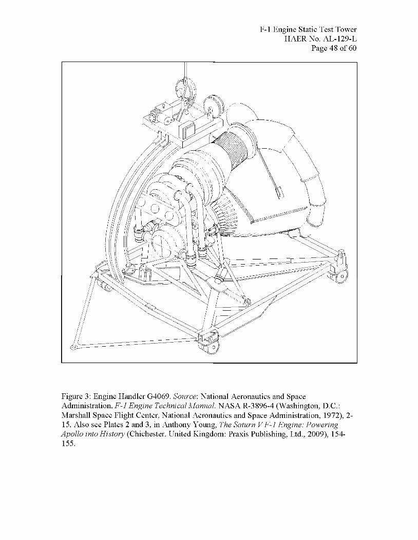
F-l Engine Static Test Tower HAERNo. AL-129-L
Page 48 of 60
Figure 3: Engine Handler G4069. Source: National Aeronautics and Space Administration, F-l Engine Technical Manual. NASA R-3896-4 (Washington, D.C.: Marshall Space Flight Center, National Aeronautics and Space Administration, 1972), 2- 15. Also see Plates 2 and 3, in Anthony Young, The Saturn VF-1 Engine: Powering Apollo into History (Chichester, United Kingdom: Praxis Publishing, Ltd., 2009), 154- 155.
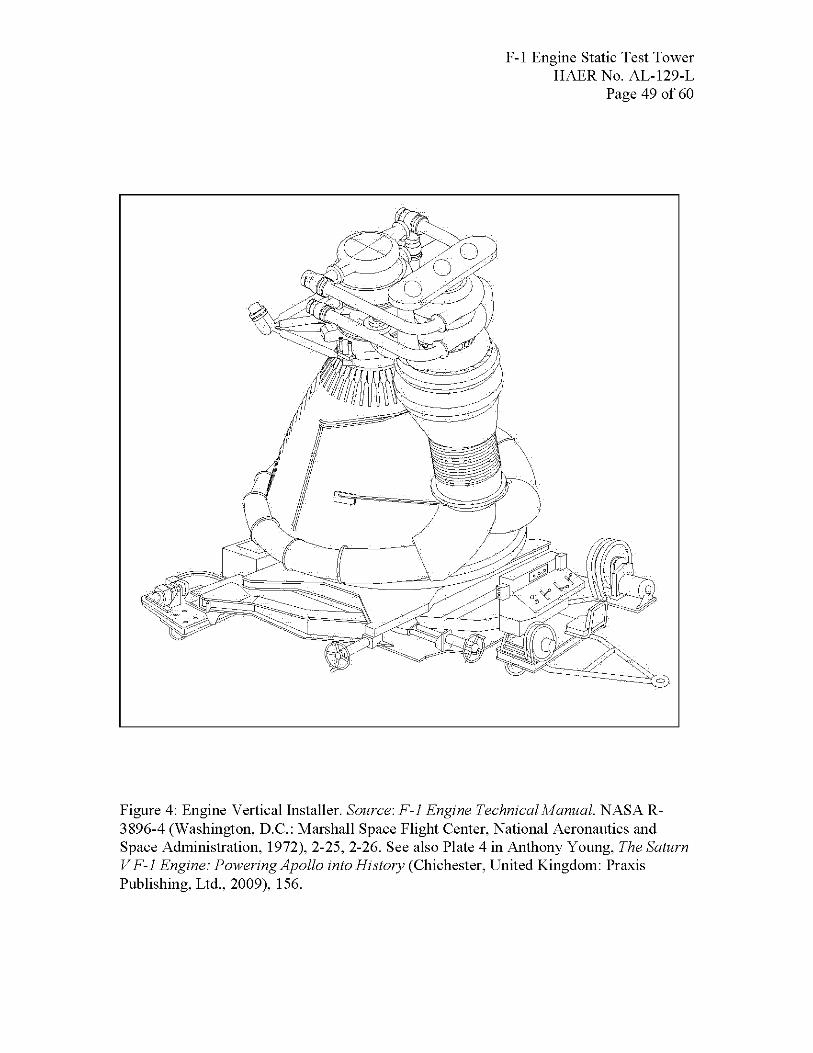
F-l Engine Static Test Tower HAERNo. AL-129-L
Page 49 of 60
Figure 4: Engine Vertical Installer. Source: F-l Engine Technical Manual. NASA R- 3896-4 (Washington, D.C.: Marshall Space Flight Center, National Aeronautics and Space Administration, 1972), 2-25, 2-26. See also Plate 4 in Anthony Young, The Saturn VF-1 Engine: Powering Apollo into History (Chichester, United Kingdom: Praxis Publishing, Ltd., 2009), 156.

F-l Engine Static Test Tower HAERNo. AL-129-L
Page 50 of 60
Figure 5: Attaching the F-l Engine to its test position. Source: F-l Engine Technical Manual. NASA R-3 896-4 (Washington, D.C.: Marshall Space Flight Center, National Aeronautics and Space Administration, 1972).
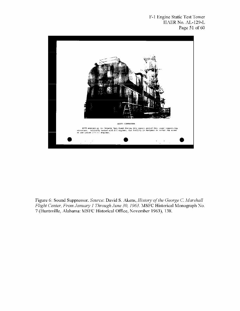
F-l Engine Static Test Tower HAERNo. AL-129-L
Page 51 of 60
MSFC erected at l.t= Interim Test Stand during this report period this suund buppres^ing ially tested Hith H-I engines, the facility in designed to soften the sound e F-l engi
Figure 6: Sound Suppressor. Source: David S. Akens, History of the George C. Marshall Flight Center, From January 1 Through June 30, 1963. MSFC Historical Monograph No. 7 (Huntsville, Alabama: MSFC Historical Office, November 1963), 138.
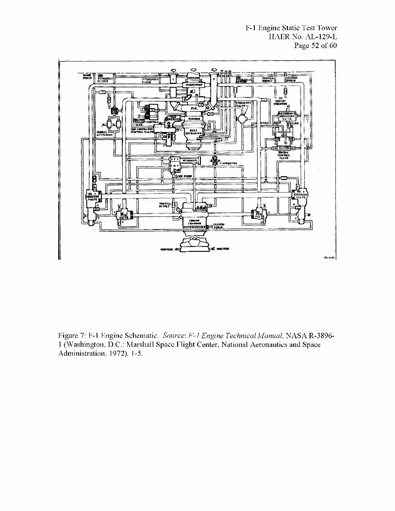
F-l Engine Static Test Tower HAERNo. AL-129-L
Page 52 of 60
Figure 7: F-l Engine Schematic. Source: F-l Engine Technical Manual. NASA R-3896- 1 (Washington, D.C.: Marshall Space Flight Center, National Aeronautics and Space Administration, 1972), 1-5.
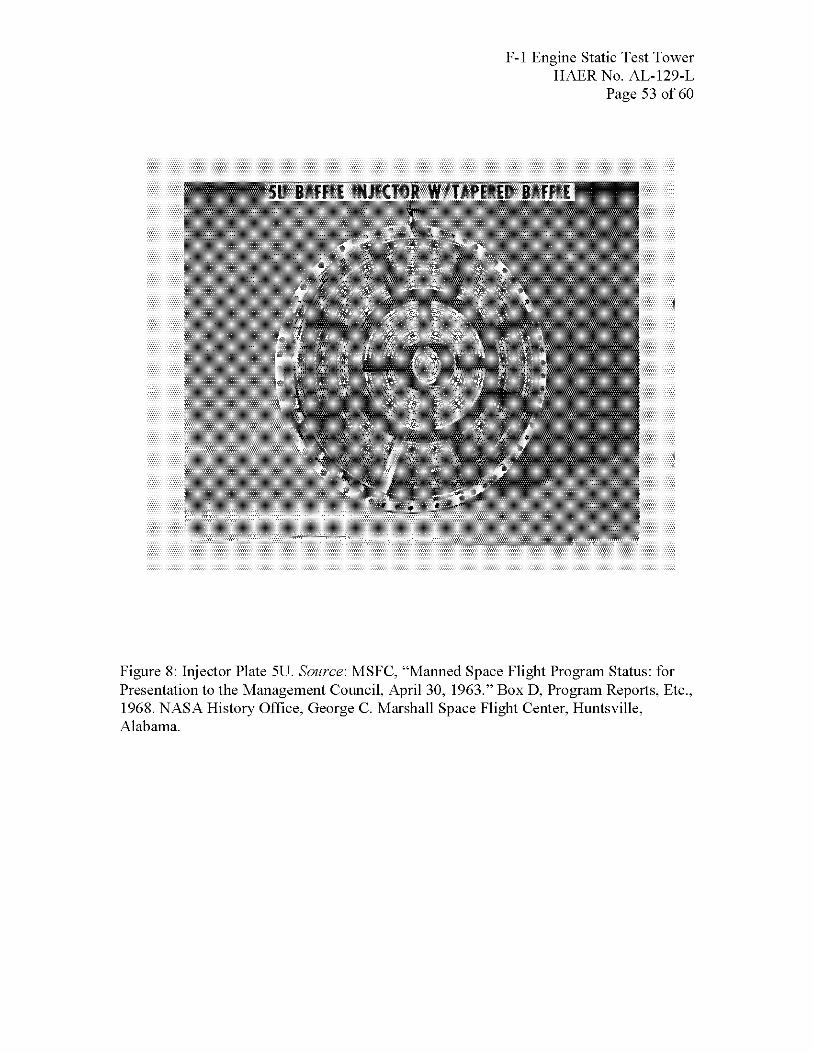
F-l Engine Static Test Tower HAERNo. AL-129-L
Page 53 of 60
Figure 8: Injector Plate 5U. Source: MSFC, "Manned Space Flight Program Status: for Presentation to the Management Council, April 30, 1963." Box D, Program Reports, Etc., 1968. NASA History Office, George C. Marshall Space Flight Center, Huntsville, Alabama.
F-l Engine Static Test Tower HAERNo. AL-129-L
Page 54 of 60
APPENDIX B
Test-Firings at the F-l Engine Test Stand George C. Marshall Space Flight Center (MSFC)/Huntsville.
Alabama
135 Table based on data drawn from "F-l ENGINE TESTS, F-l TEST STAND - WEST AREA," Test-Fire Logs,F-i Engine Time Records: R&D Test Engines, 502 Engine, 501 Engines, T-Bird Engines, Sl-C Stand, Fl-Test Stand, STTWEngines,^-\ ENGINE TIME RECORDS-A.pdf). NASA History Office, Marshall Space Flight Center, Huntsville, Alabama.
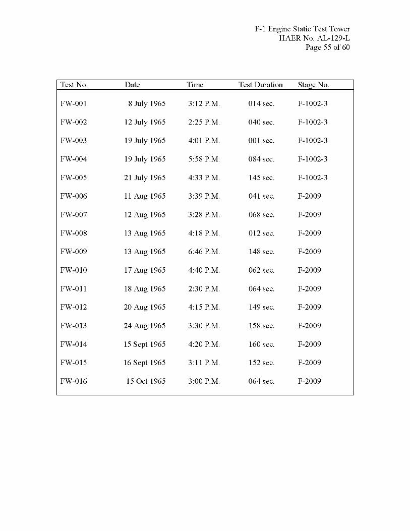
F-l Engine Static Test Tower HAERNo. AL-129-L
Page 55 of 60
Test No. Date Time Test Duration Stage No.
FW-001 8 July 1965 3:12 P.M. 014 sec. F-1002-3
FW-002 12 July 1965 2:25 P.M. 040 sec. F-1002-3
FW-003 19 July 1965 4:01 P.M. 001 sec. F-1002-3
FW-004 19 July 1965 5:58 P.M. 084 sec. F-1002-3
FW-005 21 July 1965 4:33 P.M. 145 sec. F-1002-3
FW-006 11 Aug 1965 3:39 P.M. 041 sec. F-2009
FW-007 12 Aug 1965 3:28 P.M. 068 sec. F-2009
FW-008 13 Aug 1965 4:18 P.M. 012 sec. F-2009
FW-009 13 Aug 1965 6:46 P.M. 148 sec. F-2009
FW-010 17 Aug 1965 4:40 P.M. 062 sec. F-2009
FW-011 18 Aug 1965 2:30 P.M. 064 sec. F-2009
FW-012 20 Aug 1965 4:15 P.M. 149 sec. F-2009
FW-013 24 Aug 1965 3:30 P.M. 158 sec. F-2009
FW-014 15 Sept 1965 4:20 P.M. 160 sec. F-2009
FW-015 16 Sept 1965 3:11P.M. 152 sec. F-2009
FW-016 15 0ct 1965 3:00 P.M. 064 sec. F-2009

F-l Engine Static Test Tower HAERNo. AL-129-L
Page 56 of 60
Test No. Date Time Test Duration Stage No.
FW-017 18 Mar 1966 1:30 P.M. 045 sec. F-4T2
FW-018 18 Mar 1966 4:27 P.M. 045 sec. F-4T2
FW-019 21 Mar 1966 1:59 P.M. 046 sec. F-4T2
FW-020 21 Mar 1966 4:29 P.M. 45 sec. F-4T2
FW-021 29 Mar 1966 4:08 P.M. 101 sec. F-2010
FW-022 7 Apr 1966 2:29 P.M. 45 sec. F-3013
FW-023 19 Apr 1966 3:05 P.M. 69 sec. F-4T2
FW-024 27 Apr 1966 2:03 P.M. 45 sec. F-4T2
FW-025 28 Apr 1966 1:58 P.M. 150 sec. F-4T2
FW-026 4 May 1966 2:00 P.M. 156 sec. F-4T2
FW-027 5 May 1966 1:59 P.M. 155 sec. F-4T2
FW-028 9 May 1966 1:45 P.M. 155 sec. F-4T2
FW-029 9 May 1966 3:30 P.M. 56 sec. F-4T2
FW-030 11 May 1966 1:30 P.M. 155 sec. F-4T2
FW-031 18 May 1966 1:33 P.M. 155 sec. F-4T2
FW-032 18 May 1966 3:37 P.M. 64 sec. F-4T2
FW-033 20 June 1966 2:00 P.M. 165 sec. F-5038
FW-034 21 June 1966 3:17 P.M. 165 sec. F-5038
FW-035 22 June 1966 2:03 P.M. 170 sec. F-5038
FW-036 23 June 1966 2:09 P.M. 164 sec. F-5038
FW-037 27 June 1966 2:00 P.M. 164 sec. F-5038

F-l Engine Static Test Tower HAERNo. AL-129-L
Page 57 of 60
FW-038 28 June 1966 1:30 P.M. 103 sec. F-5038
Test No. Date Time Test Duration Stage No.
FW-039 29 June 1966 12:50 P.M. 40 sec. F-5038
FW-040 29 June 1966 2:00 P.M. 162 sec. F-5038
FW-041 30 June 1966 1:07 P.M. 40 sec. F-5038
FW-042 30 June 1966 2:55 P.M. 143 sec. F-5038
FW-043 6 July 1966 2:00 P.M. 37 sec. F-5038
FW-044 12 July 1966 12:59 P.M. 168 sec. F-5038
FW-045 13 July 1966 12:54 P.M. 170 sec. F-5038
FW-046 14 July 1966 12:53 P.M. 150 sec. F-5038
FW-047 25 July 1966 1:11P.M. 41 sec. F-4017
FW-048 5 Aug 1966 12:59 P.M. 42 sec. F-2010
FW-049 9 Aug 1966 12:58 P.M. 42 sec. F-2010
FW-050 23 Aug 1966 12:55 P.M. 39 sec. F-4017
FW-051 24 Aug 1966 1:53 P.M. 45 sec. F-4017
FW-052 13 Sept 1966 12:57 P.M. 45 sec. F-3014
FW-053 21 Oct 1966 1:21P.M. 113 sec. F-4T2
FW-054 28 Oct 1966 3:22 P.M. 130 sec. F-4T2
FW-055 10Novl966 3:33 P.M. 45 sec. F-4T2
FW-056 2 Dec 1966 1:00 P.M. 45 sec. F-5038
FW-057 9 Jan 1967 1:31P.M. 45 sec. F-5038
FW-058 18 Jan 1967 2:16 P.M. 41 sec. F-5038
FW-059 10 Feb 1967 11:00 P.M. 55 sec. F-4024
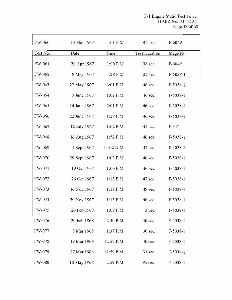
F-l Engine Static Test Tower HAERNo. AL-129-L
Page 58 of 60
FW-060 13 Mar 1967 1:01P.M. 45 sec. F-6049
Test No. Date Time Test Duration Stage No.
FW-061 20 Apr 1967 1:00 P.M. 36 sec. F-6049
FW-062 19 May 1967 1:28 P.M. 25 sec. F-5038-1
FW-063 22 May 1967 6:01 P.M. 46 sec. F-5038-1
FW-064 9 June 1967 1:02 P.M. 46 sec. F-5038-1
FW-065 14 June 1967 2:01 P.M. 46 sec. F-5038-1
FW-066 22 June 1967 1:28 P.M. 46 sec. F-5038-1
FW-067 12 July 1967 1:02 P.M. 45 sec. F-3T1
FW-068 16 Aug 1967 1:52 P.M. 46 sec. F-5038-1
FW-069 1 Sept 1967 11:02 A.M. 42 sec. F-5038-1
FW-070 29 Sept 1967 1:03 P.M. 46 sec. F-5038-1
FW-071 19 Oct 1967 1:00 P.M. 46 sec. F-5038-1
FW-072 26 Oct 1967 1:13 P.M. 47 sec. F-5038-1
FW-073 16Novl967 1:18 P.M. 49 sec. F-5038-1
FW-074 30Novl967 1:15 P.M. 46 sec. F-5038-1
FW-075 20 Feb 1968 1:08 P.M. 3 sec. F-5038-1
FW-076 20 Feb 1968 2:40 P.M. 30 sec. F-5038-1
FW-077 8 Mar 1968 1:37 P.M. 30 sec. F-5038-1
FW-078 19 Mar 1968 12:57 P.M. 30 sec. F-5038-1
FW-079 27 Mar 1968 12:59 P.M. 31 sec. F-5038-1
FW-080 10 May 1968 2:59 P.M. 95 sec. F-5038-1

FW-081
FW-082
F-l Engine Static Test Tower HAERNo. AL-129-L
Page 59 of 60
15 May 1968 3:35 P.M.
22 May 1968 1:58 P.M.
125 sec.
151 sec.
F-5038-1
F-5038-1
Test No. Date Time Test Duration Stage No.
FW-083 6 June 1968 1:10 P.M. 50 sec. F-5038-1
FW-084 6 June 1968 3:17 P.M. 40 sec. F-5038-1
FW-085 6 June 1968 5:30 P.M. 49 sec. F-5038-1
FW-086 25 June 1968 3:00 P.M. 109 sec. F-2009-1
FW-087 28 June 1968 12:30 P.M. 6 sec. F-2009-1
FW-088 28 June 1968 2:20 P.M. 40 sec. F-2009-1
FW-089 28 June 1968 4:12 P.M. 16 sec. F-2009-1
FW-090 28 June 1968 6:00 P.M. 50 sec. F-2009-1
FW-091 11 July 1968 2:00 P.M. 9 sec. F-2009-1
FW-092 11 July 1968 4:11P.M. 10 sec. F-2009-1
FW-093 11 July 1968 5:55 P.M. 53 sec. F-2009-1
FW-094 12 July 1968 4:45 P.M. 15 sec. F-2009-1
FW-095 12 July 1968 7:41 P.M. 15 sec. F-2009-1
FW-096 13 Aug 1968 12:54 P.M. 45 sec. F-2009-1
FW-097 13 Aug 1968 3:30 P.M. 140 sec. F-2009-1
FW-098 13 Aug 1968 6:30 P.M. 80 sec. F-2009-1
FW-099 15 Aug 1968 1:31P.M. 155 sec. F-2009-1
FW-100 15 Aug 1968 4:29 P.M. 155 sec. F-2009-1
FW-101 21 Aug 1968 1:27 P.M. 155 sec. F-2009-1
FW-102 21 Aug 1968 4:26 P.M. 130 sec. F-2009-1

F-l Engine Static Test Tower HAERNo. AL-129-L
Page 60 of 60
FW-103 30 Sept 1968 1:28 P.M. 160 sec. F-2009-1
FW-104 30 Sept 1968 4:56 P.M. 160 sec. F-2009-1
Test No. Date Time Test Duration Stage No.
FW-105 9 Jan 1969 1:31P.M. 160 sec. F-2009-1
FW-106 17 Jan 1969 1:29 P.M. 140 sec. F-2009-1
FW-107 13 Feb 1969 1:39 P.M. 155 sec. F-2009-1

PHOTOGRAPHS
HAER AL-129-LHAER AL-129-L
ADDENDUM TO:MARSHALL SPACE FLIGHT CENTER, F-1 ENGINE STATIC TESTSTAND(West Area Test Stand)(Building No. 4696)(Facility No. 4696)Redstone ArsenalOn Route 565 between Huntsville and DecaturHuntsville vicinityMadison CountyAlabama
HISTORIC AMERICAN ENGINEERING RECORDNational Park Service
U.S. Department of the Interior1849 C Street NW
Washington, DC 20240-0001