MSFC STANDARD FOR CONFIGURABLE LOGIC...
60
CHECK THE MASTER LIST— VERIFY THAT THIS IS THE CORRECT VERSION BEFORE USE at https://repository.msfc.nasa.gov/docs/multiprogram/MSFC-STD-3663.pdf MSFC-STD-3663 National Aeronautics and BASELINE Space Administration EFFECTIVE DATE: April 11, 2012 George C. Marshall Space Flight Center Marshall Space Flight Center, Alabama 35812 ES30 MSFC TECHNICAL STANDARDS MSFC STANDARD FOR CONFIGURABLE LOGIC DEVICE DEVELOPMENTS NOT MEASUREMENT SENSITIVE Approved for Public Release; Distribution is Unlimited Downloaded from http://www.everyspec.com
Transcript of MSFC STANDARD FOR CONFIGURABLE LOGIC...
CHECK THE MASTER LIST— VERIFY THAT THIS IS THE CORRECT VERSION BEFORE USE at
https://repository.msfc.nasa.gov/docs/multiprogram/MSFC-STD-3663.pdf
MSFC-STD-3663 National Aeronautics and BASELINE Space Administration EFFECTIVE DATE: April 11, 2012
George C. Marshall Space Flight Center Marshall Space Flight Center, Alabama 35812
ES30
MSFC TECHNICAL STANDARDS
MSFC STANDARD FOR CONFIGURABLE LOGIC DEVICE
DEVELOPMENTS
NOT MEASUREMENT
SENSITIVE
Approved for Public Release; Distribution is Unlimited
Downloaded from http://www.everyspec.com
MSFC Technical Standard ES30
Title: MSFC Standard for Configurable Logic Device Developments
Document No.: MSFC-STD-3663 Revision: Baseline
Effective Date: April 11, 2012 Page 2 of 60
CHECK THE MASTER LIST - VERIFY THAT THIS IS THE CORRECT VERSION BEFORE USE at
https://repository.msfc.nasa.gov/docs/multiprogram/MSFC-STD-3663.pdf
DOCUMENT HISTORY LOG
Status (Baseline/ Revision/ Canceled)
Document Revision
Effective Date
Description Baseline
4/11/2012 Baseline release; document authorized through MPDMS.
Downloaded from http://www.everyspec.com
MSFC Technical Standard ES30
Title: MSFC Standard for Configurable Logic Device Developments
Document No.: MSFC-STD-3663 Revision: Baseline
Effective Date: April 11, 2012 Page 3 of 60
CHECK THE MASTER LIST - VERIFY THAT THIS IS THE CORRECT VERSION BEFORE USE at
https://repository.msfc.nasa.gov/docs/multiprogram/MSFC-STD-3663.pdf
FOREWORD This Marshall technical standard defines the technical and managerial processes necessary to manage and develop electronic designs containing complex programmable logic devices, such as Field Programmable Gate Arrays (FPGAs), Application Specific Integrated Circuits (ASICs), and similar devices (sometimes referred to as “complex electronics.”) Throughout this document, a component from this family of devices is referred to as a Configurable Logic Device (CLD.)
This Standard is recommended for all MSFC projects, but is not mandatory unless specifically imposed.
Downloaded from http://www.everyspec.com
MSFC Technical Standard ES30
Title: MSFC Standard for Configurable Logic Device Developments
Document No.: MSFC-STD-3663 Revision: Baseline
Effective Date: April 11, 2012 Page 4 of 60
CHECK THE MASTER LIST - VERIFY THAT THIS IS THE CORRECT VERSION BEFORE USE at
https://repository.msfc.nasa.gov/docs/multiprogram/MSFC-STD-3663.pdf
TABLE OF CONTENTS
1.0 SCOPE..................................................................................................................................8 1.1 SCOPE .............................................................................................................................. 8
1.2 CHANGE AUTHORITY & TAILORING ....................................................................... 8
2.0 APPLICABLE DOCUMENTS ........................................................................................ 9 2.1 APPLICABLE DOCUMENTS ..................................................................................... 9
2.2 REFERENCED DOCUMENTS .................................................................................... 9
2.3 ORDER OF PRECEDENCE ....................................................................................... 10
2.4 ACKNOWLEDGEMENTS ......................................................................................... 10
3.0 DEFINITIONS....................................................................................................................10 3.1 ACRONYMS ................................................................................................................. 10
3.2 DEFINITIONS .............................................................................................................. 11
3.3 CONVENTION AND NOTATION .............................................................................. 13
4.0 GENERAL REQUIREMENTS ...................................................................... ..............13
4.1 RESPONSIBILITIES ................................................................................................ 13
4.1.1 Acquiring Organization Responsibilities ............................................................ 13
4.1.2 MSFC Engineering Directorate Responsibilities ............................................... 14
4.1.3 MSFC Safety, Reliability, and Mission Assurance (SR&MA) Directorate Responsibilities ............................................................................................. 14
4.1.4 Developing Organization Responsibilities ........................................................ 14
4.2 CLD RELATIONSHIP TO OVERALL PROGRAMMATIC APPROACH .............. 15
4.2.1 Criticality Determination ..................................................................................... 15
4.2.2 Verification and Validation, of Models and Simulations ...................................... 16
4.2.3 Peer Reviews ........................................................................................................ 16
4.2.4 Configuration Management ................................................................................. 17
4.2.5 Corrective Action ................................................................................................. 18
4.2.6 CLD Design Reviews ............................................................................................ 18
4.2.7 Acquisition Planning ............................................................................................ 19
Downloaded from http://www.everyspec.com
MSFC Technical Standard ES30
Title: MSFC Standard for Configurable Logic Device Developments
Document No.: MSFC-STD-3663 Revision: Baseline
Effective Date: April 11, 2012 Page 5 of 60
CHECK THE MASTER LIST - VERIFY THAT THIS IS THE CORRECT VERSION BEFORE USE at
https://repository.msfc.nasa.gov/docs/multiprogram/MSFC-STD-3663.pdf
5.0 DETAILED REQUIREMENTS...................................................................................19 5.1 DEFINITION/PLANNING .......................................................................................... 19
5.1.1 Unique Life Cycle ................................................................................................ 20
5.1.2 Documentation Lifecycle .................................................................................... 22
5.1.3 Organizational Approach .................................................................................... 26
5.1.4 Margins and Technical Performance Measures ................................................... 26
5.1.5 Verification and Validation Planning ................................................................... 26
5.1.6 Independent Verification ..................................................................................... 27
5.1.7 Design Maintenance, Operations, and Retirement .............................................. 27
5.2 REQUIREMENTS DEFINITION ................................................................................. 28
5.3 PRELIMINARY AND DETAILED DESIGN .............................................................. 29
5.3.1 Configurable Logic Device Identification ........................................................... 29
5.3.2 Parts Selection ....................................................................................................... 29
5.3.3 Incorporation of Off-The-Shelf or Nondevelopment Items .................................. 30
5.3.4 Safety Critical Design Identification ................................................................... 31
5.3.5 Mixed-Classification Platforms ........................................................................... 31
5.3.6 Diagram Semantics .............................................................................................. 31
5.3.7 Hardware Descriptor Language Design Standards .............................................. 31
5.3.8 Secure Design Practices ....................................................................................... 31
5.3.9 Version Control .................................................................................................... 32
5.3.10 Design Analysis Tool Selection ........................................................................... 32
5.4 IMPLEMENTATION .................................................................................................... 33
5.5 VERIFICATION & VALIDATION.............................................................................. 33
5.5.1 Analysis................................................................................................................. 34
5.5.2 Test Planning ........................................................................................................ 34
5.5.3 Test Execution ..................................................................................................... 35
5.5.4 Defect Reporting Requirements ........................................................................... 35
5.5.5 Defect Elimination ............................................................................................... 35
Downloaded from http://www.everyspec.com
MSFC Technical Standard ES30
Title: MSFC Standard for Configurable Logic Device Developments
Document No.: MSFC-STD-3663 Revision: Baseline
Effective Date: April 11, 2012 Page 6 of 60
CHECK THE MASTER LIST - VERIFY THAT THIS IS THE CORRECT VERSION BEFORE USE at
https://repository.msfc.nasa.gov/docs/multiprogram/MSFC-STD-3663.pdf
5.6 MANUFACTURING/PRODUCTION.......................................................................... 35
5.6.1 CONFIGURATION OF DELIVERED DEVICES ............................................ 36
5.7 FIELDING THE DEVICE ............................................................................................. 36
5.8 SYSTEM SAFETY ........................................................................................................ 36
5.8.1 Safety and Hazard Control ................................................................................... 36
5.8.2 NASA Independent Verification and Validation Reporting ................................ 36
5.8.3 Safety Criticality Determination ........................................................................... 36
5.8.4 Safety Critical Function Specifications ............................................................... 36
5.8.5 Safety Verification ............................................................................................... 37
5.8.6 Safety Impact Evaluation ..................................................................................... 37
5.8.7 Computing System Boundary .............................................................................. 37
5.8.8 Trend Analysis ..................................................................................................... 37
5.9 CLD QUALITYASSURANCE ...................................................................................... 37
5.10 SUPPLIER MANAGEMENT ..................................................................................... 38
5.10.1 Supplier Performance Assessment ..................................................................... 38
5.10.2 NASA Performance Insight ............................................................................... 39
5.11 POTENTIAL – DESIGN REQUIREMENT EVALUATION ..................................... 39
6.0 NOTES 40
Appendix A. Safety Critical System Specification Checklist 41
Appendix B. Design Review Checklist 47
Appendix C. Designer’s Checklist Of Best Practices 51
Appendix D. Recommendations For Conducting CLD Peer Reviews 55
Appendix E. Compliance Matrix 58
Downloaded from http://www.everyspec.com
MSFC Technical Standard ES30
Title: MSFC Standard for Configurable Logic Device Developments
Document No.: MSFC-STD-3663 Revision: Baseline
Effective Date: April 11, 2012 Page 7 of 60
CHECK THE MASTER LIST - VERIFY THAT THIS IS THE CORRECT VERSION BEFORE USE at
https://repository.msfc.nasa.gov/docs/multiprogram/MSFC-STD-3663.pdf
FIGURE
1. Notional life cycle......................................................................................................21 TABLE
I. Generic CLD Documentation....................................................................................23 II. CLD Unit Development Folder Recommended Contents.........................................24
Downloaded from http://www.everyspec.com
MSFC Technical Standard ES30
Title: MSFC Standard for Configurable Logic Device Developments
Document No.: MSFC-STD-3663 Revision: Baseline
Effective Date: April 11, 2012 Page 8 of 60
CHECK THE MASTER LIST - VERIFY THAT THIS IS THE CORRECT VERSION BEFORE USE at
https://repository.msfc.nasa.gov/docs/multiprogram/MSFC-STD-3663.pdf
1.0 SCOPE
1.1 Scope This standard applies to Configurable Logic Devices (CLDs) to the extent identified in applicable requirements or contractual documentation.
The intent of this standard is to define requirements to ensure CLD development is managed appropriately, in order to ensure delivery/fielding of robust CLD hardware. A robust device does not contain systematic un-desirable features and will respond predictability to various conditions and environments. A reliable device is robust and can demonstrate performance over a period of time based on lifetime (random) failure statistical data. Planning requires establishing standards and methodologies that are used, researching and analyzing tools and then procuring those necessary to manage and execute the project. Compliance with these process requirements is accomplished through technical insight, participation in requirements, design, and status reviews, participation in test readiness reviews, and review of documentation, including the development plans, and other artifacts and documentation. Specific responsibilities are defined in section 4.1. Although various aspects of the design of FPGA and ASIC devices are sometimes referred to as “firmware,” the usage of that terminology does not establish an equivalence to the term “firmware” as used in NASA Procedural Requirement (NPR) 7150.2, NASA Software Engineering Requirements and NPD 2820.1, NASA Software Policy. Therefore the requirements of NPR 7150.2 are not applicable to CLD designs, although some developing organizations may apply those methodologies and processes successfully in CLD designs. Current NASA approaches to CLD development is addressed in the NASA Engineering and Safety Center Technical Assessment Report, NESC-RP-09-00546 “Development, Design, Test, and Evaluation Process for Robustness of Space Flight Programmable Logic Devices.” This standard is developed consistent with that approach.
Note: When a processor is embedded within a CLD, from a software perspective, the processor is no different from a processor that is a discrete “chip”. As such, while the design and implementation of that processor into the CLD is covered by this standard, the software that will execute on that processor is covered by the NPR 7150.2 definition and requirements.
1.2 Change Authority & Tailoring Proposed changes to this standard are governed by MPR 8070.1.
Downloaded from http://www.everyspec.com
MSFC Technical Standard ES30
Title: MSFC Standard for Configurable Logic Device Developments
Document No.: MSFC-STD-3663 Revision: Baseline
Effective Date: April 11, 2012 Page 9 of 60
CHECK THE MASTER LIST - VERIFY THAT THIS IS THE CORRECT VERSION BEFORE USE at
https://repository.msfc.nasa.gov/docs/multiprogram/MSFC-STD-3663.pdf
Exceptions, tailoring, or other modifications to the requirements of this document specific to a given program/project/activity are within the authority of the responsible program/project/activity technical authority having invoked this Standard.
2.0 APPLICABLE DOCUMENTS
2.1 Applicable Documents MPR 8070.1 Administration of MSFC’s Technical Standards
MSFC–STD–3012 EEE Parts Management and Control Requirements for MSFC Space Flight Hardware
2.2 Referenced Documents The following documents contain supplemental information to guide the user in the application of this document.
NESC-RP- 09-00546 Development, Design, Test, and Evaluation Process for Robustness of Space Flight Programmable Logic Devices
MPR 7123.1 MSFC Systems Engineering Processes and Requirements
MWI 8050.1 Verification and Validation of Hardware, Software, and Ground Support Equipment for MSFC Projects
NPD 2820.1 NASA Software Policy
NPR 7150.2 NASA Software Engineering Requirements
RTCA/DO–254 Design Assurance Guidance for Airborne Electronic Hardware
ECSS–Q–60–02A Space Product Assurance ASIC and FPGA Development
The following websites may be used as a reference for users of this document. http://klabs.org/ NASA Office of Logic Design
(OLD)
Downloaded from http://www.everyspec.com
MSFC Technical Standard ES30
Title: MSFC Standard for Configurable Logic Device Developments
Document No.: MSFC-STD-3663 Revision: Baseline
Effective Date: April 11, 2012 Page 10 of 60
CHECK THE MASTER LIST - VERIFY THAT THIS IS THE CORRECT VERSION BEFORE USE at
https://repository.msfc.nasa.gov/docs/multiprogram/MSFC-STD-3663.pdf
https://nen.nasa.gov/web/avionics/pld NASA Engineering Safety Center Community of Practice for Programmable Logic Devices
http://www.hq.nasa.gov/office/codeq/software/ComplexElectronics/index.htm
NASA Assurance Process for Complex Electronics
2.3 Order of Precedence In the event of any conflict between the text of this standard and the references cited herein, the text of this standard shall take precedence. However, nothing in this text shall supersede applicable laws and regulations unless a specific exemption has been obtained.
2.4 Acknowledgements The requirements and recommendation contained in this specification are the result of MSFC studies of processes and best practices from a variety of sources, including published studies, center-level documentation at other NASA centers, and program documentation and discussions conducted as part of the Ares Project for the Constellation Program. The safety critical checklist in Appendix A is based upon computing system requirements from the Constellation program. The Design Review Checklist (Appendix B) and Designers Checklist of Best Practices (Appendix C) are both based closely upon documentation from the Goddard Space Flight Center. Other materials reviewed include the Naval Research Laboratory guidelines for the Microwave Imager/Sounder program, and a report by the Aerospace Corporation for the Air Force Space Command. 3.0 DEFINITIONS
3.1 Acronyms
The acronyms used in this standard are defined as follows: ASIC Application-Specific Integrated Circuit CDR Critical Design Review CLD Configuration Logic Device
Downloaded from http://www.everyspec.com
MSFC Technical Standard ES30
Title: MSFC Standard for Configurable Logic Device Developments
Document No.: MSFC-STD-3663 Revision: Baseline
Effective Date: April 11, 2012 Page 11 of 60
CHECK THE MASTER LIST - VERIFY THAT THIS IS THE CORRECT VERSION BEFORE USE at
https://repository.msfc.nasa.gov/docs/multiprogram/MSFC-STD-3663.pdf
CM Configuration Management CMMI Capability Maturity Model Integration CMOS Complementary Metal Oxide Semiconductor COTS Commercial Off-The-Shelf DDT&E FPGA
Design, Development, Test and Engineering Field Programmable Gate Array
HDL Hardware Descriptor Language IEC International Electromechanical Commission IP Intellectual Property ISO International Standards Organization IT IV&V
Information Technology Independent Verification and Validation
MPR Marshall Procedural Requirements NPD NASA Policy Directive NPR NASA Procedural Requirements OPR Office of Prime Responsibility PDR Preliminary Design Review SR&QA Safety, Reliability, and Quality Assurance SRR System Requirements Review V&V Verification & Validation
3.2 Definitions
Term Description Acquiring Organization The organization responsible programmatically and
technically for the development of a CLD design, a CLD device, or a component or subsystem containing one or more CLDs. With respect to this Standard, NASA is senior Acquiring Organization, but in a structured/tiered acquisition, the role of Acquiring Organization is found whenever a development is given to a vendor, subcontract, or other provider.
Best Practice A recommended approach that is intended to achieve high product quality.
Critical Function As used within this document, those functions that are either safety critical or designated mission critical functions, thus requiring the stricter control specified herein.
Downloaded from http://www.everyspec.com
MSFC Technical Standard ES30
Title: MSFC Standard for Configurable Logic Device Developments
Document No.: MSFC-STD-3663 Revision: Baseline
Effective Date: April 11, 2012 Page 12 of 60
CHECK THE MASTER LIST - VERIFY THAT THIS IS THE CORRECT VERSION BEFORE USE at
https://repository.msfc.nasa.gov/docs/multiprogram/MSFC-STD-3663.pdf
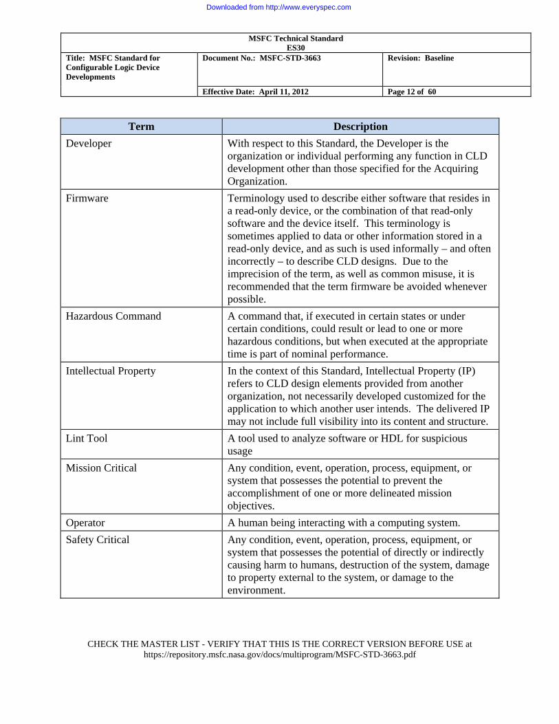
Term Description Developer With respect to this Standard, the Developer is the
organization or individual performing any function in CLD development other than those specified for the Acquiring Organization.
Firmware Terminology used to describe either software that resides in a read-only device, or the combination of that read-only software and the device itself. This terminology is sometimes applied to data or other information stored in a read-only device, and as such is used informally – and often incorrectly – to describe CLD designs. Due to the imprecision of the term, as well as common misuse, it is recommended that the term firmware be avoided whenever possible.
Hazardous Command A command that, if executed in certain states or under certain conditions, could result or lead to one or more hazardous conditions, but when executed at the appropriate time is part of nominal performance.
Intellectual Property In the context of this Standard, Intellectual Property (IP) refers to CLD design elements provided from another organization, not necessarily developed customized for the application to which another user intends. The delivered IP may not include full visibility into its content and structure.
Lint Tool A tool used to analyze software or HDL for suspicious usage
Mission Critical Any condition, event, operation, process, equipment, or system that possesses the potential to prevent the accomplishment of one or more delineated mission objectives.
Operator A human being interacting with a computing system. Safety Critical Any condition, event, operation, process, equipment, or
system that possesses the potential of directly or indirectly causing harm to humans, destruction of the system, damage to property external to the system, or damage to the environment.
Downloaded from http://www.everyspec.com
MSFC Technical Standard ES30
Title: MSFC Standard for Configurable Logic Device Developments
Document No.: MSFC-STD-3663 Revision: Baseline
Effective Date: April 11, 2012 Page 13 of 60
CHECK THE MASTER LIST - VERIFY THAT THIS IS THE CORRECT VERSION BEFORE USE at
https://repository.msfc.nasa.gov/docs/multiprogram/MSFC-STD-3663.pdf
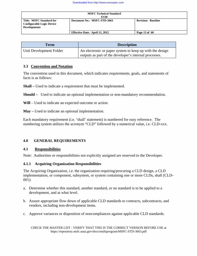
Term Description Unit Development Folder An electronic or paper system to keep up with the design
outputs as part of the developer’s internal processes. 3.3 Convention and Notation
The convention used in this document, which indicates requirements, goals, and statements of facts is as follows:
Shall – Used to indicate a requirement that must be implemented.
Should – Used to indicate an optional implementation or non-mandatory recommendation.
Will – Used to indicate an expected outcome or action.
May – Used to indicate an optional implementation.
Each mandatory requirement (i.e. ‘shall’ statement) is numbered for easy reference. The numbering system utilizes the acronym “CLD” followed by a numerical value, i.e. CLD-xxx.
4.0 GENERAL REQUIREMENTS
4.1 Responsibilities Note: Authorities or responsibilities not explicitly assigned are reserved to the Developer.
4.1.1 Acquiring Organization Responsibilities
The Acquiring Organization, i.e. the organization requiring/procuring a CLD design, a CLD implementation, or component, subsystem, or system containing one or more CLDs, shall (CLD-001):
a. Determine whether this standard, another standard, or no standard is to be applied to a development, and at what level.
b. Assure appropriate flow down of applicable CLD standards to contracts, subcontracts, and vendors, including non-development items.
c. Approve variances or disposition of noncompliances against applicable CLD standards.
Downloaded from http://www.everyspec.com
MSFC Technical Standard ES30
Title: MSFC Standard for Configurable Logic Device Developments
Document No.: MSFC-STD-3663 Revision: Baseline
Effective Date: April 11, 2012 Page 14 of 60
CHECK THE MASTER LIST - VERIFY THAT THIS IS THE CORRECT VERSION BEFORE USE at
https://repository.msfc.nasa.gov/docs/multiprogram/MSFC-STD-3663.pdf
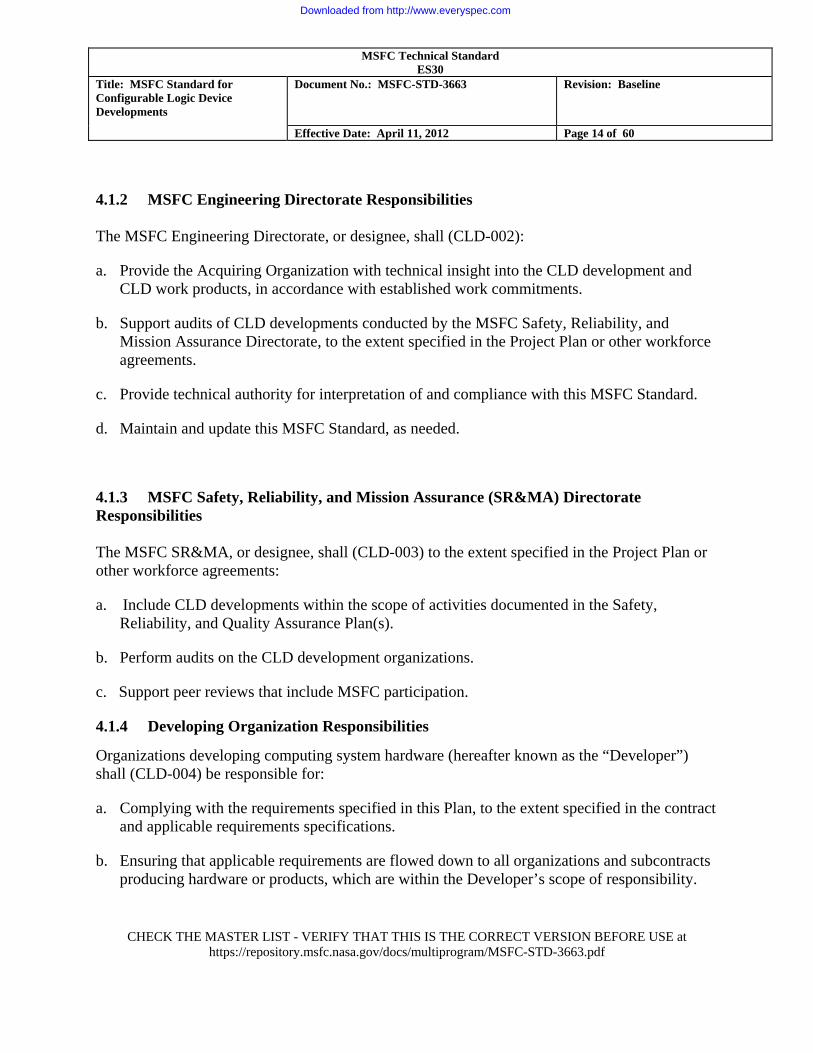
4.1.2 MSFC Engineering Directorate Responsibilities The MSFC Engineering Directorate, or designee, shall (CLD-002):
a. Provide the Acquiring Organization with technical insight into the CLD development and CLD work products, in accordance with established work commitments.
b. Support audits of CLD developments conducted by the MSFC Safety, Reliability, and Mission Assurance Directorate, to the extent specified in the Project Plan or other workforce agreements.
c. Provide technical authority for interpretation of and compliance with this MSFC Standard.
d. Maintain and update this MSFC Standard, as needed.
4.1.3 MSFC Safety, Reliability, and Mission Assurance (SR&MA) Directorate Responsibilities The MSFC SR&MA, or designee, shall (CLD-003) to the extent specified in the Project Plan or other workforce agreements:
a. Include CLD developments within the scope of activities documented in the Safety, Reliability, and Quality Assurance Plan(s).
b. Perform audits on the CLD development organizations.
c. Support peer reviews that include MSFC participation.
4.1.4 Developing Organization Responsibilities
Organizations developing computing system hardware (hereafter known as the “Developer”) shall (CLD-004) be responsible for:
a. Complying with the requirements specified in this Plan, to the extent specified in the contract and applicable requirements specifications.
b. Ensuring that applicable requirements are flowed down to all organizations and subcontracts producing hardware or products, which are within the Developer’s scope of responsibility.
Downloaded from http://www.everyspec.com
MSFC Technical Standard ES30
Title: MSFC Standard for Configurable Logic Device Developments
Document No.: MSFC-STD-3663 Revision: Baseline
Effective Date: April 11, 2012 Page 15 of 60
CHECK THE MASTER LIST - VERIFY THAT THIS IS THE CORRECT VERSION BEFORE USE at
https://repository.msfc.nasa.gov/docs/multiprogram/MSFC-STD-3663.pdf
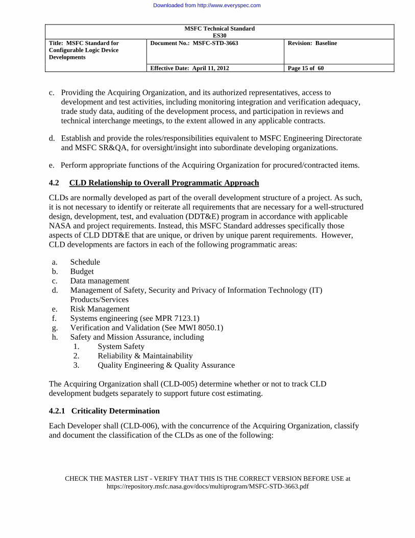
c. Providing the Acquiring Organization, and its authorized representatives, access to development and test activities, including monitoring integration and verification adequacy, trade study data, auditing of the development process, and participation in reviews and technical interchange meetings, to the extent allowed in any applicable contracts.
d. Establish and provide the roles/responsibilities equivalent to MSFC Engineering Directorate and MSFC SR&QA, for oversight/insight into subordinate developing organizations.
e. Perform appropriate functions of the Acquiring Organization for procured/contracted items.
4.2 CLD Relationship to Overall Programmatic Approach
CLDs are normally developed as part of the overall development structure of a project. As such, it is not necessary to identify or reiterate all requirements that are necessary for a well-structured design, development, test, and evaluation (DDT&E) program in accordance with applicable NASA and project requirements. Instead, this MSFC Standard addresses specifically those aspects of CLD DDT&E that are unique, or driven by unique parent requirements. However, CLD developments are factors in each of the following programmatic areas:
a. Schedule b. Budget c. Data management d. Management of Safety, Security and Privacy of Information Technology (IT)
Products/Services e. Risk Management f. Systems engineering (see MPR 7123.1) g. Verification and Validation (See MWI 8050.1) h. Safety and Mission Assurance, including
1. System Safety 2. Reliability & Maintainability 3. Quality Engineering & Quality Assurance
The Acquiring Organization shall (CLD-005) determine whether or not to track CLD development budgets separately to support future cost estimating.
4.2.1 Criticality Determination
Each Developer shall (CLD-006), with the concurrence of the Acquiring Organization, classify and document the classification of the CLDs as one of the following:
Downloaded from http://www.everyspec.com
MSFC Technical Standard ES30
Title: MSFC Standard for Configurable Logic Device Developments
Document No.: MSFC-STD-3663 Revision: Baseline
Effective Date: April 11, 2012 Page 16 of 60
CHECK THE MASTER LIST - VERIFY THAT THIS IS THE CORRECT VERSION BEFORE USE at
https://repository.msfc.nasa.gov/docs/multiprogram/MSFC-STD-3663.pdf
a. Safety critical – a characteristic in which loss of function or erroneous function could lead to loss or injury of crew or ground personnel, destruction of the system, damage to property external to the system, or damage to the environment.
b. Mission critical – a characteristic in which loss of function or erroneous function could lead to the inability to accomplish one or more delineated mission objectives.
c. Noncritical—all others.
Note, throughout this Standard, the use of the term “critical” is intended to convey a characteristic that is either safety critical, or a designated mission critical.
If changes in the application or analysis determine that a previously noncritical system is now safety or mission critical, the Developer shall (CLD-007) update the development methodology and documentation to the requirements for a safety critical application.
See also RTCA/DO–254, Design Assurance Guidance for Airborne Electronic Hardware, for guidance.
4.2.2 Verification and Validation, of Models and Simulations
The Developer shall (CLD-008) verify and validate in accordance with project requirements, any models or simulations used for final verifications that are not testable by the Developer (including testing at higher levels of assembly.)
4.2.3 Peer Reviews Peer reviews and inspections are the in-process technical examination of work products (including test benches) by the designer’s peers for the purpose of finding and eliminating defects early in the life cycle. Peer reviews are performed following defined procedures covering the preparation for the review, conducting the review itself, documenting results, reporting the results, and certifying the completion criteria.
Each Developer shall (CLD-009) define within its approach for CLD developments, the use of peer reviews, the peer review process, and the interrelationship between peer reviews and project-level formal reviews, including reporting requirements. Peer reviews shall (CLD-010) be performed, at a minimum, for the design and design products.
An effective peer reviewer must have both expert-level experience and knowledge of CLD designs. Training is important for consistency in the review process, and should be considered with selecting peer reviewers.
Downloaded from http://www.everyspec.com
MSFC Technical Standard ES30
Title: MSFC Standard for Configurable Logic Device Developments
Document No.: MSFC-STD-3663 Revision: Baseline
Effective Date: April 11, 2012 Page 17 of 60
CHECK THE MASTER LIST - VERIFY THAT THIS IS THE CORRECT VERSION BEFORE USE at
https://repository.msfc.nasa.gov/docs/multiprogram/MSFC-STD-3663.pdf
Recommendations for conducting peer reviews are provided in Appendix D and may be used as a guideline.
4.2.4 Configuration Management Configuration management establishes and maintains the integrity of the product development throughout the life cycle. Configuration management involves identifying the configuration of products that are delivered to the customer and used in development, systematically controlling changes to the configuration, and maintaining the integrity and traceability of the configuration.
Developers shall (CLD-011) implement configuration management for both the electronic configuration files (i.e., “1s and 0s”) used to configure CLD chips (including memory devices that hold the design externally to the FPGA) as well as the design files, configurations, and environments used to generate them. Configuration management for these files, may be included in software configuration management documentation and do not require separate procedures and plans to be written.
The Developer shall (CLD-012):
a. Include CLDs in appropriate configuration management plans that describe the functions, responsibilities, and authority for the implementation of configuration management for the project.
b. Track and evaluate changes to products.
c. Identify the configuration items (e.g., hardware, documents, code, data, scripts) and their versions to be controlled.
d. Establish and implement procedures designating the levels of control each identified configuration item must pass through; the persons or groups with authority to authorize changes and to make changes at each level; and the steps to be followed to request authorization for changes, process Change Requests, track changes, distribute changes, and maintain past versions.
e. Prepare and maintain records of the configuration status of configuration items.
f. Ensure that configuration audits are performed to determine the correct version of the configuration items and verify that they conform to the documents that define them.
g. Establish and implement procedures for the storage, handling, delivery, release, and maintenance of deliverable products.
Downloaded from http://www.everyspec.com
MSFC Technical Standard ES30
Title: MSFC Standard for Configurable Logic Device Developments
Document No.: MSFC-STD-3663 Revision: Baseline
Effective Date: April 11, 2012 Page 18 of 60
CHECK THE MASTER LIST - VERIFY THAT THIS IS THE CORRECT VERSION BEFORE USE at
https://repository.msfc.nasa.gov/docs/multiprogram/MSFC-STD-3663.pdf
h. Provide and maintain traceability from design to hardware or CLD code.
i. Track changes, including but not limited to both design and requirements, and provide data for review.
j. Track defects (a.k.a. “bugs”) and the resulting changes.
The Acquiring Organization, or as delegated to lower-tier configuration control boards shall (CLD-013) control delivered products, including documentation, Hardware Descriptor Language (HDL) source, programming files, data tables, and products used to generate CLDs.
4.2.5 Corrective Action
The Developer shall (CLD-014) identify inconsistencies between requirements and design products and initiate corrective actions.
The Acquiring Organization shall (CLD-015) ensure that corrective actions are taken and managed to closure when actual results and performance deviate from the plans.
4.2.6 CLD Design Reviews
Development process includes both joint management reviews and technical reviews defined in the appropriate Systems Engineering Management Plan (SEMP). Multiple design reviews may be planned and performed by both the Acquiring Organization and the Developer(s).
Each Developer shall (CLD-016) regularly hold reviews of CLD design and development activities, test procedures, status, and results with the project stakeholders and track issues to resolution. This includes formal external reviews, as well as peer reviews internal to the Developer. Specific requirements are established by systems engineering planning, and by contracts, where applicable.
See Appendix B, for recommended items to review/consider at a Design Review.
Omitting any of the detailed design phase steps increases the likelihood of having design problems and anomalies, increasing technical and programmatic risks.
Development risk increases if a robust preliminary design is not developed, documented and reviewed. Lack of a preliminary design increases the probability that requirements may be missed in the design, causing development schedule and cost impacts.
Downloaded from http://www.everyspec.com
MSFC Technical Standard ES30
Title: MSFC Standard for Configurable Logic Device Developments
Document No.: MSFC-STD-3663 Revision: Baseline
Effective Date: April 11, 2012 Page 19 of 60
CHECK THE MASTER LIST - VERIFY THAT THIS IS THE CORRECT VERSION BEFORE USE at
https://repository.msfc.nasa.gov/docs/multiprogram/MSFC-STD-3663.pdf
4.2.7 Acquisition Planning The Acquiring Organization shall (CLD-017) evaluate potential suppliers using the following criteria: a. Compliance to the mandatory requirements of this document.
b. Implementation of the best practices identified within this document.
c. The use of Capability Maturity Model Integration (CMMI) or equivalent process maturity certification for development organizations.
Note: This document does not impose a requirement for CMMI but does recognize that CMMI may be used by Developer to lend strength to their processes.
Standard data requirements documents, including two that are directly applicable to CLD developments, are available thru the MSFC Integrated Document Library. https://masterlist.msfc.nasa.gov/drm/
STD/DE-PDDD Programmable Devices Design Documentation STD/DE-PDDP Programmable Devices Development Plan
5.0 DETAILED REQUIREMENTS
The Acquiring Organization and/or the Developer may apply additional process-based approaches to their individual developments. Of particular value is the capability maturity model/integration (CMMI) approach and certification. CMMI process certification, although not a requirement for CLD developments is a best practice and may yield value.
5.1 Definition/Planning
Each Acquiring Organization shall (CLD-018) document or record the acceptance criteria and conditions for the CLD deliverables, or the CLD portion of higher-level assemblies.
The Developer shall (CLD-019), produce a development plan that documents the organization’s approach to design, development, test, and engineering/evaluation (DDT&E) of and assurance for CLDs and/or tailors their organizational specific processes and procedures. This plan is
Downloaded from http://www.everyspec.com
MSFC Technical Standard ES30
Title: MSFC Standard for Configurable Logic Device Developments
Document No.: MSFC-STD-3663 Revision: Baseline
Effective Date: April 11, 2012 Page 20 of 60
CHECK THE MASTER LIST - VERIFY THAT THIS IS THE CORRECT VERSION BEFORE USE at
https://repository.msfc.nasa.gov/docs/multiprogram/MSFC-STD-3663.pdf
subject to approval by the Acquiring Organization. The plan should include a compliance assessment per Appendix E.
Note: Development risk increases if any of the planning steps are omitted. Lack of planning increases the likelihood of cost and schedule impacts. 5.1.1 Unique Life Cycle
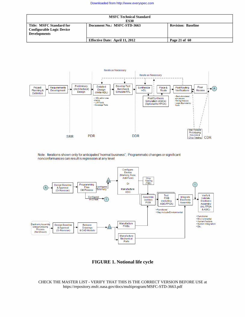
Each Developer shall (CLD-020) define the development life cycle being used for development of CLDs. A typical generic life cycle is shown in Figure 1. This life cycle is an example and is not intended to constrain the process used by an individual Developer, but may be used in the absence of specific policies. The Developer shall (CLD-021) address any significant departures from this generic template.
The work authorization gates shown in Figure 1 represent decision points between the design phase and the beginning of hardware implementation. Traditionally, proceeding to hardware implementation, except for development units, is constrained to follow CDR, unless the Acquiring Organization grants permission. The Acquiring Organization may choose to place requirements on the criteria for these gates, relative to Developer design milestones and element or project level design reviews.
Guidelines to entry/exit criteria for these phases may be found in ECSS–Q–60–02A, “Space product Assurance ASIC and FPGA development.”
Downloaded from http://www.everyspec.com
MSFC Technical Standard ES30
Title: MSFC Standard for Configurable Logic Device Developments
Document No.: MSFC-STD-3663 Revision: Baseline
Effective Date: April 11, 2012 Page 21 of 60
CHECK THE MASTER LIST - VERIFY THAT THIS IS THE CORRECT VERSION BEFORE USE at
https://repository.msfc.nasa.gov/docs/multiprogram/MSFC-STD-3663.pdf
FIGURE 1. Notional life cycle
Downloaded from http://www.everyspec.com
MSFC Technical Standard ES30
Title: MSFC Standard for Configurable Logic Device Developments
Document No.: MSFC-STD-3663 Revision: Baseline
Effective Date: April 11, 2012 Page 22 of 60
CHECK THE MASTER LIST - VERIFY THAT THIS IS THE CORRECT VERSION BEFORE USE at
https://repository.msfc.nasa.gov/docs/multiprogram/MSFC-STD-3663.pdf
5.1.2 Documentation Lifecycle
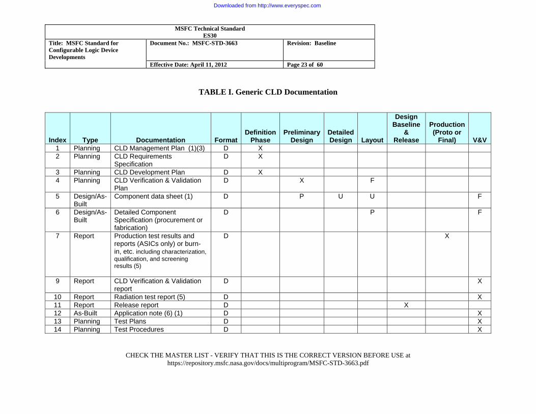
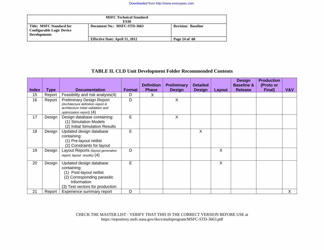
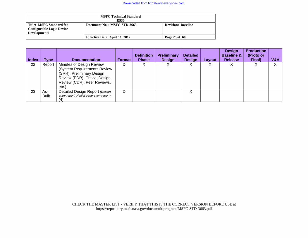
CLD developments require unique documentation, above the traditional drawings and analysis produced for a circuit card design. Each Developer shall (CLD-022) document in their Development Plan an approved list of deliverables based on Tables I and II and the implementation of this MSFC Standard and any additional requirements imposed by the Acquiring Organization or by contract. Reference is made to ECSS–Q–60–02A, Space Product Assurance ASIC and FPGA Development, for recommendations about the content and preparation of documentation associated with CLD developments.
Table I shows the typical documentation products for a critical CLD development that require acquirer review and approval. Table II shows documentation that may be included in unit development folders (UDFs) and made available through peer review processes, in lieu of formally deliverable documentation. For CLDs that are noncritical, critical with low complexity, prototype, development units, or non-flight products, the Acquiring Organization should agree to a reduced documentation set.
The following notes apply:
1. May be combined into other project documentation. 2. V&V of the device may be treated as part of the printed wiring board (PWB) and/or
assembly in which it functions. 3. Required for stand-alone developments deliverable to an organizationally separate customer;
As part of the overall project planning for FPGA/ASIC designs conducted by the same responsible organization performing PWB (and/or higher) design activities.
4. Results to be summarized at formal customer design review. 5. If performed. 6. Required if chips are delivered directly to a customer, unless all characteristics are included
in the release report. 7. Where required by the customer:
D = Document or Drawing: Either electronic or both electronic and hardcopy E = Electronic: Format of files and media must be mutually agreed upon F = Final P = Preliminary U = Update X = Required
Downloaded from http://www.everyspec.com
MSFC Technical Standard ES30
Title: MSFC Standard for Configurable Logic Device Developments
Document No.: MSFC-STD-3663 Revision: Baseline
Effective Date: April 11, 2012 Page 23 of 60
CHECK THE MASTER LIST - VERIFY THAT THIS IS THE CORRECT VERSION BEFORE USE at
https://repository.msfc.nasa.gov/docs/multiprogram/MSFC-STD-3663.pdf
TABLE I. Generic CLD Documentation
Index Type Documentation FormatDefinition
Phase Preliminary
Design Detailed Design Layout
Design Baseline
& Release
Production(Proto or
Final) V&V 1 Planning CLD Management Plan (1)(3) D X 2 Planning CLD Requirements
Specification D X
3 Planning CLD Development Plan D X 4 Planning CLD Verification & Validation
Plan D X F
5 Design/As-Built
Component data sheet (1) D P U U F
6 Design/As-Built
Detailed Component Specification (procurement or fabrication)
D P F
7 Report Production test results and reports (ASICs only) or burn-in, etc. including characterization, qualification, and screening results (5)
D X
9 Report CLD Verification & Validation report
D X
10 Report Radiation test report (5) D X 11 Report Release report D X 12 As-Built Application note (6) (1) D X 13 Planning Test Plans D X 14 Planning Test Procedures D X
Downloaded from http://www.everyspec.com
MSFC Technical Standard ES30
Title: MSFC Standard for Configurable Logic Device Developments
Document No.: MSFC-STD-3663 Revision: Baseline
Effective Date: April 11, 2012 Page 24 of 60
CHECK THE MASTER LIST - VERIFY THAT THIS IS THE CORRECT VERSION BEFORE USE at
https://repository.msfc.nasa.gov/docs/multiprogram/MSFC-STD-3663.pdf
TABLE II. CLD Unit Development Folder Recommended Contents
Index Type Documentation FormatDefinition
Phase Preliminary
Design Detailed Design Layout
Design Baseline &
Release
Production(Proto or
Final) V&V 15 Report Feasibility and risk analysis(4) D X 16 Report Preliminary Design Report
(Architecture definition report & architecture initial validation and optimization report) (4)
D X
17 Design Design database containing: (1) Simulation Models (2) Initial Simulation Results
E X
18 Design Updated design database containing: (1) Pre-layout netlist (2) Constraints for layout
E X
19 Design Layout Reports (layout generation report; layout results) (4)
D X
20 Design Updated design database containing: (1) Post-layout netlist (2) Corresponding parasitic Information (3) Test vectors for production
E X
21 Report Experience summary report D X
Downloaded from http://www.everyspec.com
MSFC Technical Standard ES30
Title: MSFC Standard for Configurable Logic Device Developments
Document No.: MSFC-STD-3663 Revision: Baseline
Effective Date: April 11, 2012 Page 25 of 60
CHECK THE MASTER LIST - VERIFY THAT THIS IS THE CORRECT VERSION BEFORE USE at
https://repository.msfc.nasa.gov/docs/multiprogram/MSFC-STD-3663.pdf
Index Type Documentation FormatDefinition
Phase Preliminary
Design Detailed Design Layout
Design Baseline &
Release
Production(Proto or
Final) V&V 22 Report Minutes of Design Review
(System Requirements Review (SRR), Preliminary Design Review (PDR), Critical Design Review (CDR), Peer Reviews, etc.)
D X X X X X X X
23 As-Built
Detailed Design Report (Design entry report; Netlist generation report) (4)
D X
Downloaded from http://www.everyspec.com
MSFC Technical Standard ES30
Title: MSFC Standard for Configurable Logic Device Developments
Document No.: MSFC-STD-3663 Revision: Baseline
Effective Date: April 11, 2012 Page 26 of 60
CHECK THE MASTER LIST - VERIFY THAT THIS IS THE CORRECT VERSION BEFORE USE at
https://repository.msfc.nasa.gov/docs/multiprogram/MSFC-STD-3663.pdf
5.1.3 Organizational Approach
Each developing organization shall (CLD-023) define the organizational approach utilized for CLD developments, to include:
a. Management, assurance, and control functions. b. Data management and configuration management. c. Plans for process improvement and process institutionalization. d. Roles and responsibilities for SR&QA. e. Version control for electronic design files (prior to entry into formal configuration
management processes). f. The use of peer reviews and the peer review process. g. Processes for identification and management of risks internal to the development
organization. This documentation may be one or more stand-alone documents, or may be included in overall planning documents that have greater scope than CLDs.
5.1.4 Margins and Technical Performance Measures
The Developer shall (CLD-024) define CLD margins, specific to the device type utilized and in relation to the avionics architecture level technical performance measure (TPM), in order to maintain performance, for both input/output (I/O) pins, and logic modules (gates, flip-flops, etc.) These margins shall (CLD-025) be phased to reflect decreasing margin requirements progressively at Preliminary Design Review (PDR), CDR, fabrication/programming, and delivery.
The Developer shall (CLD-026) track CLD resource utilization, compared to the defined margin as TPMs and report in accordance with the requirements of the Acquiring Organization.
5.1.5 Verification and Validation Planning Verification and validation activities can span multiple iterations of the design cycle that leads ultimately to the final product. V&V can take place during any/all of the following: a. Simulations. b. Developmental tests (e.g. ‘breadboard’, ‘engineering model’, etc.). c. Temperature range testing. d. Integration tests with software or higher level systems.
Downloaded from http://www.everyspec.com
MSFC Technical Standard ES30
Title: MSFC Standard for Configurable Logic Device Developments
Document No.: MSFC-STD-3663 Revision: Baseline
Effective Date: April 11, 2012 Page 27 of 60
CHECK THE MASTER LIST - VERIFY THAT THIS IS THE CORRECT VERSION BEFORE USE at
https://repository.msfc.nasa.gov/docs/multiprogram/MSFC-STD-3663.pdf
The Developer shall (CLD-027) perform requirements validation to ensure that the CLD performs as intended in the customer environment.
Each Developer shall (CLD-028) plan both verification and validation activities, to include methods, environments, and criteria, subject to the approval of the Acquiring Organization.
The Developer shall (CLD-029) define and implement an approach utilizing independent personnel (i.e., separate from the designer(s)) for critical CLDs.
For CLDs that implements one or more critical functions, the Developer’s design team shall (CLD-030) document for the V&V activity the CLD design characteristics, including the results from the analysis of customer and other stakeholder requirements, design features, and the operational concepts. References to higher level documents can be used. This document provides traceability for the implementation and establishes the guidelines for the test and verification steps.
Note: The CLD functional requirements are derived from the board-level and system-level requirements and typically include:
a. Functions to be implemented.
b. Performance (speed, critical timing, throughput).
c. Interface description (signal levels, timing, software, data formats).
d. Environmental constraints (thermal, radiation level at part, mission duration).
e. Testability requirements (Joint Test Action Group (JTAG)), board scan, software, observable internal points).
f. Responses to off-nominal inputs and conditions, including handing of detected errors.
5.1.6 Independent Verification
The Acquiring Organization shall (CLD-031) specify any external verification activities to be performed in-line with the Developer, and whether they are milestones that impede the Developer’s progress. 5.1.7 Design Maintenance, Operations, and Retirement
Planning for operations, maintenance, and retirement begins early in the life cycle. Operational concepts and scenarios are derived from customer requirements and validated in the operational
Downloaded from http://www.everyspec.com
MSFC Technical Standard ES30
Title: MSFC Standard for Configurable Logic Device Developments
Document No.: MSFC-STD-3663 Revision: Baseline
Effective Date: April 11, 2012 Page 28 of 60
CHECK THE MASTER LIST - VERIFY THAT THIS IS THE CORRECT VERSION BEFORE USE at
https://repository.msfc.nasa.gov/docs/multiprogram/MSFC-STD-3663.pdf
or simulated environment. Design maintenance activities sustain the product after it is delivered to the customer until retirement.
The Developer shall (CLD-032), consistent with the requirements of the Acquiring Organization, provide for the operations and maintenance of delivered CLD design products, and maintain the design from the time of delivery until design retirement.
The Developer shall (CLD-033) complete and deliver CLDs (or other end-products containing CLD design elements) to the Acquiring Organization (or designee) with appropriate documentation to support the operations and maintenance phase of the life cycle.
The Developer shall (CLD-034):
a. Document the maintenance plans through operations, maintenance, and retirement activities.
b. Implement operations, maintenance, and retirement activities as defined in the respective plans.
c. Complete and deliver the product to the customer with appropriate documentation to support the operations and maintenance phase of the life cycle.
5.2 Requirements Definition The Developers shall (CLD-035) maintain bidirectional traceability of requirements to the project plans and work products throughout the life cycle, including traceability reports submitted at identified points in the lifecycle. Traceability reports shall (CLD-036) be available electronically. For each CLD that implements one or more safety critical functions, the Developer shall (CLD-037) either:
a. Develop a requirements specification (Index 2 from Table I) for the device or devices; or
b. Include specific requirements for the CLD device in subsections of specifications at either the board level or higher assembly.
The Developer or the Acquiring Organization may as a best-practice implement this requirement for noncritical CLDs that are highly complex.
Downloaded from http://www.everyspec.com
MSFC Technical Standard ES30
Title: MSFC Standard for Configurable Logic Device Developments
Document No.: MSFC-STD-3663 Revision: Baseline
Effective Date: April 11, 2012 Page 29 of 60
CHECK THE MASTER LIST - VERIFY THAT THIS IS THE CORRECT VERSION BEFORE USE at
https://repository.msfc.nasa.gov/docs/multiprogram/MSFC-STD-3663.pdf
5.3 Preliminary and Detailed Design A typical design process is divided into a Preliminary Design Phase and a Detailed Design Phase (often called the Critical Design Phase.) During the Preliminary Design, requirements are translated into an architecture, block diagrams, data flows, and preliminary resource estimates (e.g. gate counts, pin counts, etc.) Critical modules of the design may be prototyped or developed in detail to prove feasibility, refine resource estimates, or as risk mitigation. This phase normally culminates with a Preliminary Design Review (PDR). During the Detailed Design Phase, the preliminary design is updated and expanded to fully address all requirements. Simulation test benches will also be developed and used to confirm the functionality of the design. Prior to entering the Implementation phase, a peer review is normally held. See Appendix C for a list of best practices to consider during design. 5.3.1 Configurable Logic Device Identification
The developing organization shall (CLD-038) generate a list of CLDs to be developed and identify whether each device implements critical functions.
5.3.2 Parts Selection The parts to be used for the filed implementation CLDs shall (CLD-039) be selected and documented, along with the criteria used for making the selection. The part used for the flight FPGA implementations should be selected as early in the development cycle as feasible. This will allow for the long procurement cycles normally associated with flight FPGA devices. In addition to the mandatory requirements of the program EEE Parts Management and Control Requirements, and MSFC-STD-3012, the following factors should be taken into consideration in selecting a device family and specific part number:
a. Package style.
b. Reliability/flight qualification status/heritage.
c. Radiation specs (total dose and single event effects).
d. Estimate of utilization:
1. Use prior experience.
2. Find similar design and get gate count for target technology.
3. Overestimate if a guess is necessary.
Downloaded from http://www.everyspec.com
MSFC Technical Standard ES30
Title: MSFC Standard for Configurable Logic Device Developments
Document No.: MSFC-STD-3663 Revision: Baseline
Effective Date: April 11, 2012 Page 30 of 60
CHECK THE MASTER LIST - VERIFY THAT THIS IS THE CORRECT VERSION BEFORE USE at
https://repository.msfc.nasa.gov/docs/multiprogram/MSFC-STD-3663.pdf
4. Quantity needed.
e. Speed rating.
f. The long procurement cycles normally associated with flight grade devices.
g. The availability of equivalent commercial grade devices that may be desirable in the development of breadboards and test boards. For cost reasons, equivalent commercial devices may be considered for the development of breadboards and test beds.
5.3.3 Incorporation of Off-The-Shelf or Nondevelopment Items The Developer of CLDs that include nondevelopment items (i.e., design elements that are reused from another application, or that are procured or obtained from a source outside their developmental control such as intellectual property (IP)) shall (CLD-040) ensure that the inclusion of non-development items have identifiable and bounded impacts upon the overall function and reliability of the CLD, and the overall circuit design, including the identification and management of any appropriate risks, in accordance with the Developers risk management processes.
The Developer shall (CLD-041) ensure that when a heritage or non-developmental product is to be acquired by the Developer, the following conditions are satisfied:
a. The requirements that are to be met by the non-developmental item are identified.
b. The non-developmental item includes documentation to fulfill its intended purpose (e.g., usage instructions).
c. Proprietary, usage, ownership, warranty, licensing rights, and transfer are addressed.
d. Future support for the off-the-shelf product is planned.
e. Off-the-shelf item is validated to the same level of confidence as would be required of the developed items, although this validation may take place as part of the validation of a higher assembly.
When selecting IP for use, the design and assurance teams should consider: a. The format of the IP provided (e.g. HDL code, encrypted netlist, etc.) b. The availability of documentation (test procedures, instructions, scripts, netlists, test
benches, etc.), c. Heritage of the IP (i.e. where has it been fielded before and what was the result of that
application)
Downloaded from http://www.everyspec.com
MSFC Technical Standard ES30
Title: MSFC Standard for Configurable Logic Device Developments
Document No.: MSFC-STD-3663 Revision: Baseline
Effective Date: April 11, 2012 Page 31 of 60
CHECK THE MASTER LIST - VERIFY THAT THIS IS THE CORRECT VERSION BEFORE USE at
https://repository.msfc.nasa.gov/docs/multiprogram/MSFC-STD-3663.pdf
d. Cost (one time licensing fees, verses per use fees) Technical support provided
5.3.4 Safety Critical Design Identification
Each CLD design, (including but not limited to HDL designs, schematic gates designs, etc.) shall (CLD-042) define and utilize a method of notating critical design elements in design documentation.
5.3.5 Mixed-Classification Platforms
When safety critical and non safety critical design elements are both included within a single physical CLD device, the Developer shall (CLD-043) ensure that the level of potential interaction/interference between the safety critical and non safety critical elements is bounded so as to ensure safe operation.
As a best practice, avoid mixing safety critical and non safety critical elements in a single physical CLD, when feasible and practical.
5.3.6 Diagram Semantics Developers shall (CLD-044) include definition of the semantics used in all diagrams provided as artifacts of compliance or certifications.
5.3.7 Hardware Descriptor Language Design Standards
Each Developer utilizing HDL shall (CLD-045) define and utilize HDL coding standards for each design classification (e.g., critical, noncritical, etc.) for the HDL developments performed. Parent organizations should consider the use of common coding standards across multiple design organizations, in order to facilitate effective reviews and design insight.
Examples of the types of HDL standards that may be defined include, but are not limited to:
a. Naming conventions to allow recognition of the function of signals by their name.
b. Use of the comment header of the HDL design to capture nomenclature.
c. Use modular design to ease testability, readability, and simulation.
5.3.8 Secure Design Practices
Developers shall (CLD-046) produce and follow secure design practices to ensure the delivered products are not vulnerable to either:
Downloaded from http://www.everyspec.com
MSFC Technical Standard ES30
Title: MSFC Standard for Configurable Logic Device Developments
Document No.: MSFC-STD-3663 Revision: Baseline
Effective Date: April 11, 2012 Page 32 of 60
CHECK THE MASTER LIST - VERIFY THAT THIS IS THE CORRECT VERSION BEFORE USE at
https://repository.msfc.nasa.gov/docs/multiprogram/MSFC-STD-3663.pdf
a. Unauthorized access to either the internal design.
b. Unauthorized control of the functions of the hardware.
5.3.9 Version Control
The Developer shall (CLD-047) implement version control at the point in the lifecycle by the Developer for all files in accordance with the program‘s configuration management plan, providing the following features: a. Ease of tracking changes.
b. Reverting to an earlier version of the code.
c. Archiving
5.3.10 Design Analysis Tool Selection The Developer shall (CLD-048) evaluate and select appropriate design analysis tools, with consideration given to each of the following. 5.3.10.1 Use of Lint Tools A “lint tool” is a product that analyzes the HDL design for various syntax and construct errors, that may not be found during synthesis, such as non portable constructs. The designers should make frequent use of lint tool checks prior to both simulation and synthesis. 5.3.10.2 HDL Rule Checkers Other HDL Rule Checkers can be used to provide configurable rules checking, specific to the developers specific design requirements. When available, these tools should be used, and the results incorporated into the HDL design during both the pre-simulation and pre-synthesis phases of design. 5.3.10.2 Code Coverage
A code coverage tool is used to assess what percentage of an HDL design has been exercised during simulations. Code coverage tools should be used to help assess the confidence in the quality of the design.
Downloaded from http://www.everyspec.com

MSFC Technical Standard ES30
Title: MSFC Standard for Configurable Logic Device Developments
Document No.: MSFC-STD-3663 Revision: Baseline
Effective Date: April 11, 2012 Page 33 of 60
CHECK THE MASTER LIST - VERIFY THAT THIS IS THE CORRECT VERSION BEFORE USE at
https://repository.msfc.nasa.gov/docs/multiprogram/MSFC-STD-3663.pdf
5.4 Implementation During the implementation phase, the functional design is targeted to the physical device and the configuration documentation and files created. Typically, this includes step such as: a. Performing Vendor Specific Place and Route
b. Selecting and/or documenting constraints and settings (e.g. fixed pins, minimal clock skew paths, etc.).
c. Verify post-route.
d. Developing the procedures and altered item drawings for configuration of FPGA targets.
As a best practice, consider the use of a script to perform place and route functions, as this will ensure repeatability between runs by reducing the chance of human error.
As part of the post-route verification, the design and assurance teams shall (CLD-049) review the timing report as well as logs from vendor and analysis tools for errors, warnings and notes. Any errors or warnings that are not corrected should be thoroughly understood and rationale developed for not making further design changes.
5.5 Verification & Validation Verification activities include design reviews, engineering peer reviews, simulations, post place-and-route analysis, and post-programming verifications, and the physical lab environment. Validation (i.e., to demonstrate that a verified device will satisfy its intended use in its intended environment) is typically performed at a higher systems level. The Developer shall (CLD-050) perform the planned verification and validations of CLD development products.
Each Developer shall (CLD-051) record, address, and track to closure the results of verification and validation activities.
For each safety critical verification, the Developer shall (CLD-052) include test in the actual hardware (prototype or final) intended for fielding.
Downloaded from http://www.everyspec.com
MSFC Technical Standard ES30
Title: MSFC Standard for Configurable Logic Device Developments
Document No.: MSFC-STD-3663 Revision: Baseline
Effective Date: April 11, 2012 Page 34 of 60
CHECK THE MASTER LIST - VERIFY THAT THIS IS THE CORRECT VERSION BEFORE USE at
https://repository.msfc.nasa.gov/docs/multiprogram/MSFC-STD-3663.pdf
5.5.1 Analysis The synchronous design of an FPGA shall (CLD-053) be verified by static timing analysis, or alternatively by post-route timing analyses using a place and route tool and test vector simulation with timing checkers performed at the primitive level. As a design goal, CLD code coverage thru analysis should be at least 100% for all CLD designs. If 100 percent code coverage is not achieved, the Developer shall (CLD-054) either increase the number of simulation cases, and/or document the rationale retaining each uncovered statement. 5.5.2 Test Planning The Developer shall (CLD-055) develop and maintain Test Plan(s) and Test Procedure(s):
a. To be consistent with requirements.
b. To include a description of test preparations, including hardware and software, including:
1. Test descriptions, including:
a. Test identifier.
b. Requirements addressed by the test case.
c. Prerequisite conditions.
d. Test input.
2. Instructions for conducting procedure.
3. Expected test results, including criteria for evaluating results and assumptions and constraints.
4. Criteria for evaluating results.
5. Requirements traceability.
6. Identification of test configuration.
7. Sufficient information to ensure that tests are repeatable, including the defined use of random number generator seeds.
Downloaded from http://www.everyspec.com
MSFC Technical Standard ES30
Title: MSFC Standard for Configurable Logic Device Developments
Document No.: MSFC-STD-3663 Revision: Baseline
Effective Date: April 11, 2012 Page 35 of 60
CHECK THE MASTER LIST - VERIFY THAT THIS IS THE CORRECT VERSION BEFORE USE at
https://repository.msfc.nasa.gov/docs/multiprogram/MSFC-STD-3663.pdf
5.5.3 Test Execution During CLD testing, the Developer shall (CLD-056):
a. Perform tests as defined in document test plans.
b. Ensure that the implementation of each requirement is verified to the requirement.
c. Include evaluation test results and document the evaluation.
d. Document defects identified during testing and track to closure.
e. Maintain traceability from the test procedures to the requirements.
f. Ensure that CLD hardware is tested either on the target circuit board, or a high-fidelity simulation.
5.5.4 Defect Reporting Requirements The Developer shall (CLD-057) implement problem reporting and resolution for CLD defects in accordance with program requirements. 5.5.5 Defect Elimination The Developer of safety critical CLD designs shall (CLD-058) identify the approaches and tools to be used to demonstrate the absence of design defects in HDL or post-synthesis products. The checklists in Appendix A may be used or used as guidelines in developing specific criteria. 5.6 Manufacturing/Production The Altered-Item Drawing defines the process and tools necessary to program the correct FPGA device as called for in the assembly parts list. The Developer shall (CLD-059) develop CLD altered-item drawings containing, at a minimum, the following information: a. Identification of altered item marking.
b. Identification of altered item configuration (a.k.a. “programming”) files including traceability back to the source HDL, scripts, tool versions, and test benches.
c. Identification of the original unaltered part.
d. Processing instructions 1. Handling
2. Marking
3. Programming
4. Inspections.
Downloaded from http://www.everyspec.com
MSFC Technical Standard ES30
Title: MSFC Standard for Configurable Logic Device Developments
Document No.: MSFC-STD-3663 Revision: Baseline
Effective Date: April 11, 2012 Page 36 of 60
CHECK THE MASTER LIST - VERIFY THAT THIS IS THE CORRECT VERSION BEFORE USE at
https://repository.msfc.nasa.gov/docs/multiprogram/MSFC-STD-3663.pdf
5.6.1 Configuration of Delivered Devices The Developer shall (CLD-060) perform configuration or reconfiguration of deliverable CLD components (including those included in higher-level assemblies) in accordance with approved work authorization documentation (e.g., drawings, procedures, etc.), utilizing the current approved configuration management controlled baseline of the design, unless another version is explicitly authorized, and monitored by the Developer’s quality assurance organization. The Developer shall (CLD-061) reflect the results of the configuration process (including traceability, resolution of anomalies, serial numbers, etc.) in the as-built documentation of the hardware.
5.7 Fielding The Device
A configured CLD chip is fielded by assembly onto a circuit card. At this stage, traditional/exiting electronic engineering, manufacturing, and quality assurance techniques dominate. However, the design of the CLD is not validated until the card and/or higher assembly is shown to meet the requirements that are traceable to the CLD.
5.8 System Safety
5.8.1 Safety and Hazard Control The Developer shall (CLD-062) ensure that CLDs are included in documented assurance planning and that appropriate analysis is performed to determine critical functions and hazards. 5.8.2 NASA Independent Verification and Validation Reporting CLD developments identified by the Acquiring Organization for project NASA Independent Verification and Validation (IV&V) support plan shall (CLD-063) provide access to IV&V facility personnel for CLD products and data produced in accordance with the requirements of this plan. 5.8.3 Safety Criticality Determination During the concept or formulation phase of each CLD development, the Developer shall (CLD-064 determine whether the CLD implements safety critical functions. Note: The system criticality determines the overall criticality of hardware, but the Developer identifies specific CLDs implementing safety critical functions in support of that higher-order determination. 5.8.4 Safety Critical Function Specifications For all safety critical CLD specifications, the Developer shall (CLD-065):
a. Perform the specification completeness checklist of Appendix A.
Downloaded from http://www.everyspec.com
MSFC Technical Standard ES30
Title: MSFC Standard for Configurable Logic Device Developments
Document No.: MSFC-STD-3663 Revision: Baseline
Effective Date: April 11, 2012 Page 37 of 60
CHECK THE MASTER LIST - VERIFY THAT THIS IS THE CORRECT VERSION BEFORE USE at
https://repository.msfc.nasa.gov/docs/multiprogram/MSFC-STD-3663.pdf
b. Document and implement an approach used to demonstrate correctness, consistency and completeness of CLD requirements specifications.
c. Identify within the specification all safety-related requirements.
5.8.5 Safety Verification Using the system specification and associated design and implementation, the Acquiring Organization shall (CLD-066) ensure that all safety-related requirements for safety critical CLD designs have been implemented correctly and verified by testing and any other appropriate verification methods. 5.8.6 Safety Impact Evaluation Each Developer shall (CLD-067) evaluate any changes to safety critical CLDs, including those that result from problem or discrepancy resolution, for potential safety impacts, including the creation of new hazard contributions and impacts, modification of existing hazard controls or mitigations, or detrimental effect on safety critical software or hardware. 5.8.7 Computing System Boundary Developers and the Acquiring Organization (for CLDs implemented into higher order systems) shall (CLD-068) define in hazard reports the boundaries of the computing system element within a safety critical control system. For example, if a non-critical CLD failure within a critical circuit were to fail, the boundary of fault propagation would need to be addressed (e.g. at the circuit, card, box, or system level.) 5.8.8 Trend Analysis The Acquiring Organization shall (CLD-069) ensure the analysis and measurement of performance trend data for safety critical computing hardware, including the development and execution of plans to improve performance measures that do not meet defined expectations. This function may be delegated to the Developer. 5.9 CLD QualityAssurance A successful CLD developments require a coordinated effort between engineering and S&MA throughout the entire life-cycle. During the phase in which HDL is being designed, the focus is more upon process assurance, transitioning to quality engineering for the hardware implementation of the devices. S&MA provides assessment of the trade studies and evaluation of the high level design and an analysis of the top-level architecture S&MA reviews all simulation and analysis results.
Downloaded from http://www.everyspec.com
MSFC Technical Standard ES30
Title: MSFC Standard for Configurable Logic Device Developments
Document No.: MSFC-STD-3663 Revision: Baseline
Effective Date: April 11, 2012 Page 38 of 60
CHECK THE MASTER LIST - VERIFY THAT THIS IS THE CORRECT VERSION BEFORE USE at
https://repository.msfc.nasa.gov/docs/multiprogram/MSFC-STD-3663.pdf
The Developer shall (CLD-070) establish quality assurance processes and guidelines to address both process assurance during the design, and quality assurance during the manufacturing phase of CLDs. The Acquiring Organization may establish quality assurance requirements that flow to the Developer. The Developer should: a. Communicate quality assurance issues to staff and management. b. Use an established escalation mechanism to ensure resolution of issues. c. Track noncompliance issues to resolution. d. Establish and maintain records of all quality assurance activities for the length of the
contract. 5.10 Supplier Management
For subcontracted CLD work, the Developer performs the role of Acquiring Organization unless those functions are reserved by plan or contract to the original Acquiring Organization.
5.10.1 Supplier Performance Assessment
Each Acquiring Organization shall (CLD-071) assess the supplier’s (and the suppliers’ subcontractors) performance to include:
a. Handling of project requirements changes.
b. Accurate transformation of high-level project requirements into detailed requirements and designs.
c. Specification of interfaces between the supplier’s product and systems external to it.
d. Adequacy of the supplier’s risk management planning and implementation.
e. Adequacy of the supplier’s integration and test plan and its implementation in accordance with the required activities in the projects integration and test plans.
f. Adequacy of the supplier’s configuration management plan and its implementation in accordance with the required activities of the project’s configuration management plan.
g. The content and frequency of progress reports, product metrics, and process metrics submitted in response to measurement plans.
h. The supplier’s delivery, integration, and verification, and validation processes.
Downloaded from http://www.everyspec.com
MSFC Technical Standard ES30
Title: MSFC Standard for Configurable Logic Device Developments
Document No.: MSFC-STD-3663 Revision: Baseline
Effective Date: April 11, 2012 Page 39 of 60
CHECK THE MASTER LIST - VERIFY THAT THIS IS THE CORRECT VERSION BEFORE USE at
https://repository.msfc.nasa.gov/docs/multiprogram/MSFC-STD-3663.pdf
5.10.2 NASA Performance Insight
Each Developer shall (CLD-072) require suppliers (including subcontractors) to provide electronic access by authorized NASA project personnel for in-process and supplementary computing system technical documents and files that are developed for NASA projects, in accordance with the contract and NASA insight planning.
5.11 Potential – Design Requirement Evaluation
The Acquiring Organization and the Developer shall (CLD-073) evaluate the following design requirements for applicability and potential incorporation into appropriate requirements specifications for CLDs or computing systems containing CLDs. Where both hardware and software elements are present in a computing system, the implementation of these requirements should be applied at the computing system level (i.e. the combination of hardware and software). This approach, rather than allocating requirements separately to hardware and software, enables a holistic consideration of the potential contributors and combinations of contributors to hazards and hazard controls. Note: As used in the following list, the word ‘shall’ is not a mandatory requirement of this standard, but is draft language for possible incorporation into design specifications.
a. Hazardous function control. Computing systems shall provide hazardous function control where the inadvertent activation or deactivation of the function or capability could result in an identified critical or catastrophic hazard.
b. Safe initialization. Computing systems shall initialize to a known, safe state. Circuitry interfaced to the CLD shall take into consideration the transient nature of inputs/outputs of the CDL during power-up/power-down conditions.
c. State transition. Computing systems shall safely transition between all predefined known states.
d. Orderly shutdown. Computing systems that implement termination of safety critical functions shall perform orderly, controlled shut downs of those functions to known, safe states.
e. Off-nominal power. Safety critical computing systems shall establish a safe or powered-down state when self-monitoring functions detect off-nominal power conditions.
f. Operator overrides. Computing system overrides shall require at least two independent actions by the operator.
Downloaded from http://www.everyspec.com
MSFC Technical Standard ES30
Title: MSFC Standard for Configurable Logic Device Developments
Document No.: MSFC-STD-3663 Revision: Baseline
Effective Date: April 11, 2012 Page 40 of 60
CHECK THE MASTER LIST - VERIFY THAT THIS IS THE CORRECT VERSION BEFORE USE at
https://repository.msfc.nasa.gov/docs/multiprogram/MSFC-STD-3663.pdf
g. Command sequence. Where execution of commands out of sequence can cause a hazard, the computing system shall reject commands received out of sequence.
h. Inadvertent memory modification. Computing systems shall detect inadvertent memory modification and recover to a known, safe state.
i. Anomaly recovery. Computing systems shall establish a predefined safe state prior to the operational time predicted to cause a critical failure, following detection of predetermined indications of incorrect or incomplete processing.
j. External input. Computing systems shall discriminate between valid and invalid input from external sources and reject the invalid input while remaining in safe operations.
k. Integrity checks. Computing systems shall perform integrity checks on input and output across the computing system boundary.
l. Command rejection. Computing systems shall reject hazardous commands that do not meet prerequisite checks for execution.
m. Prerequisite checks. Computing systems shall perform prerequisite checks prior to the execution of hazardous commands
n. Inhibit display. Computing systems shall make available for display to the operators and/or other circuitry, the status of inhibits used to control hazards.
o. Inhibit state change. For commands that change the state of an inhibit, the computing system shall require a unique command for each state transition for each inhibit.
6.0 NOTES
None.
Downloaded from http://www.everyspec.com
MSFC Technical Standard ES30
Title: MSFC Standard for Configurable Logic Device Developments
Document No.: MSFC-STD-3663 Revision: Baseline
Effective Date: April 11, 2012 Page 41 of 60
CHECK THE MASTER LIST - VERIFY THAT THIS IS THE CORRECT VERSION BEFORE USE at
https://repository.msfc.nasa.gov/docs/multiprogram/MSFC-STD-3663.pdf
APPENDIX A. SAFETY CRITICAL SYSTEM SPECIFICATION CHECKLIST
The following checklist items apply to the development and documentation of safety critical computing system specifications, including CLDs. These items are provided to ensure the comprehensiveness of these specifications. Not all items are appropriate to all designs.
a. Demonstrate completeness of human-computer interface requirements criteria including: 1. Specification of the events to be queued. 2. Specification of the type and number of event queues to be provided (such as alert or
routine). 3. Ordering scheme within the queue (priority versus time of arrival). 4. Operator notification mechanism for items inserted in the queue. 5. Operator review and disposal commands for queue entries. 6. Queue entry deletion and rejection. 7. Observability of the system state. 8. For every data item displayable to a human (values and labels):
(a) What events cause this item to be displayed? (b) Can and should the display of this item ever be updated once it is displayed? If so,
what events should cause the update? Events that trigger updates may be: external observables; the passage of time; actions taken by the viewing operator; actions taken by other operators
(c) What events should cause this data display to disappear? b. Demonstrate completeness of system state requirements including:
1. The system and software starting in a safe state. Interlocks are initialized or checked to be operational at system startup, including startup after temporarily overriding interlocks.
2. The internal software model of the process is updated to reflect the actual process state at initial startup and after temporary shutdown.
3. All system and local variables are properly initialized upon startup, including clocks. 4. The behavior of the software with respect to inputs received before startup, after
shutdown, or when the computer is temporarily disconnected from the process (off-line) is specified.
5. The maximum time the computer waits before the first input is specified. 6. Paths from fail-safe (partial or total shutdown) states are specified. 7. The time in a safe but reduced-function state is specified.
Downloaded from http://www.everyspec.com
MSFC Technical Standard ES30
Title: MSFC Standard for Configurable Logic Device Developments
Document No.: MSFC-STD-3663 Revision: Baseline
Effective Date: April 11, 2012 Page 42 of 60
CHECK THE MASTER LIST - VERIFY THAT THIS IS THE CORRECT VERSION BEFORE USE at
https://repository.msfc.nasa.gov/docs/multiprogram/MSFC-STD-3663.pdf
8. Interlock failures should result in the halting of hazardous functions. 9. There is a response specified for the arrival of an input in any state, including
indeterminate states. 10. Systems using redundancy should specify how the system establishes state consistency
across all redundant units. 11. Systems using redundancy should specify how failed units are identified and removed
from the system. Note: this requirement is meant to address Byzantine agreement issues.
c. Demonstrate completeness of input and output variable requirements including:
1. The specification should address all information available from each sensor. Note: if information available from a sensor is to be ignored, the specification should say so.
2. Legal output values that are never produced are checked for potential specification incompleteness.
3. The specification should identify any groupings of input values that must be received and processed in a time-homogenous manner.
d. Demonstrate completeness of requirements for events that trigger state changes including:
1. Robustness criteria: (a) Every state should have a behavior (transition) defined for every possible input. (b) The logical OR of the conditions on every transition out of any state should form
a tautology. Note: A tautology is a statement containing more than one sub-statement, that is true regardless of the truth values of its parts (e.g., “either the valve is open OR the valve is not open”).
(c) Every state should have a behavior (transition) defined in case there is no input for a given period of time (a timeout).
(d) Every state should have defined state transitions for exceptional conditions or document that the exceptional conditions have no safety impact. Exceptional conditions include debug exceptions, nonmaskable interrupts, breakpoint, overflow, bounds check, invalid op code, coprocessor not available, co-processor error, floating point exception (e.g., division error), segment or gate not present, stack fault, general protection failure, page fault, or other exceptional conditions or interrupts unique to the implementation.
2. Nondeterminism criterion: (a) The behavior of the state machine is deterministic.
3. Value and timing assumptions:
Downloaded from http://www.everyspec.com
MSFC Technical Standard ES30
Title: MSFC Standard for Configurable Logic Device Developments
Document No.: MSFC-STD-3663 Revision: Baseline
Effective Date: April 11, 2012 Page 43 of 60
CHECK THE MASTER LIST - VERIFY THAT THIS IS THE CORRECT VERSION BEFORE USE at
https://repository.msfc.nasa.gov/docs/multiprogram/MSFC-STD-3663.pdf
(a) All incoming values are checked and a response specified in the event of an out-of-range or unexpected value.
(b) All inputs are fully bound in time, and the proper behavior specified in case the limits are violated or an expected input does not arrive.
(c) A trigger involving the nonexistence of an input is fully bounded in time. (d) A minimum and maximum load assumption is specified for every interrupt
signaled event whose arrival rate is not dominated (limited) by another type of event.
(e) The computing system should check the minimum-arrival-rate for each physically distinct communication path.
(f) The computing system should query its environment with respect to inactivity over each communication path.
(g) The response to excessive inputs (violations of load assumptions) is specified. (h) When the desired response to an overload condition is performance degradation,
the specified degradation is smooth. (i) When the desired response to an overload condition is performance degradation,
the operators are informed of the degradation. e. Demonstrate output specification completeness including:
1. Safety critical outputs are checked for reasonableness and for hazardous values and timing.
2. For the largest interval in which both input and output loads are assumed and specified, the absorption rate of the output environment should equal or exceed the input arrival rate. The absorption rate here is the rate at which the output environment is consuming the load.
3. Contingency action is specified when the output absorption rate limit is to be exceeded. 4. Update timing requirements or other solutions to potential overload problems, such as
operator event queues, are specified. 5. Automatic update and deletion requirements for information in the human/computer
interface are specified. 6. The required disposition for obsolete queue events should include specification of what
to do when the event is currently being displayed and when it is not. 7. All inputs used in specifying output events are properly limited in the time they can be
used (data age). 8. Output commands that may not be able to be executed immediately are limited in the
time they are valid.
Downloaded from http://www.everyspec.com
MSFC Technical Standard ES30
Title: MSFC Standard for Configurable Logic Device Developments
Document No.: MSFC-STD-3663 Revision: Baseline
Effective Date: April 11, 2012 Page 44 of 60
CHECK THE MASTER LIST - VERIFY THAT THIS IS THE CORRECT VERSION BEFORE USE at
https://repository.msfc.nasa.gov/docs/multiprogram/MSFC-STD-3663.pdf
9. Incomplete hazardous action sequences (transactions) should have a finite duration specified.
10. Upon exceeding the duration limit of a hazardous action sequence the software should cancel the sequence automatically, return to a safe state, and inform the operator.
11. Revocation of a partially completed action sequence should address the specification of multiple times and conditions under which varying automatic cancellation or postponement actions are taken.
12. Operator warnings are issued in the event of revocation of a partially completed action sequence.
13. A latency factor is included when an output is triggered by an interval of time without a specified input and the upper bound on the interval is not a simple, observable event. The latency factor represents the interval of time during which the receipt of new information cannot change an output O even though it arrives prior to the actual output of O.
14. Contingency action is specified to handle events that occur within the latency period. 15. A latency factor is specified for changeable human-computer interface data displays. 16. Appropriate contingency action is specified for data affecting the human/computer
interface display that arrives within the latency period. 17. A hysteresis delay action is specified for human-computer interface data to allow time
for human interpretation. 18. The specification should state what to do if data should have been changed during the
hysteresis period. f. Demonstrate completeness of output to trigger event relationship requirements including:
1. Basic feedback loops, as defined by the process control function, are included in the software requirements. Note: In a basic feedback loop there must be one or more inputs that the software can use to detect the effect of any output on the process: the requirements must include appropriate checks on these inputs in order to detect internal or external failures or errors.
2. Every output to which a detectable input is expected should have associated with it a requirement to handle the normal response.
3. Every output to which a detectable input is expected should have requirements to handle a response that is missing, too late, too early, or has an unexpected value.
4. Every output to which a detectable input is expected should have requirements to handle anomalous conditions that could be checked. An example of such an anomalous condition is an open circuit for a sensor.
Downloaded from http://www.everyspec.com
MSFC Technical Standard ES30
Title: MSFC Standard for Configurable Logic Device Developments
Document No.: MSFC-STD-3663 Revision: Baseline
Effective Date: April 11, 2012 Page 45 of 60
CHECK THE MASTER LIST - VERIFY THAT THIS IS THE CORRECT VERSION BEFORE USE at
https://repository.msfc.nasa.gov/docs/multiprogram/MSFC-STD-3663.pdf
5. Spontaneous receipt of a non-spontaneous input is detected and responded to as an abnormal condition.
6. Stability requirements are specified when the process is potentially unstable. g. Demonstrate completeness of the specification of transitions between states:
1. All specified states are reachable from the initial state. A state qm is said to be reachable from state qn if there exists a path from qn to qm and the logical AND of the predicates in the instantiated predicate sequence si corresponding to that path does not result in a contradiction.
2. Desired recurrent behavior is part of at least one cycle. 3. Required sequences of events are implemented in and limited by the specified
transitions. 4. States should not inhibit the production of later required outputs. 5. Output commands that are physically reversible are reversible. 6. If x is to be reversible by y, there is a path between the state where x is issued and a
state where y is issued. 7. Preemption requirements are specified for any multi-step transactions in conjunction
with all other possible control activations. 8. Soft and hard failure modes are eliminated for all hazard-reducing outputs. A soft
failure mode is one in which the loss of the ability to receive a particular input could inhibit the software from providing an output with a particular value, while a hard failure mode involves the loss of the ability to receive an input that prevents the software from producing that output value. An output is hazard reducing if it leads to a state having a lower risk level; likewise, an output is hazard-increasing if it leads to a state having a higher risk level.
9. Hazard-increasing outputs should have both soft and hard failure modes. 10. Multiple paths are provided for state changes that maintain or enhance safety. 11. Multiple inputs or triggers are provided for paths from safe to hazardous states. 12. States should correctly handle the processing of items placed into a queue when in a
prior state. h. Demonstrate constraint satisfaction by showing that the requirements include the identified
project-specific safety requirements and are consistent with the identified software system safety constraints, including: 1. Transitions should satisfy software system safety requirements and constraints.
Downloaded from http://www.everyspec.com
MSFC Technical Standard ES30
Title: MSFC Standard for Configurable Logic Device Developments
Document No.: MSFC-STD-3663 Revision: Baseline
Effective Date: April 11, 2012 Page 46 of 60
CHECK THE MASTER LIST - VERIFY THAT THIS IS THE CORRECT VERSION BEFORE USE at
https://repository.msfc.nasa.gov/docs/multiprogram/MSFC-STD-3663.pdf
2. Reachable hazardous states are eliminated or, if that is not possible, their frequency and duration reduced to only those states needed to achieve the goals of the system.
i. Demonstrate that the requirements are consistent with the following general safety policy:
1. There are no paths to undesired hazardous states. 2. All paths from a hazardous state should lead to safe states. Note that time in the
hazardous state should be minimized, and that contingency action may be necessary to reduce risk while in the hazardous state. Note also that it may not be possible to build a completely safe system, i.e., it may not be possible to get from every hazardous state to a safe state. In that event, the system must be redesigned or some risk accepted.
3. If a safe state cannot be reached from a hazardous state within an acceptable amount of time, all remaining paths from that hazardous state should lead to the least risk state available given the hazard and the environmental conditions, and at least one such path should exist.
Downloaded from http://www.everyspec.com
MSFC Technical Standard ES30
Title: MSFC Standard for Configurable Logic Device Developments
Document No.: MSFC-STD-3663 Revision: Baseline
Effective Date: April 11, 2012 Page 47 of 60
CHECK THE MASTER LIST - VERIFY THAT THIS IS THE CORRECT VERSION BEFORE USE at
https://repository.msfc.nasa.gov/docs/multiprogram/MSFC-STD-3663.pdf
APPENDIX B. DESIGN REVIEW CHECKLIST
1. Part Parameters and Deratings a. Data book part parameters may not match the part’s operating environment. b. Derate (see MSFC-STD-3012 for specific criteria) for
i. Temperature ii. Age iii. Voltage iv. Radiation v. Excess load capacitance
2. Timing analysis a. Analyze, for each clocked device:
i. Tsu (setup time) and Th (hold time) for all clocked inputs ii. Tpw (pulse width time) of clocks, asynchronous set, clear, and load inputs iii. Set and clear recovery time iv. Show all clock inputs and asynchronous inputs are free from both static (010 or
101) and dynamic (001011 or 110100) hazards. b. Parallel clocking c. Clock skew d. Timing of analog circuitry e. Minimum propagation delays f. Calculation of pulse shortening g. Transition times in delay calculations h. Clocking handled properly i. All clock-domain crossings are handled properly j. Asynchronous inputs filtering for meta-stability issues k. Time critical paths of each device and their timing margins l. Worst case timing analysis at the device and board levels
3. Completeness of simulations performed:
a. Best Case (Lowest Temperature, Highest Operating Voltage, Zero Radiation, Best Process)
Downloaded from http://www.everyspec.com

MSFC Technical Standard ES30
Title: MSFC Standard for Configurable Logic Device Developments
Document No.: MSFC-STD-3663 Revision: Baseline
Effective Date: April 11, 2012 Page 48 of 60
CHECK THE MASTER LIST - VERIFY THAT THIS IS THE CORRECT VERSION BEFORE USE at
https://repository.msfc.nasa.gov/docs/multiprogram/MSFC-STD-3663.pdf
b. Worst Case (Highest Temperature, Lowest Operating Voltage, Maximum Radiation, Slowest Process)
c. Simulation code/circuitry coverage (i.e. simulations adequately tests all sections of code and circuitry)
d. Percent of nets in each device covered by the fault simulation (i.e., percent of nets exercised by the test vectors and their effect of faults are observable at the device's primary output)
4. Gate Output Loading
a. Show that no gate output drive capacities have been exceeded b. High output drive currents may:
i. Affect output voltage levels and propagation delays ii. Cause thermal problems resulting in part damage
5. Interface Margins
a. All gates must have their input logic level thresholds met. i. Different part families ii. Digital and analog part interfaces
b. Decreased interface margins i. Increase noise susceptibility ii. Can affect the operation of some parts iii. Increase Icc of Complementary Metal Oxide Semiconductor (CMOS) parts
c. Many parts have maximum input transition times d. Slew rates e. Analyze input requirements of analog circuits f. Driving mixtures of TTL and CMOS
6. State Machines a. Analyze state machines for i. Unused states and lock-up ii. Simultaneous assertion of flip-flop sets and clears iii. Reset conditions and homing sequences b. Be careful with asynchronous state machines
Downloaded from http://www.everyspec.com

MSFC Technical Standard ES30
Title: MSFC Standard for Configurable Logic Device Developments
Document No.: MSFC-STD-3663 Revision: Baseline
Effective Date: April 11, 2012 Page 49 of 60
CHECK THE MASTER LIST - VERIFY THAT THIS IS THE CORRECT VERSION BEFORE USE at
https://repository.msfc.nasa.gov/docs/multiprogram/MSFC-STD-3663.pdf
7. Asynchronous Interfaces a. i.e., where the setup and hold times of incoming signals at receiving flip-flops cannot be
guaranteed. b. Synchronize asynchronous inputs c. Don’t use synchronizers to solve timing problems 8. Resets a. POR assertion and release voltages b. Reset Tpw must consider i. Longest reset Tpw specified for parts ii. Power supply ramp rate iii. Oscillator start-up time c. Reset should be synchronized d. No unintended execution of external Commands on power-up 9. Part Safety Conditions a. Protection of ESD sensitive parts b. Input voltage levels c. Tri-state output overlap d. Floating inputs e. Use of internal IC protection diodes f. Internal fan-out of signals g. External source/sink current and voltage level compatibility, and the use of shorted output
pins to increase drive current h. Absolute maximum ratings! 10. Cross-Strap Signals a. Must provide fault isolation i. No powering of modules via cross-strap circuitry ii. Failure of one box does not cause failure of another iii. Sharing of cross-strap gates 11. Circuit Interconnections a. Signal integrity
Downloaded from http://www.everyspec.com
MSFC Technical Standard ES30
Title: MSFC Standard for Configurable Logic Device Developments
Document No.: MSFC-STD-3663 Revision: Baseline
Effective Date: April 11, 2012 Page 50 of 60
CHECK THE MASTER LIST - VERIFY THAT THIS IS THE CORRECT VERSION BEFORE USE at
https://repository.msfc.nasa.gov/docs/multiprogram/MSFC-STD-3663.pdf
i. Termination of high edge-rate signals ii. Drivers and receivers for off-board signals b. Noise considerations i. Off-board connections of edge-sensitive inputs ii. Edge rates of harness signals iii. Harness noise threat model iv. Noise susceptibility analysis of input circuitry 12. Bypass Capacitance Analysis a. On-board bulk and bypass capacitance i. Power supply line inductance ii. Circuit operating frequency iii. Component current requirements iv. Vendor recommendations b. Capacitor frequency response c. Capacitor placement 13. Special Pins a. Know what each pin on every device does and make sure it is properly used i. Mode pin on FPGAs ii. JTAG pins b. No-connect pins 14. Testability a. Design with testing in mind and incorporate the resources needed to facilitate it. Consider
observability during implementation, and how to debug the circuit while the part is on the (test and/or flight) board.
Downloaded from http://www.everyspec.com
MSFC Technical Standard ES30
Title: MSFC Standard for Configurable Logic Device Developments
Document No.: MSFC-STD-3663 Revision: Baseline
Effective Date: April 11, 2012 Page 51 of 60
CHECK THE MASTER LIST - VERIFY THAT THIS IS THE CORRECT VERSION BEFORE USE at
https://repository.msfc.nasa.gov/docs/multiprogram/MSFC-STD-3663.pdf
APPENDIX C. DESIGNER’S CHECKLIST OF BEST PRACTICES
The following recommendations are provided to assist designers in following sound development practices. Developing HDL Designs
• Follow Guidelines, checklists, Style Guides, and Coding Standards. • Document your code properly. Inline documentation helps both the original designer
at a later date, and future engineering personnel who may assume responsibility for the design.
• Document the purpose of each procedure or function. • Use inline comments to explain why and how any tricks to achieve the design are
necessary. • Consider the electrical implications of the code. A CLD design is a hardware
implementation, not software. Some of the points below require action at the board level, outside the part. Communicate issues with the board designer:
1. Reset Practices
a. Typically asynchronously applied and synchronously removed 2. Timing Practices
a. Synchronous design b. Asynchronous inputs c. Signals which cross different clock boundaries
3. Logic Practices 4. Error Handling
a. Design for return to safe state if the unexpected occurs in inputs b. Consider Error-handling in every circuit … “what happens if…” and design the
circuit to get to a safe state and continue. 5. Power Related
a. Proper power supply decoupling. b. Power supply sequencing. c. Distribute simultaneously switching output pins around periphery to avoid
overloading supplies and causing ground-bounce. 6. Interfacing
a. Verify correct I/O levels are being used. Choose best I/O drivers. − Use the slowest edge rates possible given the design constraints. − Handle power-up/power-down where I/O may not be valid, to prevent
an invalid state. − Don’t allow bus contention.
Downloaded from http://www.everyspec.com
MSFC Technical Standard ES30
Title: MSFC Standard for Configurable Logic Device Developments
Document No.: MSFC-STD-3663 Revision: Baseline
Effective Date: April 11, 2012 Page 52 of 60
CHECK THE MASTER LIST - VERIFY THAT THIS IS THE CORRECT VERSION BEFORE USE at
https://repository.msfc.nasa.gov/docs/multiprogram/MSFC-STD-3663.pdf
− Don’t allow tri-state buses to float in the center region. − Input slew rate specification must be met. − Perform signal integrity analysis of all the interfaces to determine the
need for external impedance matching termination. − De-bounce and de-glitch interfaces from mechanical devices. Use
minimum bandwidth necessary to observe the signal. 7. Testability
− Plan your design with testing in mind and incorporate the resources needed to facilitate it. Consider observability as you implement your design. Think about how you will debug the circuit while the part is on the (BB/ETU/Flight) board.
− Reserve test pins as test-only pins. Buffer the signals provided to the test pins from the internal circuitry.
Develop Test Code –The following guidelines should be observed:
a. Follow the test sequence identified in the test procedure. Refer to the assigned test number for each test.
b. Use Self-Checking/documenting test-benches. c. Analyze code coverage of simulation and test vectors. d. Automate tests using scripts for repeatability and unattended runs.
Simulate Functional code using test-benches
a. Review tests. b. Review waveforms for sanity check. c. Capture I/O to other chips/systems d. Share with interfacing design engineers. e. Take the time to discuss results at this point; it can save lots of hassles later. f. Chase down all warnings and errors reported by simulator.
• Understand why they are there. • Document any decision to ignore them.
Synthesize the design
a. Use equivalent to flight part from the beginning. b. Set timing constraints in synthesis using constraint files. c. Use loading for each pin by reviewing schematics and specs for each interfacing part.
Downloaded from http://www.everyspec.com

MSFC Technical Standard ES30
Title: MSFC Standard for Configurable Logic Device Developments
Document No.: MSFC-STD-3663 Revision: Baseline
Effective Date: April 11, 2012 Page 53 of 60
CHECK THE MASTER LIST - VERIFY THAT THIS IS THE CORRECT VERSION BEFORE USE at
https://repository.msfc.nasa.gov/docs/multiprogram/MSFC-STD-3663.pdf
d. Set critical paths if pushing part speed in any particular path. e. Begins familiarity with critical paths. f. Using constraint files assists with self-documenting design. g. Review output files and logs for synthesis. h. Understand all warnings and if you decide to ignore any, document the reason why. i. Search through the netlist for issues. For example, search for flip-flops with both
asynchronous preset and clear. These should not be used, and point to interpretation issues in the code. Search for latches; may be unintended result of coding style.
Transfer netlist to vendor-specific place & route tool
a. Set timing constraints. Document and archive constraints files for reproducibility and review.
b. Double-check false paths / multi-clock paths. c. Set proper flight part
1. Package 2. Temp range (MIL range suggested to ensure sufficient timing margin) 3. Voltages (Core, I/O) 4. Radiation level
d. Fix pin locations e. Run Place and Route. f. Export Min-Typ-Max Standard Delay Format (SDF) files for simulation
1. Min/Max delays will be contained within this file, ranging from the best case to the worst case.
Post-Route Verification
a. Review all logs from vendor tools for errors, warnings, and notes. b. Review timing report to verify that the longest routes make sense. c. Timing Analysis
1. Use the vendor’s Static Timing Analysis (STA) Tool 2. Include delays to/from pads on board 3. Consider clock source and delays 4. Include loading on outputs 5. Get min/max data for any device interfacing with CLD 6. Enter all constraints into the STA tool
d. Back-Annotated Simulations e. Re-run simulations that were run on RTL f. Run at least these two conditions:
Downloaded from http://www.everyspec.com
MSFC Technical Standard ES30
Title: MSFC Standard for Configurable Logic Device Developments
Document No.: MSFC-STD-3663 Revision: Baseline
Effective Date: April 11, 2012 Page 54 of 60
CHECK THE MASTER LIST - VERIFY THAT THIS IS THE CORRECT VERSION BEFORE USE at
https://repository.msfc.nasa.gov/docs/multiprogram/MSFC-STD-3663.pdf
1. Best Case beginning of life (BOL) simulation: (Max Voltage, Min Temp), Zero Radiation, Highest Speed.
2. Worst Case BOL simulation: (Min Voltage, Max Temp), Zero Radiation. g. Read every warning and error the tools generate. If you decide to ignore a warning,
document the reason. h. Verify that timing and functionality are both met.
Test Plan
a. Simulation environment testing b. Breadboard testing
1. Flight Software. Typically tests only normal modes, positive testing 2. Special Test Code. Plan early for in-situ debugging using special software
c. ETU testing 1. Temperature testing 2. Verification Suite and Flight Software
d. Flight Unit testing 1. Plan for observability of functions while in a chamber
Test Procedure
a. Functional and Timing Tests 1. Detailed instructions on how to test each function in the FPGA. 2. How to test the mitigation or error correction techniques. 3. Link the tests to each item in the specification (which follows requirements). 4. Positive and Negative tests. Make sure it works how it is intended, and reacts
safely to unintended inputs. 5. Number the tests in the document. These numbers are referred to in the
testbench code.
Downloaded from http://www.everyspec.com
MSFC Technical Standard ES30
Title: MSFC Standard for Configurable Logic Device Developments
Document No.: MSFC-STD-3663 Revision: Baseline
Effective Date: April 11, 2012 Page 55 of 60
CHECK THE MASTER LIST - VERIFY THAT THIS IS THE CORRECT VERSION BEFORE USE at
https://repository.msfc.nasa.gov/docs/multiprogram/MSFC-STD-3663.pdf
APPENDIX D. RECOMMENDATIONS FOR CONDUCTING CLD PEER REVIEWS
Peer reviews are used within all engineering disciplines, but are of particular importance to CLD designs. Typically the peer review is the most important review of the design process. The goal for the peer review is for the design engineer to demonstrate to the review panel that the design meets all its requirements, has been designed properly, and all analyses and simulations have been performed to verify the design in the intended application, over the temperature range and for the life of the mission.
The review panel should include at least:
a. One CLD designer from outside the project, to serve as the chairperson for the review team, with experience using the same part type.
b. One CLD designer from the project, preferably one who designs a chip interfacing with the one being reviewed.
c. Include representatives of the software designer, for any hardware that has a software interface.
d. Process or Quality Assurance. e. Other reviewers as needed, as described below.
1. All owners of requirements that are flowed down (review the CLD requirements).
2. The board-level designer and box lead (review all interfaces.) 3. Software engineers must review the functional interfaces and test
requirements. 4. PWB designers (review requirements relevant to layout.) 5. Thermal engineers (to be advised as to expected power dissipation).
The peer review of a CLD design is normally conducted in several stages. The following list provides a guideline for the topics that should be addresses as part of the peer review process, as well as a recommendation for how the process can be implemented:
a. Initial Meeting
1. Requirements Review 2. Design Overview – Include context drawings or schematics 3. Interface Descriptions. Discuss timing/ functionality of external interfaces 4. Design (HDL) Structure – include block diagrams
Downloaded from http://www.everyspec.com
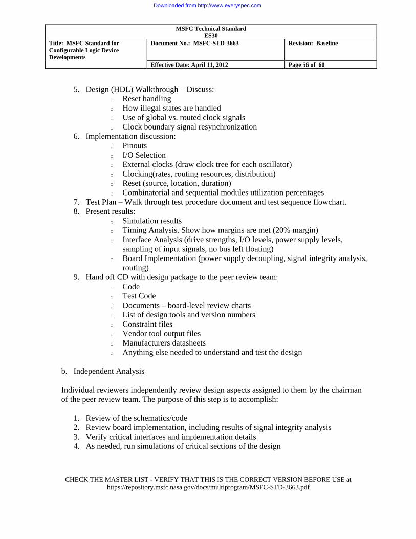
MSFC Technical Standard ES30
Title: MSFC Standard for Configurable Logic Device Developments
Document No.: MSFC-STD-3663 Revision: Baseline
Effective Date: April 11, 2012 Page 56 of 60
CHECK THE MASTER LIST - VERIFY THAT THIS IS THE CORRECT VERSION BEFORE USE at
https://repository.msfc.nasa.gov/docs/multiprogram/MSFC-STD-3663.pdf
5. Design (HDL) Walkthrough – Discuss: o Reset handling o How illegal states are handled o Use of global vs. routed clock signals o Clock boundary signal resynchronization
6. Implementation discussion: o Pinouts o I/O Selection o External clocks (draw clock tree for each oscillator) o Clocking(rates, routing resources, distribution) o Reset (source, location, duration) o Combinatorial and sequential modules utilization percentages
7. Test Plan – Walk through test procedure document and test sequence flowchart. 8. Present results:
o Simulation results o Timing Analysis. Show how margins are met (20% margin) o Interface Analysis (drive strengths, I/O levels, power supply levels,
sampling of input signals, no bus left floating) o Board Implementation (power supply decoupling, signal integrity analysis,
routing) 9. Hand off CD with design package to the peer review team:
o Code o Test Code o Documents – board-level review charts o List of design tools and version numbers o Constraint files o Vendor tool output files o Manufacturers datasheets o Anything else needed to understand and test the design
b. Independent Analysis
Individual reviewers independently review design aspects assigned to them by the chairman of the peer review team. The purpose of this step is to accomplish:
1. Review of the schematics/code 2. Review board implementation, including results of signal integrity analysis 3. Verify critical interfaces and implementation details 4. As needed, run simulations of critical sections of the design
Downloaded from http://www.everyspec.com

MSFC Technical Standard ES30
Title: MSFC Standard for Configurable Logic Device Developments
Document No.: MSFC-STD-3663 Revision: Baseline
Effective Date: April 11, 2012 Page 57 of 60
CHECK THE MASTER LIST - VERIFY THAT THIS IS THE CORRECT VERSION BEFORE USE at
https://repository.msfc.nasa.gov/docs/multiprogram/MSFC-STD-3663.pdf
5. Develop questions and comments and communicate them to the other review team members for their consideration. The communication at this point can be via email or alternate agreed upon method.
6. Each reviewer submits to the chairman his assessment of the review using the CLD Review Checklist Form provided in Appendix D
7. The chairperson ensures that all reviewers are satisfied that the flight implementation meets requirements.
c. Final Peer Review Meeting
At this meeting, held between the design team and the peer review panel members, the review chairperson communicates the following:
1. A summary of the issues that arose during review process and their resolutions 2. The results of the peer review 3. Any formally documented actions generated during the review 4. Proposed plan for the resolution of open actions
d. End of Peer Review Once all open issues are resolved, the chairperson provides:
1. A memorandum indicating that the design has been successfully reviewed and is
acceptable for flight 2. A signed copy of the CLD Review Checklist Form provided in Appendix D
e. Presentation of Peer Review Results at formal Project Reviews While each individual CLD design is typically not covered at project-level formal reviews, these reviews should present the results of the peer review process to so that questions can be answered regarding:
1. Demonstrate margins and how they are calculated 2. Results of Peer Review / issue resolution 3. Any outstanding actions 4. Peer Review Checklist certifying successful completion
Downloaded from http://www.everyspec.com
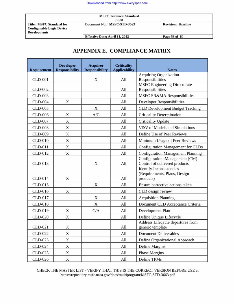
MSFC Technical Standard ES30
Title: MSFC Standard for Configurable Logic Device Developments
Document No.: MSFC-STD-3663 Revision: Baseline
Effective Date: April 11, 2012 Page 58 of 60
CHECK THE MASTER LIST - VERIFY THAT THIS IS THE CORRECT VERSION BEFORE USE at
https://repository.msfc.nasa.gov/docs/multiprogram/MSFC-STD-3663.pdf
APPENDIX E. COMPLIANCE MATRIX
Requirement Developer
Responsibility Acquirer
Responsibility Criticality
Applicability Notes
CLD-001 X All Acquiring Organization Responsibilities
CLD-002 All MSFC Engineering Directorate Responsibilities
CLD-003 All MSFC SR&MA Responsibilities CLD-004 X All Developer Responsibilities CLD-005 X All CLD Development Budget Tracking CLD-006 X A/C All Criticality Determination CLD-007 X All Criticality Update CLD-008 X All V&V of Models and Simulations CLD-009 X All Define Use of Peer Reviews CLD-010 X All Minimum Usage of Peer Reviews CLD-011 X All Configuration Management for CLDs CLD-012 X All Configuration Management Planning
CLD-013 X All Configuration :Management (CM) Control of delivered products
CLD-014 X All
Identify Inconsistencies (Requirements, Plans, Design products)
CLD-015 X All Ensure corrective actions taken CLD-016 X All CLD design review CLD-017 X All Acquisition Planning CLD-018 X All Document CLD Acceptance Criteria CLD-019 X C/A All Development Plan CLD-020 X All Define Unique Lifecycle
CLD-021 X All Address Lifecycle departures from generic template
CLD-022 X All Document Deliverables CLD-023 X All Define Organizational Approach CLD-024 X All Define Margins CLD-025 X All Phase Margins CLD-026 X All Define TPMs
Downloaded from http://www.everyspec.com
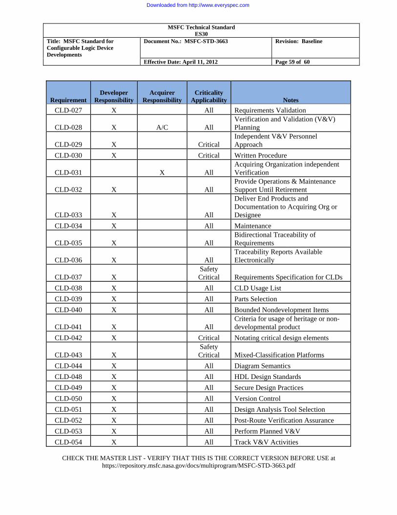
MSFC Technical Standard ES30
Title: MSFC Standard for Configurable Logic Device Developments
Document No.: MSFC-STD-3663 Revision: Baseline
Effective Date: April 11, 2012 Page 59 of 60
CHECK THE MASTER LIST - VERIFY THAT THIS IS THE CORRECT VERSION BEFORE USE at
https://repository.msfc.nasa.gov/docs/multiprogram/MSFC-STD-3663.pdf
Requirement Developer
Responsibility Acquirer
Responsibility Criticality
Applicability Notes CLD-027 X All Requirements Validation
CLD-028 X A/C All Verification and Validation (V&V) Planning
CLD-029 X Critical Independent V&V Personnel Approach
CLD-030 X Critical Written Procedure
CLD-031 X All Acquiring Organization independent Verification
CLD-032 X All Provide Operations & Maintenance Support Until Retirement
CLD-033 X All
Deliver End Products and Documentation to Acquiring Org or Designee
CLD-034 X All Maintenance
CLD-035 X All Bidirectional Traceability of Requirements
CLD-036 X All Traceability Reports Available Electronically
CLD-037 X Safety Critical Requirements Specification for CLDs
CLD-038 X All CLD Usage List CLD-039 X All Parts Selection CLD-040 X All Bounded Nondevelopment Items
CLD-041 X All Criteria for usage of heritage or non-developmental product
CLD-042 X Critical Notating critical design elements
CLD-043 X Safety Critical Mixed-Classification Platforms
CLD-044 X All Diagram Semantics CLD-048 X All HDL Design Standards CLD-049 X All Secure Design Practices CLD-050 X All Version Control CLD-051 X All Design Analysis Tool Selection CLD-052 X All Post-Route Verification Assurance CLD-053 X All Perform Planned V&V CLD-054 X All Track V&V Activities
Downloaded from http://www.everyspec.com
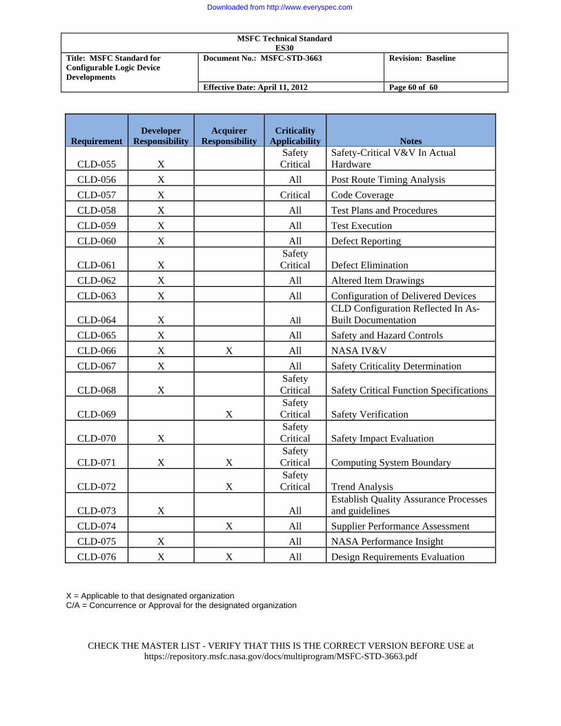
MSFC Technical Standard ES30
Title: MSFC Standard for Configurable Logic Device Developments
Document No.: MSFC-STD-3663 Revision: Baseline
Effective Date: April 11, 2012 Page 60 of 60
CHECK THE MASTER LIST - VERIFY THAT THIS IS THE CORRECT VERSION BEFORE USE at
https://repository.msfc.nasa.gov/docs/multiprogram/MSFC-STD-3663.pdf
Requirement Developer
Responsibility Acquirer
Responsibility Criticality
Applicability Notes
CLD-055 X Safety Critical
Safety-Critical V&V In Actual Hardware
CLD-056 X All Post Route Timing Analysis CLD-057 X Critical Code Coverage CLD-058 X All Test Plans and Procedures CLD-059 X All Test Execution CLD-060 X All Defect Reporting
CLD-061 X Safety Critical Defect Elimination
CLD-062 X All Altered Item Drawings CLD-063 X All Configuration of Delivered Devices
CLD-064 X All CLD Configuration Reflected In As-Built Documentation
CLD-065 X All Safety and Hazard Controls CLD-066 X X All NASA IV&V CLD-067 X All Safety Criticality Determination
CLD-068 X Safety Critical Safety Critical Function Specifications
CLD-069 X Safety Critical Safety Verification
CLD-070 X Safety Critical Safety Impact Evaluation
CLD-071 X X Safety Critical Computing System Boundary
CLD-072 X Safety Critical Trend Analysis
CLD-073 X All Establish Quality Assurance Processes and guidelines
CLD-074 X All Supplier Performance Assessment CLD-075 X All NASA Performance Insight CLD-076 X X All Design Requirements Evaluation
X = Applicable to that designated organization C/A = Concurrence or Approval for the designated organization
Downloaded from http://www.everyspec.com