
Stainless ES - Gledhill cylinders · system, any pipes that are exposed as part of the work or are...
17
Issue 4 Stainless ES Design, Installation & Servicing Instructions This manual contains important information regarding the commissioning and servicing of the product to meet the warranty conditions, and MUST be left with the product.
Transcript of Stainless ES - Gledhill cylinders · system, any pipes that are exposed as part of the work or are...

Issue 4
Stainless ESDesign, Installation & Servicing Instructions
This manual contains important information regarding thecommissioning and servicing of the product to meet the warranty conditions, and MUST be left with the product.

Page 2 Page 3
Manufacturer: Gledhill Building Products Ltd
Maximum inlet pressure toPressure reducing valve 12 barOperating pressure (PRV setting) 3 barExpansion vessel charge pressure 3 barExpansion relief valve setting 5.5 barOpening pressure of P & T Relief Valve 8 barOpening temperature of P & T Relief Valve 95°CEnergy cut-out thermostat setting 82°CMax. working pressure - Primary heat exchanger (Indirect models) 6 barImmersion heater rating 3kW, 240V AC
All cylinders are manufactured in accordance with the requirements of BS EN 12897.
The tundish must be positioned so that it is visible to the occupant and is away from electrical devices.
Components supplied with Stainless ES:• Cold water inlet PRV combination valve/expansion relief• Pressure and temperature relief valve• Dual thermostat (Control thermostat and Energy cut-out thermostat)• Energy cut-out motorised valve (indirects only)• Tundish• 3kW Immersion heater including control and cut out thermostats• Expansion vessel/mounting bracket• Technical/user product literature
In any situation where the volume of heated pipework (eg. secondary circulation pipes or manifold pipework for multiple units) exceeds 10 litres, then an additional expansion vessel must be fitted to accommodate the extra expansion volume.
The Environment
This product has been manufactured using many recyclable materials, including the approved HCFC/CFC free polyurethane foam insulation. At the end of its useful life, it should be disposed of at a Local Authority Recycling Centre, to maximise the products full environmental benefits.
Benchmark places responsibilities on both manufacturers and installers. The purpose is to ensure that customers are provided with the correct equipment for their needs, that it is installed, commissioned and serviced in accordance with the manufacturers instructions by competent persons and that it meets the requirements of the appropriate Building Regulations. The Benchmark Checklist can be used to demonstrate compliance with Building Regulations and should be provided to the customer for future reference.
Installers are required to carry out installation, commissioning and servicing work in accordance with the Benchmark Code of Practice which is available from the Heating and Hot Water Industry Council who manage and promote the Scheme. Visit www.centralheating.co.uk for more information.
For further information on the HWA Charter Statement, please refer to the HWA website hotwater.org.uk.
GLEDHILL STAINLESS ES ISSUE 4: AUGUST 2017
Technical Data
These instructions should be read in conjunction with the installation/servicing instructions issued by the manufacturer of the heat source being used.
Gledhill Stainless ES is covered by Section G3 of the Building Regulations (England and Wales) Technical Standard P3 (Scotland) and Building Regulation P5 (Northern Ireland). Compliance can be achieved via a Competent Person Self Certification Scheme or notificaton of installation to the Local Authority Building Control Department.
It must be installed by a competent person as defined by the relevant regulations. Manufacturers notes must NOT be taken as over-riding statutory obligations.
This appliance is not intended for use by persons (including children) with reduced physical, sensory or mental capabilities, or lack of experience and knowledge unless they have been given supervision or instruction concerning use of the appliance by a person responsible for their safety. Children should be supervised at all times to ensure they do not play with the appliance.
Please note: that we do not therefore accept any responsibility for matters of design selection or specification, for the effectiveness of an installation or system containing one of our products unless specifically requested to do so in writing.

Page 4 Page 5
Pro
duct
Sto
ck C
ode
Load
Pro
file
Ene
rgy
Effi
cien
cy C
lass
Hea
t Los
s
Ene
rgy
Effi
cien
cy %
Ann
ual C
onsu
mpt
ion
(kW
h/an
num
)
Ther
mos
tat
Tem
pera
ture
Set
ting
Sou
nd P
ower
Lev
el
Cap
acity
(To
tal V
olum
e)
Pre
ssur
e R
egul
ator
3 b
ar in
let
grou
p c/
w b
alan
ce c
old
supp
ly,
expa
nsio
n ve
ssel
con
nect
ion
and
expa
nsio
n va
lve
set a
t 5.5
bar
Exp
ansi
on V
esse
l siz
e.P
re-c
harg
ed to
3 b
ar
Ove
rall
Hei
ght
Ove
rall
Dia
met
er
Wei
ght E
mpt
y
Wei
ght F
ull
kW R
atin
g of
Prim
ary
Coi
l
Pre
ssur
e Lo
ss A
cros
sP
rimar
y H
eate
r C
oil
Watts kWh/24h % kWh °C db Litres bar Litres mm mm KG KG kW bar
Direct
SESINPDR090 L C 36 0.87 37% 2737 62 15 93 3 12 658 530 15 108 n/a n/a
SESINPDR120 L C 43 1.03 37% 2755 62 15 118 3 12 832 530 19 137 n/a n/a
SESINPDR150 M C 52 1.24 36% 1410 62 15 149 3 12 1012 530 22 171 n/a n/a
SESINPDR170 M C 57 1.37 36% 1417 62 15 169 3 12 1131 530 24 193 n/a n/a
SESINPDR200 L C 65 1.56 37% 2773 62 15 198 3 18 1305 530 27 225 n/a n/a
SESINPDR250 L C 79 1.89 37% 2763 62 15 248 3 18 1603 530 33 281 n/a n/a
Indirect
SESINPIN090 n/a B 36 0.87 n/a n/a n/a n/a 93 3 12 658 530 17 110 13.4 0.15
SESINPIN120 n/a B 43 1.03 n/a n/a n/a n/a 118 3 12 832 530 20 138 14.6 0.16
SESINPIN150 n/a B 52 1.24 n/a n/a n/a n/a 149 3 12 1012 530 23 172 14.0 0.14
SESINPIN170 n/a B 57 1.37 n/a n/a n/a n/a 169 3 12 1131 530 26 195 16.2 0.19
SESINPIN200 n/a C 65 1.56 n/a n/a n/a n/a 198 3 18 1305 530 29 227 16.0 0.18
SESINPIN250 n/a C 79 1.89 n/a n/a n/a n/a 248 3 18 1603 530 35 283 16.7 0.21
SESINPIN300 n/a C 92 2.20 n/a n/a n/a n/a 295 3 24 1895 530 41 336 18.3 0.23
Technical DataTechnical Data

Page 6 Page 7
Stainless ES Direct
Basic Appliance
1. Hot water draw off (22mm)2. Temperature & pressure relief valve
95°/8 bar3. Immersion heater 1¾” BSP 3kW (normally on-peak)4. Cold feed (22mm)5. Immersion heater 1¾” BSP 3kW (normally off-peak)6. Secondary return (22mm) (200, 250 and
300 litre models only)
Part G3 loose components supplied in a separate boxA. Combination inlet group incorporating:
• pressure reducing valve• strainer• check valve• balance cold take off point (22mm)• expansion relief valve (15mm)• expansion vessel hose connection
pointB. Potable expansion vessel and wall
bracketC. Tundish
Stainless ES Indirect
Basic Appliance
1. Hot water draw off (22mm)2. Temperature & pressure relief valve
95°/8 bar3. Cold feed (22mm)4. Immersion heater 1¾” BSP 3kW5. Control stat pocket (22mm)6. Primary flow (22mm)7. Primary return (22mm)8. Secondary return (22mm) (200, 250 and
300 litre models only)
Part G3 loose components supplied in a separate boxA. Combination inlet group incorporating:
• pressure reducing valve• strainer• check valve• balance cold take off point (22mm)• expansion relief valve (15mm)• expansion vessel hose connection
pointB. Potable expansion vessel and wall
bracketC. TundishD. Cylinder control thermostatE. 2 Port valve (22mm)
1
2
6
3
45
1
2
8
4
3
76
5
Both the direct and indirect cylinders are supplied with plain pipe connections suitable for use with compression fittings.
No drain valve is supplied with the product, however the draining of the unit can be achieved via the cold feed connection. For insitu cylinder draining, we would recommend a drain is fitted close to the cold feed inlet to enable maintenance work.
Technical DataTechnical Data

Page 8 Page 9
General Design Considerations
The cupboard footprint needs to be at least 650mm square. The base chosen for the cylinder should be level and capable of supporting the weight of the unit when full of water as shown in General Data. The discharge pipework for the safety valves must have a minimum fall of 1 : 200 from the unit to a safe discharge point. All exposed pipework and fittings on the cylinder should be insulated, and the unit should NOT be installed in a location where the contents could freeze.
In new systems, pipes should be insulated to comply with building regs, the maximum permissible heat loss is indicated in the table below, and labelled accordingly as follows:i. Primary circulation pipes for domestic hot water circuits should be insulated through their
length, subject only to practical constraints imposed by the need to penetrate joists and other structural elements.
ii. All pipes connected to hot water storage vessels, including the vent pipe, should be insulated for at least 1 metre from their points of connection to the cylinder (or they should be insulated up to the point where they become concealed).
In replacement systems, whenever a boiler or hot water storage vessel is replaced in an existing system, any pipes that are exposed as part of the work or are otherwise accessible should be insulated as recommended for new systems, or to some lesser standard where practical constraints dictate.
The pipe connecting the boiler flow to the appliance must not be less than 22mm copper or equivalent.
Further guidance on converting heat loss limits to insulation thickness for specific thermal conductivities is available in TIMSA “HVAC guidance for achieving compliance with Part L of the Building Regulations”.
Insulation of pipework
Pipe outside diameter Maximum heat loss
15mm 7.89W/m
22mm 9.12W/m
28mm 10.07W/m
35mm 11.08W/m
Mains Water Supply
Existing properties with a 15mm supply will be satisfactory, provided the local mains pressure is good, but should be confined to single bathroom properties. For new properties where simultaneous demand is required to more than one bathroom or a bathroom and one or more en-suites, the communication and service pipe into the dwelling should be a minimum of 22mm (usually in the form of a 25mm MDPE supply).
The optimum performance is achieved if the inlet pressure is 3 bar dynamic. However, the Stainless ES will function with lower inlet pressures, but this will reduce the performance. For optimum performance, 30L per minute incoming mains flow should be present, however the Stainless ES will work at lower flow rates, although performance will be affected.
Normally the Stainless ES provides well in excess of 40 litres/min in most conditions. Flow rates for ALL mains pressure systems are subject to district pressures and system dynamic loss. Particularly on larger properties with more than one bathroom, the pipe sizes should be calculated in accordance with BS EN 806-3:2006 and BS 8558:2011.
Pipe Layout
In all mains pressure installations it is important to remember that the incoming cold supply must be shared between all terminal fittings. It is important that a 22mm supply is brought to the appliance and a 22mm take-off is continued at least to the bath. If there are two baths, 28mm pipework should be considered. One metre of smaller diameter pipework, or flow restrictors, should be provided on the final connection to all outlets so as to balance the water available. In any event the distribution pipework should generally be in accordance with BS EN806-1 to 5.
Plastic Pipework
This appliance is suitable for use with plastic pipework as long as the material is recommended for the purpose by the manufacturer and is installed fully in accordance with their recommendations.
Secondary Hot Water Circulation
Some models are fitted with a secondary return tapping as standard. If fitted, an extra expansion vessel may be necessary. A non-return valve MUST be FITTED near the return connection. No valve or terminal fitting should be installed between the non return valve and the cylinder. (See schematic arrangement on page 13.) All pipes kept hot by the secondary circulation should be insulated.
InstallationInstallation

Page 10 Page 11
15 mmdischargepipe
Expansionrelief valve
Typical Discharge Pipe Arrangement
Dotted line showingalternative route withsingle tundish being used
600 mm max.
P & T Relief Valve
300 mmmin.
22 mm metal pipe with continuousfall up to 9m equivalent length (D2).
NOTES: The discharge will consist of scaldingwaterand steam. Asphalt, roo�ng feltand non-metallic rainwater goods maybe damaged by such discharges.
It is not acceptable to discharge straightinto a soil pipe.
Discharge below�xed grating
Fixed Grating
Trapped gully
Pressure & Temperature/expansion Relief Valve Pipework
The relief valve should be installed to discharge in accordance with G3 of the Approved Document of the Building Regulations and should be piped to where it is visible, but will not cause danger to persons or damage to materials.
The following information is taken from Approved Document G3 of the Building Regulations and is provided to assist with the design and installation of the discharge pipework. However, the information is not exhaustive and reference should always be made to Approved Document G3 of the Building Regulations. The final decision regarding any arrangements rests with Building Control and it is recommended that their advice is sought if you have any concerns regarding this aspect of the installation.
The two safety valves will only discharge water under fault conditions. When operating normally water will not be discharged.
The tundish should be vertical, located in the same space as the unvented hot water storage system and be fitted as close as possible and within 600mm of the safety device e.g. the temperature relief valve.
Worked Example
The example below is for G1/2 temperature relief valve with a discharge pipe (D2) having 4 elbows and length of 7m from the tundish to the point of discharge.
From the table below:
• Maximum resistance allowed for a straight length of 22mm copper discharge pipe (D2) from a G1/2 temperature relief valve is: 9m subtract the resistance for 4 x 22mm elbows at 0.8m each = 3.2m.
• Therefore the maximum permitted length equates to: 5.8m.• 5.8m is less than the actual length of 7m therefore calculate the next largest size.• Maximum resistance allowed for a straight length of 28mm pipe (D2) from a G1/2
temperature relief valve equates to: 14m.• As the actual length is 7m, a 28mm (D2) copper pipe will be satisfactory.
Sizing of copper discharge pipe ‘D2’ for a temperature relief valvewith a G1/2 outlet size (as supplied)
Size of discharge pipeworkMaximum length of straight pipe (no bends or elbows)
Deduct the figure below from the maximum length for each bend or elbow in
the discharge pipe
22mm Up to 9m 0.8m
28mm Up to 18m 1m
35mm Up to 27m 1.4m
The discharge pipe (D2) from the tundish should terminate in a safe place where there is no risk to persons in the vicinity of the discharge, be of metal and:
a) Be at least one pipe size larger than the nominal outlet size of the safety device unless its total equivalent hydraulic resistance exceeds that of a straight pipe 9m long i.e. discharge pipes between 9m and 18m equivalent resistance length should be at least two sizes larger than the nominal outlet size of the safety device, between 18 and 27m at least 3 sizes larger, and so on. Bends must be taken into account in calculating the flow resistance. Refer to the table and the worked example.
An alternative approach for sizing discharge pipes would be to follow BS EN 806-2:2005 Specification for design installation, testing and maintenance of services supplying water for domestic use within buildings and their curtilages.
InstallationInstallation

Page 12 Page 13
b) Have a vertical section of pipe at least 300mm long, below the tundish before any elbows or bends in the pipe work.
c) Be installed with a continuous fall.
d) It is preferable for the discharge to be visible at both the tundish and the final point of discharge but where this is not possible or practically difficult there should be clear visibility at one or other of these locations. Examples of acceptable discharge arrangements are:
1. Ideally below the fixed grating and above the water seal in a trapped gulley.
2. Downward discharges at a low level; i.e. up to 100mm above external surfaces such as car parks, hard standings, grassed areas etc are acceptable providing that where children play or otherwise come into contact with discharges, a wire cage or similar guard is positioned to prevent contact whilst maintaining visibility.
3. Discharges at a high level; e.g. into metal hopper and metal down pipe with the end of the discharge pipe clearly visible (tundish visible or not) or onto a roof capable of withstanding high temperature discharges of water and 3m from any plastic guttering systems that would collect such discharges.
4. Where a single pipe serves a number of discharges, such as in blocks of flats, the number served should be limited to not more than 6 systems so that any installation can be traced reasonably easily. The single common discharge pipe should be at least one pipe size larger than the largest individual discharge pipe to be connected. If unvented hot water storage systems are installed where discharges from safety devices may not be apparent i.e. in dwellings occupied by blind, infirm or disabled people, consideration should be given to the installation of an electronically operated device to warn when discharge takes place.
P&T Relief Valve
Tundish (15mm/22mm)
Hot Outlet
To Drain
PRV(22mm)
NRV(22mm)
StopTap
KitchenColdTap Combination
ValveLineStrainer
BalancedCold
OutletsImmersion Heater
Expansion Vessel
2233
11
BoilerReturn
BoilerFlow
2 Port Valve
SecondaryReturn Circuit
Non ReturnValve
Pump
ERV (15mm)
Combination Inlet Group
Combines elements 1, 2 and 3 below.
1. Pressure Reducing Valve - This must be fixed near the cylinder. The cold water supply to any mixer taps/showers must be taken from the cold water tapping of this valve to ensure balanced hot and cold pressures. This valve is factory set to ensure the correct operating pressure for the Stainless ES.
2. Non Return Valve - This is integral with the pressure reducing valve to prevent backflow of hot water towards cold water draw off points.
3. Cold Water Expansion Relief Valve - This safety device is preset at the factory and will relieve excess cold water pressure resulting from a fault condition.
There must be no valve on the pipe work between the expansion cylinders and the unvented cylinder which could prevent the expansion of the water contained in the unvented cylinder reaching the expansion cylinders.
InstallationInstallation
Page 14 Page 15
Pressure & Temperature Relief Valve
This safety device is also pre-set at the factory and relieves before the temperature reaches 100°C. It is also a Pressure Relief Valve, and is pre-set to 8 bar.
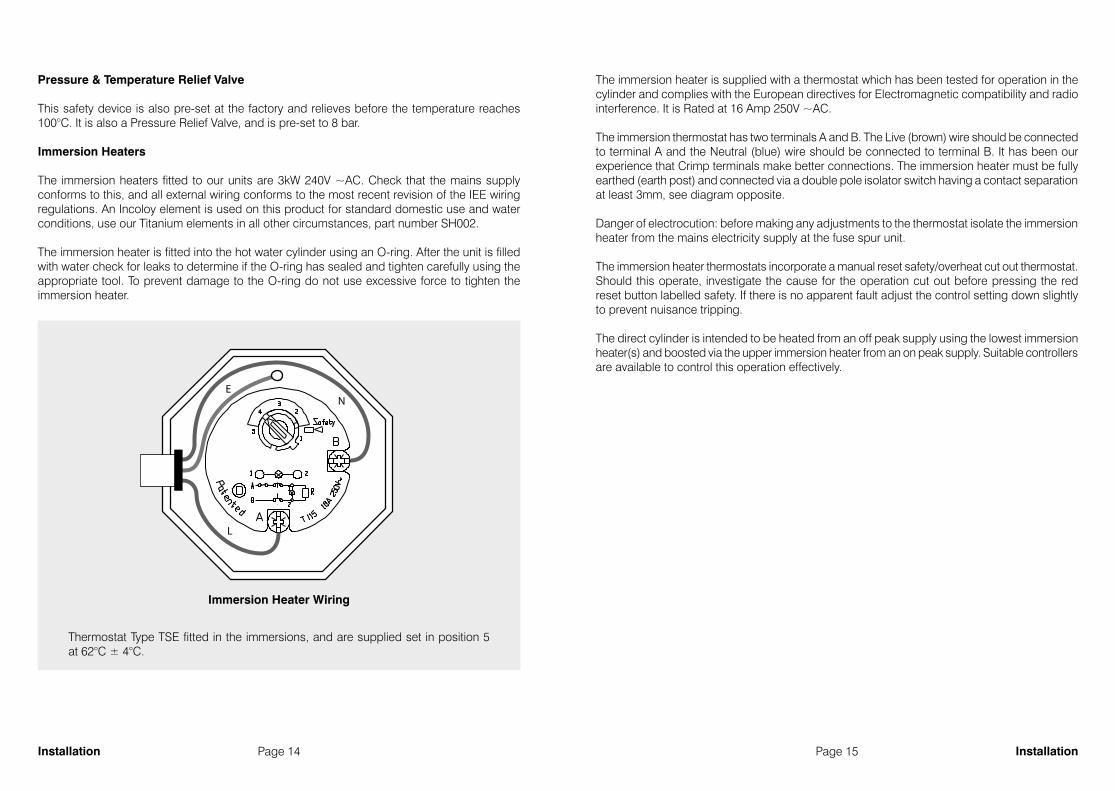
Immersion Heaters
The immersion heaters fitted to our units are 3kW 240V ~AC. Check that the mains supply conforms to this, and all external wiring conforms to the most recent revision of the IEE wiring regulations. An Incoloy element is used on this product for standard domestic use and water conditions, use our Titanium elements in all other circumstances, part number SH002.
The immersion heater is fitted into the hot water cylinder using an O-ring. After the unit is filled with water check for leaks to determine if the O-ring has sealed and tighten carefully using the appropriate tool. To prevent damage to the O-ring do not use excessive force to tighten the immersion heater.
The immersion heater is supplied with a thermostat which has been tested for operation in the cylinder and complies with the European directives for Electromagnetic compatibility and radio interference. It is Rated at 16 Amp 250V ~AC.
The immersion thermostat has two terminals A and B. The Live (brown) wire should be connected to terminal A and the Neutral (blue) wire should be connected to terminal B. It has been our experience that Crimp terminals make better connections. The immersion heater must be fully earthed (earth post) and connected via a double pole isolator switch having a contact separation at least 3mm, see diagram opposite.
Danger of electrocution: before making any adjustments to the thermostat isolate the immersion heater from the mains electricity supply at the fuse spur unit.
The immersion heater thermostats incorporate a manual reset safety/overheat cut out thermostat. Should this operate, investigate the cause for the operation cut out before pressing the red reset button labelled safety. If there is no apparent fault adjust the control setting down slightly to prevent nuisance tripping.
The direct cylinder is intended to be heated from an off peak supply using the lowest immersion heater(s) and boosted via the upper immersion heater from an on peak supply. Suitable controllers are available to control this operation effectively.
Immersion Heater Wiring
E
L
N
Thermostat Type TSE fitted in the immersions, and are supplied set in position 5 at 62°C ± 4°C.
InstallationInstallation

Page 16 Page 17
19
87
65
43
210
1112
NL
12
34
OFF
ON
OFF
ON
HW
CH
12
34
Ro
om
Th
erm
ost
atC
entr
al H
eati
ng
Co
ntr
ol
C1
C1
2
Du
al A
qau
Sta
t
Ove
rhea
t St
atC
on
tro
l Sta
t
LN
E
Mai
ns
Sup
ply
Fed
Via
Do
ub
lePo
le Is
ola
tor
230
VAC
~ 5
Am
ps
Dan
foss
WB1
2W
irin
g C
entr
e
HTG
VALV
EH
WVA
LVE
Typ
ical
sch
emat
ic w
irin
g d
iag
ram
for
an u
nve
nte
d in
stal
lati
on
The
elec
tric
al in
stal
lati
on
mu
stco
mp
ly w
ith
IEE
req
uir
emen
ts.
For e
lect
rica
l in
stal
lati
on
refe
r to
BS7
671
No
te: D
o n
ot
atte
mp
tth
e el
ectr
ical
wo
rk u
nle
ssyo
u a
re c
om
pet
ent
to c
arry
ou
t to
th
e ab
ove
sta
nd
ard
Blu
eB
lB
row
nB
r
Gre
enG
rey
Gre
en /
Yello
w
GGr
G/Y
WIR
E C
OLO
UR
LE
GE
ND
Bla
ckO
rang
eYe
llow
Whi
te
Red
B Or
Y Wh
R
Br
Bl
G/Y
Br
Br
Bl
G/Y
Or
Gr
5 A
mp
s
Br
Bl
G/Y
Br
Br
B*B
rB
lG
/Y
Br
B
Bl
Br
Br
Br
Br
Bl
BG
/YG
/YB
r*B
r
* B
lue
core
use
d
fr
om
sta
nd
ard
3 c
ore
flex
ple
ase
ensu
re y
ou
use
bro
wn
sle
evin
g a
t
bo
th te
rmin
atin
g e
nd
s
to id
enti
fy c
ore
po
ten
tial
.
3 co
re fl
ex4
core
cab
le
LN
L
L_P
SL_B
E
N
N_P
E_P
Br
Bl
G/Y
BB
rB
lG
/YB
oile
rPu
mp
ISS
UE
No
: 5A
PP
RO
VE
DD
RN
.D
ATE
07-1
2-10
N. F
ursm
an
V40
43A
TWO
PO
RT
ZON
E VA
LVE
AB
HTG
Br
Bl
G/Y
Or
Gr
V40
43A
TWO
PO
RT
ZON
E VA
LVE
AB
DH
W
Br
Bl
G/Y
Or
Gr
GA
S B
OIL
ER
Boiler Permanent Live
Boiler NeutralBoiler Earth
Boiler Switch Live Demand
Boiler Controlled Pump
Prov
ide e
xtra
core
from
term
inal
12 to
L-P
conn
ectio
n on
the b
oile
r (sh
own
dotte
d) an
d re
mov
eth
e boi
ler p
ump
link
if th
e boi
ler h
as an
inde
pend
ant
pum
p ou
tput
.
LN
E
(S-P
LAN
) WIR
ING
DIA
GR
AM
WIT
H T
WO
2 P
OR
T VA
LVES
AN
D B
OIL
ER C
ON
TRO
LLED
PU
MP
OV
ERRU
N O
PTIO
N
Br
Bl
G/Y
BB
rO
r
ELEC
TRO
NIC
S
19
87
65
43
210
1112
NL
12
34
OFF
ON
OFF
ON
HW
CH
12
34
Ro
om
Th
erm
ost
atC
entr
al H
eati
ng
Co
ntr
ol
1C
22
C1
Du
al C
ylin
der
Sta
t
Ove
rhea
t St
at
Spad
eco
nn
ecto
rsre
qu
ired
for e
arth
con
nec
tio
ns
Co
ntr
ol S
tat
LN
E
Mai
ns
Sup
ply
Fed
Via
Do
ub
lePo
le Is
ola
tor
230
VAC
~ 5
Am
ps
HTG
VALV
EH
WVA
LVE
Typ
ical
sch
emat
ic w
irin
g d
iag
ram
for
an u
nve
nte
d in
stal
lati
on
The
elec
tric
al in
stal
lati
on
mu
stco
mp
ly w
ith
IEE
req
uir
emen
ts.
For e
lect
rica
l in
stal
lati
on
refe
r to
BS7
671
No
te: D
o n
ot
atte
mp
tth
e el
ectr
ical
wo
rk u
nle
ssyo
u a
re c
om
pet
ent
to c
arry
ou
t to
th
e ab
ove
sta
nd
ard
Blu
eB
lB
row
nB
r
Gre
enG
rey
Gre
en /
Yello
w
GGr
G/Y
WIR
E C
OLO
UR
LE
GE
ND
Bla
ckO
rang
eYe
llow
Whi
te
Red
B Or
Y Wh
R
Br
Bl
G/Y
Wh
Br
Br
Bl
G/Y
Or
BG
rG
r
5 A
mp
s
Br
Bl
G/Y
Br
Br
B*B
rB
lG
/Y
Bl
Br
Br
Br
Br
Bl
BG
/YG
/YB
r
R (S
up
plie
d w
ith
sta
t)
*Br
B
* B
lue
core
use
d
fr
om
sta
nd
ard
3 c
ore
flex
ple
ase
ensu
re y
ou
use
bro
wn
sle
evin
g a
t
bo
th te
rmin
atin
g e
nd
s
to id
enti
fy c
ore
po
ten
tial
.
4 co
re c
able
4 co
re c
able
LN
L
L_P
SL_B
E
N
N_P
E_P
Br
Bl
G/Y
BB
rB
lG
/YB
oile
rPu
mp
ISS
UE
No
: 4A
PP
RO
VE
DD
RN
.D
ATE
07-1
2-10
N. F
ursm
an
AB
HTG
Wh
Bl
G/Y
Or
Gr
AB
DH
W
Br
Bl
G/Y
Or
Gr
GA
S B
OIL
ER
Boiler Permanent Live
Boiler NeutralBoiler Earth
Boiler Switch Live Demand
Boiler Controlled Pump
Prov
ide e
xtra
core
from
term
inal
12 to
L-P
conn
ectio
n on
the b
oile
r (sh
own
dotte
d) an
d re
mov
eth
e boi
ler p
ump
link
if th
e boi
ler h
as an
inde
pend
ant
pum
p ou
tput
.
LN
E
(Y-P
LAN
) WIR
ING
DIA
GR
AM
WIT
H 3
PO
RT
VALV
E/2
POR
T SA
FETY
VA
LVE
AN
D B
OIL
ER C
ON
TRO
LLED
PU
MP
OV
ERRU
N O
PTIO
N
Br
Bl
G/Y
BB
Br
Or
ELEC
TRO
NIC
S
13
V40
73A
MID
PO
SITI
ON
ZON
E VA
LVE
V40
43A
TWO
PO
RT
ZON
E VA
LVE
InstallationInstallation

Page 18 Page 19
Connections can come loose in transit, and all should be checked after first fill of the unit.
The control thermostat of the immersion heaters for direct heating of our cylinders are set at 62°C. The control thermostat for indirect heat exchanger heat up of our cylinders are usually set at between 60°C - 65°C. During commissioning the actual temperature that the cylinder reaches when the thermostat(s) operate should be tested and adjusted so that it achieves a minimum of 60°C. This temperature needs to be achieved on a regular basis in order to comply with the Legionella pasteurisation requirements.
Check the pressure on the air side of the expansion vessel = 3 bar. This must be done when the water in the cylinder is free to expand in atmospheric pressure or the cylinder and relevant pipe work is empty.
Check that all the drain cocks are closed, and open all the cold and hot water taps and other terminal fittings. Allow the system to fill with water, and to run until there is no air left in the system. Close the taps and inspect the system closely for leaks.
Manually open the Relief Valves one by one and check that water is discharged and run freely through the tundish and out at the discharge point. The pipework should accept full bore discharge without overflowing at the tundish, and the valve should seat satisfactorily.
In line with good plumbing practice, use with excessive flux should be avoided. When soldering above the cylinder, ensure flux/solder does not contaminate the cylinder below, since this can cause corrosion. Flushing should be performed as per BS EN 806:4 2010 section 6.2.
Allow the cylinder to heat to normal working temperature, then thoroughly flush the domestic hot and cold water pipework through each tap.
NOTE: If this appliance is to be installed in other than a single domestic dwelling ie. in an apartment block or student flats etc., the hot and cold water system will need to be disinfected in accordance with BS EB 806:4 2010 section 6.3 and the Water Regulations.
Because the Stainless ES appliance is stainless steel, the use of chlorine as the disinfection agent can cause damage unless the appliance is adequately flushed and refilled with the mains water immediately on completion of the disinfection procedure. Damage caused through a failure to do this adequately will not be covered by the warranty. For the reasons mentioned, we recommend the use of a non chlorine based disinfectant such as Fernox LP Sterox as manufactured by Cookson Electronics when carrying out disinfection of systems incorporating these appliances.
Remove the filter from the combination inlet group clean and replace. Refill the system and open all hot taps until there is no air in the pipe work. ENSURE CYLINDER IS DRAINED PRIOR TO CHECKING OR REMOVING FILTER FROM THE COMBINATION INLET GROUP.
Please note a drain valve is not supplied with the cylinder.
IMPORTANT - DRAIN DOWN PROCEDURE
1 Switch off both the boiler and the immersion heater
2 Open the nearest hot tap and run all hot water until cold, then close it
3 Close the incoming cold main at the stop tap
4 Hold open the pressure and temperature relief valve until water stops discharging into the tundish and keep it open
5 Open the cold taps starting from the highest point and working down to the lowest tap, leaving them open
6 When the cold taps have stopped draining, open the hot taps starting from the highest and working down to the lowest tap
7 Open the drain cock and ensure the pressure and temperature relief valve is held open until the cylinder is empty
Allow the cylinder to heat to normal working temperature with whatever heat source is to be used, and check again for leaks. The pressure relief valve or the P&T valve should not operate during the heating cycle. If the P&T valve operates before the pressure relief valve due to high pressure, check that the inlet control group is fitted correctly, and that no valves are fitted between the cylinder and the expansion vessel
The boiler/heating systems should be filled and commissioned in accordance with good practice following the guidance in BS 7593:2006/the boiler manufacturers instructions. This includes adequately flushing the system to remove any debris that may have been introduced during installation/maintenance.
Scale
In hard water areas it is recommended that an in-line scale inhibitor is fitted. Reducing the temperature of the stored water will reduce the rate at which scale forms. If the recovery rate is badly affected, this is an indication that scaling may have occurred. In this event, follow the procedures as recommended by a reputable Water Treatment Company.
NOTE
At the time of commissioning, complete all relevant sections of the Benchmark Checklist located on the inside back pages of this document. This must be completed during commissioning and left with the product to meet the Warranty conditions.
CommissioningCommissioning

Page 20 Page 21
Your Stainless ES unvented cylinder is automatic in normal use, but requires routine maintenance which is normally carried out at least annually along with the boiler service. The maintenance must be carried out by a suitably competent tradesperson who is qualified to work on unvented cylinders. The checks/work needed are listed in the maintenance part of these Instructions.
The control thermostat of the immersion heaters for direct heating of our cylinders are set at 62°C. The control thermostat for indirect heat exchanger heat up of our cylinders are usually set at between 60°C - 65°C. During commissioning the actual temperature that the cylinder reaches when the thermostat(s) operate should be tested and adjusted so that it achieves a minimum of 60°C. This temperature needs to be achieved on a regular basis in order to comply with the Legionella pasteurisation requirements.
When initially opening the taps, a small surge in flow may be experienced, which disappears as the pressure in the system stabilises. This is quite normal with these types of systems and does not indicate a fault.
In some areas the water will initially appear cloudy, but will quickly clear when left to stand. This is nothing to be concerned about and is due to aeration of the water.
WARNING - If water is seen flowing through the tundish, this indicates a fault condition which needs action.
If the discharge is hot and continuous, turn the boiler and/or the immersion heaters off, but do not turn off the cold water to the appliance until the discharge is cold.
Note: The discharge may stop by itself as the discharge cools.
If the discharge is cold and intermittent, no immediate action is needed but this indicates a problem with the expansion vessel.
However, in both cases you must call the registered installer / a suitably qualified, competent tradesperson, advise them that you have an unvented cylinder and request a maintenance visit.
DO NOT, at any time, tamper in any way with the safety valves or overheat thermostats/wiring.
NOTE
At the time of commissioning, complete all relevant sections of the Benchmark Checklist located on the inside back pages of this document. This must be completed during commissioning and left with the product to meet the Warranty conditions.
The Registered Installer is responsible for the safe installation and operation of the system. The installer must also make his customer aware that periodic maintenance of the equipment is essential for safety.
Maintenance periods will vary for many reasons. Gledhill Building Products Ltd recommend a maximum of 12 months to coincide with boiler maintenance. Experience of local water conditions may indicate that more frequent maintenance is desirable, eg, when water is particularly hard, scale-forming or where the water supply contains a high proportion of solids, eg, sand. Maintenance must include, but not limited to, the following:
1. Turn the mains water off, remove and clean the strainer element in in the Pressure Reducing Valve.
2. Manually check the operation of the temperature relief valve.3. Manually check the operation of the expansion relief valve.4. Check discharge pipes from temperature and expansion relief valves are free from obstruction
and blockage and are not passing any water.5. Check that water pressure downstream of combination valve is 3 bar in static condition.6. Check operation of motorised valve.7. Check the pressure on the air side of the expansion vessel. This must be done when the
volume in the cylinders is cold.8. Re-fill the system and ensure that all relief valves have re-seated.9. Check and advise the householder not to place any clothing or other combustible materials
against or on top of this appliance.10. On completion of the work, fill in the Benchmark Service Record towards the back of this
manual.
After servicing, complete the relevant Service Interval Record section of the Benchmark Checklist located on the inside back pages of this document.
IMPORTANT NOTE
When draining down the appliance for any reason, the instructions provided in the Commissioning Section (Page 19) MUST be followed to prevent potential damage to the cylinder.
Servicing and MaintenanceUser Instructions
Page 22 Page 23
General
No water at the tap. Check that the mains water supply is turned ON. Check the line strainer is not blocked. Check that the combination valve has been fitted so that water is flowing in the correct direction.
If the water at the tap is cold, ensure that the boiler has been switched ON and is working correctly. Check that there are no air locks in the primary system. ISOLATE THE UNIT AT THE MAINS ELECTRIC SUPPLY AND THEN CHECK THE FOLLOWING:i. The cylinder thermostatii. The thermal cut-out, which can be re-set by pushing the red buttoniii. The motorised valveiv. The boiler thermostatv. The boiler thermostat cut-out (if fitted)
ANY ENERGY CUT-OUT MUST NEVER BE BY-PASSED UNDER ANY CIRCUMSTANCES.
If the units are not getting hot and the heat source is electrical, ensure that the immersion heaters are isolated from the mains before re-setting the energy cut-out. If the immersion heater(s) need replacing this should be done with the units supplied from Gledhill Building Products Limited. Same day despatch by Gledhill Spares to approved installers can be arranged by telephoning 01253 474412.
Discharge From Relief Valves
If cold water is discharging from the expansion relief valve into the tundish check the pressure on the expansion vessel when cold and recharge if necessary.
If the fault continues and the problem cannot be stopped by operating the control a few times then either the Pressure Reducing Valve or the Relief Valve may be at fault. If the cold water pressure is too high, this would suggest that the Pressure Reducing Valve is at fault and the Gledhill approved replacement should be fitted. If the pressure is correct then the Relief Valve will require replacing with a Gledhill approved component.
See Commissioning for drain down procedure.
If there is an overheat fault and very hot water is being discharged, turn off the heat source, but not the water supply.
When the supply is cool, check thermostats and energy cut-outs in the boiler and immersion heaters and replace the faulty component with a unit supplied by Gledhill and check that it works correctly before returning the system to full operation.
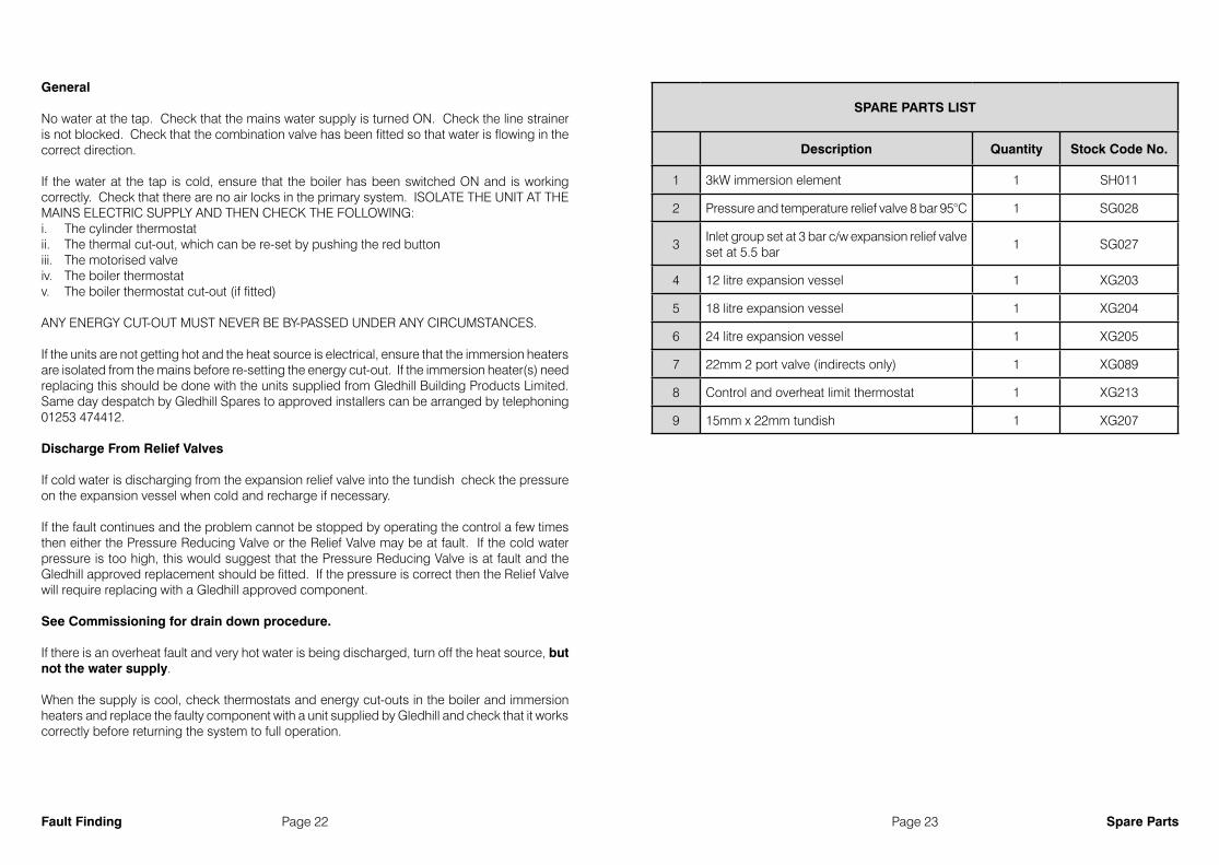
SPARE PARTS LIST
Description Quantity Stock Code No.
1 3kW immersion element 1 SH011
2 Pressure and temperature relief valve 8 bar 95°C 1 SG028
3Inlet group set at 3 bar c/w expansion relief valve set at 5.5 bar
1 SG027
4 12 litre expansion vessel 1 XG203
5 18 litre expansion vessel 1 XG204
6 24 litre expansion vessel 1 XG205
7 22mm 2 port valve (indirects only) 1 XG089
8 Control and overheat limit thermostat 1 XG213
9 15mm x 22mm tundish 1 XG207
Spare PartsFault Finding

Page 24 Page 25 WarrantyWarranty
Gledhill Building Products guarantees the Stainless ES cylinder and components against material defect or manufacturing fault for a period of two years from the date of purchase. The two year warranty on the stainless steel inner cylinder will be extended to twenty five years in domestic properties on the registration of the cylinder (see documentation enclosed with the unit).
The above product guarantees are valid provided:
• It has been installed by a competent installer in accordance with the instructions detailed in our installation manual and all relevant Codes of Practice and Regulations in force at the time of installation.
• No factory fitted parts have been removed for unauthorised repair or replacement and the product has not been modified - other than by Gledhill.
• Any replacement parts used should be authorised, approved Gledhill spare parts. • The cylinder has only been used for the storage of potable water supplied form the public
mains (-max 200mg/litre chloride).• It has not been subject to wrong or improper use, left uncared for, or subjected to scale or
frost damage. • The unit has been serviced annually by a competent, licenced engineer in accordance
with the requirement set out in the manual. • The Benchmark TM Commissioning Checklist Service Record included in our manual has
been completed and updated after each annual service. • Any disinfection has been carried out strictly in accordance with BS6700.• For heavy use installation where constant usage / reheat is required titanium immersion
heaters should be fitted. • The registration document enclosed with the unit is completed and returned
within 60 days of purchase by the owner. Evidence of purchase and date of supply must be submitted upon making a claim.
Guidance in the event of a problem
If you have a problem in the first year, please contact the plumber who fitted the unit. After the first year, you should contact the plumber who carries out the annual servicing for you.
Action in the event of component failure within warranty period
Failed components should be returned via the local authorised supplier. A nominal charge of £30 will be made which is refunded in full by Gledhill on receipt of the original part and proof of purchase.
Action in the event of inner vessel cylinder failure within warranty period
Since the full diagnosis of cause of failure is usually only possible with a laboratory test environment where a product can be fully assessed and tested, we will require the return of a cylinder which develops a leak for inspection. Providing our expert examination confirms a manufacturing fault or defect, credit will then be raised against the cost of the original cylinder.
Please note that a copy of the completed annual service record and commissioning checklist should be submitted with any claim.
As a HWA Charter Member we endeavour to provide consumers quality assurance, product satisfaction, and confidence in Gledhill, that we will deliver a service beyond just supplying the product.

Page 26 Page 27
profits, business revenue, goodwill or anticipated savings (ii) damages in respect of special indirect or consequential loss or damage (other than death, personal
injury and damage to tangible property) (iii) any claim made against the purchaser by any other party (save as expressly provided in paragraph (b)
above) (e) Except in respect of our liability referred to in paragraph (a) above no claim may be made or action brought
(whether in contract or in tort including negligence) by the purchaser in respect of any goods supplied by us more than one year after the date of the invoice for the relevant goods.
(f) Without prejudice to any other term we shall not be liable for any water damage caused directly or indirectly as a result of any leak or other defect in the goods. We cannot control the conditions of use of the goods or the time or manner or location in which they will be installed and the purchaser agrees to be fully responsible for testing and checking all works which include the goods at all relevant times (up to, including and after commissioning) and for taking all necessary steps to identify any leaks and prevent any damage being caused thereby.
(g) Nothing in these Conditions shall confer on the purchaser any rights or remedies to which the purchaser would not otherwise be legally entitled
10. LOSS OR INJURY Notwithstanding any other provision contained herein the purchaser’s hereby agree to fully indemnify us against any damages losses costs claims or expenses incurred by us in respect of any claim brought against us by any third party for:-(a) any loss injury or damage wholly or partly caused by any goods supplied by us or their use.(b) any loss injury or damage wholly or partly caused by the defective installation or substandard workmanship or
materials used in the installation of any goods supplied by us.(c) any loss injury or damage in any way connected with the performance of this contract.(d) any loss resulting from any failure by the purchaser to comply with its obligations under these terms as to
install and/or check works correctly.PROVIDED that this paragraph will not require the purchaser to indemnify us against any liability for our own acts of negligence or those of our employees agents or sub-contractorsFURTHER in the case of goods supplied by us which are re-sold and installed by a third party by the purchaser it will be the sole responsibility of the purchaser to test the goods immediately after their installation to ensure that inter alia they are correctly installed and in proper working order free from leaks and are not likely to cause any loss injury or damage to any person or property.11. VARIATION OF WARRANTY AND EXCLUSIONShould our warranty and exclusion be unacceptable we are prepared to negotiate for variation in their terms but only on the basis of an increase in the price to allow for any additional liability or risk which may result from the variation. Purchasers are advised to insure against any risk or liability which they may incur and which is not covered by our warranty.12. ADVICEAny advice or assistance given by the Company is provided without charge and is in good faith without undertaking, representation or warranty, and we will not accept any liability, whether consequential or compensatory, for advice or assistance given.13. RISK AND RETENTION OF TITLE(a) goods supplied by us shall be at the Purchaser’s risk immediately upon delivery to the Purchaser or into
custody on the Purchaser’s behalf or to the Purchaser’s Order. The Purchaser shall effect adequate insurance of the goods against all risks to the full invoice value of the goods, such insurance to be effective from the time of delivery until property in the goods shall pass to the Purchaser as hereinafter provided.
(b) property in the goods supplied hereunder will pass to the Purchaser when full payment has been made by the Purchaser to us for :-
(i) the goods of the subject of this contract. (ii) all other goods the subject to of any other contract between the Purchaser and us which, at the time of
payment of the full price of the goods sold under this contract, have been delivered to the Purchaser but not paid for in full.
(c) until property in the goods supplied hereunder passes to the Purchaser in accordance with paragraph (2) above.
(i) the Purchaser shall hold the goods in a fiduciary capacity for us and shall store the same separately from any other goods in the Purchaser’s possession and in a manner which enables them to be identified as our goods.
(ii) the Purchaser shall immediately return the goods to us should our authorised representative so request. All the necessary incidents associated with a fiduciary relationship shall apply.
(d) the Purchaser’s right to possess the goods shall cease forthwith upon the happening of any of the following events, namely :-
(i) if the Purchaser fails to make payment in full for the goods within the time stipulated in clause 4 hereof. (ii) if the Purchaser, not being a company, commits any act of bankruptcy, makes a proposal to his or her
creditors for a compromise or does anything which would entitle a petition for a Bankruptcy Order to be presented.
(iii) if the Purchaser, being a company, does anything or fails to do anything which would entitle an administrator or an administrative receiver or a receiver to take possession of any assets or which would entitle any person to present a petition for winding up or to apply for an administration order.
(e) the Purchaser hereby grants to us an irrevocable licence to enter at any time any vehicle or premises owned or occupied by the Purchaser or in the possession of the Purchaser for the purposes of repossessing and recovering any such goods the property in which has remained in us under paragraph (2) above. We shall not be responsible for and the Purchaser will indemnify us against liability in respect of damage caused to any vehicle or premises in such repossession and removal being damaged which it was not reasonably practicable to avoid.
(f) notwithstanding paragraph (3) hereof and subject to paragraph (7) hereof, the Purchaser shall be permitted to sell the goods to third parties in the normal course of business. In this respect the Purchaser shall act in the capacity of our commission agent and the proceeds of such sale :-
(i) shall be held in trust for us in a manner which enables such proceeds to be identified as such, and: (ii) shall not be mixed with other monies nor paid into an overdrawn bank account.
We, as principal, shall remunerate the Purchaser as commission agent a commission depending upon the surplus which the Purchaser can obtain over and above the sum, stipulated in this contract of supply which will satisfy us.
(g) in the event that the Purchaser shall sell any of the goods pursuant to clause (6) hereof, the Purchaser shall
forthwith inform us in writing of such sale and of the identity and address of the third party to whom the goods have been sold.
(h) if, before property in the goods passes to the Purchaser under paragraph (2) above the goods are or become affixed to any land or building owned by the Purchaser it is hereby agreed and declared that such affixation shall not have the effect of passing property in the goods to the Purchaser. Furthermore if, before property in the goods shall pass to the Purchaser under paragraph (2) hereof, the goods are or become affixed to any land or building (whether or not owned by the Purchaser), the Purchaser shall:-
(i) ensure that the goods are capable of being removed without material injury to such land or building.
(ii) take all necessary steps to prevent title to the goods from passing to the landlord of such land or building.
(iii) forthwith inform us in writing of such affixation and of the address of the land or building concerned.
The Purchaser warrants to repair and make good any damage caused by the affixation of the goods to or their removal from any land or building and to indemnify us against all loss damage or liability we may incur or sustain as a result of affixation or removal.
(i) in the event that, before property in the goods has passed to the Purchaser under paragraph (2) hereof, the goods or any of them are lost, stolen, damaged or destroyed :-
(ii) the Purchaser shall forthwith inform us in writing of the fact and circumstances of such loss, theft, damage or destruction.
(iii) the Purchaser shall assign to us the benefit of any insurance claim in respect of the goods so lost, stolen, damaged or destroyed.
14. NON-PAYMENTIf the Purchaser shall fail to make full payment for the goods supplied hereunder within the time stipulated in clause 4 hereof or be in default of payment for any other reason then, without prejudice to any of our other rights hereunder, we shall be entitled to stop all deliveries of goods and materials to the Purchaser, including deliveries or further deliveries of goods under this contract. In addition we shall be entitled to terminate all outstanding orders.15. VALUE ADDED TAXAll prices quoted are exclusive of Value Added Tax which will be charged at the rate ruling at the date of despatch of invoice.16. TRADE SALES ONLYWe are only prepared to deal with those who are not consumers within the terms of the Unfair Contract Terms Act 1977, the Sale of Goods Act 1979 and the Supply of Goods and Services Act 1982. Accordingly any person who purchases from us shall be deemed to have represented that he is not a consumer by so purchasing.17. JURISDICTIONThe agreement is subject to English law for products delivered in England and Scottish law for products delivered in Scotland and any dispute hereunder shall be settled in accordance therewith dependent upon the location.18. PRODUCT DEVELOPMENTGledhill have a policy of continuous product development and may introduce product modifications from time to time.
Gledhill (Building Products) Ltd AMD. SEPTEMBER 2017
CONDITIONS OF SALE & GUARANTEE TERMS
1. Gledhill (Building Products) Ltd (“We” or “Gledhills”) only do business upon the Conditions which appear below and no other. Unless we so agree in writing these Conditions shall apply in full to any supply of goods by us to the exclusion of any Conditions or terms sought to be imposed by any purchaser. These Conditions of Sale and Warranty Terms override those which are contained on the Invoice Forms and all Sales are now subject to these Conditions of Sale and Warranty terms only.2. PRICEOnce an order or call off has been accepted the price will be held for three months but if delivery is extended beyond that period at the customer’s request, then we reserve the right to amend the price when necessary. The company reviews its pricing annually to adjust for changes in our cost base. We reserve the right to alter prices at any time for severe movements in raw materials (mainly copper and steel). If there is to be a change we will give customers at least four weeks notice but anything delivered after that date will be at the revised price. An order may not be cancelled or varied after acceptance without the written consent of the company. Such cancellation or variation shall be subject to such reasonable charges as may be appropriate.3. SPECIFICATIONThe goods are supplied in accordance with the Specifications (if any) submitted to the Purchaser and any additions and alterations shall be the subject of an extra charge. Any goods not so specified shall be in accordance with our printed literature or the literature of any of our component suppliers (subject to any modifications made since publication). If we adopt any changes in construction or design of the goods, or in the specification printed in our literature, the Purchaser shall accept the goods so changed in fulfilment of the order.4. PAYMENTThe buyer shall make payment in full within thirty days from the end of the month in which the invoice is dated. If we receive payment in full on or before the due date we will allow an appropriate settlement discount except where we have quoted a special net price. If payment is not received in full on or before the due date we shall be entitled in addition to the invoice price to:(i) payment of a sum equal to any increase in the copper price supplement applicable to the particular goods sold
between the date of receipt of order and the date of receipt of payment in full; and (ii) interest on any part of the invoice price unpaid after the due date at the rate of 3% per annum over the base
rate for the time being of HSBC Bank plc.5. TIMEWe give estimates of delivery dates in good faith and time of delivery is not nor shall be made of the essence of any contract nor shall we be liable for any loss or damage occasioned by delay in delivery.6. DELIVERYWe deliver free normally by our own vehicles within 25 miles of any of our manufacturing depots. Delivery to any place more than 25 miles from one of our manufacturing depots may be subject to our quoted delivery charges. We reserve the right to make delivery of goods contained in one order by more than one consignment and at different times. Where a period is agreed for delivery and such period is not extended by our Agreement, the Purchaser shall take delivery within that period. If the Purchaser fails to take delivery, we shall be entitled at the Purchaser’s risk and expense to store the goods at the Purchaser’s premises or elsewhere and to demand payment as if they had been despatched. Off loading at point of delivery shall be the responsibility of and be undertaken by the Purchaser.7. SHORTAGES OR DAMAGEGoods must be inspected before signature of delivery note and any damage, shortage or discrepancy noted on the delivery note and the goods returned on the same vehicle. The buyer must also give us immediate written notice of the damage, shortage or discrepancy so that we may prompt investigation.8. RETURN OF GOODSGoods may not be returned to the Company except by prior written permission of an authorised officer of the Company and such return shall be subject to payment by the Purchaser of handling and re-stocking charges, transport and all other costs incurred by the Company.9. COMPANY LIABILITY AND GUARANTEE9.1. Subject to the terms of these Conditions of Sale and Guarantee Terms Gledhills provide Guarantees in respect
of specific products as set out in this clause.9.2. Each Guarantee is strictly conditional upon the following:-9.2.1. Complaints must be given to us immediately, before any action is taken, as responsibility cannot be accepted
if repairs or renewals are attempted on site without our written approval.9.2.2. The unit has been installed in accordance with our installation and service instructions and all relevant codes
of practice and regulations in force at the time of installation.9.2.3. All necessary inlet controls and safety valves have been fitted correctly. 9.2.4. The unit has only been used for the storage of potable water supplied from the public mains. The water quality
shall be in accordance with European Council Directive 98/83 EC, or revised version at the date of installation, and is not fed with water from a private supply. Particular:
Chloride content: Max. 200 mg/l Sulphate content: Max. 200 mg/l Combination chloride/sulphate: Max. 300 mg/l (in total)9.2.5 Where appropriate the unit has been regularly maintained as detailed in the installation and service instructions 9.2.6. Defects caused by corrosion or scale deposits are not covered by any Guarantee.9.2.7. Where we agree to rectify any defect we reserve the right to undertake the work on our own premises.9.2.8. We will not accept any labour charges associated with replacing the unit or parts for any of the following
products listed.9.2.9. If the newly fitted water heater is not in regular use then it must be flushed through with fresh water for at least
15 minutes. Open at least one hot water tap once per week, during a period of at least 4 weeks.9.3. Guarantees are provided in respect of specified goods supplied by Gledhills as follows:-
(a) Domestic and Commercial Open Vented Cylinders and Tanks. The storage vessel is guaranteed for ten years and if it proves to be defective either in materials or workmanship,
we reserve the right to either repair or supply replacement at our option with the closest substitute in the case of any obsolete product to any address in England, Wales and Scotland (excluding all Scottish Islands).(b) Domestic Mains Fed Products [Primary Stores]
The storage vessel is guaranteed for five years and if it or any integral pipework as part of the storage vessel assembly proves to be defective either in materials or workmanship, we reserve the right to either repair or supply replacement at our option with the closest substitute in the case of any obsolete product to any address in England, Wales and Scotland (excluding all Scottish Islands).
(c) Unvented Cylinders Gledhill guarantee the components including controls, valves and electrical parts for two years from the date
of purchase. IT SHOULD BE NOTED THAT THE FACTORY FITTED TEMPERATURE AND PRESSURE RELIEF VALVE MUST NOT BE REMOVED OR ALTERED IN ANY WAY OR THE GUARANTEE WILL NOT BE VALID. GLEDHILL WILL
NOT BE RESPONSIBLE FOR ANY CONSEQUENTIAL LOSS OR DAMAGE HOWEVER IT IS CAUSED.
The guarantee for the stainless steel vessel is for twenty five years against material defect or manufacturing faults if the original unit is returned to us AND PROVIDED THAT:
(i) It has not been modified, other than by Gledhill. (ii) It has not been subjected to wrong or improper
use or left uncared for. (iii) It has only been used for the storage of potable
water supplied from the public mains, max 200mg/litre chloride.
(iv) It has not been subjected to frost damage. (v) The benchmark service record is completed after
each annual service. (vi) The unit has been serviced annually. (vii) Any disinfection has been carried out strictly in
accordance with BS6700. If the stainless steel vessel proves to be defective
either in materials or workmanship we reserve the right to either repair or supply replacement at our option with the closest substitute in the case of any obsolete product to any address in England, Wales and Scotland (excluding all Scottish Islands).
ACTION IN THE EVENT OF FAILURE We will require the return of a cylinder which develops
a leak for inspection. If our examination confirms a failure then an appropriate level of credit against the cost of the original cylinder will be issued in line with the terms of our warranty.Please note:
- Installation must have been carried out by a licensed specialized company (heating contractor or plumber) following the version of installation instructions in force.
- Gledhill or its representative was given the opportunity to check complaints on site immediately after any defect occurred.
- Confirmation exists that the system was commissioned properly and that the system was checked and maintenance was performed annually by a specialised company licensed for this purpose.
(d) Components of our products other than Storage Vessels and Integral Pipework.
We will either extend to the purchaser the same terms of warranty as we are given by the manufacturer of the component or if the manufacturer does not give any warranty, replace free of charge any component which becomes defective within two years after the date of the delivery by us and is returned to us at the purchaser’s expense but we shall not meet the cost of removal or shipping or return of the component or any other cost charges or damages incurred by the purchaser.
9.4. 9.4.1. In respect of goods supplied by us and in respect of
any installation work carried out by or on our behalf, our entire liability and the purchaser’s sole remedies (subject to the Guarantees) shall be as follows:-
(a) We accept liability for death or personal injury to the extent that it results from our negligence or that of our employees
(b) Subject to the other provisions of this clause 9 we accept liability for direct physical damage to tangible property to the extent that such damage is caused by our negligence or that of our employees, agents or subcontractors.
(c) Our total liability to the purchaser over and above any liability to replace under the Guarantees (whether in contract or in tort including negligence) in respect of any one cause of loss or damage claimed to result from any breach of our obligations hereunder, shall be limited to actual money damages which shall not exceed £20,000 provided that such monetary limit shall not apply to any liability on the part of ourselves referred to in paragraph (a) above
(d) Except as provided in paragraph (a) above but otherwise not withstanding any provision herein contained in no event shall we be liable for the following loss or damage howsoever caused and even if foreseeable by us or in our contemplation:-
(i) economic loss which shall include loss of
Terms and ConditionsTerms and Conditions

Page 28 Page 29
This
Com
mis
sion
ing
Che
cklis
t is
to b
e co
mpl
eted
in fu
ll by
the
com
pete
nt p
erso
n w
ho c
omm
issi
oned
the
stor
age
syst
em a
s a
mea
ns o
f de
mon
stra
ting
com
plia
nce
with
the
appr
opria
te B
uild
ing
Reg
ulat
ions
and
then
han
ded
to th
e cu
stom
er to
kee
p fo
r fut
ure
refe
renc
e.
Failu
re to
inst
all a
nd c
omm
issi
on th
is e
quip
men
t to
the
man
ufac
ture
r’s in
stru
ctio
ns m
ay in
valid
ate
the
war
rant
y bu
t doe
s no
t affe
ct s
tatu
tory
righ
ts.
MA
INS
PRES
SUR
E H
OT
WAT
ER S
TOR
AG
E SY
STEM
CO
MM
ISSI
ON
ING
CH
ECK
LIST
Cus
tom
er n
ame:
Tele
phon
e nu
mbe
r:
Add
ress
:
Cyl
inde
r Mak
e an
d M
odel
Cyl
inde
r Ser
ial N
umbe
r
Com
mis
sion
ed b
y (P
RIN
T N
AM
E):
Reg
iste
red
Ope
rativ
e ID
Num
ber
Com
pany
nam
e:Te
leph
one
num
ber:
Com
pany
add
ress
:
Com
mis
sion
ing
date
:
To b
e co
mpl
eted
by
the
cust
omer
on
rece
ipt o
f a B
uild
ing
Reg
ulat
ions
Com
plia
nce
Cer
tifica
te*:
Bui
ldin
g R
egul
atio
ns N
otifi
catio
n N
umbe
r (if
appl
icab
le)
ALL
SYS
TEM
S PR
IMA
RY S
ETTI
NG
S (in
dire
ct h
eatin
g on
ly)
Is th
e pr
imar
y ci
rcui
t a s
eale
d or
ope
n ve
nted
sys
tem
?S
eale
dO
pen
Wha
t is
the
max
imum
prim
ary
flow
tem
pera
ture
?°C
ALL
SYS
TEM
S
Wha
t is
the
inco
min
g st
atic
col
d w
ater
pre
ssur
e at
the
inle
t to
the
syst
em?
bar
Has
a s
train
er b
een
clea
ned
of in
stal
latio
n de
bris
(if fi
tted)
?Ye
sN
o
Is th
e in
stal
latio
n in
a h
ard
wat
er a
rea
(abo
ve 2
00pp
m)?
Yes
No
If ye
s, h
as a
wat
er s
cale
redu
cer b
een
fitte
d?Ye
sN
o
Wha
t typ
e of
sca
le re
duce
r has
bee
n fit
ted?
Wha
t is
the
hot w
ater
ther
mos
tat s
et te
mpe
ratu
re?
°C
Wha
t is
the
max
imum
hot
wat
er fl
ow ra
te a
t set
ther
mos
tat t
empe
ratu
re (m
easu
red
at h
igh
flow
out
let)?
I/min
Tim
e an
d te
mpe
ratu
re c
ontro
ls h
ave
been
fitte
d in
com
plia
nce
with
Par
t L o
f the
Bui
ldin
g R
egul
atio
ns?
Yes
Type
of c
ontro
l sys
tem
(if a
pplic
able
)Y
Pla
nS
Pla
nO
ther
Is th
e cy
linde
r sol
ar (o
r oth
er re
new
able
) com
patib
le?
Yes
No
Wha
t is
the
hot w
ater
tem
pera
ture
at t
he n
eare
st o
utle
t?°C
All
appr
opria
te p
ipes
hav
e be
en in
sula
ted
up to
1 m
etre
or t
he p
oint
whe
re th
ey b
ecom
e co
ncea
led
Yes
UN
VEN
TED
SYS
TEM
S O
NLY
Whe
re is
the
pres
sure
redu
cing
val
ve s
ituat
ed (i
f fitte
d)?
Wha
t is
the
pres
sure
redu
cing
val
ve s
ettin
g?ba
r
Has
a c
ombi
ned
tem
pera
ture
and
pre
ssur
e re
lief v
alve
and
exp
ansi
on v
alve
bee
n fit
ted
and
disc
harg
e te
sted
?Ye
sN
o
The
tund
ish
and
disc
harg
e pi
pew
ork
have
bee
n co
nnec
ted
and
term
inat
ed to
Par
t G o
f the
Bui
ldin
g R
egul
atio
nsYe
s
Are
all
ener
gy s
ourc
es fi
tted
with
a c
ut o
ut d
evic
e?Ye
sN
o
Has
the
expa
nsio
n ve
ssel
or i
nter
nal a
ir sp
ace
been
che
cked
?Ye
sN
o
THER
MA
L ST
OR
ES O
NLY
Wha
t sto
re te
mpe
ratu
re is
ach
ieva
ble?
°C
Wha
t is
the
max
imum
hot
wat
er te
mpe
ratu
re?
°C
ALL
INST
ALL
ATIO
NS
The
hot w
ater
sys
tem
com
plie
s w
ith th
e ap
prop
riate
Bui
ldin
g R
egul
atio
nsYe
s
The
syst
em h
as b
een
inst
alle
d an
d co
mm
issi
oned
in a
ccor
danc
e w
ith th
e m
anuf
actu
rer’s
inst
ruct
ions
Yes
The
syst
em c
ontro
ls h
ave
been
dem
onst
rate
d to
and
und
erst
ood
by th
e cu
stom
erYe
s
The
man
ufac
ture
r’s li
tera
ture
, inc
ludi
ng B
ench
mar
k C
heck
list a
nd S
ervi
ce R
ecor
d, h
as b
een
expl
aine
d an
d le
ft w
ith th
e cu
stom
erYe
s
Com
mis
sion
ing
Eng
inee
r’s S
igna
ture
Cus
tom
er’s
Sig
natu
re
(To
confi
rm s
atis
fact
ory
dem
onst
ratio
n an
d re
ceip
t of m
anuf
actu
rer’s
lite
ratu
re)
* All
inst
alla
tions
in E
ngla
nd a
nd W
ales
mus
t be
notifi
ed to
Loc
al A
utho
rity
Bui
ldin
g C
ontro
l (LA
BC
) eith
er d
irect
ly o
r thr
ough
a
Com
pete
nt P
erso
ns S
chem
e. A
Bui
ldin
g R
egul
atio
ns C
ompl
ianc
e C
ertifi
cate
will
then
be
issu
ed to
the
cust
omer
.
© H
eatin
g an
d H
otw
ater
Indu
stry
Cou
ncil
(HH
IC)
ww
w.c
entra
lhea
ting.
co.u
k
Whi
le th
is C
heck
list c
an b
e us
ed fo
r any
inst
alla
tion
cove
red
by it
s des
crip
tion,
onl
y ap
plia
nces
man
ufac
ture
d by
Sch
eme
Mem
bers
will
be
cov
ered
by
the
rule
s an
d re
quire
men
ts o
f the
Ben
chm
ark
Sche
me.
Benchmark ChecklistBenchmark Checklist
Page 30 Page 31 Benchmark Service RecordBenchmark Service Record
It is
reco
mm
ende
d th
at y
our h
ot w
ater
sys
tem
is s
ervi
ced
regu
larly
and
that
the
appr
opria
te S
ervi
ce R
ecor
d is
com
plet
ed.
Serv
ice
Prov
ider
Bef
ore
com
plet
ing
the
appr
opria
te S
ervi
ce R
ecor
d be
low
, ple
ase
ensu
re y
ou h
ave
carr
ied
out t
he s
ervi
ce a
s de
scrib
ed in
the
man
ufac
ture
r’s in
stru
ctio
ns.
SER
VIC
E R
ECO
RD
SER
VIC
E 01
Dat
e:
Eng
inee
r nam
e:C
ompa
ny n
ame:
Tele
phon
e N
o:C
omm
ents
:
Sig
natu
re
SER
VIC
E 03
Dat
e:
Eng
inee
r nam
e:C
ompa
ny n
ame:
Tele
phon
e N
o:C
omm
ents
:
Sig
natu
re
SER
VIC
E 05
Dat
e:
Eng
inee
r nam
e:C
ompa
ny n
ame:
Tele
phon
e N
o:C
omm
ents
:
Sig
natu
re
SER
VIC
E 07
Dat
e:
Eng
inee
r nam
e:C
ompa
ny n
ame:
Tele
phon
e N
o:C
omm
ents
:
Sig
natu
re
SER
VIC
E 09
Dat
e:
Eng
inee
r nam
e:C
ompa
ny n
ame:
Tele
phon
e N
o:C
omm
ents
:
Sig
natu
re
SER
VIC
E 02
Dat
e:
Eng
inee
r nam
e:C
ompa
ny n
ame:
Tele
phon
e N
o:C
omm
ents
:
Sig
natu
re
SER
VIC
E 04
Dat
e:
Eng
inee
r nam
e:C
ompa
ny n
ame:
Tele
phon
e N
o:C
omm
ents
:
Sig
natu
re
SER
VIC
E 06
Dat
e:
Eng
inee
r nam
e:C
ompa
ny n
ame:
Tele
phon
e N
o:C
omm
ents
:
Sig
natu
re
SER
VIC
E 08
Dat
e:
Eng
inee
r nam
e:C
ompa
ny n
ame:
Tele
phon
e N
o:C
omm
ents
:
Sig
natu
re
SER
VIC
E 10
Dat
e:
Eng
inee
r nam
e:C
ompa
ny n
ame:
Tele
phon
e N
o:C
omm
ents
:
Sig
natu
re

Due to a programme of continuous improvementGledhill Building Products reserve the right to modify products without prior notice.
It is advisable to check the product technical detail by using the latestdesign and installation manuals available from our technical support team.
It is an offence to copy or adapt this document without consent of the owner.
Gledhill Building Products Limited
Sycamore Estate, Squires Gate, Blackpool FY4 3RLTel: 01253 474550 Fax: 01253 474551 [email protected]
Website: www.gledhill.net
After Sales Technical Support Tel: 01253 474584
Protect your Gledhillproduct after yourinitial warranty period
On expiry of your initial warranty period, Gledhill Response Limited would be pleased to provide further customer support with a range of services including:
Low cost annual repair and maintenance contracts direct from Gledhill
Annual servicing and safety checks
Expert response to ‘out of warranty’ breakdowns at fixed charges
Please call 0800 3800 129 or visit www.gledhill-response.net for further details
FM 02057