STAGE I DESIGN REPORT PRELIMINARY STRUCTURE REPORT…€¦ · STAGE I DESIGN REPORT ... Recommended...
147
ROUTE 617 (BACKLICK ROAD) OVER CSX RAILROAD PROPOSED BRIDGE REPLACEMENT Fairfax County, Virginia Virginia Department of Transportation – Northern Virginia District State Project 0617-029-344, P101, C501, B642 Federal Structure Identification Number 25341 UPC Number 110156 STAGE I DESIGN REPORT PRELIMINARY STRUCTURE REPORT, PLANS, AND ESTIMATES Prepared for the Virginia Department of Transportation Northern Virginia District Structure and Bridge Division Project Manager and S&B Coordinator: Shahrad Behboodi Submitted by PRIME AE Group PRIME AE Group Project No. PEI-VAT1457 LOA04 November 18, 2016
Transcript of STAGE I DESIGN REPORT PRELIMINARY STRUCTURE REPORT…€¦ · STAGE I DESIGN REPORT ... Recommended...
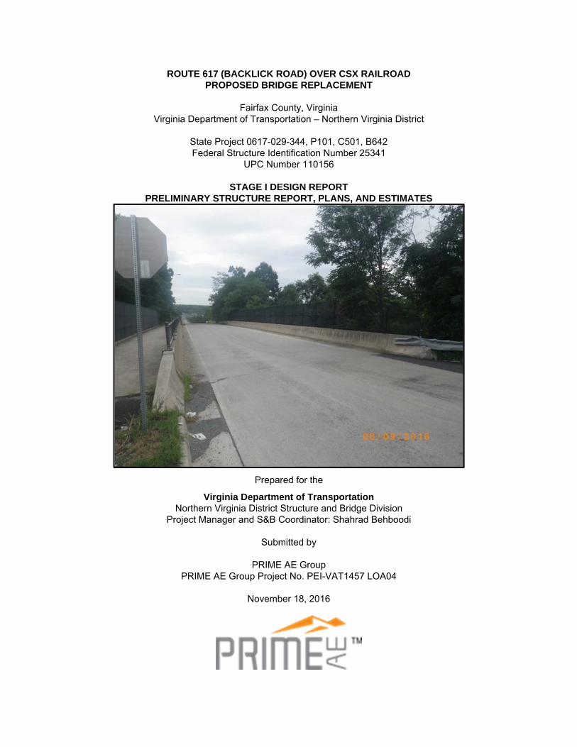
ROUTE 617 (BACKLICK ROAD) OVER CSX RAILROAD PROPOSED BRIDGE REPLACEMENT
Fairfax County, Virginia
Virginia Department of Transportation – Northern Virginia District
State Project 0617-029-344, P101, C501, B642 Federal Structure Identification Number 25341
UPC Number 110156
STAGE I DESIGN REPORT PRELIMINARY STRUCTURE REPORT, PLANS, AND ESTIMATES
Prepared for the
Virginia Department of Transportation Northern Virginia District Structure and Bridge Division
Project Manager and S&B Coordinator: Shahrad Behboodi
Submitted by
PRIME AE Group PRIME AE Group Project No. PEI-VAT1457 LOA04
November 18, 2016
Stage I Bridge Report Summary Form
Project Name: Replacement of Rte. 617 (Backlick Road) over CSX Railroad Date: 11/18/2016
Fed Structure ID (New) TBD UPC: 110156
Fed Structure ID (Exist) 25341
State Project Number: 0617-029-344, P101, C501, B642
County of: Fairfax District: Northern Virginia
Facility Carried: Rte. 617 Over CSX Railroad
This project is programmed for Federal Aid. Funding Source: State
Federal Project Number: TBD Federal Oversight: TBD
Prepared for the
Virginia Department of Transportation
Structure and Bridge Division Shahrad Behboodi, S&B Coordinator & Project Manager, (703)-259-2304
Submitted by
Steve Mackey, PRIME AE Group (703)-364-5562
Recommended Bridge Structural Summary:
Superstructure: Type: Multi-beam steel plate girder with composite concrete deck Units: One simple span unit Span Layout: 135’-0” Skew Angle: 22° Material – Steel (ASTM A709 Grade 50W) Superstructure width has been selected using: P=24 ft. Left Shoulder=2 ft. Right shoulder=2 ft. Median= ft. A Design Exception is not required There is 1 lane in each direction.. Through lane width is 12'. Total Pavement +Shoulder Width – 28'-0" face-to-face of curb and rail Parapet or Rail Type - BR 27 series, 42” high, Test Level TL-4 Bridge Deck Width (Bridge Surface Width): 45'-2" Out to Out of Deck width Pedestrian and Bicycle facilities do not meet shown in Volume 5 Part 2 Chapter 20 A Design Waiver is required Transverse Joint Type(s) - Structure will be Jointless Structure meets requirements for a jointless structure shown in Volume 5 Part 2 Chapter 17. A Design Waiver is not required Deck Width meets limitations in I&IM 80, a Longitudinal Joint is not required. A Design Waiver is not required
Substructure: Proposed Abutment A Type – Semi-Integral with MSE Wall Proposed Abutment B Type – Semi-Integral with MSE Wall Proposed Pier Type(s) – N/A Piers N/A be designed for collision. Pier protection N/A required. Proposed Foundation: Deep foundations (piles)
Clearances: Minimum Vertical Clearance: - 24’-3” Minimum Horizontal Clearance: - 25’-0”
Bridge crosses Railroad track(s). Geometry allows for 3 track(s)
Preliminary Hydraulic Analysis: Freeboard above design flood (25 Year) – N/A If 100 year storm floods bridge include: N/A Return Period of roadway flood event: N/A years
Scour at this location has not been computed. Scour is not expected to effect foundation design. A Design Waiver is not required
Recommended Bridge Cost Summary:
Estimated Costs*: The costs below represent Structure and Roadway/MOT. Estimated Cost of recommended layout - $7,625,300 bridge+related cost impacts. Ratio of recommended layout to lowest cost alternative considered: 1.00 Cost/SF this layout: $1,250 for bridge+related cost impacts. Estimate is not based on Trnsport. The detailed cost estimate is not included with the supplemental data.
This recommendation is the lowest cost structure solution. Justification for a cost differential is not presented in the narrative appendix. (*Estimated Cost does include Preliminary and Construction Engineering as well as 20% Contingency.)
Bridge Alternatives Developed:
Bridge Alternative forms are attached. Bridge Alternatives are presented in the Stage I Report.
Special construction Considerations:
Aesthetics - Aesthetic requirements are not anticipated Stage Construction - Stage Construction is not anticipated

Roadway Coordination Data Summary
Data not shown is provided on roadway plans provided as supplementary data Recommended structure will not be functionally obsolete. Based on Roadway Plans dated: On Bridge
Current ADT(year): 2200 (2015) Design ADT(year): (Not Available)
% Trucks: 25% Design Speed: 30 mph Posted Speed: (35) mph, See Stage I Report for more details
Reduced Design Speed (if applicable) N/A Is the road carried on the NHS? No
Functional Classification: Urban Local Street Min. Design Standard: GS-8 Existing Dimensions 2' - 24' - 2' Proposed Dimensions 2' - 24' - 2'
Max Grade -7.00 % Profile type Hump Vert Curve Under Bridge N/A (if applicable)
Current ADT(year): ( ) Design ADT(year): ( )
% Trucks: Design Speed: mph Posted Speed: mph
Reduced Design Speed (if applicable) Is the road under on the NHS?
Functional Classification: Min. Design Standard: Existing Dimensions Proposed Dimensions
Max Grade % Profile type The geometrics of the road approaching the structure include the position and alignment of the approach guardrail, if applicable. When bridge is an overpass then lateral clearances beneath the structure constitute part of the control geometrics and must be shown. If an existing structure at this site is to remain in place, its primary geometrics and its dimensional relationship to the proposed structure are included in the data.
Recommended Bridge Geometrics Summary: Geometrics: This project must meet
Low Volume Road Standards RRR Stds VDOT Road Design Manual and AASHTO Green Book AASHTO Green Book only (First Cities)
PM 100 attached Scoping Report Attached Current Road Plans Attached
Roadway width conforms to Volume 5 Part 2 Chapter 6 File No. 06-02-07 which controls the design. A Design Waiver is not required.
Roadway includes provisions for bicycles, Roadway is a shared roadway no modification to geometrics is required Roadway is a signed shared roadway Bicycle Lane is designated by striping, signing and pavement markings. Parapets and lane widths conform to the requirements of Volume 5 Part 2 Chapter 6. A Design Waiver is not required.
Pedestrian facilities are included: Sidewalk(s) does not meet requirements of Volume 5 Part 2 Chapter 6 are met; a 54” crash tested railing has been provided. A Design Waiver is required.
Bridge is on horizontal curve or within 200ft of PC/PT: Stopping sight distances meet requirements of Volume 5 Part 2 Chapter 6.
A Design Waiver is not required. See the preliminary structure report for additional information regarding the Design Waiver.
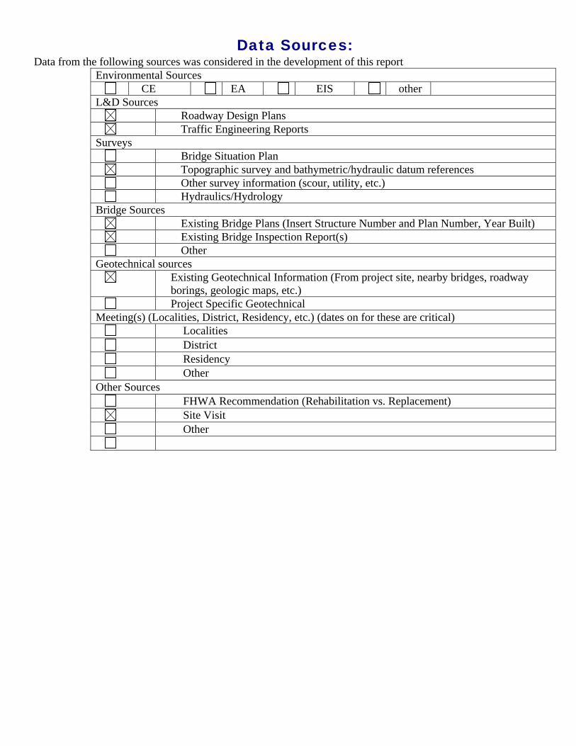
Data Sources: Data from the following sources was considered in the development of this report
Environmental Sources CE EA EIS other
L&D Sources Roadway Design Plans Traffic Engineering Reports
Surveys Bridge Situation Plan Topographic survey and bathymetric/hydraulic datum references Other survey information (scour, utility, etc.) Hydraulics/Hydrology
Bridge Sources Existing Bridge Plans (Insert Structure Number and Plan Number, Year Built) Existing Bridge Inspection Report(s) Other
Geotechnical sources Existing Geotechnical Information (From project site, nearby bridges, roadway
borings, geologic maps, etc.) Project Specific Geotechnical
Meeting(s) (Localities, District, Residency, etc.) (dates on for these are critical) Localities District Residency Other
Other Sources FHWA Recommendation (Rehabilitation vs. Replacement) Site Visit Other
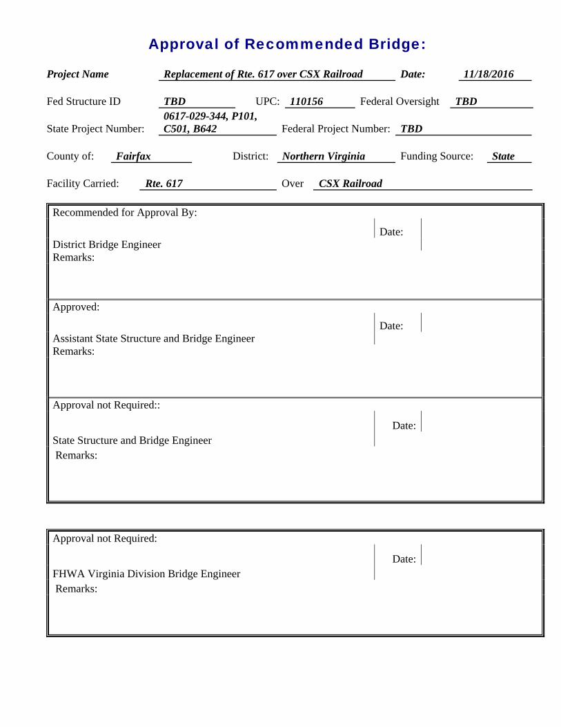
Approval of Recommended Bridge:
Project Name Replacement of Rte. 617 over CSX Railroad Date: 11/18/2016
Fed Structure ID TBD UPC: 110156 Federal Oversight TBD
State Project Number: 0617-029-344, P101, C501, B642 Federal Project Number: TBD
County of: Fairfax District: Northern Virginia Funding Source: State
Facility Carried: Rte. 617 Over CSX Railroad
Recommended for Approval By:
Date: District Bridge Engineer Remarks:
Approved:
Date: Assistant State Structure and Bridge Engineer Remarks:
Approval not Required::
Date: State Structure and Bridge Engineer Remarks:
Approval not Required:
Date: FHWA Virginia Division Bridge Engineer Remarks:
Stage I Report Route 617 (Backlick Road) over CSX Railroad ____________________________________________________________________________________________________________________________________________________________________________________________________________________________________________________________________________________________________________________________________________________________________________________________________________________________________
i
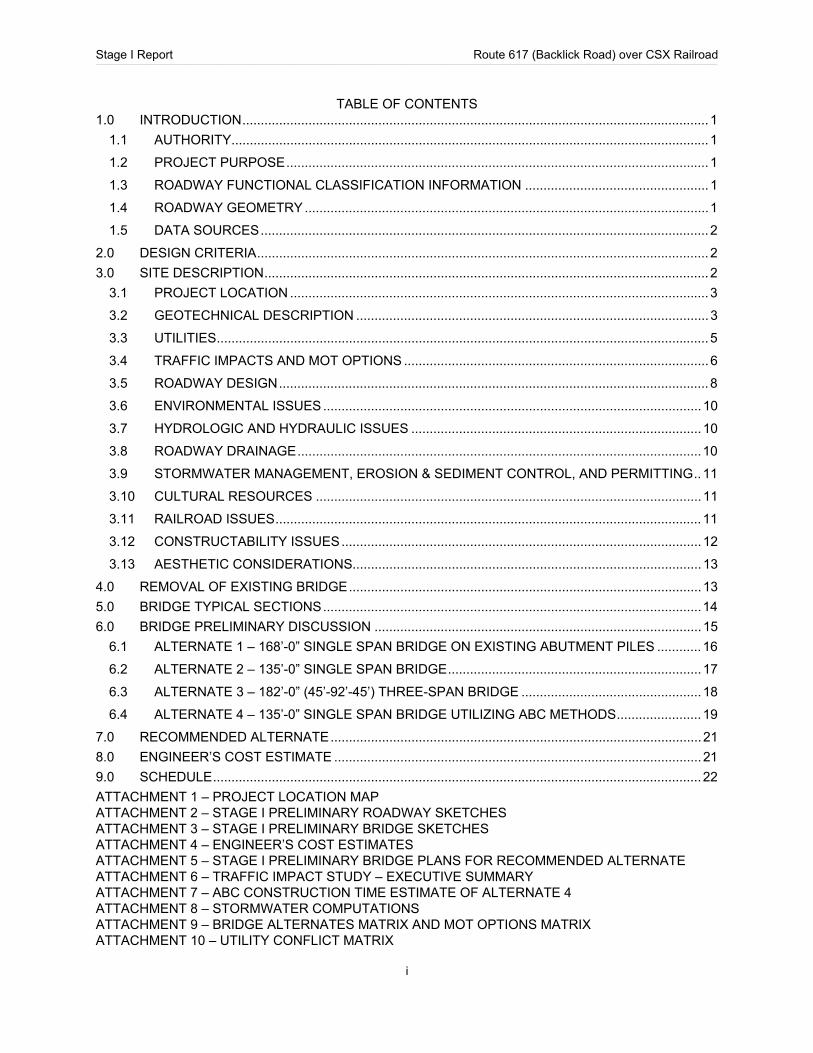
TABLE OF CONTENTS 1.0 INTRODUCTION ............................................................................................................................... 1
1.1 AUTHORITY .................................................................................................................................. 1
1.2 PROJECT PURPOSE ................................................................................................................... 1
1.3 ROADWAY FUNCTIONAL CLASSIFICATION INFORMATION .................................................. 1
1.4 ROADWAY GEOMETRY .............................................................................................................. 1
1.5 DATA SOURCES .......................................................................................................................... 2
2.0 DESIGN CRITERIA ........................................................................................................................... 2
3.0 SITE DESCRIPTION ......................................................................................................................... 2
3.1 PROJECT LOCATION .................................................................................................................. 3
3.2 GEOTECHNICAL DESCRIPTION ................................................................................................ 3
3.3 UTILITIES ...................................................................................................................................... 5
3.4 TRAFFIC IMPACTS AND MOT OPTIONS ................................................................................... 6
3.5 ROADWAY DESIGN ..................................................................................................................... 8
3.6 ENVIRONMENTAL ISSUES ....................................................................................................... 10
3.7 HYDROLOGIC AND HYDRAULIC ISSUES ............................................................................... 10
3.8 ROADWAY DRAINAGE .............................................................................................................. 10
3.9 STORMWATER MANAGEMENT, EROSION & SEDIMENT CONTROL, AND PERMITTING .. 11
3.10 CULTURAL RESOURCES ......................................................................................................... 11
3.11 RAILROAD ISSUES .................................................................................................................... 11
3.12 CONSTRUCTABILITY ISSUES .................................................................................................. 12
3.13 AESTHETIC CONSIDERATIONS ............................................................................................... 13
4.0 REMOVAL OF EXISTING BRIDGE ................................................................................................ 13
5.0 BRIDGE TYPICAL SECTIONS ....................................................................................................... 14
6.0 BRIDGE PRELIMINARY DISCUSSION ......................................................................................... 15
6.1 ALTERNATE 1 – 168’-0” SINGLE SPAN BRIDGE ON EXISTING ABUTMENT PILES ............ 16
6.2 ALTERNATE 2 – 135’-0” SINGLE SPAN BRIDGE ..................................................................... 17
6.3 ALTERNATE 3 – 182’-0” (45’-92’-45’) THREE-SPAN BRIDGE ................................................. 18
6.4 ALTERNATE 4 – 135’-0” SINGLE SPAN BRIDGE UTILIZING ABC METHODS ....................... 19
7.0 RECOMMENDED ALTERNATE ..................................................................................................... 21
8.0 ENGINEER’S COST ESTIMATE .................................................................................................... 21
9.0 SCHEDULE ..................................................................................................................................... 22
ATTACHMENT 1 – PROJECT LOCATION MAP ATTACHMENT 2 – STAGE I PRELIMINARY ROADWAY SKETCHES ATTACHMENT 3 – STAGE I PRELIMINARY BRIDGE SKETCHES ATTACHMENT 4 – ENGINEER’S COST ESTIMATES ATTACHMENT 5 – STAGE I PRELIMINARY BRIDGE PLANS FOR RECOMMENDED ALTERNATE ATTACHMENT 6 – TRAFFIC IMPACT STUDY – EXECUTIVE SUMMARY ATTACHMENT 7 – ABC CONSTRUCTION TIME ESTIMATE OF ALTERNATE 4 ATTACHMENT 8 – STORMWATER COMPUTATIONS ATTACHMENT 9 – BRIDGE ALTERNATES MATRIX AND MOT OPTIONS MATRIX ATTACHMENT 10 – UTILITY CONFLICT MATRIX

Stage I Report Route 617 (Backlick Road) over CSX Railroad ____________________________________________________________________________________________________________________________________________________________________________________________________________________________________________________________________________________________________________________________________________________________________________________________________________________________________
1
1.0 INTRODUCTION
1.1 AUTHORITY
This study was authorized by the Structure and Bridge Division of the Virginia Department of Transportation (VDOT) as part of the design services for the replacement of Route 617 (Backlick Road) Bridge over CSX Railroad, Fairfax County (State Project No. 0617-029-344, P101, C501, B642). The VDOT Project Manager and Structure & Bridge coordinator is Shahrad Behboodi, and he can be contacted at VDOT’s Northern Virginia District at (703) 259-2304 and [email protected]. PRIME AE Group is to provide the Stage I bridge design services per Letter of Agreement No. 4, dated August 15, 2016 with VDOT.
1.2 PROJECT PURPOSE
The purpose of this project is to replace the existing two-lane prestressed concrete girder bridge that carries Backlick Road over CSX railroad with a bridge that accommodates the addition of a third CSX railroad track. Additionally, the new bridge will correct the existing substandard vertical clearance above the active CSX railroad tracks and increase the vertical clearance to accommodate the potential future electrification for the CSX railroad as part of the Atlantic Gateway Project, which includes the DC to Richmond Southeast High Speed Rail project. The new structure will be designed and constructed to meet current applicable standards.
The scope of work for this project consists of a Stage I preliminary structure report, with supporting documentation and recommendations for review. Preliminary roadway plans have also been developed for Backlick Road. The results of the preliminary design are discussed herein.
1.3 ROADWAY FUNCTIONAL CLASSIFICATION INFORMATION
The VDOT functional classification of Route 617 over CSX Railroad is Urban Local Street. The current average annual daily traffic (AADT) is estimated to be 2200 vehicles per day (from VDOT, Traffic Engineering Division 2015) with approximately 25% truck traffic. According to the VDOT standards for Urban Local Street the required design speed is 30 mph. The current posted speed limit along northbound Backlick Road at Cinder Bed Road is 35 mph.
1.4 ROADWAY GEOMETRY
The alignment along Backlick Road is assumed to run north-south for layout and reference purposes. Roadway plans have been prepared for four bridge alternates with consideration of three maintenance of traffic options. The existing horizontal alignment consists of a tangent section within the project limits with the exception of a curve on the northern end of the project where Backlick Road terminates into a private commercial property. The existing vertical alignment is on a large vertical curve over the existing bridge. The horizontal alignment will be maintained in the proposed condition and the vertical alignment will be raised to accommodate the required vertical clearance over the proposed location of the CSX tracks. Two vertical alignments have been evaluated that work in partnership with the proposed bridge alternates. The proposed Stage I roadway sketches are provided in Attachment 2 of this report.
The existing posted speed limit on Backlick Road northbound at Cinder Bed Road is 35 mph. However, per VDOT standards and as-builts (Project 0617-029-328, C501, B619) sheet 24 of 34, the design speed for this section of the roadway is 30 mph. Therefore, a design speed of 30 mph was used for the geometric design of the roadway.
Preliminary Field Inspection (PFI) plans are being developed by PRIME AE Group and will be submitted to VDOT after the submission of the final Stage I Design report. The PFI plans provide specific information regarding the approach roadway geometry.
Stage I Report Route 617 (Backlick Road) over CSX Railroad ____________________________________________________________________________________________________________________________________________________________________________________________________________________________________________________________________________________________________________________________________________________________________________________________________________________________________
2
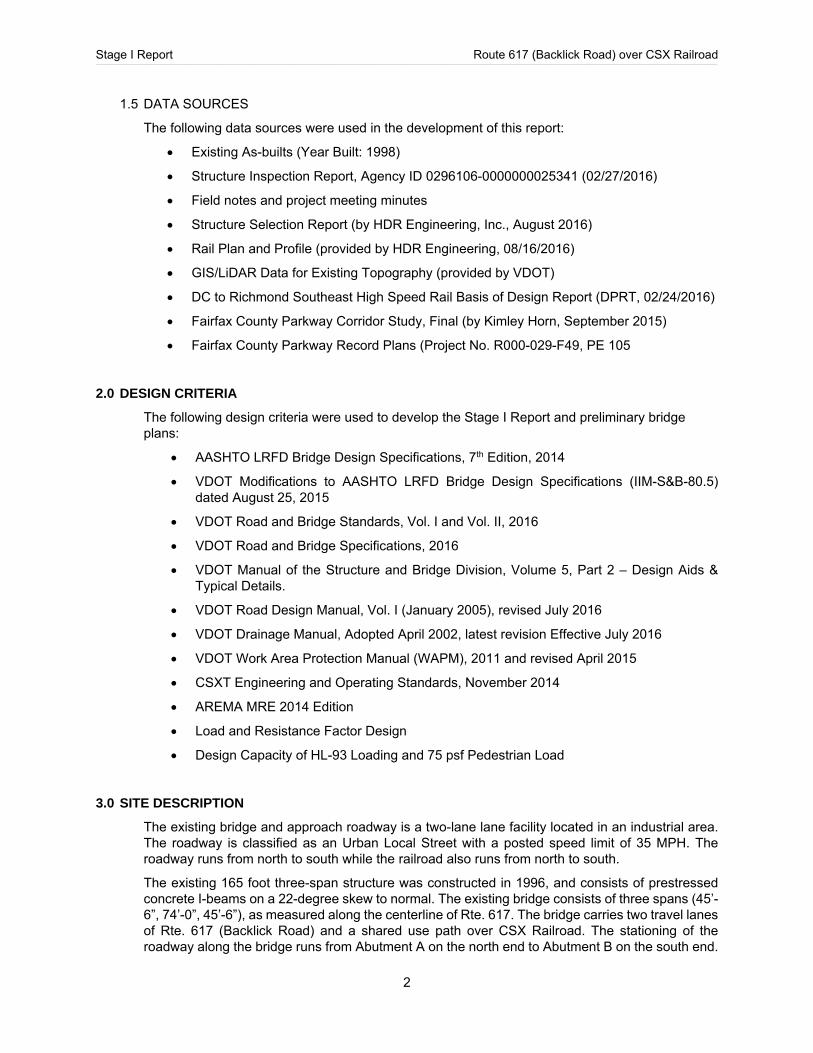
1.5 DATA SOURCES
The following data sources were used in the development of this report:
Existing As-builts (Year Built: 1998)
Structure Inspection Report, Agency ID 0296106-0000000025341 (02/27/2016)
Field notes and project meeting minutes
Structure Selection Report (by HDR Engineering, Inc., August 2016)
Rail Plan and Profile (provided by HDR Engineering, 08/16/2016)
GIS/LiDAR Data for Existing Topography (provided by VDOT)
DC to Richmond Southeast High Speed Rail Basis of Design Report (DPRT, 02/24/2016)
Fairfax County Parkway Corridor Study, Final (by Kimley Horn, September 2015)
Fairfax County Parkway Record Plans (Project No. R000-029-F49, PE 105
2.0 DESIGN CRITERIA
The following design criteria were used to develop the Stage I Report and preliminary bridge plans:
AASHTO LRFD Bridge Design Specifications, 7th Edition, 2014
VDOT Modifications to AASHTO LRFD Bridge Design Specifications (IIM-S&B-80.5) dated August 25, 2015
VDOT Road and Bridge Standards, Vol. I and Vol. II, 2016
VDOT Road and Bridge Specifications, 2016
VDOT Manual of the Structure and Bridge Division, Volume 5, Part 2 – Design Aids & Typical Details.
VDOT Road Design Manual, Vol. I (January 2005), revised July 2016
VDOT Drainage Manual, Adopted April 2002, latest revision Effective July 2016
VDOT Work Area Protection Manual (WAPM), 2011 and revised April 2015
CSXT Engineering and Operating Standards, November 2014
AREMA MRE 2014 Edition
Load and Resistance Factor Design
Design Capacity of HL-93 Loading and 75 psf Pedestrian Load
3.0 SITE DESCRIPTION
The existing bridge and approach roadway is a two-lane lane facility located in an industrial area. The roadway is classified as an Urban Local Street with a posted speed limit of 35 MPH. The roadway runs from north to south while the railroad also runs from north to south.
The existing 165 foot three-span structure was constructed in 1996, and consists of prestressed concrete I-beams on a 22-degree skew to normal. The existing bridge consists of three spans (45’-6”, 74’-0”, 45’-6”), as measured along the centerline of Rte. 617. The bridge carries two travel lanes of Rte. 617 (Backlick Road) and a shared use path over CSX Railroad. The stationing of the roadway along the bridge runs from Abutment A on the north end to Abutment B on the south end.
Stage I Report Route 617 (Backlick Road) over CSX Railroad ____________________________________________________________________________________________________________________________________________________________________________________________________________________________________________________________________________________________________________________________________________________________________________________________________________________________________
3
The travel width of the existing bridge is approximately 30’-0” measured face-to-face of curbs with an out-to-out width of approximately 44’-10”. The shared use path (SUP) is 10’-6” wide and separated from the northbound lane by a barrier. There is no sidewalk next to the southbound lane.
There are no utilities attached to the existing bridge structure, but there are overhead utility lines parallel to and approximately 25 feet west of the bridge. There is also an underground fiber optic cable running parallel to the railroad located to the east of existing Pier 2. The land in the immediate vicinity of the project is generally wooded, however there are some industrial and commercial businesses located nearby.
3.1 PROJECT LOCATION
The bridge is located on Route 617 over CSX Railroad approximately 300 feet east of the Route 286 (Fairfax County Parkway) and Route 617 (Backlick Road) intersection in Fairfax County. The bridge is approximately 0.8 mile from Interstate 95 to the north. The project location map is provided in Attachment 1 of this report. The proposed bridge will be constructed in the same location as the existing bridge.
3.2 GEOTECHNICAL DESCRIPTION
Based on the data available in the existing as-built plans, including the existing boring logs, it has been determined that the substructure units for the new bridge replacement structure will be founded on deep foundations (most likely piles).
Per the existing as-built plans, the bridge is supported on HP12x53 piles. The average pile lengths for Pier 1 and Pier 2 are 23.6 and 26 lineal feet, respectively. The average pile lengths for Abutment A and Abutment B are 41.9 and 39.7 lineal feet, respectively.
The as-built plans indicate eight (8) borings were completed for the current bridge with the boring depths ranging from 45 feet to 80 feet. The prepared logs indicate the subsurface profile generally contains interlayered silt, clay, and sand with all borings terminated on dense or very hard strata conditions. All borings were terminated without refusal and no rock coring was performed. Seasonal ground water conditions in the area of the pier foundations was measured within the upper 3 feet; in the area of the abutment foundations, ground water was measured at various depths ranging from approximately 15 feet to 44 feet.
Based on the pile lengths and the reported subsurface conditions, all piles for the current bridge structure were driven to practical refusal.
Minimum Preliminary Geotechnical Scope of Work for Backlick Road Bridge Replacement:
1. The number of borings for bridge structure foundations should adhere to Chapter III of the VDOT Manual of Instructions (MOI). Abutment borings shall extend to a minimum depth of 80 feet or auger refusal with continuous SPT sampling performed in the upper 10 feet and at 5-foot interval, thereafter. Abutment borings may be terminated at 80 feet if “N” values are greater than or equal to 50 for 3 consecutive 5-foot sampling intervals. If auger refusal occurs, borings shall be extended a minimum depth of 10 feet using rock coring methods. Percent recovery, RQD, RMR value, rock type, joint/fracture conditions, etc. should be included.
Soil borings and testing for retaining walls should also be in accordance with Chapter III of the VDOT Manual of Instructions (MOI). Borings should extend to a minimum depth of 25 feet or auger refusal with continuous SPT sampling performed in the upper 10 feet and at 5-foot interval, thereafter.
Groundwater measurements and/or boring cave-in depths should be taken at completion and following minimum 24-hour stabilization period.

Stage I Report Route 617 (Backlick Road) over CSX Railroad ____________________________________________________________________________________________________________________________________________________________________________________________________________________________________________________________________________________________________________________________________________________________________________________________________________________________________
4
Boring locations shall be surveyed and staked with lat/long coordinates and ground elevations.
2. Laboratory Analyses: Soil classifications (Atterberg Limits and Grain Size Analyses) performed for each soil
type encountered (minimum 10 analyses). Natural moisture analyses performed on all SPT samples. Standard Proctor(s) and soil classifications (Atterberg Limits and Grain Size Analyses)
analyses performed on representative samples that may be used for backfill of structures.
3. Notify Miss Utility or private locater to mark all underground utilities prior to subsurface investigation.
4. Minimum reporting requirements: A plan of boring locations. A log showing the strata encountered for each boring and N-values. Laboratory test data. Subsurface conditions – soil, rock, and groundwater. Preliminary foundation recommendations with respect to foundation type(s) and
bearing capacity, H-piles, drilled shafts, micro-piles, etc. MSE and/or retaining wall construction recommendations: bearing capacity, earth
pressures, backfill requirements, etc. Temporary shoring recommendations. Global slope stability analyses and slope construction recommendations. Groundwater control and dewatering recommendations. Estimated settlements for foundation structures. Estimated time-rate of settlement. Future construction considerations with respect to existing below grade foundations. Other relevant information specific to the site.
Recommended Preliminary Minimum Geotechnical Scope of Work for Backlick Road Roadway Improvements:
1. A minimum of 4 borings (1 in east bound and 1 in west bound lanes for each approach). Borings should extend to a minimum depth of 10 feet or auger refusal with continuous SPT sampling performed. Existing pavement sections (base stone and pavement thickness) should be verified.
Groundwater measurements and/or boring cave-in depths should be taken at completion and following minimum 24-hour stabilization period.
Boring locations shall be surveyed and staked with lat/long coordinates and ground elevations.
2. Laboratory Analyses: Natural moisture analyses performed on all SPT samples. Standard Proctor, soil classifications (Atterberg Limits and Grain Size Analyses), and
CBR analyses should be performed on representative samples that may be used for backfill of structures and bridge approach subgrades (minimum 2 samples).
3. Notify Miss Utility or private locater to mark all underground utilities prior to subsurface investigation.
4. Minimum reporting requirements: A plan of boring locations. A log showing the strata encountered for each boring and N-values. Laboratory test data.
Stage I Report Route 617 (Backlick Road) over CSX Railroad ____________________________________________________________________________________________________________________________________________________________________________________________________________________________________________________________________________________________________________________________________________________________________________________________________________________________________
5
Subsurface conditions – soil, rock, and groundwater. Earthwork recommendations and fill placement requirements. New pavement design recommendations. Other relevant information specific to the site.
Final Geotechnical Scope of Work for Backlick Road Bridge Replacement:
Update and submit final report following review and comments pertaining to preliminary geotechnical report. Report to include:
Additional soil boring/testing results, if required. Final foundation recommendations. Procedures and monitoring criteria for installation of selected deep foundation system. Final revisions as necessary to address review comments.
All investigative procedures, laboratory analyses, and reporting requirements for subsurface investigations should adhere to applicable sections as outlined in Chapter III of the VDOT Manual of Instructions (July 2016). Any access to the CSXT right-of-way for soil borings, survey, or other data collection shall be coordinated directly with CSXT via the CSX website.
3.3 UTILITIES
The existing utilities shown on the plans were captured from the SU files provided by VDOT, field investigations, and the 1995 Fairfax County Parkway plans. The existing bridge does not carry or support any utilities, and there are unknown overhead utility lines parallel to and approximately 25 feet west of the bridge. Based on the field investigations, these lines are likely telephone and or cable TV. These lines run parallel to Backlick Road and are underground but then turn-up utility poles at the end of the bridge before crossing over the CSX Railroad. Based on the alternatives reviewed in this study, the overhead lines will likely require relocation to facilitate bridge construction but we will revisit in more detail when the utility designation is completed and an Alternate is selected.
There is also an underground fiber optic cable that runs parallel to the railroad tracks and is located approximately 10 feet south of existing Pier 2. The exact location of this utility is currently unknown, but a Utility Survey, including test pits, has been ordered. It is anticipated that relocation of this utility will be very costly and require a significant splice. It is known that the three span alternate will require this utility line to be relocated due to the proposed placement of the piers. The single span alternates can likely be constructed without impacting the line. The future grading of the embankment slope, which will occur when the existing tracks are shifted and the third railroad track is constructed, will possibly expose the fiber optic line and require it to be re-buried or relocated. There is a possibility that there are one or two additional underground utilities located adjacent to the railroad tracks. The existence and location of these other utilities will be determined with the Utility Survey. Only the utilities that interfere with construction of the bridge will be relocated to accommodate the bridge. Utility relocation will not be done for utilities that will be impacted by the track improvements.
After the utilities are designated and shown on the plans, a Utility Field Investigation (UFI) will be held to start relocation work if utility relocation is needed. Any pipeline/wireline facilities to be installed, modified, removed, or retired in place within the CSXT right-of-way must be coordinated directly with CSXT Property Services.
In addition, the roadway approach construction creates conflicts with existing lighting, signal hand boxes, traffic signal controller cabinets, and underground telephone. To assist VDOT review of the utilities, we have included a Utility Conflict Matrix (see Attachment 10) that indicates anticipated utility conflicts along the project limits. This will be updated upon receiving the Utility Designation File and used to establish future utility test pit locations.
Stage I Report Route 617 (Backlick Road) over CSX Railroad ____________________________________________________________________________________________________________________________________________________________________________________________________________________________________________________________________________________________________________________________________________________________________________________________________________________________________
6
3.4 TRAFFIC IMPACTS AND MOT OPTIONS
Backlick Road at the crossing of the CSX railroad is a lightly travelled roadway with an Average Daily Traffic (ADT) of 2,200 vehicles per day (vpd). The peak hour volumes measured in September 2016 are generally less than 200 vehicles per hour (vph) for the peak direction.
The area that is served by Backlick Road is an industrial and commercial area with high truck volumes. Other than Backlick Road, access to the area is limited to Newington Road. Newington Road connects on the west through a one lane CSX underpass, and to the east through a residential neighborhood.
A traffic study was conducted, and submitted to the Department on October 6, 2016, to determine the congestion impacts of a full closure of Backlick Road at the CSX Railroad crossing versus the impacts with a multi-staged construction approach. The executive summary of the traffic study is included for reference in Attachment 6 of this report. The study concluded:
“Backlick Road at the bridge over CSX railroad is a lightly used local roadway. In addition, a large portion of the traffic on Backlick Road and Newington Road is external “cut through” traffic; some of this traffic will divert to other roadways during bridge construction.
Staged construction will allow traffic to continue over the CSX Railroad during construction. Two alternatives are possible with only minor impacts to traffic flow. However, staged construction will either necessitate one way operations or removing pedestrian access. Two way operations with pedestrian access is not feasible.
A full closure of the bridge is not expected to create significant congestion along the proposed detour route. Furthermore, conditions on Fairfax County Parkway and other primary routes are not expected to be significantly affected.”
At this time no decision has been made as to whether a full closure with detour or staged construction will be implemented. The Traffic Study analyzes the congestion impact of the full detour and staged construction options and is provided separately. This document shows plans for each of the options and summarizes the advantages and disadvantages of each.
There are three general Maintenance of Traffic (MOT) options; full closure with detour, staged construction with one lane and pedestrian access, and staged construction with two lanes open. The MOT option utilizing staged construction with one lane and pedestrian access was evaluated for two variants. Both variants of this option are discussed within this section of the report. The remainder of the report will refer to the three general MOT options. The following MOT options have been evaluated:
MOT Option A: Full Closure and Detour.
MOT Option B1: One Lane – Alternating Two-Way Traffic, with Pedestrian Access.
MOT Option B2: One Lane – Two-Way Traffic by time of day, with Pedestrian Access.
MOT Option C: Two Lanes, without Pedestrian Access.
MOT Option A: Full Closure and Detour.
To implement this option, a more extensive community outreach program will be necessary to inform Newington area businesses and the Newington residential area. A limited community has been conducted to date. Access to the spur from Backlick Road to Fairfax County will also be closed.
The detour from Fairfax County Parkway will be to Loisdale Road to Newington Road to Cinder Bed Road. This detour directs traffic through the CSX underpass on Newington Road.
The existing bike and pedestrian trail will not be maintained. The trail is lightly used and there are no residential bike and pedestrian generators located nearby. Bus service does not use
Stage I Report Route 617 (Backlick Road) over CSX Railroad ____________________________________________________________________________________________________________________________________________________________________________________________________________________________________________________________________________________________________________________________________________________________________________________________________________________________________
7
Backlick Road. This portion of the trail is part of a larger County network and it is possible that bike or hike hobbyists rely on the crossing.
To maintain pedestrian access over CSX Railroad three alternatives are available: Construct a temporary pedestrian bridge to the south (between Backlick and Fairfax
County Parkway); Provide a protected area in the shoulder of the Fairfax County Parkway for bike and
pedestrian use. Shuttle bike and pedestrian users around the construction.
Advantages of Option A: Reduced project duration and construction cost. Reduce risk and improved safety to construction workers and motorists. Reduced environmental impacts from less complicated construction and fewer
vehicles in construction area. Reduced construction cost due to reduced bridge width. Bridge width will be 45’ (+/-).
Disadvantages of Option A: Detour will have modest effect on area congestion (see Traffic Study). Lack of egress from Newington area. Egress will be limited to the CSX underpass or
the Newington residential area. No bike or pedestrian access.
MOT Option B1: One Lane – Alternating Two Way Traffic, with Pedestrian Access.
Each of the staged construction alternates consist of several bridge and roadway pavement phases. Preliminary plans of these phases are in Attachment 2.
Phase I will consist of demolition of a portion of the existing bridge and construction of a 27 foot (+/-) section of new bridge in the space of the demolition. In Phase II traffic will shift to the new 27-foot section of bridge and the remainder of the existing bridge will be demolished. Following demolition construction of the remainder of the new bridge will commence.
This staged option will require a temporary signal at each end of the bridge. Traffic will alternate between northbound and southbound. The type of actuation has not been determined. During low volume periods predetermined time splits will most likely be used.
Bike and pedestrian access will be maintained via a 5-foot sidewalk through the work zone.
Advantages of Option B1: Maintains bike and pedestrian access. No detour of traffic.
Disadvantages of Option B1: Increased risk to workers and motorists than detour. Longer project duration and greater construction cost than detour. Temporary traffic signal needed. Traffic heading southbound is expected to create queues that may block through traffic
on Fairfax County Parkway. Wider bridge width. The final bridge width will be 57 feet (+/-).
MOT Option B2: One Lane – Two Way Traffic by time of day, with Pedestrian Access.
This option is identical to MOT Option B1 with regards to the construction process; however, this option will not use a temporary signal. Traffic will travel southbound between 5am and 2pm and northbound during the remainder of the day.
Detours will be necessary for the direction of traffic not served. The detour will be the same as the detour for MOT Option A. Pedestrian access will be via a 5-foot sidewalk.
Stage I Report Route 617 (Backlick Road) over CSX Railroad ____________________________________________________________________________________________________________________________________________________________________________________________________________________________________________________________________________________________________________________________________________________________________________________________________________________________________
8
Advantages of Option B2: Maintains bike and pedestrian access. Traffic heading SB not expected to queue or block Fairfax County Parkway traffic. No need for temporary traffic signal.
Disadvantages of Option B2: Detour by time of day necessary. Potentially confusing signing and marketing
necessary. Increased risk to workers and motorists than detour. Longer project duration and greater construction cost than detour. Wider bridge width. The final bridge width will be 57 feet (+/-)
MOT Option C: Two Lanes, without Pedestrian Access.
The construction process for this option is identical to the other staged alternates. However, traffic control is much simpler in that there is no need for a regular detour or a temporary signal.
This option uses the same general width of roadway for Phase II. As such there is not enough width for a bike pedestrian lane during Phase II. To maintain bike and pedestrian access, the same alternatives as shown in MOT Option A will be used.
Advantages of Option C: Best vehicular capacity over bridge; most similar to current conditions. Signing and marking less complicated.
Disadvantages of Option C: Increased risk to workers and motorists than detour. Longer project duration and greater construction cost than detour. No access for bike or pedestrians. Widest bridge width. Final bridge width will be 61 feet (+/-).
It is likely that there will be the need for a short term full closure of the roadway and bridge even with staged construction (MOT Options B and C). With Alternative 2 the profile is approximately 6 feet (+/-) above the current roadway. During phase 3 of the construction, 27 feet (+/-) of new bridge and adjacent roadway will be constructed. Both will be on the higher profile than the existing bridge and roadway.
Before traffic can be placed on the new bridge and roadway, a portion of the existing connector road will also need to be raised to prevent a drop off in grade. During this sub-phase, traffic will not be able to travel on the new bridge or the existing bridge.
The time to build up the roadway to eliminate the drop off will depend if this construction is temporary or permanent. It is expected that the full closure with staged construction will be more than 3 weeks.
3.5 ROADWAY DESIGN
A 30 mph design speed has been used for the geometric design of the roadway. However, since the posted speed limit of 35 mph is greater than the design speed due to the current roadway classification, a speed limit study should be considered.
Roadway Typical Section:
The roadway typical section consists of a normal crown with two 12’-0” lanes, 4’-0” paved and 4’-0” grass shoulders on the southbound roadway, and a 2’-0” combination curb and gutter on the northbound roadway. In addition, the existing 8’-0” wide shared use path (SUP) will be reconstructed with 3’-0” grass buffer behind the curb on the northbound roadway. The shared use path width will transition from 8’-0” along the roadway to 15’-6” on the bridge approaches.
Stage I Report Route 617 (Backlick Road) over CSX Railroad ____________________________________________________________________________________________________________________________________________________________________________________________________________________________________________________________________________________________________________________________________________________________________________________________________________________________________
9
The basic roadway typical section is 30’-0” wide between the face of curb and edge of the paved shoulder. The bridge typical section is discussed in more detail in Section 5.0.
To validate the proposed typical section and roadway geometry, WB-67 truck turning simulations were performed using the Auto-Turn software. The turning movement wheel path for the worst case scenario is shown on the roadway plans (see Attachment 2). Large trucks traveling southbound are unable to clear their rear wheels without encroaching on the northbound lanes. The situation exists for all of the bridge alternates and is marginally improved for Alternate 2. Features to provide more room for southbound trucks will be added in final design. A wedge at the northwest corner of the bridge may be necessary.
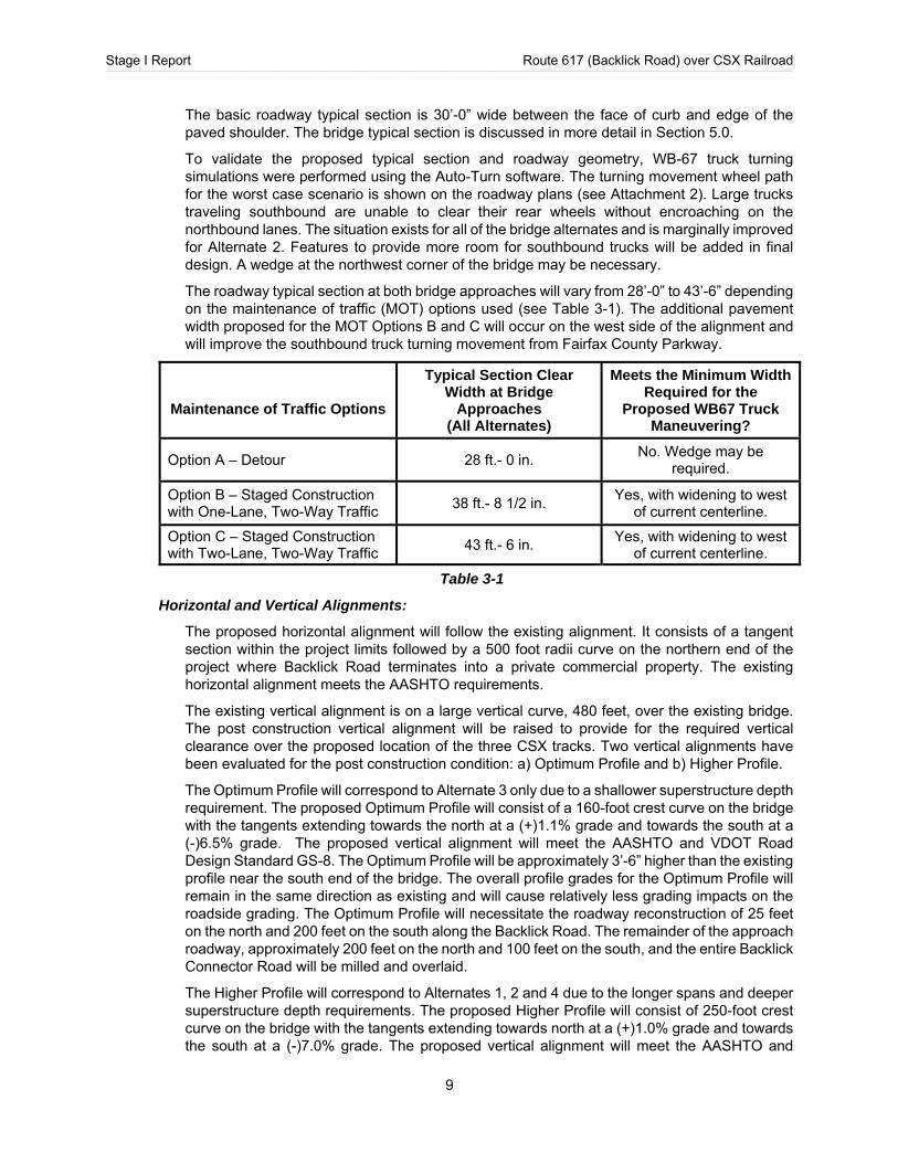
The roadway typical section at both bridge approaches will vary from 28’-0” to 43’-6” depending on the maintenance of traffic (MOT) options used (see Table 3-1). The additional pavement width proposed for the MOT Options B and C will occur on the west side of the alignment and will improve the southbound truck turning movement from Fairfax County Parkway.
Maintenance of Traffic Options
Typical Section Clear Width at Bridge
Approaches (All Alternates)
Meets the Minimum Width Required for the
Proposed WB67 Truck Maneuvering?
Option A – Detour 28 ft.- 0 in. No. Wedge may be
required.
Option B – Staged Construction with One-Lane, Two-Way Traffic
38 ft.- 8 1/2 in. Yes, with widening to west
of current centerline.
Option C – Staged Construction with Two-Lane, Two-Way Traffic
43 ft.- 6 in. Yes, with widening to west
of current centerline.
Table 3-1
Horizontal and Vertical Alignments:
The proposed horizontal alignment will follow the existing alignment. It consists of a tangent section within the project limits followed by a 500 foot radii curve on the northern end of the project where Backlick Road terminates into a private commercial property. The existing horizontal alignment meets the AASHTO requirements.
The existing vertical alignment is on a large vertical curve, 480 feet, over the existing bridge. The post construction vertical alignment will be raised to provide for the required vertical clearance over the proposed location of the three CSX tracks. Two vertical alignments have been evaluated for the post construction condition: a) Optimum Profile and b) Higher Profile.
The Optimum Profile will correspond to Alternate 3 only due to a shallower superstructure depth requirement. The proposed Optimum Profile will consist of a 160-foot crest curve on the bridge with the tangents extending towards the north at a (+)1.1% grade and towards the south at a (-)6.5% grade. The proposed vertical alignment will meet the AASHTO and VDOT Road Design Standard GS-8. The Optimum Profile will be approximately 3’-6” higher than the existing profile near the south end of the bridge. The overall profile grades for the Optimum Profile will remain in the same direction as existing and will cause relatively less grading impacts on the roadside grading. The Optimum Profile will necessitate the roadway reconstruction of 25 feet on the north and 200 feet on the south along the Backlick Road. The remainder of the approach roadway, approximately 200 feet on the north and 100 feet on the south, and the entire Backlick Connector Road will be milled and overlaid.
The Higher Profile will correspond to Alternates 1, 2 and 4 due to the longer spans and deeper superstructure depth requirements. The proposed Higher Profile will consist of 250-foot crest curve on the bridge with the tangents extending towards north at a (+)1.0% grade and towards the south at a (-)7.0% grade. The proposed vertical alignment will meet the AASHTO and
Stage I Report Route 617 (Backlick Road) over CSX Railroad ____________________________________________________________________________________________________________________________________________________________________________________________________________________________________________________________________________________________________________________________________________________________________________________________________________________________________
10
VDOT Road Design Standard GS-8. The Higher Profile will be approximately 6’-0” higher than the existing profile near the north end of the bridge. Due to the substantial rise in elevation, the Higher Profile requires significant amount of roadway reconstruction and causes larger impacts on the roadside grading. Accordingly, the roadway reconstruction of 250 feet on north and 250 feet on south along Backlick Road will be required. The remainder of Backlick Road, approximately 50 feet on north and 100 feet on south will be milled and overlaid. The Backlick Connector Road profile will be raised as high as four feet adjacent to Backlick Road and therefore, it will be necessary to reconstruct the roadway between Fairfax County Parkway and Backlick Road.
Attachment 2 contains roadway plans for each of the Alternates. Two additional plans have been prepared for Alternate 3 to show the wider bridge required for MOT B and C. Attachment 2 also contains plans describing the MOT options.
3.6 ENVIRONMENTAL ISSUES
A typical structure replacement project is usually addressed with a Programmatic Categorical Exclusion (Cat 15) NEPA document. It is anticipated that this project will likely qualify for a PCE. The State Environmental Review Process (SERP) is not required since this is a federally eligible project.
Screening for potential asbestos-containing materials is strongly recommended prior to dismantling the existing bridge.
3.7 HYDROLOGIC AND HYDRAULIC ISSUES
There are no hydrologic or hydraulic issues for this bridge located over CSX Railroad.
3.8 ROADWAY DRAINAGE
Roadway grading has been evaluated for two different profiles: a) Optimum Profile and b) Higher Profile. Plans showing the proposed profiles are in Attachment 2.
The Optimum Profile will correspond to proposed bridge Alternate 3 only due to a shallower superstructure depth requirement. The optimum profile will cause minimal grading impacts north of the proposed bridge however; it will necessitate roadway reconstruction of approximately 200 feet on the south end of the bridge. The road side grading will require fill along both sides of the roadway and cut into the existing embankment east of Backlick Road at the south end of the project. The overall grading and drainage pattern will remain the same as existing with exception of reconstruction of the curb inlet located just north of the proposed bridge. A roadside drainage ditch will be re-graded along the southbound side of Backlick Road south of the proposed bridge and will tie back to existing at the south end of the project. Remainder of the project grading will tie to existing with either cut or fill slopes and will outfall to existing outfalls.
The Higher Profile will correspond to proposed bridge Alternate 1, 2, and 4, which have deeper superstructure depth requirements. The Higher Profile requires significant grading and fill for approximately 250 feet on both north and south sides of the proposed bridge. The road side grading will require mostly fill along both sides of the roadway and cut into the existing embankment east of Backlick Road at the south end of the project. Also, due to the raised roadway profile, a highpoint is created near the north end of the bridge and therefore, there will be a slight change in drainage areas within the project limits. Accordingly, a new storm drain system will be required along Backlick Road on the north side of the proposed bridge. A roadside drainage ditch will be re-graded along southbound Backlick Road on the south side of the proposed bridge and will tie back to existing at the south end of the project. Remainder of the project grading will tie to existing with either cut or fill slopes and will outfall to existing outfalls.
Stage I Report Route 617 (Backlick Road) over CSX Railroad ____________________________________________________________________________________________________________________________________________________________________________________________________________________________________________________________________________________________________________________________________________________________________________________________________________________________________
11
3.9 STORMWATER MANAGEMENT, EROSION & SEDIMENT CONTROL, AND PERMITTING
Stormwater Management has been evaluated according to the VDOT Drainage Manual and Instruction and Information Memorandums IIM-LD-195.9, IIM-LD-242.5 and IIM-LD-251.3. Since the project disturbs more than 2,500 SF of land, stormwater management and erosion and sediment control permit will be required according to the Virginia Stormwater Management Handbook (2011) and July 1, 2014 Stormwater Regulations.
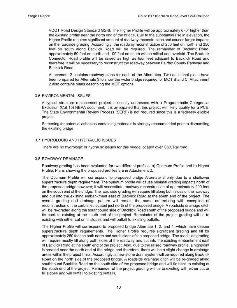
Accordingly, the post construction stormwater quality will be addressed by the purchase of nutrient credits. Preliminary runoff reduction analysis has been performed and summarized in Table 3-2. Refer to Attachment 8 for a detailed analysis. The post construction stormwater quantity requires 10-yr peak discharges to pre-existing conditions or lower. The increased runoff in post construction condition will be attenuated by the installation of check dams in roadside ditches along southbound Backlick Road on the south side of the bridge and a stormwater control structure in the existing low laying area located north of the Connector Road between Fairfax County Parkway and Backlick Road.
This project disturbs more than one acre of land therefore, Virginia Pollutant Discharge Elimination System (VPDES) will be required.
Design Alternate
MOT Option Total Land Disturbance
(LOD)
Qualified for Nutrient Credits?
(< 5 Acres LOD)
Nutrient Credits Required
(Phosphorous Reduction (Lb./Year)
1 A 1.90 Yes 0.49
2
A 1.96 Yes 0.50
B 2.07 Yes 0.60
C 2.08 Yes 0.65
3
A 1.74 Yes 0.48
B 1.72 Yes 0.60
C 1.73 Yes 0.65
4 A 1.96 Yes 0.50
Table 3-2
3.10 CULTURAL RESOURCES
There are no known cultural resource sites within the project limits. This bridge does not meet the age criteria to qualify as a historic property. Modern buildings and associated infrastructure dominate the immediate landscape.
3.11 RAILROAD ISSUES
The proposed bridge will be designed to accommodate the installation of a new third mainline track and a minor shift in the location of the two existing mainline tracks. The centerline to centerline of the existing tracks through the project vicinity will be approximately 14’-0”, and the centerline of the new track will be located 15’-0” to the east of the existing northbound mainline track. The addition
Stage I Report Route 617 (Backlick Road) over CSX Railroad ____________________________________________________________________________________________________________________________________________________________________________________________________________________________________________________________________________________________________________________________________________________________________________________________________________________________________
12
of this third track will result in a substandard horizontal clearance (less than 10 feet) at Pier 2 of the existing bridge, and therefore the pier must be removed to rectify the clearance issue. The standard horizontal clearance for CSXT is typically 25’-0” or greater; however, horizontal clearances of less than 25’-0” but greater than 18’-0” with a crash wall are acceptable pending CSXT approval. For this project the standard 25’-0” minimum horizontal clearance will be provided.
Furthermore, the current vertical clearance of the existing bridge over the railroad tracks is substandard at 22’-8”. The standard vertical clearance that needs to be provided, measured from top of high rail to lowest point of structure in the horizontal clearance area which extends 9’-0” to either side of the track centerline, is 23’-0”. However, as part of the requirements for the DC to Richmond Southeast High Speed Rail, the minimum vertical clearance that needs to be provided is 24’-3”. This 1’-3” increase from the CSXT standard will provide the necessary clearance to allow for the potential future electrification of the tracks.
The location of this bridge is over one of the busiest corridors of CSX Railroad that services numerous CSXT freight trains and Amtrak passenger trains. There are an estimated 78 trains per day so the available times for overhead demolition and construction will be highly dependent on the train schedule. CSXT is contractually obligated to maintain the Amtrak schedule. In order to maintain this schedule, construction will need to be coordinated accordingly and with consideration to the varying frequency of the CSXT freight trains.
3.12 CONSTRUCTABILITY ISSUES
The estimated time for construction of the proposed bridge will depend on the preferred method of construction. Currently there are three methods of construction under consideration: normal routine construction, staged construction, and accelerated bridge construction (ABC). The proposed bridge will be constructed in the same location as the existing bridge, though the footprint of the bridge may be slightly wider and/or longer as required for each alternate.
A construction duration of 7-11 months is estimated if normal routine construction methods are used. The duration of construction will be shortest for the single span alternates and will be longer for the three span alternate due to the need to fully demolish the existing piers as well as construct the new piers.
A construction duration of 13-16 months is estimated if staged construction methods are used. Similar to normal routine construction, the duration will be shortest for the single span alternates and longest for the three span alternate.
Finally, it is estimated that accelerated bridge construction methods can reduce the duration of construction of the single span alternate by approximately 1 month assuming a full bridge closure. Accelerated bridge construction methods were not evaluated for the stage construction options as directed by the Department.
Regardless of the method of construction, the erection of the new bridge will be greatly impacted by the volume of freight trains and passenger trains operating daily the tracks. Additionally, the availability of CSXT flaggers is very limited in this corridor. A flagger must be on site during construction, particularly for work over the track, so it will be important to coordinate the construction schedule with CSXT to minimize the need for flaggers and optimize the available work window around the train schedule. A CSXT flagger may be required for any work which requires entry onto the CSX track, and all work to be performed within 50 feet of the centerline of the track. The contractor must plan and perform the work in a manner such that the CSX tracks remain fully capable of carrying rail traffic throughout the work period and rail traffic is not delayed or otherwise impacted due to the work being performed.
Access to both sides of the proposed bridge will be achieved from the existing roadway approaches and right-of-way. Temporary construction clearances will not be allowed. The contractor shall not
Stage I Report Route 617 (Backlick Road) over CSX Railroad ____________________________________________________________________________________________________________________________________________________________________________________________________________________________________________________________________________________________________________________________________________________________________________________________________________________________________
13
be permitted to use the CSXT right-of-way for storage of materials or equipment during construction. The CSXT right-of-way must remain clear at all times.
At a minimum, there will be approximately 2’-0” between Stage I construction and Stage 2 demolition for the staged construction alternates. This should provide adequate space for temporary shoring, forming of the new abutments and piers (if utilized), and erection of the new superstructure.
There are overhead utility lines and at least one underground fiber optic cable in the area that may need to be relocated. The drainage ditches adjacent to the CSX tracks are to be restored to the original condition after construction.
3.13 AESTHETIC CONSIDERATIONS
There are no specific aesthetic requirements for the proposed bridge.
4.0 REMOVAL OF EXISTING BRIDGE
The removal of the existing Route 617 bridge will be completed in either one operation or in multiple phases of demolition depending on the MOT option selected for construction. The demolition will be in accordance with VDOT Specifications and CSXT Standards.
Regardless of the method of construction, the railroad tracks will need to be protected at all times from falling debris during the removal of the overhead bridge and from any debris rolling down the side slopes or otherwise coming into the area around the tracks which could affect train operations. According the CSXT Criteria for Overhead Bridges, a protection shield erected from the underside of the bridge over the track area must be provided to catch falling debris. The protection shield should be supported from the girders and will be designed for a minimum of 50 pounds per square foot plus the weight of the equipment, debris, personnel, and other loads to be carried. The construction and application of the protection shield will need to be evaluated to ensure it will have no impacts on the already substandard vertical clearance of the existing bridge.
The deck will be removed by cutting it in sections and lifting each section out. Large pieces of the deck are not to be allowed to fall on the protection shield. Additionally, a ballast protection system consisting of geofabric or canvas may need to be placed over the track to keep the ballast clean. The system will extend along the track structure for a minimum of 25’-0” beyond the limits of the demolition work. For the alternates that do not require the pier footing to be removed, the pier columns will be removed to the maximum extent possible, but not less than three feet below the final finished grade or two feet below the base of rail, whichever is lower. The other alternates will require the entire pier footing to be removed. Sheeting may be required for pier removal, but it is not anticipated that the necessary excavation will encroach on the CSXT Theoretical Live Load Zone of Influence for the recommended alternate. This will need to be re-evaluated if a different alternate is preferred by the Department.
All existing abutment and pier piles are to remain in place if it is anticipated that they will not obstruct construction of the new foundations. Where possible, the existing piles are to be re-used for the foundations of the new substructure units. The piles that are to be re-used may require testing to assess their condition. The location of the piles that are to be re-used is discussed for each alternate in further detail within the Bridge Preliminary Discussion (Section 6.0) subsections.
The removal schedule will need to be coordinated with CSXT as the times available for overhead demolition are highly dependent on the train schedule. All of the removal work within the track area will need to be performed during the available time windows when the trains are not passing the site. This was previously discussed in Sections 3.9 and 3.10 of this report.
Stage I Report Route 617 (Backlick Road) over CSX Railroad ____________________________________________________________________________________________________________________________________________________________________________________________________________________________________________________________________________________________________________________________________________________________________________________________________________________________________
14
5.0 BRIDGE TYPICAL SECTIONS
The proposed bridge typical sections are established based on existing roadway and traffic conditions, the VDOT Roadway Design Manual, and VDOT S&B Division Manual – Volume V, Part 2. The typical sections were discussed and decided in a meeting held with representatives from NOVA District Structure and Bridge, Location and Design, and Traffic Engineering on September 29, 2016.
Construction phasing will affect the overall width of the bridge. If traffic is maintained over the bridge throughout the construction project the southbound shoulder width will be wider than 2’. This is due to the need to increase the bridge width through the various stages of construction and demolition.
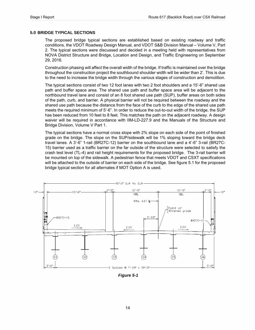
The typical sections consist of two 12 foot lanes with two 2 foot shoulders and a 15’-6” shared use path and buffer space area. The shared use path and buffer space area will be adjacent to the northbound travel lane and consist of an 8 foot shared use path (SUP), buffer areas on both sides of the path, curb, and barrier. A physical barrier will not be required between the roadway and the shared use path because the distance from the face of the curb to the edge of the shared use path meets the required minimum of 5’-6”. In order to reduce the out-to-out width of the bridge, the SUP has been reduced from 10 feet to 8 feet. This matches the path on the adjacent roadway. A design waiver will be required in accordance with IIM-LD-227.9 and the Manuals of the Structure and Bridge Division, Volume V Part 1.
The typical sections have a normal cross slope with 2% slope on each side of the point of finished grade on the bridge. The slope on the SUP/sidewalk will be 1% sloping toward the bridge deck travel lanes. A 3’-6” 1-rail (BR27C-12) barrier on the southbound lane and a 4’-6” 3-rail (BR27C-15) barrier used as a traffic barrier on the far outside of the structure were selected to satisfy the crash test level (TL-4) and rail height requirements for the proposed bridge. The 3-rail barrier will be mounted on top of the sidewalk. A pedestrian fence that meets VDOT and CSXT specifications will be attached to the outside of barrier on each side of the bridge. See figure 5.1 for the proposed bridge typical section for all alternates if MOT Option A is used.
Figure 5-1
Stage I Report Route 617 (Backlick Road) over CSX Railroad ____________________________________________________________________________________________________________________________________________________________________________________________________________________________________________________________________________________________________________________________________________________________________________________________________________________________________
15
There are three Maintenance of Traffic (MOT) options. The advantages and disadvantages of each are discussed in Section 3.4. The impact of each on the width of the bridge is as follows.
MOT Option A: Full Closure and Detour.
For the MOT option utilizing a full bridge closure with a detour for the duration of construction, the proposed curb to face of railing width is 24’-0” and the out-to-out width is 45’-2”. The centerline of the bridge will be offset approximately 7’-9” to the east of the roadway centerline.
Bike and pedestrian access will not be provided in this option. See Section 3.4 for a discussion on options to provide bike and pedestrian access.
MOT Option B: One Lane – Alternating Two-Way Traffic, with Pedestrian Access.
For the MOT option utilizing staged construction with one lane open and alternating two-way traffic, the proposed curb to face of railing width is 39’-8½” and the final out-to-out width is 56’-10½”. The centerline of the bridge will be offset approximately 1 foot to the east of the roadway centerline.
This option will use one 14-foot lane and a 5-foot sidewalk during construction. The wider 14-foot lane is necessary to accommodate the large trucks that use the bridge. The existing 8-foot shared use path will be reduced to a 5-foot sidewalk and separated from traffic by a barrier. Bolt-down single-faced barriers will be used during construction.
MOT Option C: Two Lanes, without Pedestrian Access.
For the MOT option utilizing staged construction with two lanes open and no pedestrian access, the proposed curb to face of railing width is 43’-6” and the final out-to-out width is 60’-8”. The centerline of the bridge will be coincident with the roadway centerline. This option will use two 11-foot lanes with 1-foot shy for each lane during construction and will not provide access for pedestrians or bicyclists. Bolt-down single-faced barriers will be used during construction.
Bike and pedestrian access will not be provided in this option. See Section 3.4 for a discussion on alternatives to provide bike and pedestrian access. The construction cost for a temporary pedestrian bridge was not estimated for this report.
The high point of the roadway is located on the bridge for all alternates. The BR27C railing on the southbound lane and curb and gutter on the northbound lane will provide a continuous curb line to direct stormwater off of the bridge. Currently, there will be no utilities carried on the proposed bridge. The vertical and horizontal alignment has been established to meet the proper sight distance and ride-ability requirements for a 30 MPH design speed.
6.0 BRIDGE PRELIMINARY DISCUSSION
The following four bridge replacement alternates were evaluated for this report:
Alternate 1: 168-foot single span steel plate girders with composite concrete deck on existing abutment piles.
Alternate 2: 135-foot single span steel plate girders with composite concrete deck on new abutments.
Alternate 3: 182-foot three-span steel plate girders with composite concrete deck on new abutments and piers.
Alternate 4: 135-foot single-span straight steel plate girders with composite concrete deck on new abutments utilizing Accelerated Bridge Construction Methods (ABC).
These alternates have been studied with consideration to the three maintenance of traffic options previously defined in this document. See Section 3.4 for a detailed description of the advantages and disadvantages of the evaluated MOT options. Alternates 1 & 4 were only studied assuming a

Stage I Report Route 617 (Backlick Road) over CSX Railroad ____________________________________________________________________________________________________________________________________________________________________________________________________________________________________________________________________________________________________________________________________________________________________________________________________________________________________
16
full closure with detour. Alternates 2 & 3 were studied for all three MOT options. This is discussed in more detail below.
Sketches showing a plan, elevation, and typical section of each alternate are provided in Attachment 3 of this report.
In addition to the alternates above, others were considered as well. Raising the bridge by jacking the superstructure and utilizing the existing abutments and piers was considered but eliminated because of insufficient horizontal clearance from the centerline of the proposed new track to the face of the existing pier. A through-girder option was considered but eliminated due to the fracture critical nature of the structure.
Shared Use Path:
The span lengths for all alternates were evaluated to ensure that there is sufficient clearance to accommodate a potential future shared use path (SUP) in addition to the three CSX railroad tracks. It has yet to be determined if a future SUP will be located under the bridge, but the Department has instructed that the bridge layout shall not preclude the future construction of an SUP adjacent to the railroad tracks. The speculative location of the SUP will be to the east of the of railroad tracks. The position of the SUP will be within CSXT right-of-way and will therefore require CSXT’s approval. CSXT policy is to not permit parallel bicycle/pedestrian paths. If any such trail were to be considered, CSXT will require safety measures such as fencing and signage.
As currently planned, all alternates provide a clearance of at least 15’-0” from the outer most rail of the tracks to the face physical separation barrier. According to Table A-5-12 of the VDOT Roadway Design Manual, a 15’-0” minimum clearance is recommended in constrained areas with heavy rail traffic (over 11 trains per day). The width of the potential future SUP is assumed to be 14’-0” in accordance with VDOT standards.
6.1 ALTERNATE 1 – 168’-0” SINGLE SPAN BRIDGE ON EXISTING ABUTMENT PILES
This bridge structure consists of a 168’-0” single span steel plate girders on a 22-degree skew to normal. The seven girders are spaced at 6’-8” with uniform deck overhangs, diaphragms, and a cast-in-place composite deck slab. The proposed curb to face of railing width is 24’-0” and the out-to-out width is 45’-2”. The deck slab has a minimum thickness of 8½”. The web depth of the plate girder section is 54 inches and the total girder depth is 58 inches.
The substructures will be new semi-integral cast-in-place concrete abutments constructed utilizing the existing abutment piles. The existing 3 span structure will be removed including both abutment concrete pile cap portions. A new row of piles will be installed behind the existing piles and the new semi-integral reinforced concrete abutment will be constructed. The existing pier caps will be demolished and the columns will be removed to approximately three feet below the proposed ground. Following construction of the bridge, the embankment slope and railroad ditches will be graded to match the existing condition. The substructures will be designed to accommodate a 1.5:1 slope for the future condition when railroad construction is completed. This slope is necessary in order to maintain the location of the existing abutments without creating the need to construct MSE walls. The slope may expose the existing fiber optic line and will therefore require the line to be buried or relocated.
This alternate is not recommended because the plate girders were designed assuming a reduction of the required LRFD span-to-depth ratio of approximately 85% while meeting all the other design criteria. The span-to-depth criteria is related to the stability of the structure during construction, the limitation for the live load deflection, and the effective “springiness” of the superstructure. Since this bridge carries a high percentage of heavy vehicles and is shared with pedestrians and cyclists it is strongly recommended that the span-to-depth criteria should not be relaxed.
Stage I Report Route 617 (Backlick Road) over CSX Railroad ____________________________________________________________________________________________________________________________________________________________________________________________________________________________________________________________________________________________________________________________________________________________________________________________________________________________________
17
The decision to analyze this alternate with a reduced span-to-depth ratio was made after it was determined that sufficient vertical clearance over the railroad could not be provided without severe impact to the intersection of Backlick Road and the Fairfax County Parkway connector road. The required depth for a girder designed in accordance with all LRFD criteria is 69½ inches, which is approximately 11½” larger than the girder design using a reduced span-to-depth ratio. In order to accommodate the resulting increase in superstructure depth, the roadway will need to be raised to a height that will exceed the allowed vertical curve of Backlick Road.
This alternate was only evaluated for a full closure with a detour since it is not recommended to design the beams to 85% of the required span-to-depth ratio.
6.2 ALTERNATE 2 – 135’-0” SINGLE SPAN BRIDGE
This bridge structure consists of a 135’ single span steel plate girders on a 22-degree skew to normal. The substructures are new semi-integral cast-in-place concrete abutments on two rows of piles constructed behind MSE walls. Semi-integral abutments with MSE walls were selected for the cost development of this alternate because 30’-0” or taller MSE walls are more economical and can be constructed more quickly and cheaply than cast-in-place concrete abutments of similar height. However, if MSE walls are not permitted for use within the CSXT right-of-way, then full-height semi-integral abutments will be required. The cost of using full-height abutments was evaluated in case MSE walls are not approved for use by CSXT or if the potential addition of future tracks dictates the use of the abutments as crash walls due to horizontal clearance issues. The resulting increase in the total estimated cost is approximately $380,000. The use of full-height abutments will also likely require the relocation of the underground fiber optic line, which will add significant cost to the project.
Following construction of the bridge, the embankment slope and railroad ditches will be graded to match the existing condition. The substructures will be designed to accommodate a 2:1 slope, in accordance with CSXT standards, as needed for the future condition when railroad construction is completed. This slope may expose the existing fiber optic line and will therefore require the line to be buried or relocated. The abutments have a skew of 22 degrees and will have U-back wingwalls to support the required fill.
The location of this bridge provides more horizontal clearance than required from the centerline of the new CSX railroad track and will likely not require the fiber optic line to be relocated. Additionally, by locating the new abutments between the existing abutments and piers, the substructure can be constructed without requiring the full removal of the pier footings or the extraction of the existing steel piles. The existing pier caps and abutments will be demolished, and the columns of the pier will be removed to approximately three feet below the proposed ground.
Alternate 2A: Full Closure and Detour.
The superstructure consists of six plate girders spaced at 7’-10” with uniform 2’-9” deck slab overhangs, cross frames, and a cast-in-place composite deck slab. The proposed curb to face of railing width is 24’-0” and the out-to-out width is 45’-2”. The deck slab has a minimum thickness of 8.5 inches. The web depth of the plate girder section is 54 inches and total girder depth is 57⅜ inches.
The estimated time for construction of this alternate is approximately 8-9 months, using normal, routine construction methods.
This is the recommended alternate. This alternate requires the least cost and shortest construction time, unless ABC methods are utilized. This alternate is roughly the same width as the existing bridge and is approximately 30 feet shorter, thereby reducing the overall footprint of the bridge.

Stage I Report Route 617 (Backlick Road) over CSX Railroad ____________________________________________________________________________________________________________________________________________________________________________________________________________________________________________________________________________________________________________________________________________________________________________________________________________________________________
18
Alternate 2B - Staged Construction: One Lane – Alternating Two-Way Traffic, with Pedestrian Access.
The superstructure consists of six plate girders spaced at 7’-5½” with uniform 2’-4” deck slab overhangs, cross frames, and a cast-in-place composite deck slab. The proposed curb to face of railing width is 39’-8½” and the final out-to-out width is 56’-10½”. The deck slab has a minimum thickness of 8.5 inches. The web depth of the plate girder section is 54 inches and total girder depth is 57⅜ inches.
The estimated time for construction of this alternate is approximately 13-15 months, using staged construction methods.
This alternate is not recommended. Although staged construction will allow the bridge to remain open to traffic, it will also result in an increased construction duration. The overall cost of the project will also increase when compared to Alternate 2A. Finally, the bridge will remain open to pedestrian use but will require bicycles to use a suitable detour.
Alternate 2C - Staged Construction: Two Lanes, without Pedestrian Access.
The superstructure consists of six plate girders spaced at 7’-10” with uniform 2’-11” deck slab overhangs, cross frames, and a cast-in-place composite deck slab. The proposed curb to face of railing width is 43’-6” and the final out-to-out width is 60’-8”. The deck slab has a minimum thickness of 8.5 inches. The web depth of the plate girder section is 54 inches and total girder depth is 57⅜ inches.
The estimated time for construction of this alternate is approximately 13-15 months, using staged construction methods.
This alternate is not recommended. Although staged construction will allow the bridge to remain open to traffic, it will also result in an increased construction duration. The overall cost of the project will also increase when compared to Alternate 2A. Finally, this alternate will require the use of a detour or construction of a temporary bridge for maintenance of pedestrian/bicycle traffic.
This alternate was also preliminarily examined as a 110’ simple span steel girder bridge. However, a decision was made to increase the length of the bridge from 110’ with intent to avoid potential conflict with the existing pier footings piles, stay away from the existing underground fiber optic cable, and reduce the fill needed to construct the bridge. The span length can be further reduced if CSXT permits the use of crash walls, but this is unlikely and will also result in conflicts with the existing substructures.
6.3 ALTERNATE 3 – 182’-0” (45’-92’-45’) THREE-SPAN BRIDGE
The bridge structure consists of a three span steel plate girders with span arrangement of 45’-0” - 92’-0” - 45’-0” on a 22-degree skew to normal. The substructures include new integral cast-in-place concrete abutments on one row of piles and new multi-column piers. The north abutment will be constructed utilizing the existing abutment piles and Pier 1 will be constructed utilizing the existing pier piles. The existing three-span structure will be removed entirely except for the existing piles and the Pier 2 footing, which can remain since it does not impact the future condition. New piles will be driven for the south abutment, Pier 2, and the widened portions of the north abutment and Pier 1. Following construction of the bridge, the embankment slope and railroad ditches will be graded to match the existing condition. The substructures will be designed to accommodate a 2:1 slope, in accordance with CSXT standards, as needed for the future condition when railroad construction is completed. The proposed location of Pier 2 will require the existing underground fiber optic cable to be relocated.

Stage I Report Route 617 (Backlick Road) over CSX Railroad ____________________________________________________________________________________________________________________________________________________________________________________________________________________________________________________________________________________________________________________________________________________________________________________________________________________________________
19
Alternate 3A: Full Closure and Detour.
The superstructure consists of six plate girders spaced at 7’-10” with uniform 2’-9” deck slab overhangs, cross frames, and a cast-in-place composite deck slab. The proposed curb to face of railing width is 24’-0” and the out-to-out width is 45’-2”. The deck slab has a minimum thickness of 8.5 inches. The web depth of the plate girder section is 28 inches and the total girder depth is 31⅛ inches.
The estimated time for construction of this alternate is approximately 10-11 months, using normal, routine construction methods.
This alternate is not recommended. The duration increases due to the demolition of the existing piers and construction of the new piers. The proposed location of Pier 2 will also require the relocation of the existing underground fiber optic cable. The advantages of this alternate, which include a less significate raise in profile and a shallower girder depth, likely will not offset required closure time of the bridge for routine, normal construction.
Alternate 3B - Staged Construction: One Lane – Alternating Two-Way Traffic, with Pedestrian Access.
The superstructure consists of six plate girders spaced at 7’-5½” with uniform 2’-4” deck slab overhangs, cross frames, and a cast-in-place composite deck slab. The proposed curb to face of railing width is 39’-8½” and the final out-to-out width is 56’-10½”. The deck slab has a minimum thickness of 8.5 inches. The web depth of the plate girder section is 28 inches and the total girder depth is 31⅛ inches.
This alternate is not recommended. Although staged construction will allow the bridge to remain open to traffic, it will also result in a significantly longer construction duration due to the construction of the piers. The location of the piers will also require the relocation of the existing underground fiber optic cable. The overall cost of the project will also increase when compared to Alternate 3A. Finally, the bridge will remain open to pedestrian use but will require bicycles to use a suitable detour.
Alternate 3C - Staged Construction: Two Lanes, without Pedestrian Access.
The superstructure consists of six plate girders spaced at 7’-10” with uniform 2’-11” deck slab overhangs, cross frames, and a cast-in-place composite deck slab. The proposed curb to face of railing width is 43’-6” and the final out-to-out width is 60’-8”. The web depth of the plate girder section is 28 inches and the total girder depth is 31⅛ inches.
This alternate is not recommended. Although staged construction will allow the bridge to remain open to traffic, it will also result in a significantly longer construction duration due to the construction of the piers. The location of the piers will also require the relocation of the existing underground fiber optic cable. The overall cost of the project will also increase when compared to Alternate 3A. Finally, this alternate will require the use of a detour or construction of a temporary bridge for maintenance of pedestrian/bicycle traffic.
6.4 ALTERNATE 4 – 135’-0” SINGLE SPAN BRIDGE UTILIZING ABC METHODS
The construction of the recommended alternative, Alternate 2A, was evaluated for Accelerated Bridge Construction (ABC) methods to determine how much construction time could be saved to reduce the detour time. The Alternate 2A standard construction of the bridge superstructure consists of a 135’ single span steel plate girder with a cast-in-place reinforced composite concrete deck and cast-in-place reinforced concrete semi-integral abutments. The standard construction of the foundation for the substructures are two rows of steel H-piles driven behind MSE walls. The ABC evaluation examines two types of ABC deck construction options and one type of ABC abutment construction option.
Stage I Report Route 617 (Backlick Road) over CSX Railroad ____________________________________________________________________________________________________________________________________________________________________________________________________________________________________________________________________________________________________________________________________________________________________________________________________________________________________
20
ABC Deck Construction Option 1:
This ABC deck option consists of attaching the stay-in-place (S.I.P.) and deck overhang forms to two girders that are connected and then erected together. After all girder units have been erected and set, the shear studs are attached and pre-tied top and bottom steel reinforcing mat sections are lifted into place. Attaching the deck forms to the girders prior to erection will also reduce the time working over the tracks that requires overhead protection. The estimated construction time is 7 working days, which represents a 13 working day savings over the standard deck construction method.
ABC Deck Construction Option 2:
This ABC deck option consists of using 10-foot long full width precast deck panels with shear key pockets and transverse joint keys between the panels. After all of the girders are set and the cross frames are installed, the precast deck panels will be set in place. The precast deck panels will start four feet from the end of the girders so that the semi-integral abutments can be poured. The required shear studs will be installed and then the shear key pockets and transverse joint keys will be grouted. The semi-integral diaphragms at both abutments will be poured up to top of precast deck. This option will require a 1” wearing surface to be placed. This will require the same construction time as placing a cast-in-place deck. The estimated construction time is 8 working days, which represents a 12 working day savings over the standard deck construction method.
ABC Abutment Construction Option:
This ABC option consists of using precast abutment pile caps with grouted pile pockets. The standard construction method is after the piles are installed, the pile caps are formed, the required reinforcing steel is placed and then cast-in-place concrete is poured. The precast abutment pile caps will be cast with pile pockets that will fit over the piles and then high strength grout placed in the pockets. The estimated construction time for both precast pile caps is 2 working days which would be 8 working day savings over the standard pile cap construction method.
One type of ABC foundation was also explored that compared the standard construction method of driving steel H-piles to using 3’-0 diameter reinforced concrete drilled shafts. It is estimated that it will take five drilled shafts to replace the two rows of H-piles for each abutment. Using drilled shafts will also delay the construction of the MSE wall. The drilled shafts below the existing ground will have to be drilled, reinforcing placed and then concrete placed. Then the part of the drilled shaft above the existing ground will have to be formed as a de-facto column, reinforcing steel installed and concrete placed. This will require additional time before the MSE wall can be constructed because the “column” forms will need to be installed, reinforcing steel placed, cast-in-place concrete poured and then forms removed. With the standard construction the contractor will just have the time driving the steel H-piles and placing plastic or metal pile sleeves over the piles before starting construction of the MSE wall. This is not a good ABC option because of the additional time for constructing the drilled shaft (columns) above the existing ground and the additional cost of hiring a specialty sub-contractor.
Combining either of the ABC Deck Construction with the ABC Abutment Construction will only reduce the detour time by 30 calendar days.
From research, the estimated additional construction cost for any Accelerated Bridge Construction is approximately 20%. The cost estimate will be developed by multiplying the estimated bridge construction cost of Alternate 2A by a factor of 1.20. A detailed cost estimate with line items will not be provided. Sketches are also not provided. The sketches for Alternate 2A are an adequate representation of the type, size, and location for this alternate. The main differences in the sketches will be the possible use of precast deck panels, precast abutments, and drilled shafts.

Stage I Report Route 617 (Backlick Road) over CSX Railroad ____________________________________________________________________________________________________________________________________________________________________________________________________________________________________________________________________________________________________________________________________________________________________________________________________________________________________
21
The ABC of Alternative 2A is not recommended because the moderate savings of 30 calendar days of detour time does not outweigh the 20% increase in construction cost.
7.0 RECOMMENDED ALTERNATE
Alternate 2A, the 135’ single span alternate requiring a full bridge closure for the duration of construction, is recommended for the structure replacement of the Route 617 Bridge over CSX Railroad. This alternative requires the least cost and shortest construction time. The span length and width of this bridge also represents the smallest footprint of the studied alternates, which results in the least amount of land disturbance to the project site and less potential for right-of-way impacts. Finally, Alternate 2A is less likely to require relocation of the existing underground fiber optic cable when compared to the other structure alternates, and less likely to require relocation of the existing overhead utility line adjacent to the bridge when compared to the other MOT options.
8.0 ENGINEER’S COST ESTIMATE
The cost estimate breakdown for each bridge replacement alternate are provided in Attachment 4 of this report. Preliminary cost estimates were developed based on information gathered from historical bid tab data, discussions with fabricators, and engineering judgment. The cost estimates include complete demolition of the existing structure, construction of the new structure, and approach roadway work, and maintenance of traffic. The construction cost, other associated costs (including estimate contingency, force account estimate for CSX, CEI costs, construction contingency, and preliminary engineering), and total cost for each alternate are summarized in Table 8.1.
Alternate Bridge Construction
Cost
Roadway Construction
Cost
MOT Construction
Cost
Other Costs Total Estimated
Cost
1 $2,891,300 $791,280 $199,445 $3,789,275 $7,671,300
2A $2,839,500 $815,330 $199,445 $3,771,025 $7,625,300
2B $3,325,600 $858,980 $344,625 $4,209,795 $8,739,000
2C $3,394,800 $876,930 $322,325 $4,252,045 $8,846,100
3A $3,067,900 $692,590 $199,445 $3,939,665 $7,899,600
3B $3,619,200 $714,040 $344,625 $4,406,335 $9,084,200
3C $3,729,200 $740,790 $322,325 $4,480,885 $9,273,200
4 $3,407,400 $815,330 $199,445 $4,140,225 $8,562,400
Table 8-1

Stage I Report Route 617 (Backlick Road) over CSX Railroad ____________________________________________________________________________________________________________________________________________________________________________________________________________________________________________________________________________________________________________________________________________________________________________________________________________________________________
22
9.0 SCHEDULE
The scope of work for this project provides bridge design and engineering support services from Stage I through Stage II of the Structure and Bridge Division’s design process. Future milestone dates, project progress, and submittals for this task will be assumed as follows:
Scoping for Stage II November 2016 PFI Plans (30% Roadway) December 2016 Final Plans/PAC February 2017 Advertisement May 2017
The above schedule is approximate and may require adjustment as necessary due to any unanticipated delays from reviews by the Department or coordination with DRPT or CSXT. The schedule is based on a 2-week review period by the Department.
A Risk Analysis Matrix will need to be completed for this project after a preferred alternate is selected by the Department
ATTACHMENT 1
PROJECT LOCATION MAP
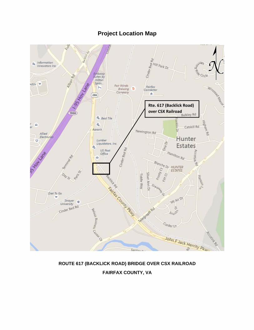
Project Location Map
ROUTE 617 (BACKLICK ROAD) BRIDGE OVER CSX RAILROAD
FAIRFAX COUNTY, VA
Rte. 617 (Backlick Road)
over CSX Railroad

ATTACHMENT 2
STAGE I PRELIMINARY ROADWAY SKETCHES
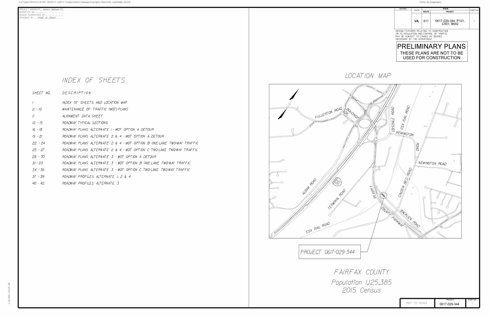
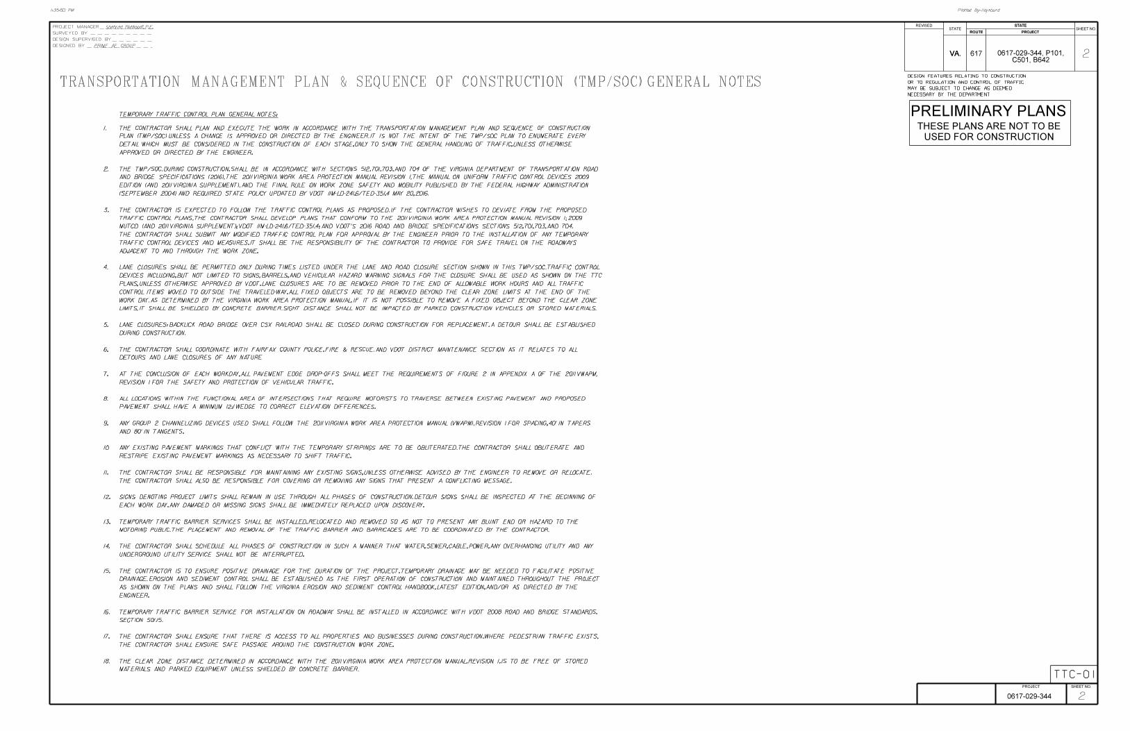
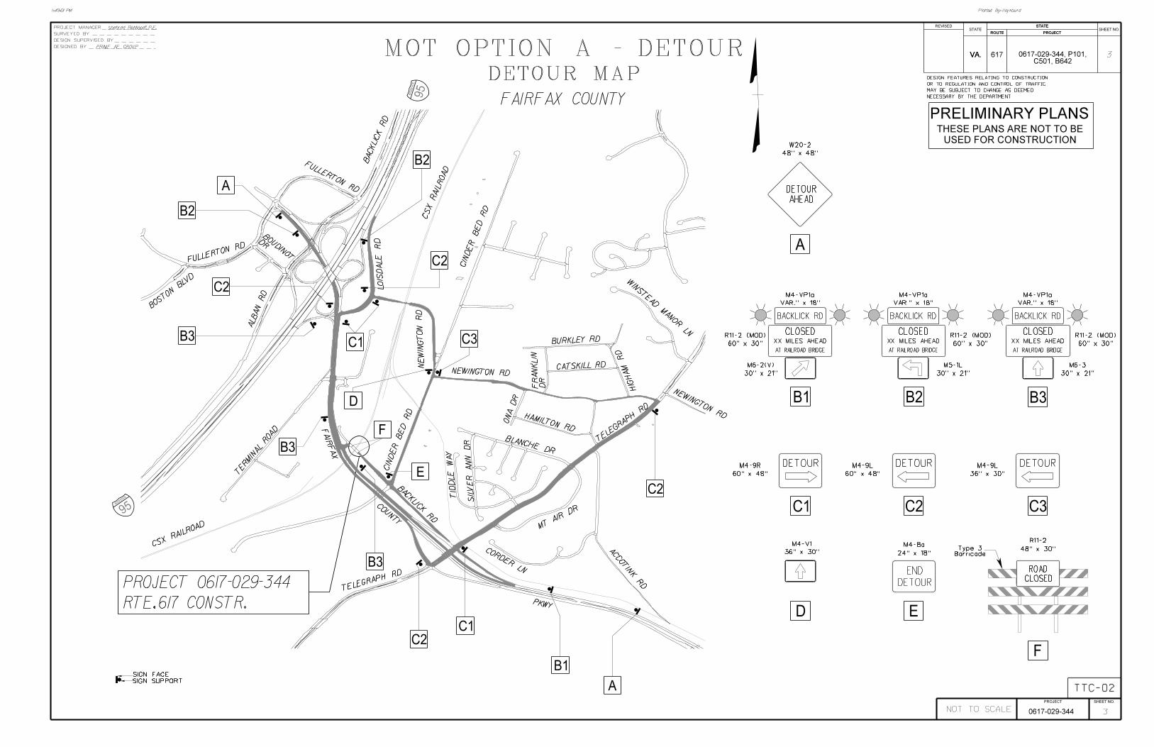
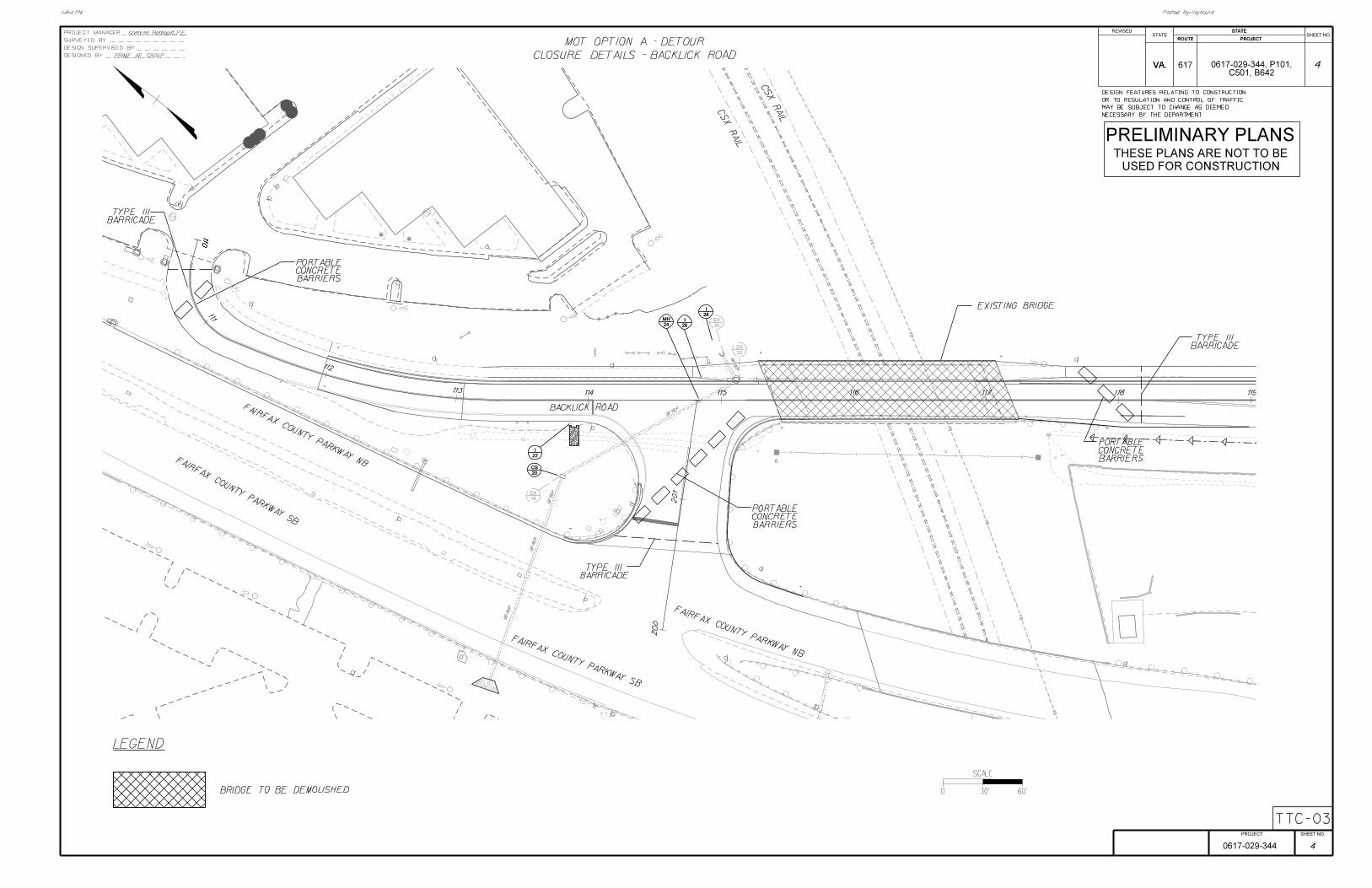
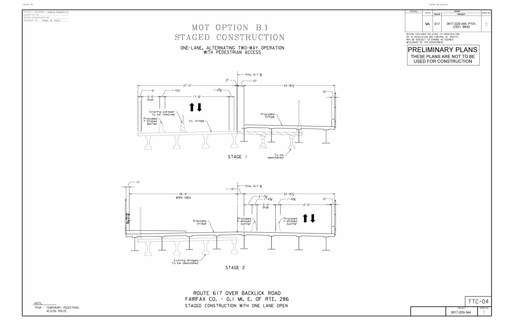
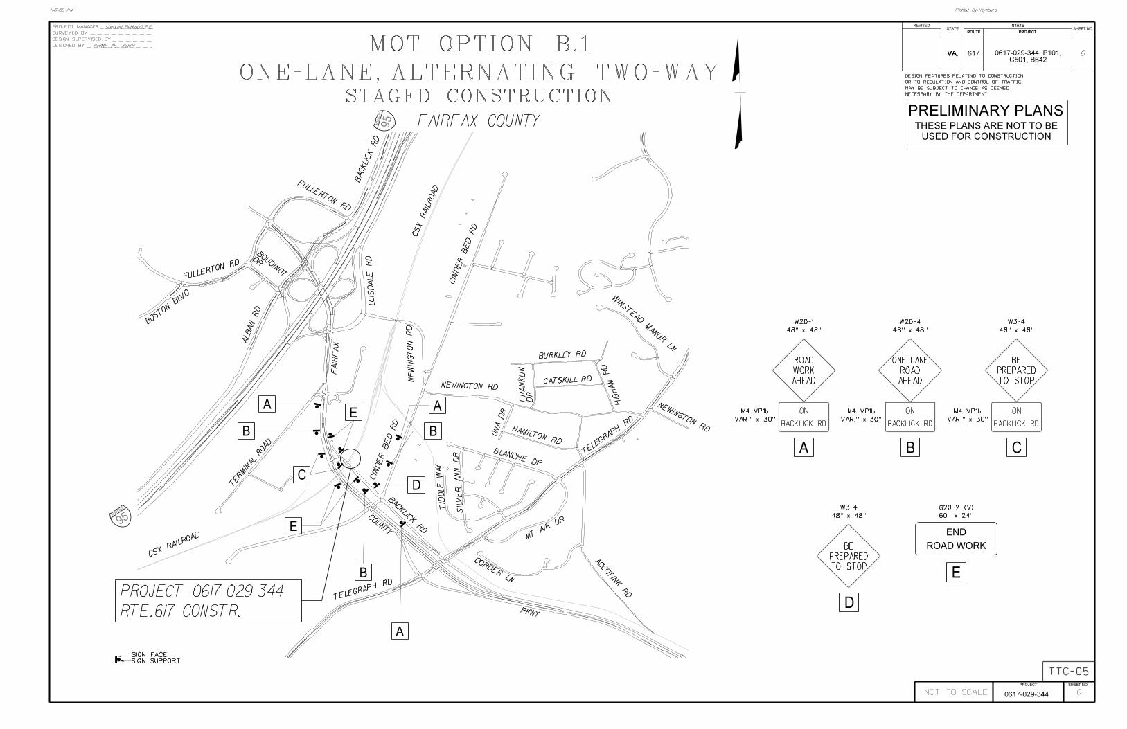


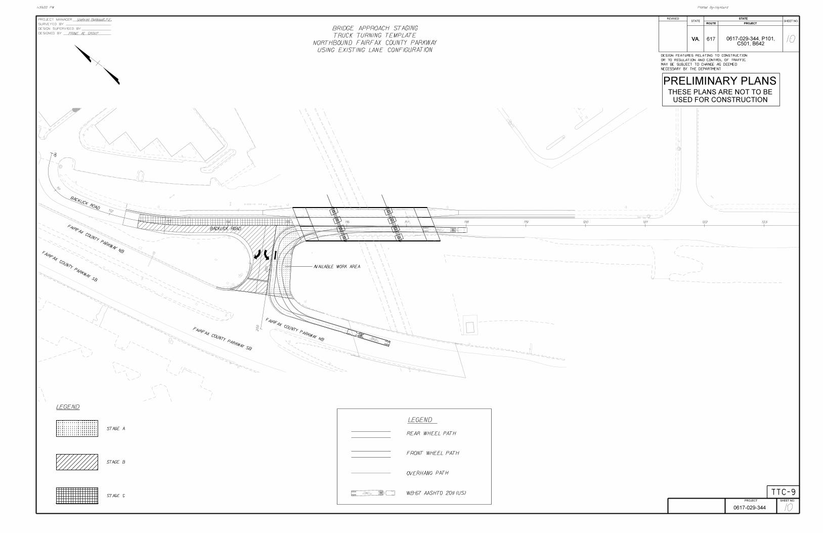
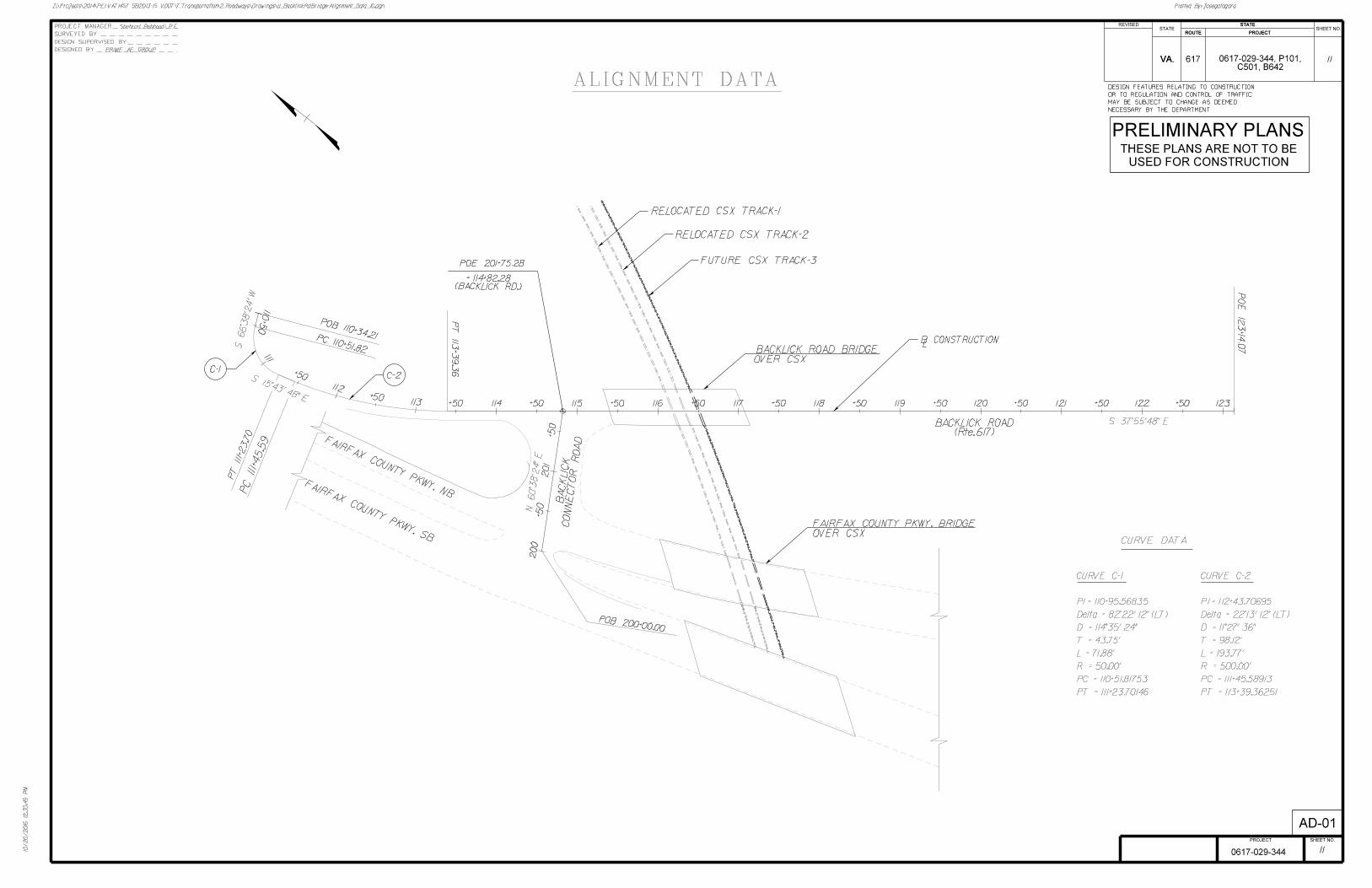
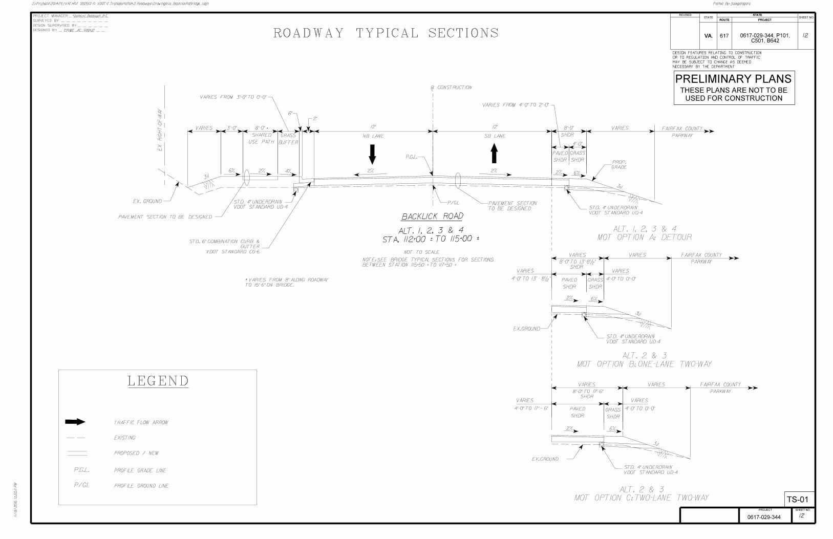

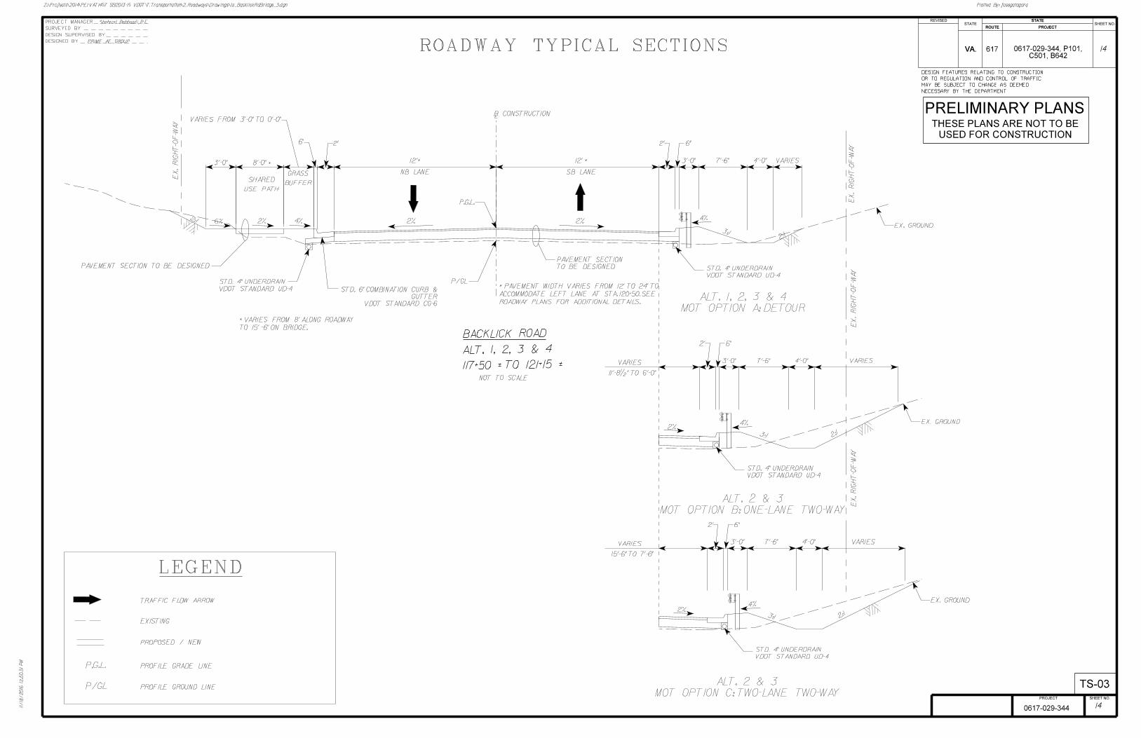
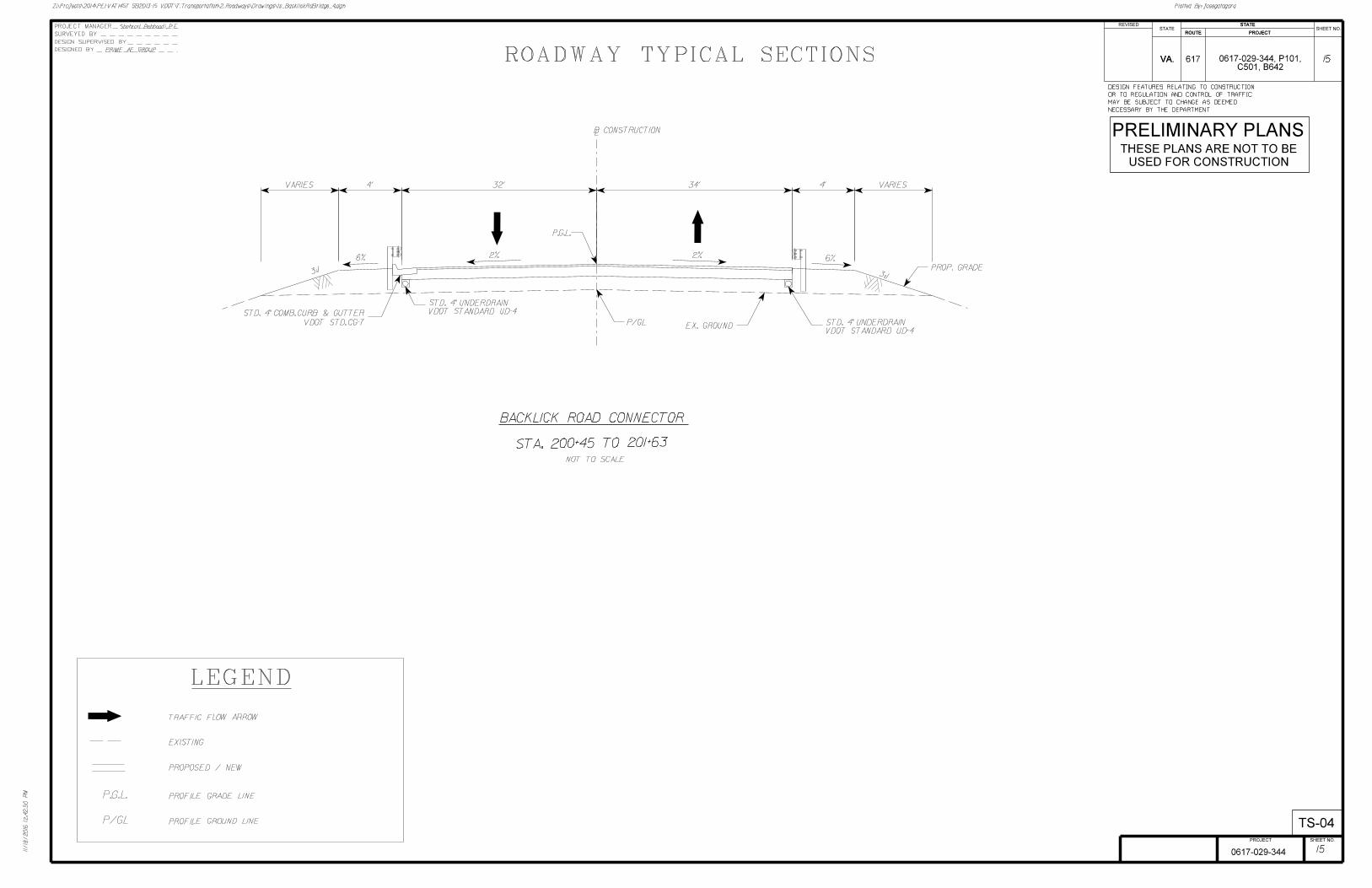
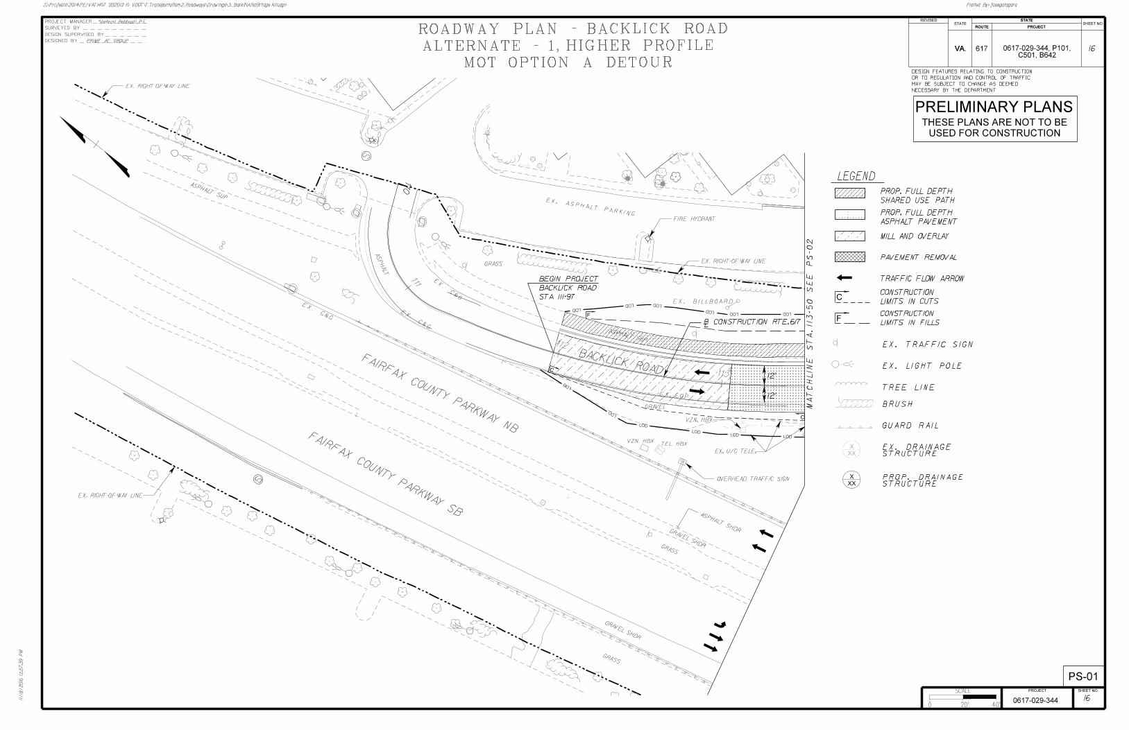


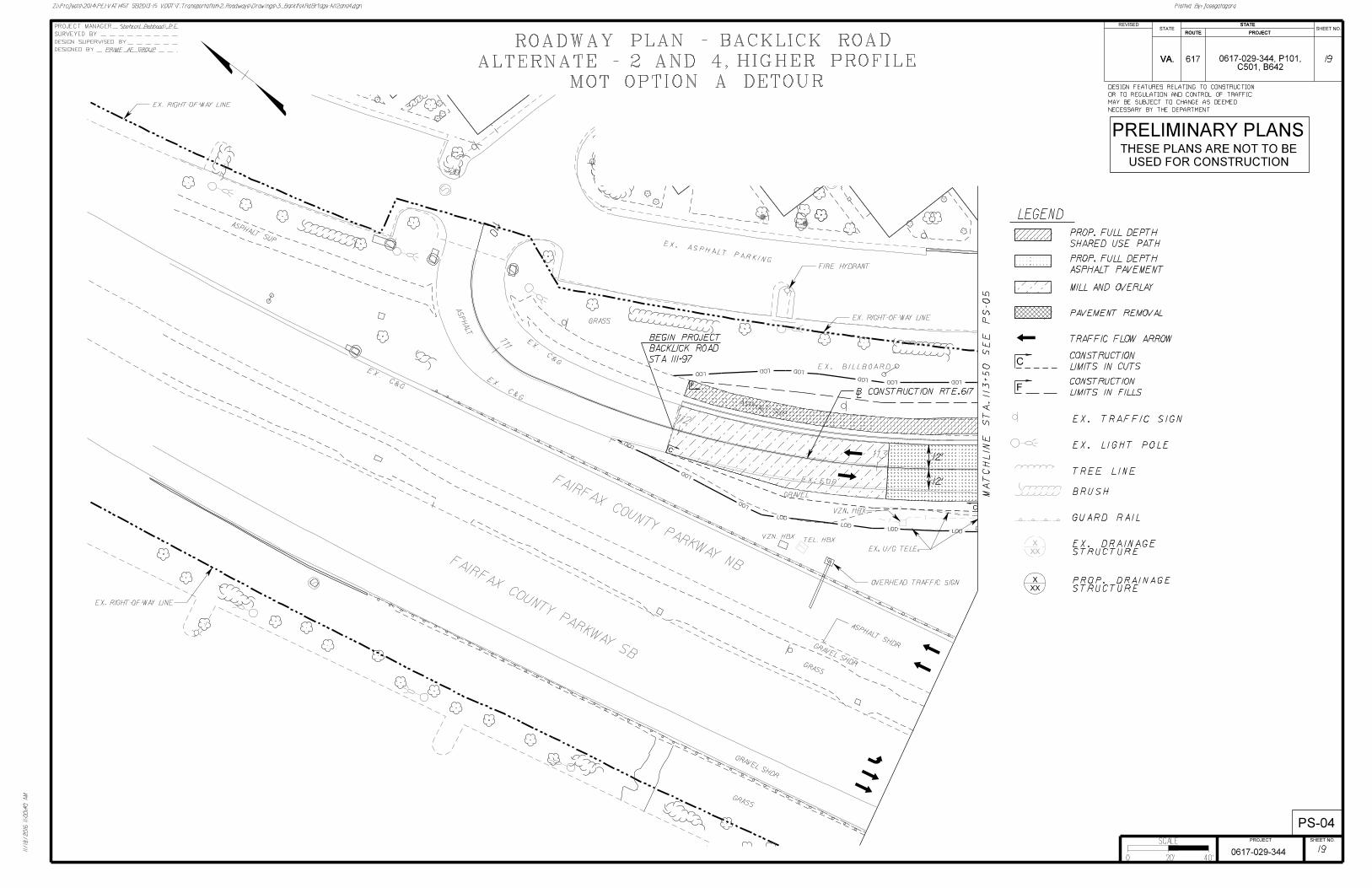
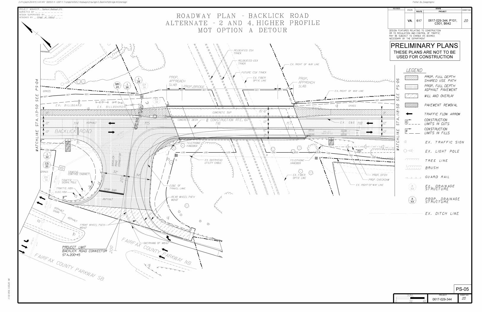


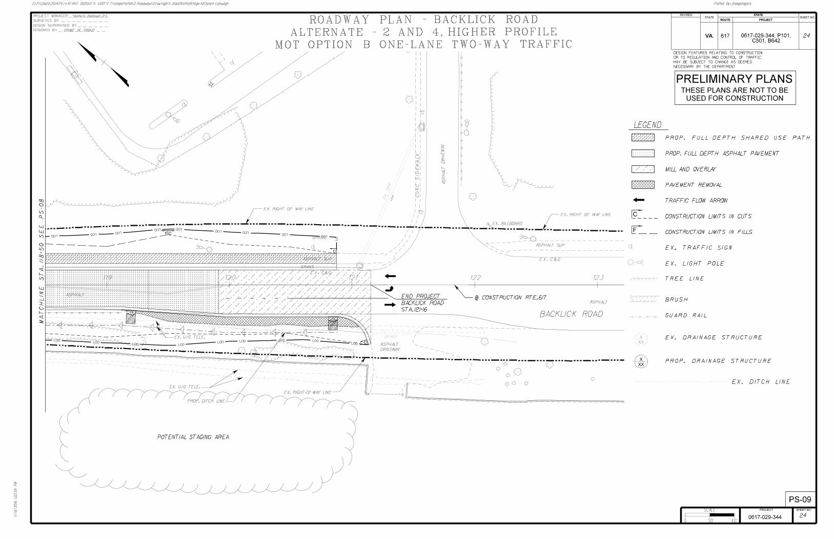
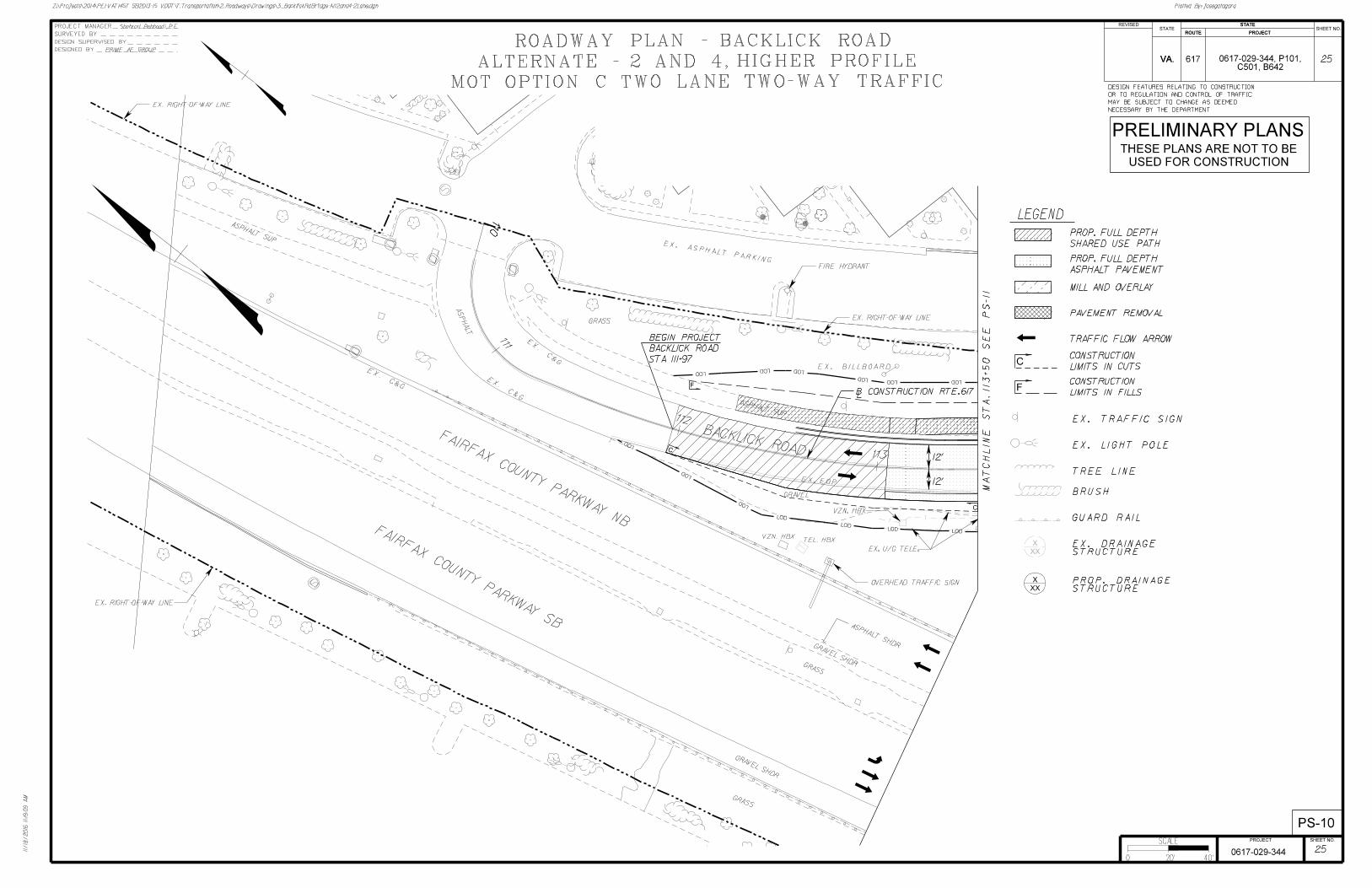

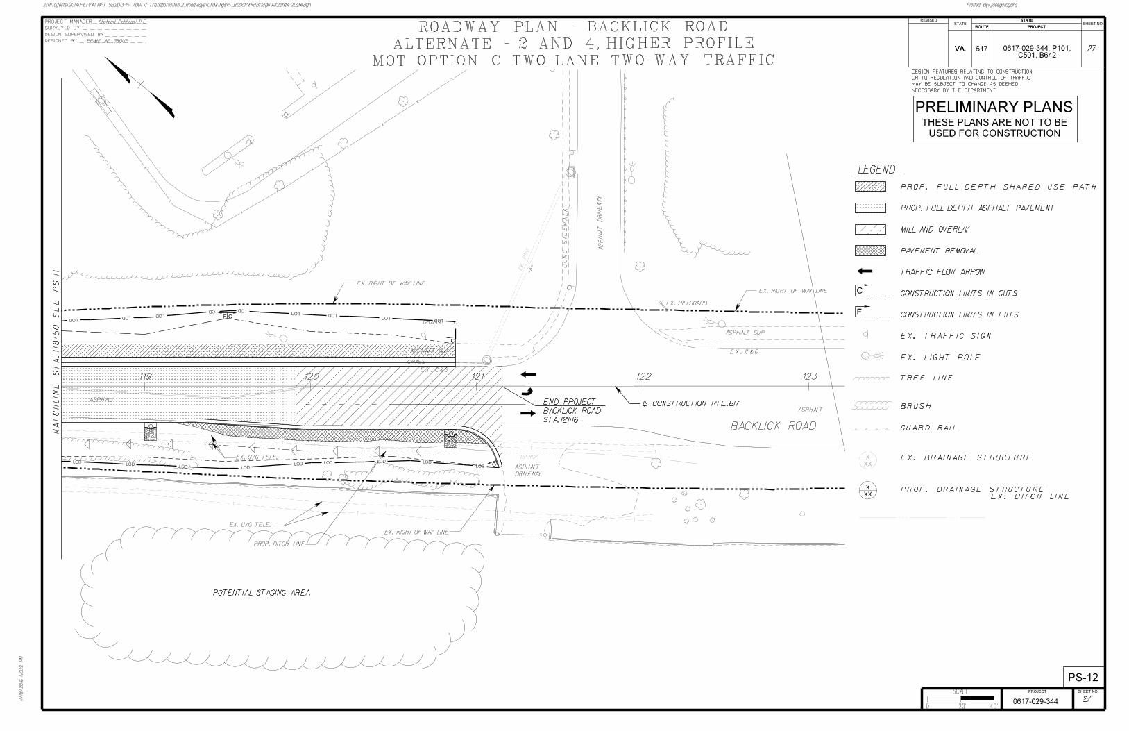

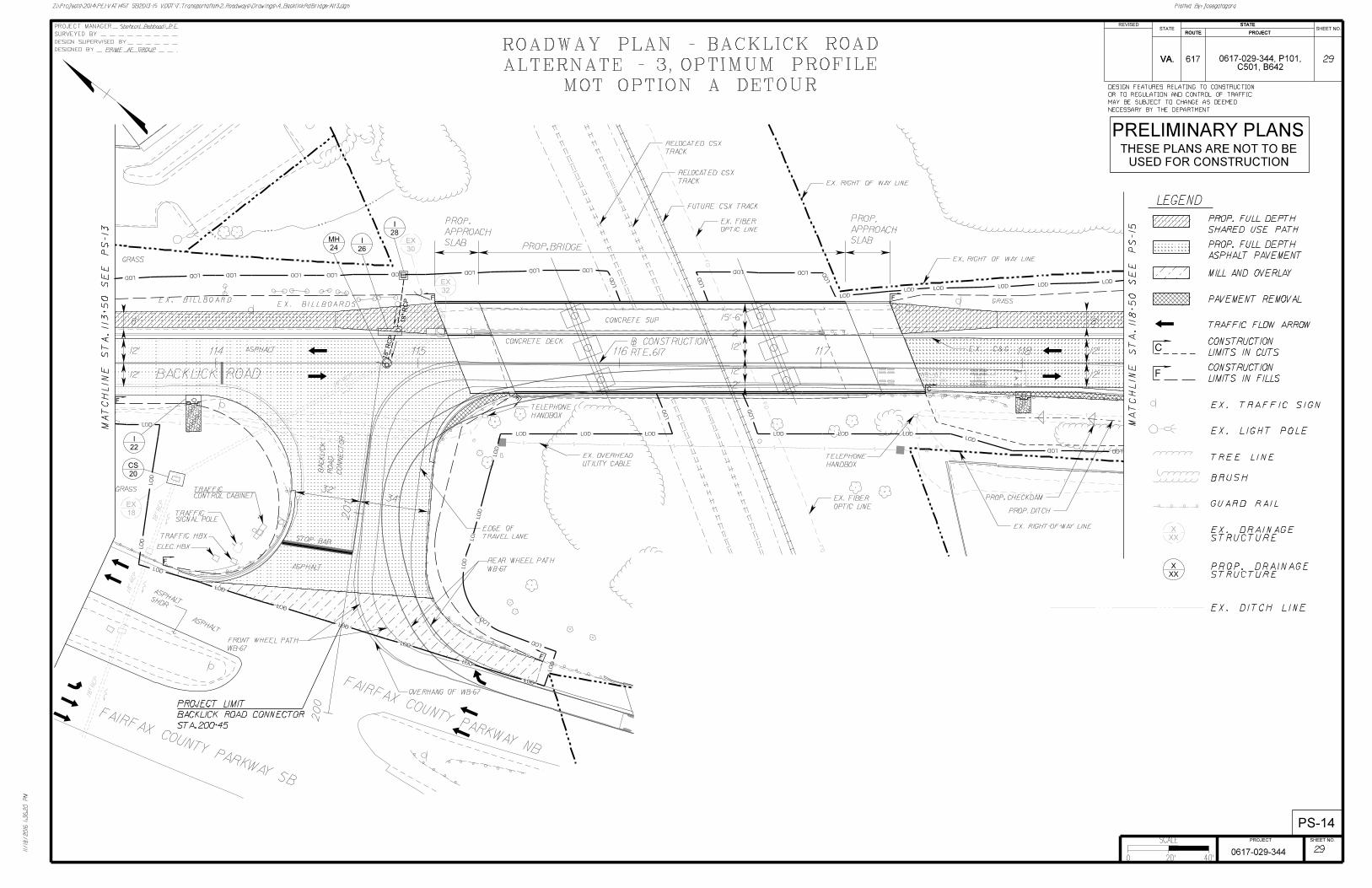
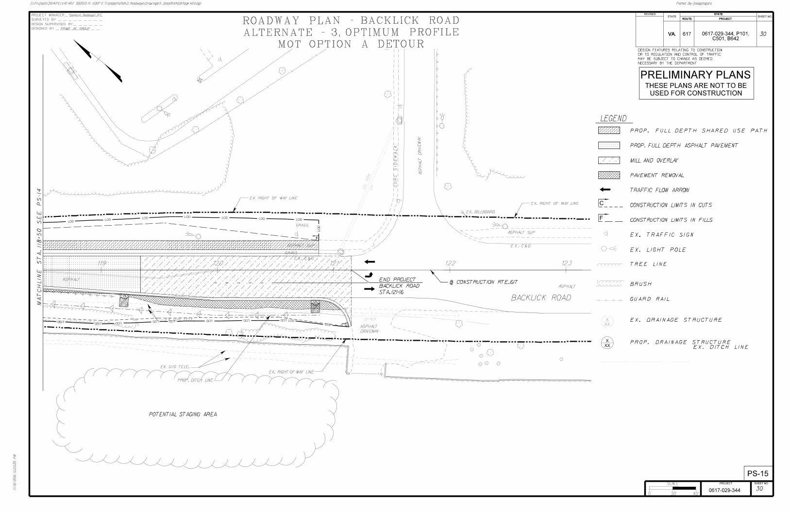
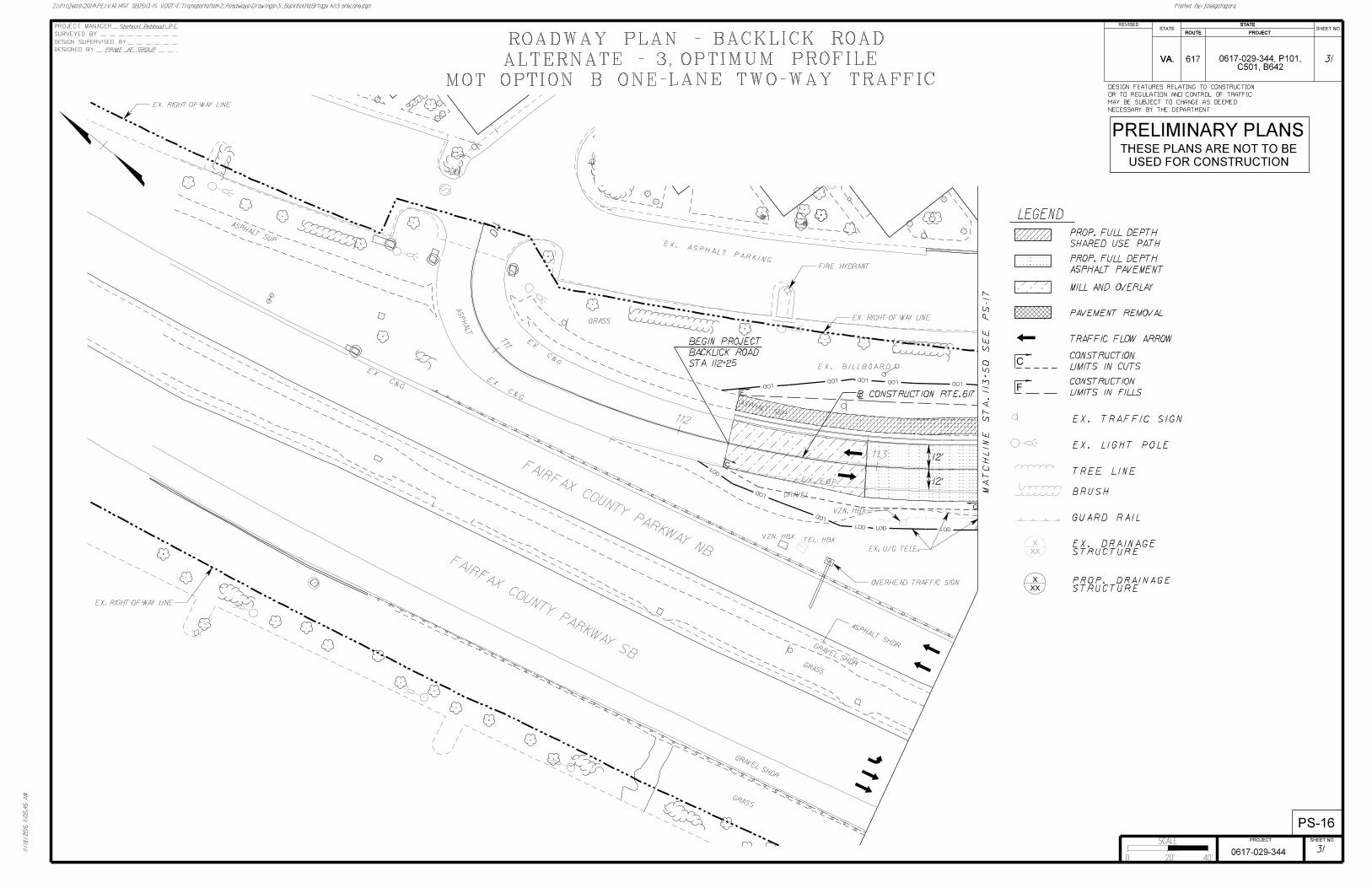


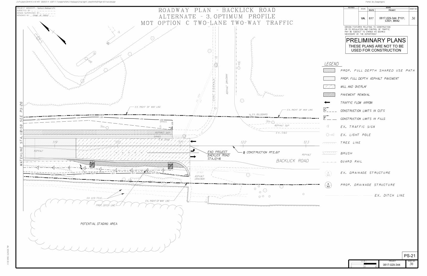
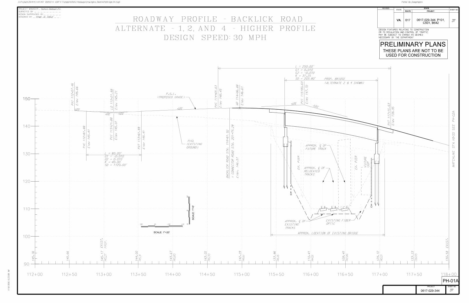

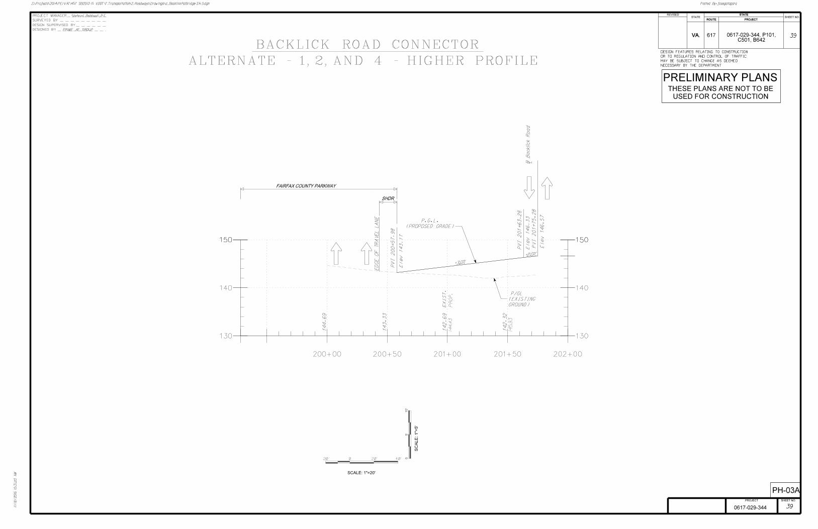
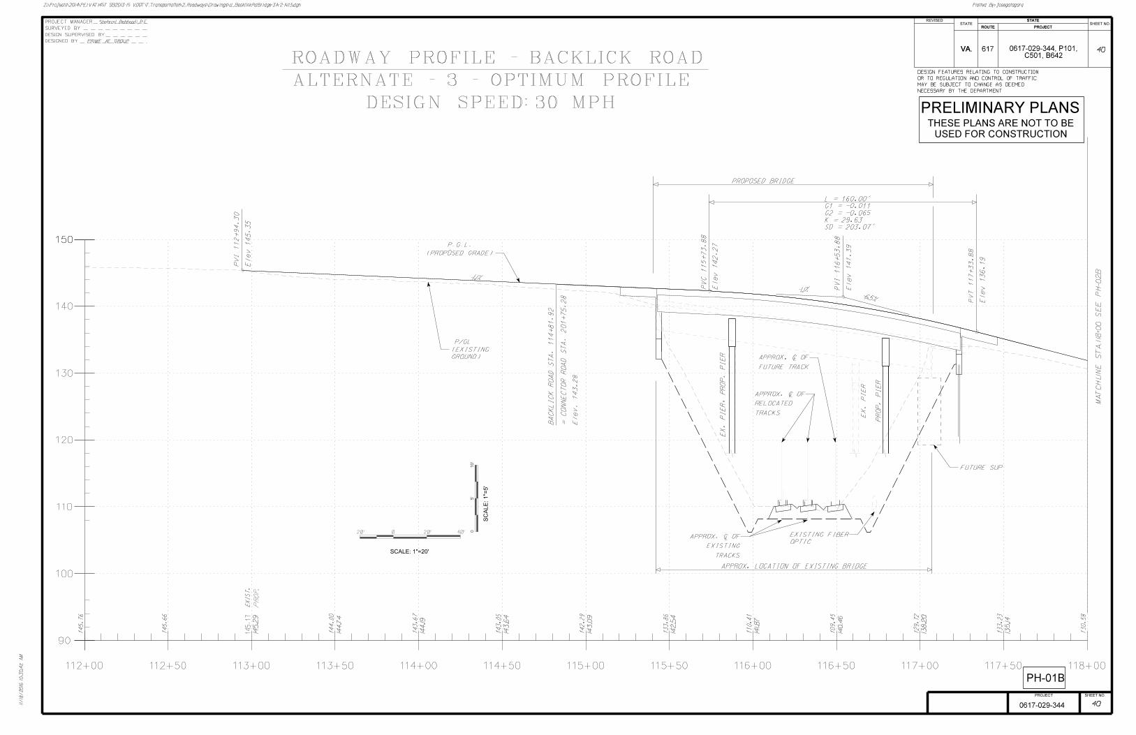
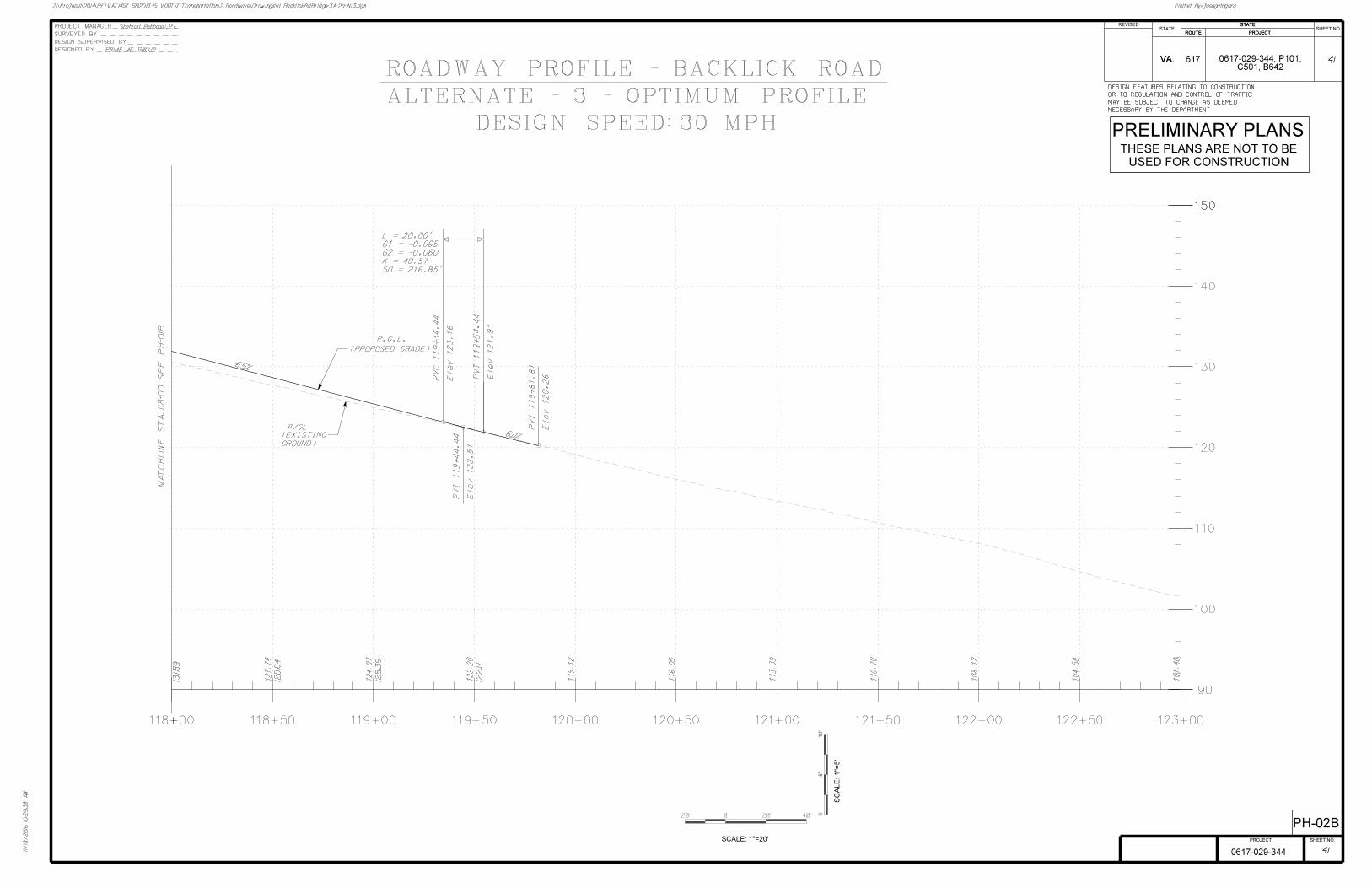
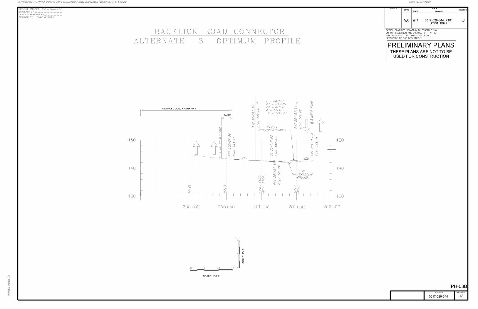
ATTACHMENT 3
STAGE I PRELIMINARY BRIDGE SKETCHES

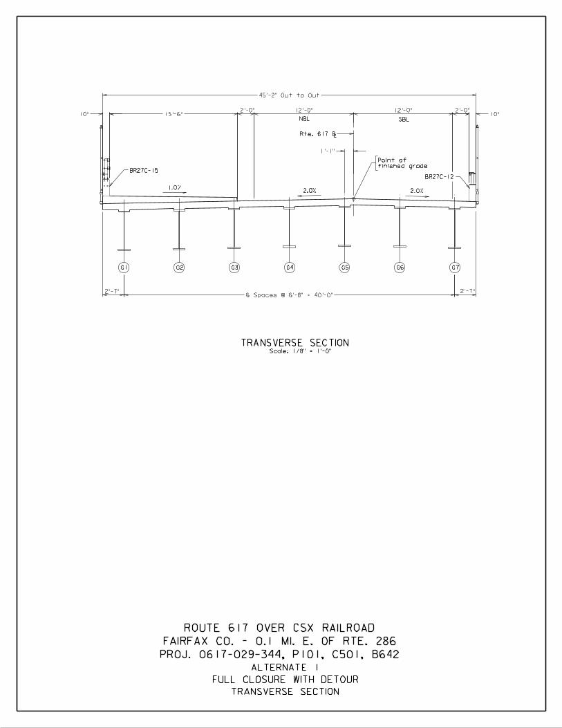
2.0% 2.0%
BR27C-12
TRANSVERSE SECTION
G1 G2 G3 G4 G5 G6
Scale: 1/8" = 1'-0"
G7
Rte. 617 BL
finished grade
Point of
SBLNBL
1.0%
BR27C-15
TRANSVERSE SECTION
ALTERNATE 1
FULL CLOSURE WITH DETOUR
2'-7"2'-7"6 Spaces @ 6'-8" = 40'-0"
1'-1"
12'-0" 2'-0"15'-6"
2'-0" 12'-0"10"10"
45'-2" Out to Out
PROJ. 0617-029-344, P101, C501, B642
FAIRFAX CO. - 0.1 MI. E. OF RTE. 286
ROUTE 617 OVER CSX RAILROAD

115 116 117+50+50 +50
PO
E 202+45.4
8
(BA
CKLIC
K R
D.)
= 114+72.4
8
PLANScale: 1" = 40'-0"
Scale: 1" = 40'-0"
ELEVATION
To Rte. 286 To Cinder Bed Road
15'-0
"
Rte. 617 Constr. B
L
L
L
14'-1
„" +
L
135'-0"
Sta. 116+96.99
Abutment B
End of slab
Sta. 115+61.99
Abutment A
End of slab
145.50
Elev.
28'-
0"
10"
typ.
Approach slab
typ.
22'-0"
Fill
typ.
Approach slab
ABUTMENT B
Fill
LLC Future track
L
L
typ.
HP 12x53
1
2
42'-6
†"
35'-2
‚"
Horiz.
Clear
ance
Horiz. Clr.
ABUTMENT A
139.21
Elev.
10"
43'-
6"
15'-
6"
Face of rail
sidewalk curb
Face of
Face of rail
135'-0"
CSXT R/W
CSXT R/WCSXT R/W
Easement
VDOT
RW-A
MSE Wall RW-B
MSE Wall
mile
post 95
0.1
4
mile to
V.C. = 250.0
C.G. Elev. 147.70
C.G. Sta. 115 + 90.63
C Future relocated track
1.0% -7.0%
Future finished grade
Finished Grade
CSX RR track
C Future
22-00'-0
0"
typ.
Existing Grade
Rte. 617 Constr. B
Existing profile along
PLAN AND ELEVATION
FULL CLOSURE WITH DETOUR
ALTERNATE 2A
to be removed
Existing bridge
to be relocated
CSX RR track
C Existing
CSX RR track
C Future reloc.
Future SUP
Potential
Sta. 115+61.99
Beginning of bridge
End of slab
Sta. 116+96.99
End of bridge
End of slab
18'-0"(w) x 24'-3"(h)
CSX Clearance box
L C track
Existing
PROJ. 0617-029-344, P101, C501, B642
FAIRFAX CO. - 0.1 MI. E. OF RTE. 286
ROUTE 617 OVER CSX RAILROAD
fiber optic cable
Existing underground
optic cable
Existing fiber
Approx. loc. of
proposed grade, typ.
columns to 3'-0" below
Cut and remove pier
Influence Zone
Theoretical Live Load
Influence Zone
Theoretical Live Load
CSXT R/W
clearance provided
25'-5" Min. vert.
clearance required
24'-3" Min. vert.
CSXT R/W

BR27C-12
2.0%2.0%
TRANSVERSE SECTION
G1 G2 G3 G4 G5 G6
Scale: 1/8" = 1'-0"
Rte. 617 BL
finished grade
Point of
BR27C-15
1.0%
SBLNBL
TRANSVERSE SECTION
ALTERNATE 2A
FULL CLOSURE WITH DETOUR
3'-0" 3'-0"
5 Spaces @ 7'-10" = 39'-2"
3'-10"
12'-0" 2'-0"15'-6"
2'-0" 12'-0"10"10"
45'-2" Out to Out
PROJ. 0617-029-344, P101, C501, B642
FAIRFAX CO. - 0.1 MI. E. OF RTE. 286
ROUTE 617 OVER CSX RAILROAD
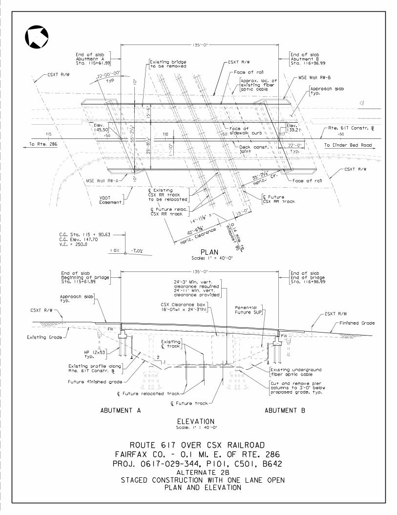
115 116 117+50+50 +50
PO
E 202+45.4
8
(BA
CKLIC
K R
D.)
= 114+72.4
8
PLANScale: 1" = 40'-0"
To Rte. 286 To Cinder Bed Road
Rte. 617 Constr. BL
135'-0"
Sta. 116+96.99
Abutment B
End of slab
Sta. 115+61.99
Abutment A
End of slab
145.50
Elev.
10"
typ.
Approach slab
typ.
22'-0"
139.21
Elev.
39'-
8•
"15'-
6"
55'-
2•
"10"
Face of rail
sidewalk curb
Face of
joint
Deck const.
typ.
HP 12x53
LC Future relocated track
Scale: 1" = 40'-0"
ELEVATION
ABUTMENT B
LLC Future track
ABUTMENT A
Fill
Fill
22-00'-0
0"
typ.
CSXT R/W
Face of rail
CSXT R/W
LCSX RR track
C Future
35'-2
‚"
Horiz. Clr.
15'-0
"
mile
post 95
0.1
4
mile to
14'-1
„" +
42'-6
†"
Horiz.
Clear
ance
CSX RR track
C Future reloc.
Easement
VDOT
to be relocated
CSX RR track
C ExistingL
CSXT R/W
MSE Wall RW-B
MSE Wall RW-A
L
V.C. = 250.0
C.G. Elev. 147.70
C.G. Sta. 115 + 90.63
1.0% -7.0%
Existing Grade
PLAN AND ELEVATION
STAGED CONSTRUCTION WITH ONE LANE OPEN
ALTERNATE 2B
1'-
10"
to be removed
Existing bridge
L
Future finished grade
Rte. 617 Constr. B
Existing profile along
1
2
L C track
Existing
PROJ. 0617-029-344, P101, C501, B642
FAIRFAX CO. - 0.1 MI. E. OF RTE. 286
ROUTE 617 OVER CSX RAILROAD
fiber optic cable
Existing underground
optic cable
existing fiber
Approx. loc. of
proposed grade, typ.
columns to 3'-0" below
Cut and remove pier
typ.
Approach slab
135'-0"
Future SUP
Potential
Sta. 115+61.99
Beginning of bridge
End of slab
Sta. 116+96.99
End of bridge
End of slab
18'-0"(w) x 24'-3"(h)
CSX Clearance box
CSXT R/W
Finished Grade
CSXT R/W
clearance provided
24'-11" Min. vert.
clearance required
24'-3" Min. vert.
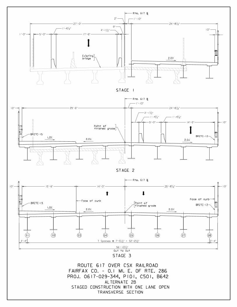
TRANSVERSE SECTION
STAGE 3
STAGE 1
STAGE 2
Rte. 617 BL
2.0%
Rte. 617 BL
2.0% 2.0%
BR27C-12
Rte. 617 BL
Face of curb
2.0% 2.0%
BR27C-12
Face of curb
G1 G2 G3 G4 G5 G6 G7 G8
Out to Out
finished grade
Point of
finished grade
Point of
STAGED CONSTRUCTION WITH ONE LANE OPEN
BR27C-15
BR27C-15
1.0%
1.0%
ALTERNATE 2B
bridge
Existing
27'-0"
17'-6"5'-0"
4'-1•"
24'-8•"
10"
2"
24'-8•"29'-6"
14'-0"5'-0"
1'-4•"
1'-10"
10"
1'-4•"
1'-4•"
10"
15'-6" 14'-0" 25'-8•"10"
56'-10•"
10"
7 Spaces @ 7'-5•" = 52'-2•"
2'-1•"
1'-0"
1'-10"
2'-4" 2'-4"
9"
PROJ. 0617-029-344, P101, C501, B642
FAIRFAX CO. - 0.1 MI. E. OF RTE. 286
ROUTE 617 OVER CSX RAILROAD

115 116 117+50+50 +50
PO
E 202+45.4
8
(BA
CKLIC
K R
D.)
= 114+72.4
8
PLANScale: 1" = 40'-0"
To Rte. 286 To Cinder Bed Road
Rte. 617 Constr. BL
135'-0"
Sta. 116+96.99
Abutment B
End of slab
Sta. 115+61.99
Abutment A
End of slab
145.50
Elev.
typ.
Approach slab
typ.
22'-0"
35'-2
‚"
Horiz. Clr.
139.21
Elev.
59'-
0"
15'-
6"
43'-
6"
Face of rail
sidewalk curb
Face of
joint
Deck const.
3'-
11"
CSXT R/W 22-00'-0
0"
typ.
Easement
VDOT
to be relocated
CSX RR track
C ExistingL
L CSX RR track
C Future reloc.
15'-0
"
mile
post 95
0.1
4
mile to
42'-6
†"
Horiz.
Clear
ance
14'-1
„" +
CSXT R/W
V.C. = 250.0
C.G. Elev. 147.70
C.G. Sta. 115 + 90.63
1.0% -7.0%
typ.
HP 12x53
Fill
LC Future relocated track
ELEVATION
ABUTMENT B
LLC Future track
ABUTMENT A
Scale: 1" = 40'-0"
Fill
10"
10"
MSE Wall RW-A
Face of rail
CSXT R/W
LCSX RR track
C Future
MSE Wall RW-B
Existing Grade
PLAN AND ELEVATION
STAGED CONSTRUCTION WITH TWO LANES OPEN
ALTERNATE 2C
to be removed
Existing bridge
L C track
Existing
1
2
L
Future finished grade
Rte. 617 Constr. B
Existing profile along
PROJ. 0617-029-344, P101, C501, B642
FAIRFAX CO. - 0.1 MI. E. OF RTE. 286
ROUTE 617 OVER CSX RAILROAD
fiber optic cable
Existing underground
optic cable
existing fiber
Approx. loc. of
proposed grade, typ.
columns to 3'-0" below
Cut and remove pier
Finished Grade
CSXT R/W
typ.
Approach slab
135'-0"
Sta. 115+61.99
Beginning of bridge
End of slab
Sta. 116+96.99
End of bridge
End of slab
Future SUP
Potential 18'-0"(w) x 24'-3"(h)
CSX Clearance box
CSXT R/W
clearance provided
24'-10" Min. vert.
clearance required
24'-3" Min. vert.

STAGE 3
STAGE 2
STAGE 1
Rte. 617 BL
2.0%
2.0%
2.0%2.0%
2.0%
BR27C-12
BR27C-12
G1 G2 G3 G4 G5 G6 G7 G8
Rte. 617 BL
Rte. 617 BL
Out to Out
Face of curb
Face of curb
finished grade
Point of
finished grade
Point of
TRANSVERSE SECTION
STAGED CONSTRUCTION WITH TWO LANES OPEN
BR27C-15
1.0%
1.0%
1'-0"
10"
ALTERNATE 2C
bridge
Existing
PROJ. 0617-029-344, P101, C501, B642
FAIRFAX CO. - 0.1 MI. E. OF RTE. 286
ROUTE 617 OVER CSX RAILROAD
26'-5"27'-0"
11'-0"11'-0"
11'-0"11'-0"
15'-6" 14'-0" 29'-6"
2"
3'-11"
10"
10"10"
60'-8"
1'-4•"
1'-4•"
1'-4•"
1'-0" 1'-0"
29'-6"3'-11"
26'-5"
10"
1'-0"
7 Spaces @ 7'-10" = 54'-10"2'-11"2'-11"
3"
2•"
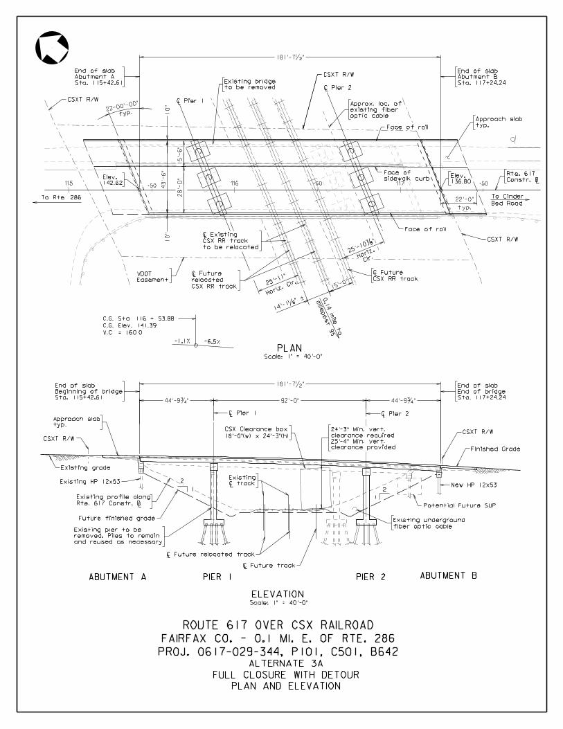
115 116 117+50+50 +50
PO
E 202+45.4
8
(BA
CKLIC
K R
D.)
= 114+72.4
8
PLANScale: 1" = 40'-0"
Scale: 1" = 40'-0"
ELEVATION
To Rte. 286
15'-0
"
L
L
to be relocated
CSX RR track
C Existing
14'-1
„" +
LCSX RR track
C Future
28'-
0"
10"
typ.
Approach slab
ABUTMENT B
Sta. 115+42.61
Abutment A
End of slab
142.62
Elev.
Sta. 117+24.24
Abutment B
End of slab
typ.
22'-0"
136.80
Elev.
LConstr. B
Rte. 617
Bed Road
To Cinder
Horiz.
Clr.
Clr.Ho
riz.
LC Pier 1
ABUTMENT A
92'-0"44'-9ƒ" 44'-9ƒ"
LC Pier 1LC Pier 2
1
2
LLC Future track
2
1
25'-1
1"
25'-1
0‡"
10"
43'-
6"
15'-
6"
Face of rail
sidewalk curb
Face of
CSXT R/W
Easement
VDOT
CSXT R/W
Face of rail
mile
post 95
0.1
4
mile to
typ.
22-00'-0
0"
CSX RR track
relocated
C Future
Rte. 617 Constr. B
Existing profile along
L
Future finished grade
LC Future relocated track
Potential Future SUP
Finished Grade
Existing grade
V.C. = 160.0
C.G. Elev. 141.39
C.G. Sta. 116 + 53.88
-6.5%
CSXT R/W
LC Pier 2
-1.1%
PIER 1 PIER 2
PLAN AND ELEVATION
FULL CLOSURE WITH DETOUR
ALTERNATE 3A
181'-7•"
to be removed
Existing bridge
181'-7•"
Sta. 115+42.61
Beginning of bridge
End of slab
Sta. 117+24.24
End of bridge
End of slab
18'-0"(w) x 24'-3"(h)
CSX Clearance box
L C track
Existing
fiber optic cable
Existing underground
and reused as necessary
removed. Piles to remain
Existing pier to be
Existing HP 12x53 New HP 12x53
PROJ. 0617-029-344, P101, C501, B642
FAIRFAX CO. - 0.1 MI. E. OF RTE. 286
ROUTE 617 OVER CSX RAILROAD
optic cable
existing fiber
Approx. loc. of
CSXT R/W
typ.
Approach slab
CSXT R/W
clearance provided
25'-4" Min. vert.
clearance required
24'-3" Min. vert.
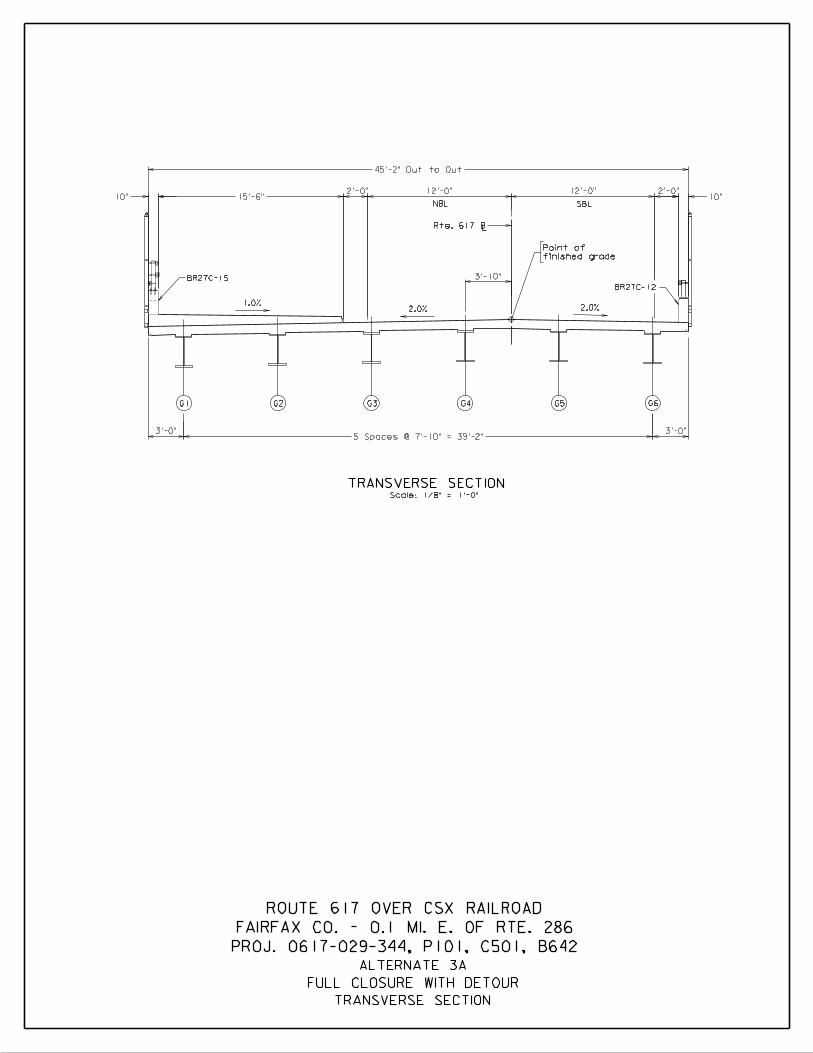
2.0%
BR27C-12
2.0%
TRANSVERSE SECTION
G1 G2 G3 G4 G5 G6
Scale: 1/8" = 1'-0"
Rte. 617 BL
finished grade
Point of
SBLNBL
1.0%
BR27C-15
TRANSVERSE SECTION
ALTERNATE 3A
FULL CLOSURE WITH DETOUR
3'-0" 3'-0"5 Spaces @ 7'-10" = 39'-2"
3'-10"
12'-0" 2'-0"15'-6"
2'-0" 12'-0"10"10"
45'-2" Out to Out
PROJ. 0617-029-344, P101, C501, B642
FAIRFAX CO. - 0.1 MI. E. OF RTE. 286
ROUTE 617 OVER CSX RAILROAD
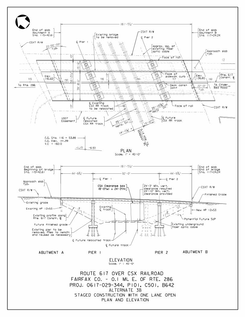
115 116 117+50+50 +50
PO
E 202+45.4
8
(BA
CKLIC
K R
D.)
= 114+72.4
8
Scale: 1" = 40'-0"
ELEVATION
To Rte. 286
L
to be relocated
CSX RR track
C Existing
LCSX RR track
C Future
typ.
Approach slab
Sta. 115+42.61
Abutment A
End of slab
142.62
Elev.
Sta. 117+24.24
Abutment B
End of slab
typ.
22'-0"
136.80
Elev.
LConstr. B
Rte. 617
Bed Road
To Cinder
LC Pier 1
LLC Future track
2
1
25'-1
0‡"
15'-
6"
Face of rail
sidewalk curb
Face of
55'-
2•
"
39'-
8•
"
joint
Deck const.
15'-0
"
mile
post 95
0.1
4
mile to
14'-1
„" +
Horiz.
Clr.25
'-11"
L
CSX RR track
relocated
C Future
Easement
VDOT
CSXT R/W
typ.
22-00'-0
0"CSXT R/W
10"
10"
Existing grade
LC Future relocated track
Finished Grade
92'-0"44'-9ƒ" 44'-9ƒ"
LC Pier 1LC Pier 2
PLANScale: 1" = 40'-0"
1'-
10"
CSXT R/W
LC Pier 2
Face of rail
V.C. = 160.0
C.G. Elev. 141.39
C.G. Sta. 116 + 53.88
-6.5%-1.1%
ABUTMENT BABUTMENT A PIER 1 PIER 2
Potential Future SUP
PLAN AND ELEVATION
STAGED CONSTRUCTION WITH ONE LANE OPEN
ALTERNATE 3B
Horiz. Clr.
181'-7•"
to be removed
Existing bridge
Sta. 115+42.61
Beginning of bridge
End of slab 181'-7•"
Sta. 117+24.24
End of bridge
End of slab
18'-0"(w) x 24'-3"(h)
CSX Clearance box
L C track
Existing
Rte. 617 Constr. B
Existing profile along
Future finished grade
and reused as necessary
removed. Piles to remain
Existing pier to be
Existing HP 12x53
L
1
2New HP 12x53
fiber optic cable
Existing underground
PROJ. 0617-029-344, P101, C501, B642
FAIRFAX CO. - 0.1 MI. E. OF RTE. 286
ROUTE 617 OVER CSX RAILROAD
optic cable
existing fiber
Approx. loc. of
CSXT R/W
typ.
Approach slab
18'-0"(w) x 24'-3"(h)
CSX Clearance box CSXT R/W
clearance provided
24'-10" Min. vert.
clearance required
24'-3" Min. vert.

TRANSVERSE SECTION
STAGE 3
G1 G2 G3 G4 G5 G6 G7 G8
Out to Out
STAGED CONSTRUCTION WITH ONE LANE OPEN
ALTERNATE 3B
Rte. 617 BL
BR27C-15
1.0%2.0%
Face of curb
finished grade
Point of
2.0%
BR27C-12
Face of curb
STAGE 2
Rte. 617 BL
BR27C-12
2.0%
finished grade
Point of
2.0%
BR27C-15
1.0%
STAGE 1
2.0%
Rte. 617 B
56'-10•"
7 Spaces @ 7'-5•" = 52'-2•"2'-4" 2'-4"
15'-6" 14'-0" 25'-8•"10" 10"
24'-8•"
14'-0"5'-0"
1'-4•"
1'-10"
1'-4•"
2'-1•"
10"
29'-6"10"
24'-8•"
10"
2" 1'-10"
27'-0"
17'-6"5'-0"
1'-4•"1'-4•"
1'-0"
bridge
Existing
PROJ. 0617-029-344, P101, C501, B642
FAIRFAX CO. - 0.1 MI. E. OF RTE. 286
ROUTE 617 OVER CSX RAILROAD
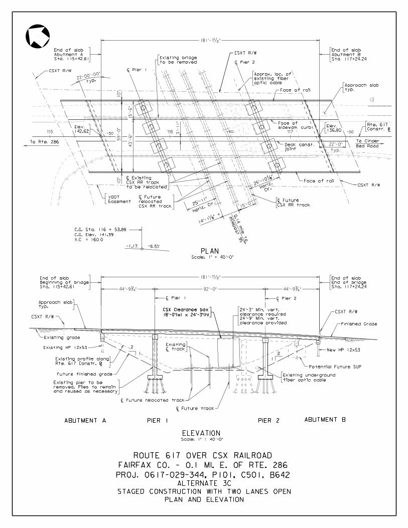
115 116 117+50+50 +50
PO
E 202+45.4
8
(BA
CKLIC
K R
D.)
= 114+72.4
8
PLANScale: 1" = 40'-0"
To Rte. 286
L
to be relocated
CSX RR track
C Existing
LCSX RR track
C Future
typ.
Approach slab
Sta. 115+42.61
Abutment A
End of slab
142.62
Elev.
Sta. 117+24.24
Abutment B
End of slab
typ.
22'-0"
136.80
Elev.
LConstr. B
Rte. 617
Bed Road
To Cinder
Clr.Ho
riz.
LC Pier 1
2
1
25'-1
0‡"
10"
15'-
6"
Face of rail
Face of rail
sidewalk curb
Face of
59'-
0"
43'-
6"
joint
Deck const.
3'-
11"
10"
typ.
22-00'-0
0"CSXT R/W
CSXT R/W
Easement
VDOT
L
CSX RR track
relocated
C Future
Horiz.
Clr.25
'-11"
15'-0
"
mile
post 95
0.1
4
mile to
14'-1
„" +
Existing grade
Finished Grade
CSXT R/W
LC Pier 2
V.C. = 160.0
C.G. Elev. 141.39
C.G. Sta. 116 + 53.88
-6.5%-1.1%
Potential Future SUP
Scale: 1" = 40'-0"
ELEVATION
ABUTMENT BABUTMENT A PIER 1 PIER 2
PLAN AND ELEVATION
STAGED CONSTRUCTION WITH TWO LANES OPEN
ALTERNATE 3C
181'-7•"
to be removed
Existing bridge
L C track
Existing
Rte. 617 Constr. B
Existing profile along
Future finished grade
and reused as necessary
removed. Piles to remain
Existing pier to be
L
Existing HP 12x53
1
2
LC Future relocated track
LLC Future track
fiber optic cable
Existing underground
New HP 12x53
PROJ. 0617-029-344, P101, C501, B642
FAIRFAX CO. - 0.1 MI. E. OF RTE. 286
ROUTE 617 OVER CSX RAILROAD
optic cable
existing fiber
Approx. loc. of
92'-0"44'-9ƒ" 44'-9ƒ"
LC Pier 1LC Pier 2
Sta. 115+42.61
Beginning of bridge
End of slab 181'-7•"
Sta. 117+24.24
End of bridge
End of slab
18'-0"(w) x 24'-3"(h)
CSX Clearance box
CSXT R/W
typ.
Approach slab
18'-0"(w) x 24'-3"(h)
CSX Clearance box CSXT R/W
clearance provided
24'-9" Min. vert.
clearance required
24'-3" Min. vert.
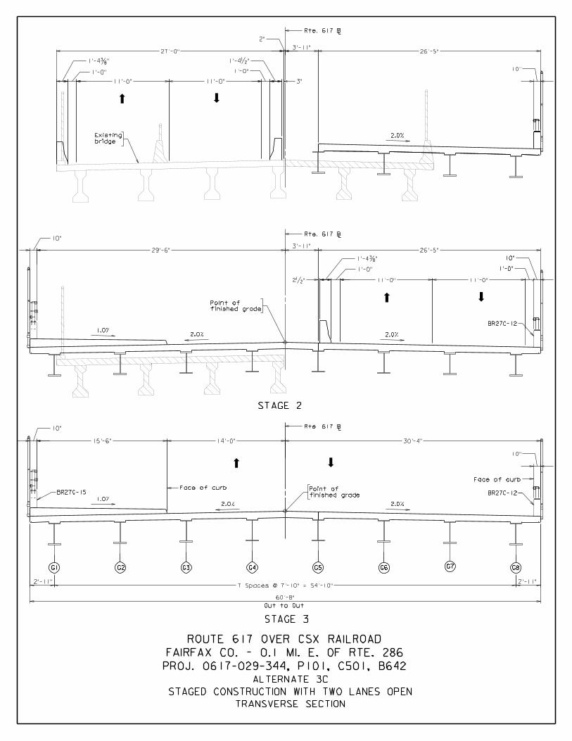
STAGE 3
G1 G2 G3 G4 G5 G6 G7 G8
Out to Out
TRANSVERSE SECTION
STAGED CONSTRUCTION WITH TWO LANES OPEN
ALTERNATE 3C
Rte. 617 BL
2.0%
2.0%
finished grade
Point of
1.0%
Rte. 617 BL
2.0%
BR27C-12
1'-0"
10"
STAGE 2
Rte. 617 BL
BR27C-15
1.0%2.0%
Face of curb
finished grade
Point of
2.0%
BR27C-12
Face of curb
G1 G2 G3 G4 G5 G6 G7 G8
60'-8"
7 Spaces @ 7'-10" = 54'-10"2'-11"
26'-5"27'-0"
2"
3'-11"
1'-4…" 1'-4•"
11'-0"11'-0"
1'-0" 1'-0"
10"
29'-6"
10"
11'-0"
1'-4…"
26'-5"
1'-0"
3'-11"
11'-0"
14'-0" 30'-4"15'-6"
10"
10"
2'-11"
bridge
Existing
3"
2•"
PROJ. 0617-029-344, P101, C501, B642
FAIRFAX CO. - 0.1 MI. E. OF RTE. 286
ROUTE 617 OVER CSX RAILROAD

ATTACHMENT 4
ENGINEER’S COST ESTIMATES

Item Code
60409604506045260490617116181262041620436708862534
Item Code
640056401164112647656476865013652006521167900
Item Code
00100001016847668492
====
=====
LFSY
TNCYLFEALFCYLB
INCIDENTAL ITEMS
Item Quantity Unit Unit Cost Total Item Cost
Sub Total = $329,200
Mobilization LSLS
1 $248,100 $248,100Construction Surveying 1 $35,100 $35,100Environmental and Worker Protection 1 LS $6,000 $6,000Material Disposal
$2.30 $18,470Dismantle and Remove Exst. Struct. 1 $510,000 $510,000
Sub Total = $856,370
LBLS
SUBSTRUCTURE
Item Quantity Unit Unit Cost
$2,891,300$990,800
Steel Piles 12" 1120 $65.00 $72,800
Total Item Cost
Select Matl. Ty. 1 Min. CBR30 1696 $35.00 $59,360Structure Excavation 642 $40.00 $25,680
Concrete Class A3 143.9
Corrosion Resistant Reinf. Steel Cl. I 8030
ROUTE 617 OVER CSX RAILROADFairfax County, NOVA District
State Project 0617-029-344, P101, C501, B642UPC No. 110156
NS Bridge Superstructure Elastic Inclusion 14" 53 $175.00 $9,320
Railing, BR27C 1 Rail 212
Concrete Class A4 Bridge Appr. Slab 119.7 $825 $98,720Reinf. Steel Bridge Appr. Slab 20382
STAGE 1 COST ESTIMATE - TOTALALTERNATE 1 - FULL CLOSURE WITH DETOUR
One Span (168') - Steel Plate Girder with Composite Concrete Deck on Existing Abutments
SUPERSTRUCTURE
Item Quantity Unit Unit Cost Total Item Cost
Conc. Class A4 Mod. Low Shrinkage 264.0 $1,000 $264,000
566 $10.00 $5,660$1.35 $27,520
Bridge Deck Grooving
CYCYLBSY
$95,580
Sub Total = $1,705,720
Railing, BR27C 3 Rails 212 $300.00 $63,600
Str. Steel Plate Girder ASTM A709 Grade 50W 460883 $2.30 $1,060,040$240.00 $50,880
Corrosion Resistant Reinf. Steel Cl. I 41553 $2.30
Pedestrian Fence 8' 380 $80.00 $30,400
LBLBLFLF
$1,000.00 $143,900Reinforcing Steel 13560 $1.15 $15,600
Pile Point for 12" Steel Piles 28 $120.00 $3,360Driving Test for 12" Steel Piles 80 $90.00 $7,200
1 LS $40,000 $40,000
$776,500$4,658,600
$465,600
Subtotal for Bridge
$1,164,700$582,400$800,000
$7,671,300
Subtotal for Roadway & MOTEstimate Contingency (20%)Total
Force Account Estimate - CSXCEI Costs (30%)Construction Contingency (10%)Preliminary Engineering CostTOTAL COST
Rte 617 over CSX ‐ Stage I Quantities ‐ Alternate 1 11/18/2016

Improvement of Backlick RoadROUTE 617 CSX Railroad - ALTERNATE 1 - Higher Profile, MOT Option A - Detour
Fairfax County, VirginiaVirginia Department of Transportation - NOVA District
State Project 0617-029-344, P101, B642
110156 Project No. 0617-029-344
ENGINEER'S COST ESTIMATE18-Nov-16
Approach Roadway
Item Code QTY UNIT COST00110 Clearing and Grubbing 1 LS 11,000.00$ = 11,000$ 00120 Regular Excavation 2,100 CY 35.00$ = 73,500$ 00141 NS Select Borrow 4,100 CY 35.00$ = 143,500$ 01180 18" Pipe 31 LF 150.00$ = 4,650$ 00588 Underdrain UD-4 2,400 LF 30.00$ 72,000$ 06820 Drop Inlet DI-3B, L=10' 1 EA 5,000.00$ = 5,000$ 07510 Drop Inlet DI-7A 5 EA 5,000.00$ = 25,000$ 09046 Manhole MH-1 1 EA 7,000.00$ = 7,000$ 10128 Aggregate Base Material Ty. I No.21B 1,700 TON 35.00$ = 59,500$ 10636 Asphalt Concrete Surface Course Ty. SM-9.5D 360 TON 120.00$ = 43,200$ 10642 Asphalt Concrete Ty. BM-25.0A 700 TON 100.00$ = 70,000$ 12600 CG-6 Curb 1,200.00 LF 35.00$ = 42,000$ 13315 GUARDRAIL TERMINAL GR‐11 1.00 EA 1,000.00$ = 1,000$ 13320 Guardrail GR-2 410.00 LF 30.00$ = 12,300$ 13345 Guardrail Terminal GR-9 1.00 EA 3,000.00$ = 3,000$ 13349 Guardrail Terminal Site Preperation 2.00 EA 1,000.00$ = 2,000$ 13392 Fixed Object Attachment GR-FOA-2 Type I 5.00 EA 2,500.00$ = 12,500$ 24430 Demolition of Pavement (Flexible) 165 SY 50.00$ = 8,250$ 24505 NS Relocate Existing StreetLight 1.00 EA 10,000.00$ = 10,000$ 24505 Relocate Existing Sign 12.00 EA 250.00$ = 3,000$ 24600 Remove Exist. Guardrail 400.00 LF 5.00$ = 2,000$ 27012 Topsoil Class A 4" 2.20 AC 25,000.00$ = 55,000$ 27101 Temporary Seed 530 LB 18.00$ = 9,540$ 27102 Regular Seed 530 LB 18.00$ = 9,540$ 27103 Overseeding 270 LB 10.00$ = 2,700$ 27215 Fertilizer (10 20 10) 1.0 TON 1,500.00$ = 1,500$ 27250 Lime 5.0 TON 400.00$ = 2,000$ 27275 SWM and E&S Lump Sum 1 LS 75,000.00$ = 75,000$ 54032 Type B Class I Pavement Line Marking 4" 2,600.00 LF 5.00$ = 13,000$ 67086 PED. FENCE 6' 50.00 LF 40.00$ = 2,000$ 67088 PED. FENCE 8' 212.00 LF 50.00$ = 10,600$
Total for Approach Roadway : 791,280$
DESCRIPTION PRICE

Item Code
60409604506045260490617116181262041620436708862534
Item Code
64005640116411264765647686501365200652111381067900
Item Code
00100001016847668492
====
=====
$1,167,030
INCIDENTAL ITEMS
Item Quantity Unit Unit Cost
$307,920Corrosion Resistant Reinf. Steel Cl. I 4860 $2.30 $11,180
Dismantle and Remove Exst. Struct. 1 $510,000 $510,000
Total Item Cost
SUBSTRUCTURE
Item Quantity Unit Unit Cost
LBSFLS
LS
Retaining Structure (MSE Wall) 3079 $100.00
Sub Total =
1944 $35.00
Reinforcing Steel 10560 $1.15
Total Item Cost
Select Matl. Ty. 1 Min. CBR30
ROUTE 617 OVER CSX RAILROADFairfax County, NOVA District
State Project 0617-029-344, P101, C501, B642UPC No. 110156
NS Bridge Superstructure Elastic Inclusion 14" 53 $175.00 $9,220
Railing, BR27C 1 Rail 179
Concrete Class A4 Bridge Appr. Slab 119.7 $825 $98,720Reinf. Steel Bridge Appr. Slab 20382
STAGE 1 COST ESTIMATE - TOTAL
Pedestrian Fence 8' 314 $80.00 $25,120
ALTERNATE 2A - FULL CLOSURE WITH DETOUROne Span (135') - Steel Plate Girder with Composite Concrete Deck & MSE Walls
SUPERSTRUCTURE
Item Quantity Unit Unit Cost Total Item Cost
Conc. Class A4 Mod. Low Shrinkage 215.5 $1,000 $215,500
478 $10.00 $4,780$1.35 $27,520
Bridge Deck Grooving
CYCYLBSY
$78,120
Sub Total = $1,345,100
Railing, BR27C 3 Rails 179 $300.00 $53,700
Str. Steel Plate Girder ASTM A709 Grade 50W 343241 $2.30 $789,460$240.00 $42,960
Corrosion Resistant Reinf. Steel Cl. I 33963 $2.30LBLBLFLFLFSY
$68,040Structure Excavation 126 $50.00 $6,300
Concrete Class A3 102.8 $1,000.00 $102,800
TNCYLFEALFCY
Steel Piles 12" 2080 $65.00 $135,200
$12,150
Pile Point for 12" Steel Piles 52 $120.00 $6,240Driving Test for 12" Steel Piles 80 $90.00 $7,200
LB
Sub Total = $327,300
Mobilization 1 $246,500 $246,500Construction Surveying 1 $34,800 $34,800LSEnvironmental and Worker Protection 1 LS $6,000 $6,000Material Disposal 1 LS $40,000 $40,000
$800,000
$1,014,800
$7,625,300
$2,839,500
$770,900$4,625,200
$1,156,300$578,200
Subtotal for Bridge
$465,600
Subtotal for Roadway & MOTEstimate Contingency (20%)Total
Force Account Estimate - CSXCEI Costs (30%)Construction Contingency (10%)Preliminary Engineering CostTOTAL COST
Rte 617 over CSX ‐ Stage I Quantities ‐ Alternate 2A 11/18/2016
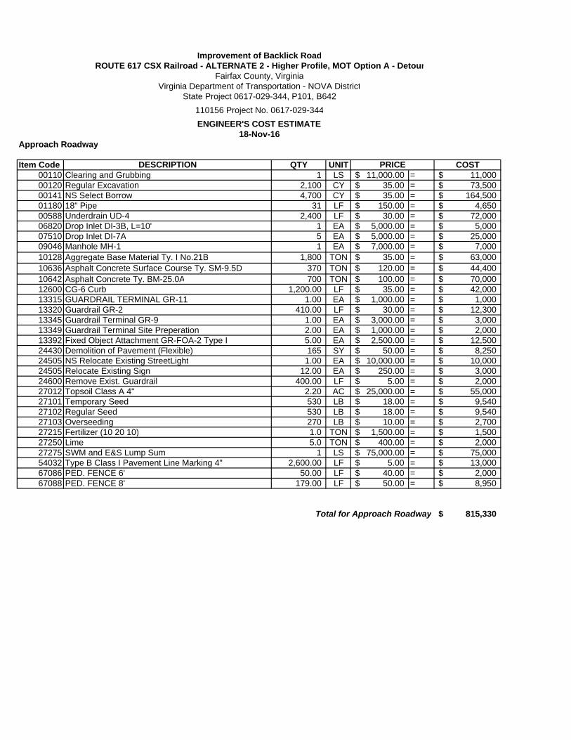
Improvement of Backlick RoadROUTE 617 CSX Railroad - ALTERNATE 2 - Higher Profile, MOT Option A - Detour
Fairfax County, VirginiaVirginia Department of Transportation - NOVA District
State Project 0617-029-344, P101, B642
110156 Project No. 0617-029-344
ENGINEER'S COST ESTIMATE18-Nov-16
Approach Roadway
Item Code QTY UNIT COST00110 Clearing and Grubbing 1 LS 11,000.00$ = 11,000$ 00120 Regular Excavation 2,100 CY 35.00$ = 73,500$ 00141 NS Select Borrow 4,700 CY 35.00$ = 164,500$ 01180 18" Pipe 31 LF 150.00$ = 4,650$ 00588 Underdrain UD-4 2,400 LF 30.00$ = 72,000$ 06820 Drop Inlet DI-3B, L=10' 1 EA 5,000.00$ = 5,000$ 07510 Drop Inlet DI-7A 5 EA 5,000.00$ = 25,000$ 09046 Manhole MH-1 1 EA 7,000.00$ = 7,000$ 10128 Aggregate Base Material Ty. I No.21B 1,800 TON 35.00$ = 63,000$ 10636 Asphalt Concrete Surface Course Ty. SM-9.5D 370 TON 120.00$ = 44,400$ 10642 Asphalt Concrete Ty. BM-25.0A 700 TON 100.00$ = 70,000$ 12600 CG-6 Curb 1,200.00 LF 35.00$ = 42,000$ 13315 GUARDRAIL TERMINAL GR‐11 1.00 EA 1,000.00$ = 1,000$ 13320 Guardrail GR-2 410.00 LF 30.00$ = 12,300$ 13345 Guardrail Terminal GR-9 1.00 EA 3,000.00$ = 3,000$ 13349 Guardrail Terminal Site Preperation 2.00 EA 1,000.00$ = 2,000$ 13392 Fixed Object Attachment GR-FOA-2 Type I 5.00 EA 2,500.00$ = 12,500$ 24430 Demolition of Pavement (Flexible) 165 SY 50.00$ = 8,250$ 24505 NS Relocate Existing StreetLight 1.00 EA 10,000.00$ = 10,000$ 24505 Relocate Existing Sign 12.00 EA 250.00$ = 3,000$ 24600 Remove Exist. Guardrail 400.00 LF 5.00$ = 2,000$ 27012 Topsoil Class A 4" 2.20 AC 25,000.00$ = 55,000$ 27101 Temporary Seed 530 LB 18.00$ = 9,540$ 27102 Regular Seed 530 LB 18.00$ = 9,540$ 27103 Overseeding 270 LB 10.00$ = 2,700$ 27215 Fertilizer (10 20 10) 1.0 TON 1,500.00$ = 1,500$ 27250 Lime 5.0 TON 400.00$ = 2,000$ 27275 SWM and E&S Lump Sum 1 LS 75,000.00$ = 75,000$ 54032 Type B Class I Pavement Line Marking 4" 2,600.00 LF 5.00$ = 13,000$ 67086 PED. FENCE 6' 50.00 LF 40.00$ = 2,000$ 67088 PED. FENCE 8' 179.00 LF 50.00$ = 8,950$
Total for Approach Roadway 815,330$
DESCRIPTION PRICE

Item Code
60409604506045260490617116181262041620436708862534
Item Code
64005640116411264765647686501365200652111381067900
Item Code
00100001016847668492
=Subtotal for Roadway & MOT =Estimate Contingency (20%) =Total =
Force Account Estimate - CSX =CEI Costs (30%) =Construction Contingency (10%) =Preliminary Engineering Cost =TOTAL COST =
Sub Total =
$679,400
$8,739,000
$3,325,600
$905,900$1,203,700
$5,435,200
$1,358,800
$800,000
$370,400
1 $284,700 $284,700Construction Surveying 1 $39,700 $39,700
LBSFLS
LSLS
Unit Unit Cost Total Item Cost
Mobilization
Reinforcing Steel 13290 $1.15 $15,290
Pile Point for 12" Steel Piles 60 $120.00 $7,200Driving Test for 12" Steel Piles 80 $90.00 $7,200
EALFCYLB
2447 $35.00 $85,650Structure Excavation 156 $50.00 $7,800
Concrete Class A3 129.4 $1,000.00 $129,400
TNCYLFSteel Piles 12" 2400 $65.00 $156,000
$94,450
Sub Total = $1,676,560
Railing, BR27C 3 Rails 179 $300.00 $53,700
Str. Steel Plate Girder ASTM A709 Grade 50W 449104 $2.30 $1,032,940$240.00 $42,960
Corrosion Resistant Reinf. Steel Cl. I 41063 $2.30LBLBLFLFLFSY
792 $10.00 $7,920$1.35 $33,350
Bridge Deck Grooving
CYCYLBSY
ALTERNATE 2B - STAGED CONSTRUCTION W/ ONE LANE OPENOne Span (135') - Steel Plate Girder with Composite Concrete Deck & MSE Walls
SUPERSTRUCTURE
Item Quantity Unit Unit Cost Total Item Cost
Conc. Class A4 Mod. Low Shrinkage 256.4 $1,000 $256,400
Total Item Cost
Select Matl. Ty. 1 Min. CBR30
ROUTE 617 OVER CSX RAILROADFairfax County, NOVA District
UPC No. 110156State Project 0617-029-344, P101, C501, B642
NS Bridge Superstructure Elastic Inclusion 14" 66 $175.00 $11,610
Railing, BR27C 1 Rail 179
Concrete Class A4 Bridge Appr. Slab 143.2 $825 $118,110Reinf. Steel Bridge Appr. Slab 24702
STAGE 1 COST ESTIMATE - STRUCTURE
Pedestrian Fence 8' 314 $80.00 $25,120
SUBSTRUCTURE
Item Quantity Unit Unit Cost
Subtotal for Bridge
$465,600
Retaining Structure (MSE Wall) 3460 $100.00 $346,000Corrosion Resistant Reinf. Steel Cl. I 6120 $2.30 $14,080
Dismantle and Remove Exst. Struct. 1 $510,000 $510,000Sub Total = $1,278,620
INCIDENTAL ITEMS
Item Quantity
Environmental and Worker Protection 1 LS $6,000 $6,000Material Disposal 1 LS $40,000 $40,000
Rte 617 over CSX ‐ Stage I Quantities ‐ Alternate 2B 11/18/2016

Improvement of Backlick RoadROUTE 617 CSX Railroad - ALTERNATE 2 - Higher Profile, MOT Option B - One Lane, Two way Traffic
Fairfax County, VirginiaVirginia Department of Transportation - NOVA District
State Project 0617-029-344, P101, B642
110156 Project No. 0617-029-344
ENGINEER'S COST ESTIMATE18-Nov-16
Approach Roadway
Item Code QTY UNIT COST00110 Clearing and Grubbing 1 LS 11,000.00$ = 11,000$ 00120 Regular Excavation 2,100 CY 35.00$ = 73,500$ 00141 NS Select Borrow 5,100 CY 35.00$ = 178,500$ 01180 18" Pipe 31 LF 150.00$ = 4,650$ 00588 Underdrain UD-4 2,400 LF 30.00$ = 72,000$ 06820 Drop Inlet DI-3B, L=10' 1 EA 5,000.00$ = 5,000$ 07510 Drop Inlet DI-7A 5 EA 5,000.00$ = 25,000$ 09046 Manhole MH-1 1 EA 7,000.00$ = 7,000$ 10128 Aggregate Base Material Ty. I No.21B 1,900 TON 35.00$ = 66,500$ 10636 Asphalt Concrete Surface Course Ty. SM-9.5D 390 TON 120.00$ = 46,800$ 10642 Asphalt Concrete Ty. BM-25.0A 700 TON 100.00$ = 70,000$ 12600 CG-6 Curb 1,200.00 LF 35.00$ = 42,000$ 13315 GUARDRAIL TERMINAL GR‐11 1.00 EA 1,000.00$ = 1,000$ 13320 Guardrail GR-2 410.00 LF 30.00$ = 12,300$ 13345 Guardrail Terminal GR-9 1.00 EA 3,000.00$ = 3,000$ 13349 Guardrail Terminal Site Preperation 2.00 EA 1,000.00$ = 2,000$ 13392 Fixed Object Attachment GR-FOA-2 Type I 5.00 EA 2,500.00$ = 12,500$ 24430 Demolition of Pavement (Flexible) 140 SY 50.00$ = 7,000$ 24505 NS Relocate Existing StreetLight 1.00 EA 10,000.00$ = 10,000$ 24505 Relocate Existing Sign 12.00 EA 250.00$ = 3,000$ 24600 Remove Exist. Guardrail 400.00 LF 5.00$ = 2,000$ 27012 Topsoil Class A 4" 2.20 AC 25,000.00$ = 55,000$ 27101 Temporary Seed 530 LB 18.00$ = 9,540$ 27102 Regular Seed 530 LB 18.00$ = 9,540$ 27103 Overseeding 270 LB 10.00$ = 2,700$ 27215 Fertilizer (10 20 10) 1.0 TON 1,500.00$ = 1,500$ 27250 Lime 5.0 TON 400.00$ = 2,000$ 27275 SWM and E&S Lump Sum 1 LS 100,000.00$ = 100,000$ 54032 Type B Class I Pavement Line Marking 4" 2,600.00 LF 5.00$ = 13,000$ 67086 PED. FENCE 6' 50.00 LF 40.00$ = 2,000$ 67088 PED. FENCE 8' 179.00 LF 50.00$ = 8,950$
Total for Approach Roadway : 858,980$
DESCRIPTION PRICE
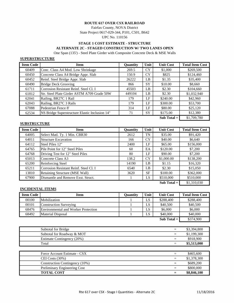
Item Code
60409604506045260490617116181262041620436708862534
Item Code
64005640116411264765647686501365200652111381067900
Item Code
00100001016847668492
=Subtotal for Roadway & MOT =Estimate Contingency (20%) =Total =
Force Account Estimate - CSX =CEI Costs (30%) =Construction Contingency (10%) =Preliminary Engineering Cost =TOTAL COST =
$689,200
$8,846,100
$3,394,800
$918,900$1,199,300
$5,513,000
$1,378,300
$800,000
Unit Unit Cost Total Item Cost
Sub Total = $374,900
Subtotal for Bridge
$465,600
Environmental and Worker Protection 1 LS $6,000 $6,000Material Disposal 1 LS $40,000
80 $90.00 $7,200
LB
Mobilization 1 $288,400 $288,400Construction Surveying 1 $40,500 $40,500
Reinforcing Steel 14190 $1.15 $16,320
LS
$362,000$15,050
$510,000$1,310,030
$91,420Structure Excavation 166 $40.00 $6,640
Concrete Class A3 138.2 $1,000.00 $138,200
TNCYLFEALFCY
Steel Piles 12" 2400 $65.00 $156,000Pile Point for 12" Steel Piles 60 $120.00 $7,200Driving Test for 12" Steel Piles
Corrosion Resistant Reinf. Steel Cl. I 45503 $2.30LBLBLFLFLFSY
Sub Total = $1,709,780
Railing, BR27C 3 Rails 179 $300.00 $53,700
Str. Steel Plate Girder ASTM A709 Grade 50W 449104 $2.30 $1,032,940$240.00 $42,960
$25,120$80.00
ALTERNATE 2C - STAGED CONSTRUCTION W/ TWO LANES OPENOne Span (135') - Steel Plate Girder with Composite Concrete Deck & MSE Walls
SUPERSTRUCTURE
Item Quantity Unit Unit Cost Total Item Cost
Conc. Class A4 Mod. Low Shrinkage 269.5 $1,000 $269,500
866 $10.00 $8,660$1.35 $35,400
Bridge Deck Grooving
CYCYLBSY
$104,660
$35.00
Total Item Cost
Select Matl. Ty. 1 Min. CBR30
ROUTE 617 OVER CSX RAILROADFairfax County, NOVA District
State Project 0617-029-344, P101, C501, B642UPC No. 110156
NS Bridge Superstructure Elastic Inclusion 14" 71 $175.00 $12,380
Railing, BR27C 1 Rail 179
Concrete Class A4 Bridge Appr. Slab 150.9 $825 $124,460Reinf. Steel Bridge Appr. Slab 26222
STAGE 1 COST ESTIMATE - STRUCTURE
Pedestrian Fence 8' 314
$40,000
SUBSTRUCTURE
Item Quantity Unit Unit Cost
LBSFLS
LS
Retaining Structure (MSE Wall) 3620 $100.00Corrosion Resistant Reinf. Steel Cl. I 6540 $2.30
Dismantle and Remove Exst. Struct. 1 $510,000Sub Total =
INCIDENTAL ITEMS
Item Quantity
2612
Rte 617 over CSX ‐ Stage I Quantities ‐ Alternate 2C 11/18/2016

Improvement of Backlick RoadROUTE 617 CSX Railroad - ALTERNATE 2 - Higher Profile, MOT Option C - Two Lane, Two way Traffic
Fairfax County, VirginiaVirginia Department of Transportation - NOVA District
State Project 0617-029-344, P101, B642
110156 Project No. 0617-029-344
ENGINEER'S COST ESTIMATE18-Nov-16
Approach Roadway
Item Code QTY UNIT COST00110 Clearing and Grubbing 1 LS 11,000.00$ = 11,000$ 00120 Regular Excavation 2,200 CY 35.00$ = 77,000$ 00141 NS Select Borrow 5,300 CY 35.00$ = 185,500$ 01180 18" Pipe 31 LF 150.00$ = 4,650$ 00588 Underdrain UD-4 2,400 LF 30.00$ = 72,000$ 06820 Drop Inlet DI-3B, L=10' 1 EA 5,000.00$ = 5,000$ 07510 Drop Inlet DI-7A 5 EA 5,000.00$ = 25,000$ 09046 Manhole MH-1 1 EA 7,000.00$ = 7,000$ 10128 Aggregate Base Material Ty. I No.21B 1,900 TON 35.00$ = 66,500$ 10636 Asphalt Concrete Surface Course Ty. SM-9.5D 400 TON 120.00$ = 48,000$ 10642 Asphalt Concrete Ty. BM-25.0A 770 TON 100.00$ = 77,000$ 12600 CG-6 Curb 1,200.00 LF 35.00$ = 42,000$ 13315 GUARDRAIL TERMINAL GR‐11 1.00 EA 1,000.00$ = 1,000$ 13320 Guardrail GR-2 410.00 LF 30.00$ = 12,300$ 13345 Guardrail Terminal GR-9 1.00 EA 3,000.00$ = 3,000$ 13349 Guardrail Terminal Site Preperation 2.00 EA 1,000.00$ = 2,000$ 13392 Fixed Object Attachment GR-FOA-2 Type I 5.00 EA 2,500.00$ = 12,500$ 24430 Demolition of Pavement (Flexible) 125 SY 50.00$ = 6,250$ 24505 NS Relocate Existing StreetLight 1.00 EA 10,000.00$ = 10,000$ 24505 Relocate Existing Sign 12.00 EA 250.00$ = 3,000$ 24600 Remove Exist. Guardrail 400.00 LF 5.00$ = 2,000$ 27012 Topsoil Class A 4" 2.20 AC 25,000.00$ = 55,000$ 27101 Temporary Seed 530 LB 18.00$ = 9,540$ 27102 Regular Seed 530 LB 18.00$ = 9,540$ 27103 Overseeding 270 LB 10.00$ = 2,700$ 27215 Fertilizer (10 20 10) 1.0 TON 1,500.00$ = 1,500$ 27250 Lime 5.0 TON 400.00$ = 2,000$ 27275 SWM and E&S Lump Sum 1 LS 100,000.00$ = 100,000$ 54032 Type B Class I Pavement Line Marking 4" 2,600.00 LF 5.00$ = 13,000$ 67086 PED. FENCE 6' 50.00 LF 40.00$ = 2,000$ 67088 PED. FENCE 8' 179.00 LF 50.00$ = 8,950$
Total for Approach Roadway : 876,930$
DESCRIPTION PRICE
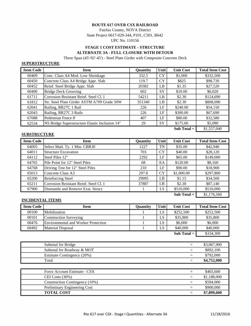
Item Code
60409604506045260490617116181262041620436708862534
Item Code
640056401164112647656476865013652006521167900
Item Code
00100001016847668492
Subtotal for Bridge =Subtotal for Roadway & MOT =Estimate Contingency (20%) =Total =
Force Account Estimate - CSX =CEI Costs (30%) =Construction Contingency (10%) =Preliminary Engineering Cost =TOTAL COST = $7,899,600
$3,067,900
$792,000$892,100
$4,752,000
$1,188,000$594,000$900,000
$465,600
Sub Total = $334,300
Mobilization 1 $252,500 $252,500Construction Surveying 1 $35,800 $35,800
LSLS
Environmental and Worker Protection 1 LS $6,000 $6,000Material Disposal 1 LS $40,000 $40,000
Dismantle and Remove Exst. Struct. 1 $510,000 $510,000Sub Total = $1,176,560
INCIDENTAL ITEMS
Item Quantity Unit Unit Cost Total Item Cost
$40.00 $28,120
Concrete Class A3 297.8 $1,000.00 $297,800Reinforcing Steel 29995 $1.15 $34,500
Pile Point for 12" Steel Piles 68 $120.00 $8,160Driving Test for 12" Steel Piles 210 $90.00 $18,900
$124,690
Sub Total = $1,557,040
Railing, BR27C 3 Rails 226 $300.00 $67,690
Str. Steel Plate Girder ASTM A709 Grade 50W 351340 $2.30 $808,090$240.00 $54,150
Corrosion Resistant Reinf. Steel Cl. I 54211 $2.30LBLBLFLFLFSY
Unit Cost Total Item Cost
Conc. Class A4 Mod. Low Shrinkage 332.5 $1,000 $332,500CY
602 $10.00 $6,020$1.35 $27,520
Bridge Deck Grooving
CYLBSY
ROUTE 617 OVER CSX RAILROADFairfax County, NOVA District
State Project 0617-029-344, P101, C501, B642UPC No. 110156
NS Bridge Superstructure Elastic Inclusion 14" 29 $175.00 $5,080
Railing, BR27C 1 Rail 226
Concrete Class A4 Bridge Appr. Slab 119.7 $825 $98,720Reinf. Steel Bridge Appr. Slab 20382
STAGE 1 COST ESTIMATE - STRUCTUREALTERNATE 3A - FULL CLOSURE WITH DETOUR
Three Span (45'-92'-45') - Steel Plate Girder with Composite Concrete DeckSUPERSTRUCTURE
Item Quantity Unit
Corrosion Resistant Reinf. Steel Cl. I 37887 $2.30 $87,140
Pedestrian Fence 8' 407 $80.00 $32,580
SUBSTRUCTURE
Item Quantity Unit Unit Cost
Steel Piles 12" 2292 $65.00 $149,000
Total Item Cost
Select Matl. Ty. 1 Min. CBR30 1227 $35.00 $42,940Structure Excavation 703
TNCYLFEALFCYLBLBLS
Rte 617 over CSX ‐ Stage I Quantities ‐ Alternate 3A 11/18/2016

Improvement of Backlick RoadROUTE 617 CSX Railroad - ALTERNATE 3 - Optimum Profile, MOT Option A - Detour
Fairfax County, VirginiaVirginia Department of Transportation - NOVA District
State Project 0617-029-344, P101, B642
110156 Project No. 0617-029-344
ENGINEER'S COST ESTIMATE18-Nov-16
Approach Roadway
Item Code QTY UNIT COST00110 Clearing and Grubbing 1 LS 11,000.00$ = 11,000$ 00120 Regular Excavation 2,200 CY 35.00$ = 77,000$ 00141 NS Select Borrow 2,300 CY 35.00$ = 80,500$ 01180 18" Pipe 31 LF 150.00$ = 4,650$ 00588 Underdrain UD-4 2,200 LF 30.00$ = 66,000$ 06820 Drop Inlet DI-3B, L=10' 1 EA 5,000.00$ = 5,000$ 07510 Drop Inlet DI-7A 5 EA 5,000.00$ = 25,000$ 09046 Manhole MH-1 1 EA 7,000.00$ = 7,000$ 10128 Aggregate Base Material Ty. I No.21B 1,600 TON 35.00$ = 56,000$ 10636 Asphalt Concrete Surface Course Ty. SM-9.5D 350 TON 120.00$ = 42,000$ 10642 Asphalt Concrete Ty. BM-25.0A 600 TON 100.00$ = 60,000$ 12600 CG-6 Curb 1,100.00 LF 35.00$ = 38,500$ 13315 GUARDRAIL TERMINAL GR‐11 1.00 EA 1,000.00$ = 1,000$ 13320 Guardrail GR-2 410.00 LF 30.00$ = 12,300$ 13345 Guardrail Terminal GR-9 1.00 EA 3,000.00$ = 3,000$ 13349 Guardrail Terminal Site Preperation 2.00 EA 1,000.00$ = 2,000$ 13392 Fixed Object Attachment GR-FOA-2 Type I 5.00 EA 2,500.00$ = 12,500$ 24430 Demolition of Pavement (Flexible) 165 SY 50.00$ = 8,250$ 24505 NS Relocate Existing StreetLight 1.00 EA 10,000.00$ = 10,000$ 24505 Relocate Existing Sign 12.00 EA 250.00$ = 3,000$ 24600 Remove Exist. Guardrail 400.00 LF 5.00$ = 2,000$ 27012 Topsoil Class A 4" 1.80 AC 25,000.00$ = 45,000$ 27101 Temporary Seed 440 LB 18.00$ = 7,920$ 27102 Regular Seed 440 LB 18.00$ = 7,920$ 27103 Overseeding 220 LB 10.00$ = 2,200$ 27215 Fertilizer (10 20 10) 1.0 TON 1,500.00$ = 1,500$ 27250 Lime 4.0 TON 400.00$ = 1,600$ 27275 SWM and E&S Lump Sum 1 LS 75,000.00$ = 75,000$ 54032 Type B Class I Pavement Line Marking 4" 2,300.00 LF 5.00$ = 11,500$ 67086 PED. FENCE 6' 50.00 LF 40.00$ = 2,000$ 67088 PED. FENCE 8' 225.00 LF 50.00$ = 11,250$
Total for Approach Roadway : 692,590$
DESCRIPTION PRICE

Item Code
60409604506045260490617116181262041620436708862534
Item Code
640056401164112647656476865013652006521167900
Item Code
00100001016847668492
Subtotal for Bridge =Subtotal for Roadway & MOT =Estimate Contingency (20%) =Total =
Force Account Estimate - CSX =CEI Costs (30%) =Construction Contingency (10%) =Preliminary Engineering Cost =TOTAL COST =
$5,613,500
$701,700
$9,084,200
$3,619,200
$935,600$1,058,700
$1,403,400
$900,000
$465,600
Sub Total = $380,200
Mobilization 1 $293,100 $293,100Construction Surveying 1 $41,100 $41,100
LSLS
Environmental and Worker Protection 1 LS $6,000 $6,000Material Disposal 1 LS $40,000 $40,000
Dismantle and Remove Exst. Struct. 1 $510,000 $510,000Sub Total = $1,340,730
INCIDENTAL ITEMS
Item Quantity Unit Unit Cost Total Item Cost
$40.00 $32,920
Concrete Class A3 371.4 $1,000.00 $371,400Reinforcing Steel 36155 $1.15 $41,580
Pile Point for 12" Steel Piles 95 $120.00 $11,400Driving Test for 12" Steel Piles 210 $90.00 $18,900
$146,560
Sub Total = $1,898,240
Railing, BR27C 3 Rails 226 $300.00 $67,690
Str. Steel Plate Girder ASTM A709 Grade 50W 452975 $2.30 $1,041,850$240.00 $54,150
Corrosion Resistant Reinf. Steel Cl. I 63721 $2.30LBLBLFLFLFSY
Unit Cost Total Item Cost
Conc. Class A4 Mod. Low Shrinkage 387.6 $1,000 $387,600
996 $10.00 $9,960$1.35 $33,350
Bridge Deck Grooving
CYCYLBSY
ROUTE 617 OVER CSX RAILROADFairfax County, NOVA District
UPC No. 110156State Project 0617-029-344, P101, C501, B642
NS Bridge Superstructure Elastic Inclusion 14" 36 $175.00 $6,390
Railing, BR27C 1 Rail 226
Concrete Class A4 Bridge Appr. Slab 143.2 $825 $118,110Reinf. Steel Bridge Appr. Slab 24702
STAGE 1 COST ESTIMATE - STRUCTUREALTERNATE 3B - STAGED CONSTRUCTION W/ ONE LANE OPENThree Span (45'-92'-45') - Steel Plate Girder with Composite Concrete Deck
SUPERSTRUCTURE
Item Quantity Unit
Corrosion Resistant Reinf. Steel Cl. I 45517 $2.30 $104,690
Pedestrian Fence 8' 407 $80.00 $32,580
SUBSTRUCTURE
Item Quantity Unit Unit Cost
Steel Piles 12" 3012 $65.00 $195,800
Total Item Cost
Select Matl. Ty. 1 Min. CBR30 1544 $35.00 $54,040Structure Excavation 823
TNCYLFEALFCYLBLBLS
Rte 617 over CSX ‐ Stage I Quantities ‐ Alternate 3B 11/18/2016

Improvement of Backlick RoadROUTE 617 CSX Railroad - ALTERNATE 3 - Optimum Profile, MOT Option B - One Lane, Two way Traffic
Fairfax County, VirginiaVirginia Department of Transportation - NOVA District
State Project 0617-029-344, P101, B642
110156 Project No. 0617-029-344
ENGINEER'S COST ESTIMATE18-Nov-16
Approach Roadway
Item Code QTY UNIT COST00110 Clearing and Grubbing 1 LS 11,000.00$ = 11,000$ 00120 Regular Excavation 2,100 CY 35.00$ = 73,500$ 00141 NS Select Borrow 2,300 CY 35.00$ = 80,500$ 01180 18" Pipe 31 LF 150.00$ = 4,650$ 00588 Underdrain UD-4 2,200 LF 30.00$ = 66,000$ 06820 Drop Inlet DI-3B, L=10' 1 EA 5,000.00$ = 5,000$ 07510 Drop Inlet DI-7A 5 EA 5,000.00$ = 25,000$ 09046 Manhole MH-1 1 EA 7,000.00$ = 7,000$ 10128 Aggregate Base Material Ty. I No.21B 1,600 TON 35.00$ = 56,000$ 10636 Asphalt Concrete Surface Course Ty. SM-9.5D 360 TON 120.00$ = 43,200$ 10642 Asphalt Concrete Ty. BM-25.0A 600 TON 100.00$ = 60,000$ 12600 CG-6 Curb 1,100.00 LF 35.00$ = 38,500$ 13315 GUARDRAIL TERMINAL GR‐11 1.00 EA 1,000.00$ = 1,000$ 13320 Guardrail GR-2 410.00 LF 30.00$ = 12,300$ 13345 Guardrail Terminal GR-9 1.00 EA 3,000.00$ = 3,000$ 13349 Guardrail Terminal Site Preperation 2.00 EA 1,000.00$ = 2,000$ 13392 Fixed Object Attachment GR-FOA-2 Type I 5.00 EA 2,500.00$ = 12,500$ 24430 Demolition of Pavement (Flexible) 140 SY 50.00$ = 7,000$ 24505 NS Relocate Existing StreetLight 1.00 EA 10,000.00$ = 10,000$ 24505 Relocate Existing Sign 12.00 EA 250.00$ = 3,000$ 24600 Remove Exist. Guardrail 400.00 LF 5.00$ = 2,000$ 27012 Topsoil Class A 4" 1.80 AC 25,000.00$ = 45,000$ 27101 Temporary Seed 440 LB 18.00$ = 7,920$ 27102 Regular Seed 440 LB 18.00$ = 7,920$ 27103 Overseeding 220 LB 10.00$ = 2,200$ 27215 Fertilizer (10 20 10) 1.0 TON 1,500.00$ = 1,500$ 27250 Lime 4.0 TON 400.00$ = 1,600$ 27275 SWM and E&S Lump Sum 1 LS 100,000.00$ = 100,000$ 54032 Type B Class I Pavement Line Marking 4" 2,300.00 LF 5.00$ = 11,500$ 67086 PED. FENCE 6' 50.00 LF 40.00$ = 2,000$ 67088 PED. FENCE 8' 225.00 LF 50.00$ = 11,250$
Total for Approach Roadway : 714,040$
DESCRIPTION PRICE

Item Code
60409604506045260490617116181262041620436708862534
Item Code
640056401164112647656476865013652006521167900
Item Code
00100001016847668492
Subtotal for Bridge =Subtotal for Roadway & MOT =Estimate Contingency (20%) =Total =
Force Account Estimate - CSX =CEI Costs (30%) =Construction Contingency (10%) =Preliminary Engineering Cost =TOTAL COST =
Environmental and Worker Protection 1 LS $6,000 $6,000Material Disposal 1 LS $40,000 $40,000
Corrosion Resistant Reinf. Steel Cl. I 46657 $2.30 $107,310
Pedestrian Fence 8' 407 $80.00 $32,580
SUBSTRUCTURE
Item Quantity Unit Unit Cost
Steel Piles 12" 3092 $65.00 $201,000
Total Item Cost
Select Matl. Ty. 1 Min. CBR30 1578 $35.00 $55,230Structure Excavation 866
ROUTE 617 OVER CSX RAILROADFairfax County, NOVA District
UPC No. 110156State Project 0617-029-344, P101, C501, B642
NS Bridge Superstructure Elastic Inclusion 14" 39 $175.00 $6,820
Railing, BR27C 1 Rail 226
Concrete Class A4 Bridge Appr. Slab 150.9 $825 $124,460Reinf. Steel Bridge Appr. Slab 26222
STAGE 1 COST ESTIMATE - STRUCTUREALTERNATE 3C - STAGED CONSTRUCTION W/ TWO LANES OPEN
Three Span (45'-92'-45') - Steel Plate Girder with Composite Concrete DeckSUPERSTRUCTURE
Item Quantity Unit Unit Cost Total Item Cost
Conc. Class A4 Mod. Low Shrinkage 405.4 $1,000 $405,400
1091 $10.00 $10,910$1.35 $35,400
Bridge Deck Grooving
CYCYLBSY
$153,920
Sub Total = $1,933,180
Railing, BR27C 3 Rails 226 $300.00 $67,690
Str. Steel Plate Girder ASTM A709 Grade 50W 452975 $2.30 $1,041,850$240.00 $54,150
Corrosion Resistant Reinf. Steel Cl. I 66921 $2.30LBLBLFLFLFSY
$40.00 $34,640
Concrete Class A3 427.2 $1,000.00 $427,200
TNCYLF
Reinforcing Steel 36575 $1.15 $42,070
Pile Point for 12" Steel Piles 97 $120.00 $11,640Driving Test for 12" Steel Piles 210 $90.00 $18,900
EALFCYLB
Mobilization 1 $299,600 $299,600Construction Surveying 1 $42,400 $42,400
Dismantle and Remove Exst. Struct. 1 $510,000 $510,000Sub Total = $1,407,990
INCIDENTAL ITEMS
Item Quantity Unit Unit Cost Total Item Cost
LBLS
LSLS
$1,063,200
$1,437,800
$900,000$9,273,200
$5,750,900
$465,600
$718,900
$3,729,200
$958,500
Sub Total = $388,000
Rte 617 over CSX ‐ Stage I Quantities ‐ Alternate 3C 11/18/2016

Improvement of Backlick RoadROUTE 617 CSX Railroad - ALTERNATE 3 - Optimum Profile, MOT Option C - Two Lane, Two Way Traffic
Fairfax County, VirginiaVirginia Department of Transportation - NOVA District
State Project 0617-029-344, P101, B642
110156 Project No. 0617-029-344
ENGINEER'S COST ESTIMATE18-Nov-16
Approach Roadway
Item Code QTY UNIT COST00110 Clearing and Grubbing 1 LS 11,000.00$ = 11,000$ 00120 Regular Excavation 2,200 CY 35.00$ = 77,000$ 00141 NS Select Borrow 2,500 CY 35.00$ = 87,500$ 01180 18" Pipe 31 LF 150.00$ = 4,650$ 00588 Underdrain UD-4 2,200 LF 30.00$ = 66,000$ 06820 Drop Inlet DI-3B, L=10' 1 EA 5,000.00$ = 5,000$ 07510 Drop Inlet DI-7A 5 EA 5,000.00$ = 25,000$ 09046 Manhole MH-1 1 EA 7,000.00$ = 7,000$ 10128 Aggregate Base Material Ty. I No.21B 1,700 TON 35.00$ = 59,500$ 10636 Asphalt Concrete Surface Course Ty. SM-9.5D 410 TON 120.00$ = 49,200$ 10642 Asphalt Concrete Ty. BM-25.0A 670 TON 100.00$ = 67,000$ 12600 CG-6 Curb 1,100.00 LF 35.00$ = 38,500$ 13315 GUARDRAIL TERMINAL GR‐11 1.00 EA 1,000.00$ = 1,000$ 13320 Guardrail GR-2 410.00 LF 30.00$ = 12,300$ 13345 Guardrail Terminal GR-9 1.00 EA 3,000.00$ = 3,000$ 13349 Guardrail Terminal Site Preperation 2.00 EA 1,000.00$ = 2,000$ 13392 Fixed Object Attachment GR-FOA-2 Type I 5.00 EA 2,500.00$ = 12,500$ 24430 Demolition of Pavement (Flexible) 135 SY 50.00$ = 6,750$ 24505 NS Relocate Existing StreetLight 1.00 EA 10,000.00$ = 10,000$ 24505 Relocate Existing Sign 12.00 EA 250.00$ = 3,000$ 24600 Remove Exist. Guardrail 400.00 LF 5.00$ = 2,000$ 27012 Topsoil Class A 4" 1.80 AC 25,000.00$ = 45,000$ 27101 Temporary Seed 440 LB 18.00$ = 7,920$ 27102 Regular Seed 440 LB 18.00$ = 7,920$ 27103 Overseeding 220 LB 10.00$ = 2,200$ 27215 Fertilizer (10 30 10) 1.0 TON 1,500.00$ = 1,500$ 27250 Lime 4.0 TON 400.00$ = 1,600$ 27275 SWM and E&S Lump Sum 1 LS 100,000.00$ = 100,000$ 54032 Type B Class I Pavement Line Marking 4" 2,300.00 LF 5.00$ = 11,500$ 67086 PED. FENCE 6' 50.00 LF 40.00$ = 2,000$ 67088 PED. FENCE 8' 225.00 LF 50.00$ = 11,250$
Total for Approach Roadway : 740,790$
DESCRIPTION PRICE

Item Code
60409604506045260490617116181262041620436708862534
Item Code
64005640116411264765647686501365200652111381067900
Item Code
00100001016847668492
=Subtotal for Roadway & MOT =Estimate Contingency (20%) =Total =
Force Account Estimate - CSX =CEI Costs (30%) =Construction Contingency (10%) =Preliminary Engineering Cost =TOTAL COST =
$800,000
$1,014,800
$8,562,400
$3,407,400
$884,500$5,306,700
$1,326,700$663,400
Subtotal for Bridge
$465,600
Sub Total = $327,300
Mobilization 1 $246,500 $246,500Construction Surveying 1 $34,800 $34,800LSEnvironmental and Worker Protection 1 LS $6,000 $6,000Material Disposal 1 LS $40,000 $40,000
$12,150
Pile Point for 12" Steel Piles 52 $120.00 $6,240Driving Test for 12" Steel Piles 80 $90.00 $7,200
LB
$68,040Structure Excavation 126 $50.00 $6,300
Concrete Class A3 102.8 $1,000.00 $102,800
TNCYLFEALFCY
Steel Piles 12" 2080 $65.00 $135,200
$78,120
Sub Total = $1,345,100
Railing, BR27C 3 Rails 179 $300.00 $53,700
Str. Steel Plate Girder ASTM A709 Grade 50W 343241 $2.30 $789,460$240.00 $42,960
Corrosion Resistant Reinf. Steel Cl. I 33963 $2.30LBLBLFLFLFSY
478 $10.00 $4,780$1.35 $27,520
Bridge Deck Grooving
CYCYLBSY
ALTERNATE 4 - FULL CLOSURE WITH DETOUR ACCELERATED BRIDGE CONSTRUCTIONOne Span (135') - Steel Plate Girder with Composite Concrete Deck & MSE Walls
SUPERSTRUCTURE
Item Quantity Unit Unit Cost Total Item Cost
Conc. Class A4 Mod. Low Shrinkage 215.5 $1,000 $215,500
Total Item Cost
Select Matl. Ty. 1 Min. CBR30
ROUTE 617 OVER CSX RAILROADFairfax County, NOVA District
State Project 0617-029-344, P101, C501, B642UPC No. 110156
NS Bridge Superstructure Elastic Inclusion 14" 53 $175.00 $9,220
Railing, BR27C 1 Rail 179
Concrete Class A4 Bridge Appr. Slab 119.7 $825 $98,720Reinf. Steel Bridge Appr. Slab 20382
STAGE 1 COST ESTIMATE - TOTAL
Pedestrian Fence 8' 314 $80.00 $25,120
SUBSTRUCTURE
Item Quantity Unit Unit Cost
LBSFLS
LS
Retaining Structure (MSE Wall) 3079 $100.00
Sub Total =
1944 $35.00
Reinforcing Steel 10560 $1.15
$1,167,030
INCIDENTAL ITEMS
Item Quantity Unit Unit Cost
$307,920Corrosion Resistant Reinf. Steel Cl. I 4860 $2.30 $11,180
Dismantle and Remove Exst. Struct. 1 $510,000 $510,000
Total Item Cost
Rte 617 over CSX ‐ Stage I Quantities ‐ Alternate 4 11/18/2016
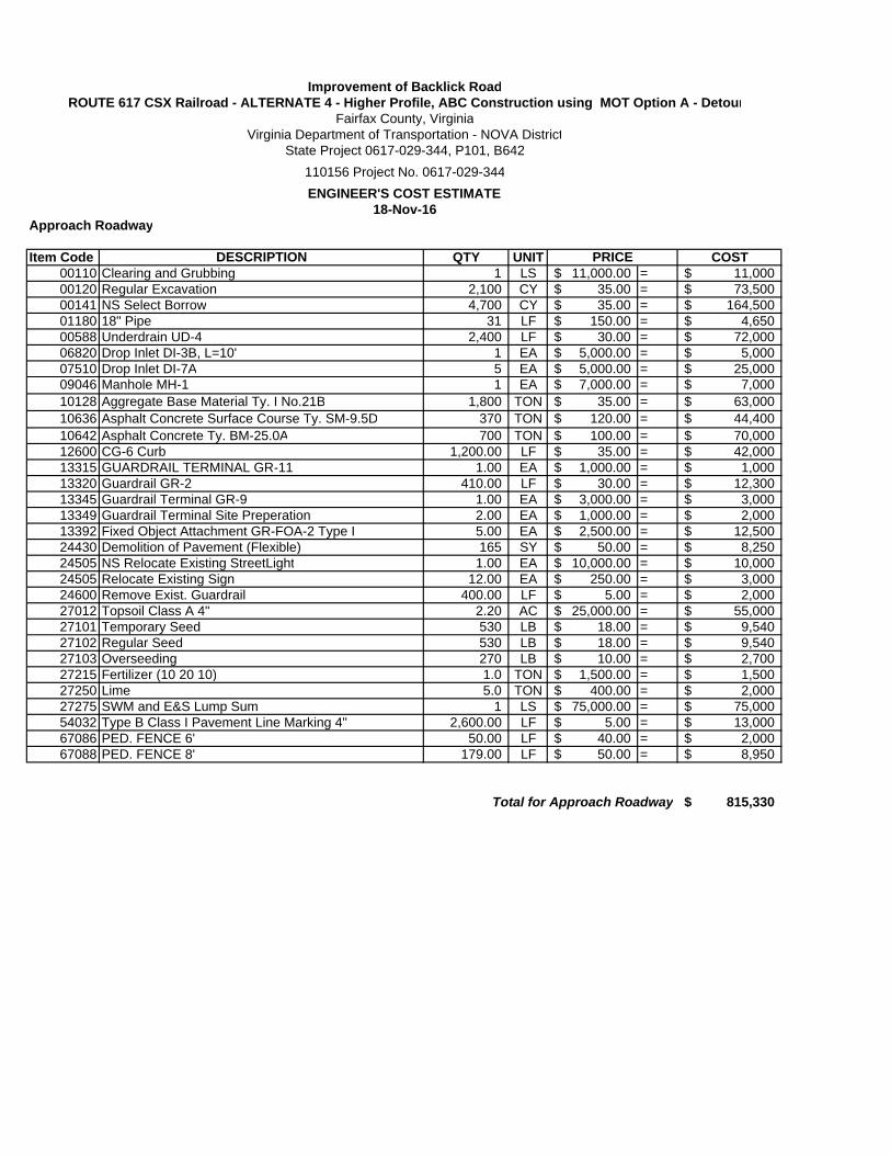
Improvement of Backlick RoadROUTE 617 CSX Railroad - ALTERNATE 4 - Higher Profile, ABC Construction using MOT Option A - Detour
Fairfax County, VirginiaVirginia Department of Transportation - NOVA District
State Project 0617-029-344, P101, B642
110156 Project No. 0617-029-344
ENGINEER'S COST ESTIMATE18-Nov-16
Approach Roadway
Item Code QTY UNIT COST00110 Clearing and Grubbing 1 LS 11,000.00$ = 11,000$ 00120 Regular Excavation 2,100 CY 35.00$ = 73,500$ 00141 NS Select Borrow 4,700 CY 35.00$ = 164,500$ 01180 18" Pipe 31 LF 150.00$ = 4,650$ 00588 Underdrain UD-4 2,400 LF 30.00$ = 72,000$ 06820 Drop Inlet DI-3B, L=10' 1 EA 5,000.00$ = 5,000$ 07510 Drop Inlet DI-7A 5 EA 5,000.00$ = 25,000$ 09046 Manhole MH-1 1 EA 7,000.00$ = 7,000$ 10128 Aggregate Base Material Ty. I No.21B 1,800 TON 35.00$ = 63,000$ 10636 Asphalt Concrete Surface Course Ty. SM-9.5D 370 TON 120.00$ = 44,400$ 10642 Asphalt Concrete Ty. BM-25.0A 700 TON 100.00$ = 70,000$ 12600 CG-6 Curb 1,200.00 LF 35.00$ = 42,000$ 13315 GUARDRAIL TERMINAL GR‐11 1.00 EA 1,000.00$ = 1,000$ 13320 Guardrail GR-2 410.00 LF 30.00$ = 12,300$ 13345 Guardrail Terminal GR-9 1.00 EA 3,000.00$ = 3,000$ 13349 Guardrail Terminal Site Preperation 2.00 EA 1,000.00$ = 2,000$ 13392 Fixed Object Attachment GR-FOA-2 Type I 5.00 EA 2,500.00$ = 12,500$ 24430 Demolition of Pavement (Flexible) 165 SY 50.00$ = 8,250$ 24505 NS Relocate Existing StreetLight 1.00 EA 10,000.00$ = 10,000$ 24505 Relocate Existing Sign 12.00 EA 250.00$ = 3,000$ 24600 Remove Exist. Guardrail 400.00 LF 5.00$ = 2,000$ 27012 Topsoil Class A 4" 2.20 AC 25,000.00$ = 55,000$ 27101 Temporary Seed 530 LB 18.00$ = 9,540$ 27102 Regular Seed 530 LB 18.00$ = 9,540$ 27103 Overseeding 270 LB 10.00$ = 2,700$ 27215 Fertilizer (10 20 10) 1.0 TON 1,500.00$ = 1,500$ 27250 Lime 5.0 TON 400.00$ = 2,000$ 27275 SWM and E&S Lump Sum 1 LS 75,000.00$ = 75,000$ 54032 Type B Class I Pavement Line Marking 4" 2,600.00 LF 5.00$ = 13,000$ 67086 PED. FENCE 6' 50.00 LF 40.00$ = 2,000$ 67088 PED. FENCE 8' 179.00 LF 50.00$ = 8,950$
Total for Approach Roadway 815,330$
DESCRIPTION PRICE
MAINTENANCE OF TRAFFIC
COST ESTIMATES

MOT OPTION A ‐ with no Bike/Pedestrian Access
ITEM CODE DESCRIPTION QTY UNIT PRICE COST
Maintenance of Traffic 270 Day
Maintenance of Traffic Lump Sum MOB 1 LS 40,000.00$ $40,000
Bike / Pedestrian Shuttle 1 LS 10,000.00$ $10,000
10128 Aggregate Base Material Ty. I No.21B 500 TON 33.00$ $16,500
10636 Asphalt Concrete Surface Course Ty. SM‐9.5D 650 TON 113.00$ $73,450
10643 Asphalt Concrete Ty. BM‐25.0D 0 TON 93.00$ $0
24160 Construction Signs 480 SF 21.50$ $10,320
24278 Group 2 Channelizing Devices 270 DAY 65.00$ $17,550
24279 PORTABLE CHANGEABLE MESSAGE SIGN 3240 HR 5.00$ $16,200
24281 ELECTRONIC ARROW 100 HR 2.25$ $225
24282 Flagger Service 50 HR 23.00$ $1,150
24297 TRAF.BARR.SER.CONC.DOUBLE FACE 300 LF 38.00$ $11,400
14260 Crusher Run Aggregate No. 25 or 26‐ 0 TON 24.00$ $0
24288 Warning Light Type B 0 DAY 2.50$ $0
50030 BARRIER DELINEATOR 50 EA 10.50$ $525
51955 Temporary Traffic Control Signal, 0 LS 30,000.00$ $0
54105 Eradication of Existing Pavement Marking 500 LF 2.25$ $1,125
54510 Construction Pavement Marking Type D Class I 500 LF 2.00$ $1,000
54514 Construction Pavement Marking Type D Class I 8" 0 LF 2.28$ $0
54522 Construction Pavement Marking Type D Class I 24" 0 LF 9.00$ $0
54240 Temporary Pavement Marker, 1‐Way 0 EA 8.25$ $0
Total for MOT = $199,445
MOT OPTION B1 ‐ One Lane with Temp Signal
ITEM CODE DESCRIPTION QTY UNIT PRICE COST
Maintenance of Traffic 270 Day
Maintenance of Traffic Lump Sum MOB 1 LS 50,000.00$ $50,000
Bike / Pedestrian Shuttle 0 LS 10,000.00$ $0
10128 Aggregate Base Material Ty. I No.21B 1000 TON 33.00$ $33,000
10636 Asphalt Concrete Surface Course Ty. SM‐9.5D 1300 TON 113.00$ $146,900
10643 Asphalt Concrete Ty. BM‐25.0D 0 TON 93.00$ $0
24160 Construction Signs 320 SF 21.50$ $6,880
24278 Group 2 Channelizing Devices 270 DAY 65.00$ $17,550
24279 PORTABLE CHANGEABLE MESSAGE SIGN 6480 HR 5.00$ $32,400
24281 ELECTRONIC ARROW 100 HR 2.25$ $225
24282 Flagger Service 200 HR 23.00$ $4,600
24297 TRAF.BARR.SER.CONC.DOUBLE FACE 420 LF 38.00$ $15,960
14260 Crusher Run Aggregate No. 25 or 26‐ 0 TON 24.00$ $0
24288 Warning Light Type B 0 DAY 2.50$ $0
50030 BARRIER DELINEATOR 70 EA 10.50$ $735
51955 Temporary Traffic Control Signal, 1 LS 30,000.00$ $30,000
54105 Eradication of Existing Pavement Marking 1500 LF 2.25$ $3,375
54510 Construction Pavement Marking Type D Class I 1500 LF 2.00$ $3,000
54514 Construction Pavement Marking Type D Class I 8" 0 LF 2.28$ $0
54522 Construction Pavement Marking Type D Class I 24" 0 LF 9.00$ $0
54240 Temporary Pavement Marker, 1‐Way 0 EA 8.25$ $0
Total for MOT = $344,625
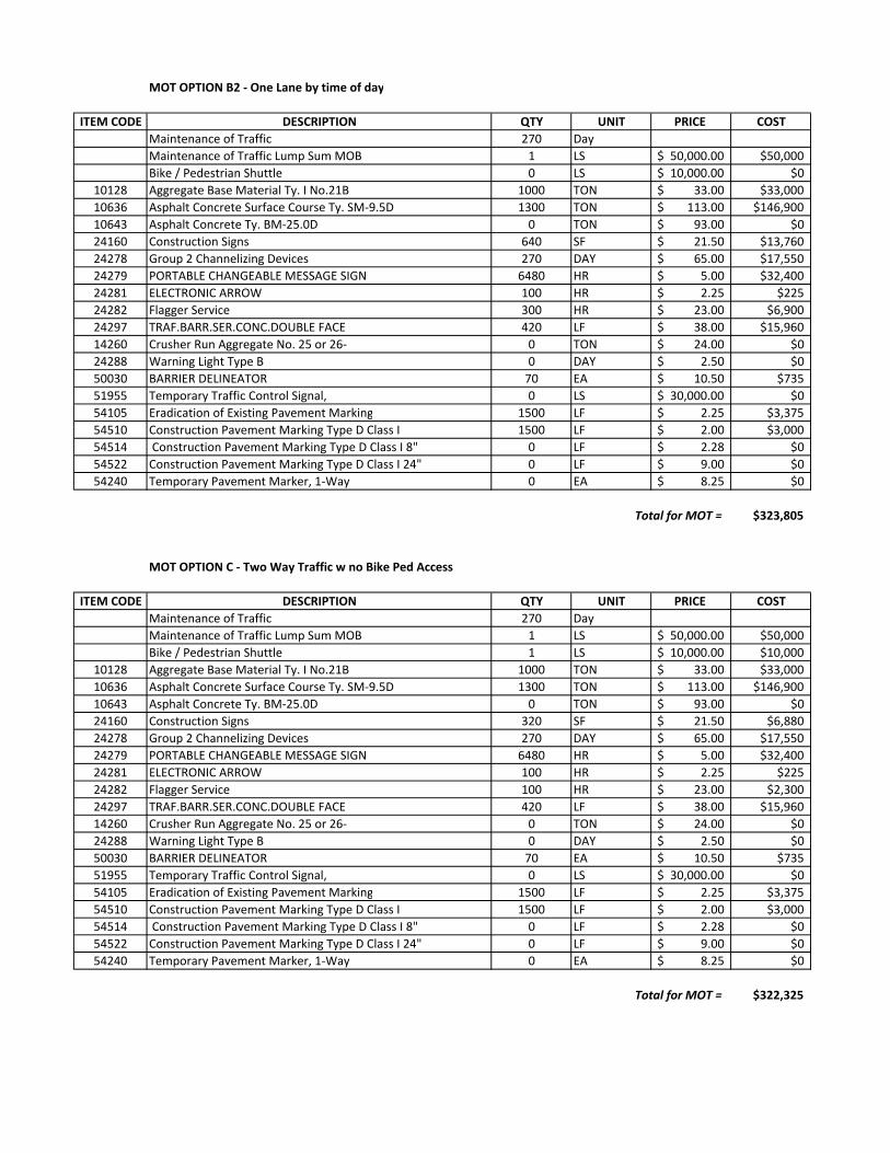
MOT OPTION B2 ‐ One Lane by time of day
ITEM CODE DESCRIPTION QTY UNIT PRICE COST
Maintenance of Traffic 270 Day
Maintenance of Traffic Lump Sum MOB 1 LS 50,000.00$ $50,000
Bike / Pedestrian Shuttle 0 LS 10,000.00$ $0
10128 Aggregate Base Material Ty. I No.21B 1000 TON 33.00$ $33,000
10636 Asphalt Concrete Surface Course Ty. SM‐9.5D 1300 TON 113.00$ $146,900
10643 Asphalt Concrete Ty. BM‐25.0D 0 TON 93.00$ $0
24160 Construction Signs 640 SF 21.50$ $13,760
24278 Group 2 Channelizing Devices 270 DAY 65.00$ $17,550
24279 PORTABLE CHANGEABLE MESSAGE SIGN 6480 HR 5.00$ $32,400
24281 ELECTRONIC ARROW 100 HR 2.25$ $225
24282 Flagger Service 300 HR 23.00$ $6,900
24297 TRAF.BARR.SER.CONC.DOUBLE FACE 420 LF 38.00$ $15,960
14260 Crusher Run Aggregate No. 25 or 26‐ 0 TON 24.00$ $0
24288 Warning Light Type B 0 DAY 2.50$ $0
50030 BARRIER DELINEATOR 70 EA 10.50$ $735
51955 Temporary Traffic Control Signal, 0 LS 30,000.00$ $0
54105 Eradication of Existing Pavement Marking 1500 LF 2.25$ $3,375
54510 Construction Pavement Marking Type D Class I 1500 LF 2.00$ $3,000
54514 Construction Pavement Marking Type D Class I 8" 0 LF 2.28$ $0
54522 Construction Pavement Marking Type D Class I 24" 0 LF 9.00$ $0
54240 Temporary Pavement Marker, 1‐Way 0 EA 8.25$ $0
Total for MOT = $323,805
MOT OPTION C ‐ Two Way Traffic w no Bike Ped Access
ITEM CODE DESCRIPTION QTY UNIT PRICE COST
Maintenance of Traffic 270 Day
Maintenance of Traffic Lump Sum MOB 1 LS 50,000.00$ $50,000
Bike / Pedestrian Shuttle 1 LS 10,000.00$ $10,000
10128 Aggregate Base Material Ty. I No.21B 1000 TON 33.00$ $33,000
10636 Asphalt Concrete Surface Course Ty. SM‐9.5D 1300 TON 113.00$ $146,900
10643 Asphalt Concrete Ty. BM‐25.0D 0 TON 93.00$ $0
24160 Construction Signs 320 SF 21.50$ $6,880
24278 Group 2 Channelizing Devices 270 DAY 65.00$ $17,550
24279 PORTABLE CHANGEABLE MESSAGE SIGN 6480 HR 5.00$ $32,400
24281 ELECTRONIC ARROW 100 HR 2.25$ $225
24282 Flagger Service 100 HR 23.00$ $2,300
24297 TRAF.BARR.SER.CONC.DOUBLE FACE 420 LF 38.00$ $15,960
14260 Crusher Run Aggregate No. 25 or 26‐ 0 TON 24.00$ $0
24288 Warning Light Type B 0 DAY 2.50$ $0
50030 BARRIER DELINEATOR 70 EA 10.50$ $735
51955 Temporary Traffic Control Signal, 0 LS 30,000.00$ $0
54105 Eradication of Existing Pavement Marking 1500 LF 2.25$ $3,375
54510 Construction Pavement Marking Type D Class I 1500 LF 2.00$ $3,000
54514 Construction Pavement Marking Type D Class I 8" 0 LF 2.28$ $0
54522 Construction Pavement Marking Type D Class I 24" 0 LF 9.00$ $0
54240 Temporary Pavement Marker, 1‐Way 0 EA 8.25$ $0
Total for MOT = $322,325
ATTACHMENT 5
STAGE I PRELIMINARY BRIDGE PLANS FOR RECOMMENDED ALTERNATE
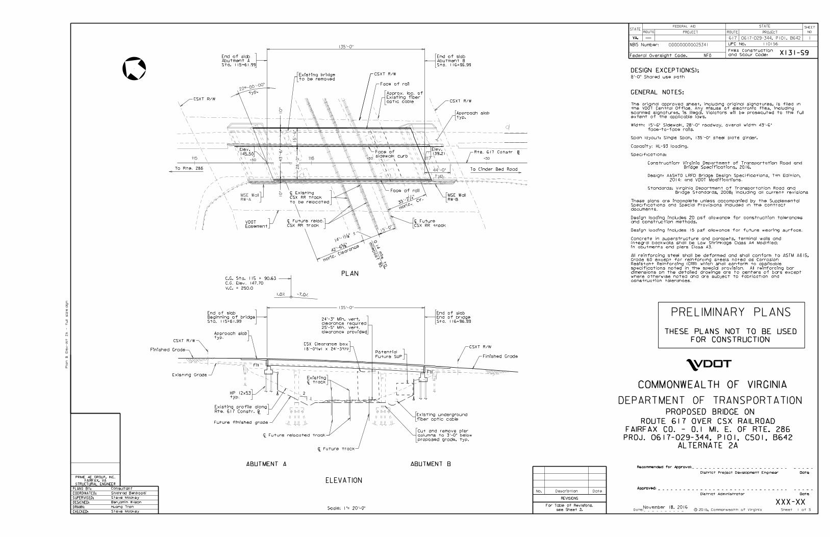
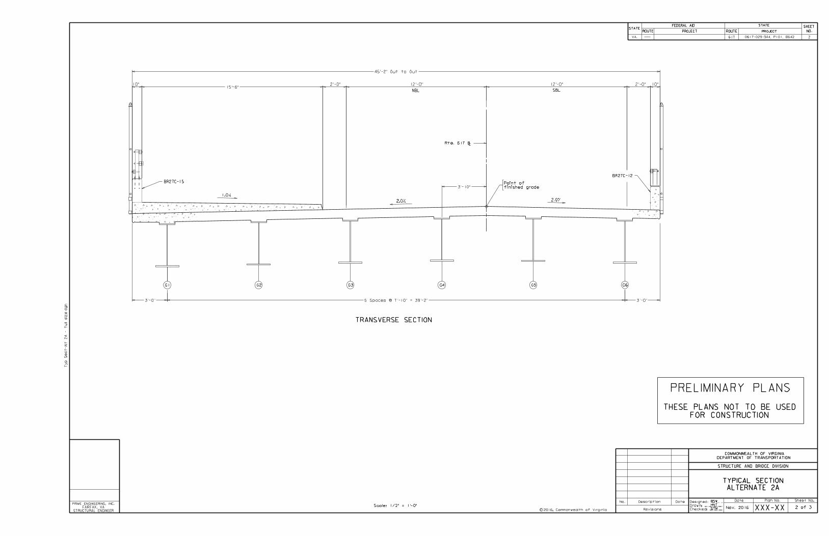
XXX-XXNov. 2016HNT
BSW
STM
617
Date Plan No. Sheet No.Designed: ...........
Drawn: ................
Checked: ............2016, Commonwealth of Virginiac
No. Description Date
STRUCTURE AND BRIDGE DIVISION
COMMONWEALTH OF VIRGINIA
DEPARTMENT OF TRANSPORTATION
Revisions
ROUTE
FEDERAL AID
PROJECT ROUTE PROJECT
STATE SHEET
NO.
VA.
STATEROUTE
FEDERAL AID
PROJECT ROUTE PROJECT
STATE SHEET
NO.STATE
Ty
p
Sect-
Alt 2
A - f
ull siz
e.d
gn
STRUCTURAL ENGINEER
FAIRFAX, VA
PRIME ENGINEERING, INC.
0617-029-344, P101, B642
TRANSVERSE SECTION
G1 G2 G3 G4 G5 G6
SBL
finished grade
Point of
NBL
Rte. 617 BL
BR27C-12
2.0% 2.0%
1.0%
BR27C-15
10"15'-6"
2'-0" 12'-0" 12'-0"
45'-2" Out to Out
10"2'-0"
3'-10"
3'-0" 5 Spaces @ 7'-10" = 39'-2"
3'-0"
ALTERNATE 2A
TYPICAL SECTION
2
2 of 3
FOR CONSTRUCTION
THESE PLANS NOT TO BE USED
PRELIMINARY PLANS
Scale: 1/2" = 1'-0"
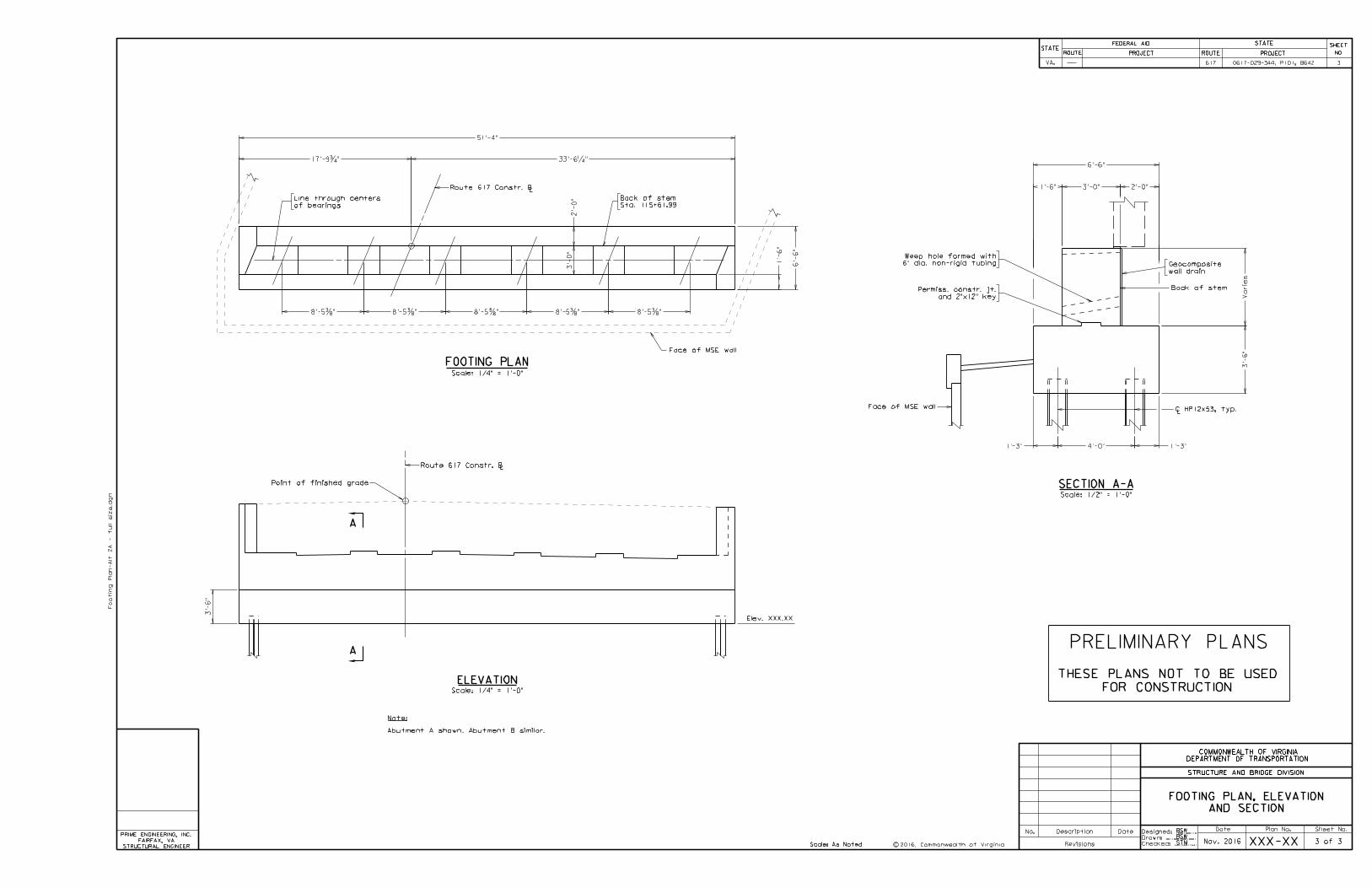
ATTACHMENT 6
TRAFFIC IMPACT STUDY - EXECUTIVE SUMMARY
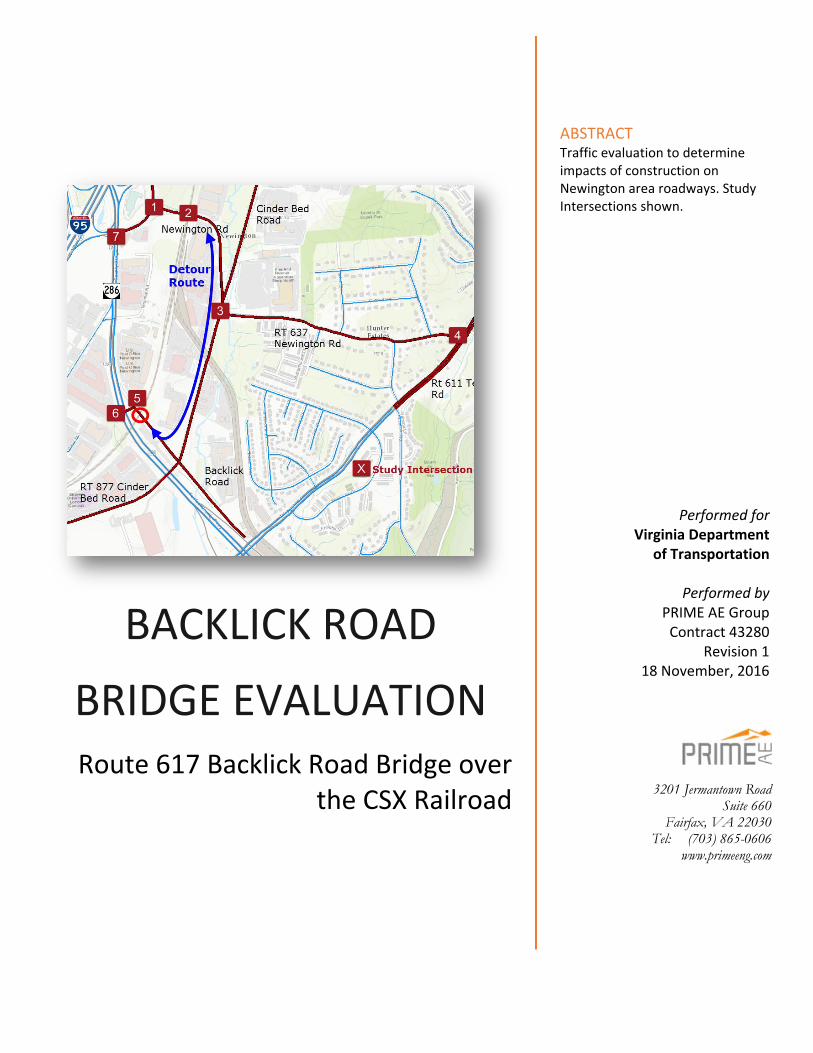
BACKLICK ROAD
BRIDGE EVALUATION Route 617 Backlick Road Bridge over
the CSX Railroad
ABSTRACT Traffic evaluation to determine impacts of construction on Newington area roadways. Study Intersections shown.
3201 Jermantown Road Suite 660
Fairfax, VA 22030 Tel: (703) 865-0606
www.primeeng.com
Performed for Virginia Department
of Transportation
Performed by PRIME AE Group Contract 43280
Revision 1 18 November, 2016

Executive Summary
ROUTE 617 BACKLICK ROAD BRIDGE REPLACEMENT Traffic Study ‐ November 2016
ROUTE 617 BACKLICK ROAD BRIDGE REPLACEMENT
Traffic Study
I Background Virginia’s Atlantic Gateway Project is a $1.4 billion series of project to address congestion on the
I‐95 corridor in Northern Virginia. The project includes 14 miles of new rail track to improve
capacity for freight, commuter and passenger rail service.
The Route 617 Bridge over the CSX railroad in the Newington Area currently has insufficient
horizontal or vertical clearance to accommodate a new rail track. A number of options to
replace the existing bridge are being investigated by PRIME AE Group in a Stage 1 Bridge Study.
This Traffic Study has the following
purposes:
1) determine the relative traffic
impacts of staged versus full
closure during construction;
2) develop traffic estimates to
inform area businesses and
residences;
3) determine mitigation that can
be performed during
construction.
The traffic impact of the proposed full
closure was evaluated for seven
intersections. Existing intersection
traffic counts were developed using
the NOVA Signal Files (Synchro files)
and updated with new 24 hour
counts. The volume of strictly external
traffic – that is “cut through” traffic – was
estimated using Bluetooth readers. Existing traffic volumes on Backlick Bridge was reassigned to
Newington Road. The seven study intersections:
1. Newington Road and Loisdale Road;
2. Newington Road Underpass of CSX Railroad;
3. Intersection of Newington Road and Cinder Bed Road;
4. Telegraph Road and Newington Road;
5. Intersection of Backlick Road and Fairfax County Parkway spur,
6. Backlick Road Spur and Fairfax County Parkway.
7. Loisdale Road and Fairfax County Parkway.

Executive Summary
ROUTE 617 BACKLICK ROAD BRIDGE REPLACEMENT Traffic Study ‐ November 2016
II Existing Traffic and Level of Service Traffic volumes on the Backlick Road bridge
over the CSX Railroad are relatively light when
compared with the surrounding road network.
The Average Daily Traffic (ADT) for Backlick
Road is 2,100 vpd. The Average Daily Traffic
(ADT) for Fairfax County Parkway is 40,000
vpd.
The figure to the right shows peak hour
vehicles per hour. These peak hour volumes are
based on VDOT Synchro files and recent September 2016 24 hour tube counts. Peak hour
volumes less than 200 are considered light.
The intersection that is most likely to have be affected by a full closure is Intersection 2 –
Newington Road Underpass. This intersection is not a true intersection, rather it is a one‐way
segment of roadway. Small platoons of three or four vehicles take turns going through the
underpass. This results in a low capacity segment of roadway. This operation was simulated with
a single phase signal with a short maximum green split.
Queues from the Newington Road
CSX Underpass vary as shown in
the table on the following page.
The distance between the
Underpass and Loisdale Road is
approximately 450 feet. The
queues shown are the result of
traffic simulation using
SIMTRAFFIC, and are similar to
queues observed in the field.
The highest volume in the Study
Area is Intersection 7 ‐ Loisdale
Road and Fairfax County Parkway.
The LOS observed at this
intersection is worse than LOS
calculated by Synchro. Loisdale
Road and Fairfax County Parkway
is LOS F in the AM, and this is due
to a very heavy eastbound
movement.
Intersection Level of Service
AM Peak
PM Peak
MD1 Period
Off‐Peak
1. Newington Road and Loisdale Road
B 15.4
C 30.9
B 16.5
C 30.3
2. Newington Road Underpass of CSX Railroad (E/W)
F/F 122/ 118
C/F 32.0/ 335
D/D 44.8/ 45.6
D/F 51.0/ 154
3. Newington Road and Cinder Bed Road
‐ ‐ ‐ ‐
4. Telegraph Road and Newington Road
B 17.6
C 34.2
B 16.0
B 11.6
5. Backlick Road and Fairfax County Parkway Spur
A 9.5
B 10.2
B 12.2
A 9.0
6. Backlick Road Spur and Fairfax County Parkway
B 19.9
B 15.5
B 12.0
A 8.2
7. Loisdale Road and Fairfax County Parkway
F 96.5
D 35.7
D 37.5
B 17.6
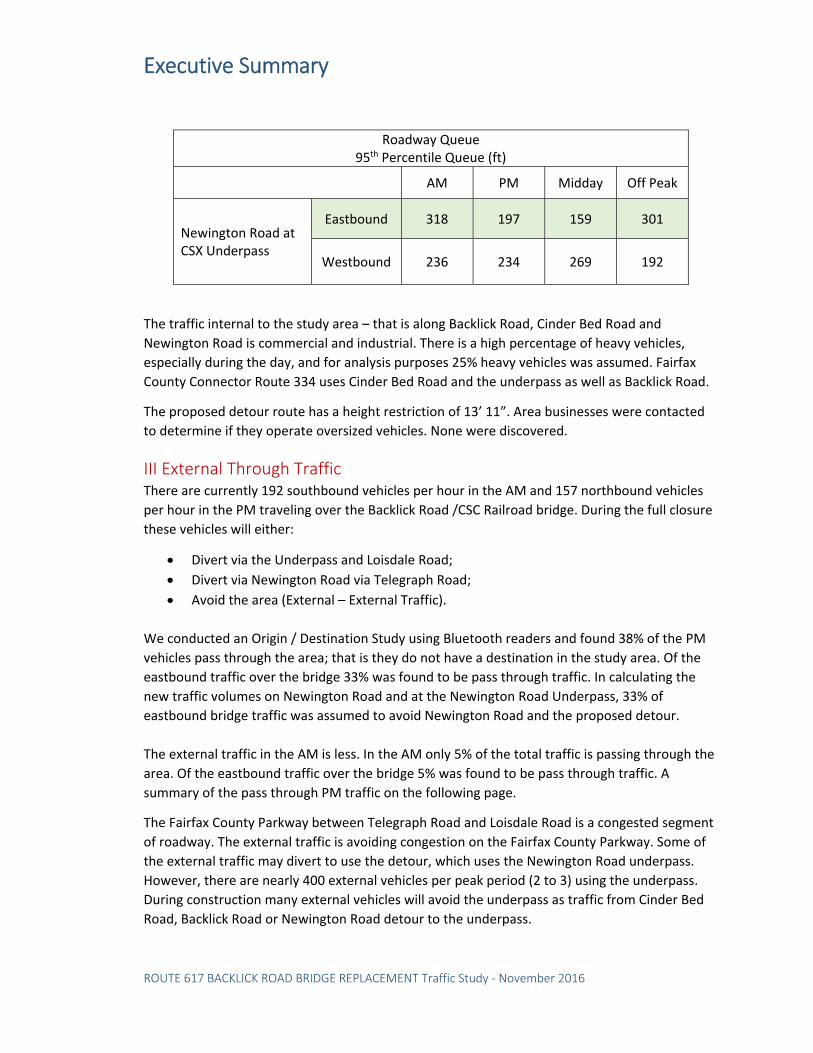
Executive Summary
ROUTE 617 BACKLICK ROAD BRIDGE REPLACEMENT Traffic Study ‐ November 2016
The traffic internal to the study area – that is along Backlick Road, Cinder Bed Road and
Newington Road is commercial and industrial. There is a high percentage of heavy vehicles,
especially during the day, and for analysis purposes 25% heavy vehicles was assumed. Fairfax
County Connector Route 334 uses Cinder Bed Road and the underpass as well as Backlick Road.
The proposed detour route has a height restriction of 13’ 11”. Area businesses were contacted
to determine if they operate oversized vehicles. None were discovered.
III External Through Traffic There are currently 192 southbound vehicles per hour in the AM and 157 northbound vehicles
per hour in the PM traveling over the Backlick Road /CSC Railroad bridge. During the full closure
these vehicles will either:
Divert via the Underpass and Loisdale Road;
Divert via Newington Road via Telegraph Road;
Avoid the area (External – External Traffic).
We conducted an Origin / Destination Study using Bluetooth readers and found 38% of the PM
vehicles pass through the area; that is they do not have a destination in the study area. Of the
eastbound traffic over the bridge 33% was found to be pass through traffic. In calculating the
new traffic volumes on Newington Road and at the Newington Road Underpass, 33% of
eastbound bridge traffic was assumed to avoid Newington Road and the proposed detour.
The external traffic in the AM is less. In the AM only 5% of the total traffic is passing through the
area. Of the eastbound traffic over the bridge 5% was found to be pass through traffic. A
summary of the pass through PM traffic on the following page.
The Fairfax County Parkway between Telegraph Road and Loisdale Road is a congested segment
of roadway. The external traffic is avoiding congestion on the Fairfax County Parkway. Some of
the external traffic may divert to use the detour, which uses the Newington Road underpass.
However, there are nearly 400 external vehicles per peak period (2 to 3) using the underpass.
During construction many external vehicles will avoid the underpass as traffic from Cinder Bed
Road, Backlick Road or Newington Road detour to the underpass.
Roadway Queue 95th Percentile Queue (ft)
AM PM Midday Off Peak
Newington Road at CSX Underpass
Eastbound 318 197 159 301
Westbound 236 234 269 192

Executive Summary
ROUTE 617 BACKLICK ROAD BRIDGE REPLACEMENT Traffic Study ‐ November 2016
Injury 35,712 35.70% 13 35.10%
K 232 0.20% 0 0.00%
PDO 64,134 64.10% 24 64.90%
Total 100,078 37
NOVA District Study Area
Table ES – 4: Crash Comparison – NOVA District vs Study
Area, Years: 2013 ‐ 2016
The table below shows the share of traffic that is External / External during the AM and PM peak
periods.
Crash History The study intersections and the Newington area roadways have light traffic and few crashes
over the past 3 1/2 years. The higher volume intersections at Loisdale Road and Telegraph Road
had eight and seven crashes respectively. Neither have been identified as high Potential Safety
Improvement (PSI) intersections by VDOT Traffic Engineering Division. Overall the study
intersections and Newington area roadways had 37 crashes over the 3 1/2‐year period. The
share of Injury vs Property Damage Only (PDO) crashes is consistent with NOVA District for the
same period:
Table ES – 3: PM Peak Period (3 hour) Origin‐Destination Table
Destinations
PM 1 2 3 4 Total EXTERNAL
Origins
1 35 70 210 316 33.4%
2 39 399 1,041 1,479 29.6%
3 46 381 293 720 59.4%
4 283 423 329 1,035
Total 368 839 799 1,544 EXTERNAL 23.2% 49.6% 58.8% 37.7% 1. Backlick Bridge
2. Newington Road vic Telegraph Road 3. Newington Underpass 4. Internal to study area
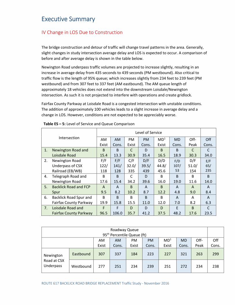
Executive Summary
ROUTE 617 BACKLICK ROAD BRIDGE REPLACEMENT Traffic Study ‐ November 2016
IV Change in LOS Due to Construction
The bridge construction and detour of traffic will change travel patterns in the area. Generally,
slight changes in study intersection average delay and LOS is expected to occur. A comparison of
before and after average delay is shown in the table below.
Newington Road underpass traffic volumes are projected to increase slightly, resulting in an
increase in average delay from 435 seconds to 439 seconds (PM westbound). Also critical to
traffic flow is the length of 95% queue; which increases slightly from 234 feet to 239 feet (PM
westbound) and from 307 feet to 337 feet (AM eastbound). The AM queue length of
approximately 18 vehicles does not extend into the downstream Loisdale/Newington
intersection. As such it is not projected to interfere with operations and create gridlock.
Fairfax County Parkway at Loisdale Road is a congested intersection with unstable conditions.
The addition of approximately 100 vehicles leads to a slight increase in average delay and a
change in LOS. However, conditions are not expected to be appreciably worse.
Table ES – 5: Level of Service and Queue Comparison
Intersection Level of Service
AM Exist
AM Cons.
PM Exist
PM Cons.
MD1 Exist
MD Cons.
Off‐Peak
Off Cons.
1. Newington Road and Loisdale Road
B 15.4
B 13.3
C 30.9
D 35.4
B 16.5
B 18.9
C 30.3
C 34.0
2. Newington Road Underpass of CSX Railroad (EB/WB)
F/F 122/ 118
F/F 141/128
C/F 32.0/335
D/F 39.5/ 439
D/D 44.8/ 45.6
F/D 107/ 53
D/F 51.0/ 154
E/F 65/ 235
4. Telegraph Road and Newington Road
B 17.6
B 15.4
C 34.2
D 39.6
B 16.0
B 19.0
B 11.6
B 14.0
5. Backlick Road and FCP Spur
A 9.5
A 8.2
B 10.2
A 8.7
B 12.2
A 4.8
A 9.0
A 8.4
6. Backlick Road Spur and Fairfax County Parkway
B 19.9
B 15.8
B 15.5
B 11.0
B 12.0
A 7.0
A 8.2
A 6.3
7. Loisdale Road and Fairfax County Parkway
F 96.5
F 106.0
D 35.7
D 41.2
D 37.5
E 48.2
B 17.6
C 23.5
Roadway Queue 95th Percentile Queue (ft)
AM Exist
AM Cons.
PM Exist
PM Cons.
MD1 Exist
MD Cons.
Off‐Peak
Off Cons.
Newington Road at CSX Underpass
Eastbound 307 337 184 223 227 321 263 299
Westbound 277 251 234 239 251 272 234 238
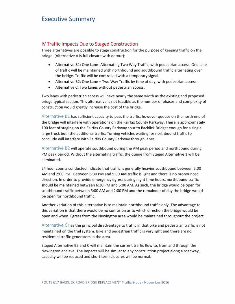
Executive Summary
ROUTE 617 BACKLICK ROAD BRIDGE REPLACEMENT Traffic Study ‐ November 2016
IV Traffic Impacts Due to Staged Construction Three alternatives are possible to stage construction for the purpose of keeping traffic on the
bridge. (Alternative A is full closure with detour):
Alternative B1: One Lane ‐Alternating Two Way Traffic, with pedestrian access. One lane
of traffic will be maintained with northbound and southbound traffic alternating over
the bridge. Traffic will be controlled with a temporary signal.
Alternative B2: One Lane – Two Way Traffic by time of day, with pedestrian access.
Alternative C: Two Lanes without pedestrian access.
Two lanes with pedestrian access will have nearly the same width as the existing and proposed
bridge typical section. This alternative is not feasible as the number of phases and complexity of
construction would greatly increase the cost of the bridge.
Alternative B1 has sufficient capacity to pass the traffic, however queues on the north end of the bridge will interfere with operations on the Fairfax County Parkway. There is approximately
100 feet of staging on the Fairfax County Parkway spur to Backlick Bridge; enough for a single
large truck but little additional traffic. Turning vehicles waiting for northbound traffic to
conclude will interfere with Fairfax County Parkway through lanes.
Alternative B2 will operate southbound during the AM peak period and northbound during
PM peak period. Without the alternating traffic, the queue from Staged Alternative 1 will be
eliminated.
24 hour counts conducted indicate that traffic is generally heavier southbound between 5:00
AM and 2:00 PM. Between 6:30 PM and 5:00 AM traffic is light and there is no pronounced
direction. In order to provide emergency egress during night time hours, northbound traffic
should be maintained between 6:30 PM and 5:00 AM. As such, the bridge would be open for
southbound traffic between 5:00 AM and 2:00 PM and the remainder of day the bridge would
be open for northbound traffic.
Another variation of this alternative is to maintain northbound traffic only. The advantage to
this variation is that there would be no confusion as to which direction the bridge would be
open and when. Egress from the Newington area would be maintained throughout the project.
Alternative C has the principal disadvantage to traffic in that bike and pedestrian traffic is not maintained on the trail system. Bike and pedestrian traffic is very light and there are no
residential traffic generators in the area.
Staged Alternative B2 and C will maintain the current traffic flow to, from and through the
Newington enclave. The impacts will be similar to any construction project along a roadway,
capacity will be reduced and short term closures will be normal.
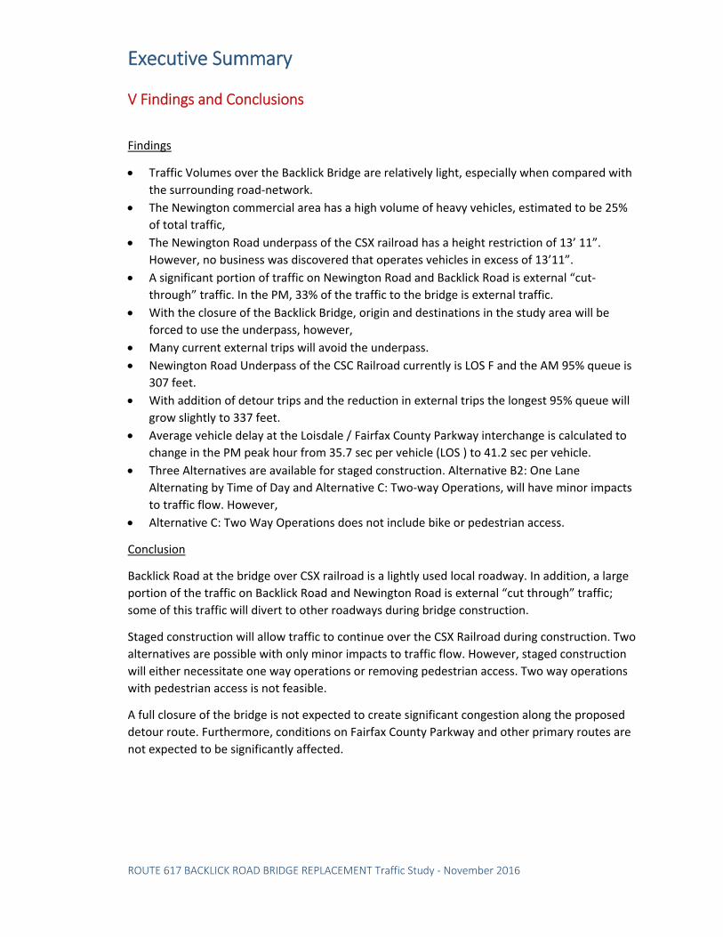
Executive Summary
ROUTE 617 BACKLICK ROAD BRIDGE REPLACEMENT Traffic Study ‐ November 2016
V Findings and Conclusions
Findings
Traffic Volumes over the Backlick Bridge are relatively light, especially when compared with
the surrounding road‐network.
The Newington commercial area has a high volume of heavy vehicles, estimated to be 25%
of total traffic,
The Newington Road underpass of the CSX railroad has a height restriction of 13’ 11”.
However, no business was discovered that operates vehicles in excess of 13’11”.
A significant portion of traffic on Newington Road and Backlick Road is external “cut‐
through” traffic. In the PM, 33% of the traffic to the bridge is external traffic.
With the closure of the Backlick Bridge, origin and destinations in the study area will be
forced to use the underpass, however,
Many current external trips will avoid the underpass.
Newington Road Underpass of the CSC Railroad currently is LOS F and the AM 95% queue is
307 feet.
With addition of detour trips and the reduction in external trips the longest 95% queue will
grow slightly to 337 feet.
Average vehicle delay at the Loisdale / Fairfax County Parkway interchange is calculated to
change in the PM peak hour from 35.7 sec per vehicle (LOS ) to 41.2 sec per vehicle.
Three Alternatives are available for staged construction. Alternative B2: One Lane
Alternating by Time of Day and Alternative C: Two‐way Operations, will have minor impacts
to traffic flow. However,
Alternative C: Two Way Operations does not include bike or pedestrian access.
Conclusion
Backlick Road at the bridge over CSX railroad is a lightly used local roadway. In addition, a large
portion of the traffic on Backlick Road and Newington Road is external “cut through” traffic;
some of this traffic will divert to other roadways during bridge construction.
Staged construction will allow traffic to continue over the CSX Railroad during construction. Two
alternatives are possible with only minor impacts to traffic flow. However, staged construction
will either necessitate one way operations or removing pedestrian access. Two way operations
with pedestrian access is not feasible.
A full closure of the bridge is not expected to create significant congestion along the proposed
detour route. Furthermore, conditions on Fairfax County Parkway and other primary routes are
not expected to be significantly affected.

ATTACHMENT 7
ABC CONSTRUCTION TIME ESTIMATE OF ALTERNATE 4
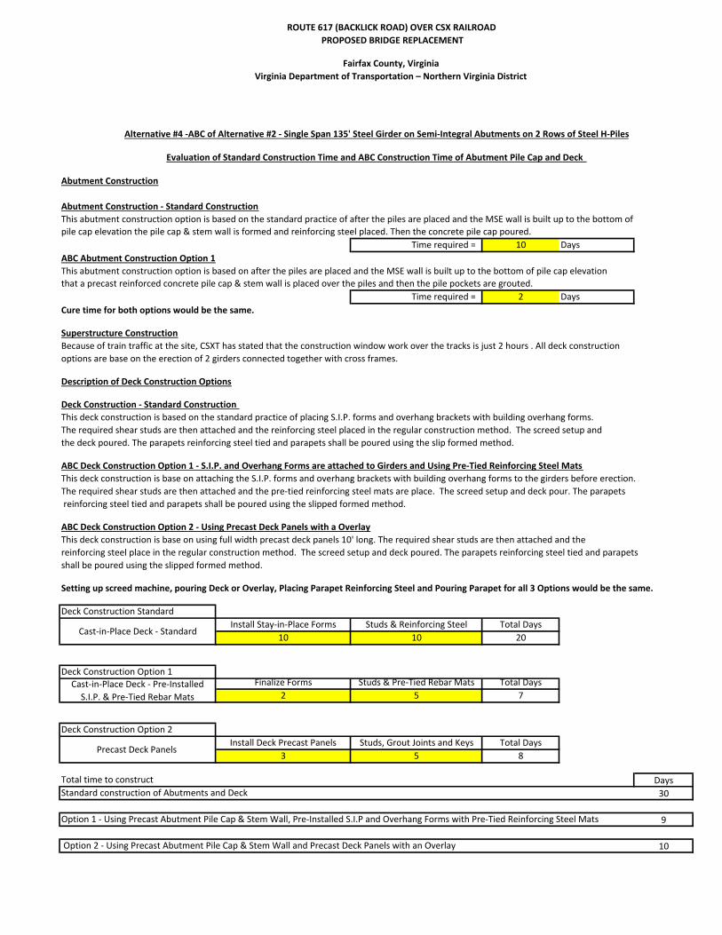
ROUTE 617 (BACKLICK ROAD) OVER CSX RAILROAD
PROPOSED BRIDGE REPLACEMENT
Fairfax County, Virginia
Virginia Department of Transportation – Northern Virginia District
Abutment Construction
Abutment Construction ‐ Standard Construction
This abutment construction option is based on the standard practice of after the piles are placed and the MSE wall is built up to the bottom of
pile cap elevation the pile cap & stem wall is formed and reinforcing steel placed. Then the concrete pile cap poured.
Time required = 10 Days
ABC Abutment Construction Option 1
This abutment construction option is based on after the piles are placed and the MSE wall is built up to the bottom of pile cap elevation
that a precast reinforced concrete pile cap & stem wall is placed over the piles and then the pile pockets are grouted.
Time required = 2 Days
Cure time for both options would be the same.
Superstructure Construction
Because of train traffic at the site, CSXT has stated that the construction window work over the tracks is just 2 hours . All deck construction
options are base on the erection of 2 girders connected together with cross frames.
Description of Deck Construction Options
Deck Construction ‐ Standard Construction
This deck construction is based on the standard practice of placing S.I.P. forms and overhang brackets with building overhang forms.
The required shear studs are then attached and the reinforcing steel placed in the regular construction method. The screed setup and
the deck poured. The parapets reinforcing steel tied and parapets shall be poured using the slip formed method.
ABC Deck Construction Option 1 ‐ S.I.P. and Overhang Forms are attached to Girders and Using Pre‐Tied Reinforcing Steel Mats
This deck construction is base on attaching the S.I.P. forms and overhang brackets with building overhang forms to the girders before erection.
The required shear studs are then attached and the pre‐tied reinforcing steel mats are place. The screed setup and deck pour. The parapets
reinforcing steel tied and parapets shall be poured using the slipped formed method.
ABC Deck Construction Option 2 ‐ Using Precast Deck Panels with a Overlay
This deck construction is base on using full width precast deck panels 10' long. The required shear studs are then attached and the
reinforcing steel place in the regular construction method. The screed setup and deck poured. The parapets reinforcing steel tied and parapets
shall be poured using the slipped formed method.
Setting up screed machine, pouring Deck or Overlay, Placing Parapet Reinforcing Steel and Pouring Parapet for all 3 Options would be the same.
Deck Construction Standard
Install Stay‐in‐Place Forms Studs & Reinforcing Steel Total Days
10 10 20
Deck Construction Option 1Finalize Forms Studs & Pre‐Tied Rebar Mats Total Days
2 5 7
Deck Construction Option 2
Install Deck Precast Panels Studs, Grout Joints and Keys Total Days
3 5 8
Total time to construct Days
Standard construction of Abutments and Deck 30
9
Option 2 ‐ Using Precast Abutment Pile Cap & Stem Wall and Precast Deck Panels with an Overlay 10
Alternative #4 ‐ABC of Alternative #2 ‐ Single Span 135' Steel Girder on Semi‐Integral Abutments on 2 Rows of Steel H‐Piles
Cast‐in‐Place Deck ‐ Pre‐Installed
S.I.P. & Pre‐Tied Rebar Mats
Cast‐in‐Place Deck ‐ Standard
Precast Deck Panels
Option 1 ‐ Using Precast Abutment Pile Cap & Stem Wall, Pre‐Installed S.I.P and Overhang Forms with Pre‐Tied Reinforcing Steel Mats
Evaluation of Standard Construction Time and ABC Construction Time of Abutment Pile Cap and Deck

ATTACHMENT 8
STORMWATER COMPUTATIONS

Design
AlternateMOT Option
Total Land
Disturbance
Qualified for
Nutrient Credits
Nutrient Credits
Required
(Phophorous
Reduction
(Lb/Year)
Remarks
1 Detour 1.90 Yes 0.49
2 Detour 1.96 Yes 0.50
One‐Lane / Two‐
Way2.07 Yes 0.60
Two‐Lane / Two‐
Way2.08 Yes 0.65
3 Detour 1.74 Yes 0.48
One‐Lane / Two‐
Way1.72 Yes 0.60
Two‐Lane / Two‐
Way1.73 Yes 0.65
4 Detour 1.96 Yes 0.50
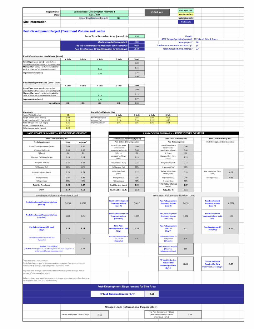
Project Name: Date:
Linear Development Project? No
Site Information
Post-Development Project (Treatment Volume and Loads)1.90 ####
20% Linear project? NoThe site's net increase in impervious cover (acres) is: 0.03 ✔
Post-Development TP Load Reduction for Site (lb/yr): 0.49 ✔
Pre-ReDevelopment Land Cover (acres)A Soils B Soils C Soils D Soils Totals
Forest/Open Space (acres) -- undisturbed, protected forest/open space or reforested land
0.00
Managed Turf (acres) -- disturbed, graded for yards or other turf to be mowed/managed 1.16 1.16
Impervious Cover (acres) 0.74 0.74
1.90
Post-Development Land Cover (acres)A Soils B Soils C Soils D Soils Totals
Forest/Open Space (acres) -- undisturbed, protected forest/open space or reforested land
0.00
Managed Turf (acres) -- disturbed, graded for yards or other turf to be mowed/managed 1.13 1.13
Impervious Cover (acres) 0.77 0.77
Area Check OK. OK. OK. OK. 1.90
Constants Runoff Coefficients (Rv)Annual Rainfall (inches) 43 A Soils B Soils C Soils D SoilsTarget Rainfall Event (inches) 1.00 Forest/Open Space 0.02 0.03 0.04 0.05Total Phosphorus (TP) EMC (mg/L) 0.26 Managed Turf 0.15 0.20 0.22 0.25Total Nitrogen (TN) EMC (mg/L) 1.86 Impervious Cover 0.95 0.95 0.95 0.95Target TP Load (lb/acre/yr) 0.41Pj (unitless correction factor) 0.90
Pre-ReDevelopment Listed Adjusted1
Forest/Open Space Cover (acres) 0.00 0.00 Forest/Open Space Cover (acres)
0.00 Forest/Open Space Cover (acres)
0.00
Weighted Rv(forest) 0.00 0.00 Weighted Rv(forest) 0.00 Weighted Rv(forest) 0.00% Forest 0% 0% % Forest 0% % Forest 0%
Managed Turf Cover (acres) 1.16 1.13 Managed Turf Cover (acres)
1.13 Managed Turf Cover (acres)
1.13
Weighted Rv(turf) 0.22 0.22 Weighted Rv (turf) 0.22 Weighted Rv (turf) 0.22
% Managed Turf 61% 60% % Managed Turf 59% % Managed Turf 60%
Impervious Cover (acres) 0.74 0.74 Impervious Cover (acres)
0.77 ReDev. Impervious Cover (acres)
0.74 New Impervious Cover (acres)
0.03
Rv(impervious) 0.95 0.95 Rv(impervious) 0.95 Rv(impervious) 0.95 Rv(impervious) 0.95
% Impervious 39% 40% % Impervious 41% % Impervious 40%
Total Site Area (acres) 1.90 1.87 Final Site Area (acres) 1.90 Total ReDev. Site Area (acres)
1.87
Site Rv 0.50 0.51 Final Post Dev Site Rv 0.52 ReDev Site Rv 0.51
Pre-ReDevelopment Treatment Volume (acre-ft)
0.0799 0.0793Final Post-Development
Treatment Volume (acre-ft)
0.0817Post-ReDevelopment
Treatment Volume (acre-ft)
0.0793Post-Development Treatment Volume
(acre-ft) 0.0024
Pre-ReDevelopment Treatment Volume (cubic feet)
3,478 3,454Final Post-Development
Treatment Volume (cubic feet)
3,558Post-ReDevelopment
Treatment Volume (cubic feet)
3,454Post-Development
Treatment Volume (cubic feet)
103
Pre-ReDevelopment TP Load (lb/yr) 2.19 2.17
Final Post-Development TP Load
(lb/yr)2.24
Post-ReDevelopment Load (TP) (lb/yr)*
2.17Post-Development TP
Load (lb/yr) 0.07
Pre-ReDevelopment TP Load per acre(lb/acre/yr)
1.15 1.16Final Post-Development TP
Load per acre (lb/acre/yr)
1.18Post-ReDevelopment TP
Load per acre (lb/acre/yr)
1.16
0.77Max. Reduction Required
(Below Pre-ReDevelopment Load)
20%
TP Load Reduction Required for
Redeveloped Area (lb/yr)
0.43TP Load Reduction Required for New
Impervious Area (lb/yr)0.05
0.49
N/A
15.63
Backlick Road -Detour Option Alternate 110/11/2016
LAND COVER SUMMARY -- POST DEVELOPMENTLAND COVER SUMMARY -- PRE-REDEVELOPMENT
Maximum reduction required:
Enter Total Disturbed Area (acres) → Check:
Land cover areas entered correctly?Total disturbed area entered?
BMP Design Specifications List:
Linear Project TP Load Reduction Required (lb/yr):
Treatment Volume and Nutrient Load
Land Cover Summary-Post (Final)
2013 Draft Stds & Specs
Land Cover Summary-Pre
Pre-ReDevelopment TN Load (lb/yr)Final Post-Development TN Load
(Post-ReDevelopment & New Impervious) (lb/yr)
15.99
Land Cover Summary-Post
Post-ReDevelopment
TP Load Reduction Required (lb/yr)
Post-Development Requirement for Site Area
Nitrogen Loads (Informational Purposes Only)
Baseline TP Load (lb/yr)(0.41 lbs/acre/yr applied to pre-redevelopment area excluding pervious
land proposed for new impervious cover)
1 Adjusted Land Cover Summary: Pre ReDevelopment land cover minus pervious land cover (forest/open space or managed turf) acreage proposed for new impervious cover.
Adjusted total acreage is consistent with Post-ReDevelopment acreage (minus acreage of new impervious cover).
Column I shows load reduction requriement for new impervious cover (based on new development load limit, 0.41 lbs/acre/year).
Post ReDev. & New Impervious
Treatment Volume and Nutrient Load
Land Cover Summary-Post
Post-Development New Impervious
CLEAR ALL data input cells
constant values
calculation cells
final results

Project Name:
Date:
Linear Development Project? No
Site Information
Post‐Development Project (Treatment Volume and Loads)
1.96 ####
20% Linear project? No
The site's net increase in impervious cover (acres) is: 0.03 ✔Post‐Development TP Load Reduction for Site (lb/yr): 0.50 ✔
Pre‐ReDevelopment Land Cover (acres)A Soils B Soils C Soils D Soils Totals
Forest/Open Space (acres) ‐‐ undisturbed,
protected forest/open space or reforested land0.00
Managed Turf (acres) ‐‐ disturbed, graded for
yards or other turf to be mowed/managed 1.201.20
Impervious Cover (acres)0.76
0.76
1.96
Post‐Development Land Cover (acres)A Soils B Soils C Soils D Soils Totals
Forest/Open Space (acres) ‐‐ undisturbed,
protected forest/open space or reforested land0.00
Managed Turf (acres) ‐‐ disturbed, graded for
yards or other turf to be mowed/managed 1.171.17
Impervious Cover (acres)0.79
0.79
Area Check OK. OK. OK. OK. 1.96
Constants Runoff Coefficients (Rv)Annual Rainfall (inches) 43 A Soils B Soils C Soils D Soils
Target Rainfall Event (inches) 1.00 Forest/Open Space 0.02 0.03 0.04 0.05
Total Phosphorus (TP) EMC (mg/L) 0.26 Managed Turf 0.15 0.20 0.22 0.25
Total Nitrogen (TN) EMC (mg/L) 1.86 Impervious Cover 0.95 0.95 0.95 0.95
Target TP Load (lb/acre/yr) 0.41
Pj (unitless correction factor) 0.90
Pre‐ReDevelopment Listed Adjusted1
Forest/Open Space Cover (acres) 0.00 0.00Forest/Open Space
Cover (acres)0.00
Forest/Open Space
Cover (acres)0.00
Weighted Rv(forest) 0.00 0.00 Weighted Rv(forest) 0.00 Weighted Rv(forest) 0.00
% Forest 0% 0% % Forest 0% % Forest 0%
Managed Turf Cover (acres) 1.20 1.17Managed Turf Cover
(acres)1.17
Managed Turf Cover
(acres)1.17
Weighted Rv(turf) 0.22 0.22 Weighted Rv (turf) 0.22 Weighted Rv (turf) 0.22
% Managed Turf 61% 61% % Managed Turf 60% % Managed Turf 61%
Impervious Cover (acres) 0.76 0.76Impervious Cover
(acres)0.79
ReDev. Impervious
Cover (acres)0.76
New Impervious Cover
(acres)0.03
Rv(impervious) 0.95 0.95 Rv(impervious) 0.95 Rv(impervious) 0.95 Rv(impervious) 0.95
% Impervious 39% 39% % Impervious 40% % Impervious 39%
Total Site Area (acres) 1.96 1.93 Final Site Area (acres) 1.96Total ReDev. Site Area
(acres)1.93
Site Rv 0.50 0.51 Final Post Dev Site Rv 0.51 ReDev Site Rv 0.51
Pre‐ReDevelopment Treatment Volume
(acre‐ft) 0.0822 0.0816
Final Post‐
Development
Treatment Volume
(acre‐ft)
0.0840Post‐ReDevelopment
Treatment Volume
(acre‐ft)
0.0816Post‐Development
Treatment Volume
(acre‐ft)
0.0024
Pre‐ReDevelopment Treatment Volume
(cubic feet) 3,579 3,555
Final Post‐
Development
Treatment Volume
(cubic feet)
3,659Post‐ReDevelopment
Treatment Volume
(cubic feet)
3,555Post‐Development
Treatment Volume (cubic
feet)
103
Pre‐ReDevelopment TP Load
(lb/yr)2.25 2.23
Final Post‐
Development TP
Load
(lb/yr)
2.30Post‐ReDevelopment
Load (TP)
(lb/yr)*
2.23Post‐Development TP
Load (lb/yr)0.07
Pre‐ReDevelopment TP Load per acre
(lb/acre/yr)1.15 1.16
Final Post‐Development TP
Load per acre
(lb/acre/yr)
1.17
Post‐ReDevelopment TP
Load per acre
(lb/acre/yr)
1.16
0.79Max. Reduction Required
(Below Pre‐
ReDevelopment Load)
20%
TP Load Reduction
Required for
Redeveloped Area
(lb/yr)
0.45TP Load Reduction
Required for New
Impervious Area (lb/yr)0.05
0.50
N/A
16.09Pre‐ReDevelopment TN Load (lb/yr)
Final Post‐Development TN Load
(Post‐ReDevelopment & New
Impervious) (lb/yr)
16.44
Land Cover Summary‐Post
Post‐ReDevelopment
TP Load Reduction Required (lb/yr)
Post‐Development Requirement for Site Area
Nitrogen Loads (Informational Purposes Only)
Baseline TP Load (lb/yr)(0.41 lbs/acre/yr applied to pre‐redevelopment area excluding pervious
land proposed for new impervious cover)
1 Adjusted Land Cover Summary:
Pre ReDevelopment land cover minus pervious land cover (forest/open space or
managed turf) acreage proposed for new impervious cover.
Adjusted total acreage is consistent with Post‐ReDevelopment acreage (minus
acreage of new impervious cover).
Column I shows load reduction requriement for new impervious cover (based on new
development load limit, 0.41 lbs/acre/year).
Post ReDev. & New Impervious
Treatment Volume and Nutrient Load
Land Cover Summary‐Post
Post‐Development New Impervious
Linear Project TP Load Reduction Required (lb/yr):
Treatment Volume and Nutrient Load
Land Cover Summary‐Post (Final)
2013 Draft Stds & Specs
Land Cover Summary‐Pre
Backlick Road ‐Detour Option Alternate 2
10/11/2016
LAND COVER SUMMARY -- POST DEVELOPMENTLAND COVER SUMMARY -- PRE-REDEVELOPMENT
Maximum reduction required:
Enter Total Disturbed Area (acres) → Check:
Land cover areas entered correctly?
Total disturbed area entered?
BMP Design Specifications List:
CLEAR ALL(Ctrl+Shift+R)
data input cells
constant values
calculation cells
final results

Project Name:
Date:
Linear Development Project? No
Site Information
Post‐Development Project (Treatment Volume and Loads)
2.07 ####
20% Linear project? No
The site's net increase in impervious cover (acres) is: 0.09 ✔Post‐Development TP Load Reduction for Site (lb/yr): 0.60 ✔
Pre‐ReDevelopment Land Cover (acres)A Soils B Soils C Soils D Soils Totals
Forest/Open Space (acres) ‐‐ undisturbed,
protected forest/open space or reforested land0.00
Managed Turf (acres) ‐‐ disturbed, graded for
yards or other turf to be mowed/managed 1.331.33
Impervious Cover (acres)0.74
0.74
2.07
Post‐Development Land Cover (acres)A Soils B Soils C Soils D Soils Totals
Forest/Open Space (acres) ‐‐ undisturbed,
protected forest/open space or reforested land0.00
Managed Turf (acres) ‐‐ disturbed, graded for
yards or other turf to be mowed/managed 1.241.24
Impervious Cover (acres)0.83
0.83
Area Check OK. OK. OK. OK. 2.07
Constants Runoff Coefficients (Rv)Annual Rainfall (inches) 43 A Soils B Soils C Soils D Soils
Target Rainfall Event (inches) 1.00 Forest/Open Space 0.02 0.03 0.04 0.05
Total Phosphorus (TP) EMC (mg/L) 0.26 Managed Turf 0.15 0.20 0.22 0.25
Total Nitrogen (TN) EMC (mg/L) 1.86 Impervious Cover 0.95 0.95 0.95 0.95
Target TP Load (lb/acre/yr) 0.41
Pj (unitless correction factor) 0.90
Pre‐ReDevelopment Listed Adjusted1
Forest/Open Space Cover (acres) 0.00 0.00Forest/Open Space
Cover (acres)0.00
Forest/Open Space
Cover (acres)0.00
Weighted Rv(forest) 0.00 0.00 Weighted Rv(forest) 0.00 Weighted Rv(forest) 0.00
% Forest 0% 0% % Forest 0% % Forest 0%
Managed Turf Cover (acres) 1.33 1.24Managed Turf Cover
(acres)1.24
Managed Turf Cover
(acres)1.24
Weighted Rv(turf) 0.22 0.22 Weighted Rv (turf) 0.22 Weighted Rv (turf) 0.22
% Managed Turf 64% 63% % Managed Turf 60% % Managed Turf 63%
Impervious Cover (acres) 0.74 0.74Impervious Cover
(acres)0.83
ReDev. Impervious
Cover (acres)0.74
New Impervious Cover
(acres)0.09
Rv(impervious) 0.95 0.95 Rv(impervious) 0.95 Rv(impervious) 0.95 Rv(impervious) 0.95
% Impervious 36% 37% % Impervious 40% % Impervious 37%
Total Site Area (acres) 2.07 1.98 Final Site Area (acres) 2.07Total ReDev. Site Area
(acres)1.98
Site Rv 0.48 0.49 Final Post Dev Site Rv 0.51 ReDev Site Rv 0.49
Pre‐ReDevelopment Treatment Volume
(acre‐ft) 0.0830 0.0813
Final Post‐
Development
Treatment Volume
(acre‐ft)
0.0884Post‐ReDevelopment
Treatment Volume
(acre‐ft)
0.0813Post‐Development
Treatment Volume
(acre‐ft)
0.0071
Pre‐ReDevelopment Treatment Volume
(cubic feet) 3,614 3,542
Final Post‐
Development
Treatment Volume
(cubic feet)
3,853Post‐ReDevelopment
Treatment Volume
(cubic feet)
3,542Post‐Development
Treatment Volume (cubic
feet)
310
Pre‐ReDevelopment TP Load
(lb/yr)2.27 2.23
Final Post‐
Development TP
Load
(lb/yr)
2.42Post‐ReDevelopment
Load (TP)
(lb/yr)*
2.23Post‐Development TP
Load (lb/yr)0.20
Pre‐ReDevelopment TP Load per acre
(lb/acre/yr)1.10 1.12
Final Post‐Development TP
Load per acre
(lb/acre/yr)
1.17
Post‐ReDevelopment TP
Load per acre
(lb/acre/yr)
1.12
0.81Max. Reduction Required
(Below Pre‐
ReDevelopment Load)
20%
TP Load Reduction
Required for
Redeveloped Area
(lb/yr)
0.45TP Load Reduction
Required for New
Impervious Area (lb/yr)0.16
0.60
N/A
16.24Pre‐ReDevelopment TN Load (lb/yr)
Final Post‐Development TN Load
(Post‐ReDevelopment & New
Impervious) (lb/yr)
17.32
Land Cover Summary‐Post
Post‐ReDevelopment
TP Load Reduction Required (lb/yr)
Post‐Development Requirement for Site Area
Nitrogen Loads (Informational Purposes Only)
Baseline TP Load (lb/yr)(0.41 lbs/acre/yr applied to pre‐redevelopment area excluding pervious
land proposed for new impervious cover)
1 Adjusted Land Cover Summary:
Pre ReDevelopment land cover minus pervious land cover (forest/open space or
managed turf) acreage proposed for new impervious cover.
Adjusted total acreage is consistent with Post‐ReDevelopment acreage (minus
acreage of new impervious cover).
Column I shows load reduction requriement for new impervious cover (based on new
development load limit, 0.41 lbs/acre/year).
Post ReDev. & New Impervious
Treatment Volume and Nutrient Load
Land Cover Summary‐Post
Post‐Development New Impervious
Linear Project TP Load Reduction Required (lb/yr):
Treatment Volume and Nutrient Load
Land Cover Summary‐Post (Final)
2013 Draft Stds & Specs
Land Cover Summary‐Pre
Backlick Road ‐One Lane Option Alternate 2
10/11/2016
LAND COVER SUMMARY -- POST DEVELOPMENTLAND COVER SUMMARY -- PRE-REDEVELOPMENT
Maximum reduction required:
Enter Total Disturbed Area (acres) → Check:
Land cover areas entered correctly?
Total disturbed area entered?
BMP Design Specifications List:
CLEAR ALL(Ctrl+Shift+R)
data input cells
constant values
calculation cells
final results

Project Name:
Date:
Linear Development Project? No
Site Information
Post‐Development Project (Treatment Volume and Loads)
2.08 ####
20% Linear project? No
The site's net increase in impervious cover (acres) is: 0.11 ✔Post‐Development TP Load Reduction for Site (lb/yr): 0.65 ✔
Pre‐ReDevelopment Land Cover (acres)A Soils B Soils C Soils D Soils Totals
Forest/Open Space (acres) ‐‐ undisturbed,
protected forest/open space or reforested land0.00
Managed Turf (acres) ‐‐ disturbed, graded for
yards or other turf to be mowed/managed 1.301.30
Impervious Cover (acres)0.78
0.78
2.08
Post‐Development Land Cover (acres)A Soils B Soils C Soils D Soils Totals
Forest/Open Space (acres) ‐‐ undisturbed,
protected forest/open space or reforested land0.00
Managed Turf (acres) ‐‐ disturbed, graded for
yards or other turf to be mowed/managed 1.191.19
Impervious Cover (acres)0.89
0.89
Area Check OK. OK. OK. OK. 2.08
Constants Runoff Coefficients (Rv)Annual Rainfall (inches) 43 A Soils B Soils C Soils D Soils
Target Rainfall Event (inches) 1.00 Forest/Open Space 0.02 0.03 0.04 0.05
Total Phosphorus (TP) EMC (mg/L) 0.26 Managed Turf 0.15 0.20 0.22 0.25
Total Nitrogen (TN) EMC (mg/L) 1.86 Impervious Cover 0.95 0.95 0.95 0.95
Target TP Load (lb/acre/yr) 0.41
Pj (unitless correction factor) 0.90
Pre‐ReDevelopment Listed Adjusted1
Forest/Open Space Cover (acres) 0.00 0.00Forest/Open Space
Cover (acres)0.00
Forest/Open Space
Cover (acres)0.00
Weighted Rv(forest) 0.00 0.00 Weighted Rv(forest) 0.00 Weighted Rv(forest) 0.00
% Forest 0% 0% % Forest 0% % Forest 0%
Managed Turf Cover (acres) 1.30 1.19Managed Turf Cover
(acres)1.19
Managed Turf Cover
(acres)1.19
Weighted Rv(turf) 0.22 0.22 Weighted Rv (turf) 0.22 Weighted Rv (turf) 0.22
% Managed Turf 63% 60% % Managed Turf 57% % Managed Turf 60%
Impervious Cover (acres) 0.78 0.78Impervious Cover
(acres)0.89
ReDev. Impervious
Cover (acres)0.78
New Impervious Cover
(acres)0.11
Rv(impervious) 0.95 0.95 Rv(impervious) 0.95 Rv(impervious) 0.95 Rv(impervious) 0.95
% Impervious 38% 40% % Impervious 43% % Impervious 40%
Total Site Area (acres) 2.08 1.97 Final Site Area (acres) 2.08Total ReDev. Site Area
(acres)1.97
Site Rv 0.49 0.51 Final Post Dev Site Rv 0.53 ReDev Site Rv 0.51
Pre‐ReDevelopment Treatment Volume
(acre‐ft) 0.0856 0.0836
Final Post‐
Development
Treatment Volume
(acre‐ft)
0.0923Post‐ReDevelopment
Treatment Volume
(acre‐ft)
0.0836Post‐Development
Treatment Volume
(acre‐ft)
0.0087
Pre‐ReDevelopment Treatment Volume
(cubic feet) 3,728 3,640
Final Post‐
Development
Treatment Volume
(cubic feet)
4,019Post‐ReDevelopment
Treatment Volume
(cubic feet)
3,640Post‐Development
Treatment Volume (cubic
feet)
379
Pre‐ReDevelopment TP Load
(lb/yr)2.34 2.29
Final Post‐
Development TP
Load
(lb/yr)
2.53Post‐ReDevelopment
Load (TP)
(lb/yr)*
2.29Post‐Development TP
Load (lb/yr)0.24
Pre‐ReDevelopment TP Load per acre
(lb/acre/yr)1.13 1.16
Final Post‐Development TP
Load per acre
(lb/acre/yr)
1.21
Post‐ReDevelopment TP
Load per acre
(lb/acre/yr)
1.16
0.81Max. Reduction Required
(Below Pre‐
ReDevelopment Load)
20%
TP Load Reduction
Required for
Redeveloped Area
(lb/yr)
0.46TP Load Reduction
Required for New
Impervious Area (lb/yr)0.19
0.65
N/A
16.76
Backlick Road ‐Two Lane Option Alt 2
10/11/2016
LAND COVER SUMMARY -- POST DEVELOPMENTLAND COVER SUMMARY -- PRE-REDEVELOPMENT
Maximum reduction required:
Enter Total Disturbed Area (acres) → Check:
Land cover areas entered correctly?
Total disturbed area entered?
BMP Design Specifications List:
Linear Project TP Load Reduction Required (lb/yr):
Treatment Volume and Nutrient Load
Land Cover Summary‐Post (Final)
2013 Draft Stds & Specs
Land Cover Summary‐Pre
Pre‐ReDevelopment TN Load (lb/yr)
Final Post‐Development TN Load
(Post‐ReDevelopment & New
Impervious) (lb/yr)
18.07
Land Cover Summary‐Post
Post‐ReDevelopment
TP Load Reduction Required (lb/yr)
Post‐Development Requirement for Site Area
Nitrogen Loads (Informational Purposes Only)
Baseline TP Load (lb/yr)(0.41 lbs/acre/yr applied to pre‐redevelopment area excluding pervious
land proposed for new impervious cover)
1 Adjusted Land Cover Summary:
Pre ReDevelopment land cover minus pervious land cover (forest/open space or
managed turf) acreage proposed for new impervious cover.
Adjusted total acreage is consistent with Post‐ReDevelopment acreage (minus
acreage of new impervious cover).
Column I shows load reduction requriement for new impervious cover (based on new
development load limit, 0.41 lbs/acre/year).
Post ReDev. & New Impervious
Treatment Volume and Nutrient Load
Land Cover Summary‐Post
Post‐Development New Impervious
CLEAR ALL(Ctrl+Shift+R)
data input cells
constant values
calculation cells
final results
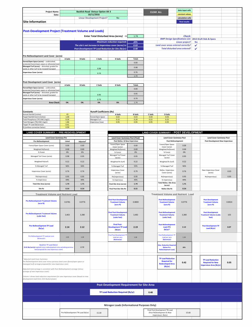
Project Name: Date:
Linear Development Project? No
Site Information
Post-Development Project (Treatment Volume and Loads)1.74 ####
20% Linear project? NoThe site's net increase in impervious cover (acres) is: 0.03 ✔
Post-Development TP Load Reduction for Site (lb/yr): 0.48 ✔
Pre-ReDevelopment Land Cover (acres)A Soils B Soils C Soils D Soils Totals
Forest/Open Space (acres) -- undisturbed, protected forest/open space or reforested land
0.00
Managed Turf (acres) -- disturbed, graded for yards or other turf to be mowed/managed 0.98 0.98
Impervious Cover (acres) 0.76 0.76
1.74
Post-Development Land Cover (acres)A Soils B Soils C Soils D Soils Totals
Forest/Open Space (acres) -- undisturbed, protected forest/open space or reforested land
0.00
Managed Turf (acres) -- disturbed, graded for yards or other turf to be mowed/managed 0.95 0.95
Impervious Cover (acres) 0.79 0.79
Area Check OK. OK. OK. OK. 1.74
Constants Runoff Coefficients (Rv)Annual Rainfall (inches) 43 A Soils B Soils C Soils D SoilsTarget Rainfall Event (inches) 1.00 Forest/Open Space 0.02 0.03 0.04 0.05Total Phosphorus (TP) EMC (mg/L) 0.26 Managed Turf 0.15 0.20 0.22 0.25Total Nitrogen (TN) EMC (mg/L) 1.86 Impervious Cover 0.95 0.95 0.95 0.95Target TP Load (lb/acre/yr) 0.41Pj (unitless correction factor) 0.90
Pre-ReDevelopment Listed Adjusted1
Forest/Open Space Cover (acres) 0.00 0.00 Forest/Open Space Cover (acres)
0.00 Forest/Open Space Cover (acres)
0.00
Weighted Rv(forest) 0.00 0.00 Weighted Rv(forest) 0.00 Weighted Rv(forest) 0.00% Forest 0% 0% % Forest 0% % Forest 0%
Managed Turf Cover (acres) 0.98 0.95 Managed Turf Cover (acres)
0.95 Managed Turf Cover (acres)
0.95
Weighted Rv(turf) 0.22 0.22 Weighted Rv (turf) 0.22 Weighted Rv (turf) 0.22
% Managed Turf 56% 56% % Managed Turf 55% % Managed Turf 56%
Impervious Cover (acres) 0.76 0.76 Impervious Cover (acres)
0.79 ReDev. Impervious Cover (acres)
0.76 New Impervious Cover (acres)
0.03
Rv(impervious) 0.95 0.95 Rv(impervious) 0.95 Rv(impervious) 0.95 Rv(impervious) 0.95
% Impervious 44% 44% % Impervious 45% % Impervious 44%
Total Site Area (acres) 1.74 1.71 Final Site Area (acres) 1.74 Total ReDev. Site Area (acres)
1.71
Site Rv 0.54 0.54 Final Post Dev Site Rv 0.55 ReDev Site Rv 0.54
Pre-ReDevelopment Treatment Volume (acre-ft)
0.0781 0.0776Final Post-Development
Treatment Volume (acre-ft)
0.0800Post-ReDevelopment
Treatment Volume (acre-ft)
0.0776Post-Development Treatment Volume
(acre-ft) 0.0024
Pre-ReDevelopment Treatment Volume (cubic feet)
3,403 3,380Final Post-Development
Treatment Volume (cubic feet)
3,483Post-ReDevelopment
Treatment Volume (cubic feet)
3,380Post-Development
Treatment Volume (cubic feet)
103
Pre-ReDevelopment TP Load (lb/yr) 2.14 2.12
Final Post-Development TP Load
(lb/yr)2.19
Post-ReDevelopment Load (TP) (lb/yr)*
2.12Post-Development TP
Load (lb/yr) 0.07
Pre-ReDevelopment TP Load per acre(lb/acre/yr)
1.23 1.24Final Post-Development TP
Load per acre (lb/acre/yr)
1.26Post-ReDevelopment TP
Load per acre (lb/acre/yr)
1.24
0.70Max. Reduction Required
(Below Pre-ReDevelopment Load)
20%
TP Load Reduction Required for
Redeveloped Area (lb/yr)
0.42TP Load Reduction Required for New
Impervious Area (lb/yr)0.05
0.48
N/A
15.30
Backlick Road -Detour Option Alt 310/11/2016
LAND COVER SUMMARY -- POST DEVELOPMENTLAND COVER SUMMARY -- PRE-REDEVELOPMENT
Maximum reduction required:
Enter Total Disturbed Area (acres) → Check:
Land cover areas entered correctly?Total disturbed area entered?
BMP Design Specifications List:
Linear Project TP Load Reduction Required (lb/yr):
Treatment Volume and Nutrient Load
Land Cover Summary-Post (Final)
2013 Draft Stds & Specs
Land Cover Summary-Pre
Pre-ReDevelopment TN Load (lb/yr)Final Post-Development TN Load
(Post-ReDevelopment & New Impervious) (lb/yr)
15.66
Land Cover Summary-Post
Post-ReDevelopment
TP Load Reduction Required (lb/yr)
Post-Development Requirement for Site Area
Nitrogen Loads (Informational Purposes Only)
Baseline TP Load (lb/yr)(0.41 lbs/acre/yr applied to pre-redevelopment area excluding pervious
land proposed for new impervious cover)
1 Adjusted Land Cover Summary: Pre ReDevelopment land cover minus pervious land cover (forest/open space or managed turf) acreage proposed for new impervious cover.
Adjusted total acreage is consistent with Post-ReDevelopment acreage (minus acreage of new impervious cover).
Column I shows load reduction requriement for new impervious cover (based on new development load limit, 0.41 lbs/acre/year).
Post ReDev. & New Impervious
Treatment Volume and Nutrient Load
Land Cover Summary-Post
Post-Development New Impervious
CLEAR ALL data input cells
constant values
calculation cells
final results
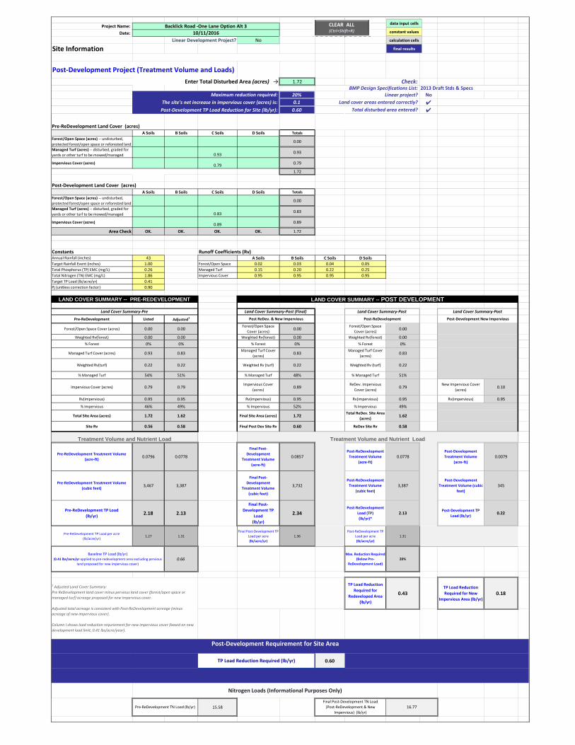
Project Name:
Date:
Linear Development Project? No
Site Information
Post‐Development Project (Treatment Volume and Loads)
1.72 ####
20% Linear project? No
The site's net increase in impervious cover (acres) is: 0.1 ✔Post‐Development TP Load Reduction for Site (lb/yr): 0.60 ✔
Pre‐ReDevelopment Land Cover (acres)A Soils B Soils C Soils D Soils Totals
Forest/Open Space (acres) ‐‐ undisturbed,
protected forest/open space or reforested land0.00
Managed Turf (acres) ‐‐ disturbed, graded for
yards or other turf to be mowed/managed 0.930.93
Impervious Cover (acres)0.79
0.79
1.72
Post‐Development Land Cover (acres)A Soils B Soils C Soils D Soils Totals
Forest/Open Space (acres) ‐‐ undisturbed,
protected forest/open space or reforested land0.00
Managed Turf (acres) ‐‐ disturbed, graded for
yards or other turf to be mowed/managed 0.830.83
Impervious Cover (acres)0.89
0.89
Area Check OK. OK. OK. OK. 1.72
Constants Runoff Coefficients (Rv)Annual Rainfall (inches) 43 A Soils B Soils C Soils D Soils
Target Rainfall Event (inches) 1.00 Forest/Open Space 0.02 0.03 0.04 0.05
Total Phosphorus (TP) EMC (mg/L) 0.26 Managed Turf 0.15 0.20 0.22 0.25
Total Nitrogen (TN) EMC (mg/L) 1.86 Impervious Cover 0.95 0.95 0.95 0.95
Target TP Load (lb/acre/yr) 0.41
Pj (unitless correction factor) 0.90
Pre‐ReDevelopment Listed Adjusted1
Forest/Open Space Cover (acres) 0.00 0.00Forest/Open Space
Cover (acres)0.00
Forest/Open Space
Cover (acres)0.00
Weighted Rv(forest) 0.00 0.00 Weighted Rv(forest) 0.00 Weighted Rv(forest) 0.00
% Forest 0% 0% % Forest 0% % Forest 0%
Managed Turf Cover (acres) 0.93 0.83Managed Turf Cover
(acres)0.83
Managed Turf Cover
(acres)0.83
Weighted Rv(turf) 0.22 0.22 Weighted Rv (turf) 0.22 Weighted Rv (turf) 0.22
% Managed Turf 54% 51% % Managed Turf 48% % Managed Turf 51%
Impervious Cover (acres) 0.79 0.79Impervious Cover
(acres)0.89
ReDev. Impervious
Cover (acres)0.79
New Impervious Cover
(acres)0.10
Rv(impervious) 0.95 0.95 Rv(impervious) 0.95 Rv(impervious) 0.95 Rv(impervious) 0.95
% Impervious 46% 49% % Impervious 52% % Impervious 49%
Total Site Area (acres) 1.72 1.62 Final Site Area (acres) 1.72Total ReDev. Site Area
(acres)1.62
Site Rv 0.56 0.58 Final Post Dev Site Rv 0.60 ReDev Site Rv 0.58
Pre‐ReDevelopment Treatment Volume
(acre‐ft) 0.0796 0.0778
Final Post‐
Development
Treatment Volume
(acre‐ft)
0.0857Post‐ReDevelopment
Treatment Volume
(acre‐ft)
0.0778Post‐Development
Treatment Volume
(acre‐ft)
0.0079
Pre‐ReDevelopment Treatment Volume
(cubic feet) 3,467 3,387
Final Post‐
Development
Treatment Volume
(cubic feet)
3,732Post‐ReDevelopment
Treatment Volume
(cubic feet)
3,387Post‐Development
Treatment Volume (cubic
feet)
345
Pre‐ReDevelopment TP Load
(lb/yr)2.18 2.13
Final Post‐
Development TP
Load
(lb/yr)
2.34Post‐ReDevelopment
Load (TP)
(lb/yr)*
2.13Post‐Development TP
Load (lb/yr)0.22
Pre‐ReDevelopment TP Load per acre
(lb/acre/yr)1.27 1.31
Final Post‐Development TP
Load per acre
(lb/acre/yr)
1.36
Post‐ReDevelopment TP
Load per acre
(lb/acre/yr)
1.31
0.66Max. Reduction Required
(Below Pre‐
ReDevelopment Load)
20%
TP Load Reduction
Required for
Redeveloped Area
(lb/yr)
0.43TP Load Reduction
Required for New
Impervious Area (lb/yr)0.18
0.60
N/A
15.58
Backlick Road ‐One Lane Option Alt 3
10/11/2016
LAND COVER SUMMARY -- POST DEVELOPMENTLAND COVER SUMMARY -- PRE-REDEVELOPMENT
Maximum reduction required:
Enter Total Disturbed Area (acres) → Check:
Land cover areas entered correctly?
Total disturbed area entered?
BMP Design Specifications List:
Linear Project TP Load Reduction Required (lb/yr):
Treatment Volume and Nutrient Load
Land Cover Summary‐Post (Final)
2013 Draft Stds & Specs
Land Cover Summary‐Pre
Pre‐ReDevelopment TN Load (lb/yr)
Final Post‐Development TN Load
(Post‐ReDevelopment & New
Impervious) (lb/yr)
16.77
Land Cover Summary‐Post
Post‐ReDevelopment
TP Load Reduction Required (lb/yr)
Post‐Development Requirement for Site Area
Nitrogen Loads (Informational Purposes Only)
Baseline TP Load (lb/yr)(0.41 lbs/acre/yr applied to pre‐redevelopment area excluding pervious
land proposed for new impervious cover)
1 Adjusted Land Cover Summary:
Pre ReDevelopment land cover minus pervious land cover (forest/open space or
managed turf) acreage proposed for new impervious cover.
Adjusted total acreage is consistent with Post‐ReDevelopment acreage (minus
acreage of new impervious cover).
Column I shows load reduction requriement for new impervious cover (based on new
development load limit, 0.41 lbs/acre/year).
Post ReDev. & New Impervious
Treatment Volume and Nutrient Load
Land Cover Summary‐Post
Post‐Development New Impervious
CLEAR ALL(Ctrl+Shift+R)
data input cells
constant values
calculation cells
final results
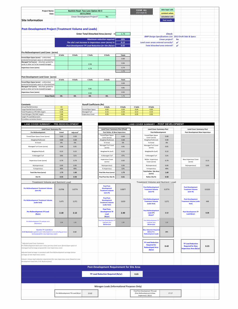
Project Name:
Date:
Linear Development Project? No
Site Information
Post‐Development Project (Treatment Volume and Loads)
1.73 ####
20% Linear project? No
The site's net increase in impervious cover (acres) is: 0.13 ✔Post‐Development TP Load Reduction for Site (lb/yr): 0.65 ✔
Pre‐ReDevelopment Land Cover (acres)A Soils B Soils C Soils D Soils Totals
Forest/Open Space (acres) ‐‐ undisturbed,
protected forest/open space or reforested land0.00
Managed Turf (acres) ‐‐ disturbed, graded for
yards or other turf to be mowed/managed 0.940.94
Impervious Cover (acres)0.79
0.79
1.73
Post‐Development Land Cover (acres)A Soils B Soils C Soils D Soils Totals
Forest/Open Space (acres) ‐‐ undisturbed,
protected forest/open space or reforested land0.00
Managed Turf (acres) ‐‐ disturbed, graded for
yards or other turf to be mowed/managed 0.810.81
Impervious Cover (acres)0.92
0.92
Area Check OK. OK. OK. OK. 1.73
Constants Runoff Coefficients (Rv)Annual Rainfall (inches) 43 A Soils B Soils C Soils D Soils
Target Rainfall Event (inches) 1.00 Forest/Open Space 0.02 0.03 0.04 0.05
Total Phosphorus (TP) EMC (mg/L) 0.26 Managed Turf 0.15 0.20 0.22 0.25
Total Nitrogen (TN) EMC (mg/L) 1.86 Impervious Cover 0.95 0.95 0.95 0.95
Target TP Load (lb/acre/yr) 0.41
Pj (unitless correction factor) 0.90
Pre‐ReDevelopment Listed Adjusted1
Forest/Open Space Cover (acres) 0.00 0.00Forest/Open Space
Cover (acres)0.00
Forest/Open Space
Cover (acres)0.00
Weighted Rv(forest) 0.00 0.00 Weighted Rv(forest) 0.00 Weighted Rv(forest) 0.00
% Forest 0% 0% % Forest 0% % Forest 0%
Managed Turf Cover (acres) 0.94 0.81Managed Turf Cover
(acres)0.81
Managed Turf Cover
(acres)0.81
Weighted Rv(turf) 0.22 0.22 Weighted Rv (turf) 0.22 Weighted Rv (turf) 0.22
% Managed Turf 54% 51% % Managed Turf 47% % Managed Turf 51%
Impervious Cover (acres) 0.79 0.79Impervious Cover
(acres)0.92
ReDev. Impervious
Cover (acres)0.79
New Impervious Cover
(acres)0.13
Rv(impervious) 0.95 0.95 Rv(impervious) 0.95 Rv(impervious) 0.95 Rv(impervious) 0.95
% Impervious 46% 49% % Impervious 53% % Impervious 49%
Total Site Area (acres) 1.73 1.60 Final Site Area (acres) 1.73Total ReDev. Site Area
(acres)1.60
Site Rv 0.55 0.58 Final Post Dev Site Rv 0.61 ReDev Site Rv 0.58
Pre‐ReDevelopment Treatment Volume
(acre‐ft) 0.0798 0.0774
Final Post‐
Development
Treatment Volume
(acre‐ft)
0.0877Post‐ReDevelopment
Treatment Volume
(acre‐ft)
0.0774Post‐Development
Treatment Volume
(acre‐ft)
0.0103
Pre‐ReDevelopment Treatment Volume
(cubic feet) 3,475 3,371
Final Post‐
Development
Treatment Volume
(cubic feet)
3,819Post‐ReDevelopment
Treatment Volume
(cubic feet)
3,371Post‐Development
Treatment Volume (cubic
feet)
448
Pre‐ReDevelopment TP Load
(lb/yr)2.18 2.12
Final Post‐
Development TP
Load
(lb/yr)
2.40Post‐ReDevelopment
Load (TP)
(lb/yr)*
2.12Post‐Development TP
Load (lb/yr)0.28
Pre‐ReDevelopment TP Load per acre
(lb/acre/yr)1.26 1.32
Final Post‐Development TP
Load per acre
(lb/acre/yr)
1.39
Post‐ReDevelopment TP
Load per acre
(lb/acre/yr)
1.32
0.66Max. Reduction Required
(Below Pre‐
ReDevelopment Load)
20%
TP Load Reduction
Required for
Redeveloped Area
(lb/yr)
0.42TP Load Reduction
Required for New
Impervious Area (lb/yr)0.23
0.65
N/A
15.62
Backlick Road ‐Two Lane Option Alt 3
10/11/2016
LAND COVER SUMMARY -- POST DEVELOPMENTLAND COVER SUMMARY -- PRE-REDEVELOPMENT
Maximum reduction required:
Enter Total Disturbed Area (acres) → Check:
Land cover areas entered correctly?
Total disturbed area entered?
BMP Design Specifications List:
Linear Project TP Load Reduction Required (lb/yr):
Treatment Volume and Nutrient Load
Land Cover Summary‐Post (Final)
2013 Draft Stds & Specs
Land Cover Summary‐Pre
Pre‐ReDevelopment TN Load (lb/yr)
Final Post‐Development TN Load
(Post‐ReDevelopment & New
Impervious) (lb/yr)
17.17
Land Cover Summary‐Post
Post‐ReDevelopment
TP Load Reduction Required (lb/yr)
Post‐Development Requirement for Site Area
Nitrogen Loads (Informational Purposes Only)
Baseline TP Load (lb/yr)(0.41 lbs/acre/yr applied to pre‐redevelopment area excluding pervious
land proposed for new impervious cover)
1 Adjusted Land Cover Summary:
Pre ReDevelopment land cover minus pervious land cover (forest/open space or
managed turf) acreage proposed for new impervious cover.
Adjusted total acreage is consistent with Post‐ReDevelopment acreage (minus
acreage of new impervious cover).
Column I shows load reduction requriement for new impervious cover (based on new
development load limit, 0.41 lbs/acre/year).
Post ReDev. & New Impervious
Treatment Volume and Nutrient Load
Land Cover Summary‐Post
Post‐Development New Impervious
CLEAR ALL(Ctrl+Shift+R)
data input cells
constant values
calculation cells
final results
ATTACHMENT 9
BRIDGE ALTERNATES MATRIX AND MOT OPTIONS MATRIX
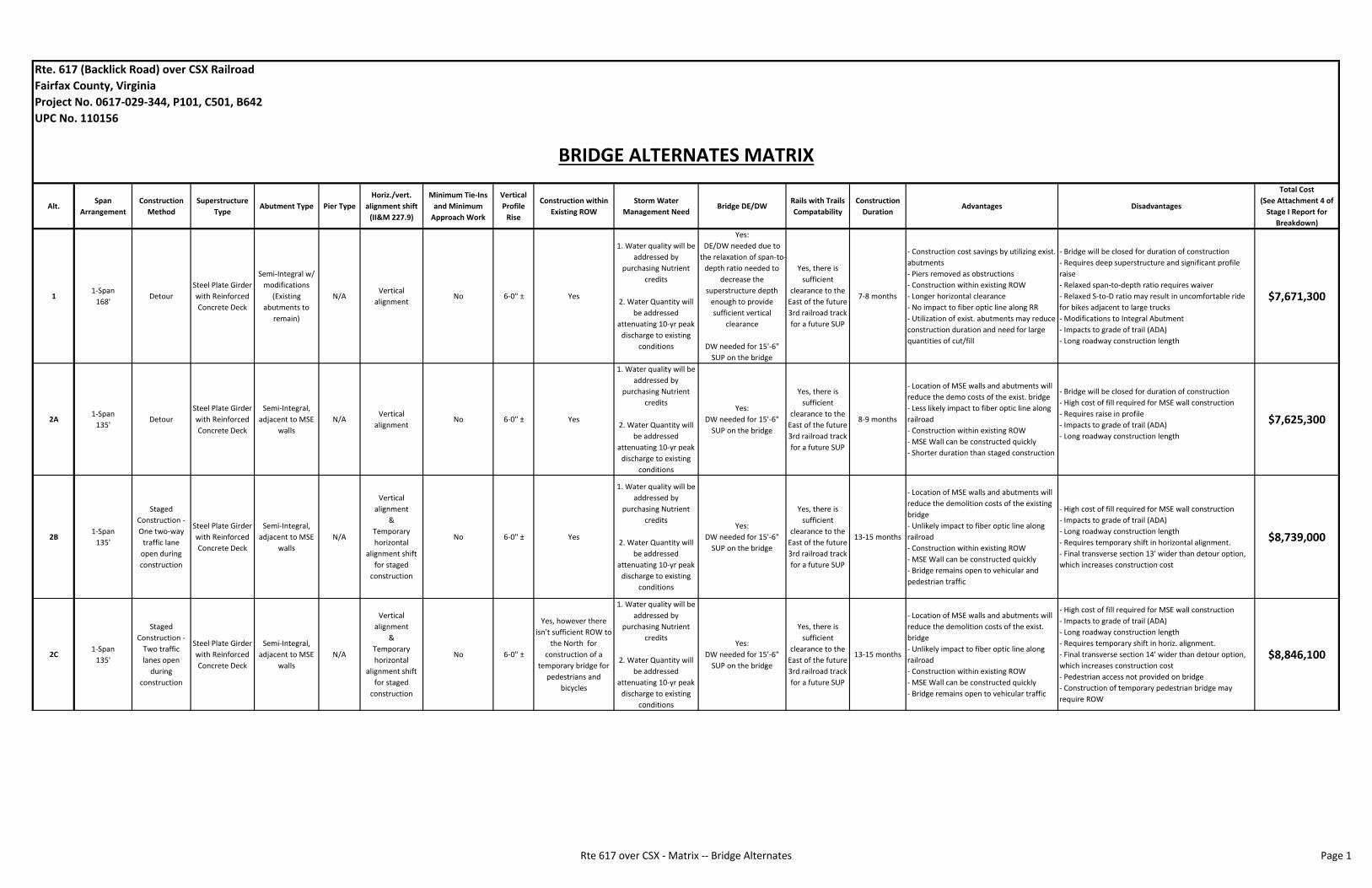
Alt.Span
Arrangement
Construction
Method
Superstructure
TypeAbutment Type Pier Type
Horiz./vert.
alignment shift
(II&M 227.9)
Minimum Tie‐Ins
and Minimum
Approach Work
Vertical
Profile
Rise
Construction within
Existing ROW
Storm Water
Management NeedBridge DE/DW
Rails with Trails
Compatability
Construction
DurationAdvantages Disadvantages
Total Cost
(See Attachment 4 of
Stage I Report for
Breakdown)
11‐Span
168'Detour
Steel Plate Girder
with Reinforced
Concrete Deck
Semi‐Integral w/
modifications
(Existing
abutments to
remain)
N/AVertical
alignmentNo 6‐0" ± Yes
1. Water quality will be
addressed by
purchasing Nutrient
credits
2. Water Quantity will
be addressed
attenuating 10‐yr peak
discharge to existing
conditions
Yes:
DE/DW needed due to
the relaxation of span‐to‐
depth ratio needed to
decrease the
superstructure depth
enough to provide
sufficient vertical
clearance
DW needed for 15'‐6"
SUP on the bridge
Yes, there is
sufficient
clearance to the
East of the future
3rd railroad track
for a future SUP
7‐8 months
‐ Construction cost savings by utilizing exist.
abutments
‐ Piers removed as obstructions
‐ Construction within existing ROW
‐ Longer horizontal clearance
‐ No impact to fiber optic line along RR
‐ Utilization of exist. abutments may reduce
construction duration and need for large
quantities of cut/fill
‐ Bridge will be closed for duration of construction
‐ Requires deep superstructure and significant profile
raise
‐ Relaxed span‐to‐depth ratio requires waiver
‐ Relaxed S‐to‐D ratio may result in uncomfortable ride
for bikes adjacent to large trucks
‐ Modifications to Integral Abutment
‐ Impacts to grade of trail (ADA)
‐ Long roadway construction length
$7,671,300
2A1‐Span
135'Detour
Steel Plate Girder
with Reinforced
Concrete Deck
Semi‐Integral,
adjacent to MSE
walls
N/AVertical
alignmentNo 6‐0" ± Yes
1. Water quality will be
addressed by
purchasing Nutrient
credits
2. Water Quantity will
be addressed
attenuating 10‐yr peak
discharge to existing
conditions
Yes:
DW needed for 15'‐6"
SUP on the bridge
Yes, there is
sufficient
clearance to the
East of the future
3rd railroad track
for a future SUP
8‐9 months
‐ Location of MSE walls and abutments will
reduce the demo costs of the exist. bridge
‐ Less likely impact to fiber optic line along
railroad
‐ Construction within existing ROW
‐ MSE Wall can be constructed quickly
‐ Shorter duration than staged construction
‐ Bridge will be closed for duration of construction
‐ High cost of fill required for MSE wall construction
‐ Requires raise in profile
‐ Impacts to grade of trail (ADA)
‐ Long roadway construction length
$7,625,300
2B1‐Span
135'
Staged
Construction ‐
One two‐way
traffic lane
open during
construction
Steel Plate Girder
with Reinforced
Concrete Deck
Semi‐Integral,
adjacent to MSE
walls
N/A
Vertical
alignment
&
Temporary
horizontal
alignment shift
for staged
construction
No 6‐0" ± Yes
1. Water quality will be
addressed by
purchasing Nutrient
credits
2. Water Quantity will
be addressed
attenuating 10‐yr peak
discharge to existing
conditions
Yes:
DW needed for 15'‐6"
SUP on the bridge
Yes, there is
sufficient
clearance to the
East of the future
3rd railroad track
for a future SUP
13‐15 months
‐ Location of MSE walls and abutments will
reduce the demolition costs of the existing
bridge
‐ Unlikely impact to fiber optic line along
railroad
‐ Construction within existing ROW
‐ MSE Wall can be constructed quickly
‐ Bridge remains open to vehicular and
pedestrian traffic
‐ High cost of fill required for MSE wall construction
‐ Impacts to grade of trail (ADA)
‐ Long roadway construction length
‐ Requires temporary shift in horizontal alignment.
‐ Final transverse section 13' wider than detour option,
which increases construction cost
$8,739,000
2C1‐Span
135'
Staged
Construction ‐
Two traffic
lanes open
during
construction
Steel Plate Girder
with Reinforced
Concrete Deck
Semi‐Integral,
adjacent to MSE
walls
N/A
Vertical
alignment
&
Temporary
horizontal
alignment shift
for staged
construction
No 6‐0" ±
Yes, however there
isn't sufficient ROW to
the North for
construction of a
temporary bridge for
pedestrians and
bicycles
1. Water quality will be
addressed by
purchasing Nutrient
credits
2. Water Quantity will
be addressed
attenuating 10‐yr peak
discharge to existing
conditions
Yes:
DW needed for 15'‐6"
SUP on the bridge
Yes, there is
sufficient
clearance to the
East of the future
3rd railroad track
for a future SUP
13‐15 months
‐ Location of MSE walls and abutments will
reduce the demolition costs of the exist.
bridge
‐ Unlikely impact to fiber optic line along
railroad
‐ Construction within existing ROW
‐ MSE Wall can be constructed quickly
‐ Bridge remains open to vehicular traffic
‐ High cost of fill required for MSE wall construction
‐ Impacts to grade of trail (ADA)
‐ Long roadway construction length
‐ Requires temporary shift in horiz. alignment.
‐ Final transverse section 14' wider than detour option,
which increases construction cost
‐ Pedestrian access not provided on bridge
‐ Construction of temporary pedestrian bridge may
require ROW
$8,846,100
Rte. 617 (Backlick Road) over CSX Railroad
Fairfax County, Virginia
Project No. 0617‐029‐344, P101, C501, B642
UPC No. 110156
BRIDGE ALTERNATES MATRIX
Rte 617 over CSX ‐ Matrix ‐‐ Bridge Alternates Page 1
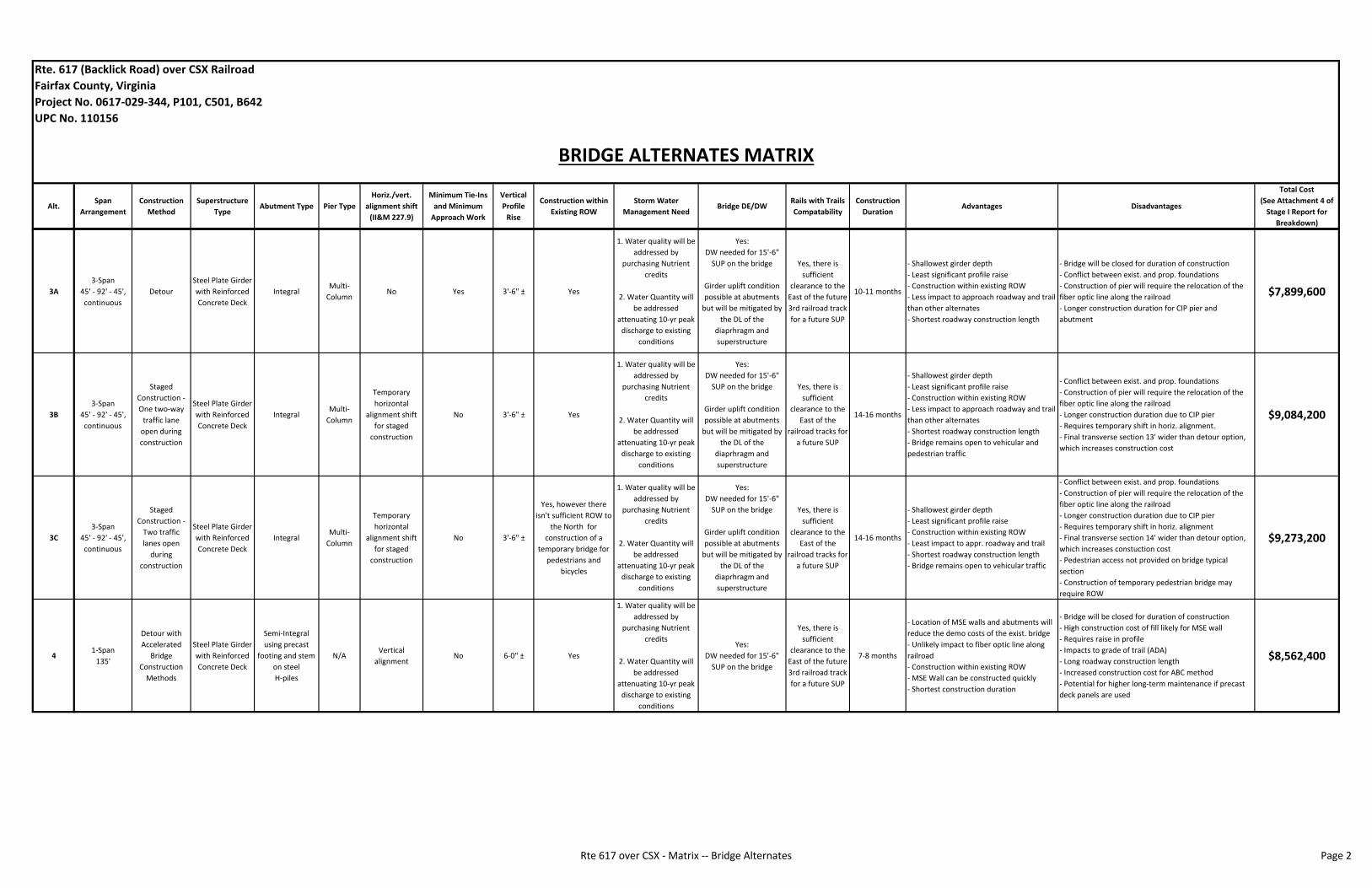
Alt.Span
Arrangement
Construction
Method
Superstructure
TypeAbutment Type Pier Type
Horiz./vert.
alignment shift
(II&M 227.9)
Minimum Tie‐Ins
and Minimum
Approach Work
Vertical
Profile
Rise
Construction within
Existing ROW
Storm Water
Management NeedBridge DE/DW
Rails with Trails
Compatability
Construction
DurationAdvantages Disadvantages
Total Cost
(See Attachment 4 of
Stage I Report for
Breakdown)
Rte. 617 (Backlick Road) over CSX Railroad
Fairfax County, Virginia
Project No. 0617‐029‐344, P101, C501, B642
UPC No. 110156
BRIDGE ALTERNATES MATRIX
3A
3‐Span
45' ‐ 92' ‐ 45',
continuous
Detour
Steel Plate Girder
with Reinforced
Concrete Deck
IntegralMulti‐
ColumnNo Yes 3'‐6" ± Yes
1. Water quality will be
addressed by
purchasing Nutrient
credits
2. Water Quantity will
be addressed
attenuating 10‐yr peak
discharge to existing
conditions
Yes:
DW needed for 15'‐6"
SUP on the bridge
Girder uplift condition
possible at abutments
but will be mitigated by
the DL of the
diaprhragm and
superstructure
Yes, there is
sufficient
clearance to the
East of the future
3rd railroad track
for a future SUP
10‐11 months
‐ Shallowest girder depth
‐ Least significant profile raise
‐ Construction within existing ROW
‐ Less impact to approach roadway and trail
than other alternates
‐ Shortest roadway construction length
‐ Bridge will be closed for duration of construction
‐ Conflict between exist. and prop. foundations
‐ Construction of pier will require the relocation of the
fiber optic line along the railroad
‐ Longer construction duration for CIP pier and
abutment
$7,899,600
3B
3‐Span
45' ‐ 92' ‐ 45',
continuous
Staged
Construction ‐
One two‐way
traffic lane
open during
construction
Steel Plate Girder
with Reinforced
Concrete Deck
IntegralMulti‐
Column
Temporary
horizontal
alignment shift
for staged
construction
No 3'‐6" ± Yes
1. Water quality will be
addressed by
purchasing Nutrient
credits
2. Water Quantity will
be addressed
attenuating 10‐yr peak
discharge to existing
conditions
Yes:
DW needed for 15'‐6"
SUP on the bridge
Girder uplift condition
possible at abutments
but will be mitigated by
the DL of the
diaprhragm and
superstructure
Yes, there is
sufficient
clearance to the
East of the
railroad tracks for
a future SUP
14‐16 months
‐ Shallowest girder depth
‐ Least significant profile raise
‐ Construction within existing ROW
‐ Less impact to approach roadway and trail
than other alternates
‐ Shortest roadway construction length
‐ Bridge remains open to vehicular and
pedestrian traffic
‐ Conflict between exist. and prop. foundations
‐ Construction of pier will require the relocation of the
fiber optic line along the railroad
‐ Longer construction duration due to CIP pier
‐ Requires temporary shift in horiz. alignment.
‐ Final transverse section 13' wider than detour option,
which increases construction cost
$9,084,200
3C
3‐Span
45' ‐ 92' ‐ 45',
continuous
Staged
Construction ‐
Two traffic
lanes open
during
construction
Steel Plate Girder
with Reinforced
Concrete Deck
IntegralMulti‐
Column
Temporary
horizontal
alignment shift
for staged
construction
No 3'‐6" ±
Yes, however there
isn't sufficient ROW to
the North for
construction of a
temporary bridge for
pedestrians and
bicycles
1. Water quality will be
addressed by
purchasing Nutrient
credits
2. Water Quantity will
be addressed
attenuating 10‐yr peak
discharge to existing
conditions
Yes:
DW needed for 15'‐6"
SUP on the bridge
Girder uplift condition
possible at abutments
but will be mitigated by
the DL of the
diaprhragm and
superstructure
Yes, there is
sufficient
clearance to the
East of the
railroad tracks for
a future SUP
14‐16 months
‐ Shallowest girder depth
‐ Least significant profile raise
‐ Construction within existing ROW
‐ Least impact to appr. roadway and trail
‐ Shortest roadway construction length
‐ Bridge remains open to vehicular traffic
‐ Conflict between exist. and prop. foundations
‐ Construction of pier will require the relocation of the
fiber optic line along the railroad
‐ Longer construction duration due to CIP pier
‐ Requires temporary shift in horiz. alignment
‐ Final transverse section 14' wider than detour option,
which increases constuction cost
‐ Pedestrian access not provided on bridge typical
section
‐ Construction of temporary pedestrian bridge may
require ROW
$9,273,200
41‐Span
135'
Detour with
Accelerated
Bridge
Construction
Methods
Steel Plate Girder
with Reinforced
Concrete Deck
Semi‐Integral
using precast
footing and stem
on steel
H‐piles
N/AVertical
alignmentNo 6‐0" ± Yes
1. Water quality will be
addressed by
purchasing Nutrient
credits
2. Water Quantity will
be addressed
attenuating 10‐yr peak
discharge to existing
conditions
Yes:
DW needed for 15'‐6"
SUP on the bridge
Yes, there is
sufficient
clearance to the
East of the future
3rd railroad track
for a future SUP
7‐8 months
‐ Location of MSE walls and abutments will
reduce the demo costs of the exist. bridge
‐ Unlikely impact to fiber optic line along
railroad
‐ Construction within existing ROW
‐ MSE Wall can be constructed quickly
‐ Shortest construction duration
‐ Bridge will be closed for duration of construction
‐ High construction cost of fill likely for MSE wall
‐ Requires raise in profile
‐ Impacts to grade of trail (ADA)
‐ Long roadway construction length
‐ Increased construction cost for ABC method
‐ Potential for higher long‐term maintenance if precast
deck panels are used
$8,562,400
Rte 617 over CSX ‐ Matrix ‐‐ Bridge Alternates Page 2

Option Maintenance of TrafficConstruction within Existing
ROWConstruction Duration Advantages Disadvantages Estimated Cost
MOT A Detour
Yes.
Minimal need for
construction easements
No time added.
• Reduced project duration and construction cost.
• Reduce risk and improved safety to construction workers
and motorists.
• Reduced environmental impacts from less complicated
construction and fewer vehicles in construction area.
• Reduced construction cost due to reduced bridge width.
Final bridge width will be 45 feet.
• Detour will have modest effect on area congestion (see
Traffic Study).
• Lack of egress from Newington area. Egress will be limited
to the CSX underpass or the Newington residential area.
• Special provisions will be needed for bike / pedestrian
access.
MOT Total:
$199,445
MOT B1Staged with One‐Lane One‐
Way with Temporary Signal
Yes.
Minimal need for
construction easements
4‐6 months longer than
MOT Option A
• Maintains bike and pedestrian access.
• No detour of traffic.
• Increased risk to workers and motorists than detour.
• Longer project duration and greater construction cost
than detour.
• Temporary traffic signal needed.
• Traffic heading southbound is expected to create queues
that will block through traffic on Fairfax County Parkway.
• Wider bridge width. Final bridge width will be 57 feet.
MOT Total:
$344,625
MOT B2Staged with One‐Lane One‐
Way by Time of Day
Yes.
Minimal need for
construction easements
4‐6 months longer than
MOT Option A
• Maintains bike and pedestrian access.
• Traffic heading SB not expected to queue or block Fairfax
County Parkway traffic.
• No need for temporary traffic signal.
• Detour by time of day necessary. Potentially confusing
signing and marketing necessary.
• Increased risk to workers and motorists than detour.
• Longer project duration and greater construction cost
than detour.
• Wider bridge width. Final bridge width will be 57 feet.
MOT Total:
$323,805
MOT C
Staged with Two‐Lane Two‐
Way
and no Bike or Pedestrian
Access
Yes.
Minimal need for
construction easements
4‐6 months longer than
MOT Option A
• Best vehicular capacity over bridge; most similar to
current conditions.
• Signing and marking less complicated.
• Increased risk to workers and motorists than detour.
• Longer project duration and greater construction cost
than detour.
• No access for bike or pedestrians.
• Widest bridge width. Final bridge width will be 61 feet.
MOT Total:
$322,325
MOT OPTIONS MATRIX
Rte. 617 (Backlick Road) over CSX Railroad
Fairfax County, Virginia
Project No. 0617‐029‐344, P101, C501, B642
UPC No. 110156
Rte 617 over CSX ‐ Matrix ‐‐ MOT Options Page 1

ATTACHMENT 10
UTILITY CONFLICT MATRIX
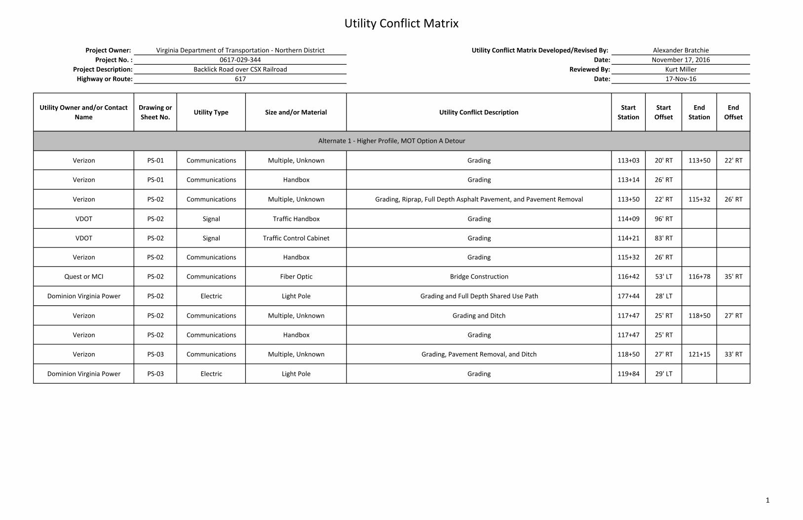
Utility Conflict Matrix
Project Owner: Utility Conflict Matrix Developed/Revised By:
Project No. : Date:
Project Description: Reviewed By:
Highway or Route: Date:
Utility Owner and/or Contact
Name
Drawing or
Sheet No. Utility Type Size and/or Material Utility Conflict Description
Start
Station
Start
Offset
End
Station
End
Offset
Verizon PS‐01 Communications Multiple, Unknown Grading 113+03 20' RT 113+50 22' RT
Verizon PS‐01 Communications Handbox Grading 113+14 26' RT
Verizon PS‐02 Communications Multiple, Unknown Grading, Riprap, Full Depth Asphalt Pavement, and Pavement Removal 113+50 22' RT 115+32 26' RT
VDOT PS‐02 Signal Traffic Handbox Grading 114+09 96' RT
VDOT PS‐02 Signal Traffic Control Cabinet Grading 114+21 83' RT
Verizon PS‐02 Communications Handbox Grading 115+32 26' RT
Quest or MCI PS‐02 Communications Fiber Optic Bridge Construction 116+42 53' LT 116+78 35' RT
Dominion Virginia Power PS‐02 Electric Light Pole Grading and Full Depth Shared Use Path 177+44 28' LT
Verizon PS‐02 Communications Multiple, Unknown Grading and Ditch 117+47 25' RT 118+50 27' RT
Verizon PS‐02 Communications Handbox Grading 117+47 25' RT
Verizon PS‐03 Communications Multiple, Unknown Grading, Pavement Removal, and Ditch 118+50 27' RT 121+15 33' RT
Dominion Virginia Power PS‐03 Electric Light Pole Grading 119+84 29' LT
Alexander Bratchie
November 17, 2016
Kurt Miller
17‐Nov‐16
Alternate 1 ‐ Higher Profile, MOT Option A Detour
Virginia Department of Transportation ‐ Northern District
0617‐029‐344
Backlick Road over CSX Railroad
617
1
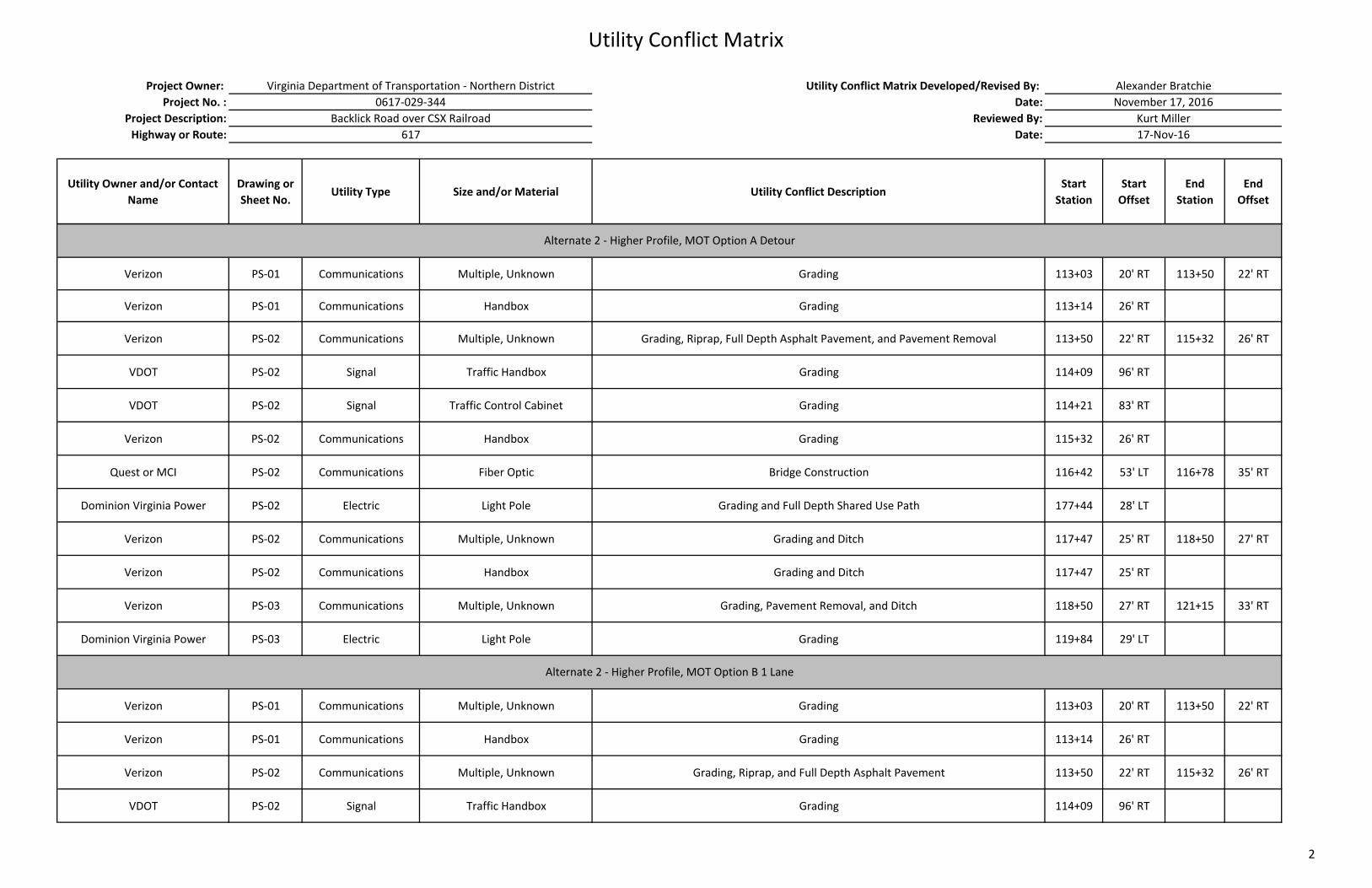
Utility Conflict Matrix
Project Owner: Utility Conflict Matrix Developed/Revised By:
Project No. : Date:
Project Description: Reviewed By:
Highway or Route: Date:
Utility Owner and/or Contact
Name
Drawing or
Sheet No. Utility Type Size and/or Material Utility Conflict Description
Start
Station
Start
Offset
End
Station
End
Offset
Alexander Bratchie
November 17, 2016
Kurt Miller
17‐Nov‐16
Virginia Department of Transportation ‐ Northern District
0617‐029‐344
Backlick Road over CSX Railroad
617
Verizon PS‐01 Communications Multiple, Unknown Grading 113+03 20' RT 113+50 22' RT
Verizon PS‐01 Communications Handbox Grading 113+14 26' RT
Verizon PS‐02 Communications Multiple, Unknown Grading, Riprap, Full Depth Asphalt Pavement, and Pavement Removal 113+50 22' RT 115+32 26' RT
VDOT PS‐02 Signal Traffic Handbox Grading 114+09 96' RT
VDOT PS‐02 Signal Traffic Control Cabinet Grading 114+21 83' RT
Verizon PS‐02 Communications Handbox Grading 115+32 26' RT
Quest or MCI PS‐02 Communications Fiber Optic Bridge Construction 116+42 53' LT 116+78 35' RT
Dominion Virginia Power PS‐02 Electric Light Pole Grading and Full Depth Shared Use Path 177+44 28' LT
Verizon PS‐02 Communications Multiple, Unknown Grading and Ditch 117+47 25' RT 118+50 27' RT
Verizon PS‐02 Communications Handbox Grading and Ditch 117+47 25' RT
Verizon PS‐03 Communications Multiple, Unknown Grading, Pavement Removal, and Ditch 118+50 27' RT 121+15 33' RT
Dominion Virginia Power PS‐03 Electric Light Pole Grading 119+84 29' LT
Verizon PS‐01 Communications Multiple, Unknown Grading 113+03 20' RT 113+50 22' RT
Verizon PS‐01 Communications Handbox Grading 113+14 26' RT
Verizon PS‐02 Communications Multiple, Unknown Grading, Riprap, and Full Depth Asphalt Pavement 113+50 22' RT 115+32 26' RT
VDOT PS‐02 Signal Traffic Handbox Grading 114+09 96' RT
Alternate 2 ‐ Higher Profile, MOT Option B 1 Lane
Alternate 2 ‐ Higher Profile, MOT Option A Detour
2

Utility Conflict Matrix
Project Owner: Utility Conflict Matrix Developed/Revised By:
Project No. : Date:
Project Description: Reviewed By:
Highway or Route: Date:
Utility Owner and/or Contact
Name
Drawing or
Sheet No. Utility Type Size and/or Material Utility Conflict Description
Start
Station
Start
Offset
End
Station
End
Offset
Alexander Bratchie
November 17, 2016
Kurt Miller
17‐Nov‐16
Virginia Department of Transportation ‐ Northern District
0617‐029‐344
Backlick Road over CSX Railroad
617
VDOT PS‐02 Signal Traffic Control Cabinet Grading 114+21 83' RT
Verizon PS‐02 Communications Handbox Grading 115+32 26' RT
Quest or MCI PS‐02 Communications Fiber Optic Bridge Construction 116+42 53' LT 116+78 35' RT
Dominion Virginia Power PS‐02 Electric Light Pole Grading and Full Depth Shared Use Path 177+44 28' LT
Verizon PS‐02 Communications Multiple, Unknown Grading and Ditch 117+47 25' RT 118+50 27' RT
Verizon PS‐02 Communications Handbox Grading 117+47 25' RT
Verizon PS‐03 Communications Multiple, Unknown Grading, Pavement Removal, and Ditch 118+50 27' RT 121+15 33' RT
Dominion Virginia Power PS‐03 Electric Light Pole Grading 119+84 29' LT
Verizon PS‐01 Communications Multiple, Unknown Grading 113+03 20' RT 113+50 22' RT
Verizon PS‐01 Communications Handbox Grading 113+14 26' RT
Verizon PS‐02 Communications Multiple, Unknown Grading, Riprap, and Full Depth Asphalt Pavement 113+50 22' RT 115+32 26' RT
VDOT PS‐02 Signal Traffic Handbox Grading 114+09 96' RT
VDOT PS‐02 Signal Traffic Control Cabinet Grading 114+21 83' RT
Verizon PS‐02 Communications Handbox Grading 115+32 26' RT
Quest or MCI PS‐02 Communications Fiber Optic Bridge Construction 116+42 53' LT 116+78 35' RT
Dominion Virginia Power PS‐02 Electric Light Pole Grading and Full Depth Shared Use Path 177+44 28' LT
Verizon PS‐02 Communications Multiple, Unknown Grading 117+47 25' RT 118+50 27' RT
Alternate 2 ‐ Higher Profile, MOT Option C 2 Lane
3
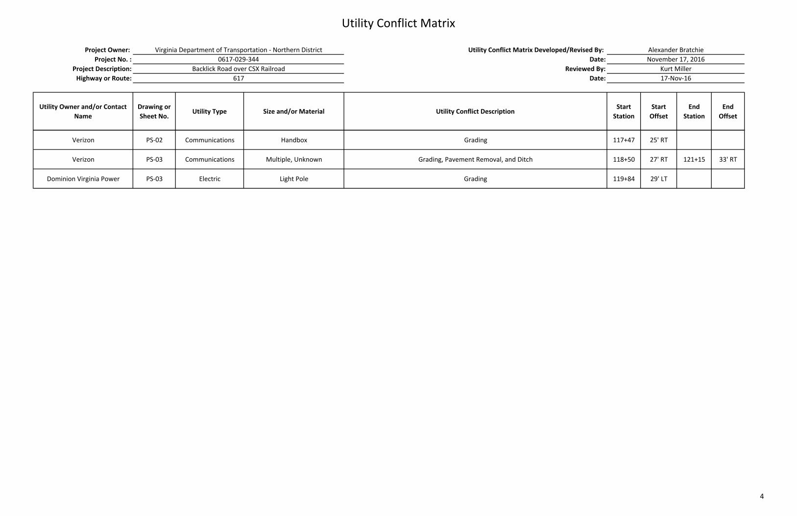
Utility Conflict Matrix
Project Owner: Utility Conflict Matrix Developed/Revised By:
Project No. : Date:
Project Description: Reviewed By:
Highway or Route: Date:
Utility Owner and/or Contact
Name
Drawing or
Sheet No. Utility Type Size and/or Material Utility Conflict Description
Start
Station
Start
Offset
End
Station
End
Offset
Alexander Bratchie
November 17, 2016
Kurt Miller
17‐Nov‐16
Virginia Department of Transportation ‐ Northern District
0617‐029‐344
Backlick Road over CSX Railroad
617
Verizon PS‐02 Communications Handbox Grading 117+47 25' RT
Verizon PS‐03 Communications Multiple, Unknown Grading, Pavement Removal, and Ditch 118+50 27' RT 121+15 33' RT
Dominion Virginia Power PS‐03 Electric Light Pole Grading 119+84 29' LT
4
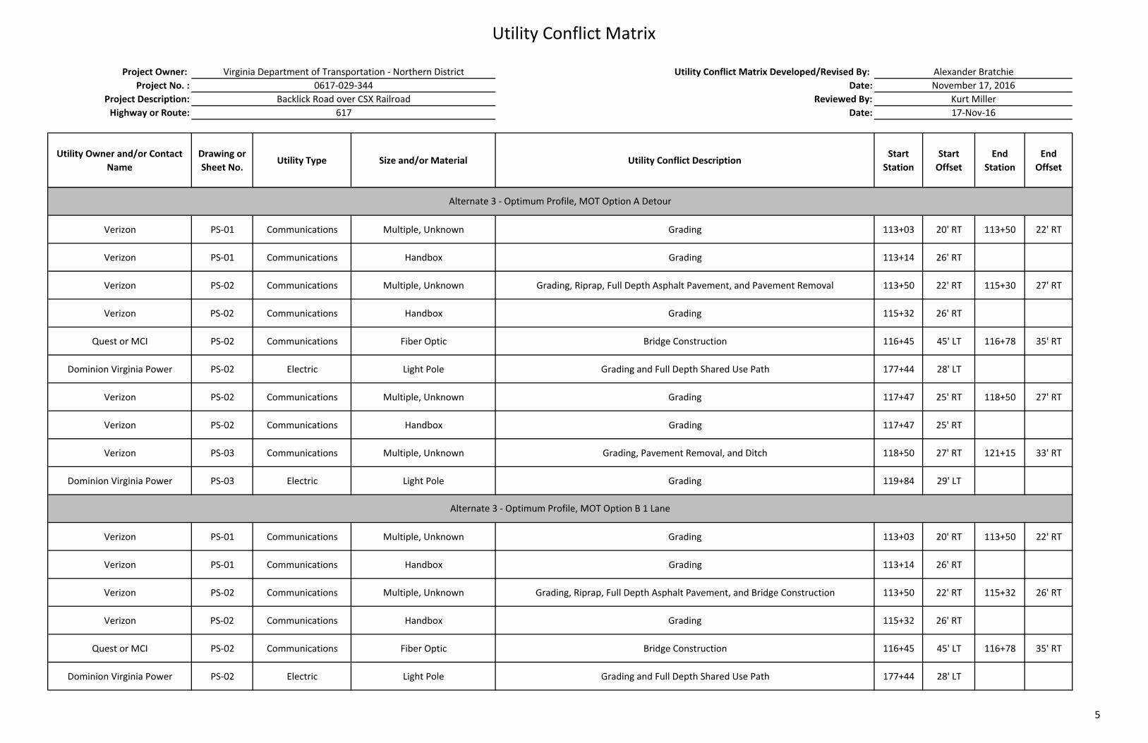
Utility Conflict Matrix
Project Owner: Utility Conflict Matrix Developed/Revised By:
Project No. : Date:
Project Description: Reviewed By:
Highway or Route: Date:
Utility Owner and/or Contact
Name
Drawing or
Sheet No. Utility Type Size and/or Material Utility Conflict Description
Start
Station
Start
Offset
End
Station
End
Offset
Alexander Bratchie
November 17, 2016
Kurt Miller
17‐Nov‐16
Virginia Department of Transportation ‐ Northern District
0617‐029‐344
Backlick Road over CSX Railroad
617
Verizon PS‐01 Communications Multiple, Unknown Grading 113+03 20' RT 113+50 22' RT
Verizon PS‐01 Communications Handbox Grading 113+14 26' RT
Verizon PS‐02 Communications Multiple, Unknown Grading, Riprap, Full Depth Asphalt Pavement, and Pavement Removal 113+50 22' RT 115+30 27' RT
Verizon PS‐02 Communications Handbox Grading 115+32 26' RT
Quest or MCI PS‐02 Communications Fiber Optic Bridge Construction 116+45 45' LT 116+78 35' RT
Dominion Virginia Power PS‐02 Electric Light Pole Grading and Full Depth Shared Use Path 177+44 28' LT
Verizon PS‐02 Communications Multiple, Unknown Grading 117+47 25' RT 118+50 27' RT
Verizon PS‐02 Communications Handbox Grading 117+47 25' RT
Verizon PS‐03 Communications Multiple, Unknown Grading, Pavement Removal, and Ditch 118+50 27' RT 121+15 33' RT
Dominion Virginia Power PS‐03 Electric Light Pole Grading 119+84 29' LT
Verizon PS‐01 Communications Multiple, Unknown Grading 113+03 20' RT 113+50 22' RT
Verizon PS‐01 Communications Handbox Grading 113+14 26' RT
Verizon PS‐02 Communications Multiple, Unknown Grading, Riprap, Full Depth Asphalt Pavement, and Bridge Construction 113+50 22' RT 115+32 26' RT
Verizon PS‐02 Communications Handbox Grading 115+32 26' RT
Quest or MCI PS‐02 Communications Fiber Optic Bridge Construction 116+45 45' LT 116+78 35' RT
Dominion Virginia Power PS‐02 Electric Light Pole Grading and Full Depth Shared Use Path 177+44 28' LT
Alternate 3 ‐ Optimum Profile, MOT Option A Detour
Alternate 3 ‐ Optimum Profile, MOT Option B 1 Lane
5

Utility Conflict Matrix
Project Owner: Utility Conflict Matrix Developed/Revised By:
Project No. : Date:
Project Description: Reviewed By:
Highway or Route: Date:
Utility Owner and/or Contact
Name
Drawing or
Sheet No. Utility Type Size and/or Material Utility Conflict Description
Start
Station
Start
Offset
End
Station
End
Offset
Alexander Bratchie
November 17, 2016
Kurt Miller
17‐Nov‐16
Virginia Department of Transportation ‐ Northern District
0617‐029‐344
Backlick Road over CSX Railroad
617
Verizon PS‐02 Communications Multiple, Unknown Grading, Bridge Construction, Ditch, and Full Depth Asphalt Pavement 117+47 25' RT 118+50 27' RT
Verizon PS‐02 Communications Handbox Grading and Bridge Construction 117+47 25' RT
Verizon PS‐03 Communications Multiple, Unknown Grading, Pavement Removal, and Ditch 118+50 27' RT 121+15 33' RT
Dominion Virginia Power PS‐03 Electric Light Pole Grading 119+84 29' LT
Verizon PS‐01 Communications Multiple, Unknown Grading 113+03 20' RT 113+50 22' RT
Verizon PS‐01 Communications Handbox Grading 113+14 26' RT
Verizon PS‐02 Communications Multiple, Unknown Grading, Riprap, Full Depth Asphalt Pavement, and Bridge Construction 113+50 22' RT 115+32 26' RT
Verizon PS‐02 Communications Handbox Grading 115+32 26' RT
Quest or MCI PS‐02 Communications Fiber Optic Bridge Construction 116+45 45' LT 116+78 35' RT
Dominion Virginia Power PS‐02 Electric Light Pole Grading and Full Depth Shared Use Path 177+44 28' LT
Verizon PS‐02 Communications Multiple, Unknown Grading, Bridge Construction, Pavement Removal, and Full Depth Asphalt Pavement 117+47 25' RT 118+50 27' RT
Verizon PS‐02 Communications Handbox Grading and Bridge Construction 117+47 25' RT
Verizon PS‐03 Communications Multiple, Unknown Grading, Pavement Removal, and Ditch 118+50 27' RT 121+15 33' RT
Dominion Virginia Power PS‐03 Electric Light Pole Grading 119+84 29' LT
Alternate 3 ‐ Optimum Profile, MOT Option C 2 Lane
6
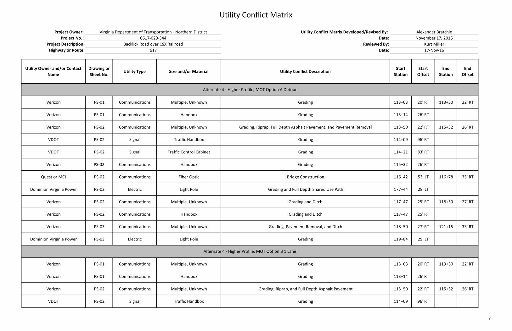
Utility Conflict Matrix
Project Owner: Utility Conflict Matrix Developed/Revised By:
Project No. : Date:
Project Description: Reviewed By:
Highway or Route: Date:
Utility Owner and/or Contact
Name
Drawing or
Sheet No. Utility Type Size and/or Material Utility Conflict Description
Start
Station
Start
Offset
End
Station
End
Offset
Alexander Bratchie
November 17, 2016
Kurt Miller
17‐Nov‐16
Virginia Department of Transportation ‐ Northern District
0617‐029‐344
Backlick Road over CSX Railroad
617
Verizon PS‐01 Communications Multiple, Unknown Grading 113+03 20' RT 113+50 22' RT
Verizon PS‐01 Communications Handbox Grading 113+14 26' RT
Verizon PS‐02 Communications Multiple, Unknown Grading, Riprap, Full Depth Asphalt Pavement, and Pavement Removal 113+50 22' RT 115+32 26' RT
VDOT PS‐02 Signal Traffic Handbox Grading 114+09 96' RT
VDOT PS‐02 Signal Traffic Control Cabinet Grading 114+21 83' RT
Verizon PS‐02 Communications Handbox Grading 115+32 26' RT
Quest or MCI PS‐02 Communications Fiber Optic Bridge Construction 116+42 53' LT 116+78 35' RT
Dominion Virginia Power PS‐02 Electric Light Pole Grading and Full Depth Shared Use Path 177+44 28' LT
Verizon PS‐02 Communications Multiple, Unknown Grading and Ditch 117+47 25' RT 118+50 27' RT
Verizon PS‐02 Communications Handbox Grading and Ditch 117+47 25' RT
Verizon PS‐03 Communications Multiple, Unknown Grading, Pavement Removal, and Ditch 118+50 27' RT 121+15 33' RT
Dominion Virginia Power PS‐03 Electric Light Pole Grading 119+84 29' LT
Verizon PS‐01 Communications Multiple, Unknown Grading 113+03 20' RT 113+50 22' RT
Verizon PS‐01 Communications Handbox Grading 113+14 26' RT
Verizon PS‐02 Communications Multiple, Unknown Grading, Riprap, and Full Depth Asphalt Pavement 113+50 22' RT 115+32 26' RT
VDOT PS‐02 Signal Traffic Handbox Grading 114+09 96' RT
Alternate 4 ‐ Higher Profile, MOT Option A Detour
Alternate 4 ‐ Higher Profile, MOT Option B 1 Lane
7
bwilson
Text Box