SSW-06 V1.6X - Profibus DP, DeviceNet and EtherNet/IP for Profibus DP, DeviceNet and EtherNet/IP...
35
Motors | Energy | Automation | Coatings Soft-Starter SSW-06 V1.6X - Profibus DP, DeviceNet and EtherNet/IP Fieldbus Communication Manual Language: English Document: 0899.5844 / 06
Transcript of SSW-06 V1.6X - Profibus DP, DeviceNet and EtherNet/IP for Profibus DP, DeviceNet and EtherNet/IP...
Motors | Energy | Automation | Coatings
Soft-Starter
SSW-06 V1.6X - Profibus DP, DeviceNet and EtherNet/IP
Fieldbus Communication Manual Language: English Document: 0899.5844 / 06

Profibus DP, DeviceNet and EtherNet/IP Communication Manual
Series: SSW-06 V1.6X
Language: English
Document Number: 0899.5844 / 06
Publication Date: 11/2009

Summary
SUMMARY
INFORMATION ABOUT THE MANUAL.........................................................5 FIELDBUS NETWORKS ............................................................................................................................... 5 ABBREVIATIONS AND DEFINITIONS......................................................................................................... 5 NUMERICAL PRESENTATION .................................................................................................................... 5
1 FIELDBUS KIT FOR THE SOFT-STARTER SSW-06 .................................6 1.1 COMMUNICATION BOARD INTERFACE ............................................................................................. 6
2 SOFT-STARTER SSW-06 CHARACTERISTICS ON FIELDBUS NETWORK.........................................................................................................................7
2.1 PROFIBUS DP NETWORK..................................................................................................................... 7 2.1.1 TRANSFER RATE (BAUD RATE) .................................................................................................... 7 2.1.2 ADDRESSING................................................................................................................................... 7 2.1.3 INDICATION LEDS........................................................................................................................... 8 2.1.4 CONNECTION CABLES................................................................................................................... 8 2.1.5 PROFIBUS DP CABLE..................................................................................................................... 9 2.1.6 CONNECTION OF THE DRIVE TO THE NETWORK...................................................................... 9 2.1.7 TERMINATION RESISTOR.............................................................................................................. 9 2.1.8 GSD FILE ........................................................................................................................................ 10 2.1.9 PROFIBUS DP-V1 – ACCESS TO THE PARAMETERS ............................................................... 10
2.2 DEVICENET NETWORK ....................................................................................................................... 10 2.2.1 BAUD RATE AND SOFT-STARTER SSW-06 ADDRESSING ...................................................... 10 2.2.2 INDICATION LEDS......................................................................................................................... 11 2.2.3 DEVICENET CONNECTOR AND NETWORK CABLE.................................................................. 12 2.2.4 BUS SUPPLY.................................................................................................................................. 12 2.2.5 DRIVE CONNECTION TO THE DEVICENET NETWORK ............................................................ 13 2.2.6 TERMINATION RESISTOR............................................................................................................ 13 2.2.7 DATA TYPES COMMUNICATED TO THE MASTER.................................................................... 13 2.2.8 EDS FILE......................................................................................................................................... 13 2.2.9 PARAMETERIZATION VIA ACYCLIC DATA ................................................................................ 14
2.3 ETHERNET/IP NETWORK ................................................................................................................... 14 2.3.1 FIELDBUS CONNECTOR .............................................................................................................. 15 2.3.2 LINE TERMINATION ...................................................................................................................... 15 2.3.3 COMMUNICATION BIT-RATE ...................................................................................................... 15 2.3.4 CONFIGURATION FILE (EDS FILE) .............................................................................................. 15 2.3.5 CONFIGURATION OF THE NETWORK MASTER DATA............................................................. 15 2.3.6 INDICATION ................................................................................................................................... 16 2.3.7 CONTROL AND MONITORING THROUGH THE WEB................................................................ 16 2.3.8 CONFIGURATIONS........................................................................................................................ 17 2.3.9 ACCESS TO THE COMMUNICATION BOARD............................................................................ 19 2.3.10 EXAMPLES................................................................................................................................... 19 2.3.11 SECURITY AND ACCESS PASSWORDS ................................................................................... 20
2.4 THE MODBUS/TCP NETWORK .......................................................................................................... 21 2.4.1 NETWORK MASTER DATA CONFIGURATION ........................................................................... 22
3 FIELDBUS COMMUNICATION PARAMETERS.......................................23 3.1 P085 – STATUS OF THE FIELDBUS BOARD ..................................................................................... 23 3.2 P309 – FIELDBUS BOARD ENABLE ................................................................................................... 23 3.3 P310 – DETECTION OF STOPPED PROFIBUS MASTER.................................................................. 24 3.4 P313 – CORRECTIVE ACTIONS IN CASE OF COMMUNICATION ERROR ..................................... 24 3.5 P315 – FIELDBUS #1 READ PARAMETER ......................................................................................... 25 3.6 P316 – FIELDBUS #2 READ PARAMETER ......................................................................................... 25 3.7 P317 – FIELDBUS #3 READ PARAMETER ......................................................................................... 25 3.8 P220 – LOCAL/REMOTE SOURCE SELECTION................................................................................ 25 3.9 P229 – COMMAND SELECTION – LOCAL CONDITION.................................................................... 26

Summary
3.10 P230 – COMMAND SELECTION – REMOTE CONDITION .............................................................. 26
4 OPERATION VIA NETWORK ....................................................................27 4.1 CONTENT OF THE I/O WORDS .......................................................................................................... 27
4.1.1 ONE I/O WORD (P309 = 1, 4 OR 7)............................................................................................... 27 4.1.2 FOUR I/O WORDS (P309 = 2, 5 OR 8) .......................................................................................... 27 4.1.3 SEVEN I/O WORD (P309 = 3, 6 OR 9)........................................................................................... 27
4.2 STATUS WORD..................................................................................................................................... 27 4.3 COMMAND WORD............................................................................................................................... 28 4.4 READ PARAMETER #1 ... #3 ............................................................................................................... 29 4.5 COMMAND FOR THE DIGITAL OUTPUTS......................................................................................... 30 4.6 COMMANDS FOR THE AO1 AND AO2 ANALOG OUTPUTS............................................................ 30 4.7 COMMANDS FOR THE SOFT-STARTER SSW-06 PARAMETER ACCESS ..................................... 30
4.7.1 OUTPUT – SENT COMMAND CODE............................................................................................ 31 4.7.2 OUTPUT – PARAMETER NUMBER.............................................................................................. 31 4.7.3 OUTPUT – PARAMETER CONTENT ............................................................................................ 31 4.7.4 INPUT – RECEIVED COMMAND CODE ....................................................................................... 31 4.7.5 INPUT – PARAMETER NUMBER.................................................................................................. 32 4.7.6 INPUT – PARAMETER CONTENT ................................................................................................ 32
4.8 COMMAND EXAMPLES FOR PARAMETER ACCESS ...................................................................... 32
5 ERRORS RELATED TO THE FIELDBUS COMMUNICATION.................34

Information About the Manual
SSW-06 | 5
INFORMATION ABOUT THE MANUAL This Manual provides all information required for the Soft-Starter SSW-06 operation on network, using the optional communication board for the Profibus DP, DeviceNet and EtherNet/IP. In this section are discussed following subjects: ■ Description of the communication kit. ■ Soft-Starter SSW-06 characteristics on Fieldbus network. ■ Soft-Starter SSW-06 Parameter setting. ■ Soft-Starter operation via Fieldbus interface. ■ Errors and possible causes. This Manual must be used joint the Soft-Starter SSW-06 Operation Manual. FIELDBUS NETWORKS “Fieldbus” is a generic term used for describing a digital communication system interconnecting several field installed equipments, such as sensors, actuators and controllers. The Fieldbus network operates as a local communication network. Currently are used different types of protocols for the communication between field installed equipments, inclusive Profibus DP, DeviceNet and EtherNet/IP protocols. In this section, where the use of the communication board for Profibus DP, DeviceNet and EtherNet/IP protocols is described, the term Fieldbus is used to designate generically these protocols. ABBREVIATIONS AND DEFINITIONS CAN Controller Area Network DP-V0 Decentralized Periphery Version 0 DP-V1 Decentralized Periphery Version 1 I/O Input / Output ODVA Open DeviceNet Vendor Association CLP Programmable Logic Controller HMI Human-Machine-Interface NUMERICAL PRESENTATION ■ Decimal numbers are represented by means of digits without suffix. ■ Hexadecimal numbers are represented through the letter ’h’ after the number.
Fieldbus Kit for the Soft-Starter SSW-06
SSW-06 | 6
1 FIELDBUS KIT FOR THE SOFT-STARTER SSW-06 To enable the Soft-Starter SSW-06 for the Profibus DP, DeviceNet or Ethernet/IP communication, the use of a communication board is required. This communication board is available through an optional kit, which contains following components:
Table 1: Communication kits for the Soft-Starter SSW-06
Profibus DP-V0 Fieldbus Kit for the Soft-Starter SSW-06 (code 10935570) Units Description Code
1 ABS Profibus DP communication board 10413436 1 Connection cable 10050313
Profibus DP-V1 Fieldbus Kit for the Soft-Starter SSW-06 (code 10935654) Units Description Code
1 ABS Profibus DP-V1 communication board 10413449 1 Connection cable 10050313
DeviceNet Fieldbus Kit for the Soft-Starter SSW-06 (code 10935567) Units Description Code
1 ABS DeviceNet communication board 10413435 1 Connection cable 10413379
DeviceNet Drive Profile Fieldbus Kit for the Soft-Starter SSW-06 (code 10935679) Units Description Code
1 ABS DeviceNet communication board 10413437 1 Connection cable 10413379
EtherNet Fieldbus Kit for the Soft-Starter SSW-06 (code 11169535) Units Description Code
1 ABS EtherNet/IP communication board 11172058
When the communication kit is supplied separately, it must be installed according to the installation instructions supplied with this kit. When the drive is supplied with already installed communication board, proceed according to the instruction manual for configuring and operating the equipment on the network. 1.1 COMMUNICATION BOARD INTERFACE After installation, the communication boards make available connectors, switches and interface LEDs for operation. In the following section you can find a detailed description of each component.

Soft-Starter SSW-06 Characteristics on Fieldbus Network
SSW-06 | 7
2 SOFT-STARTER SSW-06 CHARACTERISTICS ON FIELDBUS NETWORK The Profibus DP, DeviceNet and EtherNet/IP networks, as well as other industrial communication networks, as they are exposed to harsh environments and to high electromagnetic interferences, require some cares that should be adopted in order to prevent high number of communication errors during the operation. Please find below some characteristics of the Soft-Starter SSW-06 on these networks, as well as some hints on how perform its connection to the communication network. 2.1 PROFIBUS DP NETWORK The term Profibus is used for describing a digital communication system that can be used is several application areas. The system is a standard open system defined by the standards IEC 61158 and IEC 61784, comprising both the used physical means and the data profile for determined equipment sets. In this system, the DP communication protocol was developed aiming at to achieve a quick, cyclic and deterministic communication between masters and slaves. Among the different communication technologies that can be used in this system, the Profibus DP technology describes a solution that comprises typically the DP protocol, the interface RS-485 and application profiles used mainly in applications and equipments for the automation of manufacturing processes. Currently there is an organization designated as Profibus International, responsible for maintaining, updating and communicating the Profibus technologies between the users and members. For more details about the technology, as well as complete protocol specification, please refer to this organization or to any organization linked to the Profibus International (http://www.profibus.com). 2.1.1 Transfer Rate (Baud Rate) The Profibus DP protocol defines several communication baud rates that can be used. The supported baud rates are 9.6 Kbit/s to 12 Mbit/s. The maximum allowed transmission cable length depends on the used baud rate, as shown in Table 2.
Table 2: Baud rate and allowed cable length
Baud Rates [kbit/s]
Allowed cable length [m]
9.6; 19.2; 45.45; 93.75 1200 187.5 1000 500 400
1500 200 3000; 6000; 12000 100
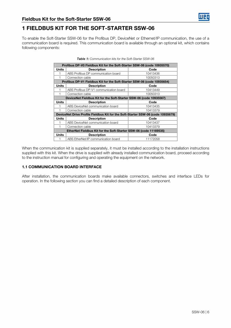
The Soft-Starter SSW-06 communication board is fitted with an automatic baud rate detection system and operates according to the configuration of the network master, thus not requiring additional configuration for this option. 2.1.2 Addressing The Profibus DP protocol allows the connection of up to 126 network devices between the masters and slaves, starting from address 0 (zero) up to address 125 (addresses 126 and127 are reserved). Each network device must have a different address. The Soft-Starter SSW-06 is fitted with two rotary switches which allow selecting the address of the Profibus DP network between 0 (zero) and 99. The drive address is formed by the composition of the values of these switches, where the left rotary switch (near the Profibus connector) indicates the decimal digit, whilst the right rotary switch (near the indication LEDs) indicates the unit digit.
Soft-Starter SSW-06 Characteristics on Fieldbus Network
SSW-06 | 8
Figure 1: Programming example of the address 15 on the Profibus DP board
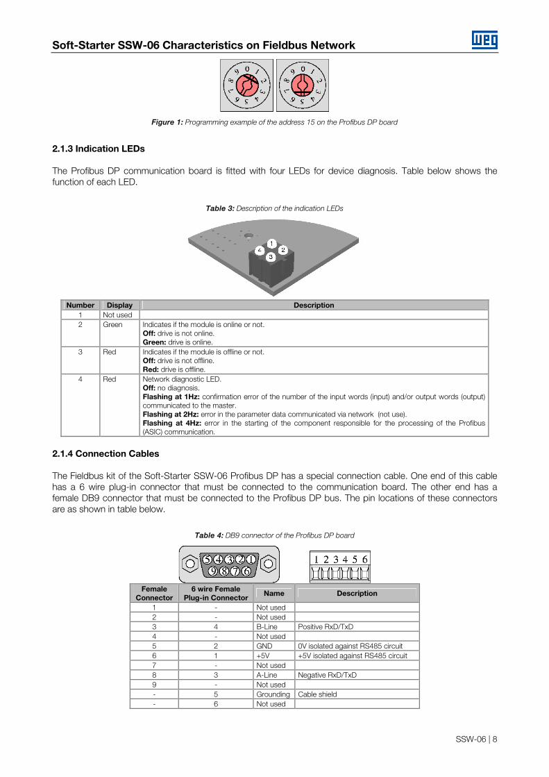
2.1.3 Indication LEDs The Profibus DP communication board is fitted with four LEDs for device diagnosis. Table below shows the function of each LED.
Table 3: Description of the indication LEDs
Number Display Description
1 Not used 2 Green Indicates if the module is online or not.
Off: drive is not online. Green: drive is online.
3 Red Indicates if the module is offline or not. Off: drive is not offline. Red: drive is offline.
4 Red Network diagnostic LED. Off: no diagnosis. Flashing at 1Hz: confirmation error of the number of the input words (input) and/or output words (output) communicated to the master. Flashing at 2Hz: error in the parameter data communicated via network (not use). Flashing at 4Hz: error in the starting of the component responsible for the processing of the Profibus (ASIC) communication.
2.1.4 Connection Cables The Fieldbus kit of the Soft-Starter SSW-06 Profibus DP has a special connection cable. One end of this cable has a 6 wire plug-in connector that must be connected to the communication board. The other end has a female DB9 connector that must be connected to the Profibus DP bus. The pin locations of these connectors are as shown in table below.
Table 4: DB9 connector of the Profibus DP board
Female
Connector 6 wire Female
Plug-in Connector Name Description
1 - Not used 2 - Not used 3 4 B-Line Positive RxD/TxD 4 - Not used 5 2 GND 0V isolated against RS485 circuit 6 1 +5V +5V isolated against RS485 circuit 7 - Not used 8 3 A-Line Negative RxD/TxD 9 - Not used - 5 Grounding Cable shield - 6 Not used
Soft-Starter SSW-06 Characteristics on Fieldbus Network
SSW-06 | 9
2.1.5 Profibus DP Cable It is recommended to perform the installation with type A cable, which characteristics are described in the Table 5: Properties of the cable Type A To ensure higher immunity against electromagnetic interferences, the cable has a pair of wires that must be twisted and shielded.
Table 5: Properties of the cable Type A
Impedance 135 a 165Ω Capacitance 30 pf/m Loop resistance 110 /km Cable diameter > 0.64 mm Cable cross section > 0.34 mm²
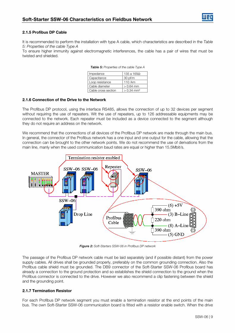
2.1.6 Connection of the Drive to the Network The Profibus DP protocol, using the interface RS485, allows the connection of up to 32 devices per segment without requiring the use of repeaters. Wit the use of repeaters, up to 126 addressable equipments may be connected to the network. Each repeater must be included as a device connected to the segment although they do not require an address on the network. We recommend that the connections of all devices of the Profibus DP network are made through the main bus. In general, the connector of the Profibus network has a one input and one output for the cable, allowing that the connection can be brought to the other network points. We do not recommend the use of derivations from the main line, manly when the used communication baud rates are equal or higher than 15.5Mbit/s.
Figure 2: Soft-Starters SSW-06 in Profibus DP network
The passage of the Profibus DP network cable must be laid separately (and if possible distant) from the power supply cables. All drives shall be grounded properly, preferably on the common grounding connection. Also the Profibus cable shield must be grounded. The DB9 connector of the Soft-Starter SSW-06 Profibus board has already a connection to the ground protection and so establishes the shield connection to the ground when the Profibus connector is connected to the drive. However we also recommend a clip fastening between the shield and the grounding point. 2.1.7 Termination Resistor For each Profibus DP network segment you must enable a termination resistor at the end points of the main bus. The own Soft-Starter SSW-06 communication board is fitted with a resistor enable switch. When the drive

Soft-Starter SSW-06 Characteristics on Fieldbus Network
SSW-06 | 10
is the first or the last element of the network, this switch must be set to Pos. “ON”. If the resistor connector has been already enabled, the termination switch of the Profibus DP network must be set to OFF. So you are able to disconnect the network element without impairing the bus, we recommend providing active terminations that will act as termination elements. In thus way you can disconnect every network drive from the bus without impairing the termination. 2.1.8 GSD File Each element of the Profibus DP network is associated to a GSD file that has all information about the element. This file describes the characteristics of each equipment and is used by the configuration program of the master of the Profibus DP network. For the Master configuration you must use the configuration file GSD supplied with the equipment. HMS Industrial Networks AB has developed the communication board used by the Soft-Starter SSW-06. Thus in the network configuration software, the product will not be recognized as a Soft-Starter SSW-06 but as "AnyBus-S PDP" in "General" category. 2.1.9 Profibus DP-V1 – Access to the Parameters The DP-V1 communication kit supports the DP-V1 services of classes 1 and 2. By using these services, besides the cyclic data exchange, it is possible to perform services of reading/writing in parameters through DP-V1 acyclic functions, by the network master, as well as by a commissioning tool. The parameter mapping is done based on the slot and index addressing, as showed in the equationing below: ■ Slot: (parameter number - 1) / 255. ■ Index: (parameter number - 1) MOD1 255. The parameter P100, for instance, will be identified through acyclic messages, as being located at slot 0, index 99. The values for the parameters are always communicated with a size of 2 bytes (1 word). The value is also transmitted as a whole number, without decimal point, and its representation depends on the used resolution.
E.g.: P003 = 3,6A value read via network = 36. 2.2 DEVICENET NETWORK The DeviceNet communication protocol has been developed in 1994 by Allen-Bradley and is currently used for linking controllers and industrial equipments, mainly for sensors, valves, starters, bar code readers, frequency inverters, operation switchgears and interfaces. There are currently several PLC, processors and communication device suppliers. One of the main DeviceNet network characteristics is the use of the CAN - Controller Area Network - for the message transmission and reception. The CAN bus comprises a twisted pair of wires that transmits a differential electrical signal responsible for sending a communication signal to all equipments connected to the same network. The DeviceNet protocol is an open protocol and you can obtain all information about its technology and so develop your own communication devices. Currently ODVA (Open DeviceNet Vendor Association - http://www.odva.org) is the company that manages the DeviceNet network specification aiming at their development. 2.2.1 Baud Rate and Soft-Starter SSW-06 Addressing The DeviceNet communication is fitted with a set of 8 switches for setting the baud rate and the Soft-Starter SSW-06 address. These switches have following functions:
1 MOD represents the remainder of the division.

Soft-Starter SSW-06 Characteristics on Fieldbus Network
SSW-06 | 11
Table 6: Baud Rate and Addressing
DIPs 3 ... 8 Address
DIPs 1 and 2 Baud rate (bit/s) 000000 0
00 125 000001 1
01 250 000010 2
10 500 ... ...
11 Reserved 111110 62
111111 63
The DeviceNet protocol defines three possible baud rates: 125, 250 and 500kbit/s. All equipments connected to the same network should be operated at the same baud rate On the Soft-Starter SSW-06, this configuration is made through the switches 1 and 2 of the communication board. One DeviceNet network device can use the addresses 0 (zero) to 63. For the Soft-Starter SSW-06 this configuration is executed through the switches 3 to 8 of the communication board. Each device on the network must have different address.
NOTE! The baud rate and the Soft-Starter SSW-06 address will be updated during the equipment start. The equipment must be switched Off/On every time configurations changes are made.
2.2.2 Indication LEDs The DeviceNet communication board is fitted with four LEDs for the device diagnosis. Table blow describes the function of each LED.
Table 7: Description of the indication LEDs
Number Indication Description
Off Power supply off / device not enabled. Green With communication between the fieldbus board and the SSW-06 soft-starter control board.
1- Host Communication Status2
Flashing red Fault in the communication between the fieldbus board and the SSW-06 soft-starter control board.
Off Bus not supplied / not online Green On Bus OK, online and connected Green flashing Online but not connected to the master Red On Critical bus fault
2 - Network status
Red flashing Timeout in the connection to the master Off Device is not being supplied/enabled Green On Operational device
3 - Module Status
Green flashing Data length longer than configured
2 Valid only for the DeviceNet Drive Profile fieldbus kit. This LED has no function for the DeviceNet fieldbus kit.
Soft-Starter SSW-06 Characteristics on Fieldbus Network
SSW-06 | 12
Red On Not recoverable fault Red flashing Recoverable fault
4 Not used
The LED 3 gives only information about the communication board and in normal status the green LED must be On continuously. The LED 2 gives information about the connection to the network and informs if the device is communicating to the masters or not. In normal status, this green LED must be On continuously. Changes on this LED may be caused due to connection problems with the bus or configuration problems with the network master. 2.2.3 DeviceNet Connector and Network Cable The Fieldbus kit for the DeviceNet of the Soft-Starter SSW-06 has a female 5 wire plug-in connector that must be used for the bus connection. The connector pin location, as well as the used standard colors of the DeviceNet cable, is shown in table below.
Table 8: Connector for the DeviceNet Network
Pin Name Color 1 V- Black 2 CAN_L Blue 3 Shield 4 CAN_H White 5 V+ Red
For the connection of the several equipments to the network, we recommend using a shielded cable with two pairs of twisted wire: one pair for the communication signal transmission (CAN_L and CAN_H) and the other pair of twisted wire for the supply signal (V- and V+). The maximum allowed cable length depends on the communication baud rate and on the used cable type. Table below shows the relation between the used communication rate and the maximum allowed cable length.
Table 9: Maximum length of the DeviceNet cable
Communication baud rate 125 Kbit/s 250 Kbit/s 500 Kbit/s
Thick Cable 500 m 250 m 100 m Fine cable 100 m 100 m 100 m Maximum length per cable derivation 6 m 6 m 6 m C
able
T
ype
Accumulated maximum length of the derivations 156 m 78 m 39 m
2.2.4 Bus Supply As already informed above, one of the DeviceNet network characteristics is the network cable that must be formed by one pair of twisted wires to send the voltage supply to all devices connected to the bus. This voltage is used to supply the interface circuit with the network. Table below shows the current and voltage data of the power supply for the Soft-Starter SSW-06 communication board.
Supply voltage (Vdc) Minimum Maximum Recommended 11 25 24
Current consumption (mA) Minimum Maximum Typical - 30 25
Soft-Starter SSW-06 Characteristics on Fieldbus Network
SSW-06 | 13
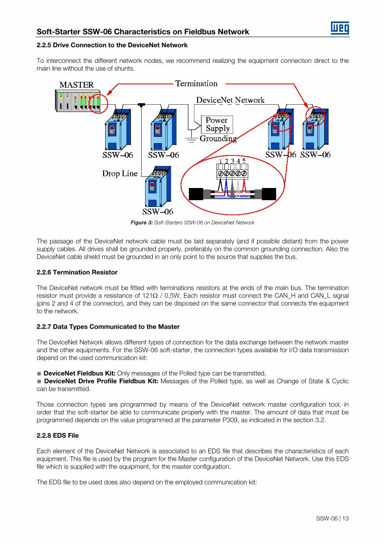
2.2.5 Drive Connection to the DeviceNet Network To interconnect the different network nodes, we recommend realizing the equipment connection direct to the main line without the use of shunts.
Figure 3: Soft-Starters SSW-06 on DeviceNet Network
The passage of the DeviceNet network cable must be laid separately (and if possible distant) from the power supply cables. All drives shall be grounded properly, preferably on the common grounding connection. Also the DeviceNet cable shield must be grounded in an only point to the source that supplies the bus. 2.2.6 Termination Resistor The DeviceNet network must be fitted with terminations resistors at the ends of the main bus. The termination resistor must provide a resistance of 121Ω / 0,5W. Each resistor must connect the CAN_H and CAN_L signal (pins 2 and 4 of the connector), and they can be disposed on the same connector that connects the equipment to the network. 2.2.7 Data Types Communicated to the Master The DeviceNet Network allows different types of connection for the data exchange between the network master and the other equipments. For the SSW-06 soft-starter, the connection types available for I/O data transmission depend on the used communication kit: ■ DeviceNet Fieldbus Kit: Only messages of the Polled type can be transmitted. ■ DeviceNet Drive Profile Fieldbus Kit: Messages of the Polled type, as well as Change of State & Cyclic can be transmitted. Those connection types are programmed by means of the DeviceNet network master configuration tool, in order that the soft-starter be able to communicate properly with the master. The amount of data that must be programmed depends on the value programmed at the parameter P309, as indicated in the section 3.2. 2.2.8 EDS File Each element of the DeviceNet Network is associated to an EDS file that describes the characteristics of each equipment. This file is used by the program for the Master configuration of the DeviceNet Network. Use this EDS file which is supplied with the equipment, for the master configuration. The EDS file to be used does also depend on the employed communication kit:
Soft-Starter SSW-06 Characteristics on Fieldbus Network
SSW-06 | 14
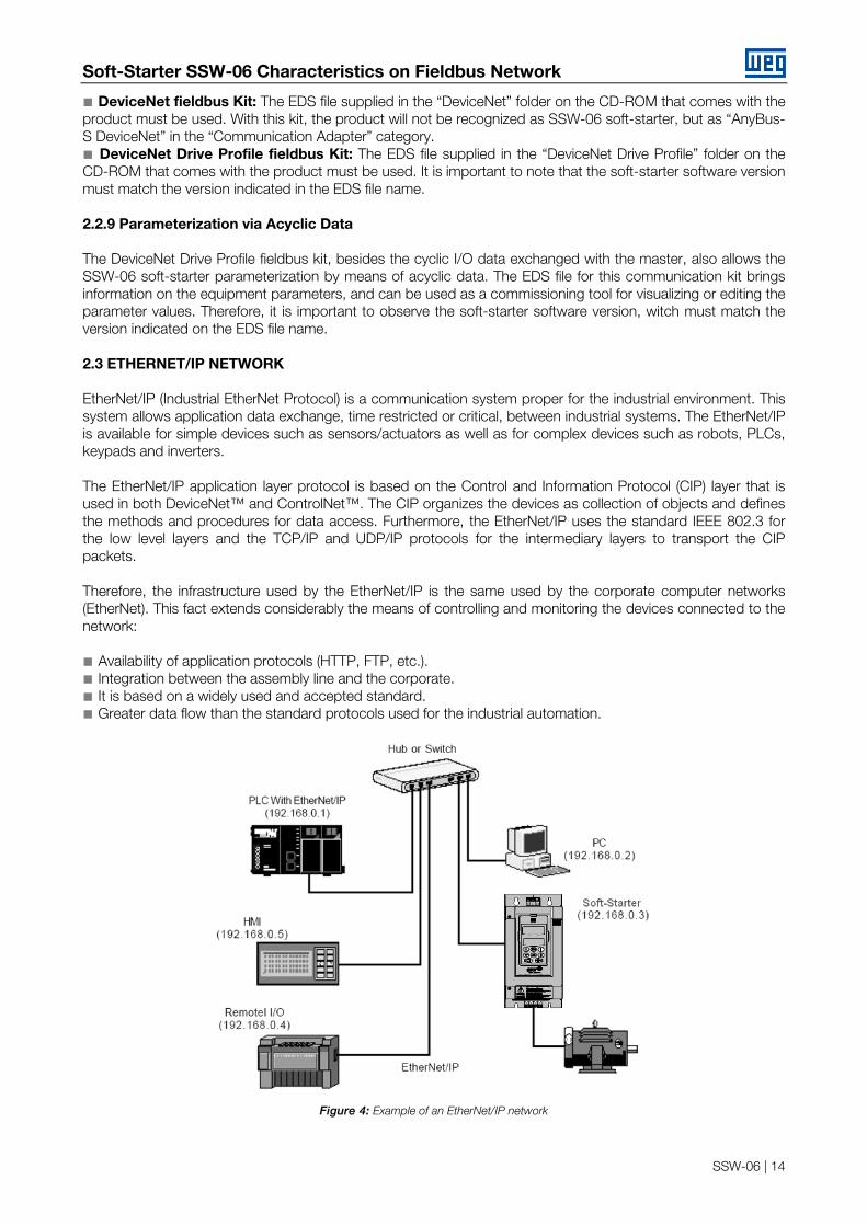
■ DeviceNet fieldbus Kit: The EDS file supplied in the “DeviceNet” folder on the CD-ROM that comes with the product must be used. With this kit, the product will not be recognized as SSW-06 soft-starter, but as “AnyBus-S DeviceNet” in the “Communication Adapter” category. ■ DeviceNet Drive Profile fieldbus Kit: The EDS file supplied in the “DeviceNet Drive Profile” folder on the CD-ROM that comes with the product must be used. It is important to note that the soft-starter software version must match the version indicated in the EDS file name. 2.2.9 Parameterization via Acyclic Data The DeviceNet Drive Profile fieldbus kit, besides the cyclic I/O data exchanged with the master, also allows the SSW-06 soft-starter parameterization by means of acyclic data. The EDS file for this communication kit brings information on the equipment parameters, and can be used as a commissioning tool for visualizing or editing the parameter values. Therefore, it is important to observe the soft-starter software version, witch must match the version indicated on the EDS file name. 2.3 ETHERNET/IP NETWORK EtherNet/IP (Industrial EtherNet Protocol) is a communication system proper for the industrial environment. This system allows application data exchange, time restricted or critical, between industrial systems. The EtherNet/IP is available for simple devices such as sensors/actuators as well as for complex devices such as robots, PLCs, keypads and inverters. The EtherNet/IP application layer protocol is based on the Control and Information Protocol (CIP) layer that is used in both DeviceNet™ and ControlNet™. The CIP organizes the devices as collection of objects and defines the methods and procedures for data access. Furthermore, the EtherNet/IP uses the standard IEEE 802.3 for the low level layers and the TCP/IP and UDP/IP protocols for the intermediary layers to transport the CIP packets. Therefore, the infrastructure used by the EtherNet/IP is the same used by the corporate computer networks (EtherNet). This fact extends considerably the means of controlling and monitoring the devices connected to the network: ■ Availability of application protocols (HTTP, FTP, etc.). ■ Integration between the assembly line and the corporate. ■ It is based on a widely used and accepted standard. ■ Greater data flow than the standard protocols used for the industrial automation.
Figure 4: Example of an EtherNet/IP network

Soft-Starter SSW-06 Characteristics on Fieldbus Network
SSW-06 | 15
2.3.1 Fieldbus Connector Connector: RJ-45 connector with 8-pin. Pinout: two standards for straight-through cables are available: EtherNet: T-568A and T-568B. The function of each pin is shown in Figure 5. The cable to be used with the Soft-Starter SSW-06 shall follow one of these two standards. Furthermore, only one standard shall be used for the cables, i.e., the connectors of both cable ends shall be crimped according to standard T-568Aor T-568B. a) RJ-45 Plug - T-568A Standard
Pin Cable Color Signal 1 White/Green TX+ 2 Green TX- 3 White/Orange RX+ 4 Blue - 5 White/Blue - 6 Orange RX- 7 White/Brown - 8 Brown -
b) RJ-45 Plug - T-568B Standard
Pin Cable Color Signal 1 White/Orange TX+ 2 Orange TX- 3 White/Green RX+ 4 Blue - 5 White/Blue - 6 Green RX- 7 White/Brown - 8 Brown -
Figure 5 a) and b): Straight-Through EtherNet cables
2.3.2 Line Termination With the EtherNet 10BASE-T (10Mbps) or 100BASE-TX (100Mbps) the line termination is already on the communication board and also on any other device that uses a point-to-point twisted pair cable. Therefore, no additional setting is needed for the Soft-Starter SSW-06. 2.3.3 Communication Bit-rate The Soft-Starter SSW-06 can operate in an EtherNet network at 10Mbps or 100Mbps and also in half-duplex or full-duplex modes. When operating at 100Mbps in full-duplex mode, the effective rate doubles to 200Mbps. These configurations are performed through the network configuration and programming software. No board setting is needed. It is recommended to use the auto-sensing resource. 2.3.4 Configuration File (EDS File) Each device on an EtherNet/IP network is associated to an EDS file that contains information about the device operation. The EDS file provided along with the product is used by the network configuration software. 2.3.5 Configuration of the Network Master Data For the master configuration, besides the IP address used by the EtherNet/IP board, it is necessary to indicate the number of I/O instances and the quantity of data exchanged with the master in each instance. For the Soft-Starter SSW-06 with Anybus-S EtherNet/IP board, the following values must be programmed: ■ Input Instance: 100

Soft-Starter SSW-06 Characteristics on Fieldbus Network
SSW-06 | 16
■ Output Instance: 150 ■ Data amount programmable through P309: it may be 1, 4 or 7 words with 16 bits (2, 8 or 14 bytes). ■ The EtherNet/IP board for the Soft-Starter SSW-06 is described in the network as a Generic Ethernet Module. By using these configurations it is possible to program the network master so that it communicates with the Soft-Starter SSW-06. 2.3.6 Indication The communication board has four two-color LEDs located on the right bottom corner to indicate the module and the network status.
Figure 6: Indication LEDs for the status of the EtherNet/IP network
LED Color Function
Link Green On: the module is connected to another device on the network (typically a hub or switch). Off: the module is not connected to another device.
Module Status Green or Red Steady Off: No power applied o the module. Steady Green: The module is operating correctly. Flashing Green: the module has not been configured, or network master in IDLE. Flashing Red: A minor recoverable error has been detected. Steady Red: A major internal error has been detected. Flashing Green/Red: The module is performing a power on self-test.
Network Status Green or Red Steady Off: The module has no power or no IP address has been assigned. Steady On: the module has at least one established EtherNet/IP connection. Flashing Green: There are no EtherNet/IP connections established to the module. Flashing Red: One or more of the connections in which this module is the target has timed out. Steady Red: The module has detected that its IP address is already in use. Flashing Green/Red: The module is performing a power on self-test.
Activity Green Flashing: indicates that a packet has been received and/or transmitted.
NOTE! The communication board that comes with the product has been developed by the HMS Industrial Networks AB Company. Therefore, the network configuration software will not recognize the product as the Soft-Starter SSW-06, but as the “Anybus-S EtherNet/IP” at the “Communication Adapter”. The differentiation among several Soft-Starter SSW-06 will be based on the device address on the network.
2.3.7 Control and Monitoring Through the WEB
The EtherNet/IP communication board has an HTTP server internally. This means that the communication board can serve HTML pages. In such a way, it is possible to configure network parameters, control, and monitor the Soft-Starter SSW-06 through a WEB browser installed in a computer connected to the same network of the Soft-Starter. Use the same read/write variables of the Soft-Starter to perform these operations (refer to chapter 4).
NOTE! For the first WEB access use the factory default username and password. Username: web Password: web.

Soft-Starter SSW-06 Characteristics on Fieldbus Network
SSW-06 | 17
Figure 7: Open window when accessing the Soft-Starter SSW-06 through the WEB
Figure 8: Control and monitoring window when accessing the Soft-Starter SSW-06 through the WEB
NOTE! It is necessary to have a PC with an EtherNet card connected to the same network of the Soft-Starter SSW-06 and a WEB browser (MS Internet Explorer or Mozilla/Firefox.
2.3.8 Configurations Follow the steps below to operate the Soft-Starter SSW-06 in an EtherNet/IP network. 1) Install the KFB-EN kit into the Soft-Starter SSW-06. 2) At parameter P309 select the EtherNet/IP protocol and the number of input/output words, P309 = 7, 8 or 9.

Soft-Starter SSW-06 Characteristics on Fieldbus Network
SSW-06 | 18
3) Connect the RJ-45 plug of the EtherNet cable to the Soft-Starter SSW-06 and make sure that the Link LED is ON (LED 1). 4) Open your WEB browser and type the Soft-Starter SSW-06 address on the network. The factory default value is ‘http://192.168.0.1’. Make sure that JavaScript and cookies are enabled in the WEB browser. The data access is protected by username and password. The Soft-Starter SSW-06 has the following factory default values: Username: web and Password: web.
5) At the ‘Configuration’ tab of the WEB page shown in figure X set, if needed, the ‘Network Parameters’. 5.1) If the Soft-Starter SSW-06 address on the network belongs to the reserved range ‘192.168.0.X’, it is possible to use the DIP-switches of the communication board for addressing purposes. In this case, the DIP-switch represents the binary value of the last byte in the IP address. Example:
The DIP-switch is set to 00010100 (20 in decimal format). Thus, the Soft-Starter SSW-06 address on the network is 192.168.0.20. 5.2) If the Soft-Starter SSW-06 has an IP address out of the default range (192.168.0.X), deactivate the hardware addressing by setting the DIP-switches to zero (00000000). 5.3) If the network addressing is performed through a DHCP server, select the box ‘DHCP enabled’ and set the DIP-switches to zero (00000000). 5.4) Click on the button ‘STORE CONFIGURATION’ to save the new settings.
Soft-Starter SSW-06 Characteristics on Fieldbus Network
SSW-06 | 19
6) Adjust also the content of the parameter P309. 7) Adjust the Online/Offline configuration: 7.1) In order that the Online/Offline status change be done when a change in the link status occurs, select the ‘Link’ option. 7.2) In order that the Online/Offline status change be done when no telegrams are being exchanged with the EtherNet/IP master, select the ‘EtherNet/IP’ option. 7.3) In order that the Online/Offline status change be done when no telegrams at the SSW-06 are being exchanged with the Modbus Master for a certain period of time, select the ‘Modbus’ option and adjust the Timeout according to the application. 7.4) Click on the ‘STORECONFIGURATION’ button to save the configurations. Restart the Soft-Starter SSW-06. 2.3.9 Access to the Communication Board The communication board supports FTP and Telnet services. In such a way, it is possible to upload/download files to/from the board and also access the file system in an interactive way. In order to use these services follow the instructions below: ■ Open a MS-DOS command window. ■ Type the desired service (FTP or Telnet) followed by the IP address or hostname of the Soft-Starter SSW-06 on the network. ■ Enter with: Login: user Password: user 2.3.10 Examples Telnet session for the Soft-Starter SSW-06 with IP address 192.168.0.1.
Soft-Starter SSW-06 Characteristics on Fieldbus Network
SSW-06 | 20
FTP session for the Soft-Starter SSW-06 whit IP address 192.168.0.1.
2.3.11 Security and Access Passwords The file system of the communication board has two security levels for the user: admin and normal. It is only permitted to connect in the normal mode. In this case, the users are restricted to the directory ‘user\’, where it is possible to create or delete files and/or folders. The accounts for normal users are defined in the file ‘sys_pswd.cfg’ that is located under directory ‘user\pswd\’. Each line of the file has a pair ‘login:password’ that corresponds to a user account. In order to change the file containing the user accounts, create, with the assistance of a simple text editor, a file that contains in each line a pair ‘login:password’. A colon shall separate the two words. Notice that no password cryptography is available, i.e., the login and the password are completely visible. After creating/modifying the user accounts, transfer via FTP the file ‘sys_pswd.cfg’ to the directory ‘user\pswd\’. Example of file transfer through FTP:

Soft-Starter SSW-06 Characteristics on Fieldbus Network
SSW-06 | 21
NOTE! The Soft-Starter SSW-06 that comes from the factory has a normal user account: Username: user Password: user Users of the normal security level are restricted to the directory ‘\user’.
In addition to the access control for the file system, there is also an Access control for the HTML pages of the communication board. The file containing the access passwords is located under the directory ‘user\pswd’, and it is named ‘web_accs.cfg’. As in the previous case, each line of the ‘web_accs.cfg’ file represents an access account. In order to change the user accounts for the HTML pages, create a text file with the same name (‘web_accs.cfg’) and insert in each line of this file a pair ‘login:password’ for the users with access permission. After that, transfer this new file through FTP to the communication board, exactly as in the previous case.
NOTE! It is strongly recommended to change all passwords of the EtherNet/IP communication board after the start-up of the device. The new passwords will be effective only after powering down and up the Soft-Starter SSW-06.
NOTE! When the Soft-Starter SSW-06 returns from the off-line state the output values are reset.
2.4 THE MODBUS/TCP NETWORK Modbus is a data communication protocol used in industrial automation systems. Created in the 1970’s by Modicon, it is one of the oldest protocols used in automation equipment supervision and control networks. The Modbus/TCP protocol is an implementation of the Modbus standard over TCP/IP, making it possible the use of a Modbus message system in an ‘Intranet’ or ‘Internet’ network. Modbus/TCP basically encapsulates in a simple manner a Modbus frame into a TCP frame. Modbus/TCP uses the Ethernet (IEEE 802.3) physical layer and a client-server model. The used infrastructure is the same already used by corporative Ethernet computer networks. This fact increases considerably the control and monitoring possibilities for equipments connected in networks. The SSW-06 EtherNet/IP board has a Modbus/TCP server that makes available the access to Input and Output areas by means of a set of functions defined in the Modbus/TCP specification. All the messages use the TCP 502 port and the Modbus/TCP is able to manage a maximum of 8 simultaneous connections. The following Modbus/TCP protocol topics are similar to the ones described for the EtherNet/IP protocol:
Description: Refer to section:
Fieldbus Connector 2.3.1 Line Termination 2.3.2

Soft-Starter SSW-06 Characteristics on Fieldbus Network
SSW-06 | 22
Baud Rate 2.3.3 Indications 2.3.6
Control and Monitoring Through the WEB 2.3.7 Configurations 2.3.8
Access to the Communication Board 2.3.9
2.4.1 Network Master Data Configuration In order to use the Modbus/TCP protocol of the EtherNet/IP communication board, it is necessary to configure the amount of data exchanged with the master. For the SSW-06 soft-starter with EtherNet/IP Anybus-S board, the amount of data is programmed through P309, and can be 1, 4 or 7 words with 16 bits (2, 8 or 14 bytes). The I/O word mapping in the Modbus protocol is presented in the table below:
Table 1: Addressing Map
Area Register Coil I/O word 1 1... 16 1st word 2 17... 32 2nd word 3 33... 48 3rd word 4 49... 64 4th word 5 65... 80 5th word 6 81... 96 6th word
Input Data
7 97... 112 7th word 1025 16385... 16400 1st word 1026 16401... 16416 2nd word 1027 16417... 16432 3rd word 1028 16433... 16448 4th word 1029 16449... 16464 5th word 1030 16465... 16480 6th word
Output Data
1031 16481... 16496 7th word
NOTES! The table above applies to all the function codes. Coils are mapped with the MSB first, i.e., coil #1 corresponds the bit 15 of the register #1. I/O words are represented in the registers with the least significant byte first. Thus, it may be necessary to swap the most significant byte with the least significant, so that the words be correctly interpreted by the network master.
Several Modbus functions can be used to access the same data area in the module. The functions available for the EtherNet/IP module are presented below:
Table 2: Codes of Supported Functions
Modbus Function Function Code Associated with... Read Coil 1 Read Input Discrete 2 Read Multiple Registers 3 Read Input Registers 4
Input and Output data
Write Coil 5 Write Single Register 6 Force Multiple Coils 15 Force Multiple Registers 16 Mask Write Register 22
Output data
Read/Write Registers 23 Input and Output data
Table 3: Supported Error Codes
Code Name Description 0x01 Illegal function Not supported function code 0x02 Illegal data address Address outside of the initialized memory area 0x03 Illegal data value Illegal value
Fieldbus Communication Parameters
SSW-06 | 23
3 FIELDBUS COMMUNICATION PARAMETERS The Soft-Starter SSW-06 has a set of parameters, described below, that are used for the network device configuration. All other parameter that are not described in this section do not have direct relation with this function, however these parameters are important for the equipment operation. Thus you must know how to use the equipment via parameters, since they can be used also during the operation via network. For complete parameter listing and their respective description, please refer to the Soft-Starter SSW-06 Manual. 3.1 P085 – STATUS OF THE FIELDBUS BOARD This read parameter indicates the status of the communication board. This parameter can be set to:
Range Standard Access 0 = Disable 1 = Board inactive 2 = Offline 3 = Online 4 = Profibus Stop
- Read-only
■ 0 – Disable: indicates that the board has not been enabled. The board enable is executed through the parameter P309. ■ 1 – Board inactive: indicates that the board has been enabled through the parameter P309, however the Soft-Starter could not access the board correctly, or the programmed network is different from the used board. This problem can occur mainly during the board start-up due to bad contacts or installation faults. When the board becomes inactive, the fault message 30 is displayed on the product HMI and the communication board can only be enabled again when the Soft-Starter SSW-06 is reset. ■ 2 – Board active and offline: indicates a communication fault between the board Fieldbus and the network master. This fault can occurs due to several reasons (master configuration fault, communication cables were not installed correctly, high noise level during the data transfer, etc.) and do not allow the communication between the drive and the master. Always the board Fieldbus passes to the status offline, a fault message will be displayed on the Soft-Starter SSW-06 HMI. ■ 3 – Board active and online: indicates that the communication between the Soft-Starter SSW-06 and the master is being executed with success. ■ 4 – Profibus stop: indicates that the network master is stopped.
NOTE! For the DeviceNet network, when the network master is in Idle status, this condition will be considered as a communication fault. The board remains in offline status and the fault message 29 is displayed in the HMI.
3.2 P309 – FIELDBUS BOARD ENABLE This parameter allows the Fieldbus board enable and programming the number of words to be communicated between the Soft-Starter SSW-06 and the network master.
Range Standard Access 0 = Disabled 1 = Profibus DP 1 I/O 2 = Profibus DP 4 I/O 3 = Profibus DP 7 I/O 4 = DeviceNet 1 I/O 5 = DeviceNet 4 I/O 6 = DeviceNet 7 I/O 7 = EtherNet/IP 1 I/O 8 = EtherNet/IP 4 I/O 9 = EtherNet/IP 7 I/O
0 Read/write
Fieldbus Communication Parameters
SSW-06 | 24
For the communication, three different options can be selected, containing 1, 4 or 7 input / output words (1, 4 or 7 words, where 1 word = 2 bytes). Section 4 describes the content of each word.
NOTES! ■ If this parameter is changed in order to accept new configurations, the Soft-Starter SSW-06 will execute its reset automatically. ■ During the Soft-Starter SSW-06 updating and if the board was not programmed, a start-up message for the Fieldbus board will be displayed. The equipment can only be operated again after the start-up process has been concluded.
3.3 P310 – DETECTION OF STOPPED PROFIBUS MASTER By means of the command word bit 6, Item 4.3, it is possible to detect that the master is stopped. In order that this protection works correctly, the bit 6 of the soft-starter SSW-06 command word must remain in 1 and the parameter P310 also in 1.
Range Standard Access 0 = Inactive 1 = Active
0 Read/write
3.4 P313 – CORRECTIVE ACTIONS IN CASE OF COMMUNICATION ERROR When the drive is being controlled via network, and a communication error to the master is detected (cable rupture, voltage drop, master fault, etc.), you cannot send an equipment disable command via serial communication. In applications where this is a problem, you can program an action at P313 that the Soft-Starter SSW-06 will execute automatically in case of network fault.
Range Standard Access 0 = Not used 1 = Disable 2 = General disable 3 = Changes to Local 4 = Not used 5 = Fatal error
0 Read/write
For the Fieldbus communication will be considered communication errors the errors 29 (offline board or Master in Idle) and error 30 (board inactive). ■ 0 – No action: when some of the above mentioned errors occur, the drive remains in the current status and only displays the occurred error. ■ 1 – Disable: in case of communication error, the Soft-Starter SSW-06 will be disabled via voltage ramp. ■ 2 – General disable: in this option, the Soft-Starter SSW-06 interrupts the motor power supply and the motor stop by inertia. ■ 3 – Change to local: when the switch is operating in remote mode and a communication error is detected, it changes automatically to local mode. ■ 4 – Not used: the same action of the 0 option. ■ 5 – Cause fatal error: when detecting imperfection in the communication the Soft-Starter SSW-06 will go for the error state, the motor will be disabled and the indication of error will only be removed after to reset the error of the equipment.

Fieldbus Communication Parameters
SSW-06 | 25
NOTES! ■ The disable command and the command for changing to local mode can only be executed by the switch when they are controlled via Fieldbus. This programming is executed through the parameters P220, P229 e P230. ■ Independent of the value set in this parameter, when some digital and/or analog output is being controlled via Fieldbus, theses outputs will be reset when some communication error is detected.
3.5 P315 – FIELDBUS #1 READ PARAMETER This parameter allows selecting the number of another parameter, which content will be available in the second word of the input area (data sent from the Soft-Starter SSW-06 to the network master) for the Fieldbus communication. For programming correctly the read parameters via network, you must know the Soft-Starter SSW-06 parameters and define which information should be read by the network master.
Range Standard Access 0 ... 999 0 Read/write
For example, if you want to read the motor current in Amperes from the Soft-Starter SSW-06, you must program in this parameter the value 3, since the parameter P003 is the parameter that contains this information. Please consider that the read value of any parameter is represented by a 16 bits word with signal, as supplement of 2. Although the parameter has a decimal resolution, the value will be transmitted without the indication of decimal places. For instance, if the parameter P003 has the value 4.7 A, the supplied value via network will be 47. This word will be only active, when 4 or 7 input / output words are programmed in P309. If you don’t use this word, the master must ignore the received word. If a number of a no existent parameter is programmed, the value sent by the Soft-Starter SSW-06 will be always 0 (zero). 3.6 P316 – FIELDBUS #2 READ PARAMETER This parameter is similar to the parameter P315. This parameter allows programming the third read word of the input area. It will be only active when 4 or 7 input / output words are programmed in P309. 3.7 P317 – FIELDBUS #3 READ PARAMETER This parameter is similar to the parameter P315. This parameter allows programming the fourth read word of the input area. It will be only active when 4 or 7 input / output words are programmed in P309. 3.8 P220 – LOCAL/REMOTE SOURCE SELECTION This parameter allows programming the command source that controls the equipment local/remote mode.
Range Standard value Access 0 = Always local 1 = Always remote 2 = Keypad (local as standard) 3 = Keypad (remote as standard) 4 = DI4...DI5 5 = Serial (local as standard) 6 = Serial (remote as standard) 7 = Fieldbus (local as standard) 8 = Fieldbus (remote as standard) 9 = SoftPLC (local as standard) 10 = SoftPLC (remote as standard)
2 Read/write
If you want to control the operation mode via Fieldbus, you must program this parameter to 7 or 8. The display “local as standard” or “remote as standard” informs the operation mode must be activated after equipment start.
Fieldbus Communication Parameters
SSW-06 | 26
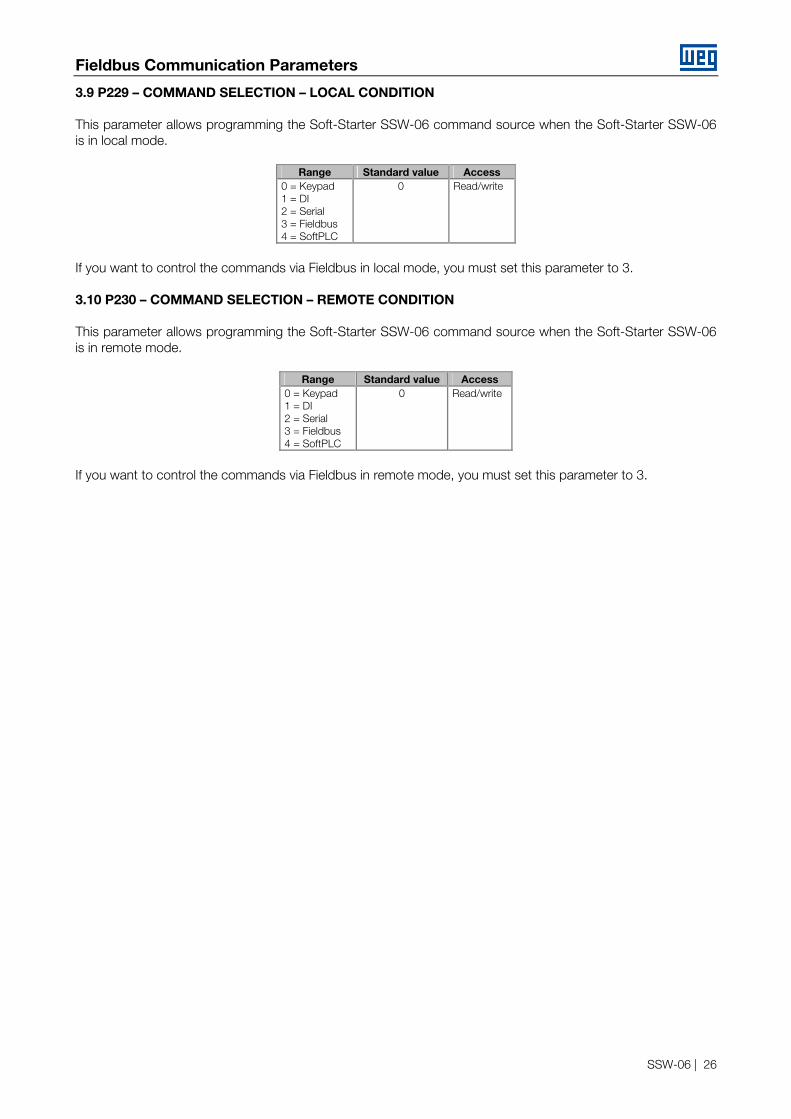
3.9 P229 – COMMAND SELECTION – LOCAL CONDITION This parameter allows programming the Soft-Starter SSW-06 command source when the Soft-Starter SSW-06 is in local mode.
Range Standard value Access 0 = Keypad 1 = DI 2 = Serial 3 = Fieldbus 4 = SoftPLC
0 Read/write
If you want to control the commands via Fieldbus in local mode, you must set this parameter to 3. 3.10 P230 – COMMAND SELECTION – REMOTE CONDITION This parameter allows programming the Soft-Starter SSW-06 command source when the Soft-Starter SSW-06 is in remote mode.
Range Standard value Access 0 = Keypad 1 = DI 2 = Serial 3 = Fieldbus 4 = SoftPLC
0 Read/write
If you want to control the commands via Fieldbus in remote mode, you must set this parameter to 3.

Operation via Network
SSW-06 | 27
4 OPERATION VIA NETWORK As already described in item 3, the parameter P309 allows programming the number of the I/O words (words3) that will be exchanged with the master. This item shows the data format for each existing options. 4.1 CONTENT OF THE I/O WORDS Depending on the value selected at parameter P309, the drive will communicate to the network master 1, 4 or 7 I/O output words. The higher the number of words communicated via network, the higher will be the available functions for the Soft-Starter SSW-06 operation and the larger will be the reserved memory in the master and the time required for the communication. Table below shows the content of each input and output word for the different options:
Table 10: I/O Data Format
Input (drive -> master) Output (master -> drive) SSW-06 Status 1st word Command for the SSW-06 1 I/O Read parameter #1 2nd word Value for the digital outputs Read parameter #2 3rd word Value for the analog output AO1 Read parameter #3 4th word Value for the analog output AO2
4 I/O
Response to the read/write commands in parameters
5th word 6th word 7th word
Command sending for read/write in parameters
7 I/O
4.1.1 One I/O Word (P309 = 1, 4 or 7) When an I/O word is selected, the drive will communicate to the master only the first input an output words, described in Table 10, that represent the status and the command word of the Soft-Starter SSW-06. This is the easiest operation mode, suitable for the command and monitoring operations that do not require a large number of data to be transmitted between the drives. 4.1.2 Four I/O Words (P309 = 2, 5 or 8) When four I/O words are selected, the drive will communicate to the master only the first input an output words, described in Table 10, that represent the status and the command word of the Soft-Starter SSW-06, in addition to the three programmable parameters for the read/write process. This operation mode allows the transfer of a higher number of data between the master and the slave, allowing reading a higher number of parameters in addition to the digital and the analog command of the switch. 4.1.3 Seven I/O Word (P309 = 3, 6 or 9) When seven I/O words are selected, the drive will communicate to the master all the input and output words, described in Table 10. This allows the communication of the status and the command word, three programmable read parameters, the digital and the analog output command, in addition to the digital and the analog command of the switch. This operation mode permits the complete drive parameter setting. 4.2 STATUS WORD This word is transmitted from the Soft-Starter SSW-06 to the network master, in the first position of the input data, supplying several information about the drive status. This word comprises 16 bits and has following function:
3 One word is equal to two bytes.
Operation via Network
SSW-06 | 28
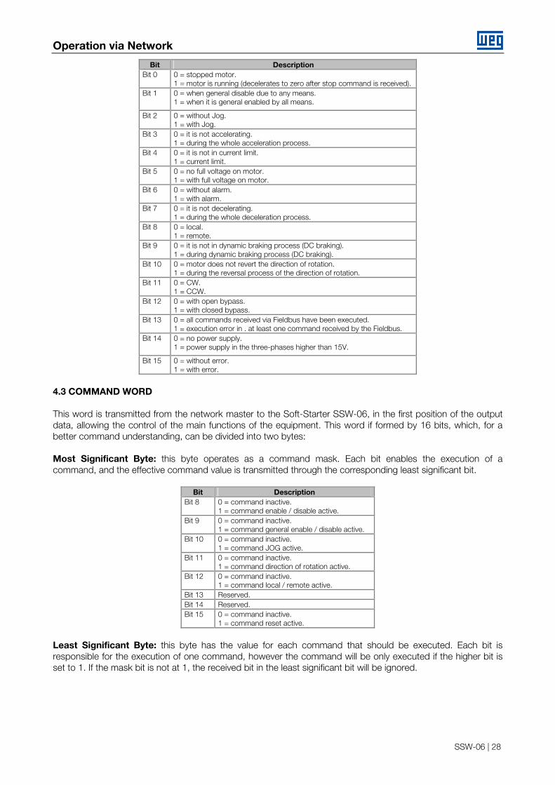
Bit Description Bit 0 0 = stopped motor.
1 = motor is running (decelerates to zero after stop command is received). Bit 1 0 = when general disable due to any means.
1 = when it is general enabled by all means.
Bit 2 0 = without Jog. 1 = with Jog.
Bit 3 0 = it is not accelerating. 1 = during the whole acceleration process.
Bit 4 0 = it is not in current limit. 1 = current limit.
Bit 5 0 = no full voltage on motor. 1 = with full voltage on motor.
Bit 6 0 = without alarm. 1 = with alarm.
Bit 7 0 = it is not decelerating. 1 = during the whole deceleration process.
Bit 8 0 = local. 1 = remote.
Bit 9 0 = it is not in dynamic braking process (DC braking). 1 = during dynamic braking process (DC braking).
Bit 10 0 = motor does not revert the direction of rotation. 1 = during the reversal process of the direction of rotation.
Bit 11 0 = CW. 1 = CCW.
Bit 12 0 = with open bypass. 1 = with closed bypass.
Bit 13 0 = all commands received via Fieldbus have been executed. 1 = execution error in . at least one command received by the Fieldbus.
Bit 14 0 = no power supply. 1 = power supply in the three-phases higher than 15V.
Bit 15 0 = without error. 1 = with error.
4.3 COMMAND WORD This word is transmitted from the network master to the Soft-Starter SSW-06, in the first position of the output data, allowing the control of the main functions of the equipment. This word if formed by 16 bits, which, for a better command understanding, can be divided into two bytes: Most Significant Byte: this byte operates as a command mask. Each bit enables the execution of a command, and the effective command value is transmitted through the corresponding least significant bit.
Bit Description Bit 8 0 = command inactive.
1 = command enable / disable active. Bit 9 0 = command inactive.
1 = command general enable / disable active. Bit 10 0 = command inactive.
1 = command JOG active. Bit 11 0 = command inactive.
1 = command direction of rotation active. Bit 12 0 = command inactive.
1 = command local / remote active. Bit 13 Reserved. Bit 14 Reserved. Bit 15 0 = command inactive.
1 = command reset active.
Least Significant Byte: this byte has the value for each command that should be executed. Each bit is responsible for the execution of one command, however the command will be only executed if the higher bit is set to 1. If the mask bit is not at 1, the received bit in the least significant bit will be ignored.

Operation via Network
SSW-06 | 29
Bit Description Bit 0 0 = stopping by ramp.
1 = running by ramp. Bit 1 0 = general disable.
1 = general enable. Bit 2 0 = without JOG.
1 = with JOG. Bit 3 0 = CW.
1 = CWW. Bit 4 0 = local.
1 = remote. Bit 5 Reserved. Bit 6 Profibus Master Stop Detection:
0 = Stop. 1 = Running.
Bit 7 0 = no command. 0 → 1 = executes reset (if in error status).
Always a command is sent to the Soft-Starter SSW-06, it will only accept and execute the command when it has been programmed to receive commands via Fieldbus. This programming is executed through the following parameters: ■ P220 - Local / remote source selection. ■ P229 - Command selection in local mode. ■ P230 - Command selection in remote mode. These commands must be programmed to the "Fieldbus" option always you want to execute the respective command via network. The reset command can be executed via network, even without this parameter setting, but the reset command can be executed only when the Soft-Starter SSW-06 is in error status.
NOTES! ■ Errors of the communication board (E28, E29 or E30) can not be reset in this way, since they depend on settings outside the values sent via network to be solved and also why the drive is this condition is unable to communicate the network. ■ If you try to execute a command via network, but this command cannot be executed by Soft-Starter SSW-06 (for instance a command that was not programmed to operate via Fieldbus), this command will not be executed and the value 1 will be indicated in the bit 13 of the status word.
4.4 READ PARAMETER #1 ... #3 Depending on the number of I/O words that have been configured for the communication, you can program the reading of 3 drive parameters. This programming is made in the parameters P315 to P317, as explained in item 3. So you can associate the content of one parameter directly to the input area that is communicated to the master, thus enabling the read of this parameter via network. The content of these parameters is read from the 2nd input word on, as shown in item 4.1 (read parameter #1, #2 and #3). This enables reading the parameters which content is useful for the drive operation via network. For instance: ■ P002 = motor current in % of the rated motor current. ■ P003 = motor current in amperes. ■ P007 = output voltage. ■ P014 = last occurred error, etc. The read value of any parameter is represented by a 16 bits word with signal, as supplement of 2. Even when the parameter has a decimal resolution, the value will be transmitted without indication of the decimal places. For instance, if the parameter P003 (motor current) has the value 4.7 A, the value transmitted via network will be 47.
Operation via Network
SSW-06 | 30
NOTE! In the models of 820A and above, all the parameters related to the current (A) and power (kW and kVA) indication are divided by ten: P003, P010, P011, P030, P031, P032, P047, P048, P053, P060, P063, P066, P069, P072, P075.
4.5 COMMAND FOR THE DIGITAL OUTPUTS If 4 or 7 I/O words are programmed for the Soft-Starter SSW-06, you can control the digital outputs of the drive through the second output word. This word is formed by 16 bits, where only the first three bits have a function:
Bit Description Bit 0 0 = deactivates the RL1 relay output.
1 = activates the RL1 relay output. Bit 1 0 = deactivates the RL2 relay output.
1 = activates the RL2 relay output. Bit 2 0 = deactivates the RL3 relay output.
1 = activates the RL3 relay output. Bit 3 ... 15 Reserved.
To command the digital outputs via network, you must program is functions to “Fieldbus" options in the parameters P277, P278 and P279. When the output is not controlled via Fieldbus, the received value in the corresponding bit will be ignored. When a communication error to the master (E29 or E30) is detected, the values to the digital outputs will be reset. 4.6 COMMANDS FOR THE AO1 AND AO2 ANALOG OUTPUTS In the same way as the digital outputs, you can also command the analog outputs of the drive, when you program 4 or 7 I/O words. This programming is made through the third and the fourth word of the output area communicated to the master for driving the AO1 and AO2 outputs, respectively. The values received via network have 14 bits4 resolution for representing 100% of the output value, i. e., the value 0 (zero) represents 0 % of the output value, whilst the value 16383 (3FFFh) represents 100 % of the output value. To control the analog outputs via network, you must also program its functions to the option “Fieldbus" in the parameters P251 and P253. If the output is being controlled via Fieldbus, the value received in the corresponding word will be ignored. Please consider that also an output gain can be programmed in the parameters P252 and P254 that will be applied on the value received via network. The values of the analog outputs will be reset, when a communication error to the master is detected (E29 or E30). 4.7 COMMANDS FOR THE SOFT-STARTER SSW-06 PARAMETER ACCESS When the number of the I/O words communicated to the network master is equal to 7 (P309 = 3, 6 or 9), the three last words of the I/O area will be reserved for receiving and sending commands that allows the access to any Soft-Starter SSW-06 parameter. This process is executed trough an enquiry and response system, where the master indicates in output area for the drive: ■ 5th word: the desired command (read of write). ■ 6th word: the parameter number. ■ 7th word: the parameter content (in case of a writ command). 4 This resolution is only used for the data transfer. To obtain the effective used resolution of the analog outputs, refer to the equipment manual.
Operation via Network
SSW-06 | 31
After the command has been executed, the Soft-Starter SSW-06 returns the response to the network master, in the input area. This answer contains: ■ 5th word: which command has been executed and if any execution fault has been detected. ■ 6th word: the parameter number. ■ 7th word: the parameter content. Please find below the description of the I/O area for these data:
Input (drive -> master) Output (master -> drive) Executed command code 5th word Sent command code Parameter number 6th word Parameter number Parameter content 7ªth word Parameter content
4.7.1 Output – Sent Command Code The master indicates in this word which command must be executed, as described below:
Bit Function Description 0 .. 3 Command code Indicates that one of the following commands must be executed:
Bits 3, 2, 1 and 0 = 0000: no command. Bits 3, 2, 1 and 0 = 0001: parameter read. Bits 3, 2, 1 and 0 = 0010: parameter write. The other values are reserved for future use.
4 Toggle bit Bit for command execution, which value must be changed always a new command is sent to drive. In the moment this bit is received by the Soft-Starter SSW-06 and it has a different value from the previous one, the command that has been programmed in these words will be executed. If the value of this bit is not changed, no command will be executed.
5 ... 15 Reserved
4.7.2 Output – Parameter Number Always a read or write operation is realized, you must indicate in this word the desired parameter number for this operation. 4.7.3 Output – Parameter Content For the write command, the content for the parameter must be sent in this word in 16 bits format with signal (as supplement of 2), without using the indication of the decimal point. The content that will be written through this word will be saved in the non-volatile memory of the drive and so the programmed value remains stored even when the Soft-Strter-06 is switched off or reset. For the read command the content of this word will be ignored. 4.7.4 Input – Received Command Code After a command is executed, the Soft-Starter SSW-06 indicates in this word for the master if the command has been executed with success or not.

Operation via Network
SSW-06 | 32
Bit Function Description 0 ... 3 Executed command code Indicates de code of the executed command.
Bits 3, 2, 1 and 0 = 0000: no command. Bits 3, 2, 1 and 0 = 0001: parameter read. Bits 3, 2, 1 and 0 = 0010: parameter write.
4 Toggle bit After the command has been executed, the drive returns to the master this bit with the same value of the toggle bit that was received.
4 ... 7 Reserved 8 Ou of range error If during the write operation the value received by the drive is out of range allowed for the
parameter, this bit will be set, indicating that the command could not be executed with success.
9 Write error in read parameter If during a write operation you try to write in a parameter with read-only access, this error bit will be set.
10 Access error to non-existing parameter
If during a read or write operation you try to access a parameter that does not exist in the drive parameter list, this error bit will be set.
11 ... 15 Reserved
After the command has been sent by the master, you must monitor the toggle bit value of the slave till this bit has the same value of that sent by the master. When the value of this bit matches, this means that the command was executed. Now you must check if any error has been detected in the bits 8, 9 or 10. If no bit has been set, this means that the command has been executed with success. 4.7.5 Input – Parameter Number After a command execution (read or write), the drive indicates in this word the parameter number which command has been executed. 4.7.6 Input – Parameter Content After a read command execution (read or write), the drive indicates in this word the read parameter content (in 16 bits format with signal, used as supplement of 2, without using a representation by decimal point). For the write command, also the written parameter value is shown in this word.
NOTES! ■ The parameter P309 cannot be changed via Fieldbus. When it is changed, an error “out of range” will be displayed. ■ The reset to the factory setting cannot be executed Fieldbus. When you try to write P204 = 5, the Soft-Starter SSW-06 return an error message “out of range”. ■ When the content of the parameter P202 (control type) is changed, the Soft-Starter SSW-06 does not enters in the setting mode of P202. ■ If the drive is in some special operation mode (setting mode after reset to factory setting or in setting mode after change of P202), you cannot detect nor exit from these modes via Fieldbus.
4.8 COMMAND EXAMPLES FOR PARAMETER ACCESS Please find below some values examples that should be written or read from the Soft-Starter SSW-06 via Fieldbus for executing read or write commands in parameters. 1 – Initial condition, the whole I/O area has value 0 (zero):
Input (drive → master) Output (master → drive)0000h 5th word 0000h 0000h 6th word 0000h 0000h 7th word 0000h
2 – The master sends a command for reading of the parameter P102. If the value of the toggle bit was to 0 (zero), then its value is written to 1 for indicating that a new command was sent:

Operation via Network
SSW-06 | 33
Input (drive → master) Output (master → drive)0000h 5th word 0011h 0000h 6th word 0066h 0000h 7th word 0000h
3 – After the command is received, the drive answers with the content of the Parameter P100 = 20. The error bits will be reset, indicating that the read has been realized with success:
4 – The master sends a new command for writing of P102 = 50. The toggle bit value was 1, then its value is written to 0 (zero) for indicating that a new command was sent:
Input (drive → master) Output (master → drive)0011h 5th word 0002h 0066h 6th word 0066h 0014h 7th word 0032h
5 – After the new command has been received, the drive executes the action and responds that the command has been executed with success:
Input (drive → master) Output (master → drive)0002h 5th word 0022h 0066h 6th word 0066h 0032h 7th word 0032h
Input (drive → master) Output (master → drive)0011h 5th word 0011h 0066h 6th word 0066h 0014h 7th word 0000h

Errors Related to the Fieldbus Communication
SSW-06 | 34
5 ERRORS RELATED TO THE FIELDBUS COMMUNICATION
Fault Description of the Actuation Possible Causes and Solutions E30 Communication board inactive (P085 = 1)
When during the starting process of the communication board (after power on or reset), the drive cannot execute with success the routines that enable the board. During the drive operation, when the drive cannot access correctly the data of the communication board.
In general, the fault message E30 occurs due the problems during the data exchange between the control board of the Soft-Starter SSW-06 and the communication board. ■ Check if the communication board model (Profibus DP or DeviceNet) matches with the programmed one in P309. ■ Check the installation of the communication board, looking if there are bent pins, or if there is bad connection to the bus that connects the communication board to the connector XC12 of the Soft-Starter SSW-06 control board. ■ Check the condition of these connectors by noting if there is oxidation or any foreign material that can impair the connection.
Please note that after the fault E30 has been detected, the drive can only be operated again by the communication board after the drive is reset.
E29 Communication Fieldbus inactive (P085 = 2)
The communication with the network master is not possible after the communication board has been programmed at P309 The drive is offline and indicates the fault E29 on the HMI.
This fault message is displayed when the communication board is unable to communicate with the network master. This fault can occur due to two reasons: fault in the master configuration ou due to network connection. Problems with the network connection: ■ Check if the cable passage has been carried out properly and if the drives and the cable shields have been grounded correctly. ■ Check if there are no bad contact problems, contact oxidation or short-circuit between the network signals. Check also if the signal transmission cables are not broken or reversed. ■ Check if the two segments of the termination resistors are disposed correctly. ■ Check if the used communication baud rate is not too high and if the cable length is not out of allowed range. In general the network becomes more susceptible to problems, the higher the used communication baud rate.
Problems with the master configuration: ■ Check if the number of I/O words that were programmed in the master is the same as configured in the slave (see parameter description P309 - item 3.2). The indication LEDs on the communication board can give information about this condition (see Table 3). ■ Check if the address programmed for the slave is the same address that has been configured for the master. ■ Check if the GSD or EDS files of the communication board Anybus-S were recorded correctly and if they were used by the network configuration tool. ■ For the network DeviceNet, the master must be in running status. If it is Idle status, the drive will display the fault E29. ■ For the Profibus network there is the function for detecting the master in Stop. It is necessary to observe if this function is active (by means of parameter P310), if the master is in Stop and if the bit corresponding to this function in the command word is active. ■ Specific configurations of a determined equipment can also influence the communication. Is this case, a good knowledge about the master operation on the network is required.
E29 Intermittent
The drive is unable to communicate to the master, and eventually the fault E29 can be displayed, informing that the communication board is offline.
If the communication is online, this means that the master has been configured correctly and that the communication to the slave is possible. In this case, eventual errors may be caused due to installation problems or electromagnetic interference. ■ Check if the cable passage has been carried out properly and if the drives and the cable shields have been grounded properly. ■ Check if there are no bad contact problems, contact oxidation or short-circuit between the network signals. ■ Check if the two segments of the termination resistors are disposed correctly. ■ Check if the used communication baud rate is not too high and if the cable length is not out of allowed range. In general the network becomes more susceptible to problems, the higher the used communication baud rate.

Errors Related to the Fieldbus Communication
SSW-06 | 35
NOTES! ■ Once the drive is enabled and online, it is now only required that the master reads the drive status and sends the commands as desired for the Soft-Starter SSW-06 operation. The operation logic and the way the data are dealt, depends mainly on the application. So it is required a correct programming and a good knowledge on how to operate the Soft-Starter SSW-06 and how these data are disposed in the I/O area. For correct accessing of the data via network, refer to item 4 in this Manual. ■ The indication of E29 occurs whenever Soft-Starter SSW-06 is not communicating cyclical data. In case that a master or tool of configuration is used that uses only not cyclical messages, this error will be indicated even that do not occur errors between the master and Soft-Starter SSW-06. ■ The errors of communication (E28, E29 or E30) are not indicated in the parameter of current error (P020). ■ The Soft-Starter SSW-06 will indicate E29 only when the connection with the master is lost. The Soft-Starter SSW-06 will not indicate this error while no connection has been established.
![PROFIBUS DP bus interface, PROFIBUS DP [BU 2700]...Sicherheit/PROFIBUS DP [BU 2700]/Bestimmungsgemäße Ver wendung PROFIBUS DP @ 8\mod_1461835577600_388.docx @ 2249429 @ 2 @ 1 2.1](https://static.fdocuments.in/doc/165x107/60b54c574bd00c04b50e633d/profibus-dp-bus-interface-profibus-dp-bu-2700-sicherheitprofibus-dp-bu.jpg)