SPSS Technical Specification - Fusion for Energy · SPSS Technical Specification ... Project. This...
27
PDF generated on 15-Jun-2012 DISCLAIMER : UNCONTROLLED WHEN PRINTED – PLEASE CHECK THE STATUS OF THE DOCUMENT IN IDM Memorandum / Note SPSS Technical Specification The Standard PLC Software Structure is the backbone of all PLCs deployed on the ITER Project. This document is describing the functionnalities that the SPSS should support, the context and the scope of application. Approval Process Name Action Affiliation Author Evrard B. 13-Jun-2012:signed IO/DG/DIP/CHD/CSD/PCI CoAuthor Reviewers Moynier F. 14-Jun-2012:recommended IO/DG/ADM/DGA/PCD Approver Yonekawa I. 15-Jun-2012:approved IO/DG/DIP/CHD/CSD/PCI Document Security: level 1 (IO unclassified) RO: Evrard Bruno Read Access LG: PLC group, LG: CODAC team, AD: ITER, AD: External Collaborators, AD: Section - Plant Control and Instrumentation, project administrator, RO IDM UID 6SRGGZ VERSION CREATED ON / VERSION / STATUS 13 Jun 2012 / 1.3/ Approved EXTERNAL REFERENCE
Transcript of SPSS Technical Specification - Fusion for Energy · SPSS Technical Specification ... Project. This...

PDF generated on 15-Jun-2012DISCLAIMER : UNCONTROLLED WHEN PRINTED – PLEASE CHECK THE STATUS OF THE DOCUMENT IN IDM
Memorandum / Note
SPSS Technical Specification
The Standard PLC Software Structure is the backbone of all PLCs deployed on the ITER Project. This document is describing the functionnalities that the SPSS should support, the context and the scope of application.
Approval Process Name Action AffiliationAuthor Evrard B. 13-Jun-2012:signed IO/DG/DIP/CHD/CSD/PCICoAuthorReviewers Moynier F. 14-Jun-2012:recommended IO/DG/ADM/DGA/PCDApprover Yonekawa I. 15-Jun-2012:approved IO/DG/DIP/CHD/CSD/PCI
Document Security: level 1 (IO unclassified)RO: Evrard Bruno
Read Access LG: PLC group, LG: CODAC team, AD: ITER, AD: External Collaborators, AD: Section - Plant Control and Instrumentation, project administrator, RO
IDM UID
6SRGGZVERSION CREATED ON / VERSION / STATUS
13 Jun 2012 / 1.3/ Approved
EXTERNAL REFERENCE
PDF generated on 15-Jun-2012DISCLAIMER : UNCONTROLLED WHEN PRINTED – PLEASE CHECK THE STATUS OF THE DOCUMENT IN IDM
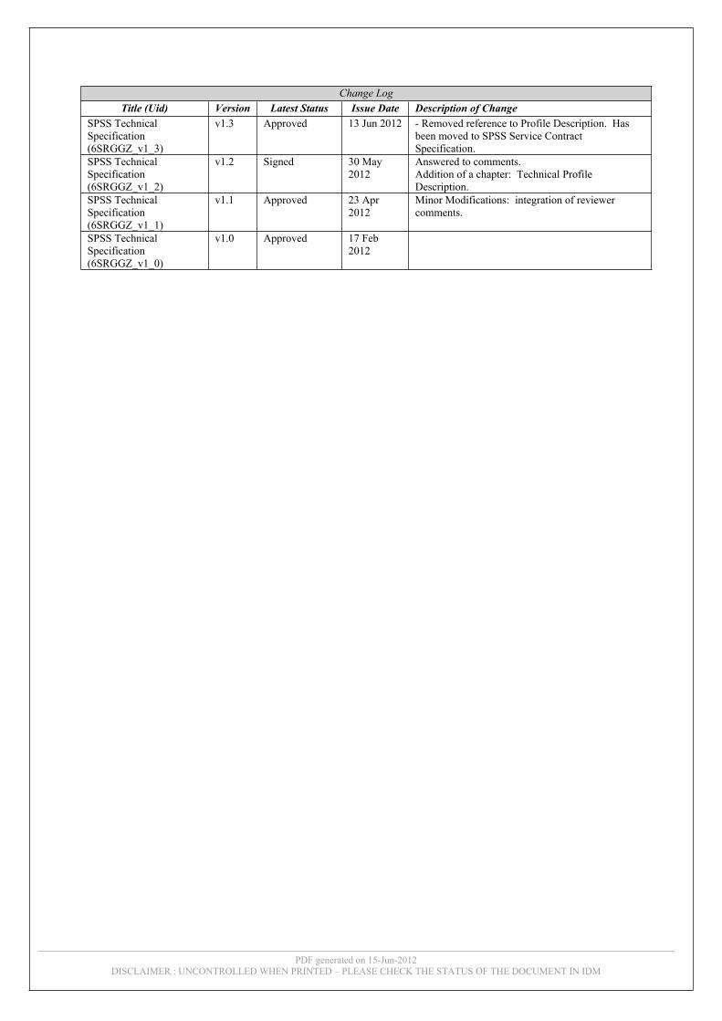
Change LogTitle (Uid) Version Latest Status Issue Date Description of Change
SPSS Technical Specification (6SRGGZ_v1_3)
v1.3 Approved 13 Jun 2012 - Removed reference to Profile Description. Has been moved to SPSS Service Contract Specification.
SPSS Technical Specification (6SRGGZ_v1_2)
v1.2 Signed 30 May 2012
Answered to comments. Addition of a chapter: Technical Profile Description.
SPSS Technical Specification (6SRGGZ_v1_1)
v1.1 Approved 23 Apr 2012
Minor Modifications: integration of reviewer comments.
SPSS Technical Specification (6SRGGZ_v1_0)
v1.0 Approved 17 Feb 2012

SPSS Technical Specification Page 1 of 25
Table of Contents
Table of Contents ........................................................................................................................1Table of Figures...........................................................................................................................21 Introduction.........................................................................................................................3
1.1 Purpose of document ..................................................................................................31.2 Scope.............................................................................................................................31.3 Acronyms.....................................................................................................................31.4 Definitions....................................................................................................................31.5 Reference Documents .................................................................................................4
2 Technical Context ...............................................................................................................53 Generic Requirements of PLC Applications at ITER.....................................................74 Conceptual Architecture of a PLC application................................................................8
4.1 PLC Core Application ................................................................................................94.2 CODAC Interface .....................................................................................................10
4.2.1 Configuration Variables..........................................................................................114.2.2 State Variables ........................................................................................................114.2.3 Simple Commands ..................................................................................................114.2.4 Collaborative Data ..................................................................................................114.2.5 Data Types ..............................................................................................................124.2.6 Redundant Architectures.........................................................................................13
4.3 Hardware Interface ..................................................................................................144.3.1 General Description ................................................................................................144.3.2 Interface Switch ......................................................................................................154.3.3 Filtering...................................................................................................................164.3.4 Engineering Limits..................................................................................................164.3.5 FBS Wrapper ..........................................................................................................164.3.6 Adaptation...............................................................................................................164.3.7 Forcing ....................................................................................................................174.3.8 SIL PLCs.................................................................................................................17
4.4 PLC Interface ............................................................................................................174.5 Fast Controller Interface..........................................................................................184.6 System Monitoring....................................................................................................18
5 Standard PLC Software Structure (SPSS) .....................................................................205.1 Description.................................................................................................................205.2 CODAC Interface in the SPSS.................................................................................21
6 Future Development .........................................................................................................24

SPSS Technical Specification Page 2 of 25
Table of FiguresFigure 1: CODAC Architecture ________________________________________________5Figure 2: PLC Conceptual Architecture__________________________________________8Figure 3: PLC Core Application Environment_____________________________________9Figure 4: Simple Example of CODAC HMI ______________________________________10Figure 5: Collaborative Data _________________________________________________12Figure 6: Hardware Inputs/Outputs Interface Block Diagram _______________________14Figure 7 : Main Cycle Loop Standard Structure __________________________________20Figure 8 : CODAC Interface Standard Structure__________________________________21Figure 9 : Warm Restart Block Standard Structure ________________________________21Figure 10:UDTs and DBs organisation and dependencies for the Control Function
“CWS-DHLT-WFC”. ___________________________________________22Figure 11:UDTs and DBs organisation and dependencies for TCP connexion
parameters. ___________________________________________________23
SPSS Technical Specification Page 3 of 25
1 Introduction
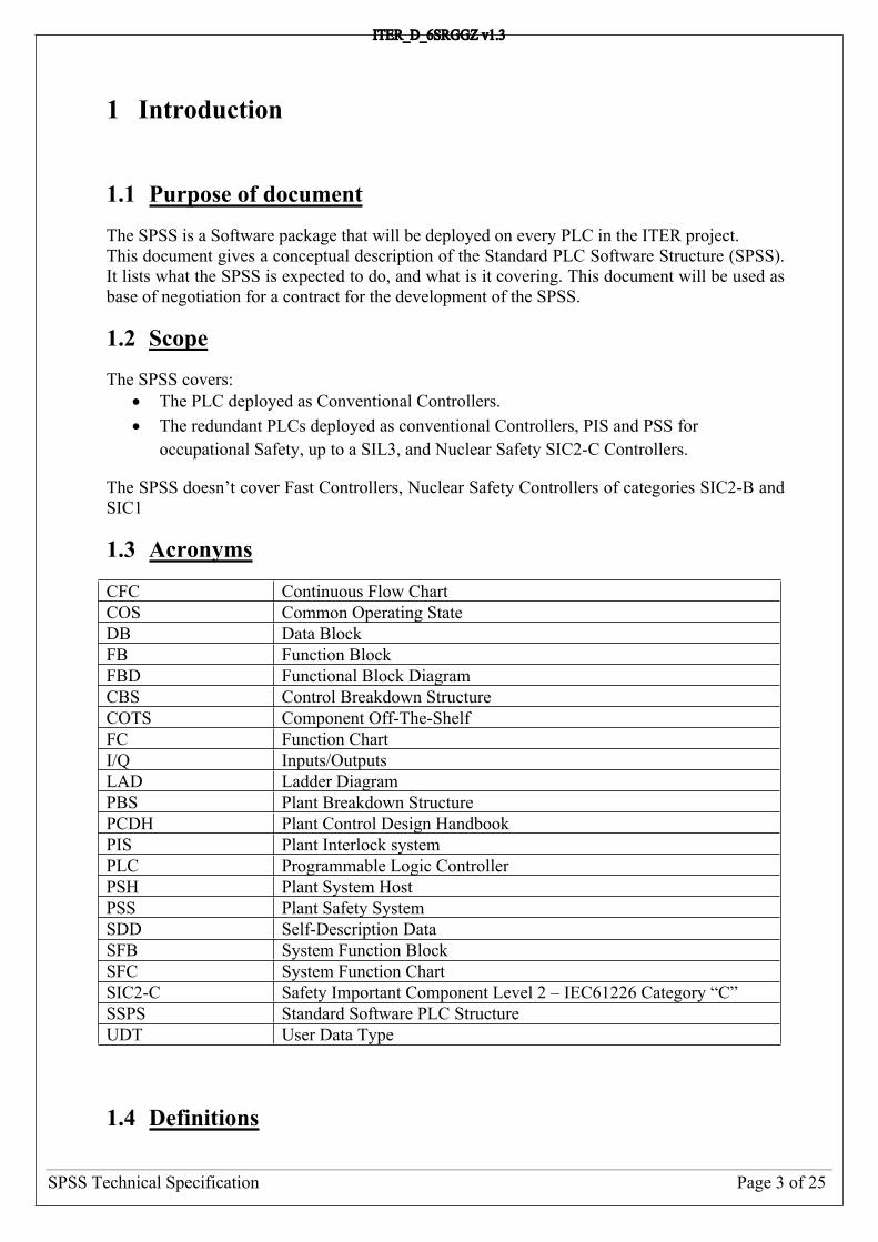
1.1 Purpose of document
The SPSS is a Software package that will be deployed on every PLC in the ITER project. This document gives a conceptual description of the Standard PLC Software Structure (SPSS). It lists what the SPSS is expected to do, and what is it covering. This document will be used as base of negotiation for a contract for the development of the SPSS.
1.2 Scope
The SPSS covers: The PLC deployed as Conventional Controllers. The redundant PLCs deployed as conventional Controllers, PIS and PSS for
occupational Safety, up to a SIL3, and Nuclear Safety SIC2-C Controllers.
The SPSS doesn’t cover Fast Controllers, Nuclear Safety Controllers of categories SIC2-B and SIC1
1.3 Acronyms
CFC Continuous Flow ChartCOS Common Operating StateDB Data BlockFB Function BlockFBD Functional Block DiagramCBS Control Breakdown StructureCOTS Component Off-The-ShelfFC Function ChartI/Q Inputs/OutputsLAD Ladder DiagramPBS Plant Breakdown StructurePCDH Plant Control Design HandbookPIS Plant Interlock systemPLC Programmable Logic ControllerPSH Plant System HostPSS Plant Safety SystemSDD Self-Description DataSFB System Function BlockSFC System Function ChartSIC2-C Safety Important Component Level 2 – IEC61226 Category “C”SSPS Standard Software PLC StructureUDT User Data Type
1.4 Definitions
SPSS Technical Specification Page 4 of 25
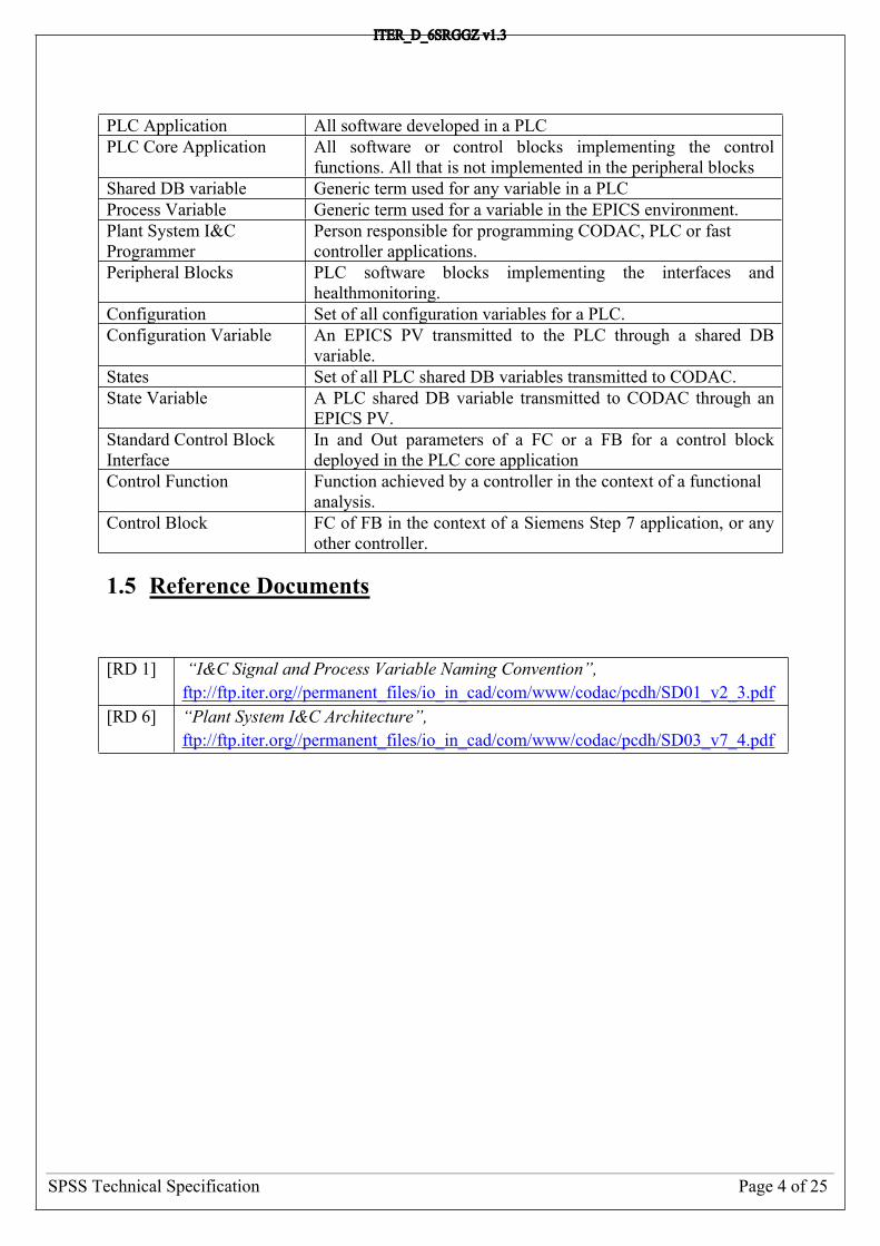
PLC Application All software developed in a PLC PLC Core Application All software or control blocks implementing the control
functions. All that is not implemented in the peripheral blocksShared DB variable Generic term used for any variable in a PLCProcess Variable Generic term used for a variable in the EPICS environment.Plant System I&C Programmer
Person responsible for programming CODAC, PLC or fast controller applications.
Peripheral Blocks PLC software blocks implementing the interfaces and healthmonitoring.
Configuration Set of all configuration variables for a PLC.Configuration Variable An EPICS PV transmitted to the PLC through a shared DB
variable. States Set of all PLC shared DB variables transmitted to CODAC. State Variable A PLC shared DB variable transmitted to CODAC through an
EPICS PV. Standard Control Block Interface
In and Out parameters of a FC or a FB for a control block deployed in the PLC core application
Control Function Function achieved by a controller in the context of a functional analysis.
Control Block FC of FB in the context of a Siemens Step 7 application, or any other controller.
1.5 Reference Documents
[RD 1] “I&C Signal and Process Variable Naming Convention”, ftp://ftp.iter.org//permanent_files/io_in_cad/com/www/codac/pcdh/SD01_v2_3.pdf
[RD 6] “Plant System I&C Architecture”, ftp://ftp.iter.org//permanent_files/io_in_cad/com/www/codac/pcdh/SD03_v7_4.pdf
SPSS Technical Specification Page 5 of 25
2 Technical Context
CODACTerminal
CODAC Server
Channel AccessGateway
PlantSystem
Host
Actuators and Sensors
CODAC Server
CODAC servicesand applications
CODAC Server
CODAC services
CODACTerminalCentral supervision, monitoring and data handling
FastController
CODAC Server
Applications
CODAC Server
Archiving
CentralInterlockSystem
CentralSafety
System
CODAC CISInterface
CODAC CSSInterface
Plant System I&C
ITER Control Group
Safety Controller
SignalInterface
Interlock Controller
SignalInterface
SignalInterface
SignalInterface
SafetyDesk
TCN
CODAC HPCPlasmaControl
TCN
Human Machine Interface
Rest of the worldPON
PON
CIN CSN
FastController
COTSIntelligent
Device
RemoteI/O
RemoteI/O
SlowController
SlowController
TCN
AVN
AVN
DAN
DAN
LegendPON = Plant Operation Network DAN = Data Archive NetworkTCN = Time Communication Network CIN = Central Interlock NetworkSDN = Synchronous Databus Network CSN = Central Safety NetworkAVN = Audio Video Network
CINDAN
SDN
InterlockDesk
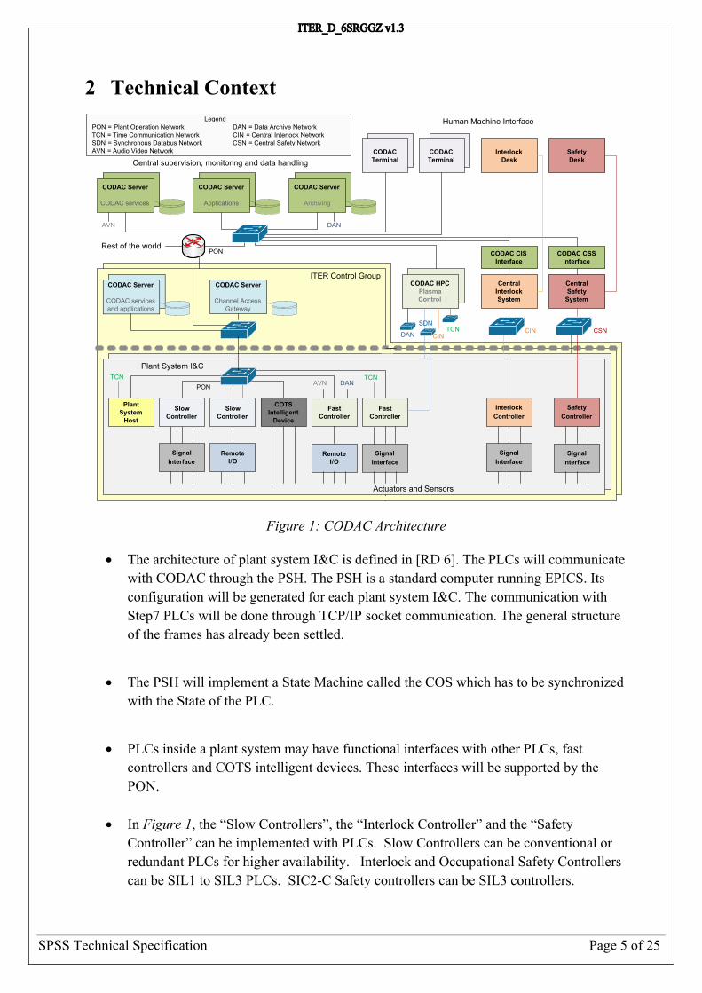
Figure 1: CODAC Architecture
The architecture of plant system I&C is defined in [RD 6]. The PLCs will communicate with CODAC through the PSH. The PSH is a standard computer running EPICS. Its configuration will be generated for each plant system I&C. The communication with Step7 PLCs will be done through TCP/IP socket communication. The general structure of the frames has already been settled.
The PSH will implement a State Machine called the COS which has to be synchronized with the State of the PLC.
PLCs inside a plant system may have functional interfaces with other PLCs, fast controllers and COTS intelligent devices. These interfaces will be supported by the PON.
In Figure 1, the “Slow Controllers”, the “Interlock Controller” and the “Safety Controller” can be implemented with PLCs. Slow Controllers can be conventional or redundant PLCs for higher availability. Interlock and Occupational Safety Controllers can be SIL1 to SIL3 PLCs. SIC2-C Safety controllers can be SIL3 controllers.
SPSS Technical Specification Page 6 of 25
The Interlocks and Safety Controllers are separated from the conventional control, in strict compliance with IEC61508. Meanwhile, they could be connected to the CODAC, for monitoring purposes.
SPSS Technical Specification Page 7 of 25
3 Generic Requirements of PLC Applications at ITER
- Flexibility.
o During integration and commissioning, all interfaces may be not available. The application should allow some signals to be forced, or the partial simulation of the missing interface.
- Maintainability
o Sufficient system information should be provided.
o The PLC application should be modular so that modifications have only local impact.
o The design of the application should take into account at least one major Hardware Upgrade. The underlying requirement is code portability.
- Ability to be tested.
o Unit testing of PLC Control Blocks should be easy.
o Control systems software should be tested independently from the system. The idea is to test the control system when it is connected to a simulator rather than the system. The plant system designer has to define beforehand which controllers have to be tested together.
- Readability
o Every information transformation in the data flow should be easy to track.
SPSS Technical Specification Page 8 of 25
4 Conceptual Architecture of a PLC application.
7
3
PLC
CODAC interface
Hardware Outputs/Inputs Interface
4
PLC Interface
Plant Systems Equipment
Simulator
CODAC Core System
11
13 Fast Controller
Interface(s)6 Fast
Controller(s)
PLC(s)
2
1
7
System Monitoring
8
10
9 12
PLC Core Application
5
1
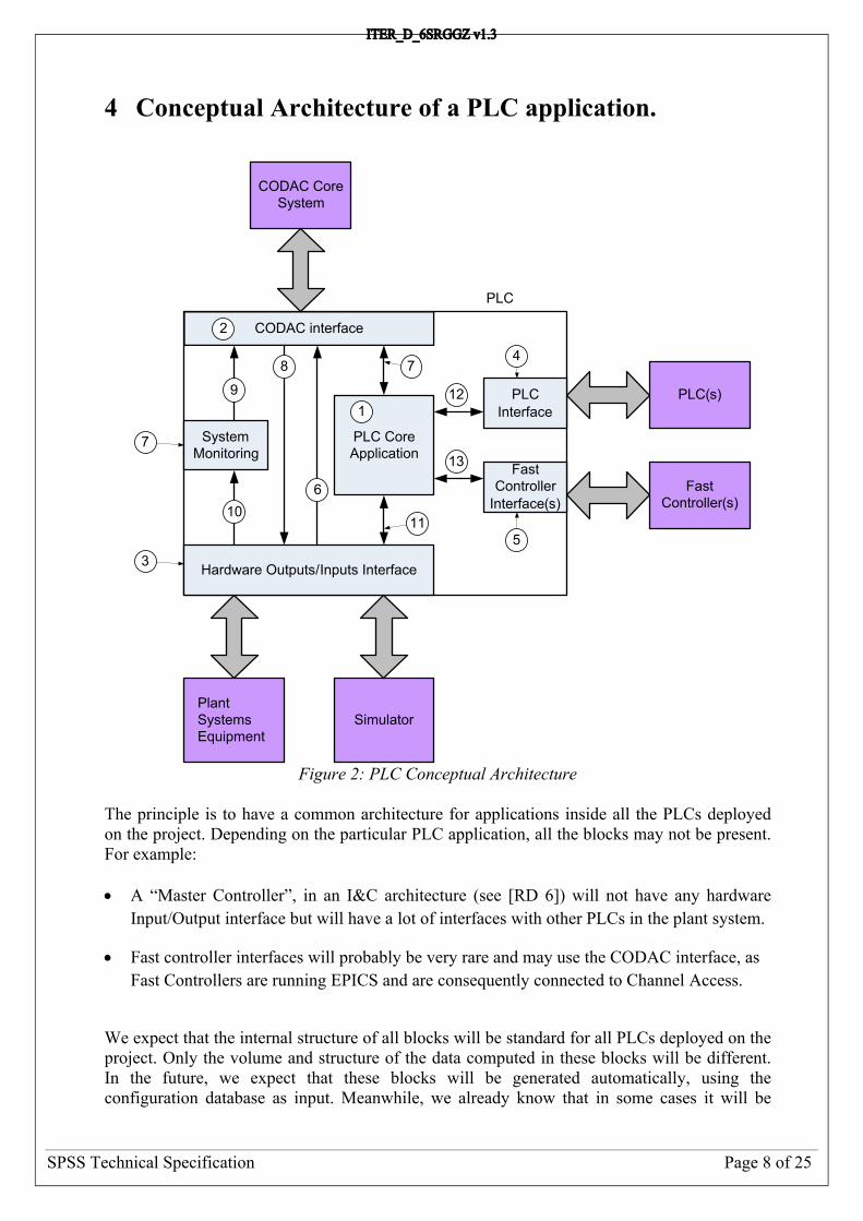
Figure 2: PLC Conceptual Architecture
The principle is to have a common architecture for applications inside all the PLCs deployed on the project. Depending on the particular PLC application, all the blocks may not be present. For example:
A “Master Controller”, in an I&C architecture (see [RD 6]) will not have any hardware Input/Output interface but will have a lot of interfaces with other PLCs in the plant system.
Fast controller interfaces will probably be very rare and may use the CODAC interface, as Fast Controllers are running EPICS and are consequently connected to Channel Access.
We expect that the internal structure of all blocks will be standard for all PLCs deployed on the project. Only the volume and structure of the data computed in these blocks will be different. In the future, we expect that these blocks will be generated automatically, using the configuration database as input. Meanwhile, we already know that in some cases it will be

SPSS Technical Specification Page 9 of 25
difficult to have exactly the same structure. It will be developed in the following chapters. For conventional Controllers, The CODAC interface (“2”on Figure 2) will be fully generated by the SDD package.
In the document, Blocks 2, 3, 4, 5, 7 of Figure 2 are called the “Peripheral Blocks”, in the sense that these blocks embeds “peripheral” features. In opposition to the “PLC Core Application”, embedding the Central Logic.
4.1 PLC Core Application
The PLC core application (“1”on Figure 2) is the place where the control logic, GRAFCETS, state charts and regulation loops of the process will be implemented. Only process programming should be found here. The PLC core application will implement the control functions. Its functionality will be affected by all the interfaces on Figure 2. All programming or treatment not directly involving the process is performed in the peripheral blocks (interfaces, system monitoring).
CODAC Interface
PLC Core Application
Configuration Variables
Simple Commands
Collaborative Datas
State Variables
Hardware Outputs/Inputs interface
Outputs Inputs
ControllerInterface(s)
PLC
Figure 3: PLC Core Application Environment
The PLC core application will use the configuration variables (see Figure 3) transmitted by the CODAC interface as the main inputs from operation. Some configuration variable examples:
- ON/OFF state requests- OPEN/CLOSE state requests,- HIGH VACUUM/ROUGHING/VENTING request, - Current setpoint, - Temperature setpoint- …

SPSS Technical Specification Page 10 of 25
Hardware inputs and outputs (See Figure 3) are in engineering format. The PLC core application is insensitive to the fact that these values may be coming from real equipment or are simulated or forced. The PLC core application will compute the CODAC configuration variables and the hardware inputs and generate the outputs in order to reach the configuration requested. The state variables report the effective state of the process. The main principle is that it is always possible to have an easy comparison in CODAC between the state (configuration) of the process that was requested and the actual state. A simple example of what a CODAC HMI for a simple device is given in Figure 4.
Power SupplyPower Supply
ON
0.0095.00Amps
Fuse OK
Water Cooling NOK
Temperature OK
Interlocks
24 VDC OK
Power OK
Configuration State
Amps
OFF
Power SupplyPower Supply
ON
95.0095.00Amps
Fuse OK
Water Cooling NOK
Temperature OK
Interlocks
24 VDC OK
Power OK
Configuration State
Amps
ON
Easy Comparaison of Configuration and State
Easy Comparaison of Configuration and State
Normal Operation Off - Normal Operation
Figure 4: Simple Example of CODAC HMI
Collaborative data (See Figure 3) are state variables produced by other plant systems and transmitted by CODAC core system. Transverse wired links between plant systems are strictly forbidden. Transmission of information between plant systems will use the collaborative data link. The interfaces with other controllers in same plant system I&C also have an impact on the processing and this aspect will be developed in § 4.4 and § 4.5.
4.2 CODAC Interface
The main function of the CODAC interface (“2”in Figure 2 ) is to manage the PLC side of the communication with CODAC, which is developed in an EPICS environment. The CODAC side of the communication is managed by a specific driver in the PSH .This communication decomposes in 4 categories, as represented in Figure 3:
- Configuration variables- State variables- Simple commands
SPSS Technical Specification Page 11 of 25
- Collaborative data
4.2.1 Configuration Variables
The main use of configuration variables is described in § 4.1. In Figure 2 the link “8” shows another use of these variables: giving configuration to the hardware I/O interface. Mainly, it will provide conversion of parameters from physical to engineering units, forcing values and inhibits, it will also affect the simulation mode. It is described in § 4.3
4.2.2 State Variables
The state variables are used to transmit the state of the process:- Directly from the hardware I/O interface (“6”in Figure 2 ). This direct link is necessary
as the CODAC core applications use these variables without requiring computing in the PLC core application. It is important to note here that these variables are in engineering units, and they can also be forced or simulated.
- From the computed variables issued by the PLC core application (“7”in Figure 2 ). - From the system monitoring (“9”in Figure 2 ).
4.2.3 Simple Commands
Simple commands are variables set to “TRUE” during one cycle in the PLC. These simple commands are used in the cases where it is not necessary to memorize the action related to this command, as is the case for configuration variables. Typical examples are “Reset” of some devices. Reset is not a stable configuration, it is a transient command.
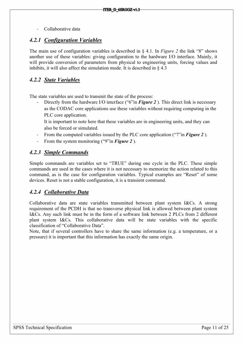
4.2.4 Collaborative Data
Collaborative data are state variables transmitted between plant system I&Cs. A strong requirement of the PCDH is that no transverse physical link is allowed between plant system I&Cs. Any such link must be in the form of a software link between 2 PLCs from 2 different plant system I&Cs. This collaborative data will be state variables with the specific classification of “Collaborative Data”. Note, that if several controllers have to share the same information (e.g. a temperature, or a pressure) it is important that this information has exactly the same origin.
SPSS Technical Specification Page 12 of 25
Figure 5: Collaborative DataInterlock and Safety Controllers will not use this channel to communicate between them. They will always transmit their information through a Central Controller (CSS, CIS). It is strictly not recommended to use this channel to influence the behaviour of Safety and Interlock Controllers.
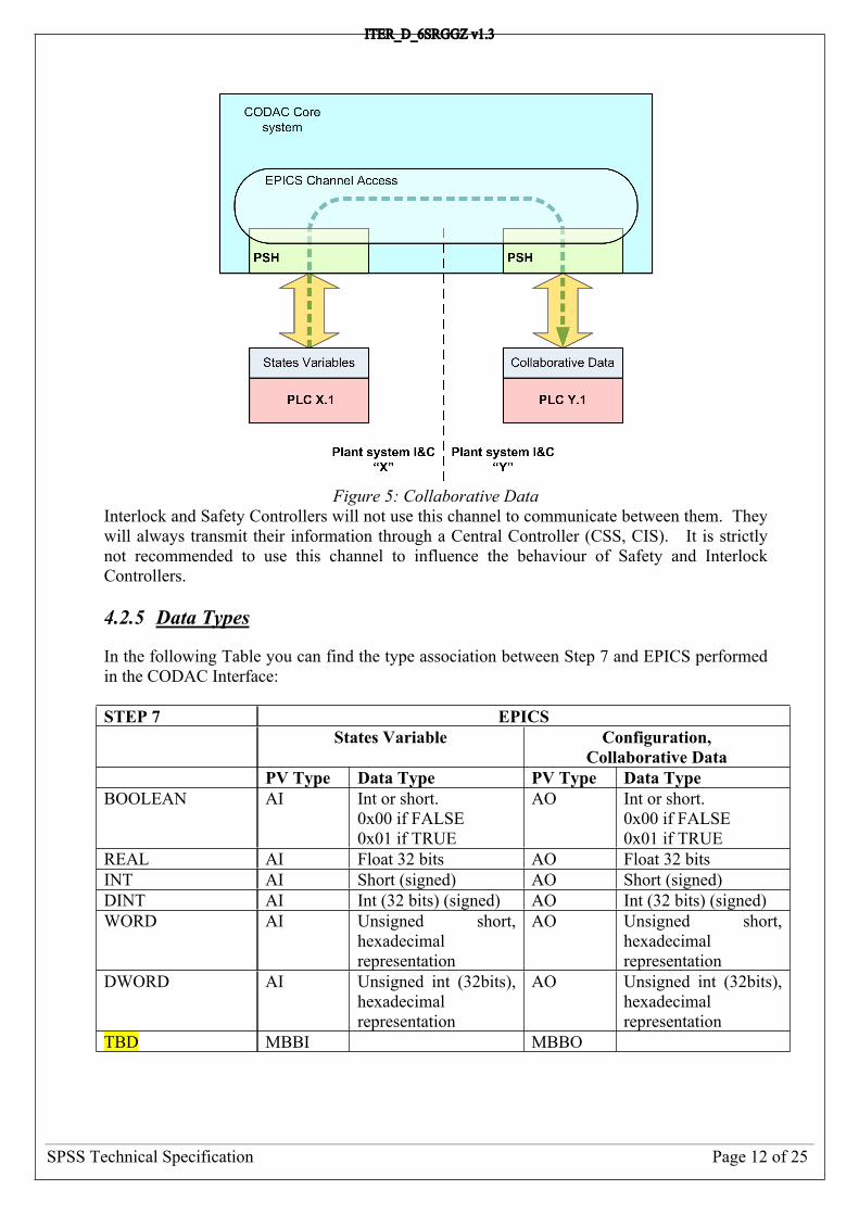
4.2.5 Data Types
In the following Table you can find the type association between Step 7 and EPICS performed in the CODAC Interface:
STEP 7 EPICSStates Variable Configuration,
Collaborative DataPV Type Data Type PV Type Data Type
BOOLEAN AI Int or short. 0x00 if FALSE0x01 if TRUE
AO Int or short. 0x00 if FALSE0x01 if TRUE
REAL AI Float 32 bits AO Float 32 bitsINT AI Short (signed) AO Short (signed)DINT AI Int (32 bits) (signed) AO Int (32 bits) (signed)WORD AI Unsigned short,
hexadecimal representation
AO Unsigned short, hexadecimal representation
DWORD AI Unsigned int (32bits), hexadecimal representation
AO Unsigned int (32bits), hexadecimal representation
TBD MBBI MBBO

SPSS Technical Specification Page 13 of 25
For Simple Commands, it is a BOOLEAN variable on Step 7 Side. On EPICS Side, it is a bit that is set to “0x1” during 300msec. During these 300msecs, it is transmitted to the PLC. In the PLC, this bit has to be set to “TRUE” during one cycle of the PLC program.
4.2.6 Redundant Architectures
For High Availability, Interlock and Safety Controllers, redundant Architectures will be deployed. The CODAC Interface will take this feature into account.

SPSS Technical Specification Page 14 of 25
4.3 Hardware Interface
4.3.1 General Description
FilteringLow-pass Anti-Rebounce
Codac Interface
Plant System Plant System Simulator
“Forcing” “Forcing”
Configuration
Digital
States
PLC Core Application
CBS Wrapper CBS Wrapper
Hardware Outputs interface
Analog
Engineering Limits
Analog Digital
AdaptationScaling Standardiza-tion AdaptationScaling Standardiza-
tion
Interface SwitchTCP/IPET200M
Interface SwitchTCP/IPET200M
Wiring TCP Socket
PLC
CODAC
Har
dwar
e In
puts
inte
rf ac e
Har
dwar
e O
u tpu
ts In
ter fa
ce
Figure 6: Hardware Inputs/Outputs Interface Block Diagram
The hardware interface is divided in two parts: the input interface and the output interface. Almost the same functions are present in both parts but they are processed in the opposite
SPSS Technical Specification Page 15 of 25
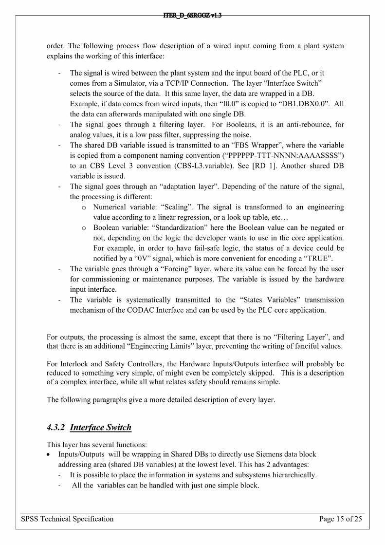
order. The following process flow description of a wired input coming from a plant system explains the working of this interface:
- The signal is wired between the plant system and the input board of the PLC, or it comes from a Simulator, via a TCP/IP Connection. The layer “Interface Switch” selects the source of the data. It this same layer, the data are wrapped in a DB. Example, if data comes from wired inputs, then “I0.0” is copied to “DB1.DBX0.0”. All the data can afterwards manipulated with one single DB.
- The signal goes through a filtering layer. For Booleans, it is an anti-rebounce, for analog values, it is a low pass filter, suppressing the noise.
- The shared DB variable issued is transmitted to an “FBS Wrapper”, where the variable is copied from a component naming convention (“PPPPPP-TTT-NNNN:AAAASSSS”) to an CBS Level 3 convention (CBS-L3.variable). See [RD 1]. Another shared DB variable is issued.
- The signal goes through an “adaptation layer”. Depending of the nature of the signal, the processing is different:
o Numerical variable: “Scaling”. The signal is transformed to an engineering value according to a linear regression, or a look up table, etc…
o Boolean variable: “Standardization” here the Boolean value can be negated or not, depending on the logic the developer wants to use in the core application. For example, in order to have fail-safe logic, the status of a device could be notified by a “0V” signal, which is more convenient for encoding a “TRUE”.
- The variable goes through a “Forcing” layer, where its value can be forced by the user for commissioning or maintenance purposes. The variable is issued by the hardware input interface.
- The variable is systematically transmitted to the “States Variables” transmission mechanism of the CODAC Interface and can be used by the PLC core application.
For outputs, the processing is almost the same, except that there is no “Filtering Layer”, and that there is an additional “Engineering Limits” layer, preventing the writing of fanciful values.
For Interlock and Safety Controllers, the Hardware Inputs/Outputs interface will probably be reduced to something very simple, of might even be completely skipped. This is a description of a complex interface, while all what relates safety should remains simple.
The following paragraphs give a more detailed description of every layer.
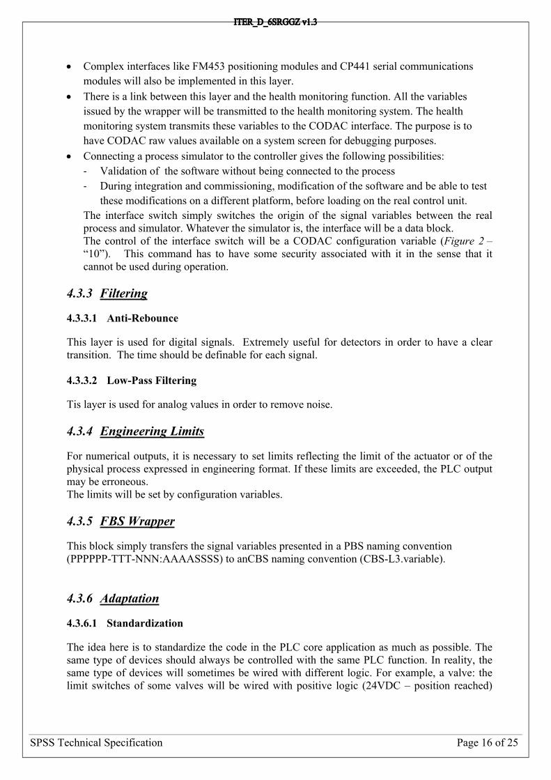
4.3.2 Interface Switch
This layer has several functions: Inputs/Outputs will be wrapping in Shared DBs to directly use Siemens data block
addressing area (shared DB variables) at the lowest level. This has 2 advantages: - It is possible to place the information in systems and subsystems hierarchically.- All the variables can be handled with just one simple block.
SPSS Technical Specification Page 16 of 25
Complex interfaces like FM453 positioning modules and CP441 serial communications modules will also be implemented in this layer.
There is a link between this layer and the health monitoring function. All the variables issued by the wrapper will be transmitted to the health monitoring system. The health monitoring system transmits these variables to the CODAC interface. The purpose is to have CODAC raw values available on a system screen for debugging purposes.
Connecting a process simulator to the controller gives the following possibilities:- Validation of the software without being connected to the process- During integration and commissioning, modification of the software and be able to test
these modifications on a different platform, before loading on the real control unit.The interface switch simply switches the origin of the signal variables between the real process and simulator. Whatever the simulator is, the interface will be a data block.The control of the interface switch will be a CODAC configuration variable (Figure 2 – “10”). This command has to have some security associated with it in the sense that it cannot be used during operation.
4.3.3 Filtering
4.3.3.1 Anti-Rebounce
This layer is used for digital signals. Extremely useful for detectors in order to have a clear transition. The time should be definable for each signal.
4.3.3.2 Low-Pass Filtering
Tis layer is used for analog values in order to remove noise.
4.3.4 Engineering Limits
For numerical outputs, it is necessary to set limits reflecting the limit of the actuator or of the physical process expressed in engineering format. If these limits are exceeded, the PLC output may be erroneous.The limits will be set by configuration variables.
4.3.5 FBS Wrapper
This block simply transfers the signal variables presented in a PBS naming convention (PPPPPP-TTT-NNN:AAAASSSS) to anCBS naming convention (CBS-L3.variable).
4.3.6 Adaptation
4.3.6.1 Standardization
The idea here is to standardize the code in the PLC core application as much as possible. The same type of devices should always be controlled with the same PLC function. In reality, the same type of devices will sometimes be wired with different logic. For example, a valve: the limit switches of some valves will be wired with positive logic (24VDC – position reached)

SPSS Technical Specification Page 17 of 25
and some with negative logic (0VDC – position reached) whilst control of the valve is identical. The function of this standardization block would be to process the negation required for all discrete signals, in order to present a standard signal interface for the different types of devices to the PLC core application.All the negation parameters will be provided by CODAC configuration variables.
4.3.6.2 Scaling
Conversion from 16 bits integer to physical unit will be required for most of the numerical signal variables. This conversion can be linear, quadratic or of superior orders. It can also be a look-up table. All the conversion parameters will be provided by CODAC configuration variables.
4.3.7 Forcing
During integration, commissioning and sometimes during maintenance, it is normal that engineers will want to force some signal variables to a specific value, because the related signal is not connected, missing, is not operational or has failed. It is better to take this fact into account in the software design, so that this “irregular” (and possibly dangerous) behaviour will be controlled. The aim is to avoid dangerous “temporary-permanent” practices like forcing a signal with PLC hardcoded modifications, hardwired modifications, strapping of relays etc. This forcing layer has to be developed and in particular:
- some signals cannot be forced at any time because this could be destructive.- The control unit (or the all I&C) may not be able to reach an operational state as long as
signal variables are forced.- Inhibiting this forcing feature.
All permanent and runtime parameters will be provided by CODAC configuration variables.
4.3.8 SIL PLCs
With SIL PLCs, the organization of Inputs and outputs can become quite complex. You can have redundancies of signals, of acquisition chains, Votes 1oo2, 2oo3, etc…. Making the Hardware Interface much more complex if you want to reach the abstraction level described in this chapter.
4.4 PLC Interface
This interface addresses communications between: PLCs of a same plant system I&C, A Plant Safety or an Interlock Controller and its Central Controller,
for the case where a functional interface is required. The Siemens protocol to be used has to be defined. From a conceptual point of view, one can consider 3 different cases:
- A master/slave link where the master PLC is sending commands (Boolean or numerical) to a slave PLC
SPSS Technical Specification Page 18 of 25
- A point-to-point link where 2 PLCs are exchanging states. This state transmission can be I/O of another PLC.
- A multipoint communication where a PLC is publishing states to a group of PLCs.
In a master/slave architecture, the master coordinator sends orders to the slaves. A communication paradigm has to be defined for these orders.
Each case will be implemented with the most appropriate Siemens technology.
4.5 Fast Controller Interface
This interface addresses communications between a PLC and a fast controller. 3 cases are considered:
- A master/slave link where the PLC is sending orders (Boolean or numerical) to a fast controller.
- A master/slave link where the fast controller is sending orders (Boolean or numerical) to a PLC.
- A point-to-point link where a Fast controller and a PLC are exchanging states.
In a master/slave architecture, the master will send orders to the slaves. A communication paradigm has to be defined for these orders.
4.6 System Monitoring
A task will be dedicated to PLC system monitoring: the following parameters will be monitored:
Operating Mode: RUN/STOP Memory:
o Load memory assigned: 0..100%o Work memory assigned: 0..100%o Retentive: 0..100%
Scan cycles:o Shortesto Longesto Averageo Standard deviation
CPU Time: Date and hour Communication
o Configuredo Max numbers of connections availableo Number of connections used
I/Os:o 24VDC Statuseso Board statuseso Raw value of each signal

SPSS Technical Specification Page 19 of 25
Alive counter. Total Time Counter.
For redundant Architectures, monitored information will be specific and the volume to will be much bigger
SPSS Technical Specification Page 20 of 25
SPSS Technical Specification Page 21 of 25
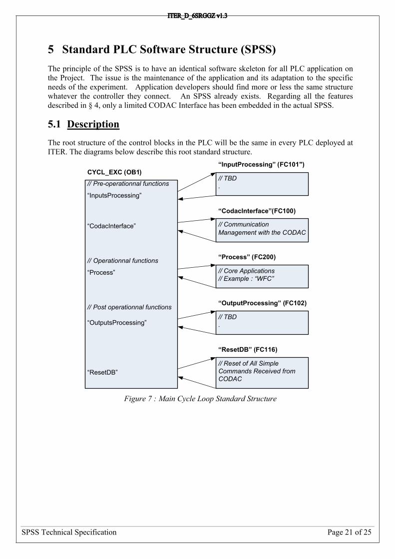
5 Standard PLC Software Structure (SPSS)The principle of the SPSS is to have an identical software skeleton for all PLC application on the Project. The issue is the maintenance of the application and its adaptation to the specific needs of the experiment. Application developers should find more or less the same structure whatever the controller they connect. An SPSS already exists. Regarding all the features described in § 4, only a limited CODAC Interface has been embedded in the actual SPSS.
5.1 Description
The root structure of the control blocks in the PLC will be the same in every PLC deployed at ITER. The diagrams below describe this root standard structure.
CYCL_EXC (OB1)
// Core Applications// Example : “WFC”
“Process” (FC200)
// TBD.
“InputProcessing” (FC101")
// TBD.
“OutputProcessing” (FC102)
// Reset of All Simple Commands Received from CODAC
“ResetDB” (FC116)
// Pre-operationnal functions
“InputsProcessing”
“CodacInterface”
“Process”
// Operationnal functions
“OutputsProcessing”
“ResetDB”
// Post operationnal functions
// Communication Management with the CODAC
“CodacInterface”(FC100)
Figure 7 : Main Cycle Loop Standard Structure

SPSS Technical Specification Page 22 of 25
“CodacChannel”,”iCondacchannel1"
// States and Configuration Variables
“CodacChannel”,”iCondacchannel2"
// Simple Commands
“CodacInterface”(FC100)
“CodacChannel”(FB110)
"CodacSetTcpEndPointx"
“T_CONN”
“T_SEND”
“T_RECV”
// TCP Connection Control
“PulseGenerator”,”iCodacPace"
“CodacTimeStamp”,”iCodacTimeStamp"
// Read the System Time“READ_CLCK”
// Generation of a pulse every 50msecs
“PulseGenerator”(FB100)
Figure 8 : CODAC Interface Standard Structure
WARM_START (OB100)
“CodacConnectionInit”// Initialization of TCP Communication port at Startup
“CodacConnectionInit”(FC115)
Figure 9 : Warm Restart Block Standard Structure
This standard structure is actually developed and maintained by ITER. It has to be imported in any application before developing or setting up the peripheral blocks and the core application.
5.2 CODAC Interface in the SPSS
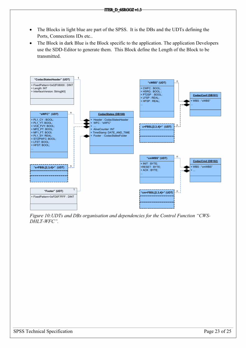
In the actual SPSS, the CODAC Interface is supported. In Figure 8, the fixed application part of the CODAC interface is described. Globally it is managing the Legacy Communication Blocks of Siemens: “T_CON”, T_SEND”,” T_RECV”. The only missing part is the data to be transmitted, their location, the length, etc…In Figure 10 the Blocks represent the Shared DBs to be transmitted to the CODAC: The Blocks in light blue are part of the SPSS. It is the fixed part of the DBs: the UDT
defining the Headers/Footers. The Blocks in dark Blue are the Blocks specific to the application. The application
Developers use a tool called the SDD-Editor to generate them. In the example of the figures, it is a Water Cooling Function.
In Figure 11, the Blocks represent the Shared DBs, with the TCP parameters of the communication.
SPSS Technical Specification Page 23 of 25
The Blocks in light blue are part of the SPSS. It is the DBs and the UDTs defining the Ports, Connections IDs etc..
The Block in dark Blue is the Block specific to the application. The application Developers use the SDD-Editor to generate them. This Block define the Length of the Block to be transmitted.
“cWBS” (UDT)
+ CWFC : BOOL;+ HSRQ : BOOL ;+ PT2SP : BOOL;+ LFSP : REAL;+ HFSP : REAL;...
“sWFC” (UDT)
+ PL1_CY : BOOL;+ PL1_YT: BOOL;+ VC8_FVY: BOOL;+ MP2_PT: BOOL;+ MF1_FT: BOOl;+ PL1_SY: REAL;+ STOPWFC: BOOL;+ LFST: BOOL;+ HFST: BOOL;...
CodacConf (DB101)
+ WBS : “cWBS”...
CodacStates (DB100)
+ Header : CodacStatesHeader+ WFC : “sWFC”+ …+ AliveCounter: INT+ TimeStamp: DATE_AND_TIME + Footer : CodacStatesFooter
“CodacStatesHeader” (UDT)
+ FixedPattern=0x02F08000 : DINT + Length: INT+ InterfaceVersion: String[40]
“Footer” (UDT)
+ FixedPattern=0xFD0F7FFF : DINT
“cmWBS” (UDT)
+ INIT : BYTE;+RESET : BYTE;+ ACK : BYTE;...
CodacCmd (DB102)
+ WBS : “cmWBS”+ ...
“s<FBSL[2,3,4]>” (UDT)
“cm<FBSL[2,3,4]>” (UDT)
c<FBSL[2,3,4]>” (UDT)
1
n
1
n
n
n
n
n
Figure 10:UDTs and DBs organisation and dependencies for the Control Function “CWS-DHLT-WFC”.

SPSS Technical Specification Page 24 of 25
CodacConnections (DB103)
+ Channel1 : “_CodacConnection”;+ Channel2 : “_CodacConnection”;
“_CodacConnection” (UDT)
+ CONN_ID : INT;+ DEV_ID : BYTE;+ PORT : INT;+ INIT_COM : BOOL;+ SEND_DB : BYTE;+ RECV_DB : BYTE;
2
CodacChannels (DB104)
+ Channel1 : “_CodacChannel”;+ Channel2 : “_CodacChannel”;
“_CodacChannel” (UDT)
+ SEND_LEN : INT;+ RECV_LEN : INT;
n
Figure 11:UDTs and DBs organisation and dependencies for TCP connexion parameters.

SPSS Technical Specification Page 25 of 25
6 Future DevelopmentThe ultimate target is to have the SPSS supporting all features of the Peripheral Blocks described in the Conceptual Architecture:
Codac Interfaceo It should support redundant architectureso It should be customizable for the Interface to be choosen: CP or CPU.
System Monitoring, System Monitoring for Redundant Architectures PLC interface. All cases should be considered: Conventional to Conventional,
Conventional to Redundant. Redundant to Redundant. Fast Controller Interface, with Conventional and Redundant. Hardware interface:
o For Conventional Controllers: For “Functional Boards”: Positioning, Counting, Fast I/Os For Specific Communication Boards: RS232, RS485, Modbus, Modbus
TCP.o For Redundant Architectures
In a high Availability Context In a Safety or Interlock Context (IEC61508)
The actual SPSS is developed with conventional languages. It should be possible to start from a CFC application.