SPS Small Fragment Set - Cambridge Orthopaedics · Axial compression can therefore be ... Closed...
20
SPS Small Fragment Set • Features and Benefits • Indications • Operative Technique • Ordering Information
Transcript of SPS Small Fragment Set - Cambridge Orthopaedics · Axial compression can therefore be ... Closed...

SPSSmall Fragment Set
• Features and Benefits• Indications• Operative Technique• Ordering Information
2
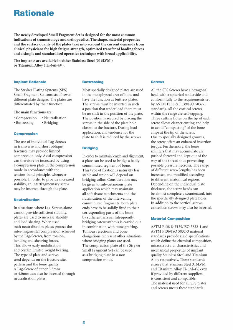
Rationale
Implant Rationale
The Stryker Plating Systems (SPS)Small Fragment Set consists of sevendifferent plate designs. The plates aredifferentiated by their function.
The main functions are:
• Compression • Neutralisation • Buttressing • Bridging
Compression
The use of individual Lag-Screws in transverse and short obliquefractures may provide limitedcompression only. Axial compressioncan therefore be increased by using a compression plate in the compressionmode in accordance with the tension-band principle, wheneverpossible. In order to provide increasedstability, an interfragmentary screwmay be inserted through the plate.
Neutralisation
In situations where Lag-Screws alonecannot provide sufficient stability,plates are used to increase stability and load sharing. When used,such neutralisation plates protect the inter-fragmental compression achieved by the Lag-Screws, from torsion,bending and shearing forces.This allows early mobilisation and certain limited weight bearing.The type of plate and screws used depends on the fracture site,pattern and the bone quality.A Lag-Screw of either 3.5mm or 4.0mm can also be inserted throughneutralisation plates.
Buttressing
Most specially designed plates are usedin the metaphyseal area of bone andhave the function as buttress plates.The screws must be inserted in such a position that under load there mustbe no shift in the position of the plate.The position is secured by placing thescrews in the side of the plate holeclosest to the fracture. During loadapplication, any tendency for the plate to shift is reduced by the screws.
Bridging
In order to maintain length and alignment,a plate can be used to bridge a badlycomminuted segment of bone.This type of fixation is naturally lessstable and union will depend onbridging callus. Consideration may be given to sub-cutaneous plateapplication which may maintain all soft tissue attachments and thenutrification of the interveningcomminuted fragments. Both plateends have to be solidly fixed to theircorresponding parts of the bone by sufficient screws. Infrequently,bridging osteosynthesis is carried outin combination with bone grafting.Tumour resections and boneelongations represent other situationswhere bridging plates are used.The compression plate of the StrykerSmall Fragment Set can be used as a bridging plate in a noncompression mode.
Screws
All the SPS Screws have a hexagonalhead with a spherical underside andconform fully to the requirements setby ASTM F138 & F139/ISO 5832-1standards. All the cortical screwswithin the range are self-tapping.Three cutting flutes on the tip of eachscrew allows cleaner cutting and helpto avoid “compacting” of the bonechips at the tip of the screw.Due to specially designed grooves,the screw offers an enhanced insertiontorque. Furthermore, the bonesplinters that may accumulate arepushed forward and kept out of theway of the thread thus preventingpossible pressure necrosis. The rangeof different screw lengths has beenincreased and modified according to different anatomical regions.Depending on the individual platethickness, the screw heads can be almost completely countersunk intothe specifically designed plate holes.In addition to the cortical screws,cancellous screws may also be inserted.
Material Composition
ASTM F138 & F139/ISO 5832-1 andASTM F136/ISO 5832-3 materialstandards provide rigid specificationswhich define the chemical composition,microstructural characteristics andmechanical properties of implantquality Stainless Steel and TitaniumAlloy respectively. These standardsensure that Stainless Steel 316LVM and Titanium Alloy Ti-6Al-4V, even if provided by different suppliers,is consistent and compatible.The material used for all SPS platesand screws meets these standards.
The newly developed Small Fragment Set is designed for the most commonindications of traumatology and orthopaedics. The shape, material propertiesand the surface quality of the plates take into account the current demands fromclinical physicians for high fatigue strength, optimised transfer of loading forcesand a simple and standardised operative technique with broad applicability.
The implants are available in either Stainless Steel (316LVM ) or Titanium Alloy ( Ti-6Al-4V).

3
Clinical Design Team
Prof. Thierry BéguéHôpital Avicenne, Paris, France
Prof. Dr. med. Volker BührenBG Unfallklinik, Murnau, Germany
Gary S. Gruen M.D.University of Pittsburgh Medical Center, Pittsburgh, USA
Prof. Dr. med. Hans-UlrichLangendorffUnfallklinik, Klinikum Dortmund,Germany
Michael Prayson M.D.University of Pittsburgh Medical Center, Pittsburgh, USA
Robert Probe M.D.Scott and White Memorial Hospital,Texas, USA
Melvin Rosenwasser M.D.Columbia Presbyterian MedicalCenter, New York, USA
We would also like to thank various Operating Room Nurses and Sterilisation Staff for their help during the pre-market evaluation period.
The System is designed with the kind collaboration of the following Surgeons:
Introduction

4
Introduction
Cases and TraysThe Small Fragment Set consists of a single outer base available in plastic or metal containing fourremovable inserts. The two plate racks,screw rack and tray insert offeroptimum modularity for storage andsterilisation. The vertical “pop-up”rack allows for easy access to all theinstruments which are arranged in a logical order, whilst minimising“overhang” on the instrument table.
ScrewsIn addition to the standard 3.5mm and 4.0mm screw range,the Small Fragment Set also has theoption to include a select range of2.7mm self-tapping cortical screws.These can offer the option to performindependent interfragmentary Lag-Screws compression without theneed for an additional implant set.
Drills and TapsContained within the set are all therelevant drill bits and taps correspondingto each screw diameter. Titaniumoxide coating on the 3.5mm drill bitand tap enhances not only the cuttingefficiency but the longevity andimproved visual identity of eachinstrument. Whilst all of the corticalscrews in the set are self-tapping,the inclusion of the tap offersclinicians the option of pre-tapping in dense cortical bone.

5
Features and Benefits
The system design is based on input from key clinicians, theatre andsterilisation staff, data from literature and both practical and biomechanicaltesting results of the system.
Features Benefits
Stainless Steel • Patient compatibility or Titanium implant range and surgeon preference
Multiple plate options • Increased indication coverage all in one set
Rounded and tapered plate ends • Reduced potential for soft-tissue irritation Easier placement of plate during sub-cutaneous insertion
3.5/4.0mm screw hole options • Flexibility of cortical or cancellous screws
K-wire and reduction holes • Enhanced primary/temporary plate and fracture fixation
Equal hole spacing on straight plates • Greater operative flexibility for screw and plate placement
Low screw head profile in plate hole • Reduced potential for soft-tissue irritation
Annealed Reconstruction plate • Optimal three dimensional bending
Uniform bending stiffness • Equal bending force distributionin Waisted Compression plate for increased fatigue strength
and contourability
Speciality Reconstruction • Extended indications and Calcaneal plates in set
Bi-directional holes • Allows compression and/or distraction
Self-tapping screws • Quick, simple and efficient
Sharp Hook, Ballspike, • Modified design for ease of use Periosteal and Freer Elevator
Bending Irons • Designed for easy plate contouringClosed design to capture plate during bending for security of use
Bending Templates • Facilitates quicker anatomical contouring of the plate
Elastosil® Handles • Ergonomic feel and better gripDoes not retain heat after sterilisation
Screwdriver Holding Sleeve • Efficiency in screw pick-up and insertion/removal via a “No-touch”technique
Retractors/Clamps • Specialist forceps and optimised clamp design
Modular Case design • Maximum flexibility for sterilisation method in either outer base or in sterilisation containerLighter for transportation purposes
Optional
2.7mm screws • Offers smaller independent interfragmentary Lag-Screw option
2.7mm instruments • Available all in one set,no need for additional set
6
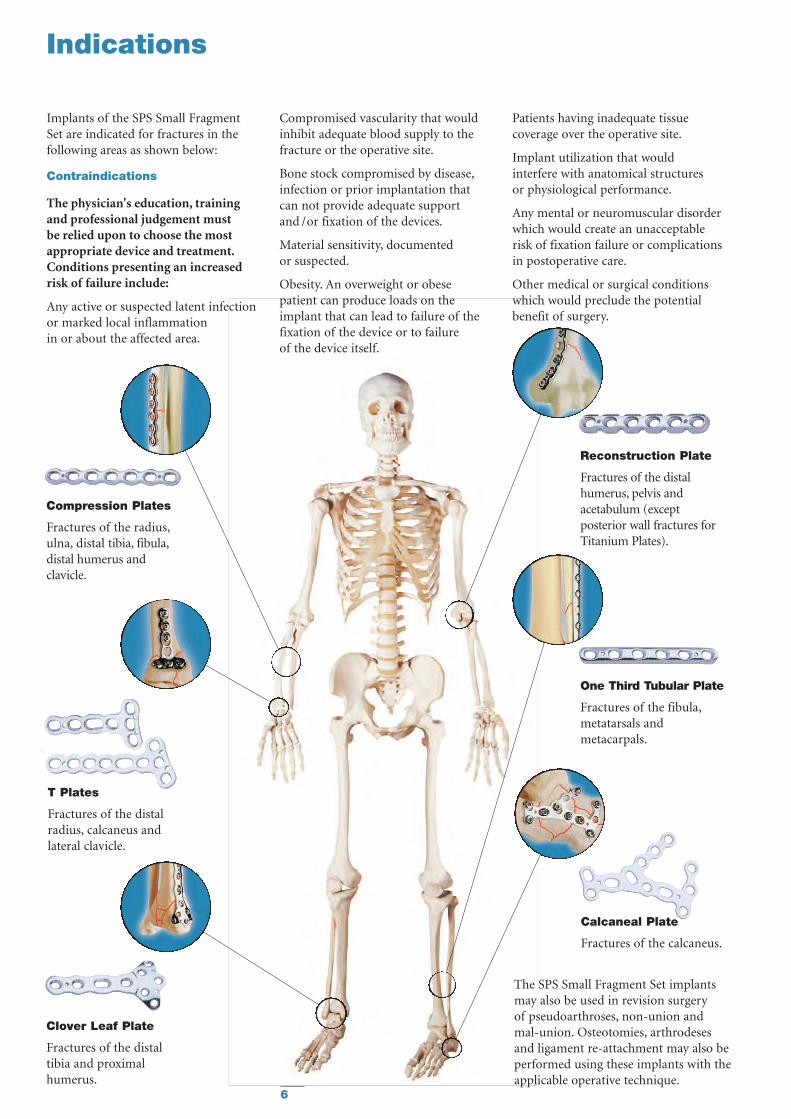
Indications
The SPS Small Fragment Set implantsmay also be used in revision surgery of pseudoarthroses, non-union and mal-union. Osteotomies, arthrodeses and ligament re-attachment may also beperformed using these implants with theapplicable operative technique.
Reconstruction Plate
Fractures of the distalhumerus, pelvis andacetabulum (exceptposterior wall fractures forTitanium Plates).
Clover Leaf Plate
Fractures of the distaltibia and proximalhumerus.
Calcaneal Plate
Fractures of the calcaneus.
One Third Tubular Plate
Fractures of the fibula,metatarsals andmetacarpals.
T Plates
Fractures of the distalradius, calcaneus andlateral clavicle.
Implants of the SPS Small FragmentSet are indicated for fractures in thefollowing areas as shown below:
Contraindications
The physician's education, trainingand professional judgement must be relied upon to choose the mostappropriate device and treatment.Conditions presenting an increasedrisk of failure include:
Any active or suspected latent infectionor marked local inflammation in or about the affected area.
Compromised vascularity that wouldinhibit adequate blood supply to thefracture or the operative site.
Bone stock compromised by disease,infection or prior implantation thatcan not provide adequate support and /or fixation of the devices.
Material sensitivity, documented or suspected.
Obesity. An overweight or obesepatient can produce loads on theimplant that can lead to failure of thefixation of the device or to failure of the device itself.
Patients having inadequate tissuecoverage over the operative site.
Implant utilization that wouldinterfere with anatomical structures or physiological performance.
Any mental or neuromuscular disorderwhich would create an unacceptablerisk of fixation failure or complicationsin postoperative care.
Other medical or surgical conditionswhich would preclude the potentialbenefit of surgery.
Compression Plates
Fractures of the radius,ulna, distal tibia, fibula,distal humerus andclavicle.

7
Independent Interfragmentary Compression
When the thread of a screw only takespurchase in the far cortex of the bone,this is known as a Lag-Screw.The screw thread takes no purchase in the near cortex of the bone eitherbecause the screw shaft has no threador the drill hole in the near cortex is equal or greater than the outsidediameter of the screw (the near cortexhas to be overdrilled therefore to createa “gliding” hole). This will ensure that the screw thread will only takepurchase in the area leading to the far cortex or “threaded” hole.
When such a screw is inserted andtightened, it causes the two fragmentsof bone to be compressed.
Often independent interfragmentaryLag-Screws are used in conjunctionwith Plating fixation.
When a Lag-Screw is inserted at rightangles to the fracture line this providesa maximum of interfragmentalcompression but a minimum of axialstability. The loss of reduction andfixation will occur when the twofragments start to glide on each otherunder axial load. It is often preferredtherefore, when using multiple screwsto insert one at right angles to the axisof the bone and the others at rightangles to the fracture line.
In this spiral fracture, which is fixed using multiple screws, the central screw is at90° to the long axis of the bone and will ensure axial stability. The other screws areat right angles to the spiral fracture line and will ensure optimal compression.
The chart above highlights the corresponding drill and screw diameters required to ensure interfragmentary Lag Screw compression.
Thread Diameter
Screw Type
Thread Length
Drill BitGliding Hole
2.7 3.5 -/- 4.5 4.5/4.5/-
Drill BitThreaded Hole
2.0 2.5 2.5 3.2 3.2
Tap (2.7) (3.5) 4.0 (4.5) 6.5
full full partial/full full 16/32/full
corticalself-tapping
corticalself-tapping
cancellousnon-self-tapping
cancellousnon-self-tapping
corticalself-tapping
2.7 3.5 4.0 4.5 6.5
In situations where space is restrictiveit may be advantageous to more evenly distribute the load using three 2.7mm screws as opposed to two 3.5mm screws. For this purpose2.7mm screws have been added to theSPS Small Fragment Set.
PLEASE NOTE THAT DUE TO THESMALLER HEAD DIAMETER,THE 2.7MM SCREWS CAN NOT BEUSED FOR PLATE FIXATION.
Operative Technique
8
The Modular Drill Guide
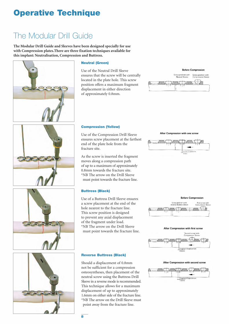
Compression (Yellow)
Use of the Compression Drill Sleeveensures screw placement at the farthestend of the plate hole from the fracture site.
As the screw is inserted the fragmentmoves along a compression path of up to a maximum of approximately0.8mm towards the fracture site.*NB The arrow on the Drill Sleevemust point towards the fracture line.
Buttress (Black)
Use of a Buttress Drill Sleeve ensures a screw placement at the end of thehole nearest to the fracture line.This screw position is designed to prevent any axial displacement of the fragment under load.*NB The arrow on the Drill Sleevemust point towards the fracture line.
Reverse Buttress (Black)
Should a displacement of 0.8mm not be sufficient for a compressionosteosyntheses, then placement of theneutral screw using the Buttress DrillSleeve in a reverse mode is recommended.This technique allows for a maximumdisplacement of up to approximately1.6mm on either side of the fracture line.*NB The arrow on the Drill Sleeve mustpoint away from the fracture line.
The Modular Drill Guide and Sleeves have been designed specially for use with Compression plates.There are three fixation techniques available for this implant: Neutralisation, Compression and Buttress.
Neutral (Green)
Use of the Neutral Drill Sleeve ensures that the screw will be centrally located in the plate hole. This screwposition offers a maximum fragmentdisplacement in either direction of approximately 0.8mm.
Operative Technique
9
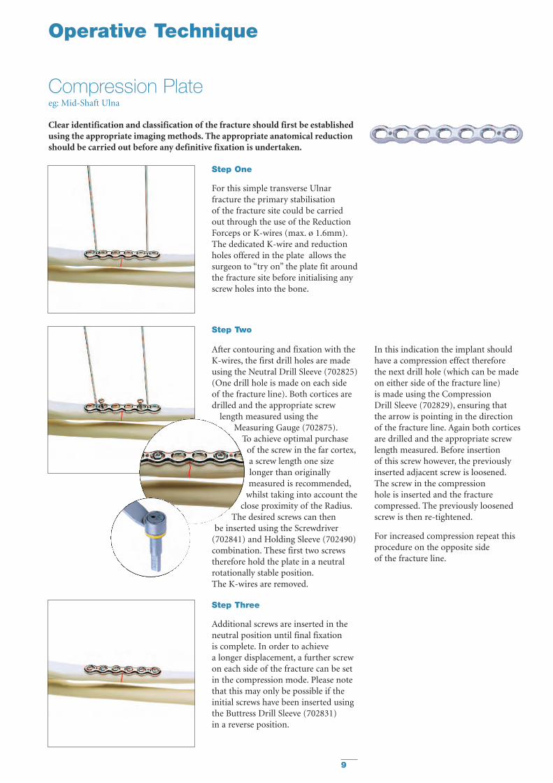
Clear identification and classification of the fracture should first be establishedusing the appropriate imaging methods. The appropriate anatomical reductionshould be carried out before any definitive fixation is undertaken.
Step One
For this simple transverse Ulnarfracture the primary stabilisation of the fracture site could be carried out through the use of the ReductionForceps or K-wires (max. ø 1.6mm).The dedicated K-wire and reductionholes offered in the plate allows thesurgeon to “try on” the plate fit aroundthe fracture site before initialising anyscrew holes into the bone.
After contouring and fixation with theK-wires, the first drill holes are madeusing the Neutral Drill Sleeve (702825)(One drill hole is made on each side of the fracture line). Both cortices aredrilled and the appropriate screw
length measured using theMeasuring Gauge (702875).
To achieve optimal purchase of the screw in the far cortex,a screw length one sizelonger than originallymeasured is recommended,
whilst taking into account theclose proximity of the Radius.
The desired screws can then be inserted using the Screwdriver
(702841) and Holding Sleeve (702490)combination. These first two screwstherefore hold the plate in a neutralrotationally stable position.The K-wires are removed.
In this indication the implant shouldhave a compression effect therefore the next drill hole (which can be madeon either side of the fracture line) is made using the Compression Drill Sleeve (702829), ensuring that the arrow is pointing in the directionof the fracture line. Again both corticesare drilled and the appropriate screwlength measured. Before insertion of this screw however, the previouslyinserted adjacent screw is loosened.The screw in the compression hole is inserted and the fracturecompressed. The previously loosenedscrew is then re-tightened.
For increased compression repeat thisprocedure on the opposite side of the fracture line.
Step Three
Additional screws are inserted in theneutral position until final fixation is complete. In order to achieve a longer displacement, a further screwon each side of the fracture can be setin the compression mode. Please notethat this may only be possible if theinitial screws have been inserted usingthe Buttress Drill Sleeve (702831) in a reverse position.
Step Two
Operative Technique
Compression Plateeg: Mid-Shaft Ulna

10
Step Two
Operative Technique
Step One
For this distal Humeral fracture,reduction and primary stabilisation of the fracture site could first be carriedout through either the use of independentK-wires (max. ø 1.6mm) andReduction Forceps or through thededicated K-wire and reduction holesoffered in the plate. This allows thesurgeon to “try on” the plate fit aroundthe fracture site before initialising anyscrew holes into the bone.
After contouring and affixing the platewith the K-wires the first neutral drillholes are made using the Double DrillGuide (702418) together with the2.5mm Drill. (One drill hole is madeon each side of the fracture site).To achieve optimal purchase of the
screw in the far cortex, a screwlength one size longer than
originally measured isrecommended (this plate,like all plates in the SPSSmall Fragment Set offersthe opportunity to use
4.0mm cancellous screws rather thancortical screws). The desired screws canthen be inserted using the Screwdriver(702841) and Holding Sleeve (702490)combination. These screws hold the plate in a neutral position.Depending on the fracture pattern itmay be advisable to insert a Lag-Screwthrough the plate for incresed stability.
Step Three
Additional screws are added in theneutral, compression or buttressposition until final fixation is complete.
Certain indications may require screwangulation through the plate whichcan be easily achieved when using theDouble Drill Guide (702418).
Note: Titanium Recon plate bendinglimitations, see page 18“Plate Bending”
Clear identification and classification of the fracture should first be establishedusing the appropriate imaging methods. The appropriate anatomical reductionshould be carried out before any definitive fixation is undertaken.
Reconstruction Plateeg: Distal Humerus
11
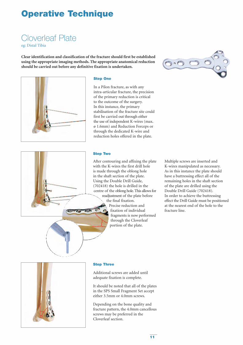
Step Two
After contouring and affixing the platewith the K-wires the first drill hole is made through the oblong hole in the shaft section of the plate.Using the Double Drill Guide,(702418) the hole is drilled in thecentre of the oblong hole. This allows for
readjustment of the plate beforethe final fixation.
Precise reduction andfixation of individualfragments is now performedthrough the Cloverleafportion of the plate.
Multiple screws are inserted and K-wires manipulated as necessary.As in this instance the plate shouldhave a buttressing effect all of theremaining holes in the shaft sectionof the plate are drilled using theDouble Drill Guide (702418).In order to achieve the buttressingeffect the Drill Guide must be positionedat the nearest end of the hole to thefracture line.
Clear identification and classification of the fracture should first be establishedusing the appropriate imaging methods. The appropriate anatomical reductionshould be carried out before any definitive fixation is undertaken.
Step One
In a Pilon fracture, as with any intra-articular fracture, the precisionof the primary reduction is critical to the outcome of the surgery.In this instance, the primarystabilisation of the fracture site couldfirst be carried out through either the use of independent K-wires (max.ø 1.6mm) and Reduction Forceps orthrough the dedicated K-wire andreduction holes offered in the plate.
Step Three
Additional screws are added untiladequate fixation is complete.
It should be noted that all of the platesin the SPS Small Fragment Set accepteither 3.5mm or 4.0mm screws.
Depending on the bone quality andfracture pattern, the 4.0mm cancellousscrews may be preferred in theCloverleaf section.
Operative Technique
Cloverleaf Plateeg: Distal Tibia

12
Operative Technique
T-Plate
In this plate the oblong hole allows the plate to be readjusted before final tightening. The bi-directionalcompression holes offer not only axialcompression but compression acrossthe T-section, for articular reduction.
Oblique T-Plate
This plate offers the same options asthe standard T-plate. The 20° offsetangle of the head of this plate additionallyoffers a more anatomic fit along theRadial Styloid.
This plate is primarily a neutralisationimplant. However, eccentric placement of screws will result in limited axialcompression. The plate hole collarsmaximise stability and eliminate thepossible penetration of the screwheadinto the near cortex thus preserving thescrews’ fixation.
The equal hole spacing in this plateallows it’s application to a variety offracture patterns without assuming thefracture location in relation to a ‘gap’in the plate.
Calcaneal Plate
This low profile, anatomically shapedplate design allows contouring to eitherthe left or right Calcaneus.The combination of oblong and round holes ensures adequate fixation,increased strength and screw angulationin the critical central area.
This area has also been strengthened for improved durability.2.7mm screws can be used in the roundholes offering a very low profile fixation.
One-Third Tubular Plate
13
Technical Details
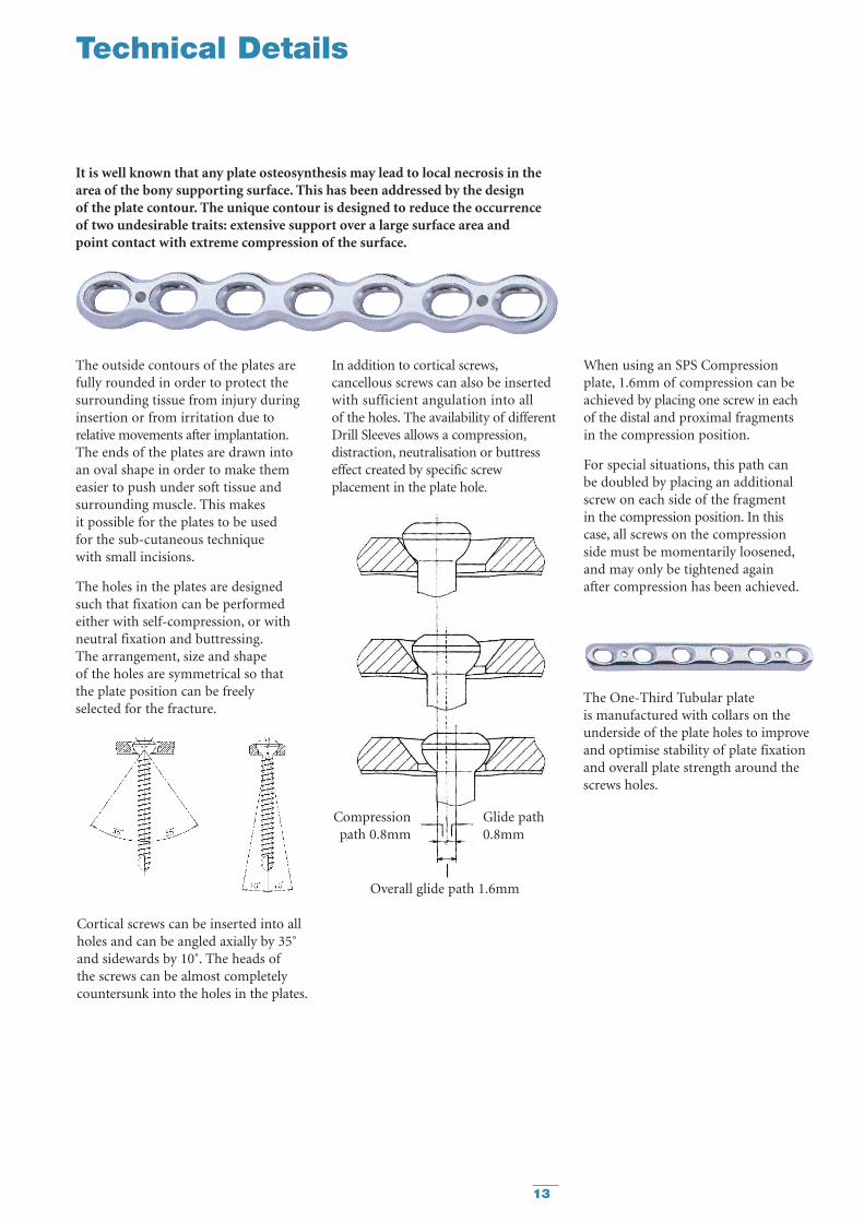
It is well known that any plate osteosynthesis may lead to local necrosis in thearea of the bony supporting surface. This has been addressed by the design of the plate contour. The unique contour is designed to reduce the occurrence of two undesirable traits: extensive support over a large surface area and point contact with extreme compression of the surface.
The outside contours of the plates arefully rounded in order to protect thesurrounding tissue from injury duringinsertion or from irritation due torelative movements after implantation.The ends of the plates are drawn intoan oval shape in order to make themeasier to push under soft tissue andsurrounding muscle. This makes it possible for the plates to be used for the sub-cutaneous technique with small incisions.
The holes in the plates are designedsuch that fixation can be performedeither with self-compression, or withneutral fixation and buttressing.The arrangement, size and shape of the holes are symmetrical so thatthe plate position can be freely selected for the fracture.
Cortical screws can be inserted into allholes and can be angled axially by 35˚and sidewards by 10˚. The heads ofthe screws can be almost completelycountersunk into the holes in the plates.
When using an SPS Compressionplate, 1.6mm of compression can beachieved by placing one screw in eachof the distal and proximal fragments in the compression position.
For special situations, this path can be doubled by placing an additionalscrew on each side of the fragment in the compression position. In this case, all screws on the compression side must be momentarily loosened,and may only be tightened again after compression has been achieved.
Overall glide path 1.6mm
Compression Glide pathpath 0.8mm 0.8mm
The One-Third Tubular plate is manufactured with collars on theunderside of the plate holes to improveand optimise stability of plate fixationand overall plate strength around thescrews holes.
In addition to cortical screws,cancellous screws can also be insertedwith sufficient angulation into all of the holes. The availability of differentDrill Sleeves allows a compression,distraction, neutralisation or buttresseffect created by specific screwplacement in the plate hole.

14
Ordering Information – Plates
4 Recommended set item
Stainless Plate Holes TitaniumSteel Length REFREF mm
430202 25 2 621122430203 38 3 621123430204 51 4 4 621124430205 64 5 4 621125430206 77 6 4 621126430207 90 7 4 621127430208 103 8 4 621128430209 116 9 621129430210 129 10 621130430211 142 11 621131430212 155 12 621132430213 168 13 621133430214 181 14 621134
Stainless Plate Holes TitaniumSteel Length REFREF mm
430002 26 2 621142430003 39 3 621143430004 52 4 4 621144430005 65 5 4 621145430006 78 6 4 621146430007 91 7 4 621147430008 104 8 4 621148430009 117 9 621149430010 130 10 4 621150430011 143 11 621151430012 156 12 621152430014 182 14 621154430016 208 16 621156430018 234 18 621158430020 260 20 621160
Stainless Plate Holes TitaniumSteel Length REFREF mm
430052 26 2 N/A430053 39 3 N/A430054 52 4 N/A430055 65 5 N/A430056 78 6 N/A430057 91 7 N/A430058 104 8 N/A430059 117 9 N/A430060 130 10 N/A430061 143 11 N/A430062 156 12 N/A430064 182 14 N/A430066 208 16 N/A430068 234 18 N/A430070 260 20 N/A
Stainless Plate Holes Plate TitaniumSteel Length Length REFREF StSt mm Ti mm
430104 48 4 4 54 621174S430105 60 5 4 66 621175S430106 72 6 4 78 621176S430107 84 74 90 621177S430108 96 8 4 102 621178S430109 108 9 114 621179S430110 120 104 126 621180S
N/A N/A 11 138 621181S430112 144 12 150 621182S430114 168 14 N/A N/A430116 192 16 N/A N/A430118 216 18 N/A N/A430120 240 20 N/A N/A430122 264 22 N/A N/A
Stainless Plate Holes TitaniumSteel Length Shaft Head REFREF mm
431023 40 3 3 4 621423431024 49 4 3 4 621424431025 57 5 3 621425431026 66 6 3 4 621426431028 83 8 3 621428431030 100 10 3 621430431034 51 4 4 4 621434431036 68 6 4 621436
Stainless Plate Holes TitaniumSteel Length Shaft REFREF mm
431003 45 3 4 621463431004 53 4 4 621464431005 62 5 621465431006 70 6 4 621466431008 88 8 621468
Stainless Length TitaniumSteel mm REFREF
431102 50 621552431103 60 4 621553431104 70 4 621554431105 80 621555
Stainless Plate Holes TitaniumSteel Length REFREF mm
431043 66 3 4 621443431044 80 4 4 621444431045 94 5 621445431046 109 6 4 621446431048 138 8 621448431050 167 10 621450
Stainless Diameter Length TitaniumSteel mm mm REFREF
390142 1.0 150 690015390157 1.25 4 150 690020390162 1.4 150 N/A390164 1.6 4 150 690030390192 2.0 4 150 690035
Stainless Diameter Thickness TitaniumSteel mm mm REFREF
390018 7.0 4 0.8 619905390019 9.0 4 1.0 619909
One Third Tubular Plate with Collars
Waisted Compression Plate
Recon Plate
T-Plate
Oblique T-Plate
Calcaneal Plate
K-Wires with trocar tip - (PKG 10)
Cloverleaf Plate
Washer
Standard Compression Plate
For sterile Implants add “S” to the REF

15
4 Recommended set item
For full range of standard non-selftapping screws please refer to the Stryker® Trauma Product Catalogue.
Stainless Steel Screw TitaniumREF Length mm REF
338610 10 4 603010338612 12 4 603012338614 14 4 603014338616 16 4 603016338618 18 4 603018338620 20 4 603020338622 22 4 603022338624 24 4 603024338626 26 4 603026338628 28 4 603028338630 30 4 603030338632 32 4 603032338634 34 4 603034338636 36 4 603036338638 38 4 603038338640 40 4 603040338642 42 4 603042338644 44 4 603044338645 45 603045338646 46 4 603046338648 48 4 603048338650 50 4 603050338655 55 4 603055338660 60 4 603060338665 65 N/A338670 70 N/A338675 75 N/A338680 80 N/A338685 85 N/A338690 90 N/A338695 95 N/A338700 100 N/A338705 105 N/A338710 110 N/A338715 115 N/A338720 120 N/A
Stainless Steel Screw TitaniumREF Length mm REF
349608 8 605008349610 10 605010349612 12 605012349614 14 605014349616 16 605016349618 18 605018349620 20 605020349622 22 605022349624 24 605024349626 26 605026349628 28 605028349630 30 605030349632 32 605032349634 34 605034349636 36 605036349638 38 605038349640 40 605040349645 45 605045349650 50 605050349655 55 605055349660 60 605060
Due to the smaller head diameter,the 2.7mm screws cannot be used for plate fixation.
Ordering Information – Screws
Stainless Steel Screw TitaniumREF Length mm REF
345510 10 4 604210345512 12 4 604212345514 14 4 604214345516 16 4 604216345518 18 4 604218345520 20 4 604220345522 22 4 604222345524 24 4 604224345526 26 4 604226345528 28 4 604228345530 30 4 604230345532 32 4 604232345534 34 4 604234345535 35 604235345536 36 4 604236345538 38 4 604238345540 40 4 604240345545 45 4 604245345550 50 4 604250345555 55 4 604255345560 60 4 604260345565 65 604265345570 70 604270345575 75 604275345580 80 604280345585 85 604285345590 90 604290345595 95 604295345600 100 604300
Stainless Steel Screw TitaniumREF Length mm REF
345410 10 4 604010345412 12 4 604012345414 14 4 604014345416 16 4 604016345418 18 4 604018345420 20 4 604020345422 22 4 604022345424 24 4 604024345426 26 4 604026345428 28 4 604028345430 30 4 604030345432 32 4 604032345434 34 4 604034345435 35 604035345436 36 4 604036345438 38 4 604038345440 40 4 604040345445 45 4 604045345450 50 4 604050345455 55 4 604055345460 60 4 604060345465 65 604065345470 70 604070345475 75 604075345480 80 604080345485 85 604085345490 90 604090345495 95 604095345500 100 604100
3.5mm Cortical Screw, Self Tapping 4.0mm Cancellous Screw, Partial Thread
4.0mm Cancellous Screw, Full Thread
2.7mm Cortical Screw, Self Tapping
For sterile Implants add “S” to the REF
16
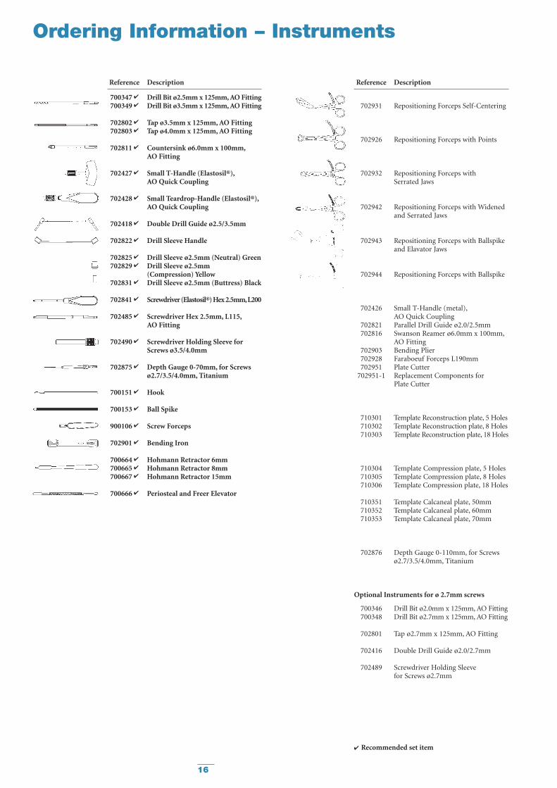
Reference Description
700347 4 Drill Bit ø2.5mm x 125mm, AO Fitting700349 4 Drill Bit ø3.5mm x 125mm, AO Fitting
702802 4 Tap ø3.5mm x 125mm, AO Fitting702803 4 Tap ø4.0mm x 125mm, AO Fitting
702811 4 Countersink ø6.0mm x 100mm,AO Fitting
702427 4 Small T-Handle (Elastosil®),AO Quick Coupling
702428 4 Small Teardrop-Handle (Elastosil®),AO Quick Coupling
702418 4 Double Drill Guide ø2.5/3.5mm
702822 4 Drill Sleeve Handle
702825 4 Drill Sleeve ø2.5mm (Neutral) Green702829 4 Drill Sleeve ø2.5mm
(Compression) Yellow702831 4 Drill Sleeve ø2.5mm (Buttress) Black
702841 4 Screwdriver (Elastosil®) Hex 2.5mm,L200
702485 4 Screwdriver Hex 2.5mm, L115,AO Fitting
702490 4 Screwdriver Holding Sleeve forScrews ø3.5/4.0mm
702875 4 Depth Gauge 0-70mm, for Screwsø2.7/3.5/4.0mm, Titanium
700151 4 Hook
700153 4 Ball Spike
900106 4 Screw Forceps
702901 4 Bending Iron
700664 4 Hohmann Retractor 6mm700665 4 Hohmann Retractor 8mm700667 4 Hohmann Retractor 15mm
700666 4 Periosteal and Freer Elevator
Reference Description
702931 Repositioning Forceps Self-Centering
702926 Repositioning Forceps with Points
702932 Repositioning Forceps withSerrated Jaws
702942 Repositioning Forceps with Widened and Serrated Jaws
702943 Repositioning Forceps with Ballspikeand Elavator Jaws
702944 Repositioning Forceps with Ballspike
702426 Small T-Handle (metal),AO Quick Coupling
702821 Parallel Drill Guide ø2.0/2.5mm702816 Swanson Reamer ø6.0mm x 100mm,
AO Fitting702903 Bending Plier702928 Faraboeuf Forceps L190mm702951 Plate Cutter
702951-1 Replacement Components for Plate Cutter
710301 Template Reconstruction plate, 5 Holes710302 Template Reconstruction plate, 8 Holes710303 Template Reconstruction plate, 18 Holes
710304 Template Compression plate, 5 Holes710305 Template Compression plate, 8 Holes710306 Template Compression plate, 18 Holes
710351 Template Calcaneal plate, 50mm710352 Template Calcaneal plate, 60mm710353 Template Calcaneal plate, 70mm
702876 Depth Gauge 0-110mm, for Screwsø2.7/3.5/4.0mm, Titanium
Optional Instruments for ø 2.7mm screws
700346 Drill Bit ø2.0mm x 125mm, AO Fitting700348 Drill Bit ø2.7mm x 125mm, AO Fitting
702801 Tap ø2.7mm x 125mm, AO Fitting
702416 Double Drill Guide ø2.0/2.7mm
702489 Screwdriver Holding Sleevefor Screws ø2.7mm
Ordering Information – Instruments
4 Recommended set item
17
4 Recommended set item
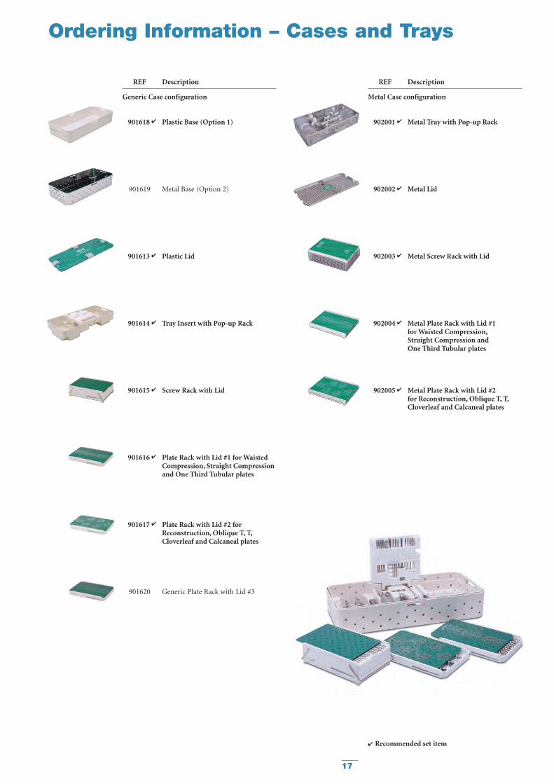
REF Description
Generic Case configuration
901618 4 Plastic Base (Option 1)
901619 Metal Base (Option 2)
901613 4 Plastic Lid
901614 4 Tray Insert with Pop-up Rack
901615 4 Screw Rack with Lid
901616 4 Plate Rack with Lid #1 for Waisted Compression, Straight Compression and One Third Tubular plates
901617 4 Plate Rack with Lid #2 forReconstruction, Oblique T, T,Cloverleaf and Calcaneal plates
901620 Generic Plate Rack with Lid #3
REF Description
Metal Case configuration
902001 4 Metal Tray with Pop-up Rack
902002 4 Metal Lid
902003 4 Metal Screw Rack with Lid
902004 4 Metal Plate Rack with Lid #1for Waisted Compression,Straight Compression and One Third Tubular plates
902005 4 Metal Plate Rack with Lid #2for Reconstruction, Oblique T, T,Cloverleaf and Calcaneal plates
Ordering Information – Cases and Trays

18
Picture 3
Picture 6Picture 4
Picture 7
Picture 1
Picture 5
Picture 2
Additional Information
Plate Bending
There are three types of plate curvatures that are often used to best match the anatomy of different bones within the body.
• A bend along the main plate axis as shown in pictures 1 and 6.• Twisted along the main plate axis as shown is pictures 2 and 3.• A bend ‘on the flat’ to adapt to the long axis of the bone,
as shown in pictures 4 and 7.
The bending irons (702901) includedin the SPS Small Fragment Set havecustom sized slots to accommodate thebending and twisting of various plateswithin the set.
Manipulation of the implants isachieved by inserting the relevantplates into the appropriate slot andthen using the irons to form the plateto the required anatomical fit as shownin the various pictures above and left.
An additional small slot at the tip of both bending irons facilitatesnecessary contouring of the T, Cloverleafand Calcaneal plates (see picture 5).
An optional bending plier (702903)can be used to facilitate contouring of the reconstruction plates only(pictures 6 and 7).
Generally, a maximum bend of 20° ispossible between each set of holes.However, shaping of the most distalhole of the plate for distal medialhumeral fractures often requires abend up to 35°. This bend is permitted
due to the fact that it is a positivebend, i.e. through the cross-sectionalconcavity of the plate as shown.Backbending, repetitive or multiplebending attempts will weaken the plateto the point of breakage.
Bending specifications for Titanium Recon Platesnegative bending max. 20°
positive bending max. 35°
18

19
Additional Information
Matta Pelvic System
Basic Fragment Set
The implants include a new, speciallydesigned MPS Symphysis plate with an increased plate width through themidsection – this unique plate offersClinicians new options when treatingSymphysis Pubis Disruptions.
The implants also includedifferentiated curved radius 88mm or 108mm plates designed to respectboth the Female and Male anatomiesas well as a more malleable MPS Flexplate which allows easier threedimensional contouring.
All the plates are fully compatible with a wide range of 3.5mm and4.5mm cortical screws. In addition,the 6.5mm screws included,make the Implant Set the mostcomprehensive on the market.
The Instrument and ReductionForceps have been simplified to betterassist the Clinician in what is an alreadycomplicated procedure. The Instrumentscan be easily handled and manoeuvredaround the anatomy without anyvisual restriction. Additional ReductionForceps like the 3.5mm Jungbluth areunique and epitomise the innovationand practicality of this System.
Featuring:
3.5mm cortical screws – self tapping
4.5mm cortical screws – self tapping
6.5mm cancellous screws – 16mm thread
6.5mm cancellous screws – 32mm thread
MPS Symphysis plate
MPS Flex plate (annealed)
MPS Straight plate
MPS Curved R108 plate
MPS Curved R88 plate
Modular Case design
Drill, Taps, Countersink – AO couplings
2 Depth Gauges – (for 3.5mm and 4.5/6.5mm Screws)
Fixed Angle Drill Guides
Elastosil® Handles on all fixed handle instruments
Reduction Pins
Spiked Disks and Ball Spike Pushers
Screw Holding Sleeves
Bending Irons and Templates
Bending Plier
Unique Repositioning Forceps
Sciatic Nerve Retractors
A new selection of seven plates,each featuring K-wire and reductionholes–for improved primarystabilisation; rounded plate ends – to facilitate the option of subcutaneousplate insertion; uniform hole spacingwith bi-directional holes offeringincreased screw angulation; as well as the unique outer plate contouringare all features of the implant set.
A comprehensive screw range is enhanced by a self-cutting design.A full range of instrumentation is complemented by the unique rangeof reduction clamps and forceps.These non-standardised instrumentsoffer the Clinician new possibilities in their approach to large-bonefracture reduction and fixation.
Featuring:
Modular Case design
4.5mm cortical screws – self tapping
6.5mm cancellous screws – 16mm thread
6.5mm cancellous screws – 32mm thread
6.5mm cancellous screws – Full thread
Drill, Taps, Countersink – AO couplings
2 Diameters of K-wires
Modular and Fixed Angle Drill Guides
Compression plate – Broad
Compression plate – Narrow
T-plate
T-Buttress plate
L-Buttress plate
Reconstruction plate
Elastosil® Handles on all fixed handleinstruments
Combined Hook and Ball Spike
Combined Periosteal and Freer Elevator
Hohmann Retractors
Bending Irons and Templates
Optional Table Plate Bender Plier
Forceps
Designed by Joel M. Matta, M.D. the Matta Pelvic System, with four modular trays,features the latest innovations in Pelvic implants and instrumentation.
This System offers Clinicians multiple options for the most commontreatments of long–bone fractures.
Other Stryker Plating Systems

The information presented in this brochure is intended to demonstrate a Stryker product. Always refer to the packageinsert, product label and/or user instructions before using any Stryker product. Surgeons must always rely on their ownclinical judgment when deciding which products and techniques to use with their patients. Products may not be availablein all markets. Product availability is subject to the regulatory or medical practices that govern individual markets. Pleasecontact your Stryker representative if you have questions about the availability of Stryker products in your area.
Stryker Corporation or its subsidiary owns the registered trademark: Stryker.Wacker-Chemie GmbH owns the following trademark: Elastosil
Literature Number: 982181LOT C0107
Copyright © 2007 StrykerPrinted in Switzerland
Biologics
Surgical Products
Neuro & ENT
Trauma, Extremities & Deformities
Biologics
Surgical Products
Neuro & ENT
Trauma, Extremities & Deformities
Stryker Trauma AGBohnackerweg 1CH-2545 SelzachSwitzerland
www.osteosynthesis.stryker.com