SPRAY DRYER ADL311/ADL311S - files.yamato-net.co.jp · SPRAY DRYER ADL311/ADL311S Instruction...
48
SPRAY DRYER ADL311/ADL311S Instruction Manual - Version 3 - ● Thank you for purchasing "Spray Dryer, ADL 310" of Yamato Scientific Co., Ltd. ● To use this unit properly, read this "Instruction Manual" thoroughly before using this unit. Keep this instruction manual around this unit for referring at anytime. :WARNING!: Carefully read and thoroughly understand the important warning items described in this manual before using this unit. Yamato Scientific Co. LTD., This paper has been printed on recycled paper.
Transcript of SPRAY DRYER ADL311/ADL311S - files.yamato-net.co.jp · SPRAY DRYER ADL311/ADL311S Instruction...
SPRAY DRYER ADL311/ADL311S
Instruction Manual
- Version 3 -
Thank you for purchasing "Spray Dryer, ADL 310" of Yamato
Scientific Co., Ltd.
To use this unit properly, read this "Instruction Manual" thoroughly before using this unit. Keep this instruction manual around this unit for referring at anytime.
:WARNING!:
Carefully read and thoroughly understand the important warning items described in this manual before using this unit.
Yamato Scientific Co. LTD., This paper has been printed on recycled paper.

Contents 1. Safety precautions.................................................................... 1
Explanation of pictograms ............................................................. 1 List of symbols ....................................................................... 2 Warning・Cautions ................................................................... 3
2. Before using this unit.................................................................. 5 Precautions when installing the unit ..................................................... 5 Service receptacle capacity ............................................................ 8 Temperature output terminal............................................................ 8
3.Names of parts and their function........................................................ 9 Main unit + GF300 set................................................................. 9 Operation panel ..................................................................... 10
4. Operating procedures ................................................................ 11 Preparations ........................................................................ 11 Operating method ................................................................... 15 Related Figure between Blower and Temperature/Drying Air Quantity (Reference) ........... 20
5. Handling Precautions ................................................................ 21 Drying Method under Appropriate Condition ............................................. 22 Caution during operation.............................................................. 23
6. Maintenance Method................................................................. 24 Daily Inspection and Maintenance...................................................... 24
7. Long storage and disposal ............................................................ 26 When not using this unit for long term / When disposing ................................... 26 Matters to consider when disposing of the unit ........................................... 26
8. When a trouble occurs ............................................................... 27 Safety unit and error indications ....................................................... 27 Confirmation and language select for the manual......................................... 28 Trouble Shooting .................................................................... 29
9. After Service and Warranty ........................................................... 31 When requesting a repair ............................................................. 31
10. Specification....................................................................... 32 11. Wiring Diagram .................................................................... 34
ADL311 Wiring Diagram .............................................................. 34 ADL311 SWiring Diagram............................................................. 36
12. System Chart ...................................................................... 38 System Chart ....................................................................... 38
13. Principle of Operation ............................................................... 39 14. Replacement parts table............................................................. 40 15. List of Dangerous Substances........................................................ 43 16. Standard installation manual ......................................................... 44

1
1. Safety precautions Explanation of pictograms
About pictograms
A variety of pictograms are indicated in this operating instruction and on
products for safe operation. Possible results from improper operation
ignoring them are as follows.
Be sure to fully understand the descriptions below before proceeding to the
text.
Warning Caution Indicates a situation which may result in minor injury (Note 2) and
property damages (Note 3.)
(Note 1)Serious injury means a wound, an electrical shock, a bone fracture or intoxication that may
leave after effects or require hospitalization or outpatient visits for a long time.
(Note 2)Minor injury means a wound or an electrical shock that does not require hospitalization or
outpatient visits for a long time.
(Note 3)Property damage means damage to facilities, devices and buildings or other properties.
Meanings of pictograms
This pictogram indicates a matter that encourages the user to adhere to warning (“caution” included). Specific description of warning is indicated near this pictogram. This pictogram indicates prohibitions Specific prohibition is indicated near this pictogram.
This pictogram indicates matters that the user must perform Specific instruction is indicated near this pictogram.
Indicates a situation which may result in death or serious injury (Note 1.)

2
1. Safety precautions List of symbols
Warning
General warnings Danger!: High voltage
Danger!: High temperature
Danger!: Moving part
Danger!: Hazard of explosion
Caution
General cautions Electrical shock! Burning! Caution for no liquid heating!
Caution for water leak!
For water only Poisonous material
Prohibitions
General bans Fire ban Do not disassemble Do not touch
Compulsions
General
compulsions Connect ground
wire Install levelly Pull out the power plug
Regular inspection

3
1. Safety precautions Warning・Cautions
Warning
Do not use this unit in an area where there is flammable or explosive gas
Never use this unit in an area where there is flammable or explosive gas. This unit is not explosion-proof. An arc may be generated when the power switch is turned on or off, and fire/explosion may result. (Refer to page 42 “15. List of Dangerous Substances”.)
Always ground this unit Always ground this unit on the power equipment side in order to avoid electrical shock due to a power surge.
Apply the source of rated power or more Be sure to apply the source of rated power or more. Applying non-rated voltage or non-rated power supply may cause the fire or electric shock.
Prohibition of use for error If a smoke or abnormal smell may be occurred, turn off the power switch of the main unit immediately, and turn off the original power source, and finally contact to either the dealer you purchased this unit or our sales office. Leaving the failure may cause the fire or electric shock. Since the repairing of this unit is dangerous for non-specified service person, never repair the unit by the customer himself.
Do not use the power cord if it is bundled or tangled Do not use the power cord if it is bundled or tangled. If it is used in this manner, it can overheat and fire may be caused.
Do not damage power cord
Do not damage power cord by bending, pulling, or twisting forcedly. It may cause the fire or electric shock. Besides, operating the unit with the something put on the cord may cause overheat, and result in fire.
Never use an explosive or a flammable material with this unit.
Never use an explosive material, a flammable material or a material containing them. An explosion or an electrical shock may result. ADL311S supports organic solvents by connecting it to the optional GAS410. Carefully read the operation manual of GAS410 and take special care for handling of organic solvents. See section “15. List of Dangerous Substances” on page 42.
Never try to touch a hot part. Some parts of the unit are hot during and immediately after operation. Take special care for possible burning.
Never try to disassemble or alter the unit. Never try to disassemble or alter the unit. A malfunction, a fire or an electrical shock may result.

4
1. Safety precautions Warning・Cautions
Caution
During a thunder storm During a thunderstorm, turn off the power key immediately, then turn off the circuit breaker and the main power. If this procedure is not followed, fire or electrical shock may be caused.
• If the electric failure shall be occurred, When power is shut off during operation (while the blower is operating or liquid is being sent) due to turning of the ELB to "OFF" or a power failure, all operation modes will reset to the intial states after recovery. When the temperature inside the chamber has been high, keep operating the blower until it cools down to 45 or below after recovery from a power failure.
• Do not perform unattended operation during activating the unit
Do not perform unattended operation during activating the unit. Since the unit is in idling status and the nozzle is blocked of after the operation using sample, the temperature around outlet is increased and the remaining sample is flown from the sample tube disconnected from the unit, and this failure may cause the indeterminism accident.
About countermeasures against static electricity
The cyclone may charge with static electricity depending on the specifc specimen used, or operating environment or conditions. Implement countermeasures against static electricity such as attaching included earth clips at three positions on the clamp at the connection of the cyclone or attaching an antistatic brush (optional) to the body of the cyclone.

5
2. Before using this unit Precautions when installing the unit
Warning 1. Always ground this unit
・ Be sure to connect the earth wire (the green cable of power cord) to the grounding conductor or ground terminal to prevent accidents caused by electric leakage.
・ This unit requires a single phase 200V power supply (also supports AC220V or AC240V by selecting either of it) (See page 11 (1)) Ask the nearest electrical contractor for the power including the connecting work. The setting (connecting) work is performed following the related electrical equipment technical standard published by the corresponding country to be used this unit.
・ Do not connect the earth wire to gas or water pipes. If not, fire disaster may be caused. ・ Do not connect the earth wire to the ground for telephone wire or lightning conductor. If
not, fire disaster or electric shock may be caused.
・ The power plug is not attached as standard component. Connect the earth correctly adjusting the type of the power equipment of the user.
2. Pay attention to the color of each core wire when connecting the power cord
Core Wire Color
In-house Wiring
Black Voltage Side
White Voltage Side
Be sure to check that the breaker on the power source equipment side is turned "OFF" when connecting power cord without fail. Note that the ADL311 does not attach the power plug as standard component. Select the appropriate power plug and terminal matching to the power capacity of the power source equipment to be connected, and connect them. Green Ground Side
3. Choose a proper place for installation
Do not install this unit in a place where:
Rough or dirty surface. Flammable gas or corrosive gas is generated. Ambient temperature bellow 5 or above 30°C. Ambient temperature fluctuates violently. There is direct sunlight. There is excessive humidity and dust. There is a constant vibration. Place where the water is easy-to-be splashed.
Install this unit on a stable place with the space as shown below.
Green (to ground terminal)
Black (to rated power supply terminal)
White (to rated power supply terminal)
50 or more
Rear side
80 ormore 50 or more
100 or more
Front side
Main unit
Rounded terminal for M5

6
Before using this unit Precautions when installing the unit
Warning 4. Do not use this unit in an area where there is flammable or explosive gas
• Never use this unit in an area where there is flammable or explosive gas. This unit is not explosion-proof. An arc may be generated when the power switch is turned ON or OFF, and fire/explosion may result.
Refer to page 42 “15. List of Dangerous Substances”.
可燃性ガス
爆発性ガス
5. Do not use explosive or flammable substances
Never use explosive substances, flammable substances and substances that include explosive or flammable ingredients in this unit. Explosion or fire may occur. ADL311S supports organic solvents by connecting it to the optional GAS410. Carefully read the operation manual of GAS410 and take special care for handling of organic solvents. Refer to page 42 “15. List of Dangerous Substances”.
可燃性物質
爆発性物質
Explosive gas
Flammable gas
Explosive substance
Flammablesubstance

7
2. Before using this unit Precautions when installing the unit
Warning 6. Do not modify 7. Do not topple or tilt this unit
Modification of this unit is strictly prohibited. This could cause a failure.
Set this unit to the flattest place. Setting this unit on rough or slope place could cause the vibration or noise, or cause the unrespectable trouble or malfunction.
改造
8. Use specified receptacle for power source
Choose a correct power distribution board or receptacle that meets the unit’s rated electric capacity.
Electric capacity: AC200V Single phase 16A (AC220V Single phase 17A, AC240V Single phase 18A)
The specification has set to 200V at the time of factory shipping. If you want to switch to AC220V or AC240V power supply, first change the terminal position in the unit before connecting a power supply. (See " Before Using this unit " on P.11) There could be the case that the unit does not run even after turning ON the power. Inspect whether the voltage of the main power is lowered than the specified value, or whether other device(s) uses the same power line of this unit. If the phenomena might be found, change the power line of this unit to the other power line. For connecting of the device to the power source, ask the dealer that you purchased this unit from or an electrical contractor for safe.
9. Handling of power code
Do not entangle the power cord. This will cause overheating and possibly a fire. Do not bend or twist the power cord, or apply excessive tension to it. This may cause a fire and electrical shock. Do not lay the power cord under a desk or chair, and do not allow it to be pinched in order to prevent it from being damaged and to avoid a fire or electrical shock. Keep the power cord away from any heating equipment such as a room heater. The cord's insulation may melt and cause a fire or electrical shock. If the power cord becomes damaged (wiring exposed, breakage, etc.), immediately turn off the power at the rear of this unit and shut off the main supply power. Then contact your nearest dealer for replacement of the power cord. Leaving it may cause a fire or electrical shock. Connect the power plug to the receptacle which is supplied appropriate power and voltage.
Modification
8
2. Before using this unit Service receptacle capacity
Service receptacle capacity
Apply the 100V 2A or less service receptacle for this unit. Connecting the service receptacle with its capacity over 2A blowouts the fuse, and the power source to the service receptacle is shut down. For resetting this damage, replace the fuse in the fuse holder on the right side of the back of the unit. Applicable models Mag mixer: MA series, M-21, MD series, MC800, MF800 Laboratory stirrer: LT series, LR series, LS series Use a separate power supply for a unit with a heater and its total current exceeds 2A
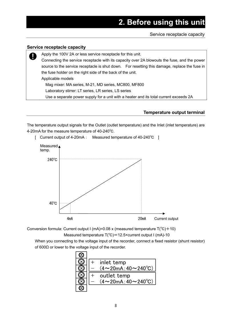
Temperature output terminal The temperature output signals for the Outlet (outlet temperature) and the Inlet (inlet temperature) are 4-20mA for the measure temperature of 40-240. [ Current output of 4-20mA: Measured temperature of 40-240 ] Conversion formula: Current output I (mA)=0.08 x (measured temperature T()+10) Measured temperature T()=12.5×current output I (mA)-10 When you connecting to the voltage input of the recorder, connect a fixed resistor (shunt resistor)
of 600Ω or lower to the voltage input of the recorder.
+ inlet temp- (4~20mA:40~240)+ outlet temp- (4~20mA:40~240)
20mA 4mA
40
240
Measured temp.
Current output

9
3.Names of parts and their function Main unit + GF300 set
Front side
Rear side
Operation panel
Specimen table
Specimen sending
Connector for GAS410 (optional)
*For ADL311S only
Drying chamber
ELB with over current protector
Power cord
Exhaust port (φ51)
Cap
Blind plate for connecting GAS410 (optional) *For ADL311S only
Spray nozzle Air spray tube
Outlet temperature sensor
Stage UP/DOWN handle (inside the door)
For blind plate for recorder (optional)
Blower (inside the door)
GAS410 (optional) connecting nipple
*For ADL311S only
Temperature output terminal
Fuse for service outlet
Service outlet AC100V 2A
Cooling water nozzle port O.D.:φ10.5
Pressurized air inlet O.D.:φ7
Product collecting container
Cyclone
For blind plate for air amount meter (optional)
Nozzle detection sensor BOX *For ADL311S only
Suction port cover
Caster

10
3.Names of parts and their functions Operation panel
No. Name Operation/action ① Power switch This is used to turn power ON/OFF. ② Blower control dial This is used to set an air amount. ③ Key panel
(Touch panel) This is used to perform the operations below and display.
Blower ON/OFF, liquid pump FORWARD/REVERSE Heater ON/OFF, pulse jet switch, error indication
④ Control selector switch Set temperature on the temperature controller on the selected side is used to control the temperature.
⑤ Setting and display of inlet temperature
This is used to set an outlet temperature, display the measured temperature and as an overheat preventive device.
⑥ Setting and display of inlet temperature
This is used to set an inlet temperature, display the measured temperature and as an overheat preventive device.
⑦ Pressure meter This meter indicates the pressure of pressurized air. ⑧ Needle valve control dial This dial is used to control pressure of pressurized air. ⑨ Liquid sending speed control
dial This dial is used to control flow of the liquid pump.
①
②
④
⑦
③
⑤
⑨
⑧
⑥

11
4. Operating procedures Preparations
(1) Selecting the power supply
First switch the power supply terminal
First check that the switches of the control assembly and the ELB are OFF and then connect the power cord securely to the power supply meeting the specified voltage and current. Ordinary, the unit has been specified to AC200V. Switch the terminals in the unit before connecting the power supply when you are going to use the unit in an AC220V or AC240V district. The terminal block is located inside the door at the front control assembly.
T1RS
240V
220V
200V
0 V
(2) Connecting an earth The power cord of this unit is an earthed 3-core captire cable (VCT) that integrates an earth wire and you must earth the green wire.
電圧側 黒
電圧側 白
接地極
屋内配線 機器
緑
(3) Connection of the exhaust duct
In an environment where hot air or fine particles from the blower are of concern, connect the included exhaust duct to the exhaust port and use a draft chamber to exhaust them to outside.
In-house
Voltage side
Voltage side
Ground side
Black
White
Gree
Unit

12
4. Operating procedures Preparations
(4) Connect the nipple (φ7) at the rear of the upper frame and the compressor or other pressurized
air units with the included pressure-proof hose and then securely tighten it using a hose band. Adjust the discharge pressure of the compressor to be constant (0.3MPa or less) using the pressure reducing valve.
(5) Cooling the spray nozzle
The cooling mechanism for the spray nozzle is pre-installed (nozzle O.D.:φ10.5). When you operate the unit under operating conditions under which the spray nozzle is likely to clog, connect a separate cooling water circulating unit (such as CF300) or to a tap water faucet to allow cooking water circulating.
(6) Open the package of the mini spray attachment (GF300) and check for damages to glass and
other parts or any missing parts. (7) Install the distributor and aluminum honeycomb assembly onto the top of the unit.
Install the O-ring P16 into the φ20 groove on the top of the distributor. (install using three M6 x 20 hex bolts, spring washers, flat washers each)
O-ring P145
O-ring P135Install into the groove on the bottom surface
Hex bolts at three positions
Aluminum honeycomb (installed from the top of the distributor)
Compressor connecting nipple
Not used Optional for GAS410
Nozzle IN
Nozzle OUT
Temperature sensor connecting socket
O-ring P16 Install into the φ20
groove on the top of the distributor

13
4. Operating procedures Preparations
(8) Insert the pipe in the center of the distributor and twist it all the way.
(9) Align the groove with the stage positioning pin and then install the drying chamber.
Open the left side door and turn the handle while holding the drying chamber by hand to lift the stage. When the glass chamber reaches the top of the main unit, turn the handle by about half a rotation from that position and then securely fix the glass chamber.
(10) Install the outlet temperature sensor into the pipe at the glass container connecting port and
insert the plug into the socket on the top of the main unit.
Temp. sensor connection
Drying chamber
Stage handle (Inside the door))
Pipe
Stage positioning pin(Inside the door)
Temp. sensor connecting socket

14
4. Operating procedures Preparations
(11) Connect the cyclone following the step numbers below.
Cap
2. Connection of the teflon hose and the connecting ferrule D
Connecting ferrule D
1. Connecting the cyclone and the glass chamber
Power clamp 40A Packing 40A
4. Connecting the cyclone and the product collecting container
Product collecting container Container holding band
3. Connecting the cyclone and the connecting ferrule
Power clamp 50A Packing 50A
O-ring P100 Put tightly inside the cover

15
4. Operating procedures Operating method
Please refer to the sample operating method below that uses settings for a standard sample. Sodium chloride water solution NET 100g Solid content density:5wt%
(1) Turn the ELB on the right side of the main unit ON.
(2) Turn the power switch on the operation panel of the main unit ON. Temperature controllers, indication lamps, and the key panel will be displayed.
(3) The temperature controller at the upper part of the control panel is used for outlet temperature while the control at the lower part is used for indicating inlet temperature and temperature setting. You select temperature control for inlet or outlet temperature using SWITCHING. When you want to control temperature by the outlet temperature, select inlet temperature at the start of operation switch to outlet temperature once the temperature has stabilized.
*Setting ranges will differ among temperature controllers. Outlet temperature setting range:0 to 60 Inlet temperature setting range:0 to 220 Example: Select the inlet side with SWITCHING Inlet temperature setting: 150
(4) Install the mini spray attachment following the
procedures above (P.12~P.14).

16
4. Operating procedures Operating method
(5) Turn the blower switch ON and set air amount.
Example: Air amount 0.45m3/min (See "Dry air amount correspondence table" on P.20.)
*Use HELP key to move to the manual/language select screen, confirm the operation manual of the unit, and then you can select the OSD language (English, Japanese, Chinese).
(6) Turn the heater switch ON.
(7) Set the liquid tube as shown in the left diagram and fix the tube with flattened with the pump bracket. Set distilled water as the specimen.
Example: Specimen of distilled water set
* When specimen is not sprayed any more, it is suspected that the orifice of the spray nozzle is clogged, which can be cleared by pressing the plunger at the upper part of the nozzle (P24." Cleaning After Using “Exploded view of the spray nozzle). The needle (P24. "Cleaning After Using “Exploded view of the spray nozzle) pushes out the clog in the orifice.
BLOWER
HELP
SPRAY DRYER
ADL311(S)
Pump bracket
BLOWER
Knurled screw
Plunger
in operation
HEATER
B inlet

17
4. Operating procedures Operating method
(8) When the inlet and the outlet temperatures have reached the temperatures you want, set the spray pressure, turn the pump FWD switch ON and send distilled water.
Example: Set the spray pressure to 0.1MPa when the
outlet temperature has risen to around 80. Adjust liquid sending speed so that the outlet temperature will be slightly lower than about 75.
(9) Readjust dry air amount, spray pressure, and liquid
sending speed so that the inlet and the outlet temperature will be stable at the temperatures you want.
Example: Adjust liquid sending speed so that the outlet
temperature will be stable at around 75 or slightly lower temperature.
・Influences below are of specific settings on the outlet
temperature when the inlet temperature is constant. Sent specimen liquid amount
→small :outlet temperature →high Dry air amount
→large :outlet temperature →high Specimen density (external factor)
→high :outlet temperature→high ・Drops of sprayed liquid will become fine at a higher
spray pressure.
~Hint~
Open
PUMP FWD HEATER
PUMP
REV
HEATING
H B inlet
PUMP FWD HEATER
PUMP
REV
HEATING
H B inlet REV

18
4. Operating procedures Operating method
(10) When the outlet temperature has become stable, change the specimen with the actual one. At this time the outlet temperature will change slightly and adjust liquid sending speed again when necessary.
Example: Change specimen to 100g of 5% sodium
chloride solution
Finishing process (11) When specimen has been sent, change the specimen
back to distilled water and clean inside the nozzle. Clean inside the nozzle for about five minutes, turn the pump FWD switch OFF, and then choke the spray pressure to 0.
Example: When processing of 100g has finished after
about 15minutes, change the specimen to distilled water.
(12) Turn the heater OFF, wait until the outlet temperature drops to 45 or less, and turn the blower OFF.
* To avoid a malfunction, do not allow the blower operation stopping with the outlet temperature at 45 or over.
(13) Turn the power switch OFF.
(14) Remove the container holding band and take out the
product collecting container. When taking out the container, take care the powder attached on the back side of the cyclone cover.
Example: Amount of collected powder will be about 3 to 3.5g.
(15) Wash the containers according to the maintenance method (P24. "Cleaning After Using").
* When you used a sample such as sodium chloride that corrodes metals, disassemble the spray nozzle and wash thoroughly.
BLOWER
HEATER
PUMP FWD HEATER
HEATING PUMP
REV
B inlet
N H B inlet
in operation
Close
PUMP FWD
SPRAYING PULSE
JET
H B inlet FWD
19
4. Operating procedures Operating method
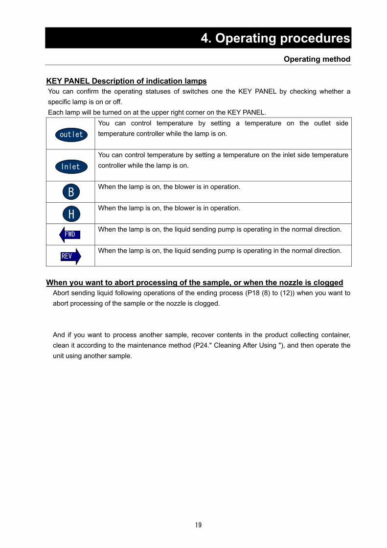
KEY PANEL Description of indication lamps You can confirm the operating statuses of switches one the KEY PANEL by checking whether a specific lamp is on or off. Each lamp will be turned on at the upper right corner on the KEY PANEL.
You can control temperature by setting a temperature on the outlet side temperature controller while the lamp is on.
You can control temperature by setting a temperature on the inlet side temperature controller while the lamp is on.
When the lamp is on, the blower is in operation.
When the lamp is on, the blower is in operation.
When the lamp is on, the liquid sending pump is operating in the normal direction.
When the lamp is on, the liquid sending pump is operating in the normal direction.
When you want to abort processing of the sample, or when the nozzle is clogged
Abort sending liquid following operations of the ending process (P18 (8) to (12)) when you want to abort processing of the sample or the nozzle is clogged.
And if you want to process another sample, recover contents in the product collecting container, clean it according to the maintenance method (P24." Cleaning After Using "), and then operate the unit using another sample.
Inlet
B
H
outlet
REV
FWD
20
4. Operating procedures Related Figure between Blower and Temperature/Drying Air Quantity
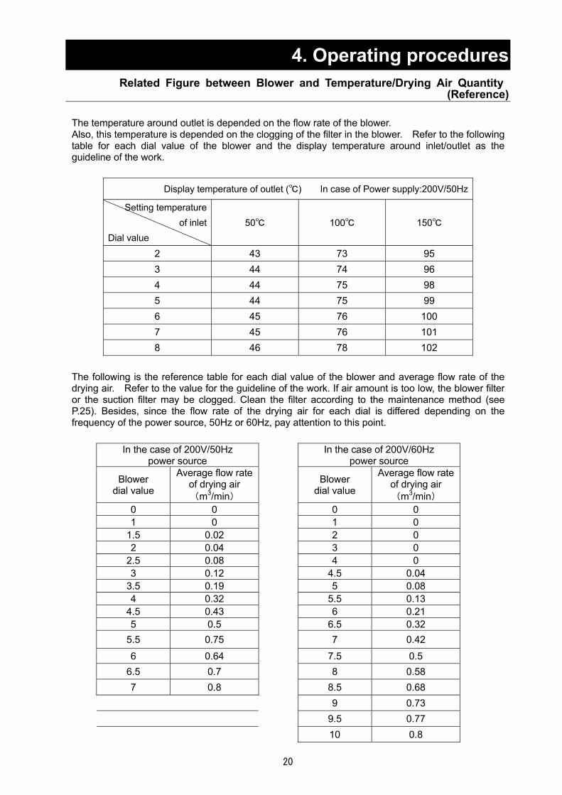
(Reference) The temperature around outlet is depended on the flow rate of the blower. Also, this temperature is depended on the clogging of the filter in the blower. Refer to the following table for each dial value of the blower and the display temperature around inlet/outlet as the guideline of the work.
Display temperature of outlet () In case of Power supply:200V/50Hz
Setting temperature of inlet
Dial value 50 100 150
2 43 73 95 3 44 74 96 4 44 75 98 5 44 75 99 6 45 76 100 7 45 76 101 8 46 78 102
The following is the reference table for each dial value of the blower and average flow rate of the drying air. Refer to the value for the guideline of the work. If air amount is too low, the blower filter or the suction filter may be clogged. Clean the filter according to the maintenance method (see P.25). Besides, since the flow rate of the drying air for each dial is differed depending on the frequency of the power source, 50Hz or 60Hz, pay attention to this point.
In the case of 200V/50Hz
power source In the case of 200V/60Hz
power source
Blower dial value
Average flow rateof drying air (m3/min)
Blower dial value
Average flow rate of drying air (m3/min)
0 0 0 0 1 0 1 0
1.5 0.02 2 0 2 0.04 3 0
2.5 0.08 4 0 3 0.12 4.5 0.04
3.5 0.19 5 0.08 4 0.32 5.5 0.13
4.5 0.43 6 0.21 5 0.5 6.5 0.32
5.5 0.75 7 0.42
6 0.64 7.5 0.5 6.5 0.7 8 0.58 7 0.8 8.5 0.68 9 0.73 9.5 0.77
10 0.8

21
5. Handling Precautions
Warning 1. Substances that cannot be used
Never use an explosive, a flammable, or a substance that contains them. Otherwise, an explosion or a fire may result.ADL311S supports organic solvents by connecting it to the optional GAS410. Carefully read the operation manual of GAS410 and take special care for handling of organic solvents. See P.42 "15. List of Dangerous Substances ".
2. If a problem occurs
f smoke or strange odor should come out of this unit for some reason, turn off the power key right away, and then turn off the circuit breaker and the main power. Immediately contact a service technician for inspection. If this procedure is not followed, fire or electrical shock may result. Never perform repair work yourself, since it is dangerous and not recommended.
3. Do not touch the part with high temperature
The chamber, cyclone, and peripheral part become high temperature during and just after operation. Do not touch these parts, for there may be caused heat injury.
Caution 1. Do not put anything on this unit。
Do not put anything on this unit. It will cause injury if fall.
2. During a thunder storm
During a thunderstorm, turn off the power key immediately, then turn off the circuit breaker and the main power. If this procedure is not followed, fire or electrical shock may be caused.
5. Recovering after power failure
When power is supplied after a power failure, the device automatically starts operation again with the same state as just before the power failure.
6. After installing
It may cause injure to a person if this unit falls down or moves by the earthquake and the impact, etc.. To prevent, take measures that the unit cannot fall down.

22
5. Handling Precautions Drying Method under Appropriate Condition
(1) The best appropriate drying condition is differed depending on the sample to be dried. Inquire
the data for the partial example of various samples. (2) Adjust the drying condition so as to match to the various errors to be possible to occur such as
too much adhesion of the sample to the drying chamber, too high density of the sample, too low temperature around inlet, too high or too low pressure of spray air, too much feeding amount of sample.
(3) When the spray direction is changed by the adhesion of the sample to the spray nozzle during operation, turn "ON" the pulse jet switch, and blowout the adhesive from the tip of the nozzle using pressurizing air. Even thought the adhesive is not blowout, dismount the spray nozzle, and clean the tip of the nozzle using the soaked paper in water.
(4) The possible cause for adhesion of the sample to the cyclone part is either not evaporating the solvent (distilled water or ion-exchanged water) with enough or the property of the sample itself (low melting point, absorption, etc.)。
For depleting the powder, increasing the amount of heat for sample is the best measure. Therefore, perform either measure below, to increase either temperature around inlet or flow rate of the drying air, or to reduce the feeding amount of the sample, that is, to reduce the difference between the temperature around inlet and that around outlet. When the reason is in the property of the sample itself, adjust the sample by adding the special additive, etc. (5) In the case that the hygroscopicity is high, the product may become the moist powder in the container. Change the drying condition following the method in (4), or, if required, heat up the container for product before operation.
(6) The orifice of the spray nozzle is 460μ. If the sample is blocked with suspension at orifice part impetuously, use the 508μ and 711μ nozzles prepared for the orifice as optional (Nozzle main body P24." Cleaning After Using ",the nozzle main body, the needle, and the ring in the exploded view of the spray nozzle are common with the 406μ nozzle)These 508μ and 711μ nozzles are differed on the point of the size of the spray pattern and particle diameter of the drop slightly compared to the 406μ one, and these differences may affect the interference status. Refer to the Graph 1 for the relation between spray air pressure and spray airflow rate (atmospheric conversion). グラフ.1
(7) The too small powder (few μ or less) among dried ones is impossible to be collected, and exhausted to the outside through the blower. If this exhausted amount of the too small powder becomes more, decrease either spray airflow rate or spray air pressure. Also, since the particle diameter becomes smaller as the density of the sample is lower, adjust the density of the sample if required.
Spra
y ai
rflow
rate
(atm
osph
eric
con
vers
ion)
.
Spray air pressure Graph 1
23
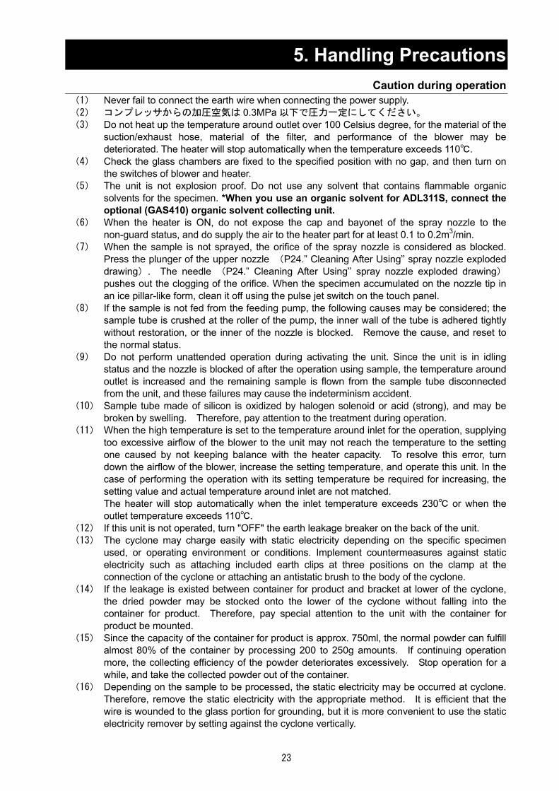
5. Handling Precautions Caution during operation
(1) Never fail to connect the earth wire when connecting the power supply. (2) コンプレッサからの加圧空気は 0.3MPa 以下で圧力一定にしてください。 (3) Do not heat up the temperature around outlet over 100 Celsius degree, for the material of the
suction/exhaust hose, material of the filter, and performance of the blower may be deteriorated. The heater will stop automatically when the temperature exceeds 110.
(4) Check the glass chambers are fixed to the specified position with no gap, and then turn on the switches of blower and heater.
(5) The unit is not explosion proof. Do not use any solvent that contains flammable organic solvents for the specimen. *When you use an organic solvent for ADL311S, connect the optional (GAS410) organic solvent collecting unit.
(6) When the heater is ON, do not expose the cap and bayonet of the spray nozzle to the non-guard status, and do supply the air to the heater part for at least 0.1 to 0.2m3/min.
(7) When the sample is not sprayed, the orifice of the spray nozzle is considered as blocked. Press the plunger of the upper nozzle (P24.” Cleaning After Using” spray nozzle exploded drawing). The needle (P24.” Cleaning After Using” spray nozzle exploded drawing)pushes out the clogging of the orifice. When the specimen accumulated on the nozzle tip in an ice pillar-like form, clean it off using the pulse jet switch on the touch panel.
(8) If the sample is not fed from the feeding pump, the following causes may be considered; the sample tube is crushed at the roller of the pump, the inner wall of the tube is adhered tightly without restoration, or the inner of the nozzle is blocked. Remove the cause, and reset to the normal status.
(9) Do not perform unattended operation during activating the unit. Since the unit is in idling status and the nozzle is blocked of after the operation using sample, the temperature around outlet is increased and the remaining sample is flown from the sample tube disconnected from the unit, and these failures may cause the indeterminism accident.
(10) Sample tube made of silicon is oxidized by halogen solenoid or acid (strong), and may be broken by swelling. Therefore, pay attention to the treatment during operation.
(11) When the high temperature is set to the temperature around inlet for the operation, supplying too excessive airflow of the blower to the unit may not reach the temperature to the setting one caused by not keeping balance with the heater capacity. To resolve this error, turn down the airflow of the blower, increase the setting temperature, and operate this unit. In the case of performing the operation with its setting temperature be required for increasing, the setting value and actual temperature around inlet are not matched. The heater will stop automatically when the inlet temperature exceeds 230 or when the outlet temperature exceeds 110.
(12) If this unit is not operated, turn "OFF" the earth leakage breaker on the back of the unit. (13) The cyclone may charge easily with static electricity depending on the specific specimen
used, or operating environment or conditions. Implement countermeasures against static electricity such as attaching included earth clips at three positions on the clamp at the connection of the cyclone or attaching an antistatic brush to the body of the cyclone.
(14) If the leakage is existed between container for product and bracket at lower of the cyclone, the dried powder may be stocked onto the lower of the cyclone without falling into the container for product. Therefore, pay special attention to the unit with the container for product be mounted.
(15) Since the capacity of the container for product is approx. 750ml, the normal powder can fulfill almost 80% of the container by processing 200 to 250g amounts. If continuing operation more, the collecting efficiency of the powder deteriorates excessively. Stop operation for a while, and take the collected powder out of the container.
(16) Depending on the sample to be processed, the static electricity may be occurred at cyclone. Therefore, remove the static electricity with the appropriate method. It is efficient that the wire is wounded to the glass portion for grounding, but it is more convenient to use the static electricity remover by setting against the cyclone vertically.

24
6. Maintenance Method Daily Inspection and Maintenance
Warning Disconnect the power cable from the power source when doing an inspection or maintenance
unless needed. Perform the daily inspection and maintenance after returning the temperature of this unit to the
normal one. Do not disassemble this unit.
Caution Use a well-drained soft cloth to wipe dirt on this unit. Do
not use benzene, thinner or cleanser for wiping. Do not scrub this unit. Deformation, deterioration or color change may result in.
ベンジンシンナー
クレンザー
Cleaning After Using (1) After completing the operation, remove the attachments following the process “Preparations " on
P.11 in reverse order. (2) Clean the portion of attachment to which the powder is adhered. (3) Flow the distilled water into the sample tube by pressing the pump switch, and remove the
contaminant attached to the inner of the part. (4) Remove the spray air tube and sample tube from the spray nozzle, and disassemble the nozzle
as shown in the Photo 1. After disassembling, clean it using the supersonic cleaner. Remaining the contaminant to the inner of the part may cause the insufficient spray. Therefore, clean it completely.
Spray nozzle exploded drawing
Nozzle fixing (only for GF 200)
Plunger Needle
Gasket
Main unit of nozzle Nozzle for liquid
Ring
Nozzle for air

25
6. Maintenance Method Daily Inspection and Maintenance
Filter Cleaning Clean up the filter in blower periodically.
1) Open the door at the bottom of the front surface of the unit, and disconnect the hose from the blower.
2) Open the front cover by removing the two fastening plates for the cover from the upper surface of the blower, and open the front cover, and take the filter out.
3) The followings are the cleaning procedures of the filter. ① Wash the filter pressing in the water repeatedly, and air-dry it. ② Compressed air blowing. ③ Vacuum cleaning with a cleaner. ④ Press washing the filter after being immersed into the solvent that hot water (approx. 40
Celsius degree) and neutral detergent are mixed at a rate of 5:95 one whole day and night, then rinse it with water and air-dry it.
4) When assembling, reversely execute the above procedure. Turn the soft surface of the filter to windward when installing the filter.
Suction filter
Regularly clean the suction filter. 1. The suction filter is stored in the suction filter case at the rear of the main unit.
2. Clean the suction filter with the same procedures in section 3. above.
Monthly maintenance Check the earth leakage breaker function.
・ Connect the power cord. ・ Turn the breaker on. ・ Push the red test switch by a ballpoint pen etc. If there
is no problem, the earth leakage breaker will be turned off.
Test button
26
7. Long storage and disposal When not using this unit for long term / When disposing
Caution Warning When not using this unit for long term… Turn off the earth leakage breaker and original
power source for safe without fail. Also, store the glass unit after removing it from the main unit. When the glass unit is contacted to the external, it may cause the breakage.
When disposing… Keep out of reach of children. Remove the power cord.
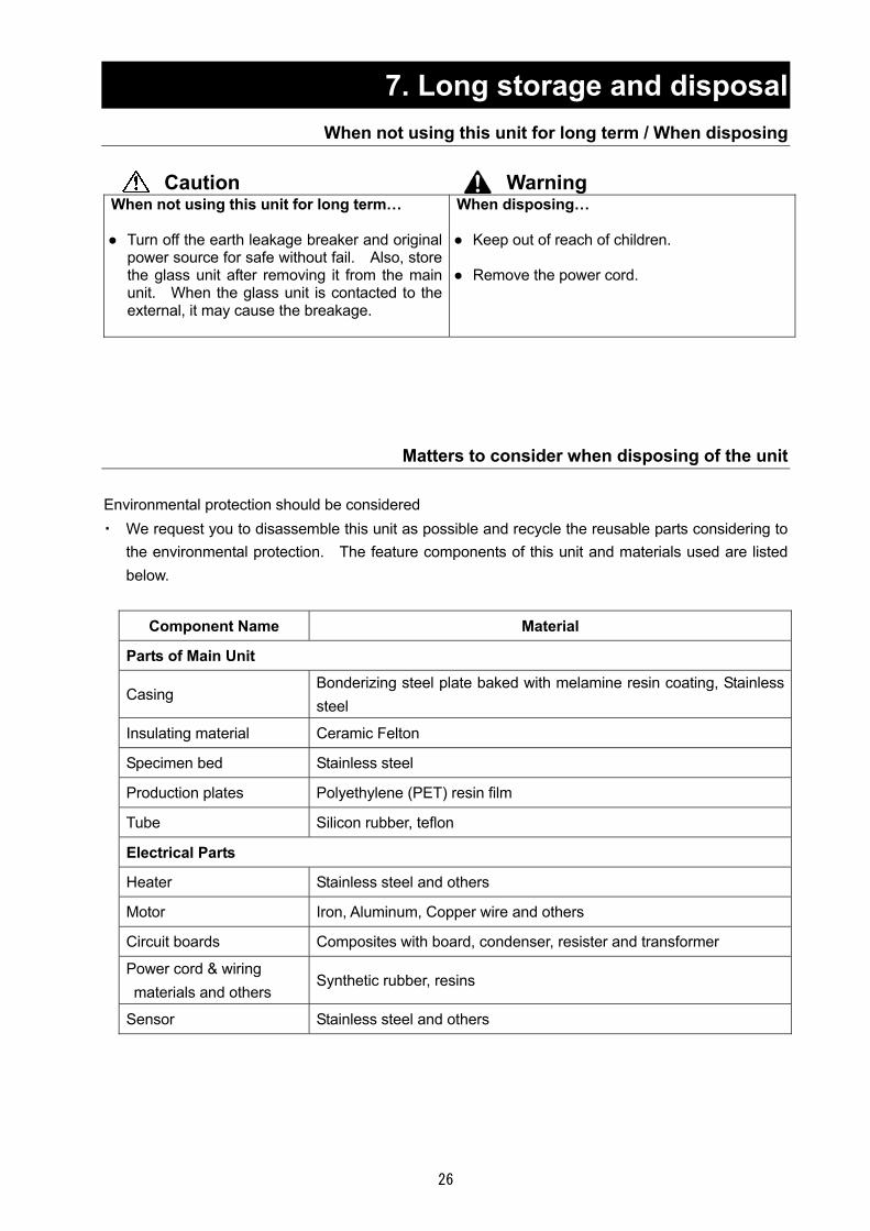
Matters to consider when disposing of the unit Environmental protection should be considered ・ We request you to disassemble this unit as possible and recycle the reusable parts considering to
the environmental protection. The feature components of this unit and materials used are listed below.
Component Name Material
Parts of Main Unit
Casing Bonderizing steel plate baked with melamine resin coating, Stainless steel
Insulating material Ceramic Felton
Specimen bed Stainless steel
Production plates Polyethylene (PET) resin film
Tube Silicon rubber, teflon
Electrical Parts
Heater Stainless steel and others
Motor Iron, Aluminum, Copper wire and others
Circuit boards Composites with board, condenser, resister and transformer
Power cord & wiring materials and others
Synthetic rubber, resins
Sensor Stainless steel and others
27
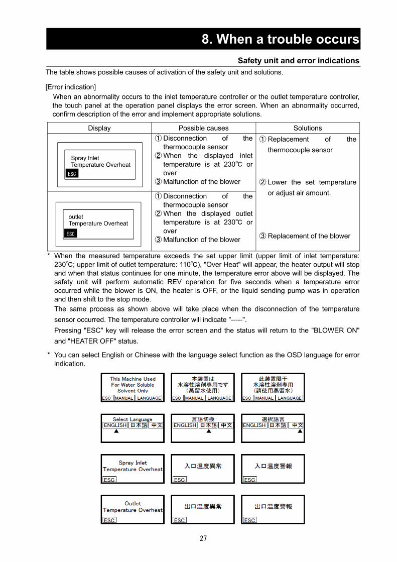
8. When a trouble occurs Safety unit and error indications
The table shows possible causes of activation of the safety unit and solutions. [Error indication]
When an abnormality occurs to the inlet temperature controller or the outlet temperature controller, the touch panel at the operation panel displays the error screen. When an abnormality occurred, confirm description of the error and implement appropriate solutions.
Display Possible causes Solutions
① Disconnection of the thermocouple sensor
② When the displayed inlet temperature is at 230 or over
③ Malfunction of the blower
① Disconnection of the thermocouple sensor
② When the displayed outlet temperature is at 230 or over
③ Malfunction of the blower
① Replacement of the thermocouple sensor
② Lower the set temperature
or adjust air amount.
③ Replacement of the blower
* When the measured temperature exceeds the set upper limit (upper limit of inlet temperature: 230; upper limit of outlet temperature: 110), "Over Heat" will appear, the heater output will stop and when that status continues for one minute, the temperature error above will be displayed. The safety unit will perform automatic REV operation for five seconds when a temperature error occurred while the blower is ON, the heater is OFF, or the liquid sending pump was in operation and then shift to the stop mode. The same process as shown above will take place when the disconnection of the temperature sensor occurred. The temperature controller will indicate "-----". Pressing "ESC" key will release the error screen and the status will return to the "BLOWER ON" and "HEATER OFF" status.
* You can select English or Chinese with the language select function as the OSD language for error
indication.
Spray Inlet Temperature Overheat
ESC
ESC
outlet Temperature Overheat

28
8. When a trouble occurs Confirmation and language select for the manual
You can select English or Chinese with the language select function as the OSD language for the manual. [Confirmation and language select for the manual] Pressing ESC key will return to the standby screen.

29
8. In the Event of Failure… Trouble Shooting
Symptoms Possible causes Countermeasures
The POWER does not turn ON.
ELB is turned OFF Malfunction of the power supply The wire ire short-circuited. Malfunction of power switch
Turn the ELB ON Check the power supply circuit Replace the cord Replace the power switch
Blower does not activate.
Incorrect connecting of the connector of blower
Breaking of blower input cord Blower switch failure
Blower motor failure
Blower motor brush failure Blower circuit failure and wiring
failure
Connect correctly.
Replace the cart. Replace the touch panel,
sequencer or thermo regulator. Replace the motor or motor
substrate Replace the brush Maintain or replace the part
Heater does not activate.
Incorrect connecting of the connector of heater
Activated the protection circuit caused by the failure of the other device (displayed error)
Activated the protection circuit without turning on the blower switch
Heater disconnection Heater switch failure
Heater circuit failure and wiring
failure
Connect correctly.
Solve the problem, and turn ON the switch.
Turn ON the blower, and then turn
ON the heater switch. Replace the part. Replace the touch panel or
sequencer Maintain the part or replace the
thermo regulator. Feeding pump does not activate
The indicator of the pump adjusting dial is at "0"
Pump switch failure
Pump motor failure Pump circuit failure and wiring
failure Imperfect nozzle attachment
Adjust the dial.
Replace the touch panel or sequencer
Replace the motor or driver Maintain the part
Check and adjsutment of
attachment status of the nozzle Pulse jet does not activate
Failure of pressuring air source
Connecting failure of tube Solenoid valve failure Pulse jet switch failure
Pulse jet circuit failure and wiring
failure
Make arrangement aiming for appropriate status.
Maintain or replace the part. Replace the part. Replace the touch panel or
sequencer Maintain the part

30
8. In the Event of Failure… Trouble Shooting
Problem Possible Cause Solution
Thermo regulator failure
Defective display function Sensor failure Activated overheating protection
function
Maintain or replace the part. Replace the part. Lower the temperature setting
Adjusting dial (Not activated blower and pump)
Adjusting circuit failure and wiring failure
Lack of capacity of heater due to
excessive drying airflow
Maintain the part or replace the thermo regulator.
No error. For operating this unit with high temperature, decrease the flow rate of the drying air or increase the setting value.
In the case if the error other than listed above occurred, turn off the power switch and
primary power source immediately. Contact the shop of your purchase or nearest Yamato Scientific Service Office.

31
9. After Service and Warranty When requesting a repair
When requesting a repair
If any trouble occurs, immediately stop operation, turn the power switch off, pull out the power plug and contact your dealer, our sales office or our customer service center.
Information necessary for requesting a repair Model name of the product Serial number Date (y/m/d) of purchase Description of trouble (as in detail as possible)
Be sure to indicate the warranty card to our service representative.
Warranty card (attached separately) Warranty card is given by your dealer or one of our sales offices and please fill in your dealer,
date of purchase and other information and send it to our customer service center by Facsimile (03-3231-6523). Then, store it securely.
Warranty period is one full year from the date of purchase. Repair service for free is available
according to the conditions written on the warranty card.
For repairs after the warranty period consult your dealer, one of our sales offices or our customer service center.
Paid repair service is available on your request when the product’s functionality can be maintained by repair.
Minimum holding period of repair parts
The minimum holding period of repair parts for this product is seven years after end of production. Repair parts here refer to parts necessary for maintaining performance of the product.
See the warranty card or the nameplate on the unit. See the section “3.Names of parts and their function” on page 9.

32
10. Specification Specifications of main unit
Configuration Splay Dryer+Mini Splay Attachment [GF-300] Function Splay drying
Sample for drying Solution, Suspension, Emulsion (Flammable organic solvent is invalid.)Total weight Approx. 91kg
Thermo regulator PID digital thermo regulator
Heater 2kW(AC200V)~2.88kW(AC240V)
Blower Bypass type commutator blower
Stirring mechanism Induction motor
Sample feeding pump
Proportioning Peli pump
Pressure gauge for spray air
Pressure gauge for bourdon tube Measurement range: 0 to 294kPa
Blowout mechanism for pressurizing air
Use pulse jet type solenoid valve
Temperature adjustment range
INLET:0~220 (differed depending on airflow), OUTLET:0~60
Temperature adjustment accuracy
±1
Temperature display Digital display of the temperature around Inlet/Outlet
(metal-sheathed thermocouple element K) Adjusting range for drying air
0~0.7m3/min
Power supply *1 AC200V single phase 16A(AC220V 17A AC240V 18A)
External dimensions *2)(W×D×H)
580×420×1125
Weight Approx. 80kg
・ Specimen tube Silicon I.D.2 ×O.D.4 ×1m 2
ADL3
11/A
DL3
11S
Attached accessories
・ Outlet temperature sensor ・ Exhaust hose Made of vinyl chloride I.D.:50 ×2m ・ Hose band #64 ・ Sample box ・ Knurled screw ・ Tetlon braded hose 5m (for connecting pressurized air) ・ Hose clamp ・ Fuse ・ O-ring ・ Earth wire ・ Warranty card ・ Operation manual
1 1 1 1 2 1 2 1 1 1 1 1
ADL311S, compared to ADL311, supports connection to the organic solvent recovery unit GAS410.

33
10. Specification
Model GF300 Amount of water evaporation
Max. Approx. 1300ml/h
Spray nozzle Binary Nozzle 1A Drying chamber Made from super hard glass Cyclone Made from super hard glass Container for product Made from super hard glass Dust removal of nozzle tip
Pulse jet type (used the pressuring air blower mechanism for GB210 model)
Weight Approx. 11
Min
i Spl
ay A
ttach
men
t〔G
F300
〕
Parts list
Cyclone Drying chamber Product collecting container Container holding band Packing 40A, 50A Power clamp 40A, 50A Cap Connecting ferrule (D) PFA wave shaped tube 1-1/2, 3 feet long (for connecting the cyclone) Hose clip Distributor (O-rings P16, P135 included) Hex bolt M6 x 20 Flat washer M6 Spring washer M6 Aluminum honeycomb Pipe Spray nozzle Round single-ended wrench Polyethylene tank for 100g of 5% sodium chloride solution Warranty card
1set 1set
1 1
1each1each
1 1 1 2 1 3 3 3 1 1 1 1 1 1
*1 Including capacity of service receptacle (2A). *2 The outer dimension does not include the projection part. Please remind that this product may be changed the specification and others for revision without any announce to the user.

34
11. Wiring Diagram ADL311 Wiring Diagram
In
case
of
di
ffere
ntvo
ltage
, cha
nge
over
the
term
inal
. T1
-5: 2
00V
T1
-4: 2
20V
T1
-3: 2
40V
Alar
m
outp
ut
Alar
m
outp
ut
Inle
t tem
p. c
urre
nt o
utpu
t
Out
let t
emp.
cur
rent
out
put
Atta
ched
cab
le
(300
mm
)
SSR
outp
utSS
Rou
tput
Atta
ched
cab
le
(300
mm
)
Atta
ched
cab
le
(300
mm
)
Atta
ched
cab
le
Atta
ched
cab
le
Br
R
O
Y
Gr
Bl
W
Out
put
bloc
k
Br: B
row
n R
: Red
O
: Ora
nge
Y: Y
ello
w
Gr:
Gre
en
Bl: B
lack
W
: Whi
te

35
11. Wiring Diagram ADL311 Wiring Diagram
Symbol Part name Symbol Part name ELB Electric Leakage Breaker VR1 Blower volume Tr Stepdown transformer VR2 Liquid sending pump volume
T1~T3 Terminal block MV1 PULSE JET solenoid valve T-Panel Touch panel M1 Blower motor
PLC Sequencer M2 Liquid sending pump motor TH1・TH2 Temperature sensor SC Service outlet
TIC1 Inlet temperature controller
F Current fuse (2A)
TIC2 Outlet temperature indicator
X1 Power relay
FCS PC Blower speed control substrate
X2 FAN relay
PUMP PC Liquid sending pump speed control substrate
SW1 Power switch
SSR Solid-state relay SW2 Inlet/outlet temperature control selector switch
H1・H2 Heater CN1~CN4 Relay connector

36
11. Wiring Diagram ADL311S Wiring Diagram
Atta
ched
cab
le
(300
mm
)
Inle
t tem
p. c
urre
nt o
utpu
t
Out
let t
emp.
cur
rent
out
put
Trap
tem
p.cu
rrent
out
put
SSR
out
put
In
case
of
di
ffere
ntvo
ltage
, ch
ange
ove
r th
ete
rmin
al.
T1-5
: 200
V
T1-4
: 220
V
T1-3
: 240
V
Out
put b
lock
Br
R
O
Y
Gr
Bl
W
Br: B
row
n R
: Red
O
: Ora
nge
Y: Y
ello
w
Gr:
Gre
en
Bl: B
lack
W
: Whi
te
Alar
m o
utpu
t
Blac
k W
hite
Red
G
reen
Yello
w
Brow
n Bl
ue
Gre
y
Ora
nge
Aqua
Pink
Pale
yel
low
Blac
k W
hite
R
ed
Gre
en
Yello
w
Brow
n Bl
ue
Gre
y O
rang
e Aq
ua
Pink
Pa
le y
ello
w
(Fem
ale
pin)
(Mal
e pi
n)
Alar
m
outp
ut
SSR
out
put
Atta
ched
cab
le
Atta
ched
cab
le
(300
mm
)
Atta
ched
cab
le
(300
mm
)
Atta
ched
cab
le

37
11. Wiring Diagram ADL311S Wiring Diagram
Symbol Part name Symbol Part name ELB Electric Leakage Breaker MV1 PULSE JET solenoid valve Tr Stepdown transformer MV2 Solenoid valve for switching
GAS pipes T1 to T3 Terminal block M1 Blower motor T-Panel Touch panel M2 Liquid sending pump motor
PLC Sequencer SC Service outlet TH1 & TH2 Temperature sensor F Current fuse (2A)
TIC1 Inlet temperature controller
X1 Power relay
TIC2 Outlet temperature indicator
X2 FAN relay
FCS PC Blower speed control substrate
SW1 Power switch
PUMP PC Liquid sending pump speed control substrate
SW2 Inlet/outlet temperature control selector switch
SSR Solid-state relay SW3 Nozzle detection reset switchH1 & H2 Heater CN1 to CN6 Relay connector
VR1 Blower volume CN11 & CN12 Panel connector VR2 Liquid sending pump
volume

38
12. System Chart System Chart
Number Part name Number Part name
① Heater ⑨ Blower ② Inlet temperature sensor ⑩ Solenoid valve
③ Distributor ⑪ 3-way solenoid valve (ADL311S only)
④ Drying chamber ⑫ Needle valve ⑤ Cap ⑬ Pressure meter ⑥ Outlet temperature sensor ⑭ Spray nozzle ⑦ Cyclone ⑮ Liquid sending pump
⑧ Product collecting container ⑯ Nozzle cooling connecting port
For connecting optional unit (GAS410)
Only ADL311S
Connecting pressurized air
Suction

39
13. Principle of Operation Principle of Operation Refer to " System Chart" on P.38.
The sample is fed from the appropriate container to ⑭ spray nozzle with ⑮ feeding pump. Moreover, the compressed air pressure from the compressor is regulated by ⑫ needle valve, and sent to ⑭ spray nozzle. At the tip of the nozzle, the compressed air mixed with the sample, and the mixed sample is sprayed inside ④ drying chamber. This sample becomes drop shape that the particle diameter is approx. 20μ and the surface area is 3,000 cm2 per 1 litter of sample. On the other side, air is suctioned into the unit by ⑨ blower, and heated up till the temperature set on heater. Since the contact area of the heated air and the sample is very large, the approx. 90% or more of the moisture will be evaporated in the dry chamber momentarily.
The sample that became fine powder by drying is fed to ⑦ cyclone under further drying, and separated from the evaporated part here, and then, fed to ⑧ container for product. Time after the sample is sprayed with the nozzle till it is fed into this container does not take 0.5 seconds. Moreover, since the sample powder is always surrounded with the solvent vapor (moisture vapor), the temperature does not rise extremely around the particle due to the vaporization heat. Therefore, in case of the heat-sensitive material such as an enzyme, disintegration can be executed without dropping degree of activity even under the condition as a temperature around outlet= 80 Celsius degree. The evaporated moisture is evacuated to outside via the blower.
The temperature conditions under examination are displayed on the display panel by the inlet temperature sensor and the outlet temperature sensor. Moreover, the airflow that dries the sample is measured by the wind velocity sensor in the wind-flow tube, and is displayed on the display panel.
In case that the sample adhesion to the nozzle tip is outstanding, open ⑩ solenoid valve to let the pressurizing air blow to the nozzle tip from ③ distributor in order to remove the adhesives. If necessary, remove ⑤ cap to take the outside air into the inside of the chamber.

40
14. Replacement parts table Common parts for ADL311/ADL311S
Part name Standards Manufacturer Code No.
※ Packing (C) AD311S-40440 Neoprene rubber
Yamato Scientific LT00027737
※ Packing (D) AD311S-40430 Neoprene rubber
Yamato Scientific LT00027734
※ Packing (E) AD311S-40550 Neoprene rubber
Yamato Scientific LT00027740
※ Filter AD311S_4054 0 PET
Yamato Scientific LT00027739
※ Heat resistant hose GS type 38×42×L650 TIGERS POLYMER LT00027762
※ Filter AD311S_40400 PET For suction port LT00027657
※ Sheathed heater AD311S_30020 Yamato Scientific LT00027773
Bellows MFK040-L130 Connected to the upper cylindrical pipe
MIRAPRO LT00027775
Blower motor SBW-800A Matsushita 2150146002
※ Teflon tube φ8×φ6×L1000 Yamato Scientific 3040146003
Clamp MCK-1040 MIRAPRO P57
※ Center ring MCK-2040 MIRAPRO LT00027798
※ O-ring P23 4-types D Viton For upper cylindrical pipe Yamato Scientific 4210026024
※ O-ring P145 4-types D Viton For upper cylindrical pipe Yamato Scientific 4210026045
Pressure meter DU-1/4-60-3K Nisshin Gauge 5050036002
Needle valve 2412T-S-1/8-7 Kojima 3150116002
Toggle switch 2M-2032 Nikkai LT00027715
Switch HLS112A-G Fujisoku 2010086022
Volume RV24YN20S B103 077C TOCOS LT00027710
Volume RV24YN20S B204 069C TOCOS LT00027711
Motor FY8PF15N-D3 For sending liquid JAPAN SERVO LT00027675
Driver FYD815SD3 For sending liquid JAPAN SERVO LT00027693
Gear head 8H30FBN-100 For sending liquid JAPAN SERVO LT00027684
Bearing SSR-1030ZZ For sending liquid NMB 4180126001
Solenoid valve VX2230K-02-1G1 SMC LT00027695
※ Teflon flexible tube φ6.35×φ4.35×200 Yamato Scientific 3040000015
Temperature sensor(Outlet) Yamato Scientific LT00026545
Temperature sensor harness (Outlet) Yamato Scientific LT00026546
Temperature sensor(Inlet) Yamato Scientific LT00026543
PLC connecting cable GT10-C10-R4-8P Mitsubishi LT00027716

41
14. Replacement parts table
Part name Standards Manufacturer Code No.
Touch panel GT1020-LBLW 3.7 inches Mitsubishi LT00025833
PLC IN16/OUT10 FX1S-30MR Mitsubishi LT00027663
Output block FX1N-2EYT-BD Mitsubishi LT00027717
Temperature controller TTM204-Q-PI-RSV Toho Denshi LT00027709
Electric Leakage Breaker BJS203100S1 Matsushita 2060050011
SSR TRS1225 Toho Denshi LT00029541
Relay LY1N AC100V Omron LT00027662
Socket PTF08A Omron LT00017832
Stepdown transformer AD21-015KB2 TOYOZUMI LT00000982
Switching power LEA50F-24 COSEL LT00027661
Fan control substrate YY0609-A/FSPC Ryowa LT00020329
Liquid tube GAS41-40610 Silicone Yamato Scientific LT00027796
Fuse FGMB-125V2A-200P MISUMI LT00027794 Parts for ADL311S Part name Standards Manufacturer Code No.
Micro switch SS-01GL2 Nozzle port
Omron A0020084
Solenoid valve VX3334K-02-1GR1-B 3-way valve
SMC LT00031493
Interface connector RNJC-RM-20-12-A-1 MISUMI LT00027660
Interface connector RNJC-RF-20-12-A-1 MISUMI LT00027659
Note: Parts marked with * are consumable parts.

42
14. Replacement parts table Replacement parts for GF300
Part name Standards Manufacturer Code No.
Drying chamber system GF300-30000 Ultra hard glass
Yamato Scientific LT00028136
Cyclone set GF300-30060 Ultra hard glass
Yamato Scientific LT00028785
Container holding band GF300-40000 Stainless steel Yamato Scientific LT00027540
Nozzle set GF300-30100 Yamato Scientific LT00028786
※ O-ring P16 4 types D Viton Yamato Scientific 4210026021
※ Aluminum honeycomb GF300-40120 Yamato Scientific LT00027548
※ O-ring P135 4 types D Viton Yamato Scientific F0020073
※ Cap GF300-40100 Silicone Yamato Scientific LT00027544
Connecting ferrule (D) GF300-40080 LT00027543
※ PFA wave formed tube 1-1/2, 3 feet (915mm) long IIDA GOMU LT00027545
Hose clip JCS-Win-2A φ35~50 Okada Industry LT00027550
※ Packing 40A Silicone OSAME
INDUSTRIES F0220141
※ Packing 50A Silicone OSAME
INDUSTRIES F0220143
Power clamp 40A OSAME
INDUSTRIES R0100009
Power clamp 50A OSAME
INDUSTRIES R0100012
Product collecting container GF300-30090 Yamato Scientific LT00027539
Clean out needle Additional machining drawing
GF300-40190 14293-6-1/16-SS Secondary machining
SSJ LT00027552
※ Packing CP-4042-2-TEF SSJ 3280016002
※ Gasket (A) CP104369-TEF SSJ 3280016003
※ Gasket (B) CP3612-TEF SSJ 3280016006
※ O-ring JASO-1017 Haika 4210076002
Note: Parts marked with * are consumable parts.

43
15. List of Dangerous Substances
Never use explosive substances, flammable substances and substances that include explosive or flammable ingredients in this unit. Otherwise explosion or fire may result
ADL311S supports organic solvents by connecting it to the optional GAS410. Carefully read the operation manual of GAS410 and take special care for handling of organic solvents.
Nitroglycol, glycerine trinitrate, cellulose nitrate and other explosive nitrate esters
Trinitrobenzen, trinitrotoluene, picric acid and other explosive nitro compounds
Expl
osiv
e su
bsta
nce
Expl
osiv
e su
bsta
nce
Acetyl hydroperoxide, methyl ethyl ketone peroxide, benzoyl peroxide and other organic peroxides
Expl
osiv
e su
bsta
nces
Metal “lithium”, metal “potassium”, metal “natrium”, yellow phosphorus, phosphorus sulfide, red phosphorus, celluloids, calcium carbide (a.k.a, carbide), lime phosphide, magnesium powder, aluminum powder, metal powder other than magnesium and aluminum powder, sodium dithionous acid (a.k.a., hydrosulphite)
Potassium chlorate, sodium chlorate, ammonium chlorate, and other chlorates
Potassium perchlorate, sodium perchlorate, ammonium perchlorate, and other perchlorates
Potassium peroxide, sodium peroxide, barium peroxide, and other inorganic peroxides
Potassium nitrate, sodium nitrate, ammonium nitrate, and other nitrates
Sodium chlorite and other chlorites Oxi
dizi
ng s
ubst
ance
s
Calcium hypochlorite and other hypochlorites
Ethyl ether, gasoline, acetaldehyde, propylene chloride, carbon disulfide, and other substances with ignition point at a degree 30 or more degrees below zero.
n-hexane, ethylene oxide, acetone, benzene, methyl ethyl ketone and other substances with ignition point between 30 degrees below zero and less than zero.
Methanol, ethanol, xylene, pentyl acetate, (a.k.a.amyl acetate) and other substances with ignition point between zero and less than 30 degrees.
Flam
mab
le s
ubst
ance
s
Kerosene, light oil, terebinth oil, isopenthyl alcohol(a.k.a. isoamyl alcohol), acetic acid and other substances with ignition point between 30 degrees and less than 65 degrees.
Flam
mab
le s
ubst
ance
s
Com
bust
ible
ga
s Hydrogen, acetylene, ethylene, methane, ethane, propane, butane and other gases combustible at 15 at one air pressure.
(Quoted from the separate table 1 in Article 6, the enforcement order of
the Industrial Safety and Health Law)

44
16. Standard installation manual *Follow the items below to make installation. (Check the procedures separately for optional parts or products of special specifications.)
Model Serial number Date Installation manager
(company name) Installation manager
Judgment
Item Implementation method Table of contents No. Section for
reference in manual Judgment
Specification
1 Accessories Check of quantity according to the accessory columns
10.Specifications
2 Installation ・ Visual check of the environmental
status Caution: Surrounding environment
2. Before using this unit ・ At the installation site...
Operation related matters
1 Source voltage
・ Measure customer side voltage (ELB etc.) with a tester
・ Measure voltage while the heater is operating
(Shall meet the standards) Caution: Use a power supply that
meets the standard when you are going to install it on a plug or an ELB.
2. Before using this unit ・ Be sure to connect the earth
wire... ・ Use the dedicated outlet for
power supply 4. Operating procedures Preparations (1) & (2) 10. Specifications ・ Power supply
2 Installation of the attachment
Preparations ・ Connecting the exhaust duct ・ Connection to the compressor ・ Connection of the spray nozzle
cooling mechanism (as necessary) ・ Checking the contents of the GF300
set ・ Installation of the distributor ・ Installation of the nozzle guide ・ Installation of the drying chamber ・ Installation of the temperature sensorInstallation of the cyclone, the product collecting container, the cap, and the hose ・Insert the spray nozzle from the ceiling
of the main unit and then connect the liquid sending tube and the pressurized air tube
4. Operating procedures, preparations
・ (3) Connection of the exhaust duct
・ (4)Rear of the upper frame... ・ (5)Cooling the spray nozzle ・ (6)Mini spray... ・ (7)On the top of the main unit... ・ (8)...In the center of the
distributor... ・ (9)Stage positioning... ・ (10)...The temperature sensor... ・ (11)...The cyclone... Operating method ・ Set referring to the left drawing
in section(7)

45
16. Standard installation manual
Item Implementation method Table of contents No. Section for reference in manual Judgment
3 Operation start (Commissioning)
Perform commissioning ・ELB and the power switch ON ・Set the setting select to INLET and
set the INLET temperature to 150・Installation of the mini spray
attachment ・Set the BLOWER switch ON and to
air amount 0.45m3/min Adjusting volume: 3.3(50Hz) /5(60Hz)
・Turn the heater switch ON ・Setting the liquid sending tube and
distilled water ・Spraying pure water Set the spray pressure to 0.1MPa
when the outlet temperature has risen to around 80. Adjust liquid sending speed so that the outlet temperature will be slightly lower than about 75
・Change from distilled water to the sample and shift to the powder collecting operation
4. Operating procedures Operating method
・ (1)・(2) ・ (3) on the operation panel... ・ (4)Mini spray... ・ (5)Blower switch... ・ (6) the heater switch... ・ (7) the liquid sending tube... ・ (8)・(9) ・(10) When the outlet temperature
has become stable...
4 Operation stop
Stop operation ・Change from the sample to
distilled water and wash inside the spray nozzle
Approx.5 min→PUMP switch OFF→ Choke spray pressure to 0
・Turn the HEATER switch OFF ・Turn the BLOWER switch OFF
when the outlet temperature dropped to 45 or less
・Turn the POWER switch OFF ・Collect powder ・Clean the containers according to
the maintenance method
4. Operating procedures Operating procedures
・(11)When specimen has been... ・ (12)Turn the heater OFF... ・ (12)Turn the heater OFF... ・ (13)...The power switches... ・ (14)...The container holding
band... ・ (15)...to the maintenance method 6. Maintenance procedures
Description
1 Description of operation
Description of operation of each part to the customer according to the manual
1. Safety precautions to 13.List of hazardous materials
2 Error codes Description of the error codes and countermeasures to the customer according to the manual
8. When a trouble occurs to 9. After-sales service and warranty
3 Maintenance & inspection
Description of operation of each part to the customer according to the manual
6. Maintenance procedures ・Daily inspection/care
4 Completion of installation Matters to note
・Indicate the installation date and the manager name on the nameplate of the main unit.
・Fill in the warranty card with necessary matters and hand it over directly to the customer.
・Description of after-sales service route
9. After-sales service and warranty

Limited liability Be sure to use the unit strictly following the handling and operating instructions in this operating instruction. Yamato Scientific Co., Ltd. assumes no responsibility for an accident or a malfunction caused by use of this product in any way not specified in this operating instruction. Never attempt to perform matters prohibited in this operation instruction. Otherwise, an unexpected accident may result.
Notice Descriptions in this operating instruction are subject to change without notice. We will replace a manual with a missing page or paging disorder.
Instruction Manual SPRAY DRYER ADL311/ADL311S Version 3 Oct. 27, 2008 Revised Feb. 20, 2012
Yamato Scientific Co., Ltd. 103-8432 2-1-6, Nihonbashi, Honcho, Chuo-ku, Tokyo Customer support center
Tool free: 0120-405525 http://www.yamato-net.co.jp