Spooky Projectstodbot.com.s3.amazonaws.com/spookyarduino/arduin… · · 2007-06-21Spooky...
57
Spooky Projects Introduction to Microcontrollers with Arduino Class 2 14 Oct 2006 - machineproject - Tod E. Kurt
Transcript of Spooky Projectstodbot.com.s3.amazonaws.com/spookyarduino/arduin… · · 2007-06-21Spooky...

Spooky Projects
Introduction to Microcontrollers with Arduino
Class 2
14 Oct 2006 - machineproject - Tod E. Kurt

What’s for Today
• Reading buttons
• Reading analog values (knobs and photocells)
• Detecting the dark
• More complex LED circuits
Also, any questions about last week?Or about stuff on the Arduino site?

Recap: Blinky LED

Recap: Programming
Reset
Edit Compile
Upload

Known Good Configuration
Rule #1 of experimenting:
Before trying anything new,
Get back to a known working state
So let’s spend a few minutes & get “led_blink” working again
Get your entire edit->compile->upload->run workingEven if it becomes so second nature to you that you feel you shouldn’t need to, do it anyway.Especially when mysterious problems arise, revert to a known state

LED Light Tubes
Snug-fit straws on the end of your LEDs to make
them glow more visibly
I have a box of multi-colored straws for whatever color LED you like

Digital Input
knife switch toggle switch(SPST) (SPDT)
Switches make or break a connection
Most inputs you’ll use are variations on switches
Fundamentally, they’re all like the simple knife switchSingle pole = only one circuit is being controlledDouble pole = two circuits are being controlled at onceSingle throw = only one path for circuitDouble throw = two potential paths for circuit
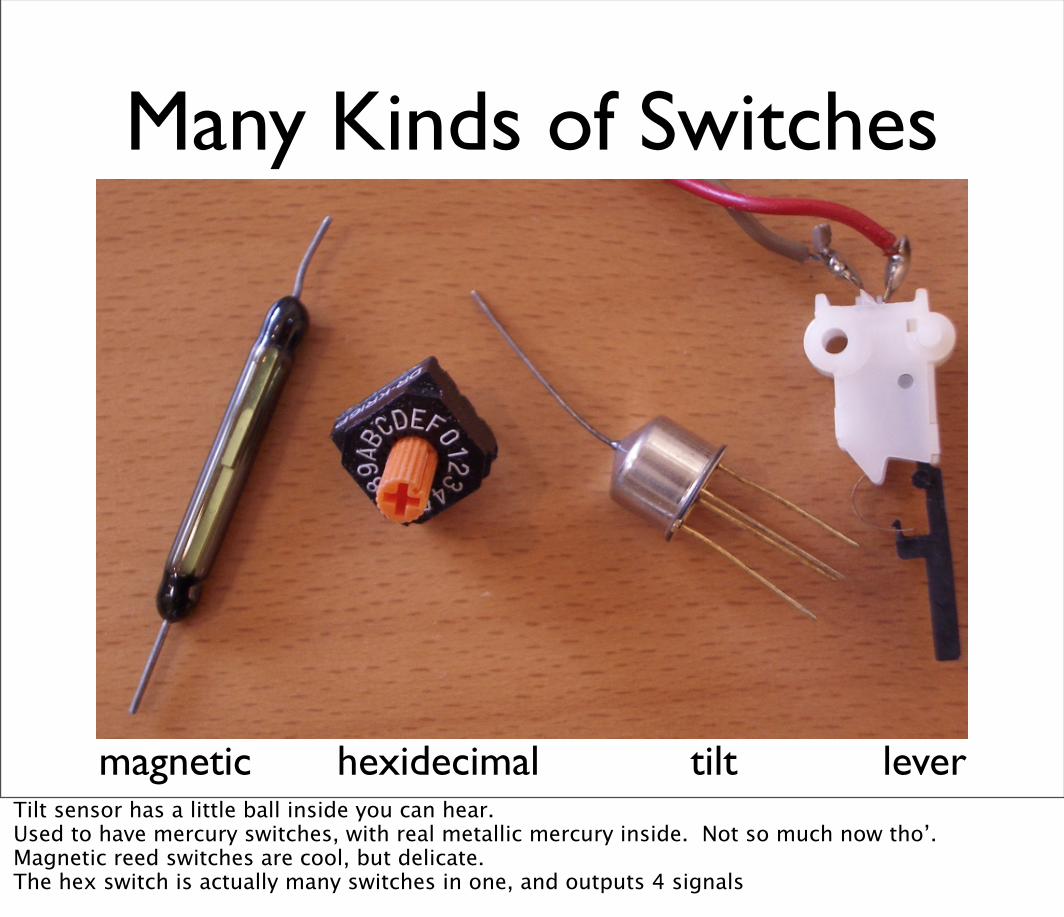
Many Kinds of Switches
magnetic tilt leverhexidecimalTilt sensor has a little ball inside you can hear.Used to have mercury switches, with real metallic mercury inside. Not so much now tho’.Magnetic reed switches are cool, but delicate.The hex switch is actually many switches in one, and outputs 4 signals

Tiny Switches
always connected together
connect when
pushed
Pressing the button, “closes the gap”
“gap”
These are the switches in your kit. One should have a slightly different button on it than the other.

Make Your Own Switches
• Anything that makes a connection
• Wires, tin foil, tinfoil balls, ball bearings
• Pennies!
• Nails, bolts, screws
• Or repurpose these tiny switches as bump detectors or closure detectors

Homemade Switches“Trick Penny”
Penny on a surface. When the penny is lifted, alarms go off

Homemade Switches“Trick Penny”
Wire soldered to penny.Wire looped or crimped to aluminum sheet.
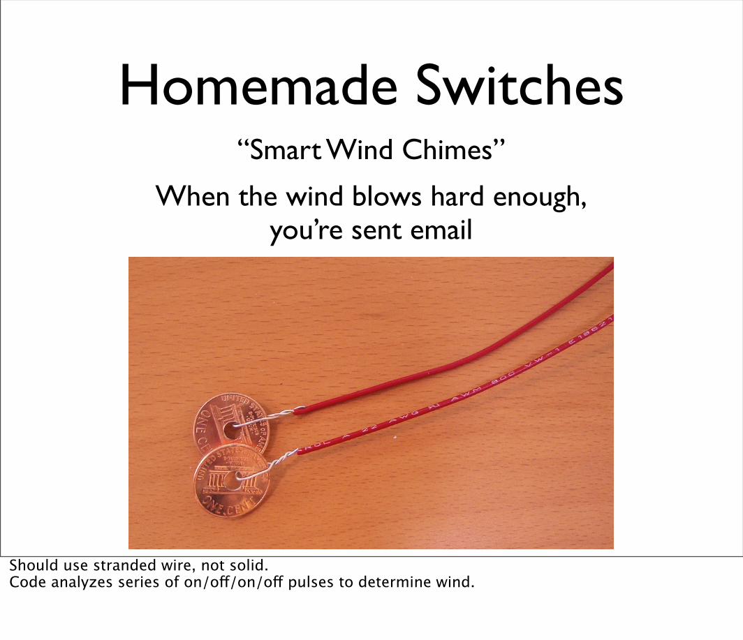
Homemade Switches“Smart Wind Chimes”
When the wind blows hard enough,you’re sent email
Should use stranded wire, not solid.Code analyzes series of on/off/on/off pulses to determine wind.

Digital Input
• Switches make or break a connection
• But Arduino wants to see a voltage
• Specifically, a “HIGH” (5 volts)
• or a “LOW” (0 volts)
How do you go from make/break to high/low?
HIGH
LOW

Switch to Volts: Positive Logic
“pull-down”
• Digital inputs can “float” between 0 and 5 volts
• Resistor “pulls down” input to ground (0 volts)
• Pressing switch sets input to 5 volts
• Press is HIGHRelease is LOW
Don’t want “pull-down” to be too small, or it uses a lot of current

Switch to Volts:Inverted Logic
• Resistor pulls up input to 5 volts
• Switch sets input to 0 volts
• But now the sense is inverted
• Press is LOW
• Release is HIGH “pull-up”
Inverted logic like this is common in microcontrollers

Arduino Digital Input
• Add switch circuit to any digital input (except pin 13)
• For output, use either existing pin 13 LED or wire up your own

Arduino Digital Input
Output is on-board pin 13 LED for nowUsing the fact that two of the switch leads are connected.Also, notice color coding. Blue is ground, purple is signalBut pin 13 LED is underneath! So gotta take a peak.

Making Jumper Wires• strip off about 1/2” of insulation
• Can use wire strippers, cutters, or fingers
• Can be a pain, so I have some pre-cut wires
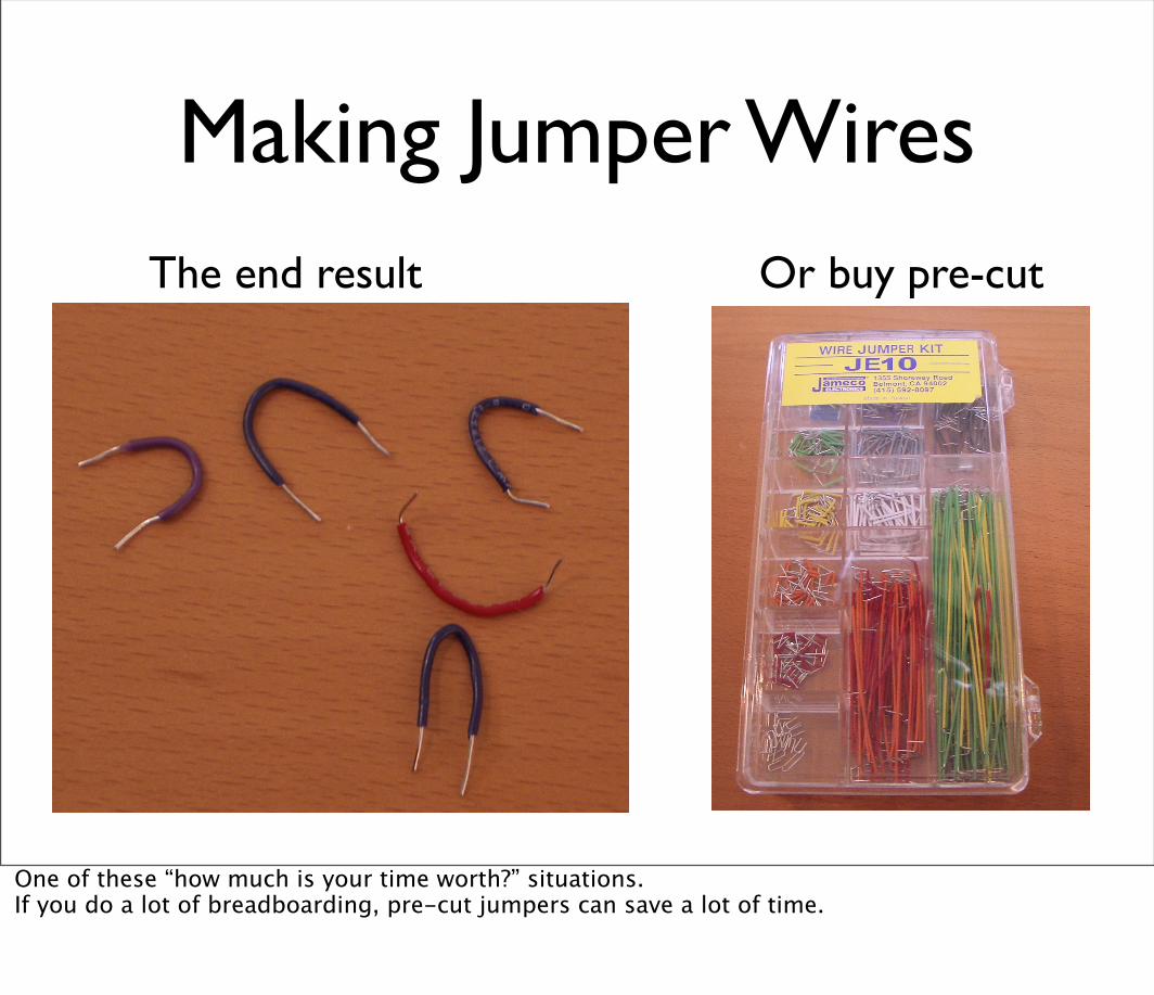
Making Jumper WiresThe end result Or buy pre-cut
One of these “how much is your time worth?” situations.If you do a lot of breadboarding, pre-cut jumpers can save a lot of time.

Using digitalRead()
• In setup(): use pinMode(myPin,INPUT)to make pin an input
• In loop(): use digitalRead(myPin) to get switch position
• If doing many tests, use a variable to hold the output value of digitalRead().
• e.g. val = digitalRead(myPin)
Enough with the atoms, back to the bits
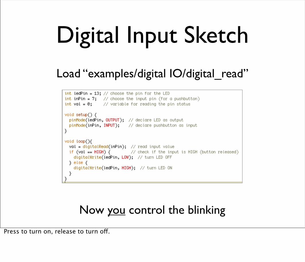
Digital Input Sketch
Now you control the blinking
Load “examples/digital IO/digital_read”
Press to turn on, release to turn off.
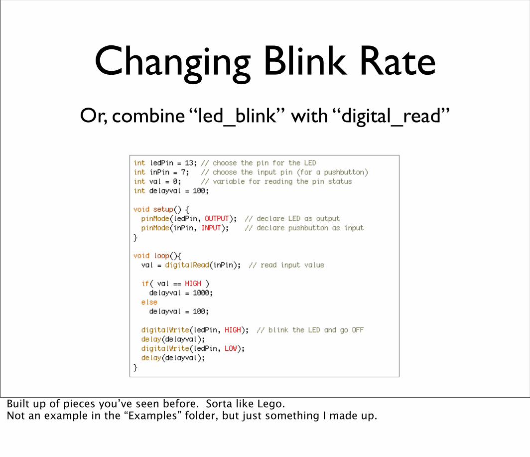
Changing Blink RateOr, combine “led_blink” with “digital_read”
Built up of pieces you’ve seen before. Sorta like Lego.Not an example in the “Examples” folder, but just something I made up.

Multiple Switches
Same sub-circuit,just duplicate
Can do lots of switches this way.

Multiple Switches
An example of how to lay it out. Don’t have to do it here. Try at home.I have extra 10k resistors.

Digital Input Uses
• spooky, remember?

Take a Break

Analog InputTo computers, analog is chunky
image from: http://www.engr.colostate.edu/~dga/me307/lectures.html

Analog Input
• Many states, not just two (HIGH/LOW)
• Number of states (or “bins”) is resolution
• Common computer resolutions:
• 8-bit = 256 states
• 16-bit = 65,536 states
• 32-bit = 4,294,967,296 states

Analog Input
• Arduino (ATmega8) has six ADC inputs
• (ADC = Analog to Digital Converter)
• Reads voltage between 0 to 5 volts
• Resolution is 10-bit (1024 states)
• In other words, 5/1024 = 4.8 mV smallest voltage change you can measure

Analog InputSure sure, but how to make a varying voltage?
With a potentiometer. Or just pot.
+5V–measure–
gnd–
Color coding: red goes to power, blue to ground, purple to ‘measure here’ (it’s a mix, see?)

PotentiometersMoving the knob is like moving
where the arrow taps the voltage on the resistor
And that’s actually how it works, btw, if you take apart a pot.But I might have the directions reversed (clockwise vs. anti-clockwise).

Arduino Analog Input
Red to Vcc
Purple to A0
Blue to Gnd
Hook it up, plug in the wires in directly“Vcc” is alias for +5V.“Raw” is alias for external power (approx 9V)
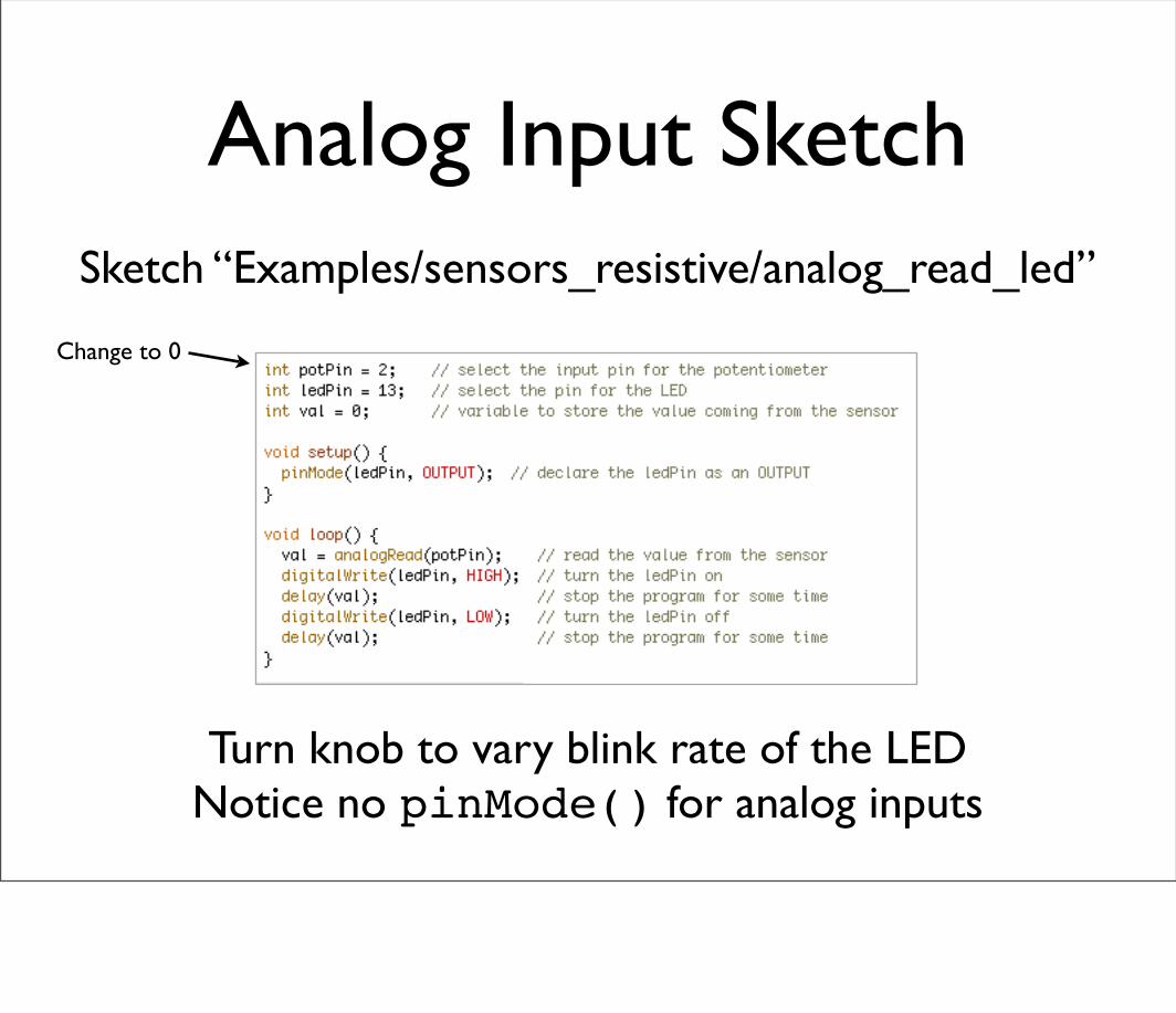
Analog Input SketchSketch “Examples/sensors_resistive/analog_read_led”
Turn knob to vary blink rate of the LEDNotice no pinMode() for analog inputs
Change to 0

What good are pots?
• Anytime you need a ranged input
• (we’re used to knobs)
• Measure rotational position
• steering wheel, etc.
• But more importantly for us, potentiometers are a good example of a resistive sensor

Sensing the Dark• Pots are example of a voltage divider
• Voltage divider splits a voltage in two
• Same as two resistors, but you can vary them

Sensing the Dark: Photocells
• aka. photoresistor, light-dependent resistor
• A variable resistor
• Brighter light == lower resistance
• Photocells you have range approx. 0-10k
schematic symbolPretty cheap too. Can get a grab bag of 100 misc from Jameco for $20

Photocell Circuit
pin A0
gnd
Vcc
Looks a lot like the pot circuit, doesn’t it?

Photocell Arduino Sketch
Can use as before, sketch “analog_read_led”
Wave your hand over it = blink fasterPoint it towards the light = blink slower
Change to 0
Just like magic!If circuit was configured the other way (photocell on bottom), then darkness would make it blink slower.

More Spooky, PleaseAll this blinking is okay, but...

Booo!
I designyour eyes
Okay, so the googly-eyeness of it makes it more Simpsonesque than spooky.

Evil Glowing Eyes
Almost as cool as Roy Batty

LED EyeballsLittle bit of hot glue and you’re set
Use your two orange LEDs
Use the two orange LEDs.Save the R,G,B LEDs for next week.Hot glue is the best thing in the world.I brought my hot glue gun if you want to do this right now
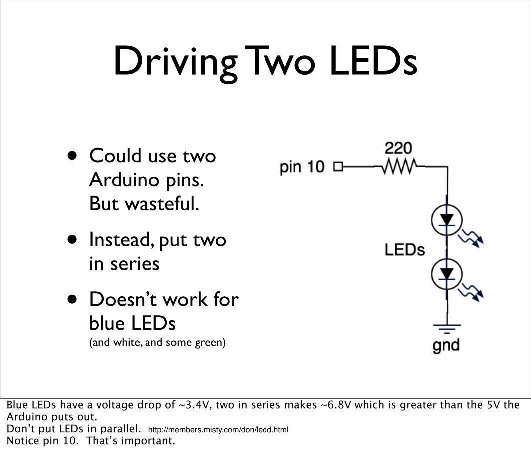
Driving Two LEDs
• Could use two Arduino pins. But wasteful.
• Instead, put two in series
• Doesn’t work for blue LEDs (and white, and some green)
Blue LEDs have a voltage drop of ~3.4V, two in series makes ~6.8V which is greater than the 5V the Arduino puts out.Don’t put LEDs in parallel. http://members.misty.com/don/ledd.htmlNotice pin 10. That’s important.

LED Eyes
photocell circuit is as beforeNotice, pin 10. This will become important later.
LED Eyes Brightness
• To complement analogRead(), there is analogWrite().
• Only available on digital pins 9,10,11. (yes, a little confusing)
• More next week about how it works.
• Can use it to set brightness of LEDs
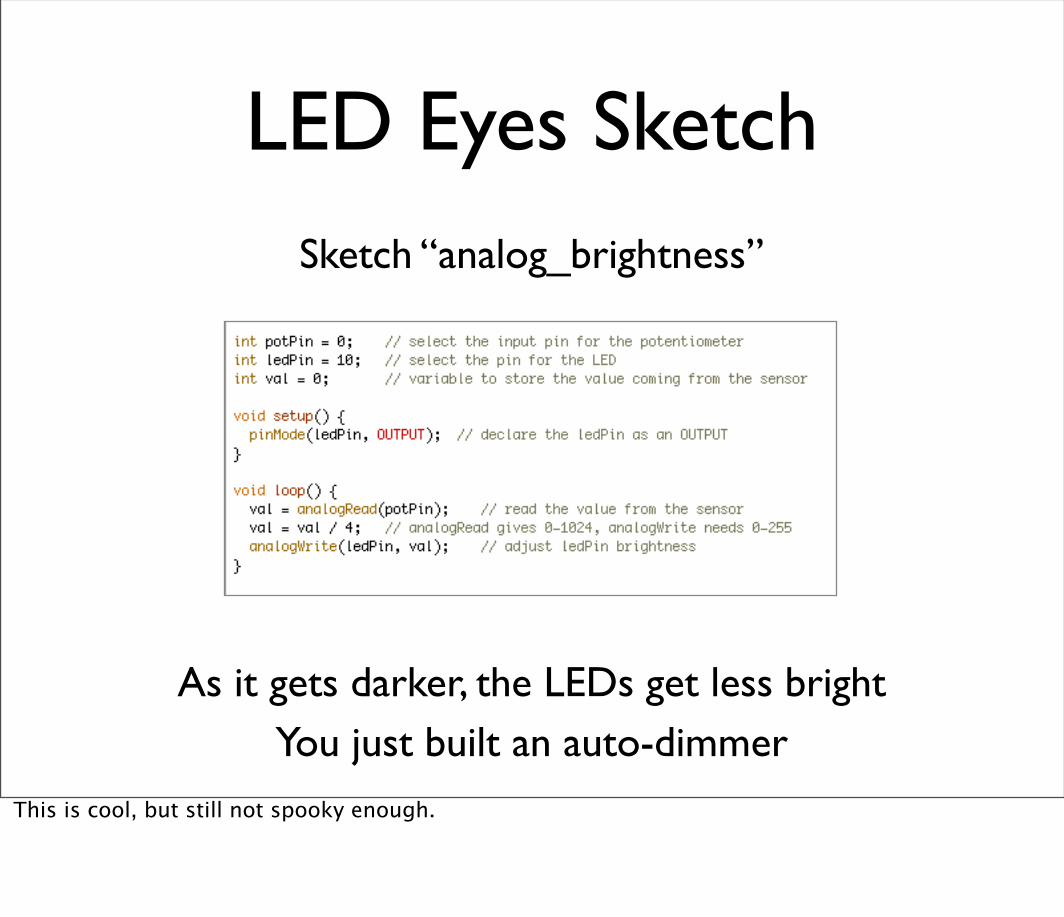
LED Eyes SketchSketch “analog_brightness”
As it gets darker, the LEDs get less brightYou just built an auto-dimmer
This is cool, but still not spooky enough.

Making Eyes Glow(where “glow” is the throbbing of brightness)
How does that glow throbbing work?
Sleeping laptops do something similar
Need to describe how brightness changes over time

LED Brightness Functions
time
brightness
Brightness over time can be described as a graph
Draw your graph, use the resulting numbers
100% on
off
Doesn’t matter which numbers you choose right now
LED Brightness Functions
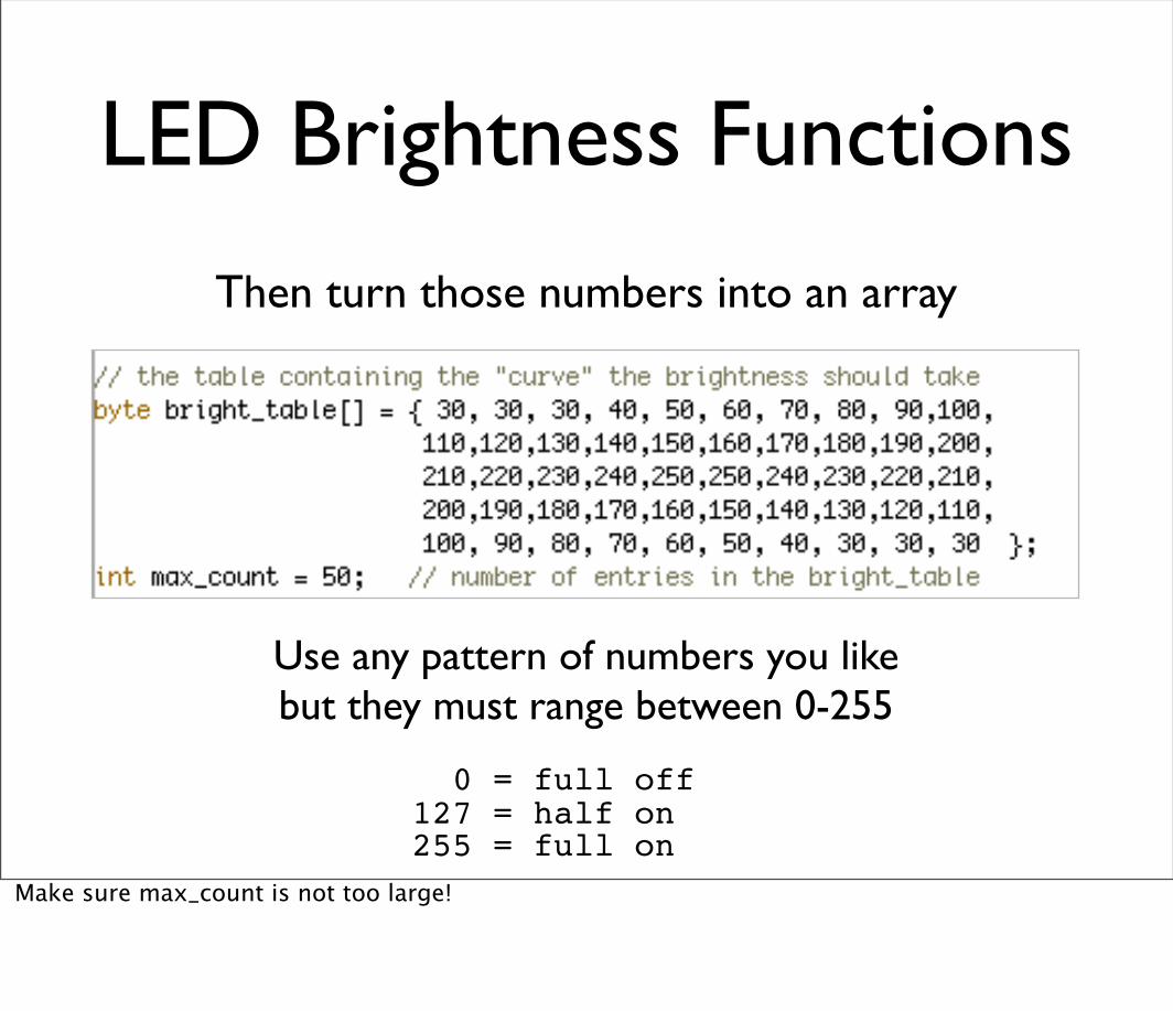
Then turn those numbers into an array
Use any pattern of numbers you likebut they must range between 0-255
0 = full off127 = half on255 = full on
Make sure max_count is not too large!

LED Brightness FunctionsOnce you have your table...
1. Get a bright_table value2. Send it out with analogWrite()3. Advance counter into bright_table4. Wait a bit5. Repeat
...the rest is just programming
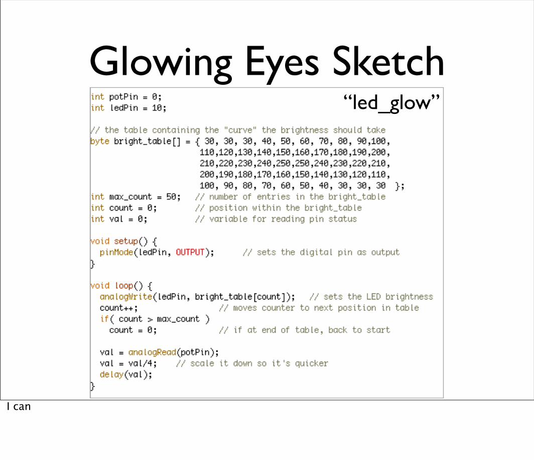
Glowing Eyes Sketch“led_glow”
I can

Glowing Eyes

Going Further
• Glowing LEDs
• The last sketch is data driven
• So you can plug in any brightness function
• Make a flickering candle or a bad neon light
Going Further
• Photocells
• Think of some interesting uses
• What about multiple photocells?
• Homemade Sensors
• Make some of your own!

Next Week
• Motion with Servos
• R,G,B color mixing for mood lighting
• Controlling Arduino from a computer
• Controlling a computer from Arduino

Tod E. Kurt
END Class 2
http://todbot.com/blog/spookyarduino