Spectacular Assay results for First RC Hole at Lindi Jumbo
12
1 | Page Spectacular Assay results for First RC Hole at Lindi Jumbo Highlights 04 November 2015 Overview Perth-based African-focussed junior explorer Walkabout Resources (ASX:WKT) is pleased to report on initial assay results for RC drilling at site in south eastern Tanzania. Results for RC hole No. LJRC001 have been received. Hole LJRC001 is located at the northern extension of the Gilbert Arc and within the strong VTEM signature that defines the rest of the antiform structure. Hole No. LJRC016 was drilled slightly further north to define the down-dip extension of hole LJRC001 but the assay results for hole LJRC016 have not yet been received. Intercept lengths are measured downhole and true widths are not yet reported. Allan Mulligan, Managing Director of Walkabout commented, “These initial results are spectacular and considering the extent of massive graphite observed throughout the Gilbert Arc, we are hopeful that there could be an extensive high-grade orebody within the structure. This would vindicate our strategy to focus on defining a high-grade orebody for fast-tracked development of the first mining module. The next batch of assays for 4 holes are now being processed at the laboratory.” Assay results for first RC hole LJRC001 received Hole No. LJRC001 assayed at 20m @ 12.65% TGC including 8m @ 22.71% TGC Second zone of graphite biotite schist assayed at 15m @ 4.72% TGC including 9m @ 6.03% TGC Hole LJRC001 drilled on the VTEM signature that defined the Gilbert Arc where extensive visually defined massive graphite intercepts where reported LJRC001 makes up the northern extension of Gilbert Arc antiformal structure
Transcript of Spectacular Assay results for First RC Hole at Lindi Jumbo

1 | P a g e
Spectacular Assay results for First RC Hole at Lindi Jumbo
Highlights 04 November 2015
Overview
Perth-based African-focussed junior explorer Walkabout Resources (ASX:WKT) is pleased to report on initial assay results for RC drilling at site in south eastern Tanzania.
Results for RC hole No. LJRC001 have been received. Hole LJRC001 is located at the northern extension of the Gilbert Arc and within the strong VTEM signature that defines the rest of the antiform structure. Hole No. LJRC016 was drilled slightly further north to define the down-dip extension of hole LJRC001 but the assay results for hole LJRC016 have not yet been received.
Intercept lengths are measured downhole and true widths are not yet reported.
Allan Mulligan, Managing Director of Walkabout commented, “These initial results are spectacular and considering the extent of massive graphite observed throughout the Gilbert Arc, we are hopeful that there could be an extensive high-grade orebody within the structure.
This would vindicate our strategy to focus on defining a high-grade orebody for fast-tracked development of the first mining module. The next batch of assays for 4 holes are now being processed at the laboratory.”
Assay results for first RC hole LJRC001 received
Hole No. LJRC001 assayed at 20m @ 12.65% TGC including 8m @ 22.71% TGC
Second zone of graphite biotite schist assayed at 15m @ 4.72% TGC including 9m @ 6.03% TGC
Hole LJRC001 drilled on the VTEM signature that defined the Gilbert Arc where extensive visually defined massive graphite intercepts where reported
LJRC001 makes up the northern extension of Gilbert Arc antiformal structure

2 | P a g e
HoleFrom
(m)
To
(m)
Width
(m)Lithology
Total Graphitic
Carbon TGC%
Notable
Intersections
TGC%
Notable
Intersections 2
TGC%
LJRC001 12 13 1 Graphite Schist 5.50
13 14 1 Graphite Schist 5.44
14 15 1 Graphite Schist 13.90
15 16 1 Graphite Schist 19.80
16 17 1 Graphite Schist 1.92
17 18 1 Graphite Schist 1.32
18 19 1 Graphite Biotite Gneiss 17.00 1 m @ 17
19 20 1 Graphite Biotite Gneiss 2.84
20 21 1 Graphite Biotite Gneiss 2.40
21 22 1 Graphite Biotite Gneiss 0.13
22 23 1 Graphite Biotite Gneiss 0.07
23 24 1 Graphite Biotite Gneiss 0.92
24 25 1 Graphite Biotite Gneiss 13.10
25 26 1 Graphite Biotite Gneiss 31.90
26 27 1 Graphite Biotite Gneiss 21.30
27 28 1 Graphite Biotite Gneiss 15.10
28 29 1 Graphite Biotite Gneiss 25.40
29 30 1 Graphite Biotite Gneiss 25.20
30 31 1 Graphite Biotite Gneiss 25.20
31 32 1 Graphite Biotite Gneiss 24.50
Not sampled 10m Break
41 42 1 Graphite Biotite Schist 7.88
42 43 1 Graphite Biotite Schist 7.21
43 44 1 Graphite Biotite Schist 7.25
44 45 1 Graphite Biotite Schist 5.37
45 46 1 Graphite Biotite Schist 4.70
46 47 1 Graphite Biotite Schist 5.17
47 48 1 Graphite Biotite Schist 4.62
48 49 1 Graphite Biotite Schist 6.39
49 50 1 Graphite Biotite Schist 5.72
50 51 1 Graphite Biotite Schist 2.87
51 52 1 Graphite Biotite Schist 0.40
52 53 1 Graphite Biotite Schist 3.37
53 54 1 Graphite Biotite Schist 4.74
54 55 1 Graphite Biotite Schist 4.55
55 56 1 Graphite Biotite Schist 0.60
Coded Colours
TGC % Range
5 to 9.9
10 to 19.9
>20
0 to 4.9
4m @ 11.16
including 2m @
16.85
8m @ 22.71
9m @ 6.03
including 3m @
7.45
20m @ 12.65
15m @ 4.72
Assay Report
The assay results for the first RC hole completed at Lindi Jumbo Graphite Project, LJRC001, have been received from the accredited assay laboratory in Perth. The drill chips for this hole were shipped immediately upon its completion as a result of available transport. The drill chips were first despatched to a sample preparation laboratory in Mwanza, Tanzania and then the pulps were exported to Perth, Australia.
Table 1: Assay results for hole LJRC001 reported individually at 1m intervals

3 | P a g e
The valuation methodology employed for all RC pulps is;
Dry, crush to 75% passing 2 mm, split, pulverize <1.5 kg to 85% passing 75 um
Graphitic Carbon, HNO3 leach, LECO
Ash and total digest of carbon samples for multi element
Solution from the above DIA40Q digest is presented to an ICP-OES for the quantification of the elements of Interest (V)
A section through drill holes LJRC001and LJRC016 illustrated in figure 2 below highlights the potential amenability of the wide, shallow structure to open-cut mining.
Figure 1: The location of RC drill hole LJRC001 showing the extension to the Gilbert Arc antiform structure.

4 | P a g e
Figure 2: Section A-B across holes LJRC001 and LJRC016
Lindi Jumbo Graphite Project
Walkabout intends to fast track the exploration at Lindi Jumbo to validate the deposit, graphite grade, concentrate product grade and flake size distribution. These results will enable the early introduction of an end-user market partner to secure product off-take and clarify operational right-sizing.
A small, high grade and functional Resource of between 8 to 12 million tonnes will be adequate to plan a first stage modular mining operation and initiate partnership discussions with an end-user group.
Details of Walkabout Resources’ other projects are available at the Company’s website, www.wkt.com.au
ENDS For further information contact: Allan Mulligan – Managing Director +61 8 6298 7500 (T) [email protected]
LINDI JUMBO PROJECT - GEOLOGY
5 | P a g e
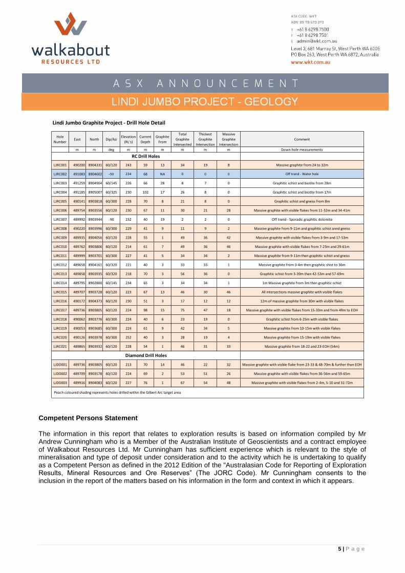
Lindi Jumbo Graphite Project - Drill Hole Detail
Hole
NumberEast North Dip/Azi
Elevation
(RL's)
Current
Depth
Graphite
From
Total
Graphite
Intersected
Thickest
Graphite
Intersection
Massive
Graphite
Intersection
Comment
m m deg m m m m m m Down-hole measurements
LJRC001 490200 8904331 60/120 243 59 13 34 19 8 Massive graphite from 24 to 32m
LJRC002 491083 8904602 -90 234 68 NA 0 0 0 Off trend - Water hole
LJRC003 491259 8904904 60/145 226 66 28 8 7 0 Graphitic schist and biotite from 28m
LJRC004 491185 8905007 60/325 230 102 17 26 8 0 Graphitic schist and biotite from 17m
LJRC005 490141 8903818 60/300 228 70 8 21 8 0 Graphitic schist and gneiss from 8m
LJRC006 489754 8903556 60/120 230 67 11 30 21 28 Massive graphite with visible flakes from 11-32m and 34-41m
LJRC007 489992 8903944 -90 232 40 19 2 2 0 Off trend - Sporadic graphitic dolomite
LJRC008 490220 8903996 60/300 229 41 9 11 9 2 Massive graphite from 9-11m and graphitic schist annd gneiss
LJRC009 489935 8904056 60/120 228 55 1 49 36 42 Massive graphite with visible flakes from 3-9m and 17-53m
LJRC010 489762 8903806 60/120 214 61 7 49 36 46 Massive graphite with visible flakes from 7-23m and 29-61m
LJRC011 489999 8903701 60/300 227 41 5 34 34 2 Massive graphite from 9-11m then graphitic schist and gneiss
LJRC012 489658 8904161 60/320 221 40 3 33 33 1 Massive graphite from 3-4m then graphitic shist to 36m
LJRC013 489858 8903935 60/320 218 70 3 56 36 0 Graphitic schist from 3-39m then 42-53m and 57-69m
LJRC014 489795 8902800 60/145 234 65 3 34 34 1 1m Massive graphite from 3m then graphitic schist
LJRC015 489707 8903728 60/120 223 67 13 46 30 46 All intersections massive graphite with visible flakes
LJRC016 490172 8904373 60/120 230 51 3 17 12 12 12m of massive graphite from 30m with visible flakes
LJRC017 489736 8903805 60/120 224 98 15 75 47 18 Massive graphite with visible flakes from 15-33m and from 49m to EOH
LJRC018 490062 8903776 60/300 224 40 6 23 19 0 Graphitic schist from 6-25m with visible flakes
LJRC019 490053 8903685 60/300 224 61 9 42 34 5 Massive graphite from 10-15m with visible flakes
LJRC020 490126 8903978 60/300 252 40 3 28 19 4 Massive graphite from 15-19m with visible flakes
LJRC021 489865 8903932 60/120 228 54 1 46 31 33 Massive graphite from 18-22 and 23-EOH (54m)
LJDD001 489736 8903805 60/120 213 70 14 46 22 32 Massive graphite with visible flake from 23-33 & 48-70m & further than EOH
LJDD002 489709 8903578 60/120 224 69 2 53 51 26 Massive graphite with visible flakes from 36-56m and 59-65m
LJDD003 489916 8904083 60/120 227 76 1 67 54 48 Massive graphite with visible flakes from 2-4m, 5-10 and 31-72m
RC Drill Holes
Diamond Drill Holes
Peach coloured shading represents holes drilled within the Gilbert Arc target area
Competent Persons Statement The information in this report that relates to exploration results is based on information compiled by Mr Andrew Cunningham who is a Member of the Australian Institute of Geoscientists and a contract employee of Walkabout Resources Ltd. Mr Cunningham has sufficient experience which is relevant to the style of mineralisation and type of deposit under consideration and to the activity which he is undertaking to qualify as a Competent Person as defined in the 2012 Edition of the "Australasian Code for Reporting of Exploration Results, Mineral Resources and Ore Reserves” (The JORC Code). Mr Cunningham consents to the inclusion in the report of the matters based on his information in the form and context in which it appears.

6 | P a g e
JORC Code, 2012 Edition – Table 1 report template
Section 1 Sampling Techniques and Data
(Criteria in this section apply to all succeeding sections.)
Criteria JORC Code explanation Commentary
Sampling techniques
Nature and quality of sampling (eg cut channels, random chips, or specific specialised industry standard measurement tools appropriate to the minerals under investigation, such as down hole gamma sondes, or handheld XRF instruments, etc). These examples should not be taken as limiting the broad meaning of sampling.
Include reference to measures taken to ensure sample representivity and the appropriate calibration of any measurement tools or systems used.
Aspects of the determination of mineralisation that are Material to the Public Report.
In cases where ‘industry standard’ work has been done this would be relatively simple (eg ‘reverse circulation drilling was used to obtain 1 m samples from which 3 kg was pulverised to produce a 30 g charge for fire assay’). In other cases more explanation may be required, such as where there is coarse gold that has inherent sampling problems. Unusual commodities or mineralisation types (eg submarine nodules) may warrant disclosure of detailed information.
Reverse Circulation (RC) drilling was done and samples were split using a cone splitter into 1m samples. All primary samples as well as sample spoils are weighed and the results recorded.
All RC intervals were geologically logged by a suitably qualified geologist and mineralized intersects (graphitic zones) dispatched to SGS in Mwanza Tanzania for processing.
Graphite quality and rock classifications were visually determined by field geologist.
Drilling techniques
Drill type (eg core, reverse circulation, open-hole hammer, rotary air blast, auger, Bangka, sonic, etc) and details (eg core diameter, triple or standard tube, depth of diamond tails, face-sampling bit or other type, whether core is oriented and if so, by what method, etc).
Drilling was conducted by Kuchimba Tanzania Drilling. RC drilling was by a Hydco track mounted 450 rig using a Sullair compressor with air capacity 900CFM/350 PSI, and auxiliary Sullair air compressor with air capacity 900CFM/350 PSI and a booster with 1800CFM/1000 PSI. Drilling was conducted with a 7 ½” face sampling bit.
Drill sample recovery
Method of recording and assessing core and chip sample recoveries and results assessed.
Measures taken to maximise sample recovery and ensure representative nature of the samples.
RC recovery was recorded by visual estimation of recovered sample bags and all sample rejects from the splitter were weighed and the weights recorded. All A and B samples were weighed to assess the accuracy of the sampling process.

7 | P a g e
Criteria JORC Code explanation Commentary
Whether a relationship exists between sample recovery and grade and whether sample bias may have occurred due to preferential loss/gain of fine/coarse material.
Recovery was generally of good quality.
Logging Whether core and chip samples have been geologically and geotechnically logged to a level of detail to support appropriate Mineral Resource estimation, mining studies and metallurgical studies.
Whether logging is qualitative or quantitative in nature. Core (or costean, channel, etc) photography.
The total length and percentage of the relevant intersections logged.
All drillholes were geologically logged in full by an independent geologist.
All data is initially captured on paper logging sheets, and transferred to pre-formatted excel tables and loaded into the project specific drillhole database.
The logging and reporting of visual graphite percentages on preliminary logs
is semi‐quantitative. A reference to previous logs and assays is used as a reference.
All logs are checked and validated by an external geologist before loading into the database. Logging is of sufficient quality for current studies.
Sub-sampling techniques and sample preparation
If core, whether cut or sawn and whether quarter, half or all core taken.
If non-core, whether riffled, tube sampled, rotary split, etc and whether sampled wet or dry.
For all sample types, the nature, quality and appropriateness of the sample preparation technique.
Quality control procedures adopted for all sub-sampling stages to maximise representivity of samples.
Measures taken to ensure that the sampling is representative of the in situ material collected, including for instance results for field duplicate/second-half sampling.
Whether sample sizes are appropriate to the grain size of the material being sampled.
Reverse Circulation (RC) samples were split using a cone splitter into 1m samples. All primary samples and RC spoils were weighed and the results recorded. All samples were dry.
Duplicate samples were taken approximately 1:20 and were collected by spearing approximately 3kg from the representative 1m interval sample reject.
QC measures include field duplicate samples, blanks and certified standards (1:20) over and above the internal controls at SGS.
All sampling was carefully supervised. Ticket books were used with pre-numbered tickets placed in the sample bag and double checked against the ticket stubs and field sample sheet to guard against sample mix ups.
All RC intervals were geologically logged and mineralized intersects dispatched to SGS in Mwanza for sample preparation, and subsequently to Perth for assaying of pulps.
All samples were separately crushed and pulverized to 75% passing 2 mm, split, pulverize <1.5 kg to 85% passing 75 um.
Graphitic Carbon Leco Method by CSA05V (0.01% lower detection and 40% upper detection limit), HNO3 leach,

8 | P a g e
Criteria JORC Code explanation Commentary
LECO Ash and total digest of carbon samples for multi element. The solution from the above DIA40Q digest is presented to an ICP-OES for the quantification of the elements of Interest (V) with 1 ppm lower detection limit and a 10,000ppm upper limit.
Quality of assay data and laboratory tests
The nature, quality and appropriateness of the assaying and laboratory procedures used and whether the technique is considered partial or total.
For geophysical tools, spectrometers, handheld XRF instruments, etc, the parameters used in determining the analysis including instrument make and model, reading times, calibrations factors applied and their derivation, etc.
Nature of quality control procedures adopted (eg standards, blanks, duplicates, external laboratory checks) and whether acceptable levels of accuracy (ie lack of bias) and precision have been established.
QC measures include duplicate samples, blanks and certified standards (1:20) over and above the internal controls at SGS.
Verification of sampling and assaying
The verification of significant intersections by either independent or alternative company personnel.
The use of twinned holes.
Documentation of primary data, data entry procedures, data verification, data storage (physical and electronic) protocols.
Discuss any adjustment to assay data.
An external geological consultant conducted a site visit in September 2015 during the drilling program to observe all drilling and sampling procedures. All procedures were considered industry standard, well supervised and well carried out.
All data is initially captured on paper logging sheets, and transferred to pre-formatted excel tables and loaded into the project specific drillhole database. Paper logs are scanned and stored on the companies server. Original logs are stored at a secure facility in Dar Es Salaam.
Assay data is provided as .csv files from the laboratory and entered into the project specific drillhole database. Spot checks are made against the laboratory certificates.
Location of data points
Accuracy and quality of surveys used to locate drill holes (collar and down-hole surveys), trenches, mine workings and other locations used in Mineral Resource estimation.
Specification of the grid system used.
Collar positions were set out using a handheld Garmin GPS with reported accuracy of 5m and reported using WGS84, SUTM Zone 37.
Three pegs were lined up using a Suunto compass and a rope laid out on the

9 | P a g e
Criteria JORC Code explanation Commentary
Quality and adequacy of topographic control.
ground between the three pegs to align the rig. Once the drilling was complete the final collar position was recorded using a handheld Garmin GPS.
Downhole surveys (dip and azimuth) were taken using a Reflex electronic multi shot instrument.
An accurate collar position survey has been commissioned using a licensed independent surveyor but has not yet been received.
Data spacing and distribution
Data spacing for reporting of Exploration Results.
Whether the data spacing and distribution is sufficient to establish the degree of geological and grade continuity appropriate for the Mineral Resource and Ore Reserve estimation procedure(s) and classifications applied.
Whether sample compositing has been applied.
Drillholes were to test pre-determined geophysical targets and are thus not on a pre-determined grid.
The drilling is at exploration level with some areas having 10-70m holes spaced along sections and lines spaced between 100m and 350m apart.
No sample compositing has been done.
Orientation of data in relation to geological structure
Whether the orientation of sampling achieves unbiased sampling of possible structures and the extent to which this is known, considering the deposit type.
If the relationship between the drilling orientation and the orientation of key mineralised structures is considered to have introduced a sampling bias, this should be assessed and reported if material.
Surface mapping and interpretation of the VTEM data shows that the lithologies dip between 30 and 50 degrees to both the NW and SE on the limbs of various synforms in the area.
Drillholes were planned to intersect the lithology/mineralisation at right angles.
Sample security
The measures taken to ensure sample security.
Samples were split and sealed (tied off in calico or plastic bags) at the drill site and transported to the Exploration Camp for processing. All samples picked for analyses are placed in clearly marked polyweave bags (10 per bag), and were stored securely on site before transported via a courier company to SGS in Mwanza.
Audits or reviews
The results of any audits or reviews of sampling techniques and data.
An external geological consultant conducted a site visit in September 2015 during the drilling program to observe all drilling and sampling procedures. All procedures were considered industry standard, well supervised and well carried out.

10 | P a g e
Section 2 Reporting of Exploration Results
(Criteria listed in the preceding section also apply to this section.) Criteria JORC Code explanation Commentary
Mineral tenement and land tenure status
Type, reference name/number, location and ownership including agreements or material issues with third parties such as joint ventures, partnerships, overriding royalties, native title interests, historical sites, wilderness or national park and environmental settings.
The security of the tenure held at the time of reporting along with any known impediments to obtaining a licence to operate in the area.
The drilling was located on one granted Exploration License (PL9992/2014). Walkabout is earning 70% interest in the tenure.
The company is not aware of any impediments relating to the licenses or area.
Exploration done by other parties
Acknowledgment and appraisal of exploration by other parties.
As far as the company is aware no exploration for graphite has been done by other parties in this area. Some gemstone diggings for tourmaline are present in the PL.
Geology Deposit type, geological setting and style of mineralisation.
The project area is situated in the Usagaran of the Mozambique belt and consists of graphitic gneisses and schists interpreted to occur along the flanks of various synforms in the area with the lithological units dipping at between 30 and 50 degrees to the NW and SE.
Drill hole Information
A summary of all information material to the understanding of the exploration results including a tabulation of the following information for all Material drill holes: o easting and northing of the drill hole
collar o elevation or RL (Reduced Level –
elevation above sea level in metres) of the drill hole collar
o dip and azimuth of the hole o down hole length and interception
depth o hole length.
If the exclusion of this information is justified on the basis that the information is not Material and this exclusion does not detract from the understanding of the report, the Competent Person should clearly explain why this is the case.
Drillhole coordinates and orientations are provided in Table 1 of this report.
This statement relates to Exploration Results.
Data In reporting Exploration Results, All 1m sample results are reported

11 | P a g e
Criteria JORC Code explanation Commentary
aggregation methods
weighting averaging techniques, maximum and/or minimum grade truncations (eg cutting of high grades) and cut-off grades are usually Material and should be stated.
Where aggregate intercepts incorporate short lengths of high grade results and longer lengths of low grade results, the procedure used for such aggregation should be stated and some typical examples of such aggregations should be shown in detail.
The assumptions used for any reporting of metal equivalent values should be clearly stated.
individually in Table 1 without a cutoff applied where sampling has been conducted.
Aggregate graphite intersections are quoted using a cutoff of 5% TG and were averaged as all sample intervals are equal.
No metal equivalent values have been reported.
Relationship between mineralisation widths and intercept lengths
These relationships are particularly important in the reporting of Exploration Results.
If the geometry of the mineralisation with respect to the drill hole angle is known, its nature should be reported.
If it is not known and only the down hole lengths are reported, there should be a clear statement to this effect (eg ‘down hole length, true width not known’).
The drilling is at right angles to the mapped strike of the outcropping lithologies.
All intercepts are reported as down-hole lengths and are aimed at being as perpendicular to mineralisation as practical.
Diagrams Appropriate maps and sections (with scales) and tabulations of intercepts should be included for any significant discovery being reported These should include, but not be limited to a plan view of drill hole collar locations and appropriate sectional views.
A drillhole plan is provided in Figures 1 and 2.
Balanced reporting
Where comprehensive reporting of all Exploration Results is not practicable, representative reporting of both low and high grades and/or widths should be practiced to avoid misleading reporting of Exploration Results.
All 1m sample results are reported individually
Other substantive exploration data
Other exploration data, if meaningful and material, should be reported including (but not limited to): geological observations; geophysical survey results; geochemical survey results; bulk samples – size and method of treatment; metallurgical test results; bulk density, groundwater, geotechnical and rock characteristics; potential deleterious or contaminating substances.
Previous announcements include the release of assay data related to surface “dig and grab” samples (ASX: 14 May 2015) and also to the results of an Airborne VTEM Survey (ASX: 19 September 2015).
Graphite characterization Petrography results(ASX: 30 July 2015), and initial metallurgy (ASX: 3 June 2015).

12 | P a g e
Criteria JORC Code explanation Commentary
Further work The nature and scale of planned further work (eg tests for lateral extensions or depth extensions or large-scale step-out drilling).
Diagrams clearly highlighting the areas of possible extensions, including the main geological interpretations and future drilling areas, provided this information is not commercially sensitive.
Exploration drilling is ongoing. Further holes are planned to test targets generated through the VTEM survey and surface mapping with the aim of delineating a maiden resource.