LINDI JUMBO PROJECT - GEOLOGY For personal use only · 1/19/2016 · the minerals industry that...
21
1 | Page LINDI JUMBO PROJECT - GEOLOGY Maiden JORC Resource at Lindi Jumbo Graphite Project Highlights 19 January 2016 Overview Emerging African graphite producer Walkabout Resources Ltd (ASX:WKT) is pleased to announce the Maiden JORC Inferred Resource at the Lindi Jumbo Graphite Project in south eastern Tanzania. The JORC 2012 Inferred Resource was calculated by Trepanier Pty Ltd, an independent geological consultancy. Managing Director of Walkabout Resources Ltd, Allan Mulligan commented; “There’s a phrase in the minerals industry that “grade is king”. The multiple and discrete domains of this exciting Resource should provide the flexibility and robustness to a potential mining operation that will give the Lindi Jumbo Project a huge advantage. The possible option of mining substantially higher grade zones during periods of economic downturn as opposed to being locked in to a grade of around 5% are huge project enablers. We remain confident that the resource size is adequate and in line with our prudent and risk-averse development approach for a modular first stage operation. The technical studies will now commence in earnest.” The Gilbert Arc Inferred JORC Mineral Resource estimated at 15.3m tonnes at 10.1% TGC for contained flake graphite of 1,542,000 tonnes Low grade portion of Inferred Resource (Domain 4) in a separate location and can be excluded altogether High grade core of 2.6m tonnes at 20.6% TGC is enveloped by 6.9m tonnes at 8.9% TGC possibly allowing for discrete and flexible mining practices Resource includes vanadium component of 11.7m tonnes at 0.19% V 2 O 5 Resource estimate covers only a very small footprint area of Lindi Jumbo Graphite Project Under terms of MOU, publishing of Inferred Resource earns Walkabout 70% holding of tenement package For personal use only
Transcript of LINDI JUMBO PROJECT - GEOLOGY For personal use only · 1/19/2016 · the minerals industry that...

1 | P a g e
LINDI JUMBO PROJECT - GEOLOGY
Maiden JORC Resource at Lindi Jumbo Graphite Project
Highlights 19 January 2016
Overview Emerging African graphite producer Walkabout Resources Ltd (ASX:WKT) is pleased to announce
the Maiden JORC Inferred Resource at the Lindi Jumbo Graphite Project in south eastern
Tanzania. The JORC 2012 Inferred Resource was calculated by Trepanier Pty Ltd, an independent
geological consultancy.
Managing Director of Walkabout Resources Ltd, Allan Mulligan commented; “There’s a phrase in
the minerals industry that “grade is king”. The multiple and discrete domains of this
exciting Resource should provide the flexibility and robustness to a potential mining
operation that will give the Lindi Jumbo Project a huge advantage.
The possible option of mining substantially higher grade zones during periods of economic
downturn as opposed to being locked in to a grade of around 5% are huge project enablers.
We remain confident that the resource size is adequate and in line with our prudent and
risk-averse development approach for a modular first stage operation. The technical
studies will now commence in earnest.”
The Gilbert Arc Inferred JORC Mineral Resource estimated at 15.3m tonnes at
10.1% TGC for contained flake graphite of 1,542,000 tonnes
Low grade portion of Inferred Resource (Domain 4) in a separate location and can be excluded altogether
High grade core of 2.6m tonnes at 20.6% TGC is enveloped by 6.9m tonnes at 8.9% TGC possibly allowing for discrete and flexible mining practices
Resource includes vanadium component of 11.7m tonnes at 0.19% V2O5
Resource estimate covers only a very small footprint area of Lindi Jumbo Graphite Project
Under terms of MOU, publishing of Inferred Resource earns Walkabout 70% holding of tenement package
For
per
sona
l use
onl
y

2 | P a g e
Resource Statement
Category Domain
Tonnes
(millions)
TGC
(%)
V2O5
(%)
Contained
TGC (t)
Contained
V2O5 (t)
Inferred 1 6.9 8.9 0.19 611,000 13,000
Inferred 21 2.6 20.6 0.20 526,500 5,200
Inferred 3 2.2 11.7 0.19 258,500 4,300
Inferred 42 3.7 3.9 0.04 146,000 1,600
Inferred ALL 15.3 10.1 0.16 1,542,000 24,100
Inferred Excluding Domain 4
11.7 11.9 0.19 1,396,000 22,500
1 High grade core enveloped by Domain 1
2 Low grade domain (eastern flank of The Gilbert Arc)
Note: Appropriate rounding applied
The Directors of Walkabout Resources Ltd are extremely pleased with the publication of this
maiden JORC Inferred Resource. The shallow, very high grade nature of the mineralization, the
high ratio of large and jumbo flakes reported during the initial float testwork at a coarse grind (83.4
% @ 850µ) the high recoveries (>98%) and a concentrate grade of 95.7% TGC achieved through
a standard and simple floatation regime support the Company’s opinion that the deposit has the
potential for eventual economic extraction.
In terms of upgrade potential, the Mineral Resource has utilised less than 1% of the tenement
package area of 325 sq. kilometres and much upside exists for further upgrade. Previous work
across the tenement package has returned several surface samples with graphite assays in
excess of 10% TGC and up to 23% TGC. These areas will be further explored, in conjunction with
the VTEM data to source further high grade, large flake deposits within the tenement package.
The oxide zone capping the Gilbert Arc Resource is relatively thin (<10m) and shallow and initial
metallurgical work has not highlighted potential extraction issues of the oxide material.
The high grade core of Domain 2 at 20.6% TGC in enveloped inside a wide, shallow package of
almost 7 million tonnes at a grade of 8.9% TGC. This infers that mining operations will be shallow,
discrete and possibly able to selectively produce a run of mine product at or near planning
specification.
The development strategy adopted by the Board envisages a focussed, modest, low risk approach
to exploration and potential mine development. This is intended to prevent large expenditure
incurred on resource size at the expense of product quality. The international graphite market is
limited in nature and there is an ongoing surplus of graphite exploration. This would imply that
quality is much more important than quantity.
For
per
sona
l use
onl
y

3 | P a g e
The relatively modest tonnage of the maiden JORC Inferred Resource at Lindi Jumbo is not of
concern to the Board because, in line with the Company strategy it is a quality Resource with
above average grades and high ratios of large and jumbo flake sizes within the mineralised zones.
Further metallurgical testwork will determine the product flake sizes that can be recovered but
initial tests have been encouraging. (See ASX release 08 January 2016)
Figure 1: Oblique view from the south of the Gilbert Arc JORC Inferred Resource with discrete domains at the Lindi Jumo
Graphite Project
The western flank of the Gilbert Arc hosts three mineralised graphitic schist domains including a
high grade core (Domain 2) which is enveloped by Domain 1 making up the bulk of the deposit
(Figure 1).
Figure 2: Section through B-B
1 highlighting the consistent nature of high grade domain 2
Oblique view looking-20° to the north
Excluded Area (at surface)
Cross-section
B
B’
Domain 2(High grade corewithin Domain 1)
For
per
sona
l use
onl
y

4 | P a g e
Mineralisation is from surface and moderately dipping to the NW (22 – 40°) with a very small
portion of the deposit within the shallow (<10m) oxide zone (Figure2). The initial resource estimate
strongly backs the conceptual Exploration Target for the area (see ASX announcement 22 October 2015)
with further upside potential to the “max case” as the deposit is open in all directions.
Figure 3: Grade Tonnage Chart for the Gilbert Arc JORC 2012 Inferred Resource
Summary of Resource Estimate and Reporting Criteria
As per ASX Listing Rule 5.8 and the 2012 JORC reporting guidelines, a summary of the material
information used to estimate the Mineral Resource is detailed below (for more detail please refer to
Table 1, Sections 1 to 3 included below in Appendix 2).
Geology and geological interpretation
The Gilbert Arc graphite deposit is located within Neoproterozoic Mozambique belt that extends
throughout Eastern Africa. The host rocks consist of graphitic schists, quartzites and gneisses with
minor bands of dolomite and felsic granulites. The high grade core of the deposit is dominated by
graphitic schists.
The host rocks have a general strike in a NE-SW direction with varying dips. The average dip from
the geological fact map varied between 11 and 35 degrees (average of 24 degrees). This is further
supported by the interpretation of VTEM flown over project area.
The mineralization domains were modelled using the orientation of the host lithology as a guide
for boundary placement. Mineralisation domains were captured by means of 3D wireframes and
extrapolated along strike to half a section spacing.
For
per
sona
l use
onl
y

5 | P a g e
Drilling techniques and hole spacing
The mineral resource is based upon results derived from 15 holes of RC drilling and 3 holes of
diamond drilling (triple tube HQ3 diameter core). Hole spacing is approximately 160m apart along
strike and 50m along section. Collar positions were surveyed to cm accuracy by an independent
surveyor.
Sampling and sub-sampling techniques
Diamond core was cut using a core saw and quarter core was used for assays. RC samples were
collected by a face sampling hammer and split using a cone splitter into 1m samples. All samples
were bagged and ticketed with unique sample numbers. RC drill samples were sent to the SGS
Laboratory at Mwanza (Tanzania) for sample preparation, with the pulps sent to SGS Perth for
assaying. Core samples were sent to NAGROM in Perth for sample prep and assaying. One
diamond drillhole twinned an existing RC drillhole and when compared, strongly confirmed the RC
results. All samples were separately crushed and pulverized to 75% passing 2 mm, split, pulverize
<1.5 kg to 85% passing 75 um.
Figure 4: Drill hole collar locations at the Gilbert Arc, Lindi Jumbo Project (see table 2)
For
per
sona
l use
onl
y

6 | P a g e
Sample analysis method
SGS: Graphitic Carbon Leco Method by CSA05V (0.01% lower detection and 40% upper detection
limit), HNO3 leach, LECO Ash and total digest of carbon samples for multi element. The solution
from the above DIA40Q digest is presented to an ICP-OES for the quantification of the elements of
Interest (V) with 1 ppm lower detection limit and a 10,000ppm upper limit.
NAGROM: Graphitic Carbon (TGC; CS003, 0.1% lower detection), and Total Carbon analysis (TC;
CS001, 0.1% detection limit) is analysed by Total Combustion Analysis. For TC and TGC, the
prepared sample is dissolved in HCl over heat until all carbonate material is removed. The residue
is then heated to drive off organic content. The final residue is combusted in oxygen with a
Carbon-Sulphur Analyser and analysed for Total Graphitic Carbon (TGC) and Total Carbon (TC).
Cut-off grades
Grade envelopes have been wireframed to an approximate 5% TGC cut-off for Domains 1 to 3
allowing for continuity of the higher-grade zone. The lower grade Domain 4 is wireframed to an
approximate 3-4% TGC cut-off. Based on visual and statistical analysis of the drilling results and
geological logging of the graphite rich zones, this cut-off tends to be a natural geological change
and coincides with the contact between the graphite rich schists and the other host rocks (i.e.
biotite schists and gneisses, garnet gneisses and occasional dolomites).
Estimation methodology
Drilling, surface sampling, geophysical and geological mapping data was utilised to control the
interpretation of the mineralised zones. Three domains were wireframed to with contacts
determined by coincident geology (graphitic schist) and a significant increase in TGC grade (> 5%
TGC). One of the three domains includes a high grade core which was wireframed separately.
Grade estimation was by Ordinary Kriging (“OK”) for Total Graphitic Carbon (TGC %), Total
Carbon (C %) and Vanadium (V ppm) using GEOVIA Surpac™ software into the 4 domains. The
estimate was resolved into 10m (E) x 25m (N) x 10m (RL) parent cells that had been sub-celled at
the domain boundaries for accurate domain volume representation. Estimation parameters were
based on the variogram models, data geometry and kriging estimation statistics.
Top-cuts were decided by completing an outlier analysis using a combination of methods including
grade histograms, log probability plots and other statistical tools. Based on this statistical analysis
of the data population, top-cuts of between 26% and 32.5% TGC and 22% and 34% C were
applied to two of the four domains. Top-cuts for TGC and C were not required for the other two
domains. Only one domain required a top-cut of 2600ppm V.
Classification criteria
The Mineral Resource has been classified on the basis of confidence in the geological model,
continuity of mineralized zones, drilling density, confidence in the underlying database and the
available bulk density information. The Lindi Mineral Resource has been classified as Inferred
according to JORC 2012.
For
per
sona
l use
onl
y

7 | P a g e
Mining and metallurgical methods and parameters
The shallow, very high grade nature of the mineralization, the high amount of large and jumbo
flakes reported during the initial float testwork at a coarse grind (83.4 % @ 850 µ) the high
recoveries (> 98%) and a concentrate grade of 95.7% TGC achieved through a standard and
simple floatation regime support the Companies opinion that the deposit has the potential for
eventual economic extraction.
Lindi Jumbo Graphite Project
Walkabout intends to fast-track the exploration and project development at Lindi Jumbo to validate
the structure of the deposit, the graphite grade, concentrate product grade and flake size
distribution. These results will enable the early introduction of an end-user market partner to
secure product off-take and clarify operational right-sizing.
The Company currently has an interest over four contiguous exploration licences in the area for a
total exploration area of approximately 325 km2. The Company can earn a 70% holding in the four
tenements, PL9992/2014, PL9993/2014, PL9994/2014 and 9906/2014 through publishing an
Inferred Resource on any of the tenements. The project is located some 80km east of the coastal
town of Lindi in south eastern Tanzania.
Details of Walkabout Resources’ other projects are available at the Company’s website,
www.wkt.com.au
ENDS
For further information contact: Allan Mulligan – Managing Director
+61 8 6298 7500 (T) [email protected]
Figure 5: Regional location of Lindi Jumbo Graphite Project showing proximity to port of Mtwara
For
per
sona
l use
onl
y

8 | P a g e
Competent Person’s Statement
The information in this report that relates to Exploration Results and Exploration Targets is based
on and fairly represents information and supporting documentation prepared by Mr Andrew
Cunningham (Director of Walkabout Resources Limited). Mr Cunningham is a member of the
Australian Institute of Geoscientists and has sufficient experience of relevance to the styles of
mineralisation and types of deposits under consideration, and to the activities undertaken to qualify
as Competent Persons as defined in the 2012 Edition of the Joint Ore Reserves Committee
(JORC) Australasian Code for Reporting of Exploration Results, Mineral Resources and Ore
Reserves. Mr Cunningham consents to the inclusion in this report of the matters based on his
information in the form and context in which they appear.
The information in this report that relates to Mineral Resources is based on and fairly represents
information compiled by Mr Lauritz Barnes, (Consultant with Trepanier Pty Ltd) and Mr Andrew
Cunningham (Director of Walkabout Resources Limited). Mr Barnes and Mr Cunningham are
members of the Australian Institute of Geoscientists and have sufficient experience of relevance to
the styles of mineralisation and types of deposits under consideration, and to the activities
undertaken to qualify as Competent Persons as defined in the 2012 Edition of the Joint Ore
Reserves Committee (JORC) Australasian Code for Reporting of Exploration Results, Mineral
Resources and Ore Reserves. Specifically, Mr Cunningham is the Competent Person for the
database, geological model and completed the site inspection. Mr Barnes is the Competent
Person for the resource estimation. Mr Barnes and Mr Cunningham consent to the inclusion in this
report of the matters based on their information in the form and context in which they appear.
For
per
sona
l use
onl
y

9 | P a g e
Table 2: Downhole Intercepts
Hole_ID
Easting (UTMS37 WGS84)
Northing (UTMS37 WGS84) RL
Hole Depth Dip Azimuth Domain
From (m)
To (m)
Intersect (m)
TGC % C % V ppm
LJDD001 489738.1 8903815.4 190.2 70.48 -60 120 3 26.1 33.1 7 13.2 13.5 1,574 1 50.1 70.48 20 20.5 21.0 1,535 including high grade Domain 2 59.1 70.48 11 26.8 27.4 1,436
LJDD002 489712.9 8903577.6 195.6 68.74 -60 120 3 19 25 6 13.3 13.4 1,159 1 35 65 30 13.1 13.5 1,396 including high grade Domain 2 47 55 8 16.7 17.2 1,599
LJDD003 489913.5 8904086.7 198.6 75.74 -60 120 3 0 12 12 8.3 8.8 810 1 35 59 24 11.6 11.9 1,050 including high grade Domain 2 41 53 12 14.3 14.4 1,628
LJRC001 490197.5 8904334.6 206.9 59 -60 120 1 12 32 20 12.6 13.8 758 LJRC005 490143.0 8903821.8 190.9 70 -60 300 4 8 40 15 4.3 4.8 250 LJRC006 489758.0 8903559.8 198.0 67 -60 120 1 11 30 19 9.8 11.1 1,563
including high grade Domain 2 19 24 5 13.7 14.8 1,593 LJRC008 490219.4 8903994.4 193.3 41 -60 300 4 11 29 18 3.5 3.8 262 LJRC009 489955.7 8904059.7 201.3 55 -60 120 3 1 9 8 13.4 13.8 1,167
1 23 53 30 11.8 12.5 1,003 including high grade Domain 2 28 40 12 16.7 17.1 880
LJRC010 489767.9 8903796.3 191.6 61 -60 120 3 14 20 6 16.4 16.8 1,543 1 31 60 29 19.7 20.8 1,215 including high grade Domain 2 36 53 17 27.1 28.3 1,073
LJRC011 489999.2 8903702.9 194.6 41 -60 300 4 5 25 20 4.6 5.0 266 LJRC013 489857.4 8903933.1 192.1 71 -60 320 3 11 35 24 11.3 11.6 1,078 LJRC015 489706.1 8903730.0 190.2 67 -60 120 3 19 25 6 13.9 14.7 1,490
1 37 63 26 17.6 18.2 1,179 including high grade Domain 2 41 56 15 20.9 21.6 1,064
LJRC016 490171.9 8904376.5 200.8 51 -60 120 3 3 10 7 10.3 13.7 805 1 33 41 8 11.7 12.8 728
LJRC017 489735.2 8903811.9 190.0 98 -60 120 3 25 33 8 12.9 13.9 1,206 1 49 83 34 16.4 17.8 1,000 including high grade Domain 2 58 75 17 20.7 22.4 1,078
LJRC018 490052.8 8903783.3 191.5 40 -60 300 4 5 15 10 3.8 3.9 232 LJRC019 490052.4 8903689.1 194.2 61 -60 300 4 12 42 30 3.8 4.2 262 LJRC020 490126.1 8903981.1 200.1 40 -60 300 4 3 13 10 5.0 5.2 267 LJRC021 489867.7 8903931.8 192.3 54 -60 120 3 11 22 11 12.8 13.9 1,055
1 24 54 30 7.0 7.6 1,019 including high grade Domain 2 37 41 4 11.0 11.7 927
For
per
sona
l use
onl
y

10 | P a g e
JORC Code, 2012 Edition – Table 1 report template
Section 1 Sampling Techniques and Data
(Criteria in this section apply to all succeeding sections.)
Criteria JORC Code explanation Commentary
Sampling techniques
Nature and quality of sampling (eg cut channels, random chips, or specific specialised industry standard measurement tools appropriate to the minerals under investigation, such as down hole gamma sondes, or handheld XRF instruments, etc). These examples should not be taken as limiting the broad meaning of sampling.
Include reference to measures taken to ensure sample representivity and the appropriate calibration of any measurement tools or systems used.
Aspects of the determination of mineralisation that are Material to the Public Report.
In cases where ‘industry standard’ work has been done this would be relatively simple (eg ‘reverse circulation drilling was used to obtain 1 m samples from which 3 kg was pulverised to produce a 30g charge for fire assay’). In other cases more explanation may be required, such as where there is coarse gold that has inherent sampling problems. Unusual commodities or mineralisation types (eg submarine nodules) may warrant disclosure of detailed information.
Reverse Circulation (RC) and Diamond core (DD) drilling was completed for this initial mineral resource calculation and are described below.
Diamond drilling (DD) was designed to collect adequate samples for metallurgical and ore characterization testwork with some holes twinned adjacent to RC holes to provide additional confidence for resource work. Graphitic zones were sampled (1/2 and ¼ HQ3 core) using a diamond saw.
RC drilling samples were split using a cone splitter into 1m samples. All primary samples as well as sample spoils are weighed and the results recorded.
All RC and DD intervals were geologically logged by a suitably qualified geologist.
Mineralised intersects (graphitic zones)for RC were dispatched to SGS in Mwanza Tanzania for initial processing and subsequently sent to Perth for analysis.DD samples were dispatched to NAGROM labs in Perth for
Graphite quality and rock classifications were visually determined by field geologist.
Drilling techniques
Drill type (eg core, reverse circulation, open-hole hammer, rotary air blast, auger, Bangka, sonic, etc) and details (eg core diameter, triple or standard tube, depth of diamond tails, face-sampling bit or other type, whether core is oriented and if so, by what method, etc).
All drilling was conducted by Kuchimba Tanzania Drilling.
RC drilling was by a Hydco track mounted 450 rig using a Sullair compressor with air capacity 900CFM/350 PSI, and auxiliary and a booster with 1800CFM/1000 PSI. Drilling was conducted with a 7 ½” face sampling bit.
DD drilling was completed using a SA 1300 fully hydraulic track-mounted drill rig.
Core size was HQ3 (61.1mm diameter) triple tube system. Core was oriented using a Reflex ACTZ orientation tool.
Drill sample recovery
Method of recording and assessing core and chip sample recoveries and results assessed.
Measures taken to maximise sample recovery and ensure representative nature of the samples.
Whether a relationship exists between sample recovery and grade and whether sample bias may have occurred due to preferential loss/gain of fine/coarse material.
RC recovery was recorded by visual estimation of recovered sample bags and all sample rejects from the splitter were weighed and the weights recorded. All A and B samples were weighed to assess the accuracy of the sampling process. Recovery was generally of good quality.
DD sample recovery was measured and recorded for each core run. Downhole depths were validated against core blocks and drillers sheets. Minor core loss was recorded in the weathered zone
For
per
sona
l use
onl
y

11 | P a g e
Criteria JORC Code explanation Commentary
Logging Whether core and chip samples have been geologically and geotechnically logged to a level of detail to support appropriate Mineral Resource estimation, mining studies and metallurgical studies.
Whether logging is qualitative or quantitative in nature. Core (or costean, channel, etc) photography.
The total length and percentage of the relevant intersections logged.
All drillholes were geologically logged in full by an independent geologist.
All data is initially captured on paper logging sheets, and transferred to pre-formatted excel tables and loaded into the project specific drillhole database.
The logging and reporting of visual graphite percentages on preliminary logs is semi‐quantitative. A reference to previous logs and assays is used as a reference.
All logs are checked and validated by an external geologist before loading into the Access database. Logging is of sufficient quality for current studies.
Sub-sampling techniques and sample preparation
If core, whether cut or sawn and whether quarter, half or all core taken.
If non-core, whether riffled, tube sampled, rotary split, etc and whether sampled wet or dry.
For all sample types, the nature, quality and appropriateness of the sample preparation technique.
Quality control procedures adopted for all sub-sampling stages to maximise representivity of samples.
Measures taken to ensure that the sampling is representative of the in situ material collected, including for instance results for field duplicate/second-half sampling.
Whether sample sizes are appropriate to the grain size of the material being sampled.
Reverse Circulation (RC) samples were split using a cone splitter into 1m samples. All primary samples and RC spoils were weighed and the results recorded. All samples were dry.
Duplicate RC samples were taken approximately 1:20 and were collected by spearing approximately 3kg from the representative 1m interval sample reject.
QC measures include field duplicate samples, blanks and certified standards (1:20) over and above the internal controls at SGS.
All RC sampling was carefully supervised and comprised appropriately geologically logged and graphite mineralised intersects. Ticket books were used with pre-numbered tickets placed in the sample bag and double checked against the ticket stubs and field sample sheet to guard against sample mix ups.
All RC samples were separately crushed and pulverized to 75% passing 2 mm, split, pulverize <1.5 kg to 85% passing 75 um.
Graphitic Carbon Leco Method by CSA05V (0.01% lower detection and 40% upper detection limit), HNO3 leach, LECO Ash and total digest of carbon samples for multi element. The solution from the above DIA40Q digest is presented to an ICP-OES for the quantification of the elements of Interest (V) with 1 ppm lower detection limit and a 10,000ppm upper limit.
Diamond core samples (DD) were cut lengthwise using a manual core saw on site. The core was cut in half, and then one half was quartered to provide samples for metallurgical testwork and assaying respectively.
Individual meter DD samples within graphitic zones were packed and sealed in clearly labeled plastic bags for transport to Perth at NAGROM (The Mineral Processor). All core analyses were conducted at NAGROM.
Duplicate DD samples were inserted at the
For
per
sona
l use
onl
y

12 | P a g e
Criteria JORC Code explanation Commentary
NAGROM Lab in Perth using a coarse crushed split of the specified sample interval. Coarse duplicates were inserted approximately 1:20 samples.
DD QC measures include blanks and certified standards (1:20) over and above the internal controls at NAGROM.
The quarter core analytical samples were separately crushed to 2mm, dried at 105° C then pulverized to 95% passing 75 µm.
Graphitic Carbon (TGC; CS003, 0.1% lower detection ), and Total Carbon analysis (TC; CS001, 0.1% detection limit) is analysed by Total Combustion Analysis.
For TC and TGC, the prepared sample is dissolved in HCl over heat until all carbonate material is removed. The residue is then heated to drive off organic content. The final residue is combusted in oxygen with a Carbon-Sulphur Analyser and analysed for Total Graphitic Carbon (TGC) and Total Carbon (TC).
Quality of assay data and laboratory tests
The nature, quality and appropriateness of the assaying and laboratory procedures used and whether the technique is considered partial or total.
For geophysical tools, spectrometers, handheld XRF instruments, etc, the parameters used in determining the analysis including instrument make and model, reading times, calibrations factors applied and their derivation, etc.
Nature of quality control procedures adopted (eg standards, blanks, duplicates, external laboratory checks) and whether acceptable levels of accuracy (ie lack of bias) and precision have been established.
RC QC measures include duplicate samples, blanks and certified standards (1:20) over and above the internal controls at SGS.
DD QC measures include coarse lab split duplicate samples, blanks and certified standards (1:20) over and above the internal controls at NAGROM.
Verification of sampling and assaying
The verification of significant intersections by either independent or alternative company personnel.
The use of twinned holes.
Documentation of primary data, data entry procedures, data verification, data storage (physical and electronic) protocols.
Discuss any adjustment to assay data.
An external geological consultant conducted a site visit in September 2015 during the drilling program to observe all drilling and sampling procedures. All procedures were considered industry standard, well supervised and well carried out.
All data is initially captured on paper logging sheets, and transferred to pre-formatted excel tables and loaded into the project specific drillhole database. Paper logs are scanned and stored on the companies server. Original logs are stored at a secure facility in Dar Es Salaam.
Assay data is provided as .csv files from the laboratory and entered into the project specific drillhole database. Spot checks are made against the laboratory certificates.
Location of Accuracy and quality of surveys used to locate drill holes (collar and down-
Initial RC and DD collar positions were set out using a handheld Garmin GPS with
For
per
sona
l use
onl
y

13 | P a g e
Criteria JORC Code explanation Commentary
data points hole surveys), trenches, mine workings and other locations used in Mineral Resource estimation.
Specification of the grid system used.
Quality and adequacy of topographic control.
reported accuracy of 5m and reported using WGS84, SUTM Zone 37.
Once the drilling was complete the final collar positions and surface access tracks were surveyed to cm accuracy by an independent surveyor using an RTK Dual frequency GPS (Hi-Target V30)2 All coordinates were recorded and reported using the WGS84, SUTM Zone 37datum.
Downhole surveys (dip and azimuth) were taken using a Reflex EZE-TRAC electronic multi shot instrument every 10m down the holes for all holes where not collapsed.
Data spacing and distribution
Data spacing for reporting of Exploration Results.
Whether the data spacing and distribution is sufficient to establish the degree of geological and grade continuity appropriate for the Mineral Resource and Ore Reserve estimation procedure(s) and classifications applied.
Whether sample compositing has been applied.
Drillholes were to test pre-determined geophysical targets and are thus not on a pre-determined grid.
The drilling is at exploration level with some areas having 10-70m holes spaced along sections and lines spaced between 100m and 350m apart.
Additional drilling was added to enable resource calculations to be made at the end of the program. Some RC holes were diamond twinned to increase geological confidence levels.
No sample compositing has been done.
Orientation of data in relation to geological structure
Whether the orientation of sampling achieves unbiased sampling of possible structures and the extent to which this is known, considering the deposit type.
If the relationship between the drilling orientation and the orientation of key mineralised structures is considered to have introduced a sampling bias, this should be assessed and reported if material.
Surface mapping and interpretation of the VTEM data shows that the lithologies dip between 30 and 50 degrees to both the NW and SE on the limbs of various synforms in the area.
Drillholes were planned to intersect the lithology/mineralisation at right angles.
Sample security
The measures taken to ensure sample security.
RC samples were split and sealed (tied off in calico or plastic bags) at the drill site and transported to the Exploration Camp for processing. All samples picked for analyses are placed in clearly marked polyweave bags (10 per bag), and were stored securely on site before transported via a courier company to SGS in Mwanza.
DD samples were cut, labelled and sealed (tied off in calico or plastic bags) at the exploration camp. All samples selected for analyses were placed in clearly marked polyweave bags (10 per bag), and were stored securely on site before transported via a courier company to Dar es Salaam and subsequently to NAGROM in Perth.
On arrival in Perth Walkabout Consultant Geologists inspected the samples and core at the lab prior to commencing analysis. Density measurements were also completed on the core using the Archimedes method.
Audits or The results of any audits or reviews of An external geological consultant conducted
For
per
sona
l use
onl
y
14 | P a g e
Criteria JORC Code explanation Commentary
reviews sampling techniques and data. a site visit in September 2015 during the drilling program to observe all drilling and sampling procedures. All procedures were considered industry standard, well supervised and well carried out.
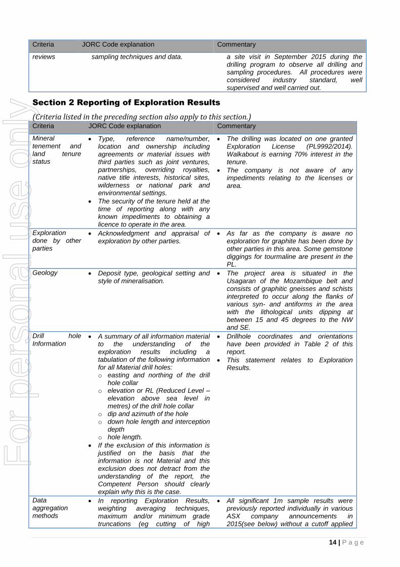
Section 2 Reporting of Exploration Results
(Criteria listed in the preceding section also apply to this section.) Criteria JORC Code explanation Commentary
Mineral tenement and land tenure status
Type, reference name/number, location and ownership including agreements or material issues with third parties such as joint ventures, partnerships, overriding royalties, native title interests, historical sites, wilderness or national park and environmental settings.
The security of the tenure held at the time of reporting along with any known impediments to obtaining a licence to operate in the area.
The drilling was located on one granted Exploration License (PL9992/2014). Walkabout is earning 70% interest in the tenure.
The company is not aware of any impediments relating to the licenses or area.
Exploration done by other parties
Acknowledgment and appraisal of exploration by other parties.
As far as the company is aware no exploration for graphite has been done by other parties in this area. Some gemstone diggings for tourmaline are present in the PL.
Geology Deposit type, geological setting and style of mineralisation.
The project area is situated in the Usagaran of the Mozambique belt and consists of graphitic gneisses and schists interpreted to occur along the flanks of various syn- and antiforms in the area with the lithological units dipping at between 15 and 45 degrees to the NW and SE.
Drill hole Information
A summary of all information material to the understanding of the exploration results including a tabulation of the following information for all Material drill holes: o easting and northing of the drill
hole collar o elevation or RL (Reduced Level –
elevation above sea level in metres) of the drill hole collar
o dip and azimuth of the hole o down hole length and interception
depth o hole length.
If the exclusion of this information is justified on the basis that the information is not Material and this exclusion does not detract from the understanding of the report, the Competent Person should clearly explain why this is the case.
Drillhole coordinates and orientations have been provided in Table 2 of this report.
This statement relates to Exploration Results.
Data aggregation methods
In reporting Exploration Results, weighting averaging techniques, maximum and/or minimum grade truncations (eg cutting of high
All significant 1m sample results were previously reported individually in various ASX company announcements in 2015(see below) without a cutoff applied
For
per
sona
l use
onl
y

15 | P a g e
Criteria JORC Code explanation Commentary
grades) and cut-off grades are usually Material and should be stated.
Where aggregate intercepts incorporate short lengths of high grade results and longer lengths of low grade results, the procedure used for such aggregation should be stated and some typical examples of such aggregations should be shown in detail.
The assumptions used for any reporting of metal equivalent values should be clearly stated.
where sampling has been conducted.
Aggregate graphite intersections are quoted using a cutoff of 5% TG and were averaged as all sample intervals are equal.
No metal equivalent values have been reported.
Relationship between mineralisation widths and intercept lengths
These relationships are particularly important in the reporting of Exploration Results.
If the geometry of the mineralisation with respect to the drill hole angle is known, its nature should be reported.
If it is not known and only the down hole lengths are reported, there should be a clear statement to this effect (eg ‘down hole length, true width not known’).
The drilling is at right angles to the mapped strike of the outcropping lithologies.
All intercepts are reported as down-hole lengths and are aimed at being as perpendicular to mineralisation as practical.
Diagrams Appropriate maps and sections (with scales) and tabulations of intercepts should be included for any significant discovery being reported These should include, but not be limited to a plan view of drill hole collar locations and appropriate sectional views.
A drillhole plan is provided in Figures 1 and 2.
Balanced reporting
Where comprehensive reporting of all Exploration Results is not practicable, representative reporting of both low and high grades and/or widths should be practiced to avoid misleading reporting of Exploration Results.
All 1m sample results were reported individually in various company ASX reports between November and December in 2015 (see below).
Other substantive exploration data
Other exploration data, if meaningful and material, should be reported including (but not limited to): geological observations; geophysical survey results; geochemical survey results; bulk samples – size and method of treatment; metallurgical test results; bulk density, groundwater, geotechnical and rock characteristics; potential deleterious or contaminating substances.
Previous announcements include:
RC Drilling results from this program (ASX: 1 December 2015; 24 November; 16 November 2015; & 4 November 2015), the release of assay data related to surface “dig and grab” samples (ASX: 14 May 2015) and also to the results of an Airborne VTEM Survey (ASX: 19 September 2015).
Graphite characterisation Petrography results (ASX: 30 July 2015), initial metallurgy (ASX: 3 June 2015) and recent DD core metallurgy (ASX: 8 January 2016).
Further work The nature and scale of planned further work (eg tests for lateral extensions or depth extensions or
Exploration drilling is complete at this time and a maiden graphite resource completed.
For
per
sona
l use
onl
y

16 | P a g e
Criteria JORC Code explanation Commentary
large-scale step-out drilling).
Diagrams clearly highlighting the areas of possible extensions, including the main geological interpretations and future drilling areas, provided this information is not commercially sensitive.
Future drilling will be planned to increase resource confidence where required and to also test additional targets generated through the VTEM survey and surface mapping.
Section 3 Estimation and Reporting of Mineral Resources
(Criteria listed in section 1, and where relevant in section 2, also apply to this section.) Criteria JORC Code explanation Commentary
Database integrity
Measures taken to ensure that data has not been corrupted by, for example, transcription or keying errors, between its initial collection and its use for Mineral Resource estimation purposes.
Data validation procedures used
The database was compiled by WKT using Microsoft Office software.
The database was supplied for use for resource estimation as a Microsoft Access database.
The database was linked to Geovia Surpac™ (industry standard resource modelling and estimation software). No errors were identified in the database supplied in visual checks and through the Surpac connect processes.
Normal data validation checks were completed on import to the Access database.
All logs were supplied as Excel spreadsheets and any discrepancies checked and corrected by field personnel. Data has been checked back to hard copy results.
Site visits Comment on any site visits undertaken by the Competent Person and the outcome of those visits.
Andrew Cunningham (appointed 13 November 2015 Director Walkabout Resources Ltd, and Competent Person) initially visited the site in July 2015 followed by a further visit in September 2015 whilst an independent geological consultant.
All drilling and sampling procedures were considered industry standard, well supervised and well carried out.
Geological interpretation
Confidence in (or conversely, the uncertainty of) the geological interpretation of the mineral deposit.
Nature of the data used and of any assumptions made.
The effect, if any, of alternative interpretations on Mineral Resource estimation.
The use of geology in guiding and controlling Mineral Resource estimation.
The factors affecting continuity both of grade and geology.
The confidence in the geological interpretation is considered robust for the purposes of reporting an Inferred Resource. Graphite is hosted within graphitic schists and gneisses of the Neoproterozoic Mozambique Belt. These graphite rich zones dip to the north-west and south-east at 15-45° and are interpreted to occur on the flanks of various syn- and antiforms in the area.
The geological interpretation is supported by geological mapping and drill hole logging and mineralogical studies completed on Walkabout’s recent drillholes plus geophysical survey data (VTEM).
A weathered zone (oxide and transition)
For
per
sona
l use
onl
y

17 | P a g e
Criteria JORC Code explanation Commentary
of reasonably uniform depth (averaging 9m) was interpreted based on the geological logs and coded into the block model.
No alternative interpretations have been considered at this stage.
Logged graphite rich zones in the graphitic schists correlate extremely well with TGC assay grades.
The key factors affecting continuity (known to date) are the presence of graphitic schist host rocks plus VTEM conductors.
Dimensions The extent and variability of the Mineral Resource expressed as length (along strike or otherwise), plan width, and depth below surface to the upper and lower limits of the Mineral Resource.
The modelled mineralised zone has dimensions of 1,000m (surface trace striking 030) with three main mineralised zones (one with a high-grade core) ranging in thickness up to 17m (Domain 1 including high grade core), 8m (Domain 3) and 30m (Domain 4 – eastern lower grade zone) ranging between 60m and 200m RL (AMSL).
Estimation and modelling techniques
The nature and appropriateness of the estimation technique(s) applied and key assumptions, including treatment of extreme grade values, domaining, interpolation parameters and maximum distance of extrapolation from data points. If a computer assisted estimation method was chosen include a description of computer software and parameters used.
The availability of check estimates, previous estimates and/or mine production records and whether the Mineral Resource estimate takes appropriate account of such data.
The assumptions made regarding recovery of by-products.
Estimation of deleterious elements or other non-grade variables of economic significance (eg sulphur for acid mine drainage characterisation).
In the case of block model interpolation, the block size in relation to the average sample spacing and the search employed.
Any assumptions behind modelling of selective mining units.
Any assumptions about correlation
Grade estimation using Ordinary Kriging (OK) was completed using Geovia Surpac™ software for TGC (%), Total Carbon (C %) and Vanadium (ppm) where vanadium is a potential by-product (Note: metallurgical testwork is required to support this assumption).
Drill spacing typically ranges from 100m to 160m.
Drillhole samples were flagged with wireframed domain codes. Sample data was composited for TGC, C and V to 1m using a best fit method with a minimum of 50% of the required interval to make a composite.
Influences of extreme sample distribution outliers were reduced by top-cutting on a domain basis. Top-cuts were decided by using a combination of methods including grade histograms, log probability plots and statistical tools. Based on this statistical analysis of the data population, top-cuts of between 26% and 32.5% TGC and 22% and 34% C were applied to two of the four domains. Top-cuts for TGC and C were not required for the other two domains. Only one domain required a top-cut of 2600ppm V.
Directional variograms were modelled by domain using traditional variograms. Nugget values for TGC are moderate (between 30 and 50%) for the lower grade domains and structure ranges up to 250m. The high grade core domain had a low nugget(12%) and structure range up to 175m. The V was modelled
For
per
sona
l use
onl
y

18 | P a g e
Criteria JORC Code explanation Commentary
between variables.
Description of how the geological interpretation was used to control the resource estimates.
Discussion of basis for using or not using grade cutting or capping.
The process of validation, the checking process used, the comparison of model data to drill hole data, and use of reconciliation data if available.
in 3 domains (there was no significant increase in the V in the high grade TGC zone) with low to moderate nugget values (between 15 and 35%) and structure ranges up to 280m.
Block model was constructed with parent blocks of 10m (E) by 25m (N) by 10m (RL) and sub-blocked to 5m (E) by 12.5m (N) by 5m (RL). All estimation was completed to the parent cell size. Discretisation was set to 5 by 5 by 2 for all domains.
Three estimation passes were used. The first pass had a limit of 150m, the second pass 300m and the third pass searching a large distance to fill the blocks within the wireframed zones. Each pass used a maximum of 12 samples, a minimum of 6 samples and maximum per hole of 4 samples.
Search ellipse sizes were based primarily on a combination of the variography and the trends of the wireframed mineralised zones. Hard boundaries were applied between all estimation domains.
Validation of the block model included a volumetric comparison of the resource wireframes to the block model volumes. Validation of the grade estimate included comparison of block model grades to the declustered input composite grades plus swath plot comparison by easting, northing and elevation. Visual comparisons of input composite grades vs. block model grades were also completed.
For reporting, V (ppm) is converted to Vanadium Oxide (V2O5) using the factor 1.78524 and then reported in %.
No previous resource estimations exist for this deposit.
Moisture Whether the tonnages are estimated on a dry basis or with natural moisture, and the method of determination of the moisture content
Tonnes have been estimated on a dry basis.
Cut-off parameters
The basis of the adopted cut-off grade(s) or quality parameters applied.
Grade envelopes have been wireframed to an approximate 5% TGC cut-off for Domains 1 to 3 allowing for continuity of the higher-grade zone. The lower grade Domain 4 is wireframed to an approximate 3-4% TGC cut-off. Based on visual and statistical analysis of the drilling results and geological logging of the graphite rich zones, this cut-off tends to be a natural geological change and coincides with the contact between the graphite rich schists and the other host rocks (i.e. biotite schists and gneisses, garnet gneisses and occasional
For
per
sona
l use
onl
y

19 | P a g e
Criteria JORC Code explanation Commentary
dolomites).
The material from within the modelled oxide/transition zone has been included in the reported Inferred Resource for now until. It is noted there is a risk that future metallurgical testwork may deem this material unusable.
Mining factors or assumptions
Assumptions made regarding possible mining methods, minimum mining dimensions and internal (or, if applicable, external) mining dilution. It is always necessary as part of the process of determining reasonable prospects for eventual economic extraction to consider potential mining methods, but the assumptions made regarding mining methods and parameters when estimating Mineral Resources may not always be rigorous. Where this is the case, this should be reported with an explanation of the basis of the mining assumptions made.
Based on the orientations, thicknesses and depths to which the graphitic rich zones have been modelled, plus their estimated grades for TGC and V, the potential mining method is considered to be open pit mining.
Metallurgical factors or assumptions
The basis for assumptions or predictions regarding metallurgical amenability. It is always necessary as part of the process of determining reasonable prospects for eventual economic extraction to consider potential metallurgical methods, but the assumptions regarding metallurgical treatment processes and parameters made when reporting Mineral Resources may not always be rigorous. Where this is the case, this should be reported with an explanation of the basis of the metallurgical assumptions made.
Perth based NAGROM Metallurgical plus specialist metallurgical consultants, Battery Limits Pty Ltd have both completed scoping metallurgical testwork and have recovered graphite flake of marketable qualities. (see ASX release “Excellent initial metallurgical test results for Lindi Jumbo” announced 8
th January
2016).
Environmental factors or assumptions
Assumptions made regarding possible waste and process residue disposal options. It is always necessary as part of the process of determining reasonable prospects for eventual economic extraction to consider the potential environmental impacts of the mining and processing operation. While at this stage the determination of potential environmental impacts, particularly for a greenfields project, may not always be well advanced, the status of early consideration of these potential environmental impacts should be reported. Where these aspects have not been considered this should be reported with an explanation of the environmental
Appropriate environmental studies and sterilisation drilling would be completed prior to determination of the location of any potential waste rock dump (WRD) facility.
For
per
sona
l use
onl
y

20 | P a g e
Criteria JORC Code explanation Commentary
assumptions made.
Bulk density Whether assumed or determined. If assumed, the basis for the assumptions. If determined, the method used, whether wet or dry, the frequency of the measurements, the nature, size and representativeness of the samples.
The bulk density for bulk material must have been measured by methods that adequately account for void spaces (vugs, porosity, etc), moisture and differences between rock and alteration zones within the deposit.
Discuss assumptions for bulk density estimates used in the evaluation process of the different materials.
Walkabout Resources completed specific gravity testwork on 175 drill core samples across the deposit using Hydrostatic Weighing (spray seal coated).
Of these 175 samples, 93 are from within the modelled mineralised domains.
Statistical analysis of the samples and comparison against depth and TGC grade identified a clear relationship between bulk density (BD) and TGC grade for Domain 1 (plus the high grade core domain). As such, the BD within these two domains was calculated by the equation: BD = (-0.0104 x TGC%) + 2.8292.
For Domain 3, the relationship was not so clear so the average BD for the zone of 2.5 g/cm3 was used.
Domain 4 was not intersected by any of the diamond core holes, so the average of 2.5 g/cm3 was applied.
For the modelled oxide/transition zone, a reduced BD of 2.0 g/cm3 was used.
Classification The basis for the classification of the Mineral Resources into varying confidence categories.
Whether appropriate account has been taken of all relevant factors (ie relative confidence in tonnage/grade estimations, reliability of input data, confidence in continuity of geology and metal values, quality, quantity and distribution of the data).
Whether the result appropriately reflects the Competent Person’s view of the deposit.
The Mineral Resource has been classified on the basis of confidence in the geological model, continuity of mineralised zones, drilling density, confidence in the underlying database and the available bulk density information.
All factors considered; the resource estimate has in part been assigned to Inferred Resources.
Audits or reviews
The results of any audits or reviews of Mineral Resource estimates.
Whilst Mr. Barnes (Competent Person) is considered Independent of Walkabout Resources, no third party review has been conducted.
Discussion of relative accuracy/confidence
Where appropriate a statement of the relative accuracy and confidence level in the Mineral Resource estimate using an approach or procedure deemed appropriate by the Competent Person. For example, the application of statistical or geostatistical procedures to quantify the relative accuracy of the resource within stated confidence limits, or, if such an approach is not deemed appropriate, a qualitative discussion of the factors that could affect the relative accuracy and confidence of
The relative accuracy of the Mineral Resource estimate is reflected in the reporting of the Mineral Resource as per the guidelines of the 2012 JORC Code.
The statement relates to global estimates of tonnes and grade. F
or p
erso
nal u
se o
nly

21 | P a g e
Criteria JORC Code explanation Commentary
the estimate.
The statement should specify whether it relates to global or local estimates, and, if local, state the relevant tonnages, which should be relevant to technical and economic evaluation. Documentation should include assumptions made and the procedures used.
These statements of relative accuracy and confidence of the estimate should be compared with production data, where available.
For
per
sona
l use
onl
y