SPECIFICATIONS PERFORMANCE - N16422
35
ARROW II SPECIFICATIONS PERFORMANCE Performance figures are for airplanes equipped for cross-country transportation and flown at oss weight under standard conditions at sea level or stated altitude. Any changes in equipment may result in changes in performance. Take-off Run (maximum effort, 25 ° flap) (ft) 770 Take-off Over 50-ft Barrier (maximum effort, 25 ° flap) (ft) 1600 Best Rate of Climb Speed (gear retracted) (mph) 100 Rate of Climb (ft per min) 900 Service Ceiling (ft) 15,000 Absolute Ceiling (ft) 17,000 Top Speed (mph) 175 Optimum Cruising Speed (75% power, optimum altitude) (mph) 165 Cruising Range (75% power, optimum altitude) (mi) 780 Optimum Cruising Range (55% power, optimum altitude) (mi) 900 Stalling Speed (flaps down, gear down) (mph) 64 Stalling Speed (flaps and gear up) (mph) 71 Landing Roll (flaps down) (ft) 780 * Landing Roll Over 50-ft Barrier (ft) 1380 * *This value applies only for the conditions indicated on the landing distance versus density altitude chart. WEIGHTS Gross Weight (lbs) Empty Weight (Standard) (lbs) USEFUL LOAD (Standard) (lbs) . *These weights are approximate. POWER PLANT Enne (Lycoming) Propeller (Hartzell) Rated Horsepower Rates Speed (rpm) Bore (in.) Stroke (in.) Displacement (cu in.) Compression Ratio Dry Weight (lbs) GENERAL SPECIFICATIONS \SSED: November \S, \97\ SED: lune 15, 1972 2650 1499* 1151* 10-360-ClC HC-C2YK-1( )/7666A-2 or HC-C2YK-1( )F/F7666A-2 200 2700 5.125 4.375 361.0 8.7:1 326 -1 [152kt] [143kt] [56kt] [62kt] [677NM] [782NM] MINIMAL N16422 POH
Transcript of SPECIFICATIONS PERFORMANCE - N16422

ARROW II
SPECIFICATIONS
PERFORMANCE
Performance figures are for airplanes equipped for cross-country transportation and flown at gross weight under standard conditions at sea level or stated altitude. Any changes in equipment may result in changes in performance.
Take-off Run (maximum effort, 25 °
flap) (ft) 770 Take-off Over 50-ft Barrier (maximum effort, 25
°
flap) (ft) 1600 Best Rate of Climb Speed (gear retracted) (mph) 100 Rate of Climb (ft per min) 900 Service Ceiling (ft) 15,000 Absolute Ceiling (ft) 17,000 Top Speed (mph) 175 Optimum Cruising Speed (75% power, optimum altitude) (mph) 165 Cruising Range (75% power, optimum altitude) (mi) 780 Optimum Cruising Range (55% power, optimum altitude) (mi) 900 Stalling Speed (flaps down, gear down) (mph) 64 Stalling Speed (flaps and gear up) (mph) 71 Landing Roll (flaps down) (ft) 780 *
Landing Roll Over 50-ft Barrier (ft) 1380 * *This value applies only for the conditions indicated on the landing distance versus density altitude chart.
WEIGHTS
Gross Weight (lbs) Empty Weight (Standard) (lbs) USEFUL LOAD (Standard) (lbs)
. *These weights are approximate.
POWER PLANT
Engine (Lycoming) Propeller (Hartzell)
Rated Horsepower Rates Speed (rpm) Bore (in.) Stroke (in.) Displacement (cu in.) Compression Ratio Dry Weight (lbs)
GENERAL SPECIFICATIONS \SS\JED: November \S, \97\
REVISED: lune 15, 1972
2650 1499* 1151 *
10-360-Cl CHC-C2YK-1( )/7666A-2
or HC-C2YK-1 ( )F /F7666A-2 200
2700 5.125 4.375 361.0 8.7:1
326
1'-1
[152kt]
[143kt]
[56kt]
[62kt]
[677NM]
[782NM]
MINIMAL N16422 POH
j07rdi
Highlight
j07rdi
Highlight
j07rdi
Highlight

ARROW.II
FUEL AND OIL
Usable Fuel Capacity (U. S. gal) Oil Capacity (qts) Fuel, Aviation Grade (min octane)
BAGGAGE
Maximum Baggage (lbs) Baggage Space (cu ft) Baggage Door Size (in)
DIMENSIONS
Wing Span (ft) Wing Area (sq ft) Wing Loading (lbs per sq ft) Length (ft) Height (ft) Power Loading (lbs per hp)
LANDING GEAR
Wheel Base (ft) Wheel Tread (ft) Tire Pressure (psi) Nose
Main Tire Size Nose (four-ply rating)
Main (four-ply rating)
48 8
100/130
200 22
20 X 22
32.2 170 15.6 24.6
8.0 13.25
7.8 10.5
30 27
5.00 X 5 6.00 X 6
GENERAL SPECIFICATIONS
ISSUED: November 15, 1971
MINIMAL N16422 POH
j07rdi
Highlight
j07rdi
Highlight
j07rdi
Highlight
j07rdi
Highlight

SECTION I
LIMIT A TIO NS
ARROW
The following limitations must be observed in the operation of this airplane:
A. ENGINELycoming IO-360-Cl C
ENGINE LIMITSFor all operations 2700 RPM, 200 HP
B. FUEL100/130 Octane Aviation Gasoline (Minimum)
C. PROPELLERHartzell HC-C2YK-1( )/7666A-2 or Hartzell HC-C2YK-1( )F/F7666A-2
Pitch Settings at 30 in. Station:High 29.0
°
± 2°
, Low 14°
± .2°
Diameter: Maximum 74 inches Minimum 72.5 inches (Avoid continuous operation 2100- 2350 RPM)
D. INSTRUMENT MARKINGS (Power Plant)
OIL TEMPERATUREGreen Arc (Normal Operating Range) Red Line (Maximum)
OIL PRESSURE Green Arc (Normal Operating Range) Yellow Arc (Caution Range) Red Line (Minimum) Red Line (Maximum)
FUEL PRESSURE Green Arc (Normal Operating Range) Red Line (Minimum) Red Line (Maximum)
TACHOMETER Green Arc (Normal Operating Range) Red Arc Red Line (Maximum Continous Power)
FAA APPROVED October 14, 1971
REVISED: December 5, 1975
75°
F to 245°
F 245
°
F
60 PSI to 90 PSI 25 PSI to 60 PSI
25 PSI if installed or 60 PSI if installed 90 PSI
14 PSI to 45 PSI 14 PSI 45 PSI
500 to 2100 and 2350 to 2700 RPM 2100 to 2350 RPM
2700 RPM
REPORT: VB-343 PAG 34 MODEL: P A-28R- 00
MINIMAL N16422 POH
j07rdi
Highlight
j07rdi
Highlight
j07rdi
Highlight
j07rdi
Highlight
j07rdi
Highlight
ARROW
E.
F.
G.
H.
I.
AIRSPEED LIMITATIONS AND INSTRUMENT MARKINGS (Calibrated Airspeed)
NEVER EXCEED SPEED 214 MPH MAXIMUM STRUCTURAL CRUISE SPEED 170 MPH MANEUVERING SPEED 131 MPH FLAPS EXTENDED SPEED 125 MPH MAXIMUM GEAR EXTENSION SPEED 150 MPH MAXIMUM GEAR RETRACTION SPEED 125 MPH
AIRSPEED INSTRUMENT MARKINGS Red Radial Line (Never Exceed) 214 MPH (186 KT) Yellow Arc (Caution Range) 170 MPH to 214 MPH
(Smooth Air Only) (148 KT to 186 KT) Green Arc (Normal Operating Range) 71 MPH to 170 MPH
(62 KT to 148 KT) White Arc (Flap Down Range) 64 MPH to 125 MPH
(56 KT to 109 KT)
FLIGHT LOAD FACTORS Positive Load Factor (Maximum) 3.8 G Negative Load Factor (Maximum) No inverted maneuvers approved
MAXIMUM WEIGHT 2650 LBS
BAGGAGE CAPACITY 200 LBS
C. G. RANGE
Weight Forward Limit Rearward Limit Pounds Inches Aft of Datum Inches After of Datum
-
2650 87.3 93.0 2300 82.0 93.0 1800 80.0 93.0
NOTES
l. Straight line variation between points given.2. The datum used is 78.4 inches ahead of the wing leading
edge at the intersection of the straight and tapered section.3. It is the responsibility of the airplane owner and the pilot to
insure that the airplane is properly loaded. See "Weight andBalance Section" for proper loading instructions.
PORT: VB-343 PAGE 3-2 DEL: PA-28R-200
FAA APPROVED October 14, 1971
REVISED: January 21, 1972
-
.,..
(186 KT)
(148 KT)
(114 KT)
(109 KT)
(130 KT)
(109 KT)
I
MINIMAL N16422 POH
j07rdi
Highlight
j07rdi
Highlight
j07rdi
Highlight
j07rdi
Highlight
j07rdi
Highlight
j07rdi
Highlight

-
J.
K.
MANEUVERS All acrobatic maneuvers including spins prohibited.
PLACARDS In full view of the pilot:
"THIS AIRCRAFT APPROVED FOR NIGHT IFR NON-I -::ING FLIGHT WHEN EQUIPPED IN ACCORDANCE WITH FAR 91 OR FAR 135."
"THIS AIRCRAFT MUST BE OPERATED AS A NORMAL CATEGORY AIRPLANE IN COMPLIANCE WITH THE OPERATING LIMITATIONS STATED IN THE FORM OF PLACARDS, MARKINGS AND MANUALS."
ARROW
In full view of the pilot, the following takeoff and landing check lists will be installed:
Fuel on Proper Tank Electric Fuel Pump - On Engine Gauges - Checked Alternate Air - Closed Seat Backs Erect
Fuel on Proper Tank Seat Back Erect Fasten Belts/Harness
TAKEOFF CHECK LIST Mixture - Set Propeller - Set Fasten Belts/Harness
LANDING CHECK LIST Electric Fuel Pump - On Mixture - Rich Propeller - Set
Flaps - Set Trim Tab - Set Controls - Free Door - Latched Air Conditioner - Off
Gear Down (l 50 MPH Max) Flaps - Set ( 125 MPH) Air Conditioner - Off
The "AIR CONDITIONER OFF" item in the above takeoff and landing check lists is
mandatory for air conditioned aircraft only.
In full view of the pilot:
�-�
. ,,
"NO ACROBATIC MANEUVERS IN�·L{lDING SPINS APPROVED."
"MANEUVERING SPEED. -J.3J MPH."------··-'.--:-:.·-- -· -· ,_ ... --- - -· --- .... -.. ---· ·- .- -· .. . .
On the instrument panel in full view of th� pilot:
"DEMONSTRATED CROSSWIND COMP.ONENT- 20 MPH."• 1 • • • • • ' . •
FAA AntlOVEDOctober 14, 1971 UYISED: F�wy 18, 19'71
(130 KT)(109 KT)
(114 KT)
(18 KT)
MINIMAL N16422 POH
j07rdi
Highlight
j07rdi
Highlight
j07rdi
Highlight
j07rdi
Highlight

ARROW
Adjacent to upper door latch:
"ENGAGE LATCH BEFORE FLIGHT'
On the inside of the baggage compartment door:
"BAGGAGE MAXIMUM 200 LBS. SEE WEIGHT AND BALANCE DATA FOR BAGGAGE LAODINGS BETWEEN 150 LBS AND 200 LBS."
Near emergency gear lever:
"EMERGENCY DOWN"
Near emergency gear lever (aircraft equipped with backup gear extender):
"OVERRIDE ENGAGED AUTO-EXT-OFF LOCK PIN ON SIDE
TO ENGAGE OVERRIDE: PULL LEVER FULL UP, PUSH LOCK PIN
TO RELEASE OVERRIDE: PULL LEVER FULL UP & RELEASE''
Near landing gear selector switch:
"GEAR UP "DOWN
125 MPH MAX" 150 MPH MAX"
In full view of the pilot when AutoFlite is installed:
"FOR HEADING CHANGES: PRESS DISENGAGE SWITCH ON CONTROL WHEEL. CHANGE HEADING, RELEASE DISENGAGE SWITCH."
On the instrument panel in full view of the pilot when the oil cooler winterization kit is installed:
"O IL;� t'i�li�1t ·:�ii'�}]!JiA�O.�::i�l{J;�'.;:f;, BEREMOiYEPr-W��N AM&lENI�JfE!MPE�TlfR.EJEtXeEJEDS soo
. ...; · ••1j..• ;.;- ·•,.:• !.,J' .. t,1- i �1.i..�;'--:(1 1,'J;�kc a,"':�::7!f.'... Ori°'the· instrument -panel mi !fUA\cY�,,9Ji�be.:pil-ot twhen: ·tho :supplementary white strobe
lights are installed: :, .r..t. ·.,. J ::..�/-:�,: • ;. __ .
t.,:-:i,: J '.. · ; .. "WARNING ·--:-i'":'f.t!JRN '-1
0FFrfr"Sl!ROBE:·:·_uGHiS!; WHEN TAXIING IN. VICINITY OF OTHER''•�{R.CRATT;' ·OR
�- DU�JN,9_.f:1:1y�T. Tl;f�P-Hfl�fbP�-H?i f.pgr flR �AZ�.";
.. " F'AA APPROVED October 1
14,. 1'97f REVISEB��Jahuary· 3i,'i9&',
(109 KT)
(130 KT)
RE.P<()rtfr.-BV:;rJ43-{!AG£ 3-4 . · ~D.EL: ,.P-A~ll'R .:i.ao
MINIMAL N16422 POH
j07rdi
Highlight
j07rdi
Highlight
j07rdi
Highlight
j07rdi
Highlight
j07rdi
Highlight

EMERGENCY PROCEDURE
Introduction . . . . . . . . . . . . . . . . . . . . . . . . . . . . . . . . . . . . . . . . . . . . Engine Fire During Start .................................... . Engine Power Loss During Take-Off . . . . . . . . . . . . . . . . . . . . . . . . . . . . . . . Engine Power Loss In Flight .................................. . Power Off Landing . . . . . . . . . . . . . . . . . . . . . . . . . . . . . . . . . . . . . . . . .
I Gear Down Landing . . . . . . . . . . . . . . . . . . . . . . . . . . . . . . . . . . . . . . . .·Gear Up Landing ......................................... .Propeller Overspeed . . . . . . . . . . . . . . . . . . . . . . . . . . . . . . . . . . . . . . . . Emergency Landing Gear Extension .............................. . Spins . . . . . . . . . . . . . . . . . . . . . . . . . . . . . . . . . . . . . . . . . . . . . . . . .
Open Door ............................................ . Fire . . . . .. . . . . .. . . . . . · · · · · · · · · · · · · · · · · · · · · · · · · · · · · · · ·
Loss of Oil Pressure . . . . . . . . . . . . . . . . . . . . . . . . . . . . . . . . . . . . . . . . Loss of Fuel Pressure ...................................... . High Oil Temperature . . . . . . . . . . . . . . . . . . . . . . . . . . . . . . . . . . . . . . . Alternator Failure . . . . . . . . . . . . . . . . . . . . . . . . . . . . . . . . . . . . . . . . .
-
4-14-14-24-34-34-44-5
4-5
4-5
4-64-64-74-74-84-84-8
MINIMAL N16422 POH
j07rdi
Highlight

ARROW II
ENGINE POWER LOSS DURING TAKE-OFF
The proper action to be taken if loss of power occurs during take-off will depend on circumstances.
4-2
1. If sufficient runway remains for a normal landing, leave the gear down and landstraight ahead.
2. If the area ahead is rough, or if it is necessary to clear obstructions, put gear selectorswitch in the "UP" position, and latch the gear lever in the override position.
3. If you have gained sufficient altitude to attempt a restart, proceed as fo11ows:a. MAINTAIN SAFE AIRSPEEDb. FUEL SELECTOR - SWITCH TO ANOTHER TANK CONTAINING FUELc. ELECTRIC FUEL PUMP - CHECK ONd. MIXTURE - CHECK RICHe. ALTERNATE AlR-ONf. EMERGENCY GEAR LEVER -AS REQUIRED
NOTE
The landing gear will extend automatically when engine power fails at speeds below approximately I 05 MPH IAS. Glide distance with the gear extended is roughly halved; if conditions dictate, the gear can be retained in the retracted position by latching the lever in the override up position.
NOTE
If engine failure was caused by fuel exhaustion, power will not be regained after tanks are switched until empty fuel lines are filled, which may require up to ten seconds.
If power is not regained, proceed with the POWER OFF LANDING procedure.
EMERGENCY PROCEDURES
ISSUED: November 1 S, 1971
MINIMAL N16422 POH
j07rdi
Highlight

ARROW 11
ENGINE POWER LOSS IN FLIGHT
Complete engine power loss is usually caused by fuel flow interruption, and power will be restored shortly after fuel flow is restored. If power loss occurs at low altitude, the first step is to prepare for an emergency landing (See POWER OFF LANDING). Maintain an airspeed of at least 110 MPH IAS, gear and flaps up and if altitude permits proceed as follows:
J. Fuel Selector - SwHch to another tank containing fuel.2. Electric Fuel Pump - On3. Mixture- Rich4. Alternate Air - On5. Engine Gauges - Check for indication of the cause of power Joss.6. If no fuel pressure is indicated, check tank selector position to be sure it is on a tank
containing fuel.
When power is restored: 7. Alternate Air - Off8. Electric Fuel Pump - Off
If the above steps do not restore power, prepare for an emergency landing. ff time permits: 1. Ignition Switch - "L" then "R" then back to "BOTH."2. Throttle and Mixture - Different settings. (This may restore power if problem is too
rich or too lean a mixture, or partial fuel system restriction.3. Try another fuel tank. (Water in the fuel could take some time to be used up, and
allowing the engine to windmill may restore power. If power loss is due to water, fuelpressure indications will be normal).
NOTE
If engine failure was caused by fuel exhaustion, power will not be restored after tanks are switched until empty fuel lines are filled, which may require up to ten seconds.
If power is not restored, proceed with POWER OFF LANDING procedures.
POWER OFF LANDING
If loss of power occurs at altitude, trim the aircraft for best gliding angle ( I 05 MPH IAS) (Air Cond. of
f
) and look for a suitable field. (See Note) If measures taken to restore power are not effective, and if time permits, check your charts for airports in the immediate vicinity; it may be possible to land at one if you have sufficient altitude. At best gliding angle, with the engine windmilling, and the propeller control in full "decrease RPM," the aircraft will travel approximately 1.6 miles for each thousand feet of altitude. If possible, notify the FAA by radio of your difficulty and intentions. If another pilot or passenger is aboard, let him help.
When you have located a suitable field, establish a spiral pattern around this field. Try to be at 1000 feet above the field at the downwind position, to make a normal landing approach. When the field can easily be reached, slow to 90 MPH IAS for the shortest landing.
EMERGENCY PROCEDURES ISSUED: November 15, 1971 REVISED: February 4, 1972
4-3
•
MINIMAL N16422 POH
j07rdi
Highlight
j07rdi
Highlight

ARROW II
CAUTION
This will increase your rate of descent, so be sure you have adequate altitude. Excess altitude may be lost by widening your pattern, using flaps or slipping, or a combination of these.
Whether to attempt a landing with gear up or down depends on many factors. If the field chosen is obviously smooth and firm, and long enough to bring the plane to a stop, the gear should be down. If there are stumps or rocks or other large obstacles in the field, the gear in the down position will better protect the occupants of the aircraft. If, however, the field is suspected to be excessively soft or short, or when landing in water of any depth, a wheels-up landing will nonnally be safer and do less damage to the airplane.
Don't forget that at airspeeds below approximately 105 MPH IAS the gear will free fall, and will take six to eight seconds to be down and locked. If a gear up landing is desired, it will be necessary to latch the override lever in the up position before airspeed drops to 1 15 mph to prevent landing gear from inadvertently free falling.
Touchdown should normally be made at the lowest possible airspeed.
GEAR DOWN LANDING
4-4
For a gear down landing, proceed as follows when committed to landing: 1 . Close throttle and shut off the master and ignition switches 2. Flaps as desired3. Turn the fuel selector valve to off4. Mixture - Idle cut-off5. Tighten seat belt (and shoulder harness, if available)6. Touchdown at lowest possible airspeed
NOTE
Automatic gear mechanism will extend the gear below approximately 105 MPH IAS with power off. Be prepared to latch the emergency override lever UP before airspeed drops to 115 mph to prevent landing gear from inadvertently free falling, unless gear extension is desired.
NOTE
ing gear cannot be retracted.
EMERGENCY PROCEDURES
ISSUED: November IS, 1971 REVISED: March 30, 1973
\.
,.,.. . .._
MINIMAL N16422 POH
j07rdi
Highlight

. )
·''
In the event a gear up lan<iing is required, proceed as follows when commTitii{
td1an(j.ing: 1. On aircraft ·equipped with 'the backup gear extender: Lock emergen�y i_e#' I_ i/r in
"Override Engaged.,, position. .. : .: • :., ;•. 2. Flaps as desired.3. Close throttle and shut off the master and ignition switches.4. Turn the fuel selector valve to off.5. Mixture -· Idle cut-off.6. Tighten seat belt (and shoulder harness, if available).7. Contact sufface at minimum possible airspeed.
NOTE
Witti the master switch off, the landing gear cannot be retracted .
. PROPELLER OVERSPEED ..
Propeller ove.rspeed is �µsed by a malfunction in the propeller gpverno� .. or lo� oil pressure, which allows the 'f)ropelfcr rliladei'to�fotafe to fufi1 f� pitc'h. If"fhis�noCtld.'3<:W: proceed as follows:
.,.,,. i � -J· ..\ • � �,, I"'(" ,._ 1 J • -
I. THROTTLE- RETARD •01 .• �.J • • « • ...tJ,.,..._ h.1:,.i' "'�-�-2. OIL PRESSURE - CHECK3 .. - PRO(:>E('l!ER"·C0NTR'OV.-- PULL-DEGR-EASE.· RPM,· :r-REN"'SET IF ANY
CONTROL- AVAILABLE ' .. H •--:. � ;. • • ., 4. ·,.'tEDUCE .AIRSPEED 'l ; .•. ! ··::': �. • •i;- 1· l:
5. i;HROITLE � AS REQUIRED TO REMAIN BELOW i-700 ,R"P.M-'_ . �I - ._. "' •
EMERGENCY LANDING GEAR EXTENSION .
ll • ._,
• I •
• ,. •• � • + ..
Accomplish the following checks prior to initiation of the emergency e'xtension procedure: l . Master Switch - Check On 2. Circuit Breakers - Check • , ·3. Panel Lights - Off (in daytime) - � -·, • ; -: ; ·,•t)'.l:-:. ''.4. Gear Indicator Bulbs - Check
� --J.' ,,� .......
If landing gear does not check down and locked: S. - Raa��airs�cf below;fOO�h -�>r: • �,:•..: i· b��':':JP"". •;u :_, i.1': ·-n: '. 6. ��� .. faiicllnj�:se.feefor 1s,yifch"to�ear cl"t)Mi•l)b�i't,ickf'_tU:t-J•��!. 7. -If geir"!14.ifa' "_�lockrdo'Ytl• oh7airc'raft ·equ'fp·��fflf;_tfie tiackup gear extender.
raise�rjeb"t,fiear;ifev.dfto '.t60ve'rffile'Ertgisgecf' r;osition �: �-·. �,8. ·If-·ie)i(.'�� sUU·' Fa'ile�- _:.ftP/loc� tiown(lmoVe 'emeigency ·geai-7iJever to "Emergency
Down .. position9. If gear has still failed to lock:''db°wn(yaw the airplane.abruptly from side to side-with
the rudder.. ; .
NOTE
If all electrical. power has. been lost, the landing gear must be extended using the above emergency procedures. The landing gear position indicillor lights will not be operative .
.. . � ' ,1 • �
I EMERGENCY P�QfEDU.RESREVISED::Januarj 31r·tffl
Ait1H,w 11
...
,,.
r •
..
MINIMAL N16422 POH
j07rdi
Highlight
j07rdi
Highlight
j07rdi
Highlight

ARROW II
: . - .. -
NOTE
Refer to page 3-1 I for differences when emergency extension procedure is performed for training purposes.
; SPl�S . ' . . ... ; -'•
1 • Intentional spins are prohibited in this aircraft. If a spin is inadvert.ently entered, immediatelyuse the following recovery procedures: '--
1. THROTTLE - IDLE2. RUDDER - FULL OPPOSITE TO DIRECTION OF ROTATION'3. CONTROL WHEEL - FULL FORWARD
. ·' 4. RUDDER - NEUTRAL (WHEN ROTATION STOPS)5. CONTROL WHEEL - AS REQUIRED TO SMOOTHLY REGAIN LEVEL FLIGHT
ATTITUDE "' .. . n
.. . .. ..
•('' '
t• ' •
{ ·j ' � ., ...• < N0t'E '· :- . .,. ,..,. :,;:
• • .. • . -.-1, , w, r.,:,.�.IJ !" .Ii 11-•1r I 'l'� l: •
On·.aircraft-eq�ipped ·with �he �kbp gear :ext:h.tl"el-tWflantfi�{l .. •I 'J '.,:l
gear will extend in ,this flight condition, but will .retract du�ing recovery, and has no adverse affect on the ·spin characteristics.
OPEN P�O�• 1� '3 1 t' .. •.:.
The ca,bin door on the Cherokee Arrow· II is latched at four points 'so the chances of its opening in ,fli�t arc remote. However, siioulcfyou forget to completely clo'� or latch the door. itmay open p�i;tially. This will usually happen soon after take-off. An open door will not affect thenormal fligbt_chuacteristics, and a normal landing can be made with it open. If the door opens it will trail in a slig�tly open position, and the airspeed will be reduced slightly.
C
• 11 •
\' t.j •r.,,, .:;,i, ... ,t�LJ -•ri••kJt r,�=\.:' 1,. ... � '••¥ • • • - , ·,rn � · .,·,ll'je1: , .. ,. ... i..r. .lo•·· • 1 • .,i,. ...... ,,::,� .,/t \,lf"t'.!·:.:..., u '- .. •i'";; . .. , ... ·� ... • • • I' -
• • 1J ... -· t.,.\ .. -.c· � - "', '-" , ... ,.. 1 r •.-=-' _.. ,. >.·· __ , -: ..• ,,,u;1, 1'' "',:1 ., ,,.,.,, .;,,,\,.�·1!'C· t "•-', .• ""Jt°,'·'i,�·�,.,/_ \,
. ( '
' .,
: i-' ....
.. ... .. , . .
,)
l "l. - ·. .. , .. ' ,
. ���\;t;�tt�tflfAL . . . ' ..
... ,j,1 • • • \..";
i'i ' I I
l : .... :~ ,'t • ~.,:,
.-:· ... :_
4-6
MINIMAL N16422 POH
j07rdi
Highlight
j07rdi
Highlight

ARROWD
FIRE
The presence of fire is noted through smoke, smell, and heat in the cabin. It is essential that the source of the fire be promptly identified through instrument readings, character of the smoke, or other indications, since the action to be taken differs somewhat in each case.
I . Source of Fire - Check a. Electrical Fire (Smoke in Cabin):
( 1 ) Master Switch - Off(2) Vents - Open(3) Cabin Heat - Off(4) Land as soon as practicable.
b. Engine Fire:(1) In case of engine fire in flight
(a) Fuel Selector - OFF(b) Throttle - CLOSE(c) Mixture - IDLE CUT OFF(d) Heater - Off (In all cases of fire)(e) Defroster - OFF (In all cases of fire)(f) If terrain permits - Land Immediately
The possibility of an engine fire in flight is extremely remote. The procedure given above is general and pilot judgement should be the deciding factor for action in such an emergency.
(2) In case of engine fire on the ground(a) If engine has not started
1. Mixture - IDLE CUT OFF2. Throttle - OPEN3. Tum engine with starter (This is an attempt to pull the fire into
the engine.)(b) If engine has already started and is running, continue operating to try
pulling the fire into the engine.(c) In either case stated in (a) and (b), if the fire continues longer than a
few seconds, the fire should be extinguished by the best availableexternal means.
(d) If external fire extinguishing is to be applied1. Fuel Selector Valves - OFF2. Mixture- IDLE CUT OFF
LOSS OF OIL PRESSURE
Loss of oil pressure may be either partial or complete. A partial loss of oil pressure usually indicates a malfunction in the oil pressure regulating system, and a landing should be made as soon as possible to investigate the cause and prevent engine damage.
A complete loss of oil pressure indication may signify oil exhaustion or may be the result of a faulty gauge. In either case, proceed toward the nearest airport, and be prepared for a forced landing. If the problem is not a pressure gauge malfunction, the engine may stop suddenly. Maintain altitude until such time as a dead stick landing can be accomplished. Don't
EMERGENCY PROCEDURES
ISSUED: November 1S, 1971 4-7
MINIMAL N16422 POH
j07rdi
Highlight
j07rdi
Highlight

ARROWD
change power settings unnecessarily, as this may hasten complete power loss.
Depending on the circumstances, it may be advisable to make an off airport landing while power is still available, particularly if other indications of actual oil pressure loss, such as sudden increase in temperatures, or oil smoke, are apparent, and an airport is not close.
If engine stoppage occurs, proceed to POWER OFF LANDING.
LOSS OF FUEL PRESSURE
I. Electric Boost Pump - On.2. Mixture Control Forward.3. Fuel Selector - Check on full tank.
If problem is not an empty fuel tank, land as soon as practicable and have the fuel system checked.
IDGH OIL TEMPERATURE
An abnonnally high oil temperature indication may be caused by a low oil level, an obstruction in the oil cooler, damaged or improper baffle seals, a defective gauge, or other causes. Land as soon as practicable at an appropriate airport, and have the cause investigated.
A steady, rapid rise in oil temperature is a sign of trouble. Land at the nearest airport and let a mechanic investigate the problem. Watch the oil pressure gauge for an accompanying loss of pressure.
ALTERNATOR FAILURE
Loss of alternator output is detected through a zero reading on the ammeter. Before executing the following procedure, insure that the reading is zero and not merely low by actuating an electrically powered device, such as the landing light. If no increase in the ammeter reading is noted, alternator failure can be assumed.
1. Reduce electrical load.2. Alternator Circuit Breakers - Check.3. ":Alt" Switch - Off (for 1 second), then On.
If the ammeter continues to indicate no output, or alternator will not stay reset, tum off "Alt" switch, maintain minimum electrical load, and land as soon as practical. All electrical power is being supplied by the battery.
4-8
NOTE
If the battery is fully discharged, the gear will have to be lowered using the "EMERGENCY LANDING GEAR EXTENSION" procedure, and the position lights will of course not be operating.
EMERGENCY PROCEDURES REVISED: December S, 1975
MINIMAL N16422 POH
j07rdi
Highlight
j07rdi
Highlight
j07rdi
Highlight

WEIGHT AND BALANCE FOR
CHEROKEE ARROW
MODEL PA-28R-2OO
ISSUED: August 2, 1972 REPORT: VB-334
MODEL: PA-28R-200
MINIMAL N16422 POH

-,
CUMBERLAND AVIONICS, LLC 210 TUNE AIRPORT DRIVE
NASHVILLE TN 37209
FAA REPAIR STATION X24R306X
A/C PA28R-200
5/N: 28R7335145
Call sign: N16422
Old empty wgt: 1603.7 Old empyt wgt cg: 82.65
Old useful load: 1046.3 Old moment: 132,550.02
\IRCRAFT WAS WEIGHED 10/15/14
Revised Weight & Balance
Page 1
Taken from W&B
Dated: 10/15/14
New empty wgt:
New empty wgt cg
New useful load
New moment:
1598.4
83.6
1051.6
133,626.24
MINIMAL N16422 POH
j07rdi
Highlight
j07rdi
Highlight

450
400
350
en 0 z 300 :, . 0
... 250 :c
� w3:0 200
0
150 J
II' , IJ .,
100 J ., I/
'/ , � ,
V
50 J / ,,, ,, r,,,,,
0 ;"': ,.
0 5 10
ISSUED: October 14, 1971
15
LOADING GRAPH
J
., I.I
',,I ,,
,.,
20
J J
, I
1,.'> fl,
�<S,, �-0�
�) '<'-0 ,I I-- �
b �<I
'b<:.' 1._--- j - fl,,_
.,
. "I. -- � �03/
<it --< � c,'>e
, I-... '<"' q'I>
'I.'- , �--'" .... .,
I/ I,;
I.I / J
., ',,I �e
�./(>r:i,C/,�
I,;'
11
I
25 30 35 40
ARROW
45 50
MOMENT/1000 (POUND - INCHES)
REPORT: VB-334 PAGE 5-9
MODEL: PA-28R-200
7 /I
& I . : , ' '
I .. l l ., I I .,. I I I .
I
I V J I
I I
V .,. ~- , -I.I -V
~ V
_J
I V
. I l •
V V
-._~L -' i.. '- it.-v...r
I I
1 I
·7
•
MINIMAL N16422 POH
ARROW
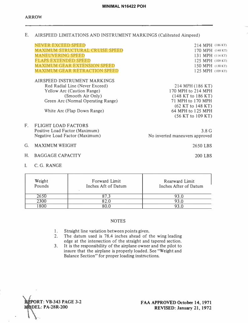
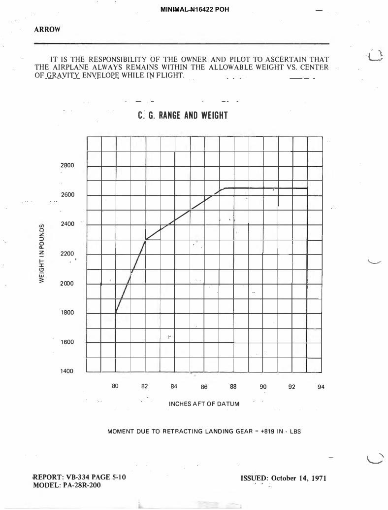
IT IS THE RESPONSIBILITY OF THE OWNER AND PILOT TO ASCERTAIN THAT
THE AIRPLANE ALWAYS REMAINS WITHIN THE ALLOWABLE WEIGHT VS. CENTER
OF GRAVITY ENVELOPE WHILE IN FLIGHT.
C. G. RANGE AND WEIGHT
2800
2600 �.,,
,
/ V
2400 •' / '
/
/ ,/
z 2200
,
2000 ,
1800
-1600
1400
80 82 84 86 88 90 92 94
INCHES AFT OF DATUM
M OMENT DUE TO RETRACTING LAND ING GEAR= +819 IN. LBS
REPORT: VB-334 PAGE 5-10
MODEL: P A-28R-200
ISSUED: October 14, 1971
(I)
0 z ::> ~
' I I
I I
'
'
j
I II
-
-
I
I
.
I
-
-
MINIMAL N16422 POH

ARROWll
OPERA TING INSTRUCTIONS
PREFLIGHT
The airplane should be given a thorough visual inspection prior to each flight. Particular attention should be given to the following items:
Master switch and ignition OFF; landing gear switch DOWN; remove seat belt securing control wheel or wheel control_lock.
1.
2.
3.
a. Check for external damage and operational interference of control surfaces orhinges.
b. Insure that wings and control surfaces are free of snow, ice or frost.a. Visually check fuel supply; secure caps.b. Drain all fuel system sumps and lines.c. Check that fuel system vents are open.d. Check landing gear shock struts for proper inflation (approximately 2 inches
showing).
. ......................................... . . � . . :
\ I
. .
. . : ................ ·•· ....... : : ...... ·• ................. :
......... .
..
. ♦
. . ..
�.
...........=·················•····················:
. . . .....
. .•• •
• . . . . ............................ .. . . . .
. .....················. ...... .
• ....... . .............. .
. . : ............... ·•· ..................... :
O\>ERA TING \NSTilUCTlONS ISSUED:November 15, 1971 REVISED: June 15, 1972
6-1
. . . •
MINIMAL N16422 POH

ARROW II
e.
f.
Check hydraulic lines and landing gear cylinders for leaks. Check tires for cuts, wear and proper inflation.
g.
4. a.
Check brake blocks and discs for wear and damage. Check windshield for cleanliness.
b.
C.
Check propeller and spinner for defects or nicks. Check for obvious fuel or oil leaks.
d.
e.f.
Check oil level. (Insure dipstick is properly seated.) Check cowling and inspection covers for security. Check cowl scoop for obstructions.
g. Check nose wheel tire for inflation or wear.h. Check nose gear shock strut for proper inflation (approximately 2-3/4 inches
showing).i. j.
Check hydraulic lines and landing gear cylinder for excessive leaks.Check for foreign matter in air inlet.
5. a.
b.
c.
Stow tow bar and control locks if used.Check baggage for proper storage and security.Close and secure the baggage compartment door.
6. a. Upon entering airplane check that all primary flight controls operate properly,and that aircraft is properly loaded.
b. Close and secure cabin door.c. Check that required papers are in order and in the airplane.
STARTING ENGINE
After completetion of the preflight inspection: 1. Set parking brakes ON.2. Set the propeller control in full INCREASE RPM (control forward).3. Select the desired tank with fuel selector valve.
STARTING ENGINE WHEN COLD
I. Open the throttle appr<_>ximately 1 /2 inch.2. Tum the master switch ON.3. Turn the electric fuel pump ON.4. Move the mixture control to FULL RICH until an indication on the fuel flow meter is
noted. (Engine is primed.)5. Move the mixture control to IDLE CUT-OFF.6. Engage the starter by rotating magneto switch clockwise and pressing in.7. When the engine fires, advance mixture control to FULL RICH and move throttle to
the desired setting.8. If the engine does not frre within five to ten seconds, disengage starter and reprirne.
STARTING ENGINE WHEN HOT
1. Open the throttle approximately I /2 inch.2. Turn the master switch ON.3. Tum the electric fuel pump ON.4. Put mixture control in IDLE CUT-OFF.5. Engage the starter by rotating magneto switch clockwise and pressing in. When the
engine fues, advance the mixture control and move the throttle to desired setting.
OPERATING .INSTRUCTIONS
6-2 ISSUED: November 15, 1971
.....
,
MINIMAL N16422 POH
j07rdi
Highlight
j07rdi
Highlight
� ', .....
• J
STARTING ENGINE WHEN FLOODED
1 . Open the throttle full. 2. Tum the master switch ON.3. Tum the electric fuel pump OFF.4. Put mixture control in IDLE CUT-OFF.
ARROW II
S. Engage the starter by rotating the magneto switch clockwise and pressing in. Whenthe engine fires, advance the mixture control and retard the throttle.
STARTING WITH EXTERNAL POWER
An optional feature known as Piper External Power (PEP) allows the operator to use an external battery to crank the engine without having to gain access to the aircraft battery.
The procedure is as follows: I.
2.
3.
4.
5.
6.
Turn aircraft MASTER SWITCH to OFF. Connect RED lead of PEP kit jumper cable to POSITNE ( +) terminal of external 12 volt battery and BLACK lead to NEGATIVE (-) terminal. Insert plug of jumper cable into socket located on aircraft fuselage. Turn aircraft MASTER SWITCH to ON and proceed with NORMAL engine starting technique. After engine has been started, turn MASTER SWITCH to OFF and remove jumper cable plug from aircraft. Turn aircraft MASTER SWITCH to ON and check alternator ammeter for indication of output. DO NOT ATTEMPT FLIGHT IF THERE IS NO INDJCATION OF ALTERNATOR OUTPUT.
When the engine is firing evenly, advance the throttle to 800 RPM. If oil pressure is not indicated within 30 seconds, stop the engine and determine the trouble. ln cold weather it will take a few seconds longer to get an oil pressure indication. If the engine has failed to start, refer to the "Engine Troubles and Their Remedies" section of the Lycoming Operating Handbook.
Starter manufacturers recommend that cranking periods be limited to 30 seconds with a two minute rest between cranking periods. Longer cranking periods wilJ shorten the life of the starter. · .:
WARM-UP AND GROUND CHECK
Warm-up the engine at 1400 to 1500 RPM for not more than two minutes in wann weather, four minutes in cold weather. Avoid prolonged idling at low RPM as this practice may result in fouled spark plugs. If necessary to hold before take-off, it is recommended that engine be operated at I 400-1500 RPM.
The magnetos should be checked at 2000 RPM with the propeller set at increase RPM. Drop off on either magneto should not exceed 175 RPM and the differential should be not more than 50 RPM. Prolonged operation on one magneto should be avoided.
OPERATING 1NSTRUCTIONS ISSUED: November 15, 1971 REVISED: June 15, 1972
6-3
MINIMAL N16422 POH
j07rdi
Highlight

ARROW II
Check vacuum gauge. Indicator should read 5" Hg± .1" Hg at 2000 RPM. Check both the oil temperature and pressure. The temperature may be low for some time if the engine is being run for the first time of the day, but as long as the pressure is within limits the engine is ready for take-off. For air conditioner ground check, refer to page 6-11.
The propeller control should be moved through its complete range to check for proper operation and then placed to full increase RPM for take-off. To obtain maximum RPM, push the pedestal-mounted contro1 fully toward the instrument panel. In cold weather the propeller control should be cycled at least three times to ensure that warm engine oil has circulated through the system.
The electric fuel pump should be turned off momentarily during ground check to make sure that the engine driven pump is operating. The electric fuel pump should be on during take-off to prevent loss of power should the engine driven pump fail. The engine is wann enough for take-off when the throttle can be opened without the engine faltering.
TAKE-OFF Just before take-off the following items should be checked: 1. Fuel - on proper tank2. Electric fuel pump - ON3. Engine gauges - checked4. Flight instruments - checked and set as required5. Master Switch -: ON6. Alternate air - closed7. Prop - set8. Mixture - set9. Seat backs - erect
10. Fasten belts/harness11. Empty seats - seat belts snugly fastened12. Flaps - exercised and set13. Trim tab - set14. Controls - free15. Door - latched16. Air conditioner - OFF
The take-off technique is conventional for the Cherokee Arrow II. The tab should be setslightly aft of neutral, with the exact setting determined by the loading of the aircraft. Allow the airplane to accelerate to 60 to 70 MPH. Then ease back on the wheel enough to let the a.ifplane fly from the ground.
Short Field, Obstacle Oearance: Lower flaps to 25 ° (second notch), accelerate aircraft to 6Q-65 MPH and ease back on the
wheel to rotate. After breaking ground, accelerate to best angle of climb speed, 85 MPH, select gear "up"* and continue climb while accelerating to best rate of climb speed, 100 MPH, and slowly retract the flaps while climbing out.
Soft Field, Obstacle Oearance: Lower flaps to 25 ° (second notch), accelerate aircraft, pull nose gear off as soon as
possible and lift off at lowest possible airspeed. Accelerate just above the ground to best angle of climb speed, 85 MPH, select gear "up"* and climb past obstacle clearance height. Continue climb while accelerating to best rate of climb speed, 100 MPHJ and slowly retract the flaps.
6-4 OPERATING INSTRUCTIONS
ISSUED: November 15, 1971
REVISED: December 5, 1975
-
MINIMAL N16422 POH
(53-57 KT)
(75 KT)
(87 KT)
(87 KT)(75 KT)
j07rdi
Highlight
j07rdi
Highlight
j07rdi
Highlight
j07rdi
Highlight
j07rdi
Highlight
j07rdi
Highlight

(�I' I•·--'
# ,_.�·ARROW II
Soft Field, No Obstacle: Proceed as above after gear retraction, continue climb at best rate of climb speed. 100 MPH.
and slowly retract the flaps.
•If desired on the aircraft equipped with the backup gear extender, the ove rride up posh�oncan be selected and latched before take-off. and the gear will then retract as soon as the gear selector switch is pla�edjn the up position. ln this case care should be taken not to retract the gear prematurely, or the afrcr'aft'could settle back onto the runway. If the override lock is used for takeoff, it should be disengaged as soon as sufficient terrain clearance is obtained, to return the gear system to normal operation,
CLIMB
The best rate o(climb at gross weight will be obtained at 9S MPH with gear down and 100 MPH with gear up. The best angle of climb may be obtained at 8S MPH with gear down and 96 MPH with gear up. For climbing en route cf.'Spee.d of I to MPH is recom�ended. This will produce better forward speed and increase visibility over the nose during the climb, with little sacrifice in rate of climb.? Air ,f?rt1>.tif>:Pfif J.9.,Y:. !'e- t���JllQJ\;-f-t�r: .all pbstacics·. haYe.bee:n cleared.
J• .
111:,r, - - ... r.' r. ,411 ".i'/ ' .. �
STALLS
1 '
CRUISING
• _ L. �: ! 1 � -- ; , , : ur �v. t , •- 1 ! •. , · .. .,... "! n . , . \ ... .... ,.
. ... ;.,..., ·-�- f, lf:,. .• ·! r;. !...;..;: \C;--1;:t'. ,h;• •: "-�--�- I --·�:..1.�·., .... ,
Angle of Bank
,, 01('.,
. 11".: • . ' ill:,
I I
'1,.
,.
I • .. ;, Of
The cruising speed of the Cherokee Arrow lI is,determ\IleJ'b!(Jna'nY fa-�oi- , tnc-luding'power setting, altitude, temJ>.en�� l<?adi.ng, �9� .:.;Wr»�Qt,rinsitallech.p.ntttJ�:Yai�ne'. The normal ciuisi�g l'OW�r-�s 1S% bhlie 'raied �OfSCiJ�'IY,e�gf \he��gi1'1;;,,]01e:a�
,,�11,� �fbe obtaine� at vanous altitudes ·and,powcr settings can be .dct,c.m\11�cd ( ram the .c�rt� ,iq s"-ec�100 XI, lI of this
l ··, , ;,;;.,,.•\1••-., 11·,•rr"'r •;•/ manua . .
. ,l,Jl.)�·�•;1q s mb:;,r ,'?I _l.!'U:i k �- ':�f.l r;_. -�!2 ·"'--- ·• r· ' '•, ;; • ;
When selecting RPJ.{ below· 2400, Jimiting f!Ul.nifpJd.prcss1,ire. fQr contin�o1:15 operation, as specified by the .Lycortling pperator's Manual, should be obscrvea. ·
To INCREASE power, first increase RPM (pr-0peller .controi); then increase manifold pressure (throttle control)._
To DECREASE power, first decrease manifold pressure (throttle): then decrease RPM (propeller cQntrol).
;
I'
(U»J:,~A TIN~ iNst-~itijjo~': . ~-~E~~E~i 'Jip~ 31:;·tfl1
' :. ,,
MINIMAL N16422 POH
(87 KT)
j07rdi
Highlight
j07rdi
Highlight

AJtROWII
-- --� -� � U;;_-;f-�-ili;- mixture control in cnusmg flight reduce� ... ·fu�l. c���;ption significantly,
especiapy _at .higher altitudes. The mixture should be le�ned .. during cruising operation above5.opj> J.��t altitude and at the pilot's discretion at lower altitudes when 75% power or less is
t·� _ _, oeing us�d. If any doubt exists as to the amount of power qeing 14i�g�e mixture should be in : ,. �e FULL RICH position for all operations under S0OO"feet'., ,. ·.. :.- -- '\- .
..
To lean the mixture, pull the mixture control until the engine"becomes rough, indicating that-the lean mixture limit has been reached in the leaner cylinders. Then enrich the mixture by pushing the control toward the instrument panel until engine operation becomes smooth. The fuel flow meter will give a close approximation of the fuel being consumed.
If the airplane is equipped with the optional exhaust gas temperature (EGT) gauge, a more accurate means of leaning is available to the pilot. For this procedur�, refer to the Avco Lycoming Operator's Manual.
. �n orc!t:! .\� !cJep _tb_e � �t,lateral .trim ®rthg cruising flip!, ( t\e/t;el_ sl}ould be used alfemately, from eaqh t'1}k. Jt is recQm.m_epd�_g_ t]l� on� tat?-k _be- uied fq.r one .hour_ after
, tak�t:f, then the oth<! t� b.e;,,;u�*(o.r�if l!<it!�,·::.t�n-�m�ta:1Jre�:ffrst ta,nk for one hour. ,.. - ...ia&eh.:ffit�Wnt tlrerfcontiiifap.proximately l_/2 hour of-fuel itta{lks•were full (f4 gallons usable
'ea�h tank).at take-of�_? ��l�� .. !��:��w�le;tM,:_dfyJi�tr--:--··�-.:. - ·. ,' \..-- -- :._ ... !-... -:�-!�;.-.... :,--,.• : t,
•
.. f ... -�--� ' ' . . - - · NOTE, -- - '4 ) I '
• • • ,, , .,. .. ,,... • _.__; .. -• • .,._.,. ____ _
_.-;· _:_ ,: , .- __ 4__.._.-.=.,.: ,,.:;:, ·. ···:: -� �; �.-... -T · r _' ; i '. There are' n� mechan��al uplqcks in the_ !a�� ����s.!tmr i�, , J -::.,
---� .tb-�t.xe.ut.of.a.h.)t��lic system'lllalfullctiqn, ffie landing gear. will ' - : ·-'·:. �--:--.::-- ·
\ free fall to the gear down and locked position. The pilot should'b�-- -�V!�e.. �t: Jhe airplane- true airspeed with gear .do� is � · ' ·approximately 75% of the gear retracted airspeed for any given power setting. Allowances for the reduction in airspeed and .range•::-:
-·� should .. 6e made when planning exte!lded flight·between.Iemoteairfields or flight o��r ���er .. _ .- . _ - .. � · __ - _ - • � {
,,. -,. - • - •.,. � "' •-
� "\ I
I ;
. '
Ai>PROAg{__ANDUNDING-�-,.:..·: .....-··- ,.•---·--
' , 1 I
. ·. !e_!'qre��af,<l!n�:q�, -� . -- __ :_:!;-_;-- � -!\ �· --1�-:-.;I..:-::�. , -· ,_. Seatoacks- erect r _ :_, \ . ,-,-""�v.,.�,u..i}t/..-Y<!;.l'.:Wnll/.-,t-_1 .. ... '. i..; 1'-.•. J"" r�u;OC ��� ,.;: � ... --..--•:,:·•. ..-3��(�}-I..Qll,.��-{'I� ·. -\ .. " �� �: • • • .., :y.."' ,. .. .::.J.. • .. v• ., ... :i�1,t!!,::-ifjifj'puJilP'-""�•-1!,-,-..1�.n.�t I
., I ,: • •• cM'"�I�(�=� J
::.-tJ·.�-';:..""' ., __ ...,., � �·:,'�.� �•r:;,-\-,'f'-;:t:""' �7,{V�--�" � •
•· 6. �pell�.r�lJ.:.-.�""·::1·
- . - ; 7."-'--����q:•�-:>�·-- 8 .. Flaps•s�t(l25.MP.If)�·- ,·
......__
--
·-:
( ,.
·;. I I
MINIMAL N16422 POH

ARROW TI
The airplane should be trimmed to an approach speed of about 90 MPH with the flaps and gear extended. The flaps can be lowered at speeds up to 125 MPH and the gear can be extended at speeds up to 150 MPH if desired. The propeller should be set at approximately 2600 RPM to facilitate ample power for emergency go-around and to prevent over-speeding of the engine if the throttle is advanced sharply. The mixture control should be kept in the full rich position to insure maximum acceleration if it should be necessary to open the throttle again.
The amount of flap used during landings and the speed of the aircraft at contact with the runway should be varied according to the landing surface and conditions of wind and airplane loading. It is generally good practice to contact the ground at the minimum possible safe speed consistent with existing conditions.
Normally, the best technique for short and slow landings is to use full 0aps and enough power to maintain the desired approach flight path. The mixture should be full rich, fuel selector on the fellest tank, and the.. electric fuel pump on. The airspeed should be reduced during flare out and contact with the ground should be made close to stalling speed. After ground contact, the nose wheel should be held off. As the airplane slows down, the nose should be eased down and the brakes applied. There will be less chance of skidding the tires if the flaps are retracted before applying the brakes. Braking is most effective when back pressure is applied to the control wheel, putting most of the airplane weight on the main wheels without lifting the nose wheel. In high wind conditions, although it may be desirable to approach at higher than normal speeds, it is still desirable to make contact with the runway when the airplane is approximately at its minimum speed.
STOPPING ENGINE
At the pilot's discretion, the flaps should be raised and the electric fuel pump turned off. After parking, the air conditioner and radios should be turned off, the propeller set to increase RPM and the engine then stopped by pulling the mixture control to idle cut-off. The throttle should be left full aft to avoid engine vibration while stopping. Then the ignition and master switches should be turned off and the parking brake set.
MOORINGS
The Cherokee Arrow II should be moved on the ground with the aid of the nose wheel tow bar provided with each plane and secured in the baggage compartment. Tie down ropes may be secured to rings provided under each wing and to the tail skid. The aileron and stabilator control should be secured by looping the seat belt through the control wheel and pulling it tight. The rudder is held in position by its connections to the nose wheel steering and normally does not have to be secured. The flaps are locked when in the full up position and should be left retracted.
WEIGHT AND BALANCE
It is the responsibility of the pilot to determine that the airplane remains within the allowable weight vs. center of gravity envelope while in flight. For weight and balance data see the Airplane Flight Manual and Weight and Balance form supplied with each airplane.
OPERATING INSTRUCTIONS ISSUED: November 15, 1971 REVISED: Jone 15, 1972
6-7
I .
---
MINIMAL N16422 POH
(78 KT)
(108 KT)(130 KT)
j07rdi
Highlight
j07rdi
Highlight
j07rdi
Highlight

PERFORMANCE CHARTS
Altitude Conversion Chart . . . . . . . . . . . . . . . . . . . . . . . . . . . . . . . . . . . . 8-1Take-Off Distance vs Density Altitude . . . . . . . . . . . . . . . . . . . . . . . . .. . . . . . 8-2Rate of Oimb vs Density Altitude . . . . . . . . . . . . . . . . . . . . . . . . . . . . . . . . 8-3True Airspeed vs Density Altitude . . . . . . . . . . . . . . . . . . . . . . . . . . . . . . . . 8-4Range vs Density Altitude . . . . . . . . . . . . . . . . . . . . . . . . . . . . . . . . . . . . . 8-5Stalling Speed vs Angle of Banlc . . . . . . . . . . . . . . . . . . . . . . . . . . . . . . . . . 8-6Glide Distance vs Altitude . . . . . . . . . . . . . . . . . . . . . . . . . . . . . . . . . . . . . 8-7Landing Distance vs Density Altitude . . . . . . . . . . . . . . . . . . . . . . . . . . . . . . 8-8Power Setting Table . . . . . . . . . . . . . . . . . . . . . . . . . . . . . . . . . . . . . . . . 8-9
MINIMAL N16422 POH

24000
20000
t:: � 16000 Cl
E !:j
� 12000
z.... Cl
8000
4000
'
---
----
----SL -40
ARROW II
I I I I I I I I I I I
£!\IL if�ifOJJ®� �@OOW�OO�O@OO ��£!\rtaif
THIS CHART SHOULD BE USED TO
DETERMINE DENSITY ALTITUDE
FROM EXISTING TEMPERATURE
AND PRESSURE ALTITUDE CONDITIONS
FOR USE WITH PERFORMANCE CHARTS.
----�l...----"
STD. :\\\� ..--- �l .. � � TEMP.\. it!,!»\\i,:...
,,,�--
l--"' -----
l,....---"' � - � ----
\ [ .....-- ----
l--- � i__--i..----,� ----
.,,..- --------_.... .-,, .
i..---- ----.,,..- ' ----- -------- ,�� � ----
----...- .,,.--- \ � i..---- ..------ -----
_:::;;Y -- ,._ -
rr ,1,� � � ---- � v-- ----__,....
� L.J.-�\�¢, �
--
----- -- I . __,.. t...---".....- � I ----....... \ �
� � � ,�� �
...--l-
v-- \----
__..,... ---- � -----20 0 20 40 60 80 100
TEMPERATURE • °F J
PERFORMANCE CHARTS ISSUED: November 1 S, 1971 8-1
- - - - - I l
I -
~ -. . ~ --
t 1- - .
<;;, I I I I I I I
.. ~
,
I ~ I
- I I I - .
I ~ I
I I
~ I j -
-----I
' i_.-.
.---L......-
~ I I
I
' I ,_-
t-,...-"
L.----"' '
I -"'
,J ,_ - I ~
.
1 I -
~
--J I
'I' I .-
I I
'
I ·1
I
I
I I
I I I I
I I ~
I ,,............
I I
I I I I !
/
---
MINIMAL N16422 POH

ARROW II
7000
t:6000
-a
5000 C
4000 a
3000
2000
1000
0 0
8-2
I I I I I I I I I
ii ���ca@IFIF ®�$il�OO<C� W�
®��$�iIW �IL il�iilW®�
PAVED LEVEL DRY RUNWAY GROSS WT. 2650 LBS.
I I � / I
I V , I J I
I •
I I '/J
J I I I/I
I I I j. '
I I I
. I I // •
S-!f/ ,_ ....... , - -
'"""':! Q_,Q, ti: ti: s § Q Q
-�j
., 25° FLAPS* ::, :.;�
co _co c:::ic:::t -
I - - -0° FLAPS
I
// I' I
I i I
II
I I *REF SHORT FIELD,OBSTACLE CLEARANCE
/, PROCEDURE IN
I SECTION Ill
I
I ,' 1 ' 1000
) 2000 3000 4000 5000
TAKE-OFF DISTANCE !FT.I
NOTE: SEE SECTION 6 FOR EFFECTS OF AIR CONDITIONING INSTALLATION OH TAKE-OFF DISTANCE.
PERFORMANCE CHARTS ISSUED: November 15,'1971
I . l
I / ., j
I I I .
r -
I .... ( ' '
I ,
-1
1 I j '
Ii" ,
J ' r If J -I , j
'I l
-- T
MINIMAL N16422 POH

16000 \ \
14000
...: ... 12000
10000
c:a 8000
6000
4000
2000
0
0
I I l l I I I
00� i� @!F CC[lJMOO
W'!J
[p)�lro�a,w �lL ,a,WJlP>�
GEAR AND FLAPS RETRACTED
\GROSS WT. 2650 LBS.
MIXTURE-LEAN PER LYCOMING INSTRUCTION)
\
200
"
\ '\
1
\
\ .
\
\
400 600 800 1000
RATE OF CLIMB 1n./MIN.I
NOTE: SEE SECTION 6 FOR EFFECTS OF AIR COHOITIOHIHG
INSTALLATION OH RATE OF CLIMB.
PERFORMANCE CHARTS ISSU
E
D: November 15, 1971 REVISED: June 15, 1972
ARROWil
8-3
----
--I -
,.. I
II.
\ \
◄
\ ' \ \
'
,
\ \
MINIMAL N16422 POH

ARROW II
1&000
14000
12000
� 10000
8000 C
6000
4000
2000
0
120
'
irrta(!)J� o.\000$���1P) W$
IP)�00$0iri 0-\1!. irOirl!JJIP)� GROSS WT. 2650 LBS.
MIXTURE-LEAN PER LYCOMING INSTRUCTION,
J I\ I
\
I j
;; le
�/ ;:
'�1 :g �
I o/ �
I �'
�)
I I I
� �
� � �,A �
� � �- �
1� � � � \..,> �
I \i� � I \ I\
1
_\ I
�1 ' ��
� ,-;; 1
I
I
130
I I 140 150 1&0 170 180
TRUE AIRSPEED !MPH)
MOTE: SEE SECTION 6 FOR EFFECTS OF AIR CONDITIONING '
INSTALLATION OM TRUE AIRSPEED.
PERFORMANCE CHARTS ISSUED: November 1S, 1971
REVISED: June 1 S, 1972
I I I
-
•
\
I\
\ I
I
-
1
. -
. •
'
, \
:I '
J 'o/ I J
..
8-4
MINIMAL N16422 POH

ARROWil
I I I I I I I I
t-----+-- !rd� 00 @� W $ ID) �00$01rl �IL 1r 01f M © � _---I
48 GAL FUEL ECONOMY CRUISE
GROSS WT. 2650 LBS .
18000 _-+--__ MIXTURE-LEAN PER LYCOMING INSTRULTION -+----+-----4 I I
t---+----+--+---+---1----+-+-�----1 75% POWER 10.15 GPH ,__
14000 1---1----+---+----+--��..,..,
I 12000 I
II
65% POWER 9.16 GPH � 55% POWER 8.0 GPH
-
I :;10000 � I � I ------1---+-----4-��-1-r---=t-t---r----+--+---+--+--+---l
/ / I I
C
� 8000
I I r I
6000
� I � I I ------r-:--:�,�,--ll�--+--+-+--+----1--l-�
, / / I ' I / ,' I I I I 4000 t-----+---i--+-1---+-+---H--+-+-+-+--+-+-
/ ! ,' I I I -- NO RESERVE
- -- 45 MIN RES-
,' ; I I I I 2000 t----t-----t-,---+t--+--+++----+---+----+---+-----+--�--------1
I I I I j
/ / : I I 0 .____.._____. ____ ....._,.,....,.__.__.,,.__......._ _ _.____...._..__ .......... _L..__L______J______J
500 600 700 800 900 1000
RANGE !STATUTE MILES) NOTE: SEE SECTION 6 FOR EFFECTS OF AIR CONDITIONING
INSTALLATION ON RANGE.
PERFORMANCE CHARTS
ISSUED: November 15, 1971
REVISED: June 15, 1972
8-5
• -- I I
I I I I I I I I I I I I I I I I I I
:::
j '
- r
t:: I
- ,-. -
I
I
I
- "-+-------t---+- --+----+----+---+-----1
- t-- -+--+-+-----+----+------+------+----
MINIMAL N16422 POH

ARROW II
ca........0..
120
110
100
v, 80 ..........C IV)
70
60
50
8-6
I I I I I I I I I I I I I � $iI A\l[!J�((n $���[ID W$o A\OO((nl� ©lF OOA\00� -
0 10
i-----
-----
20
GROSS WEIGHT · 2650
·- .
---
POWER OFF
. . . . .
.. .. . .
��/ � V
'.\3/ �
-�� �I/�� ��
Co\� I � [__../ :\.'\� ... � \; '/ 'o\ ... ,.
__,,/ ..-
30 40 50 60 70
ANGLE OF BANK · DEGREES
PERFORMANCE CHARTS ·,ISSUED: �overnber 1S, 1971
I 7
I I I I~ f----f----
I -f----
I I i---
I ~ ~~ - ~ I
I
~
-I -
. I -
-.--- - - -'
.. - .
I
~
-- -I
~ -~~4-~ '
- --I--- f----I--- I---f----- I---
...._ - l I I
1----- ,-90 ~
I I
-I j ...,..._ ------l.. .--
I I
~ - ...----~- ~ - I----
l_ -I _.._
.- I 1/1 ~ -
~
~-~ rr>--- f---- f----- I----r--
I----
...--- I -
,_ 1---n t--- -~-
-
- -- - - -
I _J I I - I I I I I I I I l I -
MINIMAL N16422 POH

,. ._._ . ,.... . �,�·� !'.
� :I' ···I· -., ·t' , ..
I I
:r.
I I
ilROW II
I I I I f.- - J < Il!�Gl]OE- DISTANCE vs ALTITuge-
• 7 ... !JI;•.· r . GROSS WT. 2650 LBS. -
. _;r, l �- -105 MPH -rur-�•-,•1·'.:,
- , PROP WINDMILLING �
: J ;.,:-i..�
�r-
... . 14,ooh •'.
� �- ::-1 :b,-1·
'J»
..,_; 12,000 -
'cl!:. ;;. ! .... .,>i?:t1· bf"• ·, r.i:
I I ,�_. [ J • I '- ..
I",\ ' r.,:ii_'1 ·" ·1 1·
. .. "
·--"· ·- ·-
oo
..
• ..-.j . ., ... �f "'t·- � ··- I'• .,t I�
) �; .,,. �, ..,-1 t .. • 1 ;,: ..
FLAPS GEAR UP*--
NO.y\11.ND . ... .� .... - ,.,'· .
� .. � .I .. ... .• •I.-, , �- l ,. ........ ft' •• t ,.!-·' .. ' •I .,. ... ............
.- ";: il . ,)• 1,t::"' • � J: • • �r_ •.
(:<�:.:, �1 ; !�.:1 ·-: >
y',�• . . . ' .. -�-- ;:t \ .... ,� (4
•, I 1C i:, ):<'I :-�'.,. ,IJ.:. ·; l•r· r 'h!'·. -�� A . . ,...... . ,i - Ii) ( I• ,..,, .. . .'·I-; . ... • ... r- .. .,.., 17� ....
. r.: :.J \l,t t�!. ! � i\. '2i';l.l'l /I Uv� � iC, -•· ';;f\''. . .
- I I ,. • !
:'l r ,'•i, .:; '· ..... :� i . t t I• '
� I
< • j, I
a: 10.0.��:.. f .. "_.;.
'•"· ';'[,I"._ t
. � :- .-.-.
� 1" ; ! ,..;r<_, .•
, ..
! � J>,... ---; : h lt.�.:
.i : ·. .. .
.• .,;.._J'. 1-,·. ' .
r,:· --
-, _;,\ ;!.., ;· ; ' ,. � -,
. ' ' .!.:f :-
--· ,
-:)r. ,l:J,i
. .,, - .
·• . --•-,. -
!,r. ·- ; , . '"C.1.f 1•';' ; I""
fr .. ,\; f:� }' 1 ·a: w1-
-f y ,. f i', I ' �-•.>
. -:. ,,., . . ""< ; ; . �
w > 0 CXl < w
a :::::> I-
� <
8000
6000
.
4000
2000
0
. .• • ..,.,.�, r;
,
'' . . -
I'
j
I 0
t �-
,!/
-.
. .
I ,. '.
,
·,
..
..
J.
I
I .,.-�
6
I-
'
I• i
.. /j
/·· - .
.
I
>
..
.
... . ·•• • I•·
<'"'"' . -�-
--
- - ··"'
10
.
.
. .., ., .
" . r
.
- .. .-
.-
.,, :·, ,. ,
1 .... � ... ·. \
'.. ,,. -
. ,{
. ..
-
• . -
I l: I -
'(; .• .. .. . ' ,! . .
-•·•r .it,� f -\�!... -�"Jn. .,I :;;·, . -
~ .. '
-;1-:" "'.; :'.:"" �I:'.,�!: -�; 1: �-·;
· � .. ,. ·'2'··,tJY;>�-,,, ·t. f . •
..
.
; -
•tf EOW:E!P�Gl1W�:iSA:Ci<UPGEA��XTENDER -S�ST�,;,, -HOLD OR·LAtCt-tEMERQENCY
· GEAR LE:VER<JN,OViERRtbEUP .POSITION>�°Jpl.f(�,, . · .•
- - , ... ,-- n•· • ,;i(,�, .. ►.,1 �- ... ·) � : '' I ,I •'"' '-.; - . .• -r:;.t-� r1, ..,.
•( r. IL "-:·-111- b'f;.c.f rm,. . >'/, I '
'• ·. '
.
15 20 25 30
GLIDE RANGE - MILES
0 -
\ , • J' 1 i •• r-"' (, • ,
_ , �,�kputoRM�NcE,CHAaT-s, � 1•• .,i
, · : I� ;I • • •. � r' • ' ...... • I . . • DT-VISJ;t), �•UJ• 31, J987 .. !_ f ��.._•,�r� .t:. . , '"' , 8-7
[91KTS]
f. -.r
,. ... , ...
I ' • •
. , ...
MINIMAL N16422 POH

&&•, .-
7000
300.0
uoo
. .
' � ..
, ..
• .: .·,J �
'.
--
c:a
• c::I -
...
_..,r :
J, £:- , • I I ,� '
...: ...
= on
-
� Ct
. .
! I
• t r- , r • ,.•
,. .,· /">� ':1· l., '>.-_' v1 , . . . 11 � .l• ' Vr,
,, i <�·.:'.� "' f· _1i-• ; '
a' .flF,ti. q·. ,7 ,, ·� -� �:::• . ;,',,I, 'i� gr: :1-; .. ,� ;� ,a<-1;'
I
l0.00· J----+--+--+----t,--+--+---t!--'--+---+--t--�---t--t---, r--
0 0 400 au '1�00,
''-� . .. . . . . . ·:' \•. ' .
16iJO, 2000
. LMIOitt& mSMWCE I FT .-1
• - • .. • < . • I ! f�' ''•< I, , . �£ \ · Z)
-·,s=�ber. s�- � REVISED: Jµne 15, 1972
~ ·- -,-I I I • I _ I ~,(.' _,I
1 :,•·.,;?t:, ·'", •,i; ~~•. :• _,,'J... , ;<.
\._.
[L~lrof§>~~~-©~~f'Ji\~~ltW$., ·· ·~ .. -.. I
• •... I - ., ' , i.)'1•"'!, .. ,.(1 t •~t; ~; ;.. •' ,
' [p)~OO$a·trw.-~:ll ~;i,,t1~it~1!;~:;_~.~t, · ~ · .~ .....
- .,.
FLAPS 40° POWER OFF P:AVED LEVE~. ti.RY ~UNWAY NO WIND MAXIMUM 8RAKIN6 SHORT FIE.m:i~ OfTf • ;~ · -
GROSS WEIGHT 2650 LBS.· ·:: i _,,·e · i.·~ •· .. ''1 fl: . 1~~
, < I • ..1,""t \'J: •:..,; ,.~ I ! i O I~ !"rt, : .
,• I "t~ • • "j'r,'- ·' . 1~..,--' , ·1
- I I .
t .
: . , , ... 1 .. , ·.,· 'I ),~q lV. . ~-( ~-l! :111 J~ I "" • 1'· ~ ' . , . ... - t,~ .. 1 , - --,-
,,, I ~-' ... .. '< ~-
~!f \! . ,; ! I : ' -~~=-:_.~ . . .. ·-· .~ • - r ~- . I 'fl •·l. ~, ·,' t;,·· tt : f,- :,i7- H' ' • ::1-H.l ; )I 1 ,; ./ ,. • .,, • ' ~;; J;.; : c,,.-·.~ .., . ~ J .1r,~1-i.• 1 .. ..,.,,,,,.. ,,., .. ~
, . ' : ; ,t ....
< • l
,. :,J.,;i .r;_,~f: ~ W ill$' M · {j_.l;f •~ 'r,·" -~·t ·i;·~~t :; ;,.~':.~t ' .. 'l"-~., 1; 1_\ ' . 't ~ ,. ~• I M ·s ,i i
• · •• 1 ·;~- ,q.-: •. ~ .. . > • "11 .... . . -.. f~ ..,.. . ...... : ,.1,.,... • ~• '.:-a I • ,,,._ • ·.• •·~ t , ., '. ~ ,, cl'. ,, ... .. ;.· -~~) ·,\ , > .~,, - ' .. -.. .. , . -· _ ... _-~ ... ,I, : ... . ...... ... - - ;•1 .• ,' ,, - . ~ ' .' i i.
; ;/ ,.-
. - ,-I
CD I I
-..
•--' I
-.
' " r ..,
. -. ·"·
-
MINIMAL N16422 POH

,-4 "'d
��@o �� �.� g(".)
·g.�,
��.... ""1 � (ll ....
t
Power Setting Table - Lycoming Model 10-360-C Series, 200 HP Engine
Press. I Std. Alt 110 HP - 55% Rated 130 HP - 65% Rated 150 HP - 75% Rated I Press. Alt Temp RPM AMO MAN. PRESS. RPM ANO MAM. PRESS. RPM AND MAN. PRESS. Alt Feet of 2100 2400 2100 2400 2400 Feet
'
SL 59 22.9 20.4 25.9 22.9 25.5 SL 1,000 55 22.7 20.2 25.6 22.7 25.2 1,000 2,000 52 22.4 20.0 25.4 22.5 25.0 2,000 3,000 48 22.2 19.8 25.1 22.2 24.7 3,000
4,000 45 21.9 19.5 24.8 22.0 24.4 4,000 5,000 41 21.7 19.3 FT 21.7 FT 5,000 6,000 38 21.4 19.1 -- 21.5 -- 6,000 7,000 34 21.2 18.9 -- 21.3 -- 7,000
8,000 31 21.0 18.7 -- 21.0 8,000 9,000 27 FT 18.5 -- FT 9,000
10,000 23 -- 18.3 10,000 11,000 19 -- 18.l 11,000
12,000 16 -- 17.8 12,000 13,000 12 -- 17.6 13,000 14,000 9 -- FT 14,000
To mai.ntain cons tant power, correct manifold pressure approximately 0.16" Hg for each 10° F variation in inlet air temperature from staooard alt itude temperature. Add manifold pressure for air temperatures above standard; subtract for temperatures below standard.
=
..
MINIMAL N16422 POH